Embed Size (px)
Citation preview

Certified Mail 7012 1640000002925328 Return Receipt Requested
November 28,2012
The Dow Chemical Company2301 N. Brazosport Blvd.
Freeport, Texas 77541USA
Mr. Jeffrey RobinsonAir Permits Section ChiefU.S. EPA Region 6, 6PD-R1445 Ross AvenueDallas, TX 75202-2733
Re: The Dow Chemical Company,PSD Greenhouse Gas Permit Application - Light Hydrocarbon 9
Dear Mr. Robinson,
Dow Texas Operations - Freeport (Dow) proposes to construct a new Ethylene ProductionFacility at the Oyster Creek complex near Freeport, Texas (Brazoria County). Dow is herebysubmitting an application for a Prevention of Significant Deterioration (PSD) air quality permitfor greenhouse gas emissions resulting from this proposed project. This application is submittedto EPA under authority EPA has asserted through its Federal Implementation Plan (FIP) for theregulation of greenhouse gases.
The application includes a copy of the Texas Commission on Environmental Quality (TCEQ)Form PI-1 - General Application for Air Preconstruction Permit and Amendments, submitted tothe TCEQ in November 2012, to authorize the statelPSD air permit for non-greenhouse gasemissions for the project. Dow is not including any confidential information in this permitapplication.
For future correspondence, please contact Cheryl Steves at (979) 238-5832 or via e-mail [email protected]
Sincerely,
Ch~~Environmental ManagerThe Dow Chemical Company
XC: Director, Environmental Health Brazoria County Health DepartmentIII E. Locust Bldg A-29, Suite 270, Angleton, TX 77515
e-mail Cindy RodriguezMary Schwartz
Dow ChemicalDow Chemical
THE DOW CHEMICAL COMPANY DOW TEXAS OPERATIONS – FREEPORT
PREVENTION OF SIGNIFICANT DETERIORATION
GREENHOUSE GAS
PERMIT APPLICATION
FOR
ETHYLENE PRODUCTION FACILITY (LHC-9)
November 28, 2012
TABLE OF CONTENTS
SECTION 1.0 INTRODUCTION .......................................................................................................... 1
1.1 PROJECT DESCRIPTION ................................................................................................................................ 1 1.2 NON-ATTAINMENT / PSD APPLICABILITY ........................................................................................................ 1 1.3 TCEQ FORMS AND INSTRUCTIONS ................................................................................................................ 2 1.4 SITE DESCRIPTION ..................................................................................................................................... 2 1.5 UPSTREAM / DOWNSTREAM ANALYSIS ....................................................................................................... 5
SECTION 2.0 PROCESS DESCRIPTION ........................................................................................... 6
2.1 CRACKING FURNACES .................................................................................................................................. 6 2.2 PRODUCT RECOVERY ................................................................................................................................... 7 2.3 REFRIGERATION ......................................................................................................................................... 9 2.4 COOLING TOWER..................................................................................................................................... 10 2.5 FLARE SYSTEM ........................................................................................................................................ 10 2.6 RAINWATER/WASTEWATER ...................................................................................................................... 10 2.7 SPENT CAUSTIC PRETREATMENT ................................................................................................................ 11 2.8 STEAM/CONDENSATE/BOILER FEED WATER ................................................................................................ 11 2.9 CONDENSATE COLLECTION/POLISHING SYSTEM ............................................................................................ 11 2.10 STORAGE TANKS .................................................................................................................................... 11 2.11 ENGINES ............................................................................................................................................... 11
SECTION 3.0 EMISSIONS BASIS ..................................................................................................... 13
3.1 CRACKING FURNACES ................................................................................................................................ 13 3.2 FLARE SYSTEM ......................................................................................................................................... 14 3.3 PIPING FUGITIVES ..................................................................................................................................... 14 3.4 EMERGENCY GENERATOR .......................................................................................................................... 14 3.5 MAINTENANCE, STARTUP, AND SHUTDOWN [MSS] ....................................................................................... 15
SECTION 4.0 BEST AVAILABLE CONTROL TECHNOLOGY ............................................... 17
4.1 BACT FOR CRACKING FURNACES AND RECOVERY SECTION .............................................................................. 18 4.2 BACT FOR DECOKING ACTIVITIES ................................................................................................................ 29 4.4 BACT FOR FLARE SYSTEM .......................................................................................................................... 31 4.5 BACT FOR THE EMERGENCY GENERATORS ................................................................................................... 33 4.6 BACT FOR PIPING FUGITIVES ..................................................................................................................... 35
SECTION 5.0 OTHER PSD REQUIREMENTS ............................................................................... 38
5.1 IMPACTS ANALYSIS ................................................................................................................................... 38 5.2 GHG PRECONSTRUCTION MONITORING ...................................................................................................... 38 5.3 ADDITIONAL IMPACTS ANALYSIS ................................................................................................................. 38 5.4 ENDANGERED SPECIES ACT ........................................................................................................................ 39 5.5 MAGNUSON-STEVENS FISHERY CONSERVATION AND MANAGEMENT REAUTHORIZATION ACT .............................. 39 5.6 NATIONAL HISTORIC PRESERVATION ACT ..................................................................................................... 39
APPENDICES
APPENDIX A: FORMS / NETTING TABLES ........................................................................................... A-1 APPENDIX B: EMISSIONS CALCULATIONS ........................................................................................... B-1 APPENDIX C: TCEQ LDAR SAMPLE CONDITIONS ................................................................................ C-1 APPENDIX D: RACT/BACT/LAER CLEARINGHOUSE SEARCH RESULTS ................................................... D-1 APPENDIX E: OTHER INFORMATION ................................................................................................. E-1
LIST OF TABLES
TABLE 3-1 GHG EMISSIONS SUMMARY .............................................................................................. 16 TABLE 4-1 TECHNICAL FEASIBILITY OF CCS TECHNOLOGIES ..................................................................... 19 TABLE 4-2 ETHYLENE PLANT ENERGY EFFICIENCY ................................................................................. 27 TABLE 4-3 DESIGN CRACKING FURNACE THERMAL EFFICIENCY ................................................................ 27 TABLE 4-4 CRACKING FURNACE STACK TEMPERATURE ........................................................................... 27 TABLE 4-5 PROPOSED PRACTICES AND MRR FOR CRACKING FURNACES .................................................... 28 TABLE 4-6 PROPOSED PRACTICES AND MRR FOR DECOKING ACTIVITIES ................................................... 30 TABLE 4-7 PROPOSED PRACTICES AND MRR FOR FLARE SYSTEM ............................................................. 32 TABLE 4-8 PROPOSED PRACTICES AND MRR FOR EMERGENCY GENERATORS ............................................. 34 TABLE 4-9 PROPOSED PRACTICES AND MRR FOR PIPING FUGITIVES ......................................................... 36 TABLE 4-10 ANNUAL FACILITY EMISSION LIMITS AND BACT SELECTION ...................................................... 37
LIST OF FIGURES
FIGURE 1-1 AREA MAP ....................................................................................................................... 3 FIGURE 1-2 PLOT PLAN ....................................................................................................................... 4 FIGURE 2-1 BLOCK FLOW DIAGRAM ..................................................................................................... 12

The Dow Chemical Company Page 1 PSD Greenhouse Gas Permit Ethylene Production Facility (LHC-9) November 28, 2012
SECTION 1.0 INTRODUCTION
The Dow Chemical Company (Dow) owns and operates an existing chemical manufacturing complex near Freeport, Brazoria County, Texas. Dow is submitting this application to authorize the construction and operation of a new ethylene production facility at the Freeport site.
1.1 Project Description
The Dow Chemical Company (Dow) in Freeport, Texas proposes to construct a new ethylene cracker Light Hydrocarbon Plant No. 9 (LHC-9) near Freeport, Texas (Brazoria County). The start of construction is planned for January 2014. The proposed start of operation is January 2017. The LHC-9 Plant will convert cracking feedstocks into ethylene and propylene, C4 compounds, pyrolysis gasoline, fuel oil, and an off-gas stream consisting of primarily hydrogen and methane.
1.2 Non-attainment / PSD Applicability
The proposed project triggers Prevention of Significant Deterioration (PSD) review for several criteria pollutants (nitrogen oxides (NOx), carbon monoxide (CO), particulate matter (PM/PM10/PM2.5), volatile organic compounds (VOC), and sulfur dioxide (SO2)) for which Texas Commission on Environmental Quality (TCEQ) has an approved permitting program. Dow has submitted a New Source Review and PSD permit application to the TCEQ to authorize the construction of LHC-9 facility and its associated emissions.
On June 3, 2010, the EPA published final rules for permitting sources of Greenhouse Gases (GHGs) under the prevention of significant deterioration (PSD) and Title V air permitting programs, known as the GHG Tailoring Rule. After July 1, 2011, new sources emitting more than 100,000 tons per year (tpy) of carbon dioxide equivalents (CO2e) and modifications increasing GHG emissions more than 75,000 tpy on a CO2e basis at existing major sources are subject to GHG PSD review, regardless of whether PSD was triggered for other pollutants.
On December 9, 2010, EPA signed a Federal Implementation Plan (FIP) authorizing EPA to issue PSD permits in Texas for GHG sources until Texas submits the required State Implementation Plan (SIP) revision for GHG permitting and it is approved by EPA.
GHG PSD review is triggered for the LHC 9 project because the project will increase GHG emissions by more than 75,000 tpy on a CO2e basis. Pursuant to the EPA Tailoring Rule, Dow is submitting this PSD application for the project to EPA to authorize the project’s GHG emissions.
This application includes a project scope, process description and block flow diagram, area map, plot plan, GHG emissions calculations, and GHG Best Available Control Technology (BACT) analysis. While there are no significant decreases in GHG emissions at the Dow facility in the contemporaneous period that could potentially result in the project’s netting out of GHG PSD review, a detailed GHG contemporaneous netting is included in this application to satisfy the requirement for submittal of netting information.
The Dow Chemical Company Page 2 PSD Greenhouse Gas Permit Ethylene Production Facility (LHC-9) November 28, 2012
1.3 TCEQ Forms and Instructions
TCEQ forms for the proposed facility are listed below and can be found in Appendix A.
PI-1 Administrative Information
Table 1F GHG PSD Applicability Summary*
Table 2 Material Balance
* Since this application covers only GHG emissions and PSD permitting of other pollutants is being reviewed by TCEQ, the PSD applicability form (Table 1F) only includes GHG emissions. As shown on this form, GHG emissions from the project exceed 75,000 tpy of CO2e, and there are no significant creditable decreases of CO2e emissions in the contemporaneous period that would change the PSD applicability determination. Therefore, PSD review is required for the project GHG emissions in accordance with the EPA Tailoring Rule.
1.4 Site Description
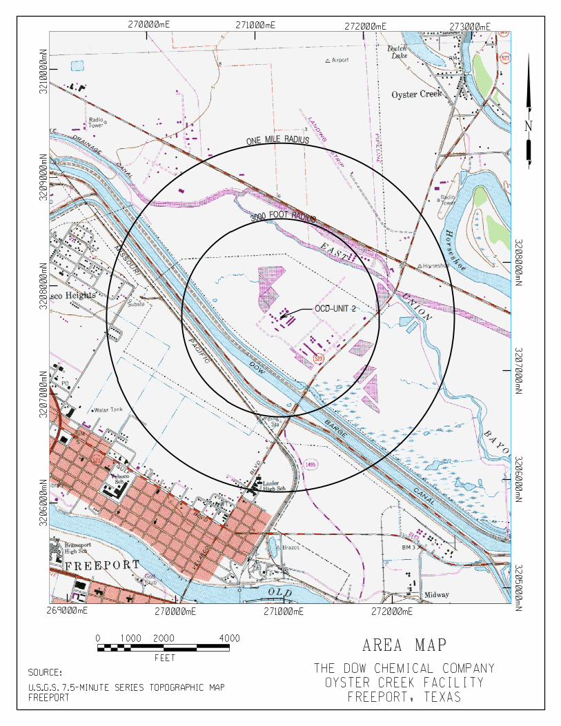
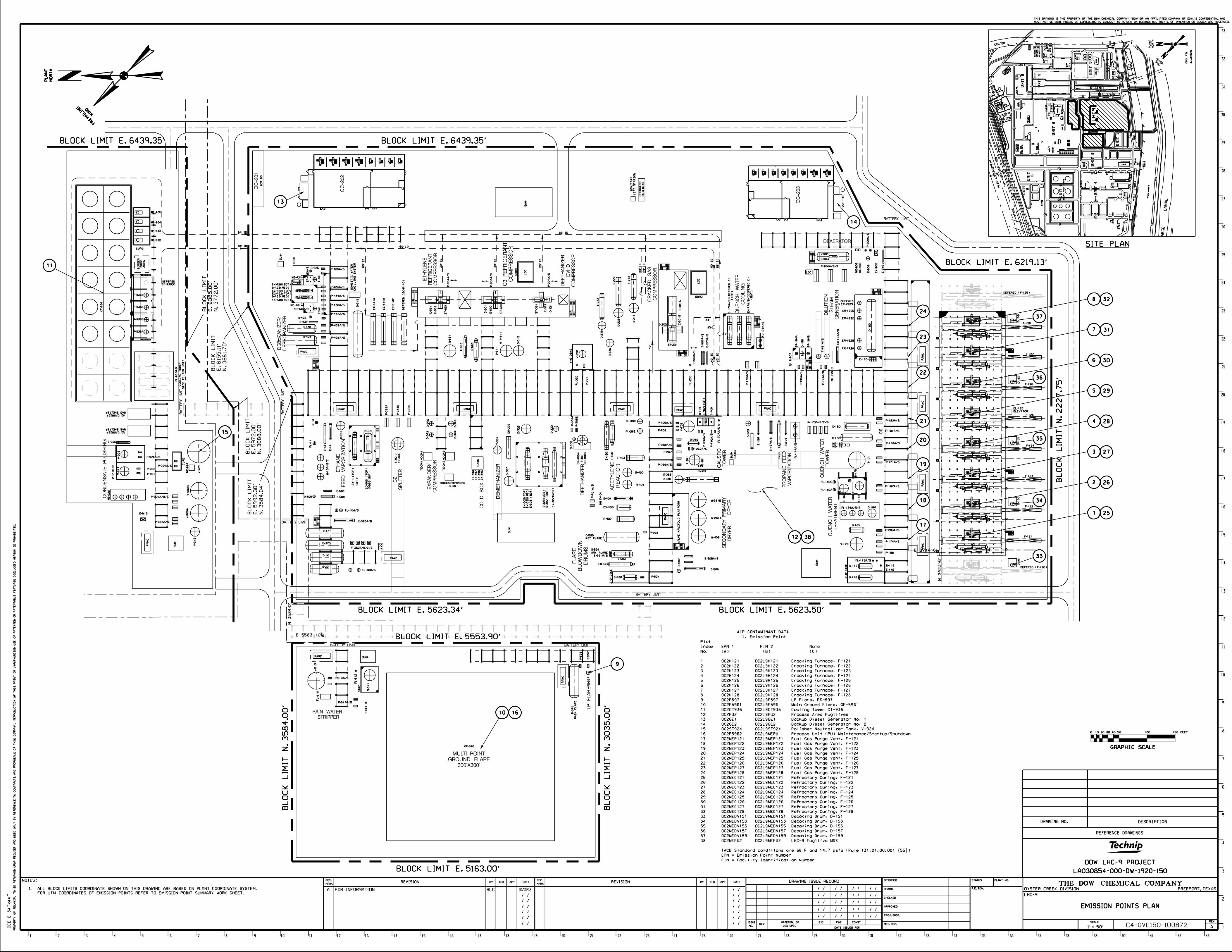
Dow Texas Operations is located in Brazoria County, which is classified as a severe non-attainment area for ozone. An area map for the proposed LHC-9 facility is provided on the subsequent page. The map includes a 3,000-foot radius circle and a 1-mile radius circle. As indicated on the map, there are no schools located within 3,000 feet of the Dow Freeport facility. A plot plan, which identifies the location of the LHC-9 plant and all the associated equipment sources in relation to roads, highways, and other Dow facilities, is provided on the page following the area map.
The Dow Chemical Company Page 5 PSD Greenhouse Gas Permit Ethylene Production Facility (LHC-9) November 28, 2012
1.5 Upstream / Downstream Analysis
Dow does not anticipate any emission increases from upstream or downstream facilities as a result of the addition of the new LHC-9 facility.
1.5.1 Upstream Impacts
The LHC-9 facility will use ethane and propane as feedstocks. A new pipeline is being installed from Mont Belvieu, Texas to the Dow Freeport complex to provide ethane from a 3rd party to the Dow Freeport site. This pipeline is included in the action area for the cross-cutting regulation assessments required for federal permit issuance. Propane is provided to the site by way of an existing propane pipeline and header system.
The cracking furnaces will be equipped with selective catalytic reduction (SCR) technology to minimize emissions of nitrogen oxides (NOX). Ammonia is the reducing agent that will be used in the SCR system to for chemical reduction of the NOX. The project will require installation of ammonia piping from an existing ammonia header that runs throughout the Dow Freeport site to the LHC-9 furnace SCR devices. This installation will trigger fugitive emissions only, and those emission estimates have been included in the TCEQ New Source Review (NSR) permit.
The crude product from the cracking furnaces will be further processed in a series of quench, distillation, compression, and purification steps. No additional energy is needed to process the cracking feed, except for the steam utilized in downstream processes. The steam produced by the cracking furnaces will be sufficient to cover any increased energy needs.
Process off-gas from LHC-9 operations will be used as fuel in LHC-9 furnaces, distributed within the site low pressure fuel gas (LPFG) system, or used for off-site hydrogen recovery. Electricity and steam will be provided to the proposed facility by way of existing cogeneration units. No modifications are necessary to these units as they are currently sized to provide adequate energy to meet current and future site needs.
1.5.2 Downstream Impacts
The primary products produced at the LHC-9 facility (ethylene and propylene) will be used as feed stock for other existing units at the Dow Freeport site or transported via pipeline to existing underground storage caverns. The additional capacity for ethylene and propylene provided by the LHC-9 facility will off-set the quantity of raw materials purchased from 3rd party suppliers.
By-product streams as well as off-gas from the LHC-9 unit may be routed to existing facilities at the site for product recovery and energy recovery. The Dow Freeport site is a highly integrated chemical manufacturing complex. This integration allows product and by-product streams to be processed by downstream plants resulting in efficient and low-cost production capability.
Wastewater generated by the unit will be routed to an existing on-site wastewater treatment facility. The wastewater discharged from the site wastewater treatment plant will not vary from other discharges already managed by this facility; therefore, no new pollutants will be treated or discharged.

The Dow Chemical Company Page 6 PSD Greenhouse Gas Permit Ethylene Production Facility (LHC-9) November 28, 2012
SECTION 2.0 PROCESS DESCRIPTION
The proposed project includes construction of a new ethylene unit (LHC-9) and associated utilities. The new unit will include eight (8) new steam cracking furnaces, recovery equipment, utility, refrigeration, cooling, and treatment systems. The major pieces of recovery equipment include a quench tower, cracked gas compression, caustic wash tower, chilling train, refrigeration systems, deethanizer, ethylene/ethane (C2) splitter, demethanizer, depropanizer, and debutanizer. In addition, a new cooling tower and new flare system will be constructed.
The new plant will process hydrocarbon feedstocks to produce ethylene and other products. A process flow sequence is shown on the block flow diagram, Figure 2-1. Design capacity is included in Appendix A on the Table 2 Material Balance. The operating schedule for this facility is 8760 hours per year.
2.1 Cracking Furnaces
2.1.1 Feed Preparation
Fresh ethane feed to the plant is filtered, dried, mixed with recycle ethane from the C2 splitter, and fed to the furnaces. Crude ethane feed to the plant is mixed with the fresh and recycled ethane feeds and fed to the furnaces.
Fresh propane feed to the plant is filtered and fed to the furnaces. Mixed C3s from the Depropanizer and mixed C4s from the Debutanizer section can be recycled to the feed to the furnaces.
2.1.2 Cracking Furnaces
The cracking section consists of 8 furnaces of proprietary design (EPNs: OC2H121 through OC2H128). These furnaces receive hydrocarbon feeds from the Feed Preparation Section and react them by pyrolysis in the presence of steam to produce a mixed gas stream of products, byproducts, un-reacted feedstocks, and steam. This cracked gas stream is fed to the Quench System. The furnaces also generate high pressure steam, which is fed to the plant steam system.
The furnaces are fired on fuel from the plant fuel gas supply system. Combustion of fuel gas generates the heat required for completing the pyrolysis reaction in the furnace tubes. Emissions such as NOx, CO2, CO, and particulate matter (PM) are generated during combustion, and are vented to atmosphere through the furnace stacks. The furnaces are equipped with burners designed to operate with low NOx, CO, and PM emissions. Selective catalytic reduction (SCR) systems are also included on the furnaces to further control NOx emissions.
2.1.2.1 Furnace Fuels
The furnaces are capable of firing on a variety of fuels. Fuel selection is based on availability and market factors. Typical fuels and their associated terminology for the cracking furnaces are:
Natural Gas Primarily methane; natural gas is supplied to the Dow Freeport site from 3rd party suppliers and arrives by way of existing pipeline systems. This fuel is available for use at the LHC-9 from the existing utility system. The calculations include emissions for firing on Natural Gas as one of the fuel cases.
The Dow Chemical Company Page 7 PSD Greenhouse Gas Permit Ethylene Production Facility (LHC-9) November 28, 2012
Off Gas Primarily a hydrogen/methane stream produced in the LHC-9 process. This stream can be recycled for use in dryer regeneration, used as fuel in the furnaces, or exported to a 3rd party for hydrogen recovery. The calculations include emissions for firing on Off Gas as one of the fuel cases
Resid Gas Residual Gas; a primarily methane/hydrogen stream (less hydrogen though than Off Gas) that is returned from a 3rd party hydrogen recovery facility.
Fuel Gas This term is a general one and refers to whatever fuel is being sent to the furnaces. It could be Off Gas, Natural Gas, or a combination of either of those with Resid Gas. It’s used when the intent is to be non-specific to the composition of the stream being sent to the furnaces for fuel.
Regen Gas Regeneration Gas; this is the Off Gas or Resid Gas streams when being used for the purpose of regenerating LHC-9’s dehydrators.
2.1.2.2 Decoking
During the cracking reaction, coke is formed in the furnace tubes that must be periodically removed by steam/air decoking. In this decoking process the coke is removed by oxidation and spalling. The spalled coke is removed from the decoke effluent in the decoke drum. Particulate matter emissions are controlled by cyclone separators at the decoke drums, which vent to atmosphere (EPNs: OC2MEDV151 through OC2MED159). The furnace operates for approximately fifty (50) days between decokes.
2.2 Product Recovery
2.2.1 Quench System
In the Quench system, the cracked gas product from the furnaces is cooled in a quench tower where the majority of the dilution steam and some of the heavier hydrocarbons are condensed. Cracked gas from other existing facilities at the site may also be fed to the Quench System for the purpose of reducing the need to flare these streams. This is typical during maintenance of the other existing facility. Condensed water and hydrocarbons from the bottom of the tower flow to the Dilution Steam Generation/Quench Water Clean-up Section for further processing. Cooled cracked gas is sent to the Cracked Gas Compression System.
2.2.2 Dilution Steam Generation/Quench Water Clean-up
In the Quench Water Clean-up system, the water and oil from the quench tower is fed to a quench water separator where oil and water separation occurs. The water from the quench water separator is treated further to remove residual oil and is stripped with steam to remove soluble hydrocarbons. This stripped quench water is pumped to the dilution steam generator for the purpose of generating steam for use in the cracking furnaces.
The oil stream from the quench water separator is processed further in the debutanizer to remove contaminants and exits the plant as a pyrolysis gasoline (Pygas) product stream. The Pygas stream is routed to an existing storage tank and combined with a Pygas stream from another existing production unit.
The Dow Chemical Company Page 8 PSD Greenhouse Gas Permit Ethylene Production Facility (LHC-9) November 28, 2012
2.2.3 Cracked Gas Compression
Cracked gas from the quench tower overheads is compressed in three stages in the cracked gas compressor. After the final inter-stage cooling, the compressed cracked gas is forwarded to the Caustic Wash system. The compressor will be driven by steam turbine.
2.2.4 Caustic Wash
The caustic wash tower removes CO2 and sulfur compounds from the cracked gas. The CO2 and sulfur compounds are removed by reaction with caustic (NaOH), forming soluble compounds. Cracked gas leaving the caustic wash tower is cooled, and condensed liquid is separated before the cooled gas is forwarded to the Drying section. Condensed hydrocarbons are continuously removed from the bottom of the tower, along with spent caustic. Spent caustic is processed to remove hydrocarbons and sent forward to the Spent Caustic Treatment.
2.2.5 Dryers
Drying of the cracked gas is necessary to prevent hydrate formation in the colder downstream process operations. Desiccant is used in the dryers to remove moisture. When the desiccant in a dryer becomes saturated with water, it will be regenerated and the standby dryer placed in service. Dried cracked gas is fed to the Deethanizer.
2.2.6 Deethanizer
The Deethanizer separates the cracked gas into an overheads stream of ethane and lighter components, and a bottoms stream of C3 and heavier components. The overheads stream of ethane and lighter components is compressed and fed to the Acetylene Reaction System. The bottoms stream of C3 and heavier components is fed to the Depropanizer for further separation. The Deethanizer overheads compressor will be driven by steam turbine.
2.2.7 Acetylene Reactors
The Acetylene reactors remove acetylene (an undesirable by-product) from the Deethanizer overheads stream through selective hydrogenation to ethylene and ethane. After hydrogenation, the reactor effluent is dried and partially condensed. Liquid and vapor are then separated, with liquid returned to the Deethanizer as reflux and vapor fed to the Demethanizer Section for further separation.
2.2.8 Demethanizer
The Demethanizer Section separates the vapor from the Acetylene Reactor System into a vapor stream of methane and lighter components, and a bottoms stream of ethane and ethylene. First, the stream from the Acetylene Reactor System is partially condensed and vapor/liquid separated in demethanizer feed chillers and knockout drums. The remaining vapor is fed to the Cold box/Expanders Section for further processing. The condensed liquid is fed to the Demethanizer column for further separation.
The Demethanizer column separates the condensed liquid stream into an overheads stream of methane and lighter components, and a bottoms stream of ethane and ethylene. The overheads stream of methane and lighter components is recycled to the Deethanizer. The bottoms stream of ethane and ethylene is fed to the C2 Splitter for further separation.
The Dow Chemical Company Page 9 PSD Greenhouse Gas Permit Ethylene Production Facility (LHC-9) November 28, 2012
2.2.9 Cold box/Expander
The Cold box/Expander Section further processes the vapor stream from the Demethanizer Section to recover ethylene and refrigeration value. The vapor stream from the Demethanizer feed knockout drum is cooled and expanded to recover ethylene. The remaining vapor stream (Off Gas) from the expanders is primarily methane and hydrogen, and is recycled to the Fuel Gas/Dryer Regen System.
2.2.10 C2 Splitter
The C2 splitter separates the Demethanizer bottoms stream into an overheads stream of ethylene, and a bottoms stream of ethane. The overheads stream of ethylene is compressed, condensed, pumped, and leaves the plant as the main product stream. The bottoms stream of ethane is recycled to the Feed Preparation Section. A crude ethylene stream from existing facilities may also be fed to the C2 splitter for separation.
2.2.11 Depropanizer
The Depropanizer separates the Deethanizer bottoms stream into an overheads stream of propane and propylene, and a bottoms stream of C4 and heavier components. The overheads stream of propane and propylene leaves the plant as a mixed C3 product stream, and can be used as makeup to the propylene refrigeration system or recycled to the Feed Preparation Section. The bottoms stream of C4 and heavier components is fed to the Debutanizer for further separation.
2.2.12 Debutanizer
The Debutanizer separates the Depropanizer bottoms stream into an overheads stream of C4 components, and a bottoms stream of C5 and heavier components. The overheads stream of C4s leaves the plant as a mixed C4 product stream, and can be recycled to the Feed Preparation Section. The bottoms stream of C5 and heavier components is combined with oil from the Quench Section and leaves the plant as a Pygas product stream. A crude C4+ stream from existing facilities may also be fed to the Debutanizer for separation.
2.2.13 Fuel Gas/Dryer Regen
The Off Gas from the Cold box/Expander Section is recycled to the Fuel Gas/Dryer Regen system for use in Dryer Regeneration, as fuel in the Cracking Furnaces, or exported as an Off Gas product. The Fuel Gas/Dryer Regen System can be supplemented with Fuel Gas/Regen Gas import, which can include natural gas and other similar hydrogen and methane containing gas streams from other facilities.
Dryers that have been saturated with moisture are regenerated with heated Off Gas, which is recovered in the plant Fuel Gas/Dryer Regen System.
2.3 Refrigeration
2.3.1 C2 Refrigeration
An ethylene refrigeration system will be constructed for providing refrigerant to the proposed plant. The compressor will be driven by steam turbine.
The Dow Chemical Company Page 10 PSD Greenhouse Gas Permit Ethylene Production Facility (LHC-9) November 28, 2012
2.3.2 C3 Refrigeration
A propylene refrigeration system will be constructed for providing refrigerant to the proposed plant. The compressor will be driven by steam turbine.
2.4 Cooling Tower
A cooling tower (EPN: OC2CT936) will be constructed to provide process heat removal. This cooling tower will be a multi-cell, induced draft, counter-flow type cooling tower.
Wet cooling towers provide direct contact between the cooling water and air passing through the tower, and as part of normal operation, a very small amount of the circulating water may be entrained in the air stream and be carried out of the tower as “drift” droplets. Because the drift droplets may contain the same salt impurities as the water circulating through the tower, the particulate matter constituent of the drift droplets is classified as an emission. Cooling water conductivity and total dissolved solids are parameters used estimate particulate emissions from the unit.
VOC emissions from the cooling tower are generated by leakage of hydrocarbons from process heat exchangers into the cooling water system, and are released to atmosphere with the cooling tower fan discharge to atmosphere. The cooling water system will include totalizing flow measurement and on-line analysis to detect and speciate HRVOC (Highly Reactive Volatile Organic Compounds) hydrocarbons in the cooling water.
2.5 Flare System
A new flare system (EPNs: OC2F5961, OC2F5962, and OC2F597) will be constructed to provide safe control of gases vented from the proposed plant. This system will consist of a pressure-assisted flare for managing the main portion of vented gases, and a low pressure flare for managing lower pressure vented gases including those from the plant’s low pressure rated storage tanks. The flare system will be equipped with totalizing flow measurement and on-line analysis to speciate the hydrocarbons in the flared gases, including HRVOCs.
2.6 Rainwater/Wastewater
The proposed plant will include systems to collect rain water and process wastewater.
Rainwater and other pad water such as fire fighting water is collected in sumps located throughout the process area. The contained water is tested for contamination. Clean water is recycled to the cooling water system. Contaminated water is filtered, stripped, and exported to an on-site treatment facility.
A small continuous stream of process wastewater is generated from concentrated blow down of the Dilution Steam Generator, which is necessary for maintenance of water quality. Additional process wastewater is produced during periods of reduced process steam generation, such as during maintenance or cleaning of process steam generation equipment. Process wastewater is collected in a tank and pumped to an on-site waste water treatment facility.
The Dow Chemical Company Page 11 PSD Greenhouse Gas Permit Ethylene Production Facility (LHC-9) November 28, 2012
2.7 Spent Caustic Pretreatment
Spent caustic from the Caustic Wash system is filtered and stripped to remove contaminants prior to being pumped to an existing on-site wet air oxidation (WAO) system. In the wet air oxidation system the spent caustic is further treated to convert sulfides to sulfates, and is then routed to an on-site waste water treatment facility.
2.8 Steam/Condensate/Boiler Feed Water
The proposed project will include a steam system, condensate system, and boiler feed water system. Polished water from the Condensate Collection/Polishing system is de-aerated and pumped to furnaces for high pressure steam generation. High pressure steam generated in the furnaces is used as driver for the plant steam turbines, and is condensed or exported to the Site.
2.9 Condensate Collection/Polishing System
The proposed plant will include a system for collecting steam condensate and polishing to cleanliness specification required for use in high pressure steam generation. Collected steam condensate is polished using ion exchange. The polishing beds become exhausted after removing their maximum capacity of hardness from the water stream, and require regeneration with Hydrochloric Acid (HCl). The Polishing system includes a polisher neutralizer tank (EPN: OCST924) for collection of liquid generated during the regeneration process. This tank vents to atmosphere through a scrubber which controls HCl vapor emissions.
2.10 Storage Tanks
Several new storage tanks are included in the proposed plant. These tanks will store materials such as ammonia, compressor wash oil, lube oil, caustic, spent caustic, sulfuric acid, methanol, and various water and process additives. Some tanks will be routed to control. No increase in GHG emissions are being represented from the proposed storage tanks with atmospheric vents.
2.11 Engines
The plant includes two backup generators sized for selected critical plant electrical loads. Backup power for these critical loads is required to prevent damage to major plant equipment during power interruption. Each generator is powered by a diesel engine (EPNs: OC2GE1 and OC2GE2) and there is one diesel tank associated with each backup generator. These generators are normally not operating, and are only used during power interruptions and during routine readiness testing. Routine testing of the generators is a weekly start and partial load test to ensure readiness for service during interruption of normal power supply.
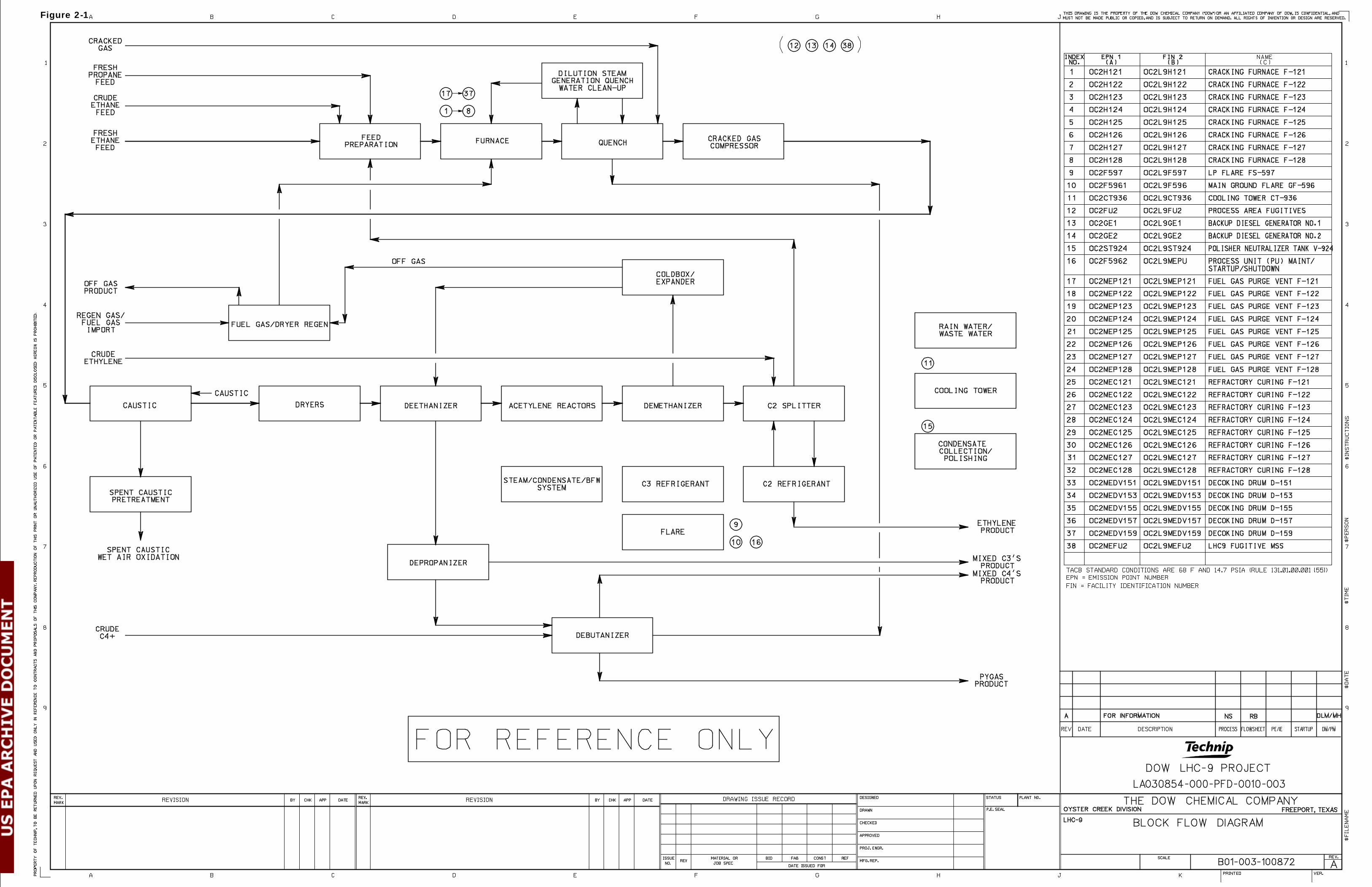
Figure 2-1
The Dow Chemical Company Page 13 PSD Greenhouse Gas Permit Ethylene Production Facility (LHC-9) November 28, 2012
SECTION 3.0 EMISSIONS BASIS
Detailed GHG emission calculations for the proposed LHC-9 facility are provided in Appendix B of this application. The GHG emissions from the proposed LHC-9 facility will include carbon dioxide (CO2), methane (CH4), and nitrous oxide (N2O). GHG emissions are calculated from the following sources for the proposed project:
• Cracking furnaces
• Flare system
• Routine emergency generator testing
• Fugitive emissions from piping components in GHG service
The CO2e emissions are calculated based on the estimated annual mass rates for each applicable GHG multiplied by the global warming potential (GWP) for each specific GHG as provided in Table A-1 of Subpart A of 40 CFR part 98.
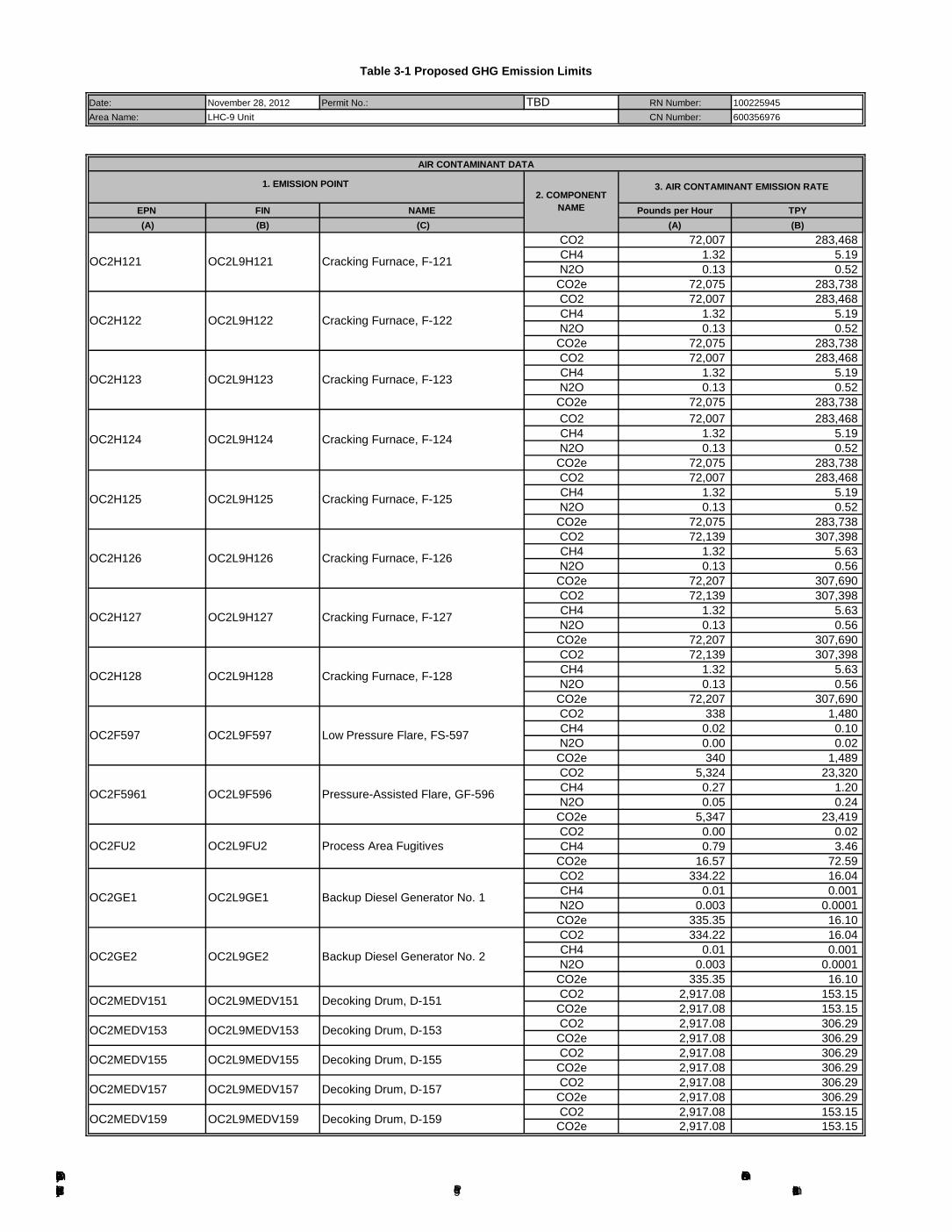
Table 3-1, at the end of this section, provides proposed emission rates for individual GHGs and corresponding CO2e.
3.1 Cracking Furnaces
The LHC-9 facility will include eight steam cracking furnaces. Calculations of GHG emissions from these furnaces and GHG emissions from decoking operations are provided in Appendix B.
3.1.1 Normal Firing
The cracking furnaces will typically combust plant off gas; however, the furnaces may also operate on pipeline quality natural gas. The proposed allowable GHG emissions are based on the maximum emissions from either scenario, which is the combustion of natural gas. The plant must maintain flexibility to fuel the furnaces using either the hydrogen-rich off-gas stream or to use natural gas. Market conditions such for natural gas and hydrogen will influence which fuel is used, therefore substitution of hydrogen for natural gas as an enforceable permit condition is not a viable option. A requirement to use hydrogen fuel in place of natural gas when available and not sold as product is considered to be an acceptable option.
Annual emissions estimates for routine operations assume continuous operation at the expected annual average firing rate. GHG emissions from the furnaces were estimated using EPA’s GHG reporting methodology as detailed in 40 CFR Part 98, Subpart X, §98.243(d) for ethylene production processes.
3.1.2 Decoking Operation
CO2 emissions are produced in the decoking process from the combustion of the carbon buildup on the furnace tubes. To conservatively estimate GHGs from decoking operations, Dow assumed 100% of the coke converts to CO2 during decoking. Emission rates were calculated for each decoking cycle based on the mass of coke that will be combusted. Annual emissions were then calculated by multiplying the per cycle emission rate by the number of decoking cycles per year.
Although the furnaces are fired during decoking operations, firing is at a lower rate than the basis used for annual fuel firing for each furnace. Therefore, fuel firing during decoking operations is already accounted for in the 8,760 hours/year/furnace normal firing scenarios discussed in Section 5.1.1 above.
The Dow Chemical Company Page 14 PSD Greenhouse Gas Permit Ethylene Production Facility (LHC-9) November 28, 2012
Therefore, decoking GHG emissions estimates in Appendix B represent only the incremental GHGs generated during decoking from coke conversion to GHGs.
3.2 Flare System
The flare system consists of a small elevated flare and a pressure-assisted flare. The small elevated flare is designed to control fugitive emissions from process compressor seals. There is also a continuous nitrogen (N2) and natural gas purge to maintain header velocity and heating value of the flared stream. The pressure-assisted flare controls process vents from LHC-9 operations.
Normal flaring operations include controlling vents that can be classified into three main types of activities: fugitive-like sources such as safety relief and pressure control valves that are closed during routine operation, maintenance activities, and process adjustments to maintain product quality. These activities are expected to use the low pressure burners of the pressure-assisted flare. The flow rate is based on measured values of a similar plant with adjustments for capacity and complexity.
Estimated emissions from the flare due to scheduled maintenance, start-up and shutdown (MSS) activities are broken down by activity type. Maintenance flaring includes control of streams generated from clearing equipment in preparation for maintenance. Start-up flaring includes control of streams generated from startup activities in different sections of the facility. Shutdown stream flaring is assumed to be approximately one half of each of the start-up streams.
For each flared stream, the total mass of vapors and the weight percent of each component were used to estimate stream properties and corresponding GHG emissions. The stream characteristics used for the flare GHG emissions basis are provided in Appendix B. Although these stream details are provided for emissions estimation purposes, speciation and total flow rates are based on process design as well as similar operating facilities' typical streams. Speciation and or flow volume may vary depending on process conditions and additional compounds similar to those represented may be present.
GHG emissions estimates are based on natural gas firing for the pilots and process vent firing for the balance of the flared stream. Therefore, the flare GHG emissions are calculated based on 40 CFR Part 98, Subpart X, §98.243(d) emissions estimation methodology.
3.3 Piping Fugitives
The LHC-9 facility will have fugitive emissions from piping components in fuel gas and natural gas service. Fuel gas and natural gas both contain primarily methane, with additional heating value derived mostly from hydrogen (fuel gas) and ethane (natural gas). Other process streams at the LHC-9 facility in volatile organic compound (VOC) service will contain only insignificant quantities of GHGs as compared to other GHG sources at the facility and therefore, are not considered further in this application.
As there are no established GHG piping fugitive emission factors, Dow applied the average Synthetic Organic Chemical Manufacturing Industry (SOCMI) average emissions factors for petrochemical processes to the estimated fuel gas components to estimate fugitive total mass emissions. For the natural gas piping components, Oil and Gas emission factors were used to estimate fugitive total mass emissions. Because many of these components may be in either natural gas or fuel gas service, and because natural gas is over 90% methane (a GHG), Dow conservatively assumed 100% of the mass emissions to be methane.
The Dow Chemical Company Page 15 PSD Greenhouse Gas Permit Ethylene Production Facility (LHC-9) November 28, 2012
3.4 Emergency Generator
Two diesel-fired emergency generators will only operate during emergencies and on regularly scheduled intervals for readiness testing. It is estimated that the generator will be operated a maximum of 100 hours per year for testing. There will be no other emissions from the generator during normal operation.
GHG emissions from the diesel-fired engines follow the approach for general combustion devices represented in 40 CFR Part 98, Subpart C and the emission factors for No. 2 distillate fuel represented in Tables C-1 and C-2 of Part 98.
3.5 Maintenance, Startup, and Shutdown [MSS]
The cracking furnaces will go through a decoke process before shutdown or maintenance activities are performed. The startup of the furnaces is similar to the re-introduction of feed after the decoke process is complete. Therefore, all MSS emissions are a subset of the decoking operation.
The Dow Chemical Company Ethylene Production Facility (LHC-9)
PSD Greenhouse Gas PermitNovember 28, 2012Page 16
Date: November 28, 2012 Permit No.: TBD RN Number: 100225945Area Name: CN Number: 600356976
EPN FIN NAME Pounds per Hour TPY (A) (B) (C) (A) (B)
CO2 72,007 283,468 CH4 1.32 5.19 N2O 0.13 0.52
CO2e 72,075 283,738 CO2 72,007 283,468 CH4 1.32 5.19 N2O 0.13 0.52
CO2e 72,075 283,738 CO2 72,007 283,468 CH4 1.32 5.19 N2O 0.13 0.52
CO2e 72,075 283,738 CO2 72,007 283,468 CH4 1.32 5.19 N2O 0.13 0.52
CO2e 72,075 283,738 CO2 72,007 283,468 CH4 1.32 5.19 N2O 0.13 0.52
CO2e 72,075 283,738 CO2 72,139 307,398 CH4 1.32 5.63 N2O 0.13 0.56
CO2e 72,207 307,690 CO2 72,139 307,398 CH4 1.32 5.63 N2O 0.13 0.56
CO2e 72,207 307,690 CO2 72,139 307,398 CH4 1.32 5.63 N2O 0.13 0.56
CO2e 72,207 307,690 CO2 338 1,480 CH4 0.02 0.10 N2O 0.00 0.02
CO2e 340 1,489 CO2 5,324 23,320 CH4 0.27 1.20 N2O 0.05 0.24
CO2e 5,347 23,419 CO2 0.00 0.02 CH4 0.79 3.46
CO2e 16.57 72.59 CO2 334.22 16.04 CH4 0.01 0.001 N2O 0.003 0.0001
CO2e 335.35 16.10 CO2 334.22 16.04 CH4 0.01 0.001 N2O 0.003 0.0001
CO2e 335.35 16.10 CO2 2,917.08 153.15
CO2e 2,917.08 153.15 CO2 2,917.08 306.29
CO2e 2,917.08 306.29 CO2 2,917.08 306.29
CO2e 2,917.08 306.29 CO2 2,917.08 306.29
CO2e 2,917.08 306.29 CO2 2,917.08 153.15
CO2e 2,917.08 153.15
OC2F597 OC2L9F597 Low Pressure Flare, FS-597
OC2H128 OC2L9H128 Cracking Furnace, F-128
OC2F5961 OC2L9F596 Pressure-Assisted Flare, GF-596
OC2GE1 OC2L9GE1 Backup Diesel Generator No. 1
Process Area FugitivesOC2FU2 OC2L9FU2
OC2H122 OC2L9H122 Cracking Furnace, F-122
OC2H123
OC2H125 OC2L9H125 Cracking Furnace, F-125
OC2H124 OC2L9H124 Cracking Furnace, F-124
OC2H126 OC2L9H126 Cracking Furnace, F-126
OC2H127
OC2L9H123
OC2L9H127
Table 3-1 Proposed GHG Emission Limits
LHC-9 Unit
1. EMISSION POINT 2. COMPONENT
NAME
3. AIR CONTAMINANT EMISSION RATE
AIR CONTAMINANT DATA
Cracking Furnace, F-127
OC2H121 OC2L9H121 Cracking Furnace, F-121
Cracking Furnace, F-123
OC2GE2 OC2L9GE2 Backup Diesel Generator No. 2
OC2MEDV151 OC2L9MEDV151 Decoking Drum, D-151
OC2MEDV153 OC2L9MEDV153 Decoking Drum, D-153
OC2MEDV155 OC2L9MEDV155 Decoking Drum, D-155
OC2MEDV157 OC2L9MEDV157 Decoking Drum, D-157
OC2MEDV159 OC2L9MEDV159 Decoking Drum, D-159
The Dow Chemical Company Page 17 PSD Greenhouse Gas Permit Ethylene Production Facility (LHC-9) November 28, 2012
SECTION 4.0 BEST AVAILABLE CONTROL TECHNOLOGY
In the EPA guidance document titled PSD AND TITLE V PERMITTING GUIDANCE FOR GREENHOUSE GASES – MARCH 2011, EPA recommended the use of the Agency's five-step "top-down" BACT process to determine BACT for GHGs1
EPA has broken down this analytical process into the following five steps:
. In brief, the top-down process calls for all available control technologies for a given pollutant to be identified and ranked in descending order of control effectiveness. The permit applicant should first examine the highest-ranked ("top") option. The top-ranked options should be established as BACT unless the permit applicant demonstrates to the satisfaction of the permitting authority that technical considerations, energy, environmental, or economic impacts justify a conclusion that the top ranked technology is not "achievable" in that case. If the most effective control strategy is eliminated in this fashion, then the next most effective alternative should be evaluated, and so on, until an option is selected as BACT.
Step 1: Identify all available control technologies
Step 2: Eliminate technically infeasible options
Step 3: Rank remaining control technologies
Step 4: Evaluate most effective controls and document results
Step 5: Select the BACT
The project contains the following sources of GHG emissions:
• Cracking Furnaces
• Decoking Activities
• Flare System
• Emergency Generators
• Piping Fugitives
CO2 emissions account for approximately 99 percent of the total CO2e emissions for the proposed project. CH4 and N2O contribute insignificantly to the overall GHG emissions potential. Therefore, the GHG BACT analysis is focused on CO2.
Dow searched the EPA RACT/BACT/LAER Clearinghouse (RBLC) database only for applicable CO2 BACT determinations to assist in identifying potential GHG control technologies relevant to the proposed emissions sources. The results of a RBLC Database search are included in Appendix D to this application.
The EPA recognizes that currently there are essentially only two methods for potentially reducing and controlling GHG emissions. These controls are improved energy efficiency and carbon capture and sequestration, and are included in this BACT analysis.
1 Office of Air Quality Planning and Standards, PSD and Title V Permitting Guidance for Greenhouse Gases, United States Environmental Protection Agency, pg 18, March 2011.
The Dow Chemical Company Page 18 PSD Greenhouse Gas Permit Ethylene Production Facility (LHC-9) November 28, 2012
4.1 BACT for Cracking Furnaces and Recovery Section
The overall energy efficiency of an ethylene plant is primarily determined by two factors: 1) the thermal efficiency of the cracking furnaces and 2) the efficiency of the recovery section of the plant in separating the cracked gas into final products. Each section of the plant consumes about 50% of the total energy associated with ethylene production. While the furnaces are the primary CO2 emission source in the plant, the total energy consumption of an ethylene plant is distributed evenly across the furnaces and the recovery section. To analyze the efficiency of a new ethylene plant, it is necessary to evaluate both the Furnace and Recovery section efficiency and because of the steam and energy integration, the plant as a whole.
The majority of GHG emissions associated with the LHC-9 production unit are from the cracking furnaces. Stationary combustion sources primarily emit CO2, but they also emit a small amount of N2O and CH4. The new furnaces being installed for this project will be equipped with the latest technology for optimum thermal efficiency. The proposed cracking furnaces will be fueled by natural gas and plant off gas. The combined fuel gas composition will contain methane, 1-2% other materials (including ethylene), and hydrogen (typically 30-80% by volume). The furnaces will be equipped with a selective catalytic reduction system (SCR) to reduce NOX emissions.
4.1.1 Step 1: Identify Available Control Technologies
The best way to minimize combustion related GHG emissions is through thermal efficiency achieved through design and operations. Good combustion practices are considered BACT. These practices are based on EPA guidance are summarized in Table 4-2.
The following technologies were identified as potential control options for the furnaces based on review of available information and data sources:
1. Carbon Capture and Storage (CCS) as an add-on control 2. Use of Low-Carbon Gaseous Fuels 3. Energy and Thermal Efficient Design
• Efficient Furnace and Recovery Section Design • Oxygen Trim Control and Good Combustion Practices • Periodic Tune Ups and Maintenance
4.1.2 Step 2: Eliminate Technically Infeasible Options
The technologies identified in Step 1 are all technically feasible.
4.1.3 Step 3: Rank Remaining Control Technologies
Because thermal efficiencies are work practice standards, it is difficult to identify discriminate control efficiencies for ranking. For this reason, the technologies listed in Step 1 have not been ranked, and are addressed in detail in Step 4.
The Dow Chemical Company Page 19 PSD Greenhouse Gas Permit Ethylene Production Facility (LHC-9) November 28, 2012
4.1.4 Step 4: Evaluate the Most Effective Controls
4.1.4.1 Carbon Capture and Storage
CO2 capture is a relatively new concept. In its March 2011 PSD permitting guidance for GHGs, EPA takes the position that, “for the purpose of a BACT analysis for GHGs, EPA classifies CCS as an add-on pollution control technology that is “available” for facilities emitting CO2 in large amounts, including fossil fuel-fired power plants, and for industrial facilities with high-purity CO2 streams (e.g., hydrogen production, ammonia production, natural gas processing, ethanol production, ethylene oxide production, cement production, and iron and steel manufacturing). For these types of facilities, CCS should be listed in Step 1 of a top-down BACT analysis for GHGs”. (Footnote 1 pg 17)
These emerging carbon capture and storage (CCS) technologies generally consist of processes that separate CO2 from combustion process flue gas, compression of the separated CO2, transportation via pipeline to a site for injection and then inject it into geologic formations such as oil and gas reservoirs, un-mineable coal seams, and underground saline formations.
Of the emerging CO2 capture technologies that have been identified, only amine absorption is currently commercially used for state-of-the-art CO2 separation processes. Amine absorption has been applied to processes in the petroleum refining and natural gas processing industries and for exhausts from furnaces. Other potential absorption and membrane technologies are currently considered developmental.
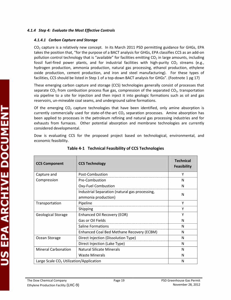
Dow is evaluating CCS for the proposed project based on technological, environmental, and economic feasibility.
Table 4-1 Technical Feasibility of CCS Technologies
CCS Component CCS Technology Technical Feasibility
Capture and Compression
Post-Combustion Y Pre-Combustion N Oxy-Fuel Combustion N Industrial Separation (natural gas processing, ammonia production)
N
Transportation Pipeline Y Shipping Y
Geological Storage Enhanced Oil Recovery (EOR) Y Gas or Oil Fields N Saline Formations N Enhanced Coal Bed Methane Recovery (ECBM) N
Ocean Storage Direct Injection (Dissolution Type) N Direct Injection (Lake Type) N
Mineral Carbonation Natural Silicate Minerals N Waste Minerals N
Large Scale CO2 Utilization/Application N
The Dow Chemical Company Page 20 PSD Greenhouse Gas Permit Ethylene Production Facility (LHC-9) November 28, 2012
CO2 Capture and Compression - According to the U.S. Department of Energy's National Energy Technology Laboratory (DOE-NETL) separating CO2 from flue gas streams is challenging for several reasons:
- CO2 is present at dilute concentrations (13-15 volume percent in coal-fired systems and 3-4 volume percent in gas-fired turbines) and at low pressure (15-25 pounds per square inch absolute [psia]), which dictates that a high volume of gas be treated;
- Trace impurities (particulate matter, sulfur dioxide, nitrogen oxides) in the flue gas can degrade sorbents and reduce the effectiveness of certain CO2 capture processes; and
- Compressing captured or separated CO2 from atmospheric pressure to pipeline pressure (about 2,000 psia) represents a large auxiliary power load on the overall power plant system.2
Further, the Obama Administration's Interagency Task Force on Carbon Capture and Storage confirms this in its August 2010 report on the current status of development of CCS systems:
"Current technologies could be used to capture CO2 from new and existing fossil energy power plants; however, they are not ready for widespread implementation primarily because they have not been demonstrated at the scale necessary to establish confidence for power plant application. Since the CO2 capture capacities used in current industrial processes are generally much smaller than the capacity required for the purposes of GHG emissions mitigation at a typical power plant, there is considerable uncertainty associated with capacities at volumes necessary for commercial deployment.”3
Separating CO2 from the cracking furnaces exhaust streams at the proposed LHC-9 facility is challenging because CO2 is present in dilute concentrations in the furnace exhaust streams. The exhausts contain 9 vol% (natural gas firing) and 5 vol% (off gas firing) or less CO2 in the stack gas on an average annual basis. These are not high-purity streams, as recommended in USEPA's guidance. PM would have to be removed from the CO2 stream without causing excessive back pressure on the upstream systems. Additionally, the temperature would have to be reduced prior to separation, compression, and transmission.
To achieve the necessary CO2 concentration and temperature for effective sequestration, the recovery and purification of CO2 from the stack gases would require additional equipment, operating complexity, and increased energy consumption resulting in energy and environmental/air quality penalties. This may, in turn, potentially increase the natural gas fuel use of the plant, with resulting increases in emissions of non-GHG pollutants, to overcome these efficiency losses, or would result in less energy being produced. The Report of the Interagency Task Force on Carbon Capture and Storage has estimated that an energy penalty of as much as 15% would result from inclusion of CO2 capture (Footnote 4, pg 21) and would also result in an overall loss of energy efficiency.
CO2 Transport - Even if it is assumed that the CO2 could be segregated efficiently from the furnaces exhaust, it would need to be compressed to the pressure of the proposed CO2 pipeline
2 DOE-NETL, Carbon Sequestration: FAQ Information Portal,
http://www.netl.doe.gov/technologies/carbon_seq/faqs.html 3 President Obama's Interagency Task Force on Carbon Capture and Storage, Report of the Interagency Task Force on Carbon Capture and Storage, August 2010, p. 50.
The Dow Chemical Company Page 21 PSD Greenhouse Gas Permit Ethylene Production Facility (LHC-9) November 28, 2012
and the high volume stream would need to be transported via pipeline to a geologic formation capable of long-term storage.
The capabilities for CO2 storage in the vicinity around Freeport are early in development, and there is tenuous commercial viability and demonstration of large-scale, long-term CO2 storage; therefore, the capital and legal risks of building infrastructure solely for CO2 storage from this LHC-9 project are unreasonable. However, if a pipeline was constructed, Denbury Resources owns and operates a CO2 pipeline that has a terminus point at Hastings Field4
Other potential sequestration sites in Texas, which are presently commercially viable, such as the SACROC enhanced oil recovery unit in the Permian Basin, are more than 500 miles from the proposed project site. The closest site that is currently being field-tested to demonstrate its capacity for large-scale geological storage of CO2 is the Southeast Regional Carbon Sequestration Partnership's (SECARB) Cranfield test site located in Adams and Franklin Counties, Mississippi and is over 400 miles away from the proposed project site. Therefore, assuming that it is eventually demonstrated to indefinitely store a substantial portion of the large volume of CO2 generated by the proposed project, a very long and sizable pipeline would need to be constructed to transport the large volume of high-pressure CO2 from the plant to the potential storage facility. Typical costs for installation of a pipeline for flat, dry areas can be estimated at $50,000 (Footnote 4) per inch-diameter per mile. Thus, the high cost of CO2 transport via pipelines 50 miles or greater in length renders it infeasible for the proposed project.
, and is in reasonable proximity for a tie-in to Dow Freeport. The Denbury Green Pipeline that crosses the Galveston Bay area is located approximately 60 miles from Dow Freeport and the Hastings Field EOR site is approximately 47 miles from Dow Freeport; however, there is no existing connection to the pipeline for Hastings Field and currently the level of anthropogenic sources of CO2 in the Green Pipeline being sent to Hastings Field is minimal.
CO2 Storage - Even if it is assumed that CO2 capture and compression could feasibly be achieved for the proposed project and that the CO2 could be transported economically, it must be stored in a suitable sequestration site. A suitable reservoir or geologic formation is not located within a reasonable proximity to the proposed site.
Potential storage sites, including enhanced oil recovery (EOR) sites and saline formations exist in Texas, Louisiana, and Mississippi. The Southeast Texas enhanced oil recovery (EOR) reservoir and other geologic formation sites are all early in development and there is tenuous commercial viability and demonstration of large-scale, long-term CO2 storage; therefore the capital cost and legal risks of building infrastructure solely for CO2 storage from this LHC-9 project are economically challenging. There are salt dome caverns near the site; however, these limestone formations have not been demonstrated to safely store acid gases such as CO2, nor is there adequate availability of space. Instead, these domes are used for cyclical storage of liquefied petroleum gases (LPGs) for use in the Gulf Coast as well as for shipment throughout the United States via pipeline. To replace this critical active storage with long-term CO2 sequestration would necessarily jeopardize energy supplies locally and nationally. Other potential sequestration sites in Texas that are presently commercially viable, such as the SACROC enhanced oil recovery unit in the Permian Basin, are more than 500 miles from the proposed project site. The closest site that is currently being field-tested to demonstrate its capacity for large-scale geological storage of CO2 is the Southeast Regional Carbon Sequestration Partnership's (SECARB) Cranfield test site located in Adams and Franklin Counties. Mississippi
4 Denbury, Green Pipeline Projects, available at http://www.denbury.com/Corporate-Responsibility/Pipeline-Projects/green-pipeline-project/default.aspx (last visited October 10, 2012).

The Dow Chemical Company Page 22 PSD Greenhouse Gas Permit Ethylene Production Facility (LHC-9) November 28, 2012
and is over 400 miles away from the proposed project site, thereby making CCS infeasible for the project.
In addition, potential environmental impacts that would still require assessment before CCS technology can be considered feasible include:
- Uncertainty concerning the significance of dissolution of CO2 into brine;
- Risks of brine displacement resulting from large-scale CO2 injection, including a pressure leakage risk for brine into underground drinking water sources and/or surface water;
- Risks to fresh water as a result of leakage of CO2, including the possibility for damage to the biosphere, underground drinking water sources, and/or surface water, and potential effects on wildlife.
Economic Analysis - Based on the reasons provided above, Dow believes that CCS is not a technically feasible control option for the proposed cracking furnaces at Dow’s LHC-9 facility. However, an economic feasibility analysis is in progress for a carbon capture and transport system to address questions from the public and EPA concerning cost. Dow is working to tailor the estimate to the site parameters and the LHC-9 project. This cost estimate will be submitted at a later date once final estimates are received.
4.1.4.2 Low Carbon Gaseous Fuel
CO2 is a product of combustion generated from any carbon-containing fuel. The preferential use of gaseous fuels such as LHC-9 off gas, resid gas, or natural gas is a method of lowering CO2 emissions versus the use of solid or liquid fuels .
The off gas from LHC-9 can either be fueled in the LHC-9 furnaces or exported for hydrogen recovery. When operating on off gas, the furnace fuel will have a CO2 footprint of approximately 51 lb/MM btu HHV as compared or Resid Gas at approximtately 100 lb/MM btu HHV or Natural Gas at 118 lb/MM btu HHV. These all compare favorably to the use of solid or liquid fuels.
While the export of LHC-9’s hydrogen-rich offgas for hydrogen recovery would increase LHC-9’s CO2 emissions, hydrogen recovery from ethylene processes is viable for the industry as a whole. Purity hydrogen is vital to the oil refining business. Hydrogen is necessary for lightening (hydrocracking) and desulfurizing (hydrotreating) of heavy crude oils. While the export of LHC-9 off gas for Hydrogen Recovery would increase the CO2 production of LHC-9, the industry as a whole benefits as the CO2 increase of hydrogen recovery is calculated to be less than 80% of the equivalent CO2 footprint of Steam-Methane Reforming, the most common alternative method in the industry for Hydrogen Production.
LHC-9 will be designed to operate the furnaces on its own off gas. However, because of its importance to the refining industry and the cost of alternative methods of production, the value of chemical hydrogen is higher than its equivalent fuel value. Economic conditions will determine whether the LHC-9 off gas is used for Hydrogen Recovery or for fuel on the LHC-9 furnaces. When this Off Gas is unavailable or being exported, the alternate fuel will be resid gas and/or natural gas. Resid Gas and Natural gas have a fairly low CO2 emission factors, making them a more attractive secondary fuel with regard to reducing GHG emissions than other liquid or solid feuls. Market conditions for natural gas and hydrogen will influence which fuel is used, therefore substitution of hydrogen for natural gas as an enforceable permit condition is not a viable option. Using off gas fuel in place of natural gas when available and not sold as product is considered to be an acceptable option.

The Dow Chemical Company Page 23 PSD Greenhouse Gas Permit Ethylene Production Facility (LHC-9) November 28, 2012
4.1.4.3 Energy and Thermal Efficiency
Overall CO2 emissions directly related to the LHC-9 plant operations are inversely proportional to the overall plant efficiency. As plant efficiency improves, less energy is consumed and subsequently less CO2 is emitted for the same amount of production.
The overall energy efficiency of an ethylene plant is primarily determined by two factors: 1) the thermal efficiency of the cracking furnaces and 2) the efficiency of the recovery section of the plant in separating the cracked gas into final products. Each section of the plant consumes about 50% of the total energy associated with ethylene production. While the furnaces are the primary CO2 emission source in the plant, the energy consumption of an ethylene plant is in fact distributed evenly across the furnaces and the recovery section. To analyze the efficiency of a new ethylene plant, it is necessary to evaluate both the furnace and recovery section efficiency and because of the steam and energy integration, the plant as a whole.
Dow will implement an energy efficient technology for both the furnaces and the recovery section that will result in fewer overall emissions for all air pollutants per unit of production. The paragraphs below summarize the most significant factors that influence the efficiency of the plant and the benchmarking data will demonstrate that the chosen design will be an industry leader in energy efficiency.
Efficient Recovery Section Design and Operation - The main factor determining the energy efficiency of the recovery section of an ethylene plant is the effectiveness of the selected flowsheet design to efficiently separate the crack gas from the furnaces into the final products. Factors influencing the flowsheet efficiency include:
• Heat and refrigeration recovery and integration • Sequence of product separation and distillation • Efficiency of selected unit operations such as steam turbines and distillation columns • Minimizing recycles and losses.
Dow’s evaluation and selection of the available ethylene technologies took into careful consideration all attributes of the technology including ethylene yield, reliability, and energy efficiency. Since the overall efficiency of an ethylene unit is highly dependent on both the furnaces and the recovery section efficiency and considering the complexity of analyzing different technical options for use of fuel, steam, and electricity as energy inputs, the best measurement for analyzing the efficiency of the entire plant is overall plant energy consumption per unit of production. As the benchmarking data demonstrates, Dow’s selected technology will be an industry leader in efficiency.
Operation and Maintenance – The efficiency of the LHC-9 recovery section will need to be monitored and maintained in order to retain the full benefit of the selected design. This will include the following steps:
• Continuous process monitoring, automated process control, and advanced control techniques
• Routine process cleaning and maintenance as required • Maintaining design operating rates.
The Dow Chemical Company Page 24 PSD Greenhouse Gas Permit Ethylene Production Facility (LHC-9) November 28, 2012
Where fouling potential exists, the Dow design will incorporate either spare equipment or on-line cleaning methods where practical to maintain efficient operation between major maintenance intervals.
Efficient Furnace Design and Operation - As described in the previous section, the cracking furnaces are the single largest fuel consumer and account for more the 50% of the total energy consumption of the LHC-9 plant. The more energy efficient the furnace design, the less fuel is needed, which results in lower emissions of air pollutants. Dow’s technology selection took into account the efficiency of the cracking furnaces as a key contributor to the overall efficiency of the ethylene plant.
The operational efficiency of the cracking furnaces is dependent on an efficient design and effective operation and maintenance practices. The sections that follow describe the factors that contribute to these key attributes.
Heat Recovery - The efficiency of the cracking furnaces is determined by heat loss to flue gas, process effluent, and firebox walls. To maximize the overall furnace efficiency, all three losses are minimized. The main factor determining the energy efficiency of the cracking furnaces is the effectiveness of the selected design to capture the fired duty for process and steam production use and minimize the losses stated above.
The hot process effluent from the furnace cracking coils is cooled in a series of transfer line exchangers which produce high pressure steam and/or preheat boiler feed water. The process is cooled to the maximum extent possible while avoiding the condensing of heavy process components.
The convection section of the furnace is designed to preheat hydrocarbon feed, dilution steam, and boiler feed water and to superheat the high pressure steam to reduce to the flue gas temperature to the extent that the final exiting flue gas temperature is reduced to its practical limit. The lower practical limit for flue gas is set by margin above acid gas dewpoint and/or practical temperature approach to the streams being preheated.
The wall heat losses are minimized through specification of specialized insulation materials. Proper insulation not only minimizes the heat loss, but also minimizes the furnace firebox outside wall temperatures, an important safety factor for the heater design.
The LHC-9 furnaces will be designed for a thermal efficiency of 93% or higher on a LHV basis (considering stack and wall losses) when cracking feedstock. During start-up and decoking operation the thermal efficiency is limited to a practical limit of 74%, but the firing duty is reduced to approximately 1/3 of normal duty during this time. The 93% thermal efficiency will result in a stack temperature of 290°F or less. The benchmarking data presented will show that the selected design will be an industry leader in furnace thermal efficiency.
Oxygen Trim Control and Good Combustion Practices - The effect of excess air on furnace efficiency is due to the large percentage of nitrogen in the air. This nitrogen absorbs heat from the combusted fuel. Heat not transferred to produce product exhausts to the atmosphere. When excess air increases, larger volumes of nitrogen absorb more heat from the fuel and exhaust the incremental heat to atmosphere. Therefore, furnace efficiency drops as excess air increases. Some excess air must be present to completely combust the fuel. When there is insufficient air present to burn the fuel, partially oxidized fuel will be present. Partially oxidized fuel would be in the form of carbon monoxide and organic carbons that did not fully oxidize to carbon dioxide.
The Dow Chemical Company Page 25 PSD Greenhouse Gas Permit Ethylene Production Facility (LHC-9) November 28, 2012
The Dow design will include fuel gas composition and heating value analysis and flue gas oxygen analysis to optimize the fuel to air ratio continuously. This will enable Dow to monitor the amount of excess air added to the furnaces and optimize the excess air to provide good combustion and maximum furnace thermal efficiency
Periodic Tune-Ups and Maintenance- While it is difficult to directly quantify the efficiency benefits of furnace tune-ups and maintenance, the furnaces must be well maintained in order to achieve the design efficiencies stated in the previous section. The furnace operation will be closely monitored and the furnace equipment routinely inspected to maintain efficient operation.
Monitoring and inspection will include:
• Monitoring flue gas temperature, excess oxygen, and carbon monoxide. • Monitoring temperatures of the flue gas and cracked gas effluent at each heat recovery
step. • Monitoring and trending firing rate relative to feedstock and production. • Visually inspecting furnace firebox seals at locations where tramp air can enter the box. • Thermal scans of the firebox walls for heat leakage.
Routine maintenance and tune-up activities to make corrections on an “as needed” basis will include (but not limited to):
• Process cleaning of transfer line exchangers • Cleaning, maintenance, and/or replacement of burner tips • Decoking of furnace coils. • Maintenance and calibration of oxygen analyzers, temperature measurements, and
flow measurements. • Replacement of the furnace radiant section tubes
The Dow design for LHC-9 provides a complete spare furnace such that the plant can be operated efficiently at its design capacity while performing these routine maintenance activities on each furnace. This allows Dow to better manage maintenance activities and decoking operations, thus minimizing the reduction of furnace efficiency.
The Dow Chemical Company Page 26 PSD Greenhouse Gas Permit Ethylene Production Facility (LHC-9) November 28, 2012
4.1.4.4 Benchmarking Efficiency
In order to select the best available technology for energy efficiency of the Cracking Furnaces and the Recovery Section of LHC-9, Dow carefully evaluated all the available ethylene technologies. In addition to benchmarking each of the available technologies against each other, Dow also benchmarked against Dow’s existing ethylene plants and against industry benchmark data.
For industry data, Dow benchmarks using data from Solomon Associates. The Global Olefins Benchmarking Study, conducted by Solomon Associates, is the most comprehensive standard globally by which ethylene plants are benchmarked on all facets of performance, including thermal efficiency. Appendix E contains a letter of statement from Solomon Associates that summarizes the energy performance of the LHC-9 proposed design with other ethylene production plants.
Dow currently has several ethylene plants operating in North America and additional plants internationally. Some of these existing units operate primarily on the same ethane and propane feedstock as LHC-9. This experience not only gives Dow the experience to understand, evaluate, and select the best available technology, it also provides good data for internal benchmarking.
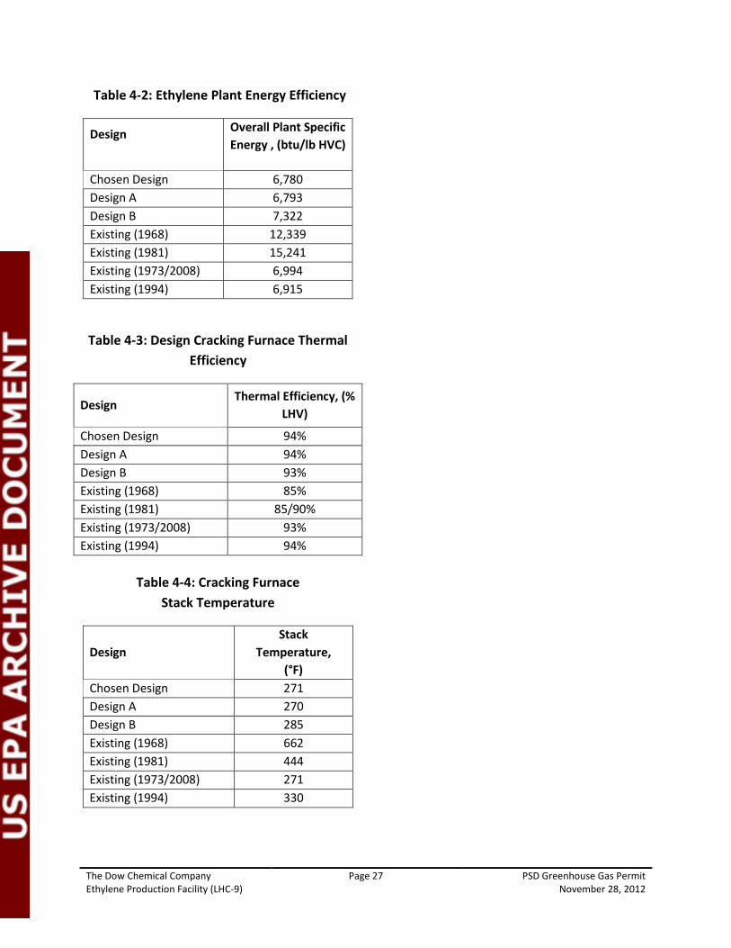
Table 4-2 provides the total energy consumption of the ethylene plant expressed as btu/lb of high-value chemicals (HVC = ethylene, propylene, butadiene, and hydrogen) taking into account all fuel, steam, and electricity consumed in the plant.. The technical alternatives studied and Dow’s newer plants are very similar in overall energy performance. The older designs have much higher overall energy consumption (lower efficiency). The design selected will have an industry leading energy efficiency.
Table 4-3 compares the thermal efficiency on a LHV basis of the cracking furnaces for the technical alternatives studied and Dow’s existing plants. As one of the major energy consumers in the ethylene plant, overall plant performance is dependent on an efficient furnace design. The design selected will achieve the highest practical energy efficiency.
Table 4-4 provides a comparison of furnace flue gas stack temperatures for the technical alternatives studied and Dow’s existing plants. As the primary source of unrecovered energy in the cracking furnace, the flue gas temperature is the key indicator of furnace efficiency. The design selected by Dow will have the lowest practical stack temperature resulting in high energy efficiency.
With all the above factors considered, Dow has calculated that the ethylene plant will achieve a 24 hour rolling average GHG emissions per lb or ethylene of 1.2 lb/lb and an annual GHG emission rate of 1.1 lb/lb. See the calculations provided below. For the chosen design, the overall GHG emissions per pound of ethylene produced compare closely to EPA’s draft permits for other ethylene plants.
597,598 lb/hr CO2e ÷ 490,000 lb/hr ethylene maximum = 1.2 lb CO2e / lb ethylene 2,367,999 tpy CO2e ÷ 2,102,100 tpy ethylene maximum = 1.1 lb CO2e / lb ethylene
As the benchmarking data demonstrates and as the support letter from Solomon Associates confirms, the technical alternatives selected by Dow will be a leader in energy efficiency for ethane cracking plants.
The Dow Chemical Company Page 27 PSD Greenhouse Gas Permit Ethylene Production Facility (LHC-9) November 28, 2012
Table 4-2: Ethylene Plant Energy Efficiency
Design Overall Plant Specific Energy , (btu/lb HVC)
Chosen Design 6,780 Design A 6,793 Design B 7,322 Existing (1968) 12,339 Existing (1981) 15,241 Existing (1973/2008) 6,994 Existing (1994) 6,915
Table 4-3: Design Cracking Furnace Thermal Efficiency
Design Thermal Efficiency, (%
LHV)
Chosen Design 94% Design A 94% Design B 93% Existing (1968) 85% Existing (1981) 85/90% Existing (1973/2008) 93% Existing (1994) 94%
Table 4-4: Cracking Furnace Stack Temperature
Design Stack
Temperature, (°F)
Chosen Design 271 Design A 270 Design B 285 Existing (1968) 662 Existing (1981) 444 Existing (1973/2008) 271 Existing (1994) 330
The Dow Chemical Company Page 28 PSD Greenhouse Gas Permit Ethylene Production Facility (LHC-9) November 28, 2012
4.1.5 Step 5: Select BACT
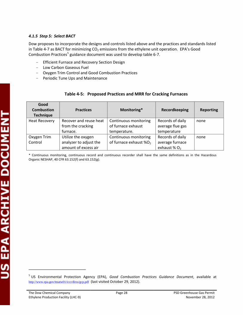
Dow proposes to incorporate the designs and controls listed above and the practices and standards listed in Table 4-7 as BACT for minimizing CO2 emissions from the ethylene unit operation. EPA’s Good Combustion Practices5
- Efficient Furnace and Recovery Section Design
guidance document was used to develop table 6-7.
- Low Carbon Gaseous Fuel - Oxygen Trim Control and Good Combustion Practices - Periodic Tune Ups and Maintenance
Table 4-5: Proposed Practices and MRR for Cracking Furnaces
Good Combustion Technique
Practices Monitoring* Recordkeeping Reporting
Heat Recovery Recover and reuse heat from the cracking furnace.
Continuous monitoring of furnace exhaust temperature.
Records of daily average flue gas temperature
none
Oxygen Trim Control
Utilize the oxygen analyzer to adjust the amount of excess air
Continuous monitoring of furnace exhaust %O2
Records of daily average furnace exhaust % O2
none
* Continuous monitoring, continuous record and continuous recorder shall have the same definitions as in the Hazardous Organic NESHAP, 40 CFR 63.152(f) and 63.152(g).
5 US Environmental Protection Agency (EPA), Good Combustion Practices Guidance Document, available at http://www.epa.gov/ttnatw01/iccr/dirss/gcp.pdf (last visited October 29, 2012).
The Dow Chemical Company Page 29 PSD Greenhouse Gas Permit Ethylene Production Facility (LHC-9) November 28, 2012
4.2 BACT for Decoking Activities
The cracking furnaces require periodic decoking to remove coke deposits from the furnace tubes. Coke buildup is unavoidable in cracking furnaces and needs to be removed at optimal periods to maintain high furnace efficiency. Decoking is the process of combusting the coke carbon inside the furnace tubes through the use of steam and air. The GHG emissions consist of CO2 that is produced from combustion of the coke build up on the coils. The estimated annual CO2 emission rate from decoking of the furnace is negligible compared to the total GHG emissions. However, for completeness, it is addressed in this BACT analysis.
4.2.1 Step 1 – Identify Available Control Technologies
Review of the RBLC database identified no specific BACT controls for GHG emissions from decoking operations. Results of the RBLC search can be found in Appendix D. There are two approaches to minimizing GHG emissions from decoking of the cracking furnace tubes:
1. Minimize coke formation in the furnace tubes 2. Maximize use of air and steam during decoking operation
Coke formation is minimized in 3 primary ways:
- Proper decoke operation to form the chrome oxide layer.
- Proper presulfiding and sulfur addition to passivate the nickel.
- Avoid furnace trips and shutdowns which destroy this chrome oxide layer due to differential thermal expansion of metal and chrome oxide.
- Proper furnace operation to control coke formation by optimum conversion.
4.2.2 Step 2 – Eliminate Technically Infeasible Options
Both of the options listed in Step 1 above are technically feasible.
4.2.3 Step 3 – Rank According to Effectiveness
The control technologies for decoking BACT listed in Step 1 are being proposed for this project. Ranking of these control technologies is not necessary for this application.
4.2.4 Step 4 – Evaluate the Most Effective Controls
Dow proposes a furnace coil selection to minimize coke formation to the maximum extent possible for the cracking furnaces that will be installed at the LHC-9 facility. Managing coke buildup through proper design and operation will result in minimizing the number of decoking activities, resulting in a limited CO2 formation from decoking operations. The furnace coils are a Ni-Cr (Nickel, Chrome) alloy that are designed for the high tube metal temperatures (1900°F) associated with the thermal cracking process. During decoke operation, the air inside the tubes at high temperature pulls a micro-layer of the chrome to the inner surface of the tube and forms a chrome-oxide layer. This chrome oxide layer is like a ceramic surface that makes the coil surface less active to coke formation than it would be if bare Ni was exposed at the surface.
Reducing the amount of air and/or steam used during the decoking process will reduce the amount of CO2 emissions, but will increase the amount of CO emissions because the decoking process will convert
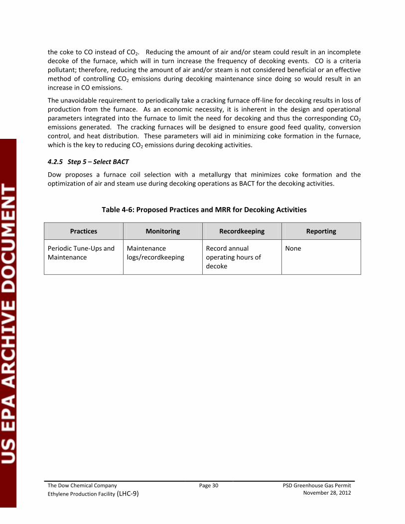
The Dow Chemical Company Page 30 PSD Greenhouse Gas Permit Ethylene Production Facility (LHC-9) November 28, 2012
the coke to CO instead of CO2. Reducing the amount of air and/or steam could result in an incomplete decoke of the furnace, which will in turn increase the frequency of decoking events. CO is a criteria pollutant; therefore, reducing the amount of air and/or steam is not considered beneficial or an effective method of controlling CO2 emissions during decoking maintenance since doing so would result in an increase in CO emissions.
The unavoidable requirement to periodically take a cracking furnace off-line for decoking results in loss of production from the furnace. As an economic necessity, it is inherent in the design and operational parameters integrated into the furnace to limit the need for decoking and thus the corresponding CO2 emissions generated. The cracking furnaces will be designed to ensure good feed quality, conversion control, and heat distribution. These parameters will aid in minimizing coke formation in the furnace, which is the key to reducing CO2 emissions during decoking activities.
4.2.5 Step 5 – Select BACT
Dow proposes a furnace coil selection with a metallurgy that minimizes coke formation and the optimization of air and steam use during decoking operations as BACT for the decoking activities.
Table 4-6: Proposed Practices and MRR for Decoking Activities
Practices Monitoring Recordkeeping Reporting
Periodic Tune-Ups and Maintenance
Maintenance logs/recordkeeping
Record annual operating hours of decoke
None
The Dow Chemical Company Page 31 PSD Greenhouse Gas Permit Ethylene Production Facility (LHC-9) November 28, 2012
4.4 BACT for Flare System
The small elevated flare is designed to control fugitive emissions from process compressor seals. There is also a continuous N2 and natural gas purge to maintain header velocity and heating value. The pressure-assisted flare manages excess off-gas from LHC-9 operations. This is a necessary pressure control mechanism to address changes in off-gas consumption by other consumer plants at the site. Fuel line purging to safely isolate LHC-9 cracking furnaces burners is routinely flared for OC2L9HH1 – OC2L9HH8. Additionally, there is a continuous natural gas purge to the flare to maintain header velocity. The flare’s pilots are fueled by low-carbon pipeline natural gas and are in operation 8,760 hours per year. Both flares will be subject to TCEQ HRVOC and Federal 40 CFR 60.18 requirements.
4.4.1 Step 1 – Identify Available Control Technologies
A search of the RBLC database did not identify any GHG control technologies for control devices such as the small elevated or pressure-assisted flares, particularly since the flares themselves are considered add-on control units. However, to expedite this permit issuance process, Dow considered the following technologies as potential GHG control measures for the flares at the LHC-9 facility:
1. Use of low-carbon assist gas
2. Good flare design and operation
3. Carbon Capture and Storage
4.4.1.1 Low-Carbon Assist Gas
The use of natural gas as assist gas is the lowest-carbon fuel available for the proposed project. Dow proposes to use natural gas for the flares’ pilot gas and as supplemental fuel, if needed, to maintain the appropriate vent stream heating value as required by applicable air quality regulations.
4.4.1.2 Good Flare Design and Operation
Good operating and maintenance practices for flares include appropriate maintenance of equipment (such as periodic flare tip maintenance) and operating within the recommended heating value and flare tip velocity as specified by its design. The use of good operating and maintenance practices results in longer life of the equipment and more efficient operation. Therefore, such practices indirectly reduce GHG emissions by supporting operation as designed by the flare manufacturer. Good flare design includes pilot flame monitoring, flow measurement, and monitoring/control of waste gas heating value.
4.4.1.3 Carbon Capture and Storage
The primary source of GHG emissions from a flare is the result of combustion of the hydrocarbon-containing gas stream in the flare. CCS requires separation of CO2 from the flare exhaust, compression of the CO2, and transportation to an injection/storage location.
4.4.2 Step 2 – Eliminate Technically Infeasible Options
4.4.2.1 Low-Carbon Assist Gas
Use of low-carbon assist gas is considered technically feasible.
4.4.2.2 Good Flare Design and Operation
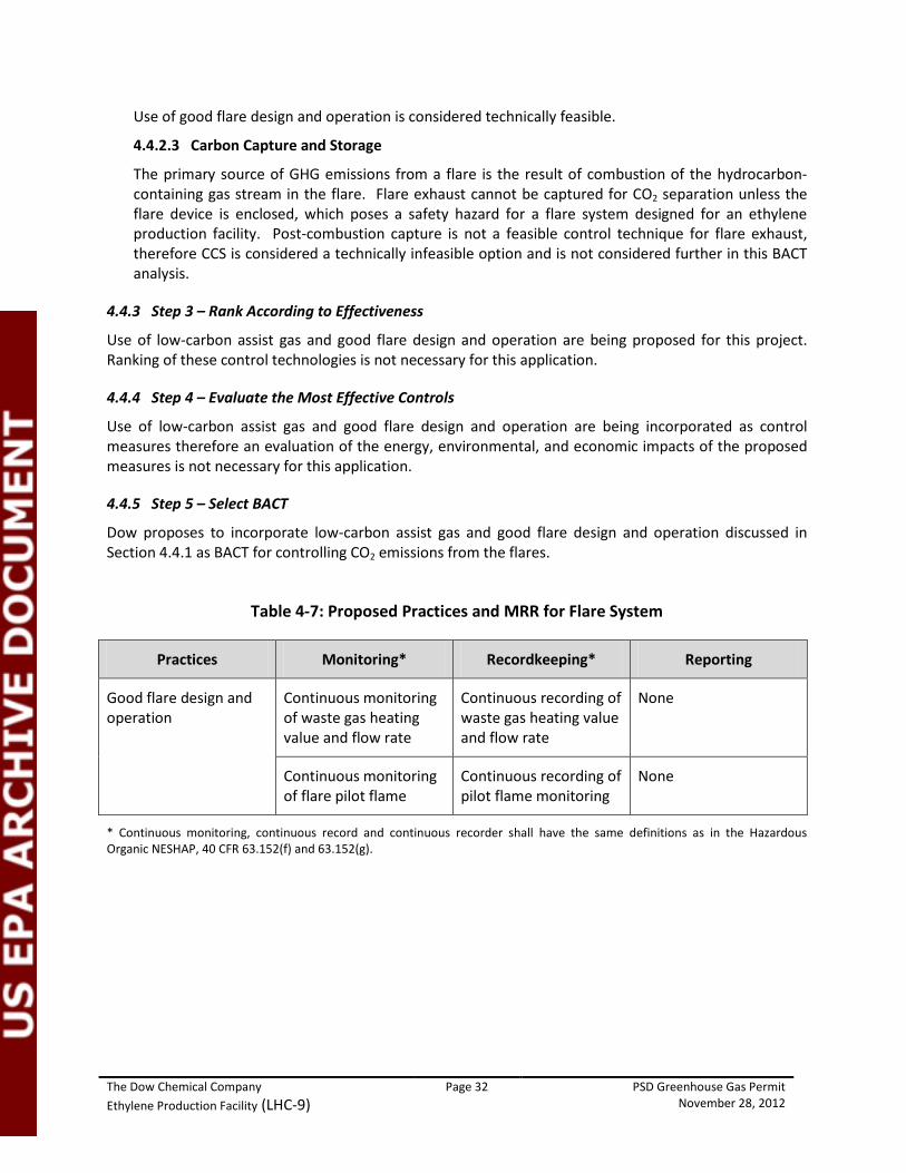
The Dow Chemical Company Page 32 PSD Greenhouse Gas Permit Ethylene Production Facility (LHC-9) November 28, 2012
Use of good flare design and operation is considered technically feasible.
4.4.2.3 Carbon Capture and Storage
The primary source of GHG emissions from a flare is the result of combustion of the hydrocarbon-containing gas stream in the flare. Flare exhaust cannot be captured for CO2 separation unless the flare device is enclosed, which poses a safety hazard for a flare system designed for an ethylene production facility. Post-combustion capture is not a feasible control technique for flare exhaust, therefore CCS is considered a technically infeasible option and is not considered further in this BACT analysis.
4.4.3 Step 3 – Rank According to Effectiveness
Use of low-carbon assist gas and good flare design and operation are being proposed for this project. Ranking of these control technologies is not necessary for this application.
4.4.4 Step 4 – Evaluate the Most Effective Controls
Use of low-carbon assist gas and good flare design and operation are being incorporated as control measures therefore an evaluation of the energy, environmental, and economic impacts of the proposed measures is not necessary for this application.
4.4.5 Step 5 – Select BACT
Dow proposes to incorporate low-carbon assist gas and good flare design and operation discussed in Section 4.4.1 as BACT for controlling CO2 emissions from the flares.
Table 4-7: Proposed Practices and MRR for Flare System
Practices Monitoring* Recordkeeping* Reporting
Good flare design and operation
Continuous monitoring of waste gas heating value and flow rate
Continuous recording of waste gas heating value and flow rate
None
Continuous monitoring of flare pilot flame
Continuous recording of pilot flame monitoring
None
* Continuous monitoring, continuous record and continuous recorder shall have the same definitions as in the Hazardous Organic NESHAP, 40 CFR 63.152(f) and 63.152(g).
The Dow Chemical Company Page 33 PSD Greenhouse Gas Permit Ethylene Production Facility (LHC-9) November 28, 2012
4.5 BACT for the Emergency Generators
The emergency generator engines proposed for use at the LHC-9 facility normally will operate at a low annual capacity factor (approximately one hour per week, and no more than 100 hours per year, per generator) in non-emergency use. Each engine is designed to use diesel fuel, stored in onsite tanks, so that emergency power is available for safe shutdown of the facility in the event of a power outage.
4.5.1 Step 1 – Identify Available Control Technologies
The RBLC database did not identify any add-on GHG control technologies for emergency generator diesel engines. Only good combustion practices were identified in the RBLC as BACT for emergency diesel generators and Dow considered this option in this analysis. Results of the RBLC search can be found in Appendix D.
Good combustion practices for compression ignition engines include appropriate maintenance of equipment (such as periodic testing as will be conducted weekly) and operating within the air to fuel ratio recommended by the manufacturer. Using good combustion practices results in longer life of the equipment and more efficient operation. Therefore, such practices indirectly reduce GHG emissions by supporting operation as designed by the manufacturer.
4.5.2 Step 2 – Eliminate Technically Infeasible Options
Use of good combustion practices is considered technically feasible.
4.5.3 Step 3 – Rank According to Effectiveness
Good combustion practices are the only control option identified in Step 2 and are being proposed for this project.
4.5.4 Step 4 – Evaluate the Most Effective Controls
Dow will incorporate good combustion practices as recommended by the emergency diesel generator manufacturer. An evaluation of the energy, environmental, and economic impacts of the proposed measure is not necessary for this application.
4.5.5 Step 5 – Select BACT
Dow proposes to incorporate good combustion practices discussed in Step 2 of Section 4.5 as BACT for controlling CO2 emissions from the emergency generators. Further, the new engines will be subject to the federal New Source Performance Standard (NSPS) for Stationary Compression Ignition Internal Combustion Engines (40 CFR Part 60, Subpart IIII). The NSPS has specific emissions standards for various pollutants which must be met during normal operation; therefore, the engine will meet or exceed BACT.
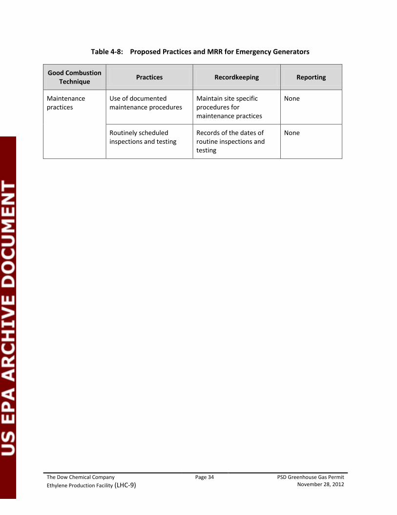
The Dow Chemical Company Page 34 PSD Greenhouse Gas Permit Ethylene Production Facility (LHC-9) November 28, 2012
Table 4-8: Proposed Practices and MRR for Emergency Generators
Good Combustion Technique Practices Recordkeeping Reporting
Maintenance practices
Use of documented maintenance procedures
Maintain site specific procedures for maintenance practices
None
Routinely scheduled inspections and testing
Records of the dates of routine inspections and testing
None
The Dow Chemical Company Page 35 PSD Greenhouse Gas Permit Ethylene Production Facility (LHC-9) November 28, 2012
4.6 BACT for Piping Fugitives
The proposed LHC-9 facility will include piping components with GHG fugitive emissions. Fugitive emissions of GHGs from piping will be associated with the plant fuel gas and natural gas lines at the unit. Other process lines in VOC service also may contain GHGs (methane). Emissions from these process lines have not been included in this BACT discussion as existing state and federal air regulations will require instrument leak detection and repair (LDAR) monitoring for any VOC containing process lines, which will also capture the methane component. This BACT discussion is therefore focused on control technologies for the fuel gas / natural gas piping components.
4.6.1 Step 1 – Identify Available Control Technologies
Piping fugitives may be controlled by various techniques, including:
1. Installation of leak-less technology to eliminate fugitive emissions sources;
2. Implementation of instrument leak detection and repair (LDAR) programs in accordance with applicable federal and state regulations and permit conditions;
3. Implementation of alternative monitoring using remote sensing technology such as infrared cameras; and
4. Implementation of audio/visual/olfactory (AVO) leak detection methods.
4.6.2 Step 2 – Eliminate Technically Infeasible Options
4.6.2.1 Leakless Technology
Leakless technology valves are used in situations where highly toxic or otherwise hazardous materials are present. These technologies cannot be repaired without a unit shutdown. Because fuel gas and natural gas are not considered highly toxic or hazardous materials, these fluids do not warrant the risk of unit shutdown for repair. Therefore leakless valve technology for fuel lines is considered technically infeasible.
4.6.2.2 Instrument LDAR Programs
Use of instrument LDAR is considered technically feasible.
4.6.2.3 Remote Sensing
Use of remote sensing measures is considered technically feasible.
4.6.2.4 AVO Monitoring
Emissions from leaking components can be identified through audible, visual, olfactory (AVO) methods. Natural gas and some process fluids may contain mercaptans, making them detectable by olfactory means. Therefore, use of as-observed AVO monitoring is considered technically feasible.
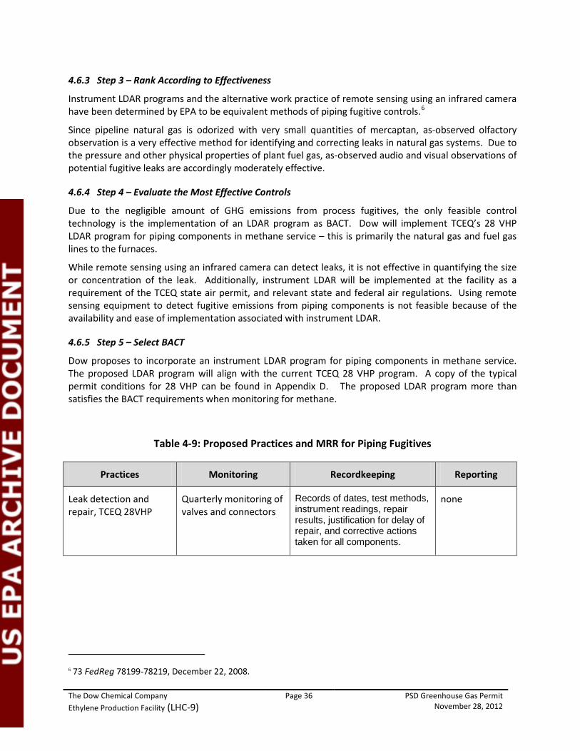
The Dow Chemical Company Page 36 PSD Greenhouse Gas Permit Ethylene Production Facility (LHC-9) November 28, 2012
4.6.3 Step 3 – Rank According to Effectiveness
Instrument LDAR programs and the alternative work practice of remote sensing using an infrared camera have been determined by EPA to be equivalent methods of piping fugitive controls.6
Since pipeline natural gas is odorized with very small quantities of mercaptan, as-observed olfactory observation is a very effective method for identifying and correcting leaks in natural gas systems. Due to the pressure and other physical properties of plant fuel gas, as-observed audio and visual observations of potential fugitive leaks are accordingly moderately effective.
4.6.4 Step 4 – Evaluate the Most Effective Controls
Due to the negligible amount of GHG emissions from process fugitives, the only feasible control technology is the implementation of an LDAR program as BACT. Dow will implement TCEQ’s 28 VHP LDAR program for piping components in methane service – this is primarily the natural gas and fuel gas lines to the furnaces.
While remote sensing using an infrared camera can detect leaks, it is not effective in quantifying the size or concentration of the leak. Additionally, instrument LDAR will be implemented at the facility as a requirement of the TCEQ state air permit, and relevant state and federal air regulations. Using remote sensing equipment to detect fugitive emissions from piping components is not feasible because of the availability and ease of implementation associated with instrument LDAR.
4.6.5 Step 5 – Select BACT
Dow proposes to incorporate an instrument LDAR program for piping components in methane service. The proposed LDAR program will align with the current TCEQ 28 VHP program. A copy of the typical permit conditions for 28 VHP can be found in Appendix D. The proposed LDAR program more than satisfies the BACT requirements when monitoring for methane.
Table 4-9: Proposed Practices and MRR for Piping Fugitives
Practices Monitoring Recordkeeping Reporting
Leak detection and repair, TCEQ 28VHP
Quarterly monitoring of valves and connectors
Records of dates, test methods, instrument readings, repair results, justification for delay of repair, and corrective actions taken for all components.
none
6 73 FedReg 78199-78219, December 22, 2008.
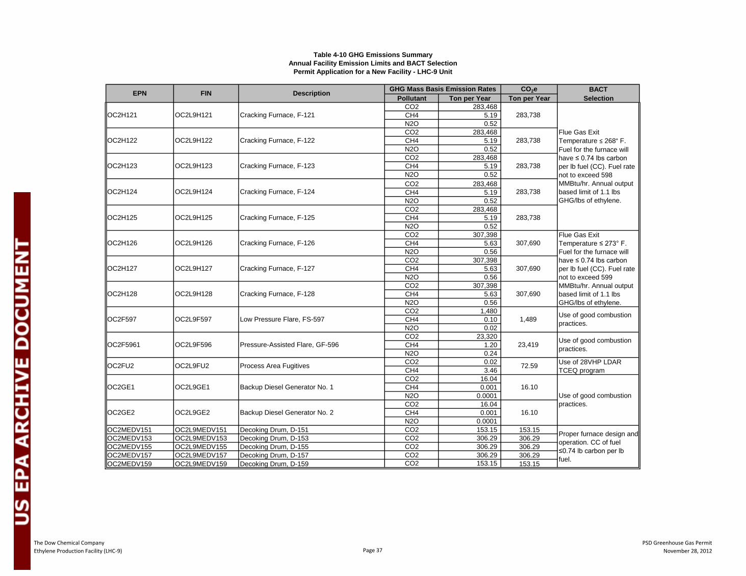
The Dow Chemical Company Ethylene Production Facility (LHC-9) Page 37
PSD Greenhouse Gas PermitNovember 28, 2012
CO2e BACTPollutant Ton per Year Ton per Year Selection
CO2 283,468 CH4 5.19 N2O 0.52 CO2 283,468 CH4 5.19 N2O 0.52 CO2 283,468 CH4 5.19 N2O 0.52 CO2 283,468 CH4 5.19 N2O 0.52 CO2 283,468 CH4 5.19 N2O 0.52 CO2 307,398 CH4 5.63 N2O 0.56 CO2 307,398 CH4 5.63 N2O 0.56 CO2 307,398 CH4 5.63 N2O 0.56 CO2 1,480 CH4 0.10 N2O 0.02 CO2 23,320 CH4 1.20 N2O 0.24 CO2 0.02 CH4 3.46 CO2 16.04 CH4 0.001 N2O 0.0001 CO2 16.04 CH4 0.001 N2O 0.0001
OC2MEDV151 OC2L9MEDV151 Decoking Drum, D-151 CO2 153.15 153.15OC2MEDV153 OC2L9MEDV153 Decoking Drum, D-153 CO2 306.29 306.29OC2MEDV155 OC2L9MEDV155 Decoking Drum, D-155 CO2 306.29 306.29OC2MEDV157 OC2L9MEDV157 Decoking Drum, D-157 CO2 306.29 306.29OC2MEDV159 OC2L9MEDV159 Decoking Drum, D-159 CO2 153.15 153.15
EPN FIN Description GHG Mass Basis Emission Rates
OC2H122 OC2L9H122 Cracking Furnace, F-122
OC2H123 OC2L9H123 Cracking Furnace, F-123
OC2H124 OC2L9H124 Cracking Furnace, F-124
OC2H125 OC2L9H125
Table 4-10 GHG Emissions SummaryAnnual Facility Emission Limits and BACT Selection
Permit Application for a New Facility - LHC-9 Unit
OC2H121 OC2L9H121 Cracking Furnace, F-121
Cracking Furnace, F-125
OC2H126 OC2L9H126 Cracking Furnace, F-126
OC2H127 OC2L9H127 Cracking Furnace, F-127
OC2L9GE1 Backup Diesel Generator No. 1
OC2F597 OC2L9F597 Low Pressure Flare, FS-597
OC2F5961 OC2L9F596 Pressure-Assisted Flare, GF-596
283,738
283,738
283,738
307,690
307,690
283,738
283,738
307,690
OC2GE2 OC2L9GE2 Backup Diesel Generator No. 2
OC2FU2 OC2L9FU2 Process Area Fugitives
1,489
23,419
72.59
16.10
16.10
OC2H128 OC2L9H128 Cracking Furnace, F-128
OC2GE1
Proper furnace design and operation. CC of fuel ≤0.74 lb carbon per lb fuel.
Use of good combustion practices.
Use of 28VHP LDAR TCEQ program
Flue Gas Exit Temperature ≤ 268° F. Fuel for the furnace will have ≤ 0.74 lbs carbon per lb fuel (CC). Fuel rate not to exceed 598 MMBtu/hr. Annual output based limit of 1.1 lbs GHG/lbs of ethylene.
Flue Gas Exit Temperature ≤ 273° F. Fuel for the furnace will have ≤ 0.74 lbs carbon per lb fuel (CC). Fuel rate not to exceed 599 MMBtu/hr. Annual output based limit of 1.1 lbs GHG/lbs of ethylene.
Use of good combustion practices.
Use of good combustion practices.
The Dow Chemical Company Page 38 PSD Greenhouse Gas Permit Ethylene Production Facility (LHC-9) November 28, 2012
SECTION 5.0 OTHER PSD REQUIREMENTS
5.1 Impacts Analysis
An impacts analysis is not being provided with this application in accordance with EPA's document PSD and Title V Permitting Guidance for Greenhouse Gases, March. 2011(Pages 47& 48):
“Since there are no NAAQS or PSD increments for GHGs, the requirements in sections 52.21(k) and 51.166(k) of EPA's regulations to demonstrate that a source does not cause or contribute to a violation of the NAAQS are not applicable to GHGs. Thus, we do not recommend that PSD applicants be required to model or conduct ambient monitoring for CO2 or GHGs”.
5.2 GHG Preconstruction Monitoring
A pre-construction monitoring analysis for GHG is not being provided with this application in accordance with EPA's document PSD and Title V Permitting Guidance for Greenhouse Gases, March. 2011(Page 48):
“Monitoring for GHGs is not required because EPA regulations provide an exemption in sections 52.21(i)(5)(iii) and 51.166(i)(5)(iii) for pollutants that are not listed in the appropriate section of the regulations, and GHGs are not currently included in that list. However, it should be noted that sections 52.21(m)(1)(ii) and 51.166(m)(1)(ii) of EPA’s regulations apply to pollutants for which no NAAQS exists. These provisions call for collection of air quality monitoring data “as the Administrator determines is necessary to assess ambient air quality for that pollutant in any (or the) area that the emissions of that pollutant would affect.” In the case of GHGs, the exemption in sections 52.21(i)(5)(iii) and 51.166(i)(5)(iii) is controlling since GHGs are not currently listed in the relevant paragraph. Nevertheless, EPA does not consider it necessary for applicants to gather monitoring data to assess ambient air quality for GHGs under section 52.21(m)(1)(ii), section 51.166(m)(1)(ii), or similar provisions that may be contained in state rules based on EPA’s rules. GHGs do not affect “ambient air quality” in the sense that EPA intended when these parts of EPA’s rules were initially drafted. Considering the nature of GHG emissions and their global impacts, EPA does not believe it is practical or appropriate to expect permitting authorities to collect monitoring data for purpose of assessing ambient air impacts of GHGs.”
5.3 Additional Impacts Analysis
A PSD additional impacts analysis is not being provided with this application in accordance with EPA's document PSD and Title V Permitting Guidance for Greenhouse Gases, March. 2011(Page 48):
“Furthermore, consistent with EPA's statement in the Tailoring Rule, EPA believes it is not necessary for applicants or permitting authorities to assess impacts from GHGs in the context of the additional impacts analysis or Class I area provisions of the PSD regulations for the following policy reasons. Although it is clear that GHG emissions contribute to global warming and other climate changes that result in impacts on the environment, including impacts on Class I areas and soils and vegetation due to the global scope of the problem, climate change modeling and evaluations of risks and impacts of GHG emissions is typically conducted for changes in emissions orders of magnitude larger than the emissions from individual projects that might be analyzed in PSD permit reviews. Quantifying the exact impacts attributable to a specific GHG source obtaining a permit in specific places and points would not be possible with current climate change modeling. Given these considerations, GHG emissions would serve as the more appropriate and
The Dow Chemical Company Page 39 PSD Greenhouse Gas Permit Ethylene Production Facility (LHC-9) November 28, 2012
credible proxy for assessing the impact of a given facility. Thus, EPA believes that the most practical way to address the considerations reflected in the Class I area and additional impacts analysis is to focus on reducing GHG emissions to the maximum extent. In light of these analytical challenges, compliance with the BACT analysis is the best technique that can be employed at present to satisfy the additional impacts analysis and Class I area requirements of the rules related to GHGs.”
5.4 Endangered Species Act
EPA permitting of this Project is a federal action requiring compliance with Section 7 of the Endangered Species Act (ESA). EPA Region 6 has determined that a biological assessment (BA) is required to determine whether a proposed activity under the authority of a Federal action agency is likely to adversely affect listed species, proposed species, or designated critical habitat. Dow has retained the services of URS Corporation to prepare a BA that evaluates the project’s Action Area for federally-protected species and/or their potential habitat and to provide an evaluation of the project’s potential to affect federally protected species. Dow will submit a separate report regarding the results of the BA once the assessments have been completed. The report is anticipated to be completed in February 2013.
5.5 Magnuson-Stevens Fishery Conservation and Management Reauthorization Act
EPA Region 6 has determined that the Project is subject to compliance and the provisions of the Magnuson-Stevens Fishery Conservation and Management Act (MSFCMA), as amended. The MSFCMA, as amended by the Sustainable Fisheries Act of 1996 (Public Law 104-267), requires Federal agencies to consult with the National Marine Fisheries Service (NMFS) on activities that may adversely affect Essential Fish Habitat (EFH). As defined by 16 USC 1802(10), EFH constitutes those aquatic and associated land areas, specifically enumerated as the water way substrate, water column, and water properties required for any life cycle stage for aquatic organisms. EPA has requested that an EFH Assessment be prepared for project’s in the vicinity of EFH or with the likelihood of impacting EFH. Dow has retained the services of URS Corporation to prepare an EFH Assessment to evaluate the potential for the Project to affect designated EFH area adjacent to the project. Dow will submit a separate report regarding the results of the EFH Assessment once the assessments have been completed. The report is anticipated to be completed in February 2013.
5.6 National Historic Preservation Act
EPA Region 6 has determined, in accordance with Advisory Council on Historic Preservation regulations pertaining to historic properties protection (36 CFR 800.4), that the project is subject to the provisions of Section 106 of the National Historic Preservation Act (NHPA) of 1966 (as amended). Section 106 of the NHPA requires federal agencies take into account the effect that an undertaking will have on historic properties. Historic properties are those included in, or eligible for inclusion in, the National Register of Historic Places (NRHP) and may include archeological sites, buildings, structures, sites, objects, and districts. Dow has retained URS Corporation to conduct the required cultural resources review, and will submit a separate cultural report for the results of that review. The purpose of the review is to identify any historic properties that might be adversely affected by the proposed undertaking. Dow will submit a separate report regarding the results of the cultural resources review once the assessments have been completed. The cultural report is anticipated to be completed in February 2013. The cultural report will aid in the EPA’s Section 106 consultation with the Texas Historical Commission.

The Dow Chemical Company PSD Greenhouse Gas Permit Ethylene Production Facility (LHC-9) November 28, 2012
Appendix A Forms
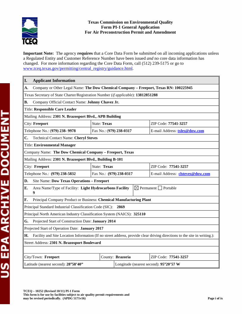
TCEQ – 10252 (Revised 10/11) PI-1 Form This form is for use by facilities subject to air quality permit requirements and may be revised periodically. (APDG 5171v16) Page i of ix
Texas Commission on Environmental Quality Form PI-1 General Application
For Air Preconstruction Permit and Amendment
Form PI-1 General Application Important Note: The agency requires that a Core Data Form be submitted on all incoming applications unless a Regulated Entity and Customer Reference Number have been issued and no core data information has changed. For more information regarding the Core Data Form, call (512) 239-5175 or go to www.tceq.texas.gov/permitting/central_registry/guidance.html. I. Applicant Information A. Company or Other Legal Name: The Dow Chemical Company – Freeport, Texas RN: 100225945
Texas Secretary of State Charter/Registration Number (if applicable): 13812851288
B. Company Official Contact Name: Johnny Chavez Jr.
Title: Responsible Care Leader
Mailing Address: 2301 N. Brazosport Blvd., APB Building
City: Freeport State: Texas ZIP Code: 77541-3257
Telephone No.: (979) 238- 9978 Fax No.: (979) 238-0317 E-mail Address: [email protected]
C. Technical Contact Name: Cheryl Steves
Title: Environmental Manager
Company Name: The Dow Chemical Company – Freeport, Texas
Mailing Address: 2301 N. Brazosport Blvd., Building B-101
City: Freeport State: Texas ZIP Code: 77541-3257
Telephone No.: (979) 238-5832 Fax No.: (979) 238-0317 E-mail Address: [email protected]
D. Site Name: Dow Texas Operations – Freeport
E. Area Name/Type of Facility: Light Hydrocarbons Facility 9
Permanent Portable
F. Principal Company Product or Business: Chemical Manufacturing Plant
Principal Standard Industrial Classification Code (SIC): 2869
Principal North American Industry Classification System (NAICS): 325110
G. Projected Start of Construction Date: January 2014
Projected Start of Operation Date: January 2017
H. Facility and Site Location Information (If no street address, provide clear driving directions to the site in writing.):
Street Address: 2301 N. Brazosport Boulevard
City/Town: Freeport County: Brazoria ZIP Code: 77541-3257
Latitude (nearest second): 28°58’40” Longitude (nearest second): 95°20’57 W
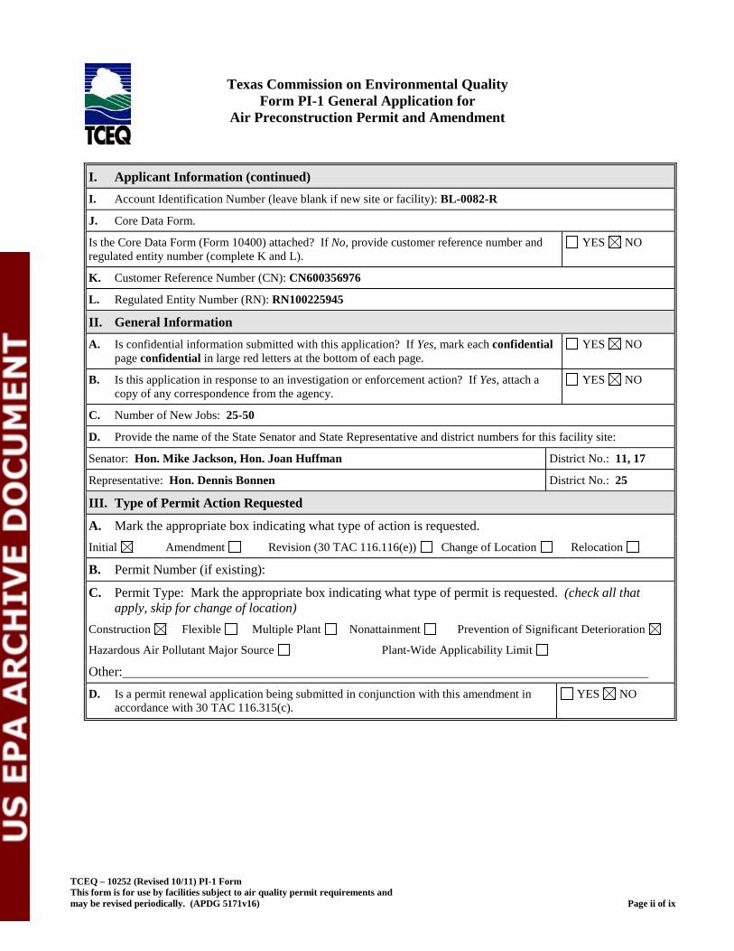
TCEQ – 10252 (Revised 10/11) PI-1 Form This form is for use by facilities subject to air quality permit requirements and may be revised periodically. (APDG 5171v16) Page ii of ix
Texas Commission on Environmental Quality
Form PI-1 General Application for Air Preconstruction Permit and Amendment
I. Applicant Information (continued) I. Account Identification Number (leave blank if new site or facility): BL-0082-R
J. Core Data Form.
Is the Core Data Form (Form 10400) attached? If No, provide customer reference number and regulated entity number (complete K and L).
YES NO
K. Customer Reference Number (CN): CN600356976
L. Regulated Entity Number (RN): RN100225945
II. General Information A. Is confidential information submitted with this application? If Yes, mark each confidential
page confidential in large red letters at the bottom of each page. YES NO
B. Is this application in response to an investigation or enforcement action? If Yes, attach a copy of any correspondence from the agency.
YES NO
C. Number of New Jobs: 25-50
D. Provide the name of the State Senator and State Representative and district numbers for this facility site:
Senator: Hon. Mike Jackson, Hon. Joan Huffman District No.: 11, 17
Representative: Hon. Dennis Bonnen District No.: 25
III. Type of Permit Action Requested
A. Mark the appropriate box indicating what type of action is requested. Initial Amendment Revision (30 TAC 116.116(e)) Change of Location Relocation
B. Permit Number (if existing):
C. Permit Type: Mark the appropriate box indicating what type of permit is requested. (check all that apply, skip for change of location)
Construction Flexible Multiple Plant Nonattainment Prevention of Significant Deterioration
Hazardous Air Pollutant Major Source Plant-Wide Applicability Limit
Other:
D. Is a permit renewal application being submitted in conjunction with this amendment in accordance with 30 TAC 116.315(c).
YES NO
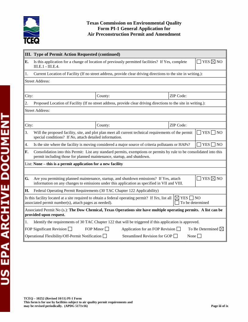
TCEQ – 10252 (Revised 10/11) PI-1 Form This form is for use by facilities subject to air quality permit requirements and may be revised periodically. (APDG 5171v16) Page iii of ix
Texas Commission on Environmental Quality Form PI-1 General Application for
Air Preconstruction Permit and Amendment
III. Type of Permit Action Requested (continued) E. Is this application for a change of location of previously permitted facilities? If Yes, complete
III.E.1 - III.E.4. YES NO
1. Current Location of Facility (If no street address, provide clear driving directions to the site in writing.):
Street Address:
City: County: ZIP Code:
2. Proposed Location of Facility (If no street address, provide clear driving directions to the site in writing.):
Street Address:
City: County: ZIP Code:
3. Will the proposed facility, site, and plot plan meet all current technical requirements of the permit special conditions? If No, attach detailed information.
YES NO
4. Is the site where the facility is moving considered a major source of criteria pollutants or HAPs? YES NO
F. Consolidation into this Permit: List any standard permits, exemptions or permits by rule to be consolidated into this permit including those for planned maintenance, startup, and shutdown.
List: None – this is a permit application for a new facility
G. Are you permitting planned maintenance, startup, and shutdown emissions? If Yes, attach information on any changes to emissions under this application as specified in VII and VIII.
YES NO
H. Federal Operating Permit Requirements (30 TAC Chapter 122 Applicability)
Is this facility located at a site required to obtain a federal operating permit? If Yes, list all associated permit number(s), attach pages as needed).
YES NO To be determined
Associated Permit No (s.): The Dow Chemical, Texas Operations site have multiple operating permits. A list can be provided upon request.
1. Identify the requirements of 30 TAC Chapter 122 that will be triggered if this application is approved.
FOP Significant Revision FOP Minor Application for an FOP Revision To Be Determined
Operational Flexibility/Off-Permit Notification Streamlined Revision for GOP None
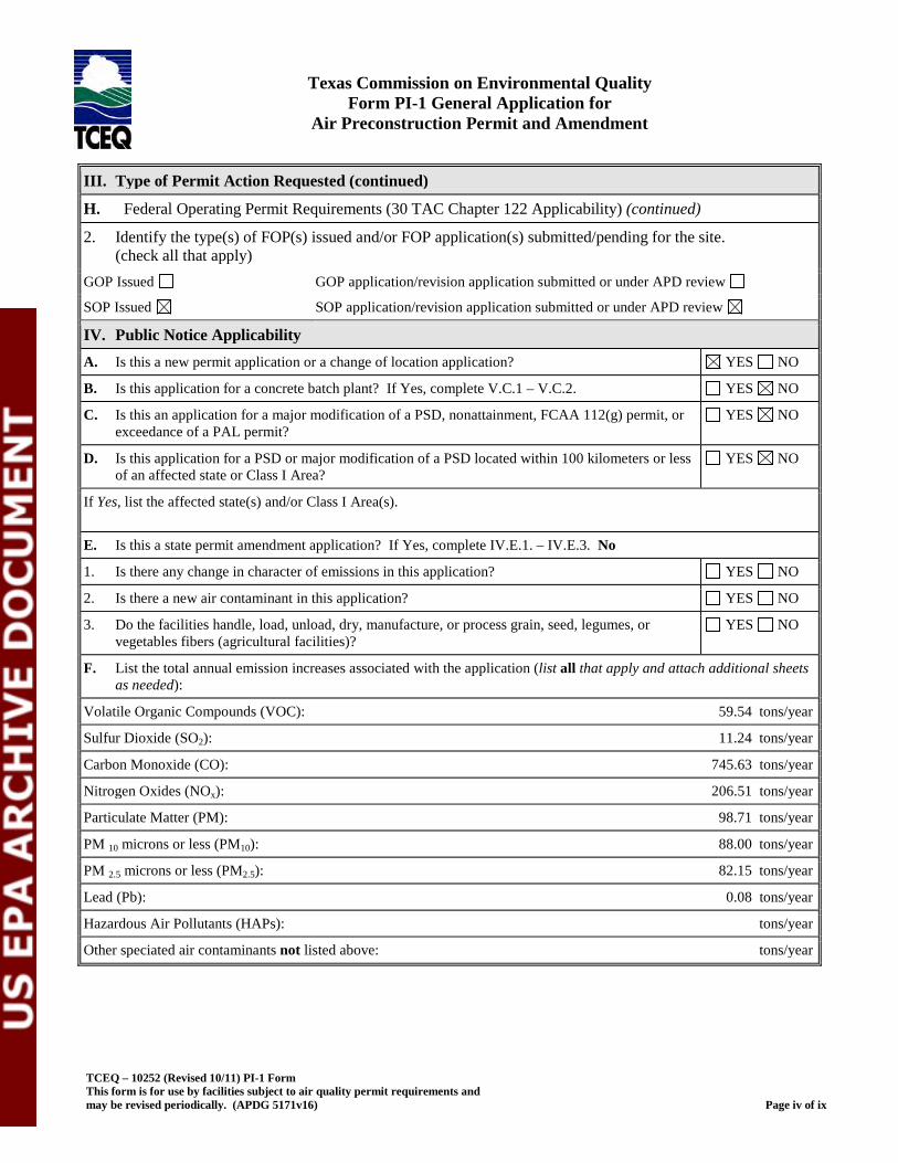
TCEQ – 10252 (Revised 10/11) PI-1 Form This form is for use by facilities subject to air quality permit requirements and may be revised periodically. (APDG 5171v16) Page iv of ix
Texas Commission on Environmental Quality Form PI-1 General Application for
Air Preconstruction Permit and Amendment
III. Type of Permit Action Requested (continued)
H. Federal Operating Permit Requirements (30 TAC Chapter 122 Applicability) (continued)
2. Identify the type(s) of FOP(s) issued and/or FOP application(s) submitted/pending for the site. (check all that apply)
GOP Issued GOP application/revision application submitted or under APD review
SOP Issued SOP application/revision application submitted or under APD review
IV. Public Notice Applicability A. Is this a new permit application or a change of location application? YES NO
B. Is this application for a concrete batch plant? If Yes, complete V.C.1 – V.C.2. YES NO
C. Is this an application for a major modification of a PSD, nonattainment, FCAA 112(g) permit, or exceedance of a PAL permit?
YES NO
D. Is this application for a PSD or major modification of a PSD located within 100 kilometers or less of an affected state or Class I Area?
YES NO
If Yes, list the affected state(s) and/or Class I Area(s).
E. Is this a state permit amendment application? If Yes, complete IV.E.1. – IV.E.3. No
1. Is there any change in character of emissions in this application? YES NO
2. Is there a new air contaminant in this application? YES NO
3. Do the facilities handle, load, unload, dry, manufacture, or process grain, seed, legumes, or vegetables fibers (agricultural facilities)?
YES NO
F. List the total annual emission increases associated with the application (list all that apply and attach additional sheets as needed):
Volatile Organic Compounds (VOC): 59.54 tons/year
Sulfur Dioxide (SO2): 11.24 tons/year
Carbon Monoxide (CO): 745.63 tons/year
Nitrogen Oxides (NOx): 206.51 tons/year
Particulate Matter (PM): 98.71 tons/year
PM 10 microns or less (PM10): 88.00 tons/year
PM 2.5 microns or less (PM2.5): 82.15 tons/year
Lead (Pb): 0.08 tons/year
Hazardous Air Pollutants (HAPs): tons/year
Other speciated air contaminants not listed above: tons/year
TCEQ – 10252 (Revised 10/11) PI-1 Form This form is for use by facilities subject to air quality permit requirements and may be revised periodically. (APDG 5171v16) Page v of ix
Texas Commission on Environmental Quality
Form PI-1 General Application for Air Preconstruction Permit and Amendment
V. Public Notice Information (complete if applicable)
A. Public Notice Contact Name: Cheryl Steves
Title: Environmental Manager
Mailing Address: 2301 N. Brazosport Blvd., Building B-101
City: Freeport State: Texas ZIP Code: 77541
Telephone No.: (979) 238- 5832
B. Name of the Public Place: Freeport Public Library
Physical Address (No P.O. Boxes): 410 Brazosport Blvd.
City: Freeport County: Brazoria ZIP Code: 77541
The public place has granted authorization to place the application for public viewing and copying.
YES NO
The public place has internet access available for the public. YES NO
C. Concrete Batch Plants, PSD, and Nonattainment Permits
1. County Judge Information (For Concrete Batch Plants and PSD and/or Nonattainment Permits) for this facility site.
The Honorable: E. J. “Joe” King
Mailing Address: 111 East Locust Street
City: Angleton State: Texas ZIP Code: 77515
2. Is the facility located in a municipality or an extraterritorial jurisdiction of a municipality? (For Concrete Batch Plants)
YES NO
Presiding Officers Name(s):
Title:
Mailing Address:
City: State: ZIP Code:
3. Provide the name, mailing address of the chief executive of the city for the location where the facility is or will be located.
Chief Executive: Mayor Norma Moreno Garcia
Mailing Address: 200 West 2nd Street
City: Freeport State: Texas ZIP Code: 77541
TCEQ – 10252 (Revised 10/11) PI-1 Form This form is for use by facilities subject to air quality permit requirements and may be revised periodically. (APDG 5171v16) Page vi of ix
Texas Commission on Environmental Quality
Form PI-1 General Application for Air Preconstruction Permit and Amendment
V. Public Notice Information (complete if applicable) (continued) 4. Provide the name, mailing address of the Indian Governing Body for the location where the facility is or will be located.
(continued)
Name of the Indian Governing Body:
Title:
Mailing Address:
City: State: ZIP Code:
D. Bilingual Notice
Is a bilingual program required by the Texas Education Code in the School District? YES NO
Are the children who attend either the elementary school or the middle school closest to your facility eligible to be enrolled in a bilingual program provided by the district?
YES NO
If Yes, list which languages are required by the bilingual program? Spanish
VI. Small Business Classification (Required) A. Does this company (including parent companies and subsidiary companies) have fewer than 100
employees or less than $6 million in annual gross receipts? YES NO
B. Is the site a major stationary source for federal air quality permitting? YES NO
C. Are the site emissions of any regulated air pollutant greater than or equal to 50 tpy? YES NO
D. Are the site emissions of all regulated air pollutants combined less than 75 tpy? YES NO
VII. Technical Information A. The following information must be submitted with your Form PI-1 (this is just a checklist to make sure you have
included everything)
1. Current Area Map
2. Plot Plan
3. Existing Authorizations
4. Process Flow Diagram
5. Process Description
6. Maximum Emissions Data and Calculations
7. Air Permit Application Tables
a. Table 1(a) (Form 10153) entitled, Emission Point Summary
b. Table 2 (Form 10155) entitled, Material Balance
c. Other equipment, process or control device tables
TCEQ – 10252 (Revised 10/11) PI-1 Form This form is for use by facilities subject to air quality permit requirements and may be revised periodically. (APDG 5171v16) Page vii of ix
Texas Commission on Environmental Quality
Form PI-1 General Application for Air Preconstruction Permit and Amendment
VII. Technical Information B. Are any schools located within 3,000 feet of this facility? YES NO
C. Maximum Operating Schedule:
Hours: 24 Day(s): 7 Week(s): 52 Year(s):
Seasonal Operation? If Yes, please describe in the space provide below. YES NO
D. Have the planned MSS emissions been previously submitted as part of an emissions inventory? YES NO
Provide a list of each planned MSS facility or related activity and indicate which years the MSS activities have been included in the emissions inventories. Attach pages as needed.
E. Does this application involve any air contaminants for which a disaster review is required? YES NO
F. Does this application include a pollutant of concern on the Air Pollutant Watch List (APWL)? YES NO
VIII. State Regulatory Requirements Applicants must demonstrate compliance with all applicable state regulations to obtain a permit or amendment. The application must contain detailed attachments addressing applicability or non applicability; identify state regulations; show how requirements are met; and include compliance demonstrations.
A. Will the emissions from the proposed facility protect public health and welfare, and comply with all rules and regulations of the TCEQ?
YES NO
B. Will emissions of significant air contaminants from the facility be measured? YES NO
C. Is the Best Available Control Technology (BACT) demonstration attached? YES NO
D. Will the proposed facilities achieve the performance represented in the permit application as demonstrated through recordkeeping, monitoring, stack testing, or other applicable methods?
YES NO
IX. Federal Regulatory Requirements Applicants must demonstrate compliance with all applicable federal regulations to obtain a permit or amendment The application must contain detailed attachments addressing applicability or non applicability; identify federal regulation subparts; show how requirements are met; and include compliance demonstrations.
A. Does Title 40 Code of Federal Regulations Part 60, (40 CFR Part 60) New Source Performance Standard (NSPS) apply to a facility in this application?
YES NO
B. Does 40 CFR Part 61, National Emissions Standard for Hazardous Air Pollutants (NESHAP) apply to a facility in this application?
YES NO
C. Does 40 CFR Part 63, Maximum Achievable Control Technology (MACT) standard apply to a facility in this application?
YES NO
TCEQ – 10252 (Revised 10/11) PI-1 Form This form is for use by facilities subject to air quality permit requirements and may be revised periodically. (APDG 5171v16) Page viii of ix
Texas Commission on Environmental Quality Form PI-1 General Application for
Air Preconstruction Permit and Amendment
IX. Federal Regulatory Requirements Applicants must demonstrate compliance with all applicable federal regulations to obtain a permit or amendment The application must contain detailed attachments addressing applicability or non applicability; identify federal regulation subparts; show how requirements are met; and include compliance demonstrations.
D. Do nonattainment permitting requirements apply to this application? YES NO
E. Do prevention of significant deterioration permitting requirements apply to this application? YES NO
F. Do Hazardous Air Pollutant Major Source [FCAA 112(g)] requirements apply to this application?
YES NO
G. Is a Plant-wide Applicability Limit permit being requested? YES NO
X. Professional Engineer (P.E.) Seal Is the estimated capital cost of the project greater than $2 million dollars? YES NO
If Yes, submit the application under the seal of a Texas licensed P.E.
XI. Permit Fee Information Check, Money Order, Transaction Number ,ePay Voucher Number: Fee Amount: $ 75,000
Company name on check: The Dow Chemical Company Paid online?: YES NO
Is a copy of the check or money order attached to the original submittal of this application? YES NO N/A
Is a Table 30 (Form 10196) entitled, Estimated Capital Cost and Fee Verification, attached? YES NO N/A
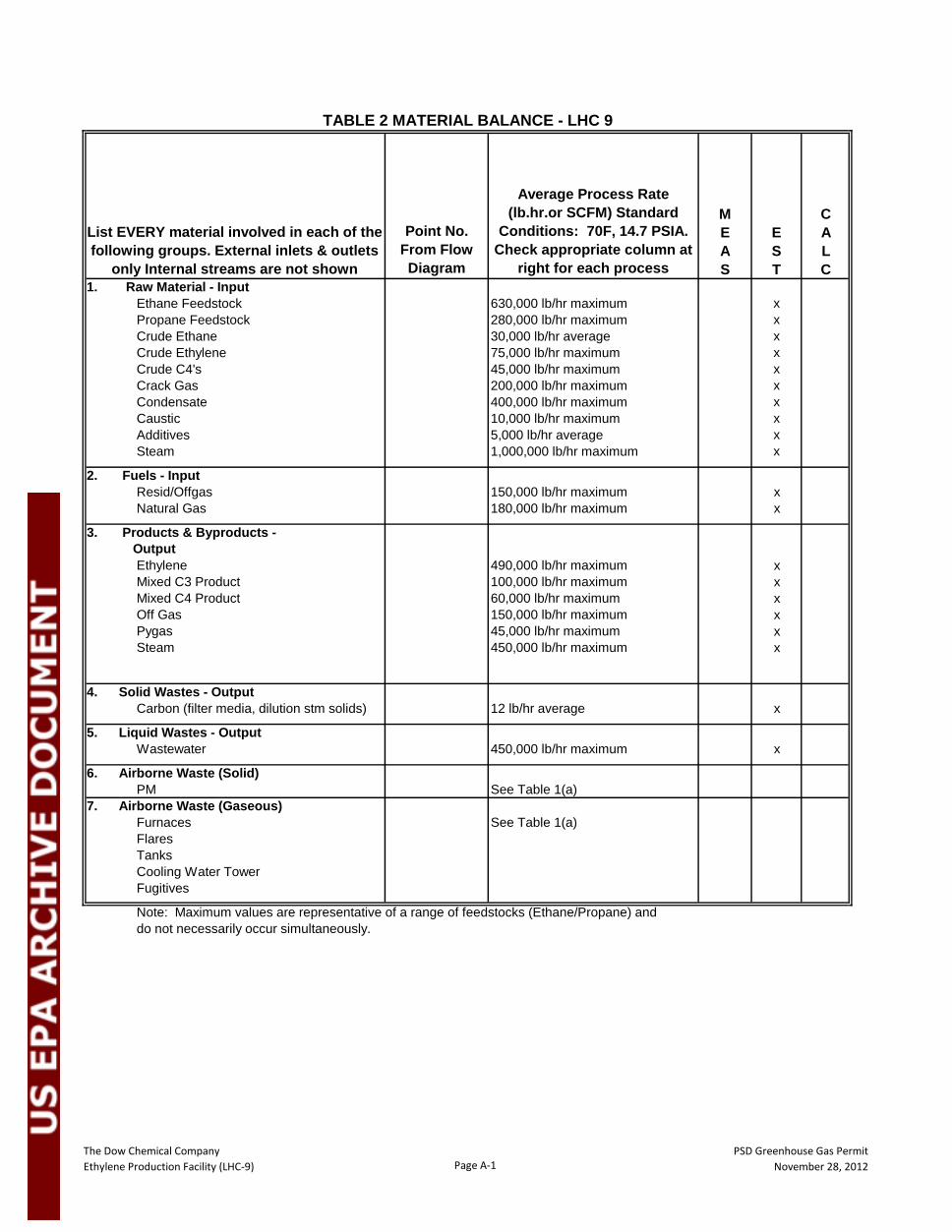
The Dow Chemical Company Ethylene Production Facility (LHC-9) Page A-1
PSD Greenhouse Gas PermitNovember 28, 2012
Point No. From Flow Diagram
Average Process Rate (lb.hr.or SCFM) Standard
Conditions: 70F, 14.7 PSIA. Check appropriate column at
right for each process
MEAS
EST
CALC
1. Raw Material - Input Ethane Feedstock 630,000 lb/hr maximum x Propane Feedstock 280,000 lb/hr maximum x Crude Ethane 30,000 lb/hr average x Crude Ethylene 75,000 lb/hr maximum x
Crude C4's 45,000 lb/hr maximum xCrack Gas 200,000 lb/hr maximum x
Condensate 400,000 lb/hr maximum xCaustic 10,000 lb/hr maximum xAdditives 5,000 lb/hr average xSteam 1,000,000 lb/hr maximum x
2. Fuels - Input Resid/Offgas 150,000 lb/hr maximum x
Natural Gas 180,000 lb/hr maximum x
3. Products & Byproducts - Output
Ethylene 490,000 lb/hr maximum xMixed C3 Product 100,000 lb/hr maximum xMixed C4 Product 60,000 lb/hr maximum xOff Gas 150,000 lb/hr maximum xPygas 45,000 lb/hr maximum xSteam 450,000 lb/hr maximum x
4. Solid Wastes - OutputCarbon (filter media, dilution stm solids) 12 lb/hr average x
5. Liquid Wastes - OutputWastewater 450,000 lb/hr maximum x
6. Airborne Waste (Solid)PM See Table 1(a)
7. Airborne Waste (Gaseous)Furnaces See Table 1(a)FlaresTanksCooling Water TowerFugitives
Note: Maximum values are representative of a range of feedstocks (Ethane/Propane) and do not necessarily occur simultaneously.
TABLE 2 MATERIAL BALANCE - LHC 9
List EVERY material involved in each of the following groups. External inlets & outlets
only Internal streams are not shown
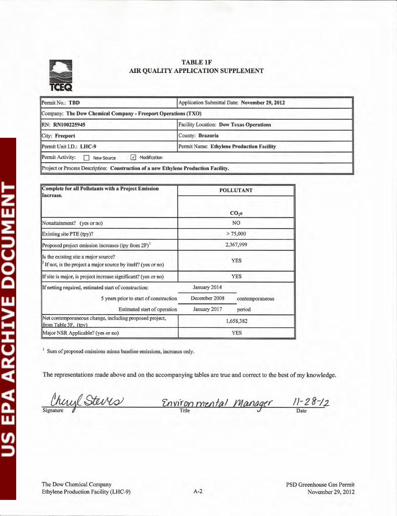
Date
TABLE IFAIR QUALITY APPLICATION SUPPLEMENT
Permit No.: TBD Application Submittal Date: November 29, 2012
Company: The Dow Chemical Company - Freeport Operations (TXO)
~: ~100225945 Facility Location: Dow Texas Operations
City: Freeport County: Brazoria
Permit Unit I.D.: LHC-9 Permit Name: Ethylene Production Facility
Permit Activity: 0 New Source El Modification
Project or Process Description: Construction of a new Ethylene Production Facility.
Complete for all Pollutants with a Project Emission POLLUTANTIncrease.
C02e
INonattainment? (yes or no) NO
Existing site PTE (tpy)? >75,000
Proposed project emission increases (tpy from 2F) I 2,367,999
Is the existing site a major source?YES
2 Ifnot, is the project a major source by itself? (yes or no)
If site is major, is project increase significant? (yes or no) YES
If netting required, estimated start of construction: January 2014
5 years prior to start of construction December 2008 contemporaneous
Estimated start of operation January 2017 period
Net contemporaneous change, including proposed project, 1,658,382from Table 3F. (tnv)Major NSR Applicable? (yes or no) YES
I Sum of proposed emissions minus baseline emissions, increases only.
The representations made above and on the accompanying tables are true and correct to the best of my knowledge.
The Dow Chemical CompanyEthylene Production Facility (LHC-9) A-2
PSD Greenhouse Gas PermitNovember 29,2012
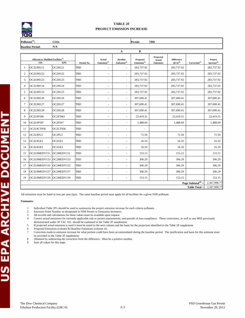
Pollutant(1): CO2e Permit: TBD
Baseline Period: N/AA B
FIN EPN
1 OC2L9H121 OC2H121 TBD - - 283,737.92 283,737.92 283,737.92
2 OC2L9H122 OC2H122 TBD - - 283,737.92 283,737.92 283,737.92
3 OC2L9H123 OC2H123 TBD - - 283,737.92 283,737.92 283,737.92
4 OC2L9H124 OC2H124 TBD - - 283,737.92 283,737.92 283,737.92
5 OC2L9H125 OC2H125 TBD - - 283,737.92 283,737.92 283,737.92
6 OC2L9H126 OC2H126 TBD - - 307,690.41 307,690.41 307,690.41
7 OC2L9H127 OC2H127 TBD - - 307,690.41 307,690.41 307,690.41
8 OC2L9H128 OC2H128 TBD - - 307,690.41 307,690.41 307,690.41
9 OC2L9F596 OC2F5961 TBD - - 23,419.31 23,419.31 23,419.31
10 OC2L9F597 OC2F597 TBD - - 1,488.69 1,488.69 1,488.69
11 OC2L9CT936 OC2CT936 TBD - - - - -
12 OC2L9FU2 OC2FU2 TBD - - 72.59 72.59 72.59
13 OC2L9GE1 OC2GE1 TBD - - 16.10 16.10 16.10
14 OC2L9GE2 OC2GE2 TBD - - 16.10 16.10 16.10
15 OC2L9MEDV151 OC2MEDV151 TBD - - 153.15 153.15 153.15
16 OC2L9MEDV153 OC2MEDV153 TBD - - 306.29 306.29 306.29
17 OC2L9MEDV155 OC2MEDV155 TBD - - 306.29 306.29 306.29
18 OC2L9MEDV157 OC2MEDV157 TBD - - 306.29 306.29 306.29
19 OC2L9MEDV159 OC2MEDV159 TBD - - 153.15 153.15 153.15
Page Subtotal(9) = 2,367,998.77Table Total = 2,367,998.77
All emissions must be listed in tons per year (tpy). The same baseline period must apply for all facilities for a given NSR pollutant.
Footnotes:
1234
567
89
TABLE 2FPROJECT EMISSION INCREASE
Affected or Modified Facilities(2)
Permit No.Actual
Emissions(3)Baseline
Emissions(4)Proposed
Emissions(5)
ProjectedActual
EmissionsDifference
(B-A)(6) Correction(7)Project
Increase(8)
Individual Table 2F's should be used to summarize the project emission increase for each criteria pollutant.Emission Point Number as designated in NSR Permit or Emissions Inventory.All records and calculations for these values must be available upon request.Correct actual emissions for currently applicable rule or permit requirements, and periods of non-compliance. These corrections, as well as any MSS previouslydemonstrated under 30 TAC 101, should be explained in the Table 2F supplement.If projected actual emission is used it must be noted in the next column and the basis for the projection identified in the Table 2F supplement.Proposed Emissions (column B) Baseline Emissions (column A).Correction made to emission increase for what portion could have been accommodated during the baseline period. The justification and basis for this estimate mustbe provided in the Table 2F supplement.Obtained by subtracting the correction from the difference. Must be a positive number.Sum all values for this page.
The Dow Chemical CompanyEthylene Production Facility (LHC-9) A-3
PSD Greenhouse Gas PermitNovember 29, 2012
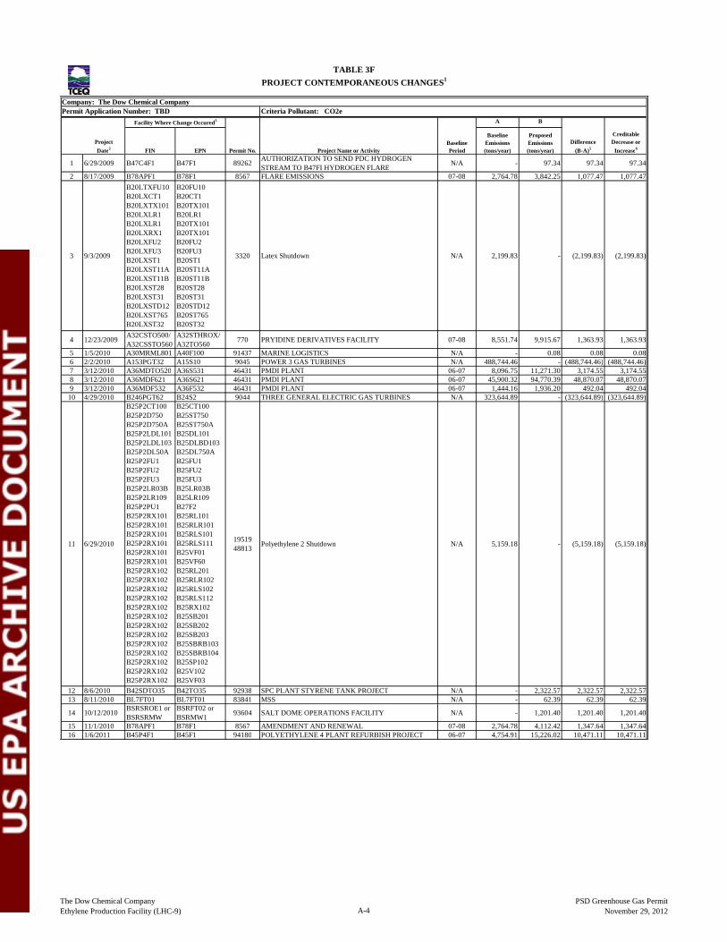
Company: The Dow Chemical CompanyPermit Application Number: TBD Criteria Pollutant: CO2e
A B
ProjectDate2 FIN EPN Permit No. Project Name or Activity
BaselinePeriod
BaselineEmissions(tons/year)
ProposedEmissions(tons/year)
Difference(B-A)5
CreditableDecrease or
Increase6
1 6/29/2009 B47C4F1 B47F1 89262 AUTHORIZATION TO SEND PDC HYDROGENSTREAM TO B47FI HYDROGEN FLARE N/A - 97.34 97.34 97.34
2 8/17/2009 B78APF1 B78F1 8567 FLARE EMISSIONS 07-08 2,764.78 3,842.25 1,077.47 1,077.47
3 9/3/2009
B20LTXFU10B20LXCT1B20LXTX101B20LXLR1B20LXLR1B20LXRX1B20LXFU2B20LXFU3B20LXST1B20LXST11AB20LXST11BB20LXST28B20LXST31B20LXSTD12B20LXST765B20LXST32
B20FU10B20CT1B20TX101B20LR1B20TX101B20TX101B20FU2B20FU3B20ST1B20ST11AB20ST11BB20ST28B20ST31B20STD12B20ST765B20ST32
3320 Latex Shutdown N/A 2,199.83 - (2,199.83) (2,199.83)
4 12/23/2009 A32CSTO500/A32CSSTO560
A32STHROX/A32TO560 770 PRYIDINE DERIVATIVES FACILITY 07-08 8,551.74 9,915.67 1,363.93 1,363.93
5 1/5/2010 A30MRML801 A40F100 91437 MARINE LOGISTICS N/A - 0.08 0.08 0.086 2/2/2010 A153PGT32 A15S10 9045 POWER 3 GAS TURBINES N/A 488,744.46 - (488,744.46) (488,744.46)7 3/12/2010 A36MDTO520 A36S531 46431 PMDI PLANT 06-07 8,096.75 11,271.30 3,174.55 3,174.558 3/12/2010 A36MDF621 A36S621 46431 PMDI PLANT 06-07 45,900.32 94,770.39 48,870.07 48,870.079 3/12/2010 A36MDF532 A36F532 46431 PMDI PLANT 06-07 1,444.16 1,936.20 492.04 492.04
10 4/29/2010 B246PGT62 B24S2 9044 THREE GENERAL ELECTRIC GAS TURBINES N/A 323,644.89 - (323,644.89) (323,644.89)
11 6/29/2010
B25P2CT100B25P2D750B25P2D750AB25P2LDL101B25P2LDL103B25P2DL50AB25P2FU1B25P2FU2B25P2FU3B25P2LR03BB25P2LR109B25P2PU1B25P2RX101B25P2RX101B25P2RX101B25P2RX101B25P2RX101B25P2RX101B25P2RX102B25P2RX102B25P2RX102B25P2RX102B25P2RX102B25P2RX102B25P2RX102B25P2RX102B25P2RX102B25P2RX102B25P2RX102B25P2RX102B25P2RX102B25P2RX102
B25CT100B25ST750B25ST750AB25DL101B25DLBD103B25DL750AB25FU1B25FU2B25FU3B25LR03BB25LR109B27F2B25RL101B25RLR101B25RLS101B25RLS111B25VF01B25VF60B25RL201B25RLR102B25RLS102B25RLS112B25RX102B25SB201B25SB202B25SB203B25SBRB103B25SBRB104B25SP102B25V102B25VF03B25VF60
1951948813 Polyethylene 2 Shutdown N/A 5,159.18 - (5,159.18) (5,159.18)
12 8/6/2010 B42SDTO35 B42TO35 92938 SPC PLANT STYRENE TANK PROJECT N/A - 2,322.57 2,322.57 2,322.5713 8/11/2010 BL7FT01 BL7FT01 83841 MSS N/A - 62.39 62.39 62.39
14 10/12/2010 BSRSROE1 orBSRSRMW
BSRFT02 orBSRMW1 93604 SALT DOME OPERATIONS FACILITY N/A - 1,201.40 1,201.40 1,201.40
15 11/1/2010 B78APF1 B78F1 8567 AMENDMENT AND RENEWAL 07-08 2,764.78 4,112.42 1,347.64 1,347.6416 1/6/2011 B45P4F1 B45F1 94180 POLYETHYLENE 4 PLANT REFURBISH PROJECT 06-07 4,754.91 15,226.02 10,471.11 10,471.11
PROJECT CONTEMPORANEOUS CHANGES1
Facility Where Change Occured3
TABLE 3F
The Dow Chemical CompanyEthylene Production Facility (LHC-9) A-4
PSD Greenhouse Gas PermitNovember 29, 2012
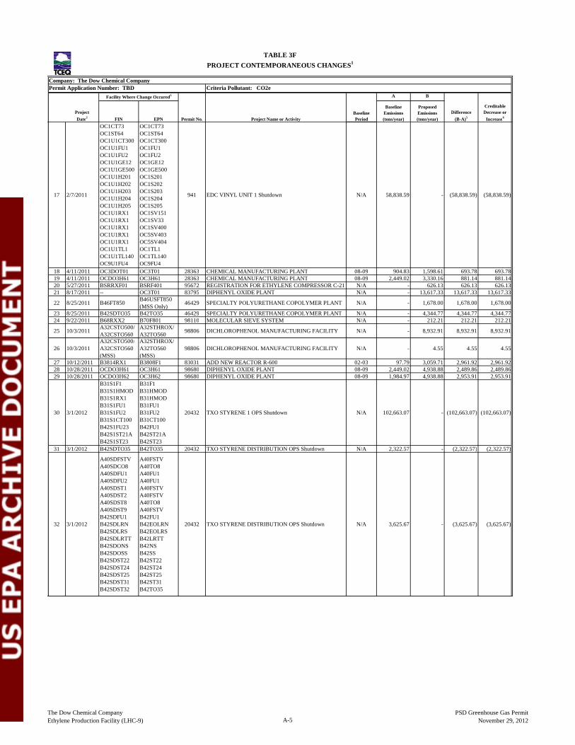
Company: The Dow Chemical CompanyPermit Application Number: TBD Criteria Pollutant: CO2e
A B
ProjectDate2 FIN EPN Permit No. Project Name or Activity
BaselinePeriod
BaselineEmissions(tons/year)
ProposedEmissions(tons/year)
Difference(B-A)5
CreditableDecrease or
Increase6
PROJECT CONTEMPORANEOUS CHANGES1
Facility Where Change Occured3
TABLE 3F
17 2/7/2011
OC1CT73OC1ST64OC1U1CT300OC1U1FU1OC1U1FU2OC1U1GE12OC1U1GE500OC1U1H201OC1U1H202OC1U1H203OC1U1H204OC1U1H205OC1U1RX1OC1U1RX1OC1U1RX1OC1U1RX1OC1U1RX1OC1U1TL1OC1U1TL140OC9U1FU4
OC1CT73OC1ST64OC1CT300OC1FU1OC1FU2OC1GE12OC1GE500OC1S201OC1S202OC1S203OC1S204OC1S205OC1SV151OC1SV33OC1SV400OC5SV403OC5SV404OC1TL1OC1TL140OC9FU4
941 EDC VINYL UNIT 1 Shutdown N/A 58,838.59 - (58,838.59) (58,838.59)
18 4/11/2011 OC3DOT01 OC3T01 28363 CHEMICAL MANUFACTURING PLANT 08-09 904.83 1,598.61 693.78 693.7819 4/11/2011 OCDO3H61 OC3H61 28363 CHEMICAL MANUFACTURING PLANT 08-09 2,449.02 3,330.16 881.14 881.1420 5/27/2011 BSRRXF01 BSRF401 95672 REGISTRATION FOR ETHYLENE COMPRESSOR C-21 N/A - 626.13 626.13 626.1321 8/17/2011 -- OC3T01 83795 DIPHENYL OXIDE PLANT N/A - 13,617.33 13,617.33 13,617.33
22 8/25/2011 B46FT850 B46USFT850(MSS Only) 46429 SPECIALTY POLYURETHANE COPOLYMER PLANT N/A - 1,678.00 1,678.00 1,678.00
23 8/25/2011 B42SDTO35 B42TO35 46429 SPECIALTY POLYURETHANE COPOLYMER PLANT N/A - 4,344.77 4,344.77 4,344.7724 9/22/2011 B68RXX2 B70F801 98110 MOLECULAR SIEVE SYSTEM N/A - 212.21 212.21 212.21
25 10/3/2011 A32CSTO500/A32CSTO560
A32STHROX/A32TO560 98806 DICHLOROPHENOL MANUFACTURING FACILITY N/A - 8,932.91 8,932.91 8,932.91
26 10/3/2011A32CSTO500/A32CSTO560(MSS)
A32STHROX/A32TO560(MSS)
98806 DICHLOROPHENOL MANUFACTURING FACILITY N/A - 4.55 4.55 4.55
27 10/12/2011 B3814RX1 B3808F1 83031 ADD NEW REACTOR R-600 02-03 97.79 3,059.71 2,961.92 2,961.9228 10/28/2011 OCDO3H61 OC3H61 98680 DIPHENYL OXIDE PLANT 08-09 2,449.02 4,938.88 2,489.86 2,489.8629 10/28/2011 OCDO3H62 OC3H62 98680 DIPHENYL OXIDE PLANT 08-09 1,984.97 4,938.88 2,953.91 2,953.91
30 3/1/2012
B31S1F1B31S1HMODB31S1RX1B31S1FU1B31S1FU2B31S1CT100B42S1FU23B42S1ST21AB42S1ST23
B31F1B31HMODB31HMODB31FU1B31FU2B31CT100B42FU1B42ST21AB42ST23
20432 TXO STYRENE 1 OPS Shutdown N/A 102,663.07 - (102,663.07) (102,663.07)
31 3/1/2012 B42SDTO35 B42TO35 20432 TXO STYRENE DISTRIBUTION OPS Shutdown N/A 2,322.57 - (2,322.57) (2,322.57)
32 3/1/2012
A40SDFSTVA40SDCO8A40SDFU1A40SDFU2A40SDST1A40SDST2A40SDST8A40SDST9B42SDFU1B42SDLRNB42SDLRSB42SDLRTTB42SDONSB42SDOSSB42SDST22B42SDST24B42SDST25B42SDST31B42SDST32
A40FSTVA40TO8A40FU1A40FU1A40FSTVA40FSTVA40TO8A40FSTVB42FU1B42EOLRNB42EOLRSB42LRTTB42NSB42SSB42ST22B42ST24B42ST25B42ST31B42TO35
20432 TXO STYRENE DISTRIBUTION OPS Shutdown N/A 3,625.67 - (3,625.67) (3,625.67)
The Dow Chemical CompanyEthylene Production Facility (LHC-9) A-5
PSD Greenhouse Gas PermitNovember 29, 2012
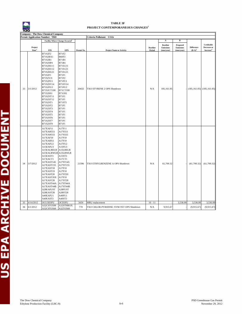
Company: The Dow Chemical CompanyPermit Application Number: TBD Criteria Pollutant: CO2e
A B
ProjectDate2 FIN EPN Permit No. Project Name or Activity
BaselinePeriod
BaselineEmissions(tons/year)
ProposedEmissions(tons/year)
Difference(B-A)5
CreditableDecrease or
Increase6
PROJECT CONTEMPORANEOUS CHANGES1
Facility Where Change Occured3
TABLE 3F
33 3/1/2012
B71S2F2B71S2RX1B71S2B1B71S2SP4B71S2H111B71S2H112B71S2H121B71S2F1B71S2VJ1B71S2FU1B71S2SV14B71S2FU2B71S2CT100B71S20S1B71S2ST11B71S2ST12B71S2ST1B71S2ST2B71S2ST3B71S2ST4B71S2ST5B71S2ST6B71S2ST7B71S2ST9
B71F2B60F3B71B1B71B1B71S123B71S123B71S123B71F1B71F2B71FU1B71SV14B71FU2B71CT100B71OS1B71F1B71F1B71ST1B71F1B71F1B71F1B71F1B71F1B71F1B71F1
20432 TXO STYRENE 2 OPS Shutdown N/A 185,161.05 - (185,161.05) (185,161.05)
34 3/7/2012
A17EAF11A17EAH551A17EAH555A17EAF10A17EARX1A17EAFU2A15EAFU3A15EALRELRA15EALRWLRA15EAST3A17EACT1A17EAST145A17EAST155A17EAST18A17EAST19A17EAST20A17EAST20XA17EAST28A17EAST44AA17EAST44BA28EAFUSTA28EAST28A40EAFU1A40EAST3
A17F11A17S551A17S555A17F10A17F10A17FU2A15FU3A15LRELRA15LRWLRA15ST3A17CT1A17ST145A17ST155A17F10A17F10A17ST20A17F10A17ST28A17ST44AA17ST44BA28FUSTA28ST28A40FU1A40ST3
21596 TXO ETHYLBENZENE A OPS Shutdown N/A 61,700.32 - (61,700.32) (61,700.32)
35 4/14/2012 OCU3D3FU OCD3FU 3434 MRU replacement 10 - 11 - 3,536.00 3,536.00 3,536.00
36 6/1/2012 A32CSTO500A32CSTO560
A32STHROXA32TO560 770 TXO CHLOR-PYRIDINE: SYM-TET OPS Shutdown N/A 9,915.67 - (9,915.67) (9,915.67)
The Dow Chemical CompanyEthylene Production Facility (LHC-9) A-6
PSD Greenhouse Gas PermitNovember 29, 2012
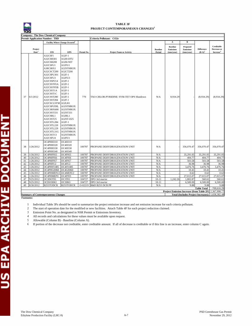
Company: The Dow Chemical CompanyPermit Application Number: TBD Criteria Pollutant: CO2e
A B
ProjectDate2 FIN EPN Permit No. Project Name or Activity
BaselinePeriod
BaselineEmissions(tons/year)
ProposedEmissions(tons/year)
Difference(B-A)5
CreditableDecrease or
Increase6
PROJECT CONTEMPORANEOUS CHANGES1
Facility Where Change Occured3
TABLE 3F
37 6/1/2012
A32CSF1A32CSH301A32CSH200A32CSFU1A38CSRX1A32CSCT200A32CSPU301A32CSFU3A32CSSP214A32CSST05AA32CSST05BA32CSST1AA32CSST1CA32CSST280A32CSST284A32CSCLSYMA32CSPUDILA32CSRX600A32CSST331A32CSRL1A32CSST25A32CSTL284A32CSTL220A32CSTL229A32CSTL31GA32CSST13A32CSFU4
A32F-1A32H-DTUA32H-NITA32FU1A32STHROXA32CT200A32F-1A32FU3A32F-1A32F-1A32F-1A32F-1A32F-1A32F-1A32F-1A32LR1A32STHROXA32STHROXA32ST331A32RL1A32ST-D25A32F-1A32STHROXA32STHROXA32STHROXA32STHROXA32FU1
770 TXO CHLOR-PYRIDINE: SYM-TET OPS Shutdown N/A 8,934.29 - (8,934.29) (8,934.29)
38 1/26/2012
OC4PHH310OC4PHH320OC4PHH330OC4PHH340
OC4H310OC4H320OC4H330OC4H340
100787 PROPANE DEHYDROGENATION UNIT N/A - 356,070.47 356,070.47 356,070.47
39 1/26/2012 OC4PHF955 OC4F955 100787 PROPANE DEHYDROGENATION UNIT N/A - 35,291.05 35,291.05 35,291.0540 1/26/2012 OC4PHF956 OC4F956 100787 PROPANE DEHYDROGENATION UNIT N/A - 404.77 404.77 404.7741 1/26/2012 OC4PHF957 OC4F957 100787 PROPANE DEHYDROGENATION UNIT N/A - 503.58 503.58 503.5842 1/26/2012 OC4PHFU2 OC4FU2 100787 PROPANE DEHYDROGENATION UNIT N/A - 36.98 36.98 36.9843 1/26/2012 OC4PHSV485 OC4SV485 100787 PROPANE DEHYDROGENATION UNIT N/A - 3,476.76 3,476.76 3,476.7644 1/26/2012 OC4PHGE860 OC4GE860 100787 PROPANE DEHYDROGENATION UNIT N/A - 10.41 10.41 10.4145 1/26/2012 OC4PHMEFU2 OC4MEFU2 100787 PROPANE DEHYDROGENATION UNIT N/A - 0.62 0.62 0.6246 1/26/2012 OC4PHMEPU OC4F955 100787 PROPANE DEHYDROGENATION UNIT N/A - 27,015.07 27,015.07 27,015.0747 9/25/2012 OC3DOT01 OC3T01 104727 DPO 3rd reactor 10-11 1,242.26 1,802.87 560.61 560.6148 9/25/2012 OCDO3H63 OC3H63 104727 DPO 3rd reactor 10-11 - 6,500.00 6,500.00 6,500.0049 8/30/2012 B255TODCR B255TODCR O-02219 R&D B255 DCR PP N/A - 9.88 9.88 9.88
Table Total -709,616.29Project Emission Increase (from Table 2F) 2,367,998.77
Summary of Contemporaneous Changes Total (Includes Project Increases): 1,658,382.48Footnotes:
1. Individual Table 3Fs should be used to summarize the project emission increase and net emission increase for each criteria pollutant.2. The start of operation date for the modified or new facilities. Attach Table 4F for each project reduction claimed.3. Emission Point No. as designated in NSR Permit or Emissions Inventory.4. All records and calculations for these values must be available upon request.5. Allowable (Column B) - Baseline (Column A).6. If portion of the decrease not creditable, enter creditable amount. If all of decrease is creditable or if this line is an increase, enter column C again.
The Dow Chemical CompanyEthylene Production Facility (LHC-9) A-7
PSD Greenhouse Gas PermitNovember 29, 2012
Appendix B Emissions Calculations
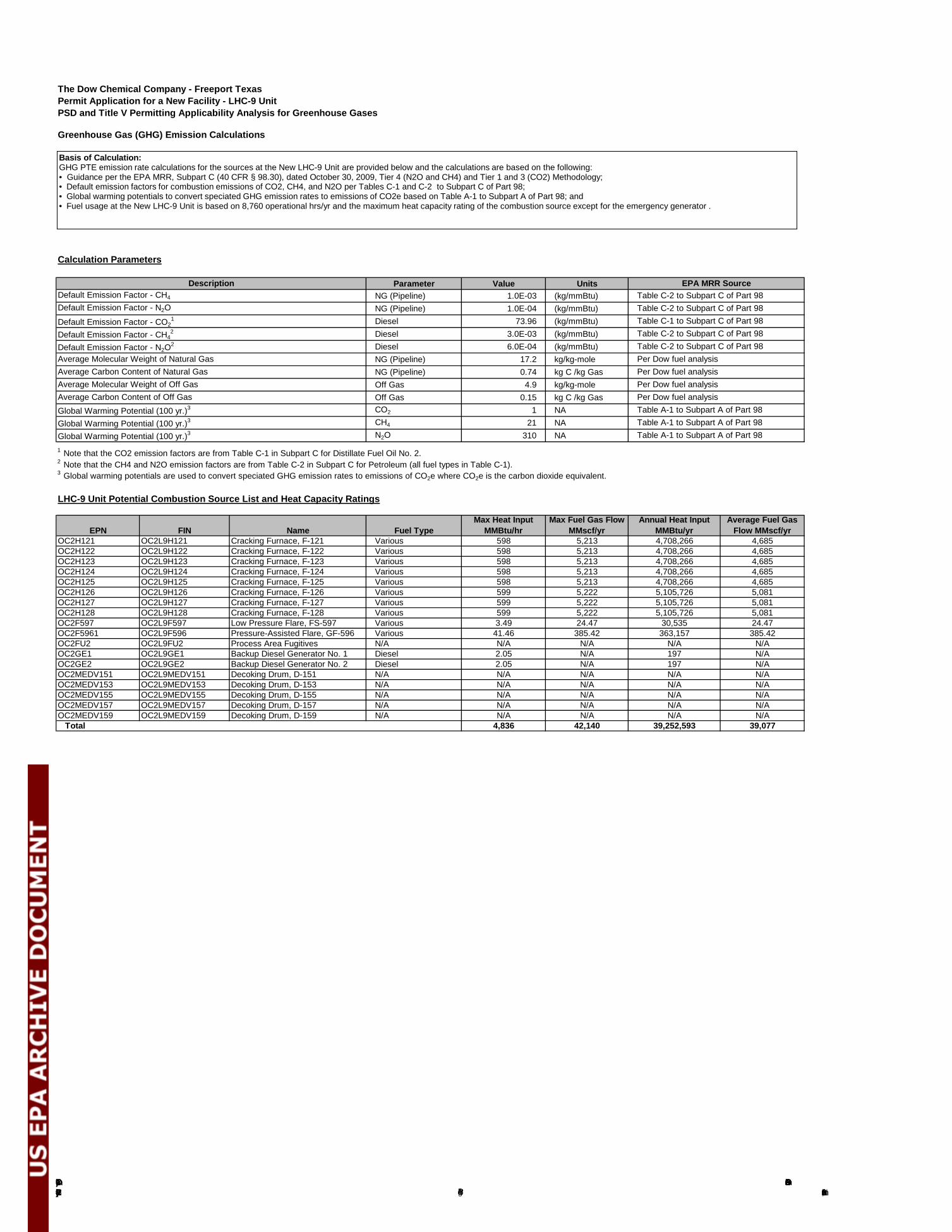
The Dow Chemical Company Ethylene Production Facility (LHC-9)
PSD Greenhouse Gas PermitNovember 28, 2012Page B-1
The Dow Chemical Company - Freeport TexasPermit Application for a New Facility - LHC-9 UnitPSD and Title V Permitting Applicability Analysis for Greenhouse Gases
Greenhouse Gas (GHG) Emission Calculations
Calculation Parameters
Parameter Value UnitsNG (Pipeline) 1.0E-03 (kg/mmBtu)NG (Pipeline) 1.0E-04 (kg/mmBtu)Diesel 73.96 (kg/mmBtu)Diesel 3.0E-03 (kg/mmBtu)Diesel 6.0E-04 (kg/mmBtu)NG (Pipeline) 17.2 kg/kg-moleNG (Pipeline) 0.74 kg C /kg GasOff Gas 4.9 kg/kg-moleOff Gas 0.15 kg C /kg GasCO2 1 NACH4 21 NAN2O 310 NA
1 Note that the CO2 emission factors are from Table C-1 in Subpart C for Distillate Fuel Oil No. 2.2 Note that the CH4 and N2O emission factors are from Table C-2 in Subpart C for Petroleum (all fuel types in Table C-1).3 Global warming potentials are used to convert speciated GHG emission rates to emissions of CO2e where CO2e is the carbon dioxide equivalent.
LHC-9 Unit Potential Combustion Source List and Heat Capacity Ratings
OC2H121 OC2L9H121 Cracking Furnace, F-121 Various 598 5,213 4,708,266 4,685OC2H122 OC2L9H122 Cracking Furnace, F-122 Various 598 5,213 4,708,266 4,685OC2H123 OC2L9H123 Cracking Furnace, F-123 Various 598 5,213 4,708,266 4,685OC2H124 OC2L9H124 Cracking Furnace, F-124 Various 598 5,213 4,708,266 4,685OC2H125 OC2L9H125 Cracking Furnace, F-125 Various 598 5,213 4,708,266 4,685OC2H126 OC2L9H126 Cracking Furnace, F-126 Various 599 5,222 5,105,726 5,081OC2H127 OC2L9H127 Cracking Furnace, F-127 Various 599 5,222 5,105,726 5,081OC2H128 OC2L9H128 Cracking Furnace, F-128 Various 599 5,222 5,105,726 5,081OC2F597 OC2L9F597 Low Pressure Flare, FS-597 Various 3.49 24.47 30,535 24.47OC2F5961 OC2L9F596 Pressure-Assisted Flare, GF-596 Various 41.46 385.42 363,157 385.42OC2FU2 OC2L9FU2 Process Area Fugitives N/A N/A N/A N/A N/AOC2GE1 OC2L9GE1 Backup Diesel Generator No. 1 Diesel 2.05 N/A 197 N/AOC2GE2 OC2L9GE2 Backup Diesel Generator No. 2 Diesel 2.05 N/A 197 N/AOC2MEDV151 OC2L9MEDV151 Decoking Drum, D-151 N/A N/A N/A N/A N/AOC2MEDV153 OC2L9MEDV153 Decoking Drum, D-153 N/A N/A N/A N/A N/AOC2MEDV155 OC2L9MEDV155 Decoking Drum, D-155 N/A N/A N/A N/A N/AOC2MEDV157 OC2L9MEDV157 Decoking Drum, D-157 N/A N/A N/A N/A N/AOC2MEDV159 OC2L9MEDV159 Decoking Drum, D-159 N/A N/A N/A N/A N/A
Total 4,836 42,140 39,252,593 39,077
Global Warming Potential (100 yr.)3 Table A-1 to Subpart A of Part 98
EPN FIN Name Fuel TypeMax Fuel Gas Flow
MMscf/yrAverage Fuel Gas
Flow MMscf/yrAnnual Heat Input
MMBtu/yrMax Heat Input
MMBtu/hr
Default Emission Factor - N2O2 Table C-2 to Subpart C of Part 98
Global Warming Potential (100 yr.)3 Table A-1 to Subpart A of Part 98Global Warming Potential (100 yr.)3 Table A-1 to Subpart A of Part 98
Average Carbon Content of Natural Gas Per Dow fuel analysisAverage Molecular Weight of Natural Gas Per Dow fuel analysis
Average Molecular Weight of Off Gas Per Dow fuel analysisAverage Carbon Content of Off Gas Per Dow fuel analysis
Default Emission Factor - CH42 Table C-2 to Subpart C of Part 98
Default Emission Factor - CO21 Table C-1 to Subpart C of Part 98
Default Emission Factor - N2O Table C-2 to Subpart C of Part 98
EPA MRR SourceDefault Emission Factor - CH4 Table C-2 to Subpart C of Part 98
Description
Basis of Calculation: GHG PTE emission rate calculations for the sources at the New LHC-9 Unit are provided below and the calculations are based on the following: • Guidance per the EPA MRR, Subpart C (40 CFR § 98.30), dated October 30, 2009, Tier 4 (N2O and CH4) and Tier 1 and 3 (CO2) Methodology; • Default emission factors for combustion emissions of CO2, CH4, and N2O per Tables C-1 and C-2 to Subpart C of Part 98; • Global warming potentials to convert speciated GHG emission rates to emissions of CO2e based on Table A-1 to Subpart A of Part 98; and • Fuel usage at the New LHC-9 Unit is based on 8,760 operational hrs/yr and the maximum heat capacity rating of the combustion source except for the emergency generator .
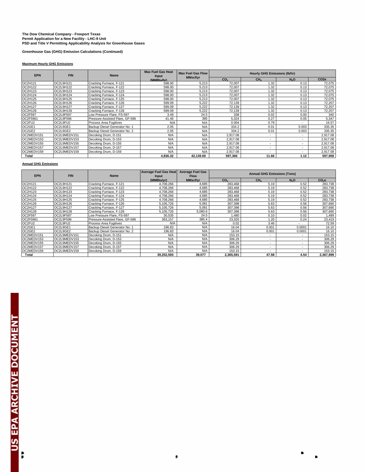
The Dow Chemical Company Ethylene Production Facility (LHC-9)
PSD Greenhouse Gas PermitNovember 28, 2012Page B-2
The Dow Chemical Company - Freeport TexasPermit Application for a New Facility - LHC-9 UnitPSD and Title V Permitting Applicability Analysis for Greenhouse Gases
Greenhouse Gas (GHG) Emission Calculations (Continued)
Maximum Hourly GHG Emissions
CO2 CH4 N2O CO2eOC2H121 OC2L9H121 Cracking Furnace, F-121 598.00 5,213 72,007 1.32 0.13 72,075 OC2H122 OC2L9H122 Cracking Furnace, F-122 598.00 5,213 72,007 1.32 0.13 72,075 OC2H123 OC2L9H123 Cracking Furnace, F-123 598.00 5,213 72,007 1.32 0.13 72,075 OC2H124 OC2L9H124 Cracking Furnace, F-124 598.00 5,213 72,007 1.32 0.13 72,075 OC2H125 OC2L9H125 Cracking Furnace, F-125 598.00 5,213 72,007 1.32 0.13 72,075 OC2H126 OC2L9H126 Cracking Furnace, F-126 599.09 5,222 72,139 1.32 0.13 72,207 OC2H127 OC2L9H127 Cracking Furnace, F-127 599.09 5,222 72,139 1.32 0.13 72,207 OC2H128 OC2L9H128 Cracking Furnace, F-128 599.09 5,222 72,139 1.32 0.13 72,207 OC2F597 OC2L9F597 Low Pressure Flare, FS-597 3.49 24.5 338 0.02 0.00 340 OC2F5961 OC2L9F596 Pressure-Assisted Flare, GF-596 41.46 385 5,324 0.27 0.05 5,347 OC2FU2 OC2L9FU2 Process Area Fugitives N/A N/A 0.004 0.79 - 16.57 OC2GE1 OC2L9GE1 Backup Diesel Generator No. 1 2.05 N/A 334.2 0.01 0.003 335.35 OC2GE2 OC2L9GE2 Backup Diesel Generator No. 2 2.05 N/A 334.2 0.01 0.003 335.35 OC2MEDV151 OC2L9MEDV151 Decoking Drum, D-151 N/A N/A 2,917.08 - - 2,917.08 OC2MEDV153 OC2L9MEDV153 Decoking Drum, D-153 N/A N/A 2,917.08 - - 2,917.08 OC2MEDV155 OC2L9MEDV155 Decoking Drum, D-155 N/A N/A 2,917.08 - - 2,917.08 OC2MEDV157 OC2L9MEDV157 Decoking Drum, D-157 N/A N/A 2,917.08 - - 2,917.08 OC2MEDV159 OC2L9MEDV159 Decoking Drum, D-159 N/A N/A 2,917.08 - - 2,917.08
Total 4,836.32 42,139.69 597,366 11.66 1.12 597,958
Annual GHG Emissions
CO2 CH4 N2O CO2eOC2H121 OC2L9H121 Cracking Furnace, F-121 4,708,266 4,685 283,468 5.19 0.52 283,738 OC2H122 OC2L9H122 Cracking Furnace, F-122 4,708,266 4,685 283,468 5.19 0.52 283,738 OC2H123 OC2L9H123 Cracking Furnace, F-123 4,708,266 4,685 283,468 5.19 0.52 283,738 OC2H124 OC2L9H124 Cracking Furnace, F-124 4,708,266 4,685 283,468 5.19 0.52 283,738 OC2H125 OC2L9H125 Cracking Furnace, F-125 4,708,266 4,685 283,468 5.19 0.52 283,738 OC2H126 OC2L9H126 Cracking Furnace, F-126 5,105,726 5,081 307,398 5.63 0.56 307,690 OC2H127 OC2L9H127 Cracking Furnace, F-127 5,105,726 5,081 307,398 5.63 0.56 307,690 OC2H128 OC2L9H128 Cracking Furnace, F-128 5,105,726 5,080.6 307,398 5.63 0.56 307,690 OC2F597 OC2L9F597 Low Pressure Flare, FS-597 30,535 24.5 1,480 0.10 0.02 1,489 OC2F5961 OC2L9F596 Pressure-Assisted Flare, GF-596 363,157 385.4 23,320 1.20 0.24 23,419 OC2FU2 OC2L9FU2 Process Area Fugitives N/A N/A 0.02 3.46 - 72.59 OC2GE1 OC2L9GE1 Backup Diesel Generator No. 1 196.83 N/A 16.04 0.001 0.0001 16.10 OC2GE2 OC2L9GE2 Backup Diesel Generator No. 2 196.83 N/A 16.04 0.001 0.0001 16.10 OC2MEDV151 OC2L9MEDV151 Decoking Drum, D-151 N/A N/A 153.15 - - 153.15 OC2MEDV153 OC2L9MEDV153 Decoking Drum, D-153 N/A N/A 306.29 - - 306.29 OC2MEDV155 OC2L9MEDV155 Decoking Drum, D-155 N/A N/A 306.29 - - 306.29 OC2MEDV157 OC2L9MEDV157 Decoking Drum, D-157 N/A N/A 306.29 - - 306.29 OC2MEDV159 OC2L9MEDV159 Decoking Drum, D-159 N/A N/A 153.15 - - 153.15
Total 39,252,593 39,077 2,365,591 47.58 4.54 2,367,999
EPN FIN NameAverage Fuel Gas Heat
Input(MMBtu/yr)
Annual GHG Emissions (Tons)Average Fuel Gas Flow
MMscf/yr
EPN FIN NameMax Fuel Gas Heat
Input(MMBtu/hr)
Hourly GHG Emissions (lb/hr)Max Fuel Gas FlowMMscf/yr
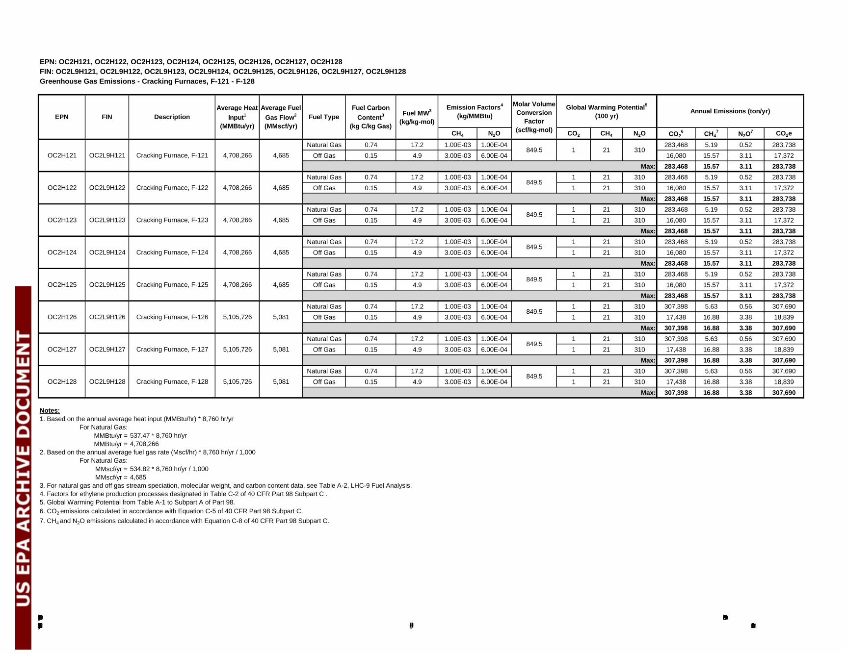
The Dow Chemical Company Ethylene Production Facility (LHC-9)
PSD Greenhouse Gas PermitNovember 28, 2012Page B-3
EPN: OC2H121, OC2H122, OC2H123, OC2H124, OC2H125, OC2H126, OC2H127, OC2H128FIN: OC2L9H121, OC2L9H122, OC2L9H123, OC2L9H124, OC2L9H125, OC2L9H126, OC2L9H127, OC2L9H128Greenhouse Gas Emissions - Cracking Furnaces, F-121 - F-128
CH4 N2O CO2 CH4 N2O CO26 CH4
7 N2O7 CO2e
Natural Gas 0.74 17.2 1.00E-03 1.00E-04 283,468 5.19 0.52 283,738 Off Gas 0.15 4.9 3.00E-03 6.00E-04 16,080 15.57 3.11 17,372
Max: 283,468 15.57 3.11 283,738 Natural Gas 0.74 17.2 1.00E-03 1.00E-04 1 21 310 283,468 5.19 0.52 283,738
Off Gas 0.15 4.9 3.00E-03 6.00E-04 1 21 310 16,080 15.57 3.11 17,372 Max: 283,468 15.57 3.11 283,738
Natural Gas 0.74 17.2 1.00E-03 1.00E-04 1 21 310 283,468 5.19 0.52 283,738 Off Gas 0.15 4.9 3.00E-03 6.00E-04 1 21 310 16,080 15.57 3.11 17,372
Max: 283,468 15.57 3.11 283,738 Natural Gas 0.74 17.2 1.00E-03 1.00E-04 1 21 310 307,398 5.63 0.56 307,690
Off Gas 0.15 4.9 3.00E-03 6.00E-04 1 21 310 17,438 16.88 3.38 18,839 Max: 307,398 16.88 3.38 307,690
Natural Gas 0.74 17.2 1.00E-03 1.00E-04 1 21 310 307,398 5.63 0.56 307,690 Off Gas 0.15 4.9 3.00E-03 6.00E-04 1 21 310 17,438 16.88 3.38 18,839
Max: 307,398 16.88 3.38 307,690 Natural Gas 0.74 17.2 1.00E-03 1.00E-04 1 21 310 307,398 5.63 0.56 307,690
Off Gas 0.15 4.9 3.00E-03 6.00E-04 1 21 310 17,438 16.88 3.38 18,839 Max: 307,398 16.88 3.38 307,690
Notes:1. Based on the annual average heat input (MMBtu/hr) * 8,760 hr/yr
For Natural Gas:MMBtu/yr = 537.47 * 8,760 hr/yrMMBtu/yr = 4,708,266
2. Based on the annual average fuel gas rate (Mscf/hr) * 8,760 hr/yr / 1,000For Natural Gas:
MMscf/yr = 534.82 * 8,760 hr/yr / 1,000MMscf/yr = 4,685
3. For natural gas and off gas stream speciation, molecular weight, and carbon content data, see Table A-2, LHC-9 Fuel Analysis.4. Factors for ethylene production processes designated in Table C-2 of 40 CFR Part 98 Subpart C .5. Global Warming Potential from Table A-1 to Subpart A of Part 98.6. CO2 emissions calculated in accordance with Equation C-5 of 40 CFR Part 98 Subpart C. 7. CH4 and N2O emissions calculated in accordance with Equation C-8 of 40 CFR Part 98 Subpart C.
Fuel TypeFuel Carbon
Content3
(kg C/kg Gas)EPN FIN Description
Average Heat Input1
(MMBtu/yr)
Average Fuel Gas Flow2
(MMscf/yr)
Fuel MW3
(kg/kg-mol)
Molar Volume Conversion
Factor (scf/kg-mol)
849.5
Global Warming Potential5
(100 yr)Annual Emissions (ton/yr)Emission Factors4
(kg/MMBtu)
4,685
849.5
1 21 310
849.5
849.5
849.5
849.5
849.5
849.5
4,685OC2H121
OC2H122 OC2L9H122 Cracking Furnace, F-122 4,708,266
4,708,266Cracking Furnace, F-121OC2L9H121
OC2H124 OC2L9H124 Cracking Furnace, F-124 4,708,266 4,685
OC2H123 OC2L9H123 Cracking Furnace, F-123 4,708,266 4,685
OC2H126 OC2L9H126 Cracking Furnace, F-126 5,105,726 5,081
OC2H125 OC2L9H125 Cracking Furnace, F-125 4,708,266 4,685
OC2H128 OC2L9H128 Cracking Furnace, F-128 5,105,726 5,081
OC2H127 OC2L9H127 Cracking Furnace, F-127 5,105,726 5,081
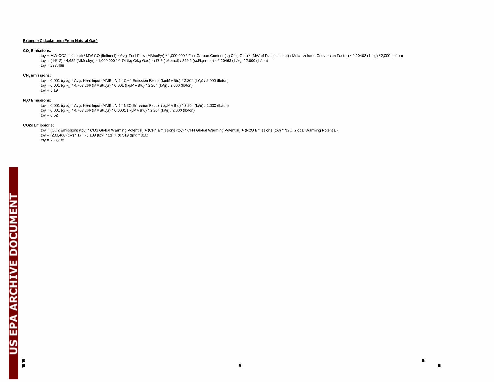
The Dow Chemical Company Ethylene Production Facility (LHC-9)
PSD Greenhouse Gas PermitNovember 28, 2012Page B-4
Example Calculations (From Natural Gas)
CO2 Emissions:tpy = MW CO2 (lb/lbmol) / MW CO (lb/lbmol) * Avg. Fuel Flow (MMscf/yr) * 1,000,000 * Fuel Carbon Content (kg C/kg Gas) * (MW of Fuel (lb/lbmol) / Molar Volume Conversion Factor) * 2.20462 (lb/kg) / 2,000 (lb/ton)tpy = (44/12) * 4,685 (MMscf/yr) * 1,000,000 * 0.74 (kg C/kg Gas) * (17.2 (lb/lbmol) / 849.5 (scf/kg-mol)) * 2.20463 (lb/kg) / 2,000 (lb/ton)tpy = 283,468
CH4 Emissions:tpy = 0.001 (g/kg) * Avg. Heat Input (MMBtu/yr) * CH4 Emission Factor (kg/MMBtu) * 2,204 (lb/g) / 2,000 (lb/ton)tpy = 0.001 (g/kg) * 4,708,266 (MMBtu/yr) * 0.001 (kg/MMBtu) * 2,204 (lb/g) / 2,000 (lb/ton)tpy = 5.19
N2O Emissions:tpy = 0.001 (g/kg) * Avg. Heat Input (MMBtu/yr) * N2O Emission Factor (kg/MMBtu) * 2,204 (lb/g) / 2,000 (lb/ton)tpy = 0.001 (g/kg) * 4,708,266 (MMBtu/yr) * 0.0001 (kg/MMBtu) * 2,204 (lb/g) / 2,000 (lb/ton)tpy = 0.52
CO2e Emissions:tpy = (CO2 Emissions (tpy) * CO2 Global Warming Potential) + (CH4 Emissions (tpy) * CH4 Global Warming Potential) + (N2O Emissions (tpy) * N2O Global Warming Potential)tpy = (283,468 (tpy) * 1) + (5.189 (tpy) * 21) + (0.519 (tpy) * 310)tpy = 283,738
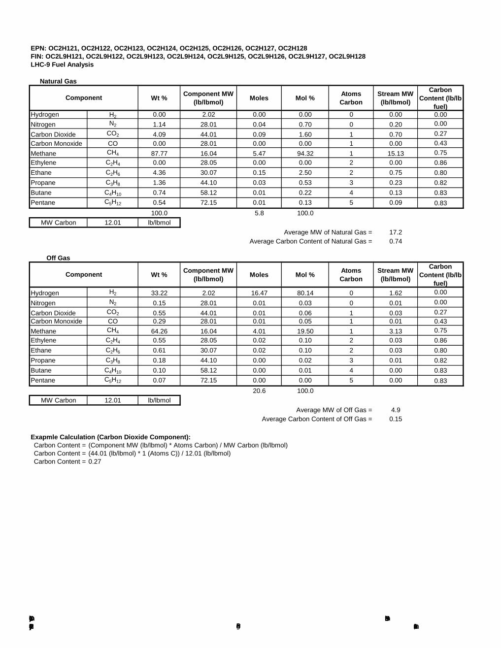
The Dow Chemical Company Ethylene Production Facility (LHC-9)
PSD Greenhouse Gas PermitNovember 28, 2012Page B-5
EPN: OC2H121, OC2H122, OC2H123, OC2H124, OC2H125, OC2H126, OC2H127, OC2H128FIN: OC2L9H121, OC2L9H122, OC2L9H123, OC2L9H124, OC2L9H125, OC2L9H126, OC2L9H127, OC2L9H128
Natural Gas
Wt % Component MW (lb/lbmol) Moles Mol % Atoms
CarbonStream MW (lb/lbmol)
Carbon Content (lb/lb
fuel)Hydrogen H2 0.00 2.02 0.00 0.00 0 0.00 0.00Nitrogen N2 1.14 28.01 0.04 0.70 0 0.20 0.00Carbon Dioxide CO2 4.09 44.01 0.09 1.60 1 0.70 0.27Carbon Monoxide CO 0.00 28.01 0.00 0.00 1 0.00 0.43Methane CH4 87.77 16.04 5.47 94.32 1 15.13 0.75Ethylene C2H4 0.00 28.05 0.00 0.00 2 0.00 0.86Ethane C2H6 4.36 30.07 0.15 2.50 2 0.75 0.80Propane C3H8 1.36 44.10 0.03 0.53 3 0.23 0.82Butane C4H10 0.74 58.12 0.01 0.22 4 0.13 0.83Pentane C5H12 0.54 72.15 0.01 0.13 5 0.09 0.83
100.0 5.8 100.0MW Carbon 12.01 lb/lbmol
Average MW of Natural Gas = 17.2Average Carbon Content of Natural Gas = 0.74
Off Gas
Wt % Component MW (lb/lbmol) Moles Mol % Atoms
CarbonStream MW (lb/lbmol)
Carbon Content (lb/lb
fuel)Hydrogen H2 33.22 2.02 16.47 80.14 0 1.62 0.00Nitrogen N2 0.15 28.01 0.01 0.03 0 0.01 0.00Carbon Dioxide CO2 0.55 44.01 0.01 0.06 1 0.03 0.27Carbon Monoxide CO 0.29 28.01 0.01 0.05 1 0.01 0.43Methane CH4 64.26 16.04 4.01 19.50 1 3.13 0.75Ethylene C2H4 0.55 28.05 0.02 0.10 2 0.03 0.86Ethane C2H6 0.61 30.07 0.02 0.10 2 0.03 0.80Propane C3H8 0.18 44.10 0.00 0.02 3 0.01 0.82Butane C4H10 0.10 58.12 0.00 0.01 4 0.00 0.83Pentane C5H12 0.07 72.15 0.00 0.00 5 0.00 0.83
20.6 100.0MW Carbon 12.01 lb/lbmol
Average MW of Off Gas = 4.9Average Carbon Content of Off Gas = 0.15
Exapmle Calculation (Carbon Dioxide Component):Carbon Content = (Component MW (lb/lbmol) * Atoms Carbon) / MW Carbon (lb/lbmol)Carbon Content = (44.01 (lb/lbmol) * 1 (Atoms C)) / 12.01 (lb/lbmol)Carbon Content = 0.27
Component
LHC-9 Fuel Analysis
Component

The Dow Chemical Company Ethylene Production Facility (LHC-9)
PSD Greenhouse Gas PermitNovember 28, 2012Page B-6
EPN: OC2F597FIN: OC2L9F597Greenhouse Gas Emissions - Low Pressure Flare, FS-597
CH4 N2O CO2 CH4 N2O CO26 CH4
7 N2O7 CO2e
Natural Gas 0.74 17.2 1.00E-03 1.00E-04 1,480 0.03 0.00 1,482 Off Gas 0.15 4.9 3.00E-03 6.00E-04 84 0.10 0.02 92
Max: 1,480 0.10 0.02 1,489
Notes:1. Based on the annual average heat input (MMBtu/hr) * 8,760 hr/yr
For Natural Gas:MMBtu/yr = 3.49 * 8,760 hr/yrMMBtu/yr = 30,535
2. Based on the annual average fuel gas rate (scfm) * 60 * 8,760 hr/yr / 1,000,000For Natural Gas:
MMscf/yr = 46.55 scfm * 60 min/hr * 8,760 hr/yr / 1,000,000 MMscf/yr = 24.47
3. For natural gas and off gas stream speciation, molecular weight, and carbon content data, see Table A-2, LHC-9 Fuel Analysis.4. Factors for ethylene production processes designated in Table C-2 of 40 CFR Part 98 Subpart C .5. Global Warming Potential from Table A-1 to Subpart A of Part 98.6. CO2 emissions calculated in accordance with Equation C-5 of 40 CFR Part 98 Subpart C. 7. CH4 and N2O emissions calculated in accordance with Equation C-8 of 40 CFR Part 98 Subpart C.
Example Calculations (From Natural Gas)
CO2 Emissions:tpy = MW CO2 (lb/lbmol) / MW CO (lb/lbmol) * Avg. Fuel Flow (MMscf/yr) * 1,000,000 * Fuel Carbon Content (kg C/kg Gas) * (MW of Fuel (lb/lbmol) / Molar Volume Conversion Factor) * 2.20462 (lb/kg) / 2,000 (lb/ton)tpy = (44/12) * 24.47 (MMscf/yr) * 1,000,000 * 0.74 (kg C/kg Gas) * (17.2 (lb/lbmol) / 849.5 (scf/kg-mol)) * 2.20463 (lb/kg) / 2,000 (lb/ton)tpy = 1,480
CH4 Emissions:tpy = 0.001 (g/kg) * Avg. Heat Input (MMBtu/yr) * CH4 Emission Factor (kg/MMBtu) * 2,204 (lb/g) / 2,000 (lb/ton)tpy = 0.001 (g/kg) * 30,535 (MMBtu/yr) * 0.001 (kg/MMBtu) * 2,204 (lb/g) / 2,000 (lb/ton)tpy = 0.03
N2O Emissions:tpy = 0.001 (g/kg) * Avg. Heat Input (MMBtu/yr) * N2O Emission Factor (kg/MMBtu) * 2,204 (lb/g) / 2,000 (lb/ton)tpy = 0.001 (g/kg) * 30,535 (MMBtu/yr) * 0.0001 (kg/MMBtu) * 2,204 (lb/g) / 2,000 (lb/ton)tpy = 0.00
CO2e Emissions:tpy = (CO2 Emissions (tpy) * CO2 Global Warming Potential) + (CH4 Emissions (tpy) * CH4 Global Warming Potential) + (N2O Emissions (tpy) * N2O Global Warming Potential)tpy = (1,480 (tpy) * 1) + (0.034 (tpy) * 21) + (0.003 (tpy) * 310)tpy = 1,482
Annual Emissions (ton/yr)EPN FIN Description
Average Heat Input1
(MMBtu/yr)
Average Fuel Gas
Flow2
(MMscf/yr)
Fuel TypeFuel Carbon
Content3
(kg C/kg Gas)
Fuel MW3
(kg/kg-mol)
Molar Volume Conversion
Factor (scf/kg-mol)
Emission Factors4
(kg/MMBtu)Global Warming Potential5
(100 yr)
310211OC2F597 OC2L9F597 Low Pressure Flare, FS-597 30,535 24.47
849.5
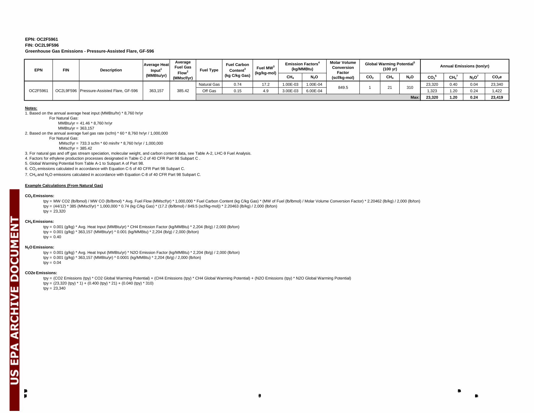
The Dow Chemical Company Ethylene Production Facility (LHC-9)
PSD Greenhouse Gas PermitNovember 28, 2012Page B-7
EPN: OC2F5961FIN: OC2L9F596Greenhouse Gas Emissions - Pressure-Assisted Flare, GF-596
CH4 N2O CO2 CH4 N2O CO26 CH4
7 N2O7 CO2e
Natural Gas 0.74 17.2 1.00E-03 1.00E-04 23,320 0.40 0.04 23,340 Off Gas 0.15 4.9 3.00E-03 6.00E-04 1,323 1.20 0.24 1,422
Max: 23,320 1.20 0.24 23,419
Notes:1. Based on the annual average heat input (MMBtu/hr) * 8,760 hr/yr
For Natural Gas:MMBtu/yr = 41.46 * 8,760 hr/yrMMBtu/yr = 363,157
2. Based on the annual average fuel gas rate (scfm) * 60 * 8,760 hr/yr / 1,000,000For Natural Gas:
MMscf/yr = 733.3 scfm * 60 min/hr * 8,760 hr/yr / 1,000,000 MMscf/yr = 385.42
3. For natural gas and off gas stream speciation, molecular weight, and carbon content data, see Table A-2, LHC-9 Fuel Analysis.4. Factors for ethylene production processes designated in Table C-2 of 40 CFR Part 98 Subpart C .5. Global Warming Potential from Table A-1 to Subpart A of Part 98.6. CO2 emissions calculated in accordance with Equation C-5 of 40 CFR Part 98 Subpart C. 7. CH4 and N2O emissions calculated in accordance with Equation C-8 of 40 CFR Part 98 Subpart C.
Example Calculations (From Natural Gas)
CO2 Emissions:tpy = MW CO2 (lb/lbmol) / MW CO (lb/lbmol) * Avg. Fuel Flow (MMscf/yr) * 1,000,000 * Fuel Carbon Content (kg C/kg Gas) * (MW of Fuel (lb/lbmol) / Molar Volume Conversion Factor) * 2.20462 (lb/kg) / 2,000 (lb/ton)tpy = (44/12) * 385 (MMscf/yr) * 1,000,000 * 0.74 (kg C/kg Gas) * (17.2 (lb/lbmol) / 849.5 (scf/kg-mol)) * 2.20463 (lb/kg) / 2,000 (lb/ton)tpy = 23,320
CH4 Emissions:tpy = 0.001 (g/kg) * Avg. Heat Input (MMBtu/yr) * CH4 Emission Factor (kg/MMBtu) * 2,204 (lb/g) / 2,000 (lb/ton)tpy = 0.001 (g/kg) * 363,157 (MMBtu/yr) * 0.001 (kg/MMBtu) * 2,204 (lb/g) / 2,000 (lb/ton)tpy = 0.40
N2O Emissions:tpy = 0.001 (g/kg) * Avg. Heat Input (MMBtu/yr) * N2O Emission Factor (kg/MMBtu) * 2,204 (lb/g) / 2,000 (lb/ton)tpy = 0.001 (g/kg) * 363,157 (MMBtu/yr) * 0.0001 (kg/MMBtu) * 2,204 (lb/g) / 2,000 (lb/ton)tpy = 0.04
CO2e Emissions:tpy = (CO2 Emissions (tpy) * CO2 Global Warming Potential) + (CH4 Emissions (tpy) * CH4 Global Warming Potential) + (N2O Emissions (tpy) * N2O Global Warming Potential)tpy = (23,320 (tpy) * 1) + (0.400 (tpy) * 21) + (0.040 (tpy) * 310)tpy = 23,340
Annual Emissions (ton/yr)EPN FIN Description
Average Heat Input1
(MMBtu/yr)
Average Fuel Gas
Flow2
(MMscf/yr)
Fuel TypeFuel Carbon
Content3
(kg C/kg Gas)
Fuel MW3
(kg/kg-mol)
Emission Factors4
(kg/MMBtu)Molar Volume Conversion
Factor (scf/kg-mol)
Global Warming Potential5
(100 yr)
1 21 310OC2F5961 OC2L9F596 Pressure-Assisted Flare, GF-596 363,157 385.42
849.5
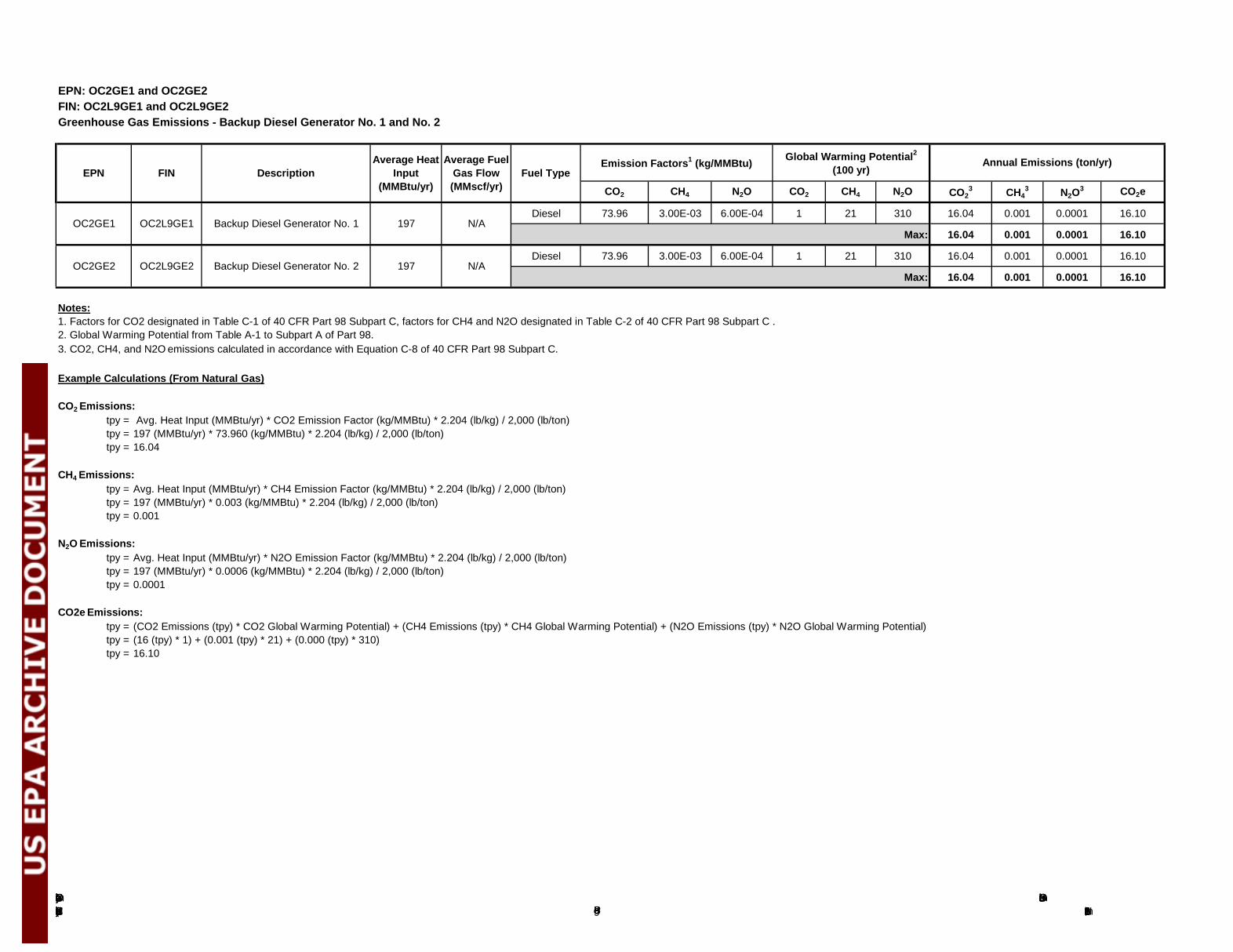
The Dow Chemical Company Ethylene Production Facility (LHC-9)
PSD Greenhouse Gas PermitNovember 28, 2012Page B-8
EPN: OC2GE1 and OC2GE2FIN: OC2L9GE1 and OC2L9GE2Greenhouse Gas Emissions - Backup Diesel Generator No. 1 and No. 2
CO2 CH4 N2O CO2 CH4 N2O CO23 CH4
3 N2O3 CO2e
Diesel 73.96 3.00E-03 6.00E-04 1 21 310 16.04 0.001 0.0001 16.10
Max: 16.04 0.001 0.0001 16.10
Diesel 73.96 3.00E-03 6.00E-04 1 21 310 16.04 0.001 0.0001 16.10
Max: 16.04 0.001 0.0001 16.10
Notes:1. Factors for CO2 designated in Table C-1 of 40 CFR Part 98 Subpart C, factors for CH4 and N2O designated in Table C-2 of 40 CFR Part 98 Subpart C .2. Global Warming Potential from Table A-1 to Subpart A of Part 98.3. CO2, CH4, and N2O emissions calculated in accordance with Equation C-8 of 40 CFR Part 98 Subpart C.
Example Calculations (From Natural Gas)
CO2 Emissions:tpy = Avg. Heat Input (MMBtu/yr) * CO2 Emission Factor (kg/MMBtu) * 2.204 (lb/kg) / 2,000 (lb/ton)tpy = 197 (MMBtu/yr) * 73.960 (kg/MMBtu) * 2.204 (lb/kg) / 2,000 (lb/ton)tpy = 16.04
CH4 Emissions:tpy = Avg. Heat Input (MMBtu/yr) * CH4 Emission Factor (kg/MMBtu) * 2.204 (lb/kg) / 2,000 (lb/ton)tpy = 197 (MMBtu/yr) * 0.003 (kg/MMBtu) * 2.204 (lb/kg) / 2,000 (lb/ton)tpy = 0.001
N2O Emissions:tpy = Avg. Heat Input (MMBtu/yr) * N2O Emission Factor (kg/MMBtu) * 2.204 (lb/kg) / 2,000 (lb/ton)tpy = 197 (MMBtu/yr) * 0.0006 (kg/MMBtu) * 2.204 (lb/kg) / 2,000 (lb/ton)tpy = 0.0001
CO2e Emissions:tpy = (CO2 Emissions (tpy) * CO2 Global Warming Potential) + (CH4 Emissions (tpy) * CH4 Global Warming Potential) + (N2O Emissions (tpy) * N2O Global Warming Potential)tpy = (16 (tpy) * 1) + (0.001 (tpy) * 21) + (0.000 (tpy) * 310)tpy = 16.10
N/A
Emission Factors1 (kg/MMBtu)
N/AOC2GE1 OC2L9GE1 Backup Diesel Generator No. 1 197
OC2GE2 OC2L9GE2 Backup Diesel Generator No. 2 197
Global Warming Potential2
(100 yr)Annual Emissions (ton/yr)
EPN FIN DescriptionAverage Heat
Input (MMBtu/yr)
Average Fuel Gas Flow (MMscf/yr)
Fuel Type
Appendix C TCEQ LDAR Sample Special Conditions: 28 VHP
The Dow Chemical Company Page C-1 PSD Greenhouse Gas Permit Ethylene Production Facility (LHC-9) November 28, 2012
Texas Commission on Environmental Quality Air Permits Division
New Source Review (NSR) Boilerplate Special Conditions
This information is maintained by the Chemical NSR Section and is subject to change. Last update was made August 2011. These special conditions represent current NSR boilerplate guidelines and are provided for informational purposes only. The special conditions for any permit or amendment are subject to change through TCEQ case-by-case evaluation procedures [30 TAC 116.111(a)]. Please contact the appropriate Chemical NSR Section management if there are questions related to the boilerplate guidelines. Piping, Valves, Connectors, Pumps, and Compressors in Volatile Organic Compounds (VOC) Service - 28VHP Except as may be provided for in the special conditions of this permit, the following requirements apply to the above-referenced equipment: A. These conditions shall not apply (1) where the VOC has an aggregate partial pressure or
vapor pressure of less than 0.044 pounds per square inch, absolute (psia) at 68 degrees Fahrenheit or (2) operating pressure is at least 5 kilopascals (0.725 psi) below ambient pressure. Equipment excluded from this condition shall be identified in a list or by one of the methods described below to be made available upon request.
The exempted components may be identified by one or more of the following methods:
i. piping and instrumentation diagram (PID); or ii. a written or electronic database.
B. Construction of new and reworked piping, valves, pump systems, and compressor
systems shall conform to applicable American National Standards Institute (ANSI), American Petroleum Institute (API), American Society of Mechanical Engineers (ASME), or equivalent codes.
C. New and reworked underground process pipelines shall contain no buried valves such
that fugitive emission monitoring is rendered impractical. D. To the extent that good engineering practice will permit, new and reworked valves and
piping connections shall be so located to be reasonably accessible for leak-checking during plant operation. Non-accessible valves, as defined by Title 30 Texas Administrative Code Chapter 115 (30 TAC Chapter 115), shall be identified in a list to be made available upon request. The non-accessible valves may be identified by one or more of the methods described in subparagraph A above.
The Dow Chemical Company Page C-2 PSD Greenhouse Gas Permit Ethylene Production Facility (LHC-9) November 28, 2012
E. New and reworked piping connections shall be welded or flanged. Screwed connections are permissible only on piping smaller than two-inch diameter. Gas or hydraulic testing of the new and reworked piping connections at no less than operating pressure shall be performed prior to returning the components to service or they shall be monitored for leaks using an approved gas analyzer within 8 hours of the components being returned to service. Adjustments shall be made as necessary to obtain leak-free performance. Connectors shall be inspected by visual, audible, and/or olfactory means at least weekly by operating personnel walk-through.
Each open-ended valve or line shall be equipped with a cap, blind flange, plug, or a second valve. Except during sampling, the second valve shall be closed. If the removal of a component for repair or replacement results in an open-ended line or valve, it is exempt from the requirement to install a cap, blind flange, plug, or second valve for 24 hours. If the repair or replacement is not completed within 24 hours, the line or valve must have a cap, blind flange, plug, or second valve installed.
F. Accessible valves shall be monitored by leak-checking for fugitive emissions at least
quarterly using an approved gas analyzer. Sealless/leakless valves (including, but not limited to, welded bonnet bellows and diaphragm valves) and relief valves equipped with a rupture disc upstream or venting to a control device are not required to be monitored. For valves equipped with rupture discs, a pressure-sensing device shall be installed between the relief valve and rupture disc to monitor disc integrity. All leaking discs shall be replaced at the earliest opportunity but no later than the next process shutdown.
An approved gas analyzer shall conform to requirements listed in Method 21 of 40 CFR part 60, appendix A. The gas analyzer shall be calibrated with methane. In addition, the response factor of the instrument for a specific VOC of interest shall be determined and meet the requirements of Section 8 of Method 21. If a mixture of VOCs are being monitored, the response factor shall be calculated for the average composition of the process fluid. If a response factor less than 10 cannot be achieved using methane, than the instrument may be calibrated with one of the VOC to be measured or any other VOC so long as the instrument has a response factor of less than 10 for each of the VOC to be measured. Replacements for leaking components shall be re-monitored within 15 days of being placed back into VOC service.
G. Except as may be provided for in the special conditions of this permit, all pump,
compressor, and agitator seals shall be monitored with an approved gas analyzer at least quarterly or be equipped with a shaft sealing system that prevents or detects emissions of VOC from the seal. Seal systems designed and operated to prevent emissions or seals equipped with an automatic seal failure detection and alarm system need not be monitored. These seal systems may include (but are not limited to) dual pump seals with barrier fluid at higher pressure than process pressure, seals degassing to vent control systems kept in good working order, or seals equipped with an automatic seal failure
The Dow Chemical Company Page C-3 PSD Greenhouse Gas Permit Ethylene Production Facility (LHC-9) November 28, 2012
detection and alarm system. Submerged pumps or sealless pumps (including, but not limited to, diaphragm, canned, or magnetic-driven pumps) may be used to satisfy the requirements of this condition and need not be monitored.
H. Damaged or leaking valves or connectors found to be emitting VOC in excess of
500 parts per million by volume (ppmv) or found by visual inspection to be leaking (e.g., dripping process fluids) shall be tagged and replaced or repaired. Damaged or leaking pump, compressor, and agitator seals found to be emitting VOC in excess of 2,000 ppmv or found by visual inspection to be leaking (e.g., dripping process fluids) shall be tagged and replaced or repaired.
I. Every reasonable effort shall be made to repair a leaking component, as specified in this
paragraph, within 15 days after the leak is found. If the repair of a component would require a unit shutdown that would create more emissions than the repair would eliminate, the repair may be delayed until the next scheduled shutdown. All leaking components which cannot be repaired until a scheduled shutdown shall be identified for such repair by tagging. A listing of all components that qualify for delay of repair shall be maintained on a delay of repair list. The cumulative daily emissions from all components on the delay of repair list shall be estimated by multiplying by 24 the mass emission rate for each component calculated in accordance with the instructions in 30 TAC 115.782 (c)(1)(B)(i)(II). When the cumulative daily emission rate of all components on the delay of repair list times the number of days until the next scheduled unit shutdown is equal to or exceeds the total emissions from a unit shutdown, the TCEQ Executive Director or designated representative shall be notified and may require early unit shutdown or other appropriate action based on the number and severity of tagged leaks awaiting shutdown.
J. The results of the required fugitive instrument monitoring and maintenance program shall
be made available to the TCEQ Executive Director or designated representative upon request. Records shall indicate appropriate dates, test methods, instrument readings, repair results, justification for delay of repairs, and corrective actions taken for all components. Records of physical inspections shall be noted in the operator’s log or equivalent.
K. Alternative monitoring frequency schedules of 30 TAC §§ 115.352 - 115.359 or National
Emission Standards for Organic Hazardous Air Pollutants, 40 CFR Part 63, Subpart H, may be used in lieu of Items F through G of this condition.
L. Compliance with the requirements of this condition does not assure compliance with
requirements of 30 TAC Chapter 115, an applicable New Source Performance Standard (NSPS), or an applicable National Emission Standard for Hazardous Air Pollutants (NESHAPS) and does not constitute approval of alternative standards for these regulations.
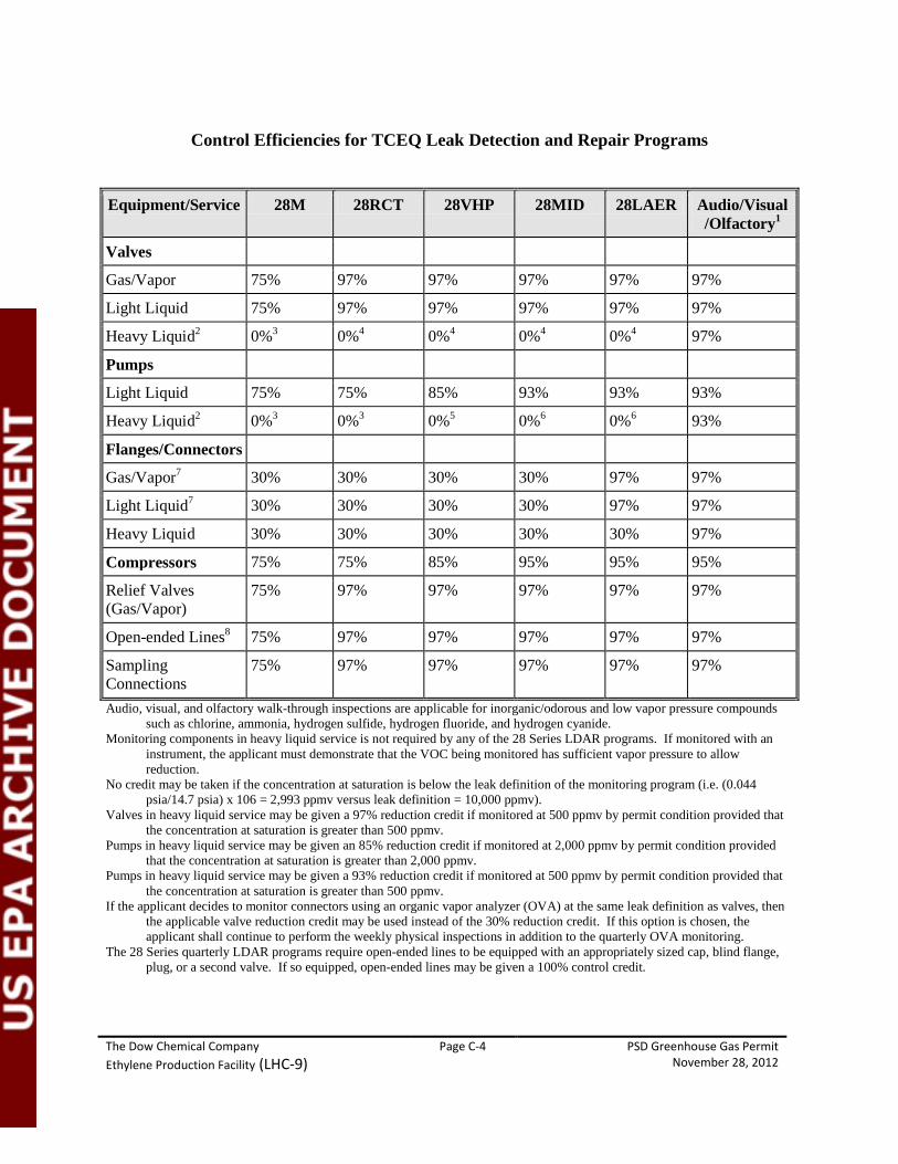
The Dow Chemical Company Page C-4 PSD Greenhouse Gas Permit Ethylene Production Facility (LHC-9) November 28, 2012
Control Efficiencies for TCEQ Leak Detection and Repair Programs
Equipment/Service 28M 28RCT 28VHP 28MID 28LAER Audio/Visual
/Olfactory1
Valves
Gas/Vapor 75% 97% 97% 97% 97% 97%
Light Liquid 75% 97% 97% 97% 97% 97%
Heavy Liquid2 0%3 0%4 0%4 0%4 0%4 97%
Pumps
Light Liquid 75% 75% 85% 93% 93% 93%
Heavy Liquid2 0%3 0%3 0%5 0%6 0%6 93%
Flanges/Connectors
Gas/Vapor7 30% 30% 30% 30% 97% 97%
Light Liquid7 30% 30% 30% 30% 97% 97%
Heavy Liquid 30% 30% 30% 30% 30% 97%
Compressors 75% 75% 85% 95% 95% 95%
Relief Valves (Gas/Vapor)
75% 97% 97% 97% 97% 97%
Open-ended Lines8 75% 97% 97% 97% 97% 97%
Sampling Connections
75% 97% 97% 97% 97% 97%
Audio, visual, and olfactory walk-through inspections are applicable for inorganic/odorous and low vapor pressure compounds such as chlorine, ammonia, hydrogen sulfide, hydrogen fluoride, and hydrogen cyanide.
Monitoring components in heavy liquid service is not required by any of the 28 Series LDAR programs. If monitored with an instrument, the applicant must demonstrate that the VOC being monitored has sufficient vapor pressure to allow reduction.
No credit may be taken if the concentration at saturation is below the leak definition of the monitoring program (i.e. (0.044 psia/14.7 psia) x 106 = 2,993 ppmv versus leak definition = 10,000 ppmv).
Valves in heavy liquid service may be given a 97% reduction credit if monitored at 500 ppmv by permit condition provided that the concentration at saturation is greater than 500 ppmv.
Pumps in heavy liquid service may be given an 85% reduction credit if monitored at 2,000 ppmv by permit condition provided that the concentration at saturation is greater than 2,000 ppmv.
Pumps in heavy liquid service may be given a 93% reduction credit if monitored at 500 ppmv by permit condition provided that the concentration at saturation is greater than 500 ppmv.
If the applicant decides to monitor connectors using an organic vapor analyzer (OVA) at the same leak definition as valves, then the applicable valve reduction credit may be used instead of the 30% reduction credit. If this option is chosen, the applicant shall continue to perform the weekly physical inspections in addition to the quarterly OVA monitoring.
The 28 Series quarterly LDAR programs require open-ended lines to be equipped with an appropriately sized cap, blind flange, plug, or a second valve. If so equipped, open-ended lines may be given a 100% control credit.
Appendix D RACT/BACT/LAER Clearinghouse Search Results
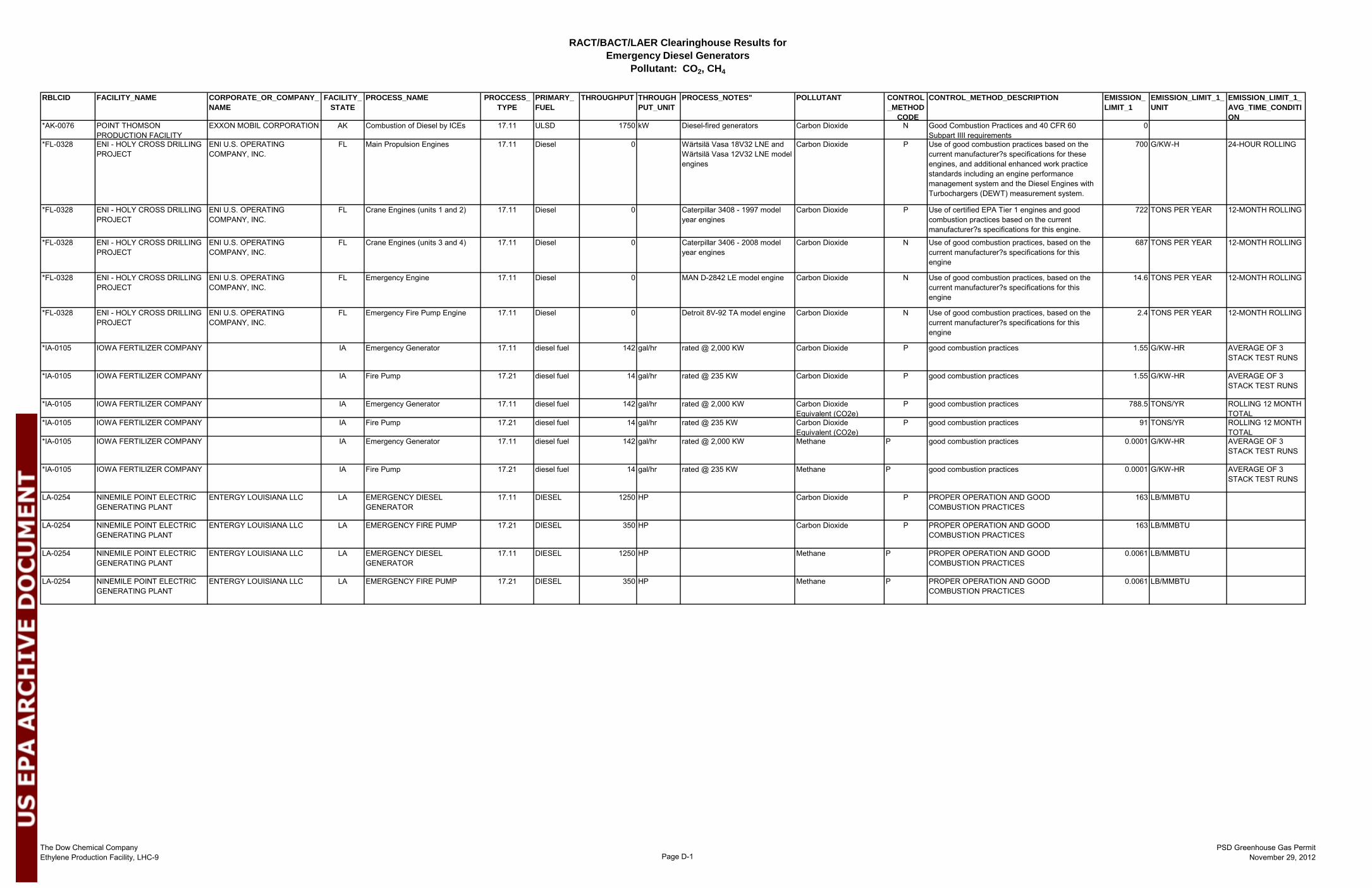
RACT/BACT/LAER Clearinghouse Results for Emergency Diesel Generators
Pollutant: CO2, CH4
The Dow Chemical CompanyEthylene Production Facility, LHC-9 Page D-1
PSD Greenhouse Gas PermitNovember 29, 2012
RBLCID FACILITY_NAME CORPORATE_OR_COMPANY_NAME
FACILITY_STATE
PROCESS_NAME PROCCESS_TYPE
PRIMARY_FUEL
THROUGHPUT THROUGHPUT_UNIT
PROCESS_NOTES" POLLUTANT CONTROL_METHOD
CODE
CONTROL_METHOD_DESCRIPTION EMISSION_LIMIT_1
EMISSION_LIMIT_1_UNIT
EMISSION_LIMIT_1_AVG_TIME_CONDITION
*AK-0076 POINT THOMSON PRODUCTION FACILITY
EXXON MOBIL CORPORATION AK Combustion of Diesel by ICEs 17.11 ULSD 1750 kW Diesel-fired generators Carbon Dioxide N Good Combustion Practices and 40 CFR 60 Subpart IIII requirements
0
*FL-0328 ENI - HOLY CROSS DRILLING PROJECT
ENI U.S. OPERATING COMPANY, INC.
FL Main Propulsion Engines 17.11 Diesel 0 Wärtsilä Vasa 18V32 LNE and Wärtsilä Vasa 12V32 LNE model engines
Carbon Dioxide P Use of good combustion practices based on the current manufacturer?s specifications for these engines, and additional enhanced work practice standards including an engine performance management system and the Diesel Engines with Turbochargers (DEWT) measurement system.
700 G/KW-H 24-HOUR ROLLING
*FL-0328 ENI - HOLY CROSS DRILLING PROJECT
ENI U.S. OPERATING COMPANY, INC.
FL Crane Engines (units 1 and 2) 17.11 Diesel 0 Caterpillar 3408 - 1997 model year engines
Carbon Dioxide P Use of certified EPA Tier 1 engines and good combustion practices based on the current manufacturer?s specifications for this engine.
722 TONS PER YEAR 12-MONTH ROLLING
*FL-0328 ENI - HOLY CROSS DRILLING PROJECT
ENI U.S. OPERATING COMPANY, INC.
FL Crane Engines (units 3 and 4) 17.11 Diesel 0 Caterpillar 3406 - 2008 model year engines
Carbon Dioxide N Use of good combustion practices, based on the current manufacturer?s specifications for this engine
687 TONS PER YEAR 12-MONTH ROLLING
*FL-0328 ENI - HOLY CROSS DRILLING PROJECT
ENI U.S. OPERATING COMPANY, INC.
FL Emergency Engine 17.11 Diesel 0 MAN D-2842 LE model engine Carbon Dioxide N Use of good combustion practices, based on the current manufacturer?s specifications for this engine
14.6 TONS PER YEAR 12-MONTH ROLLING
*FL-0328 ENI - HOLY CROSS DRILLING PROJECT
ENI U.S. OPERATING COMPANY, INC.
FL Emergency Fire Pump Engine 17.11 Diesel 0 Detroit 8V-92 TA model engine Carbon Dioxide N Use of good combustion practices, based on the current manufacturer?s specifications for this engine
2.4 TONS PER YEAR 12-MONTH ROLLING
*IA-0105 IOWA FERTILIZER COMPANY IA Emergency Generator 17.11 diesel fuel 142 gal/hr rated @ 2,000 KW Carbon Dioxide P good combustion practices 1.55 G/KW-HR AVERAGE OF 3 STACK TEST RUNS
*IA-0105 IOWA FERTILIZER COMPANY IA Fire Pump 17.21 diesel fuel 14 gal/hr rated @ 235 KW Carbon Dioxide P good combustion practices 1.55 G/KW-HR AVERAGE OF 3 STACK TEST RUNS
*IA-0105 IOWA FERTILIZER COMPANY IA Emergency Generator 17.11 diesel fuel 142 gal/hr rated @ 2,000 KW Carbon Dioxide Equivalent (CO2e)
P good combustion practices 788.5 TONS/YR ROLLING 12 MONTH TOTAL
*IA-0105 IOWA FERTILIZER COMPANY IA Fire Pump 17.21 diesel fuel 14 gal/hr rated @ 235 KW Carbon Dioxide Equivalent (CO2e)
P good combustion practices 91 TONS/YR ROLLING 12 MONTH TOTAL
*IA-0105 IOWA FERTILIZER COMPANY IA Emergency Generator 17.11 diesel fuel 142 gal/hr rated @ 2,000 KW Methane P good combustion practices 0.0001 G/KW-HR AVERAGE OF 3 STACK TEST RUNS
*IA-0105 IOWA FERTILIZER COMPANY IA Fire Pump 17.21 diesel fuel 14 gal/hr rated @ 235 KW Methane P good combustion practices 0.0001 G/KW-HR AVERAGE OF 3 STACK TEST RUNS
LA-0254 NINEMILE POINT ELECTRIC GENERATING PLANT
ENTERGY LOUISIANA LLC LA EMERGENCY DIESEL GENERATOR
17.11 DIESEL 1250 HP Carbon Dioxide P PROPER OPERATION AND GOOD COMBUSTION PRACTICES
163 LB/MMBTU
LA-0254 NINEMILE POINT ELECTRIC GENERATING PLANT
ENTERGY LOUISIANA LLC LA EMERGENCY FIRE PUMP 17.21 DIESEL 350 HP Carbon Dioxide P PROPER OPERATION AND GOOD COMBUSTION PRACTICES
163 LB/MMBTU
LA-0254 NINEMILE POINT ELECTRIC GENERATING PLANT
ENTERGY LOUISIANA LLC LA EMERGENCY DIESEL GENERATOR
17.11 DIESEL 1250 HP Methane P PROPER OPERATION AND GOOD COMBUSTION PRACTICES
0.0061 LB/MMBTU
LA-0254 NINEMILE POINT ELECTRIC GENERATING PLANT
ENTERGY LOUISIANA LLC LA EMERGENCY FIRE PUMP 17.21 DIESEL 350 HP Methane P PROPER OPERATION AND GOOD COMBUSTION PRACTICES
0.0061 LB/MMBTU
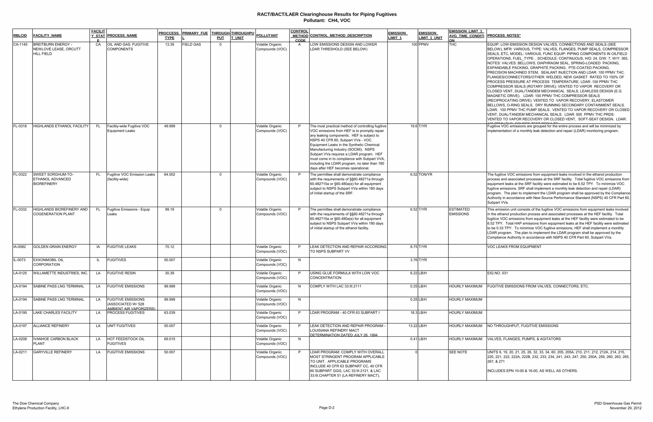
RACT/BACT/LAER Clearinghouse Results for Piping FugitivesPollutant: CH4, VOC
The Dow Chemical CompanyEthylene Production Facility, LHC-9 Page D-2
PSD Greenhouse Gas PermitNovember 29, 2012
RBLCID FACILITY_NAMEFACILITY_STAT
EPROCESS_NAME PROCCESS_
TYPEPRIMARY_FUEL
THROUGH-PUT
THROUGHPUT_UNIT POLLUTANT
CONTROL_METHOD
CODECONTROL_METHOD_DESCRIPTION EMISSION_
LIMIT_1EMISSION_LIMIT_1_UNIT
EMISSION_LIMIT_1_AVG_TIME_CONDITION
PROCESS_NOTES"
CA-1145 BREITBURN ENERGY - NEWLOVE LEASE, ORCUTT HILL FIELD
CA OIL AND GAS: FUGITIVE COMPONENTS
13.39 FIELD GAS 0 Volatile Organic Compounds (VOC)
A LOW EMISSIONS DESIGN AND LOWER LDAR THRESHOLD (SEE BELOW)
100 PPMV THC EQUIP: LOW-EMISSION DESIGN VALVES, CONNECTIONS AND SEALS (SEE BELOW), MFR: VARIOUS, TYPE: VALVES, FLANGES, PUMP SEALS, COMPRESSOR SEALS, ETC, MODEL: VARIOUS, FUNC EQUIP: PIPING COMPONENTS IN OILFIELD OPERATIONS, FUEL_TYPE: , SCHEDULE: CONTINUOUS, H/D: 24, D/W: 7, W/Y: 365, NOTES: VALVES: BELLOWS, DIAPHRAGM SEAL, SPRING-LOADED PACKING, EXPANDABLE PACKING, GRAPHITE PACKING, PTE-COATED PACKING, PRECISION MACHINED STEM, SEALANT INJECTION AND LDAR: 100 PPMV THC. FLANGES/CONNECTORS/OTHER: WELDED, NEW GASKET RATED TO 150% OF PROCESS PRESSURE AT PROCESS TEMPERATURE. LDAR: 100 PPMV THC COMPRESSOR SEALS (ROTARY DRIVE): VENTED TO VAPOR RECOVERY OR CLOSED VENT, DUAL/TANDEM MECHANICAL SEALS, LEAKLESS DESIGN (E.G. MAGNETIC DRIVE). LDAR: 100 PPMV THC COMPRESSOR SEALS (RECIPROCATING DRIVE): VENTED TO VAPOR RECOVERY, ELASTOMER BELLOWS, O-RING SEALS, DRY RUNNING SECONDARY CONTAINMENT SEALS. LDAR: 100 PPMV THC PUMP SEALS: VENTED TO VAPOR RECOVERY OR CLOSED VENT, DUAL/TANDEM MECHANICAL SEALS. LDAR: 500 PPMV THC PRDS: VENTED TO VAPOR RECOVERY OR CLOSED VENT, SOFT-SEAT DESIGN. LDAR: 100 PPMV THC SOURCE TEST RESULTS:FL-0318 HIGHLANDS ETHANOL FACILITY FL Facility-wide Fugitive VOC
Equipment Leaks49.999 0 Volatile Organic
Compounds (VOC)P The most practical method of controlling fugitive
VOC emissions from HEF is to promptly repair any leaking components. HEF is subject to NSPS 40 CFR 60, Subpart VVa - VOC Equipment Leaks in the Synthetic Chemical Manufacturing Industry (SOCMI). NSPS Subpart VVa requires a LDAR program. HEF must come in to compliance with Subpart VVA, including the LDAR program, no later than 180 days after HEF becomes operational.
19.6 T/YR Fugitive VOC emissions are grouped for the entire process and will be minimized by implementation of a monthly leak detection and repair (LDAR) monitoring program.
FL-0322 SWEET SORGHUM-TO-ETHANOL ADVANCED BIOREFINERY
FL Fugitive VOC Emission Leaks (facility-wide)
64.002 0 Volatile Organic Compounds (VOC)
P The permittee shall demonstrate compliance with the requirements of §§60.482?1a through 60.482?10a or §60.480a(e) for all equipment subject to NSPS Subpart VVa within 180 days of initial startup of the SRF.
6.52 TON/YR The fugitive VOC emissions from equipment leaks involved in the ethanol production process and associated processes at the SRF facility. Total fugitive VOC emissions from equipment leaks at the SRF facility were estimated to be 6.52 TPY. To minimize VOC fugitive emissions, SRF shall implement a monthly leak detection and repair (LDAR) program. The plan to implement the LDAR program shall be approved by the Compliance Authority in accordance with New Source Performance Standard (NSPS) 40 CFR Part 60, Subpart VVa.
FL-0332 HIGHLANDS BIOREFINERY AND COGENERATION PLANT
FL Fugitive Emissions - Equip Leaks
99.19 0 Volatile Organic Compounds (VOC)
P The permittee shall demonstrate compliance with the requirements of §§60.482?1a through 60.482?10a or §60.480a(e) for all equipment subject to NSPS Subpart VVa within 180 days of initial startup of the ethanol facility.
6.52 T/YR ESTIMATED EMISSIONS
This emission unit consists of the fugitive VOC emissions from equipment leaks involved in the ethanol production process and associated processes at the HEF facility. Total fugitive VOC emissions from equipment leaks at the HEF facility were estimated to be 6.52 TPY. Total HAP emissions from equipment leaks at the HEF facility were estimated to be 0.33 TPY. To minimize VOC fugitive emissions, HEF shall implement a monthly LDAR program. The plan to implement the LDAR program shall be approved by the Compliance Authority in accordance with NSPS 40 CFR Part 60, Subpart VVa.
IA-0082 GOLDEN GRAIN ENERGY IA FUGITIVE LEAKS 70.12 Volatile Organic Compounds (VOC)
P LEAK DETECTION AND REPAIR ACCORDING TO NSPS SUBPART VV
8.75 T/YR VOC LEAKS FROM EQUIPMENT
IL-0073 EXXONMOBIL OIL CORPORATION
IL FUGITIVES 50.007 Volatile Organic Compounds (VOC)
N 3.76 T/YR
LA-0125 WILLAMETTE INDUSTRIES, INC. LA FUGITIVE RESIN 30.39 Volatile Organic Compounds (VOC)
P USING GLUE FORMULA WITH LOW VOC CONCENTRATION
6.22 LB/H EIQ NO. 031
LA-0194 SABINE PASS LNG TERMINAL LA FUGITIVE EMISSIONS 99.999 Volatile Organic Compounds (VOC)
N COMPLY WITH LAC 33:III.2111 0.25 LB/H HOURLY MAXIMUM FUGITIVE EMISSIONS FROM VALVES, CONNECTORS, ETC.
LA-0194 SABINE PASS LNG TERMINAL LA FUGITIVE EMISSIONS (ASSOCIATED W/ 528 AMBIENT AIR VAPORIZERS)
99.999 Volatile Organic Compounds (VOC)
N 0.25 LB/H HOURLY MAXIMUM
LA-0195 LAKE CHARLES FACILITY LA PROCESS FUGITIVES 63.039 Volatile Organic Compounds (VOC)
P LDAR PROGRAM - 40 CFR 63 SUBPART I 18.3 LB/H HOURLY MAXIMUM
LA-0197 ALLIANCE REFINERY LA UNIT FUGITIVES 50.007 Volatile Organic Compounds (VOC)
P LEAK DETECTION AND REPAIR PROGRAM - LOUISIANA REFINERY MACT DETERMINATION DATED JULY 26, 1994
13.22 LB/H HOURLY MAXIMUM NO THROUGHPUT, FUGITIVE EMISSIONS
LA-0208 IVANHOE CARBON BLACK PLANT
LA HOT FEEDSTOCK OIL FUGITIVES
69.015 Volatile Organic Compounds (VOC)
N 0.41 LB/H HOURLY MAXIMUM VALVES, FLANGES, PUMPS, & AGITATORS
LA-0211 GARYVILLE REFINERY LA FUGITIVE EMISSIONS 50.007 Volatile Organic Compounds (VOC)
P LDAR PROGRAM: COMPLY WITH OVERALL MOST STRINGENT PROGRAM APPLICABLE TO UNIT. APPLICABLE PROGRAMS INCLUDE 40 CFR 63 SUBPART CC, 40 CFR 60 SUBPART GGG, LAC 33:III.2121, & LAC 33:III.CHAPTER 51 (LA REFINERY MACT).
0 SEE NOTE UNITS 9, 19, 20, 21, 25, 26, 32, 33, 34, 60, 205, 205A, 210, 211, 212, 212A, 214, 215, 220, 221, 222, 222A, 222B, 232, 233, 234, 241, 243, 247, 250, 250A, 259, 260, 263, 265, 267, & 271 INCLUDES EPN 10-00 & 16-00, AS WELL AS OTHERS.
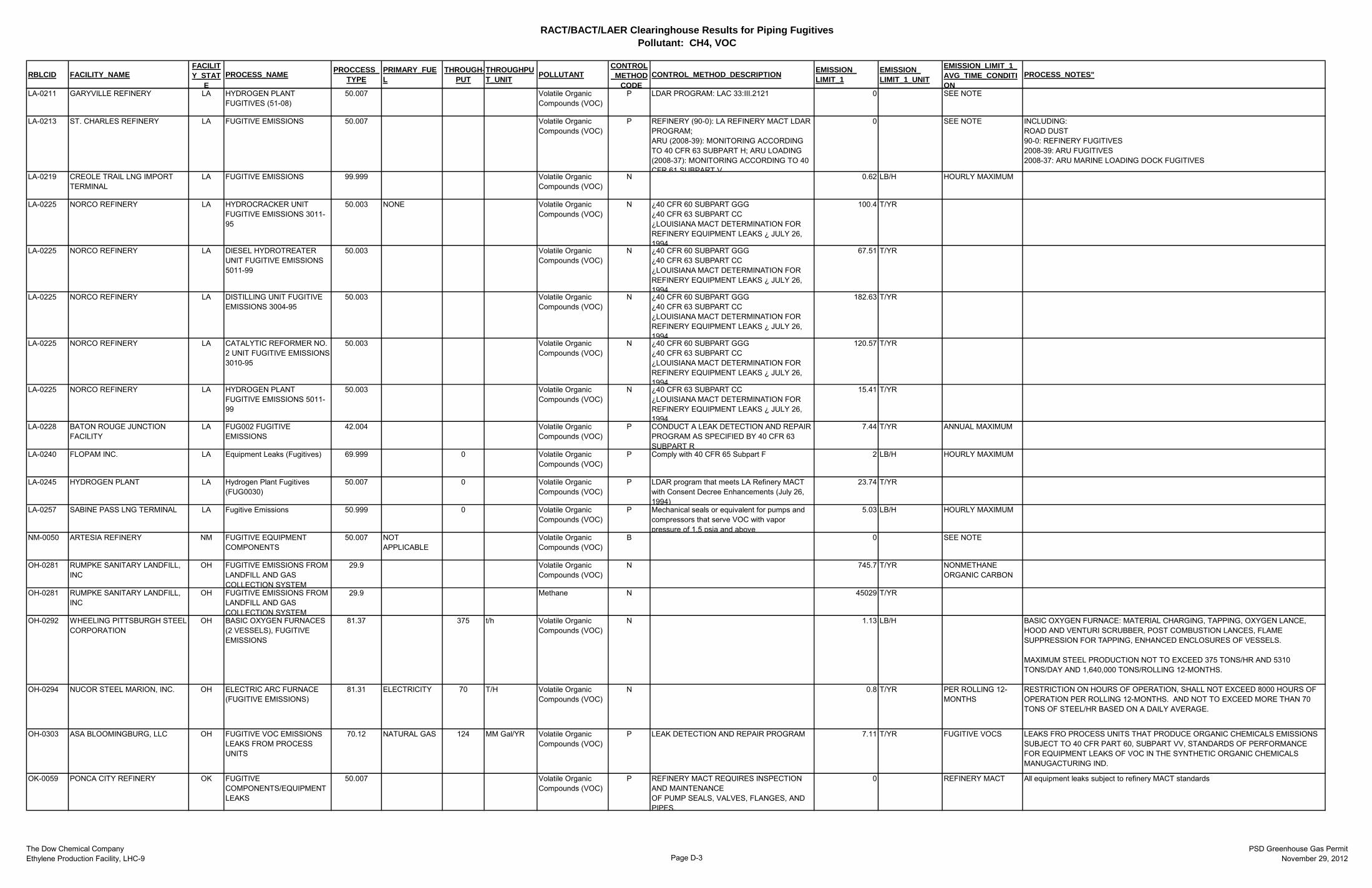
RACT/BACT/LAER Clearinghouse Results for Piping FugitivesPollutant: CH4, VOC
The Dow Chemical CompanyEthylene Production Facility, LHC-9 Page D-3
PSD Greenhouse Gas PermitNovember 29, 2012
RBLCID FACILITY_NAMEFACILITY_STAT
EPROCESS_NAME PROCCESS_
TYPEPRIMARY_FUEL
THROUGH-PUT
THROUGHPUT_UNIT POLLUTANT
CONTROL_METHOD
CODECONTROL_METHOD_DESCRIPTION EMISSION_
LIMIT_1EMISSION_LIMIT_1_UNIT
EMISSION_LIMIT_1_AVG_TIME_CONDITION
PROCESS_NOTES"
LA-0211 GARYVILLE REFINERY LA HYDROGEN PLANT FUGITIVES (51-08)
50.007 Volatile Organic Compounds (VOC)
P LDAR PROGRAM: LAC 33:III.2121 0 SEE NOTE
LA-0213 ST. CHARLES REFINERY LA FUGITIVE EMISSIONS 50.007 Volatile Organic Compounds (VOC)
P REFINERY (90-0): LA REFINERY MACT LDAR PROGRAM; ARU (2008-39): MONITORING ACCORDING TO 40 CFR 63 SUBPART H; ARU LOADING (2008-37): MONITORING ACCORDING TO 40 CFR 61 SUBPART V
0 SEE NOTE INCLUDING: ROAD DUST 90-0: REFINERY FUGITIVES 2008-39: ARU FUGITIVES 2008-37: ARU MARINE LOADING DOCK FUGITIVES
LA-0219 CREOLE TRAIL LNG IMPORT TERMINAL
LA FUGITIVE EMISSIONS 99.999 Volatile Organic Compounds (VOC)
N 0.62 LB/H HOURLY MAXIMUM
LA-0225 NORCO REFINERY LA HYDROCRACKER UNIT FUGITIVE EMISSIONS 3011-95
50.003 NONE Volatile Organic Compounds (VOC)
N ¿40 CFR 60 SUBPART GGG ¿40 CFR 63 SUBPART CC ¿LOUISIANA MACT DETERMINATION FOR REFINERY EQUIPMENT LEAKS ¿ JULY 26, 1994
100.4 T/YR
LA-0225 NORCO REFINERY LA DIESEL HYDROTREATER UNIT FUGITIVE EMISSIONS 5011-99
50.003 Volatile Organic Compounds (VOC)
N ¿40 CFR 60 SUBPART GGG ¿40 CFR 63 SUBPART CC ¿LOUISIANA MACT DETERMINATION FOR REFINERY EQUIPMENT LEAKS ¿ JULY 26, 1994
67.51 T/YR
LA-0225 NORCO REFINERY LA DISTILLING UNIT FUGITIVE EMISSIONS 3004-95
50.003 Volatile Organic Compounds (VOC)
N ¿40 CFR 60 SUBPART GGG ¿40 CFR 63 SUBPART CC ¿LOUISIANA MACT DETERMINATION FOR REFINERY EQUIPMENT LEAKS ¿ JULY 26, 1994
182.63 T/YR
LA-0225 NORCO REFINERY LA CATALYTIC REFORMER NO. 2 UNIT FUGITIVE EMISSIONS 3010-95
50.003 Volatile Organic Compounds (VOC)
N ¿40 CFR 60 SUBPART GGG ¿40 CFR 63 SUBPART CC ¿LOUISIANA MACT DETERMINATION FOR REFINERY EQUIPMENT LEAKS ¿ JULY 26, 1994
120.57 T/YR
LA-0225 NORCO REFINERY LA HYDROGEN PLANT FUGITIVE EMISSIONS 5011-99
50.003 Volatile Organic Compounds (VOC)
N ¿40 CFR 63 SUBPART CC ¿LOUISIANA MACT DETERMINATION FOR REFINERY EQUIPMENT LEAKS ¿ JULY 26, 1994
15.41 T/YR
LA-0228 BATON ROUGE JUNCTION FACILITY
LA FUG002 FUGITIVE EMISSIONS
42.004 Volatile Organic Compounds (VOC)
P CONDUCT A LEAK DETECTION AND REPAIR PROGRAM AS SPECIFIED BY 40 CFR 63 SUBPART R
7.44 T/YR ANNUAL MAXIMUM
LA-0240 FLOPAM INC. LA Equipment Leaks (Fugitives) 69.999 0 Volatile Organic Compounds (VOC)
P Comply with 40 CFR 65 Subpart F 2 LB/H HOURLY MAXIMUM
LA-0245 HYDROGEN PLANT LA Hydrogen Plant Fugitives (FUG0030)
50.007 0 Volatile Organic Compounds (VOC)
P LDAR program that meets LA Refinery MACT with Consent Decree Enhancements (July 26, 1994)
23.74 T/YR
LA-0257 SABINE PASS LNG TERMINAL LA Fugitive Emissions 50.999 0 Volatile Organic Compounds (VOC)
P Mechanical seals or equivalent for pumps and compressors that serve VOC with vapor pressure of 1.5 psia and above
5.03 LB/H HOURLY MAXIMUM
NM-0050 ARTESIA REFINERY NM FUGITIVE EQUIPMENT COMPONENTS
50.007 NOT APPLICABLE
Volatile Organic Compounds (VOC)
B 0 SEE NOTE
OH-0281 RUMPKE SANITARY LANDFILL, INC
OH FUGITIVE EMISSIONS FROM LANDFILL AND GAS COLLECTION SYSTEM
29.9 Volatile Organic Compounds (VOC)
N 745.7 T/YR NONMETHANE ORGANIC CARBON
OH-0281 RUMPKE SANITARY LANDFILL, INC
OH FUGITIVE EMISSIONS FROM LANDFILL AND GAS COLLECTION SYSTEM
29.9 Methane N 45029 T/YR
OH-0292 WHEELING PITTSBURGH STEEL CORPORATION
OH BASIC OXYGEN FURNACES (2 VESSELS), FUGITIVE EMISSIONS
81.37 375 t/h Volatile Organic Compounds (VOC)
N 1.13 LB/H BASIC OXYGEN FURNACE: MATERIAL CHARGING, TAPPING, OXYGEN LANCE, HOOD AND VENTURI SCRUBBER, POST COMBUSTION LANCES, FLAME SUPPRESSION FOR TAPPING, ENHANCED ENCLOSURES OF VESSELS. MAXIMUM STEEL PRODUCTION NOT TO EXCEED 375 TONS/HR AND 5310 TONS/DAY AND 1,640,000 TONS/ROLLING 12-MONTHS.
OH-0294 NUCOR STEEL MARION, INC. OH ELECTRIC ARC FURNACE (FUGITIVE EMISSIONS)
81.31 ELECTRICITY 70 T/H Volatile Organic Compounds (VOC)
N 0.8 T/YR PER ROLLING 12-MONTHS
RESTRICTION ON HOURS OF OPERATION, SHALL NOT EXCEED 8000 HOURS OF OPERATION PER ROLLING 12-MONTHS. AND NOT TO EXCEED MORE THAN 70 TONS OF STEEL/HR BASED ON A DAILY AVERAGE.
OH-0303 ASA BLOOMINGBURG, LLC OH FUGITIVE VOC EMISSIONS LEAKS FROM PROCESS UNITS
70.12 NATURAL GAS 124 MM Gal/YR Volatile Organic Compounds (VOC)
P LEAK DETECTION AND REPAIR PROGRAM 7.11 T/YR FUGITIVE VOCS LEAKS FRO PROCESS UNITS THAT PRODUCE ORGANIC CHEMICALS EMISSIONS SUBJECT TO 40 CFR PART 60, SUBPART VV, STANDARDS OF PERFORMANCE FOR EQUIPMENT LEAKS OF VOC IN THE SYNTHETIC ORGANIC CHEMICALS MANUGACTURING IND.
OK-0059 PONCA CITY REFINERY OK FUGITIVE COMPONENTS/EQUIPMENT LEAKS
50.007 Volatile Organic Compounds (VOC)
P REFINERY MACT REQUIRES INSPECTION AND MAINTENANCE OF PUMP SEALS, VALVES, FLANGES, AND PIPES.
0 REFINERY MACT All equipment leaks subject to refinery MACT standards
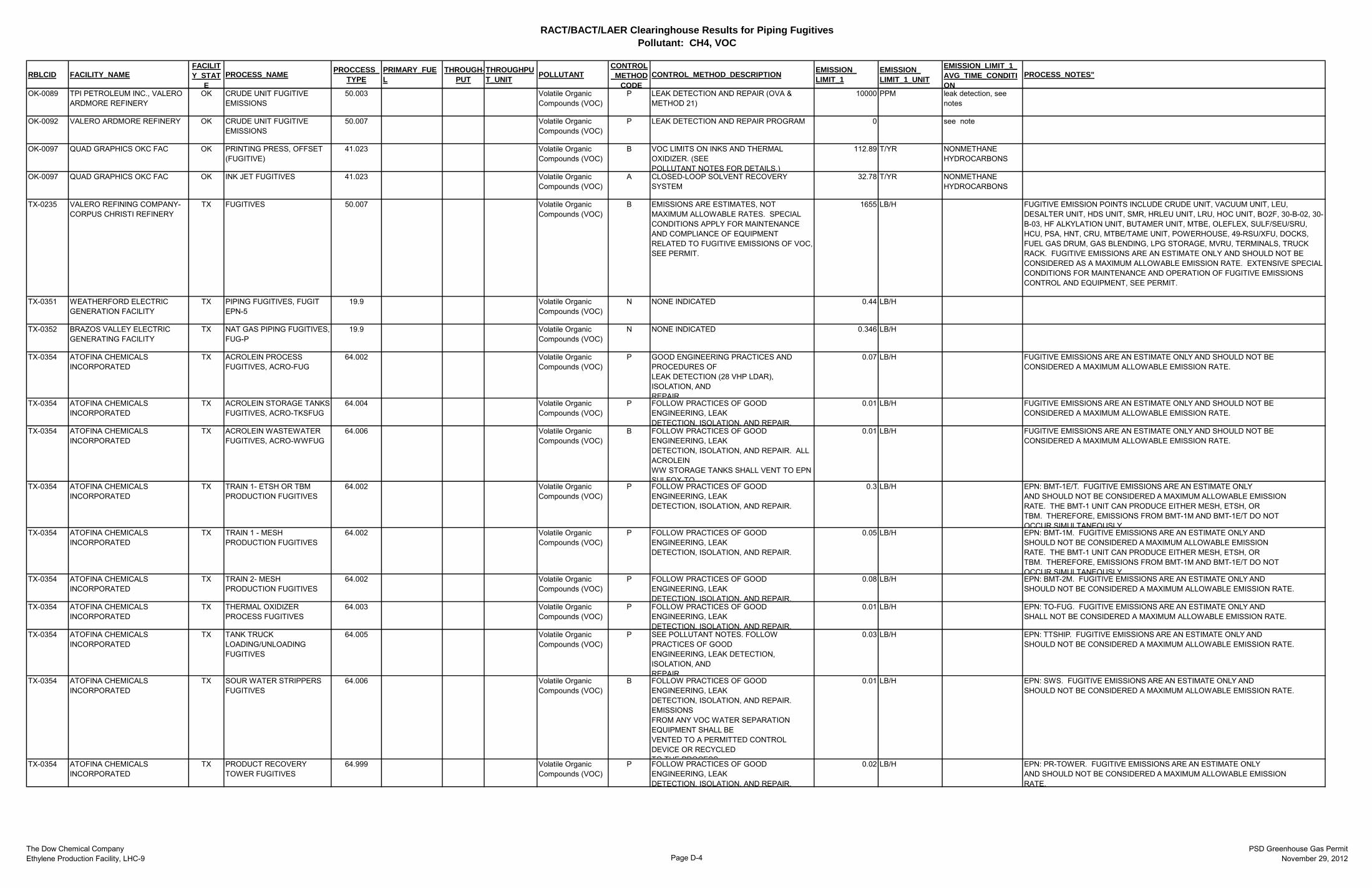
RACT/BACT/LAER Clearinghouse Results for Piping FugitivesPollutant: CH4, VOC
The Dow Chemical CompanyEthylene Production Facility, LHC-9 Page D-4
PSD Greenhouse Gas PermitNovember 29, 2012
RBLCID FACILITY_NAMEFACILITY_STAT
EPROCESS_NAME PROCCESS_
TYPEPRIMARY_FUEL
THROUGH-PUT
THROUGHPUT_UNIT POLLUTANT
CONTROL_METHOD
CODECONTROL_METHOD_DESCRIPTION EMISSION_
LIMIT_1EMISSION_LIMIT_1_UNIT
EMISSION_LIMIT_1_AVG_TIME_CONDITION
PROCESS_NOTES"
OK-0089 TPI PETROLEUM INC., VALERO ARDMORE REFINERY
OK CRUDE UNIT FUGITIVE EMISSIONS
50.003 Volatile Organic Compounds (VOC)
P LEAK DETECTION AND REPAIR (OVA & METHOD 21)
10000 PPM leak detection, see notes
OK-0092 VALERO ARDMORE REFINERY OK CRUDE UNIT FUGITIVE EMISSIONS
50.007 Volatile Organic Compounds (VOC)
P LEAK DETECTION AND REPAIR PROGRAM 0 see note
OK-0097 QUAD GRAPHICS OKC FAC OK PRINTING PRESS, OFFSET (FUGITIVE)
41.023 Volatile Organic Compounds (VOC)
B VOC LIMITS ON INKS AND THERMAL OXIDIZER. (SEE POLLUTANT NOTES FOR DETAILS.)
112.89 T/YR NONMETHANE HYDROCARBONS
OK-0097 QUAD GRAPHICS OKC FAC OK INK JET FUGITIVES 41.023 Volatile Organic Compounds (VOC)
A CLOSED-LOOP SOLVENT RECOVERY SYSTEM
32.78 T/YR NONMETHANE HYDROCARBONS
TX-0235 VALERO REFINING COMPANY- CORPUS CHRISTI REFINERY
TX FUGITIVES 50.007 Volatile Organic Compounds (VOC)
B EMISSIONS ARE ESTIMATES, NOT MAXIMUM ALLOWABLE RATES. SPECIAL CONDITIONS APPLY FOR MAINTENANCE AND COMPLIANCE OF EQUIPMENT RELATED TO FUGITIVE EMISSIONS OF VOC, SEE PERMIT.
1655 LB/H FUGITIVE EMISSION POINTS INCLUDE CRUDE UNIT, VACUUM UNIT, LEU, DESALTER UNIT, HDS UNIT, SMR, HRLEU UNIT, LRU, HOC UNIT, BO2F, 30-B-02, 30-B-03, HF ALKYLATION UNIT, BUTAMER UNIT, MTBE, OLEFLEX, SULF/SEU/SRU, HCU, PSA, HNT, CRU, MTBE/TAME UNIT, POWERHOUSE, 49-RSU/XFU, DOCKS, FUEL GAS DRUM, GAS BLENDING, LPG STORAGE, MVRU, TERMINALS, TRUCK RACK. FUGITIVE EMISSIONS ARE AN ESTIMATE ONLY AND SHOULD NOT BE CONSIDERED AS A MAXIMUM ALLOWABLE EMISSION RATE. EXTENSIVE SPECIAL CONDITIONS FOR MAINTENANCE AND OPERATION OF FUGITIVE EMISSIONS CONTROL AND EQUIPMENT, SEE PERMIT.
TX-0351 WEATHERFORD ELECTRIC GENERATION FACILITY
TX PIPING FUGITIVES, FUGIT EPN-5
19.9 Volatile Organic Compounds (VOC)
N NONE INDICATED 0.44 LB/H
TX-0352 BRAZOS VALLEY ELECTRIC GENERATING FACILITY
TX NAT GAS PIPING FUGITIVES, FUG-P
19.9 Volatile Organic Compounds (VOC)
N NONE INDICATED 0.346 LB/H
TX-0354 ATOFINA CHEMICALS INCORPORATED
TX ACROLEIN PROCESS FUGITIVES, ACRO-FUG
64.002 Volatile Organic Compounds (VOC)
P GOOD ENGINEERING PRACTICES AND PROCEDURES OF LEAK DETECTION (28 VHP LDAR), ISOLATION, AND REPAIR
0.07 LB/H FUGITIVE EMISSIONS ARE AN ESTIMATE ONLY AND SHOULD NOT BE CONSIDERED A MAXIMUM ALLOWABLE EMISSION RATE.
TX-0354 ATOFINA CHEMICALS INCORPORATED
TX ACROLEIN STORAGE TANKS FUGITIVES, ACRO-TKSFUG
64.004 Volatile Organic Compounds (VOC)
P FOLLOW PRACTICES OF GOOD ENGINEERING, LEAK DETECTION, ISOLATION, AND REPAIR.
0.01 LB/H FUGITIVE EMISSIONS ARE AN ESTIMATE ONLY AND SHOULD NOT BE CONSIDERED A MAXIMUM ALLOWABLE EMISSION RATE.
TX-0354 ATOFINA CHEMICALS INCORPORATED
TX ACROLEIN WASTEWATER FUGITIVES, ACRO-WWFUG
64.006 Volatile Organic Compounds (VOC)
B FOLLOW PRACTICES OF GOOD ENGINEERING, LEAK DETECTION, ISOLATION, AND REPAIR. ALL ACROLEIN WW STORAGE TANKS SHALL VENT TO EPN SULFOX-TO
0.01 LB/H FUGITIVE EMISSIONS ARE AN ESTIMATE ONLY AND SHOULD NOT BE CONSIDERED A MAXIMUM ALLOWABLE EMISSION RATE.
TX-0354 ATOFINA CHEMICALS INCORPORATED
TX TRAIN 1- ETSH OR TBM PRODUCTION FUGITIVES
64.002 Volatile Organic Compounds (VOC)
P FOLLOW PRACTICES OF GOOD ENGINEERING, LEAK DETECTION, ISOLATION, AND REPAIR.
0.3 LB/H EPN: BMT-1E/T. FUGITIVE EMISSIONS ARE AN ESTIMATE ONLY AND SHOULD NOT BE CONSIDERED A MAXIMUM ALLOWABLE EMISSION RATE. THE BMT-1 UNIT CAN PRODUCE EITHER MESH, ETSH, OR TBM. THEREFORE, EMISSIONS FROM BMT-1M AND BMT-1E/T DO NOT OCCUR SIMULTANEOUSLY
TX-0354 ATOFINA CHEMICALS INCORPORATED
TX TRAIN 1 - MESH PRODUCTION FUGITIVES
64.002 Volatile Organic Compounds (VOC)
P FOLLOW PRACTICES OF GOOD ENGINEERING, LEAK DETECTION, ISOLATION, AND REPAIR.
0.05 LB/H EPN: BMT-1M. FUGITIVE EMISSIONS ARE AN ESTIMATE ONLY AND SHOULD NOT BE CONSIDERED A MAXIMUM ALLOWABLE EMISSION RATE. THE BMT-1 UNIT CAN PRODUCE EITHER MESH, ETSH, OR TBM. THEREFORE, EMISSIONS FROM BMT-1M AND BMT-1E/T DO NOT OCCUR SIMULTANEOUSLY
TX-0354 ATOFINA CHEMICALS INCORPORATED
TX TRAIN 2- MESH PRODUCTION FUGITIVES
64.002 Volatile Organic Compounds (VOC)
P FOLLOW PRACTICES OF GOOD ENGINEERING, LEAK DETECTION, ISOLATION, AND REPAIR.
0.08 LB/H EPN: BMT-2M. FUGITIVE EMISSIONS ARE AN ESTIMATE ONLY AND SHOULD NOT BE CONSIDERED A MAXIMUM ALLOWABLE EMISSION RATE.
TX-0354 ATOFINA CHEMICALS INCORPORATED
TX THERMAL OXIDIZER PROCESS FUGITIVES
64.003 Volatile Organic Compounds (VOC)
P FOLLOW PRACTICES OF GOOD ENGINEERING, LEAK DETECTION, ISOLATION, AND REPAIR.
0.01 LB/H EPN: TO-FUG. FUGITIVE EMISSIONS ARE AN ESTIMATE ONLY AND SHALL NOT BE CONSIDERED A MAXIMUM ALLOWABLE EMISSION RATE.
TX-0354 ATOFINA CHEMICALS INCORPORATED
TX TANK TRUCK LOADING/UNLOADING FUGITIVES
64.005 Volatile Organic Compounds (VOC)
P SEE POLLUTANT NOTES. FOLLOW PRACTICES OF GOOD ENGINEERING, LEAK DETECTION, ISOLATION, AND REPAIR
0.03 LB/H EPN: TTSHIP. FUGITIVE EMISSIONS ARE AN ESTIMATE ONLY AND SHOULD NOT BE CONSIDERED A MAXIMUM ALLOWABLE EMISSION RATE.
TX-0354 ATOFINA CHEMICALS INCORPORATED
TX SOUR WATER STRIPPERS FUGITIVES
64.006 Volatile Organic Compounds (VOC)
B FOLLOW PRACTICES OF GOOD ENGINEERING, LEAK DETECTION, ISOLATION, AND REPAIR. EMISSIONS FROM ANY VOC WATER SEPARATION EQUIPMENT SHALL BE VENTED TO A PERMITTED CONTROL DEVICE OR RECYCLED TO THE PROCESS
0.01 LB/H EPN: SWS. FUGITIVE EMISSIONS ARE AN ESTIMATE ONLY AND SHOULD NOT BE CONSIDERED A MAXIMUM ALLOWABLE EMISSION RATE.
TX-0354 ATOFINA CHEMICALS INCORPORATED
TX PRODUCT RECOVERY TOWER FUGITIVES
64.999 Volatile Organic Compounds (VOC)
P FOLLOW PRACTICES OF GOOD ENGINEERING, LEAK DETECTION, ISOLATION, AND REPAIR.
0.02 LB/H EPN: PR-TOWER. FUGITIVE EMISSIONS ARE AN ESTIMATE ONLY AND SHOULD NOT BE CONSIDERED A MAXIMUM ALLOWABLE EMISSION RATE.
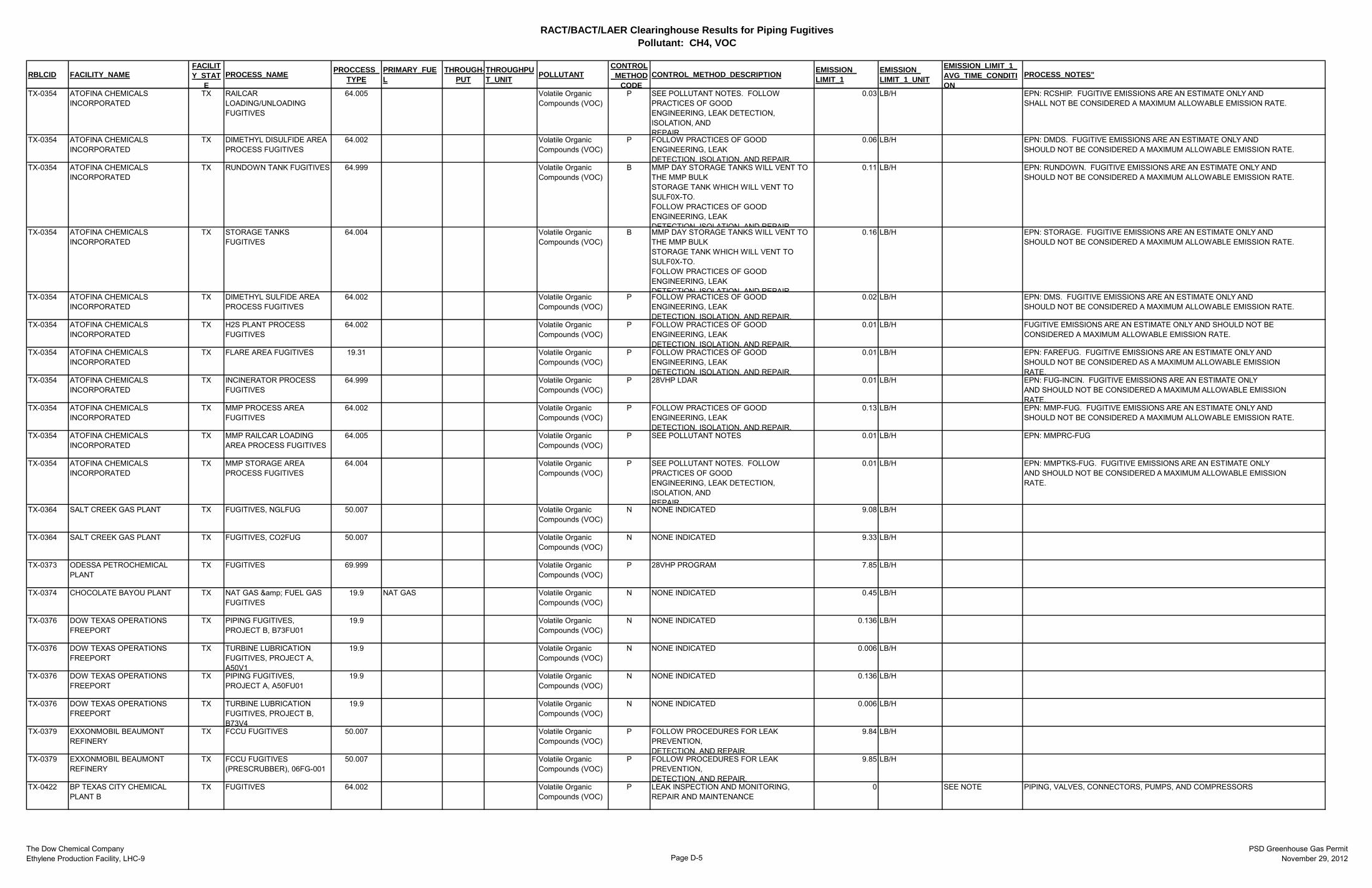
RACT/BACT/LAER Clearinghouse Results for Piping FugitivesPollutant: CH4, VOC
The Dow Chemical CompanyEthylene Production Facility, LHC-9 Page D-5
PSD Greenhouse Gas PermitNovember 29, 2012
RBLCID FACILITY_NAMEFACILITY_STAT
EPROCESS_NAME PROCCESS_
TYPEPRIMARY_FUEL
THROUGH-PUT
THROUGHPUT_UNIT POLLUTANT
CONTROL_METHOD
CODECONTROL_METHOD_DESCRIPTION EMISSION_
LIMIT_1EMISSION_LIMIT_1_UNIT
EMISSION_LIMIT_1_AVG_TIME_CONDITION
PROCESS_NOTES"
TX-0354 ATOFINA CHEMICALS INCORPORATED
TX RAILCAR LOADING/UNLOADING FUGITIVES
64.005 Volatile Organic Compounds (VOC)
P SEE POLLUTANT NOTES. FOLLOW PRACTICES OF GOOD ENGINEERING, LEAK DETECTION, ISOLATION, AND REPAIR
0.03 LB/H EPN: RCSHIP. FUGITIVE EMISSIONS ARE AN ESTIMATE ONLY AND SHALL NOT BE CONSIDERED A MAXIMUM ALLOWABLE EMISSION RATE.
TX-0354 ATOFINA CHEMICALS INCORPORATED
TX DIMETHYL DISULFIDE AREA PROCESS FUGITIVES
64.002 Volatile Organic Compounds (VOC)
P FOLLOW PRACTICES OF GOOD ENGINEERING, LEAK DETECTION, ISOLATION, AND REPAIR.
0.06 LB/H EPN: DMDS. FUGITIVE EMISSIONS ARE AN ESTIMATE ONLY AND SHOULD NOT BE CONSIDERED A MAXIMUM ALLOWABLE EMISSION RATE.
TX-0354 ATOFINA CHEMICALS INCORPORATED
TX RUNDOWN TANK FUGITIVES 64.999 Volatile Organic Compounds (VOC)
B MMP DAY STORAGE TANKS WILL VENT TO THE MMP BULK STORAGE TANK WHICH WILL VENT TO SULF0X-TO. FOLLOW PRACTICES OF GOOD ENGINEERING, LEAK DETECTION ISOLATION AND REPAIR
0.11 LB/H EPN: RUNDOWN. FUGITIVE EMISSIONS ARE AN ESTIMATE ONLY AND SHOULD NOT BE CONSIDERED A MAXIMUM ALLOWABLE EMISSION RATE.
TX-0354 ATOFINA CHEMICALS INCORPORATED
TX STORAGE TANKS FUGITIVES
64.004 Volatile Organic Compounds (VOC)
B MMP DAY STORAGE TANKS WILL VENT TO THE MMP BULK STORAGE TANK WHICH WILL VENT TO SULF0X-TO. FOLLOW PRACTICES OF GOOD ENGINEERING, LEAK DETECTION ISOLATION AND REPAIR
0.16 LB/H EPN: STORAGE. FUGITIVE EMISSIONS ARE AN ESTIMATE ONLY AND SHOULD NOT BE CONSIDERED A MAXIMUM ALLOWABLE EMISSION RATE.
TX-0354 ATOFINA CHEMICALS INCORPORATED
TX DIMETHYL SULFIDE AREA PROCESS FUGITIVES
64.002 Volatile Organic Compounds (VOC)
P FOLLOW PRACTICES OF GOOD ENGINEERING, LEAK DETECTION, ISOLATION, AND REPAIR.
0.02 LB/H EPN: DMS. FUGITIVE EMISSIONS ARE AN ESTIMATE ONLY AND SHOULD NOT BE CONSIDERED A MAXIMUM ALLOWABLE EMISSION RATE.
TX-0354 ATOFINA CHEMICALS INCORPORATED
TX H2S PLANT PROCESS FUGITIVES
64.002 Volatile Organic Compounds (VOC)
P FOLLOW PRACTICES OF GOOD ENGINEERING, LEAK DETECTION, ISOLATION, AND REPAIR.
0.01 LB/H FUGITIVE EMISSIONS ARE AN ESTIMATE ONLY AND SHOULD NOT BE CONSIDERED A MAXIMUM ALLOWABLE EMISSION RATE.
TX-0354 ATOFINA CHEMICALS INCORPORATED
TX FLARE AREA FUGITIVES 19.31 Volatile Organic Compounds (VOC)
P FOLLOW PRACTICES OF GOOD ENGINEERING, LEAK DETECTION, ISOLATION, AND REPAIR.
0.01 LB/H EPN: FAREFUG. FUGITIVE EMISSIONS ARE AN ESTIMATE ONLY AND SHOULD NOT BE CONSIDERED AS A MAXIMUM ALLOWABLE EMISSION RATE.
TX-0354 ATOFINA CHEMICALS INCORPORATED
TX INCINERATOR PROCESS FUGITIVES
64.999 Volatile Organic Compounds (VOC)
P 28VHP LDAR 0.01 LB/H EPN: FUG-INCIN. FUGITIVE EMISSIONS ARE AN ESTIMATE ONLY AND SHOULD NOT BE CONSIDERED A MAXIMUM ALLOWABLE EMISSION RATE.
TX-0354 ATOFINA CHEMICALS INCORPORATED
TX MMP PROCESS AREA FUGITIVES
64.002 Volatile Organic Compounds (VOC)
P FOLLOW PRACTICES OF GOOD ENGINEERING, LEAK DETECTION, ISOLATION, AND REPAIR.
0.13 LB/H EPN: MMP-FUG. FUGITIVE EMISSIONS ARE AN ESTIMATE ONLY AND SHOULD NOT BE CONSIDERED A MAXIMUM ALLOWABLE EMISSION RATE.
TX-0354 ATOFINA CHEMICALS INCORPORATED
TX MMP RAILCAR LOADING AREA PROCESS FUGITIVES
64.005 Volatile Organic Compounds (VOC)
P SEE POLLUTANT NOTES 0.01 LB/H EPN: MMPRC-FUG
TX-0354 ATOFINA CHEMICALS INCORPORATED
TX MMP STORAGE AREA PROCESS FUGITIVES
64.004 Volatile Organic Compounds (VOC)
P SEE POLLUTANT NOTES. FOLLOW PRACTICES OF GOOD ENGINEERING, LEAK DETECTION, ISOLATION, AND REPAIR
0.01 LB/H EPN: MMPTKS-FUG. FUGITIVE EMISSIONS ARE AN ESTIMATE ONLY AND SHOULD NOT BE CONSIDERED A MAXIMUM ALLOWABLE EMISSION RATE.
TX-0364 SALT CREEK GAS PLANT TX FUGITIVES, NGLFUG 50.007 Volatile Organic Compounds (VOC)
N NONE INDICATED 9.08 LB/H
TX-0364 SALT CREEK GAS PLANT TX FUGITIVES, CO2FUG 50.007 Volatile Organic Compounds (VOC)
N NONE INDICATED 9.33 LB/H
TX-0373 ODESSA PETROCHEMICAL PLANT
TX FUGITIVES 69.999 Volatile Organic Compounds (VOC)
P 28VHP PROGRAM 7.85 LB/H
TX-0374 CHOCOLATE BAYOU PLANT TX NAT GAS & FUEL GAS FUGITIVES
19.9 NAT GAS Volatile Organic Compounds (VOC)
N NONE INDICATED 0.45 LB/H
TX-0376 DOW TEXAS OPERATIONS FREEPORT
TX PIPING FUGITIVES, PROJECT B, B73FU01
19.9 Volatile Organic Compounds (VOC)
N NONE INDICATED 0.136 LB/H
TX-0376 DOW TEXAS OPERATIONS FREEPORT
TX TURBINE LUBRICATION FUGITIVES, PROJECT A, A50V1
19.9 Volatile Organic Compounds (VOC)
N NONE INDICATED 0.006 LB/H
TX-0376 DOW TEXAS OPERATIONS FREEPORT
TX PIPING FUGITIVES, PROJECT A, A50FU01
19.9 Volatile Organic Compounds (VOC)
N NONE INDICATED 0.136 LB/H
TX-0376 DOW TEXAS OPERATIONS FREEPORT
TX TURBINE LUBRICATION FUGITIVES, PROJECT B, B73V4
19.9 Volatile Organic Compounds (VOC)
N NONE INDICATED 0.006 LB/H
TX-0379 EXXONMOBIL BEAUMONT REFINERY
TX FCCU FUGITIVES 50.007 Volatile Organic Compounds (VOC)
P FOLLOW PROCEDURES FOR LEAK PREVENTION, DETECTION, AND REPAIR.
9.84 LB/H
TX-0379 EXXONMOBIL BEAUMONT REFINERY
TX FCCU FUGITIVES (PRESCRUBBER), 06FG-001
50.007 Volatile Organic Compounds (VOC)
P FOLLOW PROCEDURES FOR LEAK PREVENTION, DETECTION, AND REPAIR.
9.85 LB/H
TX-0422 BP TEXAS CITY CHEMICAL PLANT B
TX FUGITIVES 64.002 Volatile Organic Compounds (VOC)
P LEAK INSPECTION AND MONITORING, REPAIR AND MAINTENANCE
0 SEE NOTE PIPING, VALVES, CONNECTORS, PUMPS, AND COMPRESSORS
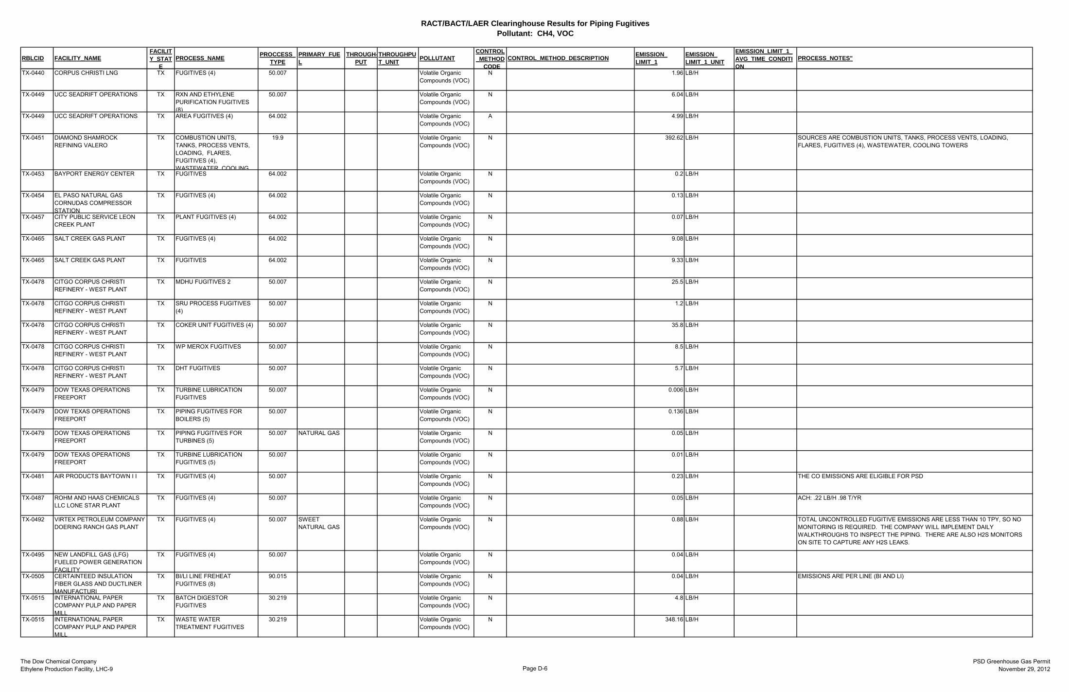
RACT/BACT/LAER Clearinghouse Results for Piping FugitivesPollutant: CH4, VOC
The Dow Chemical CompanyEthylene Production Facility, LHC-9 Page D-6
PSD Greenhouse Gas PermitNovember 29, 2012
RBLCID FACILITY_NAMEFACILITY_STAT
EPROCESS_NAME PROCCESS_
TYPEPRIMARY_FUEL
THROUGH-PUT
THROUGHPUT_UNIT POLLUTANT
CONTROL_METHOD
CODECONTROL_METHOD_DESCRIPTION EMISSION_
LIMIT_1EMISSION_LIMIT_1_UNIT
EMISSION_LIMIT_1_AVG_TIME_CONDITION
PROCESS_NOTES"
TX-0440 CORPUS CHRISTI LNG TX FUGITIVES (4) 50.007 Volatile Organic Compounds (VOC)
N 1.96 LB/H
TX-0449 UCC SEADRIFT OPERATIONS TX RXN AND ETHYLENE PURIFICATION FUGITIVES (8)
50.007 Volatile Organic Compounds (VOC)
N 6.04 LB/H
TX-0449 UCC SEADRIFT OPERATIONS TX AREA FUGITIVES (4) 64.002 Volatile Organic Compounds (VOC)
A 4.99 LB/H
TX-0451 DIAMOND SHAMROCK REFINING VALERO
TX COMBUSTION UNITS, TANKS, PROCESS VENTS, LOADING, FLARES, FUGITIVES (4), WASTEWATER COOLING
19.9 Volatile Organic Compounds (VOC)
N 392.62 LB/H SOURCES ARE COMBUSTION UNITS, TANKS, PROCESS VENTS, LOADING, FLARES, FUGITIVES (4), WASTEWATER, COOLING TOWERS
TX-0453 BAYPORT ENERGY CENTER TX FUGITIVES 64.002 Volatile Organic Compounds (VOC)
N 0.2 LB/H
TX-0454 EL PASO NATURAL GAS CORNUDAS COMPRESSOR STATION
TX FUGITIVES (4) 64.002 Volatile Organic Compounds (VOC)
N 0.13 LB/H
TX-0457 CITY PUBLIC SERVICE LEON CREEK PLANT
TX PLANT FUGITIVES (4) 64.002 Volatile Organic Compounds (VOC)
N 0.07 LB/H
TX-0465 SALT CREEK GAS PLANT TX FUGITIVES (4) 64.002 Volatile Organic Compounds (VOC)
N 9.08 LB/H
TX-0465 SALT CREEK GAS PLANT TX FUGITIVES 64.002 Volatile Organic Compounds (VOC)
N 9.33 LB/H
TX-0478 CITGO CORPUS CHRISTI REFINERY - WEST PLANT
TX MDHU FUGITIVES 2 50.007 Volatile Organic Compounds (VOC)
N 25.5 LB/H
TX-0478 CITGO CORPUS CHRISTI REFINERY - WEST PLANT
TX SRU PROCESS FUGITIVES (4)
50.007 Volatile Organic Compounds (VOC)
N 1.2 LB/H
TX-0478 CITGO CORPUS CHRISTI REFINERY - WEST PLANT
TX COKER UNIT FUGITIVES (4) 50.007 Volatile Organic Compounds (VOC)
N 35.8 LB/H
TX-0478 CITGO CORPUS CHRISTI REFINERY - WEST PLANT
TX WP MEROX FUGITIVES 50.007 Volatile Organic Compounds (VOC)
N 8.5 LB/H
TX-0478 CITGO CORPUS CHRISTI REFINERY - WEST PLANT
TX DHT FUGITIVES 50.007 Volatile Organic Compounds (VOC)
N 5.7 LB/H
TX-0479 DOW TEXAS OPERATIONS FREEPORT
TX TURBINE LUBRICATION FUGITIVES
50.007 Volatile Organic Compounds (VOC)
N 0.006 LB/H
TX-0479 DOW TEXAS OPERATIONS FREEPORT
TX PIPING FUGITIVES FOR BOILERS (5)
50.007 Volatile Organic Compounds (VOC)
N 0.136 LB/H
TX-0479 DOW TEXAS OPERATIONS FREEPORT
TX PIPING FUGITIVES FOR TURBINES (5)
50.007 NATURAL GAS Volatile Organic Compounds (VOC)
N 0.05 LB/H
TX-0479 DOW TEXAS OPERATIONS FREEPORT
TX TURBINE LUBRICATION FUGITIVES (5)
50.007 Volatile Organic Compounds (VOC)
N 0.01 LB/H
TX-0481 AIR PRODUCTS BAYTOWN I I TX FUGITIVES (4) 50.007 Volatile Organic Compounds (VOC)
N 0.23 LB/H THE CO EMISSIONS ARE ELIGIBLE FOR PSD
TX-0487 ROHM AND HAAS CHEMICALS LLC LONE STAR PLANT
TX FUGITIVES (4) 50.007 Volatile Organic Compounds (VOC)
N 0.05 LB/H ACH: .22 LB/H .98 T/YR
TX-0492 VIRTEX PETROLEUM COMPANY DOERING RANCH GAS PLANT
TX FUGITIVES (4) 50.007 SWEET NATURAL GAS
Volatile Organic Compounds (VOC)
N 0.88 LB/H TOTAL UNCONTROLLED FUGITIVE EMISSIONS ARE LESS THAN 10 TPY, SO NO MONITORING IS REQUIRED. THE COMPANY WILL IMPLEMENT DAILY WALKTHROUGHS TO INSPECT THE PIPING. THERE ARE ALSO H2S MONITORS ON SITE TO CAPTURE ANY H2S LEAKS.
TX-0495 NEW LANDFILL GAS (LFG) FUELED POWER GENERATION FACILITY
TX FUGITIVES (4) 50.007 Volatile Organic Compounds (VOC)
N 0.04 LB/H
TX-0505 CERTAINTEED INSULATION FIBER GLASS AND DUCTLINER MANUFACTURI
TX BI/LI LINE FREHEAT FUGITIVES (8)
90.015 Volatile Organic Compounds (VOC)
N 0.04 LB/H EMISSIONS ARE PER LINE (BI AND LI)
TX-0515 INTERNATIONAL PAPER COMPANY PULP AND PAPER MILL
TX BATCH DIGESTOR FUGITIVES
30.219 Volatile Organic Compounds (VOC)
N 4.8 LB/H
TX-0515 INTERNATIONAL PAPER COMPANY PULP AND PAPER MILL
TX WASTE WATER TREATMENT FUGITIVES
30.219 Volatile Organic Compounds (VOC)
N 348.16 LB/H
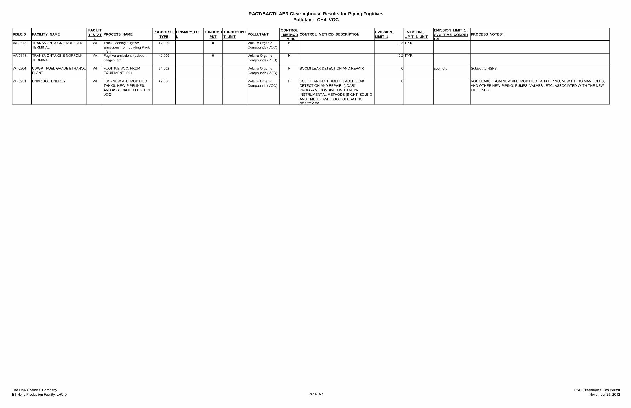
RACT/BACT/LAER Clearinghouse Results for Piping FugitivesPollutant: CH4, VOC
The Dow Chemical CompanyEthylene Production Facility, LHC-9 Page D-7
PSD Greenhouse Gas PermitNovember 29, 2012
RBLCID FACILITY_NAMEFACILITY_STAT
EPROCESS_NAME PROCCESS_
TYPEPRIMARY_FUEL
THROUGH-PUT
THROUGHPUT_UNIT POLLUTANT
CONTROL_METHOD
CODECONTROL_METHOD_DESCRIPTION EMISSION_
LIMIT_1EMISSION_LIMIT_1_UNIT
EMISSION_LIMIT_1_AVG_TIME_CONDITION
PROCESS_NOTES"
VA-0313 TRANSMONTAIGNE NORFOLK TERMINAL
VA Truck Loading Fugitive Emissions from Loading Rack LR-1
42.009 0 Volatile Organic Compounds (VOC)
N 9.3 T/YR
VA-0313 TRANSMONTAIGNE NORFOLK TERMINAL
VA Fugitive emissions (valves, flanges, etc.)
42.009 0 Volatile Organic Compounds (VOC)
N 0.2 T/YR
WI-0204 UWGP - FUEL GRADE ETHANOL PLANT
WI FUGITIVE VOC, FROM EQUIPMENT, F01
64.002 Volatile Organic Compounds (VOC)
P SOCMI LEAK DETECTION AND REPAIR 0 see note Subject to NSPS
WI-0251 ENBRIDGE ENERGY WI F01 - NEW AND MODIFIED TANKS, NEW PIPELINES, AND ASSOCIATED FUGITIVE VOC
42.006 Volatile Organic Compounds (VOC)
P USE OF AN INSTRUMENT BASED LEAK DETECTION AND REPAIR (LDAR) PROGRAM, COMBINED WITH NON-INSTRUMENTAL METHODS (SIGHT, SOUND AND SMELL), AND GOOD OPERATING PRACTICES
0 VOC LEAKS FROM NEW AND MODIFIED TANK PIPING, NEW PIPING MANIFOLDS, AND OTHER NEW PIPING, PUMPS, VALVES , ETC. ASSOCIATED WITH THE NEW PIPELINES.
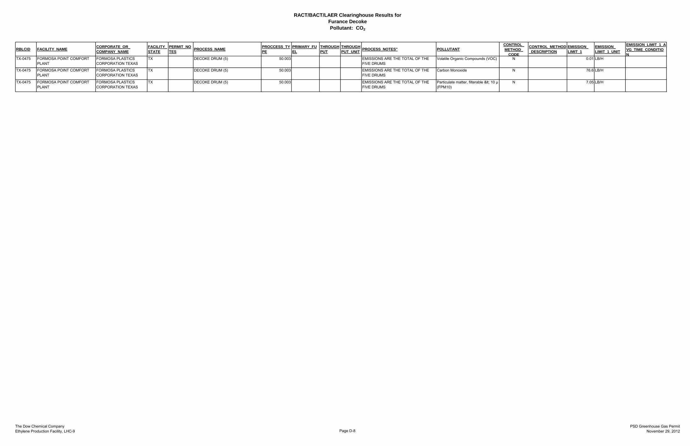
RACT/BACT/LAER Clearinghouse Results for Furance DecokePollutant: CO2
The Dow Chemical CompanyEthylene Production Facility, LHC-9 Page D-8
PSD Greenhouse Gas PermitNovember 29, 2012
RBLCID FACILITY_NAME CORPORATE_OR_COMPANY_NAME
FACILITY_STATE
PERMIT_NOTES PROCESS_NAME PROCCESS_TY
PEPRIMARY_FUEL
THROUGHPUT
THROUGHPUT_UNIT PROCESS_NOTES" POLLUTANT
CONTROL_METHOD_
CODE
CONTROL_METHOD_DESCRIPTION
EMISSION_LIMIT_1
EMISSION_LIMIT_1_UNIT
EMISSION_LIMIT_1_AVG_TIME_CONDITION
TX-0475 FORMOSA POINT COMFORT PLANT
FORMOSA PLASTICS CORPORATION TEXAS
TX DECOKE DRUM (5) 50.003 EMISSIONS ARE THE TOTAL OF THE FIVE DRUMS
Volatile Organic Compounds (VOC) N 0.01 LB/H
TX-0475 FORMOSA POINT COMFORT PLANT
FORMOSA PLASTICS CORPORATION TEXAS
TX DECOKE DRUM (5) 50.003 EMISSIONS ARE THE TOTAL OF THE FIVE DRUMS
Carbon Monoxide N 76.6 LB/H
TX-0475 FORMOSA POINT COMFORT PLANT
FORMOSA PLASTICS CORPORATION TEXAS
TX DECOKE DRUM (5) 50.003 EMISSIONS ARE THE TOTAL OF THE FIVE DRUMS
Particulate matter, filterable < 10 µ (FPM10)
N 7.05 LB/H

Appendix E Other Information
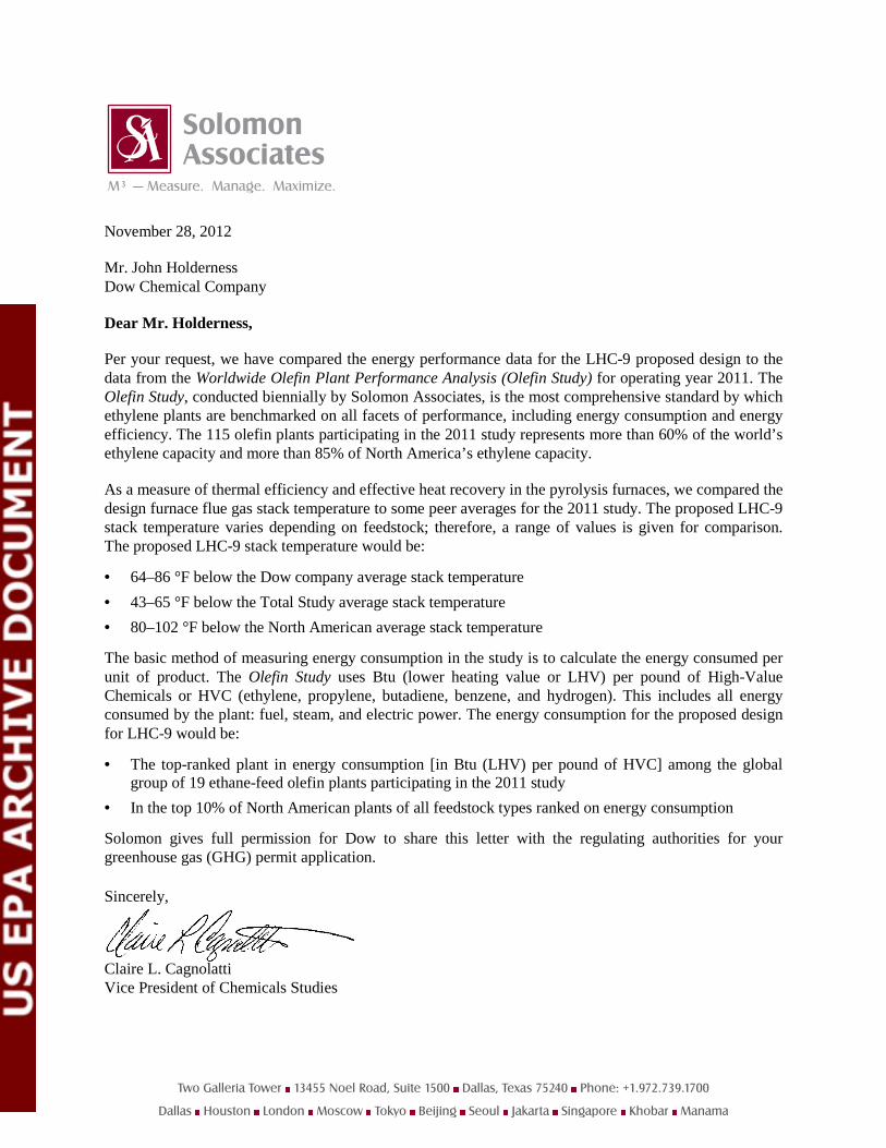
November 28, 2012
Mr. John Holderness Dow Chemical Company
Dear Mr. Holderness,
Per your request, we have compared the energy performance data for the LHC-9 proposed design to the data from the Worldwide Olefin Plant Performance Analysis (Olefin Study) for operating year 2011. The Olefin Study, conducted biennially by Solomon Associates, is the most comprehensive standard by which ethylene plants are benchmarked on all facets of performance, including energy consumption and energy efficiency. The 115 olefin plants participating in the 2011 study represents more than 60% of the world’s ethylene capacity and more than 85% of North America’s ethylene capacity.
As a measure of thermal efficiency and effective heat recovery in the pyrolysis furnaces, we compared the design furnace flue gas stack temperature to some peer averages for the 2011 study. The proposed LHC-9 stack temperature varies depending on feedstock; therefore, a range of values is given for comparison. The proposed LHC-9 stack temperature would be:
• 64–86 °F below the Dow company average stack temperature • 43–65 °F below the Total Study average stack temperature • 80–102 °F below the North American average stack temperature
The basic method of measuring energy consumption in the study is to calculate the energy consumed per unit of product. The Olefin Study uses Btu (lower heating value or LHV) per pound of High-Value Chemicals or HVC (ethylene, propylene, butadiene, benzene, and hydrogen). This includes all energy consumed by the plant: fuel, steam, and electric power. The energy consumption for the proposed design for LHC-9 would be:
• The top-ranked plant in energy consumption [in Btu (LHV) per pound of HVC] among the global group of 19 ethane-feed olefin plants participating in the 2011 study
• In the top 10% of North American plants of all feedstock types ranked on energy consumption
Solomon gives full permission for Dow to share this letter with the regulating authorities for your greenhouse gas (GHG) permit application.
Sincerely,
Claire L. Cagnolatti Vice President of Chemicals Studies
Two Galleria Tower 13455 Noel Road, Suite 1500 Dallas, Texas 75240 Phone: +1.972.739.1700
Dallas Houston London Moscow Tokyo Beijing Seoul Jakarta Singapore Khobar Manama


![Date: 20170419 Chemical Company and... · Page: 3 I. Overview [1] In these reasons, I refer to the plaintiffs Dow Chemical Company, Dow Global Technologies Inc and Dow Chemical Canada](https://img.pdfslide.us/doc/110x75/5b6414c47f8b9af5448ccff3/date-chemical-company-and-page-3-i-overview-1-in-these-reasons-i-refer.jpg)