Embed Size (px)
Citation preview

Order toll-free in the U.S.: Call 877-877-BBOX (outside U.S. call 724-746-5500)FREE technical support 24 hours a day, 7 days a week: Call 724-746-5500 or fax 724-746-0746Mailing address: Black Box Corporation, 1000 Park Drive, Lawrence, PA 15055-1018Web site: www.blackbox.com • E-mail: [email protected]
CUSTOMER SUPPORT
INFORMATION
AUGUST 1998PCW22A-R3PCW22C-R4
Protocol ConverterA/S-2G
TXD RXD RTS CTS DTR DSR CDA CDB TXD RXD RTS CTS DTR DSR TXC RXC PWR
A/S-2G
PORT A
PORT B

FCC STATEMENT
1
FEDERAL COMMUNICATIONS COMMISSIONAND
INDUSTRY CANADARADIO FREQUENCY INTERFERENCE STATEMENTS
This equipment generates, uses, and can radiate radio frequency energy and if not installed and usedproperly, that is, in strict accordance with the manufacturer’s instructions, may cause interference to radiocommunication. It has been tested and found to comply with the limits for a Class A computing device inaccordance with the specifications in Subpart J of Part 15 of FCC rules, which are designed to providereasonable protection against such interference when the equipment is operated in a commercialenvironment. Operation of this equipment in a residential area is likely to cause interference, in which case the user at his own expense will be required to take whatever measures may be necessary to correct the interference.
Changes or modifications not expressly approved by the party responsible for compliance could void the user’sauthority to operate the equipment.
This digital apparatus does not exceed the Class A limits for radio noise emission from digital apparatus set out in the RadioInterference Regulation of Industry Canada.
Le présent appareil numérique n’émet pas de bruits radioélectriques dépassant les limites applicables aux appareils numériquesde la classe A prescrites dans le Règlement sur le brouillage radioélectrique publié par Industrie Canada.
TRADEMARKS USED IN THIS MANUAL
Any trademarks mentioned in this manual are acknowledged to be the property of the trademark owners.

PROTOCOL CONVERTER A/S-2G
2
INSTRUCCIONES DE SEGURIDAD (Normas Oficiales Mexicanas Electrical Safety Statement)1. Todas las instrucciones de seguridad y operación deberán ser leídas antes de que el aparato eléctrico sea operado.
2. Las instrucciones de seguridad y operación deberán ser guardadas para referencia futura.
3. Todas las advertencias en el aparato eléctrico y en sus instrucciones de operación deben ser respetadas.
4. Todas las instrucciones de operación y uso deben ser seguidas.
5. El aparato eléctrico no deberá ser usado cerca del agua—por ejemplo, cerca de la tina de baño, lavabo, sótanomojado o cerca de una alberca, etc..
6. El aparato eléctrico debe ser usado únicamente con carritos o pedestales que sean recomendados por el fabricante.
7. El aparato eléctrico debe ser montado a la pared o al techo sólo como sea recomendado por el fabricante.
8. Servicio—El usuario no debe intentar dar servicio al equipo eléctrico más allá a lo descrito en las instrucciones deoperación. Todo otro servicio deberá ser referido a personal de servicio calificado.
9. El aparato eléctrico debe ser situado de tal manera que su posición no interfiera su uso. La colocación del aparatoeléctrico sobre una cama, sofá, alfombra o superficie similar puede bloquea la ventilación, no se debe colocar enlibreros o gabinetes que impidan el flujo de aire por los orificios de ventilación.
10. El equipo eléctrico deber ser situado fuera del alcance de fuentes de calor como radiadores, registros de calor, estufasu otros aparatos (incluyendo amplificadores) que producen calor.
11. El aparato eléctrico deberá ser connectado a una fuente de poder sólo del tipo descrito en el instructivo deoperación, o como se indique en el aparato.
12. Precaución debe ser tomada de tal manera que la tierra fisica y la polarización del equipo no sea eliminada.
13. Los cables de la fuente de poder deben ser guiados de tal manera que no sean pisados ni pellizcados por objetoscolocados sobre o contra ellos, poniendo particular atención a los contactos y receptáculos donde salen del aparato.
14. El equipo eléctrico debe ser limpiado únicamente de acuerdo a las recomendaciones del fabricante.
15. En caso de existir, una antena externa deberá ser localizada lejos de las lineas de energia.
16. El cable de corriente deberá ser desconectado del cuando el equipo no sea usado por un largo periodo de tiempo.
17. Cuidado debe ser tomado de tal manera que objectos liquidos no sean derramados sobre la cubierta u orificios deventilación.
18. Servicio por personal calificado deberá ser provisto cuando:
A: El cable de poder o el contacto ha sido dañado; u
B: Objectos han caído o líquido ha sido derramado dentro del aparato; o
C: El aparato ha sido expuesto a la lluvia; o
D: El aparato parece no operar normalmente o muestra un cambio en su desempeño; o
E: El aparato ha sido tirado o su cubierta ha sido dañada.

TABLE OF CONTENTS
3
Table of Contents1.0 Specifications .......................................................................................................................................5
2.0 Introduction.........................................................................................................................................6
3.0 Installation ...........................................................................................................................................73.1 Unpacking and Inspection ........................................................................................................73.2 Data Flow Control ......................................................................................................................7
3.2.1 SW3 ...............................................................................................................................73.2.2 SW2 ...............................................................................................................................83.2.3 Self-Diagnostics.............................................................................................................93.2.4 Reconfigure Switch Mode............................................................................................93.2.5 RS-232 Pass-through Options ....................................................................................103.2.6 Reset Options .............................................................................................................10
3.3 Preparing A/S-2G for Connection to an Asynchronous Device............................................103.3.1 Data Terminal Ready (DTR) Signal Options ...........................................................103.3.2 Clear to Send (CTS) Signal Options.........................................................................113.3.3 Baud Rate Options .....................................................................................................113.3.4 Modem or Direct-to-Terminal Connection ..............................................................113.3.5 Carrier Options ..........................................................................................................123.3.6 Cable Requirement ....................................................................................................12
3.4 Preparing the A/S-2G for Connection to a Synchronous Device .........................................123.4.1 Data Terminal Ready (DTR) Signal Options ...........................................................123.4.2 Clear to Send (CTS) Signal Options.........................................................................123.4.3 Baud Rate Options .....................................................................................................133.4.4 Modem or Direct-to-Terminal Connection ..............................................................133.4.5 External or Internal Clocking Option ......................................................................133.4.6 Carrier Options ..........................................................................................................133.4.7 Cable Requirement ....................................................................................................133.4.8 Command Pass-Thru..................................................................................................14
4.0 Operation...........................................................................................................................................154.1 Asynchronous Device to Synchronous Device........................................................................15
4.1.1 Line Control ...............................................................................................................154.1.2 Asynchronous Input Data Format.............................................................................154.1.3 Data Conversion.........................................................................................................154.1.4 Record and Block Size ...............................................................................................154.1.5 Use of Carriage Return..............................................................................................164.1.6 Flow Control ...............................................................................................................164.1.7 Presentation of Data from A/S-2G to Synchronous Device ....................................174.1.8 Verification of Data Reception ..................................................................................174.1.9 Line Turnaround .......................................................................................................17

PROTOCOL CONVERTER A/S-2G
4
4.2 Synchronous Device to Asynchronous Device........................................................................224.2.1 Line Control ...............................................................................................................224.2.2 Synchronous Input Data Format...............................................................................224.2.3 Data Conversion.........................................................................................................224.2.4 Flow Control ...............................................................................................................224.2.5 Verification of Data Reception ..................................................................................224.2.6 Line Turnaround .......................................................................................................22
5.0 Conversions and Connections ..........................................................................................................275.1 Transparency Mode of Operation...........................................................................................275.2 Installing or Replacing PROMs ...............................................................................................275.3 RS-232 Cable Chart ..................................................................................................................275.4 Code Conversions.....................................................................................................................295.5 Printed Circuit Board Layout ..................................................................................................31

CHAPTER 1: Specifications
5
1.0 SpecificationsProtocol — Asynchronous: TTY (ASCII)
Bisynchronous: 2770, 2780, 3741, and 3780 (EBCDIC)
Ports — A: AsynchronousB: Synchronous/bisynchronous
Speed — Up to 19.2 Kbps (each port independent)
Interface — RS-232 (both ports)
Connectors — (2) DB25 (female)
Flow Control — Asynchronous: X-ON/X-OFF or DTR/CTS interface lead (in DTE only)Synchronous/bisynchronous: standard BSC handshaking
Indicators — Unit Power: PWR Power (LED mounted on Port B side)Each Port: TXD Transmit Data
RXD Receive DataRTS Ready to SendCTS Clear to SendDTR Data Terminal ReadyDSR Data Send Ready
Port A only: CDA Carrier Detect Port B only: CDB Carrier Detect (LED mounted on Port A side)
TXC Transmit ClockRXC Receive Clock
Approvals — CE
Power — 115 VAC, 50/60 Hz, 63 watts (230 VAC model available upon request)
Size — 2.1"H x 11.5"W x 8.8"D (5.3 x 29.2 x 22.4 cm)
Weight — 3.5 lb. (1.6 kg)
PROTOCOL CONVERTER A/S-2G
6
2.0 IntroductionThe Model A/S-2G provides compatibility between an asynchronous, ASCII coded device and asynchronous, EBCDIC coded device. It is desirable, prior to installation, to review the followingchecklist to ensure the appropriateness of all the devices in the system for the planned application.
Synchronous (Bisynchronous) Side -
Which Protocol is being used? (2770, 2780, 3741, or 3780)
If IBM® -- is the line to be used a Bisynchronous line? Do you have the BSC Communications package?
Is machine code EBCDIC?
Asynchronous Side -
Is transmission code ASCII?
Will it operate in TTY format (start/stop, RS-232, 7 bit, and even-odd mark or space parity)?
The A/S-2G is equipped with two bidirectional RS-232C ports. These ports, labeled Port A and Port B,transfer data at up to 19.2 Kbps. Either or both ports may be connected directly to a terminal, CPU,or an appropriate modem. You configure each port’s operational parameters independently by settingDIP shunts, DIP switches, and jumpers (explained in Chapter 3.0).
Diagnostic LEDs are mounted on the front of the unit. These LEDs are labeled Port A and Port B.They are directly associated with the two ports and indicate the status of the A/S-2G at the portindicated.
The reset button on the back panel will cause the A/S-2G’s Z80A microprocessor to reinitialize (reset).

CHAPTER 3: Installation
7
3.0 Installation3.1 UNPACKING AND INSPECTIONAfter unpacking the A/S-2G, inspect it for shipping damage. Should there be any noticeable damage,save the cartons and contact the carrier who delivered the box to place a freight damage claim.
To open the A/S-2G, take out the four screws from the bottom. Lift off the cover. With the coverremoved, visually inspect for components that may have been loosened in shipment. Shippingdamage is rare, but a quick inspection is always good practice.
Leave the cover off for installation.
3.2 DATA FLOW CONTROLFor the locations of the switches and jumpers, see Figure 5-2 on page 28.
3.2.1 SW3Locate the set of 8 asynchronous switches labeled SW3 on the printed circuit board. (See Figure 5-2 on page 28.) These should be set as follows:
Switch #l ON = echo asynchronous characters — echoplex mode.
OFF = don’t echo asynchronous characters — normal mode.
Set this switch ON when the asynchronous device expects to receive an echo of its transmitted data.
NOTEThe A/S-2G always operates in half-duplex mode on the synchronous side, so this option applies only to theasynchronous device.
Switch #2 ON = echo “EOT” character.
OFF = don’t echo “EOT” character.
The last record received from the asynchronous device must be terminated with a “Control D” character. For thischaracter to echo to the asynchronous device, switch #2 must be ON. This character is echoed onlyafter the EOT sequence is sent to the synchronous device. Its echo appears as a CR LF, EOT.
NOTEAn EOT from the bisynchronous device will be displayed in the same way to the asynchronous device with thisswitch ON.
Switch #3 ON = do not include CR (carriage return) character in EBCDIC data.
OFF = include CR character in EBCDIC data
Each block sent by the asynchronous device (except the last one) must be terminated with a CR (carriage return)code. If this CR code will be included in the synchronous EBCDIC data as a new line, this switch mustbe OFF.
NOTEThe 3741 protocol is limited to a block size of 128 characters (the block size is also the record size), thus a CRmust be entered not later than each 128 characters.
PROTOCOL CONVERTER A/S-2G
8
Block size for the 2770/2780 is normally limited to 160, but block size is 400 if the 2770/2780 has theMultiple Record Transmission. Block size for the 3780 is 512.
Switch #4 ON = sends CR LF (Carriage Return, Line Feed) to asynchronous device immediately aftereach logical end of block character (ETB, or ETX) is received from the synchronousside.
OFF = Normal operation
Switch #5 ON = Variable-length blocks. This switch causes the records sent by the asynchronousdevice to be blocked and treated as variable length, i.e. no spaces are used to padout the block.
OFF = All blocks are treated as fixed length, which would require blank spaces, if necessary,to complete the block size. (In 2780 multi-record blocks, an IUS character isinserted after each 80 characters counted. The final record is the only one that maybe less than the block size specified).
NOTEIt is possible that a block will have only one record if you enter a CR after each record (2780 mode).
Switch #6 ON = 3780 MODE
OFF = 2770/2780/3741 MODE
Switch #7 ON = When RAM reaches a nearly-full state, DTR (Pin 20) will be lowered. When RAMspace is available, DTR will be raised to permit transmission to resume. Port A mustbe configured as DTE (see Section 3.2.5). When CTS from the externalasynchronous device is ON, the A/S-2G can send data. When the external devicelowers CTS, the A/S-2G will not send data.
OFF = When RAM reaches a nearly-full state, an X-OFF (ASCII DC3, 13 Hex) will be issuedto the asynchronous device to prevent buffer overrun. When RAM space is available,X-ON (ASCII DCl, 11 Hex) will be sent to resume transmission. Put the CTS Ajumper to the on position (see Section 3.2.3).
Switch #8 ON = 2 Stop Bits (asynchronous side only).
OFF = 1 Stop Bit (asynchronous side only).
3.2.2 SW2Locate the switch labeled SW2 on the printed circuit board. (See Figure 5-2 on page 28.)
Switch #1 ON = Space compression on transmit (3780 Mode only).
OFF = Normal operation.
Switch #2 ON = Pass escape sequences through.
OFF = Convert escape sequences to CR LF or FF per Section 4.2.3 on page 20.
Switch #3 ON = No Asynchronous RTS except during bisynchronous receive (half-duplex onasynchronous side).
OFF = Normal Operation (full-duplex).

CHAPTER 3: Installation
9
Switch #4 ON = Self-Diagnostics Mode.
OFF = Normal Operation.
Switch #5, #6—Block Size Specification.
5 6
OFF OFF 80 Characters
OFF ON 128 Characters
ON OFF 256 Characters
ON ON 512 Characters
NOTEFor 3741, set SW3, Switch #5: OFF (Fixed length)SW2, Switch #5: OFF, and Switch #6: OFF (128 character block)
Switch #7, #8—Asynchronous Parity Specification.
7 8
OFF OFF Space Parity (always 0)
OFF ON Mark Parity (always l)
ON OFF Odd Parity
ON ON Even Parity
NOTEThe A/S-2G only recognizes a 7-bit, 1 bit parity sequence. 8-bit data, no parity is the same as 7-bit, space parity. If you have 8-bit data, no parity, set SW2, Switches #7 and #8 to the OFF position.
3.2.3 SELF-DIAGNOSTICSThere are two ways to enter the self-diagnostic mode. The first method requires that you locate SW2,switch #4 and set it to the ON position. When you press the reset switch, the A/S-2G will displaydiagnostic information (see below) on a terminal or printer connected to Port A.
The second method requires a terminal connected to Port A. When you type an ampersand (“&”)and then a pound sign (“#”), the A/S-2G will enter the Self-Diagnostics/Reconfigure Switch Menu.Press the “l” key to enter the self-diagnostics mode and the A/S-2G will display diagnostic informationon your terminal.
This is what the A/S-2G does in self-diagnostic mode:
Displays its software versionChecks the ROMChecks the RAMDisplays the state of SW3 Displays the state of SW2 Displays the state of SW1 Port A Displays the state of SW1 Port B
The information for SW3, SW2, and SW1 is listed in binary: 1=ON and 0=OFF.
PROTOCOL CONVERTER A/S-2G
10
NOTESelf-diagnostics will normally display the switches as they are set on the printed circuit board. If the switcheswere reconfigured (see Section 3.2.4), the switches will be displayed as they are set in the software.
3.2.4 RECONFIGURE SWITCH MODETo enter the Reconfigure Switch Mode, a terminal must be connected to Port A. When you type anampersand (“&”) and then a pound sign (“#”), the A/S-2G will enter the Self-Diagnostics/ReconfigureSwitch menu. Press the “2” key to enter the Reconfigure Switch Mode. The position of SW2, Switch#4 (for self-diagnostic testing) does not affect this operation.
The setting for SW3-l (SW3, switch #1) will be displayed. To select the other option for SW3-l, press“T” (must be upper case). As long as “T” is pressed, the A/S-2G will “toggle” between or among youroptions. The option will be chosen when you press “enter.” The next switch will then be displayed.After you have entered the last option, the A/S-2G will return to the main program.
NOTE: If power is interrupted, the A/S-2G will use the manual configurations of SW1, SW2, and SW3when power is restored. The switch options chosen in the Reconfigure Switch Mode must be reentered.
3.2.5 RS-232 PASS-THROUGH OPTIONS
On the A/S-2G’s printed circuit board are three sets of double pass-through jumpers: DSR, DTR,and CD. You can have any, or all, of these signals pass-thru from one port to the other without beingregulated by the A/S-2G.
The DSR double jumper is located just below C7 on the circuit board. For normal operation (A/S-2G signal control), place the jumper over the center and left posts. For pass-through, positionthe jumper over the center and right posts.
The DTR double jumper is located just below and slightly to the right of U28 on the circuit board.For normal operation (A/S-2G signal control), place the jumper over the center and left posts. For pass-through, position the jumper over the center and right posts.
The CD double jumper is located between U20 and U24 on the circuit board. For normal operation(A/S-2G signal control), place the jumper over the center and upper posts. For pass-through, positionthe jumper over the center and lower posts.
3.2.6 RESET OPTIONSYou can configure the A/S-2G to reset automat-ically on the occurrence of Ring Indicate (RI) on eitherport or the loss of Data Set Ready (DSR) on Port A and/or Port B. These jumpers are located on theupper left of the circuit board, just below U7. Any, or all, of these jumpers may be selected. All of thereset options are disabled as shipped from the factory—the jumper is over the center and right posts.To enable one of these reset options, move the appropriate jumper over the left and center posts.
3.3 PREPARING THE A/S-2G FOR CONNECTION TO AN ASYNCHRONOUS DEVICEThe asynchronous port (Port A) is designed to connect to an asynchronous modem, terminal, or CPU.Set the switches, shunts, and jumpers as described below, then plug a male RS-232 connector into theA/S-2G’s female receptacle. Sex-change adapters, connectors, and cable are available if you need them.
3.3.1 DATA TERMINAL READY (DTR) SIGNAL OPTIONS
The asynchronous port DTR option control is a jumper labeled DTR A. It is located between U23and U24 on the circuit board. (See Figure 5-2 on page 28.) Placing the jumper over ON maintains aconstant high signal on DTR. Placing this jumper to CNT allows the A/S-2G to control data flow basedon the position of SW3, Switch #7.
CHAPTER 3: Installation
11
If SW3, Switch #7 is ON, the A/S-2G will drop DTR when only 32 character spaces remain in the buffer.The A/S-2G will reassert DTR as soon as there are at least 33 character spaces available. For mostapplications, it is best to configure SW3, Switch #7 ON.
If SW3, Switch #7 is OFF, the A/S-2G does not use DTR to control the buffer. Instead, the A/S-2Gwill issue either an X-ON or X-OFF to control data flow.
3.3.2 CLEAR TO SEND (CTS) SIGNAL OPTIONSThe asynchronous port CTS option control is a jumper labeled CTS A. It is located between U18 andU22 on the circuit board. (See Figure 5-2 on page 28.) Placing the jumper over ON maintains aconstant high signal on CTS. Placing this jumper to CNT allows the A/S-2G to control data flow.When CTS is dropped by the device connected to the A/S-2G’s asynchronous port, the A/S-2G will holdwhatever it has in its buffer and stop transmission until CTS is raised again. When the asynchronousport is configured as DCE (see Section 3.3.4), it is best to have the CTS A jumper positioned over ON.
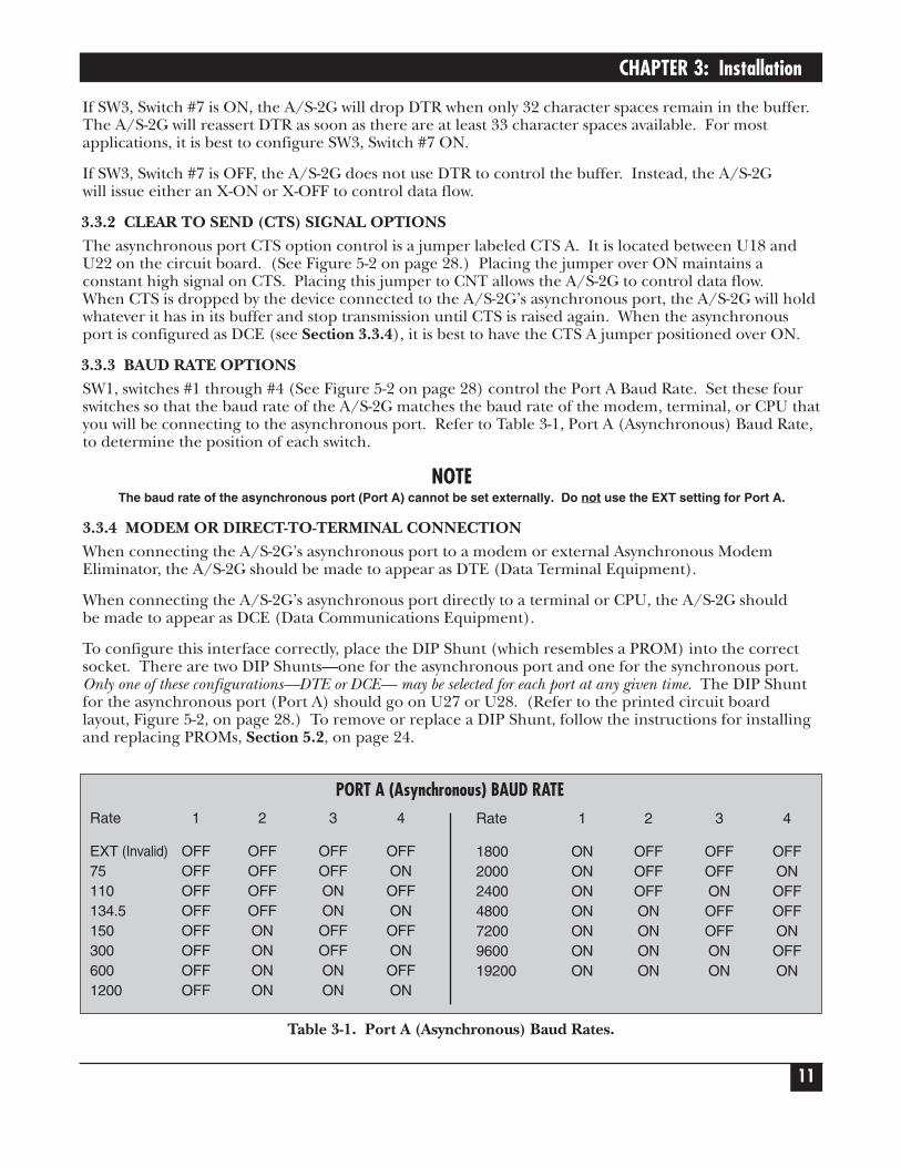
3.3.3 BAUD RATE OPTIONSSW1, switches #1 through #4 (See Figure 5-2 on page 28) control the Port A Baud Rate. Set these fourswitches so that the baud rate of the A/S-2G matches the baud rate of the modem, terminal, or CPU thatyou will be connecting to the asynchronous port. Refer to Table 3-1, Port A (Asynchronous) Baud Rate,to determine the position of each switch.
NOTEThe baud rate of the asynchronous port (Port A) cannot be set externally. Do not use the EXT setting for Port A.
3.3.4 MODEM OR DIRECT-TO-TERMINAL CONNECTION When connecting the A/S-2G’s asynchronous port to a modem or external Asynchronous ModemEliminator, the A/S-2G should be made to appear as DTE (Data Terminal Equipment).
When connecting the A/S-2G’s asynchronous port directly to a terminal or CPU, the A/S-2G shouldbe made to appear as DCE (Data Communications Equipment).
To configure this interface correctly, place the DIP Shunt (which resembles a PROM) into the correctsocket. There are two DIP Shunts—one for the asynchronous port and one for the synchronous port.Only one of these configurations—DTE or DCE— may be selected for each port at any given time. The DIP Shuntfor the asynchronous port (Port A) should go on U27 or U28. (Refer to the printed circuit boardlayout, Figure 5-2, on page 28.) To remove or replace a DIP Shunt, follow the instructions for installingand replacing PROMs, Section 5.2, on page 24.
Rate 1 2 3 4
EXT (Invalid) OFF OFF OFF OFF75 OFF OFF OFF ON110 OFF OFF ON OFF134.5 OFF OFF ON ON150 OFF ON OFF OFF300 OFF ON OFF ON600 OFF ON ON OFF1200 OFF ON ON ON
Rate 1 2 3 4
1800 ON OFF OFF OFF2000 ON OFF OFF ON2400 ON OFF ON OFF4800 ON ON OFF OFF7200 ON ON OFF ON9600 ON ON ON OFF19200 ON ON ON ON
PORT A (Asynchronous) BAUD RATE
Table 3-1. Port A (Asynchronous) Baud Rates.
PROTOCOL CONVERTER A/S-2G
12
3.3.5 CARRIER OPTIONSIf the carrier detect signal is to be driven by the A/S-2G configuration (DCE), the jumper labeled CAR AENB must be installed. CAR A ENB is located below U20. Refer to the printed circuit board, Figure 5-2,on page 28.
The carrier control jumper, CARR A, in between U18 and U19 on the circuit board (See Figure 5-2 onpage 28) should be set as follows:
(a) continuous carrier—place the jumper over the ON position.
(b) switched carrier equal to the RTS signal from the A/S-2G—place the jumper over the CNT position.
If the A/S-2G asynchronous port is configured as DCE, place a jumper over CAR A ENB and place theCARR A jumper over ON.
3.3.6 CABLE REQUIREMENTUse an RS-232 cable which is pinned straight through, i.e. 1 to 1, 2 to 2, 3 to 3, etc., to connect the A/S-2G’s asynchronous port to the modem, terminal, or CPU. Leads 1 through 8 and 20 are required (seeSection 5.3 on page 25).
3.4 PREPARING THE A/S-2G FOR CONNECTION TO A SYNCHRONOUS DEVICE The synchronous port (Port B) is designed to connect to a synchronous modem, modem eliminator, orterminal. Set the switches, shunts, and jumpers as described below, then plug a male RS-232 connectorinto the A/S-2G’s female receptacle. Sex-change adapters, connectors, and cable are available if youneed them.
3.4.1 DATA TERMINAL READY (DTR) SIGNAL OPTIONSThe synchronous port DTR option control is a jumper labeled DTR B. It is just under U26 on thecircuit board. (See Figure 5-2 on page 28.) Placing the jumper over ON maintains a constant highsignal on DTR. When this jumper is placed over CNT, the A/S-2G will drop DTR during a reset orafter receipt of a DLE EOT sequence from either the synchronous or the asynchronous port.For most installations, position the jumper over ON.
3.4.2 CLEAR TO SEND (CTS) SIGNAL OPTIONSThe synchronous port CTS option control is a jumper labeled CTS B. It is located between U21 andU25 on the circuit board. (See Figure 5-2 on page 28.) Placing the jumper over ON maintains aconstant high signal on CTS. When this jumper is placed over CNT, the A/S-2G will raise RTS when
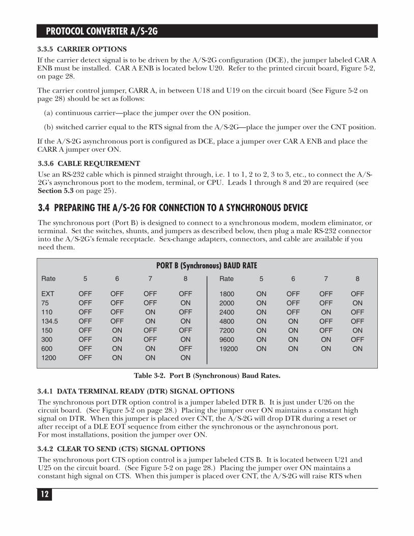
Rate 5 6 7 8
EXT OFF OFF OFF OFF75 OFF OFF OFF ON110 OFF OFF ON OFF134.5 OFF OFF ON ON150 OFF ON OFF OFF300 OFF ON OFF ON600 OFF ON ON OFF1200 OFF ON ON ON
Rate 5 6 7 8
1800 ON OFF OFF OFF2000 ON OFF OFF ON2400 ON OFF ON OFF4800 ON ON OFF OFF7200 ON ON OFF ON9600 ON ON ON OFF19200 ON ON ON ON
PORT B (Synchronous) BAUD RATE
Table 3-2. Port B (Synchronous) Baud Rates.
CHAPTER 3: Installation
13
there is data to be transmitted. Once the A/S-2G receives CTS from the attached device, it will transmitthe data. When the synchronous port (Port B) is configured as DTE, the CTS B jumper must be placedover the CNT position. Place the CTS B jumper over the CNT position when Port B is configured asDCE.
3.4.3 BAUD RATE OPTIONSFor externally provided synchronous clocking, the baud rate for the synchronous communication lineis determined by the modem or modem eliminator. To select External Clock on Port B, all switches forPort B Baud Rate (SW1, Switches #5 through #8) must be in the OFF position.
When Transmit and Receive Clock are optioned for INTERNAL, set the four switches so that the baudrate of the A/S-2G matches the baud rate of the external synchronous device. Refer to Table 3-2, Port B (Synchronous) Baud Rates, to determine the position of each switch.
3.4.4 MODEM OR DIRECT-TO-TERMINAL CONNECTIONWhen connecting the A/S-2G’s synchronous port to a modem or external Synchronous ModemEliminator, the A/S-2G should be made to appear as DTE (Data Terminal Equipment).
When connecting the A/S-2G’s synchronous port directly to a terminal or CPU, the A/S-2G shouldbe made to appear as DCE (Data Communications Equipment).
To configure this interface correctly, place the DIP Shunt (which resembles a PROM) into the correctsocket. There are two DIP Shunts—one for the asynchronous port and one for the synchronous port.Only one of these configurations—DTE or DCE— may be selected for each port at any given time. The DIP Shuntfor the synchronous port (Port B) should go on U29 or U30. Refer to the circuit board layout (Figure 5-2 on page 28). To remove or replace a DIP Shunt, follow the instructions for installing and replacingPROMs, Section 5.2, on page 24.
3.4.5 EXTERNAL OR INTERNAL CLOCKING OPTIONThe Receive and Transmit Clock options are controlled by two EXT B jumpers and two SME B jumpers.The EXT B jumpers are located near U25. The SME B jumpers are located just below U28.(Refer to the printed circuit board, Figure 5-2, on page 28.) The Receive and Transmit Clockjumpers must be selected to agree with the synchronous port DIP Shunt configuration as DTE or DCE.
When the synchronous port has been configured as DTE, Transmit and Receive Clock must be optionedfor EXTERNAL. Install both EXT B jumpers. Remove both SME B jumpers. Port B Baud Rate Switches(SW1, Switches #5 to #8) must all be in the OFF position.
When the synchronous port has been configured as DCE, Transmit and Receive Clock must be optionedfor INTERNAL. Remove both EXT B jumpers. Install both SME B jumpers. Port B Baud Rate switches(SW1, Switches #5 to #8) must then be set to match the synchronous baud rate of your external device.
3.4.6 CARRIER OPTIONSIf the Carrier Detect signal is to be driven by the A/S-2G configuration (DCE), the jumper labeled CARB ENB must be installed. CAR B ENB is located next to U19. Refer to the printed circuit board, Figure5-2, on page 28.
The carrier control jumper, CARR B, is located in between U18 and U19 on the circuit board (SeeFigure 5-2 on page 28). For most applications, the jumper should be placed over the CNT position.
3.4.7 CABLE REQUIREMENTUse an RS-232 cable which is pinned straight through, i.e. 1 to 1, 2 to 2, 3 to 3, etc., to connect the A/S-2G’s synchronous port to a modem, modem eliminator, or terminal. Leads 1 through 8, 15, 17, 20,and 22 are required (see Section 5.3 on page 25).

PROTOCOL CONVERTER A/S-2G
14
3.4.8 COMMAND PASS-THRUTo use the command pass-thru feature, the command must be preceded by &% and terminated by &%.
Example: &%-Command-&%
Commands consist of character pairs. Each pair must represent a valid Hexidecimal value (i.e. zerothrough 9 or A through F). Example: To send an escape sequence to an attached ASCII device, such as“ESC A,” the following EBCDIC string must be sent to the A/S-2G: &%lB41&%.

CHAPTER 4: Operation
4.0 OperationBy its nature, a protocol converter must operate differently in each direction, since it is communicatingwith separate devices. Therefore, its operation will be discussed separately for asynchronous tosynchronous operation and for synchronous to asynchronous.
4.1 ASYNCHRONOUS DEVICE TO SYNCHRONOUS DEVICE4.1.1 LINE CONTROLWhen the A/S-2G is initially connected to an AC power source or reset, the asynchronous device cantransmit data.
When the synchronous side has control of the line, a turnaround cannot occur until an “End ofTransmission” character has been entered from the controlling device. This character will be an EOT(EBCDIC 37 Hex) on the synchronous side.
4.1.2 ASYNCHRONOUS INPUT DATA FORMATThe asynchronous side of the A/S-2G is programmed to accept asynchronous data within the followingparameters:
1 start bit 7 data bits 1 parity bit (any parity is accepted, but ignored. Parity is user-selectable by SW2, Switches #7 and #8.) 1 or 2 stop bits (user-selectable with SW3, Switch #8)Half or full duplex (user-selectable with SW2, Switch #3)75 to 9600 bps (user-selectable by SW1, Switches #1 through #4)ASCII code
4.1.3 DATA CONVERSIONThe A/S-2G converts Asynchronous ASCII data byte-for-byte to EBCDIC equivalents, blocks itappropriately and wraps it in the applicable protocol envelope. The only characters not converted byte-for-byte are listed in Tables 4-1 and 4-2.
4.1.4 RECORD AND BLOCK SIZEIn preparing asynchronous data for communi-cation to a synchronous device, the A/S-2G groupscharacters according to the block size selected (SW2, Switches #5 and #6).
In accordance with 2770 and 2780 protocols, the A/S-2G adds an IUS (Hex 1F) followed by 2 blockcheck characters (which are subsequently stripped by the EBCDIC device) after each 80 characters untila CR is received. The CR signifies the end of a block. If SW3, Switch #5 is OFF, the A/S-2G will fill theblock with spaces until it reaches the block size specified by SW3, Switches 5 and 6. If SW3, Switch #5is ON, the block will end immediately after the CR.
ASCII CHARACTERS TRANSLATED TO EBCDICASCII to EBCDIC
Control D EOT (AA AA 32 32 32 32 37 FF)
1B (ASCII Hex) ESC (EBCDIC) (Hex 27)
CR (when SW3, Switch #3 is OFF) NL (New Line) (EBCDIC 15 Hex)
Table 4-1. ASCII characters translated to EBCDIC.
15

PROTOCOL CONVERTER A/S-2G
16
In 3741 protocol, each block contains only one record. If SW3, Switch #5 is OFF, the A/S-2G will fillthe block with spaces until it reaches 128 characters . If SW3, Switch #5 is ON, the block will endimmediately after CR.
NOTE: • If SW3, Switch #3 is OFF, then one character of the total count must be allotted to the CR. The CR
will be translated into EBCDIC as a NL (New Line). Thus, if block size is specified as 80 characters, 79 characters plus the CR would make a full 80 character record. Entering 80-characters and a CRwould cause 2 records to be sent: one with the 80 characters; the second with the NL character and,if SW3, Switch #5 is OFF, 79 spaces.
• When SW3, Switch #3 is ON, the A/S-2G will delete CR from the character count and send norepresentation of the CR with the EBCDIC data.
4.1.5 USE OF CARRIAGE RETURN(A) 2770/2780 MODE
Data from the asynchronous device is buffered (stored in RAM) until a CR (ASCII 0D Hex) is entered.If the A/S-2G receives asynchronous characters up to the selected block size without receiving a CRcharacter, the A/S-2G will add an IUS character and a 2-byte CRC sequence to the block.
When the A/S-2G receives a CR, the A/S-2G sends any buffered data to the synchronous device withan ETB (EBCDIC Hex 26).
The last block of asynchronous data must end with a “Control D” (ASCII Hex 04). The A/S-2G willsend the block, adding with an ETX (EBCDIC Hex 03). After receiving a positive acknowledgement,the A/S-2G sends an EOT.
(B) 3741/3780 MODE
Data from the asynchronous device is buffered until a CR (ASCII 0D Hex) is entered. When the A/S-2G receives a CR, the A/S-2G inserts an IRS (EBCDIC 1E Hex). Data will continue to accumulateuntil the selected block size is exceeded. At this point, the A/S-2G sends the full block of data.
The last block of asynchronous data must end with a “Control D” (ASCII Hex 04). The A/S-2G willsend the block, adding with an ETX (EBCDIC Hex 03). After receiving a positive acknowledgement,the A/S-2G sends an EOT.
4.1.6 FLOW CONTROL
The input buffer (RAM) is capable of storing up to 1720 characters. The asynchronous device cancontinuously send data to the A/S-2G if RAM is available and the character string contains a CR codebefore the buffer fills. (However, the maximum block size that is acceptable to the synchronous devicemust be considered.)
ASCII CHARACTERS NOT TRANSLATED TO EBCDIC
CR (Carriage Return) when SW3, Switch #3 is ON, LF (Line Feed), Control characters are not passed.
Character Hex Character HexNUL 00 ACK 06SOH 01 DLE 10STX 02 NAK 15ETX 03 SYN 16EOT 04 ETB 17ENQ 05 US 1F
Table 4-2. ASCII characters not translated to EBCDIC.

CHAPTER 4: Operation
17
If SW3, Switch #7 is OFF, the A/S-2G will send an X-OFF (ASCII DC3, 13 Hex) to the asynchronous devicewhen RAM reaches a nearly-full state. This prevents data from being lost due to a buffer overrun. WhenRAM space is available, the A/S-2G will send an X-ON (ASCII DC1, 11 Hex) to resume transmission.
Alternatively, if SW3, Switch #7 is ON, the A/S-2G will lower the DTR (Pin 20) when RAM reaches anearly-full state. When RAM space is available, the A/S-2G will again raise DTR to resume transmission.
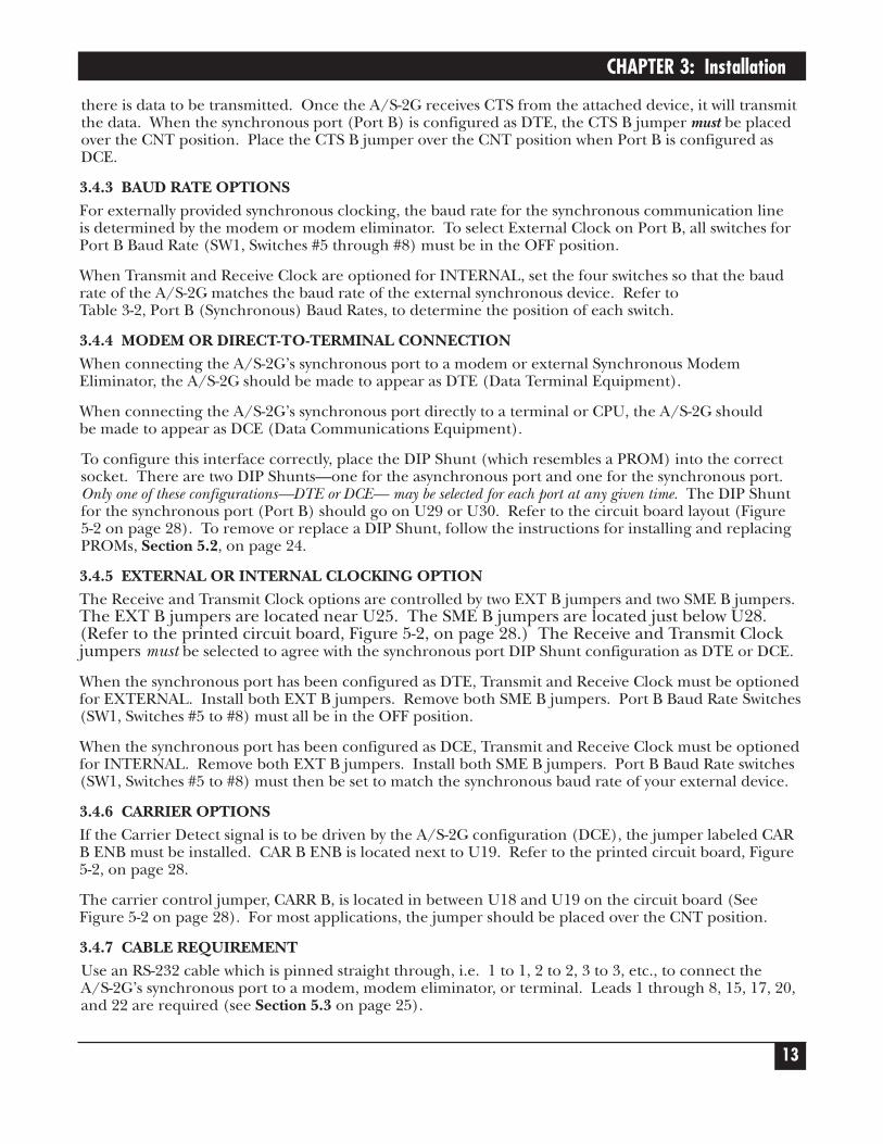
4.1.7 PRESENTATION OF DATA FROM A/S-2G TO SYNCHRONOUS DEVICEWhen an asynchronous device begins transmission to the A/S-2G and the A/S-2G has enough data fora block, the A/S-2G bids for the synchronous line and proceeds in standard bisynchronous protocol.See the Data Flow Diagrams on pages 15 through 19.
NOTE Bracketed sections indicate a selectable option. Arrows indicate the direction of data flow.
4.1.8 VERIFICATION OF DATA RECEPTIONWhen operating in full duplex mode from the asynchronous side, SW3, Switches #1 and #2 permit visualassurance of accurate and complete transmission. When SW3, Switch #1 is ON, the A/S-2G willimmediately echo back all the data it receives from the asynchronous device. When SW3, Switch #2 isON, the A/S-2G will send a CR, LF, and EOT to the asynchronous device after a complete transmissionand a line turn-around have successfully been completed.
4.1.9 LINE TURNAROUNDThe final record transmitted from the asynchronous side must be terminated with a “Control D” (ASCII04 Hex) character. This notifies the A/S-2G that the asynchronous device has completed its entry and isrelinquishing the line. After all data is sent, the A/S-2G will send an EOT sequence to the synchronousside.
Data Flow — A/S-2G to Synchronous Device
Bisynchronous Device A/S-2G Converter Asynchronous Device
Characters up to maximumBSC Block size (2770, 2780,3780) or one 128 characterrecord (3741) terminated byCR (0D Hex) = Block A ofdata received in start/stopformat
(Echo all but CR LF)
Line BidAA AA 32 32 32 32 2D FF FF
ACK 0Positive Acknowledgment—Even AA AA 32 32 32 32 1070 FF FF
ENQ
Send block A

PROTOCOL CONVERTER A/S-2G
18
Data Flow — A/S-2G to Synchronous Device
Bisynchronous Device A/S-2G Converter Asynchronous Device
*Assumes block size of 80 is selected.
IF 2270 - 2780AA AA 32 32 32 32 02 (text up to 80 characters), IF, BCC1, BCC2; etc. (lastrecord 26, BCC1, BCC2, FFFF
IF 3780AA AA 32 32 32 32 02 (text up to 80* characterswith records separated by1E, last record in block 1E,26, BCC1, BCC2, FF FF
IF 3741AA AA 32 32 32 32 02 (up to 128 characters), 26,BCC1, BCC2, FF FF
ACK 1Positive Acknowledgment—Odd AA AA 32 32 32 32 1061 FF FF
ACK 0
(Echo CR LF)
Block B of data
(Echo all but CR LF)
(Echo CR LF)
Block C of data
(Echo all but CR LF)
Block of D of data begins
Send block B

CHAPTER 4: Operation
19
Data Flow — A/S-2G to Synchronous Device
Bisynchronous Device A/S-2G Converter Asynchronous Device
ACK 1
NAKNegative AcknowledgmentAA AA 32 32 32 32 3D FF FF
ACK 0
WAKAA AA 32 32 32 32 6B FF FF
Holds up transmission whilebuffer clears DC3 (ASCII 13Hex) or drop DTR CTS oruser-specified lead
Frees up buffer space.
(Echo CR LF)
Allow resumption oftransmission DC1 (ASCII 11Hex) or raise DTR
Complete block D
Send block E
(Echo all but CR LF)
X-OFF
Send block C
X-ON
Send block D
Resend block D
Send block E
If A/S-2G buffer is nearly full when asynchronous device is transmitting:
If synchronous device has WAK capability and buffer is full:
2-second interval
If data not properly received by synchronous device orsynchronous device has no WAK capability and buffer is full:
PROTOCOL CONVERTER A/S-2G
20
Data Flow — A/S-2G to Synchronous Device
Bisynchronous Device A/S-2G Converter Asynchronous Device
WAK
ACK 1
ACK 0
AA 32 32 32 32 02 2D FF FF
NAKAA AA 32 32 32 32 3D FF FF
(Echo CR LF)
Send block F
(Echo all but CR LF)
(Echo CR LF)
Send block G,(end with EOT Hex 04)
(Echo all but CR LF EOT)
ENQ
ENQ
Send block F
TTD
Send block G
If data not yet available from asynchronous device:
Line release or turnaround:
2-second interval
WAK resets ENQ counter
Sync device buffer space available
If over 3-second interval

CHAPTER 4: Operation
21
Data Flow — A/S-2G to Synchronous Device
Bisynchronous Device A/S-2G Converter Asynchronous Device
*Assumes block size of 80 is selected.
IF 2270 - 2780AA AA 32 32 32 32 02 (text up to 80 characters), IF, BCC1, BCC2; etc. (lastrecord 03, BCC1, BCC2, FFFF
IF 3780AA AA 32 32 32 32 02 (text up to 80* characterswith records separated by1E, last record in block 1E,03, BCC1, BCC2, FF FF
IF 3741AA AA 32 32 32 32 02 (up to 128 characters), 03,BCC1, BCC2, FF FF
ACK 1
AA AA 32 32 32 32 37 FF FF
(Echo CR LF EOT)
Send EOT
Line is now idle
PROTOCOL CONVERTER A/S-2G
22
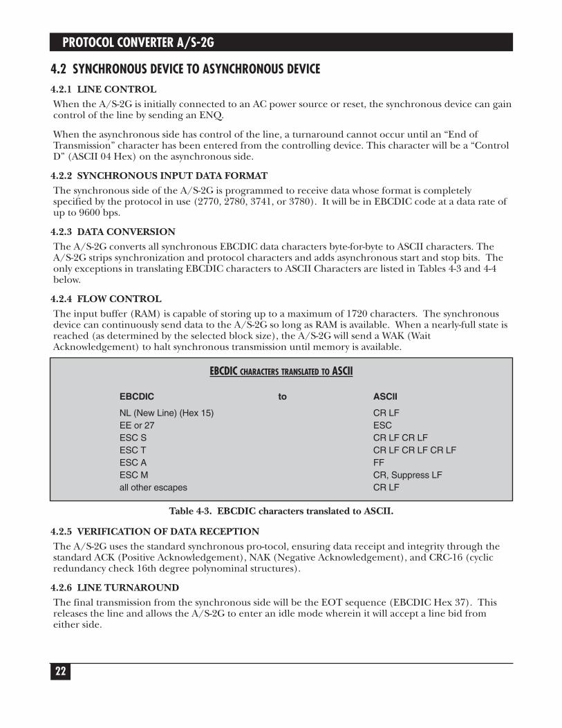
4.2 SYNCHRONOUS DEVICE TO ASYNCHRONOUS DEVICE4.2.1 LINE CONTROLWhen the A/S-2G is initially connected to an AC power source or reset, the synchronous device can gaincontrol of the line by sending an ENQ.
When the asynchronous side has control of the line, a turnaround cannot occur until an “End ofTransmission” character has been entered from the controlling device. This character will be a “ControlD” (ASCII 04 Hex) on the asynchronous side.
4.2.2 SYNCHRONOUS INPUT DATA FORMATThe synchronous side of the A/S-2G is programmed to receive data whose format is completelyspecified by the protocol in use (2770, 2780, 3741, or 3780). It will be in EBCDIC code at a data rate ofup to 9600 bps.
4.2.3 DATA CONVERSIONThe A/S-2G converts all synchronous EBCDIC data characters byte-for-byte to ASCII characters. TheA/S-2G strips synchronization and protocol characters and adds asynchronous start and stop bits. Theonly exceptions in translating EBCDIC characters to ASCII Characters are listed in Tables 4-3 and 4-4below.
4.2.4 FLOW CONTROLThe input buffer (RAM) is capable of storing up to a maximum of 1720 characters. The synchronousdevice can continuously send data to the A/S-2G so long as RAM is available. When a nearly-full state isreached (as determined by the selected block size), the A/S-2G will send a WAK (WaitAcknowledgement) to halt synchronous transmission until memory is available.
4.2.5 VERIFICATION OF DATA RECEPTIONThe A/S-2G uses the standard synchronous pro-tocol, ensuring data receipt and integrity through thestandard ACK (Positive Acknowledgement), NAK (Negative Acknowledgement), and CRC-16 (cyclicredundancy check 16th degree polynominal structures).
4.2.6 LINE TURNAROUNDThe final transmission from the synchronous side will be the EOT sequence (EBCDIC Hex 37). Thisreleases the line and allows the A/S-2G to enter an idle mode wherein it will accept a line bid fromeither side.
EBCDIC CHARACTERS TRANSLATED TO ASCII
EBCDIC to ASCII
NL (New Line) (Hex 15) CR LFEE or 27 ESCESC S CR LF CR LFESC T CR LF CR LF CR LFESC A FFESC M CR, Suppress LFall other escapes CR LF
Table 4-3. EBCDIC characters translated to ASCII.
CHAPTER 4: Operation
23
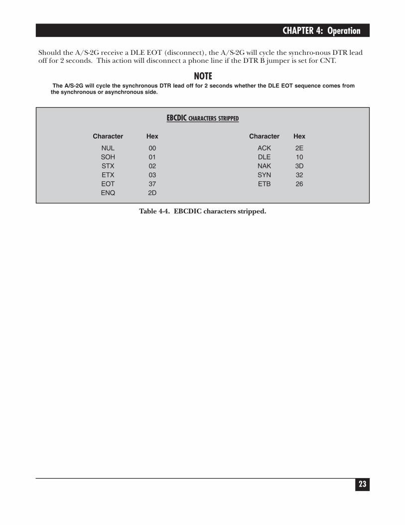
Should the A/S-2G receive a DLE EOT (disconnect), the A/S-2G will cycle the synchro-nous DTR leadoff for 2 seconds. This action will disconnect a phone line if the DTR B jumper is set for CNT.
NOTEThe A/S-2G will cycle the synchronous DTR lead off for 2 seconds whether the DLE EOT sequence comes from
the synchronous or asynchronous side.
EBCDIC CHARACTERS STRIPPED
Character Hex Character Hex
NUL 00 ACK 2ESOH 01 DLE 10STX 02 NAK 3DETX 03 SYN 32EOT 37 ETB 26ENQ 2D
Table 4-4. EBCDIC characters stripped.

PROTOCOL CONVERTER A/S-2G
24
Data Flow — A/S-2G to Asynchronous Device
Bisynchronous Device A/S-2G Converter Asynchronous DeviceENQ
Send data block A
Send data block B
ENQ
ENQ
Send data block C
Unformatted mode—successive characters(including spaces) appearone after another as sent
ACK 0
ACK 1
Send block A
WAK
WAK
Send block B
ACK 0 (whenbuffer
available)
ACK 1
Send block C
If A/S-2G buffer is nearly full when synchronous device is transmitting:
2-second interval
2-second interval
WAK resets ENQ counter withrespect to ENQ time out
CHAPTER 4: Operation
25
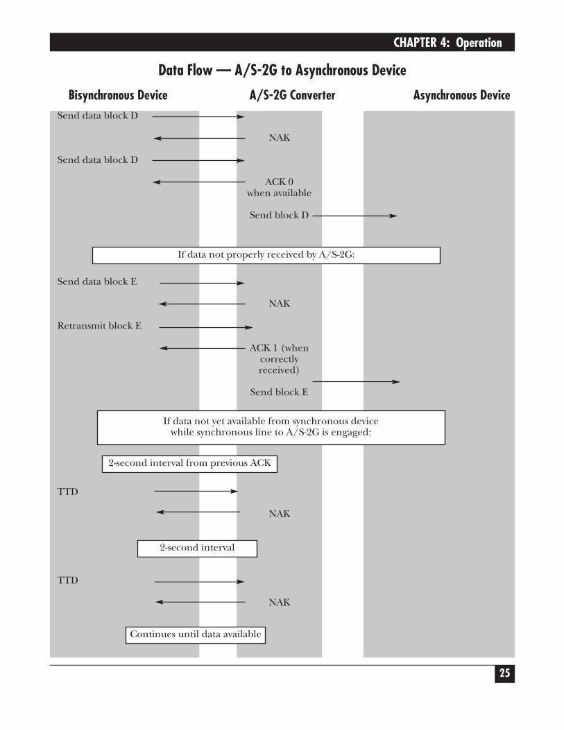
Data Flow — A/S-2G to Asynchronous Device
Bisynchronous Device A/S-2G Converter Asynchronous DeviceSend data block D
Send data block D
Send data block E
Retransmit block E
TTD
TTD
NAK
ACK 0when available
Send block D
NAK
ACK 1 (whencorrectlyreceived)
Send block E
NAK
NAK
If data not properly received by A/S-2G:
If data not yet available from synchronous device while synchronous line to A/S-2G is engaged:
2-second interval from previous ACK
2-second interval
Continues until data available
PROTOCOL CONVERTER A/S-2G
26
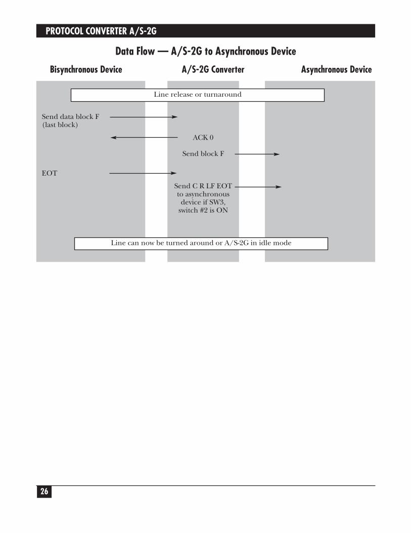
Data Flow — A/S-2G to Asynchronous Device
Bisynchronous Device A/S-2G Converter Asynchronous Device
Send data block F(last block)
EOT
ACK 0
Send block F
Send C R LF EOTto asynchronous
device if SW3,switch #2 is ON
Line can now be turned around or A/S-2G in idle mode
Line release or turnaround

CHAPTER 5: Conversions and Connections
27
5.0 Conversions and Connections5.1 TRANSPARENCY MODE OF OPERATIONWith a special transparency PROM installed, the A/S-2G will communicate with a host system in IBMbinary synchronous transparent mode. To special-order the transparency PROM, please call technicalsupport.
In transparent mode, no character translations are performed in either direction, allowing transmissionof binary file such as raw data or program object files.
In accordance with IBM specifications, each data block is bracketed with a protocol envelope consistingof a DLE STX (EBCDIC 10 Hex, 02 Hex) at the beginning and DLE ETB (EBCDIC 10 Hex, 26 Hex) atthe end. Should a DLE (10 Hex) occur within the data block, a second DLE (10 Hex) is inserted by thesending device to eliminate the possibility of a legal DLE sequence occurring by chance in the data.The A/S-2G software automatically inserts or strips the extra DLE (10 Hex) when necessary.
Transparency mode always sends fixed length blocks. Block size is selected with SW2, Switches #5 and#6. The variable/fixed switch only pertains to the last (partial) block received from the asynchronousport. The A/S-2G software detects the end of incoming asynchronous data in one of two ways:
1. Receipt of an ASCII ESC Control-D sequence (1B Hex, 04 Hex), with no other datafollowing for one second.
2 No asynchronous data received for a period of twelve seconds.
When one of these conditions occurs, the A/S-2G will transmit the last block terminated with DLE ETX.Upon acknowledgement of this last block, an EOT sequence is sent.
The transparency mode software will accept data blocks of any size (assuming no memory overflow)and will handle variable length or fixed blocks.
5.2 INSTALLING OR REPLACING PROMS1. Unplug the A/S-2G from the AC power.
2. Remove the cover of the A/S-2G.
3. To locate the PROM, see Figure 5-2 on page 28. The PROM is located on U11, between U10 andU12.
4. Using a PROM extraction tool or a small screwdriver, pry the PROM out of the socket until it is loose.Then, slide the tool or your fingers under the PROM and gently lift up. You must lift directly upwardto avoid damaging the teeth of the PROM.
5. Now insert your new PROM. It may require its pins to be pushed in a little. If so, use a table topto do this. This will ensure that the pins stay aligned.
CautionNote the orientation of the indentation on one of the prom’s short ends—it must line up with the matchingindentation on the socket into which it is inserted.
PROTOCOL CONVERTER A/S-2G
28
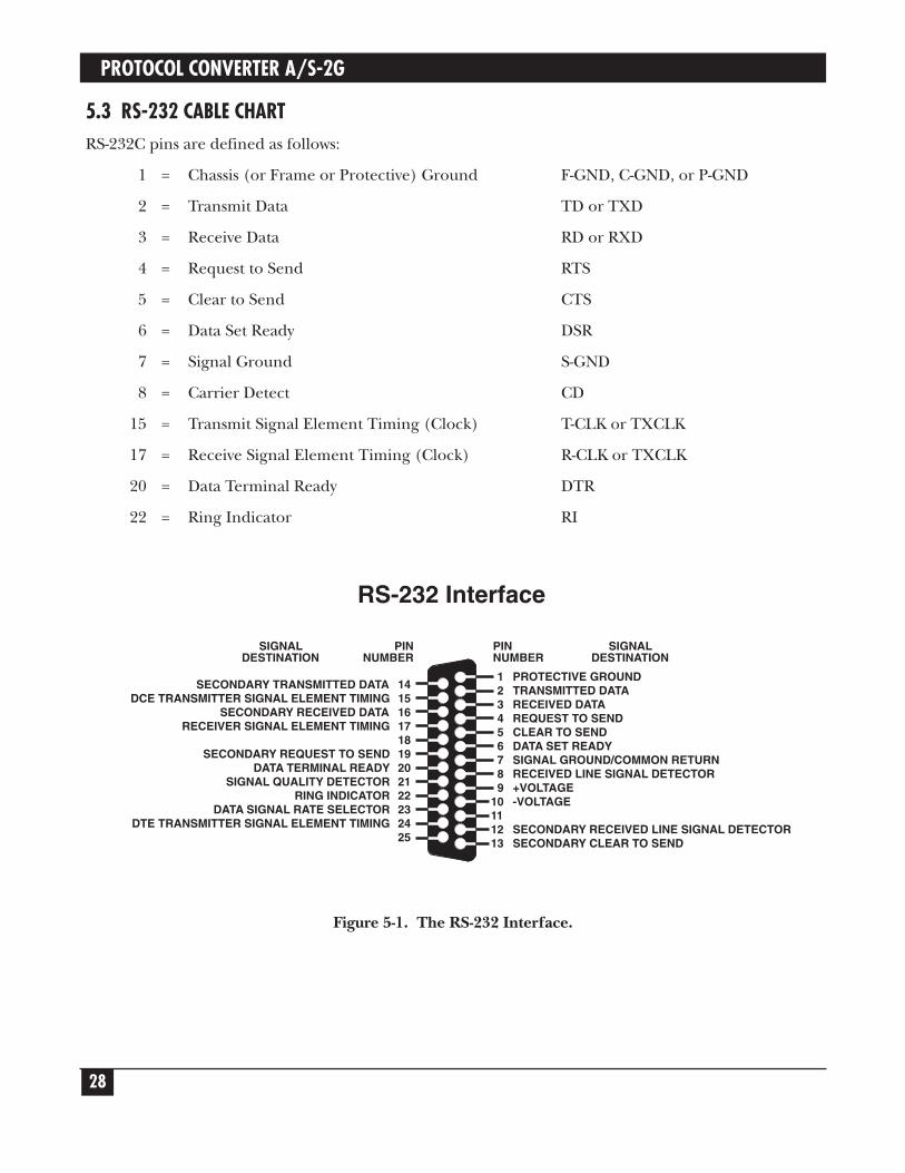
5.3 RS-232 CABLE CHARTRS-232C pins are defined as follows:
1 = Chassis (or Frame or Protective) Ground F-GND, C-GND, or P-GND
2 = Transmit Data TD or TXD
3 = Receive Data RD or RXD
4 = Request to Send RTS
5 = Clear to Send CTS
6 = Data Set Ready DSR
7 = Signal Ground S-GND
8 = Carrier Detect CD
15 = Transmit Signal Element Timing (Clock) T-CLK or TXCLK
17 = Receive Signal Element Timing (Clock) R-CLK or TXCLK
20 = Data Terminal Ready DTR
22 = Ring Indicator RI
Figure 5-1. The RS-232 Interface.
123456789
10111213
PROTECTIVE GROUNDTRANSMITTED DATARECEIVED DATAREQUEST TO SENDCLEAR TO SENDDATA SET READYSIGNAL GROUND/COMMON RETURNRECEIVED LINE SIGNAL DETECTOR+VOLTAGE-VOLTAGE
SECONDARY RECEIVED LINE SIGNAL DETECTORSECONDARY CLEAR TO SEND
141516171819202122232425
SECONDARY TRANSMITTED DATADCE TRANSMITTER SIGNAL ELEMENT TIMING
SECONDARY RECEIVED DATARECEIVER SIGNAL ELEMENT TIMING
SECONDARY REQUEST TO SENDDATA TERMINAL READY
SIGNAL QUALITY DETECTORRING INDICATOR
DATA SIGNAL RATE SELECTORDTE TRANSMITTER SIGNAL ELEMENT TIMING
PINNUMBER
PINNUMBER
SIGNALDESTINATION
SIGNALDESTINATION
RS-232 Interface

CHAPTER 5: Conversions and Connections
29
5.4 CODE CONVERSIONSThe conversions used in the standard 2770, 2780, 3741, and 3780 PROMs are shown in the followingcharts. Your PROM can be customized. Please call Technical Support if you have particular translationrequirements.
Abbreviations:
Dir. = Direction of ConversionNP = No pass (no translation in either direction)
Character
or ASCII EBCDIC
Graphic Hex Dir. Hex Comments
NUL 00 NP 00SOH 01 01STX 02 02ETX 03 03EOT 04 37ENQ 05 2DACK 06 2EBEL 07 2FBS 08 16
36 Numeric BSHT 09 05
39 Required TabLF 0A 25VT 0B OBFF 0C OC
0A Repeat WP3A Required Page End
CR 0D ODCR 15CR 06 Required CRCR 1ECR 33 Index ReturnSO OE OESI OF OF
DLE 10 10DC1 11 11DC2 12 12DC3 13 13DC4 14 3CNAK 15 3DSYN 16 NP 32
ETB (EOB) 17 NP 26CAN 18 18EM 19 19SUB 1A 3FESC 1B 27
EE1C 22
FS 1C 1CGS 1D 1D
Character
or ASCII EBCDIC
Graphic Hex Dir. Hex Comments
29RS 1E 35 IRS EBCDICUS 1F 1F
2C
SPACE 20 4041 Required SpaceE1 Numeric Space
! 21 5A EBCDIC DP" 22 7F# 23 7B$ 24 5B% 25 6C& 26 50' 27 7D( 28 4D) 29 5D* 2A 5C+ 2B 4E, 2C 6B- 2D 60
CA SYL. Hyphen. 2E 4B/ 2F 61
0 30 F01 31 F12 32 F23 33 F34 34 F45 35 F56 36 F67 37 F78 38 F89 39 F9: 3A 7A; 3B 5E
3C= 3D 7E
3E? 3F 6F

PROTOCOL CONVERTER A/S-2G
30
Character
or ASCII EBCDIC
Graphic Hex Dir. Hex Comments
@ 40 7CA 41 C1B 42 C2C 43 C3D 44 C4E 45 C5F 46 C6G 47 C7H 48 C8I 49 C9J 4A D1K 4B D2L 4C D3M 4D D4N 4E D5O 4F D6
P 50 D7Q 51 D8R 52 D9S 53 E2T 54 E3U 55 E4V 56 E5W 57 E6X 58 E7Y 59 E8Z 5A E9
5B 4A5B AD5C E05D 4F5D BD
^ 5E 5F - EBCDIC5F 6D EBCDIC underscore
“ 60 7960 14
a 61 81b 62 82c 63 83d 64 84e 65 85f 66 86g 67 87h 68 88i 69 89j 6A 91k 6B 92l 6C 93
m 6D 94n 6E 95
Character
or ASCII EBCDIC
Graphic Hex Dir. Hex Comments
o 6F 96
p 70 97q 71 98r 72 99s 73 A2t 74 A3u 75 A4v 76 A5w 77 A6x 78 A7y 79 A8z 7A A9
7B C07B 8B
| 7C 6A 1/2 EBCDIC7D D07D 9B7E A1
DEL 7F 07
SPECIAL CONVERSIONS
EBCDIC to ASCII Comments
ESC A FF
ESC M CR Suppress LF for underscore
ESC S CR LF Two CR LF sequencesCR LF
ESC T CR LF Three CR LF sequencesCR LFCR LF
Any other ESC CR LFsequence
NL CR LF
ASCII to EBCDIC Comments
CR NL This occurs only when SW3,Switch #3 is OFF.

CHAPTER 5: Conversions and Connections
UNASSIGNED EBCDIC CODE
04 2B 46 58 71 8D AB B7 CE ED08 30 47 59 72 8E AC B8 CF EF09 31 48 62 73 8F AE B9 DA FA17 34 49 63 74 90 AF BA DB FB1A 38 51 64 75 9A B0 BB DC FC
20 3B 52 65 76 9C B1 BC DD FD21 3E 53 66 77 9D B2 BE DE FE23 42 54 67 78 9E B3 BF DF FF24 43 55 68 80 9F B4 CB EA28 44 56 69 8A A0 B5 CC EB2A 45 57 70 8C AA B6 CD EC
5.5 PRINTED CIRCUIT BOARD LAYOUT
Figure 5-2. Printed Board Circuit Layout.
TX
DA
RX
DA
RT
SA
CT
SA
DT
RA
DS
RA
CD
AA
CD
B
TX
DB
RX
DB
RT
SB
CT
SB
DT
RB
DS
RB
TX
CB
RX
CB
PW
R
ON
SW
31
8
ON
SW
21
8
ON
SW
11
8
DS
R A
DS
R B
R1
U7 U8
U9
2864
EPROM
U12
U16
6116
6264
U13D
ET
EC
TC
DA
DE
TE
CT
CD
BC
AR
AE
NB
CDE
NB
CA
R B
AC
AR
RC
NT
ON
CN
TC
AR
R B
ON
CT
S A
ON
CN
TU
18
U19
U20
U17
U21
XTA
L
ONBC
TS
CN
T
EX
T
U25
U26
CN
TO
ND
TR
B
U24
U23
U22
CN
TD
TR
A
U27
U28
U29
U30
DC
E-A
DC
E-B
DT
E-A
DT
E-B
SM
EB
SM
EB
EX
T B
DT
R
DS
R PO
RT
BD
B25
PO
RT
AD
B25
OP
TSW
4R
ES
ET
P1
EA
RT
HG
ND
11V
AC
C. T
.
11V
AC
31

1000 Park Drive • Lawrence, PA 15055-1018 • 724-746-5500 • Fax 724-746-0746
© Copyright 1998. Black Box Corporation. All rights reserved.