Embed Size (px)
Citation preview
To order: Call 03-5471-8800 • Fax: 03-5471-8822Mailing address: 6-1-1 Heiwajima, Ota-ku, Tokyo, 143-6501, JapanWeb site: www.blackbox.co.jp • E-mail: [email protected]
CUSTOMER SUPPORT
INFORMATION
SEPTEMBER 2006MD1650A-JP
V.92 Dialup 2-Wire or 4-WireLeased-Line Data/Fax Modem
AT Commands Reference Guide

FCC AND IC RFI STATEMENTS/TRADEMARKS USED IN THIS MANUAL
1
FEDERAL COMMUNICATIONS COMMISSIONAND
INDUSTRY CANADARADIO FREQUENCY INTERFERENCE STATEMENTS
This equipment generates, uses, and can radiate radio-frequency energy, and if not installed and usedproperly, that is, in strict accordance with the manufacturer’s instructions, may cause interference to radiocommunication. It has been tested and found to comply with the limits for a Class A computing device inaccordance with the specifications in Subpart B of Part 15 of FCC rules, which are designed to providereasonable protection against such interference when the equipment is operated in a commercialenvironment. Operation of this equipment in a residential area is likely to cause interference, in which case the user at his own expense will be required to take whatever measures may be necessary to correct the interference.
Changes or modifications not expressly approved by the party responsible for compliance could void the user’sauthority to operate the equipment.
This digital apparatus does not exceed the Class A limits for radio noise emission from digital apparatus set out in the RadioInterference Regulation of Industry Canada.
Le présent appareil numérique n’émet pas de bruits radioélectriques dépassant les limites applicables aux appareils numériquesde la classe A prescrites dans le Règlement sur le brouillage radioélectrique publié par Industrie Canada.
TRADEMARKS USED IN THIS MANUAL
BLACK BOX and the Double Diamond logo are registered trademarks of BB Technologies, Inc.
Linux is a registered trademark of Linus Torvalds.
MNP is a registered trademark of Microcom Systems, Inc.
Windows and Windows NT are either trademarks or registered trademarks of Microsoft Corporation in theUnited States and/or other countries.
UNIX is a registered trademark of UNIX System Laboratories, Inc.
Any other trademarks mentioned in this manual are acknowledged to be the property of the trademark owners.
V.92 DIALUP 2-WIRE OR 4-WIRE LEASED-LINE DATA/FAX MODEM AT COMMANDS GUIDE
2
ContentsChapter Page
1. Overview .................................................................................................................................................................3
2. AT Commands .......................................................................................................................................................42.1 General Commands.....................................................................................................................................42.2 Escape Commands.....................................................................................................................................192.3 Modem Connection Commands ..............................................................................................................192.4 Caller ID Commands.................................................................................................................................212.5 Callback Security Commands ...................................................................................................................222.6 Data Compression Commands .................................................................................................................232.7 Error Control Commands.........................................................................................................................242.8 DTE Commands ........................................................................................................................................272.9 Modulation Command..............................................................................................................................292.10 Call Control Command.............................................................................................................................302.11 Test Command...........................................................................................................................................33
3. V.8/V.8bis Commands .........................................................................................................................................34
4. V.25bis Commands...............................................................................................................................................36
5. S-Registers.............................................................................................................................................................38
6. Result Codes.........................................................................................................................................................43
7. Setting Country/Regional Codes .......................................................................................................................517.1 Using the LCD Panel.................................................................................................................................517.2 Using the Global Wizard ...........................................................................................................................527.3 Using AT Commands ................................................................................................................................53
CHAPTER 1: Overview
3
1. OverviewAT commands are used to control your modem’s operation. Each command must be preceded by thecharacters A and T to get the modem’s attention.
AT commands can be issued only when the modem is in command mode or online command mode. Themodem is in command mode whenever it is not connected to another modem. The modem is in data modewhenever it is connected to another modem and ready to exchange data. Online command mode is atemporary state in which you can issue commands to the modem while you’re connected to another modem.
When you need to send commands to the modem at the other end of the connection, put the modem intoonline command mode from data mode. To do this, you must issue an escape sequence: Type +++ and wait forthe OK response. Then issue the hang-up command by typing ATH and pressing Enter. To return to data modefrom online command mode, type the command ATO.
To send AT commands to the modem, you must use a communications program (such as PhoneTools, which isincluded with your modem, or HyperTerminal in Windows® 95, 98, Me, XP, Windows NT® 4.0, or Windows2000). You can issue commands to the modem directly by typing them in the terminal window of thecommunications program. To issue commands indirectly, configure the operating system or communicationsprogram to send the commands automatically. Fortunately, communications programs make modems’ dailyoperation effortless by hiding the commands from the user. Most users, therefore, need to use AT commandsonly when reconfiguring the modem (for example, to turn autoanswer on or off).
The format for entering an AT command is ATXn, where X is the command and n is the value for thecommand, or command parameter. The value is always a number. If the value is zero, you can omit it from thecommand. AT&W is equivalent to AT&W0.
Most commands have a default value, which is the value that is set at the factory. Default commands areprovided with each command in Chapter 2.
You must press Enter to send the command to the modem. Any time the modem receives a command, it sendsa response known as a result code. The most common result codes are OK, ERROR, and CONNECT. For atable of valid result codes, see Chapter 6.
You can issue several commands in one line in a command string. The command string begins with AT andends when you press Enter. Spaces to separate the commands are optional; they are ignored by the commandinterpreter. The most familiar command string is the initialization string, which is used to configure themodem when it is powered on or reset, or when your communications software calls another modem.
An example of a command string is shown below. This string changes the speaker, enables V.42 errorcorrection, and enables CTS/RTS flow control.
AT M1 &E2 &K3<CR>
V.92 DIALUP 2-WIRE OR 4-WIRE LEASED-LINE DATA/FAX MODEM AT COMMANDS GUIDE
4
2. AT Commands2.1 General CommandsCommand: AT Attention CodeValues: N/ADescription: The attention code precedes all command lines except A/ and the
escape sequence.
Command: Enter KeyValues: N/ADescription: Press the Enter or Return key to execute most commands.
Command: A AnswerValues: N/ADescription: Answers an incoming call before the final ring.
Command: A/ Repeat Last CommandValues: N/ADescription: Repeats the last command string. Do not precede this command with
AT. Do not press Enter to execute.
Command: Bn Communication Standard SettingValues: n = 0 or 1Default: 1Description: B0: Selects ITU-T V.22 mode when the modem is at 300 or 1200 bps.
B1: Selects Bell 212A when the modem is at 300 or 1200 bps.
Command: Ds DialValues: s = dial string (phone number and dial modifiers)Default: NoneDescription: Dials telephone number s, where s may be up to 40 characters long and
include the following dial string modifiers.0–9 Digits 0 through 9.* The “star” digit (tone dialing only).# The “pound” digit (tone dialing only).A–D A, B, C, D tone digits. Country specific; some countries may
prohibit these digits.L Redials last number. (Must be placed immediately after ATD.)P Selects pulse dialing until a T is encountered. Affects
current/subsequent dialing.T Select tone dialing until a P is encountered. Affects current/
subsequent dialing.W Wait for a new dial tone before continuing to dial. (X2 or X4
must be selected.), Pause during dialing for time set in S-Register S8.; Return to command mode after dialing. (Place at end of dial
string.)
CHAPTER 2: AT Commands
5
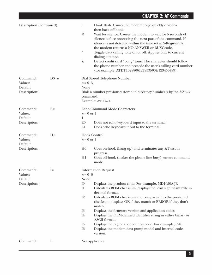
Description (continued): ! Hook flash. Causes the modem to go quickly on-hook then back off-hook.
@ Wait for silence. Causes the modem to wait for 5 seconds of silence before processing the next part of the command. If silence is not detected within the time set in S-Register S7, the modem returns a NO ANSWER or BUSY code.
^ Toggle data calling tone on or off. Applies only to current dialing attempt.
& Detect credit card “bong” tone. The character should follow the phone number and precede the user’s calling card number (for example, ATDT1028806127853500&123456789).
Command: DS=n Dial Stored Telephone NumberValues: n = 0–3Default: NoneDescription: Dials a number previously stored in directory number n by the &Zn=x
command.Example: ATDS=3.
Command: En Echo Command Mode CharactersValues: n = 0 or 1Default: 1Description: E0 Does not echo keyboard input to the terminal.
E1 Does echo keyboard input to the terminal.
Command: Hn Hook ControlValues: n = 0 or 1Default: 0Description: H0 Goes on-hook (hang up) and terminates any &T test in
progress.H1 Goes off-hook (makes the phone line busy); enters command
mode.
Command: In Information RequestValues: n = 0–6Default: NoneDescription: I0 Displays the product code. For example, MD1650A-JP.
I1 Calculates ROM checksum; displays the least significant byte in decimal format.
I2 Calculates ROM checksum and compares it to the prestoredchecksum, displays OK if they match or ERROR if they don’tmatch.
I3 Displays the firmware version and application codes.I4 Displays the OEM-defined identifier string in either binary or
ASCII format.I5 Displays the regional or country code. For example, 098.I6 Displays the modem data pump model and internal code
version.
Command: L Not applicable.
V.92 DIALUP 2-WIRE OR 4-WIRE LEASED-LINE DATA/FAX MODEM AT COMMANDS GUIDE
6
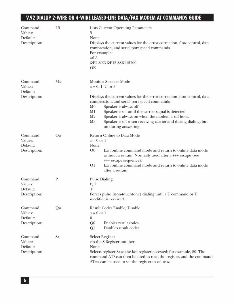
Command: L5 Lists Current Operating ParametersValues: 5Default: NoneDescription: Displays the current values for the error correction, flow control, data
compression, and serial port speed commands.For example:atL5&E2 &E3 &E15 $SB115200OK
Command: Mn Monitor Speaker ModeValues: n = 0, 1, 2, or 3Default: 1Description: Displays the current values for the error correction, flow control, data
compression, and serial port speed commands.M0 Speaker is always off.M1 Speaker is on until the carrier signal is detected.M2 Speaker is always on when the modem is off-hook.M3 Speaker is off when receiving carrier and during dialing, but
on during answering.
Command: On Return Online to Data ModeValues: n = 0 or 1Default: NoneDescription: O0 Exit online command mode and return to online data mode
without a retrain. Normally used after a +++ escape (see +++ escape sequence).
O1 Exit online command mode and return to online data mode after a retrain.
Command: P Pulse DialingValues: P, TDefault: TDescription: Forces pulse (non-touchtone) dialing until a T command or T
modifier is received.
Command: Qn Result Codes Enable/DisableValues: n = 0 or 1Default: 0Description: Q0 Enables result codes.
Q1 Disables result codes.
Command: Sr Select RegisterValues: r is the S-Register numberDefault: NoneDescription: Selects register Sr as the last register accessed; for example, S0. The
command AT? can then be used to read the register, and the commandAT=n can be used to set the register to value n.
CHAPTER 2: AT Commands
7
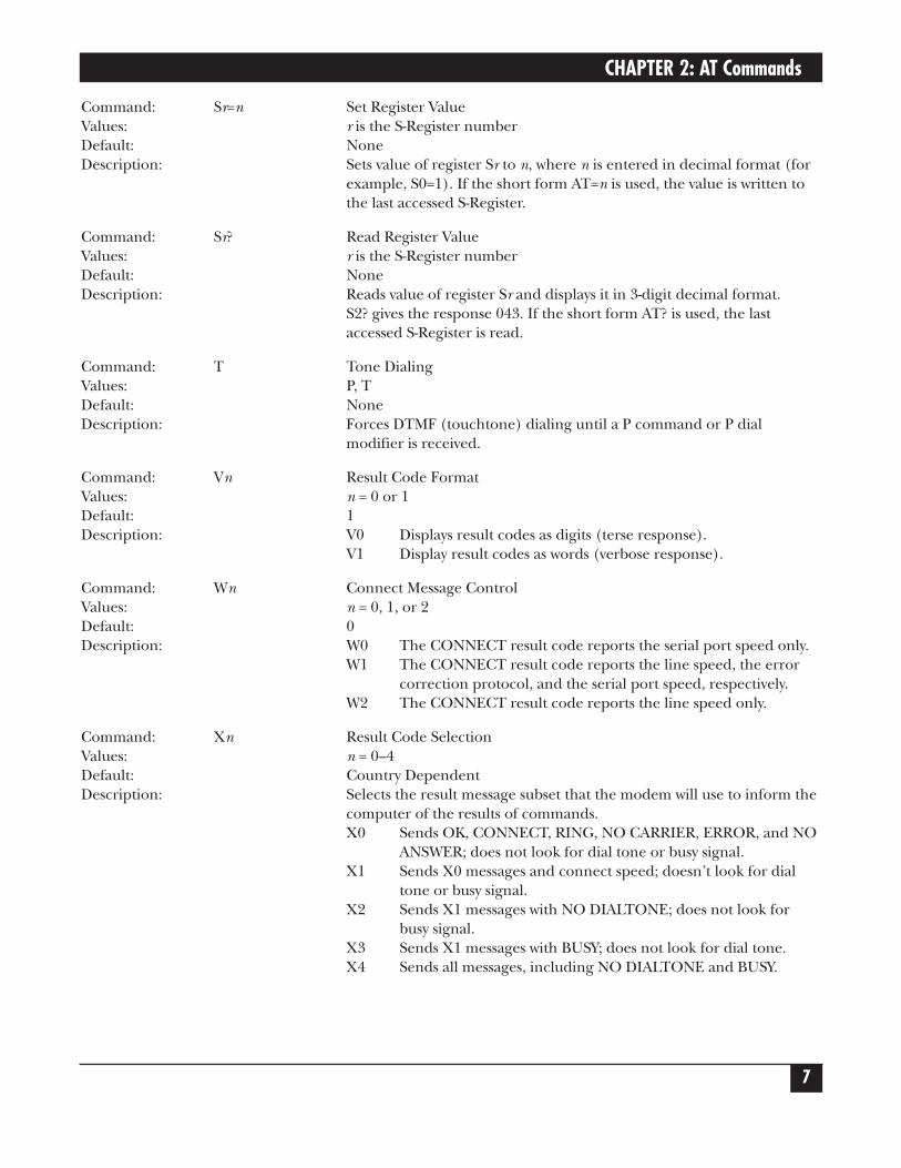
Command: Sr=n Set Register ValueValues: r is the S-Register numberDefault: NoneDescription: Sets value of register Sr to n, where n is entered in decimal format (for
example, S0=1). If the short form AT=n is used, the value is written tothe last accessed S-Register.
Command: Sr? Read Register ValueValues: r is the S-Register numberDefault: NoneDescription: Reads value of register Sr and displays it in 3-digit decimal format.
S2? gives the response 043. If the short form AT? is used, the lastaccessed S-Register is read.
Command: T Tone DialingValues: P, TDefault: NoneDescription: Forces DTMF (touchtone) dialing until a P command or P dial
modifier is received.
Command: Vn Result Code FormatValues: n = 0 or 1Default: 1Description: V0 Displays result codes as digits (terse response).
V1 Display result codes as words (verbose response).
Command: Wn Connect Message ControlValues: n = 0, 1, or 2Default: 0Description: W0 The CONNECT result code reports the serial port speed only.
W1 The CONNECT result code reports the line speed, the error correction protocol, and the serial port speed, respectively.
W2 The CONNECT result code reports the line speed only.
Command: Xn Result Code SelectionValues: n = 0–4Default: Country DependentDescription: Selects the result message subset that the modem will use to inform the
computer of the results of commands.X0 Sends OK, CONNECT, RING, NO CARRIER, ERROR, and NO
ANSWER; does not look for dial tone or busy signal.X1 Sends X0 messages and connect speed; doesn’t look for dial
tone or busy signal.X2 Sends X1 messages with NO DIALTONE; does not look for
busy signal.X3 Sends X1 messages with BUSY; does not look for dial tone.X4 Sends all messages, including NO DIALTONE and BUSY.
V.92 DIALUP 2-WIRE OR 4-WIRE LEASED-LINE DATA/FAX MODEM AT COMMANDS GUIDE
8
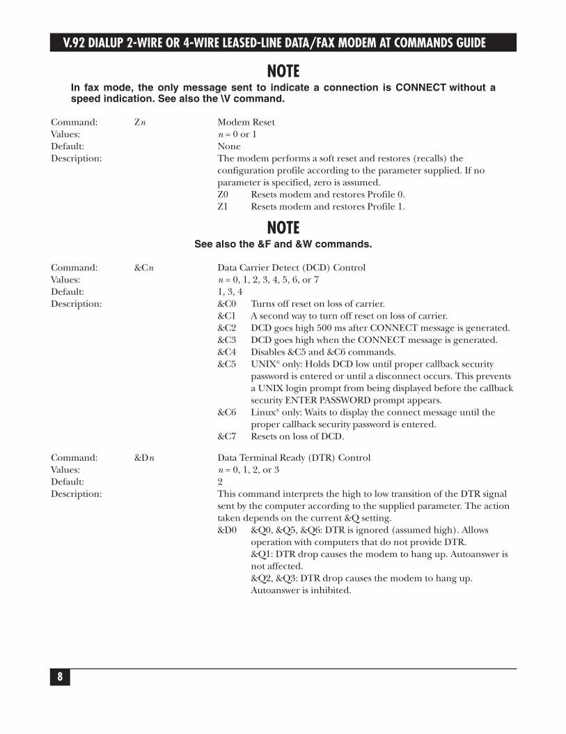
NOTEIn fax mode, the only message sent to indicate a connection is CONNECT without aspeed indication. See also the \V command.
Command: Zn Modem ResetValues: n = 0 or 1Default: NoneDescription: The modem performs a soft reset and restores (recalls) the
configuration profile according to the parameter supplied. If noparameter is specified, zero is assumed.Z0 Resets modem and restores Profile 0.Z1 Resets modem and restores Profile 1.
NOTESee also the &F and &W commands.
Command: &Cn Data Carrier Detect (DCD) ControlValues: n = 0, 1, 2, 3, 4, 5, 6, or 7Default: 1, 3, 4Description: &C0 Turns off reset on loss of carrier.
&C1 A second way to turn off reset on loss of carrier.&C2 DCD goes high 500 ms after CONNECT message is generated.&C3 DCD goes high when the CONNECT message is generated.&C4 Disables &C5 and &C6 commands.&C5 UNIX® only: Holds DCD low until proper callback security
password is entered or until a disconnect occurs. This prevents a UNIX login prompt from being displayed before the callbacksecurity ENTER PASSWORD prompt appears.
&C6 Linux® only: Waits to display the connect message until the proper callback security password is entered.
&C7 Resets on loss of DCD.
Command: &Dn Data Terminal Ready (DTR) ControlValues: n = 0, 1, 2, or 3Default: 2Description: This command interprets the high to low transition of the DTR signal
sent by the computer according to the supplied parameter. The actiontaken depends on the current &Q setting.&D0 &Q0, &Q5, &Q6: DTR is ignored (assumed high). Allows
operation with computers that do not provide DTR.&Q1: DTR drop causes the modem to hang up. Autoanswer is not affected.&Q2, &Q3: DTR drop causes the modem to hang up. Autoanswer is inhibited.
CHAPTER 2: AT Commands
9
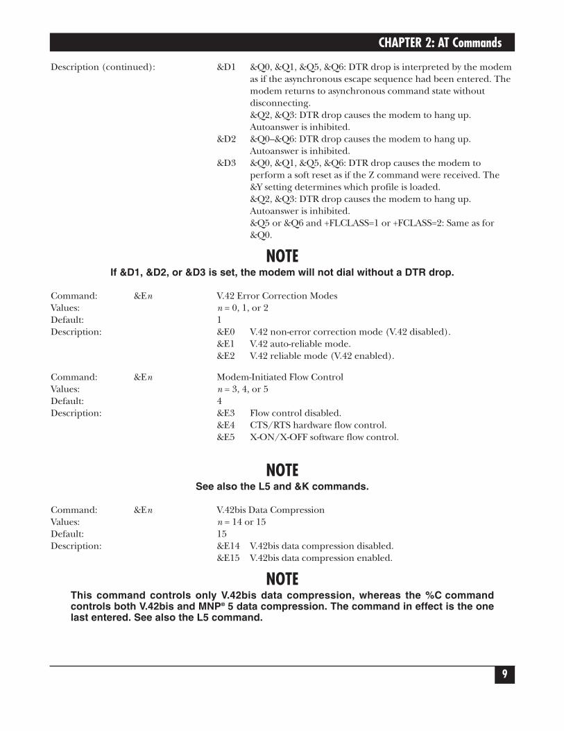
Description (continued): &D1 &Q0, &Q1, &Q5, &Q6: DTR drop is interpreted by the modem as if the asynchronous escape sequence had been entered. The modem returns to asynchronous command state without disconnecting.&Q2, &Q3: DTR drop causes the modem to hang up. Autoanswer is inhibited.
&D2 &Q0–&Q6: DTR drop causes the modem to hang up. Autoanswer is inhibited.
&D3 &Q0, &Q1, &Q5, &Q6: DTR drop causes the modem to perform a soft reset as if the Z command were received. The &Y setting determines which profile is loaded.&Q2, &Q3: DTR drop causes the modem to hang up. Autoanswer is inhibited.&Q5 or &Q6 and +FLCLASS=1 or +FCLASS=2: Same as for &Q0.
NOTEIf &D1, &D2, or &D3 is set, the modem will not dial without a DTR drop.
Command: &En V.42 Error Correction ModesValues: n = 0, 1, or 2Default: 1Description: &E0 V.42 non-error correction mode (V.42 disabled).
&E1 V.42 auto-reliable mode.&E2 V.42 reliable mode (V.42 enabled).
Command: &En Modem-Initiated Flow ControlValues: n = 3, 4, or 5Default: 4Description: &E3 Flow control disabled.
&E4 CTS/RTS hardware flow control.&E5 X-ON/X-OFF software flow control.
NOTESee also the L5 and &K commands.
Command: &En V.42bis Data CompressionValues: n = 14 or 15Default: 15Description: &E14 V.42bis data compression disabled.
&E15 V.42bis data compression enabled.
NOTEThis command controls only V.42bis data compression, whereas the %C commandcontrols both V.42bis and MNP® 5 data compression. The command in effect is the onelast entered. See also the L5 command.
V.92 DIALUP 2-WIRE OR 4-WIRE LEASED-LINE DATA/FAX MODEM AT COMMANDS GUIDE
10
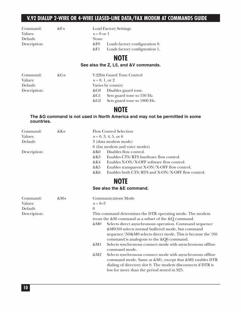
Command: &Fn Load Factory SettingsValues: n = 0 or 1Default: NoneDescription: &F0 Loads factory configuration 0.
&F1 Loads factory configuration 1.
NOTESee also the Z, L5, and &V commands.
Command: &Gn V.22bis Guard Tone ControlValues: n = 0, 1, or 2Default: Varies by countryDescription: &G0 Disables guard tone.
&G1 Sets guard tone to 550 Hz.&G2 Sets guard tone to 1800 Hz.
NOTEThe &G command is not used in North America and may not be permitted in somecountries.
Command: &Kn Flow Control SelectionValues: n = 0, 3, 4, 5, or 6Default: 3 (data modem mode)
6 (fax modem and voice modes)Description: &K0 Disables flow control.
&K3 Enables CTS/RTS hardware flow control.&K4 Enables X-ON/X-OFF software flow control.&K5 Enables transparent X-ON/X-OFF flow control.&K6 Enables both CTS/RTS and X-ON/X-OFF flow control.
NOTESee also the &E command.
Command: &Mn Communications ModeValues: n = 0–3Default: 0Description: This command determines the DTR operating mode. The modem
treats the &M command as a subset of the &Q command.&M0 Selects direct asynchronous operation. Command sequence
&M0\N0 selects normal buffered mode, but command sequence \N0&M0 selects direct mode. This is because the \N0 command is analogous to the &Q6 command.
&M1 Selects synchronous connect mode with asynchronous offline command mode.
&M2 Selects synchronous connect mode with asynchronous offline command mode. Same as &M1, except that &M2 enables DTR dialing of directory slot 0. The modem disconnects if DTR is low for more than the period stored in S25.
CHAPTER 2: AT Commands
11
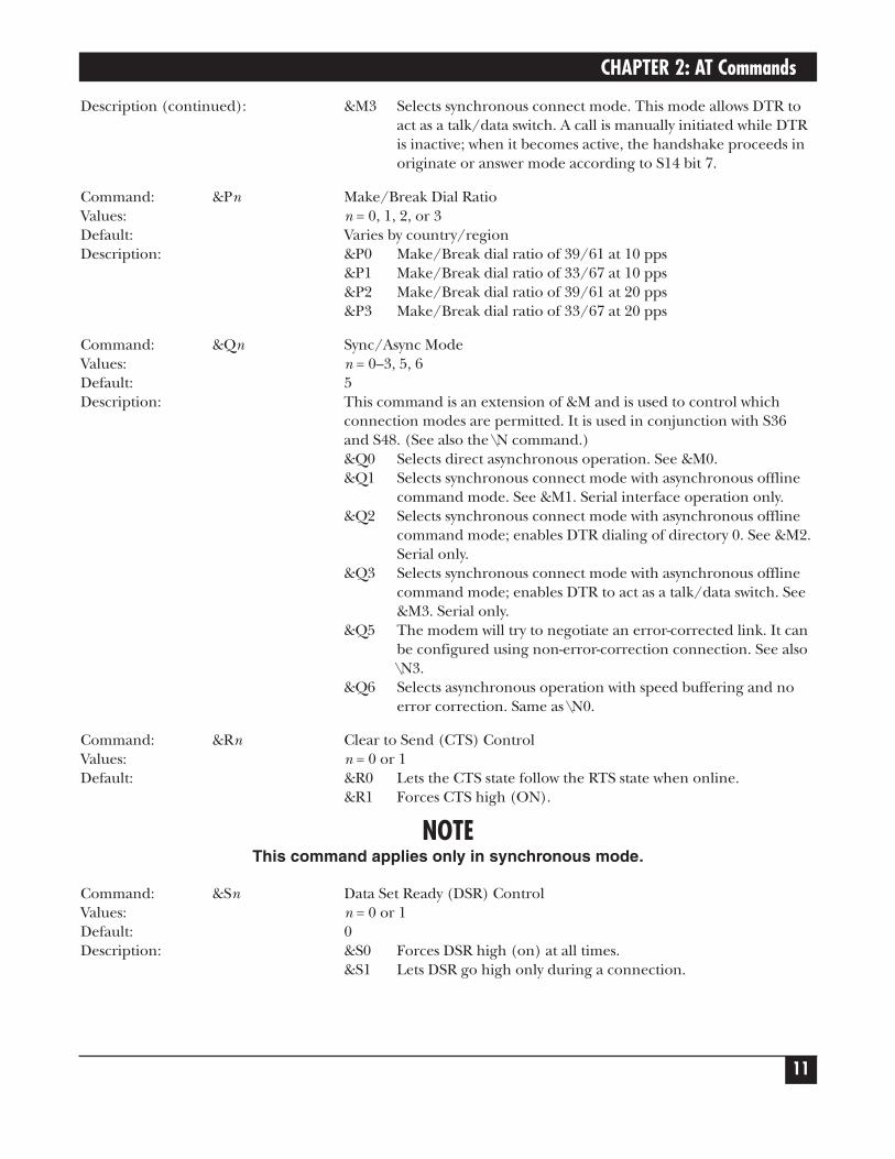
Description (continued): &M3 Selects synchronous connect mode. This mode allows DTR to act as a talk/data switch. A call is manually initiated while DTRis inactive; when it becomes active, the handshake proceeds in originate or answer mode according to S14 bit 7.
Command: &Pn Make/Break Dial RatioValues: n = 0, 1, 2, or 3Default: Varies by country/regionDescription: &P0 Make/Break dial ratio of 39/61 at 10 pps
&P1 Make/Break dial ratio of 33/67 at 10 pps&P2 Make/Break dial ratio of 39/61 at 20 pps&P3 Make/Break dial ratio of 33/67 at 20 pps
Command: &Qn Sync/Async ModeValues: n = 0–3, 5, 6Default: 5Description: This command is an extension of &M and is used to control which
connection modes are permitted. It is used in conjunction with S36and S48. (See also the \N command.)&Q0 Selects direct asynchronous operation. See &M0.&Q1 Selects synchronous connect mode with asynchronous offline
command mode. See &M1. Serial interface operation only.&Q2 Selects synchronous connect mode with asynchronous offline
command mode; enables DTR dialing of directory 0. See &M2. Serial only.
&Q3 Selects synchronous connect mode with asynchronous offline command mode; enables DTR to act as a talk/data switch. See &M3. Serial only.
&Q5 The modem will try to negotiate an error-corrected link. It can be configured using non-error-correction connection. See also \N3.
&Q6 Selects asynchronous operation with speed buffering and no error correction. Same as \N0.
Command: &Rn Clear to Send (CTS) ControlValues: n = 0 or 1Default: &R0 Lets the CTS state follow the RTS state when online.
&R1 Forces CTS high (ON).
NOTEThis command applies only in synchronous mode.
Command: &Sn Data Set Ready (DSR) ControlValues: n = 0 or 1Default: 0Description: &S0 Forces DSR high (on) at all times.
&S1 Lets DSR go high only during a connection.
V.92 DIALUP 2-WIRE OR 4-WIRE LEASED-LINE DATA/FAX MODEM AT COMMANDS GUIDE
12
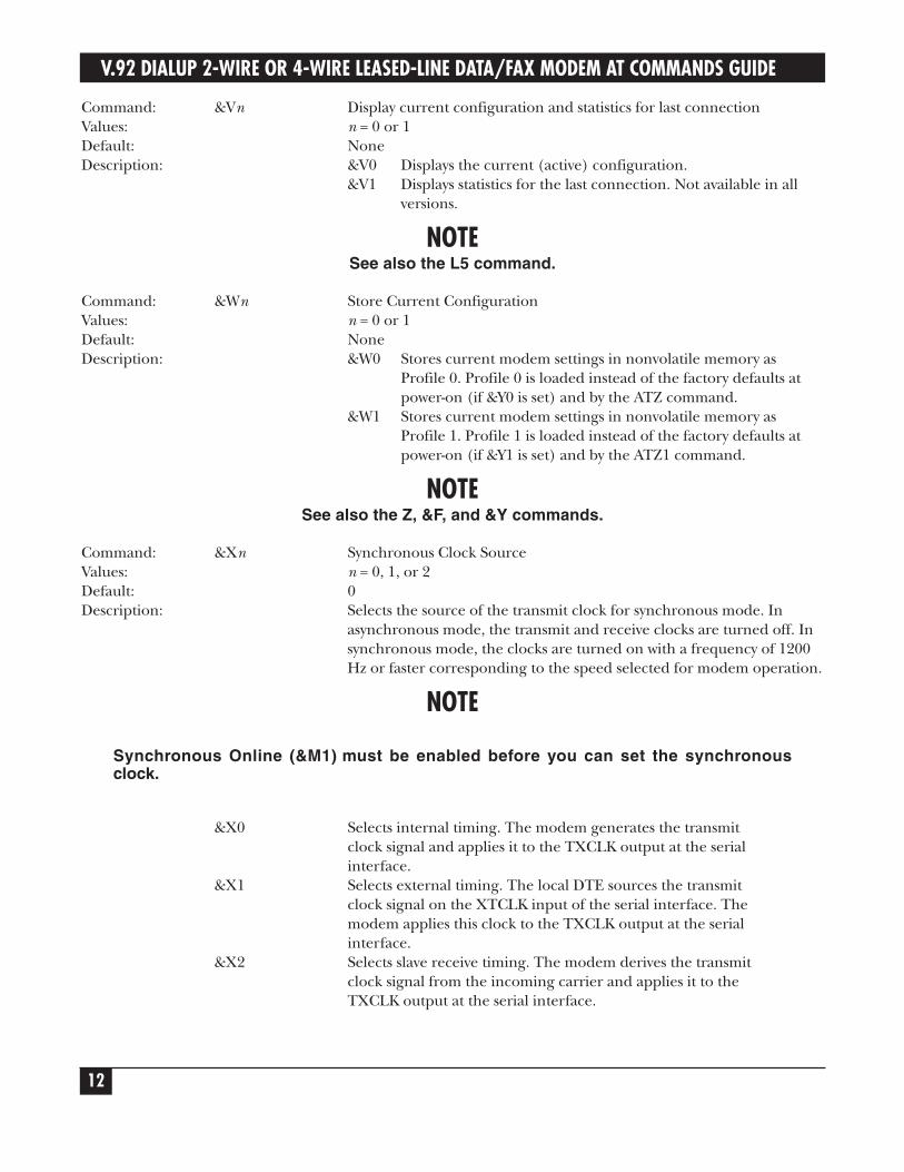
Command: &Vn Display current configuration and statistics for last connectionValues: n = 0 or 1Default: NoneDescription: &V0 Displays the current (active) configuration.
&V1 Displays statistics for the last connection. Not available in all versions.
NOTESee also the L5 command.
Command: &Wn Store Current ConfigurationValues: n = 0 or 1Default: NoneDescription: &W0 Stores current modem settings in nonvolatile memory as
Profile 0. Profile 0 is loaded instead of the factory defaults at power-on (if &Y0 is set) and by the ATZ command.
&W1 Stores current modem settings in nonvolatile memory as Profile 1. Profile 1 is loaded instead of the factory defaults at power-on (if &Y1 is set) and by the ATZ1 command.
NOTESee also the Z, &F, and &Y commands.
Command: &Xn Synchronous Clock SourceValues: n = 0, 1, or 2Default: 0Description: Selects the source of the transmit clock for synchronous mode. In
asynchronous mode, the transmit and receive clocks are turned off. Insynchronous mode, the clocks are turned on with a frequency of 1200Hz or faster corresponding to the speed selected for modem operation.
NOTE
Synchronous Online (&M1) must be enabled before you can set the synchronousclock.
&X0 Selects internal timing. The modem generates the transmit clock signal and applies it to the TXCLK output at the serial interface.
&X1 Selects external timing. The local DTE sources the transmit clock signal on the XTCLK input of the serial interface. The modem applies this clock to the TXCLK output at the serial interface.
&X2 Selects slave receive timing. The modem derives the transmit clock signal from the incoming carrier and applies it to the TXCLK output at the serial interface.
CHAPTER 2: AT Commands
13
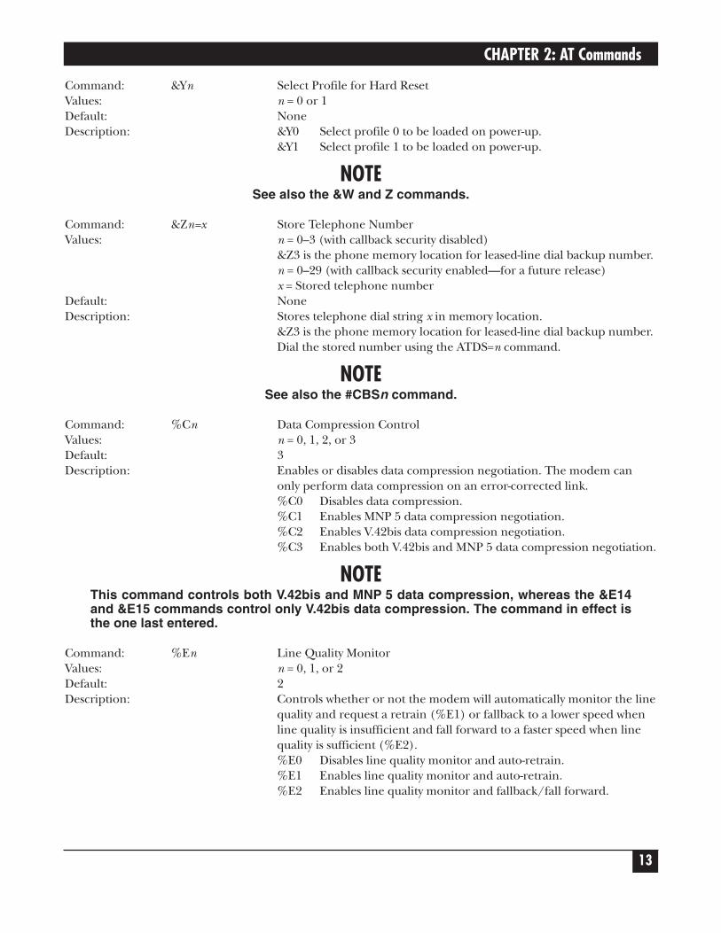
Command: &Yn Select Profile for Hard ResetValues: n = 0 or 1Default: NoneDescription: &Y0 Select profile 0 to be loaded on power-up.
&Y1 Select profile 1 to be loaded on power-up.
NOTESee also the &W and Z commands.
Command: &Zn=x Store Telephone NumberValues: n = 0–3 (with callback security disabled)
&Z3 is the phone memory location for leased-line dial backup number.n = 0–29 (with callback security enabled—for a future release)x = Stored telephone number
Default: NoneDescription: Stores telephone dial string x in memory location.
&Z3 is the phone memory location for leased-line dial backup number.Dial the stored number using the ATDS=n command.
NOTESee also the #CBSn command.
Command: %Cn Data Compression ControlValues: n = 0, 1, 2, or 3Default: 3Description: Enables or disables data compression negotiation. The modem can
only perform data compression on an error-corrected link.%C0 Disables data compression.%C1 Enables MNP 5 data compression negotiation.%C2 Enables V.42bis data compression negotiation.%C3 Enables both V.42bis and MNP 5 data compression negotiation.
NOTEThis command controls both V.42bis and MNP 5 data compression, whereas the &E14and &E15 commands control only V.42bis data compression. The command in effect isthe one last entered.
Command: %En Line Quality MonitorValues: n = 0, 1, or 2Default: 2Description: Controls whether or not the modem will automatically monitor the line
quality and request a retrain (%E1) or fallback to a lower speed whenline quality is insufficient and fall forward to a faster speed when linequality is sufficient (%E2).%E0 Disables line quality monitor and auto-retrain.%E1 Enables line quality monitor and auto-retrain.%E2 Enables line quality monitor and fallback/fall forward.
V.92 DIALUP 2-WIRE OR 4-WIRE LEASED-LINE DATA/FAX MODEM AT COMMANDS GUIDE
14
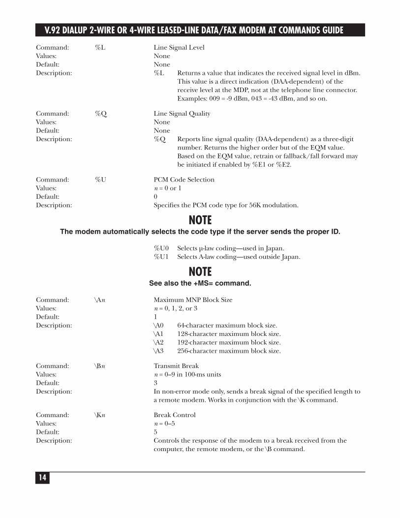
Command: %L Line Signal LevelValues: NoneDefault: NoneDescription: %L Returns a value that indicates the received signal level in dBm.
This value is a direct indication (DAA-dependent) of the receive level at the MDP, not at the telephone line connector.Examples: 009 = -9 dBm, 043 = -43 dBm, and so on.
Command: %Q Line Signal QualityValues: NoneDefault: NoneDescription: %Q Reports line signal quality (DAA-dependent) as a three-digit
number. Returns the higher order but of the EQM value. Based on the EQM value, retrain or fallback/fall forward may be initiated if enabled by %E1 or %E2.
Command: %U PCM Code SelectionValues: n = 0 or 1Default: 0Description: Specifies the PCM code type for 56K modulation.
NOTEThe modem automatically selects the code type if the server sends the proper ID.
%U0 Selects µ-law coding—used in Japan.%U1 Selects A-law coding—used outside Japan.
NOTESee also the +MS= command.
Command: \An Maximum MNP Block SizeValues: n = 0, 1, 2, or 3Default: 1Description: \A0 64-character maximum block size.
\A1 128-character maximum block size.\A2 192-character maximum block size.\A3 256-character maximum block size.
Command: \Bn Transmit BreakValues: n = 0–9 in 100-ms unitsDefault: 3Description: In non-error mode only, sends a break signal of the specified length to
a remote modem. Works in conjunction with the \K command.
Command: \Kn Break ControlValues: n = 0–5Default: 5Description: Controls the response of the modem to a break received from the
computer, the remote modem, or the \B command.
CHAPTER 2: AT Commands
15
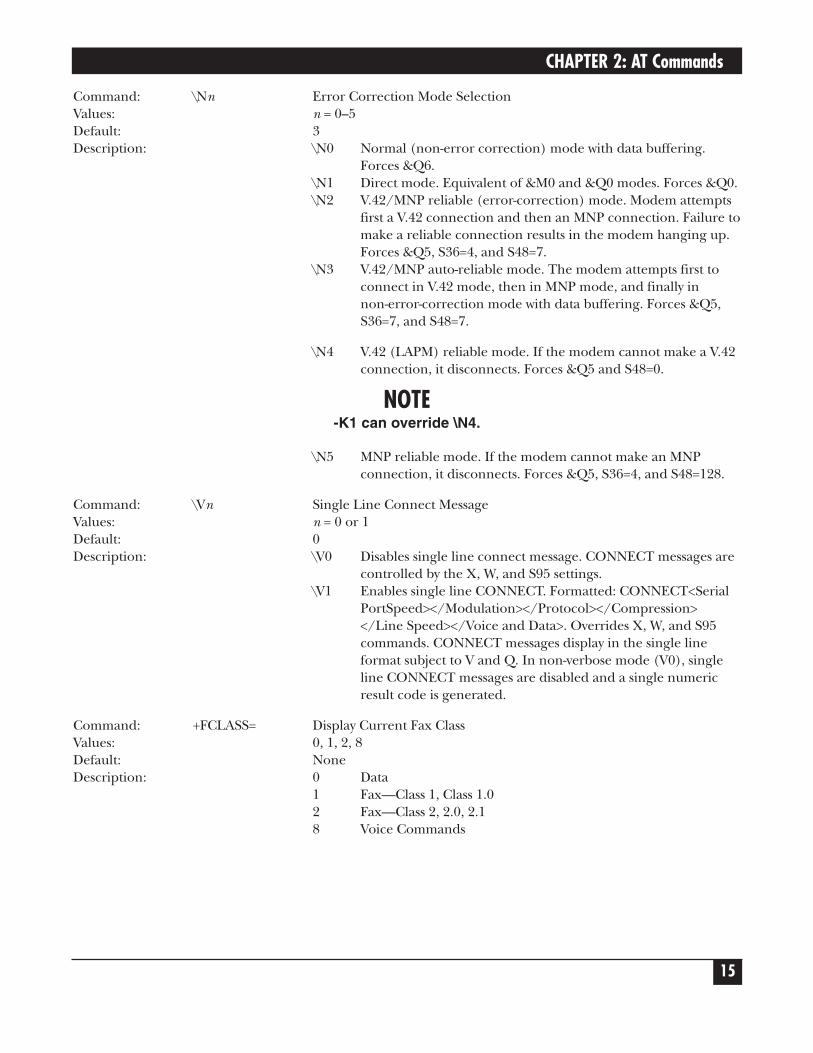
Command: \Nn Error Correction Mode SelectionValues: n = 0–5Default: 3Description: \N0 Normal (non-error correction) mode with data buffering.
Forces &Q6.\N1 Direct mode. Equivalent of &M0 and &Q0 modes. Forces &Q0.\N2 V.42/MNP reliable (error-correction) mode. Modem attempts
first a V.42 connection and then an MNP connection. Failure tomake a reliable connection results in the modem hanging up. Forces &Q5, S36=4, and S48=7.
\N3 V.42/MNP auto-reliable mode. The modem attempts first to connect in V.42 mode, then in MNP mode, and finally in non-error-correction mode with data buffering. Forces &Q5, S36=7, and S48=7.
\N4 V.42 (LAPM) reliable mode. If the modem cannot make a V.42connection, it disconnects. Forces &Q5 and S48=0.
NOTE-K1 can override \N4.
\N5 MNP reliable mode. If the modem cannot make an MNPconnection, it disconnects. Forces &Q5, S36=4, and S48=128.
Command: \Vn Single Line Connect MessageValues: n = 0 or 1Default: 0Description: \V0 Disables single line connect message. CONNECT messages are
controlled by the X, W, and S95 settings.\V1 Enables single line CONNECT. Formatted: CONNECT<Serial
PortSpeed></Modulation></Protocol></Compression></Line Speed></Voice and Data>. Overrides X, W, and S95 commands. CONNECT messages display in the single line format subject to V and Q. In non-verbose mode (V0), single line CONNECT messages are disabled and a single numeric result code is generated.
Command: +FCLASS= Display Current Fax ClassValues: 0, 1, 2, 8Default: NoneDescription: 0 Data
1 Fax—Class 1, Class 1.02 Fax—Class 2, 2.0, 2.18 Voice Commands
V.92 DIALUP 2-WIRE OR 4-WIRE LEASED-LINE DATA/FAX MODEM AT COMMANDS GUIDE
16
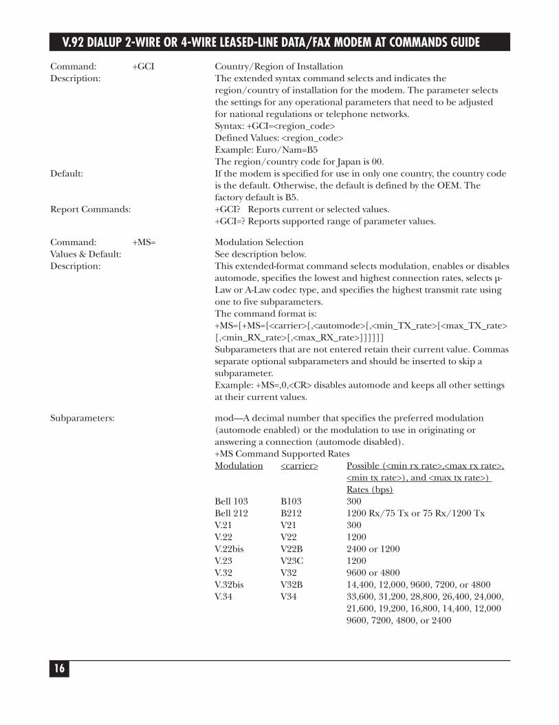
Command: +GCI Country/Region of InstallationDescription: The extended syntax command selects and indicates the
region/country of installation for the modem. The parameter selects the settings for any operational parameters that need to be adjusted for national regulations or telephone networks.Syntax: +GCI=<region_code>Defined Values: <region_code>Example: Euro/Nam=B5The region/country code for Japan is 00.
Default: If the modem is specified for use in only one country, the country code is the default. Otherwise, the default is defined by the OEM. The factory default is B5.
Report Commands: +GCI? Reports current or selected values.+GCI=? Reports supported range of parameter values.
Command: +MS= Modulation SelectionValues & Default: See description below.Description: This extended-format command selects modulation, enables or disables
automode, specifies the lowest and highest connection rates, selects µ-Law or A-Law codec type, and specifies the highest transmit rate usingone to five subparameters.The command format is:+MS=[+MS=[<carrier>[,<automode>[,<min_TX_rate>[<max_TX_rate>[,<min_RX_rate>[,<max_RX_rate>]]]]]]Subparameters that are not entered retain their current value. Commasseparate optional subparameters and should be inserted to skip asubparameter.Example: +MS=,0,<CR> disables automode and keeps all other settingsat their current values.
Subparameters: mod—A decimal number that specifies the preferred modulation(automode enabled) or the modulation to use in originating oranswering a connection (automode disabled).+MS Command Supported RatesModulation <carrier> Possible (<min rx rate>,<max rx rate>,
<min tx rate>), and <max tx rate>)Rates (bps)
Bell 103 B103 300Bell 212 B212 1200 Rx/75 Tx or 75 Rx/1200 TxV.21 V21 300V.22 V22 1200V.22bis V22B 2400 or 1200V.23 V23C 1200V.32 V32 9600 or 4800V.32bis V32B 14,400, 12,000, 9600, 7200, or 4800V.34 V34 33,600, 31,200, 28,800, 26,400, 24,000,
21,600, 19,200, 16,800, 14,400, 12,0009600, 7200, 4800, or 2400
CHAPTER 2: AT Commands
17
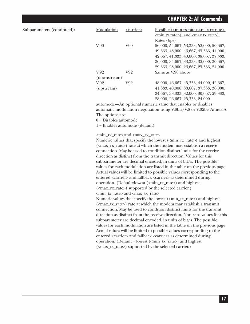
Subparameters (continued): Modulation <carrier> Possible (<min rx rate>,<max rx rate>,<min tx rate>), and <max tx rate>)Rates (bps)
V.90 V90 56,000, 54,667, 53,333, 52,000, 50,667,49,333, 48,000, 46,667, 45,333, 44,000,42,667, 41,333, 40,000, 38,667, 37,333,36,000, 34,667, 33,333, 32,000, 30,667,29,333, 28,000, 26,667, 25,333, 24,000
V.92 V92 Same as V.90 above(downstream)V.92 V92 48,000, 46,667, 45,333, 44,000, 42,667, (upstream) 41,333, 40,000, 38,667, 37,333, 36,000,
34,667, 33,333, 32,000, 30,667, 29,333,28,000, 26,667, 25,333, 24,000
automode—An optional numeric value that enables or disablesautomatic modulation negotiation using V.8bis/V.8 or V.32bis Annex A.The options are:0 = Disables automode1 = Enables automode (default)
<min_rx_rate> and <max_rx_rate>Numeric values that specify the lowest (<min_rx_rate>) and highest(<max_rx_rate>) rate at which the modem may establish a receiveconnection. May be used to condition distinct limits for the receivedirection as distinct from the transmit direction. Values for thissubparameter are decimal encoded, in units of bit/s. The possiblevalues for each modulation are listed in the table on the previous page.Actual values will be limited to possible values corresponding to theentered <carrier> and fallback <carrier> as determined duringoperation. (Default=lowest (<min_rx_rate>) and highest(<max_rx_rate>) supported by the selected carrier.)<min_tx_rate> and <max_tx_rate>Numeric values that specify the lowest (<min_tx_rate>) and highest(<max_tx_rate>) rate at which the modem may establish a transmitconnection. May be used to condition distinct limits for the transmitdirection as distinct from the receive direction. Non-zero values for thissubparameter are decimal encoded, in units of bit/s. The possiblevalues for each modulation are listed in the table on the previous page.Actual values will be limited to possible values corresponding to theentered <carrier> and fallback <carrier> as determined duringoperation. (Default = lowest (<min_tx_rate>) and highest(<max_tx_rate>) supported by the selected carrier.)
V.92 DIALUP 2-WIRE OR 4-WIRE LEASED-LINE DATA/FAX MODEM AT COMMANDS GUIDE
18
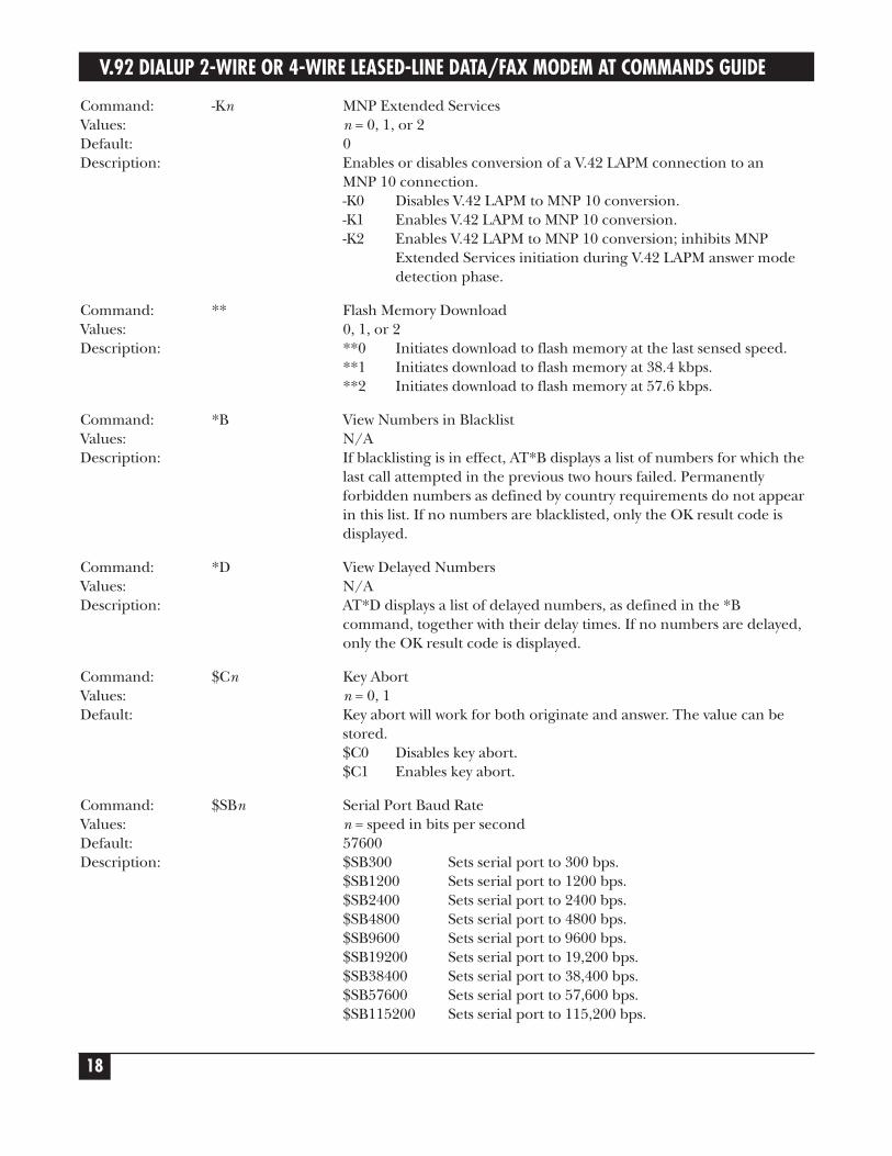
Command: -Kn MNP Extended ServicesValues: n = 0, 1, or 2Default: 0Description: Enables or disables conversion of a V.42 LAPM connection to an
MNP 10 connection.-K0 Disables V.42 LAPM to MNP 10 conversion.-K1 Enables V.42 LAPM to MNP 10 conversion.-K2 Enables V.42 LAPM to MNP 10 conversion; inhibits MNP
Extended Services initiation during V.42 LAPM answer mode detection phase.
Command: ** Flash Memory DownloadValues: 0, 1, or 2Description: **0 Initiates download to flash memory at the last sensed speed.
**1 Initiates download to flash memory at 38.4 kbps.**2 Initiates download to flash memory at 57.6 kbps.
Command: *B View Numbers in BlacklistValues: N/ADescription: If blacklisting is in effect, AT*B displays a list of numbers for which the
last call attempted in the previous two hours failed. Permanentlyforbidden numbers as defined by country requirements do not appearin this list. If no numbers are blacklisted, only the OK result code isdisplayed.
Command: *D View Delayed NumbersValues: N/ADescription: AT*D displays a list of delayed numbers, as defined in the *B
command, together with their delay times. If no numbers are delayed,only the OK result code is displayed.
Command: $Cn Key AbortValues: n = 0, 1Default: Key abort will work for both originate and answer. The value can be
stored.$C0 Disables key abort.$C1 Enables key abort.
Command: $SBn Serial Port Baud RateValues: n = speed in bits per secondDefault: 57600Description: $SB300 Sets serial port to 300 bps.
$SB1200 Sets serial port to 1200 bps.$SB2400 Sets serial port to 2400 bps.$SB4800 Sets serial port to 4800 bps.$SB9600 Sets serial port to 9600 bps.$SB19200 Sets serial port to 19,200 bps.$SB38400 Sets serial port to 38,400 bps.$SB57600 Sets serial port to 57,600 bps.$SB115200 Sets serial port to 115,200 bps.
CHAPTER 2: AT Commands
19
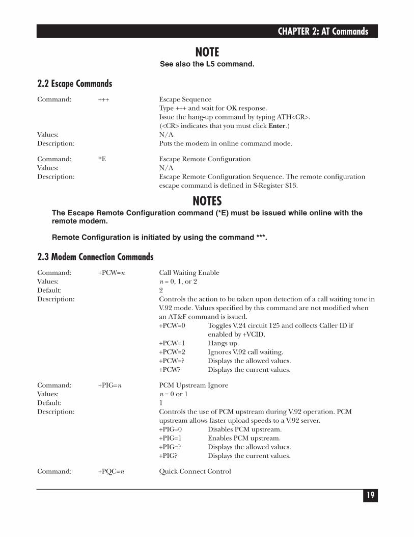
NOTESee also the L5 command.
2.2 Escape CommandsCommand: +++ Escape Sequence
Type +++ and wait for OK response.Issue the hang-up command by typing ATH<CR>.(<CR> indicates that you must click Enter.)
Values: N/ADescription: Puts the modem in online command mode.
Command: *E Escape Remote ConfigurationValues: N/ADescription: Escape Remote Configuration Sequence. The remote configuration
escape command is defined in S-Register S13.
NOTESThe Escape Remote Configuration command (*E) must be issued while online with theremote modem.
Remote Configuration is initiated by using the command ***.
2.3 Modem Connection CommandsCommand: +PCW=n Call Waiting EnableValues: n = 0, 1, or 2Default: 2Description: Controls the action to be taken upon detection of a call waiting tone in
V.92 mode. Values specified by this command are not modified whenan AT&F command is issued.+PCW=0 Toggles V.24 circuit 125 and collects Caller ID if
enabled by +VCID.+PCW=1 Hangs up.+PCW=2 Ignores V.92 call waiting.+PCW=? Displays the allowed values.+PCW? Displays the current values.
Command: +PIG=n PCM Upstream IgnoreValues: n = 0 or 1Default: 1Description: Controls the use of PCM upstream during V.92 operation. PCM
upstream allows faster upload speeds to a V.92 server.+PIG=0 Disables PCM upstream.+PIG=1 Enables PCM upstream.+PIG=? Displays the allowed values.+PIG? Displays the current values.
Command: +PQC=n Quick Connect Control
V.92 DIALUP 2-WIRE OR 4-WIRE LEASED-LINE DATA/FAX MODEM AT COMMANDS GUIDE
20
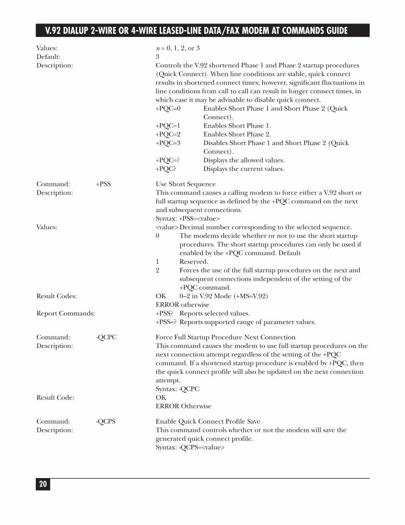
Values: n = 0, 1, 2, or 3Default: 3Description: Controls the V.92 shortened Phase 1 and Phase 2 startup procedures
(Quick Connect). When line conditions are stable, quick connectresults in shortened connect times; however, significant fluctuations inline conditions from call to call can result in longer connect times, inwhich case it may be advisable to disable quick connect.+PQC=0 Enables Short Phase 1 and Short Phase 2 (Quick
Connect).+PQC=1 Enables Short Phase 1.+PQC=2 Enables Short Phase 2.+PQC=3 Disables Short Phase 1 and Short Phase 2 (Quick
Connect).+PQC=? Displays the allowed values.+PQC? Displays the current values.
Command: +PSS Use Short SequenceDescription: This command causes a calling modem to force either a V.92 short or
full startup sequence as defined by the +PQC command on the next and subsequent connections.Syntax: +PSS=<value>
Values: <value> Decimal number corresponding to the selected sequence.0 The modems decide whether or not to use the short startup
procedures. The short startup procedures can only be used if enabled by the +PQC command. Default
1 Reserved.2 Forces the use of the full startup procedures on the next and
subsequent connections independent of the setting of the +PQC command.
Result Codes: OK 0–2 in V.92 Mode (+MS=V.92)ERROR otherwise
Report Commands: +PSS? Reports selected values.+PSS=? Reports supported range of parameter values.
Command: -QCPC Force Full Startup Procedure Next ConnectionDescription: This command causes the modem to use full startup procedures on the
next connection attempt regardless of the setting of the +PQCcommand. If a shortened startup procedure is enabled by +PQC, then the quick connect profile will also be updated on the next connection attempt.Syntax: -QCPC
Result Code: OKERROR Otherwise
Command: -QCPS Enable Quick Connect Profile SaveDescription: This command controls whether or not the modem will save the
generated quick connect profile.Syntax: -QCPS=<value>
CHAPTER 2: AT Commands
21
Values: 0, 1<value> Decimal number corresponding to the desired operation.0 Do not allow the quick connect profile to be saved.1 Allow the quick connect profile to be saved. Default
Result Codes: OK 0 or 1 in V.92 Mode (+MS=V.92) and quick connect is enabled (+PSS=0)ERROR otherwise
Report Commands: -QCPS? Reports selected value.-QCPS=? Reports supported range of parameter values.
2.4 Caller ID CommandsCommand: +VCID=n Caller ID SelectionValues: n = 0, 1, or 2Default: 0Description: Enables Caller ID detection and configures the reporting and
presentation of the Caller ID data that is detected after the first ring.The reported data includes the date and time of the call, the caller’sname and number, and a message. Set S0=2.+VCID=0 Disables Caller ID.+VCID=1 Enables Caller ID with formatted data.+VCID=2 Enables Caller ID with unformatted data.+VCID=? Displays the allowed values.+VCID? Displays the current values.
Command: +VRID= Caller ID Report RetrievedValues: 0, 1Default: 0Description: This command reports the data associated with the Caller ID services in
the incoming Call Line ID (ICLID) data format for the last receivedcall.+VRID=0 Reports Caller ID with formatted presentation to the
DTE. Data includes date, time, name, and telephone number.
+VRID=1 Reports Caller ID with unformatted presentation to the DTE.
+VRID=? Displays the supported range of parameter values.+VRID Displays Caller ID information of the last call received.
V.92 DIALUP 2-WIRE OR 4-WIRE LEASED-LINE DATA/FAX MODEM AT COMMANDS GUIDE
22
2.5 Callback Security CommandsCommand: #CBNn=[-]x Store Callback NumberValues: n = 01–30
x = dialing stringDefault: NoneDescription: Stores the callback dialing string x in a memory location. The dialing
string can include the digits 0 through 9 and any of the followingcharacters:#, *, comma (,), semicolon (;), W, A, B, C, and D.Up to 30 characters can be used. For example: AT#CBN01=9,16127853000.If the optional - character precedes the dialing string, and the callerappends the same character to the password, the caller is immediatelyconnected.
Command: #CBPn=x Store Callback PasswordValues: n = 01–30
x = password (6–10 characters)Default: NoneDescription: Stores callback security password x in memory location y. The password
must have 6 to 10 characters. For example: AT#CBP01=gilamep.
NOTEA direct connect password may not end with a hyphen (-).
Command: #DBn Callback Enable/DisableValues: n = 0 or 1Default: 0Description: Enables or disables callback security. When callback security is enabled,
phone number memory locations 0–4, used for quick dialing and DTRdialing, become unavailable and are replaced by callback securitymemory locations 1–30. The phone number memory locations andtheir contents are restored when callback security is disabled.#DB0 Disables callback security.#DB1 Enables callback security.
CHAPTER 2: AT Commands
23
2.6 Data Compression CommandsCommands: +DR Data Compression ReportingValues: 0, 1Default: This extended format numeric parameter controls whether or not the
extended-format +DR: intermediate result code is transmitted from the modem to the DTE. S95 bit 5 is reset to 0 for +DR=0 and is set to a 1 for +DR=1. The more recent setting of +DR or S95 bit 5, and the W command setting, determines the actual data compression result code reporting (see S95 Parameter and W Command).+DR0 Data compression reporting disabled (no +DR result code
transmitted).+DR1 Data compression reporting enabled (+DR result code
transmitted).+DR <type> Intermediate result code. The +DR: <type> reported
represents the current (negotiated or renegotiated)modem–modem data compression type. If enabled, the intermediate result code is transmitted at the point after error control negotiation (handshaking) at which time the modemhas determined which data compression technique will be used (if any) and the direction of operation. The +DR intermediate result code, if enabled, is issued after the error control report (+ER) and before the final result code (for example, CONNECT).
Report Commands: +DR? Reports current or selected values.+DR=? Reports supported range of parameter values.
Command: +DS Data CompressionValues: <direction> Specifies the desired direction(s) of operation of the
data compression function; from the DTE point of view.+DS0 Negotiated; no compression (V.42bis P0=0).+DS3 Both directions, accept any direction (V.42bis P0=11).<compr_neg> Specifies whether or not the modem should continue to operate if the desired result is not obtained.+DS0 Do not disconnect if V.42bis is not negotiated by the remote modem as specified in <direction>.<max_dict> Specifies maximum number of dictionary entries (2048 entries) that should be negotiated (may be used by the DTE to limit the code word size transmitted, based on its knowledge of the data to be transmitted).<max_string> Specifies maximum string length (32 bytes) to be negotiated (V.42bis P2).
Default: 3Description: This extended-format compound parameter controls the V.42bis data
compression function if provided in the modem. It accepts four numeric subparameters:+DS=[<direction>[,<compr_neg>[,<max_dict>[,<max_string>]]]]
Report Commands: +DS? Reports current of selected values.+DS=? Reports supported range of parameter values.
V.92 DIALUP 2-WIRE OR 4-WIRE LEASED-LINE DATA/FAX MODEM AT COMMANDS GUIDE
24
Command: +DS44 V.44 Compression SelectDescription: <direction> The decimal number that specifies the desired direction(s)
of operation of the data compression function; from the DTE point of view.0 Negotiated, no compression.1 Transmit only.2 Receive only.3 Both directions, accept any direction. Default<compress_negotiation> The decimal number that specifies whether or not the modem should continue to operate if the desired result is not obtained.0 Do not disconnect if V.44 is not negotiated by remote DCE as
specified in <direction>. Default.1 Disconnect if V.44 is not negotiated by remote DCE as specified
in <direction>.<capability> The decimal number that specifies the use of stream method, packet method, multi-packet method.0 Stream method. Default1 Packet method.2 Multi-packet method.<max_codewords_tx> The decimal number from 256 to 2048 that specifies the maximum number of code words that should be negotiated in the transmit direction. Default=2048<max_codewords_rx> The decimal number from 256 to 2048 that specifies the maximum number of code words that should be negotiated in the receive direction.<max_string_tx> The decimal number from 32 to 255 (maximum string length).
2.7 Error Control CommandsCommand: +EB Break Handling in Error Control OperationDescription: This extended-format compound parameter controls the break
handling in V.42 operation. It accepts three numeric subparameters.+EB=[<break_selection>[,<timed>[,default_length>]]]
Subparameters: <break_selection> Decimal number 0 specifying that any transmitted V.42 L-SIGNAL will not indicate break signal length.<timed> Decimal number 0 specifying that break is not delivered to the DTE.<timed> Decimal number 0 specifying that any transmitted V.42 L-SIGNAL will not indicate break signal length.<default_length> Decimal number 0 specifying that break is not delivered to the DTE.
Report Commands: +EB? Reports current or selected values.+EB=? Reports supported range of parameter values.
CHAPTER 2: AT Commands
25
Command: +EFCS 32-bit Frame Check SequenceDescription: This extended-format numeric parameter controls the use of the 16-bit
or 32-bit frame check sequence (FCS) option in V.42.Values: <value> Decimal number 0 specifying the use of the 16-bit FCS
specified in V42.+EFCS? Reports current or selected values.+EFCS=? Reports supported range of parameter values.
Command: +ER Error Control ReportingDescription: This extended-format numeric parameter controls whether or not the
intermediate result code is transmitted from the modem to the DTE.S95 bit 3 is reset to 0 for +ER=0 and is set to a 1 for +ER=1. The more recent setting of +ER or S95 bit 3, and the W command setting, determines the actual error control result code reporting (see S95 Parameter and W Command).
Values: 0, 10=Error control reporting disabled (no +ER intermediate result code transmitted).1=Error control reporting enabled (+ER intermediate result code transmitted).
Default: 0Report Commands: +ER? Reports current or selected values.
+ER=? Reports supported range of parameter values.
Command: +ES Error Control SelectionDescription: This extended format command specifies the initial requested mode of
operation when the modem is operating as the originator, and optionally specifies the acceptable fallback mode of operation when the modem is operating as the answering modem. It accepts three numeric subparameters: +ES=[<orig_rqst>[,<orig_fbk>[,<ans_fbk>]]]
Subparameters: <orig_rqst> Decimal number that specifies the initial requested mode of operation when the modem is operating as the originator. The options are:0 Initiate call with Direct Mode.1 Initiate call with Normal Mode (also referred to as Buffered
Mode) only.2 Initiate V.42 without Detection Phase. If V.8 is in use, disable
V.42 Detection Phase.3 Initiate V.42 with Detection Phase. Default.4 Initiate MNP.7 Initiate Frame Tunneling Mode when connection is complete
and Data Mode is entered.<orig_fbk> Decimal number that specifies the acceptable fallback mode of operation when the modem is operating as the originator.0 LAPM, MNP, or Normal Mode error control optional. Default.1 LAPM, MNP, or Direct Mode error control optional.2 LAPM or MNP error control required; disconnect if error
control is not established.
V.92 DIALUP 2-WIRE OR 4-WIRE LEASED-LINE DATA/FAX MODEM AT COMMANDS GUIDE
26
Subparameters (continued): 3 LAPM or MNP error control required; disconnect if error control is not established.
4 MNP error control required; disconnect if error control is not established.
<ans_fbk> Decimal number that specifies the acceptable fallback mode of operation when the modem is operating as the answering modem.0 Direct Mode.1 Error control disabled, use Normal Mode.2 LAPM, MNP, or Normal Mode error control optional. Default3 LAPM, MNP, or Direct Mode error control optional.4 LAPM or MNP error control required; disconnect if error
control is not established.5 LAPM error control required; disconnect if error control is not
established.6 MNP error control required; disconnect if error control is not
established.Report Commands: +ES? Reports current or selected values.
+ES=? Reports supported range of parameter values.
Command: +ESR Selective RejectDescription: This extended-format numeric parameter controls the use of the
selective reject (SREJ) option in V.42.Syntax: +ESR=[<value>]Decimal number 0 specifying that SREJ is not used.
Report Commands: +ESR? Reports current or selected values.+ESR=? Reports supported range of parameter values.
Command: +ETBM Call Termination Buffer ManagementDescription: This extended-format compound parameter controls the handling of
data remaining in modem buffers upon call termination. It accepts three numeric subparameters:Syntax: +ETBM=[<pending_TD>[,<pending_RD>[,<timer>]]]
Values: <pending_TD>Decimal number 0 specifying that disconnect will occur immediately and all buffered transmit data will be discarded when the local DTE requests call disconnection.<pending_RD>Decimal number 0 specifying that disconnect will occur immediately and all buffered receive data will be discarded when the local DTE requests call disconnection.<timer>Decimal number 0 specifying that the modem will not attempt to deliver the buffered data before abandoning the attempt and discarding remaining data.
Report Commands: +ETBM? Reports current or selected values.+ETBM=? Reports supported range of parameter values.
CHAPTER 2: AT Commands
27
2.8 DTE CommandsCommand: +IFC DTE-Modem Local Flow ControlDescription: This extended-format compound parameter controls the operation of
local flow control between the DTE and the modem during the data state when V.42 error control is used or when fallback to non-error control mode is specified to include buffering and flow control. It accepts two numeric subparameters.Syntax: +IFC=[<modem_by_DTE>[,<DTE_by_modem>]]
Values: <modem_by_DTE> Specifies the method the DTE will use to control flow of received data from the modem.0 None.1 X-ON/X-OFF on transmitted data; do not pass X-ON/X-OFF
characters to remote modem.2 Circuit 133 (RR). Default.3 DC1/DC3 on circuit 103 (TD) with DC1/DC3 characters being
passed through to the remote DCE in addition to being acted upon for local flow control.
<DTE_by_modem> Specifies the method the modem will use to control flow of transmitted data from the DTE.0 None.1 X-ON/X-OFF on received data.2 CTS/RTS. Default.
Report Commands: +IFC? Reports current or selected values.+IFC=? Reports supported range of parameter values.
Command: +ILRR DTE-Modem Local Rate ReportingDescription: This extended-format numeric parameter controls whether or not the
+ILRR:<rate> information text is transmitted from the modem to the DTE.Syntax: +ILRR=<value>
Values: <value> Decimal number corresponding to the selected option.0 Disables reporting of local port rate (+ILR: is not transmitted).
Default.1 Enables reporting of local port rate (+ILRR: is transmitted).
Report Commands: +ILRR? Reports current or selected values.+ILRR=? Reports supported range of parameter values.
V.92 DIALUP 2-WIRE OR 4-WIRE LEASED-LINE DATA/FAX MODEM AT COMMANDS GUIDE
28
Reported Rate: The <rate> reported is the current (negotiated or renegotiated)DTE-modem rate. If enabled, an intermediate result code is transmitted after any modulation, error control, or data compression reports are transmitted and before any final result code is transmitted.The <rate> is applied after the final result code is transmitted. The DTE-modem port rate changes only if neither buffered mode nor error controlled means are enabled (+ES = x, 0) and if the negotiated carrier rate (+MRR) does not match the current DTE-modem port rate (autodetected from previous command line).Syntax: +ILRRL: <rate>[,<rx_rate>].Reported rate values:<rate> Decimal value representing the current (negotiated or renegotiated) DTE-modem rate: 0, 300, 1200, 2400, 4800, 9600, 19,200, 38,400, 57,600, 115,200, 230,400.<rx_rate> Optional decimal value reporting the RXD rate, if it is different from the TXD rate: 0, 300, 1200, 2400, 4800, 9600, 19,200, 38,400, 57,600, 115,200, or 230,400.
Command: +IPR Fixed DTE RateDescription: This numeric extended-format parameter specifies the data rate at
which the modem will accept commands during online operation. It may be used to select operation at rates at which the modem is not capable of automatically detecting the data rate being used by the DTE.Specifying a value of 0 disables the function and allows operation only at rates at which the modem is not capable of automatically detecting the data rate being used by the DTE.Specifying a value of 0 disables the function and allows operation only at rates automatically detectable by the modem. The specified rate takes effect following any issued result code(s) associated with the current command line.The <rate> specified does not apply in OnLine Data State if Normal Mode (Direct Mode) of operation is selected.Syntax: +IPR=<rate>
Values: <rate> Specifies the DTE-modem interface operation rate in bits/s. The available rates are: 0, 300, 1200, 2400, 4800, 9600, 19,200, 38,400, 57,600, 115,200, or 230,400.If unspecified or set to 0, automatic detection is selected and the character format is also forced to auto detect. +ICF=0.If the specified rate is not supported by the modem, an ERROR result will be returned.
Report Commands: +IPR? Reports current or selected values.+IPR=? Reports supported range of parameter values.
CHAPTER 2: AT Commands
29
2.9 Modulation CommandCommand: +MR Modulation Reporting ControlDescription: This extended-format numeric parameter controls whether or not the
extended-format +MCR:<carrier> and +MRR:<rate> intermediate result codes are transmitted from the modem to the DTE. If enabled, +MCR:<carrier> and +MRR:<rate> intermediate result codes represent the current (negotiated or renegotiated) modulation <carrier> and <rate> that are transmitted at the point during connect negotiation (handshaking) at which the modem has determined which modulation and data rate will be used. This happens before any Error Control or Data Compression reports are transmitted and before any final result code (for example, CONNECT) is transmitted.S95 bit 2 is reset to 0 for +MR=0 and is set to a 1 for +MR=1 or +MR=2. The more recent setting of +MR or S95 bit 2 and the W command setting determines modulation result code reporting (see S95 Parameter and W Command).Syntax: +MR=[<value>]
Values: <value> A decimal number corresponding to the selected option:0 Disables reporting of modulation connection (+MCR: and
+MRR: are not transmitted). Default.1 Enables reporting of modulation connection (+MCR: and
+MRR: are transmitted with Tx rate, Rx rate).2 Enables reporting of modulation connection (+MCR: and
+MRR: are transmitted with Rx rate only).Report Commands: +MR? Reports current or selected values.
+MR=? Reports supported range of parameter values.+MCR: Report Syntax: Response: +MCR: <carrier><carrier> Alphanumeric code corresponding to the reported carrier.Defined values are:B103 for Bell 103B212 for Bell 212V21 for V.21V22 for V.22V22B for V.22bisV23C for V.23V32 for V.32V32B for V.32bisV34 for V.34V90 for V.90V92 for V.92
+MRR: Report Syntax: Response: +MRR: <tx_rate>,<rx_rate><tx_rate> Decimal transmit rate in bits/s.<rx_rate> Decimal receive rate in bits/s.
V.92 DIALUP 2-WIRE OR 4-WIRE LEASED-LINE DATA/FAX MODEM AT COMMANDS GUIDE
30
2.10 Call Control CommandCommand: -STE= Set Telephony ExtensionDescription: This command enables/disables line-in-use, extension pickup, and
remote hangup detection features.
NOTEAdditional hardware may be required to support these features.
Syntax: -STE=<value>Values: <value> Decimal number corresponding to the selected bit-mapped
options.The bit fields are defined as follows:Bit 0 Line-In-Use detection—enable/disable.Bit 1 Extension Pickup—detection enable/disable.Bit 2 Remote Hangup—detection enable/disable.
<value> Remote Extension Line-in-Use(decimal) Hangup Pickup0 (default) Disabled Disabled Disabled1 Disabled Disabled Enabled2 Disabled Enabled Disabled3 Disabled Enabled Enabled4 Enabled Disabled Disabled5 Enabled Disabled Enabled6 Enabled Enabled Disabled7 Enabled Enabled Enabled
Report Commands: -STE? Reports current or selected values-STE=? Reports supported range of parameter values
Result Codes: OK <value> = 0–7ERROR Otherwise.
Behavior in Data Mode (+FCLASS=0): When on-hook, if the line is in use and an ATDT is issued, the modemwill not go off-hook and will return with the message LINE-IN-USE.When off-hook and either an extension is picked up or a line reversal isdetected, the modem will drop the connection. The disconnect reasonis register S86=25 (also defined for #UD). The user must flash the hookin order to get a dial tone because the remote server will be retraining.If the local handset is picked up while modem is off-hook, the modemwill do a link-disconnect, flash the hook for 1.5 seconds, then connectthe local handset to the line. Now, the user dial tone is on the localhandset. Disconnect reason S86=25.
Behavior in Voice Mode (+FCLASS=8): When in voice mode and an extension is picked-up, a <DLE>P is sent tothe DTE. When the modem is off-hook, a line reversal may also bedetected in which case a <DLE>l is sent to the DTE.In voice mode, there is no blocking of ATDT when the line is in use.Also, there is no automatic hang-up in voice mode as in data mode.There is only the above stated <DLE> shielding event reporting.
CHAPTER 2: AT Commands
31
Operation in Data Mode: Line-In-Use (Enabled by AT-STE=1, AT-STE=3, AT-STE=5, orAT-STE=7)Case 1: Telephone Line is in UseIf an ATDT, ATDP, or ATDL is issued while Line-In-Use detection isenabled and the telephone line is in use, the modem will immediatelyreturn the message LINE-IN-USE to the DTE without going off-hook,then return to command mode.Case 2: Telephone Line is in Use But DisconnectedIf an ATDT, ATDP, or ATDL is issued while Line-In-Use detection isenabled and the telephone line is NOT in use, the modem will go off-hook after a short pause, then respond with CONNECT or NOCARRIER message.Case 3: Telephone Line is Not Connected to ModemIf an ATDT, ATDP, or ATDL is issued while Line-In-Use detection isenabled and the telephone line is not connected, the modem will gooff-hook momentarily, go back on-hook, then respond with NO DIALTONE message.Extension Pick-up (Enabled by AT-STE=2, AT-STE=3, AT-STE=6, orAT-STE=7):Case 1: Modem Off-Hook, Local Handset Goes Off-HookIf the local handset goes off-hook while the modem is in a dataconnection, the modem will then send a GSTN Clear down to theremote modem and then go on-hook. The modem will then send a NOCARRIER message to the DTE. A result code of 25 will be left in S86register.Remote Hang-up (enabled by AT-STE=4, AT-STE=5, AT-STE=6, or AT-STE=7):Case 1: Modem Off-Hook, Remote Hang-UpIf the modem is connected (off-hook) and the remote modem/serverhangs up, the central office may issue a line polarity reversal. If a linepolarity reversal is detected, the modem will drop the call and respondwith NO CARRIER. The reason for hang-up can be determined by #UDor by S86=25. A line reversal can also be simulated by simply pullingout the telephone line during a connection.
Operation in Voice Mode: Line-In-Use (enabled by AT-STE=1, AT-STE=3, AT-STE=5, orAT-STE=7):This feature does not apply in voice mode.Extension Pickup (Enabled by AT-STE=2, AT-STE=3, AT-STE=6, orAT-STE=7)If the modem is off-hook and an extension goes off-hook, the modemissues a <DLE>P to the DTE. The application software then hangs upthe line (VLS=0).Remote Hang-up (Enabled by AT-STE=4, AT-STE=5, AT-STE=6, orAT-STE=7).If the modem is off-hook and the remote user goes on-hook, themodem issues a <DLE>P to the DTE. The application software thenhangs up the line (VLS=0).
V.92 DIALUP 2-WIRE OR 4-WIRE LEASED-LINE DATA/FAX MODEM AT COMMANDS GUIDE
32
Examples: User is talking on an extension and the modem tries to dialAT-STE=7ATDT555-1212LINE-IN-USEThe line is not in use and the modem tries to dialAT-STE=7ATDT555-1212Modem goes off-hookCONNECTAn extension is off-hook but there is silence on the line and themodem tries to dialAT-STE=3ATDT555-1212Modem goes off-hookNO DIAL TONEModem is connected in data mode and remote modem goes on-hookAT-STE=4ATDT555-1212CONNECTNO CARRIER Remote modem drops lineATS86=?025Modem is in answer machine mode and an extension goes off-hookAT-STE=2AT+FCLASS=8OK<DLE>h Local handset on-hook<DLE>R RingAT+VLS=1OKAT+VSM=1,8000AT+VTX Starts to play greeting message<DLE>P User picks up extension<DLE>! DTE sends abort to end playbackAT+VLS=0 DTE hangs up.Automated system that needs to periodically use the line while givingthe voice user the highest priorityAn automated system that needs to periodically use the line whilegiving the voice user the highest priority. The automated system makesa connection when the line is free. It does this without disturbing theline if the line is in use. The automated system periodically retries theconnection until the line is free.Once free, it dials and makes its connection. If a voice user wishes touse the line while the modem is connected, the modem drops the lineand gives it to the user. The modem will then try to regain control ofthe line by once again periodically retrying to establish a connection.AT-STE=7OKATDT5551212
CHAPTER 2: AT Commands
33
Examples (continued): CONNECTSometime later, the user picks up phoneNO CARRIERATS86?25OKDelay 30 secondsATDT5551212LINE-IN-USETry again some time later, user hangs up the phoneCONNECT
2.11 Test CommandCommand: &Tn V.54 Test Command Values: n = 0, 1, 8 Default: None Description: The modem can perform selected test and diagnostic functions. A test
can be run only when the modem is in asynchronous operation in non-error-correction mode (normal or direct mode). To terminate a test in progress, the escape sequence (+++) must be entered first. &T0 Abort. Stop any test in progress.&T1 Start local analog loopback, V.54 Loop 3. If a connection exists
when this command is issued, the modem hangs up. A CONNECT message is displayed at the start of the test.
&T8 Starts local analog loopback, V.54 Loop 3, with self-test. If aconnection exists, the modem hangs up before the test begins.When the test is terminated, the number of detected errors isreported to the computer.
V.92 DIALUP 2-WIRE OR 4-WIRE LEASED-LINE DATA/FAX MODEM AT COMMANDS GUIDE
34
3. V.8/V.8bis CommandsV.8 is a way V.34 modems negotiate connections features and options. V.8bis is a start-up sequence formultimedia modems.
Command: +A8E V.8 and V.8bis Operation Controls
Description: This command is defined for two conditions: as a parameter while themodem is on-hook, and as an action command while the modem isoff-hook. If enabled, V.8 negotiation does not preclude simultaneousimplementation of other negotiation means (for example, V.8bis, V.18,V.32bis Annex A). It is a compound parameter if issued while themodem is on-hook, used to precondition V.8 and V.8bis originating andanswering operation. It is issued by the DTE before the Dial (D) orAnswer (A) command, regardless of the state of the +FCLASSparameter. This command is an action command if issued while themodem is off-hook to (re)start V.8 or V.8bis negotiation.Example: If initial V.8 negotiation fails, but subsequent T.30 negotiationindicates V.8 capability, this command may be used to initiate V.8negotiation.Syntax: +A8E=<v8o>,<v8a>,<v8cf>[,<v8b>][,<cfrange>][,<protrange>]
Values: <v8o> Decimal number which enables/disables issuance of +A8x indications during modem-controlled V.8 origination negotiation.1 Enable DCE-controlled V.8 origination negotiation without
+A8x indications. Default.6 Enable DCE-controlled V.8 origination negotiation with +A8x
indications.<v8a>= Decimal number which enables/disables issuance of +A8x indications during modem-controlled V.8 answer negotiation.
1 Enable DCE-controlled V.8 answer negotiation without +A8x indications. Default
5 Enable DCE-controlled V.8 answer negotiation with +A8x indications.
<v8cf>= Set the V.8 CI signal call function to the hexadecimal octet XY00 Default21C1<v8b>= Decimal number which enables/disables V.8bis negotiation.0 Disable V.8bis negotiation.1 Enable V.8bis negotiation. Default<cfrange>= “<string of values>.” Applicable only for <v8a>=5. Notsupported.<protrange>= “<string of values>.” Applicable only for <v8a>=5. Notsupported.
CHAPTER 3: V.8/V.8bis Commands
35
Default Values: 1,1,00,1,0,0The ATD and ATA commands behave as specified in V.250, and +A8nindications are not generated by the modem. For subparameter values<v8o>=6 and <v8a>=5, +A8I indications are issued during the V.8sessionto notify the DTE when the relevant V.8 signals are received.
Report Commands: +A8E? Reports current or selected values.
+A8E=? Reports supported range of parameter values.
Command: +A8I CI Signal Indication
Description: This indication is issued by an answering modem, if +A8E,<v8a> .0, toindicate detection of a V.8 CI signal and report the recovered CallFunction octet(s).Indication Syntax: +A8I:<v8cf><CR>
Values: <v8cf> A hexadecimal code octet representation of those CallFunction octet(s).+A8I:0 indicates that the modem timed out waiting for CI.
Example: +A8I:0 The modem timed out waiting for CI.+A8I:X YYY
V.92 DIALUP 2-WIRE OR 4-WIRE LEASED-LINE DATA/FAX MODEM AT COMMANDS GUIDE
36
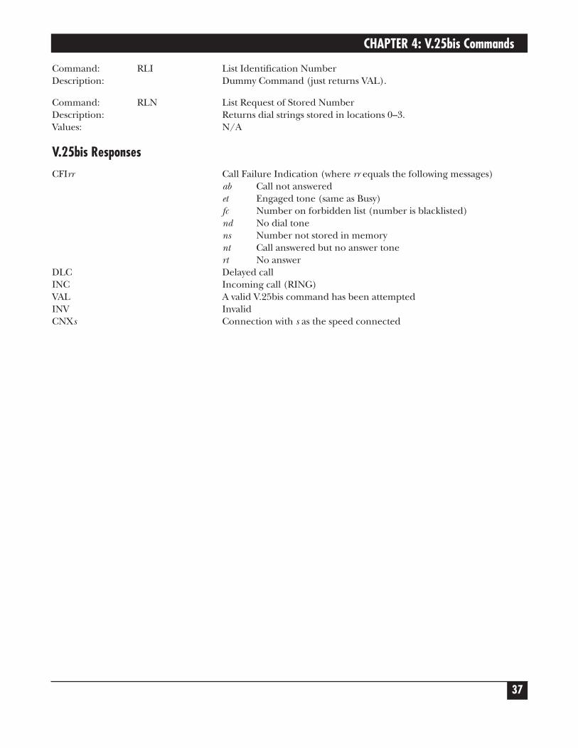
4. V.25bis CommandsThe V.25bis commands control synchronous communications between the host and the modem using theHDLC or character-oriented protocol. Modulation depends on the serial port rate and setting of thetransmitting clock source.
These commands apply to modems that support synchronous communications.
Command: CIC Connect Incoming CallDescription: Answers an incoming call.Values: N/A
Command: DIC Disregard Incoming CallDescription: Disregards current incoming call.Values: N/A
Command: CRNs Call Request NumberDescription: Used to dial a number Values: s = dial string (0–9, *, #, :, <, =, P, T)
Command: CRIs Call Request IdentificationDescription: Used to dial a numberValues: s = dial string (0–9, *, #, :, <, =, P, T)V.25bis Number Format: 0–9 Dialing Digit
: Wait tone< Pause= SeparatorP Dialing to be continued in Pulse modeT Dialing to be continue in DTMF
Command: PRNx;s Program NumberDescription: Used to store dial string s in location x.Values: x =(0–3)
s = dial string (0–9, *, #, :, <, =, P, T)
Command: CRSx Call Request AddressDescription: Recalls dial string to dial from location x.Values: x = (0–3)
Command: PRIa;s Program Identification Number Description: Dummy Command (just returns VAL).
Command: RLD List Request of Delayed Call NumberDescription: Returns current listing of delayed numbers.Values: N/A
Command: RLF List Request of Forbidden NumberDescription: Returns current listing of forbidden numbers.Values: N/A
CHAPTER 4: V.25bis Commands
37
Command: RLI List Identification NumberDescription: Dummy Command (just returns VAL).
Command: RLN List Request of Stored NumberDescription: Returns dial strings stored in locations 0–3.Values: N/A
V.25bis ResponsesCFIrr Call Failure Indication (where rr equals the following messages)
ab Call not answeredet Engaged tone (same as Busy)fc Number on forbidden list (number is blacklisted)nd No dial tonens Number not stored in memorynt Call answered but no answer tonert No answer
DLC Delayed callINC Incoming call (RING)VAL A valid V.25bis command has been attemptedINV InvalidCNXs Connection with s as the speed connected
V.92 DIALUP 2-WIRE OR 4-WIRE LEASED-LINE DATA/FAX MODEM AT COMMANDS GUIDE
38
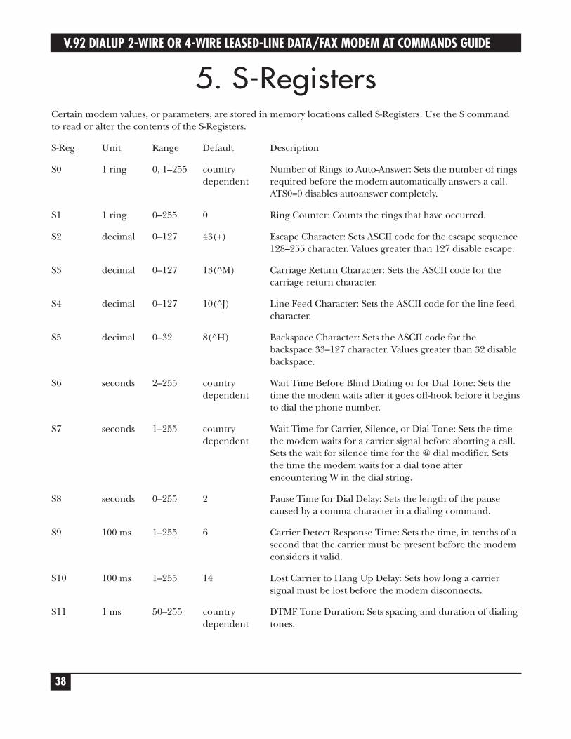
5. S-RegistersCertain modem values, or parameters, are stored in memory locations called S-Registers. Use the S commandto read or alter the contents of the S-Registers.
S-Reg Unit Range Default Description
S0 1 ring 0, 1–255 country Number of Rings to Auto-Answer: Sets the number of rings dependent required before the modem automatically answers a call.
ATS0=0 disables autoanswer completely.
S1 1 ring 0–255 0 Ring Counter: Counts the rings that have occurred.
S2 decimal 0–127 43(+) Escape Character: Sets ASCII code for the escape sequence128–255 character. Values greater than 127 disable escape.
S3 decimal 0–127 13(^M) Carriage Return Character: Sets the ASCII code for thecarriage return character.
S4 decimal 0–127 10(^J) Line Feed Character: Sets the ASCII code for the line feedcharacter.
S5 decimal 0–32 8(^H) Backspace Character: Sets the ASCII code for thebackspace 33–127 character. Values greater than 32 disablebackspace.
S6 seconds 2–255 country Wait Time Before Blind Dialing or for Dial Tone: Sets the dependent time the modem waits after it goes off-hook before it begins
to dial the phone number.
S7 seconds 1–255 country Wait Time for Carrier, Silence, or Dial Tone: Sets the time dependent the modem waits for a carrier signal before aborting a call.
Sets the wait for silence time for the @ dial modifier. Setsthe time the modem waits for a dial tone afterencountering W in the dial string.
S8 seconds 0–255 2 Pause Time for Dial Delay: Sets the length of the pausecaused by a comma character in a dialing command.
S9 100 ms 1–255 6 Carrier Detect Response Time: Sets the time, in tenths of asecond that the carrier must be present before the modemconsiders it valid.
S10 100 ms 1–255 14 Lost Carrier to Hang Up Delay: Sets how long a carriersignal must be lost before the modem disconnects.
S11 1 ms 50–255 country DTMF Tone Duration: Sets spacing and duration of dialing dependent tones.
CHAPTER 5: S-Registers
39
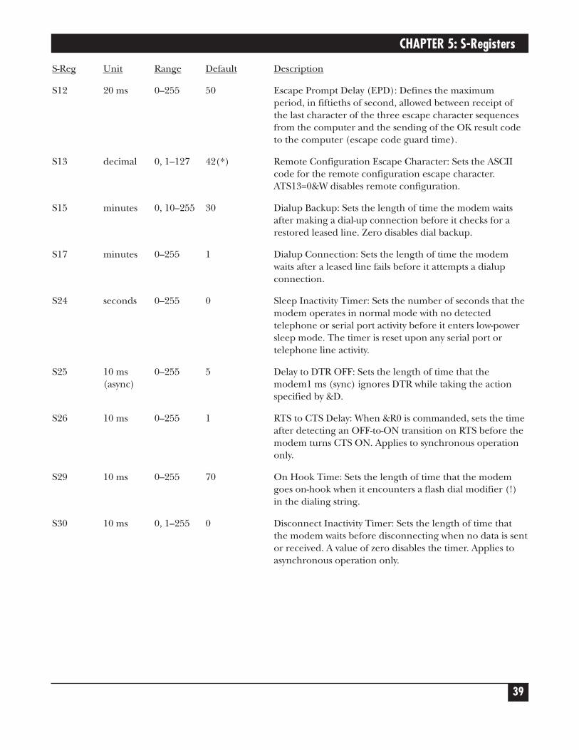
S-Reg Unit Range Default Description
S12 20 ms 0–255 50 Escape Prompt Delay (EPD): Defines the maximumperiod, in fiftieths of second, allowed between receipt ofthe last character of the three escape character sequencesfrom the computer and the sending of the OK result codeto the computer (escape code guard time).
S13 decimal 0, 1–127 42(*) Remote Configuration Escape Character: Sets the ASCIIcode for the remote configuration escape character.ATS13=0&W disables remote configuration.
S15 minutes 0, 10–255 30 Dialup Backup: Sets the length of time the modem waitsafter making a dial-up connection before it checks for arestored leased line. Zero disables dial backup.
S17 minutes 0–255 1 Dialup Connection: Sets the length of time the modemwaits after a leased line fails before it attempts a dialupconnection.
S24 seconds 0–255 0 Sleep Inactivity Timer: Sets the number of seconds that themodem operates in normal mode with no detectedtelephone or serial port activity before it enters low-powersleep mode. The timer is reset upon any serial port ortelephone line activity.
S25 10 ms 0–255 5 Delay to DTR OFF: Sets the length of time that the (async) modem1 ms (sync) ignores DTR while taking the action
specified by &D.
S26 10 ms 0–255 1 RTS to CTS Delay: When &R0 is commanded, sets the timeafter detecting an OFF-to-ON transition on RTS before themodem turns CTS ON. Applies to synchronous operationonly.
S29 10 ms 0–255 70 On Hook Time: Sets the length of time that the modemgoes on-hook when it encounters a flash dial modifier (!)in the dialing string.
S30 10 ms 0, 1–255 0 Disconnect Inactivity Timer: Sets the length of time thatthe modem waits before disconnecting when no data is sentor received. A value of zero disables the timer. Applies toasynchronous operation only.
V.92 DIALUP 2-WIRE OR 4-WIRE LEASED-LINE DATA/FAX MODEM AT COMMANDS GUIDE
40
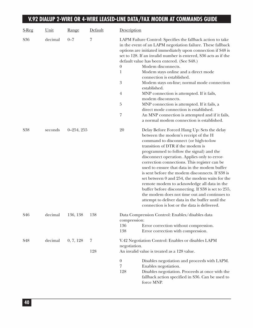
S-Reg Unit Range Default Description
S36 decimal 0–7 7 LAPM Failure Control: Specifies the fallback action to takein the event of an LAPM negotiation failure. These fallbackoptions are initiated immediately upon connection if S48 isset to 128. If an invalid number is entered, S36 acts as if thedefault value has been entered. (See S48.)0 Modem disconnects.1 Modem stays online and a direct mode
connection is established.3 Modem stays on-line; normal mode connection
established.4 MNP connection is attempted. If it fails,
modem disconnects.5 MNP connection is attempted. If it fails, a
direct mode connection is established.7 An MNP connection is attempted and if it fails,
a normal modem connection is established.
S38 seconds 0–254, 255 20 Delay Before Forced Hang Up: Sets the delaybetween the modem’s receipt of the Hcommand to disconnect (or high-to-lowtransition of DTR if the modem isprogrammed to follow the signal) and thedisconnect operation. Applies only to error-correction connections. This register can beused to ensure that data in the modem bufferis sent before the modem disconnects. If S38 isset between 0 and 254, the modem waits for theremote modem to acknowledge all data in thebuffer before disconnecting. If S38 is set to 255,the modem does not time out and continues toattempt to deliver data in the buffer until theconnection is lost or the data is delivered.
S46 decimal 136, 138 138 Data Compression Control: Enables/disables datacompression:136 Error correction without compression. 138 Error correction with compression.
S48 decimal 0, 7, 128 7 V.42 Negotiation Control: Enables or disables LAPM negotiation.
128 An invalid value is treated as a 128 value.
0 Disables negotiation and proceeds with LAPM.7 Enables negotiation.128 Disables negotiation. Proceeds at once with the
fallback action specified in S36. Can be used toforce MNP.
CHAPTER 5: S-Registers
41
S-Reg Unit Range Default Description
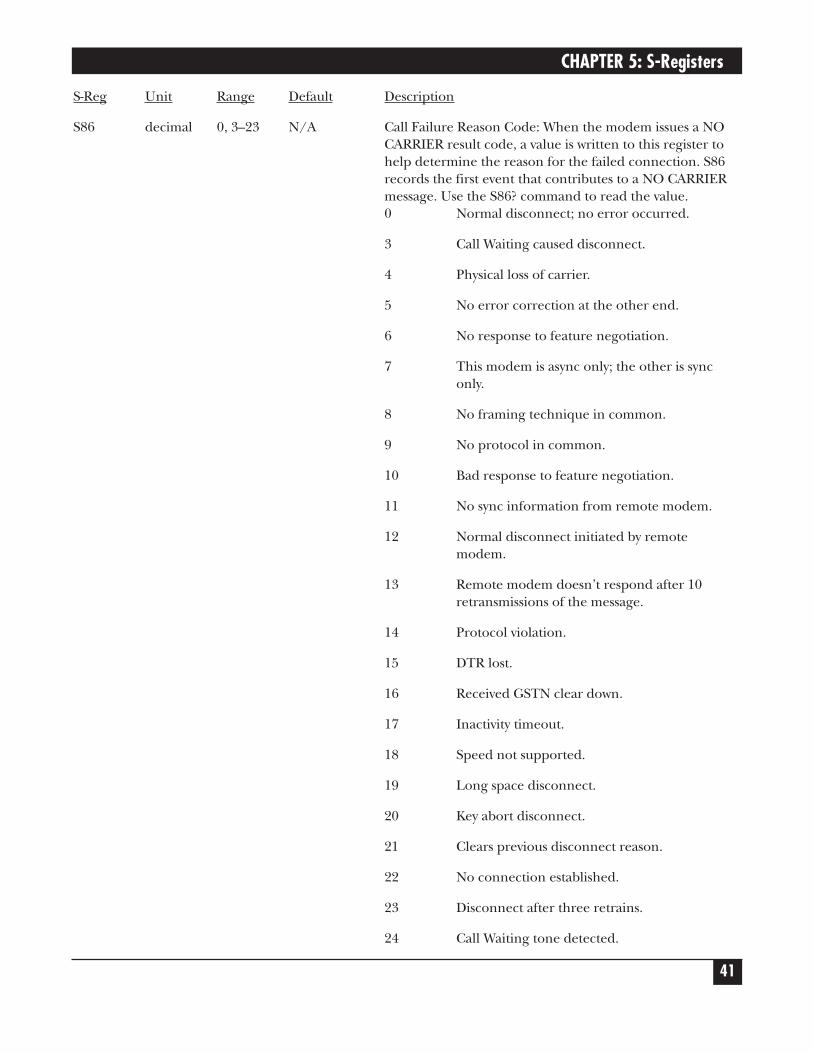
S86 decimal 0, 3–23 N/A Call Failure Reason Code: When the modem issues a NOCARRIER result code, a value is written to this register tohelp determine the reason for the failed connection. S86records the first event that contributes to a NO CARRIERmessage. Use the S86? command to read the value.0 Normal disconnect; no error occurred.
3 Call Waiting caused disconnect.
4 Physical loss of carrier.
5 No error correction at the other end.
6 No response to feature negotiation.
7 This modem is async only; the other is synconly.
8 No framing technique in common.
9 No protocol in common.
10 Bad response to feature negotiation.
11 No sync information from remote modem.
12 Normal disconnect initiated by remote modem.
13 Remote modem doesn’t respond after 10 retransmissions of the message.
14 Protocol violation.
15 DTR lost.
16 Received GSTN clear down.
17 Inactivity timeout.
18 Speed not supported.
19 Long space disconnect.
20 Key abort disconnect.
21 Clears previous disconnect reason.
22 No connection established.
23 Disconnect after three retrains.
24 Call Waiting tone detected.
V.92 DIALUP 2-WIRE OR 4-WIRE LEASED-LINE DATA/FAX MODEM AT COMMANDS GUIDE
42
S-Reg Unit Range Default Description
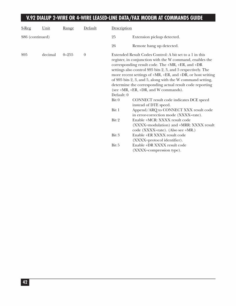
S86 (continued) 25 Extension pickup detected.
26 Remote hang up detected.
S95 decimal 0–255 0 Extended Result Codes Control: A bit set to a 1 in thisregister, in conjunction with the W command, enables thecorresponding result code. The +MR, +ER, and +DRsettings also control S95 bits 2, 3, and 5 respectively. Themore recent settings of +MR, +ER, and +DR, or host writingof S95 bits 2, 3, and 5, along with the W command setting,determine the corresponding actual result code reporting(see +MR, +ER, +DR, and W commands).Default: 0Bit 0 CONNECT result code indicates DCE speed
instead of DTE speed.Bit 1 Append/ARQ to CONNECT XXX result code
in error-correction mode (XXXX=rate).Bit 2 Enable +MCR: XXXX result code
(XXXX=modulation) and +MRR: XXXX result code (XXXX=rate). (Also see +MR.)
Bit 3 Enable +ER XXXX result code (XXXX=protocol identifier).
Bit 5 Enable +DR XXXX result code (XXXX=compression type).
CHAPTER 6: Result Codes
43
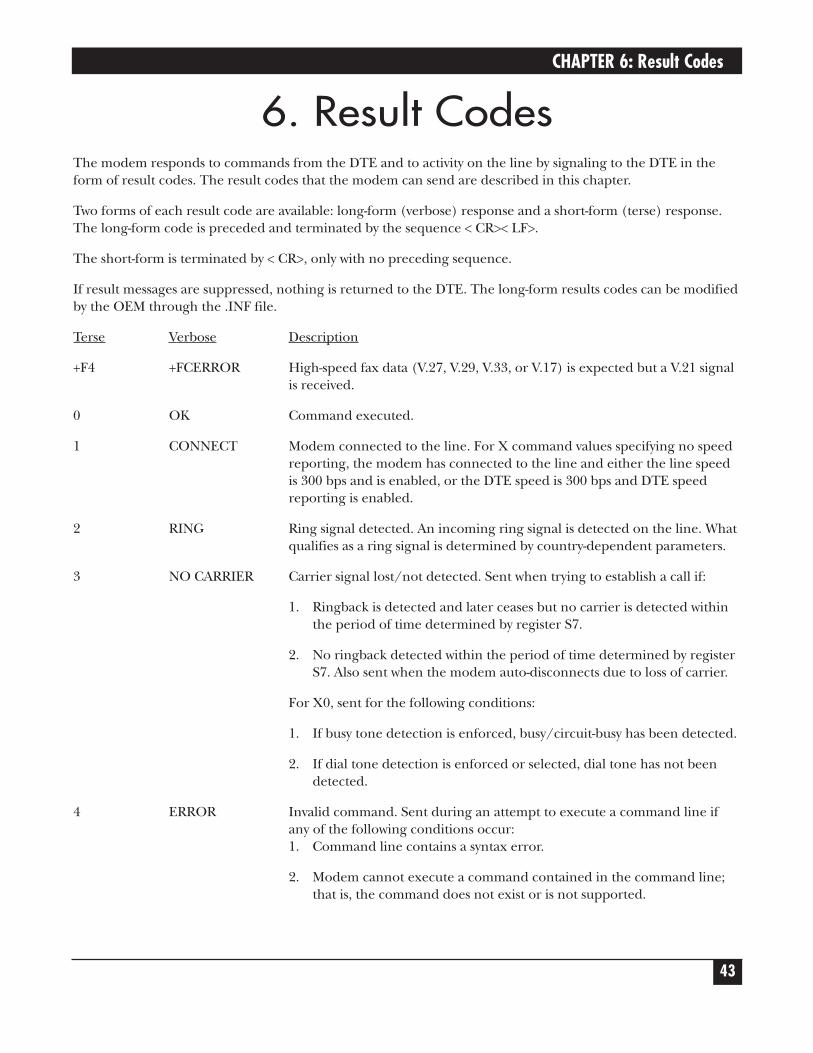
6. Result CodesThe modem responds to commands from the DTE and to activity on the line by signaling to the DTE in theform of result codes. The result codes that the modem can send are described in this chapter.
Two forms of each result code are available: long-form (verbose) response and a short-form (terse) response.The long-form code is preceded and terminated by the sequence < CR>< LF>.
The short-form is terminated by < CR>, only with no preceding sequence.
If result messages are suppressed, nothing is returned to the DTE. The long-form results codes can be modifiedby the OEM through the .INF file.
Terse Verbose Description
+F4 +FCERROR High-speed fax data (V.27, V.29, V.33, or V.17) is expected but a V.21 signalis received.
0 OK Command executed.
1 CONNECT Modem connected to the line. For X command values specifying no speedreporting, the modem has connected to the line and either the line speedis 300 bps and is enabled, or the DTE speed is 300 bps and DTE speedreporting is enabled.
2 RING Ring signal detected. An incoming ring signal is detected on the line. Whatqualifies as a ring signal is determined by country-dependent parameters.
3 NO CARRIER Carrier signal lost/not detected. Sent when trying to establish a call if:
1. Ringback is detected and later ceases but no carrier is detected withinthe period of time determined by register S7.
2. No ringback detected within the period of time determined by registerS7. Also sent when the modem auto-disconnects due to loss of carrier.
For X0, sent for the following conditions:
1. If busy tone detection is enforced, busy/circuit-busy has been detected.
2. If dial tone detection is enforced or selected, dial tone has not been detected.
4 ERROR Invalid command. Sent during an attempt to execute a command line ifany of the following conditions occur:1. Command line contains a syntax error.
2. Modem cannot execute a command contained in the command line;that is, the command does not exist or is not supported.
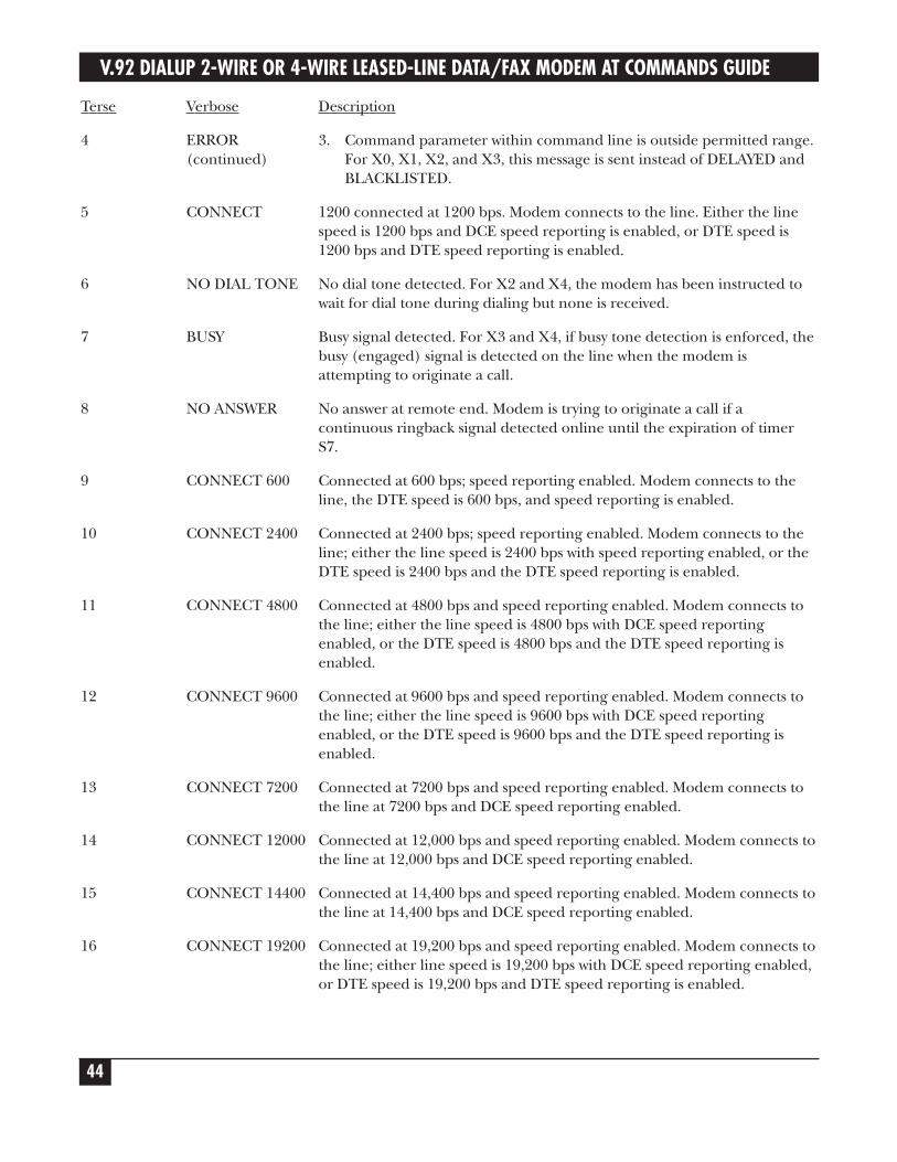
V.92 DIALUP 2-WIRE OR 4-WIRE LEASED-LINE DATA/FAX MODEM AT COMMANDS GUIDE
44
Terse Verbose Description
4 ERROR 3. Command parameter within command line is outside permitted range. (continued) For X0, X1, X2, and X3, this message is sent instead of DELAYED and
BLACKLISTED.
5 CONNECT 1200 connected at 1200 bps. Modem connects to the line. Either the linespeed is 1200 bps and DCE speed reporting is enabled, or DTE speed is1200 bps and DTE speed reporting is enabled.
6 NO DIAL TONE No dial tone detected. For X2 and X4, the modem has been instructed towait for dial tone during dialing but none is received.
7 BUSY Busy signal detected. For X3 and X4, if busy tone detection is enforced, thebusy (engaged) signal is detected on the line when the modem isattempting to originate a call.
8 NO ANSWER No answer at remote end. Modem is trying to originate a call if acontinuous ringback signal detected online until the expiration of timerS7.
9 CONNECT 600 Connected at 600 bps; speed reporting enabled. Modem connects to theline, the DTE speed is 600 bps, and speed reporting is enabled.
10 CONNECT 2400 Connected at 2400 bps; speed reporting enabled. Modem connects to theline; either the line speed is 2400 bps with speed reporting enabled, or theDTE speed is 2400 bps and the DTE speed reporting is enabled.
11 CONNECT 4800 Connected at 4800 bps and speed reporting enabled. Modem connects tothe line; either the line speed is 4800 bps with DCE speed reportingenabled, or the DTE speed is 4800 bps and the DTE speed reporting isenabled.
12 CONNECT 9600 Connected at 9600 bps and speed reporting enabled. Modem connects tothe line; either the line speed is 9600 bps with DCE speed reportingenabled, or the DTE speed is 9600 bps and the DTE speed reporting isenabled.
13 CONNECT 7200 Connected at 7200 bps and speed reporting enabled. Modem connects tothe line at 7200 bps and DCE speed reporting enabled.
14 CONNECT 12000 Connected at 12,000 bps and speed reporting enabled. Modem connects tothe line at 12,000 bps and DCE speed reporting enabled.
15 CONNECT 14400 Connected at 14,400 bps and speed reporting enabled. Modem connects tothe line at 14,400 bps and DCE speed reporting enabled.
16 CONNECT 19200 Connected at 19,200 bps and speed reporting enabled. Modem connects tothe line; either line speed is 19,200 bps with DCE speed reporting enabled,or DTE speed is 19,200 bps and DTE speed reporting is enabled.
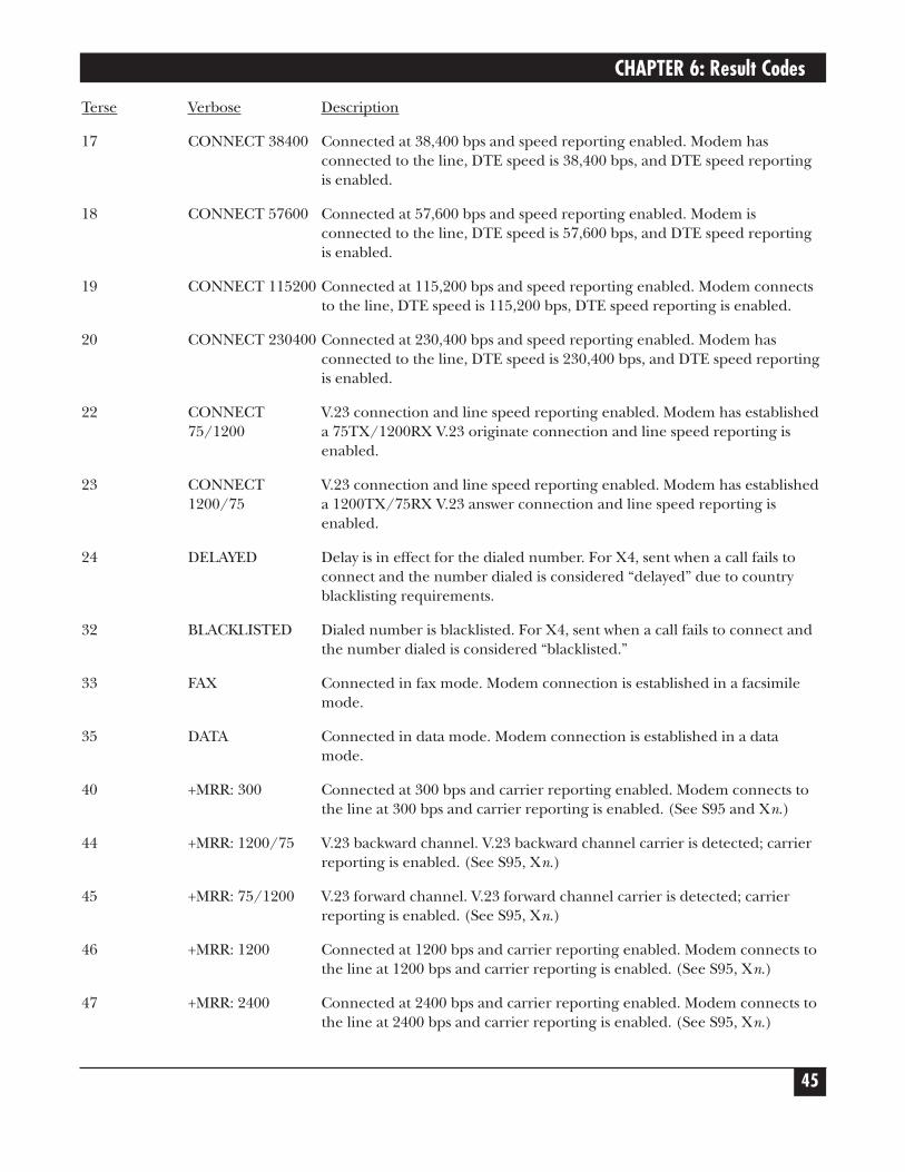
CHAPTER 6: Result Codes
45
Terse Verbose Description
17 CONNECT 38400 Connected at 38,400 bps and speed reporting enabled. Modem hasconnected to the line, DTE speed is 38,400 bps, and DTE speed reportingis enabled.
18 CONNECT 57600 Connected at 57,600 bps and speed reporting enabled. Modem isconnected to the line, DTE speed is 57,600 bps, and DTE speed reportingis enabled.
19 CONNECT 115200 Connected at 115,200 bps and speed reporting enabled. Modem connectsto the line, DTE speed is 115,200 bps, DTE speed reporting is enabled.
20 CONNECT 230400 Connected at 230,400 bps and speed reporting enabled. Modem hasconnected to the line, DTE speed is 230,400 bps, and DTE speed reportingis enabled.
22 CONNECT V.23 connection and line speed reporting enabled. Modem has established 75/1200 a 75TX/1200RX V.23 originate connection and line speed reporting is
enabled.
23 CONNECT V.23 connection and line speed reporting enabled. Modem has established 1200/75 a 1200TX/75RX V.23 answer connection and line speed reporting is
enabled.
24 DELAYED Delay is in effect for the dialed number. For X4, sent when a call fails toconnect and the number dialed is considered “delayed” due to countryblacklisting requirements.
32 BLACKLISTED Dialed number is blacklisted. For X4, sent when a call fails to connect andthe number dialed is considered “blacklisted.”
33 FAX Connected in fax mode. Modem connection is established in a facsimilemode.
35 DATA Connected in data mode. Modem connection is established in a datamode.
40 +MRR: 300 Connected at 300 bps and carrier reporting enabled. Modem connects tothe line at 300 bps and carrier reporting is enabled. (See S95 and Xn.)
44 +MRR: 1200/75 V.23 backward channel. V.23 backward channel carrier is detected; carrierreporting is enabled. (See S95, Xn.)
45 +MRR: 75/1200 V.23 forward channel. V.23 forward channel carrier is detected; carrierreporting is enabled. (See S95, Xn.)
46 +MRR: 1200 Connected at 1200 bps and carrier reporting enabled. Modem connects tothe line at 1200 bps and carrier reporting is enabled. (See S95, Xn.)
47 +MRR: 2400 Connected at 2400 bps and carrier reporting enabled. Modem connects tothe line at 2400 bps and carrier reporting is enabled. (See S95, Xn.)
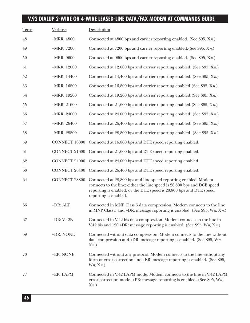
V.92 DIALUP 2-WIRE OR 4-WIRE LEASED-LINE DATA/FAX MODEM AT COMMANDS GUIDE
46
Terse Verbose Description
48 +MRR: 4800 Connected at 4800 bps and carrier reporting enabled. (See S95, Xn.)
49 +MRR: 7200 Connected at 7200 bps and carrier reporting enabled.(See S95, Xn.)
50 +MRR: 9600 Connected at 9600 bps and carrier reporting enabled. (See S95, Xn.)
51 +MRR: 12000 Connected at 12,000 bps and carrier reporting enabled. (See S95, Xn.)
52 +MRR: 14400 Connected at 14,400 bps and carrier reporting enabled. (See S95, Xn.)
53 +MRR: 16800 Connected at 16,800 bps and carrier reporting enabled.(See S95, Xn.)
54 +MRR: 19200 Connected at 19,200 bps and carrier reporting enabled.(See S95, Xn.)
55 +MRR: 21600 Connected at 21,600 bps and carrier reporting enabled.(See S95, Xn.)
56 +MRR: 24000 Connected at 24,000 bps and carrier reporting enabled. (See S95, Xn.)
57 +MRR: 26400 Connected at 26,400 bps and carrier reporting enabled. (See S95, Xn.)
58 +MRR: 28800 Connected at 28,800 bps and carrier reporting enabled. (See S95, Xn.)
59 CONNECT 16800 Connected at 16,800 bps and DTE speed reporting enabled.
61 CONNECT 21600 Connected at 21,600 bps and DTE speed reporting enabled.
62 CONNECT 24000 Connected at 24,000 bps and DTE speed reporting enabled.
63 CONNECT 26400 Connected at 26,400 bps and DTE speed reporting enabled.
64 CONNECT 28800 Connected at 28,800 bps and line speed reporting enabled. Modemconnects to the line; either the line speed is 28,800 bps and DCE speedreporting is enabled, or the DTE speed is 28,800 bps and DTE speedreporting is enabled.
66 +DR: ALT Connected in MNP Class 5 data compression. Modem connects to the linein MNP Class 5 and +DR: message reporting is enabled. (See S95, Wn, Xn.)
67 +DR: V.42B Connected in V.42 bis data compression. Modem connects to the line inV.42 bis and 120 +DR: message reporting is enabled. (See S95, Wn, Xn.)
69 +DR: NONE Connected without data compression. Modem connects to the line withoutdata compression and +DR: message reporting is enabled. (See S95, Wn,Xn.)
70 +ER: NONE Connected without any protocol. Modem connects to the line without anyform of error correction and +ER: message reporting is enabled. (See S95,Wn, Xn.)
77 +ER: LAPM Connected in V.42 LAPM mode. Modem connects to the line in V.42 LAPMerror correction mode. +ER: message reporting is enabled. (See S95, Wn,Xn.)
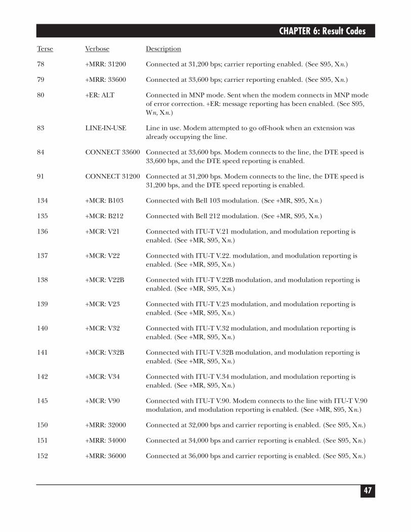
CHAPTER 6: Result Codes
47
Terse Verbose Description
78 +MRR: 31200 Connected at 31,200 bps; carrier reporting enabled. (See S95, Xn.)
79 +MRR: 33600 Connected at 33,600 bps; carrier reporting enabled. (See S95, Xn.)
80 +ER: ALT Connected in MNP mode. Sent when the modem connects in MNP modeof error correction. +ER: message reporting has been enabled. (See S95,Wn, Xn.)
83 LINE-IN-USE Line in use. Modem attempted to go off-hook when an extension wasalready occupying the line.
84 CONNECT 33600 Connected at 33,600 bps. Modem connects to the line, the DTE speed is33,600 bps, and the DTE speed reporting is enabled.
91 CONNECT 31200 Connected at 31,200 bps. Modem connects to the line, the DTE speed is31,200 bps, and the DTE speed reporting is enabled.
134 +MCR: B103 Connected with Bell 103 modulation. (See +MR, S95, Xn.)
135 +MCR: B212 Connected with Bell 212 modulation. (See +MR, S95, Xn.)
136 +MCR: V21 Connected with ITU-T V.21 modulation, and modulation reporting isenabled. (See +MR, S95, Xn.)
137 +MCR: V22 Connected with ITU-T V.22. modulation, and modulation reporting isenabled. (See +MR, S95, Xn.)
138 +MCR: V22B Connected with ITU-T V.22B modulation, and modulation reporting isenabled. (See +MR, S95, Xn.)
139 +MCR: V23 Connected with ITU-T V.23 modulation, and modulation reporting isenabled. (See +MR, S95, Xn.)
140 +MCR: V32 Connected with ITU-T V.32 modulation, and modulation reporting isenabled. (See +MR, S95, Xn.)
141 +MCR: V32B Connected with ITU-T V.32B modulation, and modulation reporting isenabled. (See +MR, S95, Xn.)
142 +MCR: V34 Connected with ITU-T V.34 modulation, and modulation reporting isenabled. (See +MR, S95, Xn.)
145 +MCR: V90 Connected with ITU-T V.90. Modem connects to the line with ITU-T V.90modulation, and modulation reporting is enabled. (See +MR, S95, Xn.)
150 +MRR: 32000 Connected at 32,000 bps and carrier reporting is enabled. (See S95, Xn.)
151 +MRR: 34000 Connected at 34,000 bps and carrier reporting is enabled. (See S95, Xn.)
152 +MRR: 36000 Connected at 36,000 bps and carrier reporting is enabled. (See S95, Xn.)
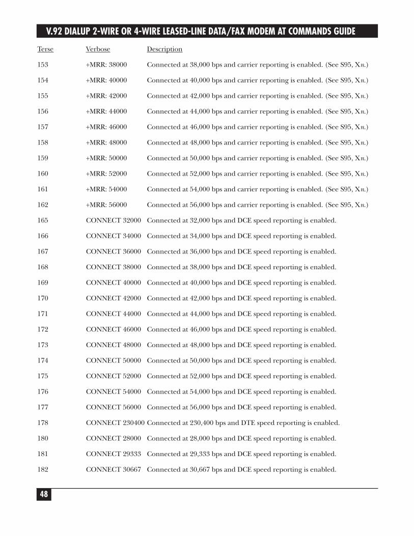
V.92 DIALUP 2-WIRE OR 4-WIRE LEASED-LINE DATA/FAX MODEM AT COMMANDS GUIDE
48
Terse Verbose Description
153 +MRR: 38000 Connected at 38,000 bps and carrier reporting is enabled. (See S95, Xn.)
154 +MRR: 40000 Connected at 40,000 bps and carrier reporting is enabled. (See S95, Xn.)
155 +MRR: 42000 Connected at 42,000 bps and carrier reporting is enabled. (See S95, Xn.)
156 +MRR: 44000 Connected at 44,000 bps and carrier reporting is enabled. (See S95, Xn.)
157 +MRR: 46000 Connected at 46,000 bps and carrier reporting is enabled. (See S95, Xn.)
158 +MRR: 48000 Connected at 48,000 bps and carrier reporting is enabled. (See S95, Xn.)
159 +MRR: 50000 Connected at 50,000 bps and carrier reporting is enabled. (See S95, Xn.)
160 +MRR: 52000 Connected at 52,000 bps and carrier reporting is enabled. (See S95, Xn.)
161 +MRR: 54000 Connected at 54,000 bps and carrier reporting is enabled. (See S95, Xn.)
162 +MRR: 56000 Connected at 56,000 bps and carrier reporting is enabled. (See S95, Xn.)
165 CONNECT 32000 Connected at 32,000 bps and DCE speed reporting is enabled.
166 CONNECT 34000 Connected at 34,000 bps and DCE speed reporting is enabled.
167 CONNECT 36000 Connected at 36,000 bps and DCE speed reporting is enabled.
168 CONNECT 38000 Connected at 38,000 bps and DCE speed reporting is enabled.
169 CONNECT 40000 Connected at 40,000 bps and DCE speed reporting is enabled.
170 CONNECT 42000 Connected at 42,000 bps and DCE speed reporting is enabled.
171 CONNECT 44000 Connected at 44,000 bps and DCE speed reporting is enabled.
172 CONNECT 46000 Connected at 46,000 bps and DCE speed reporting is enabled.
173 CONNECT 48000 Connected at 48,000 bps and DCE speed reporting is enabled.
174 CONNECT 50000 Connected at 50,000 bps and DCE speed reporting is enabled.
175 CONNECT 52000 Connected at 52,000 bps and DCE speed reporting is enabled.
176 CONNECT 54000 Connected at 54,000 bps and DCE speed reporting is enabled.
177 CONNECT 56000 Connected at 56,000 bps and DCE speed reporting is enabled.
178 CONNECT 230400 Connected at 230,400 bps and DTE speed reporting is enabled.
180 CONNECT 28000 Connected at 28,000 bps and DCE speed reporting is enabled.
181 CONNECT 29333 Connected at 29,333 bps and DCE speed reporting is enabled.
182 CONNECT 30667 Connected at 30,667 bps and DCE speed reporting is enabled.
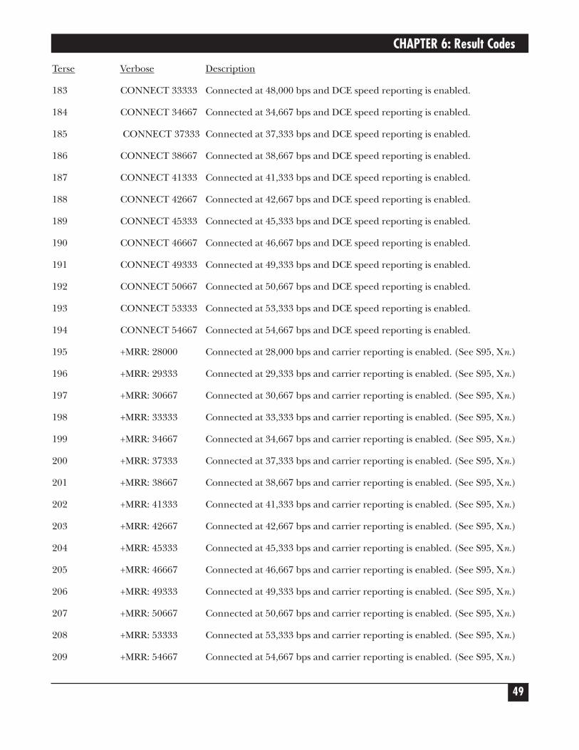
CHAPTER 6: Result Codes
49
Terse Verbose Description
183 CONNECT 33333 Connected at 48,000 bps and DCE speed reporting is enabled.
184 CONNECT 34667 Connected at 34,667 bps and DCE speed reporting is enabled.
185 CONNECT 37333 Connected at 37,333 bps and DCE speed reporting is enabled.
186 CONNECT 38667 Connected at 38,667 bps and DCE speed reporting is enabled.
187 CONNECT 41333 Connected at 41,333 bps and DCE speed reporting is enabled.
188 CONNECT 42667 Connected at 42,667 bps and DCE speed reporting is enabled.
189 CONNECT 45333 Connected at 45,333 bps and DCE speed reporting is enabled.
190 CONNECT 46667 Connected at 46,667 bps and DCE speed reporting is enabled.
191 CONNECT 49333 Connected at 49,333 bps and DCE speed reporting is enabled.
192 CONNECT 50667 Connected at 50,667 bps and DCE speed reporting is enabled.
193 CONNECT 53333 Connected at 53,333 bps and DCE speed reporting is enabled.
194 CONNECT 54667 Connected at 54,667 bps and DCE speed reporting is enabled.
195 +MRR: 28000 Connected at 28,000 bps and carrier reporting is enabled. (See S95, Xn.)
196 +MRR: 29333 Connected at 29,333 bps and carrier reporting is enabled. (See S95, Xn.)
197 +MRR: 30667 Connected at 30,667 bps and carrier reporting is enabled. (See S95, Xn.)
198 +MRR: 33333 Connected at 33,333 bps and carrier reporting is enabled. (See S95, Xn.)
199 +MRR: 34667 Connected at 34,667 bps and carrier reporting is enabled. (See S95, Xn.)
200 +MRR: 37333 Connected at 37,333 bps and carrier reporting is enabled. (See S95, Xn.)
201 +MRR: 38667 Connected at 38,667 bps and carrier reporting is enabled. (See S95, Xn.)
202 +MRR: 41333 Connected at 41,333 bps and carrier reporting is enabled. (See S95, Xn.)
203 +MRR: 42667 Connected at 42,667 bps and carrier reporting is enabled. (See S95, Xn.)
204 +MRR: 45333 Connected at 45,333 bps and carrier reporting is enabled. (See S95, Xn.)
205 +MRR: 46667 Connected at 46,667 bps and carrier reporting is enabled. (See S95, Xn.)
206 +MRR: 49333 Connected at 49,333 bps and carrier reporting is enabled. (See S95, Xn.)
207 +MRR: 50667 Connected at 50,667 bps and carrier reporting is enabled. (See S95, Xn.)
208 +MRR: 53333 Connected at 53,333 bps and carrier reporting is enabled. (See S95, Xn.)
209 +MRR: 54667 Connected at 54,667 bps and carrier reporting is enabled. (See S95, Xn.)
V.92 DIALUP 2-WIRE OR 4-WIRE LEASED-LINE DATA/FAX MODEM AT COMMANDS GUIDE
50
NOTES1. See Vn for result code selection; that is, short form (result code) or
verbose/extended (result message).2. See Wn for extended connect message control.3. See S95 for extended result code enabling options (which override some Wn
commands).4. See Xn for extended result code subset enabling options.5. See \Vn for single line connect message enable options.6. See +MR for modulation reporting control.
51
7. Setting Country/Regional CodesCountries or regions vary in their requirements for how a modem functions. Therefore, you must configureyour modem to match the defaults of your country or region. Choose from any of the three methods:
• Using the LCD panel to set your country or region code.
• Using the global wizard to set your country or region code.
• Using AT commands to set your country or region code.
7.1 Using the LCD Panel1. Start at the Status LCD and use ↓ to move down the menu tree to the Region Select LCD.
2. Use → to move from the Region Select LCD across the Region Settings Options LCD to the CurrentSetting LCD.
3. If the current setting shown is not the one for your region, use the arrow keys to get to the Region ProfileLCD. The question mark represents the question: Is this the region you want? If B5 is the one you want,press Enter; if it’s not the one you want, use the arrow keys to get to the code you want. The region codefor Japan is 00.
4. When you reach the region code you want, press Enter. You will then see the message Option Set.
5. After setting the region profile, you can cycle the power to the modem (turn it off and then back onagain) or use the arrows to move back and up the menu tree to return to the Status LCD.
CHAPTER 7: Setting Country/Regional Codes
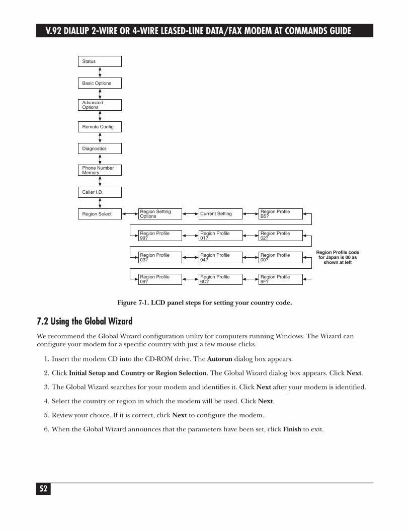
V.92 DIALUP 2-WIRE OR 4-WIRE LEASED-LINE DATA/FAX MODEM AT COMMANDS GUIDE
52
Figure 7-1. LCD panel steps for setting your country code.
7.2 Using the Global WizardWe recommend the Global Wizard configuration utility for computers running Windows. The Wizard canconfigure your modem for a specific country with just a few mouse clicks.
1. Insert the modem CD into the CD-ROM drive. The Autorun dialog box appears.
2. Click Initial Setup and Country or Region Selection. The Global Wizard dialog box appears. Click Next.
3. The Global Wizard searches for your modem and identifies it. Click Next after your modem is identified.
4. Select the country or region in which the modem will be used. Click Next.
5. Review your choice. If it is correct, click Next to configure the modem.
6. When the Global Wizard announces that the parameters have been set, click Finish to exit.
Region Profile codefor Japan is 00 as
shown at left
CHAPTER 7: Setting Country/Regional Codes
53
7.3 Using AT CommandsIf you are comfortable using AT commands, you can use them to configure your modem. You must enter thesecommands in your communication program’s terminal window. You can use a communication program such asPhoneTools.
How to change the country/region code
1. Set and save the country/region code (00) by typing the command AT+GCI=00<CR>.
2. An OK message displays onscreen.
3. The code 00 appears onscreen.
How to verify the code
Type AT +GCI?<CR> or use the command AT+00<CR>.

6-1-1 Heiwajima, Ota-ku, Tokyo, 143-6501, Japan • 03-5471-8800 • Fax 03-5471-8822
© Copyright 2006. Black Box Corporation. All rights reserved.


![Estimation and postestimation commands - Stata · PDF file2[U] 20 Estimation and postestimation commands 20.1 All estimation commands work the same way All Stata commands that fit](https://img.pdfslide.us/doc/110x75/5aa93f287f8b9a8b188c9cec/estimation-and-postestimation-commands-stata-u-20-estimation-and-postestimation.jpg)