Embed Size (px)
Citation preview
CUSTOMERSUPPORT
INFORMATION
Order toll-free in the U.S. 24 hours, 7 A.M. Monday to midnight Friday: 877-877-BBOXFREE technical support, 24 hours a day, 7 days a week: Call 724-746-5500 or fax 724-746-0746Mail order: Black Box Corporation, 1000 Park Drive, Lawrence, PA 15055-1018Web site: www.blackbox.com • E-mail: [email protected]
SEPTEMBER 1999TS6000A
TS6000AETS6001A
TS691TS692TS693TS694
SCAN-LAN VI
F1F2
F3F4
ESC
ENTER
AUTOTEST
REMOTE
CAL
SETUP
TRAFFIC
LENGTH
WIRE
MAP
QUICK √
SCAN-LAN VI
EXTENDED
FUNCTIONS

1
FCC STATEMENT
FEDERAL COMMUNICATIONS COMMISSIONAND
INDUSTRY CANADARADIO FREQUENCY INTERFERENCE STATEMENTS
This equipment generates, uses, and can radiate radio frequency energy and if notinstalled and used properly, that is, in strict accordance with the manufacturer’sinstructions, may cause interference to radio communication. It has been testedand found to comply with the limits for a Class A computing device in accordancewith the specifications in Subpart J of Part 15 of FCC rules, which are designed toprovide reasonable protection against such interference when the equipment isoperated in a commercial environment. Operation of this equipment in aresidential area is likely to cause interference, in which case the user at his ownexpense will be required to take whatever measures may be necessary to correct the interference.
Changes or modifications not expressly approved by the party responsible for compliance could void the user’s authority to operate the equipment.
This digital apparatus does not exceed the Class A limits for radio noise emission from digital apparatus set out in the Radio Interference Regulation of Industry Canada.
Le présent appareil numérique n’émet pas de bruits radioélectriques dépassant les limitesapplicables aux appareils numériques de la classe A prescrites dans le Règlement sur lebrouillage radioélectrique publié par Industrie Canada.
2
SCAN-LAN VI
NORMAS OFICIALES MEXICANAS (NOM)ELECTRICAL SAFETY STATEMENT
INSTRUCCIONES DE SEGURIDAD
1. Todas las instrucciones de seguridad y operación deberán ser leídas antes de que el aparato eléctrico sea operado.
2. Las instrucciones de seguridad y operación deberán ser guardadas parareferencia futura.
3. Todas las advertencias en el aparato eléctrico y en sus instrucciones deoperación deben ser respetadas.
4. Todas las instrucciones de operación y uso deben ser seguidas.
5. El aparato eléctrico no deberá ser usado cerca del agua—por ejemplo, cercade la tina de baño, lavabo, sótano mojado o cerca de una alberca, etc..
6. El aparato eléctrico debe ser usado únicamente con carritos o pedestales que sean recomendados por el fabricante.
7. El aparato eléctrico debe ser montado a la pared o al techo sólo como searecomendado por el fabricante.
8. Servicio—El usuario no debe intentar dar servicio al equipo eléctrico más alláa lo descrito en las instrucciones de operación. Todo otro servicio deberá serreferido a personal de servicio calificado.
9. El aparato eléctrico debe ser situado de tal manera que su posición nointerfiera su uso. La colocación del aparato eléctrico sobre una cama, sofá,alfombra o superficie similar puede bloquea la ventilación, no se debe colocaren libreros o gabinetes que impidan el flujo de aire por los orificios deventilación.
10. El equipo eléctrico deber ser situado fuera del alcance de fuentes de calorcomo radiadores, registros de calor, estufas u otros aparatos (incluyendoamplificadores) que producen calor.
11. El aparato eléctrico deberá ser connectado a una fuente de poder sólo deltipo descrito en el instructivo de operación, o como se indique en el aparato.
3
NOM STATEMENT
12. Precaución debe ser tomada de tal manera que la tierra fisica y la polarizacióndel equipo no sea eliminada.
13. Los cables de la fuente de poder deben ser guiados de tal manera que nosean pisados ni pellizcados por objetos colocados sobre o contra ellos,poniendo particular atención a los contactos y receptáculos donde salen del aparato.
14. El equipo eléctrico debe ser limpiado únicamente de acuerdo a lasrecomendaciones del fabricante.
15. En caso de existir, una antena externa deberá ser localizada lejos de las lineas de energia.
16. El cable de corriente deberá ser desconectado del cuando el equipo no sea usado por un largo periodo de tiempo.
17. Cuidado debe ser tomado de tal manera que objectos liquidos no sean derramados sobre la cubierta u orificios de ventilación.
18. Servicio por personal calificado deberá ser provisto cuando:
A: El cable de poder o el contacto ha sido dañado; u
B: Objectos han caído o líquido ha sido derramado dentro del aparato; o
C: El aparato ha sido expuesto a la lluvia; o
D: El aparato parece no operar normalmente o muestra un cambio en su desempeño; o
E: El aparato ha sido tirado o su cubierta ha sido dañada.

4
SCAN-LAN VI
TRADEMARKS
The trademarks mentioned in this manual are acknowledged to be the property of the trademark owners.
5
CONTENTS
ContentsChapter Page
1. Specifications . . . . . . . . . . . . . . . . . . . . . . . . . . . . . . . . . . . . . . . . . . . . . . . . . . . . . 10
2. Introduction . . . . . . . . . . . . . . . . . . . . . . . . . . . . . . . . . . . . . . . . . . . . . . . . . . . . . . 142.1 Packing List . . . . . . . . . . . . . . . . . . . . . . . . . . . . . . . . . . . . . . . . . . . . . . . . . . . . 152.2 Features . . . . . . . . . . . . . . . . . . . . . . . . . . . . . . . . . . . . . . . . . . . . . . . . . . . . . . . 15
2.2.1 Testing Features . . . . . . . . . . . . . . . . . . . . . . . . . . . . . . . . . . . . . . . . . . . . 152.2.2 Cable Standards Supported to 250 MHz . . . . . . . . . . . . . . . . . . . . . . . . 162.2.3 Network Standards Supported at 250 MHz . . . . . . . . . . . . . . . . . . . . . . 162.2.4 Special Features of the SCAN-LAN VI . . . . . . . . . . . . . . . . . . . . . . . . . . 162.2.5 Send Function . . . . . . . . . . . . . . . . . . . . . . . . . . . . . . . . . . . . . . . . . . . . . 192.2.6 LinkTalk Function . . . . . . . . . . . . . . . . . . . . . . . . . . . . . . . . . . . . . . . . . . 192.2.7 Performance Module. . . . . . . . . . . . . . . . . . . . . . . . . . . . . . . . . . . . . . . . 19
2.3 Battery Information . . . . . . . . . . . . . . . . . . . . . . . . . . . . . . . . . . . . . . . . . . . . . 202.3.1 Memory Storage . . . . . . . . . . . . . . . . . . . . . . . . . . . . . . . . . . . . . . . . . . . . 202.3.2 Charging Mode . . . . . . . . . . . . . . . . . . . . . . . . . . . . . . . . . . . . . . . . . . . . 202.3.3 Charging the Batteries . . . . . . . . . . . . . . . . . . . . . . . . . . . . . . . . . . . . . . . 212.3.4 Using the Rechargeable Battery Eliminator . . . . . . . . . . . . . . . . . . . . . 21
2.4 Display Conventions . . . . . . . . . . . . . . . . . . . . . . . . . . . . . . . . . . . . . . . . . . . . . 222.4.1 Arrow Keys . . . . . . . . . . . . . . . . . . . . . . . . . . . . . . . . . . . . . . . . . . . . . . . . 222.4.2 Scroll Bars . . . . . . . . . . . . . . . . . . . . . . . . . . . . . . . . . . . . . . . . . . . . . . . . . 232.4.3 Display Contrast Adjustment. . . . . . . . . . . . . . . . . . . . . . . . . . . . . . . . . . 23
3. Getting Started . . . . . . . . . . . . . . . . . . . . . . . . . . . . . . . . . . . . . . . . . . . . . . . . . . . . 243.1 Initial Setup . . . . . . . . . . . . . . . . . . . . . . . . . . . . . . . . . . . . . . . . . . . . . . . . . . . . 24
3.1.1 Setting Up the SCAN-LAN VI . . . . . . . . . . . . . . . . . . . . . . . . . . . . . . . . . 243.1.2 NVP Calibration . . . . . . . . . . . . . . . . . . . . . . . . . . . . . . . . . . . . . . . . . . . . 253.1.3 Why Do I Need to Set Cable NVP? . . . . . . . . . . . . . . . . . . . . . . . . . . . . . 25
3.2 Typical Test Setup. . . . . . . . . . . . . . . . . . . . . . . . . . . . . . . . . . . . . . . . . . . . . . . 263.2.1 Basic-Link Testing . . . . . . . . . . . . . . . . . . . . . . . . . . . . . . . . . . . . . . . . . . 263.2.2 Channel Testing. . . . . . . . . . . . . . . . . . . . . . . . . . . . . . . . . . . . . . . . . . . . 27
3.3 Selecting a Cable Test Standard . . . . . . . . . . . . . . . . . . . . . . . . . . . . . . . . . . . 273.4 Defining Custom Standards . . . . . . . . . . . . . . . . . . . . . . . . . . . . . . . . . . . . . . . 283.5 System Integrity Pre-Test . . . . . . . . . . . . . . . . . . . . . . . . . . . . . . . . . . . . . . . . . 30
4. Autotest . . . . . . . . . . . . . . . . . . . . . . . . . . . . . . . . . . . . . . . . . . . . . . . . . . . . . . . . . . 314.1 Running Autotest . . . . . . . . . . . . . . . . . . . . . . . . . . . . . . . . . . . . . . . . . . . . . . . 314.2 Viewing Autotest Results. . . . . . . . . . . . . . . . . . . . . . . . . . . . . . . . . . . . . . . . . . 32
4.2.1 Summary Results . . . . . . . . . . . . . . . . . . . . . . . . . . . . . . . . . . . . . . . . . . . 33
6
SCAN-LAN VI
Chapter Page
4.2.2 Marginal Test Results. . . . . . . . . . . . . . . . . . . . . . . . . . . . . . . . . . . . . . . . 334.2.3 Detailed Results . . . . . . . . . . . . . . . . . . . . . . . . . . . . . . . . . . . . . . . . . . . . 34
4.3 Viewing 250 MHz Autotest Results . . . . . . . . . . . . . . . . . . . . . . . . . . . . . . . . . 344.3.1 Link Performance Screen . . . . . . . . . . . . . . . . . . . . . . . . . . . . . . . . . . . . 354.3.2 Power Sum ACR . . . . . . . . . . . . . . . . . . . . . . . . . . . . . . . . . . . . . . . . . . . . 35
4.4 Saving Autotest Results . . . . . . . . . . . . . . . . . . . . . . . . . . . . . . . . . . . . . . . . . . . 364.5 LinkTalk. . . . . . . . . . . . . . . . . . . . . . . . . . . . . . . . . . . . . . . . . . . . . . . . . . . . . . . 38
4.5.1 Interaction of Talk and Send Functions . . . . . . . . . . . . . . . . . . . . . . . . 394.5.2 System Integrity Pre-Test . . . . . . . . . . . . . . . . . . . . . . . . . . . . . . . . . . . . . 40
5. Quick Check . . . . . . . . . . . . . . . . . . . . . . . . . . . . . . . . . . . . . . . . . . . . . . . . . . . . . . 415.1 Running Quick Check . . . . . . . . . . . . . . . . . . . . . . . . . . . . . . . . . . . . . . . . . . . 415.2 Viewing Quick Check Results. . . . . . . . . . . . . . . . . . . . . . . . . . . . . . . . . . . . . . 41
6. Cable Test Descriptions . . . . . . . . . . . . . . . . . . . . . . . . . . . . . . . . . . . . . . . . . . . . . 436.1 Wire Map . . . . . . . . . . . . . . . . . . . . . . . . . . . . . . . . . . . . . . . . . . . . . . . . . . . . . . 43
6.1.1 Running Wire Map . . . . . . . . . . . . . . . . . . . . . . . . . . . . . . . . . . . . . . . . . 436.1.2 Viewing Wire Map Results . . . . . . . . . . . . . . . . . . . . . . . . . . . . . . . . . . . . 44
6.2 NEXT . . . . . . . . . . . . . . . . . . . . . . . . . . . . . . . . . . . . . . . . . . . . . . . . . . . . . . . . . 456.2.1 Running NEXT . . . . . . . . . . . . . . . . . . . . . . . . . . . . . . . . . . . . . . . . . . . . 456.2.2 Viewing NEXT Summary Results . . . . . . . . . . . . . . . . . . . . . . . . . . . . . . 466.2.3 Marginal Test Results. . . . . . . . . . . . . . . . . . . . . . . . . . . . . . . . . . . . . . . . 466.2.4 Viewing Detailed NEXT Results . . . . . . . . . . . . . . . . . . . . . . . . . . . . . . . 466.2.5 Viewing a Graph of NEXT Results . . . . . . . . . . . . . . . . . . . . . . . . . . . . . 476.2.6 Certifying Category 5 Cabling—Pair-to-Pair NEXT Method . . . . . . . . 48
6.3 Length . . . . . . . . . . . . . . . . . . . . . . . . . . . . . . . . . . . . . . . . . . . . . . . . . . . . . . . . 486.3.1 Running Length Test. . . . . . . . . . . . . . . . . . . . . . . . . . . . . . . . . . . . . . . . 496.3.2 Viewing Length Results . . . . . . . . . . . . . . . . . . . . . . . . . . . . . . . . . . . . . . 49
6.4 Attenuation . . . . . . . . . . . . . . . . . . . . . . . . . . . . . . . . . . . . . . . . . . . . . . . . . . . . 516.4.1 Running Attenuation. . . . . . . . . . . . . . . . . . . . . . . . . . . . . . . . . . . . . . . . 526.4.2 Viewing Attenuation Results . . . . . . . . . . . . . . . . . . . . . . . . . . . . . . . . . . 526.4.3 Viewing a Graph of Attenuation Results . . . . . . . . . . . . . . . . . . . . . . . . 536.4.4 Marginal Test Results. . . . . . . . . . . . . . . . . . . . . . . . . . . . . . . . . . . . . . . . 53
6.5 ACR . . . . . . . . . . . . . . . . . . . . . . . . . . . . . . . . . . . . . . . . . . . . . . . . . . . . . . . . . . 546.5.1 Running ACR . . . . . . . . . . . . . . . . . . . . . . . . . . . . . . . . . . . . . . . . . . . . . . 546.5.2 Viewing ACR Results . . . . . . . . . . . . . . . . . . . . . . . . . . . . . . . . . . . . . . . . 546.5.3 Link Performance Analysis Beyond 100 MHz—
ACR and Headroom . . . . . . . . . . . . . . . . . . . . . . . . . . . . . . . . . . . . . . . . 556.6 Noise . . . . . . . . . . . . . . . . . . . . . . . . . . . . . . . . . . . . . . . . . . . . . . . . . . . . . . . . . 56
6.6.1 Running Noise . . . . . . . . . . . . . . . . . . . . . . . . . . . . . . . . . . . . . . . . . . . . . 566.6.2 Viewing Noise Results . . . . . . . . . . . . . . . . . . . . . . . . . . . . . . . . . . . . . . . 57
7
CONTENTS
Chapter Page
6.7 Pair Reversal Test . . . . . . . . . . . . . . . . . . . . . . . . . . . . . . . . . . . . . . . . . . . . . . . 576.8 Repeatability Test . . . . . . . . . . . . . . . . . . . . . . . . . . . . . . . . . . . . . . . . . . . . . . . 586.9 Impedance. . . . . . . . . . . . . . . . . . . . . . . . . . . . . . . . . . . . . . . . . . . . . . . . . . . . . 596.10 Cable Toner. . . . . . . . . . . . . . . . . . . . . . . . . . . . . . . . . . . . . . . . . . . . . . . . . . . 596.11 Delay/Delay Skew . . . . . . . . . . . . . . . . . . . . . . . . . . . . . . . . . . . . . . . . . . . . . . 606.12 Resistance . . . . . . . . . . . . . . . . . . . . . . . . . . . . . . . . . . . . . . . . . . . . . . . . . . . . 62
6.12.1 Running Resistance . . . . . . . . . . . . . . . . . . . . . . . . . . . . . . . . . . . . . . . . 626.12.2 Viewing Resistance Results . . . . . . . . . . . . . . . . . . . . . . . . . . . . . . . . . . 63
6.13 Power Sum NEXT. . . . . . . . . . . . . . . . . . . . . . . . . . . . . . . . . . . . . . . . . . . . . . 636.13.1 Viewing Power Sum NEXT Results. . . . . . . . . . . . . . . . . . . . . . . . . . . . 646.13.2 Viewing a Graph of Power Sum NEXT Results . . . . . . . . . . . . . . . . . . 66
6.14 Cable Grading . . . . . . . . . . . . . . . . . . . . . . . . . . . . . . . . . . . . . . . . . . . . . . . . . 67
7. Printing, Uploading, and Viewing Test Results . . . . . . . . . . . . . . . . . . . . . . . . . . 687.1 Connecting to a PC or Printer . . . . . . . . . . . . . . . . . . . . . . . . . . . . . . . . . . . . . 68
7.1.1 Overview . . . . . . . . . . . . . . . . . . . . . . . . . . . . . . . . . . . . . . . . . . . . . . . . . . 687.1.2 Adapter/Connector Information . . . . . . . . . . . . . . . . . . . . . . . . . . . . . . 68
7.2 Printing/Uploading Test Results. . . . . . . . . . . . . . . . . . . . . . . . . . . . . . . . . . . 687.2.1 Printing/Uploading a Single Test Report . . . . . . . . . . . . . . . . . . . . . . . 687.2.2 Printing/Uploading Multiple Reports . . . . . . . . . . . . . . . . . . . . . . . . . . 697.2.3 Printing/Uploading All Reports . . . . . . . . . . . . . . . . . . . . . . . . . . . . . . . 707.2.4 Uploading Detailed NEXT/Attenuation Results . . . . . . . . . . . . . . . . . 707.2.5 Changing Serial-Port Settings . . . . . . . . . . . . . . . . . . . . . . . . . . . . . . . . . 717.2.6 Sample 250 MHz UTP Autotest Report . . . . . . . . . . . . . . . . . . . . . . . . . 72
7.3 Deleting Test Reports . . . . . . . . . . . . . . . . . . . . . . . . . . . . . . . . . . . . . . . . . . . . 747.4 Viewing Saved Test Reports . . . . . . . . . . . . . . . . . . . . . . . . . . . . . . . . . . . . . . . 74
8. Testing Twisted-Pair Cable. . . . . . . . . . . . . . . . . . . . . . . . . . . . . . . . . . . . . . . . . . . 778.1 Types of Twisted-Pair Cable . . . . . . . . . . . . . . . . . . . . . . . . . . . . . . . . . . . . . . . 778.2 Twisted-Pair Test Descriptions . . . . . . . . . . . . . . . . . . . . . . . . . . . . . . . . . . . . . 78
8.2.1 Wire Map . . . . . . . . . . . . . . . . . . . . . . . . . . . . . . . . . . . . . . . . . . . . . . . . . 788.2.2 Near-End Crosstalk (NEXT) . . . . . . . . . . . . . . . . . . . . . . . . . . . . . . . . . . 838.2.3 Attenuation. . . . . . . . . . . . . . . . . . . . . . . . . . . . . . . . . . . . . . . . . . . . . . . . 888.2.4 Length. . . . . . . . . . . . . . . . . . . . . . . . . . . . . . . . . . . . . . . . . . . . . . . . . . . . 908.2.5 Noise . . . . . . . . . . . . . . . . . . . . . . . . . . . . . . . . . . . . . . . . . . . . . . . . . . . . . 958.2.6 Impedance . . . . . . . . . . . . . . . . . . . . . . . . . . . . . . . . . . . . . . . . . . . . . . . . 968.2.7 Resistance . . . . . . . . . . . . . . . . . . . . . . . . . . . . . . . . . . . . . . . . . . . . . . . . . 96
8.3 Testing Tips . . . . . . . . . . . . . . . . . . . . . . . . . . . . . . . . . . . . . . . . . . . . . . . . . . . . 978.3.1 Selecting Performance Module (PM) and
Cable Specification. . . . . . . . . . . . . . . . . . . . . . . . . . . . . . . . . . . . . . . . . . 978.3.2 Connecting the Segment Under Test. . . . . . . . . . . . . . . . . . . . . . . . . . . 97
8
SCAN-LAN VI
Chapter Page
8.3.3 Selecting the Proper Test . . . . . . . . . . . . . . . . . . . . . . . . . . . . . . . . . . . . 988.3.4 Interpreting Results . . . . . . . . . . . . . . . . . . . . . . . . . . . . . . . . . . . . . . . . . 98
8.4 Power Sum NEXT . . . . . . . . . . . . . . . . . . . . . . . . . . . . . . . . . . . . . . . . . . . . . . . 998.5 Delay/Delay Skew . . . . . . . . . . . . . . . . . . . . . . . . . . . . . . . . . . . . . . . . . . . . . . 101
9. Setup . . . . . . . . . . . . . . . . . . . . . . . . . . . . . . . . . . . . . . . . . . . . . . . . . . . . . . . . . . . 1029.1 Setup Functions. . . . . . . . . . . . . . . . . . . . . . . . . . . . . . . . . . . . . . . . . . . . . . . . 1029.2 Changing Setup Parameters. . . . . . . . . . . . . . . . . . . . . . . . . . . . . . . . . . . . . . 103
9.2.1 Length Measurement Units . . . . . . . . . . . . . . . . . . . . . . . . . . . . . . . . . 1039.2.2 Fault Threshold . . . . . . . . . . . . . . . . . . . . . . . . . . . . . . . . . . . . . . . . . . . 1039.2.3 Noise Threshold. . . . . . . . . . . . . . . . . . . . . . . . . . . . . . . . . . . . . . . . . . . 1049.2.4 Power Down Time . . . . . . . . . . . . . . . . . . . . . . . . . . . . . . . . . . . . . . . . . 1059.2.5 Backlight Time . . . . . . . . . . . . . . . . . . . . . . . . . . . . . . . . . . . . . . . . . . . . 1059.2.6 Power Frequency . . . . . . . . . . . . . . . . . . . . . . . . . . . . . . . . . . . . . . . . . . 1069.2.7 Baud Rate . . . . . . . . . . . . . . . . . . . . . . . . . . . . . . . . . . . . . . . . . . . . . . . . 1079.2.8 Flow Control . . . . . . . . . . . . . . . . . . . . . . . . . . . . . . . . . . . . . . . . . . . . . . 1079.2.9 Date . . . . . . . . . . . . . . . . . . . . . . . . . . . . . . . . . . . . . . . . . . . . . . . . . . . . . 1089.2.10 Time . . . . . . . . . . . . . . . . . . . . . . . . . . . . . . . . . . . . . . . . . . . . . . . . . . . 1089.2.11 Audible Tones . . . . . . . . . . . . . . . . . . . . . . . . . . . . . . . . . . . . . . . . . . . 1099.2.12 Traffic/Noise Tones . . . . . . . . . . . . . . . . . . . . . . . . . . . . . . . . . . . . . . 1099.2.13 Company Name . . . . . . . . . . . . . . . . . . . . . . . . . . . . . . . . . . . . . . . . . . 1109.2.14 Circuit Names. . . . . . . . . . . . . . . . . . . . . . . . . . . . . . . . . . . . . . . . . . . . 1119.2.15 Auto Toner . . . . . . . . . . . . . . . . . . . . . . . . . . . . . . . . . . . . . . . . . . . . . . 1129.2.16 Reset to Defaults. . . . . . . . . . . . . . . . . . . . . . . . . . . . . . . . . . . . . . . . . . 1129.2.17 Circuit Names. . . . . . . . . . . . . . . . . . . . . . . . . . . . . . . . . . . . . . . . . . . . 113
10. Calibration. . . . . . . . . . . . . . . . . . . . . . . . . . . . . . . . . . . . . . . . . . . . . . . . . . . . . . 11510.1 NVP Calibration . . . . . . . . . . . . . . . . . . . . . . . . . . . . . . . . . . . . . . . . . . . . . . 115
10.1.1 Using a Known Length of Cable . . . . . . . . . . . . . . . . . . . . . . . . . . . . . 11510.1.2 Using Manufacturer’s Cable Specifications . . . . . . . . . . . . . . . . . . . . 11610.1.3 Why Do I Need to Set Cable NVP? . . . . . . . . . . . . . . . . . . . . . . . . . . . 117
10.2 Remote-Unit Calibration . . . . . . . . . . . . . . . . . . . . . . . . . . . . . . . . . . . . . . . 11710.3 Performance-Module Calibration . . . . . . . . . . . . . . . . . . . . . . . . . . . . . . . . 11810.4 Impedance Calibration. . . . . . . . . . . . . . . . . . . . . . . . . . . . . . . . . . . . . . . . . 12010.5 Resistance Calibration . . . . . . . . . . . . . . . . . . . . . . . . . . . . . . . . . . . . . . . . . 12010.6 Main-Unit Calibration . . . . . . . . . . . . . . . . . . . . . . . . . . . . . . . . . . . . . . . . . 120
11. Ethernet Traffic Analysis . . . . . . . . . . . . . . . . . . . . . . . . . . . . . . . . . . . . . . . . . . 12111.1 Running the Traffic Test . . . . . . . . . . . . . . . . . . . . . . . . . . . . . . . . . . . . . . . 12111.2 Viewing Traffic Results . . . . . . . . . . . . . . . . . . . . . . . . . . . . . . . . . . . . . . . . . 122
9
CONTENTS
Chapter Page
12. Self-Test . . . . . . . . . . . . . . . . . . . . . . . . . . . . . . . . . . . . . . . . . . . . . . . . . . . . . . . . 124
13. Talk and Test Modules for the SCAN-LAN VI . . . . . . . . . . . . . . . . . . . . . . . . . 12513.1 Introduction . . . . . . . . . . . . . . . . . . . . . . . . . . . . . . . . . . . . . . . . . . . . . . . . . 12513.2 Installing the Talk and Test Module . . . . . . . . . . . . . . . . . . . . . . . . . . . . . . 12513.3 Test Setup . . . . . . . . . . . . . . . . . . . . . . . . . . . . . . . . . . . . . . . . . . . . . . . . . . . 12613.4 Set Reference Power . . . . . . . . . . . . . . . . . . . . . . . . . . . . . . . . . . . . . . . . . . . 12913.5 Fiberoptic Cable Testing per TIA OFSTP-14A Method B . . . . . . . . . . . . . 13113.6 Autotest . . . . . . . . . . . . . . . . . . . . . . . . . . . . . . . . . . . . . . . . . . . . . . . . . . . . . 13213.7 Saving an Autotest. . . . . . . . . . . . . . . . . . . . . . . . . . . . . . . . . . . . . . . . . . . . . 13413.8 Printing, Uploading, and Viewing Test Results . . . . . . . . . . . . . . . . . . . . . 13513.9 LinkTalk. . . . . . . . . . . . . . . . . . . . . . . . . . . . . . . . . . . . . . . . . . . . . . . . . . . . . 135
Appendix A: Test Standards . . . . . . . . . . . . . . . . . . . . . . . . . . . . . . . . . . . . . . . . . . 136A.1 Installed Link Test Configurations . . . . . . . . . . . . . . . . . . . . . . . . . . . . . . . . 136A.2 Channel Testing . . . . . . . . . . . . . . . . . . . . . . . . . . . . . . . . . . . . . . . . . . . . . . . 136A.3 Basic Link Testing . . . . . . . . . . . . . . . . . . . . . . . . . . . . . . . . . . . . . . . . . . . . . 137A.4 EIA/TIA TSB-67—Test Limits. . . . . . . . . . . . . . . . . . . . . . . . . . . . . . . . . . . . 138A.5 ISO/IEC—Test Limits . . . . . . . . . . . . . . . . . . . . . . . . . . . . . . . . . . . . . . . . . . 139A.6 Enhanced Cable Standards—Test Limits . . . . . . . . . . . . . . . . . . . . . . . . . . . 141A.7 IEEE Twisted Pair—Test Limits . . . . . . . . . . . . . . . . . . . . . . . . . . . . . . . . . . 141A.8 Defining Custom Standards. . . . . . . . . . . . . . . . . . . . . . . . . . . . . . . . . . . . . . 145
Appendix B: Common Cable NVP Values . . . . . . . . . . . . . . . . . . . . . . . . . . . . . . . 148
Appendix C: Optional Accessories . . . . . . . . . . . . . . . . . . . . . . . . . . . . . . . . . . . . . 151
Appendix D: Cable Replacement Procedure . . . . . . . . . . . . . . . . . . . . . . . . . . . . . 152D.1 General . . . . . . . . . . . . . . . . . . . . . . . . . . . . . . . . . . . . . . . . . . . . . . . . . . . . . . 152D.2 Equipment . . . . . . . . . . . . . . . . . . . . . . . . . . . . . . . . . . . . . . . . . . . . . . . . . . . 152D.3 Disassembly. . . . . . . . . . . . . . . . . . . . . . . . . . . . . . . . . . . . . . . . . . . . . . . . . . . 153D.4 New Cable Preparation . . . . . . . . . . . . . . . . . . . . . . . . . . . . . . . . . . . . . . . . . 154D.5 Reassembly . . . . . . . . . . . . . . . . . . . . . . . . . . . . . . . . . . . . . . . . . . . . . . . . . . . 155D.6 Recalibration . . . . . . . . . . . . . . . . . . . . . . . . . . . . . . . . . . . . . . . . . . . . . . . . . 157
Glossary . . . . . . . . . . . . . . . . . . . . . . . . . . . . . . . . . . . . . . . . . . . . . . . . . . . . . . . . . . . 159
10
SCAN-LAN VI
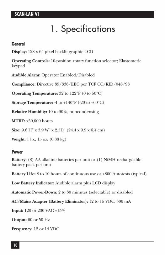
1. Specifications
General
Display: 128 x 64 pixel backlit graphic LCD
Operating Controls: 10-position rotary function selector; Elastomerickeypad
Audible Alarm: Operator Enabled/Disabled
Compliance: Directive 89/336/EEC per TCF CC/KID/048/98
Operating Temperature: 32 to 122°F (0 to 50°C)
Storage Temperature: -4 to +140°F (-20 to +60°C)
Relative Humidity: 10 to 90%, noncondensing
MTBF: >50,000 hours
Size: 9.6 H" x 3.9 W" x 2.5D" (24.4 x 9.9 x 6.4 cm)
Weight: 1 lb., 15 oz. (0.88 kg)
Power
Battery: (8) AA alkaline batteries per unit or (1) NiMH rechargeablebattery pack per unit
Battery Life: 8 to 10 hours of continuous use or >800 Autotests (typical)
Low Battery Indicator: Audible alarm plus LCD display
Automatic Power-Down: 2 to 30 minutes (selectable) or disabled
AC/Mains Adapter (Battery Eliminator): 12 to 15 VDC, 300 mA
Input: 120 or 230 VAC ±15%
Output: 60 or 50 Hz
Frequency: 12 or 14 VDC
11
CHAPTER 1: Specifications
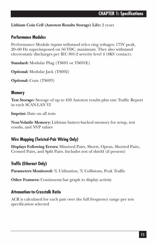
Lithium Coin Cell (Autotest Results Storage) Life: 2 years
Performance Modules
Performance Module inputs withstand telco ring voltages; 175V peak,20–60 Hz superimposed on 56 VDC, maximum. They also withstandelectrostatic discharges per IEC 801-2 severity level 4 (8KV contact).
Standard: Modular Plug (TS691 or TS691E)
Optional: Modular Jack (TS692)
Optional: Coax (TS693)
Memory
Test Storage: Storage of up to 450 Autotest results plus one Traffic Reportin each SCAN-LAN VI
Imprint: Date on all tests
Non-Volatile Memory: Lithium battery-backed memory for setup, testresults, and NVP values
Wire Mapping (Twisted-Pair Wiring Only)
Displays Following Errors: Miswired Pairs, Shorts, Opens, Shorted Pairs,Crossed Pairs, and Split Pairs. Includes test of shield (if present)
Traffic (Ethernet Only)
Parameters Monitored: % Utilization, % Collisions, Peak Traffic
Other Features: Continuous bar graph to display activity
Attenuation-to-Crosstalk Ratio
ACR is calculated for each pair over the full frequency range per testspecification selected
12
SCAN-LAN VI
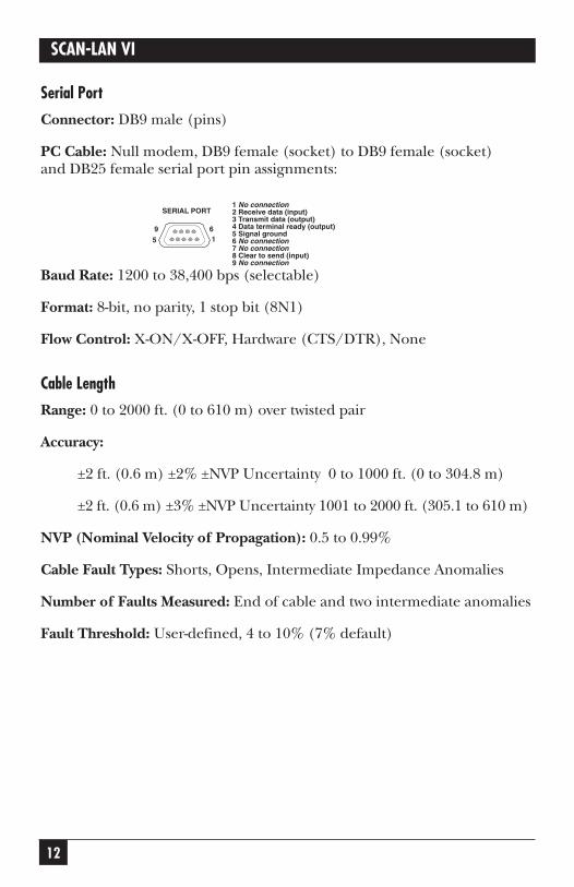
Serial Port
Connector: DB9 male (pins)
PC Cable: Null modem, DB9 female (socket) to DB9 female (socket) and DB25 female serial port pin assignments:
Baud Rate: 1200 to 38,400 bps (selectable)
Format: 8-bit, no parity, 1 stop bit (8N1)
Flow Control: X-ON/X-OFF, Hardware (CTS/DTR), None
Cable Length
Range: 0 to 2000 ft. (0 to 610 m) over twisted pair
Accuracy:
±2 ft. (0.6 m) ±2% ±NVP Uncertainty 0 to 1000 ft. (0 to 304.8 m)
±2 ft. (0.6 m) ±3% ±NVP Uncertainty 1001 to 2000 ft. (305.1 to 610 m)
NVP (Nominal Velocity of Propagation): 0.5 to 0.99%
Cable Fault Types: Shorts, Opens, Intermediate Impedance Anomalies
Number of Faults Measured: End of cable and two intermediate anomalies
Fault Threshold: User-defined, 4 to 10% (7% default)
1 No connection2 Receive data (input)3 Transmit data (output)4 Data terminal ready (output)5 Signal ground6 No connection7 No connection8 Clear to send (input)9 No connection
SERIAL PORT
69
5 1
13
CHAPTER 1: Specifications
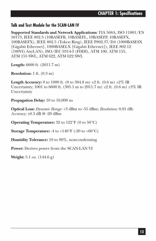
Talk and Test Module for the SCAN-LAN IV
Supported Standards and Network Applications: TIA 568A, ISO 11801/EN50173, IEEE 802.3 (10BASEFB, 10BASEFL, 10BASEFP, 10BASEFX,100BASEFX), IEEE 802.5 (Token Ring), IEEE P802.37/D4 (1000BASESX[Gigabit Ethernet], 1000BASELX [Gigabit Ethernet]), IEEE 802.12(100VG AnyLAN), ISO/IEC 9314-3 (FDDI), ATM 100, ATM 155, ATM 155 SWL, ATM 622, ATM 622 SWL
Length: 6600 ft. (2011.7 m)
Resolution: 1 ft. (0.3 m)
Length Accuracy: 0 to 1000 ft. (0 to 304.8 m) ±2 ft. (0.6 m) ±2% IRUncertainty; 1001 to 6600 ft. (305.1 m to 2011.7 m) ±2 ft. (0.6 m) ±3% IRUncertainty
Propagation Delay: 10 to 10,000 ns
Optical Loss: Dynamic Range: +3 dBm to -55 dBm; Resolution: 0.01 dB;Accuracy: ±0.3 dB @ -20 dBm
Operating Temperature: 32 to 122°F (0 to 50°C)
Storage Temperature: -4 to +140°F (-20 to +60°C)
Humidity Tolerance: 10 to 90%, noncondensing
Power: Derives power from the SCAN-LAN VI
Weight: 5.1 oz. (144.6 g)

14
SCAN-LAN VI
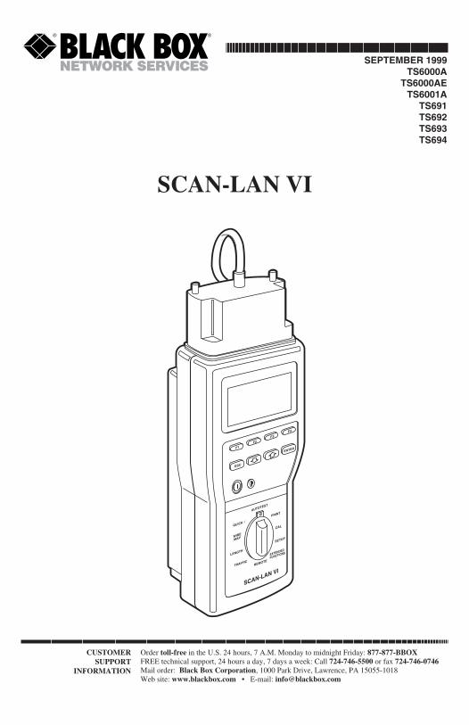
2. IntroductionThe SCAN-LAN VI is a testing system that troubleshoots and certifies LANcable installations. Along with 250 MHz Performance Modules (includedor ordered as part number TS691), the SCAN-LAN VI consists of twohandheld units, one functioning as a main unit, and the other as a remoteunit. It also features LinkTalk voice communications across twisted-pair testlinks. Each unit has a built-in microphone and earphone jack.
The Performance Modules take Category 5 testing beyond currentCategory 5 standards of 100 MHz, providing critical information forenhanced CAT 5 and Gigabit cabling. The SCAN-LAN VI offers anunequaled combination of power and measurement precision—and it’seasy to use and inexpensive. The unique modular design makes SCAN-LAN VI the most versatile tester on the market.
In addition to being fully compliant with TIA TSB 67 requirements for certifyingCAT 5/Class D links, the SCAN-LAN VI performs several important new measure-ments including Power Sum Near End Crosstalk (PS-NEXT) and Power SumAttenuation-to-Crosstalk Ratio (PS-ACR) to 250 MHz.
Padded protective overcases supplied with the system enclose both the testerand performance module, protecting them from damage in the field whileallowing full access to the display and all controls.
The Talk and Test Module for the SCAN-LAN IV certifies multimode fiber inpairs by comparing bi-directional dual-wavelength 850/1300 nm loss, length, andpropagation delay measurement against several industry standards.
15
CHAPTER 2: Introduction
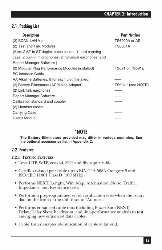
2.1 Packing List
Description Part Number(2) SCAN-LAN VIs TS6000A or AE
(2) Test and Talk Modules TS6001A
(Also, 2 ST to ST duplex patch cables, 1 hard carrying
case, 2 built-in microphones, 2 individual earphones, and
Report Manager Software.)
(2) Modular Plug Performance Modules (installed) TS691 or TS691E
PC Interface Cable –––
AA Alkaline Batteries, 8 for each unit (installed) –––
(2) Battery Eliminators (AC/Mains Adapter) TS694 * (see NOTE)
(2) LinkTalk earphones ——
Report Manager Software ——
Calibration standard and coupler ——
(2) Handset cases ——
Carrying Case ——
User’s Manual –––
*NOTEThe Battery Eliminators provided may differ in various countries. Seethe optional accessories list in Appendix C.
2.2 Features
2.2.1 TESTING FEATURES
• Tests UTP, ScTP, coaxial, STP, and fiberoptic cable.
• Certifies twisted-pair cable up to EIA/TIA 568A Category 5 andISO/IEC 11801 Class D (100 MHz).
• Performs NEXT, Length, Wire Map, Attenuation, Noise, Traffic,Impedance, and Resistance tests.
• Performs a preprogrammed set of certification tests when the rotarydial on the front of the unit is set to “Autotest.”
• Performs enhanced cable tests including Power Sum NEXT,Delay/Delay Skew, headroom, and link-performance analysis to testemerging new enhanced data cables.
• Cable Toner enables identification of cable at far end.
16
SCAN-LAN VI
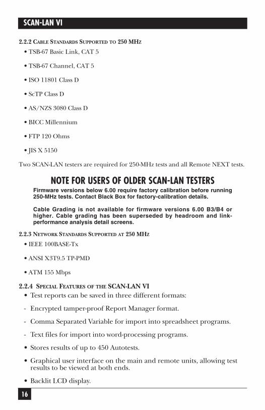
2.2.2 CABLE STANDARDS SUPPORTED TO 250 MHZ
• TSB-67 Basic Link, CAT 5
• TSB-67 Channel, CAT 5
• ISO 11801 Class D
• ScTP Class D
• AS/NZS 3080 Class D
• BICC Millennium
• FTP 120 Ohms
• JIS X 5150
Two SCAN-LAN testers are required for 250-MHz tests and all Remote NEXT tests.
NOTE FOR USERS OF OLDER SCAN-LAN TESTERSFirmware versions below 6.00 require factory calibration before running250-MHz tests. Contact Black Box for factory-calibration details.
Cable Grading is not available for firmware versions 6.00 B3/B4 orhigher. Cable grading has been superseded by headroom and link-performance analysis detail screens.
2.2.3 NETWORK STANDARDS SUPPORTED AT 250 MHZ
• IEEE 100BASE-Tx
• ANSI X3T9.5 TP-PMD
• ATM 155 Mbps
2.2.4 SPECIAL FEATURES OF THE SCAN-LAN VI• Test reports can be saved in three different formats:
- Encrypted tamper-proof Report Manager format.
- Comma Separated Variable for import into spreadsheet programs.
- Text files for import into word-processing programs.
• Stores results of up to 450 Autotests.
• Graphical user interface on the main and remote units, allowing testresults to be viewed at both ends.
• Backlit LCD display.
17
CHAPTER 2: Introduction
• Easy field updates of hardware and software using plug-in PerformanceModules and flash memory.
• Operates using either replaceable AA batteries, AC/mains power, or a rechargeable NiMH battery pack.
• Voice communication between main unit and the remote.
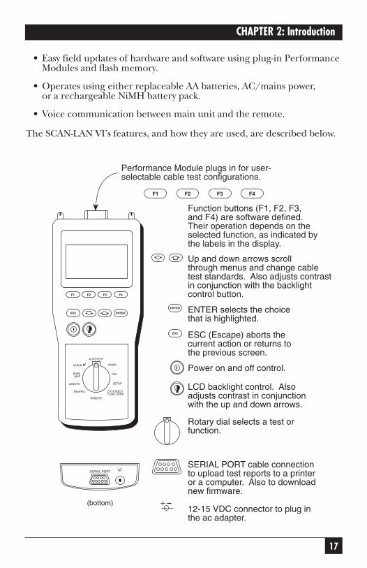
The SCAN-LAN VI’s features, and how they are used, are described below.
12-15 VDC connector to plug inthe ac adapter.
(bottom)
SERIAL PORT cable connectionto upload test reports to a printeror a computer. Also to downloadnew firmware.
Rotary dial selects a test orfunction.
LCD backlight control. Alsoadjusts contrast in conjunctionwith the up and down arrows.
Power on and off control.
ESC (Escape) aborts thecurrent action or returns tothe previous screen.
ENTER selects the choicethat is highlighted.
Up and down arrows scrollthrough menus and change cabletest standards. Also adjusts contrastin conjunction with the backlightcontrol button.
Function buttons (F1, F2, F3,and F4) are software defined.Their operation depends on theselected function, as indicated bythe labels in the display.
Performance Module plugs in for user-selectable cable test configurations.
ESC
ENTER
F1 F2 F3 F4
SERIAL PORT+
100 MHz
EXTENDEDFUNCTIONS
QUICK
AUTOTEST
WIREMAP
REMOTE
TRAFFIC
CAL
SETUPLENGTH
ESC ENTER
F1 F2 F3 F4
18
SCAN-LAN VI
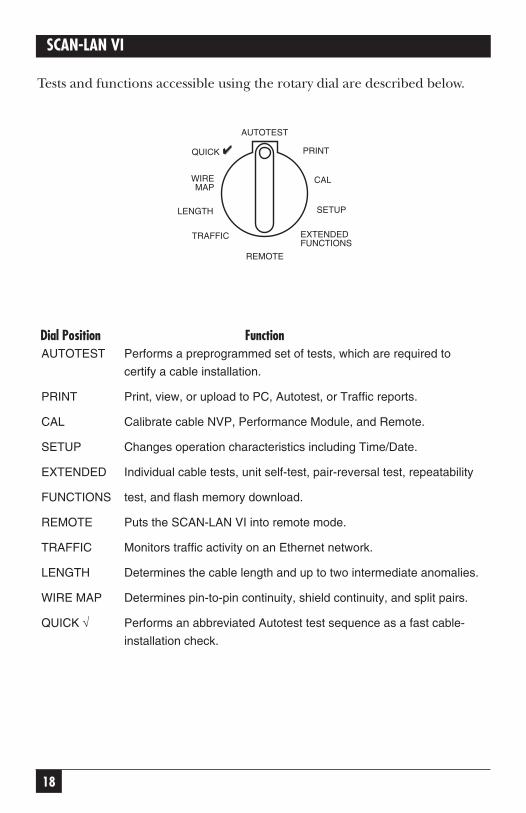
Tests and functions accessible using the rotary dial are described below.
Dial Position FunctionAUTOTEST Performs a preprogrammed set of tests, which are required to
certify a cable installation.
PRINT Print, view, or upload to PC, Autotest, or Traffic reports.
CAL Calibrate cable NVP, Performance Module, and Remote.
SETUP Changes operation characteristics including Time/Date.
EXTENDED Individual cable tests, unit self-test, pair-reversal test, repeatability
FUNCTIONS test, and flash memory download.
REMOTE Puts the SCAN-LAN VI into remote mode.
TRAFFIC Monitors traffic activity on an Ethernet network.
LENGTH Determines the cable length and up to two intermediate anomalies.
WIRE MAP Determines pin-to-pin continuity, shield continuity, and split pairs.
QUICK √ Performs an abbreviated Autotest test sequence as a fast cable-
installation check.
EXTENDEDFUNCTIONS
QUICK
AUTOTEST
WIREMAP
REMOTE
TRAFFIC
CAL
SETUPLENGTH
19
CHAPTER 2: Introduction
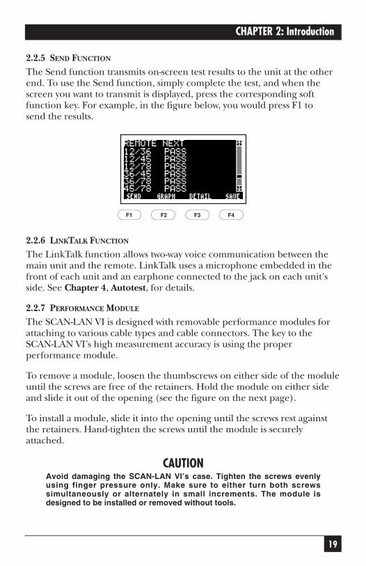
2.2.5 SEND FUNCTION
The Send function transmits on-screen test results to the unit at the otherend. To use the Send function, simply complete the test, and when thescreen you want to transmit is displayed, press the corresponding softfunction key. For example, in the figure below, you would press F1 to send the results.
2.2.6 LINKTALK FUNCTION
The LinkTalk function allows two-way voice communication between themain unit and the remote. LinkTalk uses a microphone embedded in thefront of each unit and an earphone connected to the jack on each unit’sside. See Chapter 4, Autotest, for details.
2.2.7 PERFORMANCE MODULE
The SCAN-LAN VI is designed with removable performance modules forattaching to various cable types and cable connectors. The key to theSCAN-LAN VI’s high measurement accuracy is using the properperformance module.
To remove a module, loosen the thumbscrews on either side of the moduleuntil the screws are free of the retainers. Hold the module on either sideand slide it out of the opening (see the figure on the next page).
To install a module, slide it into the opening until the screws rest againstthe retainers. Hand-tighten the screws until the module is securelyattached.
CAUTIONAvoid damaging the SCAN-LAN VI’s case. Tighten the screws evenlyusing finger pressure only. Make sure to either turn both screwssimultaneously or alternately in small increments. The module isdesigned to be installed or removed without tools.
F1 F2 F3 F4

20
SCAN-LAN VI
Removing or installing the performance module.
BEWARE OF STATIC ELECTRICITY!The SCAN-LAN VI contains static-sensitive electronics inside the mainbody. Use appropriate precautions when removing and installingperformance modules.
2.3 Battery Information
The SCAN-LAN VI handheld is shipped with 8 AA alkaline batteries perunit.
Two rechargeable nickel metal hydride (NiMH) battery eliminators arealso included.
A low battery message appears on the LCD screen when it is time toreplace the batteries. When this message appears, you have 60 seconds to save your test results before the unit automatically powers down.
2.3.1 MEMORY STORAGE
The SCAN-LAN VI’s memory is powered from an internal, long-life lithiumcell. Stored test results and setup conditions will therefore be saved whenyou replace the AA alkaline batteries or rechargeable battery eliminator.
2.3.2 CHARGING MODE
When the AC/Mains adapter is used and the SCAN-LAN VI is powered“off,” the unit goes into a “sleep mode.” With the NiMH re-chargeablebattery eliminator installed, the unit goes into a Recharge mode. A fullydischarged battery eliminator will take approximately 10 to 12 hours tocharge to full capacity. To resume testing, press the Power button.
EXTE
NDED
FUNC
TIO
NS
LENG
TH
PRIN
T
QUI
CKAU
TOTE
STW
IRE
MAP
SETU
PCALF1
F2
F3
F4
100M
Hz
NOIS
E
TRAF
FIC
ENTE
R
ESC
√
21
CHAPTER 2: Introduction
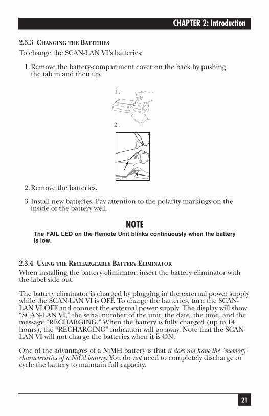
2.3.3 CHANGING THE BATTERIES
To change the SCAN-LAN VI’s batteries:
1.Remove the battery-compartment cover on the back by pushing the tab in and then up.
2.Remove the batteries.
3. Install new batteries. Pay attention to the polarity markings on theinside of the battery well.
NOTEThe FAIL LED on the Remote Unit blinks continuously when the batteryis low.
2.3.4 USING THE RECHARGEABLE BATTERY ELIMINATOR
When installing the battery eliminator, insert the battery eliminator withthe label side out.
The battery eliminator is charged by plugging in the external power supplywhile the SCAN-LAN VI is OFF. To charge the batteries, turn the SCAN-LAN VI OFF and connect the external power supply. The display will show“SCAN-LAN VI,” the serial number of the unit, the date, the time, and themessage “RECHARGING.” When the battery is fully charged (up to 14hours), the “RECHARGING” indication will go away. Note that the SCAN-LAN VI will not charge the batteries when it is ON.
One of the advantages of a NiMH battery is that it does not have the “memory”characteristics of a NiCd battery. You do not need to completely discharge orcycle the battery to maintain full capacity.
2 .
1 .
22
SCAN-LAN VI
Like NiCd batteries, the NiMH batteries do self-discharge over time. Afterstorage for several weeks, they may have only a fraction of their initialcharge. The rate of self-discharge is dependent on temperature: Self-discharge is slower at lower temperatures. We recommend charging the battery pack the night before any planned use.
Note that the “RECHARGING” message should ALWAYS appear for at least a short period at the beginning of the charging process. If the batterypack is completely charged, the message will then go away. If the unit is turned OFF while using the external power supply and the message“RECHARGING” does not immediately appear, the charging function is not working properly. Contact Black Box.
If you have any problems recharging the battery pack, or you have anyother problems or questions, call Black Box.
2.4 Display Conventions
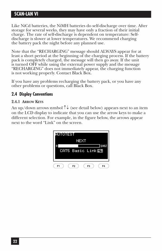
2.4.1 ARROW KEYS
An up/down arrows symbol ↑↓ (see detail below) appears next to an itemon the LCD display to indicate that you can use the arrow keys to make adifferent selection. For example, in the figure below, the arrows appearnext to the word “Link” on the screen.
F1 F2 F3 F4
23
CHAPTER 2: Introduction
To change a selection,
1. Press the up or down arrow key to scroll through the availableselections.
2. When the choice you want is highlighted, press SAVE (F4) or ENTER.
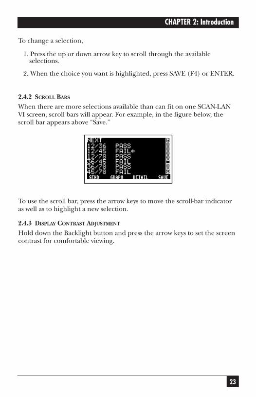
2.4.2 SCROLL BARS
When there are more selections available than can fit on one SCAN-LANVI screen, scroll bars will appear. For example, in the figure below, thescroll bar appears above “Save.”
To use the scroll bar, press the arrow keys to move the scroll-bar indicatoras well as to highlight a new selection.
2.4.3 DISPLAY CONTRAST ADJUSTMENT
Hold down the Backlight button and press the arrow keys to set the screencontrast for comfortable viewing.
24
SCAN-LAN VI
3. Getting StartedThis chapter provides a brief overview of how to use the SCAN-LAN VI fortesting twisted-pair cabling. It is intended for users with prior cable-testingexperience who want to get started quickly. It covers only the basics ofinitial setup, connections to the cable, and the Autotest function. If youhave no prior cable-testing experience, review Chapter 8, Testing Twisted-Pair Cable, before using this instrument.
3.1 Initial Setup
Before you first use the SCAN-LAN VI, you should check SETUP. SETUPcontrols many basic instrument operations such as power-down time,backlight “on” time, feet/meters, date, time, and serial-output format.Each of these settings has a “default” value established by the factory. Toadjust any of these settings, refer to Chapter 9, Setup.
3.1.1 SETTING UP THE SCAN-LAN VITo set up the SCAN-LAN VI:
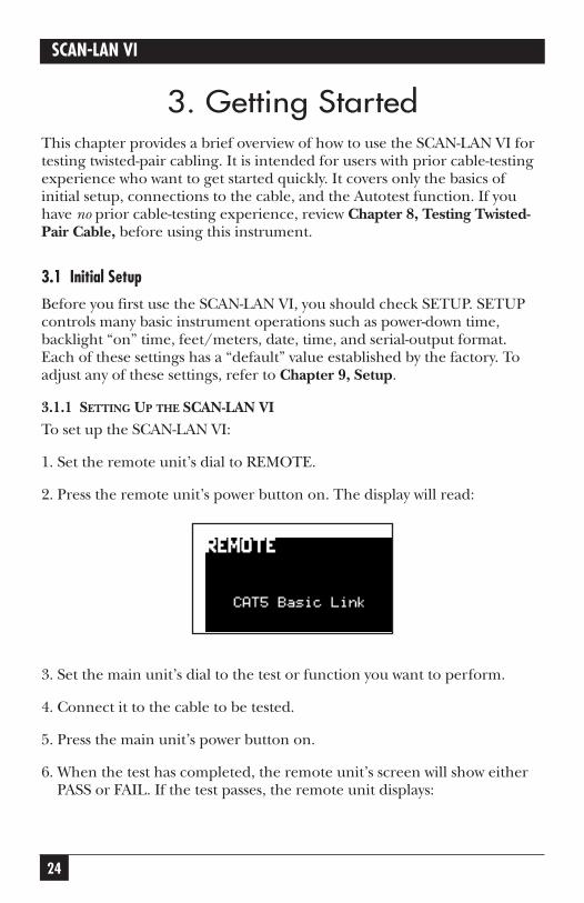
1. Set the remote unit’s dial to REMOTE.
2. Press the remote unit’s power button on. The display will read:
3. Set the main unit’s dial to the test or function you want to perform.
4. Connect it to the cable to be tested.
5. Press the main unit’s power button on.
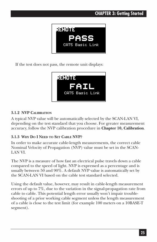
6. When the test has completed, the remote unit’s screen will show either PASS or FAIL. If the test passes, the remote unit displays:
25
CHAPTER 3: Getting Started
If the test does not pass, the remote unit displays:
3.1.2 NVP CALIBRATION
A typical NVP value will be automatically selected by the SCAN-LAN VI,depending on the test standard that you choose. For greater measurementaccuracy, follow the NVP calibration procedure in Chapter 10, Calibration.
3.1.3 WHY DO I NEED TO SET CABLE NVP?In order to make accurate cable-length measurements, the correct cableNominal Velocity of Propagation (NVP) value must be set in the SCAN-LAN VI.
The NVP is a measure of how fast an electrical pulse travels down a cablecompared to the speed of light. NVP is expressed as a percentage and isusually between 50 and 90%. A default NVP value is automatically set bythe SCAN-LAN VI based on the cable test standard selected.
Using the default value, however, may result in cable-length measurementerrors of up to 7%, due to the variation in the signal-propagation rate fromcable to cable. This potential length error usually won’t impair trouble-shooting of a prior working cable segment unless the length measurementof a cable is close to the test limit (for example 100 meters on a 10BASE-Tsegment).
26
SCAN-LAN VI
When using the SCAN-LAN VI for cable certification, determine the truecable NVP and save the value. This will ensure the most accurate cable-length measurements and will avoid failing cable segments that are close to the test limit.
3.2 Typical Test Setup
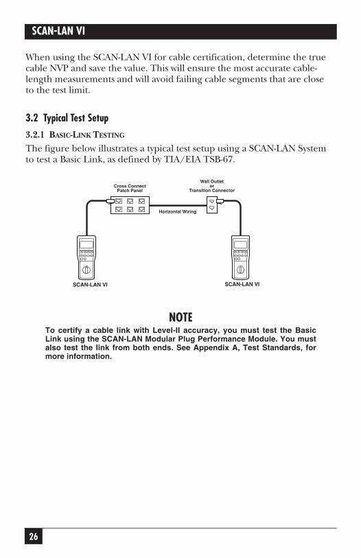
3.2.1 BASIC-LINK TESTING
The figure below illustrates a typical test setup using a SCAN-LAN Systemto test a Basic Link, as defined by TIA/EIA TSB-67.
NOTETo certify a cable link with Level-II accuracy, you must test the BasicLink using the SCAN-LAN Modular Plug Performance Module. You mustalso test the link from both ends. See Appendix A, Test Standards, formore information.
TwoWay Remote
Horizontal Wiring
Cross ConnectPatch Panel
Wall Outletor
Transition Connector
TwoWay Main SCAN-LAN VISCAN-LAN VI
27
CHAPTER 3: Getting Started
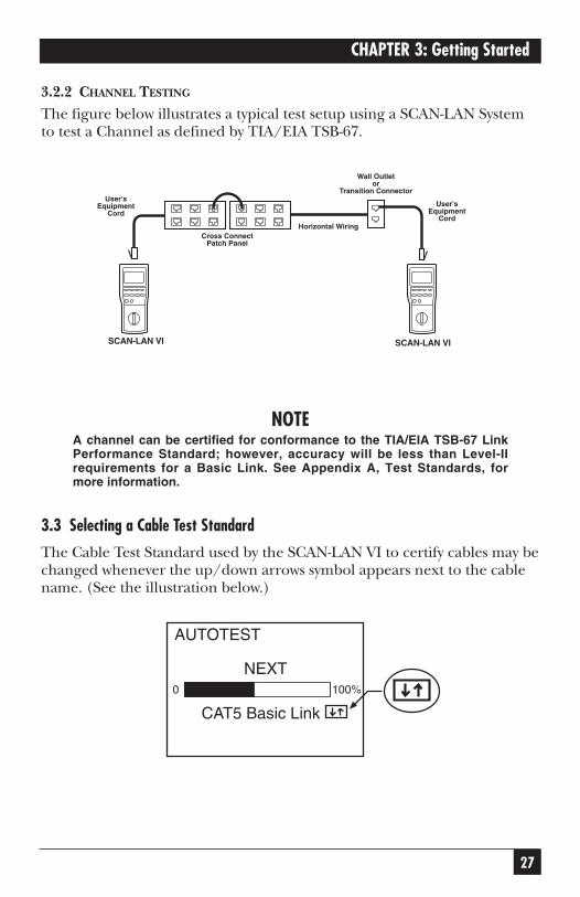
3.2.2 CHANNEL TESTING
The figure below illustrates a typical test setup using a SCAN-LAN Systemto test a Channel as defined by TIA/EIA TSB-67.
NOTEA channel can be certified for conformance to the TIA/EIA TSB-67 LinkPerformance Standard; however, accuracy will be less than Level-IIrequirements for a Basic Link. See Appendix A, Test Standards, formore information.
3.3 Selecting a Cable Test Standard
The Cable Test Standard used by the SCAN-LAN VI to certify cables may bechanged whenever the up/down arrows symbol appears next to the cablename. (See the illustration below.)
AUTOTEST
CAT5 Basic Link
NEXT100%0
TwoWay Remote
Horizontal WiringCross Connect
Patch Panel
Wall Outletor
Transition Connector
TwoWay Main
User'sEquipment
CordUser's
EquipmentCord
SCAN-LAN VI SCAN-LAN VI
28
SCAN-LAN VI
To select a different cable test standard:
1.Set the dial to Autotest, Quick √, Wire Map, Length, or Traffic.
2.Press either arrow key to display the cable-standard library and select a different cable test standard.
3.When the desired cable test standard is highlighted, press SELECT(F4) or Enter. The SCAN-LAN VI immediately begins testing using the new cable test standard.
NOTERefer to Appendix A, Test Standards, for assistance in choosing anappropriate cable test standard. This chapter explains when to select acable standard and when to select a network standard.
When using a SCAN-LAN VI System, cable standards are compared atboth ends. If they differ, the standard on the remote end will be changedto match that of the main end.
3.4 Defining Custom Standards
Existing cable test standards can be modified to create a maximum of 23 additional custom standards. Custom standards are initially labeled as Custom #1 and Custom #2. Once you have defined a new standard, it appears in the cable-standard library identified by an asterisk (*).
The tests performed and the PASS/FAIL limits are set by copying one ofthe existing cable test standards. The customization consists of selectingwhich pairs will be included in the test and whether or not the shield isrequired to be present for the Wire Map to PASS.
To create a custom standard:
1.Set dial to Autotest, Quick √, Wire Map, Length, or Traffic.
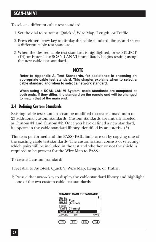
2.Press either arrow key to display the cable-standard library and highlightone of the two custom cable test standards.
CHANGE CABLE STANDARD
CANCEL*CAT5 Channel
EDIT SAVE
RG-59RG-59 FoamRG-62 (Arcnet)FIBER*CAT5 Channel
F1 F2 F3 F4
29
CHAPTER 3: Getting Started
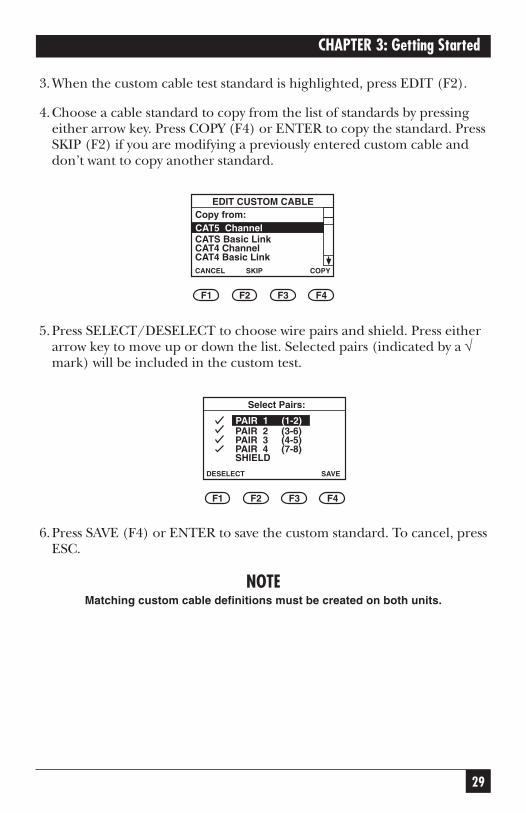
3.When the custom cable test standard is highlighted, press EDIT (F2).
4.Choose a cable standard to copy from the list of standards by pressingeither arrow key. Press COPY (F4) or ENTER to copy the standard. PressSKIP (F2) if you are modifying a previously entered custom cable anddon’t want to copy another standard.
5.Press SELECT/DESELECT to choose wire pairs and shield. Press eitherarrow key to move up or down the list. Selected pairs (indicated by a √mark) will be included in the custom test.
6.Press SAVE (F4) or ENTER to save the custom standard. To cancel, pressESC.
NOTEMatching custom cable definitions must be created on both units.
Select Pairs:
DESELECT
PAIR 1 (1-2)
SAVE
PAIR 2 (3-6)PAIR 3 (4-5)PAIR 4 (7-8)
F1 F2 F3 F4
SHIELD
EDIT CUSTOM CABLE
CANCEL
CAT5 Channel
SKIP COPY
Copy from:
CATS Basic LinkCAT4 ChannelCAT4 Basic Link
F1 F2 F3 F4
30
SCAN-LAN VI
3.5 System Integrity Pre-Test
Before testing an installation, the integrity of the SCAN-LAN VI system may be checked by running these tests.
To pre-test your system:
1. Connect the main and remote units using a CAT3 coupler or a patch cable.
2. Run Self-Test.
3. Run Pair Reversal.
4. Run Repeatability.
5. Run Autotest.
6. If FAIL occurs on any test result, call Technical Support at 724-746-5500.
31
CHAPTER 4: Autotest
4. AutotestAutotest is a preprogrammed set of tests which are required to certify a cable installation. All of the tests performed by Autotest can also beperformed individually.
Autotest performs these tests: Wire Map, Near-End Crosstalk (NEXT) at both ends for Two-Way testing, Attenuation, ACR, and Length. Thefollowing tests may be added to the Autotest suite of tests by defining acustom cable standard: Impedance, Delay/Delay Skew, 250 MHz UTP,Power Sum Link Performance, Power Sum NEXT, Power Sum ACR, Cable Grading, and Resistance.
NOTES ON 250-MHz TESTING• 250-MHz testing is available for all 100-MHz tests. This option isavailable by entering the CHANGE CABLE STANDARD menu and editingthe selected test standard. Using this option, the instrument will extendNEXT and ATTENUATION measurements out to 250 MHz.
• PASS or FAIL indications when running Autotest are based on existing100-MHz test standards.
• 250-MHz tests can also be enabled by selecting “250 MHz UTP” in theCable Standard menu.
• If the SCAN-LAN fails any test, it will stop and display the failure. Youmay continue testing by pressing the CONTINUE (F4) softkey.
Refer to Chapter 6, Cable Test Descriptions, for a complete description of these and other tests performed by the SCAN-LAN VI.
Refer to Chapter 7, Printing, Uploading, and Viewing Test Results, formore information about printing test results and uploading test results to a PC.
4.1 Running Autotest1. Connect one end of cable to the main unit and the other end to the
remote unit.
2. Set the remote unit’s dial to REMOTE.
Set the main unit’s dial to AUTOTEST. The test runs automatically,then displays the results. (Press the arrow keys to change the cable test standard.)

32
SCAN-LAN VI
3. Press Start (F1) to re-start Autotest. Press VIEW (F3) to review Autotesttest results.
4. Press SAVE (F4) or ENTER to save the Autotest test results.
5. Press TALK (F2) to ring the Remote Unit at the other end.
NOTEIf the SCAN-LAN VI fails any test, it will stop and display the failure. Youmay continue testing by pressing the CONTINUE (F4) softkey.
4.2 Viewing Autotest Results
Autotest results are displayed in either summary or detailed mode.
This section describes a general procedure for reviewing Autotest resultsincluding summary screens for Wire Map, NEXT, Attenuation, ACR,Length, and Propagation Delay tests, and detailed test results for NEXTand Attenuation. Refer to Chapter 6, Cable Test Descriptions, for moreinformation on interpreting test-result screens.
AUTOTEST
START SAVE
PASS
F1 F2 F3 F4
TALK VIEW
CAT3 Channel1
F1 F2 F3 F4
33
CHAPTER 4: Autotest
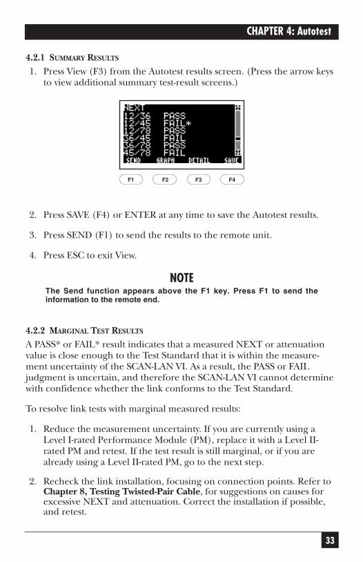
4.2.1 SUMMARY RESULTS
1. Press View (F3) from the Autotest results screen. (Press the arrow keysto view additional summary test-result screens.)
2. Press SAVE (F4) or ENTER at any time to save the Autotest results.
3. Press SEND (F1) to send the results to the remote unit.
4. Press ESC to exit View.
NOTEThe Send function appears above the F1 key. Press F1 to send theinformation to the remote end.
4.2.2 MARGINAL TEST RESULTS
A PASS* or FAIL* result indicates that a measured NEXT or attenuationvalue is close enough to the Test Standard that it is within the measure-ment uncertainty of the SCAN-LAN VI. As a result, the PASS or FAILjudgment is uncertain, and therefore the SCAN-LAN VI cannot determinewith confidence whether the link conforms to the Test Standard.
To resolve link tests with marginal measured results:
1. Reduce the measurement uncertainty. If you are currently using aLevel I-rated Performance Module (PM), replace it with a Level II-rated PM and retest. If the test result is still marginal, or if you arealready using a Level II-rated PM, go to the next step.
2. Recheck the link installation, focusing on connection points. Refer toChapter 8, Testing Twisted-Pair Cable, for suggestions on causes forexcessive NEXT and attenuation. Correct the installation if possible,and retest.
F1 F2 F3 F4
34
SCAN-LAN VI
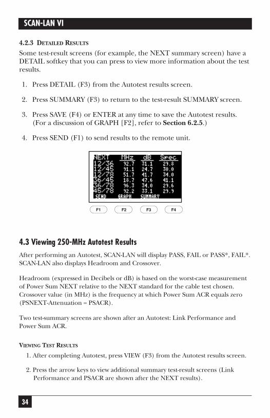
4.2.3 DETAILED RESULTS
Some test-result screens (for example, the NEXT summary screen) have aDETAIL softkey that you can press to view more information about the testresults.
1. Press DETAIL (F3) from the Autotest results screen.
2. Press SUMMARY (F3) to return to the test-result SUMMARY screen.
3. Press SAVE (F4) or ENTER at any time to save the Autotest results.(For a discussion of GRAPH [F2], refer to Section 6.2.5.)
4. Press SEND (F1) to send results to the remote unit.
4.3 Viewing 250-MHz Autotest ResultsAfter performing an Autotest, SCAN-LAN will display PASS, FAIL or PASS*, FAIL*.SCAN-LAN also displays Headroom and Crossover.
Headroom (expressed in Decibels or dB) is based on the worst-case measurementof Power Sum NEXT relative to the NEXT standard for the cable test chosen.Crossover value (in MHz) is the frequency at which Power Sum ACR equals zero(PSNEXT-Attenuation = PSACR).
Two test-summary screens are shown after an Autotest: Link Performance andPower Sum ACR.
VIEWING TEST RESULTS
1. After completing Autotest, press VIEW (F3) from the Autotest results screen.
2. Press the arrow keys to view additional summary test-result screens (LinkPerformance and PSACR are shown after the NEXT results).
F1 F2 F3 F4
35
CHAPTER 4: Autotest
3. Press SAVE (F4) or ENTER at any time to save the Autotest results.
4. Press GRAPH (F2) to view a graphic display of the test results.
5. Press SEND (Fl) to send the results to the Remote Unit.
6. Press ESC to exit View.
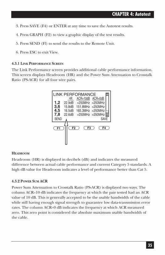
4.3.1 LINK PERFORMANCE SCREEN
The Link Performance screen provides additional cable performance information.This screen displays Headroom (HR) and the Power Sum Attenuation to CrosstalkRatio (PS-ACR) for all four wire pairs.
HEADROOM
Headroom (HR) is displayed in decibels (dB) and indicates the measureddifference between actual cable performance and current Category 5 standards. Ahigh dB value for Headroom indicates a level of performance better than Cat 5.
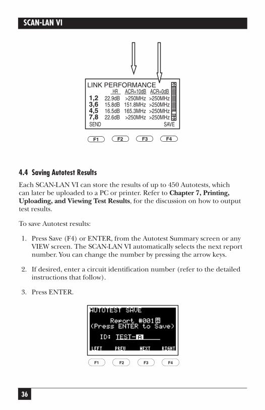
4.3.2 POWER SUM ACR
Power Sum Attenuation to Crosstalk Ratio (PS-ACR) is displayed two ways. Thecolumn ACR=10 dB indicates the frequency at which the pair tested had an ACRvalue of 10 dB. This is generally accepted to be the usable bandwidth of the cablewhile still having enough signal strength to guarantee low data-transmission errorrates. The column ACR=0 dB indicates the frequency at which ACR measuredzero. This zero point is considered the absolute maximum usable bandwidth of the cable.
F1 F2 F3 F4
LINK PERFORMANCE
1,23,64,57,8
22.9dB15.8dB16.5dB22.6dB
>250MHz151.8MHz165.3MHz>250MHz
HR ACR=10dB ACR=0dB
SAVESEND
>250MHz>250MHz>250MHz>250MHz
36
SCAN-LAN VI
4.4 Saving Autotest Results
Each SCAN-LAN VI can store the results of up to 450 Autotests, which can later be uploaded to a PC or printer. Refer to Chapter 7, Printing,Uploading, and Viewing Test Results, for the discussion on how to outputtest results.
To save Autotest results:
1. Press Save (F4) or ENTER, from the Autotest Summary screen or anyVIEW screen. The SCAN-LAN VI automatically selects the next reportnumber. You can change the number by pressing the arrow keys.
2. If desired, enter a circuit identification number (refer to the detailedinstructions that follow).
3. Press ENTER.
F1 F2 F3 F4
F1 F2 F3 F4
LINK PERFORMANCE
1,23,64,57,8
22.9dB15.8dB16.5dB22.6dB
>250MHz151.8MHz165.3MHz>250MHz
HR ACR=10dB ACR=0dB
SAVESEND
>250MHz>250MHz>250MHz>250MHz
37
CHAPTER 4: Autotest
NOTEEither unit may save up to 450 Autotests, giving the SCAN-LAN VISystem the capability of saving 900 Autotests. After you have saved 450Autotests in the main unit, you can switch units, use the remote as themain unit, and save 450 more Autotests.
CAUTIONIf you choose a report number that is in use, the message “In use” isdisplayed.
The SCAN-LAN VI has no overwrite protection. Nothing prevents youfrom saving a report to the same number as a previous report numberand erasing the earlier one.
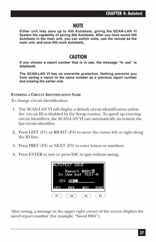
ENTERING A CIRCUIT IDENTIFICATION NAME
To change circuit identification:
1. The SCAN-LAN VI will display a default circuit identification unlessthe circuit ID is disabled by the Setup routine. To speed up enteringcircuit identifiers, the SCAN-LAN VI can automatically increment thelast circuit identifier.
2. Press LEFT (F1) or RIGHT (F4) to move the cursor left or right alongthe ID line.
3. Press PREV (F2) or NEXT (F3) to enter letters or numbers.
4. Press ENTER to save or press ESC to quit without saving.
After saving, a message in the upper right corner of the screen displays thesaved report number (for example, “Saved #001”).
F1 F2 F3 F4
38
SCAN-LAN VI
Autotest report details remain available for viewing until the next test is started.
NOTEAutotest results will be lost if not saved before the SCAN-LAN VI powersdown.
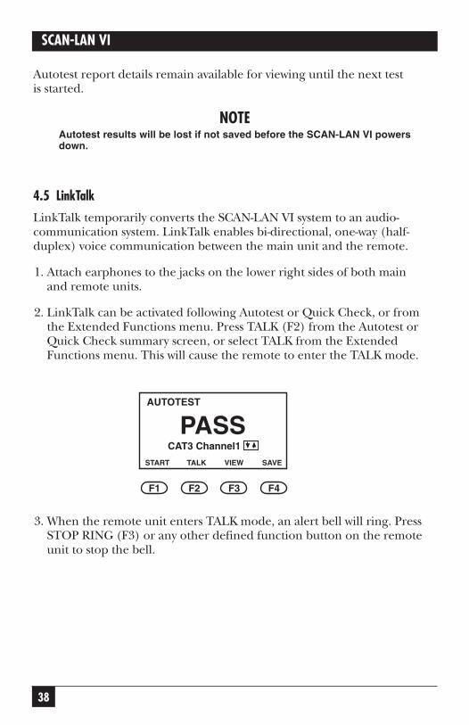
4.5 LinkTalk
LinkTalk temporarily converts the SCAN-LAN VI system to an audio-communication system. LinkTalk enables bi-directional, one-way (half-duplex) voice communication between the main unit and the remote.
1. Attach earphones to the jacks on the lower right sides of both main and remote units.
2. LinkTalk can be activated following Autotest or Quick Check, or fromthe Extended Functions menu. Press TALK (F2) from the Autotest orQuick Check summary screen, or select TALK from the ExtendedFunctions menu. This will cause the remote to enter the TALK mode.
3. When the remote unit enters TALK mode, an alert bell will ring. PressSTOP RING (F3) or any other defined function button on the remoteunit to stop the bell.
AUTOTEST
START SAVE
PASS
F1 F2 F3 F4
TALK VIEW
CAT3 Channel1
39
CHAPTER 4: Autotest
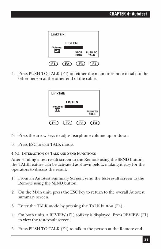
4. Press PUSH TO TALK (F4) on either the main or remote to talk to theother person at the other end of the cable.
5. Press the arrow keys to adjust earphone volume up or down.
6. Press ESC to exit TALK mode.
4.5.1 INTERACTION OF TALK AND SEND FUNCTIONS
After sending a test result screen to the Remote using the SEND button,the TALK feature can be activated as shown below, making it easy for theoperators to discuss the result.
1. From an Autotest Summary Screen, send the test-result screen to theRemote using the SEND button.
2. On the Main unit, press the ESC key to return to the overall Autotestsummary screen.
3. Enter the TALK mode by pressing the TALK button (F4).
4. On both units, a REVIEW (F1) softkey is displayed. Press REVIEW (F1)to view the test-result screen.
5. Press PUSH TO TALK (F4) to talk to the person at the Remote end.
LinkTalk
F1 F2 F3 F4
PUSH TOTALK
LISTENVolume:
LinkTalk
STOPRING
F1 F2 F3 F4
PUSH TOTALK
LISTENVolume:
40
SCAN-LAN VI
6. Press ESC to return to the TALK mode screen.
4.5.2 SYSTEM INTEGRITY PRE-TEST
Before testing an installation, the integrity of the SCAN-LAN VI system maybe checked by running the tests described below.
To pre-test your system:
1. Connect the main and remote units using a CAT3 coupler or a patchcable.
2. Run Self Test.
3. Run Pair Reversal.
4. Run Repeatability.
5. Run Autotest.
6. If FAIL occurs on any test results, call Technical Support for assistance.
41
CHAPTER 5: Quick Check
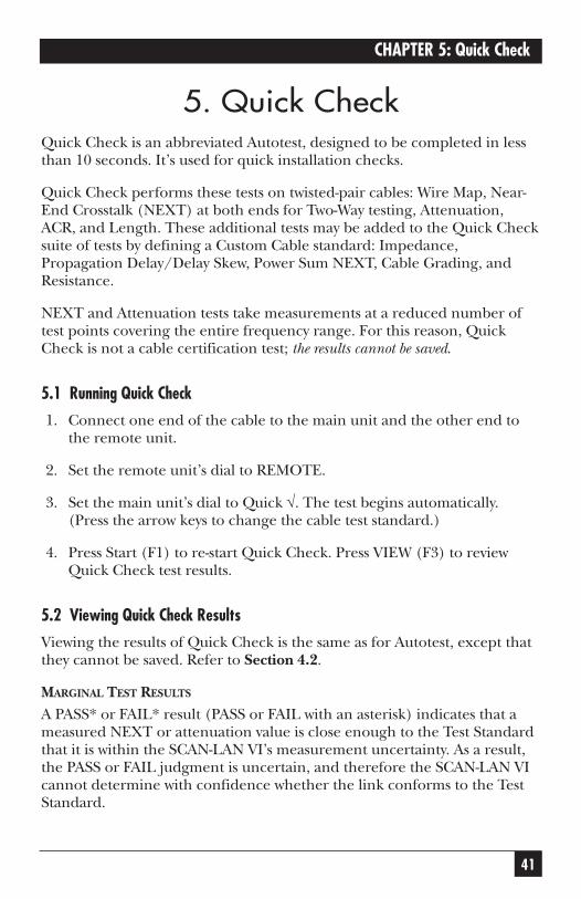
5. Quick CheckQuick Check is an abbreviated Autotest, designed to be completed in lessthan 10 seconds. It’s used for quick installation checks.
Quick Check performs these tests on twisted-pair cables: Wire Map, Near-End Crosstalk (NEXT) at both ends for Two-Way testing, Attenuation,ACR, and Length. These additional tests may be added to the Quick Checksuite of tests by defining a Custom Cable standard: Impedance,Propagation Delay/Delay Skew, Power Sum NEXT, Cable Grading, andResistance.
NEXT and Attenuation tests take measurements at a reduced number oftest points covering the entire frequency range. For this reason, QuickCheck is not a cable certification test; the results cannot be saved.
5.1 Running Quick Check
1. Connect one end of the cable to the main unit and the other end tothe remote unit.
2. Set the remote unit’s dial to REMOTE.
3. Set the main unit’s dial to Quick √. The test begins automatically.(Press the arrow keys to change the cable test standard.)
4. Press Start (F1) to re-start Quick Check. Press VIEW (F3) to reviewQuick Check test results.
5.2 Viewing Quick Check Results
Viewing the results of Quick Check is the same as for Autotest, except thatthey cannot be saved. Refer to Section 4.2.
MARGINAL TEST RESULTS
A PASS* or FAIL* result (PASS or FAIL with an asterisk) indicates that ameasured NEXT or attenuation value is close enough to the Test Standardthat it is within the SCAN-LAN VI’s measurement uncertainty. As a result,the PASS or FAIL judgment is uncertain, and therefore the SCAN-LAN VIcannot determine with confidence whether the link conforms to the TestStandard.
42
SCAN-LAN VI
The following steps may be taken in order to resolve link tests withmarginal measured results:
1. Reduce the measurement uncertainty. If you are currently using aLevel I-rated Performance Module (PM), replace it with a Level II-rated PM and retest. If the test result is still marginal, or if you arealready using a Level II-rated PM, go to the next step.
2. Recheck the link installation, focusing on connection points. Refer toChapter 8, Testing Twisted-Pair Cable, for suggestions on causes forexcessive NEXT and attenuation. Correct the installation, if possible,and retest.

43
CHAPTER 6: Cable Test Descriptions
6. Cable Test DescriptionsThis chapter describes each test, and how to run each test individually. Refer to Chapter 8, Testing Twisted-Pair Cable, for detailed test resultsinterpretation and more troubleshooting tips.
While it is usually recommended to use Autotest for most cable testing,individual cable tests may be useful in troubleshooting specific cableproblems.
For example, Autotest may reveal a wire-map problem requiring remountingof connectors. It may be faster to use the individual Wire-Map test to verify thecorrection and then to perform another Autotest sequence for a certificationrecord.
6.1 Wire MapWire Map checks twisted-pair cable for pin-to-pin and shield continuity, and it also checks for split pairs.
Although it’s one of the tests run during Autotest and Quick Check, it canalso be run individually.
Wire Map tests for reversed pair, shorts, opens, crossed pairs, split pairs,miswires, and shield continuity.
6.1.1 RUNNING WIRE MAP
1. Connect one end of the cable under test to the SCAN-LAN VI and theother end to the remote unit. Set the remote unit’s dial to REMOTE.
2. Set dial to WIRE MAP. The test begins scanning immediately. (Press thearrow keys to select another cable test standard.)
NOTEWire Map runs continuously to enable you to find intermittent wiringproblems.
All four pairs will be tested and the results displayed, even if the selected teststandard does not require all the pairs to be tested. However, a PASS/FAILdetermination is based only on the pairs required by the selected cable-teststandard.
44
SCAN-LAN VI
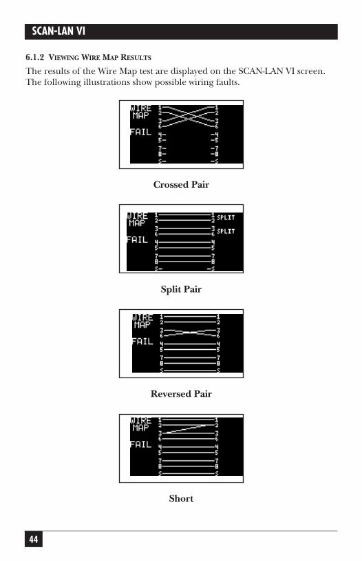
6.1.2 VIEWING WIRE MAP RESULTS
The results of the Wire Map test are displayed on the SCAN-LAN VI screen.The following illustrations show possible wiring faults.
Crossed Pair
Split Pair
Reversed Pair
Short
45
CHAPTER 6: Cable Test Descriptions
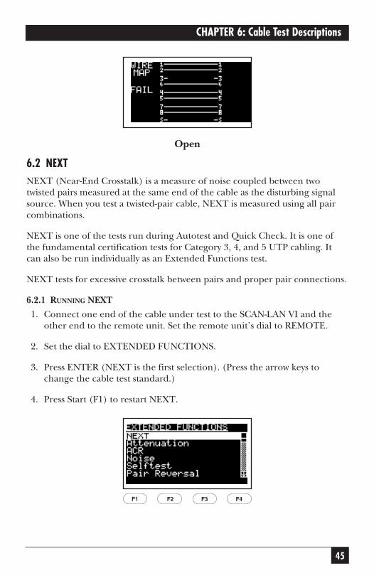
Open
6.2 NEXTNEXT (Near-End Crosstalk) is a measure of noise coupled between twotwisted pairs measured at the same end of the cable as the disturbing signalsource. When you test a twisted-pair cable, NEXT is measured using all paircombinations.
NEXT is one of the tests run during Autotest and Quick Check. It is one ofthe fundamental certification tests for Category 3, 4, and 5 UTP cabling. Itcan also be run individually as an Extended Functions test.
NEXT tests for excessive crosstalk between pairs and proper pair connections.
6.2.1 RUNNING NEXT
1. Connect one end of the cable under test to the SCAN-LAN VI and theother end to the remote unit. Set the remote unit’s dial to REMOTE.
2. Set the dial to EXTENDED FUNCTIONS.
3. Press ENTER (NEXT is the first selection). (Press the arrow keys tochange the cable test standard.)
4. Press Start (F1) to restart NEXT.
F1 F2 F3 F4
46
SCAN-LAN VI
NOTEWhen the NEXT test is performed, both ends are tested.
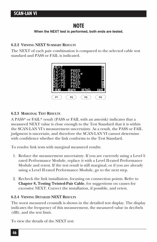
6.2.2 VIEWING NEXT SUMMARY RESULTS
The NEXT of each pair combination is compared to the selected cable teststandard and PASS or FAIL is indicated.
6.2.3 MARGINAL TEST RESULTS
A PASS* or FAIL* result (PASS or FAIL with an asterisk) indicates that ameasured NEXT value is close enough to the Test Standard that it is withinthe SCAN-LAN VI’s measurement uncertainty. As a result, the PASS or FAILjudgment is uncertain, and therefore the SCAN-LAN VI cannot determinewith confidence whether the link conforms to the Test Standard.
To resolve link tests with marginal measured results:
1. Reduce the measurement uncertainty. If you are currently using a Level I-rated Performance Module, replace it with a Level II-rated PerformanceModule and retest. If the test result is still marginal, or if you are alreadyusing a Level II-rated Performance Module, go to the next step.
2. Recheck the link installation, focusing on connection points. Refer toChapter 8, Testing Twisted-Pair Cable, for suggestions on causes forexcessive NEXT. Correct the installation, if possible, and retest.
6.2.4 VIEWING DETAILED NEXT RESULTS
The worst measured crosstalk is shown in the detailed test display. The displayindicates the frequency of this measurement, the measured value in decibels(dB), and the test limit.
To view the details of the NEXT test:
F1 F2 F3 F4
47
CHAPTER 6: Cable Test Descriptions
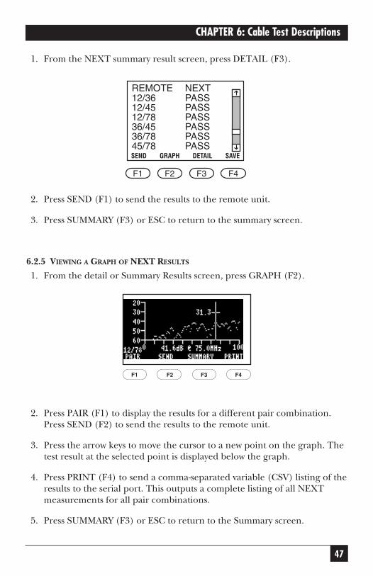
1. From the NEXT summary result screen, press DETAIL (F3).
2. Press SEND (F1) to send the results to the remote unit.
3. Press SUMMARY (F3) or ESC to return to the summary screen.
6.2.5 VIEWING A GRAPH OF NEXT RESULTS
1. From the detail or Summary Results screen, press GRAPH (F2).
2. Press PAIR (F1) to display the results for a different pair combination.Press SEND (F2) to send the results to the remote unit.
3. Press the arrow keys to move the cursor to a new point on the graph. Thetest result at the selected point is displayed below the graph.
4. Press PRINT (F4) to send a comma-separated variable (CSV) listing of theresults to the serial port. This outputs a complete listing of all NEXTmeasurements for all pair combinations.
5. Press SUMMARY (F3) or ESC to return to the Summary screen.
F1 F2 F3 F4
SEND GRAPH DETAIL SAVE
REMOTE NEXT
F1 F2 F3 F4
12/36 PASS12/45 PASS12/78 PASS36/45 PASS36/78 PASS45/78 PASS

48
SCAN-LAN VI
NOTEThe test result displayed on the graph is the worst value found within1-MHz frequency increments for Category 5 and ISO Class D testing. Alltest results are available and can be output from the SCAN-LAN VI.
6.2.6 CERTIFYING CATEGORY 5 CABLING—PAIR-TO-PAIR NEXT METHOD
NEXT, as defined in TIA TSB-67, is a measure of signal coupling from one pair to another pair within the four-pair cable. It is also sometimes called pair-to-pairNEXT. TSB-67 requires that pair-to-pair NEXT be measured on all six paircombinations, and that the worst pair-to-pair NEXT measurement not exceedspecified test limits for the Basic Link or Channel test configurations.
The pair-to-pair NEXT measurements, however, only account for crosstalk coupledfrom any one pair to another—not the possible total crosstalk that might bccoupled from multiple pairs in the same sheath. The TSB-67 methodology assumes that only two pairs of the cable would be used at any given time for datatransmission. While pair-to-pair NEXT is an appropriate crosstalk measure for 2-pair network schemes, such as 10BASE-T and 100-BASE-TX, it does not providean adequate measure of cable performance when multiple pairs within the samesheath may be transmitting simultaneously.
6.3 LengthThe Length test measures the cable length and the distance to a cable fault,such as a short, open, or impedance change.
The Length test locates significant impedance changes or anomalies in a cable segment that may be caused by cable damage or inadequateconnections at patch panels, cross-connect blocks, modular plugs, orwall plates.
Pair-to-Pair NEXTmeasures signalcoupling from onepair to another pair.
49
CHAPTER 6: Cable Test Descriptions
Length is one of the tests run during Autotest and Quick Check. This test canalso be run individually.
The Length test measures length of each pair, locates up to two intermediateimpedance anomalies, and measures propagation delay of each pair.
NOTEThe accuracy of a Length measurement is dependent on the proper cableNVP setting. Refer to Chapter 10, Calibration, for the procedure tocalibrate cable NVP.
6.3.1 RUNNING LENGTH TEST
1. Connect one end of the cable under test to the SCAN-LAN VI.
2. Set dial to LENGTH. The test begins scanning immediately. (Press thearrow keys to select another cable test standard.)
NOTEFor accurate results, do not use the remote unit when performing a Length measurement test, except during Autotest or Quick Check.
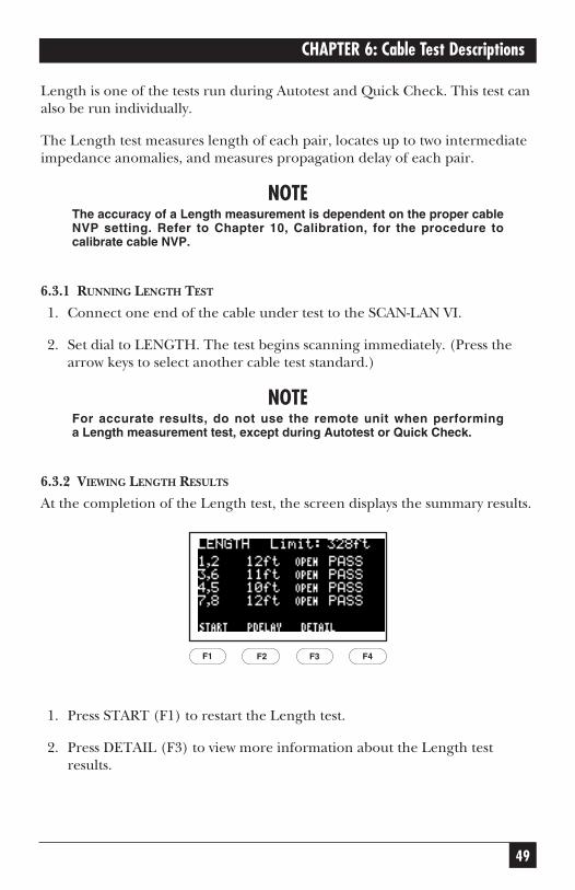
6.3.2 VIEWING LENGTH RESULTS
At the completion of the Length test, the screen displays the summary results.
1. Press START (F1) to restart the Length test.
2. Press DETAIL (F3) to view more information about the Length testresults.
F1 F2 F3 F4
50
SCAN-LAN VI
3. Press PDELAY (F2) to view the Propagation Delay for each pair.
NOTES1. Some variation in the measured length of wire pairs within the samecable is considered normal. This is due to the difference in constructionof the individual pairs.
Length variation from pair to pair will be greater for longer cable lengths.
2. An asterisk (*) next to a PASS result indicates that the measured valueis close enough to the standard input that it is within the SCAN-LAN VI’smeasurement uncertainty.
3. When measuring spooled and other uninstalled cables, the cablelength will probably be greater than the specification test limit. This willcause a FAIL Length test result. In this case, you may ignore the failmessage.
4. A cable found to have a “short” will cause length test to FAILregardless of measured length.
5. OPEN or SHORT usually indicates that a pair ends in an open or ashort. However, if the remote unit is used, an OPEN result should bedisplayed for each pair.
6. Propagation Delay is the time in nanoseconds for a pulse to travel thelength of a twisted pair.
7. For instruction on changing length units (feet/meters), refer toChapter 9, Setup.
To view more information about the Length test results:
1. Press DETAIL (F3).
51
CHAPTER 6: Cable Test Descriptions
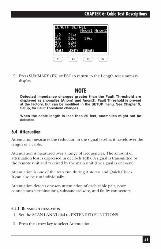
2. Press SUMMARY (F3) or ESC to return to the Length test summarydisplay.
NOTEDetected impedance changes greater than the Fault Threshold aredisplayed as anomalies (Anom1 and Anom2). Fault Threshold is pre-setat the factory, but can be modified in the SETUP menu. See Chapter 9,Setup, for Fault Threshold changes.
When the cable length is less than 20 feet, anomalies might not bedetected.
6.4 AttenuationAttenuation measures the reduction in the signal level as it travels over thelength of a cable.
Attenuation is measured over a range of frequencies. The amount ofattenuation loss is expressed in decibels (dB). A signal is transmitted by the remote unit and received by the main unit (the signal is one-way).
Attenuation is one of the tests run during Autotest and Quick Check. It can also be run individually.
Attenuation detects one-way attenuation of each cable pair, poorconnections/terminations, substandard wire, and faulty connectors.
6.4.1 RUNNING ATTENUATION
1. Set the SCAN-LAN VI dial to EXTENDED FUNCTIONS.
2. Press the arrow key to select Attenuation.
F1 F2 F3 F4
52
SCAN-LAN VI
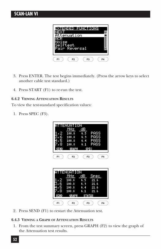
3. Press ENTER. The test begins immediately. (Press the arrow keys to selectanother cable test standard.)
4. Press START (F1) to re-run the test.
6.4.2 VIEWING ATTENUATION RESULTS
To view the test-standard specification values:
1. Press SPEC (F3).
2. Press SEND (F1) to restart the Attenuation test.
6.4.3 VIEWING A GRAPH OF ATTENUATION RESULTS
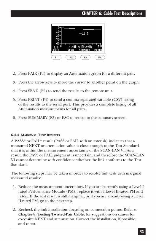
1. From the test summary screen, press GRAPH (F2) to view the graph ofthe Attenuation test results.
F1 F2 F3 F4
F1 F2 F3 F4
F1 F2 F3 F4
53
CHAPTER 6: Cable Test Descriptions
2. Press PAIR (F1) to display an Attenuation graph for a different pair.
3. Press the arrow keys to move the cursor to another point on the graph.
4. Press SEND (F2) to send the results to the remote unit.
5. Press PRINT (F4) to send a comma-separated variable (CSV) listing of the results to the serial port. This provides a complete listing of allAttenuation measurements for all pairs.
6. Press SUMMARY (F3) or ESC to return to the summary screen.
6.4.4 MARGINAL TEST RESULTS
A PASS* or FAIL* result (PASS or FAIL with an asterisk) indicates that ameasured NEXT or attenuation value is close enough to the Test Standardthat it is within the measurement uncertainty of the SCAN-LAN VI. As aresult, the PASS or FAIL judgment is uncertain, and therefore the SCAN-LANVI cannot determine with confidence whether the link conforms to the TestStandard.
The following steps may be taken in order to resolve link tests with marginalmeasured results:
1. Reduce the measurement uncertainty. If you are currently using a Level I-rated Performance Module (PM), replace it with a Level II-rated PM andretest. If the test result is still marginal, or if you are already using a LevelII-rated PM, go to the next step.
2. Recheck the link installation, focusing on connection points. Refer toChapter 8, Testing Twisted-Pair Cable, for suggestions on causes forexcessive NEXT and attenuation. Correct the installation, if possible, and retest.
F1 F2 F3 F4
54
SCAN-LAN VI
6.5 ACRAttenuation-to-Crosstalk Ratio (ACR) is the difference between crosstalk and attenuation, measured in dB, at a given frequency. ACR is computedbased on the measured values of attenuation and NEXT.
A positive ACR is necessary to assure that a signal at the receiving end of achannel is stronger than the crosstalk interference imposed from adjacentwire pairs. ACR is therefore an indication of the expected reliability of datatransmissions.
ACR is automatically computed during Autotest and Quick Check whentesting twisted-pair cable. It can also be run individually as an ExtendedFunction test.
6.5.1 RUNNING ACR
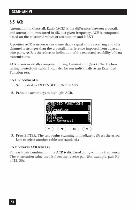
1. Set the dial to EXTENDED FUNCTIONS.
2. Press the arrow keys to highlight ACR.
3. Press ENTER. The test begins scanning immediately. (Press the arrowkeys to select another cable test standard.)
6.5.2 VIEWING ACR RESULTS
For each pair combination the ACR is displayed along with the frequency.The attenuation value used is from the receive pair (for example, pair 3,6 of 12/36).
F1 F2 F3 F4
55
CHAPTER 6: Cable Test Descriptions
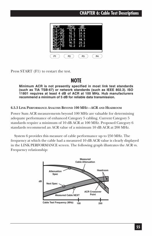
Press START (F1) to restart the test.
NOTEMinimum ACR is not presently specified in most link test standards(such as TIA TSB-67) or network standards (such as IEEE 802.3). ISO11801 requires at least 4 dB of ACR at 100 MHz. Hub manufacturersrecommend a minimum of 5 dB for reliable data transmission.
6.5.3 LINK PERFORMANCE ANALYSIS BEYOND 100 MHZ—ACR AND HEADROOM
Power Sum ACR measurements beyond 100 MHz are valuable for determiningadequate performance of enhanced Category 5 cabling. Current Category 5standards require a minimum of 10 dB ACR at 100 MHz. Proposed Category 6standards recommend an ACR value of a minimum 10 dB ACR at 200 MHz.
System 6 provides this measure of cable performance up to 250 MHz. Thefrequency at which the cable had a measured 10 dB ACR value is clearly displayedin the LINK PERFORMANCE screen. The following graph illustrates the ACR vs.Frequency relationship:
F1 F2 F3 F4

56
SCAN-LAN VI
6.6 NoiseImpulse Noise is non-repetitive electrical spikes or pulses caused by externalelectromagnetic fields. It is one of the primary causes of inconsistentperformance on unshielded twisted-pair networks.
The Noise test counts noise impulses (spikes) greater in amplitude than aminimum threshold on an idle twisted-pair cable segment and provides a report of the results.
Noise results for all selected cable types are compared to the IEEE 802.310BASE-T impulse noise specification. The default noise-threshold setting is260 mV. Refer to Chapter 9, Setup, for information on how to change thisvalue.
The Noise test reports time duration of the test, average number of impulsesin the last second, peak number of impulses in any one second, and the timeof occurrence since the start of the test.
6.6.1 RUNNING NOISE
The Noise test runs continuously until stopped by the user.
1. If testing a twisted-pair cable, connect one end of the cable under test tothe main unit and the other end to the remote unit. Set the remote unit’sdial to REMOTE.
2. Set the main unit’s dial to EXTENDED FUNCTIONS. Scroll through thelist of functions until NOISE is highlighted.
3. Press ENTER to select the test. The test begins immediately. (Press thearrow keys to change the cable test standard.)
F1 F2 F3 F4
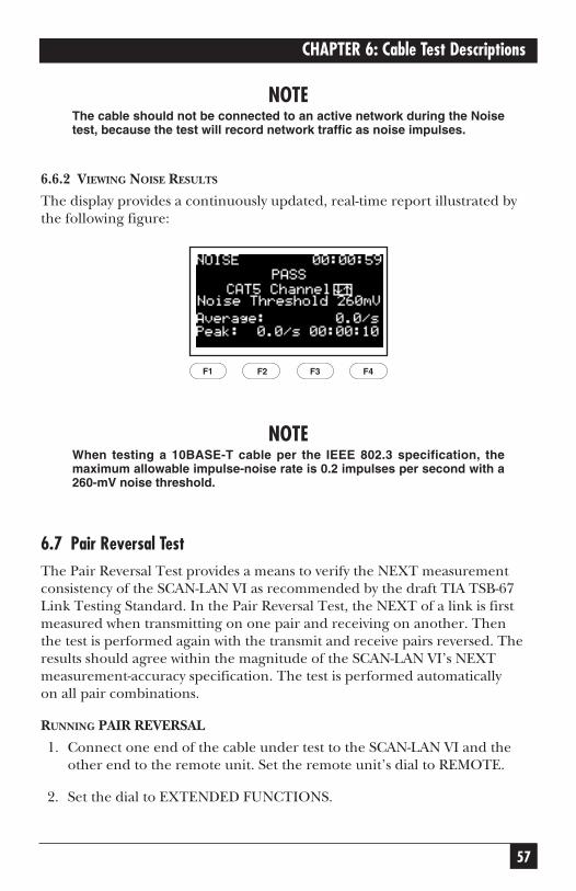
57
CHAPTER 6: Cable Test Descriptions
NOTEThe cable should not be connected to an active network during the Noisetest, because the test will record network traffic as noise impulses.
6.6.2 VIEWING NOISE RESULTS
The display provides a continuously updated, real-time report illustrated bythe following figure:
NOTEWhen testing a 10BASE-T cable per the IEEE 802.3 specification, themaximum allowable impulse-noise rate is 0.2 impulses per second with a260-mV noise threshold.
6.7 Pair Reversal TestThe Pair Reversal Test provides a means to verify the NEXT measurementconsistency of the SCAN-LAN VI as recommended by the draft TIA TSB-67Link Testing Standard. In the Pair Reversal Test, the NEXT of a link is firstmeasured when transmitting on one pair and receiving on another. Then the test is performed again with the transmit and receive pairs reversed. Theresults should agree within the magnitude of the SCAN-LAN VI’s NEXTmeasurement-accuracy specification. The test is performed automatically on all pair combinations.
RUNNING PAIR REVERSAL
1. Connect one end of the cable under test to the SCAN-LAN VI and theother end to the remote unit. Set the remote unit’s dial to REMOTE.
2. Set the dial to EXTENDED FUNCTIONS.
F1 F2 F3 F4
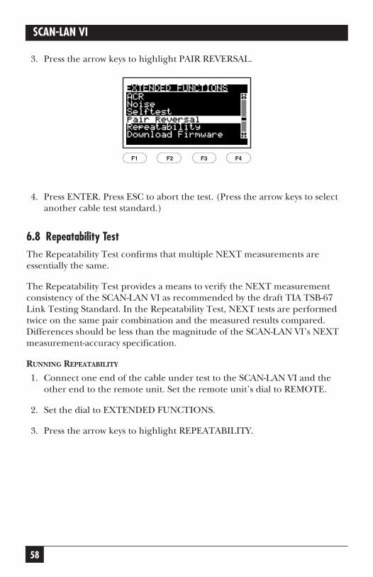
58
SCAN-LAN VI
3. Press the arrow keys to highlight PAIR REVERSAL.
4. Press ENTER. Press ESC to abort the test. (Press the arrow keys to selectanother cable test standard.)
6.8 Repeatability Test The Repeatability Test confirms that multiple NEXT measurements areessentially the same.
The Repeatability Test provides a means to verify the NEXT measurementconsistency of the SCAN-LAN VI as recommended by the draft TIA TSB-67Link Testing Standard. In the Repeatability Test, NEXT tests are performedtwice on the same pair combination and the measured results compared.Differences should be less than the magnitude of the SCAN-LAN VI’s NEXTmeasurement-accuracy specification.
RUNNING REPEATABILITY
1. Connect one end of the cable under test to the SCAN-LAN VI and theother end to the remote unit. Set the remote unit’s dial to REMOTE.
2. Set the dial to EXTENDED FUNCTIONS.
3. Press the arrow keys to highlight REPEATABILITY.
F1 F2 F3 F4

59
CHAPTER 6: Cable Test Descriptions
4. Press ENTER. Press ESC to abort the test. (Press the arrow keys to selectanother cable test standard.)
6.9 ImpedanceThe SCAN-LAN VI does not have impedance.
6.10 Cable Toner
The Cable Toner function injects an audible frequency signal on a cable toenable cable identification by a cable toner probe.
A modulated ~1 KHz signal is injected on pin one (1). Any commerciallyavailable Toner Probe can be used to identify the corresponding cable end in a remote wiring location.
RUNNING CABLE TONER
1. Connect one end of the cable under test to the SCAN-LAN VI.
2. Set the dial to EXTENDED FUNCTIONS.
3. Press the arrow keys to highlight CABLE TONER.
SEND GRAPH DETAIL SAVE
POWER SUM NEXT
F1 F2 F3 F4
1,2 PASS3,6 PASS4,5 PASS7,8 PASS
F1 F2 F3 F4
60
SCAN-LAN VI
4. Press ENTER. Press ESC to abort the test. (Press the arrow keys to selectanother cable test standard.)
NOTEWhen the AUTO TONER is ON, the toner function is activated whenever aremote is not attached and the main unit is set to Quick Check orAutotest. When a remote is attached, the toner is turned OFFautomatically and the test proceeds. This makes it easy to identify whichcable is ready to be tested next.
6.11 Delay/Delay SkewDelay is a measure of the time electrical signals take to propagate from oneend of the cable to the other end. The difference in propagation delays fromone cable pair to another is called Delay Skew.
The Delay test measures and displays the propagation delay of each wire pair.The Delay Skew test measures and displays the difference in propagationdelay from each wire pair to the shortest wire pair.
Both Delay and Delay Skew are becoming important parameters for emerginghigh-speed LAN standards such as 100BASET4, 622-Mbps ATM, and GigabitEthernet.
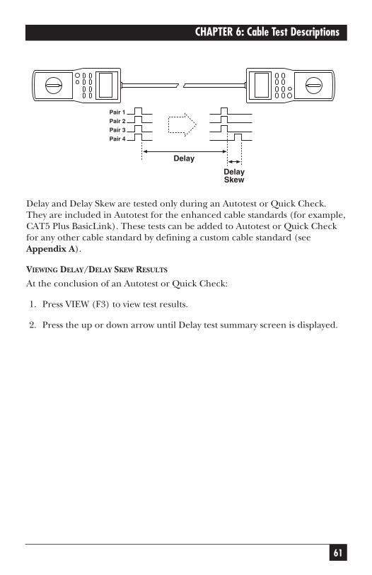
61
CHAPTER 6: Cable Test Descriptions
Delay and Delay Skew are tested only during an Autotest or Quick Check.They are included in Autotest for the enhanced cable standards (for example,CAT5 Plus BasicLink). These tests can be added to Autotest or Quick Checkfor any other cable standard by defining a custom cable standard (seeAppendix A).
VIEWING DELAY/DELAY SKEW RESULTS
At the conclusion of an Autotest or Quick Check:
1. Press VIEW (F3) to view test results.
2. Press the up or down arrow until Delay test summary screen is displayed.
Pair 1
Pair 2
Pair 3
Pair 4
Delay
DelaySkew
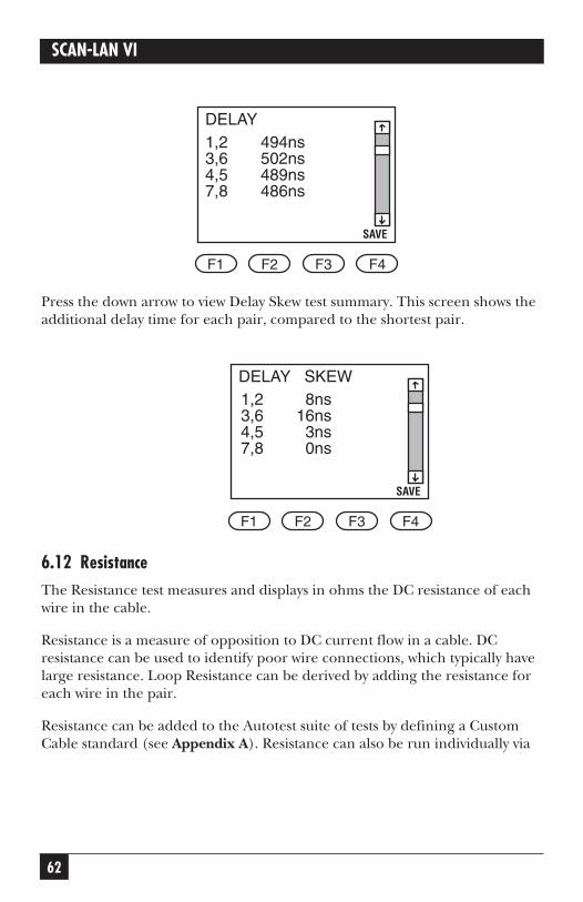
62
SCAN-LAN VI
Press the down arrow to view Delay Skew test summary. This screen shows theadditional delay time for each pair, compared to the shortest pair.
6.12 ResistanceThe Resistance test measures and displays in ohms the DC resistance of eachwire in the cable.
Resistance is a measure of opposition to DC current flow in a cable. DCresistance can be used to identify poor wire connections, which typically havelarge resistance. Loop Resistance can be derived by adding the resistance foreach wire in the pair.
Resistance can be added to the Autotest suite of tests by defining a CustomCable standard (see Appendix A). Resistance can also be run individually via
SAVE
DELAY SKEW
F1 F2 F3 F4
1,2 8ns3,6 16ns4,5 3ns7,8 0ns
SAVE
DELAY
F1 F2 F3 F4
1,2 494ns3,6 502ns4,5 489ns7,8 486ns
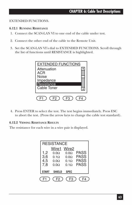
63
CHAPTER 6: Cable Test Descriptions
EXTENDED FUNCTIONS.
6.12.1 RUNNING RESISTANCE
1. Connect the SCAN-LAN VI to one end of the cable under test.
2. Connect the other end of the cable to the Remote Unit.
3. Set the SCAN-LAN VI’s dial to EXTENDED FUNCTIONS. Scroll throughthe list of functions until RESISTANCE is highlighted.
4. Press ENTER to select the test. The test begins immediately. Press ESC to abort the test. (Press the arrow keys to change the cable test standard).
6.12.2 VIEWING RESISTANCE RESULTS
The resistance for each wire in a wire pair is displayed.
START SHIELD SPEC
RESISTANCE
F1 F2 F3 F4
1,23,64,57,8
0.0Ω0.1Ω0.0Ω0.0Ω
Wire1 Wire2PASSPASSPASSPASS
0.0Ω0.0Ω0.1Ω0.1Ω
F1 F2 F3 F4
AttenuationACRNoiseImpedanceResistanceCable Toner
EXTENDED FUNCTIONS
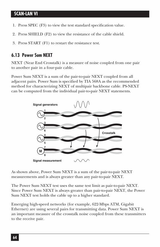
64
SCAN-LAN VI
1. Press SPEC (F3) to view the test standard specification value.
2. Press SHIELD (F2) to view the resistance of the cable shield.
3. Press START (F1) to restart the resistance test.
6.13 Power Sum NEXTNEXT (Near End Crosstalk) is a measure of noise coupled from one pair to another pair in a four-pair cable.
Power Sum NEXT is a sum of the pair-to-pair NEXT coupled from alladjacent pairs. Power Sum is specified by TIA 568A as the recommendedmethod for characterizing NEXT of multipair backbone cable. PS-NEXTcan be computed from the individual pair-to-pair NEXT statements.
As shown above, Power Sum NEXT is a sum of the pair-to-pair NEXTmeasurements and is always greater than any pair-to-pair NEXT.
The Power Sum NEXT test uses the same test limit as pair-to-pair NEXT.Since Power Sum NEXT is always greater than pair-to-pair NEXT, the PowerSum NEXT test holds the cable up to a higher standard.
Emerging high-speed networks (for example, 622-Mbps ATM, GigabitEthernet) are using several pairs for transmitting data. Power Sum NEXT isan important measure of the crosstalk noise coupled from these transmittersto the receive pair.
M
Signal measurement
Signal generators
7
8
4
5
3
6
1
2
Crosstalk
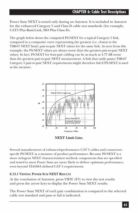
65
CHAPTER 6: Cable Test Descriptions
Power Sum NEXT is tested only during an Autotest. It is included in Autotestfor the enhanced Category 5 and Class D cable test standards (for example,CAT5 Plus BasicLink, ISO Plus Class D).
The graph below shows the computed PS-NEXT for a typical Category 5 link,compared to a composite curve representing the greatest (i.e. closest to the TSB-67 NEXT limit) pair-to-pair NEXT values for the same link. As seen from thisexample, the PS-NEXT values are always worse than the greatest pair-to-pair NEXTvalues. In fact, PS-NEXT for four-pair cabling can be as much as 4.77 dB worsethan the greatest pair-to-pair NEXT measurement. A link that easily passes TSB-67Category 5 pair-to-pair NEXT requirements might therefore fail if PS-NEXT is usedas the measure.
NEXT Limit Line.
Several manufacturers of enhanced-performance CAT 5 cables and connectorsspecify PS-NEXT as a measure of product performance. Because PS-NEXT is amore stringent NEXT characterization method, components that are specified and tested to meet Power Sum are more likely to deliver optimum performance,even beyond TIA568A defined CAT 5 requirements.
6.13.1 VIEWING POWER SUM NEXT RESULTS
At the conclusion of Autotest, press VIEW (F3) to view the test results and press the arrow keys to display the Power Sum NEXT results.
The Power Sum NEXT of each pair combination is compared to the selectedcable test standard and pass or fail is indicated.
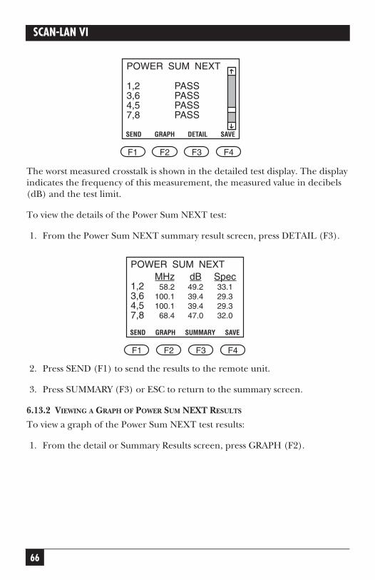
66
SCAN-LAN VI
The worst measured crosstalk is shown in the detailed test display. The displayindicates the frequency of this measurement, the measured value in decibels(dB) and the test limit.
To view the details of the Power Sum NEXT test:
1. From the Power Sum NEXT summary result screen, press DETAIL (F3).
2. Press SEND (F1) to send the results to the remote unit.
3. Press SUMMARY (F3) or ESC to return to the summary screen.
6.13.2 VIEWING A GRAPH OF POWER SUM NEXT RESULTS
To view a graph of the Power Sum NEXT test results:
1. From the detail or Summary Results screen, press GRAPH (F2).
SEND GRAPH SUMMARY SAVE
POWER SUM NEXT
F1 F2 F3 F4
1,23,64,57,8
58.2100.1100.168.4
MHz49.239.439.447.0
dB33.129.329.332.0
Spec
SEND GRAPH DETAIL SAVE
POWER SUM NEXT
F1 F2 F3 F4
1,2 PASS3,6 PASS4,5 PASS7,8 PASS
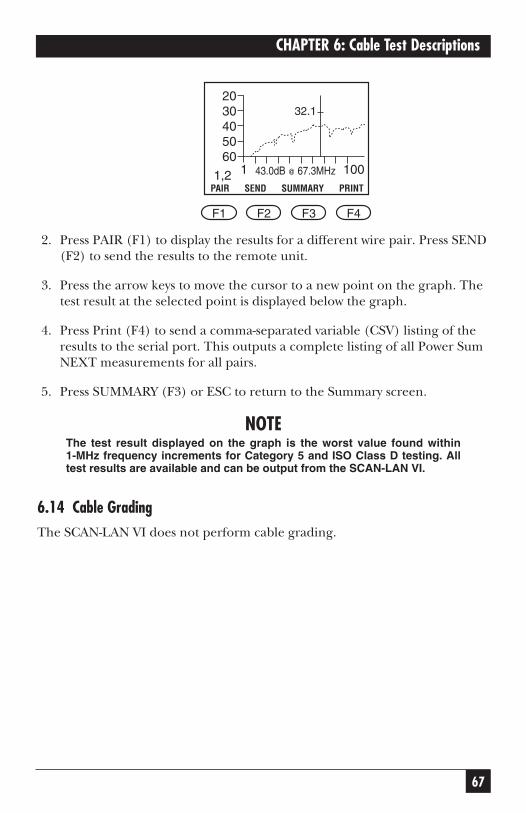
67
CHAPTER 6: Cable Test Descriptions
2. Press PAIR (F1) to display the results for a different wire pair. Press SEND(F2) to send the results to the remote unit.
3. Press the arrow keys to move the cursor to a new point on the graph. Thetest result at the selected point is displayed below the graph.
4. Press Print (F4) to send a comma-separated variable (CSV) listing of theresults to the serial port. This outputs a complete listing of all Power SumNEXT measurements for all pairs.
5. Press SUMMARY (F3) or ESC to return to the Summary screen.
NOTEThe test result displayed on the graph is the worst value found within 1-MHz frequency increments for Category 5 and ISO Class D testing. Alltest results are available and can be output from the SCAN-LAN VI.
6.14 Cable GradingThe SCAN-LAN VI does not perform cable grading.
PAIR SEND SUMMARY PRINT
F1 F2 F3 F4
1
2030405060
1,2 10043.0dB @ 67.3MHz
32.1
68
SCAN-LAN VI
7. Printing, Uploading, andViewing Test Results
The Print function allows you to send test results to a serial printer, uploadthe test results to a PC, or view stored test reports before printing oruploading.
The Print function allows you to: Print some or all of the saved reports, print the last Traffic Report, delete saved reports, and view saved reports.
7.1 Connecting to a PC or Printer7.1.1 OVERVIEW
Connect the single, 9-pin connector end of the PC Interface Cable to theserial port on the SCAN-LAN VI. Connect one of the connectors on the other end (use either the 9- or the 25-pin connector) to a printer or PC.
NOTEMake sure you do not leave the unit connected to the PC while makingmeasurements. Doing so may cause a Wire Map Fail error to occur.
7.1.2 ADAPTER/CONNECTOR INFORMATION
The PC Interface Cable (supplied) may not be the correct connector toproperly connect to all serial printers. Use only straight-through adapters to connect the PC Interface Cable to a printer.
Connectors with different pin assignments than those mentioned above mayaffect output operation (see Chapter 1, Specifications, for the Serial Port pinassignments).
7.2 Printing/Uploading Test Results7.2.1 PRINTING/UPLOADING A SINGLE TEST REPORT
1. Set dial to PRINT to display the Print menu.
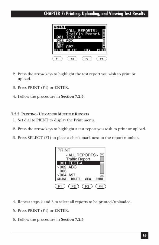
69
CHAPTER 7: Printing, Uploading, and Viewing Test Results
2. Press the arrow keys to highlight the test report you wish to print orupload.
3. Press PRINT (F4) or ENTER.
4. Follow the procedure in Section 7.2.5.
7.2.2 PRINTING/UPLOADING MULTIPLE REPORTS
1. Set dial to PRINT to display the Print menu.
2. Press the arrow keys to highlight a test report you wish to print or upload.
3. Press SELECT (F1) to place a check mark next to the report number.
4. Repeat steps 2 and 3 to select all reports to be printed/uploaded.
5. Press PRINT (F4) or ENTER.
6. Follow the procedure in Section 7.2.5.
√
√
<ALL REPORTS>Traffic Report
SELECT DELETE VIEW PRINT
F1 F2 F3 F4
001 TEST-A002 ABC003004 A97
F1 F2 F3 F4
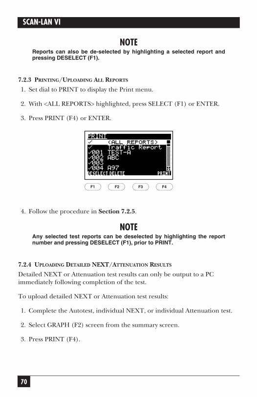
70
SCAN-LAN VI
NOTEReports can also be de-selected by highlighting a selected report andpressing DESELECT (F1).
7.2.3 PRINTING/UPLOADING ALL REPORTS
1. Set dial to PRINT to display the Print menu.
2. With <ALL REPORTS> highlighted, press SELECT (F1) or ENTER.
3. Press PRINT (F4) or ENTER.
4. Follow the procedure in Section 7.2.5.
NOTEAny selected test reports can be deselected by highlighting the reportnumber and pressing DESELECT (F1), prior to PRINT.
7.2.4 UPLOADING DETAILED NEXT/ATTENUATION RESULTS
Detailed NEXT or Attenuation test results can only be output to a PCimmediately following completion of the test.
To upload detailed NEXT or Attenuation test results:
1. Complete the Autotest, individual NEXT, or individual Attenuation test.
2. Select GRAPH (F2) screen from the summary screen.
3. Press PRINT (F4).
F1 F2 F3 F4
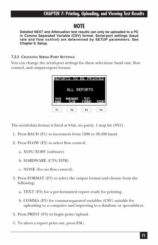
71
CHAPTER 7: Printing, Uploading, and Viewing Test Results
NOTEDetailed NEXT and Attenuation test results can only be uploaded to a PCin Comma Separated Variable (CSV) format. Serial-port settings (baudrate and flow control) are determined by SETUP parameters. SeeChapter 9, Setup.
7.2.5 CHANGING SERIAL-PORT SETTINGS
You can change the serial-port settings for these selections: baud rate, flowcontrol, and output-report format.
The serial-data format is fixed at 8-bit, no parity, 1 stop bit (8N1).
1. Press BAUD (F1) to increment from 1200 to 38,400 baud.
2. Press FLOW (F2) to select flow control:
a. XON/XOFF (software)
b. HARDWARE (CTS/DTR)
c. NONE (for no flow control).
3. Press FORMAT (F3) to select the output format and choose from thefollowing:
a. TEXT (F3) for a pre-formatted report ready for printing.
b. COMMA (F3) for comma-separated variables (CSV) suitable foruploading to a computer and importing to a database or spreadsheet.
4. Press PRINT (F4) to begin print/upload.
5. To abort a report print out, press ESC.
F1 F2 F3 F4

72
SCAN-LAN VI
NOTESerial-port setting changes are automatically stored in nonvolatilememory.
7.2.6 SAMPLE 250 MHZ UTP AUTOTEST REPORT
Up to 450 test reports can be saved in each SCAN-LAN System 6 tester. Reports canbe uploaded to a PC and viewed or printed with the Report Manager software.
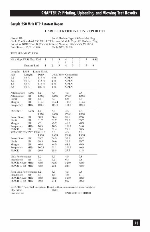
73
CHAPTER 7: Printing, Uploading, and Viewing Test Results
Sample 250 MHz UTP Autotest Report
CABLE CERTIFICATION REPORT #1
Circuit ID: Local Module Type: C6 Modular PlugCable Test Standard: 250 MHz UTPRemote Module Type: C6 Modular PlugLocation: BUILDING D, FLOOR 6 Serial Number: 98XXXXX V8.80D4Date Tested: 05/01/1998 Cable NVP: 72.0%
TEST SUMMARY: PASS__________________________________________________________________Wire Map: PASS Near End 1 2 3 4 5 6 7 8 Sld
| | | | | | | |Remote End 1 2 3 4 5 6 7 8
__________________________________________________________________Length: PASS Limit: 308 ft.Pair Length Delay Delay Skew Comments1.2 85 ft. 116 ns 0 ns OPEN3.6 86 ft. 118 ns 2 ns OPEN4.5 85 ft. 118 ns 2 ns OPEN7.8 86 ft. 120 ns 4 ns OPEN__________________________________________________________________Attenuation: PASS 1.2 3.6 4.5 7.8Attenuation dB PASS PASS PASS PASSLimit dB 6.0 6.0 6.0 6.0Margin dB +15.6 +15.4 +15.4 +15.5Frequency MHz 101.0 101.0 101.0 101.0__________________________________________________________________PSNEXT: PASS 1.2 3.6 4.5 7.8
PASS PASS PASS PASSPower Sum dB 38.3 36.4 35.6 42.6Limit dB 31.2 31.2 29.3 33.7Margin dB +7.1 +5.2 +6.3 +8.9Frequency MHz 76.5 76.5 100.1 54.0PSACR dB 33.4 31.4 29.6 38.5REMOTE PSNEXT: PASS 1.2 3.6 4.5 7.8
PASS PASS PASS PASSPower Sum dB 35.7 34.5 33.5 45.2Limit dB 29.3 30.0 29.3 35.7Margin dB +6.4 +4.5 +4.2 +9.5Frequency MHz 100.1 91.1 100.1 40.5PSACR dB 29.9 28.8 27.7 41.8__________________________________________________________________Link Performance 1.2 3.6 4.5 7.8Headroom dB 7.3 5.2 6.3 9.8PSACR Xover MHz >250 >250 >250 >250PSACR 10 dB MHz >250 232 244 >250
Rem Link Performance 1.2 3.6 4.5 7.8Headroom dB 6.4 4.5 4.2 11.1PSACR Xover MHz >250 >250 >250 >250PSACR 10 dB MHz >250 214 227 >250__________________________________________________________________<<NOTE: *Pass/Fail uncertain. Result within measurement uncertainty.>>Operator:___________________ Date:____________________Comments: END REPORT #DR-01
74
SCAN-LAN VI
7.3 Deleting Test ReportsReports may be deleted from memory by performing these steps:
1. Set the dial to PRINT to display the Print menu screen.
2. Press the arrow keys to highlight the test report you wish to delete.
3. Press SELECT (F1) to select specific reports to be deleted. A check markappears next to the report number.
NOTETo select all reports for deletion, press SELECT (F1) when <ALLREPORTS> is highlighted. This selects all of the report numbers.
4. Press DELETE (F2). A screen displays the selected report numbers andasks you to confirm that you wish to delete the tests. (If no reports wereselected, the highlighted report is selected for deletion.)
5. Press OK (F4) or ENTER to delete the report. After the report is deleted,the unit returns to the Print screen.
or
To cancel the DELETE, press CANCEL (F1) or ESC and return to thePrint screen.
7.4 Viewing Saved Test ReportsTo review a saved report:
1. Set dial to PRINT to display the Print menu screen.
2. Press the arrow keys to highlight the number of the test report you wish to view.
3. Press VIEW (F3) to view the report.
4. Press the arrow keys to view different test results.
5. Press ESC to return to the Print menu screen.
NOTERefer to Chapter 6, Cable Test Descriptions, for more information oninterpreting test result screens.
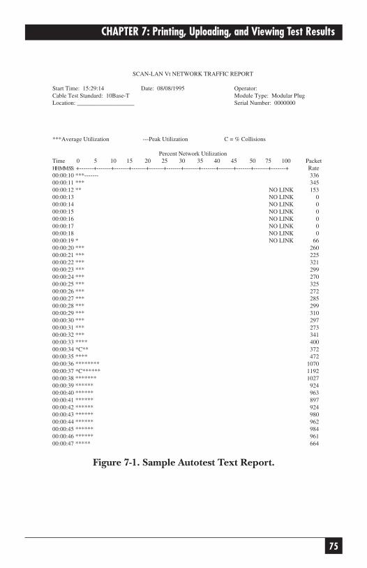
75
CHAPTER 7: Printing, Uploading, and Viewing Test Results
Figure 7-1. Sample Autotest Text Report.
SCAN-LAN Vt NETWORK TRAFFIC REPORT
Start Time: 15:29:14 Date: 08/08/1995 Operator:Cable Test Standard: 10Base-T Module Type: Modular PlugLocation: ___________________ Serial Number: 0000000
***Average Utilization ---Peak Utilization C = % Collisions
Percent Network UtilizationTime 0 5 10 15 20 25 30 35 40 45 50 75 100 PacketHH:MM:SS: +-------+-------+-------+-------+-------+-------+-------+-------+-------+-------+-------+-------+ Rate00:00:10 ***------- 33600:00:11 *** 34500:00:12 ** NO LINK 15300:00:13 NO LINK 000:00:14 NO LINK 000:00:15 NO LINK 000:00:16 NO LINK 000:00:17 NO LINK 000:00:18 NO LINK 000:00:19 * NO LINK 6600:00:20 *** 26000:00:21 *** 22500:00:22 *** 32100:00:23 *** 29900:00:24 *** 27000:00:25 *** 32500:00:26 *** 27200:00:27 *** 28500:00:28 *** 29900:00:29 *** 31000:00:30 *** 29700:00:31 *** 27300:00:32 *** 34100:00:33 **** 40000:00:34 *C** 37200:00:35 **** 47200:00:36 ******** 107000:00:37 *C****** 119200:00:38 ******* 102700:00:39 ****** 92400:00:40 ****** 96300:00:41 ****** 89700:00:42 ****** 92400:00:43 ****** 98000:00:44 ****** 96200:00:45 ****** 98400:00:46 ****** 96100:00:47 ***** 664
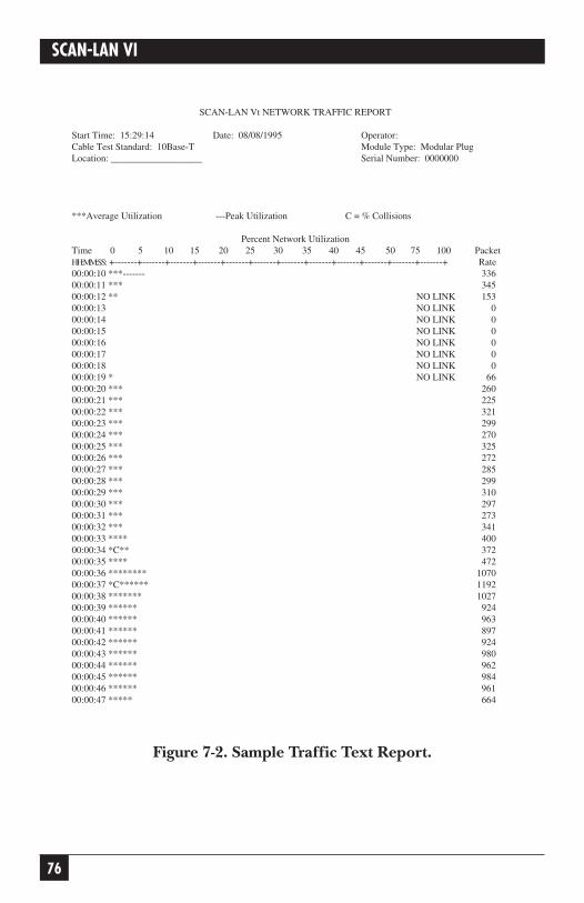
76
SCAN-LAN VI
Figure 7-2. Sample Traffic Text Report.
SCAN-LAN Vt NETWORK TRAFFIC REPORT
Start Time: 15:29:14 Date: 08/08/1995 Operator:Cable Test Standard: 10Base-T Module Type: Modular PlugLocation: ___________________ Serial Number: 0000000
***Average Utilization ---Peak Utilization C = % Collisions
Percent Network UtilizationTime 0 5 10 15 20 25 30 35 40 45 50 75 100 PacketHH:MM:SS: +-------+-------+-------+-------+-------+-------+-------+-------+-------+-------+-------+-------+ Rate00:00:10 ***------- 33600:00:11 *** 34500:00:12 ** NO LINK 15300:00:13 NO LINK 000:00:14 NO LINK 000:00:15 NO LINK 000:00:16 NO LINK 000:00:17 NO LINK 000:00:18 NO LINK 000:00:19 * NO LINK 6600:00:20 *** 26000:00:21 *** 22500:00:22 *** 32100:00:23 *** 29900:00:24 *** 27000:00:25 *** 32500:00:26 *** 27200:00:27 *** 28500:00:28 *** 29900:00:29 *** 31000:00:30 *** 29700:00:31 *** 27300:00:32 *** 34100:00:33 **** 40000:00:34 *C** 37200:00:35 **** 47200:00:36 ******** 107000:00:37 *C****** 119200:00:38 ******* 102700:00:39 ****** 92400:00:40 ****** 96300:00:41 ****** 89700:00:42 ****** 92400:00:43 ****** 98000:00:44 ****** 96200:00:45 ****** 98400:00:46 ****** 96100:00:47 ***** 664
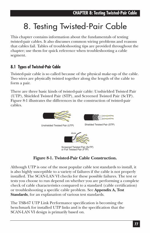
77
CHAPTER 8: Testing Twisted-Pair Cable
8. Testing Twisted-Pair CableThis chapter contains information about the fundamentals of testingtwisted-pair cables. It also discusses common wiring problems and reasonsthat cables fail. Tables of troubleshooting tips are provided throughout thechapter; use them for quick reference when troubleshooting a cablesegment.
8.1 Types of Twisted-Pair Cable
Twisted-pair cable is so called because of the physical make-up of the cable.Two wires are physically twisted together along the length of the cable toform a pair.
There are three basic kinds of twisted-pair cable: Unshielded Twisted Pair(UTP), Shielded Twisted Pair (STP), and Screened Twisted Pair (ScTP).Figure 8-1 illustrates the differences in the construction of twisted-paircables.
Figure 8-1. Twisted-Pair Cable Construction.
Although UTP is one of the most popular cable test standards to install, itis also highly susceptible to a variety of failures if the cable is not properlyinstalled. The SCAN-LAN VI checks for these possible failures. The test ortests you choose to run depend on whether you are performing a completecheck of cable characteristics compared to a standard (cable certification)or troubleshooting a specific cable problem. See Appendix A, TestStandards, for an explanation of various test standards.
The TSB-67 UTP Link Performance specification is becoming thebenchmark for installed UTP links and is the specification that the SCAN-LAN VI design is primarily based on.
Unshielded Twisted Pair (UTP)
Shielded Twisted Pair (STP)
Screened Twisted Pair (ScTP)or Foil Twisted Pair (FTP)
drain
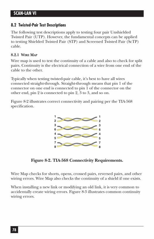
78
SCAN-LAN VI
8.2 Twisted-Pair Test Descriptions
The following test descriptions apply to testing four pair UnshieldedTwisted Pair (UTP). However, the fundamental concepts can be applied to testing Shielded Twisted Pair (STP) and Screened Twisted Pair (ScTP)cable.
8.2.1 WIRE MAP
Wire map is used to test the continuity of a cable and also to check for splitpairs. Continuity is the electrical connection of a wire from one end of thecable to the other.
Typically when testing twisted-pair cable, it’s best to have all wiresconnected straight-through. Straight-through means that pin 1 of theconnector on one end is connected to pin 1 of the connector on the other end, pin 2 is connected to pin 2, 3 to 3, and so on.
Figure 8-2 illustrates correct connectivity and pairing per the TIA-568specification.
Figure 8-2. TIA-568 Connectivity Requirements.
Wire Map checks for shorts, opens, crossed pairs, reversed pairs, and otherwiring errors. Wire Map also checks the continuity of a shield if one exists.
When installing a new link or modifying an old link, it is very common toaccidentally create wiring errors. Figure 8-3 illustrates common continuitywiring errors.
12364578
12364578
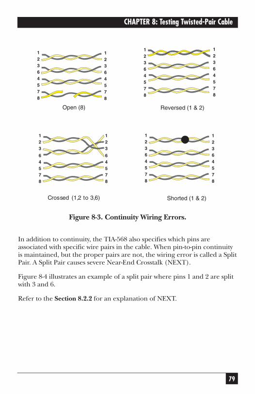
79
CHAPTER 8: Testing Twisted-Pair Cable
Figure 8-3. Continuity Wiring Errors.
In addition to continuity, the TIA-568 also specifies which pins areassociated with specific wire pairs in the cable. When pin-to-pin continuityis maintained, but the proper pairs are not, the wiring error is called a SplitPair. A Split Pair causes severe Near-End Crosstalk (NEXT).
Figure 8-4 illustrates an example of a split pair where pins 1 and 2 are splitwith 3 and 6.
Refer to the Section 8.2.2 for an explanation of NEXT.
12364578
12364578
12364578
12364578
Open (8) Reversed (1 & 2)
12364578
12364578
Shorted (1 & 2)
123
64578
123
64578
Crossed (1,2 to 3,6)
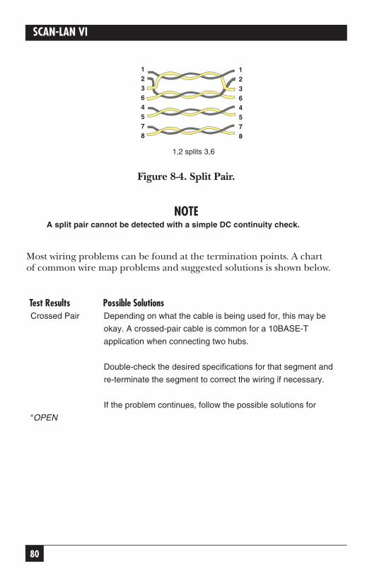
80
SCAN-LAN VI
Figure 8-4. Split Pair.
NOTEA split pair cannot be detected with a simple DC continuity check.
Most wiring problems can be found at the termination points. A chart of common wire map problems and suggested solutions is shown below.
Test Results Possible SolutionsCrossed Pair Depending on what the cable is being used for, this may be
okay. A crossed-pair cable is common for a 10BASE-T
application when connecting two hubs.
Double-check the desired specifications for that segment and
re-terminate the segment to correct the wiring if necessary.
If the problem continues, follow the possible solutions for
“OPEN
12364578
12364578
1,2 splits 3,6
81
CHAPTER 8: Testing Twisted-Pair Cable
on one or more of the pairs” on the next page.
Test Results Possible SolutionsOPEN on one or Perform a length test to locate fault. Go to the fault and correct
more of the pairs the wiring error.
If you cannot locate the fault by the length test, check all ter-
minations at punchdown blocks, patch panels, and wall plates.
If no miswires are found, back up to the next-closest
telecommunication outlet or transition point and test from there.
Continue to the next outlet or transition point until fault the
is isolated. Then reterminate the segment.
If the problem continues, it could be a damaged cable.
SHORT on one or Follow same procedure as for “OPEN on one or more of the
more of the pairs pairs.”
Remote unit Be sure that the main and remote units are connected to the
not connected same cable.
If the connections are correct, follow same procedure as
searching for “OPEN on one or more of the pairs.”
Reversed pair Depending on the application, this may be okay.
Double-check the specification you are testing to and
re-terminate the segment if necessary to correct the problem.
If the problem continues, follow the procedure for “OPEN on
one or more of the pairs” to locate fault.
Split pair Make note of which pairs are split. Double-check the
requirements (which conductors should be paired) for the
segment under test.
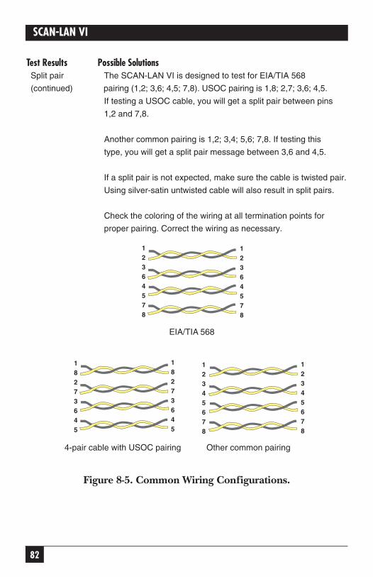
82
SCAN-LAN VI
Test Results Possible SolutionsSplit pair The SCAN-LAN VI is designed to test for EIA/TIA 568
(continued) pairing (1,2; 3,6; 4,5; 7,8). USOC pairing is 1,8; 2,7; 3,6; 4,5.
If testing a USOC cable, you will get a split pair between pins
1,2 and 7,8.
Another common pairing is 1,2; 3,4; 5,6; 7,8. If testing this
type, you will get a split pair message between 3,6 and 4,5.
If a split pair is not expected, make sure the cable is twisted pair.
Using silver-satin untwisted cable will also result in split pairs.
Check the coloring of the wiring at all termination points for
proper pairing. Correct the wiring as necessary.
Figure 8-5. Common Wiring Configurations.
4-pair cable with USOC pairing Other common pairing
18273645
12345678
12345678
12364578
12364578
EIA/TIA 568
18273645
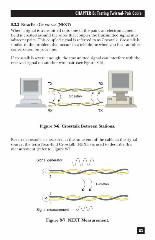
83
CHAPTER 8: Testing Twisted-Pair Cable
8.2.2 NEAR-END CROSSTALK (NEXT)When a signal is transmitted onto one of the pairs, an electromagneticfield is created around the wires that couples the transmitted signal intoadjacent pairs. This coupled signal is referred to as Crosstalk. Crosstalk issimilar to the problem that occurs in a telephone when you hear anotherconversation on your line.
If crosstalk is severe enough, the transmitted signal can interfere with thereceived signal on another wire pair (see Figure 8-6).
Figure 8-6. Crosstalk Between Stations.
Because crosstalk is measured at the same end of the cable as the signalsource, the term Near-End Crosstalk (NEXT) is used to describe thismeasurement (refer to Figure 8-7).
Figure 8-7. NEXT Measurement.
1
2
3
4M
Crosstalk
Signal measurement
Signal generator
XT
XR
XR
XT
crosstalk
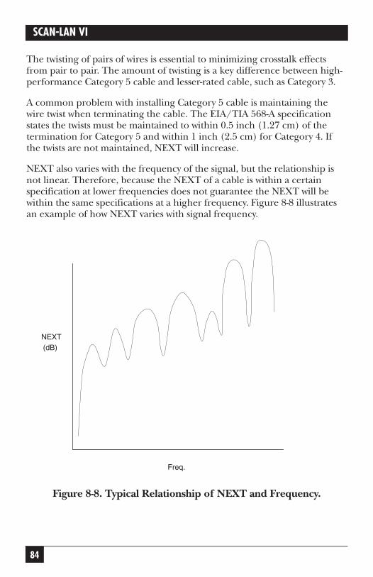
84
SCAN-LAN VI
The twisting of pairs of wires is essential to minimizing crosstalk effectsfrom pair to pair. The amount of twisting is a key difference between high-performance Category 5 cable and lesser-rated cable, such as Category 3.
A common problem with installing Category 5 cable is maintaining thewire twist when terminating the cable. The EIA/TIA 568-A specificationstates the twists must be maintained to within 0.5 inch (1.27 cm) of thetermination for Category 5 and within 1 inch (2.5 cm) for Category 4. Ifthe twists are not maintained, NEXT will increase.
NEXT also varies with the frequency of the signal, but the relationship isnot linear. Therefore, because the NEXT of a cable is within a certainspecification at lower frequencies does not guarantee the NEXT will bewithin the same specifications at a higher frequency. Figure 8-8 illustratesan example of how NEXT varies with signal frequency.
Figure 8-8. Typical Relationship of NEXT and Frequency.
Freq.
NEXT(dB)
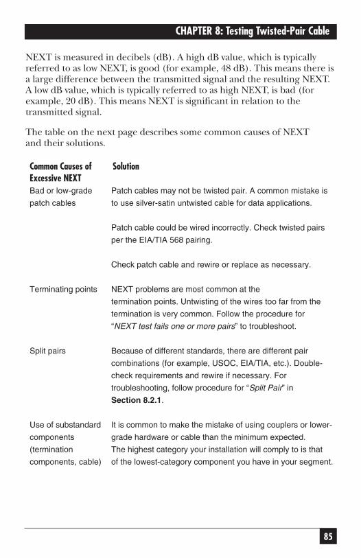
85
CHAPTER 8: Testing Twisted-Pair Cable
NEXT is measured in decibels (dB). A high dB value, which is typicallyreferred to as low NEXT, is good (for example, 48 dB). This means there isa large difference between the transmitted signal and the resulting NEXT.A low dB value, which is typically referred to as high NEXT, is bad (forexample, 20 dB). This means NEXT is significant in relation to thetransmitted signal.
The table on the next page describes some common causes of NEXT and their solutions.
Common Causes of SolutionExcessive NEXTBad or low-grade Patch cables may not be twisted pair. A common mistake is
patch cables to use silver-satin untwisted cable for data applications.
Patch cable could be wired incorrectly. Check twisted pairs
per the EIA/TIA 568 pairing.
Check patch cable and rewire or replace as necessary.
Terminating points NEXT problems are most common at the
termination points. Untwisting of the wires too far from the
termination is very common. Follow the procedure for
“NEXT test fails one or more pairs” to troubleshoot.
Split pairs Because of different standards, there are different pair
combinations (for example, USOC, EIA/TIA, etc.). Double-
check requirements and rewire if necessary. For
troubleshooting, follow procedure for “Split Pair” in
Section 8.2.1.
Use of substandard It is common to make the mistake of using couplers or lower-
components grade hardware or cable than the minimum expected.
(termination The highest category your installation will comply to is that
components, cable) of the lowest-category component you have in your segment.

86
SCAN-LAN VI
The following troubleshooting table describes some common NEXTproblems and some solutions.
Test Results Possible SolutionsNEXT test fails for one Compare test results to actual expected values to
or more pairs confirm misconformance.
Start at tester end and check that all cable is
minimum required grade.
Check termination hardware to make sure all hardware
is at least the minimum grade expected. For example,
if testing for Category 3, you could use Category 3,
4, or 5 components. If testing to Category 5, you can
only use Category 5 components.
Check that termination points meet installation standards.
Reference the specification you are using.
Re-terminate all connections as necessary.
Run Wire Map to check for split pairs. Follow procedure
for “Split Pair” in Wire Map section.
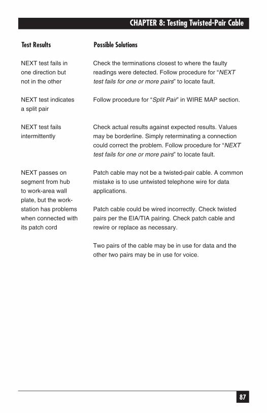
87
CHAPTER 8: Testing Twisted-Pair Cable
Test Results Possible Solutions
NEXT test fails in Check the terminations closest to where the faulty
one direction but readings were detected. Follow procedure for “NEXT
not in the other test fails for one or more pairs” to locate fault.
NEXT test indicates Follow procedure for “Split Pair” in WIRE MAP section.
a split pair
NEXT test fails Check actual results against expected results. Values
intermittently may be borderline. Simply reterminating a connection
could correct the problem. Follow procedure for “NEXT
test fails for one or more pairs” to locate fault.
NEXT passes on Patch cable may not be a twisted-pair cable. A common
segment from hub mistake is to use untwisted telephone wire for data
to work-area wall applications.
plate, but the work-
station has problems Patch cable could be wired incorrectly. Check twisted
when connected with pairs per the EIA/TIA pairing. Check patch cable and
its patch cord rewire or replace as necessary.
Two pairs of the cable may be in use for data and the
other two pairs may be in use for voice.
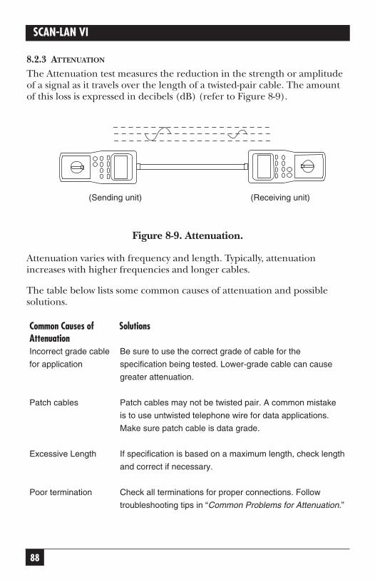
88
SCAN-LAN VI
8.2.3 ATTENUATION
The Attenuation test measures the reduction in the strength or amplitudeof a signal as it travels over the length of a twisted-pair cable. The amountof this loss is expressed in decibels (dB) (refer to Figure 8-9).
Figure 8-9. Attenuation.
Attenuation varies with frequency and length. Typically, attenuationincreases with higher frequencies and longer cables.
The table below lists some common causes of attenuation and possiblesolutions.
Common Causes of SolutionsAttenuationIncorrect grade cable Be sure to use the correct grade of cable for the
for application specification being tested. Lower-grade cable can cause
greater attenuation.
Patch cables Patch cables may not be twisted pair. A common mistake
is to use untwisted telephone wire for data applications.
Make sure patch cable is data grade.
Excessive Length If specification is based on a maximum length, check length
and correct if necessary.
Poor termination Check all terminations for proper connections. Follow
troubleshooting tips in “Common Problems for Attenuation.”
(Sending unit) (Receiving unit)
89
CHAPTER 8: Testing Twisted-Pair Cable
Common Causes of SolutionsAttenuationImpedance A splice in the segment, or damage to a segment, can
Anomalies cause excess attenuation.
Perform a length test to check for anomalies in the segment.
If anomaly is detected, go to that point and examine the
cable and connections for kinks, cuts, splices, incorrect
cable, sharp bends, etc. Repair as necessary.
Substandard It is common to make the mistake of using couplers or
components lower-grade hardware or cable than the minimum
expected. The highest category your installation will comply
to is that of the lowest-category component in your segment.
The chart below describes some attenuation problems and their possiblesolutions.
Test Results Possible SolutionsAttenuation test Compare actual to expected values to confirm misconformance.
fails for one or
more pairs Check that the length is within specification in applications
where attenuation is a maximum limit only. If the cable is too long,
correct as necessary.
If attenuation is based on a per-foot limit, follow the procedure for
“NEXT test fails one or more pairs” to locate the attenuation problem.
Attenuation Compare actual results to expected results. Values may be
test fails borderline.
intermittently
Re-terminating a connection could correct the problem.
Follow the procedure for “NEXT test fails for one or more pairs”
to locate the fault.
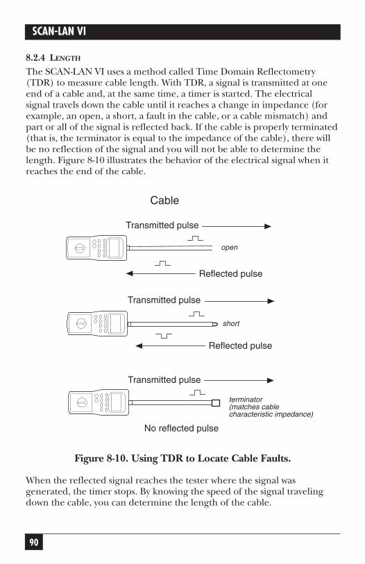
90
SCAN-LAN VI
8.2.4 LENGTH
The SCAN-LAN VI uses a method called Time Domain Reflectometry(TDR) to measure cable length. With TDR, a signal is transmitted at oneend of a cable and, at the same time, a timer is started. The electrical signal travels down the cable until it reaches a change in impedance (forexample, an open, a short, a fault in the cable, or a cable mismatch) andpart or all of the signal is reflected back. If the cable is properly terminated(that is, the terminator is equal to the impedance of the cable), there willbe no reflection of the signal and you will not be able to determine thelength. Figure 8-10 illustrates the behavior of the electrical signal when itreaches the end of the cable.
Figure 8-10. Using TDR to Locate Cable Faults.
When the reflected signal reaches the tester where the signal wasgenerated, the timer stops. By knowing the speed of the signal travelingdown the cable, you can determine the length of the cable.
Transmitted pulse
Reflected pulse
Cable
Transmitted pulse
Reflected pulse
open
short
Transmitted pulse
No reflected pulse
terminator(matches cable characteristic impedance)
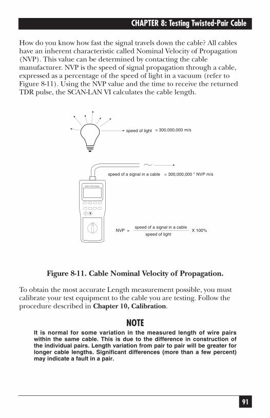
91
CHAPTER 8: Testing Twisted-Pair Cable
How do you know how fast the signal travels down the cable? All cableshave an inherent characteristic called Nominal Velocity of Propagation(NVP). This value can be determined by contacting the cablemanufacturer. NVP is the speed of signal propagation through a cable,expressed as a percentage of the speed of light in a vacuum (refer toFigure 8-11). Using the NVP value and the time to receive the returnedTDR pulse, the SCAN-LAN VI calculates the cable length.
Figure 8-11. Cable Nominal Velocity of Propagation.
To obtain the most accurate Length measurement possible, you mustcalibrate your test equipment to the cable you are testing. Follow theprocedure described in Chapter 10, Calibration.
NOTEIt is normal for some variation in the measured length of wire pairswithin the same cable. This is due to the difference in construction ofthe individual pairs. Length variation from pair to pair will be greater forlonger cable lengths. Significant differences (more than a few percent)may indicate a fault in a pair.
= 300,000,000 m/s
Datacom Technologies
NVP =speed of a signal in a cable
speed of lightX 100%
speed of light
speed of a signal in a cable = 300,000,000 * NVP m/s
92
SCAN-LAN VI
The actual length of a pair is longer than the length of the cable but theNVP is calibrated to give the length of the cable.
A default threshold value of 7% was chosen for the SCAN-LAN VI. Thisvalue corresponds to the worst-case allowable impedance discontinuityspecified in IEEE 802.3 for coaxial cable. See Chapter 9, Setup, forinformation on how to change the default threshold value. If you do notwant to see anomalies in your test results, increase the fault thresholdvalue.
The SCAN-LAN VI also detects impedance anomalies as part of the Lengthtest. An anomaly is an impedance mismatch along the cable; however, anopen or a short is considered the end of the cable, not an anomaly.
An anomaly can be caused by a number of conditions, including a cablemismatch, a cut in the cable, a defect in the cable, a kink in the cable, or a poor connection. When the SCAN-LAN VI sends out a TDR pulse, theseverity of the change of impedance determines how much of the signal is reflected back. The Fault Threshold setting in the SCAN-LAN VIdetermines the minimum reflected signal that will be detected as ananomaly.
Typically, twisted-pair specifications do not address impedance anomalies.This is primarily because when an application uses twisted pair, there is aseparate transmit pair and receive pair.
Anomalies are more important to consider when the same wire is used for both transmit and receive (for example, coax cable).
The table on the next page describes some common length problems and solutions.

93
CHAPTER 8: Testing Twisted-Pair Cable
Test Results Possible SolutionsAnomaly Check distance to anomaly. Go to distance indicated and
check for obvious problem (for example, splice in cable,
couplers, kink or bend in cable, bad connection).
Re-terminate the segment to eliminate the problem. If the
problem continues, make sure other parameters, such as
attenuation, are within limits. If they are, check the specification
you are testing to. If nothing is mentioned in the specification
regarding anomalies and all other parameters are within
specification, the segment should be fine.
The anomaly threshold was chosen to aid you in cable
troubleshooting. If you do not want to view the anomalies,
increase the threshold settings (refer to Chapter 9, Setup).
The length Check that the NVP is correct.
measurement is
not accurate For the most accurate measurement, you must calibrate the
unit with a sample of the cable.
SCAN-LAN VI Make sure cable is connected to SCAN-LAN VI.
will not display a Disconnect the remote unit or any other equipment from the
length far end of the cable.
measurement
If the cable is less than five feet, the SCAN-LAN VI
displays “Cable < 5 feet.”
If the cable is longer than 2,000 feet, the SCAN-LAN VI
indicates the cable is too long to measure.
94
SCAN-LAN VI
Test Results Possible SolutionsThe length test If the remote unit is connected during the length test, the
reveals OPEN remote creates an OPEN in order to measure the length.
If the cable was terminated during the test, the SCAN-LAN VI
could not measure length.
If you are concerned about continuity, perform a Wire Map test.
Length exceeds Compare measured values with expected values.
the specification
Make sure the NVP is correct by calibrating the unit to the cable.
Adjust the length of the cable as necessary.
Length is double Check the termination of the cable.
what it should be
If the cable is not connected to the remote unit, the termination
hardware may automatically loop back pins (IBM Type A
connectors work this way, for example). Thus, the length is
twice the distance of the cable.
Length says Perform a Wire Map test on the segment.
<5 feet when the
cable is longer If Wire Map shows all pairs are OPEN or SHORT, the SCAN-
LAN Vt cannot detect the remote unit. Thus, all pairs
are OPEN or SHORT within 5 ft. of the SCAN-LAN VI.
If Wire Map results report that all wires are straight-through,
re-run the Length test.
Measured lengths Some variation (plus or minus a few percent) is normal because
of wire pairs in the of the way wire pairs are twisted together in a UTP cable.
same cable are
different
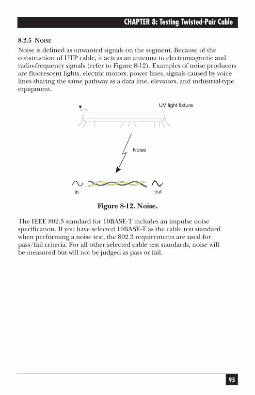
95
CHAPTER 8: Testing Twisted-Pair Cable
8.2.5 NOISE
Noise is defined as unwanted signals on the segment. Because of theconstruction of UTP cable, it acts as an antenna to electromagnetic andradio-frequency signals (refer to Figure 8-12). Examples of noise producersare fluorescent lights, electric motors, power lines, signals caused by voicelines sharing the same pathway as a data line, elevators, and industrial-typeequipment.
Figure 8-12. Noise.
The IEEE 802.3 standard for 10BASE-T includes an impulse noisespecification. If you have selected 10BASE-T as the cable test standardwhen performing a noise test, the 802.3 requirements are used forpass/fail criteria. For all other selected cable test standards, noise will be measured but will not be judged as pass or fail.
outin
UV light fixture
Noise
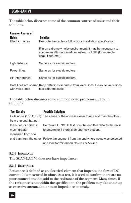
96
SCAN-LAN VI
The table below discusses some of the common sources of noise and theirsolutions.
Common Causes ofNoise SolutionElectric motors Re-route the cable or follow your installation specification.
If in an extremely noisy environment, it may be necessary to choose an alternate medium instead of UTP (for example, coax, fiber, etc.).
Light fixtures Same as for electric motors.
Power lines Same as for electric motors.
RF interference Same as for electric motors.
Data lines are shared Keep data lines separate from voice lines. Re-route voice lines with voice lines to a different cable.
The table below discusses some common noise problems and theirsolutions.
Test Results Possible SolutionsFails noise (10BASE-T) The cause of the noise is closer to one end than the other.
from one end, but not
the other, or noise is Perform a LENGTH test from the end that detects the noise
much greater to determine if there is an anomaly present.
measured from one
end than from the other Follow the segment from the end where noise was detected
and look for “Common Causes of Noise.”
8.2.6 IMPEDANCE
The SCAN-LAN VI does not have impedance.
8.2.7 RESISTANCE
Resistance is defined as an electrical element that impedes the flow of DCcurrent. It is measured in ohms. As a test, it is used to confirm there are nopoor connections that add to the resistance of the segment. Many times, ifthe resistance is not within the specification, the problem may also show upas excessive attenuation or as an impedance anomaly.
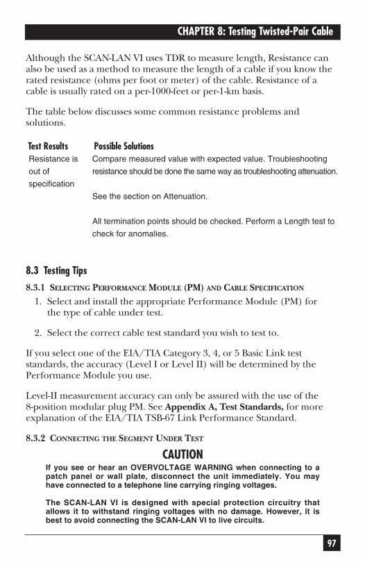
97
CHAPTER 8: Testing Twisted-Pair Cable
Although the SCAN-LAN VI uses TDR to measure length, Resistance canalso be used as a method to measure the length of a cable if you know therated resistance (ohms per foot or meter) of the cable. Resistance of acable is usually rated on a per-1000-feet or per-1-km basis.
The table below discusses some common resistance problems andsolutions.
Test Results Possible SolutionsResistance is Compare measured value with expected value. Troubleshooting
out of resistance should be done the same way as troubleshooting attenuation.
specification
See the section on Attenuation.
All termination points should be checked. Perform a Length test to
check for anomalies.
8.3 Testing Tips
8.3.1 SELECTING PERFORMANCE MODULE (PM) AND CABLE SPECIFICATION
1. Select and install the appropriate Performance Module (PM) for the type of cable under test.
2. Select the correct cable test standard you wish to test to.
If you select one of the EIA/TIA Category 3, 4, or 5 Basic Link teststandards, the accuracy (Level I or Level II) will be determined by thePerformance Module you use.
Level-II measurement accuracy can only be assured with the use of the8-position modular plug PM. See Appendix A, Test Standards, for moreexplanation of the EIA/TIA TSB-67 Link Performance Standard.
8.3.2 CONNECTING THE SEGMENT UNDER TEST
CAUTIONIf you see or hear an OVERVOLTAGE WARNING when connecting to apatch panel or wall plate, disconnect the unit immediately. You mayhave connected to a telephone line carrying ringing voltages.
The SCAN-LAN VI is designed with special protection circuitry thatallows it to withstand ringing voltages with no damage. However, it isbest to avoid connecting the SCAN-LAN VI to live circuits.
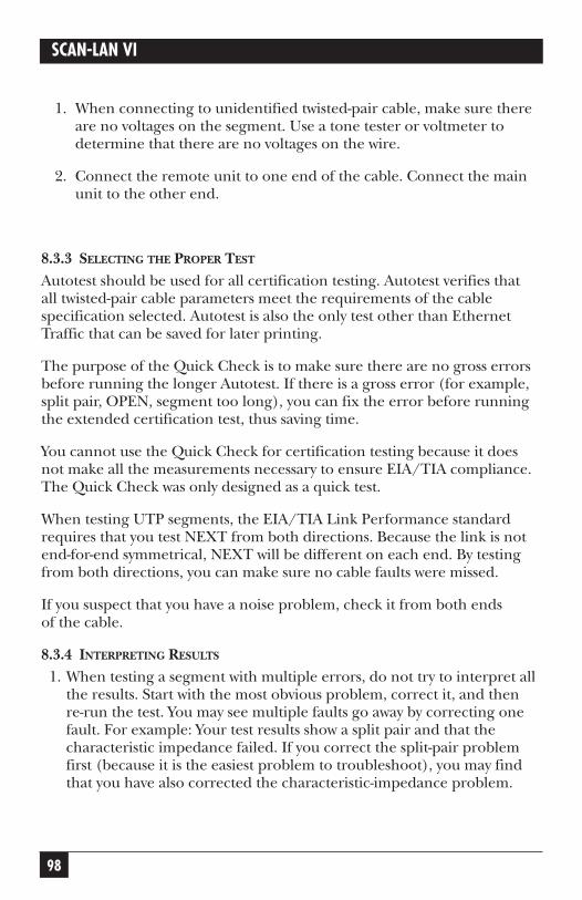
98
SCAN-LAN VI
1. When connecting to unidentified twisted-pair cable, make sure thereare no voltages on the segment. Use a tone tester or voltmeter todetermine that there are no voltages on the wire.
2. Connect the remote unit to one end of the cable. Connect the mainunit to the other end.
8.3.3 SELECTING THE PROPER TEST
Autotest should be used for all certification testing. Autotest verifies that all twisted-pair cable parameters meet the requirements of the cablespecification selected. Autotest is also the only test other than EthernetTraffic that can be saved for later printing.
The purpose of the Quick Check is to make sure there are no gross errorsbefore running the longer Autotest. If there is a gross error (for example,split pair, OPEN, segment too long), you can fix the error before runningthe extended certification test, thus saving time.
You cannot use the Quick Check for certification testing because it doesnot make all the measurements necessary to ensure EIA/TIA compliance.The Quick Check was only designed as a quick test.
When testing UTP segments, the EIA/TIA Link Performance standardrequires that you test NEXT from both directions. Because the link is notend-for-end symmetrical, NEXT will be different on each end. By testingfrom both directions, you can make sure no cable faults were missed.
If you suspect that you have a noise problem, check it from both ends of the cable.
8.3.4 INTERPRETING RESULTS
1. When testing a segment with multiple errors, do not try to interpret allthe results. Start with the most obvious problem, correct it, and then re-run the test. You may see multiple faults go away by correcting onefault. For example: Your test results show a split pair and that thecharacteristic impedance failed. If you correct the split-pair problemfirst (because it is the easiest problem to troubleshoot), you may findthat you have also corrected the characteristic-impedance problem.
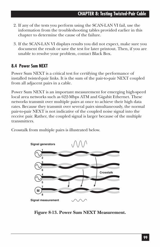
99
CHAPTER 8: Testing Twisted-Pair Cable
2. If any of the tests you perform using the SCAN-LAN VI fail, use theinformation from the troubleshooting tables provided earlier in thischapter to determine the cause of the failure.
3. If the SCAN-LAN VI displays results you did not expect, make sure youdocument the result or save the test for later printout. Then, if you areunable to resolve your problem, contact Black Box.
8.4 Power Sum NEXT
Power Sum NEXT is a critical test for certifying the performance ofinstalled twisted-pair links. It is the sum of the pair-to-pair NEXT coupledfrom all adjacent pairs in a cable.
Power Sum NEXT is an important measurement for emerging high-speedlocal area networks such as 622-Mbps ATM and Gigabit Ethernet. Thesenetworks transmit over multiple pairs at once to achieve their high datarates. Because they transmit over several pairs simultaneously, the normalpair-to-pair NEXT is not indicative of the coupled noise signal into thereceive pair. Rather, the coupled signal is larger because of the multipletransmitters.
Crosstalk from multiple pairs is illustrated below.
Figure 8-13. Power Sum NEXT Measurement.
M
Signal measurement
Signal generators
7
8
4
5
3
6
1
2
Crosstalk
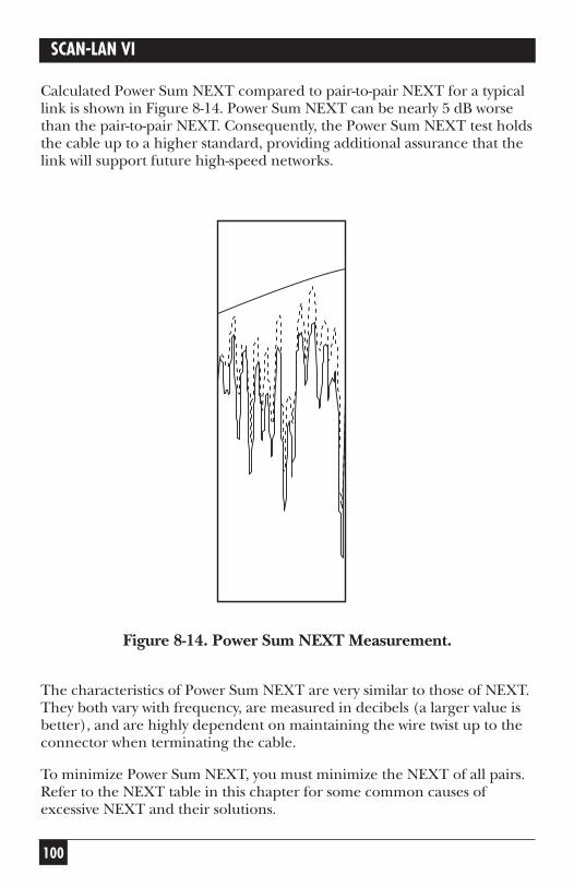
100
SCAN-LAN VI
Calculated Power Sum NEXT compared to pair-to-pair NEXT for a typicallink is shown in Figure 8-14. Power Sum NEXT can be nearly 5 dB worsethan the pair-to-pair NEXT. Consequently, the Power Sum NEXT test holdsthe cable up to a higher standard, providing additional assurance that thelink will support future high-speed networks.
Figure 8-14. Power Sum NEXT Measurement.
The characteristics of Power Sum NEXT are very similar to those of NEXT.They both vary with frequency, are measured in decibels (a larger value isbetter), and are highly dependent on maintaining the wire twist up to theconnector when terminating the cable.
To minimize Power Sum NEXT, you must minimize the NEXT of all pairs.Refer to the NEXT table in this chapter for some common causes ofexcessive NEXT and their solutions.
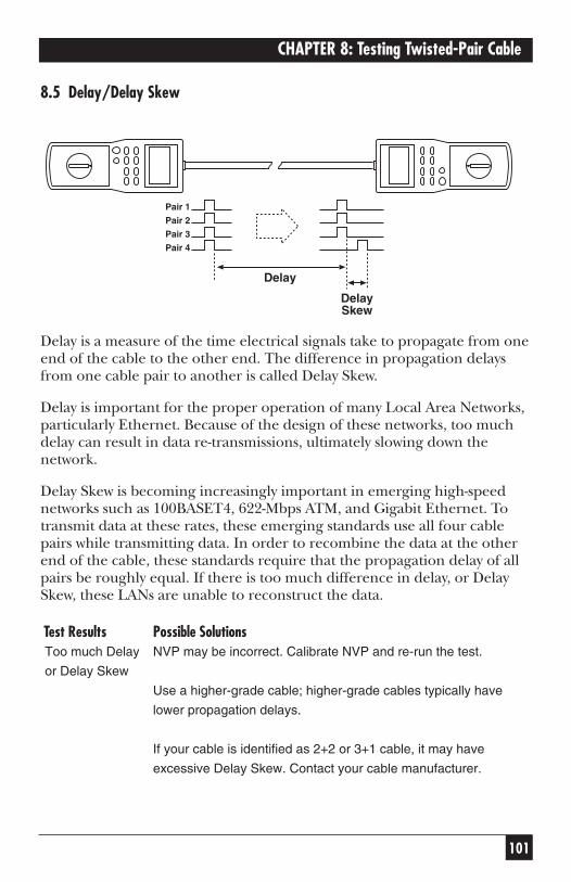
101
CHAPTER 8: Testing Twisted-Pair Cable
8.5 Delay/Delay Skew
Delay is a measure of the time electrical signals take to propagate from oneend of the cable to the other end. The difference in propagation delaysfrom one cable pair to another is called Delay Skew.
Delay is important for the proper operation of many Local Area Networks,particularly Ethernet. Because of the design of these networks, too muchdelay can result in data re-transmissions, ultimately slowing down thenetwork.
Delay Skew is becoming increasingly important in emerging high-speednetworks such as 100BASET4, 622-Mbps ATM, and Gigabit Ethernet. Totransmit data at these rates, these emerging standards use all four cablepairs while transmitting data. In order to recombine the data at the otherend of the cable, these standards require that the propagation delay of allpairs be roughly equal. If there is too much difference in delay, or DelaySkew, these LANs are unable to reconstruct the data.
Test Results Possible SolutionsToo much Delay NVP may be incorrect. Calibrate NVP and re-run the test.
or Delay Skew
Use a higher-grade cable; higher-grade cables typically have
lower propagation delays.
If your cable is identified as 2+2 or 3+1 cable, it may have
excessive Delay Skew. Contact your cable manufacturer.
Pair 1
Pair 2
Pair 3
Pair 4
Delay
DelaySkew

102
SCAN-LAN VI
9. Setup
9.1 Setup Functions
The following table provides information about the functions availableunder the SETUP dial position. The table details the softkey operations,the selections available for each setup parameter, and factory-set defaultvalues.
Table 9-1. Setup FunctionsFunction Softkey Operations Available Selections
(Default is bold)Units Feet, Meters Feet or Meters
Fault Thresh Default, Dec, Inc 4 to 10% (7%)
Noise Thresh Default, Dec, Inc 100 to 500 mV (260 mV)
PowerDown Dec, Inc 2 to 30 min. or disabled (5 min.)
BackLight Dec, Inc 15 seconds to 10 min. (1 min.)
Power Frequency 50 or 60 Hz 50 Hz, 60 Hz
Baud Rate Dec, Inc 1200 to 38,400 baud (9600 baud)
Flow Control None, XON/XOFF, Hardware None, XON/XOFF, Hardware
Date Format, Month, Day, Year mm/dd/yy
dd/mm/yy
yy/mm/dd
Time Hour, Minute, hh:mm:ss
Zero Seconds (24-hour mode only)
Audible Tone On, Off On or off
TRAF/NOISE On, Off On, Off
Tones
Company name MODIFY Co.
Left, Right, A-Z, a-z, 0-9, - , . / ( ) + * & #
Previous, Next Blank
Circuit Names Blank, None, Same, NEXT Blank, None, Same, NEXT
Auto Toner ON, OFF On, OFF
Reset to defaults Setup, NVPs Setup, NVP
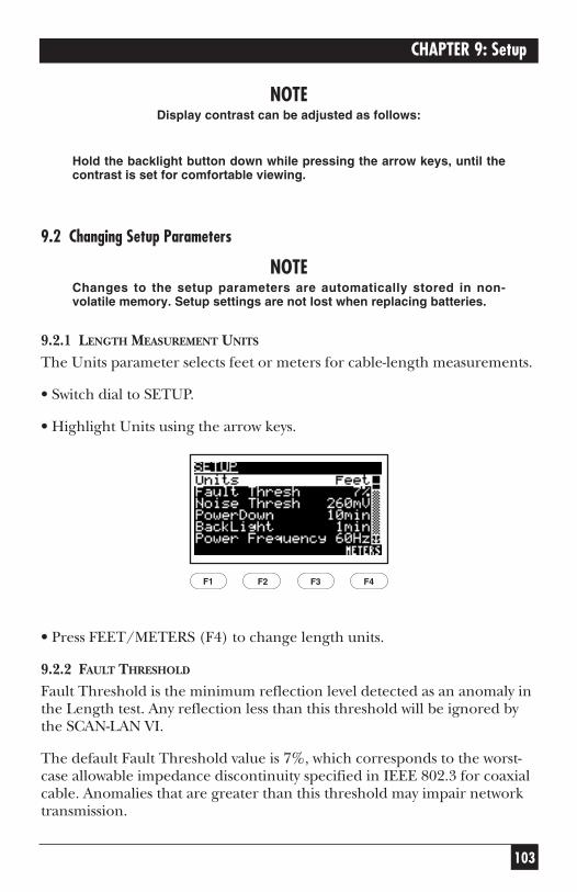
103
CHAPTER 9: Setup
NOTEDisplay contrast can be adjusted as follows:
Hold the backlight button down while pressing the arrow keys, until thecontrast is set for comfortable viewing.
9.2 Changing Setup Parameters
NOTEChanges to the setup parameters are automatically stored in non-volatile memory. Setup settings are not lost when replacing batteries.
9.2.1 LENGTH MEASUREMENT UNITS
The Units parameter selects feet or meters for cable-length measurements.
• Switch dial to SETUP.
• Highlight Units using the arrow keys.
• Press FEET/METERS (F4) to change length units.
9.2.2 FAULT THRESHOLD
Fault Threshold is the minimum reflection level detected as an anomaly inthe Length test. Any reflection less than this threshold will be ignored bythe SCAN-LAN VI.
The default Fault Threshold value is 7%, which corresponds to the worst-case allowable impedance discontinuity specified in IEEE 802.3 for coaxialcable. Anomalies that are greater than this threshold may impair networktransmission.
F1 F2 F3 F4
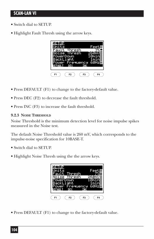
104
SCAN-LAN VI
• Switch dial to SETUP.
• Highlight Fault Thresh using the arrow keys.
• Press DEFAULT (F1) to change to the factory-default value.
• Press DEC (F2) to decrease the fault threshold.
• Press INC (F3) to increase the fault threshold.
9.2.3 NOISE THRESHOLD
Noise Threshold is the minimum detection level for noise impulse spikesmeasured in the Noise test.
The default Noise Threshold value is 260 mV, which corresponds to theimpulse-noise specification for 10BASE-T.
• Switch dial to SETUP.
• Highlight Noise Thresh using the the arrow keys.
• Press DEFAULT (F1) to change to the factory-default value.
F1 F2 F3 F4
F1 F2 F3 F4
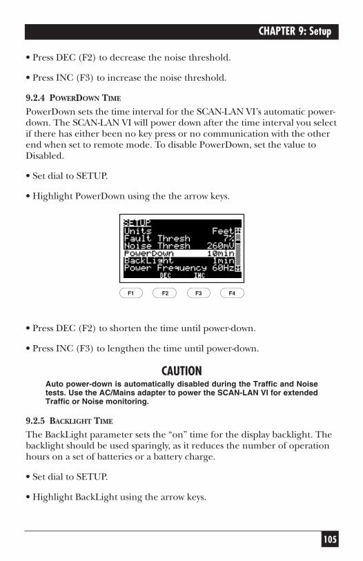
105
CHAPTER 9: Setup
• Press DEC (F2) to decrease the noise threshold.
• Press INC (F3) to increase the noise threshold.
9.2.4 POWERDOWN TIME
PowerDown sets the time interval for the SCAN-LAN VI’s automatic power-down. The SCAN-LAN VI will power down after the time interval you selectif there has either been no key press or no communication with the otherend when set to remote mode. To disable PowerDown, set the value toDisabled.
• Set dial to SETUP.
• Highlight PowerDown using the the arrow keys.
• Press DEC (F2) to shorten the time until power-down.
• Press INC (F3) to lengthen the time until power-down.
CAUTIONAuto power-down is automatically disabled during the Traffic and Noisetests. Use the AC/Mains adapter to power the SCAN-LAN VI for extendedTraffic or Noise monitoring.
9.2.5 BACKLIGHT TIME
The BackLight parameter sets the “on” time for the display backlight. Thebacklight should be used sparingly, as it reduces the number of operationhours on a set of batteries or a battery charge.
• Set dial to SETUP.
• Highlight BackLight using the arrow keys.
F1 F2 F3 F4
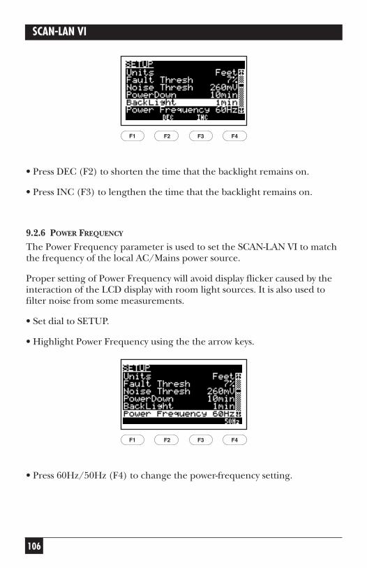
106
SCAN-LAN VI
• Press DEC (F2) to shorten the time that the backlight remains on.
• Press INC (F3) to lengthen the time that the backlight remains on.
9.2.6 POWER FREQUENCY
The Power Frequency parameter is used to set the SCAN-LAN VI to matchthe frequency of the local AC/Mains power source.
Proper setting of Power Frequency will avoid display flicker caused by theinteraction of the LCD display with room light sources. It is also used tofilter noise from some measurements.
• Set dial to SETUP.
• Highlight Power Frequency using the the arrow keys.
• Press 60Hz/50Hz (F4) to change the power-frequency setting.
F1 F2 F3 F4
F1 F2 F3 F4
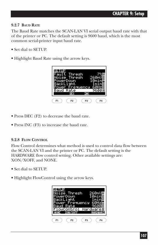
107
CHAPTER 9: Setup
9.2.7 BAUD RATE
The Baud Rate matches the SCAN-LAN VI serial output baud rate with thatof the printer or PC. The default setting is 9600 baud, which is the mostcommon serial-printer input baud rate.
• Set dial to SETUP.
• Highlight Baud Rate using the arrow keys.
• Press DEC (F2) to decrease the baud rate.
• Press INC (F3) to increase the baud rate.
9.2.8 FLOW CONTROL
Flow Control determines what method is used to control data flow betweenthe SCAN-LAN VI and the printer or PC. The default setting is theHARDWARE flow control setting. Other available settings are:XON/XOFF, and NONE.
• Set dial to SETUP.
• Highlight FlowControl using the arrow keys.
F1 F2 F3 F4
F1 F2 F3 F4
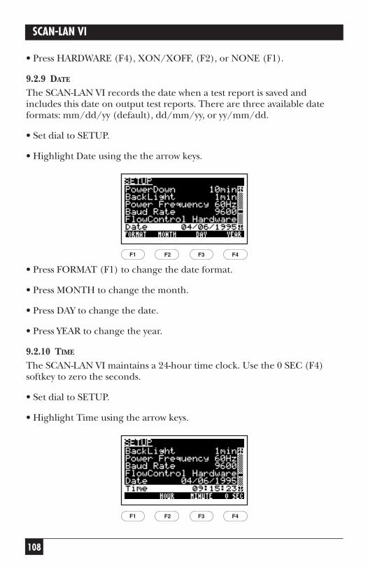
108
SCAN-LAN VI
• Press HARDWARE (F4), XON/XOFF, (F2), or NONE (F1).
9.2.9 DATE
The SCAN-LAN VI records the date when a test report is saved andincludes this date on output test reports. There are three available dateformats: mm/dd/yy (default), dd/mm/yy, or yy/mm/dd.
• Set dial to SETUP.
• Highlight Date using the the arrow keys.
• Press FORMAT (F1) to change the date format.
• Press MONTH to change the month.
• Press DAY to change the date.
• Press YEAR to change the year.
9.2.10 TIME
The SCAN-LAN VI maintains a 24-hour time clock. Use the 0 SEC (F4)softkey to zero the seconds.
• Set dial to SETUP.
• Highlight Time using the arrow keys.
F1 F2 F3 F4
F1 F2 F3 F4
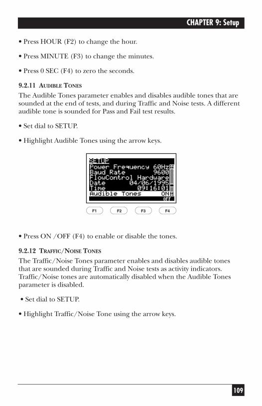
109
CHAPTER 9: Setup
• Press HOUR (F2) to change the hour.
• Press MINUTE (F3) to change the minutes.
• Press 0 SEC (F4) to zero the seconds.
9.2.11 AUDIBLE TONES
The Audible Tones parameter enables and disables audible tones that aresounded at the end of tests, and during Traffic and Noise tests. A differentaudible tone is sounded for Pass and Fail test results.
• Set dial to SETUP.
• Highlight Audible Tones using the arrow keys.
• Press ON /OFF (F4) to enable or disable the tones.
9.2.12 TRAFFIC/NOISE TONES
The Traffic/Noise Tones parameter enables and disables audible tones that are sounded during Traffic and Noise tests as activity indicators.Traffic/Noise tones are automatically disabled when the Audible Tonesparameter is disabled.
• Set dial to SETUP.
• Highlight Traffic/Noise Tone using the arrow keys.
F1 F2 F3 F4
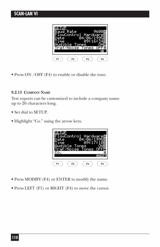
110
SCAN-LAN VI
• Press ON /OFF (F4) to enable or disable the tone.
9.2.13 COMPANY NAME
Test reports can be customized to include a company name up to 20 characters long.
• Set dial to SETUP.
• Highlight “Co.” using the arrow keys.
• Press MODIFY (F4) or ENTER to modify the name.
• Press LEFT (F1) or RIGHT (F4) to move the cursor.
F1 F2 F3 F4
F1 F2 F3 F4
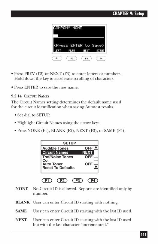
111
CHAPTER 9: Setup
• Press PREV (F2) or NEXT (F3) to enter letters or numbers.Hold down the key to accelerate scrolling of characters.
• Press ENTER to save the new name.
9.2.14 CIRCUIT NAMES
The Circuit Names setting determines the default name used for the circuit identification when saving Autotest results.
• Set dial to SETUP.
• Highlight Circuit Names using the arrow keys.
• Press NONE (F1), BLANK (F2), NEXT (F3), or SAME (F4).
NONE No Circuit ID is allowed. Reports are identified only bynumber.
BLANK User can enter Circuit ID starting with nothing.
SAME User can enter Circuit ID starting with the last ID used.
NEXT User can enter Circuit ID starting with the last ID used but with the last character “incremented.”
SETUP
Circuit NamesAudible Tones
Traf/Noise TonesCo.Auto Toner
F1 F2 F3 F4
NEXTOFF
OFF
OFFReset To Defaults
F1 F2 F3 F4
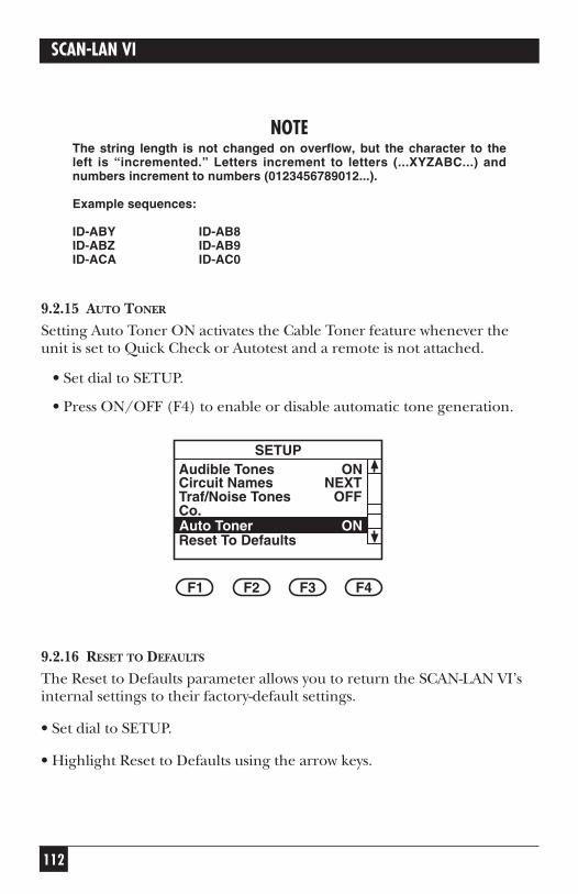
112
SCAN-LAN VI
NOTEThe string length is not changed on overflow, but the character to theleft is “incremented.” Letters increment to letters (...XYZABC...) andnumbers increment to numbers (0123456789012...).
Example sequences:
ID-ABY ID-AB8ID-ABZ ID-AB9ID-ACA ID-AC0
9.2.15 AUTO TONER
Setting Auto Toner ON activates the Cable Toner feature whenever theunit is set to Quick Check or Autotest and a remote is not attached.
• Set dial to SETUP.
• Press ON/OFF (F4) to enable or disable automatic tone generation.
9.2.16 RESET TO DEFAULTS
The Reset to Defaults parameter allows you to return the SCAN-LAN VI’sinternal settings to their factory-default settings.
• Set dial to SETUP.
• Highlight Reset to Defaults using the arrow keys.
SETUPAudible Tones
Traf/Noise TonesCo.
Circuit Names
F1 F2 F3 F4
ONNEXT
Reset To DefaultsAuto Toner ON
OFF
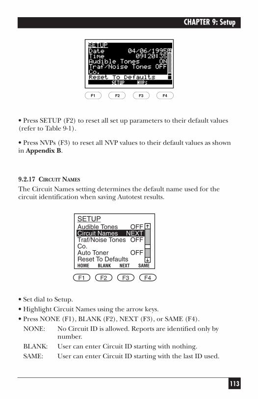
113
CHAPTER 9: Setup
• Press SETUP (F2) to reset all set up parameters to their default values(refer to Table 9-1).
• Press NVPs (F3) to reset all NVP values to their default values as shown in Appendix B.
9.2.17 CIRCUIT NAMES
The Circuit Names setting determines the default name used for thecircuit identification when saving Autotest results.
• Set dial to Setup.• Highlight Circuit Names using the arrow keys.• Press NONE (F1), BLANK (F2), NEXT (F3), or SAME (F4).
NONE: No Circuit ID is allowed. Reports are identified only bynumber.
BLANK: User can enter Circuit ID starting with nothing.SAME: User can enter Circuit ID starting with the last ID used.
Audible TonesCircuit NamesTraf/Noise TonesCo.Auto TonerReset To Defaults
OFFNEXT
OFF
OFF
HOME BLANK NEXT SAME
SETUP
F1 F2 F3 F4
F1 F2 F3 F4
114
SCAN-LAN VI
NEXT: User can enter Circuit ID starting with the last ID used butwith the last character “incremented.”
NOTEThe string length is not changed on overflow but the character to the leftis “incremented.” Letters increment to letters (...XYZABC...) andnumbers increment to numbers (0123456789012...).
Example sequences:
ID-ABYID-ABZID-ACA
ID-AB8ID-AB9ID-AC0
115
CHAPTER 10: Calibration
10. CalibrationThe SCAN-LAN VI performs four types of calibration: NVP calibration,remote-unit calibration, performance-module calibration, impedancecalibration, resistance calibration, and main-unit calibration.
10.1 NVP Calibration
A default Nominal Velocity of Propagation (NVP) value is preselected inthe SCAN-LAN VI depending on the cable test standard selected. Moreprecise NVP values can be set using one of the following procedures. NVPcalibration using a section of the actual cable to be tested is the moreaccurate of the two procedures.
10.1.1 USING A KNOWN LENGTH OF CABLE
To measure and save the NVP of a known length of cable, perform thefollowing steps.
1. Set dial to CAL.
2. Select NVP from the calibration menu and press CAL (F4) or ENTER.
(Press arrow keys to change the cable test standard and press SAVE(F4) or ENTER.)
3. Connect a known length of sample cable to the SCAN-LAN VI. Thecable must be at least 50 feet (15.2 meters) long to get an accuratemeasurement (longer lengths improve accuracy). Leave the far end of the cable open.
4. Press START (F1).
5. Press DEC (F2) or INC (F3) to adjust the cable length on the display to the known cable length.
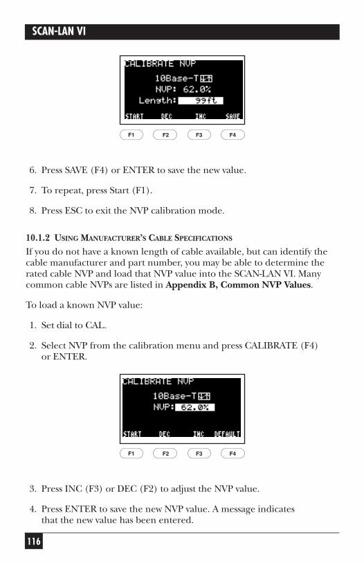
116
SCAN-LAN VI
6. Press SAVE (F4) or ENTER to save the new value.
7. To repeat, press Start (F1).
8. Press ESC to exit the NVP calibration mode.
10.1.2 USING MANUFACTURER’S CABLE SPECIFICATIONS
If you do not have a known length of cable available, but can identify thecable manufacturer and part number, you may be able to determine therated cable NVP and load that NVP value into the SCAN-LAN VI. Manycommon cable NVPs are listed in Appendix B, Common NVP Values.
To load a known NVP value:
1. Set dial to CAL.
2. Select NVP from the calibration menu and press CALIBRATE (F4) or ENTER.
3. Press INC (F3) or DEC (F2) to adjust the NVP value.
4. Press ENTER to save the new NVP value. A message indicates that the new value has been entered.
F1 F2 F3 F4
F1 F2 F3 F4
117
CHAPTER 10: Calibration
5. Press ESC to exit the NVP calibration mode.
10.1.3 WHY DO I NEED TO SET CABLE NVP?In order to make accurate cable-length measurements, the correct cableNominal Velocity of Propagation (NVP) value must be set in the SCAN-LAN VI. The NVP is a measure of how fast an electrical pulse travels downa cable compared to the speed of light.
NVP is expressed as a percentage, usually between 50 and 90%. A defaultNVP value is automatically set by the SCAN-LAN VI based upon the cabletest standard selected.
Using the default value, however, may result in cable-length measurementerrors of up to 7%, due to the variation in the signal propagation rate from cable to cable. This potential length error usually will not impairtroubleshooting of a cable segment that used to work unless the lengthmeasurement of a cable is close to the test limit (for example 100 meterson a 10BASE-T segment).
When using the SCAN-LAN VI for cable certification, determine the truecable NVP and save the value. This will give you the most accurate cable-length measurements and will avoid failing cable segments that are close to the test limit.
10.2 Remote-Unit Calibration
Remote-unit calibration should be performed on a periodic basis in orderto maintain the accuracy of attenuation measurements. Remote calibrationis most sensitive to temperature changes. Allow both main and remoteunits to stabilize to their operating environment before performing thecalibration procedure.
Each SCAN-LAN VI is calibrated for remote operation at the factory. It’snot necessary to re-calibrate the Remote unless a new SCAN-LAN VI is usedfor remote operation. However, if Remote Calibration is performed, it’simportant to verify that the calibration was completed properly.
To calibrate the remote unit:
1. Connect the main unit to the CAT 3 calibration coupler, using theModular Plug Performance Module. (If you are using the Modular JackPerformance Module, use the four-foot CAT 5 patch cord.)
118
SCAN-LAN VI
2. Connect the remote unit to the open end of the CAT 3 calibrationcoupler using the Modular Plug Performance Module.
3. Set the remote unit’s dial to REMOTE.
4. Set the main unit’s dial to CAL.
5. Highlight REMOTE in the Calibrate menu.
6. When the test is finished, the screen returns to the Calibrate menu.
NOTEIn order to ensure correct calibration, be sure to switch the roles of bothunits, and repeat the procedure above.
To verify the calibration:
1. Connect the main unit to the CAT 3 calibration coupler, using theModular Plug Performance Module.
2. Connect the remote unit to the open end of the CAT 3 calibrationcoupler using the Modular Plug Performance Module.
3. Turn the knob to Quick √. Press the up or down arrow key to select theCAT 5 Basic Link test standard. Press ENTER or SAVE (F4) to start thetest.
4. Once the test is complete, press VIEW (F3). Press the up or downarrow key until the Attenuation results are displayed. The Attenuationresults should display values greater than 0.0 dB. If 0.0 dB is displayedfor any or all pairs, perform the Remote Calibration again. If theproblem continues, contact Black Box.
10.3 Performance-Module Calibration
Each Performance Module used with the SCAN-LAN VI needs to becalibrated in order to deliver maximum measurement accuracy. SCAN-LAN VI automatically recognizes which type of Performance Module isinstalled. It is possible for the SCAN-LAN VI to be calibrated to a numberof Performance Modules at the same time, provided that they are differenttypes. For example, the SCAN-LAN VI can be calibrated to both a ModularPlug Module and a Modular Jack Module, thus allowing change from onePerformance Module to the other without need for recalibration. If a
119
CHAPTER 10: Calibration
Performance Module is replaced with another of the same type, however,calibration of the new Performance Module should be performed.
A Calibration Standard is available for convenient field calibration oftwisted-pair Performance Modules. This Standard also enables you at anytime to perform a “confidence check” on the proper operation of aPerformance Module by repeating the calibration procedure.
To calibrate a Performance Module:
NOTEPress ESC at any time to cancel the calibration procedure.
1. Set dial to CAL.
2. Highlight PERFORMANCE MODULE in the Calibrate menu using thearrow keys.
3. Press CALIBRATE (F4) or ENTER. The CALIBRATE PERFORMANCEMODULE screen will appear with the displayed message “Connect ToJACK 1.”
4. Connect the SCAN-LAN VI to JACK 1 of the Calibration Standard.(Use a Category 5 Patch Cord for connecting a Modular JackPerformance Module to the Calibration Standard.)
5. Press START (F4) or ENTER. The message “CALIBRATING...” will bedisplayed on the screen. The bar graph across the bottom of the displaywill show the progress of the calibration. Press CANCEL (F1) or ESC tocancel the calibration procedure.
6. After approximately 45 seconds, the SCAN-LAN VI will display themessage “Connect To JACK 2.” Remove the plug from JACK 1 andinsert it into JACK 2.
7. Press CONTINUE (F4) or ENTER. The message “CALIBRATING...”will be displayed, and the bar graph across the bottom of the displaywill show the progress of the calibration. Press CANCEL (F1) or ESC to cancel the calibration procedure.
8. After approximately 45 seconds, the SCAN-LAN VI will display themessage “Connect To JACK 3.” Remove the plug from JACK 2 andinsert it into JACK 3.
120
SCAN-LAN VI
9. Press CONTINUE (F4) or ENTER. The message “CALIBRATING...”will be displayed, and the bar graph across the bottom of the displaywill show the progress of the calibration. Press CANCEL (F1) or ESC to cancel the calibration procedure. When finished, the screen returnsto the CALIBRATE menu.
NOTEIf at any time during the above procedure an error message is displayedon the screen, start at the beginning of the instructions and attempt thecalibration again. If the problem continues, contact Black Box fortechnical support.
10.4 Impedance Calibration
The SCAN-LAN VI does not support impedance calibration.
10.5 Resistance Calibration
Resistance calibration should be performed on a periodic basis in order to maintain maximum accuracy. Resistance calibration is most sensitive to temperature changes. Allow the main unit to stabilize to the operatingenvironment before performing the calibration procedure. Calibrationshould be performed whenever a different Performance Module isinstalled.
To calibrate Resistance:
1. Connect the SCAN-LAN VI to the Remote Unit.
2. Set the dial to CAL.
3. Highlight Resistance in the Calibrate menu by using the arrow keys.
4. Press CALIBRATE (F4) or ENTER. The Calibrate Resistance screenwill appear. The bar graph across the bottom of the display will showthe progress of the calibration.
5. When finished, the screen returns to the CALIBRATE menu.
10.6 Main-Unit Calibration
This calibration mode is intended for factory use only.
121
CHAPTER 11: Ethernet Traffic Analysis
11. Ethernet Traffic AnalysisTraffic provides a report of Ethernet network utilization and activity.
The SCAN-LAN VI monitors live traffic on 10BASE-T Ethernet networksand continuously displays the percentage of network utilization, peaktraffic, and collisions on the screen along with a bar-graph display ofnetwork activity. An audio tone provides feedback of network activity.
Test results are saved in the SCAN-LAN VI’s memory and can be printedwhen the test is completed. The printout includes a graph of networkactivity over time showing average utilization, peak utilization, percentage of collisions, packet counts, and jabber conditions. For 10BASE-T networks,the SCAN-LAN VI automatically generates link pulses to activate the huband reports whenever a link state with the hub is lost.
Because the Traffic test runs continuously, use the AC/Mains adapter if the test is to be run for an extended period.
The SCAN-LAN VI’s Traffic test reports: Network utilization percentage,peak traffic, and collisions.
The Traffic test also detects: Jabber, loss of link connections (10BASE-T),and wrong polarity.
11.1 Running the Traffic Test
1. Connect the SCAN-LAN VI directly to the network either at the10BASE-T hub or at the end of a cable segment.
2. Switch dial to TRAFFIC. (Press arrow keys to change the cable teststandard and SAVE (F4) or ENTER to select a cable test standard.)
3. Press ENTER to clear the last Traffic test from memory and start a newtest.
CAUTIONAuto power-down is disabled during the Traffic test. Use the AC/Mainsadapter to power the SCAN-LAN VI for extended Traffic monitoring.
122
SCAN-LAN VI
11.2 Viewing Traffic Results
The screen displays a continuous reading of traffic conditions on thenetwork.
FEATURE DESCRIPTIONOne Sec Traffic Shows the average network utilization over the last second.
Average traffic utilization over 30 to 40% indicates a heavily loaded network.
Peak Traffic The highest one-second average traffic over the duration of the test.
Collisions Shows the current collisions rate over the last second, expressed as a percentage of total packets transmitted. Collisions are counted when runt packets (shorter than a valid minimum packet length) are detected.
Collision rates exceeding 3% may indicate a faulty station or network interface card, or an excessively long cable segment.
Last Error Identifies detected transmission errors and the time since the last error ended in hours, minutes, and seconds.
Error Since Identifies detected transmission errors and the time the error started in hours, minutes, and seconds.
Bar Graph Displays the current traffic level, scaled from 0 on the left to 50% on the right side of the display.
Traffic test can detect the following three errors:
ERROR DESCRIPTIONNo Link Pulse Indicates that there were no Link pulses received from the
10BASE-T hub, possibly as a result of a faulty hub or cable link connected to the hub.
Wrong polarity Indicates possible miswire of cable link or hub port caused by tip/ring reversal on a wire pair.
Jabber Indicates illegal packet length of greater than 20 ms was
received. This suggests a faulty network interface card.
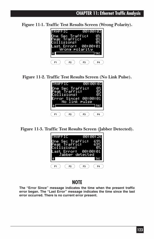
123
CHAPTER 11: Ethernet Traffic Analysis
Figure 11-1. Traffic Test Results Screen (Wrong Polarity).
Figure 11-2. Traffic Test Results Screen (No Link Pulse).
Figure 11-3. Traffic Test Results Screen (Jabber Detected).
NOTEThe “Error Since” message indicates the time when the present trafficerror began. The “Last Error” message indicates the time since the lasterror occurred. There is no current error present.
F1 F2 F3 F4
F1 F2 F3 F4
F1 F2 F3 F4
124
SCAN-LAN VI
12. Self-TestIf the SCAN-LAN VI fails to operate as expected, or exhibits inaccuratereadings, perform a self-test.
To run a self-test:
1. Set the dial to EXTENDED FUNCTIONS.
2. Press the arrow keys to highlight SELF-TEST.
3. Press ENTER. The test begins immediately and the screen displays thetest results.
If the self-test fails, make a note of which test fails and contact Black Box.
If the SCAN-LAN VI passes the self-test, but still does not perform properly,perform the calibration procedure (refer to Chapter 10, Calibration). Ifyou continue to experience problems, make a note of the circumstancesand print a cable report, if applicable. Then call Black Box.
You must obtain a Return Material Authorization (RMA) number beforesending the unit in for repair.
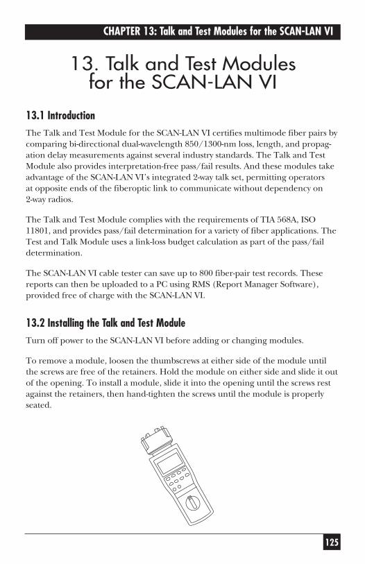
125
CHAPTER 13: Talk and Test Modules for the SCAN-LAN VI
13. Talk and Test Modules for the SCAN-LAN VI
13.1 IntroductionThe Talk and Test Module for the SCAN-LAN VI certifies multimode fiber pairs bycomparing bi-directional dual-wavelength 850/1300-nm loss, length, and propag-ation delay measurements against several industry standards. The Talk and TestModule also provides interpretation-free pass/fail results. And these modules takeadvantage of the SCAN-LAN VI’s integrated 2-way talk set, permitting operators at opposite ends of the fiberoptic link to communicate without dependency on 2-way radios.
The Talk and Test Module complies with the requirements of TIA 568A, ISO11801, and provides pass/fail determination for a variety of fiber applications. TheTest and Talk Module uses a link-loss budget calculation as part of the pass/faildetermination.
The SCAN-LAN VI cable tester can save up to 800 fiber-pair test records. Thesereports can then be uploaded to a PC using RMS (Report Manager Software),provided free of charge with the SCAN-LAN VI.
13.2 Installing the Talk and Test ModuleTurn off power to the SCAN-LAN VI before adding or changing modules.
To remove a module, loosen the thumbscrews at either side of the module untilthe screws are free of the retainers. Hold the module on either side and slide it outof the opening. To install a module, slide it into the opening until the screws restagainst the retainers, then hand-tighten the screws until the module is properlyseated.
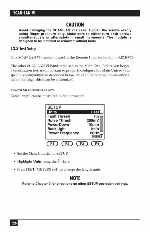
126
SCAN-LAN VI
CAUTIONAvoid damaging the SCAN-LAN VI’s case. Tighten the screws evenlyusing finger pressure only. Make sure to either turn both screwssimultaneously or alternately in small increments. The module isdesigned to be installed or removed without tools.
13.3 Test Setup
One SCAN-LAN VI handset is used as the Remote Unit. Set its dial to REMOTE.
The other SCAN-LAN VI handset is used as the Main Unit. Before you begin a certification test, it’s important to properly configure the Main Unit to yourspecific configuration as described below. All of the following options offer adefault setting, which can be customized.
LENGTH MEASUREMENTS UNITS
Cable length can be measured in feet or meters.
• Set the Main Unit dial to SETUP.
• Highlight Units using the ↑↓ keys.
• Press FEET/METERS (F4) to change the length units.
NOTERefer to Chapter 9 for directions on other SETUP operation settings.
SETUPUnits FeetFault Thresh 7%Noise Thresh 260mVPowerDown 10minBackLight 1minPower Frequency 60Hz
METERS
F1 F2 F3 F4
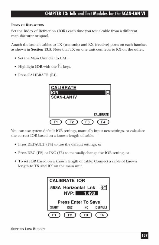
127
CHAPTER 13: Talk and Test Modules for the SCAN-LAN VI
INDEX OF REFRACTION
Set the Index of Refraction (IOR) each time you test a cable from a differentmanufacturer or spool.
Attach the launch cables to TX (transmit) and RX (receive) ports on each handsetas shown in Section 13.5. Note that TX on one unit connects to RX on the other.
• Set the Main Unit dial to CAL.
• Highlight IOR with the ↑↓ keys.
• Press CALIBRATE (F4).
You can use system-default IOR settings, manually input new settings, or calculatethe correct IOR based on a known length of cable.
• Press DEFAULT (F4) to use the default settings, or
• Press DEC (F2) or INC (F3) to manually change the IOR setting, or
• To set IOR based on a known length of cable: Connect a cable of knownlength to TX and RX on the main unit.
SETTING LOSS BUDGET
CALIBRATE IOR
DEFAULT
F1 F2 F3 F4
Press Enter To SaveINCDECSTART
568A Horizontal LnkNVP: 1.490
CALIBRATEIORSCAN-LAN IV
CALIBRATE
F1 F2 F3 F4
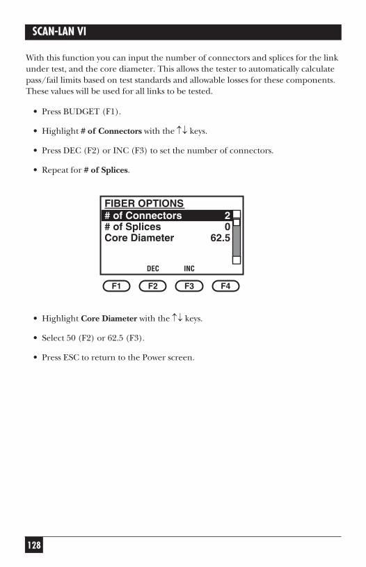
128
SCAN-LAN VI
With this function you can input the number of connectors and splices for the linkunder test, and the core diameter. This allows the tester to automatically calculatepass/fail limits based on test standards and allowable losses for these components.These values will be used for all links to be tested.
• Press BUDGET (F1).
• Highlight # of Connectors with the ↑↓ keys.
• Press DEC (F2) or INC (F3) to set the number of connectors.
• Repeat for # of Splices.
• Highlight Core Diameter with the ↑↓ keys.
• Select 50 (F2) or 62.5 (F3).
• Press ESC to return to the Power screen.
FIBER OPTIONS# of Connectors 2# of Splices 0Core Diameter 62.5
DEC
F1 F2 F3 F4
INC
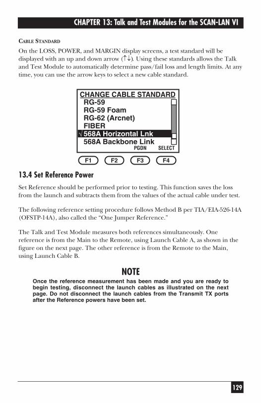
129
CHAPTER 13: Talk and Test Modules for the SCAN-LAN VI
CABLE STANDARD
On the LOSS, POWER, and MARGIN display screens, a test standard will bedisplayed with an up and down arrow (↑↓). Using these standards allows the Talkand Test Module to automatically determine pass/fail loss and length limits. At anytime, you can use the arrow keys to select a new cable standard.
13.4 Set Reference PowerSet Reference should be performed prior to testing. This function saves the lossfrom the launch and subtracts them from the values of the actual cable under test.
The following reference setting procedure follows Method B per TIA/EIA-526-14A(OFSTP-14A), also called the “One Jumper Reference.”
The Talk and Test Module measures both references simultaneously. Onereference is from the Main to the Remote, using Launch Cable A, as shown in thefigure on the next page. The other reference is from the Remote to the Main,using Launch Cable B.
NOTEOnce the reference measurement has been made and you are ready tobegin testing, disconnect the launch cables as illustrated on the nextpage. Do not disconnect the launch cables from the Transmit TX portsafter the Reference powers have been set.
CHANGE CABLE STANDARDRG-59RG-59 FoamRG-62 (Arcnet)FIBER568A Horizontal Lnk568A Backbone Link
SELECT
F1 F2 F3 F4
√
PGDN
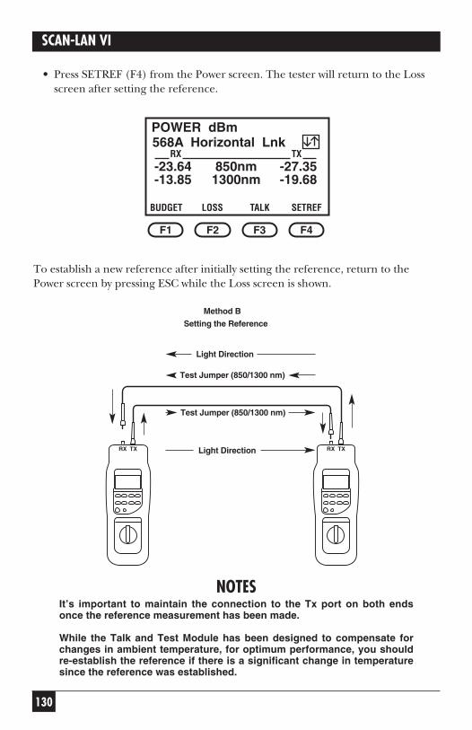
130
SCAN-LAN VI
• Press SETREF (F4) from the Power screen. The tester will return to the Lossscreen after setting the reference.
To establish a new reference after initially setting the reference, return to thePower screen by pressing ESC while the Loss screen is shown.
NOTESIt’s important to maintain the connection to the Tx port on both endsonce the reference measurement has been made.
While the Talk and Test Module has been designed to compensate forchanges in ambient temperature, for optimum performance, you shouldre-establish the reference if there is a significant change in temperaturesince the reference was established.
RX TX RX TX
POWER dBm
SETREF
F1 F2 F3 F4
-23.64 850nm -27.35-13.85 1300nm -19.68
TALKLOSSBUDGET
568A Horizontal LnkRX TX
Test Jumper (850/1300 nm)
Test Jumper (850/1300 nm)
Light Direction
Light Direction
Method B
Setting the Reference
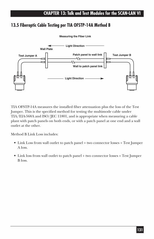
131
CHAPTER 13: Talk and Test Modules for the SCAN-LAN VI
13.5 Fiberoptic Cable Testing per TIA OFSTP-14A Method B
TIA OFSTP-14A measures the installed fiber attenuation plus the loss of the TestJumper. This is the specified method for testing the multimode cable underTIA/EIA-568A and ISO/JEC 11801, and is appropriate when measuring a cableplant with patch panels on both ends, or with a patch panel at one end and a walloutlet at the other.
Method B Link Loss includes:
• Link Loss from wall outlet to patch panel + two connector losses + Test JumperA loss.
• Link loss from wall outlet to patch panel + two connector losses + Test JumperB loss.
RX TX TXRX
Light Direction
Light Direction
Test Jumper A Test Jumper B
Wall to patch panel link
Patch panel to wall link
Wall Plate
Measuring the Fiber Link
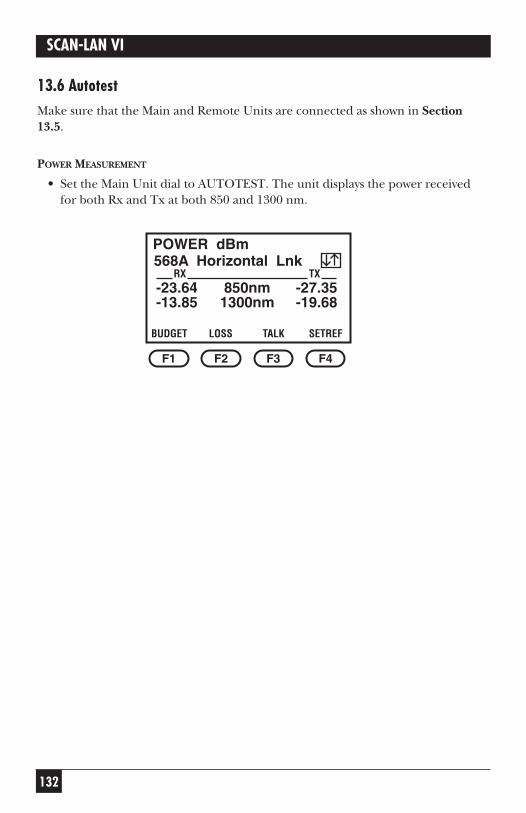
132
SCAN-LAN VI
13.6 AutotestMake sure that the Main and Remote Units are connected as shown in Section13.5.
POWER MEASUREMENT
• Set the Main Unit dial to AUTOTEST. The unit displays the power receivedfor both Rx and Tx at both 850 and 1300 nm.
POWER dBm
SETREF
F1 F2 F3 F4
-23.64 850nm -27.35-13.85 1300nm -19.68
TALKLOSSBUDGET
568A Horizontal LnkRX TX
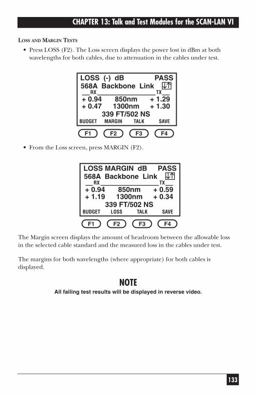
133
CHAPTER 13: Talk and Test Modules for the SCAN-LAN VI
LOSS AND MARGIN TESTS
• Press LOSS (F2). The Loss screen displays the power lost in dBm at bothwavelengths for both cables, due to attenuation in the cables under test.
• From the Loss screen, press MARGIN (F2).
The Margin screen displays the amount of headroom between the allowable loss in the selected cable standard and the measured loss in the cables under test.
The margins for both wavelengths (where appropriate) for both cables isdisplayed.
NOTEAll failing test results will be displayed in reverse video.
LOSS MARGIN dB
SAVE
F1 F2 F3 F4
+ 0.94 850nm + 0.59+ 1.19 1300nm + 0.34
TALKLOSSBUDGET
568A Backbone LinkRX TX
339 FT/502 NS
PASS
LOSS (-) dB
SAVE
F1 F2 F3 F4
+ 0.94 850nm + 1.29+ 0.47 1300nm + 1.30
TALKMARGINBUDGET
568A Backbone LinkRX TX
339 FT/502 NS
PASS
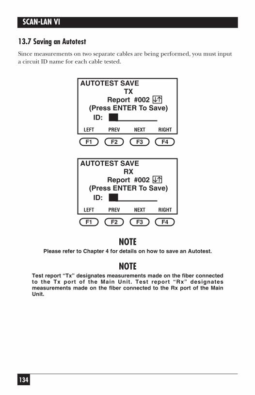
134
SCAN-LAN VI
13.7 Saving an AutotestSince measurements on two separate cables are being performed, you must input a circuit ID name for each cable tested.
NOTEPlease refer to Chapter 4 for details on how to save an Autotest.
NOTETest report “Tx” designates measurements made on the fiber connectedto the Tx port of the Main Unit. Test report “Rx” designatesmeasurements made on the fiber connected to the Rx port of the MainUnit.
AUTOTEST SAVE
RIGHT
F1 F2 F3 F4
(Press ENTER To Save)
NEXTPREVLEFT
Report #002
ID:
RX
AUTOTEST SAVE
RIGHT
F1 F2 F3 F4
(Press ENTER To Save)
NEXTPREVLEFT
Report #002
ID:
TX
135
CHAPTER 13: Talk and Test Modules for the SCAN-LAN VI
13.8 Printing, Uploading, and Viewing Test ResultsYou can view or print test results from the Main Unit, or upload the results to a PC for viewing or printing with Report Manager software.
13.9 LinkTalkLinkTalk allows two Talk and Test units to function as an audio communicationsystem. This feature provides half-duplex voice communication between the Mainand Remote Units. Refer to Section 4.5 for more information on LinkTalk.
136
SCAN-LAN VI
Appendix A: Test StandardsThe SCAN-LAN VI tests cabling to the performance required by the cabletest standard chosen. The test limits for each specification standard arelisted in the tables in this appendix.
SCAN-LAN VI cable test standards may be modified to add/remove cabletests (for example, cable resistance) and modify which pairs are tested.
A.1 Installed Link Test Configurations
Cabling-system performance requirements have been established by theindustry association EIA/TIA in Technical Systems Bulletin 67. TSB-67 alsodefines two installed cabling test configurations, the Channel and the BasicLink.
The primary difference between the Channel and the Basic Linkconfigurations is that the Channel includes the user’s patch cords andequipment cords used to connect to the workstation (at the office end)and to the communications distribution equipment/hub (at the wiringcloset). The Basic Link excludes the user’s patch cords and equipmentcords.
A.2 Channel Testing
You use the Channel configuration when the need arises to diagnosesystem problems in existing networks.
The figure on the next page illustrates a typical test setup using two SCAN-LAN VI to test a Channel.
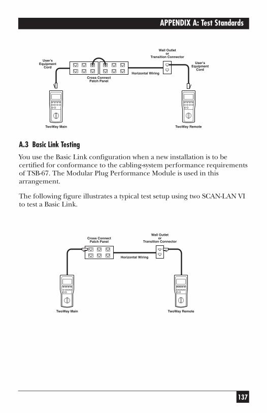
137
APPENDIX A: Test Standards
A.3 Basic Link Testing
You use the Basic Link configuration when a new installation is to becertified for conformance to the cabling-system performance requirementsof TSB-67. The Modular Plug Performance Module is used in thisarrangement.
The following figure illustrates a typical test setup using two SCAN-LAN VIto test a Basic Link.
TwoWay Remote
Horizontal Wiring
Cross ConnectPatch Panel
Wall Outletor
Transition Connector
TwoWay Main
TwoWay Remote
Horizontal WiringCross Connect
Patch Panel
Wall Outletor
Transition Connector
TwoWay Main
User'sEquipment
CordUser's
EquipmentCord
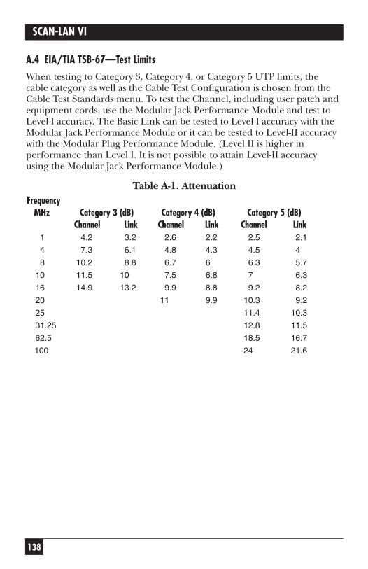
138
SCAN-LAN VI
A.4 EIA/TIA TSB-67—Test Limits
When testing to Category 3, Category 4, or Category 5 UTP limits, thecable category as well as the Cable Test Configuration is chosen from theCable Test Standards menu. To test the Channel, including user patch andequipment cords, use the Modular Jack Performance Module and test toLevel-I accuracy. The Basic Link can be tested to Level-I accuracy with theModular Jack Performance Module or it can be tested to Level-II accuracywith the Modular Plug Performance Module. (Level II is higher inperformance than Level I. It is not possible to attain Level-II accuracy using the Modular Jack Performance Module.)
Table A-1. AttenuationFrequency
MHz Category 3 (dB) Category 4 (dB) Category 5 (dB)Channel Link Channel Link Channel Link
1 4.2 3.2 2.6 2.2 2.5 2.1
4 7.3 6.1 4.8 4.3 4.5 4
8 10.2 8.8 6.7 6 6.3 5.7
10 11.5 10 7.5 6.8 7 6.3
16 14.9 13.2 9.9 8.8 9.2 8.2
20 11 9.9 10.3 9.2
25 11.4 10.3
31.25 12.8 11.5
62.5 18.5 16.7
100 24 21.6
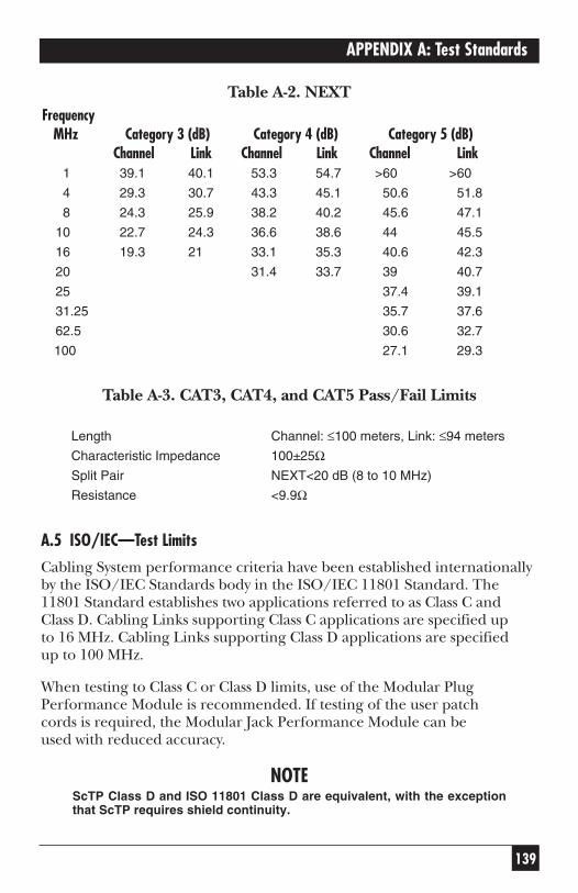
139
APPENDIX A: Test Standards
Table A-2. NEXTFrequency
MHz Category 3 (dB) Category 4 (dB) Category 5 (dB)Channel Link Channel Link Channel Link
1 39.1 40.1 53.3 54.7 >60 >60
4 29.3 30.7 43.3 45.1 50.6 51.8
8 24.3 25.9 38.2 40.2 45.6 47.1
10 22.7 24.3 36.6 38.6 44 45.5
16 19.3 21 33.1 35.3 40.6 42.3
20 31.4 33.7 39 40.7
25 37.4 39.1
31.25 35.7 37.6
62.5 30.6 32.7
100 27.1 29.3
Table A-3. CAT3, CAT4, and CAT5 Pass/Fail Limits
Length Channel: ≤100 meters, Link: ≤94 meters
Characteristic Impedance 100±25ΩSplit Pair NEXT<20 dB (8 to 10 MHz)
Resistance <9.9Ω
A.5 ISO/IEC—Test Limits
Cabling System performance criteria have been established internationallyby the ISO/IEC Standards body in the ISO/IEC 11801 Standard. The11801 Standard establishes two applications referred to as Class C and Class D. Cabling Links supporting Class C applications are specified upto 16 MHz. Cabling Links supporting Class D applications are specified up to 100 MHz.
When testing to Class C or Class D limits, use of the Modular PlugPerformance Module is recommended. If testing of the user patch cords is required, the Modular Jack Performance Module can be used with reduced accuracy.
NOTEScTP Class D and ISO 11801 Class D are equivalent, with the exceptionthat ScTP requires shield continuity.
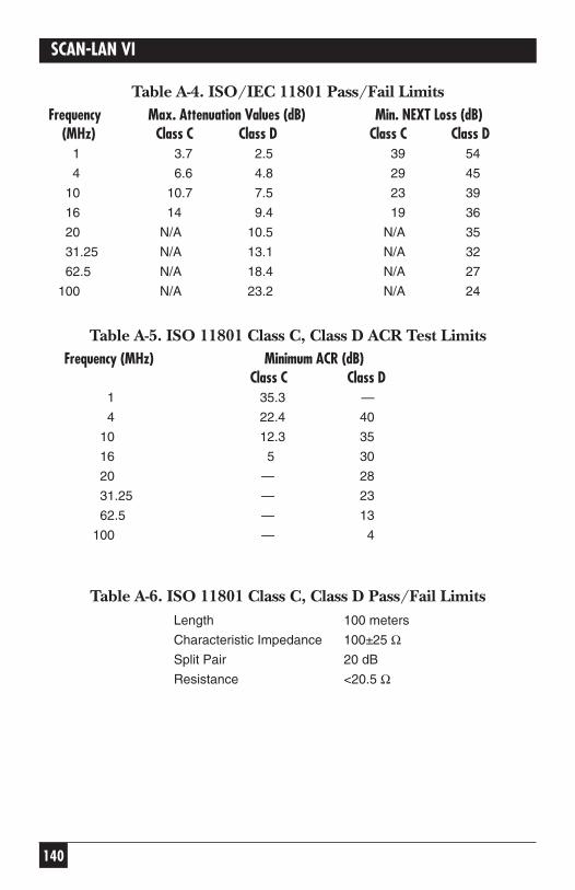
140
SCAN-LAN VI
Table A-4. ISO/IEC 11801 Pass/Fail LimitsFrequency Max. Attenuation Values (dB) Min. NEXT Loss (dB)
(MHz) Class C Class D Class C Class D1 3.7 2.5 39 54
4 6.6 4.8 29 45
10 10.7 7.5 23 39
16 14 9.4 19 36
20 N/A 10.5 N/A 35
31.25 N/A 13.1 N/A 32
62.5 N/A 18.4 N/A 27
100 N/A 23.2 N/A 24
Table A-5. ISO 11801 Class C, Class D ACR Test LimitsFrequency (MHz) Minimum ACR (dB)
Class C Class D1 35.3 —
4 22.4 40
10 12.3 35
16 5 30
20 — 28
31.25 — 23
62.5 — 13
100 — 4
Table A-6. ISO 11801 Class C, Class D Pass/Fail LimitsLength 100 meters
Characteristic Impedance 100±25 ΩSplit Pair 20 dB
Resistance <20.5 Ω
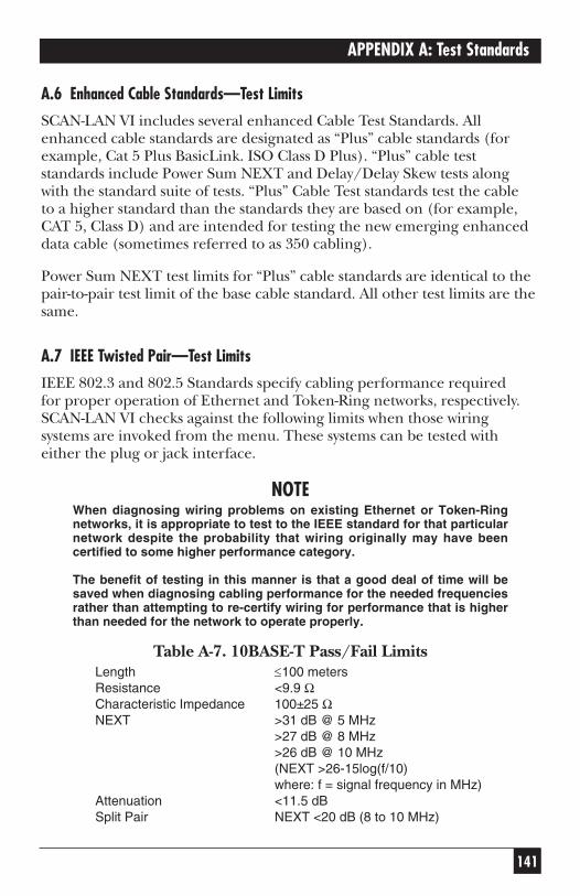
141
APPENDIX A: Test Standards
A.6 Enhanced Cable Standards—Test Limits
SCAN-LAN VI includes several enhanced Cable Test Standards. Allenhanced cable standards are designated as “Plus” cable standards (forexample, Cat 5 Plus BasicLink. ISO Class D Plus). “Plus” cable teststandards include Power Sum NEXT and Delay/Delay Skew tests alongwith the standard suite of tests. “Plus” Cable Test standards test the cable to a higher standard than the standards they are based on (for example,CAT 5, Class D) and are intended for testing the new emerging enhanceddata cable (sometimes referred to as 350 cabling).
Power Sum NEXT test limits for “Plus” cable standards are identical to thepair-to-pair test limit of the base cable standard. All other test limits are thesame.
A.7 IEEE Twisted Pair—Test Limits
IEEE 802.3 and 802.5 Standards specify cabling performance required for proper operation of Ethernet and Token-Ring networks, respectively.SCAN-LAN VI checks against the following limits when those wiringsystems are invoked from the menu. These systems can be tested witheither the plug or jack interface.
NOTEWhen diagnosing wiring problems on existing Ethernet or Token-Ringnetworks, it is appropriate to test to the IEEE standard for that particularnetwork despite the probability that wiring originally may have beencertified to some higher performance category.
The benefit of testing in this manner is that a good deal of time will besaved when diagnosing cabling performance for the needed frequenciesrather than attempting to re-certify wiring for performance that is higherthan needed for the network to operate properly.
Table A-7. 10BASE-T Pass/Fail LimitsLength ≤100 metersResistance <9.9 ΩCharacteristic Impedance 100±25 ΩNEXT >31 dB @ 5 MHz
>27 dB @ 8 MHz>26 dB @ 10 MHz(NEXT >26-15log(f/10)where: f = signal frequency in MHz)
Attenuation <11.5 dBSplit Pair NEXT <20 dB (8 to 10 MHz)
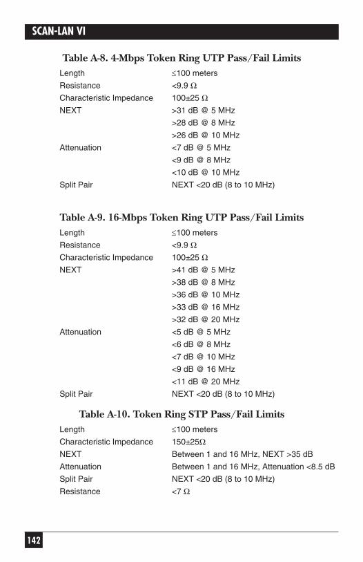
142
SCAN-LAN VI
Table A-8. 4-Mbps Token Ring UTP Pass/Fail LimitsLength ≤100 meters
Resistance <9.9 ΩCharacteristic Impedance 100±25 ΩNEXT >31 dB @ 5 MHz
>28 dB @ 8 MHz
>26 dB @ 10 MHz
Attenuation <7 dB @ 5 MHz
<9 dB @ 8 MHz
<10 dB @ 10 MHz
Split Pair NEXT <20 dB (8 to 10 MHz)
Table A-9. 16-Mbps Token Ring UTP Pass/Fail LimitsLength ≤100 meters
Resistance <9.9 ΩCharacteristic Impedance 100±25 ΩNEXT >41 dB @ 5 MHz
>38 dB @ 8 MHz
>36 dB @ 10 MHz
>33 dB @ 16 MHz
>32 dB @ 20 MHz
Attenuation <5 dB @ 5 MHz
<6 dB @ 8 MHz
<7 dB @ 10 MHz
<9 dB @ 16 MHz
<11 dB @ 20 MHz
Split Pair NEXT <20 dB (8 to 10 MHz)
Table A-10. Token Ring STP Pass/Fail LimitsLength ≤100 meters
Characteristic Impedance 150±25ΩNEXT Between 1 and 16 MHz, NEXT >35 dB
Attenuation Between 1 and 16 MHz, Attenuation <8.5 dB
Split Pair NEXT <20 dB (8 to 10 MHz)
Resistance <7 Ω
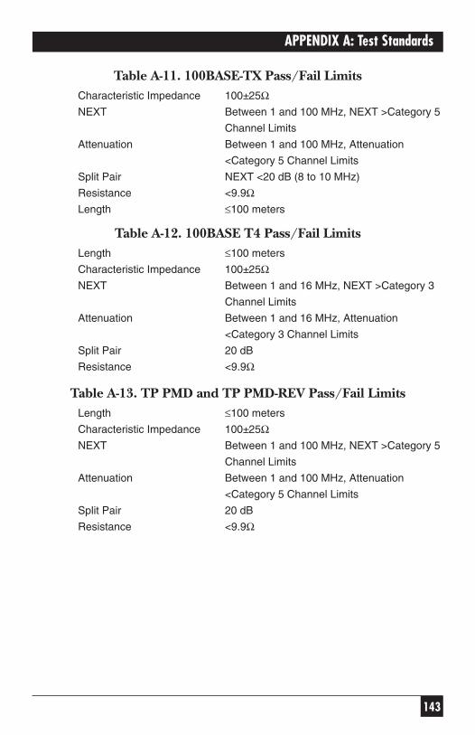
143
APPENDIX A: Test Standards
Table A-11. 100BASE-TX Pass/Fail LimitsCharacteristic Impedance 100±25ΩNEXT Between 1 and 100 MHz, NEXT >Category 5
Channel Limits
Attenuation Between 1 and 100 MHz, Attenuation
<Category 5 Channel Limits
Split Pair NEXT <20 dB (8 to 10 MHz)
Resistance <9.9ΩLength ≤100 meters
Table A-12. 100BASE T4 Pass/Fail LimitsLength ≤100 meters
Characteristic Impedance 100±25ΩNEXT Between 1 and 16 MHz, NEXT >Category 3
Channel Limits
Attenuation Between 1 and 16 MHz, Attenuation
<Category 3 Channel Limits
Split Pair 20 dB
Resistance <9.9Ω
Table A-13. TP PMD and TP PMD-REV Pass/Fail LimitsLength ≤100 meters
Characteristic Impedance 100±25ΩNEXT Between 1 and 100 MHz, NEXT >Category 5
Channel Limits
Attenuation Between 1 and 100 MHz, Attenuation
<Category 5 Channel Limits
Split Pair 20 dB
Resistance <9.9Ω
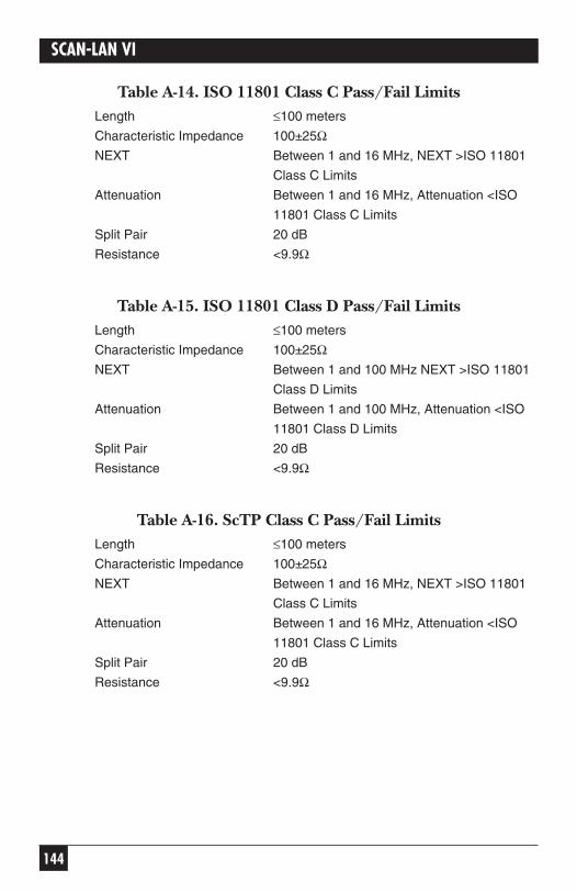
144
SCAN-LAN VI
Table A-14. ISO 11801 Class C Pass/Fail LimitsLength ≤100 meters
Characteristic Impedance 100±25ΩNEXT Between 1 and 16 MHz, NEXT >ISO 11801
Class C Limits
Attenuation Between 1 and 16 MHz, Attenuation <ISO
11801 Class C Limits
Split Pair 20 dB
Resistance <9.9Ω
Table A-15. ISO 11801 Class D Pass/Fail LimitsLength ≤100 meters
Characteristic Impedance 100±25ΩNEXT Between 1 and 100 MHz NEXT >ISO 11801
Class D Limits
Attenuation Between 1 and 100 MHz, Attenuation <ISO
11801 Class D Limits
Split Pair 20 dB
Resistance <9.9Ω
Table A-16. ScTP Class C Pass/Fail LimitsLength ≤100 meters
Characteristic Impedance 100±25ΩNEXT Between 1 and 16 MHz, NEXT >ISO 11801
Class C Limits
Attenuation Between 1 and 16 MHz, Attenuation <ISO
11801 Class C Limits
Split Pair 20 dB
Resistance <9.9Ω
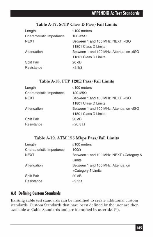
145
APPENDIX A: Test Standards
Table A-17. ScTP Class D Pass/Fail LimitsLength ≤100 meters
Characteristic Impedance 100±25ΩNEXT Between 1 and 100 MHz, NEXT >ISO
11801 Class D Limits
Attenuation Between 1 and 100 MHz, Attenuation <ISO
11801 Class D Limits
Split Pair 20 dB
Resistance <9.9Ω
Table A-18. FTP 120Ω Pass/Fail LimitsLength ≤100 meters
Characteristic Impedance 120±25ΩNEXT Between 1 and 100 MHz, NEXT >ISO
11801 Class D Limits
Attenuation Between 1 and 100 MHz, Attenuation <ISO
11801 Class D Limits
Split Pair 20 dB
Resistance <20.5 Ω
Table A-19. ATM 155 Mbps Pass/Fail LimitsLength ≤100 meters
Characteristic Impedance 100ΩNEXT Between 1 and 100 MHz, NEXT >Category 5
Limits
Attenuation Between 1 and 100 MHz, Attenuation
<Category 5 Limits
Split Pair 20 dB
Resistance <9.9Ω
A.8 Defining Custom Standards
Existing cable test standards can be modified to create additional customstandards. Custom Standards that have been defined by the user are thenavailable as Cable Standards and are identified by asterisks (*).
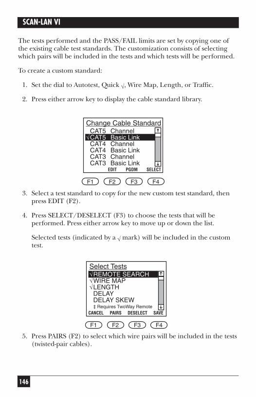
146
SCAN-LAN VI
The tests performed and the PASS/FAIL limits are set by copying one ofthe existing cable test standards. The customization consists of selectingwhich pairs will be included in the tests and which tests will be performed.
To create a custom standard:
1. Set the dial to Autotest, Quick √, Wire Map, Length, or Traffic.
2. Press either arrow key to display the cable standard library.
3. Select a test standard to copy for the new custom test standard, thenpress EDIT (F2).
4. Press SELECT/DESELECT (F3) to choose the tests that will beperformed. Press either arrow key to move up or down the list.
Selected tests (indicated by a √ mark) will be included in the customtest.
5. Press PAIRS (F2) to select which wire pairs will be included in the tests(twisted-pair cables).
√√√
CANCEL PAIRS DESELECT SAVE
Select Tests
F1 F2 F3 F4
REMOTE SEARCHWIRE MAPLENGTHDELAYDELAY SKEW‡ Requires TwoWay Remote
√
EDIT PGDM SELECT
Change Cable Standard
F1 F2 F3 F4
CAT5 ChannelCAT5 Basic LinkCAT4 ChannelCAT4 Basic LinkCAT3 ChannelCAT3 Basic Link
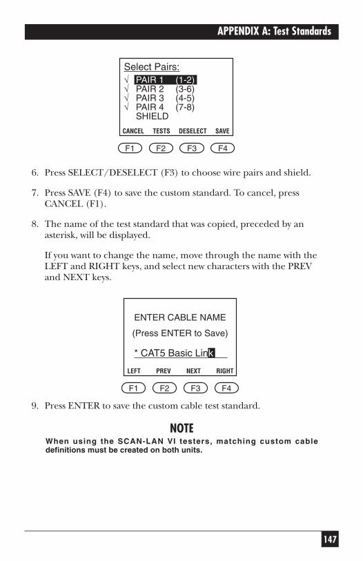
147
APPENDIX A: Test Standards
6. Press SELECT/DESELECT (F3) to choose wire pairs and shield.
7. Press SAVE (F4) to save the custom standard. To cancel, pressCANCEL (F1).
8. The name of the test standard that was copied, preceded by anasterisk, will be displayed.
If you want to change the name, move through the name with theLEFT and RIGHT keys, and select new characters with the PREV and NEXT keys.
9. Press ENTER to save the custom cable test standard.
NOTEWhen using the SCAN-LAN VI testers, matching custom cabledefinitions must be created on both units.
LEFT PREV NEXT RIGHT
* CAT5 Basic Link nn
F1 F2 F3 F4
ENTER CABLE NAME
(Press ENTER to Save)
√√√√
CANCEL TESTS DESELECT SAVE
Select Pairs:
F1 F2 F3 F4
PAIR 1 (1-2)PAIR 2 (3-6)PAIR 3 (4-5)PAIR 4 (7-8)SHIELD
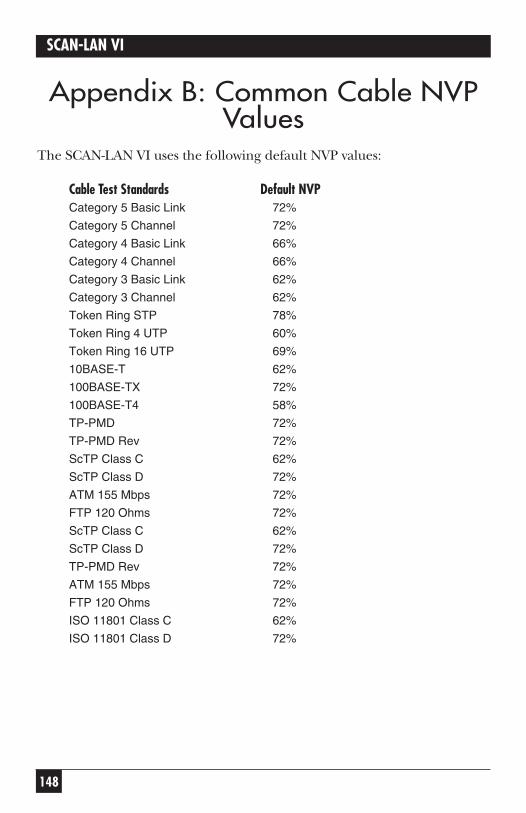
148
SCAN-LAN VI
Appendix B: Common Cable NVPValues
The SCAN-LAN VI uses the following default NVP values:
Cable Test Standards Default NVPCategory 5 Basic Link 72%
Category 5 Channel 72%
Category 4 Basic Link 66%
Category 4 Channel 66%
Category 3 Basic Link 62%
Category 3 Channel 62%
Token Ring STP 78%
Token Ring 4 UTP 60%
Token Ring 16 UTP 69%
10BASE-T 62%
100BASE-TX 72%
100BASE-T4 58%
TP-PMD 72%
TP-PMD Rev 72%
ScTP Class C 62%
ScTP Class D 72%
ATM 155 Mbps 72%
FTP 120 Ohms 72%
ScTP Class C 62%
ScTP Class D 72%
TP-PMD Rev 72%
ATM 155 Mbps 72%
FTP 120 Ohms 72%
ISO 11801 Class C 62%
ISO 11801 Class D 72%
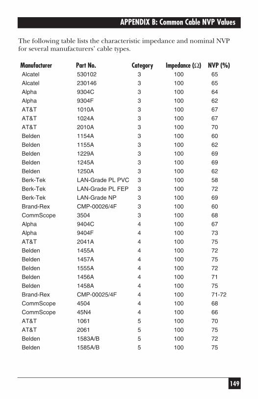
149
APPENDIX B: Common Cable NVP Values
The following table lists the characteristic impedance and nominal NVPfor several manufacturers’ cable types.
Manufacturer Part No. Category Impedance (Ω) NVP (%)Alcatel 530102 3 100 65
Alcatel 230146 3 100 65
Alpha 9304C 3 100 64
Alpha 9304F 3 100 62
AT&T 1010A 3 100 67
AT&T 1024A 3 100 67
AT&T 2010A 3 100 70
Belden 1154A 3 100 60
Belden 1155A 3 100 62
Belden 1229A 3 100 69
Belden 1245A 3 100 69
Belden 1250A 3 100 62
Berk-Tek LAN-Grade PL PVC 3 100 58
Berk-Tek LAN-Grade PL FEP 3 100 72
Berk-Tek LAN-Grade NP 3 100 69
Brand-Rex CMP-00026/4F 3 100 60
CommScope 3504 3 100 68
Alpha 9404C 4 100 67
Alpha 9404F 4 100 73
AT&T 2041A 4 100 75
Belden 1455A 4 100 72
Belden 1457A 4 100 75
Belden 1555A 4 100 72
Belden 1456A 4 100 71
Belden 1458A 4 100 75
Brand-Rex CMP-00025/4F 4 100 71-72
CommScope 4504 4 100 68
CommScope 45N4 4 100 66
AT&T 1061 5 100 70
AT&T 2061 5 100 75
Belden 1583A/B 5 100 72
Belden 1585A/B 5 100 75
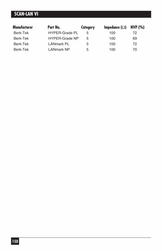
150
SCAN-LAN VI
Manufacturer Part No. Category Impedance (Ω) NVP (%)Berk-Tek HYPER-Grade PL 5 100 72
Berk-Tek HYPER-Grade NP 5 100 69
Berk-Tek LANmark PL 5 100 72
Berk-Tek LANmark NP 5 100 70

151
APPENDIX C: Optional Accessories
Appendix C: Optional AccessoriesThe following accessories may be ordered separately from Black Box.
ACCESSORY PART NO.Modular Jack Performance Module TS692
Coax Performance Module TS693
Battery Eliminator, Rechargeable NiMH TS694
Carrying case, softside TS695
152
SCAN-LAN VI
Appendix D: Cable ReplacementProcedure
D.1 General
The Modular Plug Performance Module shipped with your SCAN-LAN VIfeatures a user-replaceable test cord. This Performance Module is a criticalpart of a SCAN-LAN VI. The SCAN-LAN VI uses frequencies up to100 MHz, where 1 inch of wire is a significant part of a wavelength. Properwire preparation and pair twisting is extremely important to preservemeasurement accuracy. Follow the procedures carefully including re-calibration and testing.
D.2 Equipment
CABLE REQUIRED
Preferred: Pre-tested replacement cable from Black Box. These cableshave been tested for Near-End Crosstalk and other criticalparameters and have had wire ends prepared for directinstallation.
Or: EIA/TIA T568A Category 5 patch cord, 8-ft. length, cut in two
Or: 4-ft. Category 5 patch cord, with one connector removed.
TOOLS REQUIRED
• Tie wrap—approximately 0.14 inch wide x 3 inch minimum length(3.6 mm x 7.5 cm)
• Screwdriver—flat blade 0.10 inch (2.5 mm)
• Side-cut pliers (dikes)
• Wire-stripping tool
• Knife.
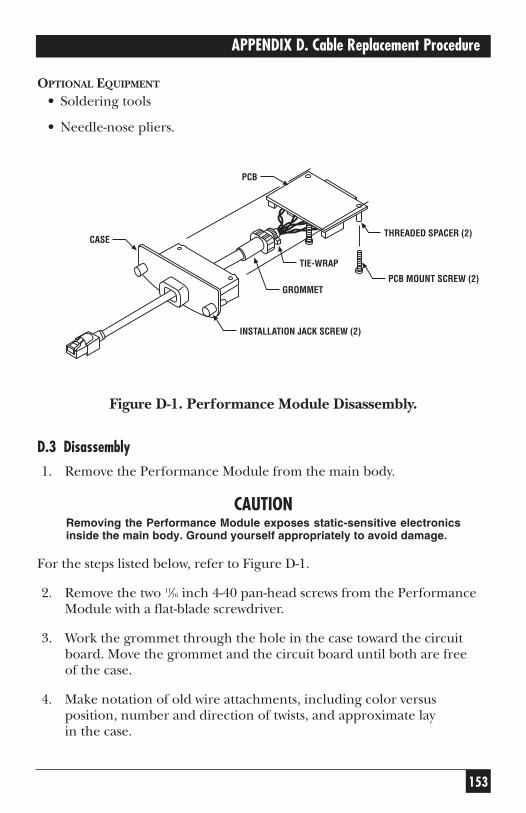
153
APPENDIX D. Cable Replacement Procedure
OPTIONAL EQUIPMENT
• Soldering tools
• Needle-nose pliers.
Figure D-1. Performance Module Disassembly.
D.3 Disassembly
1. Remove the Performance Module from the main body.
CAUTIONRemoving the Performance Module exposes static-sensitive electronicsinside the main body. Ground yourself appropriately to avoid damage.
For the steps listed below, refer to Figure D-1.
2. Remove the two 11⁄16 inch 4-40 pan-head screws from the PerformanceModule with a flat-blade screwdriver.
3. Work the grommet through the hole in the case toward the circuitboard. Move the grommet and the circuit board until both are free of the case.
4. Make notation of old wire attachments, including color versusposition, number and direction of twists, and approximate lay in the case.
TIE-WRAP
GROMMET
INSTALLATION JACK SCREW (2)
PCB MOUNT SCREW (2)
THREADED SPACER (2)
PCB
CASE
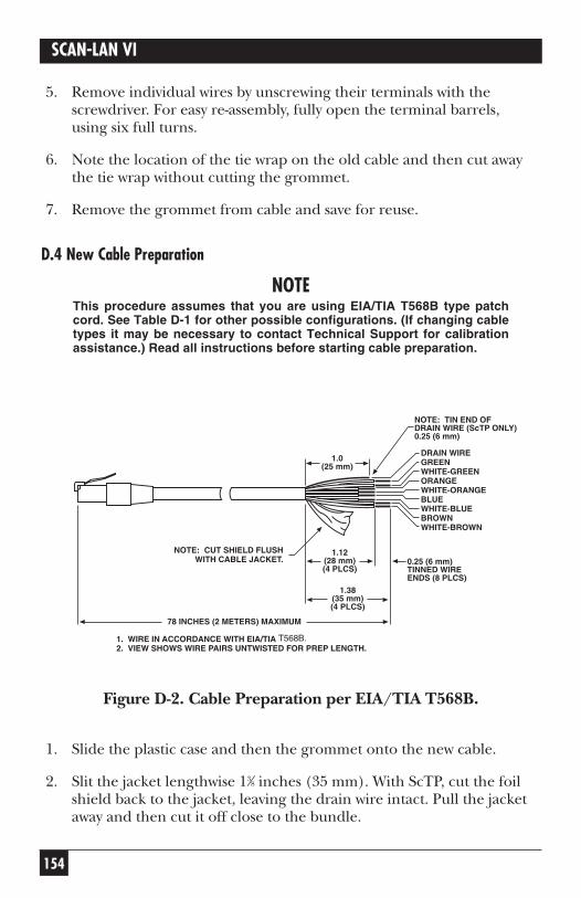
154
SCAN-LAN VI
5. Remove individual wires by unscrewing their terminals with thescrewdriver. For easy re-assembly, fully open the terminal barrels, using six full turns.
6. Note the location of the tie wrap on the old cable and then cut awaythe tie wrap without cutting the grommet.
7. Remove the grommet from cable and save for reuse.
D.4 New Cable Preparation
NOTEThis procedure assumes that you are using EIA/TIA T568B type patchcord. See Table D-1 for other possible configurations. (If changing cabletypes it may be necessary to contact Technical Support for calibrationassistance.) Read all instructions before starting cable preparation.
Figure D-2. Cable Preparation per EIA/TIA T568B.
1. Slide the plastic case and then the grommet onto the new cable.
2. Slit the jacket lengthwise 13⁄8 inches (35 mm). With ScTP, cut the foilshield back to the jacket, leaving the drain wire intact. Pull the jacketaway and then cut it off close to the bundle.
78 INCHES (2 METERS) MAXIMUM
1.12(28 mm)(4 PLCS)
1. WIRE IN ACCORDANCE WITH EIA/TIA T568A.2. VIEW SHOWS WIRE PAIRS UNTWISTED FOR PREP LENGTH.
NOTE: CUT SHIELD FLUSHWITH CABLE JACKET.
1.38(35 mm)(4 PLCS)
0.25 (6 mm)TINNED WIREENDS (8 PLCS)
1.0(25 mm)
NOTE: TIN END OFDRAIN WIRE (ScTP ONLY)0.25 (6 mm)
DRAIN WIREGREENWHITE-GREENORANGEWHITE-ORANGEBLUEWHITE-BLUEBROWNWHITE-BROWN
T568B.
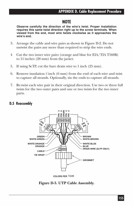
155
APPENDIX D. Cable Replacement Procedure
NOTEObserve carefully the direction of the wire’s twist. Proper installationrequires this same twist direction right up to the screw terminals. Whenviewed from the end, most wire twists clockwise as it approaches thewire’s end.
3. Arrange the cable and wire pairs as shown in Figure D-2. Do notuntwist the pairs any more than required to strip the wire ends.
4 Cut the two inner wire pairs (orange and blue for EIA/TIA T568B) to 11⁄8 inches (28 mm) from the jacket.
5. If using ScTP, cut the bare drain wire to 1 inch (25 mm).
6. Remove insulation 1⁄4 inch (6 mm) from the end of each wire and twistto capture all strands. Optionally, tin the ends to capture all strands.
7. Re-twist each wire pair in their original direction. Use two or three fulltwists for the two outer pairs and one or two twists for the two innerparts.
D.5 Reassembly
Figure D-3. UTP Cable Assembly.
BROWNWHITE-BROWN
WHITE-BLUEBLUEDRAIN WIRE (ScTP ONLY)
GREENWHITE-GREEN
WHITE-ORANGEORANGE
CABLE
TIE WRAP
COLORS PER T568A
GROMMET
PIN
3
PIN
6
DR
AIN
PIN
4
PIN
5
PIN 7
PIN 8PIN 1PIN 2
T568B
156
SCAN-LAN VI
1. Insert each wire into its terminal and tighten screw until snug (seeFigure D-3). If you’re using ScTP, connect the drain wire to the centerscrew terminal of the center terminal strip.
2. Check to see that there are no stray wire strands outside terminalclamps and make sure all wires are properly tightened into theirterminals.
3. Make sure that each pair twist is correct, and that the four wire pairsexit radially from the cable jacket as before. Rotate the entire cable sothe fan of wires is flat and parallel to the circuit board.
4. Slide the grommet until 1⁄32 inch (0.8 mm) or less of cable jacket isexposed (see Figure 1-1). Rotate the grommet so that its flats areparallel with the circuit board when the fanned wires are flat to thecircuit board.
Install new tie wrap centered on grommet sleeve as shown in FigureD-3. When the tie wrap is finally tightened, its ratchet box should beapproximately in the plane of the wire fan.
5. Tighten tie wrap as much as possible (until wrap material begins tostretch). Cut off excess tie wrap.
6. Carefully guide the grommet and circuit board into the case. Once thecylindrical neck on the grommet is through the hole, use the neck topull the grommet into place. The twisted pairs will bunch up whenproperly installed. If necessary change their positions to avoidpinching.
NOTEIf using ScTP, the drain wire must not short against the circuit shieldnor the case (if case is copper painted). Shorten the drain wire bycutting as required to accomplish clearance.
7. Reinstall the 4-40 screws from the open side of the case. Make sure thescrews extend through the circuit board and into the plastic of thecase.
8. Reinstall the Performance Module in the SCAN-LAN VI body byalternately turning each knurled thumbscrew a small amount orturning them simultaneously. Only tighten these screws finger-tight.
157
APPENDIX D. Cable Replacement Procedure
9. Connect the remote and run the WIREMAP test using the CAT 5 Basic Link Cable standard to make sure the new cable was installedcorrectly. (If the 12/36 pairs are crossed you probably wired up a 568Bcable as a 568A or vice versa. Swap the Orange and Green pairs. SeeTable D-1.)
D.6 Recalibration
1. Calibrate Performance Module. Follow the procedures in Chapter 10for Performance Module Calibration.
NOTEIn addition to calibrating, this step checks the NEXT to ensure that yournew cable assembly is similar in quality to factory specifications. If yourassembly fails this test, re-examine the twisted pairs as they enter thescrew terminals. Try twisting the wires tighter and make sure the twistsextend as close as possible to the screw terminals. Sometimes movingthe pairs is all that is required. Many CAT 5 patch cables have too muchNEXT due to the way they are terminated at the plug end. You may needto try several before finding one that passes this test. Pre-tested cablesare available from Black Box.
2. Calibrate Remote. Follow the Remote Unit Calibration procedure,also in Chapter 10.
3. System Check. Check your SCAN-LAN VI performance by turning thedial to EXTENDED FUNCTIONS. Run Self-Test. All results shouldread PASS. Run Pair Reversal Test. Results should read PASS.
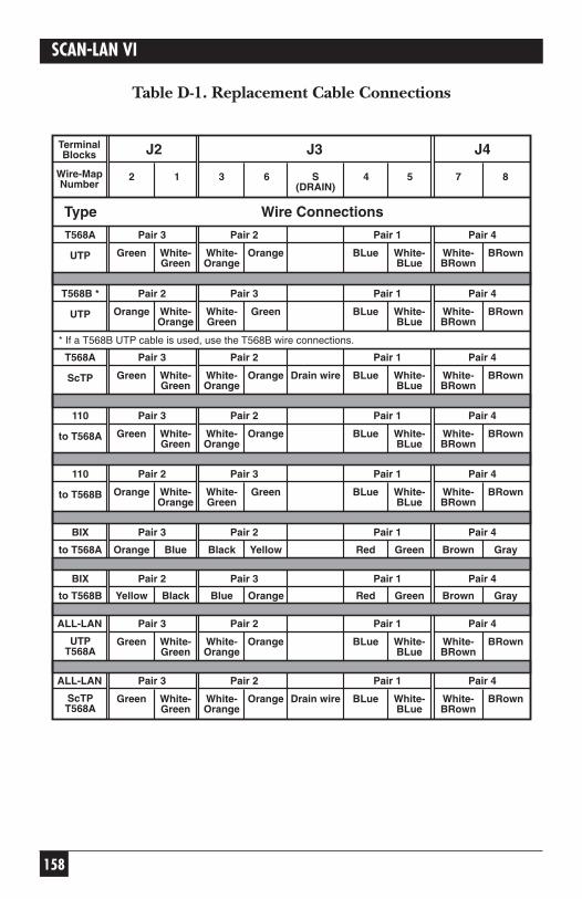
158
SCAN-LAN VI
Table D-1. Replacement Cable Connections
UTP
T568A
Type
Pair 3
Green White-Green
Wire Connections
Pair 2
White-Orange
Orange
Pair 1
BLue White-BLue
Pair 4
White-BRown
BRown
J2 J4J3
S(DRAIN)
2 1 3 6 4 5 7 8
TerminalBlocks
Wire-MapNumber
UTP
T568B * Pair 2
Orange White-Orange
Pair 3
White-Green
Green
Pair 1
BLue White-BLue
Pair 4
White-BRown
BRown
ScTP
T568A Pair 3
Green White-Green
Pair 2
White-Orange
Orange
Pair 1
BLue White-BLue
Pair 4
White-BRown
BRownDrain wire
* If a T568B UTP cable is used, use the T568B wire connections.
to T568A
110 Pair 3
Green White-Green
Pair 2
White-Orange
Orange
Pair 1
BLue White-BLue
Pair 4
White-BRown
BRown
to T568B
110 Pair 2
Orange White-Orange
Pair 3
White-Green
Green
Pair 1
BLue White-BLue
Pair 4
White-BRown
BRown
to T568A
BIX Pair 3
Orange Blue
Pair 2
Black Yellow
Pair 1
Red Green
Pair 4
Brown Gray
to T568B
BIX Pair 2
Yellow Black
Pair 3
Blue Orange
Pair 1
Red Green
Pair 4
Brown Gray
UTPT568A
ALL-LAN Pair 3
Green White-Green
Pair 2
White-Orange
Orange
Pair 1
BLue White-BLue
Pair 4
White-BRown
BRown
ScTPT568A
ALL-LAN Pair 3
Green White-Green
Pair 2
White-Orange
Orange
Pair 1
BLue White-BLue
Pair 4
White-BRown
BRownDrain wire
159
GLOSSARY
GlossaryAC (Alternating Current) — A voltage or current of alternating polarity.
Access Unit — A unit that allows multiple-device attachment at a centrallocation.
Address — An identification code assigned uniquely to each device or workstation connected to a network.
Analog — A continuously varying signal that can take on any voltage or current level.
Anomaly — An impedance discontinuity causing an undesired signalreflection on a transmission cable.
ANSI — American National Standards Institute.
ARCNET (Attached Resources Computing Network) — A token busdeveloped by Datapoint.
ATM (Asynchronous Transfer Mode) — A high-speed packet-switchingmethod.
Attenuation — Reduction in the strength or power of a signal as it travelsover the length of a cable.
Attenuation to Crosstalk Ratio (ACR) — An indication of the reliability ofdata communications through a network. It is a computed value basedupon the measured values of attenuation and NEXT.
AUI (Attachment Unit Interface) — Connects the transceiver and NetworkInterface Card in 10BASE5 networks.
AWG (American Wire Gauge) — The thickness of the conductor in a cable.
Backbone — A central local area network used to interconnect two ormore other local area networks.
Balun — A cable-impedance-matching RF transformer.
Bandwidth — The difference between the highest and lowest frequencyavailable on a channel to effectively transmit signals.
160
SCAN-LAN VI
Barrel Connector — Connector that joins two sections of a coax cable.
Baseband — A frequency band that uses the complete bandwidth of a cabledown to zero frequency for the transmission of a single channel of data.
Basic Link — As defined by EIA/TIA TSB-67, the horizontal wiring linkfrom the work-area telecommunications outlet (wallplate) to thehorizontal cross-connect. Includes equipment cords at each end forconnection to test instrumentation.
BER (Bit Error Rate) — The ratio of received bits in error to the totalreceived bits.
Binary — A signaling method that uses two states, either zero or one.
Bit — Binary digit, the smallest unit of data.
Bits per Second (bps) — A measurement of the speed of data transmission.
Block — A connection system for cross-connecting twisted-pairtelecommunication cable. Also called punchdown block. Common typesinclude AT&T 110 and 66 blocks.
BNC — Bayonet Neil Concelman connector, the connector used forcoaxial cable in a Thin Ethernet network.
Bridge — Attachment device that forwards packets from one LAN segmentto another based upon destination MAC address.
Broadband — A wide-bandwidth signaling method that allows a cable tocarry several different kinds of transmissions simultaneously such as voice,video, and data on one cable.
Bus — A configuration in which nodes on a network are interconnectedand communicate.
Byte — Eight data bits.
Cable — A medium that is used to interconnect two or more devices forcommunication.
Capacitance — The ability to store an electrical charge between twosurfaces, measured in farads.
161
GLOSSARY
CDDI — Copper Distributed Data Interface, a variation of the FDDIstandard (ANSI X3T9.5) adapted for 100-Mbps data transmission ontwisted-pair cable. Also called TP-PMD.
Channel — As defined by EIA/TIA TSB-67, the entire horizontal wiringlink connecting end devices in the work area to the hub/concentrator inthe wiring closet. Includes user’s equipment cords at both ends andhorizontal cross-connections (see Appendix A, Test Standards, Figure A-1).
Characteristic Impedance — An inherent characteristic of the cable. Ameasure of resistance to AC current flow (high frequency) by a long cable.
Cheapernet — A nickname for 10BASE2 or ThinNet, a coax-basedEthernet network.
Coaxial (Coax) Cable — A cable that contains a single center copperconductor surrounded by insulation material and one or more layers of metal foil or braided-wire mesh plus an outer protective jacket.
Collision — The result of two stations simultaneously attempting totransmit data on a shared network transmission medium.
Concentrator — A piece of LAN equipment that allows multiple networkdevices to be connected to the network cabling system through a centralpoint. Also called a hub.
Connecting Block — An interconnecting point for several LAN segments.
Crossed Pair — A twisted-pair wiring error in which a wire pair on oneconnector of the cable is wired to a different pair on the other end of thecable.
Crosstalk — The coupling of a signal between pairs of a multiple-pair cable.
CSA — Canadian Standards Association.
CSMA/CD (Carrier Sense Multiple Access/Collision Detection) —Ethernet media access method in which stations transmit on a buswhenever the medium is available and re-transmit when collisions occur.
Decibel (dB) — A logarithmic unit of measure used to express theamplitude ratio between two signals. dB = 20 log (Vsignal2/Vsignal1).
DC (Direct Current) — A zero-frequency or constant-level signal.
162
SCAN-LAN VI
DECnet — A proprietary Ethernet LAN developed by Digital EquipmentCorporation.
Delay — A measure of the time electrical signals take to propagate fromone end of the cable to the other end.
Delay Skew — The difference in propagation delays from one cable pair to another.
Differential Manchester Encoding — A digital signaling technique with a transition in the middle of the bit to provide clocking.
Drop Cable — In 10BASE5 networks, a cable connecting a workstationnetwork interface card (NIC) with the transmission medium. Sometimescalled Attachment Unit Interface (AUI) cable.
EIA — Electronic Industry Association.
EMI (Electromagnetic Interference) — Leakage of electromagnetic energyoutside of a transmission medium.
Ethernet — A high-speed local area network using the Carrier SenseMultiple Access with Collision Detection (CSMA/CD) media-accessmethod.
Far End Crosstalk (FEXT) — Crosstalk that is measured at the oppositeend of a cable from where the signal is injected.
Fault — Any accidental condition that causes a component to fail.
FCC—Federal Communications Commission.
FDDI (Fiber Distributed Data Interface) — A network standard (ANSIX3T9.5) that defines a 100-Mbps token-ring network using optical fiber for data transmission over distances of several kilometers.
Fiber — A transmission medium designed to transmit data in the form of light pulses.
File Server — A high-capacity file-storage device that computers on a network can access to retrieve files.
Foil Twisted Pair (FTP) — See Screened Twisted Pair.
Frame — A unit of transmission in some LANs such as Token Ring.
163
GLOSSARY
Frequency — Rate of AC signal alternation, defined in Hertz (cycles persecond).
Full Duplex — Transmission of data in both directions at the same time.
Gateway — A device that interconnects two or more networks that may usedifferent protocols and media.
Hertz (Hz) — Unit of measure for frequency in cycles per second (cps).
Horizontal Cable — The part of a building’s cabling that extends from and includes the telecommunications outlet in the work area to thetelecommunications (IDF) closet on the same floor.
Hub — A piece of LAN equipment that allows multiple network devices tobe connected to the network cabling system through a central point. Alsocalled a concentrator.
I/O — Input/Output.
IDF (Intermediate Distribution Frame) — The distribution point wherevertical backbone cable is connected to the horizontal cables.
IEEE — Institute of Electrical and Electronic Engineers.
Impedance — A frequency-dependent parameter defined by the ratio of the AC Voltage to Current across a circuit element.
Impulse Noise — Non-repetitive electrical spikes or pulses caused byexternal electromagnetic fields.
Inductance — The ability to store a magnetic field across a conductormeasured in Henries (H).
Insulation — A non-conductive material used to isolate conductor surfaces.
Internetworking — Communication among devices across multiplenetworks.
ISO — International Organization for Standardization.
Jabber — A network fault condition where one station is continuously trans-mitting or transmits illegal packets of length greater than 20 milliseconds.
164
SCAN-LAN VI
Jack — EIA-standard modular connector for connecting twisted-pair cablesat a wall plate or patch panel.
Jacket — The outside protective covering of a cable.
Jitter — The time-based variation of the received data bits.
Jumper Cable — Short cable for interconnecting connecting blocks orpatch panels. Also called patch cord or patch cable.
LAN (Local Area Network) — A data-communication network thatprovides high-speed communication in a moderate-size geographic area.
Link — The communications medium connecting office equipment to thehub or concentrator in the wiring closet.
Link Pulse — A single-bit test pulse transmitted periodically between hubsand workstations on 10BASE-T segments to verify integrity.
Lobe — The cable segments that connect a device to the Multi-StationAccess Unit (MSAU) for Token Ring.
MAC (Medium Access Control) — The method of determining howstations access the medium at any time.
MAC Address — A unique identification number assigned to each stationconnected to a network. Sometimes called Station Address.
Main Cross-Connects — The connections between externaltelecommunications lines, interbuilding backbone cable, commoncommunications equipment (PBX), and internal backbone cable. Alsocalled Main Distribution Frame.
Main Distribution Frame (MDF) — See Main Cross-Connects.
Medium — The physical carrier of the data being transmitted (for exampletwisted-pair cable, coaxial cable, or fiber).
Medium Attachment Unit (MAU) — Device used in Ethernet networks tocouple a station or hub to the transmission medium.
Modular Jack — EIA-standard receptacle connector used for connectingtwisted-pair cables at a wall plate, patch panels, and station equipment.Sometimes called RJ-45 jack.
165
GLOSSARY
Modular Plug — EIA-standard connector used to terminate twisted-pairpatch cables and equipment cables. Sometimes called RJ-45 plug.
MSAU (Multi-Station Access Unit) — A Token Ring wiring center fornetwork attachment.
MTBF (Mean Time Between Failures) — The average operation time tocomponent failures.
Near-End Crosstalk (NEXT) — Noise coupled between two twisted pairsmeasured at the same end of the cable as the disturbing signal source.
Network — A collection of nodes interconnected by a medium.
Network Interface Card (NIC) — The circuit card that interfaces a stationto the network.
Network Manager — A program that is used to monitor, manage, anddiagnose the problems of a network medium.
Node — Connecting point on a network. A station or device on a network.
Noise — Any random disturbance in a communications system thatinterferes with the integrity of the transmitted data.
NVP (Nominal Velocity of Propagation) — The speed of signal propagationthrough a cable, expressed as a percentage of the speed of light in a vacuum.
Ohm — The unit of measurement for resistance.
Open — A break in the connection between the two ends of a wire or cable.
OSI (Open Systems Interconnect) — A seven-layer architecture that servesas a model between systems.
Packet — A group of bits in a defined format, containing data and controlinformation used for transmission from one node to another.
Pair — Two wires in a multi-wired cable that are used as a singletransmission path.
Passive Concentrator — A type of Multi-Station Access Unit (MSAU) usedto connect stations to a Token-Ring network without signal regeneration.
166
SCAN-LAN VI
Patch Cable — A short length of cable with modular-plug connectors at both ends that is used to complete a cable segment.
Patch Panel — An organized concentration of modular-cable connectorsthat facilitates the interconnection of cable segments.
Physical Layer — The layer that provides the mechanical, electrical, and functional connection over a transmission medium.
Plenum — An air-handling space inside a building. Plenum cable iscertified for installation in these open spaces.
Plug — A connector designed to insert into a receptacle (jack) of a socket.
Port — An access point for data I/O.
Power Sum NEXT — A sum of the pair-to-pair NEXT coupled from alladjacent pairs in a cable.
Protocol — A standard set of rules specifying the format, timing, andsequencing for data transmission.
Punch-Down Block — A block of mechanical devices that is used toconnect twisted-pair cable.
PVC — Polyvinyl Chloride, a standard coating used on cables.
Receiver — The portion of a station or node that receives the datacommunication.
Repeater — A device that regenerates the data signal, used to extend thenetwork length.
Resistance — An electrical element that impedes the flow of current,measured in ohms.
Reversed Pair — Twisted-pair wiring error in which the polarity of one wirepair is reversed at one end of the link. Also called tip/ring reversal.
Ring — A LAN topology in which data is passed from station to station viaa loop. Also, the designation for one conductor of a twisted-pair cable.
RJ-45 (Registered Jack) — An eight-position telephone-type connector.
167
GLOSSARY
Router — A device that interconnects two or more LAN subnetworks and relays packets based upon destination network addresses.
Runt Packet — An Ethernet packet that is shorter than the minimum validlength (64 bytes).
Screened Twisted Pair (ScTP) — Cable constructed of four twisted-wirepairs surrounded by a metal foil shield and an outer protective jacket. Also called Foil Twisted Pair (FTP).
Sheath — The outside covering of a cable(s).
Shield — A conductive material that is used to enclose a data cable todecrease emissions and noise susceptibility.
Shielded Twisted Pair (STP) — Cable constructed of up to four twisted-wire pairs, each pair individually surrounded by a metal foil, and all wirepairs surrounded by a metal shield plus an outer protective jacket.
Short — A near-zero-resistance connection between two wires of a cable.
Signal to Crosstalk (SCR) — The logarithmic ratio of the received signal to any signal that is coupled into the pair.
Signal to NEXT (SNR) — The logarithmic ratio of the received signal tothe near-end crosstalk that is coupled into the pair.
Signal to Noise (SNR) — The logarithmic ratio of the received signal toany noise.
Silver Satin — Flat untwisted telephone-station wire. Also called quad wire.
Split Pair — A twisted-pair wiring error in which pin-to-pin continuity ismaintained, but physical pairs are separated.
Star — A physical layout of a LAN that uses a centralized wiring location.
Starlan — A LAN network developed by AT&T.
Station — A communication device or node attached to a LAN.
STP — Shielded Twisted Pair.
Tap — A connection to a coax cable that allows access to the network.
168
SCAN-LAN VI
T Connection — A three-way BNC-type connector used to connect coaxialcable to a station network interface card in a 10BASE2 Ethernet network.
TCP/IP (Transmission Control Protocol/Internet Protocol) — A protocoloriginally defined by the U.S. Department of Defense.
TDR (Time-Domain Reflectometry) — A technique for measuring cablelengths by timing the duration between an incident pulse and the reflectedpulse from an impedance discontinuity on a cable.
Telecommunications Closet — A room used to interconnect horizontalcable links to communication distribution equipment. Also called wiringcloset.
Terminator — A connection to the end of a cable which is intended to match the characteristic impedance of the cable.
ThickNet — 10BASE5 Ethernet.
ThinNet — 10BASE2 Ethernet. Sometimes called Cheapnet.
TIA — Telecommunications Industry Association.
Tip — One conductor of a twisted-pair cable.
Token — A sequence of bits transmitted over a Ring or Bus network usedto signify permission to transmit.
TP-PMD (Twisted Pair Physical Media Dependent) — A variation of theFDDI standard (ANSI X3T9.5) adapted for 100-Mbps data transmission on twisted-pair cable. Also called CDDI.
Traffic — Data-transmission activity on a network.
Transceiver — A station-access unit for coax networks.
Transceiver Cable — A cable used to attach a device to an Ethernetsegment.
Tree — A LAN topology where the cable branches from a headend.
Twinaxial Cable — A cable typically used for connecting IBM® systems36/38 and AS/400® equipment. Consists of two center copper conductorssurrounded by insulation material, a braided wire mesh shield, and anouter protective jacket.
169
GLOSSARY
Twisted Pair — A transmission medium using a pair of wires that aretwisted together.
UL® — Underwriter’s Laboratories.
UTP (Unshielded Twisted Pair cable) — Cable constructed of four twistedwire pairs surrounded by an outer protective jacket.
Voice Grade Cable — A lower quality or category of cable used to carrytelephone communication.
Voltage — The potential difference between two points.
Wide Area Networks (WAN) — Networks, usually in the public domain,that tie together widely separated computing devices or LANs.
Wiring Closet — A room used to interconnect horizontal cable links and locate communication distribution equipment. Also calledtelecommunications closet.
Word — Data bits assembled in a convenient processing size.
Workstation — A user’s computer that can be connected to a network.

1000 Park Drive • Lawrence, PA 15055-1018 • 724-746-5500 • Fax 724-746-0746
© Copyright 1999. Black Box Corporation. All rights reserved.