Embed Size (px)
Citation preview
800TRM-002 Page 1 of 21 March 2007
Proteus Industries Inc.
800 & 800NM SERIES METERING FLOW SWITCHES
TECHNICAL REFERENCE MANUAL

800TRM-002 Page 2 of 21 March 2007
Table of Contents
Section Page
1. Introduction 2
2. Features and functions 2
3. How the flow sensor works 7
4. Specifications and performance 8
5. Product certifications 9
6. Installation 9
Mechanical 9
Electrical 13
7. Selecting Trip Points 14
8. Measuring Flow Rate 16
9. Digital Displays 16
10. Cleaning and Maintenance 18
11. Calibration & Recalibration 20
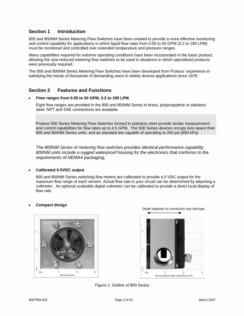
Section 1 Introduction 800 and 800NM Series Metering Flow Switches have been created to provide a more effective monitoring and control capability for applications in which liquid flow rates from 0.05 to 50 GPM (0.2 to 190 LPM) must be monitored and controlled over extended temperature and pressure ranges.
Many capabilities required for extreme operating conditions have been incorporated in the basic product, allowing the size-reduced metering flow switches to be used in situations in which specialized products were previously required.
The 800 and 800NM Series Metering Flow Switches have been developed from Proteus’ experience in satisfying the needs of thousands of demanding users in widely diverse applications since 1978.
Section 2 Features and Functions • Flow ranges from 0.05 to 50 GPM, 0.2 to 190 LPM.
Eight flow ranges are provided in the 800 and 800NM Series in brass, polypropylene or stainless steel. NPT and SAE connections are available.
Proteus 500 Series Metering Flow Switches formed in stainless steel provide similar measurement and control capabilities for flow rates up to 4.5 GPM. The 500 Series devices occupy less space than 800 and 800NM Series units, and as standard are capable of operating to 250 psi (690 kPa).
The 800NM Series of metering flow switches provides identical performance capability. 800NM units include a rugged waterproof housing for the electronics that conforms to the requirements of NEMA4 packaging.
• Calibrated 0-5VDC output
800 and 800NM Series switching flow meters are calibrated to provide a 5 VDC output for the maximum flow range of each version. Actual flow rate in your circuit can be determined by attaching a voltmeter. An optional scaleable digital voltmeter can be calibrated to provide a direct local display of flow rate.
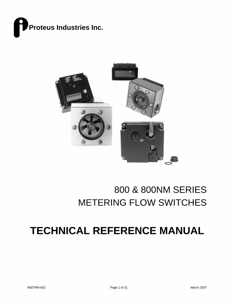
• Compact design Depth depends on connection size and type
Figure 1: Outline of 800 Series
800TRM-002 Page 3 of 21 March 2007
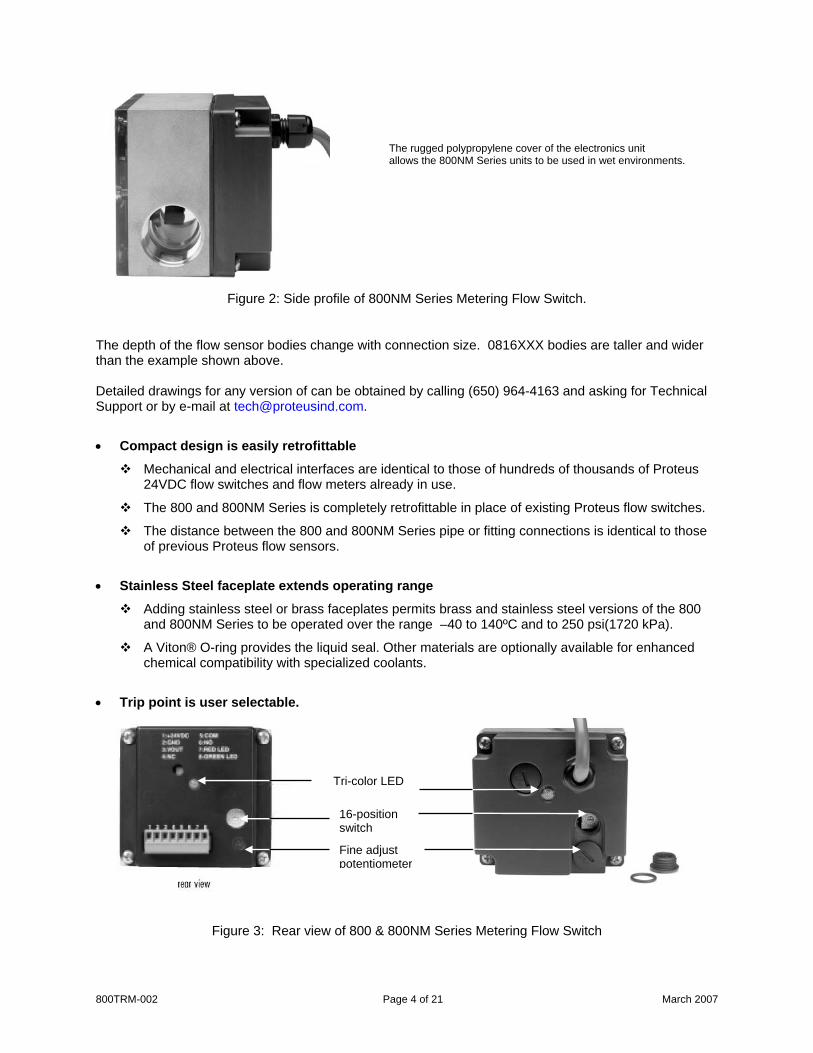
The rugged polypropylene cover of the electronics unit
allows the 800NM Series units to be used in wet environments.
Figure 2: Side profile of 800NM Series Metering Flow Switch.
The depth of the flow sensor bodies change with connection size. 0816XXX bodies are taller and wider than the example shown above. Detailed drawings for any version of can be obtained by calling (650) 964-4163 and asking for Technical Support or by e-mail at [email protected].
• Compact design is easily retrofittable
Mechanical and electrical interfaces are identical to those of hundreds of thousands of Proteus 24VDC flow switches and flow meters already in use.
The 800 and 800NM Series is completely retrofittable in place of existing Proteus flow switches.
The distance between the 800 and 800NM Series pipe or fitting connections is identical to those of previous Proteus flow sensors.
• Stainless Steel faceplate extends operating range
Adding stainless steel or brass faceplates permits brass and stainless steel versions of the 800 and 800NM Series to be operated over the range –40 to 140ºC and to 250 psi(1720 kPa).
A Viton® O-ring provides the liquid seal. Other materials are optionally available for enhanced chemical compatibility with specialized coolants.
• Trip point is user selectable.
800TRM-002 Page 4 of 21 March 2007
Tri-color LED
16-position switch
Figure 3: Rear view of 800 & 800NM Series Metering Flow Switch
Fine adjust potentiometer
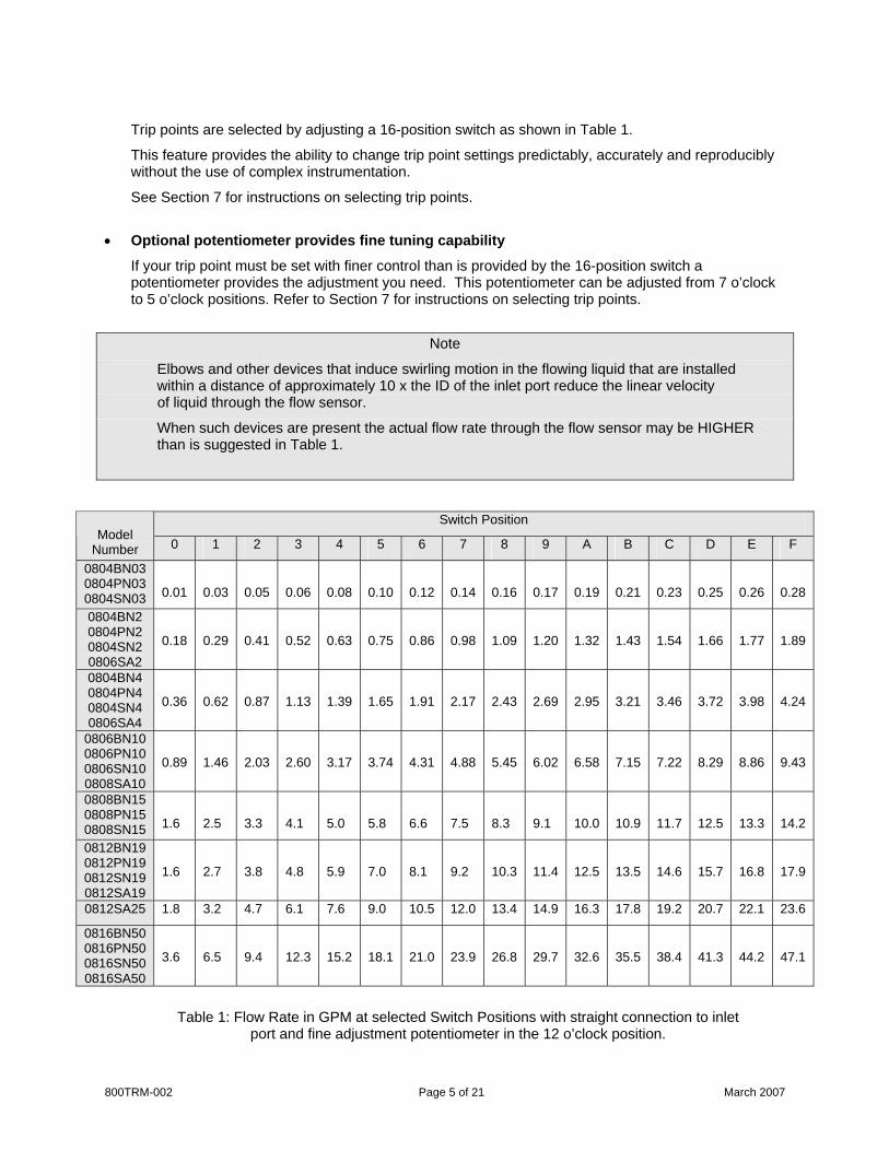
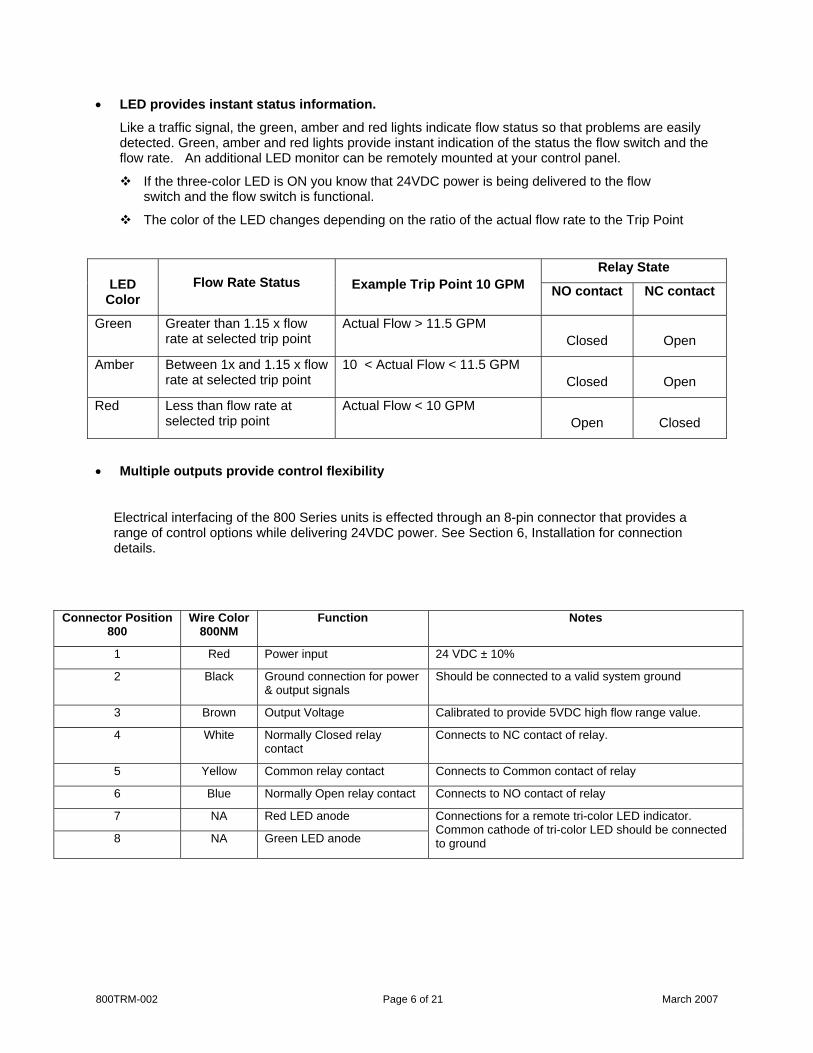
Trip points are selected by adjusting a 16-position switch as shown in Table 1.
This feature provides the ability to change trip point settings predictably, accurately and reproducibly without the use of complex instrumentation.
See Section 7 for instructions on selecting trip points.
• Optional potentiometer provides fine tuning capability
If your trip point must be set with finer control than is provided by the 16-position switch a potentiometer provides the adjustment you need. This potentiometer can be adjusted from 7 o’clock to 5 o’clock positions. Refer to Section 7 for instructions on selecting trip points.
Note
Elbows and other devices that induce swirling motion in the flowing liquid that are installed within a distance of approximately 10 x the ID of the inlet port reduce the linear velocity of liquid through the flow sensor.
When such devices are present the actual flow rate through the flow sensor may be HIGHER than is suggested in Table 1.
Switch Position Model
Number 0 1 2 3 4 5 6 7 8 9 A B C D E F
0804BN03 0804PN03 0804SN03
0.01
0.03
0.05
0.06
0.08
0.10
0.12
0.14
0.16
0.17
0.19
0.21
0.23
0.25
0.26
0.28
0804BN2 0804PN2 0804SN2 0806SA2
0.18
0.29
0.41
0.52
0.63
0.75
0.86
0.98
1.09
1.20
1.32
1.43
1.54
1.66
1.77
1.89
0804BN4 0804PN4 0804SN4 0806SA4
0.36
0.62
0.87
1.13
1.39
1.65
1.91
2.17
2.43
2.69
2.95
3.21
3.46
3.72
3.98
4.24
0806BN10 0806PN10 0806SN10 0808SA10
0.89
1.46
2.03
2.60
3.17
3.74
4.31
4.88
5.45
6.02
6.58
7.15
7.22
8.29
8.86
9.43
0808BN15 0808PN15 0808SN15
1.6
2.5
3.3
4.1
5.0
5.8
6.6
7.5
8.3
9.1
10.0
10.9
11.7
12.5
13.3
14.2
0812BN19 0812PN19 0812SN19 0812SA19
1.6
2.7
3.8
4.8
5.9
7.0
8.1
9.2
10.3
11.4
12.5
13.5
14.6
15.7
16.8
17.9
0812SA25 1.8 3.2 4.7 6.1 7.6 9.0 10.5 12.0 13.4 14.9 16.3 17.8 19.2 20.7 22.1 23.6
0816BN50 0816PN50 0816SN50 0816SA50
3.6
6.5
9.4
12.3
15.2
18.1
21.0
23.9
26.8
29.7
32.6
35.5
38.4
41.3
44.2
47.1
Table 1: Flow Rate in GPM at selected Switch Positions with straight connection to inlet port and fine adjustment potentiometer in the 12 o’clock position.
800TRM-002 Page 5 of 21 March 2007
800TRM-002 Page 6 of 21 March 2007
• LED provides instant status information.
Like a traffic signal, the green, amber and red lights indicate flow status so that problems are easily detected. Green, amber and red lights provide instant indication of the status the flow switch and the flow rate. An additional LED monitor can be remotely mounted at your control panel.
If the three-color LED is ON you know that 24VDC power is being delivered to the flow switch and the flow switch is functional.
The color of the LED changes depending on the ratio of the actual flow rate to the Trip Point
Relay State
LED Color
Flow Rate Status
Example Trip Point 10 GPM NO contact NC contact
Green Greater than 1.15 x flow rate at selected trip point
Actual Flow > 11.5 GPM
Closed
Open
Amber Between 1x and 1.15 x flow rate at selected trip point
10 < Actual Flow < 11.5 GPM
Closed
Open
Red Less than flow rate at selected trip point
Actual Flow < 10 GPM
Open
Closed
• Multiple outputs provide control flexibility
Electrical interfacing of the 800 Series units is effected through an 8-pin connector that provides a range of control options while delivering 24VDC power. See Section 6, Installation for connection details.
Connector Position 800
Wire Color 800NM
Function Notes
1 Red Power input 24 VDC ± 10%
2 Black Ground connection for power & output signals
Should be connected to a valid system ground
3 Brown Output Voltage Calibrated to provide 5VDC high flow range value.
4 White Normally Closed relay contact
Connects to NC contact of relay.
5 Yellow Common relay contact Connects to Common contact of relay
6 Blue Normally Open relay contact Connects to NO contact of relay
7 NA Red LED anode
8 NA Green LED anode
Connections for a remote tri-color LED indicator. Common cathode of tri-color LED should be connected to ground
800TRM-002 Page 7 of 21 March 2007
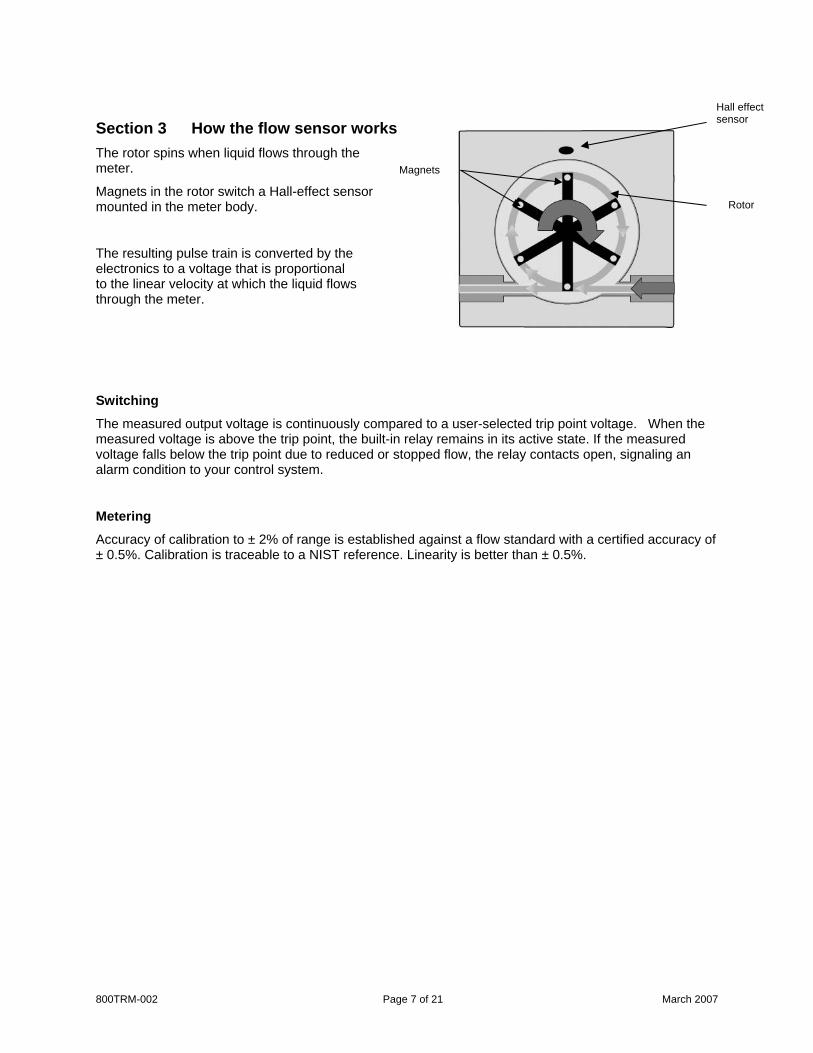
Section 3 How the flow sensor works The rotor spins when liquid flows through the meter.
Magnets in the rotor switch a Hall-effect sensor mounted in the meter body.
The resulting pulse train is converted by the electronics to a voltage that is proportional to the linear velocity at which the liquid flows through the meter.
Hall effect sensor
Magnets
Rotor
Switching
The measured output voltage is continuously compared to a user-selected trip point voltage. When the measured voltage is above the trip point, the built-in relay remains in its active state. If the measured voltage falls below the trip point due to reduced or stopped flow, the relay contacts open, signaling an alarm condition to your control system.
Metering
Accuracy of calibration to ± 2% of range is established against a flow standard with a certified accuracy of ± 0.5%. Calibration is traceable to a NIST reference. Linearity is better than ± 0.5%.
800TRM-002 Page 8 of 21 March 2007
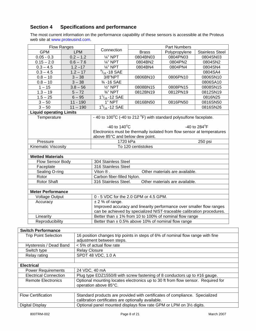
Section 4 Specifications and performance The most current information on the performance capability of these sensors is accessible at the Proteus web site at www.proteusind.com.
Flow Ranges Part Numbers GPM LPM
Connection Brass Polypropylene Stainless Steel 0.05 - 0.3 0.2 – 1.2 ¼” NPT 0804BN03 0804PN03 0804SN03 0.15 – 2.0 0.6 – 7.6 ¼” NPT 0804BN2 0804PN2 0804SN2 0.3 – 4.5 1.2 –17 ¼” NPT 0804BN4 0804PN4 0804SN4 0.3 – 4.5 1.2 – 17 9/16 -18 SAE 0804SA4 0.8 – 10 3 – 38 3/8”NPT 0806BN10 0806PN10 0806SN10 0.8 – 10 3 – 38 ¾ -16 SAE 0806SA10 1 – 15 3.8 – 56 ½” NPT 0808BN15 0808PN15 0808SN15
1.3 – 19 5 – 72 ¾” NPT 0812BN19 0812PN19 0812SN19 1.5 – 25 6 – 95 11/16 -12 SAE 0816N25 3 – 50 11 - 190 1” NPT 0816BN50 0816PN50 0816SN50 3 – 50 11 – 190 15/16 -12 SAE 0816SN26
Liquid operating Limits Temperature - 40 to 100oC (-40 to 212 oF) with standard polysulfone faceplate.
-40 to 140oC -40 to 284oF Electronics must be thermally isolated from flow sensor at temperatures above 85°C and below dew point.
Pressure 1720 kPa 250 psi Kinematic Viscosity To 120 centistokes Wetted Materials Flow Sensor Body 304 Stainless Steel Faceplate 316 Stainless Steel Sealing O-ring Viton ® . Other materials are available. Rotor Carbon fiber-filled Nylon. Rotor Shaft 316 Stainless Steel. Other materials are available. Meter Performance Voltage Output 0 - 5 VDC for the 2.0 GPM or 4.5 GPM. Accuracy ± 2 % of range.
Improved accuracy and linearity performance over smaller flow ranges can be achieved by specialized NIST-traceable calibration procedures.
Linearity Better than ± 1% from 10 to 100% of nominal flow range Reproducibility Better than ± 0.5% above 10% of nominal flow range
Switch Performance Trip Point Selection 16 position changes trip points in steps of 6% of nominal flow range with fine
adjustment between steps. Hysteresis / Dead Band < 5% of actual flow rate Switch type Relay Closure Relay rating SPDT 48 VDC, 1.0 A Electrical Power Requirements 24 VDC, 40 mA Electrical Connection Plug type EDZ1550/8 with screw fastening of 8 conductors up to #16 gauge. Remote Electronics Optional mounting locates electronics up to 30 ft from flow sensor. Required for
operation above 85°C. Flow Certification Standard products are provided with certificates of compliance. Specialized
calibration certificates are optionally available. Digital Display Optional panel mounted displays flow rate GPM or LPM on 3½ digits.

Section 5 Product certifications 800 and 800NM Series Metering Flow Switches are CE marked for compliance with the EU Directive 89/336/EEC for Electromagnetic Compatibility. 800 and 800NM Series Metering Flow Switches have been Safety Certified by RWTUV as a low voltage, Class III device. Section 6 Installation
CAUTION!
It is generally undesirable to mount any plumbing connections directly over electronic controls or instruments.
WARNING!
If the 800 Series flow sensor is mounted in a vertical pipeline, any leakage from the topmost
connection could enter the unit and cause permanent damage to the electronics.
In applications where there is condensation, moisture, dampness or dripping water the 800NM Series should be used.
Pipe or tubing mounting If rigid piping or tubing is used, the 800 and 800NM Series metering flow switch may be supported by direct connection to the pipe or tubing. Panel mounting To mount the sensor behind a panel, two of the faceplate securing screws will need to be replaced with longer screws to compensate for the thickness of the panel. Ensure that the screws are not so long that they will touch the bottom of the tapped hole, or rip through the back of a plastic body if over-tightened. Evenly space up to six holes for 8-32 screws on a 2.5” circle. Using the two holes on the horizontal plane is usually sufficient to support smaller flow sensors and all plastic sensors. If you wish the rotor to be visible, cut a 1¾” diameter hole with the same center.
1. Remove screws holding the faceplate to
the sensor body. 2. Place the sensor behind the panel and
insert the longer screws you have selected.
3. Secure the screws in the body with a torque of ~ 10 in-lb. (Finger tight with a flat-blade screwdriver.).
Figure 3: Layout for panel mounting 800TRM-002 Page 9 of 21 March 2007
800TRM-002 Page 10 of 21 March 2007
Note
Dimensioned drawings illustrating the 800 and 800NM Series Metering Flow Switches are available as
PDF files on our web site at www.proteusind.com.
Plumbing Connections
Note Before connecting a sensor into your fluid line, verify that the normal flow rates expected in that line are within the operating range of the sensor. Extended use above the rated maximum flow rate of the sensor will reduce its useable life.
CAUTION
Do NOT use anaerobic pipe sealants such as LOCTITE brand sealants or SWAK with the 800 and 800NM Series metering flow switches fitted with a clear polysulfone faceplate.
The aggressive chemical nature of these materials can cause cracking of the polysulfone faceplate.
Use Teflon (PTFE) tape or PTFE-based liquid sealants to provide leak-tight and lubricated junctions at all connection points. Real-Tuff and Hercules are two of many suitable brands of PTFE-based sealants.
Note
It is recommended that connections to the stainless steel flow sensor be made with stainless steel or materials of similarly chemical inertness to minimize potential corrosion damage.
Note
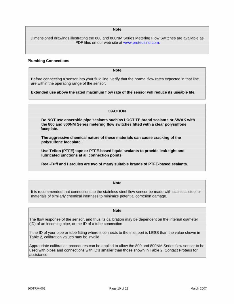
The flow response of the sensor, and thus its calibration may be dependent on the internal diameter (ID) of an incoming pipe, or the ID of a tube connection. If the ID of your pipe or tube fitting where it connects to the inlet port is LESS than the value shown in Table 2, calibration values may be invalid. Appropriate calibration procedures can be applied to allow the 800 and 800NM Series flow sensor to be used with pipes and connections with ID’s smaller than those shown in Table 2. Contact Proteus for assistance.
800TRM-002 Page 11 of 21 March 2007
Model # Flow Range
GPM Flow Range
LPM Orifice ID
inches Orifice ID
mm 080XN03 0.05 – 0.3 0.2 – 1.2 0.063 0804XN2 0804SA2
0.1 – 2.0 0.6 – 7.5 0.188 4.8
0804XN4 0804SA4
0.3 – 4.5 1.2 – 17.0 0.270 6.9
0806XN10 0.8 – 10 3 – 38 0.370 9.4 0806SA10 0.8 – 10 3 – 38 0.400 10.1 0808XN15 1 – 15 3.8 - 56 0.460 11.7 0812XN19 0812SA19
1.3 – 19 5 – 72 0.610 15.5
0812SA25 1.5 – 25 6 - 95 0.610 15.5 0816XN50 0816SA50
3 – 50 11 – 190 0.870 22.1
Table 2: Minimum ID of pipe or connection for calibrations to be valid.
Note The flow response of 800 and 800NM Series sensors and thus their calibration may be dependent on the form of the device attached to the inlet connection and other closely located up-stream devices. Elbows, T-pieces, valves and filters located immediately up-stream from the flow sensor can introduce swirling motion to the liquid flow. The swirling motion reduces the linear velocity of the flow stream. We recommend that a straight run of pipe of more than 10 x pipe ID be used between the flow sensor and any up-stream devices to minimize these effects. Appropriate calibration procedures must be used to provide an accurate flow measurement with elbows or T-pieces that must be attached directly to the inlet connection. The 800 and 800NM Series sensor is typically unaffected by the form or proximity of devices on its downstream side. Sensor Orientation For the best results, 800 and 800NM Series sensors should be mounted with the faceplate in the vertical plane. Mounting the device with the flow connections uppermost can help eliminate entrained air from your system. Flow Direction The 800 and 800NM Series Metering Flow Switch is not sensitive to flow direction. Flow can be introduced to the sensor from either side. NPT pipe thread connections Pipe threads seal by making metal-to-metal contact between male and female components. Consequently they are particularly prone to the damaging effects of galling, which occurs when two surfaces move against each other under pressure. When installing pipe threads it is essential to use a high quality lubricating and sealing material.

• Use Teflon tape or a PTFE-based liquid sealant to provide lubrication for the junction and a leak-tight connection at both input and output connections. Real-Tuff and Hercules are two of many suitable brands of PTFE-based sealants.
• Do not over-tighten the connection. Refer to instructions for installation of the mating fittings for information on torque requirements.
• Leak testing of all connections in your flow circuit is recommended. Pressurizing the system with air and external testing with a dilute soap solution can help identify leaking connections.
SAE straight thread connections With these connectors, an O-ring makes the seal while the threads hold the connecting assembly in place. Straight thread connections should receive a small amount of high-pressure lubricant before installation to prevent galling. Non-adjustable fittings
1. Bring the non-adjustable fitting into firm contact with the face of the port, using a wrench.
800TRM-002 Page 12 of 21 March 2007
2. Check to be certain that the O-ring fits easily into the non-threaded receiving area of the port, and is not pinched.
Adjustable fittings
1. Ensure that the locknut is positioned so the back-up washer is in contact with the beginning of the threads farthest from the end of the fitting.
2. Screw the fitting into the port until the back-up washer contacts the sealing face.
3. Check to be certain that the O-ring fits easily into the non-threaded receiving area of the port, and is not pinched or damaged.
4. Unscrew the fitting a maximum of one turn to position it in the desired direction.
5. Tighten the locknut firmly against the back-up washer so the fitting assembly is held securely in place.
Filtering Your circulating fluid may contain particles. While not essential to the operation of the flow sensor, it is good practice to filter your fluid. A 100-micron filter is often used to remove rust and other particles from the fluid. This can increase the lifetime of pumps and other fluid system components as well as reducing wear in the sensor.
Fluid Temperature Range & Remote Mounting Electronics If fluid temperatures will be outside the range of 0 - 85°C, the electronics package must be mounted remotely from the sensor. Remote mounting requires customized changes to the sensors. Please contact Proteus Applications for additional information. Electrical Connections
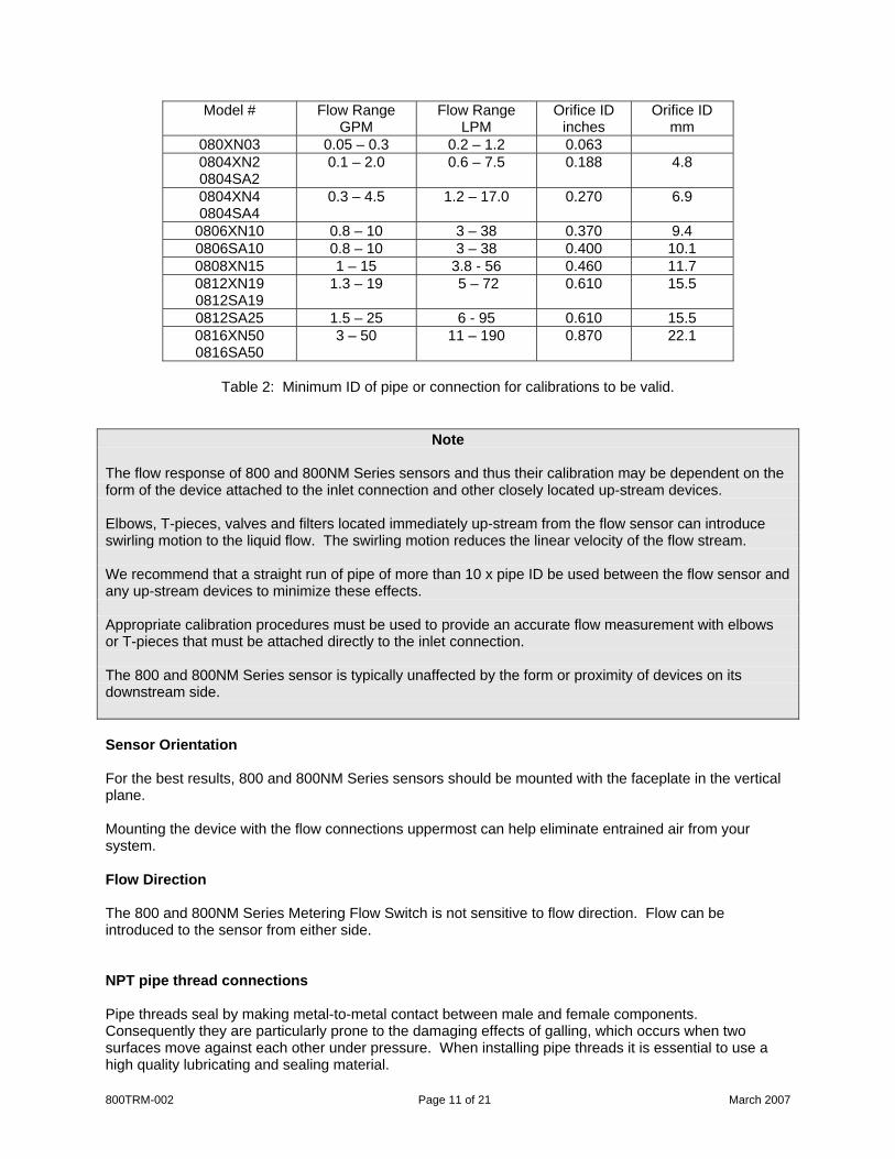
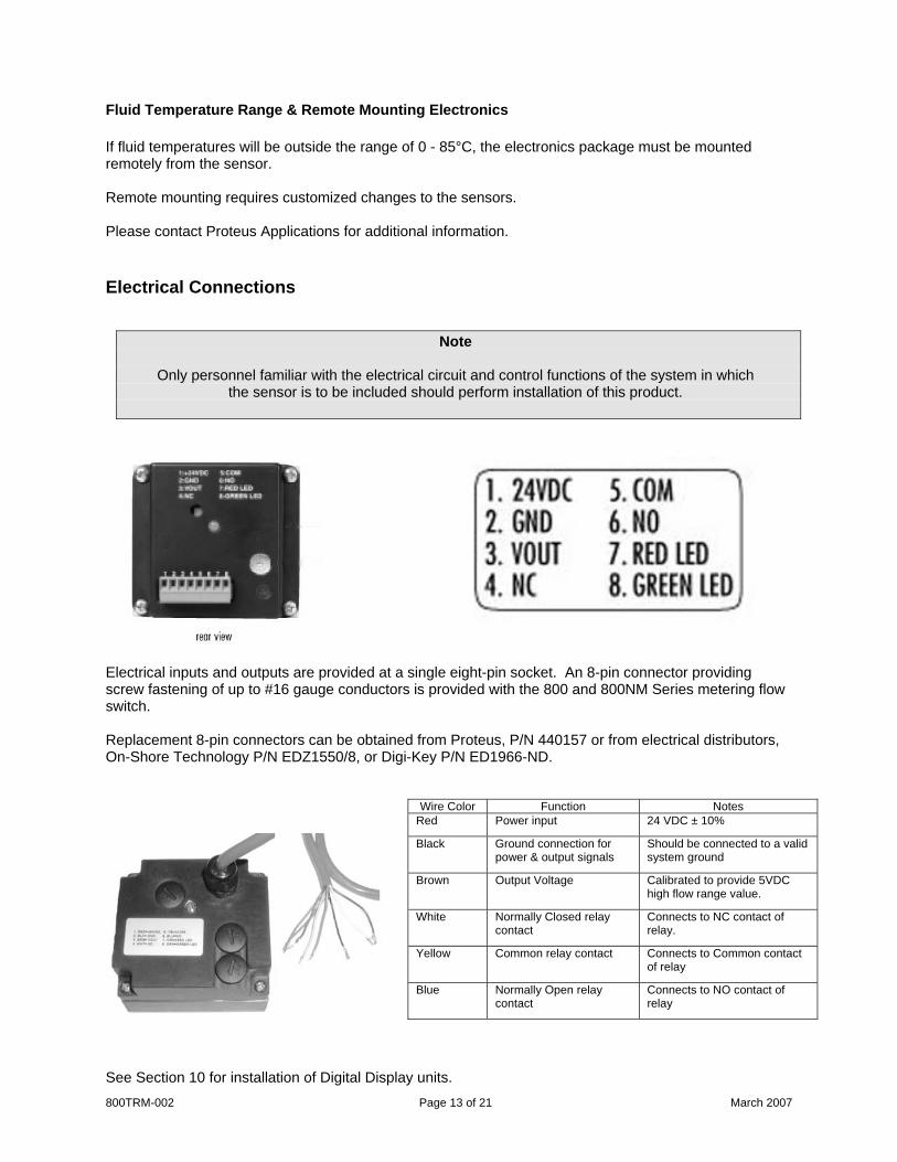
Note
Only personnel familiar with the electrical circuit and control functions of the system in which
the sensor is to be included should perform installation of this product.
Electrical inputs and outputs are provided at a single eight-pin socket. An 8-pin connector providing screw fastening of up to #16 gauge conductors is provided with the 800 and 800NM Series metering flow switch. Replacement 8-pin connectors can be obtained from Proteus, P/N 440157 or from electrical distributors, On-Shore Technology P/N EDZ1550/8, or Digi-Key P/N ED1966-ND.
800TRM-002 Page 13 of 21 March 2007
Wire Color Function Notes Red Power input 24 VDC ± 10%
Black Ground connection for power & output signals
Should be connected to a valid system ground
Brown Output Voltage Calibrated to provide 5VDC high flow range value.
White Normally Closed relay contact
Connects to NC contact of relay.
Yellow Common relay contact Connects to Common contact of relay
Blue Normally Open relay contact
Connects to NO contact of relay
See Section 10 for installation of Digital Display units.
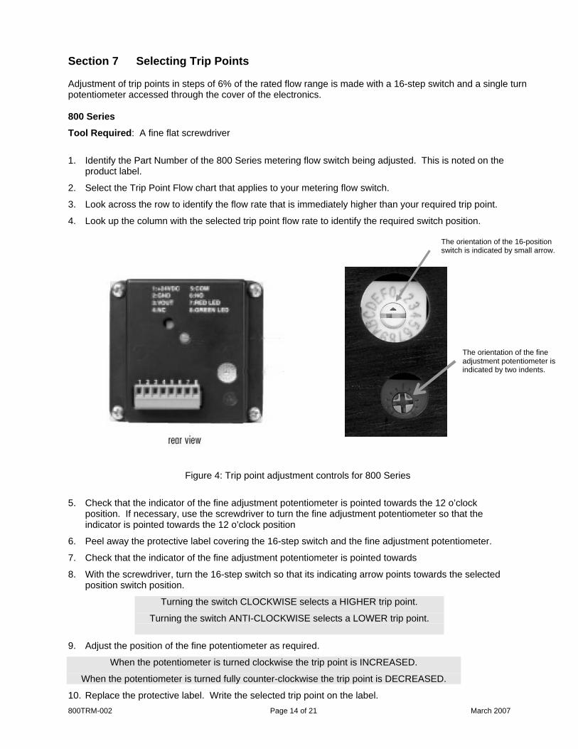
Section 7 Selecting Trip Points Adjustment of trip points in steps of 6% of the rated flow range is made with a 16-step switch and a single turn potentiometer accessed through the cover of the electronics. 800 Series
Tool Required: A fine flat screwdriver
1. Identify the Part Number of the 800 Series metering flow switch being adjusted. This is noted on the product label.
2. Select the Trip Point Flow chart that applies to your metering flow switch.
3. Look across the row to identify the flow rate that is immediately higher than your required trip point.
4. Look up the column with the selected trip point flow rate to identify the required switch position. The orientation of the 16-position
switch is indicated by small arrow.
800TRM-002 Page 14 of 21 March 2007
The orientation of the fine adjustment potentiometer is indicated by two indents.
Figure 4: Trip point adjustment controls for 800 Series
5. Check that the indicator of the fine adjustment potentiometer is pointed towards the 12 o’clock position. If necessary, use the screwdriver to turn the fine adjustment potentiometer so that the indicator is pointed towards the 12 o’clock position
6. Peel away the protective label covering the 16-step switch and the fine adjustment potentiometer.
7. Check that the indicator of the fine adjustment potentiometer is pointed towards
8. With the screwdriver, turn the 16-step switch so that its indicating arrow points towards the selected position switch position.
Turning the switch CLOCKWISE selects a HIGHER trip point.
Turning the switch ANTI-CLOCKWISE selects a LOWER trip point.
9. Adjust the position of the fine potentiometer as required.
When the potentiometer is turned clockwise the trip point is INCREASED.
When the potentiometer is turned fully counter-clockwise the trip point is DECREASED.
10. Replace the protective label. Write the selected trip point on the label.
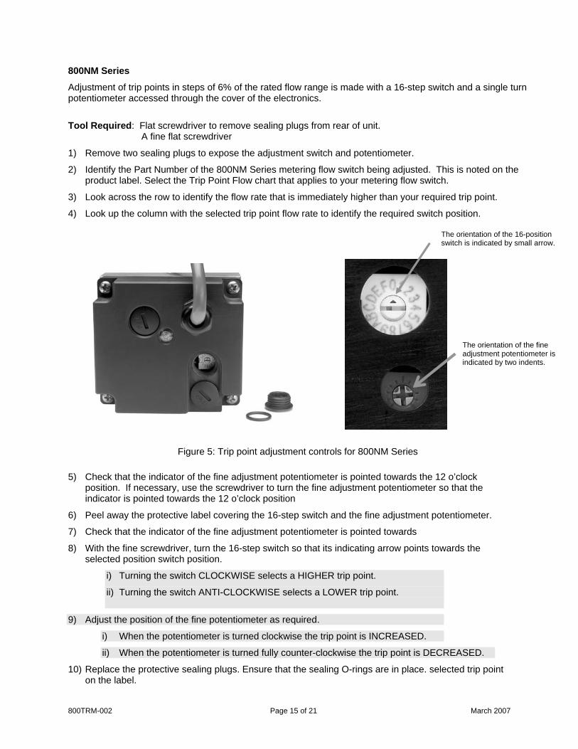
800NM Series
Adjustment of trip points in steps of 6% of the rated flow range is made with a 16-step switch and a single turn potentiometer accessed through the cover of the electronics.
Tool Required: Flat screwdriver to remove sealing plugs from rear of unit. A fine flat screwdriver
1) Remove two sealing plugs to expose the adjustment switch and potentiometer.
2) Identify the Part Number of the 800NM Series metering flow switch being adjusted. This is noted on the product label. Select the Trip Point Flow chart that applies to your metering flow switch.
3) Look across the row to identify the flow rate that is immediately higher than your required trip point.
4) Look up the column with the selected trip point flow rate to identify the required switch position. The orientation of the 16-position
switch is indicated by small arrow.
800TRM-002 Page 15 of 21 March 2007
The orientation of the fine adjustment potentiometer is indicated by two indents.
Figure 5: Trip point adjustment controls for 800NM Series
5) Check that the indicator of the fine adjustment potentiometer is pointed towards the 12 o’clock position. If necessary, use the screwdriver to turn the fine adjustment potentiometer so that the indicator is pointed towards the 12 o’clock position
6) Peel away the protective label covering the 16-step switch and the fine adjustment potentiometer.
7) Check that the indicator of the fine adjustment potentiometer is pointed towards
8) With the fine screwdriver, turn the 16-step switch so that its indicating arrow points towards the selected position switch position.
i) Turning the switch CLOCKWISE selects a HIGHER trip point.
ii) Turning the switch ANTI-CLOCKWISE selects a LOWER trip point.
9) Adjust the position of the fine potentiometer as required.
i) When the potentiometer is turned clockwise the trip point is INCREASED.
ii) When the potentiometer is turned fully counter-clockwise the trip point is DECREASED.
10) Replace the protective sealing plugs. Ensure that the sealing O-rings are in place. selected trip point on the label.
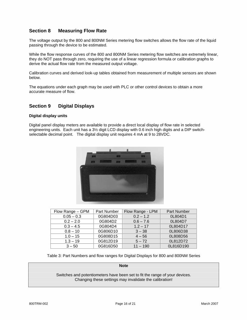
Section 8 Measuring Flow Rate The voltage output by the 800 and 800NM Series metering flow switches allows the flow rate of the liquid passing through the device to be estimated. While the flow response curves of the 800 and 800NM Series metering flow switches are extremely linear, they do NOT pass through zero, requiring the use of a linear regression formula or calibration graphs to derive the actual flow rate from the measured output voltage. Calibration curves and derived look-up tables obtained from measurement of multiple sensors are shown below. The equations under each graph may be used with PLC or other control devices to obtain a more accurate measure of flow. Section 9 Digital Displays Digital display units Digital panel display meters are available to provide a direct local display of flow rate in selected engineering units. Each unit has a 3½ digit LCD display with 0.6 inch high digits and a DIP switch-selectable decimal point. The digital display unit requires 4 mA at 9 to 28VDC.
Flow Range – GPM Part Number Flow Range - LPM Part Number
0.05 – 0.3 0G804D03 0.2 – 1.2 0L804D1 0.2 – 2.0 0G804D2 0.6 – 7.6 0L804D7 0.3 – 4.5 0G804D4 1.2 – 17 0L804D17 0.8 – 10 0G806D10 3 – 38 0L806D38 1.0 – 15 0G808D15 4 – 56 0L808D56 1.3 – 19 0G812D19 5 – 72 0L812D72 3 – 50 0G816D50 11 – 190 0L816D190
Table 3: Part Numbers and flow ranges for Digital Displays for 800 and 800NM Series
Note
Switches and potentiometers have been set to fit the range of your devices.
Changing these settings may invalidate the calibration!
800TRM-002 Page 16 of 21 March 2007
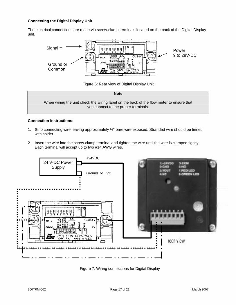
Connecting the Digital Display Unit The electrical connections are made via screw-clamp terminals located on the back of the Digital Display unit.
Signal +
800TRM-002 Page 17 of 21 March 2007
Figure 6: Rear view of Digital Display Unit
Note
When wiring the unit check the wiring label on the back of the flow meter to ensure that
you connect to the proper terminals.
Connection instructions: 1. Strip connecting wire leaving approximately ¼” bare wire exposed. Stranded wire should be tinned
with solder.
2. Insert the wire into the screw-clamp terminal and tighten the wire until the wire is clamped tightly. Each terminal will accept up to two #14 AWG wires.
24 V-DC Power Supply
Power 9 to 28V-DC
Ground or Common
+24VDC
Ground or -ve
Figure 7: Wiring connections for Digital Display

Section 10 Cleaning and Maintenance Maintenance of the 800 and 800NM Series Metering flow switch is normally limited to cleaning the chamber in which the rotor spins and an annual recalibration. Cleaning the 800 and 800NM Series flow sensor The frequency of cleaning will vary with the type and cleanliness of the liquid being run through the flow meter. In most cases, annual cleaning immediately prior to recalibration is sufficient. Tools required: Wrenches to disconnect the flow meter from your flow circuit. A flat screw driver. Soft cleaning cloth Alcohol, water or a dilute detergent solution.
Cleaning the 800 and 800NM Series Flow Sensor 1. Turn OFF the liquid flow in your flow circuit
and remove the 800 and 800NM Series sensor from your system. Place the sensor on a clean surface.
2. Remove the 6 screws securing the faceplate.
3. Remove the faceplate from the flow meter.
800TRM-002 Page 18 of 21 March 2007
Cleaning the 800 and 800NM Series Flow Sensor
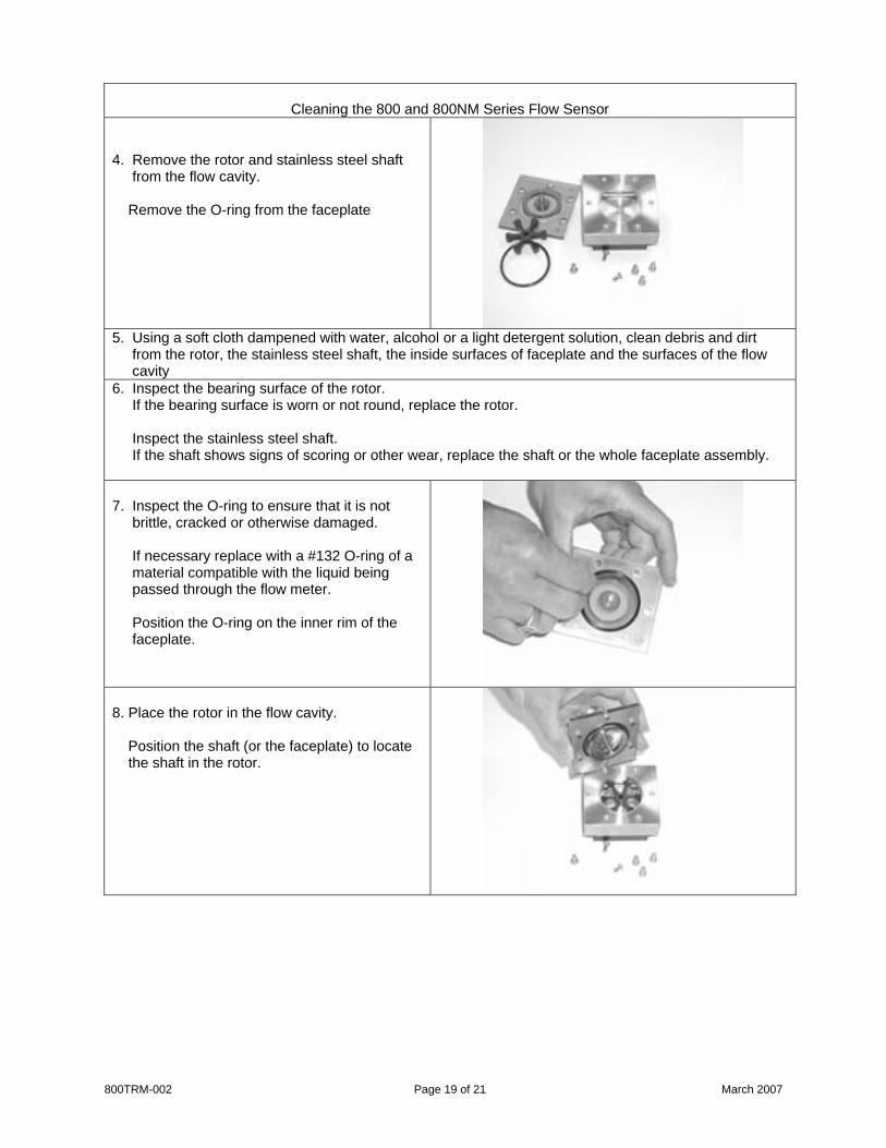
4. Remove the rotor and stainless steel shaft from the flow cavity. Remove the O-ring from the faceplate
5. Using a soft cloth dampened with water, alcohol or a light detergent solution, clean debris and dirt from the rotor, the stainless steel shaft, the inside surfaces of faceplate and the surfaces of the flow cavity 6. Inspect the bearing surface of the rotor. If the bearing surface is worn or not round, replace the rotor. Inspect the stainless steel shaft. If the shaft shows signs of scoring or other wear, replace the shaft or the whole faceplate assembly. 7. Inspect the O-ring to ensure that it is not brittle, cracked or otherwise damaged. If necessary replace with a #132 O-ring of a material compatible with the liquid being passed through the flow meter. Position the O-ring on the inner rim of the faceplate.
8. Place the rotor in the flow cavity. Position the shaft (or the faceplate) to locate the shaft in the rotor.
800TRM-002 Page 19 of 21 March 2007
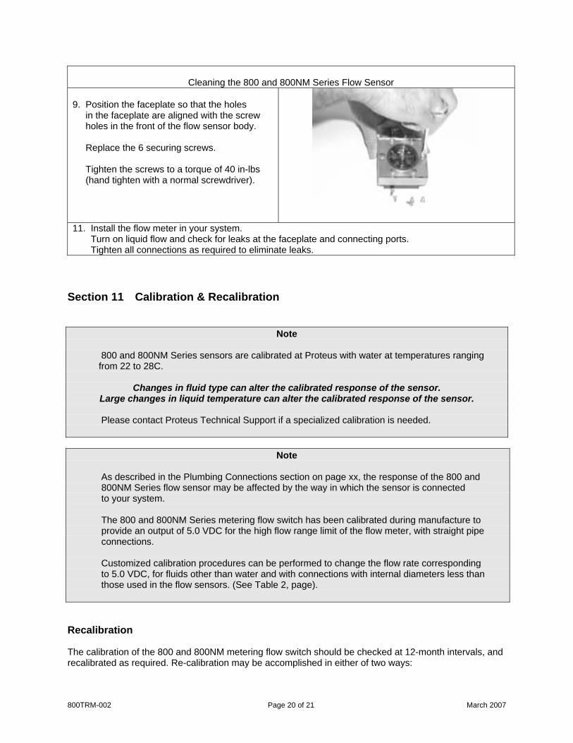
Cleaning the 800 and 800NM Series Flow Sensor 9. Position the faceplate so that the holes in the faceplate are aligned with the screw holes in the front of the flow sensor body. Replace the 6 securing screws. Tighten the screws to a torque of 40 in-lbs (hand tighten with a normal screwdriver).
11. Install the flow meter in your system. Turn on liquid flow and check for leaks at the faceplate and connecting ports. Tighten all connections as required to eliminate leaks.
Section 11 Calibration & Recalibration
Note
800 and 800NM Series sensors are calibrated at Proteus with water at temperatures ranging from 22 to 28C.
Changes in fluid type can alter the calibrated response of the sensor. Large changes in liquid temperature can alter the calibrated response of the sensor.
Please contact Proteus Technical Support if a specialized calibration is needed.
Note
As described in the Plumbing Connections section on page xx, the response of the 800 and 800NM Series flow sensor may be affected by the way in which the sensor is connected to your system.
The 800 and 800NM Series metering flow switch has been calibrated during manufacture to provide an output of 5.0 VDC for the high flow range limit of the flow meter, with straight pipe connections.
Customized calibration procedures can be performed to change the flow rate corresponding to 5.0 VDC, for fluids other than water and with connections with internal diameters less than those used in the flow sensors. (See Table 2, page).
Recalibration The calibration of the 800 and 800NM metering flow switch should be checked at 12-month intervals, and recalibrated as required. Re-calibration may be accomplished in either of two ways:
800TRM-002 Page 20 of 21 March 2007
800TRM-002 Page 21 of 21 March 2007
Calibration by Proteus To obtain a price quotation and a Return Material Authorization number for recalibration of your flow meter, contact [email protected] or call (650) 964-4163.
When received at Proteus, your flow meter will:
1. Have its output measured and recorded in the as-received state. 2. The rotor, stainless steel shaft and sealing O-ring will be replaced. 3. The flow cavity will be cleaned and the device reassembled.. 4. The unit will be recalibrated to its original specification against reference standards whose
calibrations are statistically controlled against NIST-traceable standards. 5. A new calibration certificate will be issued. 6. A new calibration label will be attached to the flow meter.
Direct calibration against NIST-traceable standards is optionally available.
Calibration by another laboratory. The calibrating laboratory will issue certificates and labels identifying the calibration status of your metering flow switch.
Please advise your selected calibration laboratory to contact Proteus for calibration instructions. Nylon, Real-Tuff and Hercules are trademarks of their respective holders 800 and 800NM Series electronics are sensitive to Electro Static Discharge. There is normally no need to open the electronics case, but if it is opened, proper ESD precautions should be taken. Information in this document was correct at the time of printing; however, specifications are subject to alteration as Proteus Industries’ continuous improvement processes establish new capabilities.