Embed Size (px)
Citation preview
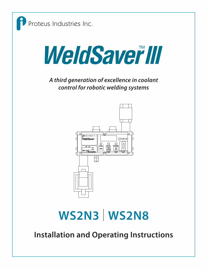
A third generation of excellence in coolant control for robotic welding systems
WS2N3 WS2N8Installation and Operating Instructions
Proteus Industries Inc.
�
Technical Support
Proteus Industries Inc.340 Pioneer WayMountain View, CA 94041Tel: (650) 964-4163Fax: (650) 965-0304E-mail: [email protected]
In the Detroit, MI area, local support is available from:
MJM Sales, Inc.2660 Auburn Road, Suite 300Auburn Hills, MI 48326Tel: (248) 299-0525Fax: (248) 299-0528
Table of Contents
Section Description Page
1 Contacts & Cautions 3
2 What It Is & What It Does 4
3 How It Works 6
4 Installation & Testing 7
4.1 Mechanical Installation & Water Connections 7
4.2 Electrical & DeviceNet® Connections 10
4.3 Three Functionality Tests 12
5 Selecting Control Parameter Values 14
6 Troubleshooting 17
6.1 Status Faults 17
6.2 Operating Faults 18
6.3 WeldSaver Faults 20
7 Dimensional Drawings 23
WS2NUM Rev 004 04/2008
Information in this document was correct at the time of printing; however, specifications are subject to change as Proteus Industries’ continuous improvement processes establish new capabilities.
© Proteus Industries Inc.
Proteus Industries Inc.340 Pioneer Way, Mountain View, CA 94041Tel: (650) 964-4163 Fax: (650) 965-0304www.proteusind.com [email protected]
�
Section 1 : Contacts & Cautions
NOTEProduct warranty does NOT cover the repair of installation errors.
Proteus WeldSavers are manufactured by ISO 9001 registered processes and are warranted to be free from defects in material and workmanship for 2 years from the date of shipment. The full text of this limited warranty is accessible on the Proteus Industries website at www.proteusind.com/warranty/.
The cost of cleaning flow sensors, recalibration or repair of mechanical damage in-curred during installation of the product are NOT covered by the warranty.
A Purchase Order will be required to allow recovery of such service costs.
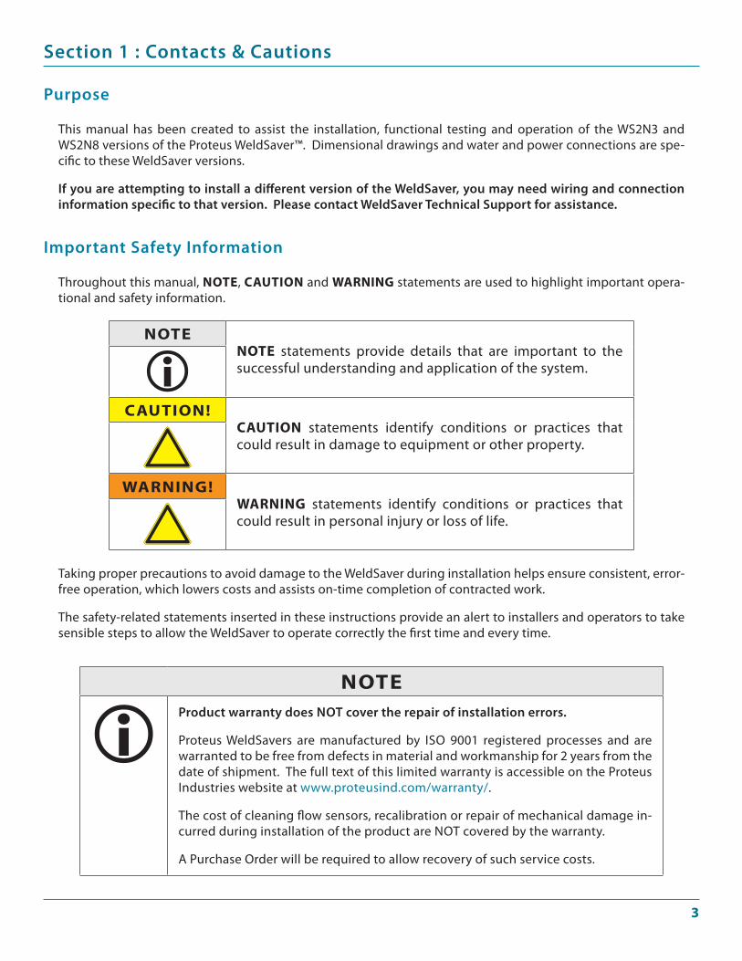
Throughout this manual, NOTE, CAUTION and wArNINg statements are used to highlight important opera-tional and safety information.
Important Safety Information
Taking proper precautions to avoid damage to the WeldSaver during installation helps ensure consistent, error-free operation, which lowers costs and assists on-time completion of contracted work.
The safety-related statements inserted in these instructions provide an alert to installers and operators to take sensible steps to allow the WeldSaver to operate correctly the first time and every time.
NOTENOTE statements provide details that are important to the successful understanding and application of the system.
CAUTION!CAUTION statements identify conditions or practices that could result in damage to equipment or other property.
wArNINg!wArNINg statements identify conditions or practices that could result in personal injury or loss of life.
This manual has been created to assist the installation, functional testing and operation of the WS2N3 and WS2N8 versions of the Proteus WeldSaver™. Dimensional drawings and water and power connections are spe-cific to these WeldSaver versions.
If you are attempting to install a different version of the WeldSaver, you may need wiring and connection information specific to that version. Please contact WeldSaver Technical Support for assistance.
Purpose
�
Section 2 : What It Is & What It Does
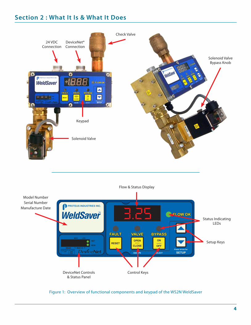
Figure 1: Overview of functional components and keypad of the WS2N WeldSaver
Flow & Status Display
Status Indicating LEDs
Setup Keys
Control KeysDeviceNet Controls & Status Panel
Model NumberSerial Number
Manufacture Date
Keypad
Solenoid Valve
DeviceNet®Connection
24 VDCConnection
Check Valve
Solenoid Valve Bypass Knob
�
Section 2 : What It Is & What It Does
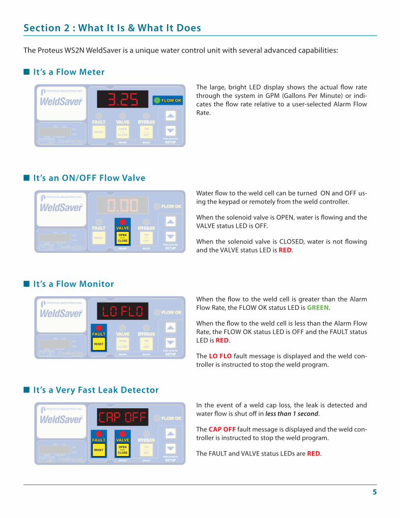
The Proteus WS2N WeldSaver is a unique water control unit with several advanced capabilities:
The large, bright LED display shows the actual flow rate through the system in GPM (Gallons Per Minute) or indi-cates the flow rate relative to a user-selected Alarm Flow Rate.
Water flow to the weld cell can be turned ON and OFF us-ing the keypad or remotely from the weld controller.
When the solenoid valve is OPEN, water is flowing and the VALVE status LED is OFF.
When the solenoid valve is CLOSED, water is not flowing and the VALVE status LED is rEd.
When the flow to the weld cell is greater than the Alarm Flow Rate, the FLOW OK status LED is grEEN.
When the flow to the weld cell is less than the Alarm Flow Rate, the FLOW OK status LED is OFF and the FAULT status LED is rEd.
The lO flO fault message is displayed and the weld con-troller is instructed to stop the weld program.
In the event of a weld cap loss, the leak is detected and water flow is shut off in less than 1 second.
The CAp Off fault message is displayed and the weld con-troller is instructed to stop the weld program.
The FAULT and VALVE status LEDs are rEd.
It’s a Flow Meter
It’s an ON/OFF Flow Valve
It’s a Flow Monitor
It’s a Very Fast Leak Detector
�
Section 3 : How It Works
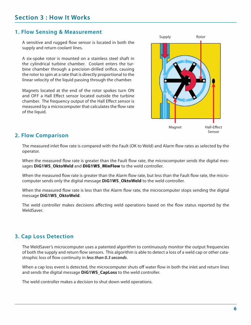
A sensitive and rugged flow sensor is located in both the supply and return coolant lines.
A six-spoke rotor is mounted on a stainless steel shaft in the cylindrical turbine chamber. Coolant enters the tur-bine chamber through a precision-drilled orifice, causing the rotor to spin at a rate that is directly proportional to the linear velocity of the liquid passing through the chamber.
Magnets located at the end of the rotor spokes turn ON and OFF a Hall Effect sensor located outside the turbine chamber. The frequency output of the Hall Effect sensor is measured by a microcomputer that calculates the flow rate of the liquid.
1. Flow Sensing & Measurement
The measured inlet flow rate is compared with the Fault (OK to Weld) and Alarm flow rates as selected by the operator.
When the measured flow rate is greater than the Fault flow rate, the microcomputer sends the digital mes-sages dig1wS_Oktoweld and DiG1WS_MinFlow to the weld controller.
When the measured flow rate is greater than the Alarm flow rate, but less than the Fault flow rate, the micro-computer sends only the digital message dig1wS_Oktoweld to the weld controller.
When the measured flow rate is less than the Alarm flow rate, the microcomputer stops sending the digital message dig1wS_Oktoweld.
The weld controller makes decisions affecting weld operations based on the flow status reported by the WeldSaver.
2. Flow Comparison
The WeldSaver’s microcomputer uses a patented algorithm to continuously monitor the output frequencies of both the supply and return flow sensors. This algorithm is able to detect a loss of a weld cap or other cata-strophic loss of flow continuity in less than 0.3 seconds.
When a cap loss event is detected, the microcomputer shuts off water flow in both the inlet and return lines and sends the digital message dig1wS_Caploss to the weld controller.
The weld controller makes a decision to shut down weld operations.
3. Cap Loss Detection
Supply
Hall-Effect Sensor
Rotor
Magnet
�
Section 4 : Installation & Testing
4.1 Mechanical Installation & Water Connections
Adjustable wrenchesPipe wrenchesTeflon-based pipe sealantMounting bolts x 4 to fit #8-32 mounting holesOr M5 x 12 mm screws for units fitted with a mounting bracket
••••
Tools required:
Refer to Figure 3 on Page 23 for dimensions and fastening locations.1.
Mechanical Installation
Flush the inlet piping.1.
Flushing, Making & Testing Water Connections
CAUTION!Flush contaminants and other accumulated construction debris from the up-stream water pipe beFOre connecting the WeldSaver.
Failure to flush coolant lines may result in the fouling of the WeldSaver’s supply flow sensor and clogging of smaller orifices in the robot supply lines, manifolds and the weld gun.
CAUTION!Flush contaminants and other debris from water lines connecting the robot, manifold, transformer, SCr and any other water-cooled components beFOre connecting them to the WeldSaver.
Failure to flush these lines may result in the fouling of the WeldSaver’s return flow sensor and clogging of smaller orifices in the robot supply lines, manifold, transformer, SCr, weld gun and any other water-cooled components.
Lubricate threads
Use a lubricating and non-hardening pipe sealant such as Teflon paste on all pipe threads. This material will lubricate and help seal NPT threaded pipe fittings.
2.
CAUTION!Do NOT allow excess pipe sealant to enter the flow sensors!
excess material may foul the sensors and cause clogging of smaller orifices in the robot’s supply lines, manifold, transformer, SCr, weld gun and any other water-cooled components.
�
Section 4 : Installation & Testing
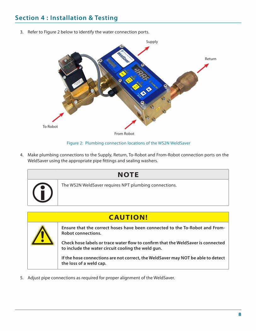
Refer to Figure 2 below to identify the water connection ports.3.
Make plumbing connections to the Supply, Return, To-Robot and From-Robot connection ports on the WeldSaver using the appropriate pipe fittings and sealing washers.
4.
NOTEThe WS2N WeldSaver requires NPT plumbing connections.
Figure 2: Plumbing connection locations of the WS2N WeldSaver
CAUTION!ensure that the correct hoses have been connected to the To-robot and From-robot connections.
Check hose labels or trace water flow to confirm that the WeldSaver is connected to include the water circuit cooling the weld gun.
If the hose connections are not correct, the WeldSaver may NOT be able to detect the loss of a weld cap.
Adjust pipe connections as required for proper alignment of the WeldSaver.5.
Supply
Return
To Robot
From Robot
�
Section 4 : Installation & Testing
Turn water ON slowly.7.
wArNINg!The WeldSaver body is NOT insulated!
When using the WeldSaver with hot liquids, use proper personal protective equipment.
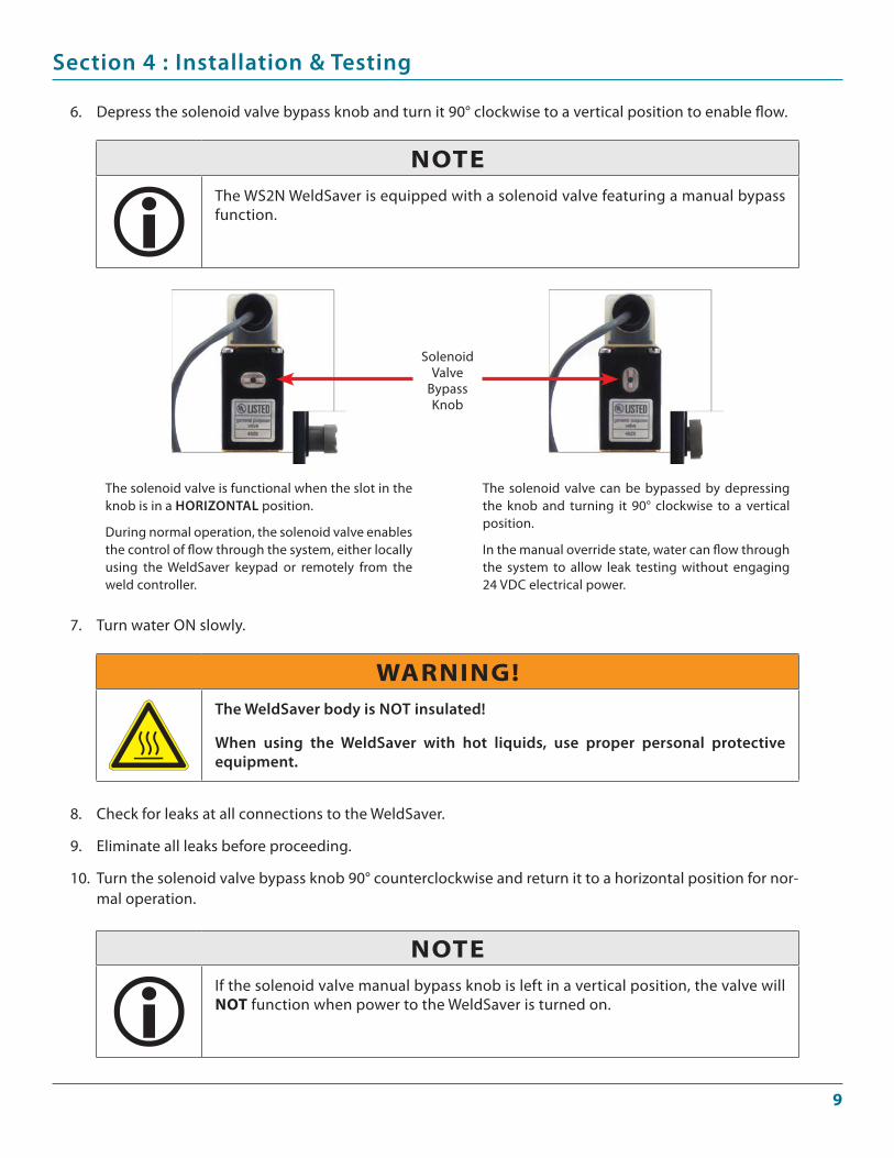
Depress the solenoid valve bypass knob and turn it 90° clockwise to a vertical position to enable flow.6.
NOTEThe WS2N WeldSaver is equipped with a solenoid valve featuring a manual bypass function.
The solenoid valve is functional when the slot in the knob is in a HOrIzONTaL position.
During normal operation, the solenoid valve enables the control of flow through the system, either locally using the WeldSaver keypad or remotely from the weld controller.
The solenoid valve can be bypassed by depressing the knob and turning it 90° clockwise to a vertical position.
In the manual override state, water can flow through the system to allow leak testing without engaging 24 VDC electrical power.
Solenoid Valve
Bypass Knob
Check for leaks at all connections to the WeldSaver.
Eliminate all leaks before proceeding.
Turn the solenoid valve bypass knob 90° counterclockwise and return it to a horizontal position for nor-mal operation.
8.
9.
10.
NOTEIf the solenoid valve manual bypass knob is left in a vertical position, the valve will NOT function when power to the WeldSaver is turned on.
10
Section 4 : Installation & Testing
Refer to Figure 3 above to identify the 24 VDC power interface connections.
Confirm that the auxiliary power cable has 24 VDC present between pins 2 and 3.
1.
2.
4.2 electrical & DeviceNet® Connections
Connecting 24 VDC auxiliary Power
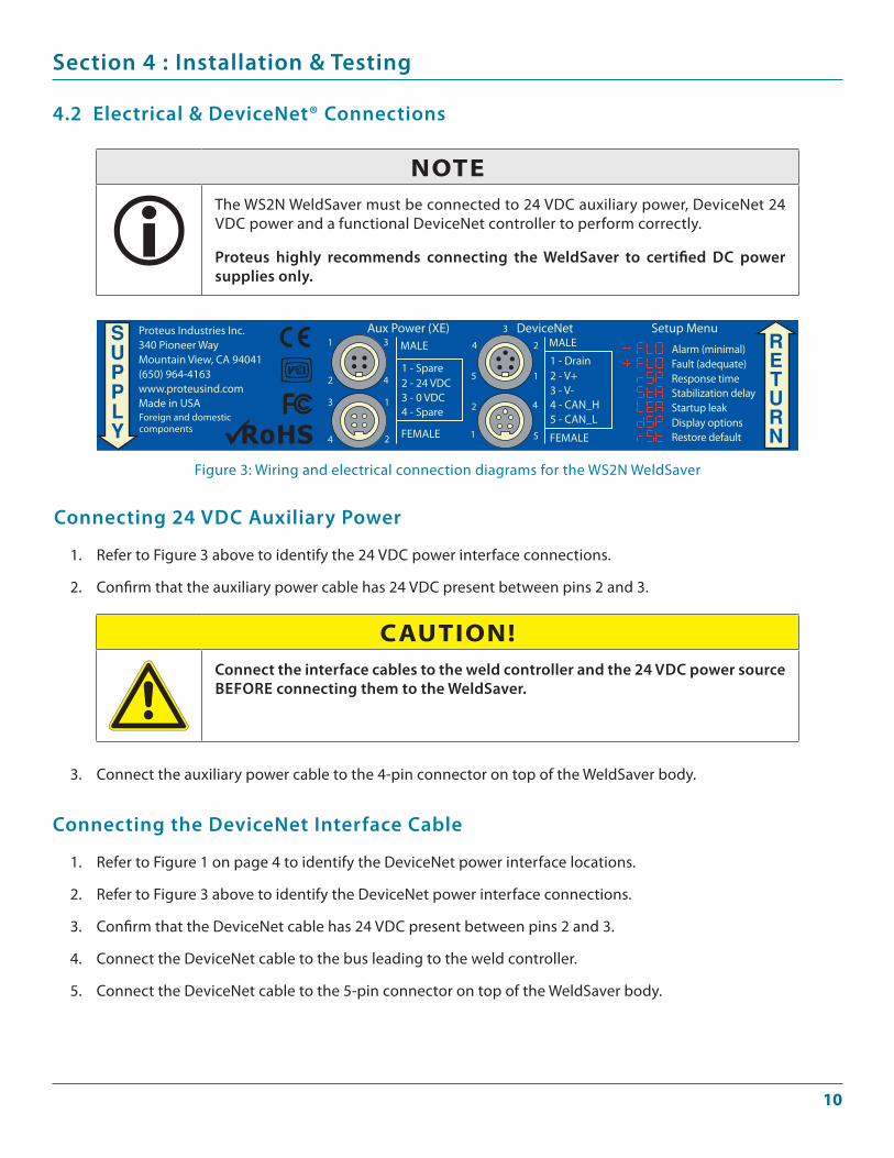
Proteus Industries Inc.340 Pioneer WayMountain View, CA 94041(650) 964-4163www.proteusind.comMade in USAForeign and domesticcomponents
1 3
2 4
3 1
4 2
4
3
2
5 1
2 4
1 5
Aux Power (XE) DeviceNet Setup MenuMALE
FEMALE
1 - Spare2 - 24 VDC3 - 0 VDC4 - Spare
MALE
FEMALE
1 - Drain2 - V+3 - V-4 - CAN_H5 - CAN_L
Alarm (minimal)Fault (adequate)Response timeStabilization delayStartup leakDisplay optionsRestore default
CAUTION!Connect the interface cables to the weld controller and the 24 VDC power source beFOre connecting them to the WeldSaver.
Connect the auxiliary power cable to the 4-pin connector on top of the WeldSaver body.3.
NOTEThe WS2N WeldSaver must be connected to 24 VDC auxiliary power, DeviceNet 24 VDC power and a functional DeviceNet controller to perform correctly.
Proteus highly recommends connecting the WeldSaver to certified DC power supplies only.
Figure 3: Wiring and electrical connection diagrams for the WS2N WeldSaver
Refer to Figure 1 on page 4 to identify the DeviceNet power interface locations.
Refer to Figure 3 above to identify the DeviceNet power interface connections.
Confirm that the DeviceNet cable has 24 VDC present between pins 2 and 3.
Connect the DeviceNet cable to the bus leading to the weld controller.
Connect the DeviceNet cable to the 5-pin connector on top of the WeldSaver body.
1.
2.
3.
4.
5.
Connecting the DeviceNet Interface Cable
11
Section 4 : Installation & Testing
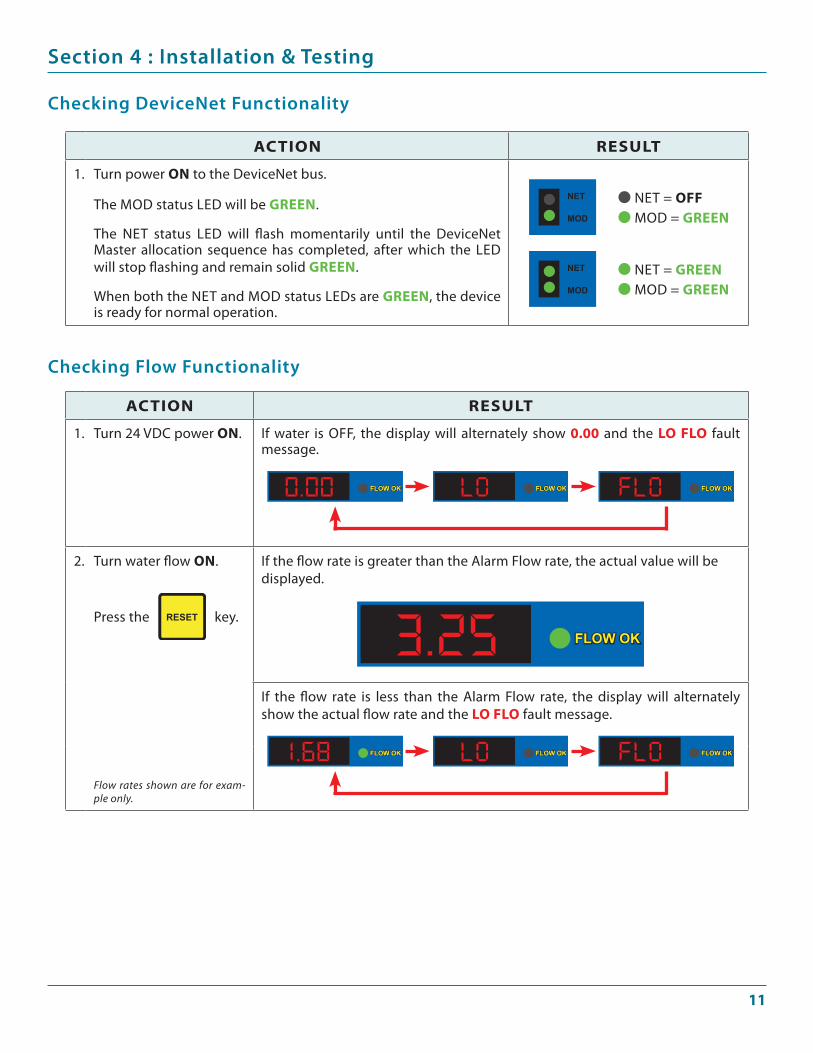
Checking DeviceNet Functionality
ACTION rESUlT
1. Turn power ON to the DeviceNet bus.
The MOD status LED will be grEEN.
The NET status LED will flash momentarily until the DeviceNet Master allocation sequence has completed, after which the LED will stop flashing and remain solid grEEN.
When both the NET and MOD status LEDs are grEEN, the device is ready for normal operation.
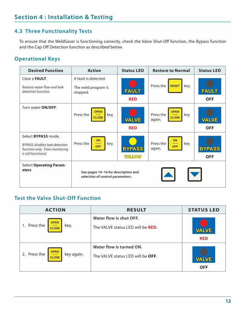
Checking Flow Functionality
NET = OffMOD = grEEN
NET = grEENMOD = grEEN
ACTION rESUlT
1. Turn 24 VDC power ON. If water is OFF, the display will alternately show 0.00 and the lO flO fault message.
2. Turn water flow ON.
Press the key.
If the flow rate is greater than the Alarm Flow rate, the actual value will be displayed.
If the flow rate is less than the Alarm Flow rate, the display will alternately show the actual flow rate and the lO flO fault message.
Flow rates shown are for exam-ple only.
1�
Section 4 : Installation & Testing
To ensure that the WeldSaver is functioning correctly, check the Valve Shut-Off function, the Bypass function and the Cap Off Detection function as described below.
4.3 Three Functionality Tests
Operational Keys
desired function Action Status lEd restore to Normal Status lEd
Clear a fAUlT.
Restarts water flow and leak detection function.
A fault is detected.
The weld program is stopped.
rEd
Press the key.
Off
Turn water ON/Off.
Press the key.
rEd
Press the key again.
Off
Select bypASS mode.
bypass disables leak detection function only. Flow monitoring is still functional.
Press the key.
yEllOw
Press the key again.
Off
Select Operating param-eters See pages 14–16 for description and
selection of control parameters.
Test the Valve Shut-Off Function
ACTION rESUlT STATUS lEd
1. Press the key.
Water flow is shut OFF.
The VALVE status LED will be rEd.
rEd
2. Press the key again.
Water flow is turned ON.
The VALVE status LED will be Off.
Off
1�
Section 4 : Installation & Testing
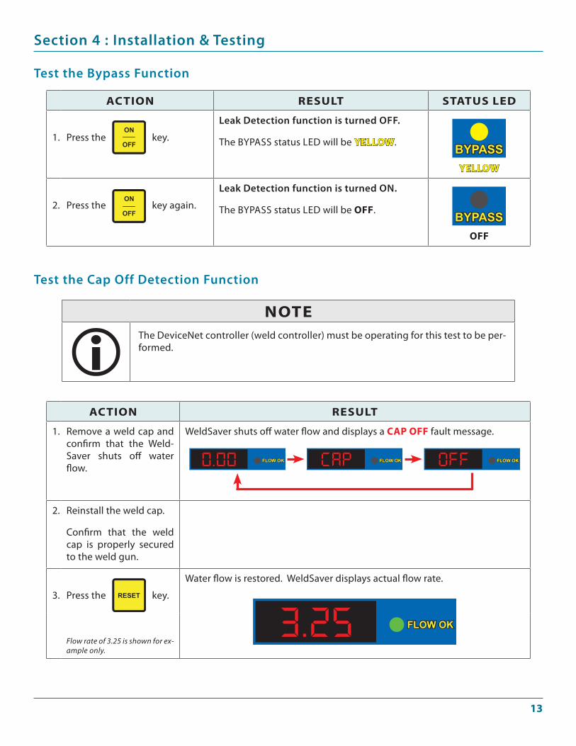
Test the Cap Off Detection Function
ACTION rESUlT
1. Remove a weld cap and confirm that the Weld-Saver shuts off water flow.
WeldSaver shuts off water flow and displays a CAp Off fault message.
2. Reinstall the weld cap.
Confirm that the weld cap is properly secured to the weld gun.
3. Press the key.
Water flow is restored. WeldSaver displays actual flow rate.
Flow rate of 3.25 is shown for ex-ample only.
Test the bypass Function
ACTION rESUlT STATUS lEd
1. Press the key.
Leak Detection function is turned OFF.
The ByPASS status LED will be yEllOw.
yEllOw
2. Press the key again.
Leak Detection function is turned ON.
The ByPASS status LED will be Off.
Off
NOTEThe DeviceNet controller (weld controller) must be operating for this test to be per-formed.
1�
Section 5 : Selecting Control Parameter Values
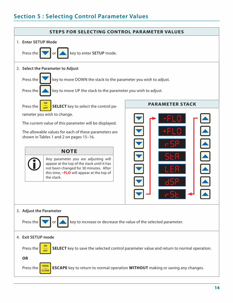
STEpS fOr SElECTINg CONTrOl pArAmETEr vAlUES
1. enter SeTuP Mode
Press the or key to enter SeTuP mode.
2. Select the Parameter to adjust
Press the key to move DOWN the stack to the parameter you wish to adjust.
Press the key to move UP the stack to the parameter you wish to adjust.
Press the SElECT key to select the control pa-
rameter you wish to change.
The current value of this parameter will be displayed.
The allowable values for each of these parameters are shown in Tables 1 and 2 on pages 15–16.
pArAmETEr STACk
3. adjust the Parameter
Press the or key to increase or decrease the value of the selected parameter.
4. exit SeTuP mode
Press the SElECT key to save the selected control parameter value and return to normal operation.
Or
Press the ESCApE key to return to normal operation wIThOUT making or saving any changes.
NOTEAny parameter you are adjusting will appear at the top of the stack until it has not been changed for 30 minutes. After this time, –flO will appear at the top of the stack.

1�
Section 5 : Selecting Control Parameter Values
Parameter Values for the WS2N3 WeldSaver
STaCKSyMbOL CONTrOL ParaMeTer PreSeT
VaLue DeSCrIPTION & NOTeS
alarm Flow Trip Point
GPM
0.4 GPM
This is the lowest flow rate at which the welding system should be operated. Coolant flow lower than this rate does not provide sufficient cooling capacity to allow satisfactory welds to be pro-duced.
Range 0–3
Increments 0.2
Fault Flow Trip Point
GPM
0.8 GPM
This is the flow rate at which the weld system should be operated. This flow rate provides suf-ficient cooling capacity to allow welds at the de-sired rate under all ambient temperature condi-tions.
Range 0–3
Increments 0.2
Leak response
-SLO SLO nOr FAS +FAS nOr
This setting determines how quickly a leak will be detected. Slowing the response reduces sensitiv-ity to false cap-loss events; speeding the response increases sensitivity.
Startup Stabilization Delay Time
1 S 2 S 4 S 8 S 16 S 2 Seconds
This setting selects the amount of time required to purge air from the cooling system at startup that could otherwise cause false cap-loss events.
Startup Leak Detection Threshold
GPM
0.5 GPM
This setting checks whether the weld cap is prop-erly in place and is not ejected from the weld shank when water pressure is applied. A low set-ting gives the most sensitive response to the loss of a weld cap at startup; a high setting gives the least sensitive response.
0.5 1.0 1.5 2.0 2.5
absolute or relative Flow Display
AbS Displays actual flow rate
-rEL Relative to Alarm flow rate
+rEL Relative to Fault flow rate
AbS
The Absolute flow rate is normally used. The Rela-tive displays can be used to check the actual flow against the Alarm or Fault flow rates.
restore Parameter to Factory Setup Values
nO yES N/A
This key allows all parameters to be restored to their specified default values.
Table 1: Parameter descriptions, ranges and factory setup values for the WS2N3 WeldSaver
1�
Section 5 : Selecting Control Parameter Values
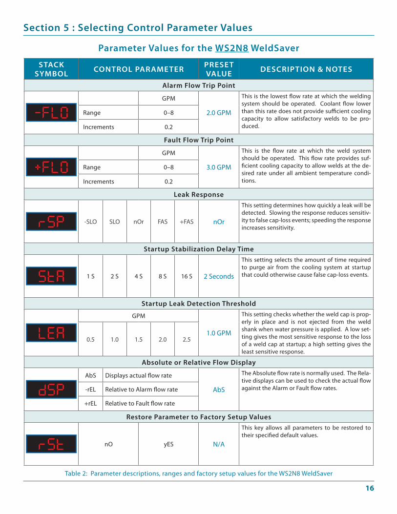
Parameter Values for the WS2N8 WeldSaver
STaCKSyMbOL CONTrOL ParaMeTer PreSeT
VaLue DeSCrIPTION & NOTeS
alarm Flow Trip Point
GPM
2.0 GPM
This is the lowest flow rate at which the welding system should be operated. Coolant flow lower than this rate does not provide sufficient cooling capacity to allow satisfactory welds to be pro-duced.
Range 0–8
Increments 0.2
Fault Flow Trip Point
GPM
3.0 GPM
This is the flow rate at which the weld system should be operated. This flow rate provides suf-ficient cooling capacity to allow welds at the de-sired rate under all ambient temperature condi-tions.
Range 0–8
Increments 0.2
Leak response
-SLO SLO nOr FAS +FAS nOr
This setting determines how quickly a leak will be detected. Slowing the response reduces sensitiv-ity to false cap-loss events; speeding the response increases sensitivity.
Startup Stabilization Delay Time
1 S 2 S 4 S 8 S 16 S 2 Seconds
This setting selects the amount of time required to purge air from the cooling system at startup that could otherwise cause false cap-loss events.
Startup Leak Detection Threshold
GPM
1.0 GPM
This setting checks whether the weld cap is prop-erly in place and is not ejected from the weld shank when water pressure is applied. A low set-ting gives the most sensitive response to the loss of a weld cap at startup; a high setting gives the least sensitive response.
0.5 1.0 1.5 2.0 2.5
absolute or relative Flow Display
AbS Displays actual flow rate
-rEL Relative to Alarm flow rate
+rEL Relative to Fault flow rate
AbS
The Absolute flow rate is normally used. The Rela-tive displays can be used to check the actual flow against the Alarm or Fault flow rates.
restore Parameter to Factory Setup Values
nO yES N/A
This key allows all parameters to be restored to their specified default values.
Table 2: Parameter descriptions, ranges and factory setup values for the WS2N8 WeldSaver
1�
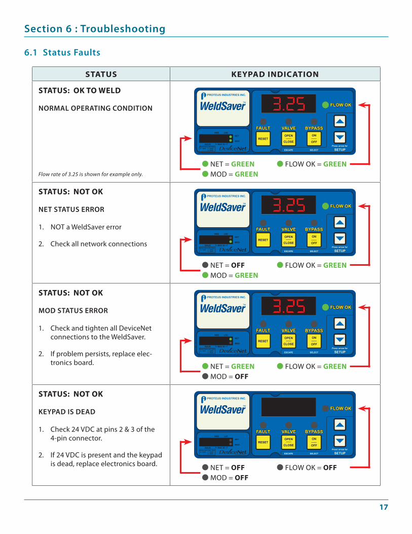
Section 6 : Troubleshooting
6.1 Status Faults
STATUS kEypAd INdICATION
STATUS: Ok TO wEld
NOrMaL OPeraTINg CONDITION
Flow rate of 3.25 is shown for example only.
STATUS: NOT Ok
NeT STaTuS errOr
NOT a WeldSaver error
Check all network connections
1.
2.
STATUS: NOT Ok
MOD STaTuS errOr
Check and tighten all DeviceNet connections to the WeldSaver.
If problem persists, replace elec-tronics board.
1.
2.
STATUS: NOT Ok
KeyPaD IS DeaD
Check 24 VDC at pins 2 & 3 of the 4-pin connector.
If 24 VDC is present and the keypad is dead, replace electronics board.
1.
2.
NET = grEENMOD = grEEN
FLOW OK = grEEN
NET = OffMOD = grEEN
FLOW OK = grEEN
NET = grEENMOD = Off
FLOW OK = grEEN
NET = OffMOD = Off
FLOW OK = Off
1�
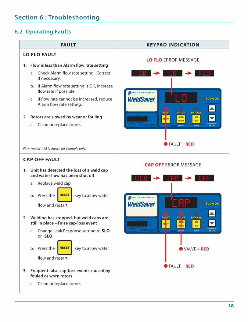
Section 6 : Troubleshooting
6.2 Operating Faults
fAUlT kEypAd INdICATION
lO flO fAUlT
Flow is less than alarm flow rate setting
Check Alarm flow rate setting. Correct If necessary.
If Alarm flow rate setting is OK, increase flow rate if possible.
If flow rate cannot be increased, reduce Alarm flow rate setting.
rotors are slowed by wear or fouling
Clean or replace rotors.
Flow rate of 1.68 is shown for example only.
1.
a.
b.
c.
2.
a.
CAp Off fAUlT
unit has detected the loss of a weld cap and water flow has been shut off
Replace weld cap.
Press the key to allow water
flow and restart.
Welding has stopped, but weld caps are still in place – False cap-loss event
Change Leak Response setting to SlO or -SlO.
Press the key to allow water
flow and restart.
Frequent false cap-loss events caused by fouled or worn rotors
Clean or replace rotors.
1.
a.
b.
2.
a.
b.
3.
a.
FAULT = rEd
lO flO ERROR MESSAGE
FAULT = rEd
CAp Off ERROR MESSAGE
VALVE = rEd
1�
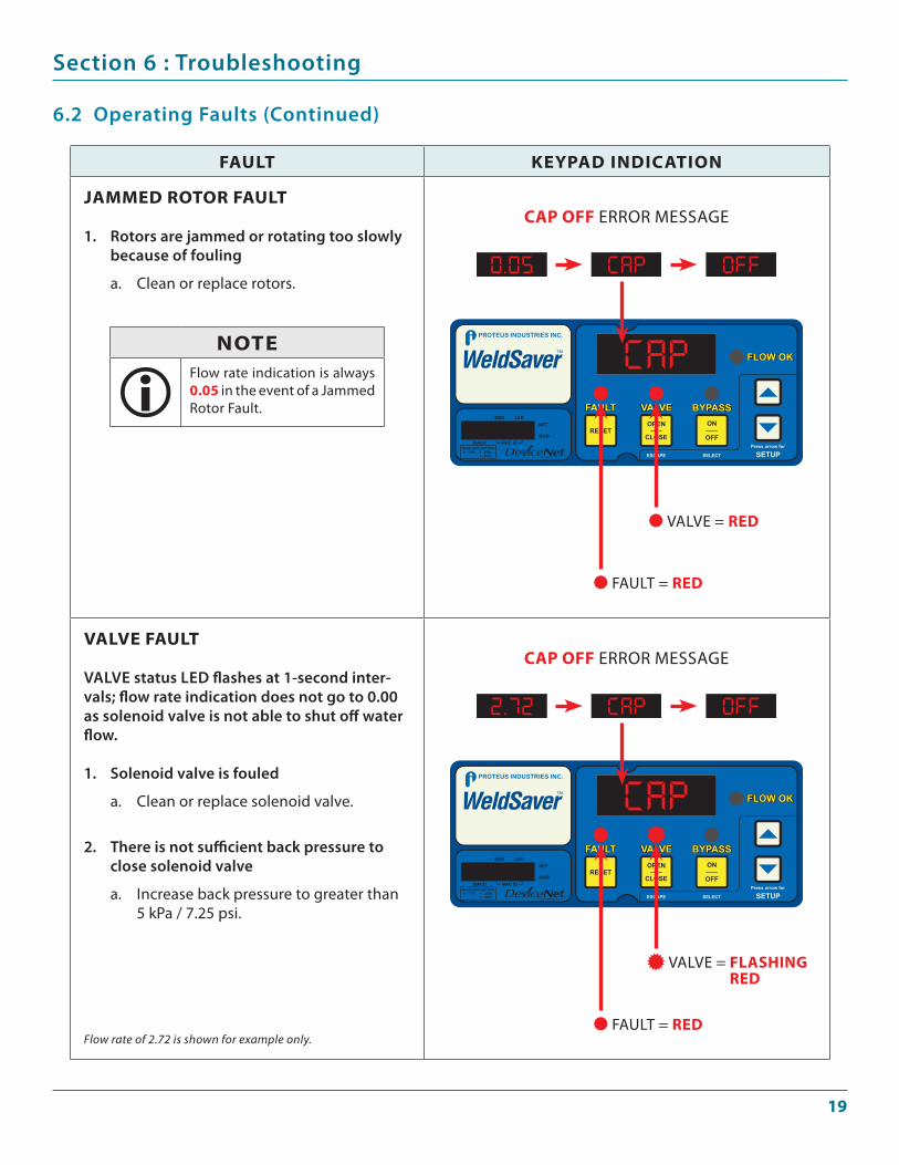
Section 6 : Troubleshooting
6.2 Operating Faults (Continued)
fAUlT kEypAd INdICATION
JAmmEd rOTOr fAUlT
rotors are jammed or rotating too slowly because of fouling
Clean or replace rotors.
1.
a.
vAlvE fAUlT
VaLVe status LeD flashes at 1-second inter-vals; flow rate indication does not go to 0.00 as solenoid valve is not able to shut off water flow.
Solenoid valve is fouled
Clean or replace solenoid valve.
There is not sufficient back pressure to close solenoid valve
Increase back pressure to greater than 5 kPa / 7.25 psi.
Flow rate of 2.72 is shown for example only.
1.
a.
2.
a.
NOTEFlow rate indication is always 0.0� in the event of a Jammed Rotor Fault.
FAULT = rEd
CAp Off ERROR MESSAGE
VALVE = rEd
FAULT = rEd
CAp Off ERROR MESSAGE
VALVE = flAShINg rEd
�0
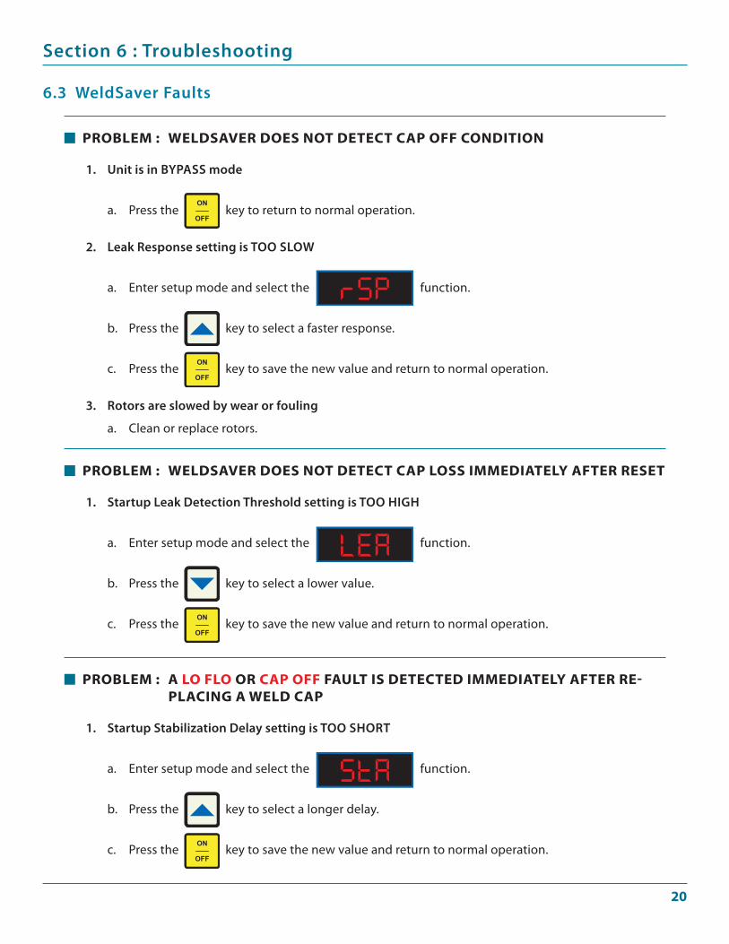
prOblEm : A lO flO Or CAp Off fAUlT IS dETECTEd ImmEdIATEly AfTEr rE-plACINg A wEld CAp
Startup Stabilization Delay setting is TOO SHOrT
Enter setup mode and select the function.
Press the key to select a longer delay.
Press the key to save the new value and return to normal operation.
1.
a.
b.
c.
prOblEm : wEldSAvEr dOES NOT dETECT CAp lOSS ImmEdIATEly AfTEr rESET
Startup Leak Detection Threshold setting is TOO HIgH
Enter setup mode and select the function.
Press the key to select a lower value.
Press the key to save the new value and return to normal operation.
1.
a.
b.
c.
Section 6 : Troubleshooting
6.3 WeldSaver Faults
prOblEm : wEldSAvEr dOES NOT dETECT CAp Off CONdITION
unit is in byPaSS mode
Press the key to return to normal operation.
Leak response setting is TOO SLOW
Enter setup mode and select the function.
Press the key to select a faster response.
Press the key to save the new value and return to normal operation.
rotors are slowed by wear or fouling
Clean or replace rotors.
1.
a.
2.
a.
b.
c.
3.
a.
�1
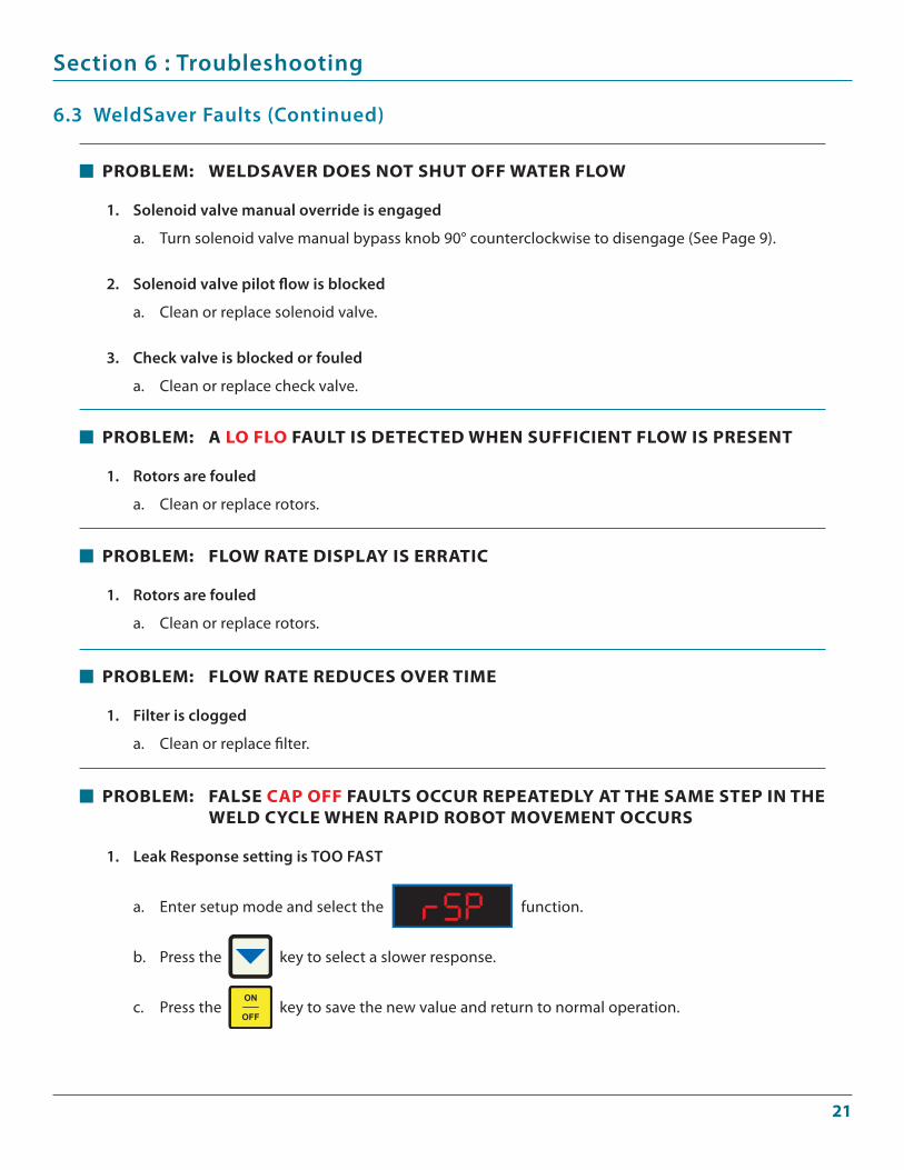
prOblEm: fAlSE CAp Off fAUlTS OCCUr rEpEATEdly AT ThE SAmE STEp IN ThE wEld CyClE whEN rApId rObOT mOvEmENT OCCUrS
Leak response setting is TOO FaST
Enter setup mode and select the function.
Press the key to select a slower response.
Press the key to save the new value and return to normal operation.
1.
a.
b.
c.
prOblEm: flOw rATE rEdUCES OvEr TImE
Filter is clogged
Clean or replace filter.
1.
a.
prOblEm: flOw rATE dISplAy IS ErrATIC
rotors are fouled
Clean or replace rotors.
1.
a.
prOblEm: A lO flO fAUlT IS dETECTEd whEN SUffICIENT flOw IS prESENT
rotors are fouled
Clean or replace rotors.
1.
a.
Section 6 : Troubleshooting
6.3 WeldSaver Faults (Continued)
prOblEm: wEldSAvEr dOES NOT ShUT Off wATEr flOw
Solenoid valve manual override is engaged
Turn solenoid valve manual bypass knob 90° counterclockwise to disengage (See Page 9).
Solenoid valve pilot flow is blocked
Clean or replace solenoid valve.
Check valve is blocked or fouled
Clean or replace check valve.
1.
a.
2.
a.
3.
a.
��
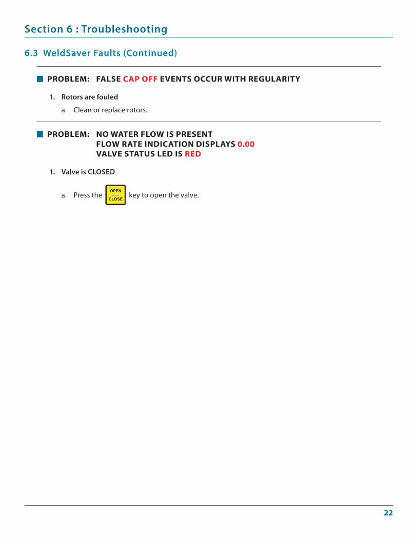
prOblEm: NO wATEr flOw IS prESENT flOw rATE INdICATION dISplAyS 0.00 vAlvE STATUS lEd IS rEd
Valve is CLOSeD
Press the key to open the valve.
1.
a.
Section 6 : Troubleshooting
6.3 WeldSaver Faults (Continued)
prOblEm: fAlSE CAp Off EvENTS OCCUr wITh rEgUlArITy
rotors are fouled
Clean or replace rotors.
1.
a.
��
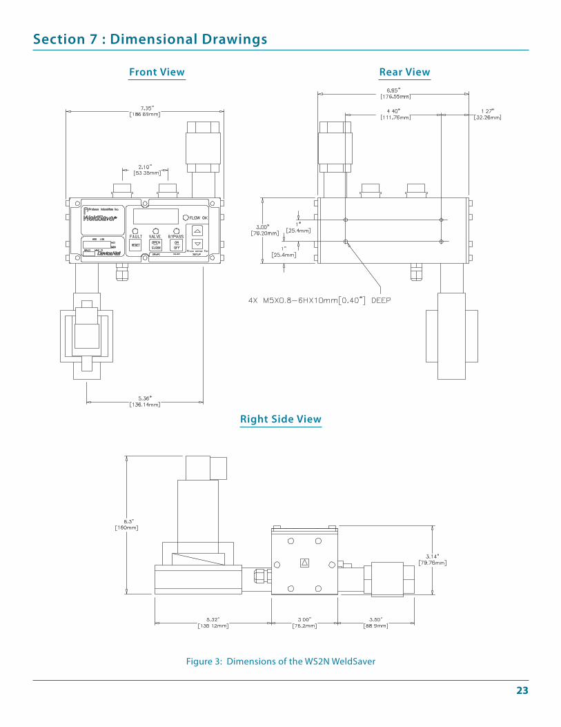
Section 7 : Dimensional Drawings
Front View rear View
right Side View
Figure 3: Dimensions of the WS2N WeldSaver