Embed Size (px)
Citation preview
Protectionand control
Sepam rangeSepam 2000Transformer
2 Transformer
page
presentation 2
selection table 3
metering 5
protection 7
control and monitoring 10
functional and connection schemes 13
other connection schemes 21
communication 26
characteristics 27
installation 28
ordering information 32
Presentation
Contents
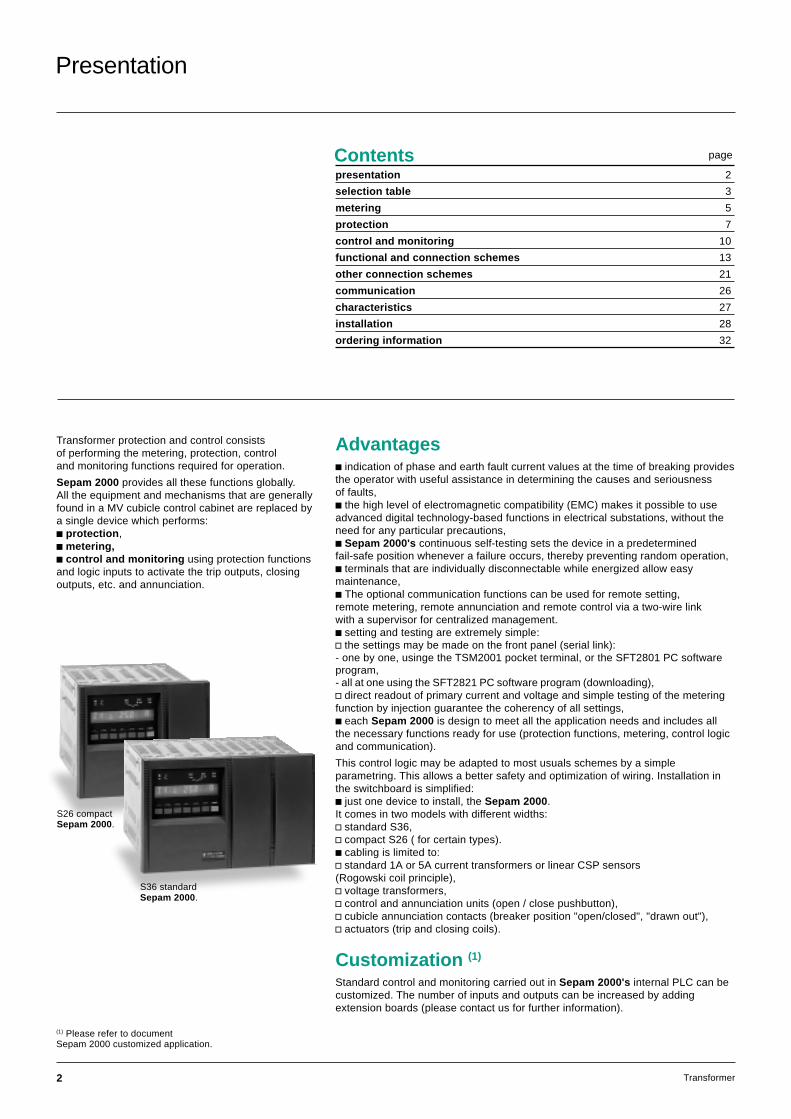
Transformer protection and control consistsof performing the metering, protection, controland monitoring functions required for operation.
Sepam 2000 provides all these functions globally.All the equipment and mechanisms that are generallyfound in a MV cubicle control cabinet are replaced bya single device which performs:c protection,c metering,c control and monitoring using protection functionsand logic inputs to activate the trip outputs, closingoutputs, etc. and annunciation.
Advantagesc indication of phase and earth fault current values at the time of breaking providesthe operator with useful assistance in determining the causes and seriousnessof faults,c the high level of electromagnetic compatibility (EMC) makes it possible to useadvanced digital technology-based functions in electrical substations, without theneed for any particular precautions,c Sepam 2000's continuous self-testing sets the device in a predeterminedfail-safe position whenever a failure occurs, thereby preventing random operation,c terminals that are individually disconnectable while energized allow easymaintenance,c The optional communication functions can be used for remote setting,remote metering, remote annunciation and remote control via a two-wire linkwith a supervisor for centralized management.c setting and testing are extremely simple:v the settings may be made on the front panel (serial link):- one by one, usinge the TSM2001 pocket terminal, or the SFT2801 PC softwareprogram,- all at one using the SFT2821 PC software program (downloading),v direct readout of primary current and voltage and simple testing of the meteringfunction by injection guarantee the coherency of all settings,c each Sepam 2000 is design to meet all the application needs and includes allthe necessary functions ready for use (protection functions, metering, control logicand communication).
This control logic may be adapted to most usuals schemes by a simpleparametring. This allows a better safety and optimization of wiring. Installation inthe switchboard is simplified:c just one device to install, the Sepam 2000.It comes in two models with different widths:v standard S36,v compact S26 ( for certain types).c cabling is limited to:v standard 1A or 5A current transformers or linear CSP sensors(Rogowski coil principle),v voltage transformers,v control and annunciation units (open / close pushbutton),v cubicle annunciation contacts (breaker position "open/closed", "drawn out"),v actuators (trip and closing coils).
Customization (1)
Standard control and monitoring carried out in Sepam 2000's internal PLC can becustomized. The number of inputs and outputs can be increased by addingextension boards (please contact us for further information).
S26 compactSepam 2000.
S36 standardSepam 2000.
(1) Please refer to documentSepam 2000 customized application.

3Transformer
Selection table
functions ANSI Sepam types (2)
code T01 T02 T03 T04 T05 T06 T07 T09 T10 T11 T12 T13 T14 T15 T16 T17 T18 T19protectionthermal overload 49 1 1 1 1 1 1 1 1 1 1 1 1 1 1 1 1 1 1phase overcurrent 50/51 4 4 4 4 4 4 4 4 4 4 4 4 4 4 4 4 4 4earth fault (sensitive E/F) 50N/ 4 4 4 4 4 4 4 4 4 4 4 4 4 4 4 4 4 4
51N(G)neutral voltage displacement 59N 1 1 1 1 1 1 1 1 1 1 1directional overcurrent 67 1 1 1 1 1directional earth fault 67N 1 1 1 1 1 1 1 1tank earth leakage (3)(4) 50/51 1 1 1 1 1 1 1neutral (3) 50N/ 2 2 2 2 2 2 2
51Nundervoltage 27 1 1 1 1undervoltage remanent 27R 1 1 1 1overvoltage 59 2 2 2 2restricted earth fault (4) 64REF 1 1 1 1 1 1 1meteringphase currents (I1, I2, I3) c c c/c* c c c/c* c/c* c c c c/c* c/c* c c/c* c c c/c* cpeak demand phase currents (I1, I2, I3) c c c c c c c c c c c c c c c c c cvoltage (U21, U32, U13, V1, V2, V3) c c c c c c c c c c c c c c creal/ reactive power (P, Q) c c c c c c c c c c c c c c cpeak demand real/ reactive power c c c c c c c c c c c c c c cpower factor c c c c c c c c c c c c c c cfrequency c c c c c c c c c c c c c c cthermal capacity used c c c c c c c c c c c c c c c c c caccumulated real/ reactive energy c c c c c c c c c c c c c c c(±Wh, ±VArh)tripping currents c c c c c c c c c c c c c c c c c c(I1, I2, I3, Io)true rms current c c c c c c c c c c c c c c c c c cdisturbance recording c c c c c c c c c c c c c c c c c cresidual current c c c/c* c c c/c* c/c* c c c c/c* c/c* c c/c* c c c/c* cresidual voltage c c c c c c c c c c c c c c ccumulative breaking current c c c c c c c c c c c c c c c c c cand number of breakscontrol and monitoringopen / close c c c c c c c c c c c c c c c c c clockout relay 86 c c c c c c c c c c c c c c c c c cinhibit closing 69 c c c c c c c c c c c c c c c c c cannunciation 30 c c c c c c c c c c c c c c c c c cBuchholz thermal relay c c c c c c c c c c cdetection of gas, pressureand temperature level (DGPT/ PTC)inter-tripping (1) c c c c c c c c c c clogic discriminition 68 c c c c c c c c c c c c c c c c c ctrip circuit supervision 74 c c c c c c c c c c c c c c c c c cdetection of plugged 74 c c c c c c c c c c c c c c c c c cconnectors (DPC)operation counter c c c c c c c c c c c c c c c c c cphase fault trip counter c c c c c c c c c c c c c c c c c cdisturbance recording triggering c c c c c c c c c c c c c c c c c cSepam modelsstandard S36 YR XR KR YR XR LR LR XR XR XR LR LR XR LR XR XR LR XRcompact S26 LX LT LX LT LT LT LT LT LT LT LTnumber of standard ESTOR boards 2 2 2 1 1 2 1 2 2 1 1 1 2 2 1 2 2 2
Sepam 2000 transformer without RTDs
The figures in the columns represent the number of similar protection devices.Example: for phase overcurrent protection, “4” means 4 separate phase overcurrent protection devices.(1) inter-tripping: this is related to neutral voltage displacement, tank earth leakage, neutral protection functions and Buchholz tripping, gas detector tripping,pressure detector functions.(2) for transformers which require RTDs, see the chart on the next page. For differential protection, see Sepam 2000 D22 and Sepam 100LD.(3) types of Sepam 2000 with tank earth leakage and neutral can’t be connected to CSP sensors.(4) the tank earth leakage and restricted earth fault protections are exclusive. The choice is made by parameter setting. See other connection schemesfor restricted earth fault.* available function on 2 sets of sensors.
4 Transformer
Selection table (cont'd)
functions ANSI Sepam types (2)
code T21 T22 T23 T24 T25 T26 T27 T29 T30 T31 T32 T33 T34 T35 T36 T37 T38 T39protectionthermal overload 49 1 1 1 1 1 1 1 1 1 1 1 1 1 1 1 1 1 1phase overcurrent 50/51 4 4 4 4 4 4 4 4 4 4 4 4 4 4 4 4 4 4earth fault (sensitive E/F) 50N/ 4 4 4 4 4 4 4 4 4 4 4 4 4 4 4 4 4 4
51N(G)neutral voltage displacement 59N 1 1 1 1 1 1 1 1 1 1 1directional overcurrent 67 1 1 1 1 1directional earth fault 67N 1 1 1 1 1 1 1 1tank earth leakage (3)(4) 50/51 1 1 1 1 1 1 1neutral (3) 50N/ 2 2 2 2 2 2 2
51Nundervoltage 27 1 1 1 1undervoltage remanent 27R 1 1 1 1overvoltage 59 2 2 2 2temperature set point (6 RTDs) 38/49T 6 6 6 6 6 6 6 6 6 6 6 6 6 6 6 6 6 6restricted earth fault (4) 64REF 1 1 1 1 1 1 1meteringphase currents (I1, I2, I3) c c c/c* c c c/c* c/c* c c c c/c* c/c* c c/c* c c c/c* cpeak demand phase currents (I1, I2, I3) c c c c c c c c c c c c c c c c c cvoltage (U21, U32, U13, V1, V2, V3) c c c c c c c c c c c c c c creal/ reactive power (P, Q) c c c c c c c c c c c c c c cpeak demand real/ reactive power c c c c c c c c c c c c c c cpower factor c c c c c c c c c c c c c c cfrequency c c c c c c c c c c c c c c cthermal capacity used c c c c c c c c c c c c c c c c c caccumulated real/ reactive energy c c c c c c c c c c c c c c c(±Wh, ±VArh)tripping currents c c c c c c c c c c c c c c c c c c(I1, I2, I3, Io)true rms current c c c c c c c c c c c c c c c c c cdisturbance recording c c c c c c c c c c c c c c c c c ctemperature (6 RTDs) c c c c c c c c c c c c c c c c c cresidual current c c c/c* c c c/c* c/c* c c c c/c* c/c* c c/c* c c c/c* cresidual voltage c c c c c c c c c c c c c c ccumulative breaking current c c c c c c c c c c c c c c c c c cand number of breakscontrol and monitoringopen / close c c c c c c c c c c c c c c c c c clockout relay 86 c c c c c c c c c c c c c c c c c cinhibit closing 69 c c c c c c c c c c c c c c c c c cannunciation 30 c c c c c c c c c c c c c c c c c cBuchholz thermal relay c c c c c c c c c c cdetection of gas, pressureand temperature level (DGPT/ PTC)inter-tripping (1) c c c c c c c c c c clogic discriminition 68 c c c c c c c c c c c c c c c c c ctrip circuit supervision 74 c c c c c c c c c c c c c c c c c cdetection of plugged 74 c c c c c c c c c c c c c c c c c cconnectors (DPC)operation counter c c c c c c c c c c c c c c c c c cphase fault trip counter c c c c c c c c c c c c c c c c c cdisturbance recording triggering c c c c c c c c c c c c c c c c c cSepam modelsstandard S36 ZR SR KZ ZR SR LS LS SR SR SR LS LS SR LS SR SR LS SRcompact S26 LS LSnumber of standard ESTOR boards 2 2 2 1 1 2 1 2 2 1 1 1 2 2 1 2 2 2
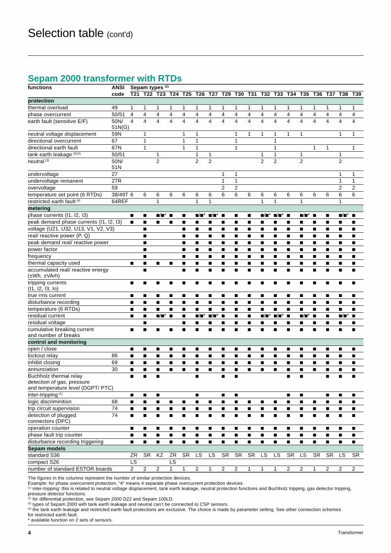
Sepam 2000 transformer with RTDs
The figures in the columns represent the number of similar protection devices.Example: for phase overcurrent protection, “4” means 4 separate phase overcurrent protection devices.(1) inter-tripping: this is related to neutral voltage displacement, tank earth leakage, neutral protection functions and Buchholz tripping, gas detector tripping,pressure detector functions.(2) for differential protection, see Sepam 2000 D22 and Sepam 100LD.(3) types of Sepam 2000 with tank earth leakage and neutral can’t be connected to CSP sensors.(4) the tank earth leakage and restricted earth fault protections are exclusive. The choice is made by parameter setting. See other connection schemesfor restricted earth fault.* available function on 2 sets of sensors.
5Transformer
Metering
Sepam 2000 is an accurate metering device.It gives a direct readout of values,together with the related units, A, V, W...All the values needed for operation and usedfor commissioning are available locallyand in the control room.
Measurements needed for operation
CurrentsMeasurement of the current for each of the 3 phases of the circuit.
Peak demand currentsMeasurement of the greatest average current value on the 3 phases.The average current measurement is computed periodically (adjustable period: 5,10, 15, 30 or 60 minutes).
The “clear” button is pressed for zero reset.
VoltagesMeasurement of the circuit phase-to-phase and phase-to-neutral voltages.
Real / reactive powerMeasurement of the real and reactive power, with the sign, in balancedand unbalanced 3-phase networks.
Peak demand real / reactive powerMeasurement of the greatest average real power (and reactive power) value, used to find the power absorbed during peak load periods. The average valueis computed periodically (adjustable period: 5, 10, 15, 30 or 60 minutes).The “clear” button is pressed for zero reset.
Power factor (p.f.)Measurement of the power factor, with the sign and type (capacitive or inductive),of the power absorbed.
FrequencyMeasurement of frequency (based on positive sequence voltage or the U21 voltageinput).
Thermal capacity usedMeasurement of the relative thermal capacity used (with respect to the nominalthermal capacity) on account of the load.
Real and reactive energyThe alphanumerical display unit shows the 4 accumulated real / reactive energyvalues:c real energy consumed,c reverse real energy,c reactive energy consumed,c reverse reactive energy.
The accumulated values are saved in the event of a power failure.
Tripping currentsMeasurements of the 3 phase currents and the residual current that were storedat the time that Sepam 2000 gave the tripping order. Used to find the fault current(fault analysis) and assess the level of wear of the breaker(maintenance assistance). The "clear" button is pressed for zero reset.
True rms currentMeasurement of the rms value of phase 1 current up to 4 In, taking into account:c fundamental,c harmonics up to rank 21.
Disturbance recordingRecording of electrical signals and logical information before and after a faultrecorder triggering order is given.
TemperatureMeasurement of the temperatures of each Pt100 RTD in °C.
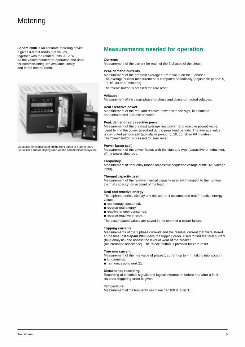
Measurements accessed on the front panel of Sepam 2000(serial links and/or display) and via the communication system.
6 Transformer
functions ranges accuracy (4)
ammeter (1) 0 to 24 In ±0,5%
peak demand current (1) 0 to 24 In ±0,5%
voltmeter (1) 0 to 1.5 Un ±0,5%
wattmeter (1) 0 to 999 MW ±1%
varmeter (1) 0 to 999 MVAr ±1%
peak demand real power (1) 0 to 999 MW ±1%
peak demand reactive power (1) 0 to 999 MVAr ±1%
power factor (1) (3) -1 to +1 0,01
frequency meter (1) 45 to 65 Hz ±0,02 Hz
accumulated real energy (1) 0 to 280.106 MWh ±1%
accumulated reactive energy (1) 0 to 280.106 MVArh ±1%
tripping currents (1) phase 0 to 24 In ±5%
earth 0 to 10 Ino ±5%
true rms current (2) 0 to 4 In ±1%up to rank 21
disturbance recording (5) record 86 periods 12 samplesduration per period
time before 1 to 85 periodstriggeringevent
thermal capacity used (6) 0 to 999% ±2%
temperature (1) -50 ° to 250 °C ±1 °Cresidual current (6) 0 to 10 Ino ±5%
residual voltage (6) 0 to 1.5 Un ±5%
cumulative breaking current (6) 0 to 9999 (kA)2 ±10%
number of breaks (6) 0 to 99999
Characteristics
(1) measurement accessed on the front panel of Sepam 2000 (display and serial link) and viathe communication system.(2) measurement accessed on the front panel of Sepam 2000 (serial link).(3) capacitive or inductive(4) typical accuracy with nominal values according to IEC 60255-6.(5) transfer of records to the front panel of Sepam 2000 using the SFT2801 software programand via Jbus/Modbus communication.(6) measurement accessed on front panel of Sepam 2000 (serial link) and via thecommunication system.
Reminder:Rated current In, rated voltage Un and current Ino are general parameters that are setat the time of Sepam 2000 commissioning.In is the current sensor rated current (CT rating).Ino is the core balance CT rating.Un is the rated phase-to-phase voltage of the voltage sensor primary windings.
Metering (cont'd)
Measurements usedfor commissioningand maintenance
Residual current / residual voltageUsed to check the current and voltage sensorconnections by giving the measurement of:c the residual current used for the earth faultprotection function,c the residual voltage used for the neutral voltagedisplacement and the directional earth fault protectionfunctions.
Cumulative breaking currentand number of breaksUsed for breaking device maintenance.
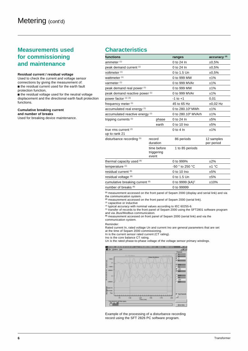
Example of the processing of a disturbance recordingrecord using the SFT 2826 PC software program.
7Transformer
Protection
Thermal overload (ANSI 49) F431*Protection of equipment against thermal damagecaused by overloads. Thermal overload is calculatedaccording to a mathematical model, with 2 timeconstants (T1 and T2), taking into account harmonicsup to rank 21st and the effect of negative sequencecurrent by means of an adjustable weightingcoefficient.
The function comprises:c an adjustable alarm setting,c an adjustable trip setting.
Recommendations (for transformer protection):c use the same setting for T1 and T2(heating and cooling time constants),c set the negative sequence/unbalancecoeffecient to zero.
Phase overcurrent (ANSI 50/51) F011 to F014*Three-phase connection and equipment protectionagainst phase-to-phase faults.The following types of time delay settings areavailable: definite, standard inverse, very inverse,extremely inverse or ultra inverse.
Earth fault(ANSI 50N/51N or 50G/51G) F081 to F084*Connection and equipment earth fault protection.The following types of time delay can be:definite, standard inverse, very inverse, extremelyinverse or ultra inverse.Residual current detection can be provided by:c the three phase current transformers ,in which case a harmonic 2 restraint is used to doaway with transformer closing related tripping.c a current transformer (1or 5A), combined with aCSH30 interposing ring CT,c a CSH120 or CSH200 core balance CT, accordingto the required diameter, this method being the mostaccurate one.The two ratings available (2 and 30A), provide a verywide setting range,c a diferent core balance CT, associated with anadapter ACE990.
Neutral voltage displacement (ANSI 59N) F391*Detection of insulation faults in ungrounded systemsby measurement of neutral voltage displacement.This protection function is generally used fortransformer incomers or busbars.
Directional overcurrent (ANSI 67) F521*Incomer protection, which provides quick, selectiveprotection against upstream faults when there areseveral parallel transformer incomers in the network.
Directional earth fault (ANSI 67N) F501*This protection function has several uses:c highly sensitive earth fault protection for transformerfeeders supplied by long cables characterized by highcapacitive current,c quick, selective detection of upstream earth faultswhen there are several parallel transformers in thenetwork.
Tank earth leakage (ANSI 50/51) F021*Quick, selective detection of earth leakage current in transformer primary andsecondary windings.This overcurrent protection is combined with a current sensor installed on the tankearthing connection.It requires isolation of the transformer tank.
Thermostat, BuchholzTransformer protection against temperature rise and internal fault from contactsdelivered by integrated devices.
Neutral (ANSI 50/51N) F091, F092*Overload protection of neutral earthing impedance and sensitive overall networkprotection against earth faults.This overcurrent protection is combined with a current sensor installedon the neutral earthing connection.This protection can be made insensitive to harmonic 2.
Undervoltage (ANSI 27) F321, F341, F361Protection used either for automated functions (changeover, load shedding)or for the protection of several motors against undervoltage.This protection monitors each of the line to line voltages measured.
Remanent undervoltage (ANSI 27R) F351*Monitoring of the clearing of voltage sustained by rotating machines afterthe opening of the circuit.This protection is used with automatic changeover functions to prevent transientelectrical and mechanical phenomena that are caused by fast resupply of powerto motors. It monitors line to line voltage U21.
Overvoltage (ANSI 59) F301, F302*Protection against abnormally high voltage and checking that there is sufficientvoltage for power supply changeover.This protection monitors line to line voltage U21.
Temperature monitoring (RTDs) (ANSI 36/49T) F461...F466*Protection which detects abnormal temperature rise in transformers equippedwith Pt100 type platinum resistor RTDs.The protection manages 2 independent, adjustable set points for each RTD:c 1 alarm setting,c 1 tripping setting.The RTD cabling is continuously monitored.
Restricted earth fault (ANSI 64REF) F651*Protection against phase-to-earth faults in three-phase windings with earthedneutral.
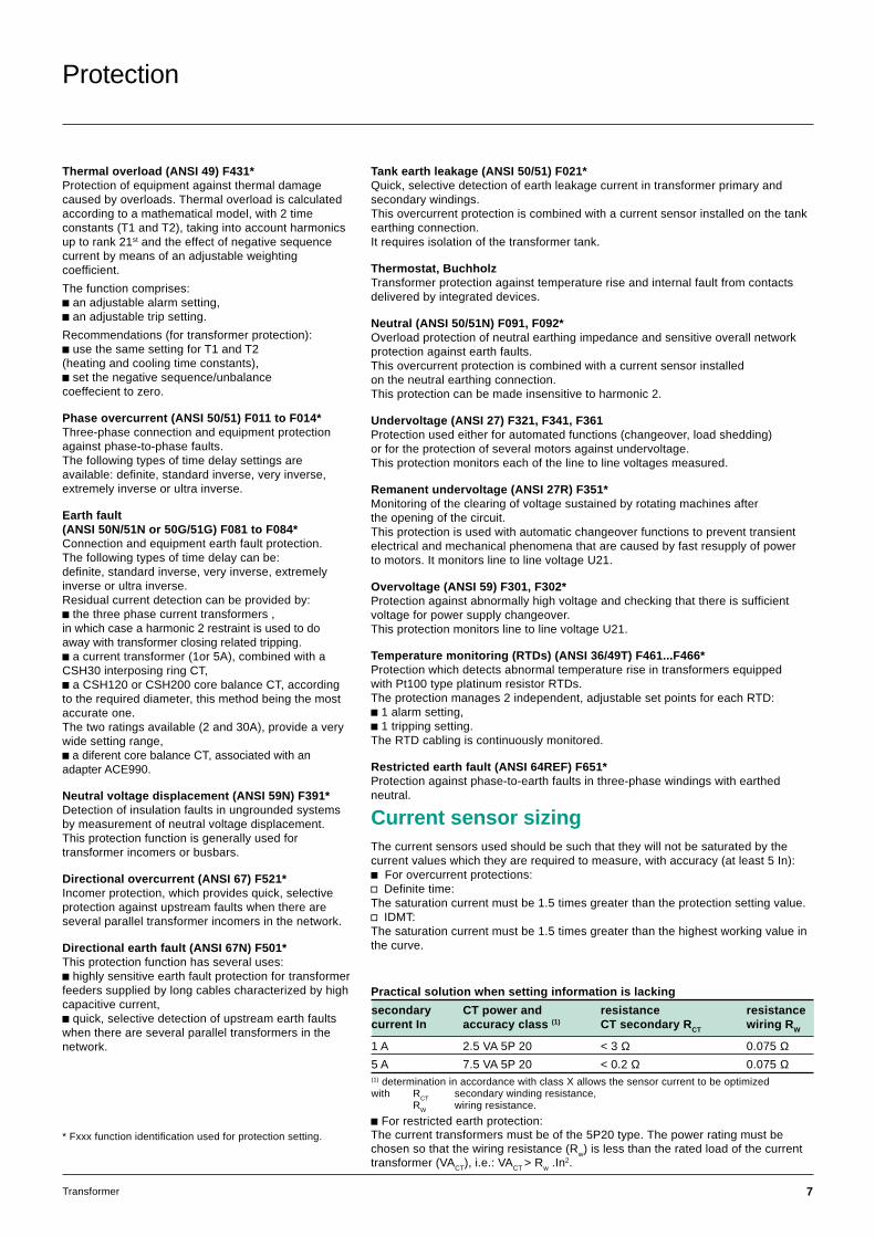
Current sensor sizingThe current sensors used should be such that they will not be saturated by thecurrent values which they are required to measure, with accuracy (at least 5 In):c For overcurrent protections:v Definite time:The saturation current must be 1.5 times greater than the protection setting value.v IDMT:The saturation current must be 1.5 times greater than the highest working value inthe curve.
* Fxxx function identification used for protection setting.
secondary CT power and resistance resistancecurrent In accuracy class (1) CT secondary RCT wiring RW
1 A 2.5 VA 5P 20 < 3 Ω 0.075 Ω5 A 7.5 VA 5P 20 < 0.2 Ω 0.075 Ω(1) determination in accordance with class X allows the sensor current to be optimizedwith R
CTsecondary winding resistance,
RW wiring resistance.
Practical solution when setting information is lacking
c For restricted earth protection:The current transformers must be of the 5P20 type. The power rating must bechosen so that the wiring resistance (Rw) is less than the rated load of the currenttransformer (VACT), i.e.: VACT > Rw .In2.
8 Transformer
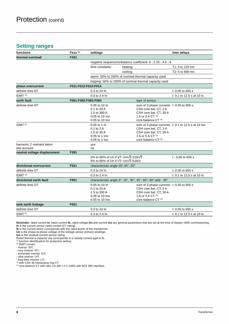
Setting rangesfunctions Fxxx (1) settings time delays
thermal overload F431
negative sequence/unbalance coefficient: 0 ; 2.25 ; 4.5 ; 9
time constants: heating T1: 5 to 120 mn
cooling T2: 5 to 600 mn
alarm: 50% to 200% of nominal thermal capacity used
tripping: 50% to 200% of nominal thermal capacity used
phase overcurrent F011-F012-F013-F014
definite time DT 0.3 to 24 In t: 0.05 to 655 s
IDMT (2) 0.3 to 2.4 In t: 0.1 to 12.5 s at 10 Is
earth fault F081-F082-F083-F084 type of sensor
definite time DT 0.05 to 10 In sum of 3 phase currents t: 0.05 to 655 s0.1 to 20 A CSH core bal. CT, 2 A1.5 to 300 A CSH core bal. CT, 30 A0.05 to 10 Ino 1 A or 5 A CT (3)
0.05 to 10 Ino core balance CT (4)
IDMT (2) 0.05 to 1 In sum of 3 phase currents t: 0.1 to 12.5 s at 10 Iso0.1 to 2 A CSH core bal. CT, 2 A1.5 to 30 A CSH core bal. CT, 30 A0.05 to 1 Ino 1 A or 5 A CT (3)
0.05 to 1 Ino core balance CT (4)
harmonic 2 restraint taken yesinto account noneutral voltage displacement F391
2% to 80% of Un if VT: Un/e/100/e t : 0,05 to 655 s5% to 80% of Un if VT: Un/e/100/3
directional overcurrent F521 characteristic angle 30°,45°, 60°definite time DT 0.3 to 24 In t: 0.05 to 655 s
IDMT (2) 0.3 to 2.4 In t: 0.1 to 12.5 s at 10 Is
directional earth fault F501 characteristic angle 0°, 15°, 30°, 45°, 60°, 90° and - 45°definite time DT 0.05 to 10 In sum of 3 phase currents t: 0.05 to 655 s
0.1 to 20 A CSH core bal. CT, 2 A1.5 to 300 A CSH core bal. CT, 30 A0.05 to 10 Ino 1 A or 5 A CT (3)
0.05 to 10 Ino core balance CT (4)
tank earth leakage F021
definite time DT 0.3 to 24 In t: 0.05 to 655 s
IDMT (2) 0.3 to 2.4 In t: 0.1 to 12.5 s at 10 Is
Reminder: rated current In, basis current Ib, rated voltage Un and current Ino are general parameters that are set at the time of Sepam 2000 commissioning.In is the current sensor rated current (CT rating).Ib is the current which corresponds with the rated power of the transformer.Un is the phase-to-phase voltage of the voltage sensor primary windings.Ino is the residual current sensor rating.Rated thermal a capacity use corresponds to a steady current egal to Ib.(1) function identification for protection setting.(2) IDMT curves:- inverse: SIT,- very inverse: VIT,- extremely inverse: EIT,- ultra inverse: UIT,- long time inverse: LTI.(3) with CSH 30 interposing ring CT.(4) core balance CT with ratio 1/n (50 i n i 1500) with ACE 990 interface.
Protection (cont'd)
9Transformer
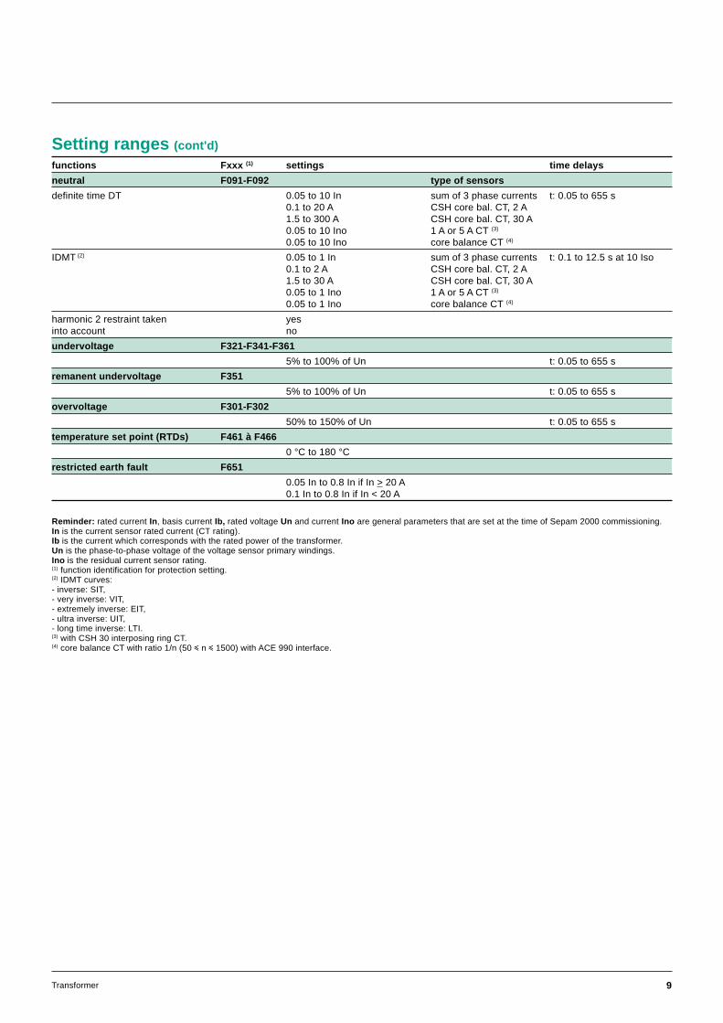
functions Fxxx (1) settings time delays
neutral F091-F092 type of sensors
definite time DT 0.05 to 10 In sum of 3 phase currents t: 0.05 to 655 s0.1 to 20 A CSH core bal. CT, 2 A1.5 to 300 A CSH core bal. CT, 30 A0.05 to 10 Ino 1 A or 5 A CT (3)
0.05 to 10 Ino core balance CT (4)
IDMT (2) 0.05 to 1 In sum of 3 phase currents t: 0.1 to 12.5 s at 10 Iso0.1 to 2 A CSH core bal. CT, 2 A1.5 to 30 A CSH core bal. CT, 30 A0.05 to 1 Ino 1 A or 5 A CT (3)
0.05 to 1 Ino core balance CT (4)
harmonic 2 restraint taken yesinto account no
undervoltage F321-F341-F361
5% to 100% of Un t: 0.05 to 655 s
remanent undervoltage F351
5% to 100% of Un t: 0.05 to 655 s
overvoltage F301-F302
50% to 150% of Un t: 0.05 to 655 s
temperature set point (RTDs) F461 à F466
0 °C to 180 °Crestricted earth fault F651
0.05 In to 0.8 In if In > 20 A0.1 In to 0.8 In if In < 20 A
Reminder: rated current In, basis current Ib, rated voltage Un and current Ino are general parameters that are set at the time of Sepam 2000 commissioning.In is the current sensor rated current (CT rating).Ib is the current which corresponds with the rated power of the transformer.Un is the phase-to-phase voltage of the voltage sensor primary windings.Ino is the residual current sensor rating.(1) function identification for protection setting.(2) IDMT curves:- inverse: SIT,- very inverse: VIT,- extremely inverse: EIT,- ultra inverse: UIT,- long time inverse: LTI.(3) with CSH 30 interposing ring CT.(4) core balance CT with ratio 1/n (50 i n i 1500) with ACE 990 interface.
Setting ranges (cont'd)
10 Transformer
Control and monitoring
Open / close controlUsed to control breaking devices equiped withdifferent types of opening and closing coils:c circuit breaker with shunt-trip or undervoltagerelease coil,c latching contactor with shunt-trip coil.Parameter setting via the TSM2001 pocket terminal,or PC softwares SFT 2801 or SFT 2821, allows thelogic to be adapted to suit the equipment being used(by default, the logic is adapted for control of a circuitbreaker with a shunt-trip coil).
The opening order (via input I13) differs accordingto the programmed type of control:c normally open contact for shunt trip coil (circuitbreaker or contactor with latched order control),c normally closed contact for undervoltage releasecoil (circuit breaker).
Lockout relay (ANSI 86)Stores tripping orders (lockout) and requires useraction to be put back into operation (reset).
Inhibit closing (ANSI 69)Inhibits the closing of the circuit breaker or thecontactor according to operating conditions.
Annunciation (ANSI 30)Keeps the user informed by the display of messages.
Thermostat, BuchholzAlarm, and tripping from contacts delivered byintegrated devices.
IntertrippingUsed for intertripping of the Sepams upstream anddownstream from the transformer when faults aredetected by the protections:c neutral voltage displacement,c tank earth leakage,c neutral,and by external devices:c Buchholz,c gas and pressure detector.
Logic discrimination (ANSI 68)Enables quick, selective tripping of the phase overcurrent and earth fault protectionrelays, whether definite time (DT) or IDMT (standard inverse SIT, very inverse VIT,extremely inverse EIT or ultra inverse UIT). The function triggers the transmissionof a "blocking input" signal whenever one of the protection settings is exceeded.
Blocking input signal transmission can be used by the Sepam Logic discriminationfunction for substation, alternator, transformer and busbar connection applications.
Trip circuit supervision and discrepancy (ANSI 74)Detects tripping (by shunt-trip coil) circuit faults. Can be used when theSepam 2000 and the tripping auxiliary power sources have the same voltage rating.
If the equipment contains an undervoltage release coil only, the tripping circuit isnot supervised since it is fail-safe. This function can also detect positioninformation discrepancies (neither open nor closed or simultaneously open andclosed) in the different control schemes. The connection of inputs I1, I2 and tripoutput O1 on the ESB board must be respected (see other connection schemes).
Detection of plugged connectors (ANSI 74)Indication on the display unit that one or more connectors are not plugged in(the DPC terminals must be connected: see connection schemes).
Three-pole undervoltage protection function (ANSI 27)Three-pole undervoltage protection function is a "or" between the single-poleundervoltage protection functions: U13 undervoltage or U21 undervoltage or U32undervoltage.
Operation counter (1)
Counts the number of closing operations made by the breaking device, therebyfacilitating equipment maintenance.
Phase fault trip counter (1)
Counts the number of operations for which breaking performances were required,thereby facilitating equipment maintenance.
Disturbance recording triggeringTriggers recording of electrical signals and logical states by:c voluntary local or remote action,c instantaneous overcurrent, earth fault, directional phase overcurrent, directionalearth fault, tank earth leakage, neutral and restricted earth fault protections,c protection tripping order.
(1) counter reading is via serial link on the front panel of Sepam 2000, and via Jbus/Modbuscommunication.
11Transformer
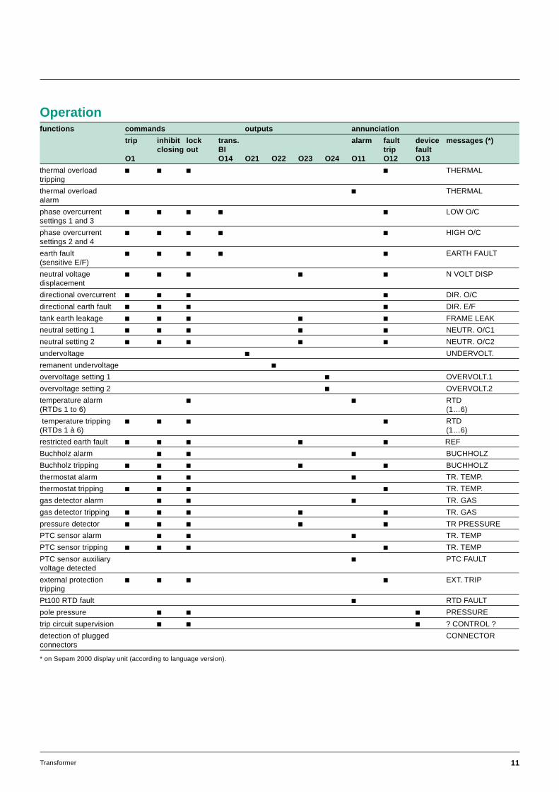
functions commands outputs annunciation
trip inhibit lock trans. alarm fault device messages (*)closing out BI trip fault
O1 O14 O21 O22 O23 O24 O11 O12 O13
thermal overload c c c c THERMALtripping
thermal overload c THERMALalarm
phase overcurrent c c c c c LOW O/Csettings 1 and 3
phase overcurrent c c c c c HIGH O/Csettings 2 and 4
earth fault c c c c c EARTH FAULT(sensitive E/F)
neutral voltage c c c c c N VOLT DISPdisplacement
directional overcurrent c c c c DIR. O/C
directional earth fault c c c c DIR. E/F
tank earth leakage c c c c c FRAME LEAK
neutral setting 1 c c c c c NEUTR. O/C1
neutral setting 2 c c c c c NEUTR. O/C2
undervoltage c UNDERVOLT.
remanent undervoltage covervoltage setting 1 c OVERVOLT.1
overvoltage setting 2 c OVERVOLT.2
temperature alarm c c RTD(RTDs 1 to 6) (1…6)
temperature tripping c c c c RTD(RTDs 1 à 6) (1…6)
restricted earth fault c c c c c REF
Buchholz alarm c c c BUCHHOLZ
Buchholz tripping c c c c c BUCHHOLZ
thermostat alarm c c c TR. TEMP.
thermostat tripping c c c c TR. TEMP.
gas detector alarm c c c TR. GAS
gas detector tripping c c c c c TR. GAS
pressure detector c c c c c TR PRESSURE
PTC sensor alarm c c c TR. TEMP
PTC sensor tripping c c c c TR. TEMP
PTC sensor auxiliary c PTC FAULTvoltage detected
external protection c c c c EXT. TRIPtripping
Pt100 RTD fault c RTD FAULT
pole pressure c c c PRESSURE
trip circuit supervision c c c ? CONTROL ?
detection of plugged CONNECTORconnectors
Operation
* on Sepam 2000 display unit (according to language version).
12 Transformer
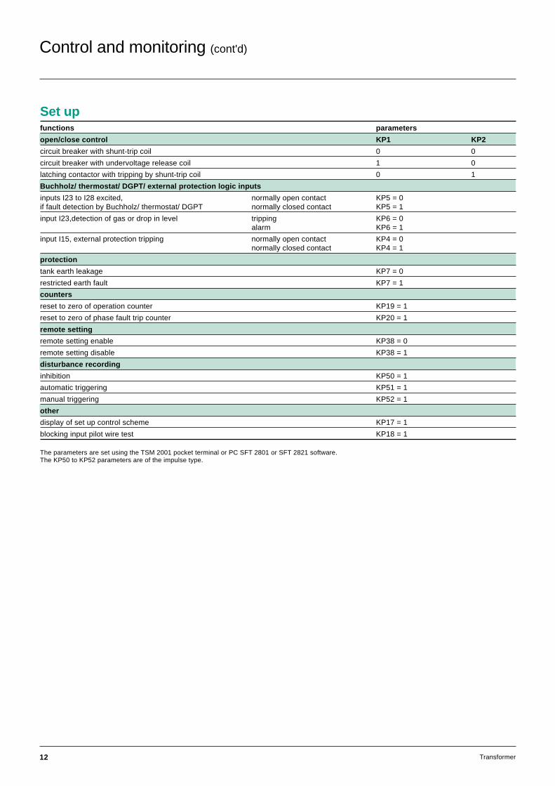
functions parameters
open/close control KP1 KP2
circuit breaker with shunt-trip coil 0 0
circuit breaker with undervoltage release coil 1 0
latching contactor with tripping by shunt-trip coil 0 1
Buchholz/ thermostat/ DGPT/ external protection logic inputs
inputs I23 to I28 excited, normally open contact KP5 = 0if fault detection by Buchholz/ thermostat/ DGPT normally closed contact KP5 = 1
input I23,detection of gas or drop in level tripping KP6 = 0alarm KP6 = 1
input I15, external protection tripping normally open contact KP4 = 0normally closed contact KP4 = 1
protection
tank earth leakage KP7 = 0
restricted earth fault KP7 = 1
counters
reset to zero of operation counter KP19 = 1
reset to zero of phase fault trip counter KP20 = 1
remote setting
remote setting enable KP38 = 0
remote setting disable KP38 = 1
disturbance recording
inhibition KP50 = 1
automatic triggering KP51 = 1
manual triggering KP52 = 1
other
display of set up control scheme KP17 = 1
blocking input pilot wire test KP18 = 1
The parameters are set using the TSM 2001 pocket terminal or PC SFT 2801 or SFT 2821 software.The KP50 to KP52 parameters are of the impulse type.
Set up
Control and monitoring (cont'd)
13Transformer
Functional and connection schemes
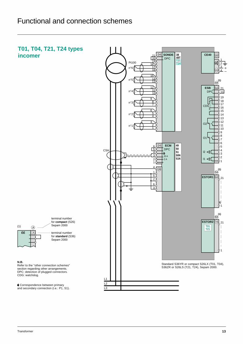
T01, T04, T21, T24 typesincomer
L1
L2
L3
CE40 1B
1A 4
23
1DPC2021
1918
1716
SONDE3A
n°6
151413n°5
121110
n°4
987
n°3
654
n°2
321
n°1
Pt100
3849TT21T24
ECM56
432
2A
30 A
DPC
2 A
1
4
52
63
2B
49505150N51N
ESB 5A
DPC
O2
O1
l2
l1
CDG
2120
19
1716
131211
5
10
1415
18
76
4
2
98
3
1
6A(1)
5A(1)
6A(1)
21
1
6AESTOR1
21
1
7AESTOR2
1
4A(1)
T01T21
CSH
Standard S36YR or compact S26LX (T01, T04),S36ZR or S26LS (T21, T24), Sepam 2000.
N.B.Refer to the "other connection schemes"section regarding other arrangements.DPC: detection of plugged connectors.CDG: watchdog.
c Correspondence between primaryand secondary connection (i.e.: P1, S1).
(1)
.AÉÉ
.A
terminal numberfor compact (S26)Sepam 2000
terminal numberfor standard (S36)Sepam 2000

14 Transformer
Functional and connection schemes (cont’d)
T01, T04, T21, T24 typesfeeder
Standard S36YR or compact S26LX (T01, T04),S36ZR or S26LS (T21, T24), Sepam 2000.
L1
L2
L3
CE40 1B
1A 4
23
1
ESB 5A
DPC
O2
O1
l2
l1
CDG
2120
19
1716
131211
5
10
1415
18
76
4
2
98
3
1
14
52
63
56
4321
2A
DPC
ECM2B
DPC
30 A2 A
21
1
6AESTOR1
21
1
7AESTOR2
5A(1)
6A(1)
49505150N51N
4A(1)
DPC2021
1918
1716
SONDE3A
n°6
151413
n°5
121110
n°4
987
n°3
654
n°2
321
n°1
Pt100
3849TT21T24
T01T21
CSH
N.B.Refer to the "other connection schemes"section regarding other arrangements.DPC: detection of plugged connectors.CDG: watchdog.
(1)
c Correspondence between primaryand secondary connection (i.e.: P1, S1).
.AÉÉ
.A
terminal numberfor compact (S26)Sepam 2000
terminal numberfor standard (S36)Sepam 2000
15Transformer
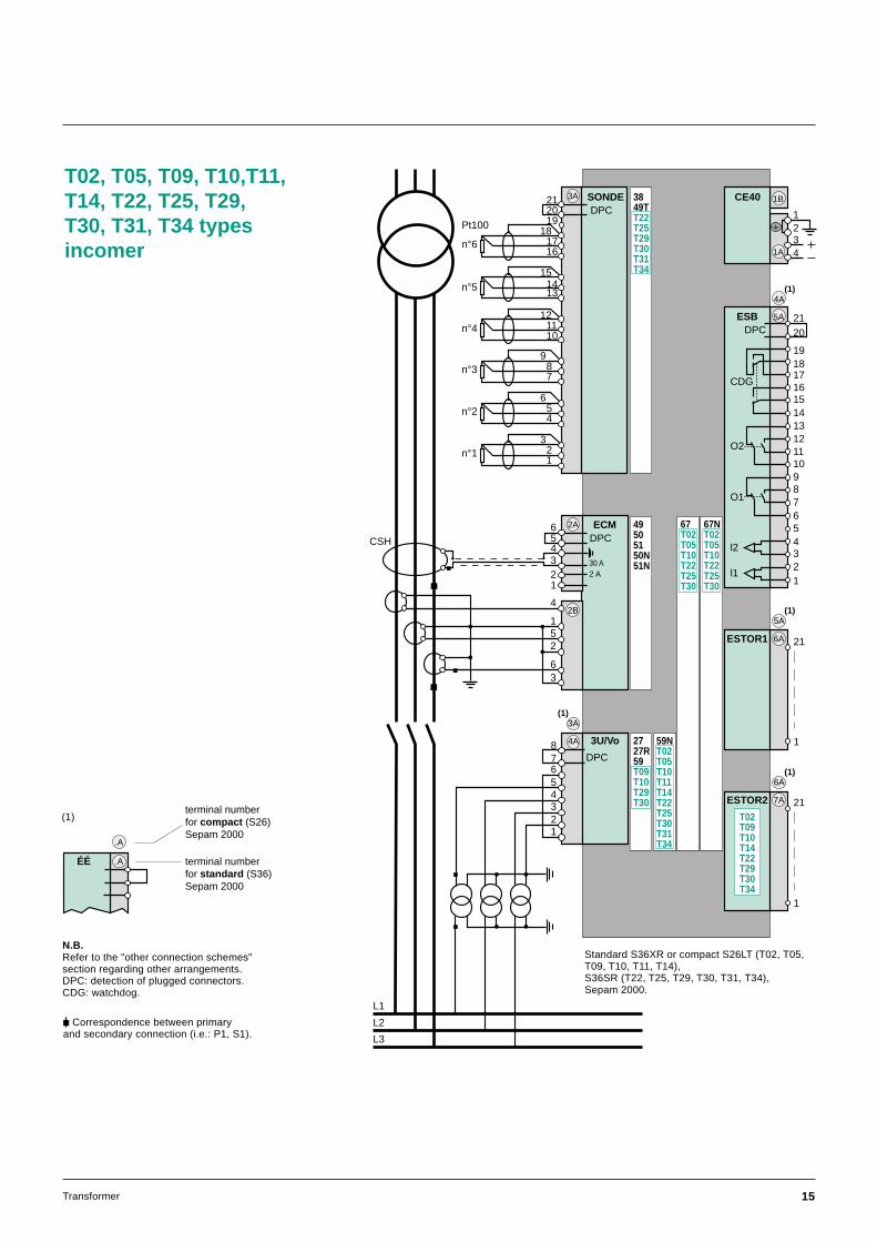
T02, T05, T09, T10,T11,T14, T22, T25, T29,T30, T31, T34 typesincomer
L1
L2
L3
CE40 1B
1A 4
23
1
ECM56
432
2A
30 A
DPC
2 A
ESB 5A
DPC
O2
O1
l2
l1
CDG
2120
19
1716
131211
5
10
1415
18
76
4
2
98
3
1
5A(1)
6A(1)
4A 3U/Vo
56
4321
78
DPC
21
1
6AESTOR1
21
1
7AESTOR2
DPC2021
1918
1716
SONDE3A
n°6
151413n°5
121110
n°4
987
n°3
654
n°2
321
n°1
Pt100
3849TT22T25T29T30T31T34
2727R59T09T10T29T30
49505150N51N
59NT02T05T10T11T14T22T25T30T31T34
67T02T05T10T22T25T30
67NT02T05T10T22T25T301
4A(1)
3A(1)
T02T09T10T14T22T29T30T34
1
4
52
63
2B
CSH
N.B.Refer to the "other connection schemes"section regarding other arrangements.DPC: detection of plugged connectors.CDG: watchdog.
c Correspondence between primaryand secondary connection (i.e.: P1, S1).
Standard S36XR or compact S26LT (T02, T05,T09, T10, T11, T14),S36SR (T22, T25, T29, T30, T31, T34),Sepam 2000.
(1)
.AÉÉ
.A
terminal numberfor compact (S26)Sepam 2000
terminal numberfor standard (S36)Sepam 2000

16 Transformer
T09, T11, T16, T17, T19,T29, T31, T36, T37, T39 typesfeeder
L1
L2
L3
CE40 1B
1A 4
23
1
ESB 5A
DPC
O2
O1
l2
l1
CDG
2120
19
1716
131211
5
10
1415
18
76
4
2
98
3
1
14
52
63
56
4321
2A
DPC
ECM2B
DPC
30 A2 A
21
1
6AESTOR1
21
1
7AESTOR2
4A 3U/Vo
56
4321
78
DPC
5A(1)
6A(1)
DPC2021
1918
1716
SONDE3A
n°6
151413
n°5
121110
n°4
987
n°3
654
n°2
321
n°1
Pt100
3849TT29T31T36T37T39
49505150N51N
59NT11T19T31T39
2727R59T09T19T29T39
67NT16T17T19T36T37T39
3A(1)
T09T17T19T29T37T39
4A(1)
CSH
N.B.Refer to the "other connection schemes"section regarding other arrangements.DPC: detection of plugged connectors.CDG: watchdog.
c Correspondence between primaryand secondary connection (i.e.: P1, S1).
Functional and connection schemes (cont’d)
Standard S36XR or compact S26LT(T09, T11, T16, T17, T19),S36SR (T29, T31, T36, T37, T39), Sepam 2000.
.AÉÉ
.A
terminal numberfor compact (S26)Sepam 2000
terminal numberfor standard (S36)Sepam 2000
17Transformer
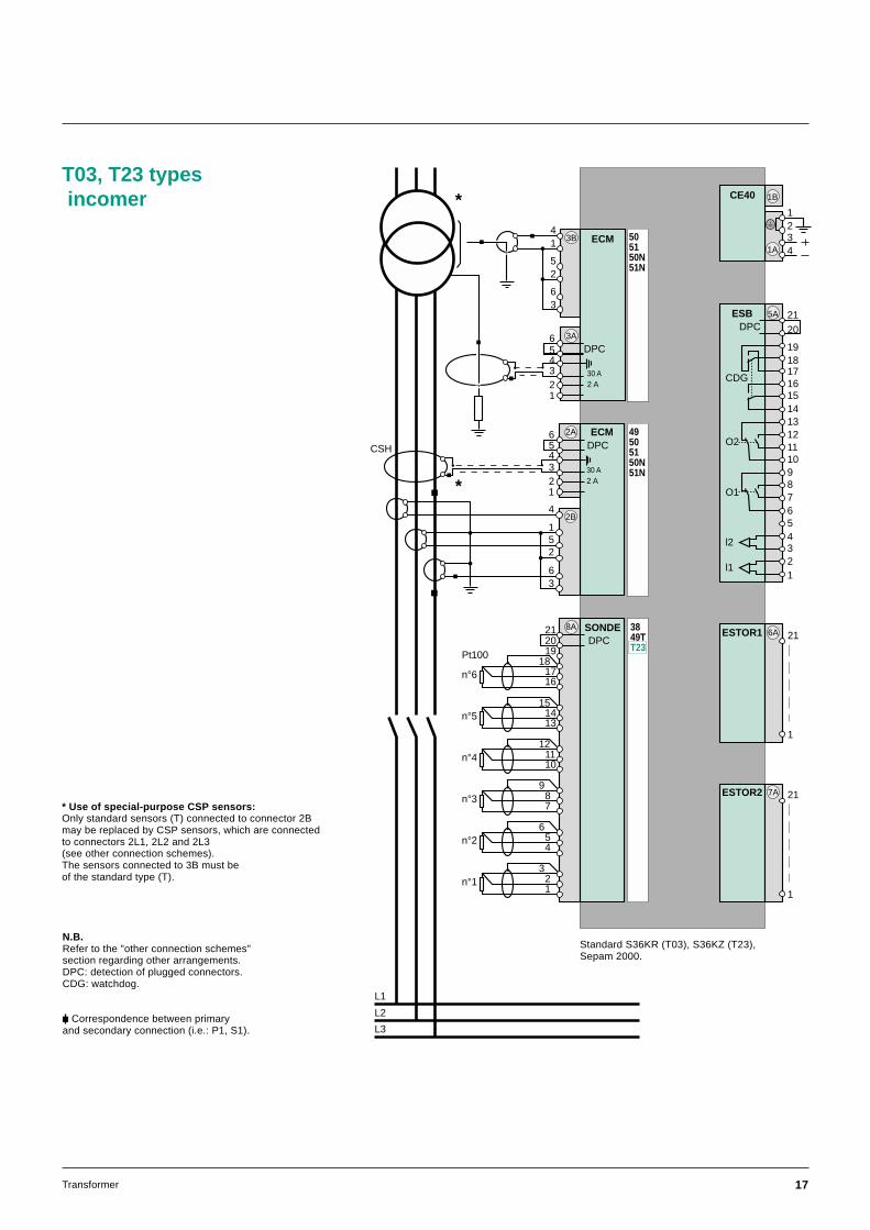
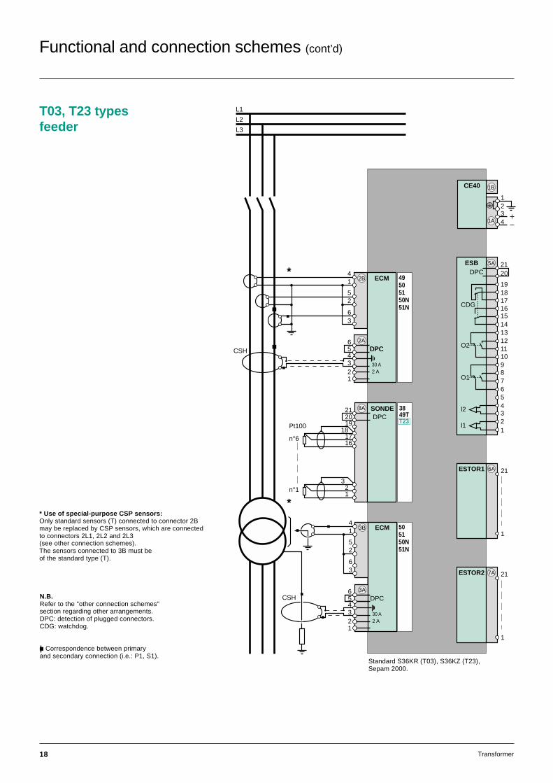
T03, T23 types incomer
L1
L2
L3
CE40 1B
1A 4
23
1
ESB 5A
DPC
O2
O1
l2
l1
CDG
2120
19
1716
131211
5
10
1415
18
76
4
2
98
3
1
21
1
6AESTOR1
21
1
7AESTOR2
14
52
63
3A
DPC
ECM3B 505150N51N
56
4321
30 A2 A
ECM56
432
2A
30 A
DPC
2 A
49505150N51N
*
*
DPC2021
1918
1716
SONDE8A
n°6
151413
n°5
121110
n°4
987
n°3
654
n°2
321
n°1
Pt100
3849TT23
1
1
4
52
63
2B
CSH
N.B.Refer to the "other connection schemes"section regarding other arrangements.DPC: detection of plugged connectors.CDG: watchdog.
c Correspondence between primaryand secondary connection (i.e.: P1, S1).
Standard S36KR (T03), S36KZ (T23),Sepam 2000.
* Use of special-purpose CSP sensors:Only standard sensors (T) connected to connector 2Bmay be replaced by CSP sensors, which are connectedto connectors 2L1, 2L2 and 2L3(see other connection schemes).The sensors connected to 3B must beof the standard type (T).
18 Transformer
T03, T23 typesfeeder
14
52
63
L1
L2
L3
CE40 1B
1A 4
23
1
ESB 5A
DPC
O2
O1
l2
l1
CDG
2120
19
1716
131211
5
10
1415
18
76
4
2
98
3
1
3A
DPC
ECM3B 505150N51N
56
4321
30 A2 A
14
52
63
56
4321
2A
DPC
ECM2B 49505150N51N
DPC
30 A2 A
DPC2021
1918
1716
SONDE8A
n°6
321
n°1
Pt100
3849TT23
21
1
6AESTOR1
21
1
7AESTOR2
*
*
CSH
CSHN.B.Refer to the "other connection schemes"section regarding other arrangements.DPC: detection of plugged connectors.CDG: watchdog.
c Correspondence between primaryand secondary connection (i.e.: P1, S1).
Standard S36KR (T03), S36KZ (T23),Sepam 2000.
* Use of special-purpose CSP sensors:Only standard sensors (T) connected to connector 2Bmay be replaced by CSP sensors, which are connectedto connectors 2L1, 2L2 and 2L3(see other connection schemes).The sensors connected to 3B must beof the standard type (T).
Functional and connection schemes (cont’d)
19Transformer
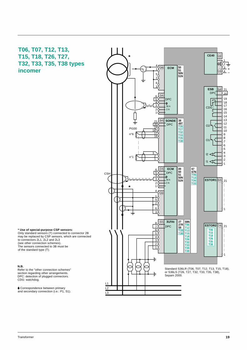
T06, T07, T12, T13,T15, T18, T26, T27,T32, T33, T35, T38 typesincomer
*
L1
L2
L3
CE40 1B
1A 4
23
1
ESB 5A
DPC
O2
O1
l2
l1
CDG
2120
19
1716
131211
5
10
1415
18
76
4
2
98
3
1
21
1
6AESTOR1
21
1
7AESTOR2
14
52
63
3A
DPC
ECM3B 505150N51N
56
4321
30 A2 A
ECM56
432
2A
30 A
DPC
2 A
49505150N51N
*
DPC2021
1918
1716
SONDE8A
n°6
321
n°1
Pt100
3849TT26T27T32T33T35T38
4A 3U/Vo
56
4321
78
DPC
2727R59T18T38
6767NT06T13T26T33
1
59NT06T12T13T15T18T26T32T33T35T38
T06T15T18T26T35T38
1
4
52
63
2B
CSH
N.B.Refer to the "other connection schemes"section regarding other arrangements.DPC: detection of plugged connectors.CDG: watchdog.
c Correspondence between primaryand secondary connection (i.e.: P1, S1).
Standard S36LR (T06, T07, T12, T13, T15, T18),or S36LS (T26, T27, T32, T33, T35, T38),Sepam 2000.
* Use of special-purpose CSP sensors:Only standard sensors (T) connected to connector 2Bmay be replaced by CSP sensors, which are connectedto connectors 2L1, 2L2 and 2L3(see other connection schemes).The sensors connected to 3B must beof the standard type (T).
20 Transformer
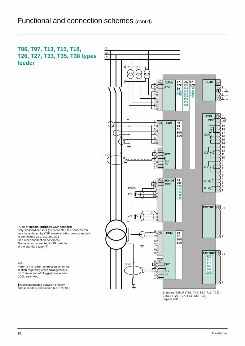
T06, T07, T13, T15, T18,T26, T27, T33, T35, T38 typesfeeder
14
52
63
L1
L2
L3
CE40 1B
1A 4
23
1
ESB 5A
DPC
O2
O1
l2
l1
CDG
2120
19
1716
131211
5
10
1415
18
76
4
2
98
3
1
3A
DPC
ECM3B
56
4321
30 A2 A
14
52
63
56
4321
2A
DPC
ECM2B
DPC
30 A2 A
DPC2021
1918
1716
SONDE8A
n°6
321
n°1
Pt100
3849TT26T27T33T35T38
21
1
6AESTOR1
21
1
7AESTOR2
*
*
505150N51N
49505150N51N
2727R59T18T38
59NT06T13T15T18T26T33T35T38
6767NT06T13T26T33
4A 3U/Vo
56
4321
78
DPC
T06T15T18T26T35T38
CSH
CSHN.B.Refer to the "other connection schemes"section regarding other arrangements.DPC: detection of plugged connectors.CDG: watchdog.
c Correspondence between primaryand secondary connection (i.e.: P1, S1).
Standard S36LR (T06, T07, T13, T15, T18),S36LS (T26, T27, T33, T35, T38),Sepam 2000.
* Use of special-purpose CSP sensors:Only standard sensors (T) connected to connector 2Bmay be replaced by CSP sensors, which are connectedto connectors 2L1, 2L2 and 2L3(see other connection schemes).The sensors connected to 3B must beof the standard type (T).
Functional and connection schemes (cont’d)

21Transformer
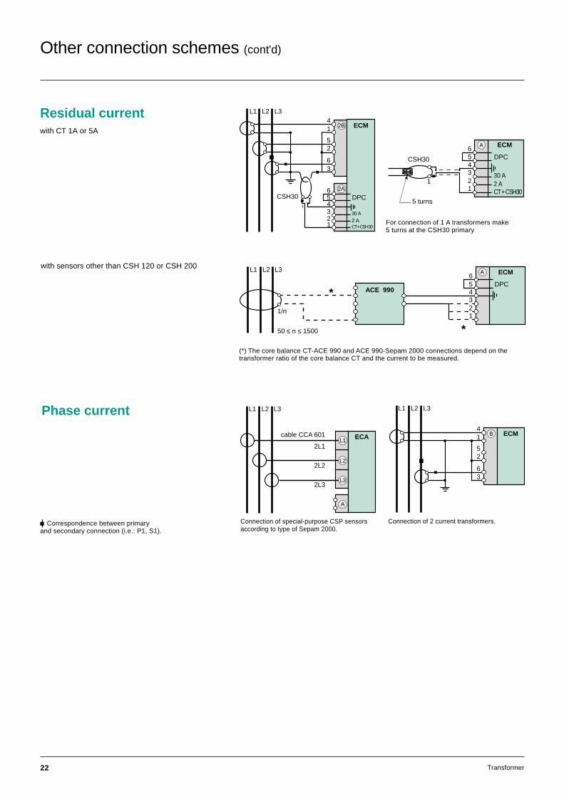
Other connection schemes
Phase and residual voltage
56
4321
3U/Vo
L1
L2
L3
78
DPC
A
Phase voltage
56
4321
3U/Vo
L1
L2
L3
78
DPC
A
56
4321
3U/Vo
L1
L2
L3
78
DPC
A
Broken delta connection of voltage transformers for residual voltage measurement.
Connection of a voltage transformer(does not allow implementation of the neutralvoltage displacement and directional earthfault protection functions or residual voltagemeasurement).
V - connection of 2 voltage transformers(does not allow implementation of the neutralvoltage displacement and directional earthfault protection functions or residual voltagemeasurement).
22 Transformer
Phase current
A
ECAcable CCA 601
L3
L2
L1
L1 L2 L3
2L1
2L2
2L3
14
52
63
ECMB
L1 L2 L3
Connection of 2 current transformers.Connection of special-purpose CSP sensorsaccording to type of Sepam 2000.
c Correspondence between primaryand secondary connection (i.e.: P1, S1).
Residual currentwith CT 1A or 5A
For connection of 1 A transformers make5 turns at the CSH30 primary
14
52
63
56
4321
2A
30 A
DPC
2 A
ECM2B
L1 L2 L3
CT + CSH 30
CSH30
56
4321
ECM
30 A
DPCP1
P2
S2
S1 2 ACT + CSH30
5 turns
A
1
CSH30
Other connection schemes (cont'd)
with sensors other than CSH 120 or CSH 200
(*) The core balance CT-ACE 990 and ACE 990-Sepam 2000 connections depend on thetransformer ratio of the core balance CT and the current to be measured.
ACE 990
L1 L2 L3
56
4321
ECM
DPC
A
*
*
1/n
50 ≤ n ≤ 1500
23Transformer
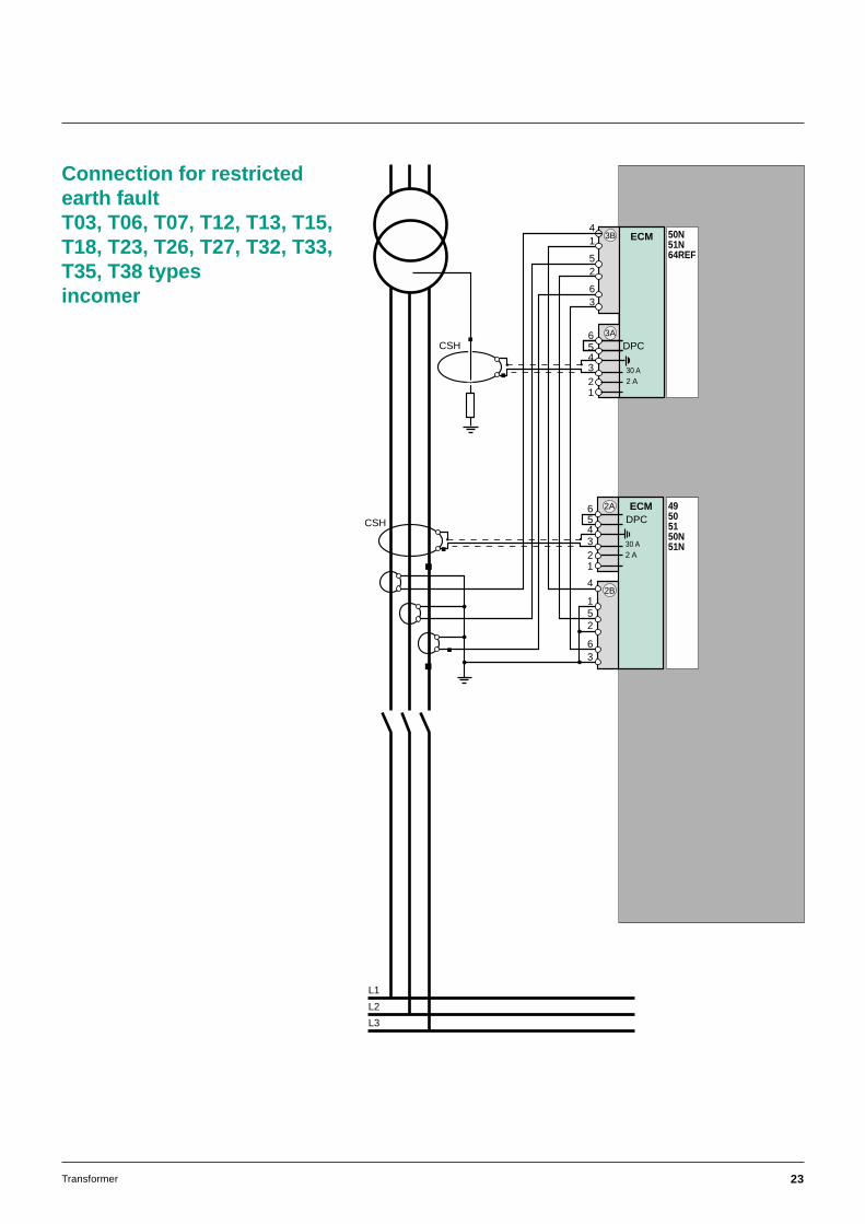
L1
L2
L3
14
52
63
3A
DPC
ECM3B 50N51N64REF
56
4321
30 A2 A
ECM56
432
2A
30 A
DPC
2 A
1
4
52
63
2B
49505150N51N
1
CSH
CSH
Connection for restrictedearth faultT03, T06, T07, T12, T13, T15,T18, T23, T26, T27, T32, T33,T35, T38 typesincomer
24 Transformer
Other connection schemes (cont’d)
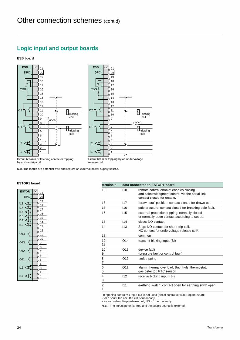
ESTOR1 board
ESTOR
DPC21
20
O11
7
4
3
2
1
l12
l11
8
5
6
10
9
12
11
O12
O13
O14
13
19
17
16
18
14
15
l13
l14l15
l16
l17
l18
A
terminals data connected to ESTOR1 board
19 I18 remote control enable: enables closingand acknowledgment control via the serial link:contact closed for enable.
18 I17 “drawn out” position: contact closed for drawn out.
17 I16 pole pressure: contact closed for breaking pole fault.
16 I15 external protection tripping: normally closedor normally open contact according to set up.
15 I14 close: NO contact
14 I13 Stop: NO contact for shunt-trip coil,NC contact for undervoltage release coil*.
13 common
12 O14 transmit bloking input (BI)11
10 O13 device fault9 (pressure fault or control fault)
8 O12 fault tripping7
6 O11 alarm: thermal overload, Buchholz, thermostat,5 gas detector, PTC sensor.
4 I12 receive bloking input (BI)3
2 I11 earthing switch: contact open for earthing swith open.1
* If opening control via input I13 is not used (direct control outside Sepam 2000):- for a shunt trip coil, I13 = 0 permanently.- for an undervoltage release coil, I13 = 1 permanently.
N.B. : The inputs potential-free and the supply source is external.
Circuit breaker or latching contactor trippingby a shunt-trip coil.
Circuit breaker tripping by an undervoltagerelease coil.
ESB board
N.B. The inputs are potential-free and require an external power supply source.
Logic input and output boards
ESB
DPC21
20
19
17
16
13
12
11
5
O2
10
14
15
18
O1
9
8
7
6
4
3
2
1
l2
l1
trippingcoil
open
closingcoil
CDG
A ESB
DPC21
20
19
17
16
13
12
11
5
O2
10
14
15
18
O1 7
6
4
3
2
1
l2
l1
CDG
9
8
A
closingcoil
trippingcoil
open
25Transformer
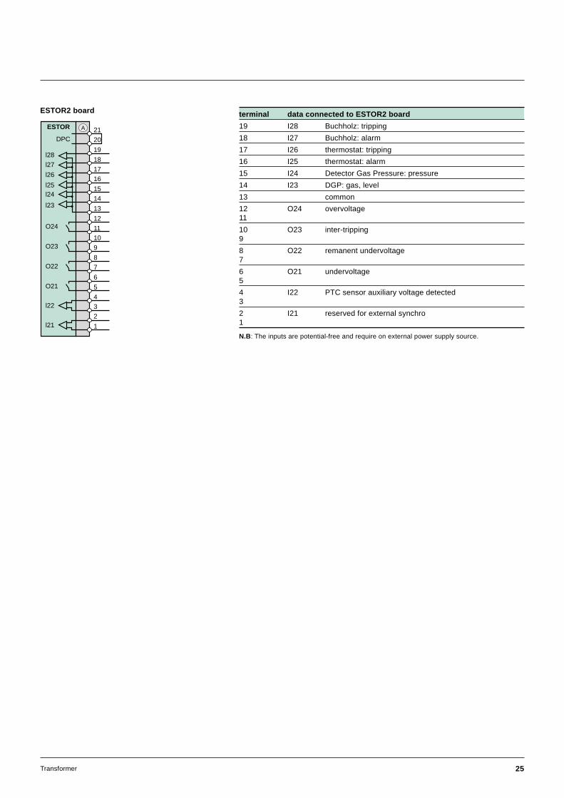
ESTOR2 board terminal data connected to ESTOR2 board
19 I28 Buchholz: tripping
18 I27 Buchholz: alarm
17 I26 thermostat: tripping
16 I25 thermostat: alarm
15 I24 Detector Gas Pressure: pressure
14 I23 DGP: gas, level
13 common
12 O24 overvoltage11
10 O23 inter-tripping9
8 O22 remanent undervoltage7
6 O21 undervoltage5
4 I22 PTC sensor auxiliary voltage detected3
2 I21 reserved for external synchro1
ESTOR
DPC21
20
O21
7
4
3
2
1
l22
l21
8
5
6
10
9
12
11
O22
O23
O24
13
19
17
16
18
14
15
l23
l24l25
l26
l27
l28
A
N.B: The inputs are potential-free and require on external power supply source.
26 Transformer
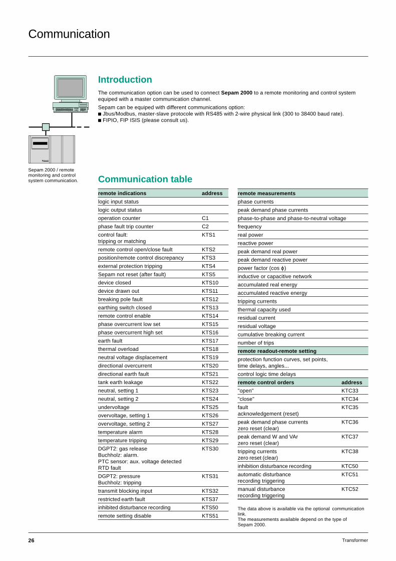
remote indications address
logic input status
logic output status
operation counter C1
phase fault trip counter C2
control fault: KTS1tripping or matching
remote control open/close fault KTS2
position/remote control discrepancy KTS3
external protection tripping KTS4
Sepam not reset (after fault) KTS5
device closed KTS10
device drawn out KTS11
breaking pole fault KTS12
earthing switch closed KTS13
remote control enable KTS14
phase overcurrent low set KTS15
phase overcurrent high set KTS16
earth fault KTS17
thermal overload KTS18
neutral voltage displacement KTS19
directional overcurrent KTS20
directional earth fault KTS21
tank earth leakage KTS22
neutral, setting 1 KTS23
neutral, setting 2 KTS24
undervoltage KTS25
overvoltage, setting 1 KTS26
overvoltage, setting 2 KTS27
temperature alarm KTS28
temperature tripping KTS29
DGPT2: gas release KTS30Buchholz: alarm.PTC sensor: aux. voltage detectedRTD fault
DGPT2: pressure KTS31Buchholz: tripping
transmit blocking input KTS32
restricted earth fault KTS37
inhibited disturbance recording KTS50
remote setting disable KTS51
Communication
Sepam 2000 / remotemonitoring and controlsystem communication.
MERLIN GERIN
Communication tableremote measurements
phase currents
peak demand phase currents
phase-to-phase and phase-to-neutral voltage
frequency
real power
reactive power
peak demand real power
peak demand reactive power
power factor (cos ϕ)
inductive or capacitive network
accumulated real energy
accumulated reactive energy
tripping currents
thermal capacity used
residual current
residual voltage
cumulative breaking current
number of trips
remote readout-remote setting
protection function curves, set points,time delays, angles...
control logic time delays
remote control orders address
"open" KTC33
"close" KTC34
fault KTC35acknowledgement (reset)
peak demand phase currents KTC36zero reset (clear)
peak demand W and VAr KTC37zero reset (clear)
tripping currents KTC38zero reset (clear)
inhibition disturbance recording KTC50
automatic disturbance KTC51recording triggering
manual disturbance KTC52recording triggering
The data above is available via the optional communicationlink.The measurements available depend on the type ofSepam 2000.
IntroductionThe communication option can be used to connect Sepam 2000 to a remote monitoring and control systemequiped with a master communication channel.
Sepam can be equiped with different communications option:c Jbus/Modbus, master-slave protocole with RS485 with 2-wire physical link (300 to 38400 baud rate).c FIPIO, FIP ISIS (please consult us).
27Transformer
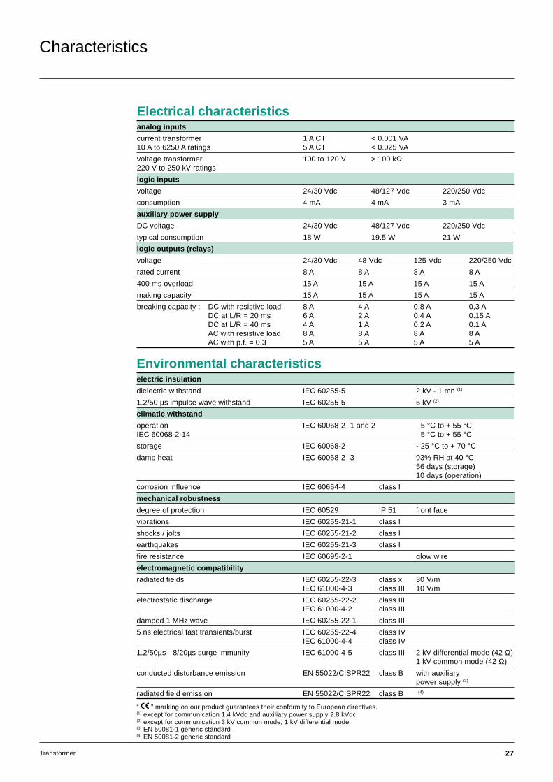
Characteristics
Electrical characteristicsanalog inputs
current transformer 1 A CT < 0.001 VA10 A to 6250 A ratings 5 A CT < 0.025 VA
voltage transformer 100 to 120 V > 100 kΩ220 V to 250 kV ratings
logic inputs
voltage 24/30 Vdc 48/127 Vdc 220/250 Vdc
consumption 4 mA 4 mA 3 mA
auxiliary power supply
DC voltage 24/30 Vdc 48/127 Vdc 220/250 Vdc
typical consumption 18 W 19.5 W 21 W
logic outputs (relays)
voltage 24/30 Vdc 48 Vdc 125 Vdc 220/250 Vdc
rated current 8 A 8 A 8 A 8 A
400 ms overload 15 A 15 A 15 A 15 A
making capacity 15 A 15 A 15 A 15 A
breaking capacity : DC with resistive load 8 A 4 A 0,8 A 0,3 ADC at L/R = 20 ms 6 A 2 A 0.4 A 0.15 ADC at L/R = 40 ms 4 A 1 A 0.2 A 0.1 AAC with resistive load 8 A 8 A 8 A 8 AAC with p.f. = 0.3 5 A 5 A 5 A 5 A
Environmental characteristicselectric insulation
dielectric withstand IEC 60255-5 2 kV - 1 mn (1)
1.2/50 µs impulse wave withstand IEC 60255-5 5 kV (2)
climatic withstand
operation IEC 60068-2- 1 and 2 - 5 °C to + 55 °CIEC 60068-2-14 - 5 °C to + 55 °Cstorage IEC 60068-2 - 25 °C to + 70 °Cdamp heat IEC 60068-2 -3 93% RH at 40 °C
56 days (storage)10 days (operation)
corrosion influence IEC 60654-4 class I
mechanical robustness
degree of protection IEC 60529 IP 51 front face
vibrations IEC 60255-21-1 class I
shocks / jolts IEC 60255-21-2 class I
earthquakes IEC 60255-21-3 class I
fire resistance IEC 60695-2-1 glow wire
electromagnetic compatibility
radiated fields IEC 60255-22-3 class x 30 V/mIEC 61000-4-3 class III 10 V/m
electrostatic discharge IEC 60255-22-2 class IIIIEC 61000-4-2 class III
damped 1 MHz wave IEC 60255-22-1 class III
5 ns electrical fast transients/burst IEC 60255-22-4 class IVIEC 61000-4-4 class IV
1.2/50µs - 8/20µs surge immunity IEC 61000-4-5 class III 2 kV differential mode (42 Ω)1 kV common mode (42 Ω)
conducted disturbance emission EN 55022/CISPR22 class B with auxiliarypower supply (3)
radiated field emission EN 55022/CISPR22 class B (4)
“ ” marking on our product guarantees their conformity to European directives.(1) except for communication 1.4 kVdc and auxiliary power supply 2.8 kVdc(2) except for communication 3 kV common mode, 1 kV differential mode(3) EN 50081-1 generic standard(4) EN 50081-2 generic standard
28 Transformer
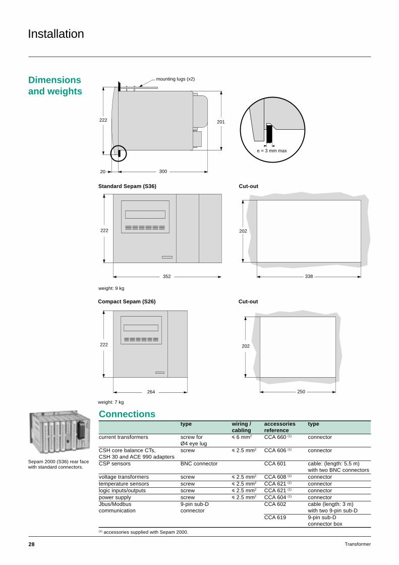
Installation
Dimensionsand weights
201
20 300
222
mounting lugs (x2)
Standard Sepam (S36) Cut-out
weight: 9 kg
352
222
Sepam 2000 (S36) rear facewith standard connectors.
Compact Sepam (S26) Cut-out
250
202222
264
weight: 7 kg
e = 3 mm max
338
202
Connectionstype wiring / accessories type
cabling referencecurrent transformers screw for i 6 mm2 CCA 660 (1) connector
Ø4 eye lugCSH core balance CTs, screw i 2.5 mm2 CCA 606 (1) connectorCSH 30 and ACE 990 adaptersCSP sensors BNC connector CCA 601 cable: (length: 5.5 m)
with two BNC connectorsvoltage transformers screw i 2.5 mm2 CCA 608 (1) connectortemperature sensors screw i 2.5 mm2 CCA 621 (1) connectorlogic inputs/outputs screw i 2.5 mm2 CCA 621 (1) connectorpower supply screw i 2.5 mm2 CCA 604 (1) connectorJbus/Modbus 9-pin sub-D CCA 602 cable (length: 3 m)communication connector with two 9-pin sub-D
CCA 619 9-pin sub-Dconnector box
(1) accessories supplied with Sepam 2000.

29Transformer
Notes

30 Transformer
Notes

31Transformer
PCRED398022EN /1ART.88628 12/ 1999
This document has beenprinted on ecological paper.
Schneider Electric SA Postal addressF-38050 Grenoble cedex 9Tel: 33 (0)4 76 57 60 60Telex: merge 320842 Fhttp://www.schneider-electric.com
As standards, specifications and designs change fromtime to time, please ask for confirmation of the informationgiven in this publication.
Publishing: Schneider Electric SADesign, production: IdraPrinting:Rcs Nanterre B 954 503 439
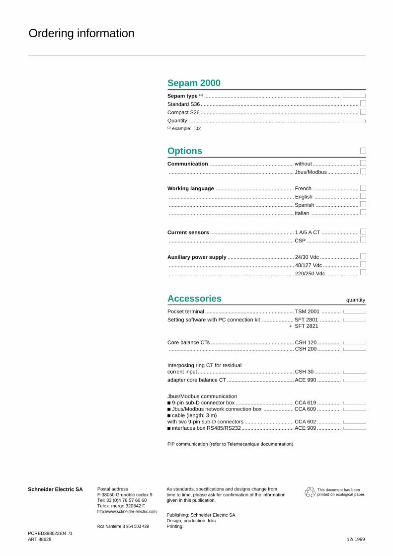
Sepam 2000Sepam type (1) .............................................................................................
Standard S36 ...........................................................................................................
Compact S26 ...........................................................................................................
Quantity .......................................................................................................(1) example: T02
OptionsCommunication ......................................................... without ...............................
..................................................................................... Jbus/Modbus .....................
Working language ..................................................... French ...............................
..................................................................................... English ..............................
..................................................................................... Spanish .............................
..................................................................................... Italian ................................
Current sensors ......................................................... 1 A/5 A CT .........................
..................................................................................... CSP ...................................
Auxiliary power supply ............................................. 24/30 Vdc ..........................
..................................................................................... 48/127 Vdc ........................
..................................................................................... 220/250 Vdc ......................
AccessoriesPocket terminal ............................................................ TSM 2001 .............
Setting software with PC connection kit ..................... SFT 2801 ..............+ SFT 2821
Core balance CTs ........................................................ CSH 120 ..................................................................................................... CSH 200 ................
Interposing ring CT for residualcurrent input ................................................................. CSH 30 ..................
adapter core balance CT ............................................. ACE 990 ................
Jbus/Modbus communicationc 9-pin sub-D connector box ....................................... CCA 619 ................c Jbus/Modbus network connection box .................... CCA 609 ................c cable (length: 3 m)with two 9-pin sub-D connectors ................................. CCA 602 ................c interfaces box RS485/RS232 ................................... ACE 909 ................
FIP communication (refer to Telemecanique documentation).
Ordering information
quantity