Embed Size (px)
Citation preview
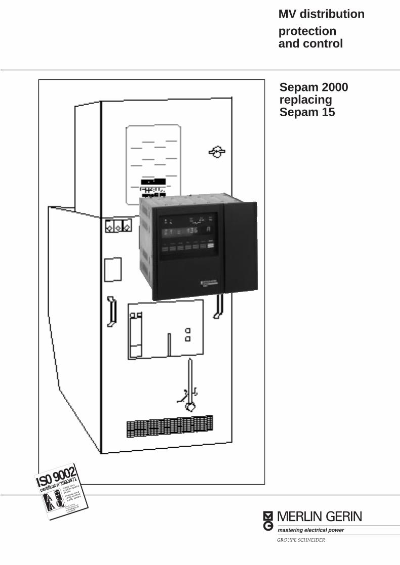
MV distributionprotectionand control
certificat n °1992/471
réalisé sous
système qualité
certifié
manufactured
under certified
quality system
IS0 9002
A FA Q
FAQ A A ASSOCIATION
FRANÇAISE POUR
L'ASSURANCE DE
LA QUALITE
Sepam 2000replacingSepam 15
GROUPE SCHNEIDER
MERLIN GERINmastering electrical power
1
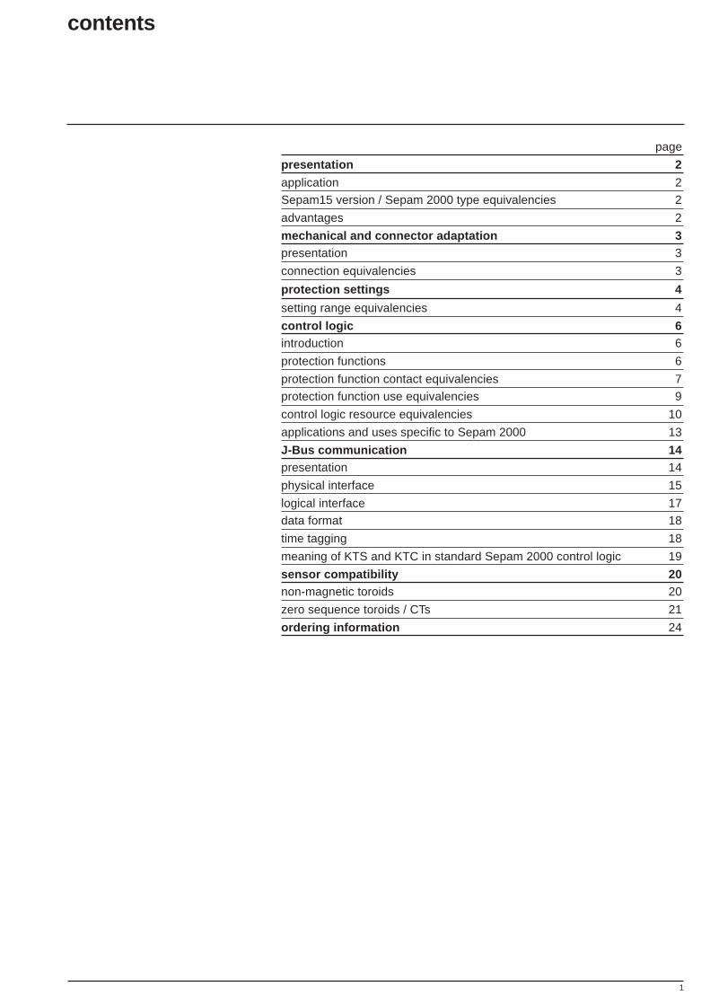
contents
page
presentation 2
application 2
Sepam15 version / Sepam 2000 type equivalencies 2
advantages 2
mechanical and connector adaptation 3presentation 3
connection equivalencies 3
protection settings 4
setting range equivalencies 4
control logic 6introduction 6
protection functions 6
protection function contact equivalencies 7
protection function use equivalencies 9
control logic resource equivalencies 10
applications and uses specific to Sepam 2000 13
J-Bus communication 14presentation 14
physical interface 15
logical interface 17
data format 18
time tagging 18
meaning of KTS and KTC in standard Sepam 2000 control logic 19
sensor compatibility 20non-magnetic toroids 20
zero sequence toroids / CTs 21
ordering information 24
2
presentation
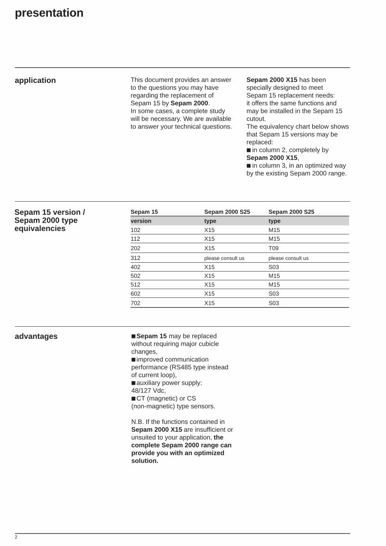
application This document provides an answerto the questions you may haveregarding the replacement ofSepam 15 by Sepam 2000 .In some cases, a complete studywill be necessary. We are availableto answer your technical questions.
Sepam 2000 X15 has beenspecially designed to meetSepam 15 replacement needs:it offers the same functions andmay be installed in the Sepam 15cutout.The equivalency chart below showsthat Sepam 15 versions may bereplaced: in column 2, completely bySepam 2000 X15 , in column 3, in an optimized wayby the existing Sepam 2000 range.
advantages Sepam 15 may be replacedwithout requiring major cubiclechanges, improved communicationperformance (RS485 type insteadof current loop), auxiliary power supply:48/127 Vdc, CT (magnetic) or CS(non-magnetic) type sensors.
N.B. If the functions contained inSepam 2000 X15 are insufficient orunsuited to your application, thecomplete Sepam 2000 range canprovide you with an optimizedsolution.
Sepam 15 version /Sepam 2000 typeequivalencies
Sepam 15 Sepam 2000 S25 Sepam 2000 S25
version type type
102 X15 M15
112 X15 M15
202 X15 T09
312 please consult us please consult us
402 X15 S03
502 X15 M15
512 X15 M15
602 X15 S03
702 X15 S03
3
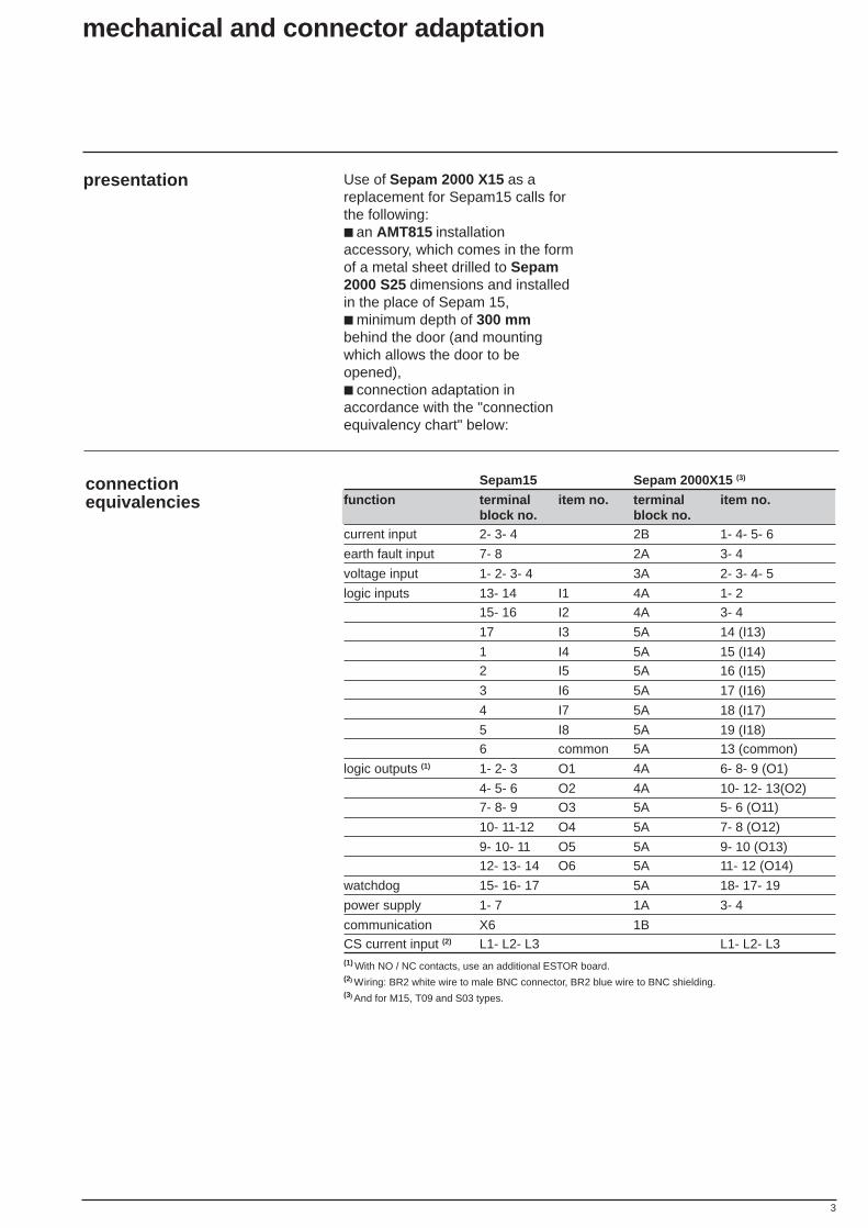
presentation Use of Sepam 2000 X15 as areplacement for Sepam15 calls forthe following: an AMT815 installationaccessory, which comes in the formof a metal sheet drilled to Sepam2000 S25 dimensions and installedin the place of Sepam 15, minimum depth of 300 mmbehind the door (and mountingwhich allows the door to beopened), connection adaptation inaccordance with the "connectionequivalency chart" below:
mechanical and connector adaptation
connectionequivalencies
(1) With NO / NC contacts, use an additional ESTOR board.(2) Wiring: BR2 white wire to male BNC connector, BR2 blue wire to BNC shielding.(3) And for M15, T09 and S03 types.
Sepam15 Sepam 2000X15 (3)
function terminal item no. terminal item no.block no. block no.
current input 2- 3- 4 2B 1- 4- 5- 6
earth fault input 7- 8 2A 3- 4
voltage input 1- 2- 3- 4 3A 2- 3- 4- 5
logic inputs 13- 14 I1 4A 1- 215- 16 I2 4A 3- 4
17 I3 5A 14 (I13)
1 I4 5A 15 (I14)2 I5 5A 16 (I15)
3 I6 5A 17 (I16)
4 I7 5A 18 (I17)
5 I8 5A 19 (I18)6 common 5A 13 (common)
logic outputs (1) 1- 2- 3 O1 4A 6- 8- 9 (O1)
4- 5- 6 O2 4A 10- 12- 13(O2)7- 8- 9 O3 5A 5- 6 (O11)
10- 11-12 O4 5A 7- 8 (O12)
9- 10- 11 O5 5A 9- 10 (O13)12- 13- 14 O6 5A 11- 12 (O14)
watchdog 15- 16- 17 5A 18- 17- 19
power supply 1- 7 1A 3- 4
communication X6 1BCS current input (2) L1- L2- L3 L1- L2- L3
4
protection settings
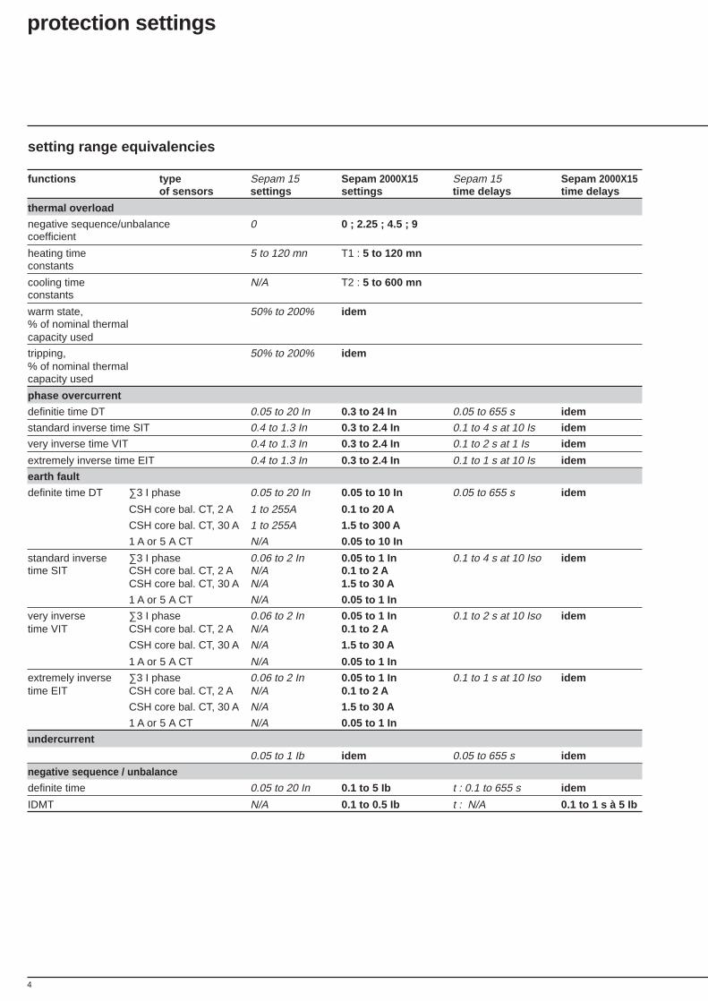
setting range equivalencies
functions type Sepam 15 Sepam 2000X15 Sepam 15 Sepam 2000X15of sensors settings settings time delays time delays
thermal overload
negative sequence/unbalance 0 0 ; 2.25 ; 4.5 ; 9coefficient
heating time 5 to 120 mn T1 : 5 to 120 mnconstants
cooling time N/A T2 : 5 to 600 mnconstants
warm state, 50% to 200% idem% of nominal thermalcapacity used
tripping, 50% to 200% idem% of nominal thermalcapacity used
phase overcurrent
definitie time DT 0.05 to 20 In 0.3 to 24 In 0.05 to 655 s idem
standard inverse time SIT 0.4 to 1.3 In 0.3 to 2.4 In 0.1 to 4 s at 10 Is idem
very inverse time VIT 0.4 to 1.3 In 0.3 to 2.4 In 0.1 to 2 s at 1 Is idem
extremely inverse time EIT 0.4 to 1.3 In 0.3 to 2.4 In 0.1 to 1 s at 10 Is idem
earth fault
definite time DT ∑3 I phase 0.05 to 20 In 0.05 to 10 In 0.05 to 655 s idem
CSH core bal. CT, 2 A 1 to 255A 0.1 to 20 A
CSH core bal. CT, 30 A 1 to 255A 1.5 to 300 A
1 A or 5 A CT N/A 0.05 to 10 In
standard inverse ∑3 I phase 0.06 to 2 In 0.05 to 1 In 0.1 to 4 s at 10 Iso idemtime SIT CSH core bal. CT, 2 A N/A 0.1 to 2 A
CSH core bal. CT, 30 A N/A 1.5 to 30 A
1 A or 5 A CT N/A 0.05 to 1 In
very inverse ∑3 I phase 0.06 to 2 In 0.05 to 1 In 0.1 to 2 s at 10 Iso idemtime VIT CSH core bal. CT, 2 A N/A 0.1 to 2 A
CSH core bal. CT, 30 A N/A 1.5 to 30 A
1 A or 5 A CT N/A 0.05 to 1 In
extremely inverse ∑3 I phase 0.06 to 2 In 0.05 to 1 In 0.1 to 1 s at 10 Iso idemtime EIT CSH core bal. CT, 2 A N/A 0.1 to 2 A
CSH core bal. CT, 30 A N/A 1.5 to 30 A
1 A or 5 A CT N/A 0.05 to 1 In
undercurrent
0.05 to 1 Ib idem 0.05 to 655 s idem
negative sequence / unbalance
definite time 0.05 to 20 In 0.1 to 5 Ib t : 0.1 to 655 s idem
IDMT N/A 0.1 to 0.5 Ib t : N/A 0.1 to 1 s à 5 Ib

5
setting range equivalencies (cont'd)
functions type Sepam 15 Sepam 2000X15 Sepam 15 Sepam2000X15of sensors settings settings time delays time delays
locked rotor/excessive starting time
2.5 Is fixed 0.5 to 5 Ib
starting time ST 0.5 to 655 s idem
time delay LT 0.05 to 655 s idem
starts per hour
starts per hour 1 to 200 1 to 60consecutive cold starts N/A 1 to 60consecutive hot starts N/A 1 to 60time between starts 0.5 to 655 s idem
undervoltage
0.05 to 1.2 Un 0.05 to 1Un 0.05 to 655 s idem
overvoltage
0,5 to 2 Un 0.5 to 1.5 Un 0.05 to 655 s idem
directional overcurrent
characteristic angle 0°, 30°, 45°, 30°, 45°, 60°60°,90°
definite time DT 0.05 0.3 to 24 In 0.05 to 655 s idemto 20 In
standard inverse time SIT 0.4 0.3 to 2.4 In 0.1 to 4 s at 10 Is idemto 1.3 In
very inverse time 0.4 0.3 to 2.4 In 0.1 to 2 s at 10 Is idemVIT to 1.3 In
extremely inverse 0.4 0.3 to 2.4 In 0.1 to 1 s at 10 Is idemtime EIT to 1.3 In
directional earth fault
characteristic angle 0°, 30°, 45°, 0°, 15°, 30°,60°, 90° 45°,60°,90°
and -45°definite time DT ∑3 I phase 0.05 to 20 In 0.05 to 10 In 0.05 to 655 s idem
CSH core bal. CT, 2 A 1 to 255 A 0.1 to 20 A
CSH core bal. CT, 30 A 1 to 255 A 1.5 to 300 A
1 A or 5 A CT N/A 0.05 to 10 In
Reminder: rated current In, rated voltage Un and current Ino are general parameters that are set at the time of Sepam commissioning.In is the current sensor rated current (CT rating). Un is the rated phase-to-phase voltage of the voltage sensor primary windings.Ib: equipment basis current set adjustable from 0.4 to 1.3 In.
6
control logic
introduction Sepam 15 control logic may beconverted to Sepam 2000 controllogic by implementing the technicalrecommendations given in thechapters which follow.These chapters highlight theparticularities related to conversionand emphasize the following points: existence and availability ofresources, resource equivalencies, comments on customary andspecial uses.
protection functions To replace Sepam 15 bySepam 2000, it is necessary toread 4 charts: Sepam 15 version / Sepam 2000equivalency chart (refer to p. 2), protection function contactequivalency chart (refer to p. 7), protection function useequivalency chart (refer to p. 9), resource equivalency chart(refer to p. 10).
7
control logic (cont'd)
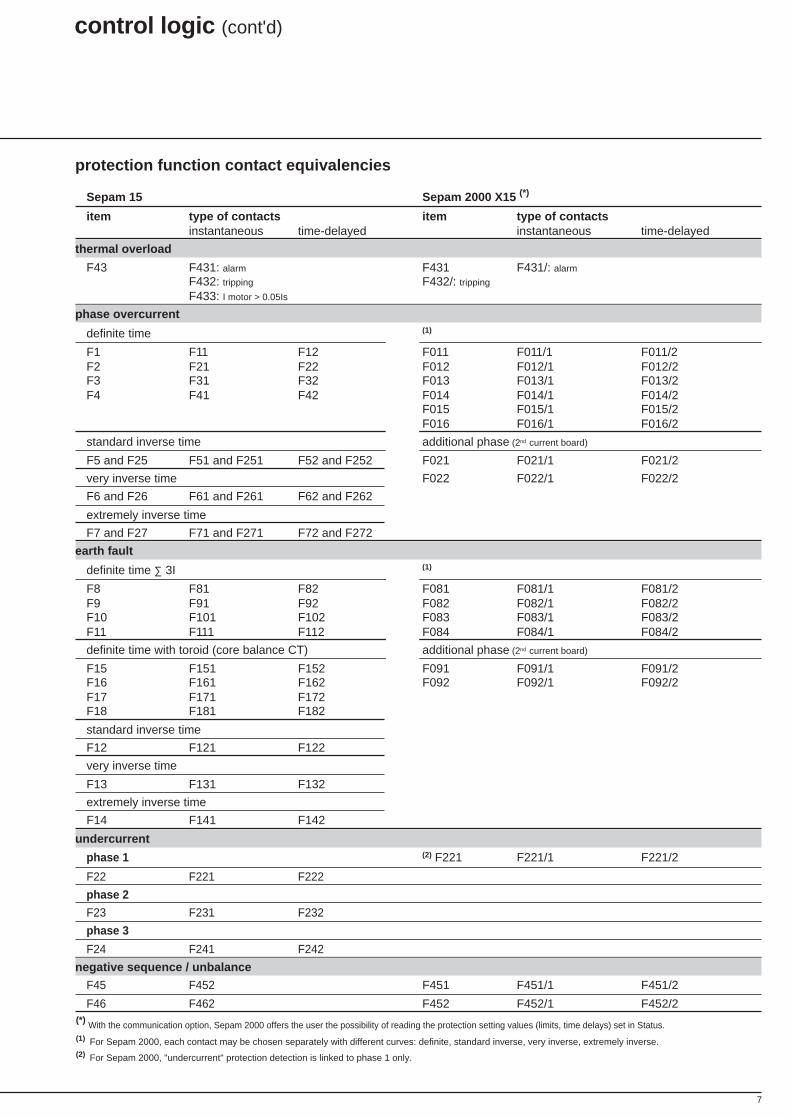
(*) With the communication option, Sepam 2000 offers the user the possibility of reading the protection setting values (limits, time delays) set in Status.(1) For Sepam 2000, each contact may be chosen separately with different curves: definite, standard inverse, very inverse, extremely inverse.(2) For Sepam 2000, "undercurrent" protection detection is linked to phase 1 only.
protection function contact equivalencies
Sepam 15 Sepam 2000 X15 (*)
item type of contacts item type of contactsinstantaneous time-delayed instantaneous time-delayed
thermal overload
F43 F431: alarm F431 F431/: alarm
F432: tripping F432/: tripping
F433: I motor > 0.05Is
phase overcurrent
definite time (1)
F1 F11 F12 F011 F011/1 F011/2F2 F21 F22 F012 F012/1 F012/2F3 F31 F32 F013 F013/1 F013/2F4 F41 F42 F014 F014/1 F014/2
F015 F015/1 F015/2F016 F016/1 F016/2
standard inverse time additional phase (2nd current board)
F5 and F25 F51 and F251 F52 and F252 F021 F021/1 F021/2
very inverse time F022 F022/1 F022/2
F6 and F26 F61 and F261 F62 and F262
extremely inverse time
F7 and F27 F71 and F271 F72 and F272
earth fault
definite time ∑ 3I (1)
F8 F81 F82 F081 F081/1 F081/2F9 F91 F92 F082 F082/1 F082/2F10 F101 F102 F083 F083/1 F083/2F11 F111 F112 F084 F084/1 F084/2
definite time with toroid (core balance CT) additional phase (2nd current board)
F15 F151 F152 F091 F091/1 F091/2F16 F161 F162 F092 F092/1 F092/2F17 F171 F172F18 F181 F182
standard inverse time
F12 F121 F122
very inverse time
F13 F131 F132
extremely inverse time
F14 F141 F142
undercurrent
phase 1 (2) F221 F221/1 F221/2
F22 F221 F222
phase 2
F23 F231 F232
phase 3
F24 F241 F242
negative sequence / unbalance
F45 F452 F451 F451/1 F451/2
F46 F462 F452 F452/1 F452/2
8
control logic (cont'd)
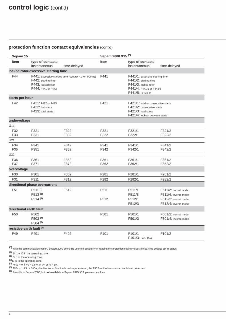
protection function contact equivalencies (cont'd)
Sepam 15 Sepam 2000 X15 (*)
item type of contacts item type of contactsinstantaneous time-delayed instantaneous time-delayed
locked rotor/excessive starting time
F44 F441: excessive starting time (contact =1 for 500ms) F441 F441/1: excessive starting time
F442: starting time F441/2: starting time
F443: locked rotor F441/3: locked rotor
F444: F441 or F443 F441/4: F441/1 or F443/3
F441/5: I > 5% Ib
starts per hour
F42 F421: F422 or F423 F421 F421/1: total or consecutive starts
F422: hot starts F421/2: consecutive starts
F423: total starts F421/3: total starts
F421/4: lockout between starts
undervoltage
U13
F32 F321 F322 F321 F321/1 F321/2F33 F331 F332 F322 F322/1 F322/2
U21
F34 F341 F342 F341 F341/1 F341/2F35 F351 F352 F342 F342/1 F342/2
U32
F36 F361 F362 F361 F361/1 F361/2F37 F371 F372 F362 F362/1 F362/2
overvoltage
F30 F301 F302 F281 F281/1 F281/2
F31 F311 F312 F282 F282/1 F282/2
directional phase overcurrent
F51 F511 (1) F512 F511 F511/1 F511/2: normal mode
F513 (2) F511/3 F511/4: inverse mode
F514 (3) F512 F512/1 F512/2: normal mode
F512/3 F512/4: inverse mode
directional earth fault
F50 F502 F501 F501/1 F501/2: normal mode
F503 (4) F501/3 F501/4: inverse mode
F504 (5)
resistive earth fault (6)
F49 F491 F492 F101 F101/1 F101/2F101/3: Io > 15 A
(*) With the communication option, Sepam 2000 offers the user the possibility of reading the protection setting values (limits, time delays) set in Status.(1) Si I1 or I3 in the operating zone.(2) Si I1 in the operating zone.(3) Si I3 in the operating zone.(4) F503 = 0, if Vo > 1.5 % of Un or Io < 1A.(5) F504 = 1, if Io < 300A, the directional function is no longer ensured; the F50 function becomes an earth fault protection.(6) Possible in Sepam 2000, but not available in Sepam 2025 X15; please consult us.
9
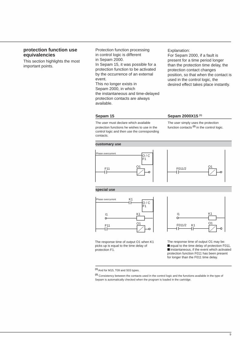
protection function useequivalenciesThis section highlights the mostimportant points.
Explanation:For Sepam 2000, if a fault ispresent for a time period longerthan the protection time delay, theprotection contact changesposition, so that when the contact isused in the control logic, thedesired effect takes place instantly.
Protection function processingin control logic is differentin Sepam 2000.In Sepam 15, it was possible for aprotection function to be activatedby the occurrence of an externalevent.This no longer exists inSepam 2000, in whichthe instantaneous and time-delayedprotection contacts are alwaysavailable.
Sepam 15 Sepam 2000X15 (1)
The user must declare which available The user simply uses the protectionprotection functions he wishes to use in the function contacts (2) in the control logic.control logic and then use the correspondingcontacts.
customary use
special use
F11O1
O / CF1
Phase overcurrent
F011/2O1
F011/2O1
K1I1
K1F11O1
O / CF1
Phase overcurrent K1
K1I1
The response time of output O1 when K1picks up is equal to the time delay ofprotection F1.
The response time of output O1 may be: equal to the time delay of protection F011, instantaneous, if the event which activatedprotection function F011 has been presentfor longer than the F011 time delay.
(1) And for M15, T09 and S03 types.(2) Consistency between the contacts used in the control logic and the functions available in the type ofSepam is automatically checked when the program is loaded in the cartridge.
10
control logic resource equivalencies
control logic (cont'd)
Sepam 15 Sepam 2000X15 (1) Comments, changes, differentiation
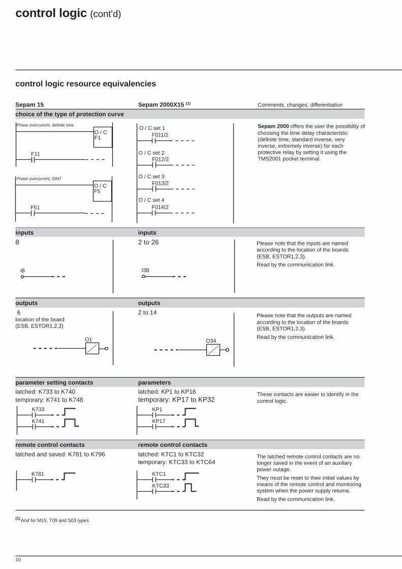
choice of the type of protection curve
inputs inputs
8 2 to 26
outputs outputs
6 2 to 14location of the board(ESB, ESTOR1,2,3)
parameter setting contacts parameters
latched: K733 to K740 latched: KP1 to KP16temporary: K741 to K748 temporary: KP17 to KP32
remote control contacts remote control contacts
latched and saved: K781 to K796 latched: KTC1 to KTC32temporary: KTC33 to KTC64
F11
O / CF1
Phase overcurrent, definite time
F51
O / CF5
Phase overcurrent, IDMT
Sepam 2000 offers the user the possibility ofchoosing the time delay characteristic(definite time, standard inverse, veryinverse, extremely inverse) for eachprotective relay by setting it using theTMS2001 pocket terminal.
F011/2
F012/2
O / C set 1
O / C set 2
O / C set 3F013/2
O / C set 4F014/2
Please note that the outputs are namedaccording to the location of the boards(ESB, ESTOR1,2,3).
Read by the communication link.
Please note that the inputs are namedaccording to the location of the boards(ESB, ESTOR1,2,3).
Read by the communication link.
These contacts are easier to identify in thecontrol logic.
The latched remote control contacts are nolonger saved in the event of an auxiliarypower outage.
They must be reset to their initial values bymeans of the remote control and monitoringsystem when the power supply returns.
Read by the communication link.
I38I8
O34O1
K781
K733
K741
KP1
KP17
KTC1
KTC33
(1) And for M15, T09 and S03 types.
11
Sepam 15 Sepam 2000X15 (1) Comments, changes, differentiation
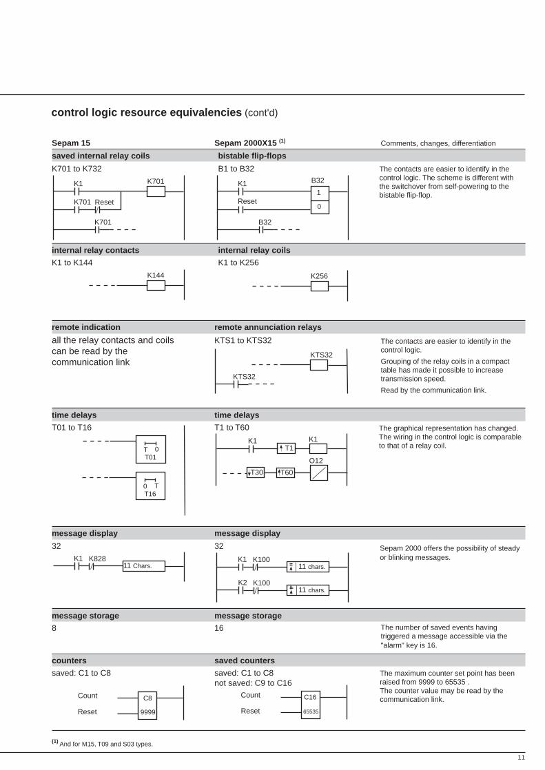
saved internal relay coils bistable flip-flops
K701 to K732 B1 to B32
internal relay contacts internal relay coils
K1 to K144 K1 to K256
remote indication remote annunciation relays
all the relay contacts and coils KTS1 to KTS32can be read by thecommunication link
time delays time delays
T01 to T16 T1 to T60
message display message display
32 32
message storage message storage
8 16
counters saved counters
saved: C1 to C8 saved: C1 to C8not saved: C9 to C16
control logic resource equivalencies (cont'd)
K1
K701
K701
Reset
K701 K1
B32
Reset
B32
1
0
K256
The contacts are easier to identify in thecontrol logic. The scheme is different withthe switchover from self-powering to thebistable flip-flop.
C16
65535
Count
Reset
K144
C8
9999Reset
Count
The contacts are easier to identify in thecontrol logic.
Grouping of the relay coils in a compacttable has made it possible to increasetransmission speed.
Read by the communication link.
The number of saved events havingtriggered a message accessible via the"alarm" key is 16.
0TT01
T0T16
O12
K1K1T1
T60T30
K111 chars.
K100
K2 K10011 chars.
K111 Chars.
K828
KTS32
KTS32
The maximum counter set point has beenraised from 9999 to 65535 .The counter value may be read by thecommunication link.
Sepam 2000 offers the possibility of steadyor blinking messages.
The graphical representation has changed.The wiring in the control logic is comparableto that of a relay coil.
(1) And for M15, T09 and S03 types.
12
control logic resource equivalencies (cont'd)
Sepam 15 Sepam 2000X15 (1)
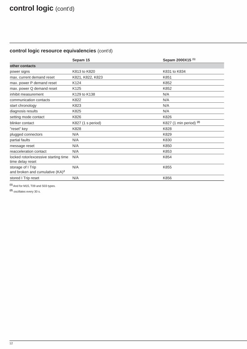
other contacts
power signs K813 to K820 K831 to K834
max. current demand reset K821, K822, K823 K851
max. power P demand reset K124 K852
max. power Q demand reset K125 K852
inhibit measurement K129 to K138 N/A
communication contacts K822 N/A
start chronology K823 N/A
diagnosis results K825 N/A
setting mode contact K826 K826
blinker contact K827 (1 s period) K827 (1 min period) (2)
"reset" key K828 K828
plugged connectors N/A K829
partial faults N/A K830
message reset N/A K850
reacceleration contact N/A K853
locked rotor/excessive starting time N/A K854time delay reset
storage of I Trip N/A K855and broken and cumulative (KA)2
stored I Trip reset N/A K856
control logic (cont'd)
(1) And for M15, T09 and S03 types.(2) oscillates every 30 s.
13
F12
K701
K701
K828
K701
K828O / C
applications and usesspecific to Sepam 2000
Sepam 15 Sepam 2000X15 (1) Comments, changes, differentiation
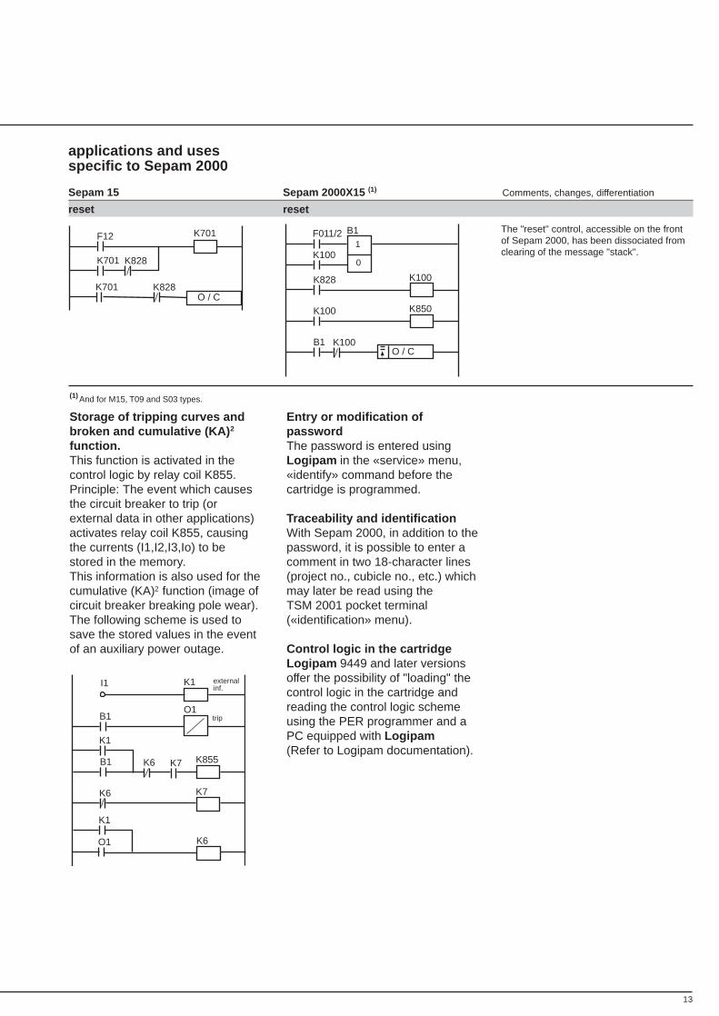
reset reset
The "reset" control, accessible on the frontof Sepam 2000, has been dissociated fromclearing of the message "stack".
1
0
F011/2
K100
K828 K100
K100 K850
B1O / C
K100
B1
Storage of tripping curves andbroken and cumulative (KA) 2
function.This function is activated in thecontrol logic by relay coil K855.Principle: The event which causesthe circuit breaker to trip (orexternal data in other applications)activates relay coil K855, causingthe currents (I1,I2,I3,Io) to bestored in the memory.This information is also used for thecumulative (KA)2 function (image ofcircuit breaker breaking pole wear).The following scheme is used tosave the stored values in the eventof an auxiliary power outage.
Entry or modification ofpasswordThe password is entered usingLogipam in the «service» menu,«identify» command before thecartridge is programmed.
Traceability and identificationWith Sepam 2000, in addition to thepassword, it is possible to enter acomment in two 18-character lines(project no., cubicle no., etc.) whichmay later be read using theTSM 2001 pocket terminal(«identification» menu).
Control logic in the cartridgeLogipam 9449 and later versionsoffer the possibility of "loading" thecontrol logic in the cartridge andreading the control logic schemeusing the PER programmer and aPC equipped with Logipam(Refer to Logipam documentation).
B1 K855
K1
K6
B1
K1I1
K7K6
K7
O1
K1
O1 K6
externalinf.
trip
(1) And for M15, T09 and S03 types.
14
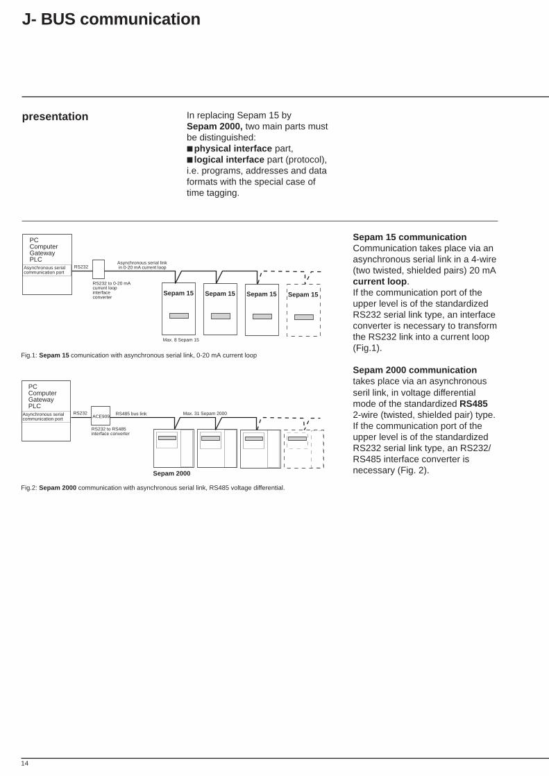
In replacing Sepam 15 bySepam 2000, two main parts mustbe distinguished: physical interface part, logical interface part (protocol),i.e. programs, addresses and dataformats with the special case oftime tagging.
presentation
Sepam 15 communicationCommunication takes place via anasynchronous serial link in a 4-wire(two twisted, shielded pairs) 20 mAcurrent loop .If the communication port of theupper level is of the standardizedRS232 serial link type, an interfaceconverter is necessary to transformthe RS232 link into a current loop(Fig.1).
Sepam 2000 communicationtakes place via an asynchronousseril link, in voltage differentialmode of the standardized RS4852-wire (twisted, shielded pair) type.If the communication port of theupper level is of the standardizedRS232 serial link type, an RS232/RS485 interface converter isnecessary (Fig. 2).
J- BUS communication
PCComputerGatewayPLC
Asynchronous serialcommunication port
Sepam 15 Sepam 15 Sepam 15 Sepam 15
RS232 to 0-20 mAcurrent loop interfaceconverter
Asynchronous serial link in 0-20 mA current loop
Max. 8 Sepam 15
RS232
Sepam 2000
RS485 bus link Max. 31 Sepam 2000RS232 ACE909
PCComputerGatewayPLC
Asynchronous serialcommunication port
RS232 to RS485interface converter
Fig.1: Sepam 15 comunication with asynchronous serial link, 0-20 mA current loop
Fig.2: Sepam 2000 communication with asynchronous serial link, RS485 voltage differential.
15
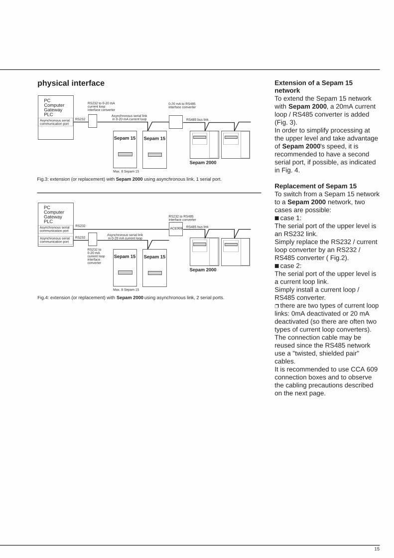
Extension of a Sepam 15networkTo extend the Sepam 15 networkwith Sepam 2000, a 20mA currentloop / RS485 converter is added(Fig. 3).In order to simplify processing atthe upper level and take advantageof Sepam 2000 's speed, it isrecommended to have a secondserial port, if possible, as indicatedin Fig. 4.
Replacement of Sepam 15To switch from a Sepam 15 networkto a Sepam 2000 network, twocases are possible: case 1:The serial port of the upper level isan RS232 link.Simply replace the RS232 / currentloop converter by an RS232 /RS485 converter ( Fig.2). case 2:The serial port of the upper level isa current loop link.Simply install a current loop /RS485 converter. there are two types of current looplinks: 0mA deactivated or 20 mAdeactivated (so there are often twotypes of current loop converters).The connection cable may bereused since the RS485 networkuse a "twisted, shielded pair"cables.It is recommended to use CCA 609connection boxes and to observethe cabling precautions describedon the next page.
physical interface
Fig.3: extension (or replacement) with Sepam 2000 using asynchronous link, 1 serial port.
Sepam 15 Sepam 15
Max. 8 Sepam 15
RS232
Sepam 2000
RS485 bus link
PCComputerGatewayPLC
Asynchronous serialcommunication port
RS232 to 0-20 mAcurrent loop interface converter
Asynchronous serial link in 0-20 mA current loop
0-20 mA to RS485interface converter
Sepam 15 Sepam 15
Max. 8 Sepam 15
RS232
Sepam 2000
RS485 bus linkACE909RS232
PCComputerGatewayPLC
Asynchronous serialcommunication port
RS232 to 0-20 mAcurrent loop interfaceconverter
Asynchronous serial link in 0-20 mA current loopAsynchronous serial
communication port
RS232 to RS485 interface converter
Fig.4: extension (or replacement) with Sepam 2000 using asynchronous link, 2 serial ports.

16
J- BUS communication (cont'd)
Cabling precautionsThese precautions are aimed atensuring cable shielding continuityand correct grounding.The CCA602 branching cablesprovide shielding continuitybetween Sepam 2000 and theconnection boxes; Make sure that the twoconnectors at the ends of the cableare plugged in correctly and lockedby the two screws speciallyprovided.Shielding should be continuousthroughout the RS485 network.Each box includes two cableclamps.They ensure cable shieldingcontinuity and grounding via theterminal specially provided. Make sure that the clamps aretightened onto the metallicshielding braid and not onto theinsulation. Make sure that each connectionbox is grounded by the 2.5 mm2
"green-yellow" wire or a shortconnection braid (less than 10 cmlong).For electrical distribution systems inwhich the earthing systems arenot equipotential or separated, thestipulations made by the standardsin effect should be applied.A "low voltage" type cable trayshould be used for the RS485communication network cable.For further information andrecommendations, please refer tothe Telemecanique TSX DG GND Fdocument entitled, "groundingcabling guide".
physical interface (cont'd) Setting link parametersTo set the parameters of theSepam 15 link, it is necessary to: Impose: transmission format:1 start bit start / 8 working bits/1 even parity bit / 1 stop bit, Set the parameters for: type of current loop:0 or 20 mA when line isdeactivated. slave number:1 to 255 transmission speed:300 to 4800 BaudsTo set the parameters of theSepam 2000 link, it is necessary to: Impose: transmission format:1 start bit / 8 working bits/1 parity bit / 1 stop bit, Set the parameters for: parity:even, odd or no parity, slave number:1 to 255, transmission speed:300 to 38400 Bauds.Sepam 2000s may be added to thenetwork by setting their parametersin the same way as for theSepam15s already included in thenetwork.
17
Sepam tables and adressingstarting end functions meaning Sepam 2000address address enabled or error equivalency
0000 0001 1,2,3,4 diagnosis 0C8Ftable Sepam check
0002 000A 1,2,3,4 internal relay contacts (1) see KTSK1 to K129 or KTC
000B 1,2,3,4 time delay (3) D080 request tableT1 to T16 D000 reply table
000C 1,2,3,4 counters 0C40 eventC1 to C8 counters
000D 1,2,3,4 inputs I1 to I8 0C10input bits
000E 1,2,3,4 outputs O1 to O6 0C20output bits
000F 0011 1,2,3,4 internal relay contacts (1) see KTSK701 à K748 or KTC
0012 1,2,3,4,5,6 internal relay contacts (1) see KTCK781 à K796
0013 001A internal relay contacts (1) see KTSK813 à K940 or KTC
001B 01FF not used
0200 0231 1,2,3,4 protections (*)noF11 to F998 equivalency
0232 02FF not used
0300.. ..... 3,4 protection (3) D080 request table......... ...04FF setting D000 reply table
reading
0500 051C 3,4 Measurement FA00, measurements x 1reading FB00, measurements x 10U, I, P, Q,energy, Cos, F.
051D 05FF not used
0600 3,4,6 time tagging (2) see section oncommand n° Sepam 2000 time tagging
0601 0623 3,4,6 time tagging (2) see section onevents Sepam 2000 time tagging
0624 062B 1,2,3,4, time tagging (2) see section onE, V registers Sepam 2000 time tagging
062C 06FF not used (2) see section onSepam 2000 time tagging
0700 070F 3,4 reading of (3) D080 request tabletime delay D000 reply tableT1 to T16set points
0710 0717 3,4 counter status 0C40C1 to C8 remote measurement
counters
0718 07FF not used
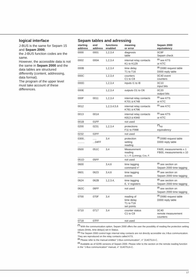
logical interfaceJ-BUS is the same for Sepam 15and Sepam 2000 ;the J-BUS function codes are thesame.However, the accessible data is notthe same in Sepam 2000 and thedata tables are structureddifferently (content, addressing,data format).The program of the upper levelmust take account of thesedifferences.
(*) With the communication option, Sepam 2000 offers the user the possiblity of reading the protection settingvalues (limits, time delays) set in Status.(1) The Sepam 2000 control logic internal relay contacts are not directly accessible via J-Bus communication.They are reproduced on the relay contacts called KTS.(2) Please refer to the manual entitled "J-Bus communication", n° 3140751A-C.(3) Available as of 02/95 versions of Sepam 2000. Please refer to the section on the remote reading functionin the "J-Bus communication" manual, n° 3140751A-C.
18
J- BUS communication (cont'd)
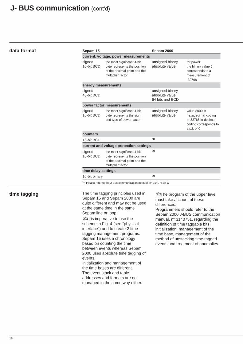
data format Sepam 15 Sepam 2000
current, voltage, power measurements
signed the most significant 4-bit unsigned binary for power:16-bit BCD byte represents the position absolute value the binary value 0
of the decimal point and the corresponds to amultiplier factor measurement of
-32768
energy measurements
signed unsigned binary48-bit BCD absolute value
64 bits and BCD
power factor measurements
signed the most significant 4-bit unsigned binary value 8000 in16-bit BCD byte represents the sign absolute value hexadecimal coding
and type of power factor or 32768 in decimalcoding corresponds toa p.f. of 0
counters
16-bit BCD (1)
current and voltage protection settings
signed the most significant 4-bit (1)
16-bit BCD byte represents the positionof the decimal point and themultiplier factor
time delay settings
16-bit binary (1)
(1) Please refer to the J-Bus communication manual, n° 3140751A-C
time tagging The time tagging principles used inSepam 15 and Sepam 2000 arequite different and may not be usedat the same time in the sameSepam line or loop. It is imperative to use thescheme in Fig. 4 (see "physicalinterface") and to create 2 timetagging management programs.Sepam 15 uses a chronologybased on counting the timebetween events whereas Sepam2000 uses absolute time tagging ofevents.Initialization and management ofthe time bases are different.The event stack and tableaddresses and formats are notmanaged in the same way either.
The program of the upper levelmust take account of thesedifferences.Programmers should refer to theSepam 2000 J-BUS communicationmanual, n° 3140751, regarding thedefinition of time taggable bits,initialization, management of thetime base, management of themethod of unstacking time-taggedevents and treatment of anomalies.
19
meaning of KTSand KTC in standardSepam 2000 control logic
Only the KTS and KTC contactsdefined in the standard control logicare accessible via communication.For their meanings, please refer tothe Sepam 2000 technical manualfor each specific application.The meaning of contacts may bedifferent when the control logic hasbeen customized.
20
sensor compatibility
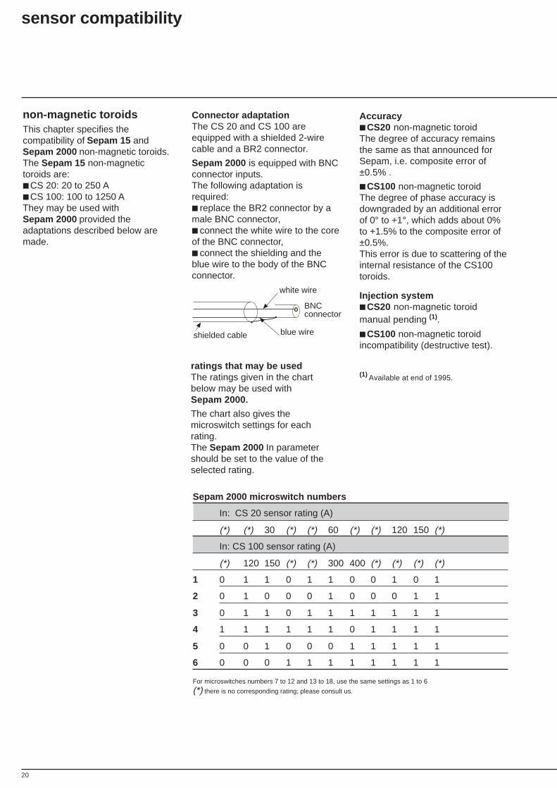
non-magnetic toroidsThis chapter specifies thecompatibility of Sepam 15 andSepam 2000 non-magnetic toroids.The Sepam 15 non-magnetictoroids are: CS 20: 20 to 250 A CS 100: 100 to 1250 AThey may be used withSepam 2000 provided theadaptations described below aremade.
Connector adaptationThe CS 20 and CS 100 areequipped with a shielded 2-wirecable and a BR2 connector.
Sepam 2000 is equipped with BNCconnector inputs.The following adaptation isrequired: replace the BR2 connector by amale BNC connector, connect the white wire to the coreof the BNC connector, connect the shielding and theblue wire to the body of the BNCconnector.
white wire
blue wireshielded cable
BNC connector
ratings that may be usedThe ratings given in the chartbelow may be used withSepam 2000.
The chart also gives themicroswitch settings for eachrating.The Sepam 2000 In parametershould be set to the value of theselected rating.
Sepam 2000 microswitch numbers
In: CS 20 sensor rating (A)
(*) (*) 30 (*) (*) 60 (*) (*) 120 150 (*)
In: CS 100 sensor rating (A)
(*) 120 150 (*) (*) 300 400 (*) (*) (*) (*)
1 0 1 1 0 1 1 0 0 1 0 1
2 0 1 0 0 0 1 0 0 0 1 1
3 0 1 1 0 1 1 1 1 1 1 1
4 1 1 1 1 1 1 0 1 1 1 1
5 0 0 1 0 0 0 1 1 1 1 1
6 0 0 0 1 1 1 1 1 1 1 1
For microswitches numbers 7 to 12 and 13 to 18, use the same settings as 1 to 6
(*) there is no corresponding rating; please consult us.
Accuracy CS20 non-magnetic toroidThe degree of accuracy remainsthe same as that announced forSepam, i.e. composite error of±0.5% .
CS100 non-magnetic toroidThe degree of phase accuracy isdowngraded by an additional errorof 0° to +1°, which adds about 0%to +1.5% to the composite error of±0.5%.This error is due to scattering of theinternal resistance of the CS100toroids.
Injection system CS20 non-magnetic toroidmanual pending (1).
CS100 non-magnetic toroidincompatibility (destructive test).
(1) Available at end of 1995.
21
zero sequence toroids /CTs
This chapter specifies thecompatibility between Sepam15zero sequence toroids andSepam 2000 core balance andinterposing ring CTs. Sepam 15 toroids MN (diameter 120, white), SN (diameter 200, white), TF (diameter 30, green), PF (diameter 50, green), MF (diameter 100, green), SF (diameter 200, green), GF (diameter 300, green), PO (diameter 46, split), GO (diameter 110, split). Sepam 2000 CTs CSH 30 (diameter 30), CSH 120 (diameter 120), CSH 200 (diameter 200).
AccuracyThe Sepam 15 toroids have thesame winding ratio as the CSH CTsdesigned for Sepam 2000. Theyare therefore compatible withSepam 2000.The ± 5% degree of measurementaccuracy is the same.The phase accuracy of the previousgeneration of toroids is not known. Do not use Sepam 15 toroids fordirectional earth protections...
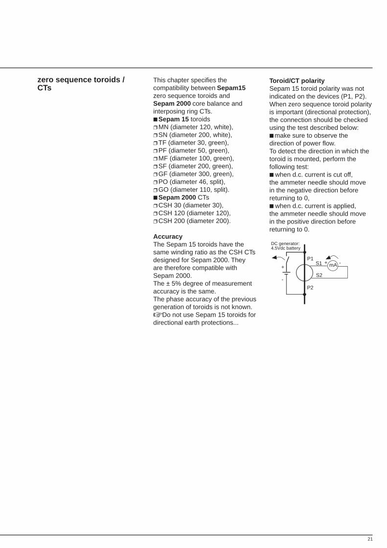
Toroid/CT polaritySepam 15 toroid polarity was notindicated on the devices (P1, P2).When zero sequence toroid polarityis important (directional protection),the connection should be checkedusing the test described below: make sure to observe thedirection of power flow.To detect the direction in which thetoroid is mounted, perform thefollowing test: when d.c. current is cut off,the ammeter needle should movein the negative direction beforereturning to 0, when d.c. current is applied,the ammeter needle should movein the positive direction beforereturning to 0.
+
-
mAP1
P2
S2
S1 + -
DC generator:4.5Vdc battery

22
sensor compatibility (cont'd)
zero sequence toroids /CTs (cont'd)
0,1 Ω 1 Ω
20 A
80 A
RF
Imm
2 Ω 10 Ω
100 A
300 A
30 Atoroïdrating
CSH 200SF-GFSN-POGO
CSH 120MF-PF
CSH 30TF
CSH 30CSH 120CSH 200+ All other toroïds
50 A
MN
5 Ω
2 Atoroïdrating
Notes :There are no saturation problemsfor the 2A rating, whatever thetoroid, up to a wiring resistanceof 10Ω.With the 30A rating, up to a wiringresistance of 1Ω, there are nosaturation problems for any of thetoroids except for CSH30 and TF.The MN toroid (diameter 120 white)saturates above a wiring resistanceof 1Ω for the 30A rating.The CSH120, MF and PF toroids,however, only saturate as of 4Ω.Do not use CSH30 and TF toroidswith a wiring resistance greaterthan 5Ω for the 30A rating.
Toroid / CT saturationThe constraints given inSepam 2000 technical manualsmust be observed when CSH CTsare used.These constraints define themaximum operating current Immin accordance with the wiringresistance (Rf).The following graph includes theSepam 15 toroids.
23
CablingThe cabling constraints imposed bySepam 2000 must be observed: use of sheathed, shielded cable, when the cable shielding isgrounded via Sepam 2000,no other grounding should be used.Please refer to the Sepam 2000instruction manuals.
1A or 5A core balance CTWith Sepam 2000, residual currentmay be measured by a standard1A or 5A core balance CT.The CSH30 interposing ring CT isused as an interface between theCT and Sepam.For reasons of accuracy, no otherCT (old or new generation) shouldbe used in place of the CSH30.
zero sequence toroids /CTs (cont'd)

24
notes
2700543A-A
Schneider Electric SA As standards, specifications and designs change from timeto time, please ask for confirmation of the information givenin this publication.
postal addressF-38050 Grenoble cedex 9FRANCEtel.: (33) 76 57 60 60telex: merge 320 842 F
Production Merlin Gerin
02/95 Printing Repro Express
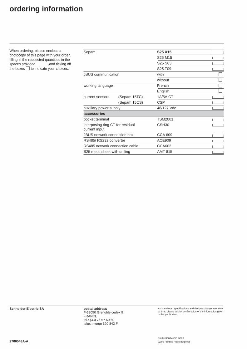
When ordering, please enclose aphotocopy of this page with your order,filling in the requested quantities in thespaces provided and ticking offthe boxes to indicate your choices.
ordering information
Sepam S25 X15
S25 M15
S25 S03
S25 T09
JBUS communication with
without
working language French
English
current sensors (Sepam 15TC) 1A/5A CT
(Sepam 15CS) CSP
auxiliary power supply 48/127 Vdc
accessories
pocket terminal TSM2001
interposing ring CT for residual CSH30current input
JBUS network connection box CCA 609
RS485/ RS232 converter ACE909
RS485 network connection cable CCA602
S25 metal sheet with drilling AMT 815