Embed Size (px)
DESCRIPTION
Manual Protección Catódica US Navy.
Citation preview
CHAPTER 19
CATHODIC PROTECTION SYSTEMS
S0600-AA-PRO-190
15 JUNE 1997
UNDERWATER SHIP HUSBANDRY MANUAL
0910-LP-730-7400
Published by direction of Commander, Naval Sea Systems Command
DISTRIBUTION STATEMENT A: This document has been approved for public release and sale; its
distribution is unlimited.
S0600-AA-PRO-190
A
Page No. * Change No.
Title and A . . . . . . . . . . . . . . . . . . . . . . . . 0Certification Sheet . . . . . . . . . . . . . . . . . . 0blank . . . . . . . . . . . . . . . . . . . . . . . . . . . . 0Flyleaf-1 (Flyleaf-2 blank) . . . . . . . . . . . . 0i through iii . . . . . . . . . . . . . . . . . . . . . . . . 0iv blank . . . . . . . . . . . . . . . . . . . . . . . . . . 0v through viii . . . . . . . . . . . . . . . . . . . . . . 0
LIST OF EFFECTIVE PAGES
Page No. * Change No.
19-1 through 19-11 . . . . . . . . . . . . . . . . . 019-12 blank . . . . . . . . . . . . . . . . . . . . . . . 019-13 through 19-41 . . . . . . . . . . . . . . . . 019-42 blank . . . . . . . . . . . . . . . . . . . . . . . 0A-1 through A-2. . . . . . . . . . . . . . . . . . . . 0B-1 through B-8. . . . . . . . . . . . . . . . . . . . 0
NAVSEA TECHNICAL MANUAL CERTIFICATION SHEET
Certification Applies to:
Applicable TMINS/Pub. No.
Publication Date (Da, Mo, Yr)
Title: Chapter 19, Cathodic Protection
TMCR/TMSR/Specification No.:
CHANGES AND REVISIONS:
CERTIFICATION STATEMENT
Purpose:
Equipment Alteration Numbers Incorporated:
TMDER/ACN Numbers Incorporated:
Continue on reverse side or add pages as needed.
New Manual Revision Change
of
This is to certify that responsible NAVSEA activities have reviewed the above identifieddocument for acquisition compliance, technical coverage, and printing quality. This form isfor internal NAVSEA management use only, and does not imply contractual approval oracceptance of the technical manual by the Government, nor relieve the contractor of anyresponsibility for delivering the technical manual in accordance with the contract require-ment.
Authority
Acquisition
Technical
PrintingRelease
DERIVED FROM NAVSEA 4160/8 (5 - 89)
Name Signature Organization Code Date
X
S0600-AA-PRO-190
15 June 1997
M. S. DEAN 00C5
00C57
NAVSEA
NAVSEA
1 1
A. BLAKEY
RECORD OF CHANGES
S0600-AA-PRO-190
CHANGE
NO.
DATE
OF
CHANGE
ENTERED
BYTITLE AND/OR BRIEF DESCRIPTION
Flyleaf-1/(Flyleaf-2 blank)

S0600-AA-PRO-190
i
TABLE OF CONTENTS
Paragraph Page
SECTION 1 INTRODUCTION
19-1.1 PURPOSE . . . . . . . . . . . . . . . . . . . . . . . . . . . . . . . . . . . . . . . . . . . . . . . . . . . . . . . 19-1
19-1.2 SCOPE. . . . . . . . . . . . . . . . . . . . . . . . . . . . . . . . . . . . . . . . . . . . . . . . . . . . . . . . . . 19-1
19-1.3 APPLICABILITY . . . . . . . . . . . . . . . . . . . . . . . . . . . . . . . . . . . . . . . . . . . . . . . . . . . 19-1
19-1.4 PRINCIPLES OF CATHODIC PROTECTION SYSTEMS . . . . . . . . . . . . . . . . . . . 19-1
19-1.4.1 Theory of Corrosion . . . . . . . . . . . . . . . . . . . . . . . . . . . . . . . . . . . . . . . 19-1
19-1.4.2 The Galvanic Series . . . . . . . . . . . . . . . . . . . . . . . . . . . . . . . . . . . . . . . 19-1
19-1.4.3 The Principle of the Impressed Current Cathodic Protection System. . 19-2
19-1.4.4 Anti-Corrosion Paint . . . . . . . . . . . . . . . . . . . . . . . . . . . . . . . . . . . . . . . 19-2
19-1.4.5 Hull Areas Most Likely to Corrode . . . . . . . . . . . . . . . . . . . . . . . . . . . . 19-2
19-1.4.6 The Hull-Mounted Components of the ICCP System . . . . . . . . . . . . . . 19-3
SECTION 2 PLANNING AND PREPARATION
19-2.1 GENERAL INFORMATION . . . . . . . . . . . . . . . . . . . . . . . . . . . . . . . . . . . . . . . . . . 19-9
19-2.1.1 Isolation of the ICCP System . . . . . . . . . . . . . . . . . . . . . . . . . . . . . . . . 19-9
19-2.1.2 Identifying the Task . . . . . . . . . . . . . . . . . . . . . . . . . . . . . . . . . . . . . . . 19-9
19-2.2 REFERENCE DOCUMENTS. . . . . . . . . . . . . . . . . . . . . . . . . . . . . . . . . . . . . . . . . 19-9
19-2.2.1 Ship Drawing Index . . . . . . . . . . . . . . . . . . . . . . . . . . . . . . . . . . . . . . . 19-9
19-2.2.3 Technical Manuals . . . . . . . . . . . . . . . . . . . . . . . . . . . . . . . . . . . . . . . 19-10
19-2.2.4 Military Specifications and Standards. . . . . . . . . . . . . . . . . . . . . . . . . 19-10
19-2.2.5 Records and Reports . . . . . . . . . . . . . . . . . . . . . . . . . . . . . . . . . . . . . 19-10
19-2.3 SHIP CHECK . . . . . . . . . . . . . . . . . . . . . . . . . . . . . . . . . . . . . . . . . . . . . . . . . . . . 19-10
19-2.4 INSPECTION DIVE . . . . . . . . . . . . . . . . . . . . . . . . . . . . . . . . . . . . . . . . . . . . . . . 19-10
19-2.5 CHOOSING THE APPROPRIATE ANODE REPLACEMENT PROCEDURE . . . 19-11
19-2.6 TYPICAL REPAIR TASK DURATION . . . . . . . . . . . . . . . . . . . . . . . . . . . . . . . . . 19-11
19-2.7 TOOLS, MATERIALS, AND EQUIPMENT REQUIREMENTS. . . . . . . . . . . . . . . 19-11
SECTION 3 INSPECTION
19-3.1 GENERAL . . . . . . . . . . . . . . . . . . . . . . . . . . . . . . . . . . . . . . . . . . . . . . . . . . . . . . 19-13
19-3.2 INSPECTION PROCEDURES. . . . . . . . . . . . . . . . . . . . . . . . . . . . . . . . . . . . . . . 19-13
19-3.2.1 Inspection Dive Considerations . . . . . . . . . . . . . . . . . . . . . . . . . . . . . 19-13
19-3.2.2 Anode and Dielectric Shield Inspection . . . . . . . . . . . . . . . . . . . . . . . 19-15
SECTION 4 REPAIRS
19-4.1 INTRODUCTION . . . . . . . . . . . . . . . . . . . . . . . . . . . . . . . . . . . . . . . . . . . . . . . . . 18-17
19-4.2 ANODE REMOVAL AND REPLACEMENT PROCEDURE - DRY. . . . . . . . . . . . 18-17
S0600-AA-PRO-190
ii
19-4.2.1 Anode Removal . . . . . . . . . . . . . . . . . . . . . . . . . . . . . . . . . . . . . . . . . 19-17
19-4.2.2 Anode Replacement . . . . . . . . . . . . . . . . . . . . . . . . . . . . . . . . . . . . . . 19-23
19-4.3 ANODE REMOVAL AND REPLACEMENT PROCEDURE - WET . . . . . . . . . . . 19-26
19-4.3.1 Anode Removal . . . . . . . . . . . . . . . . . . . . . . . . . . . . . . . . . . . . . . . . . 19-26
19-4.3.2 Anode Replacement . . . . . . . . . . . . . . . . . . . . . . . . . . . . . . . . . . . . . . 19-30
19-4.4 REFERENCE CELL REMOVAL AND REPLACEMENT PROCEDURE. 32
19-4.5 DIELECTRIC SHIELD REPAIRS. . . . . . . . . . . . . . . . . . . . . . . . . . . . . . . . . . . . . 19-38
19-4.6 POST-REPAIR PROCEDURES . . . . . . . . . . . . . . . . . . . . . . . . . . . . . . . . . . . . . 19-41
APPENDIX A: UNDERWATER EPOXY PAINTS
APPENDIX B: SETUP AND OPERATION OF THE SANDBLASTER
S0600-AA-PRO-190
iii
LIST OF ILLUSTRATIONS
Figure Page
19-1 Electromechanical Corrosion Cell . . . . . . . . . . . . . . . . . . . . . . . . . . . . . . . . . . . . . . . . 19-2
19-2 Basic Impressed Current Cathodic Protection System . . . . . . . . . . . . . . . . . . . . . . . . 19-3
19-3 Impressed Current Cathodic Protection System Units . . . . . . . . . . . . . . . . . . . . . . . . . 19-4
19-4 Anode. . . . . . . . . . . . . . . . . . . . . . . . . . . . . . . . . . . . . . . . . . . . . . . . . . . . . . . . . . . . . . 19-5
19-5 Reference Cell . . . . . . . . . . . . . . . . . . . . . . . . . . . . . . . . . . . . . . . . . . . . . . . . . . . . . . . 19-7
19-6 Capastic Dielectric Shield for a 4-Foot Anode . . . . . . . . . . . . . . . . . . . . . . . . . . . . . . . 19-8
19-7 Diver Hull Inspection Data Sheet . . . . . . . . . . . . . . . . . . . . . . . . . . . . . . . . . . . . . . . . 19-14
19-8 Anode Assembly . . . . . . . . . . . . . . . . . . . . . . . . . . . . . . . . . . . . . . . . . . . . . . . . . . . . 19-19
19-9 Anode Gland Assembly Internal Blanking Plate. . . . . . . . . . . . . . . . . . . . . . . . . . . . . 19-21
19-10 External Blanking Plate . . . . . . . . . . . . . . . . . . . . . . . . . . . . . . . . . . . . . . . . . . . . . . . 19-23
19-11 Reference Cell and Gland Seal Assembly . . . . . . . . . . . . . . . . . . . . . . . . . . . . . . . . . 19-33
19-13 Blanking Plug . . . . . . . . . . . . . . . . . . . . . . . . . . . . . . . . . . . . . . . . . . . . . . . . . . . . . . . 19-36
19-14 Guide Rod . . . . . . . . . . . . . . . . . . . . . . . . . . . . . . . . . . . . . . . . . . . . . . . . . . . . . . . . . 19-37
LIST OF TABLES
Table Page
19-1 Materials for Anode Replacement . . . . . . . . . . . . . . . . . . . . . . . . . . . . . . . . . . . . . . . 19-18
19-2 Materials for Reference Cell Replacement . . . . . . . . . . . . . . . . . . . . . . . . . . . . . . . . 19-32
19-12 High Hat . . . . . . . . . . . . . . . . . . . . . . . . . . . . . . . . . . . . . . . . . . . . . . . . . . . . . . . . . . . 19-35
19-3 Material for Dielectric Shield Repair . . . . . . . . . . . . . . . . . . . . . . . . . . . . . . . . . . . . . . 19-39

S0600-AA-PRO-190
iv
THIS PAGE INTENTIONALLY LEFT BLANK
S0600-AA-PRO-190
v
GENERAL SAFETY PRECAUTIONS. Thefollowing general safety precautions supple-ment the specific warnings and cautionsthroughout this chapter. These general pre-cautions are related to the task of underwatermaintenance of ship fitted Impressed CurrentCathodic Protection (ICCP) systems. In addi-tion to the following precautions, personnelmust be familiar with and observe safety pre-cautions set forth in the following publications.
a. Navy Occupational Safety and Health(NAVOSH) Program Manual for ForcesAfloat, OPNAVINST 5100.19 (series).
b. Naval Ships’ Technical Manual(NSTM).
c. Technical/operating manuals for equip-ment.
d. U.S. Navy Diving Manual, Volume I,NAVSEA 0944-LP-001-9010.
Do Not Repair or Adjust Alone.
Do not repair or adjust energized equipmentalone. The presence of a qualified individualcapable of rendering aid is required. Alwaysprotect against grounding hazards and makeadjustments with one hand free and clear ofequipment. Be aware that even after equip-ment has been de-energized, dangerous elec-trical hazards can exist due to capacitorsretaining electrical charges. Circuits must begrounded and capacitors discharged.
Test Equipment.
Make certain electrical test equipment is ingood condition and personnel are familiar withits safe operation. Handheld test equipmentmust be grounded, if possible, to preventshock injury. Since some types of equipmentcannot be grounded, avoid holding them toprevent injury.
Equipment in Motion.
Remain clear of equipment in motion. A safetywatch shall be posted if equipment requiresadjustment while in motion. The safety watchshall have full view of operations and immedi-ate access to controls that can stop the equip-ment. If at any time the auxiliary propulsionunit appears to be moving out of control, stopequipment immediately.
Limit Switches and Interlocks.
Limit switches and interlocks are provided toprotect personnel and equipment. Theyshould not be overridden or modified exceptby an authorized person. Do not dependsolely upon limit switches for protection. Dis-connect power at the power distributionsource before adjusting limit switches if possi-ble.
First Aid.
Attend to all injuries, however slight, by obtain-ing first aid or medical attention immediately.
Resuscitation.
Personnel working with or near high voltageshall be familiar with approved resuscitationmethods. Begin resuscitation immediately ifsomeone is injured and stops breathing. Adelay could cost the victim’s life. Resuscitationprocedures shall be posted where electricalhazards exist.
Minimizing Relative Motion.
Relative motion is the movement of two ormore objects in relation to each other. Thisposes unique hazards to divers. A commonexample is a nest of ships swaying and bounc-ing against each other due to wind and waveaction. This motion would easily crush a divercaught between the two ships. To reduce thehazards of relative motion and to simplify the
SAFETY SUMMARY
S0600-AA-PRO-190
vi
task, suspend the work platform and riggingfrom fittings on the ship.
WARNINGS AND CAUTIONS. Specific warn-ings and cautions appearing in this chapterare summarized below for emphasis andreview. The page number where each warningor caution appears is given in parentheses fol-lowing the warning or caution.
Underwater electrical equip-ment must be secured whiledivers are working over theside. Hull deterioration is mostsevere while the ICCP systemis de-energized and the effectsare irreversible. The appropri-ate zone of the ship’s ICCPsys tem mus t be secured ,tagged out , and confi rmedsecured before divers maywork on an I CCP dev i ce(anode, dielectric shield, or ref-erence cell). When divers arerequired to work in close prox-imity to an active ICCP anodeand risk of contact with ananode exists, that part of thesystem must be secured. Inother than these situations theICCP system is to remainactive. Divers working within 15feet of an active system mustwear a full dry suit, unisuit, orwet suit with hood and gloves.Clear communications amongdivers, surface personnel, andinboard ship’s force personnelare crucial for safe and effec-tive coordination of tasks andthe maintenance of watertightintegrity at through-hull pene-tration sites (pages 19-17, 19-26, 19-32, and 19-39).
Operators of sandblast ingequipment must be familiarwith and observe the Warningsand Cautions contained inAppendix B to this chapter(pages 19-22, 19-29, and 19-36).
Divers must wear protectiveheadgear and breathing appa-ratus while sandblasting insidethe habitat (page 19-22).
Epoxies, paints, and solventsare toxic and can cause seriousinjury to eyes and skin. Wearprotective goggles, coveralls,and impervious rubber glovesduring mixing and application.Epoxies, paints, and solventsemit toxic fumes. Ensure ade-quate ventilation for personnelduring mixing, application, orcleanup of tox ic mater ia ls(pages 19-24, 19-30, and 19-37).
Improper use o f the sand-blaster can be extremely haz-ardous (pages B-1 and B-5).
Always depressurize the blasttank whenever the unit is leftunattended (pages B-1 andB-5).
For safe operation the dead-man control switch should belocated not more than 6 inchesfrom the blast nozzle coupling(page B-2).
To prevent the operator fromreceiving static electricity gen-erated by the abrasive flow, theblast tank must be grounded(page B-3).
Topside personnel must wearear and eye protection when
WARNINGS
S0600-AA-PRO-190
vii
opera t ing the sandb laster(pages B-5).
Do not exceed 120 psi inlet airpressure (pages B-3 and B-5).
To prevent serious personnelinjury, Exercise extreme cautionwhen working around the sand-blaster when the tank is pres-surized (pages B-3 and B-4).
To prevent serious personnelin ju r y, check the sea l i ngplunger and sealing O-ringfrom a safe distance (pagesB-3 and B-5).
To prevent serious personnelinjury and equipment damage,do not point the blast nozzle atpersonnel or equipment (pagesB-4 and B-6).
Wearing a Mark 21 helmet, themaximum allowable time for adiver to operate the sand-blaster is five hours (page B-5).
Improper use o f the sand-blaster can be extremely haz-ardous (page B-5).
To prevent the operator fromreceiving static electricity gen-erated by abrasive flow, ensurethat the blast tank is properlygrounded (page B-5).
Never shut off the main air sup-ply to the blast tank until thetank is completely depressur-ized (page B-8).
To prevent serious personnelinjury, ensure that the main airsupply valve is shut and the airsupply hose is depressurizedbefore disconnecting (pageB-8).
It is essential that all tools andmaterials brought to the under-water job site are accounted forand removed at the completionof the job. Tools and materialsinadvertently left at the job sitecan generate unacceptablenoise and possibly cause se-vere damage to shipboardcomponents. Locally generatedwork packages shall ensurethat a general tool and materiallog sheet is prepared and main-tained during all UWSH opera-tions (page 19-11).
Removal of the anode requiresremoval of at least some of thedielectric shield around theanode. Great care should betaken to avoid cracking or oth-erwise damaging the existingshield. Additional shield dam-age will require removal andsubsequent additional applica-tion of epoxy (pages 19-21 and19-28).
The exposed anode securingstuds are used to mount thereplacement anode, and mustnot be damaged during sand-blasting or repair of the dielec-tric shield (pages 19-22 and 19-28).
Uneven or extreme tighteningof securing bolts will shatter theceramic surface of the anode(pages 19-24 and 19-30).
The careful application andsuccessful bonding of Capas-tic epoxy is crucial to the repair(pages 19-25 and 19-30).
CAUTIONS
S0600-AA-PRO-190
viii
Do not tighten the packing nutdown onto the top of the anodehub. If the correct number ofpacking rings have been fittedproperly, this should not bepossible (pages 19-25 and 19-31).
Capastic epoxy must be fullycured before the ICCP systemis tested (page 19-25).
Epoxy resin must be fully curedbefore the ICCP system istested. Depending on ambientwater temperatures, this couldtake several days (page 19-31).
Particular care must be exer-cised to protect the anode fromdamage during sandblasting(page 19-40).
Do not overtighten the blastnozzle when installing it on the
hose end threaded fitting. Donot use a wrench to tighten(page B-1).
The carbide nozzle is very frag-ile and shatters easily. Do notdrop or mishandle it (pages B-4and B-6).
To prevent accelerated wearon the plunger face and O-ring,do not overfill the blast tankwi th abrasive. The recom-mended level is no higher thanthe bottom edge of the sealingplunger (pages B-4 and B-7).
To preven t the ho se f rombecoming clogged with abra-sive, do not release the operat-ing handle on the deadmanswitch until all abrasive hasbeen discharged from the noz-zle (page B-7).
S0600-AA-PRO-190
19-1
19-1.1 PURPOSE.
This chapter provides commands with thetechnical information and NAVSEA-approvedprocedures for the underwater maintenance ofthe hull-mounted components of ship fittedImpressed Current Cathodic Protection(ICCP) systems. Strict adherence to the con-tents of this chapter will provide the bestassurance that all tasks are completed safelyand efficiently.
19-1.2 SCOPE.
The ICCP system is one of two equipmentsystems that use the principle of cathodic pro-tection to combat the electrochemical effectsof hull corrosion. The underwater mainte-nance of the other cathodic protection system,the Sacrificial Cathodic Protection system, isnot addressed in this chapter. UnderwaterShip Husbandry (UWSH) requires standard-ization of practices to ensure safe and cost-effective operations. This chapter providesNAVSEA-approved procedures and standard-ized instructions for the underwater inspec-tion, cleaning and maintenance of ICCPsystem reference cells, anodes and dielectricshields. This chapter also provides detailedplanning guidance for the installation of newreference cells, anodes, and dielectric shields.This chapter does not supersede informationcontained in the U.S. Navy Diving Manual orthe Naval Ships' Technical Manual (NSTM).
19-1.2.1 This chapter is divided into four sec-tions: an introduction to and description of theICCP system, planning and preparation,inspection, and repair procedures.
19-1.3 APPLICABILITY.
All personnel who are involved with the main-tenance of the hull components of the ICCPsystem must be familiar with the appropriatesections of this chapter. This includes not onlythe fleet diving lockers, but also the ship- andshore-based maintenance activities responsi-ble for the planning, implementation, and exe-cution of maintenance for the ship-fitted ICCPsystem.
19-1.4 PRINCIPLES OF CATHODIC PRO-TECTION SYSTEMS.
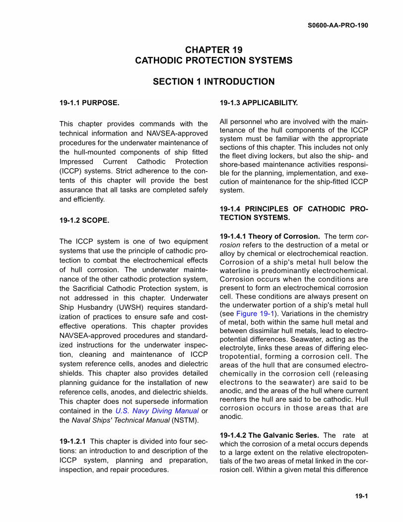
19-1.4.1 Theory of Corrosion. The term cor-rosion refers to the destruction of a metal oralloy by chemical or electrochemical reaction.Corrosion of a ship's metal hull below thewaterline is predominantly electrochemical.Corrosion occurs when the conditions arepresent to form an electrochemical corrosioncell. These conditions are always present onthe underwater portion of a ship's metal hull(see Figure 19-1). Variations in the chemistryof metal, both within the same hull metal andbetween dissimilar hull metals, lead to electro-potential differences. Seawater, acting as theelectrolyte, links these areas of differing elec-tropotential, forming a corrosion cell. Theareas of the hull that are consumed electro-chemically in the corrosion cell (releasingelectrons to the seawater) are said to beanodic, and the areas of the hull where currentreenters the hull are said to be cathodic. Hullcorrosion occurs in those areas that areanodic.
19-1.4.2 The Galvanic Series. The rate atwhich the corrosion of a metal occurs dependsto a large extent on the relative electropoten-tials of the two areas of metal linked in the cor-rosion cell. Within a given metal this difference
CHAPTER 19CATHODIC PROTECTION SYSTEMS
SECTION 1 INTRODUCTION
S0600-AA-PRO-190
19-2
is minimal. For dissimilar metals it is muchgreater. A measure of the electropotential dif-ferences between dissimilar metals is given inthe Galvanic Series (see NSTM Chapter 633).In a corrosion cell, the metal with the greaternegative electrical potential acts as theanode and will corrode.
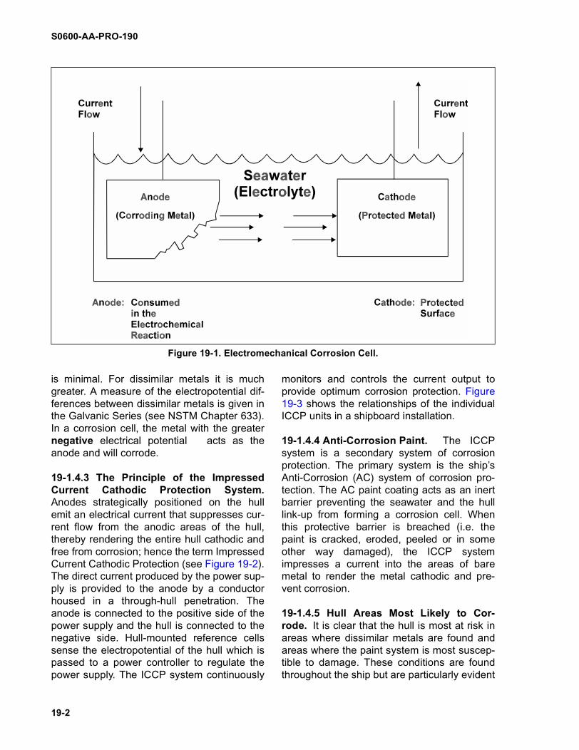
19-1.4.3 The Principle of the ImpressedCurrent Cathodic Protection System.Anodes strategically positioned on the hullemit an electrical current that suppresses cur-rent flow from the anodic areas of the hull,thereby rendering the entire hull cathodic andfree from corrosion; hence the term ImpressedCurrent Cathodic Protection (see Figure 19-2).The direct current produced by the power sup-ply is provided to the anode by a conductorhoused in a through-hull penetration. Theanode is connected to the positive side of thepower supply and the hull is connected to thenegative side. Hull-mounted reference cellssense the electropotential of the hull which ispassed to a power controller to regulate thepower supply. The ICCP system continuously
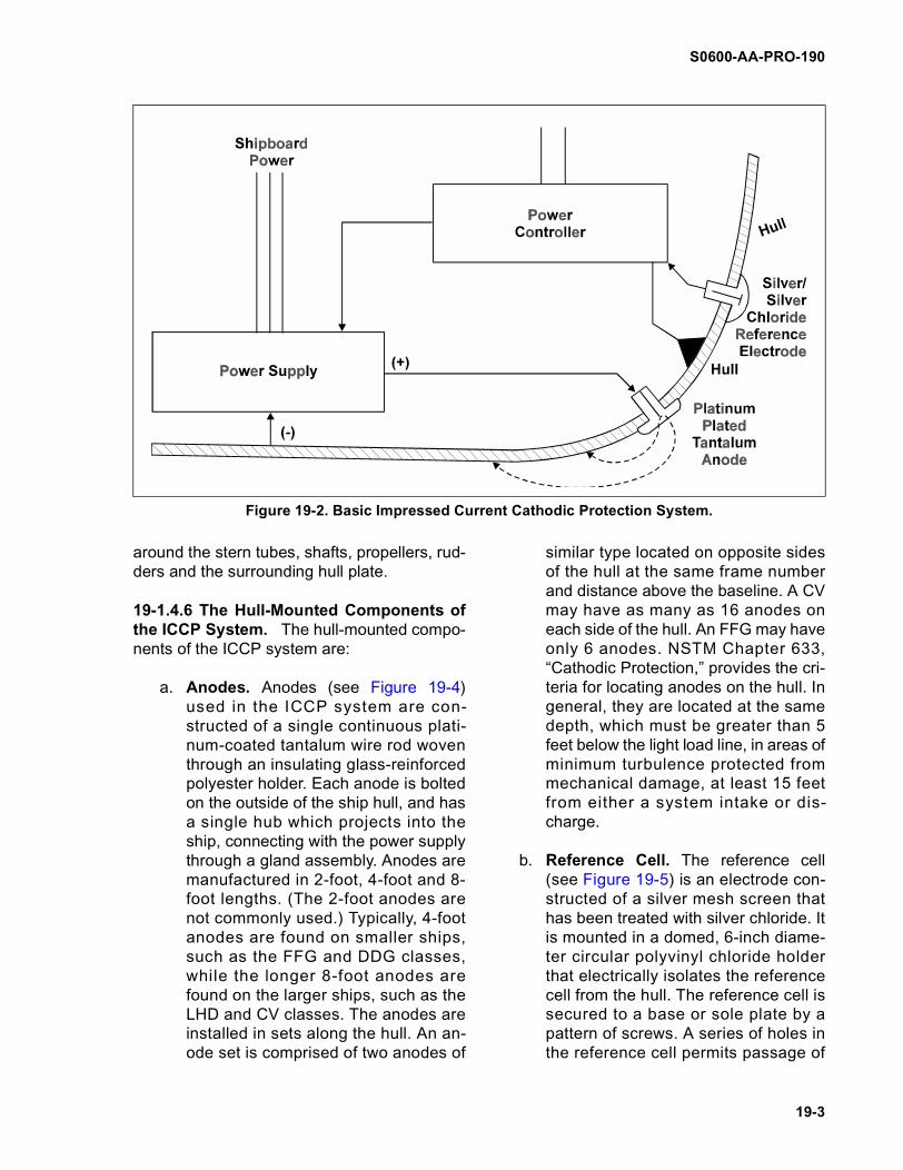
monitors and controls the current output toprovide optimum corrosion protection. Figure19-3 shows the relationships of the individualICCP units in a shipboard installation.
19-1.4.4 Anti-Corrosion Paint. The ICCPsystem is a secondary system of corrosionprotection. The primary system is the ship’sAnti-Corrosion (AC) system of corrosion pro-tection. The AC paint coating acts as an inertbarrier preventing the seawater and the hulllink-up from forming a corrosion cell. Whenthis protective barrier is breached (i.e. thepaint is cracked, eroded, peeled or in someother way damaged), the ICCP systemimpresses a current into the areas of baremetal to render the metal cathodic and pre-vent corrosion.
19-1.4.5 Hull Areas Most Likely to Cor-rode. It is clear that the hull is most at risk inareas where dissimilar metals are found andareas where the paint system is most suscep-tible to damage. These conditions are foundthroughout the ship but are particularly evident
Figure 19-1. Electromechanical Corrosion Cell.
S0600-AA-PRO-190
19-3
around the stern tubes, shafts, propellers, rud-ders and the surrounding hull plate.
19-1.4.6 The Hull-Mounted Components ofthe ICCP System. The hull-mounted compo-nents of the ICCP system are:
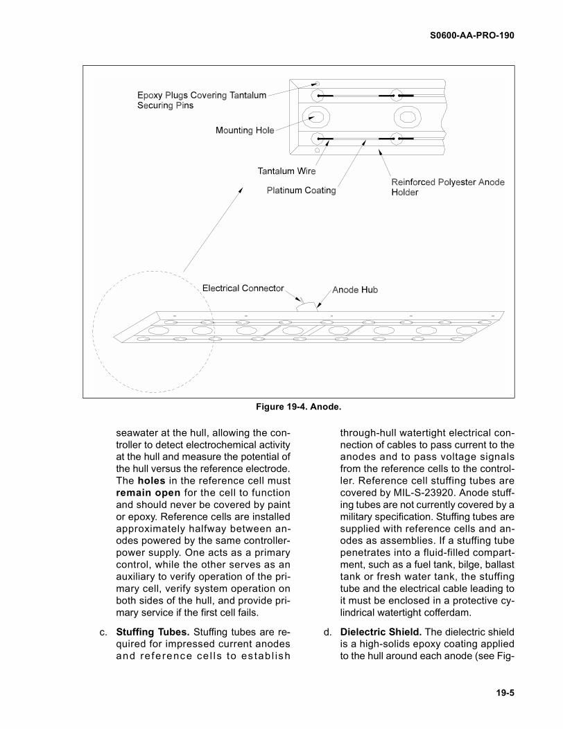
a. Anodes. Anodes (see Figure 19-4)used in the ICCP system are con-structed of a single continuous plati-num-coated tantalum wire rod woventhrough an insulating glass-reinforcedpolyester holder. Each anode is boltedon the outside of the ship hull, and hasa single hub which projects into theship, connecting with the power supplythrough a gland assembly. Anodes aremanufactured in 2-foot, 4-foot and 8-foot lengths. (The 2-foot anodes arenot commonly used.) Typically, 4-footanodes are found on smaller ships,such as the FFG and DDG classes,while the longer 8-foot anodes arefound on the larger ships, such as theLHD and CV classes. The anodes areinstalled in sets along the hull. An an-ode set is comprised of two anodes of
similar type located on opposite sidesof the hull at the same frame numberand distance above the baseline. A CVmay have as many as 16 anodes oneach side of the hull. An FFG may haveonly 6 anodes. NSTM Chapter 633,“Cathodic Protection,” provides the cri-teria for locating anodes on the hull. Ingeneral, they are located at the samedepth, which must be greater than 5feet below the light load line, in areas ofminimum turbulence protected frommechanical damage, at least 15 feetfrom either a system intake or dis-charge.
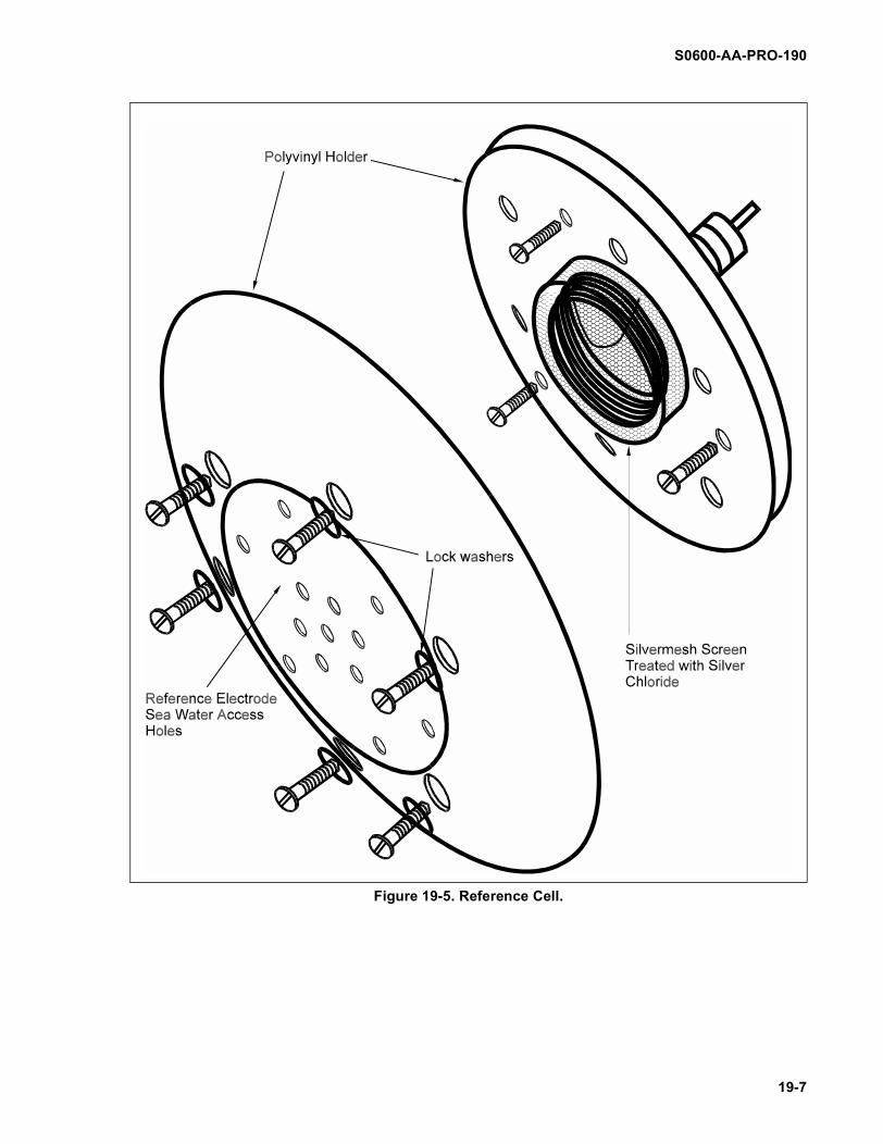
b. Reference Cell. The reference cell(see Figure 19-5) is an electrode con-structed of a silver mesh screen thathas been treated with silver chloride. Itis mounted in a domed, 6-inch diame-ter circular polyvinyl chloride holderthat electrically isolates the referencecell from the hull. The reference cell issecured to a base or sole plate by apattern of screws. A series of holes inthe reference cell permits passage of
Figure 19-2. Basic Impressed Current Cathodic Protection System.
S0600-AA-PRO-190
19-4
Figure 19-3. Impressed Current Cathodic Protection System Units.
S0600-AA-PRO-190
19-5
seawater at the hull, allowing the con-troller to detect electrochemical activityat the hull and measure the potential ofthe hull versus the reference electrode.The holes in the reference cell mustremain open for the cell to functionand should never be covered by paintor epoxy. Reference cells are installedapproximately halfway between an-odes powered by the same controller-power supply. One acts as a primarycontrol, while the other serves as anauxiliary to verify operation of the pri-mary cell, verify system operation onboth sides of the hull, and provide pri-mary service if the first cell fails.
c. Stuffing Tubes. Stuffing tubes are re-quired for impressed current anodesand re fe rence ce l ls to es tab l ish
through-hull watertight electrical con-nection of cables to pass current to theanodes and to pass voltage signalsfrom the reference cells to the control-ler. Reference cell stuffing tubes arecovered by MIL-S-23920. Anode stuff-ing tubes are not currently covered by amilitary specification. Stuffing tubes aresupplied with reference cells and an-odes as assemblies. If a stuffing tubepenetrates into a fluid-filled compart-ment, such as a fuel tank, bilge, ballasttank or fresh water tank, the stuffingtube and the electrical cable leading toit must be enclosed in a protective cy-lindrical watertight cofferdam.
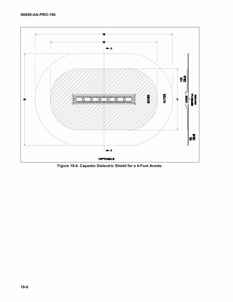
d. Dielectric Shield. The dielectric shieldis a high-solids epoxy coating appliedto the hull around each anode (see Fig-
Figure 19-4. Anode.
S0600-AA-PRO-190
19-6
ure 19-6). Dielectric shield areashave an inner shield area with athickness of 100 mils minimum anda thinner outer shield area with athickness of 22 mils minimum. For 4-foot anodes, inner shields extend to ar-eas of 7 feet by 10 feet, and outershields extend to areas 13 feet by 16feet, as measured from the anode. For8 foot anodes, inner shields extend toareas of 7 feet by 14 feet, and outershields extend to areas 13 feet by 20feet, as measured from the anode (seeFigure 19-6). The dielectric shield pre-vents shorting of the anode current to
the hull and aids in wider current distri-bution to the hull. Dielectric shieldmaterial is not covered by a militaryspecification. The current NAVSEA-approved dielectric shield material isCapastic, provided by Engelhard In-dustries. Capastic, however, can onlybe applied in dry dock or in a dry cham-ber (cofferdam). There are underwaterepoxies having excellent dielectric ca-pability that can be applied in water tomake repairs to damaged shields. Ap-pendix A to this chapter provides a listof approved epoxies.
S0600-AA-PRO-190
19-7
Figure 19-5. Reference Cell.
S0600-AA-PRO-190
19-8
Figure 19-6. Capastic Dielectric Shield for a 4-Foot Anode.
S0600-AA-PRO-190
19-9
19-2.1 GENERAL INFORMATION.
Planning is essential to the successful com-pletion of any underwater ship husbandrytask. Proper planning should begin at the ear-liest possible time, involve all concerned par-ties, and result in a written operational plan.General planning guidelines are presented inNAVSEA S0600-AA-PRO-020, General Infor-mation and Safety Precautions. While eachICCP maintenance task is unique, the require-ments of the planning process are identical.The following paragraphs list the requirementsthat need to be considered. They should beviewed as impacting three resource areas:technical, personnel and organizational.
19-2.1.1 Isolation of the ICCP System.Commands planning ICCP system mainte-nance tasks must be aware that any break inthe ICCP system will result in general corro-sion with all its manifestations, even thoughmost of the components may be completelycapable of their functions. In general, theICCP system should remain switched onwhenever possible. Guidance for switching offthe ICCP system to allow divers to work in thevicinity of ICCP hull fittings is detailed in theU.S. Navy Diving Manual and restated in thesafety summary to this chapter. The prudentimplementation of this policy will avoid theunnecessary replacement of defective ICCPhull-mounted fittings and reduce the risk ofcorrosion.
19-2.1.2 Identifying the Task. Componentsof an ICCP system may be defective for manyreasons and the significance of a defect on theoverall system effectiveness will vary. It maynot be necessary to conduct any maintenanceon a component that is clearly defective untilthe ship dry docks. It is important that the fac-tors relating to a defect are clearly and fullyunderstood; only then can the task be identi-fied and the correct maintenance decision betaken. In this respect a thorough inspection(both internal and external) is vital. ICCP sys-
tem inspections are addressed more fully insection 3.
19-2.2 REFERENCE DOCUMENTS.
Technical information and engineering dataessential to proper planning, preparation andexecution of ICCP system anode, referencecell, and dielectric shield repairs/replacementsare available in a variety of source documents.No single document provides all needed infor-mation. Care should be taken to obtain anduse the most current version of source docu-ments. They must be used during the planningphase and should be available on site duringthe conduct of the operation. NAVSEA S0600-AA-PRO-020 provides information on obtain-ing and using technical documents.
19-2.2.1 Ship Drawing Index. The S h ipDrawing Index (SDI), maintained in the ship'slog room or technical library, lists all the draw-ings applicable to that particular ship. Drawingnumbers are arranged in the SDI by functionalgroups and they are numerically listed withinthese groups. The docking plan, shell expan-sion, and lines drawing may be of particularvalue.
19-2.2.2 Electrocatalytic, Inc. is the sole pro-vider of U.S. Navy ship fitted ICCP systems.Their address is: Electrocatalytic, Inc., 2 Mill-town Court, Union, NJ 07083. The followingElectrocatalytic drawings are available onrequest from NAVSEA 00C5 and are valuablewhen planning and executing ICCP systemrepair and replacement:
a. 72800, Installation drawing, Anode 2 ft.
b. 36460-2L, Installation drawing, Anode4 ft.
c. 36460-2, Installation drawing, Anode 8ft.
d. 35754, Installation drawing, referenceelectrode assembly.
SECTION 2 PLANNING AND PREPARATION
S0600-AA-PRO-190
19-10
19-2.2.3 Technical Manuals. The Nava lShips' Technical Manual (NSTM) and othertechnical manuals provide operation andmaintenance information, personnel qualifica-tions, inspection criteria, technical and admin-istrative information, and instructions to assistin managing ship systems and equipment.The technical manuals and other materialsappl icable for ICCP system repair andreplacement are listed below:
a. S9086-VF-STM-010, NSTM Chapter633, “Cathodic Protection”
b. NAVSEA S0600-AA-PRO-160, Under-water Ship Husbandry Manual, Chap-ter 16, Cofferdams
c. NAVSEA S9086-CQ-STM-010, NSTMChapter 081, “Waterborne Hull Clean-ing of Navy Ships”
d. NAVSEA S9086-VD-STM-020, NSTMChapter 631 Volume 2, Preservation ofShips in Service - Surface Preparationand Painting.
e. NAVSEA S9086-CH-STM-030, NSTMChapter 074 Volume 3, “Gas Free En-gineering”
f. NAVSEA S0600-AA-PRO-170, Under-water Ship Husbandry Manual, Chap-ter 17, “Inspection Procedures”
19-2.2.4 Military Specifications and Stan-dards.
a. OPNAVINST 5100.19 (series), NavyOccupational Safety and Health (NA-VOSH) Program Manual for ForcesAfloat
b. SSPC-SP-10, Steel Structures PaintCouncil, Visual Standards for AbrasiveBlast Cleaned Steel
c. MIL-E-23919, Electrodes, Reference,Circular, Corrosion Preventive
d. MIL-S-24700, Stuffing Tubes for Refer-ence Electrodes, Impressed CurrentCathodic Protection
19-2.2.5 Records and Reports. The follow-ing records and reports, maintained in theship's log room, often provide important infor-mation on ICCP system components:
a. Underwater Repair/Working Reports.
b. Ship Maintenance/Repair Records.
c. Underwater Hull Inspection Reports.
d. Underwater Hull Cleaning Reports.
e. Diver Hull Inspection Data Sheet(NAVSEA Form 4730/7).
19-2.3 SHIP CHECK.
A ship check is required to establish liaisonwith the ship’s Engineering Officer and thework center with responsibility for the ICCPsystem. This allows the planner to retrieveinformation on conditions that may exist withthe ICCP system or an associated system thatcould affect the success of the repair. Theplanner should conduct a thorough internalinspection of the repair area for material con-dition, ease of access, and interference. If thecompartment in which the anode or referencecell gland assembly is located is an enclosedcompartment, consideration must be given tothe requirement of obtaining gas-free accessin accordance with NSTM 074 Volume 3, Sec-tion 20. In ballast and fuel tanks in particular,temporary scaffolding and lighting may berequired. In all situations, portable communi-cations must be established between person-nel working at the hull penetration, the divesupervisor, and, if appropriate, a safety sentrywho will be positioned at the entrance to theenclosed compartment. An external inspectionis required to determine accessibility to therepair area, positioning of the ship and theavailability of work area.
19-2.4 INSPECTION DIVE.
A thorough inspection dive must be conductedin advance of the repair task. The dive shouldidentify precisely the nature of the reporteddefect so that a proper assessment of therequired maintenance can be developed. Sec-
S0600-AA-PRO-190
19-11
tion 3 covers this matter in more detail. Thedive should also ascertain conditions at theunderwater work site. This is particularlyimportant if the resulting repair may requirethe use of a habitat. Detailed planning consid-erations for the use of habitats in support ofUWSH are given in NAVSEA S0600-AA-PRO-160, Cofferdams.
19-2.5 CHOOSING THE APPROPRIATEANODE REPLACEMENT PROCEDURE.
19-2.5.1 There are two anode replacementprocedures: a dry procedure and a wet proce-dure. The choice as to which is the mostappropriate procedure is governed largely bythe dielectric epoxy that is used to fair in thenew anode.
19-2.5.2 The dry procedure uses a habitat toenclose the anode, creating a dry environmentthat permits the use of the epoxy Capastic.The wet procedure does not use a habitat.This precludes the use of Capastic anddemands the use of an approved underwaterepoxy (see Appendix A).
19-2.5.3 The dry procedure is more costly inboth time and expense. The templating, con-struction, and fitting of the habitat combinedwith the requirement to maintain a dry environ-ment for the Capastic epoxy to cure, addsapproximately 48 hours to the repair task. Thedisadvantage of the wet procedure is the sen-sitivity of the underwater epoxy. It must bemixed exactly and the underlying hull pre-pared precisely. The epoxy, which is difficult toapply, must be adhered to the hull during avery narrow time window between epoxy mix-ing and hull preparation. Furthermore, under-water epoxy is unlikely to be appliedsuccessfully if the ambient temperature isbelow 50º F. In contrast, successful applica-tion of the epoxy Capastic is relatively easyand both cure times and the ease of applica-tion are independent of ambient temperature.
19-2.6 TYPICAL REPAIR TASK DURATION.
a. Anodes. Wet Procedure: One anodecan be replaced in 2-3 days, depen-dent on environmental conditions, i.e.epoxy cure times. Dry Procedure: Oneanode takes 4-5 days.
b. Reference Cells. One or two referencecells can be replaced in 2 days.
c. Dielectric Shield Repair. Dependent onthe extent of damage.
19-2.7 TOOLS, MATERIALS, AND EQUIP-MENT REQUIREMENTS.
It is essential that all tools andmaterials brought to the under-water job site are accounted forand removed at the completionof the job. Tools and materialsinadvertently left at the job sitecan generate unacceptablenoise and possibly cause se-vere damage to shipboardcomponents. Locally generatedwork packages shall ensurethat a general tool and materiallog sheet is prepared and main-tained during all UWSH opera-tions.
Removal and replacement of ICCP systemanodes and reference cells and repairs todielectric shields require the use of tools,materials, and equipment which should bemade available in advance. Table 19-1 (insection 4) provides a listing of the tools, mate-rials, and equipment required for anodereplacement. Table 19-2 provides the samefor reference cell replacement. Table 19-3 pro-vides the same for dielectric shield repair.
CAUTION

S0600-AA-PRO-190
19-12
THIS PAGE INTENTIONALLY LEFT BLANK

S0600-AA-PRO-190
19-13
19-3.1 GENERAL.
Diver inspection of the hull-mounted compo-nents of the ICCP system, reference cells,anodes, and dielectric shields is an essentialcomponent of the condition-based mainte-nance of the ICCP system.
19-3.1.1 Regular diver inspections will beconducted when a vessel receives a pro-grammed hull cleaning and on occasionswhen a systemic failure or other problem indi-cates a condition that requires underwaterexamination of the ICCP system.
19-3.1.2 The inspection dive can only be suc-cessful if the diver knows what to look for andunderstands the significance of the findings. Athorough pre-dive brief by a competent personis essential. This should include the relevantinformation distilled from: (i) a review of thelast inspection report (recorded on a Diver HullInspection Data Sheet NAVSEA Form 4730/7(Figure 19-7), which will provide a bench markfor system condition, and (ii) a brief from theship’s work center responsible for the ICCPsystem identifying any known problems.
19-3.1.3 Results from the inspection divemust be recorded on a Divers Hull InspectionData Sheet NAVSEA Form 4730/7 and ifappropriate supplemented by video or stillphotography. The form should be completedand, along with supporting data, forwarded tothe activity requesting the inspection, with acopy for the ship. On occasion the report willindicate that maintenance is required, such asdielectric shield, anode, or reference cellcleaning; dielectric shield repair; or anode andreference cell replacement. Technical guid-ance to support a proposed maintenance plancan be obtained from Fleet Technical SupportCenter, Atlantic, 9280 10th Avenue, Norfolk,VA 23511-4396; Fleet Technical Support Cen-ter, Pacific, Box 85548, San Diego, CA 92186-5540; or Naval Sea Systems Command (SEA03M or SEA 00C5). In such cases all of the
above inspection data, along with the relevantdata from the ship’s cathodic protection log(NAVSEA Form 9633/1) and any other rele-vant data must be made available to theabove technical authorities.
19-3.2 INSPECTION PROCEDURES.
Procedures for conducting an underwater shiphusbandry inspection are provided in NAV-SEA S0600-AA-PRO-170, Underwater ShipHusbandry Manual, Chapter 17. The followingparagraphs provide supplementary details.Figure 19-7 is an example of NAVSEA Form4730/7 that is used to record the results of allinspection dives on the ICCP system. A sepa-rate sheet of Form 4730/7 shall be used foreach anode/shield inspected.
19-3.2.1 Inspection Dive Considerations.The following are the factors and consider-ations that support the requirements of theDivers Hull inspection data sheet. A review ofthese considerations will help focus theinspection dive.
a. ICCP System Redundancy. Manyship-fitted ICCP systems are designedwith a degree of redundancy. By de-sign there are more anodes than arenecessary to provide full cathodic pro-tection. The importance of the ICCPsystem is as a backup to the anti-corro-sion (AC) paint scheme. It protects theship’s hull from the corrosion cell thatcould form in the event of a failure ofthe paint scheme In the free-flood ar-eas both of these conditions are likelyto be found.
b. Anode Location. Paragraph a. abovemakes it essential that the location ofthe anode and the condition of the paintscheme are accurately recorded duringan inspection.
c. Anode Redundancy. Each anode hasa degree of redundancy built in. If less
SECTION 3 INSPECTION

S0600-AA-PRO-190
19-14
Figure 19-7. Diver Hull Inspection Data Sheet.
S0600-AA-PRO-190
19-15
than 25 percent of the platinum coatedtantalum wires are broken, the anodecan still function satisfactorily. Simi-larly, up to 25 percent of each coatingof platinum can be missing and eachplatinum anode will still function cor-rectly.
d. Position of Broken Anode Wires. Be-cause each anode wire is a single con-tinuous loop running from the center ofthe anode to the outer edges, andpower to the anode comes from thecenter, a break in the wire becomesprogressively more significant thecloser it is to the center.
Points c. and d. make it essential thatthe position of a damaged wire and thetotal percentage of platinum coatingdamage are recorded.
e. Discoloration in The DielectricShield. The dielectric shield varies incolor. The dielectric epoxy, Capastic, isgray. If the shield has been repairedunderwater it may be another color(such as black). The overlying paintscheme can be many colors and thearea of the dielectric shield above andto the stern of the anode may appearbleached (a product of the caustic wa-ter chemistry created by the anode’soperation).
19-3.2.1.1 All of these patterns and color vari-ations are normal. In the past they have beenreported, erroneously, as evidence of electri-cal burning.
19-3.2.2 Anode and Dielectric ShieldInspection.
a. Begin the inspection procedure by con-ducting a cursory inspection of the an-ode, d ie lec t r i c sh ie ld and theimmediate hull out to a distance of 20feet. Identify obvious damage and as-sess the overall condition of the sys-tem. Record how long the anode has
been electrically isolated, i.e. de-ener-gized.
b. Conduct a detailed inspection of theanode.
(1) Record the Fouling Rating (FR),its nature (soft or hard calcare-ous, soft or hard marine fouling),and any differential fouling (suchas fouling just on the epoxy fillerabove the anode retaining nuts,or just on the tantalum wires).
(2) Inspect the tantalum wires:
(a) Ensure that all wires arepresent and count them.
(b) If wires are damaged (missing,broken, or bent), provide thefollowing details: position of thewire relative to the center of theanode and if the damage is inthat portion of the wire that iscoated with platinum.
(3) Inspect the platinum coating oneach wire:
(a) Ensure that none of the coatingis missing.
(b) Ensure that the coating istightly bonded to the wire.
(c) Check for discoloration, peel-ing, or bonding. Report all de-fects as a percentage of thetotal platinum coating.
(4) Inspect the glass-reinforced poly-ester holder:
(a) Check for damage, chips,dents, cracks or erosion and re-port the position relative to thecenter of the anode.
S0600-AA-PRO-190
19-16
(b) Confirm that the plugs of epoxythat cover the anode retainingnuts/bolts are secure and un-damaged.
c. Conduct a detailed inspection of the Di-electric Shield.
(1) Dielectric Shield - Anode Inter-face. This is the most critical areaof the dielectric shield. Examinethe area closely.
(a) Check that the dielectric shieldis evenly faired up to the top flatface of the anode.
(b) Confirm that a solid bond existsbetween the dielectric shieldand the anode holder.
(c) Check for cracks/chips or othersigns of damage in the dielec-tric shield.
(2) Dielectric Shield
(a) Record the location of all de-fects in the outer and innershield.
(b) Describe as either cracks, iso-lated pits/patches, flaking, oreroded, full or partial penetra-tion.
(c) Record the dimensions of eachdefect: total area, width andlength.
(d) Describe the pattern of cracks:radiating from the anode, cir-cumferential or irregular.
(e) Record the location of all foul-ing in the outer and inner shield(FR).
(f) Describe as either hard or softcalcareous fouling or hard orsoft marine growth.
(g) Record the dimensions of allgrowth.
S0600-AA-PRO-190
19-17
19-4.1 INTRODUCTION.
Divers are able to perform the following main-tenance tasks on the hull-mounted compo-nents of the ICCP system:
a. Anode Replacement: Depending onthe particular conditions of the task,this may be conducted either with ahabitat, using the dry procedure, orwithout a habitat, using the wet proce-dure.
b. Reference Cell Replacement
c. Dielectric Shield Repair
19-4.1.1 The detailed procedure for each ofthese repairs is included in this section.
NOTE
While the following proceduresrequire topside, Ship’s Force,and divers to work closelytogether, certain steps must becarried out by particular per-sonnel. To clarify these steps,abbreviations are placed at thebeginning of each step wherethe specific party needs to beidentif ied: (DV) representsdiver, (TOP) represents topsidepersonnel, and (SF) repre-sents Ship’s Force personnel.
19-4.2 ANODE REMOVAL AND REPLACE-MENT PROCEDURE - DRY.
19-4.2.1 Anode Removal.
Underwater electrical equip-ment must be secured whiledivers are working over theside. Hull deterioration is most
severe while the ICCP systemis de-energized and the effectsare irreversible. The appropri-ate zone of the ship’s ICCPsys tem mus t be secured ,tagged out , and confi rmedsecured before divers maywork on an I CCP dev i ce(anode, dielectric shield, or ref-erence cell). When divers arerequired to work in close prox-imity to an active ICCP anodeand risk of contact with ananode exists, that part of thesystem must be secured for theduration of the repair. In otherthan these situations the ICCPsystem is to remain active.Divers working within 15 feet ofan active system must wear afull dry suit, unisuit, or wet suitwith hood and gloves. Clearcommunications among divers,surface personnel, and inboardShip’s Force personnel are cru-cial for safe and effective coor-d ina t ion o f tasks and themaintenance of water t ightintegrity at through-hull pene-tration sites.
19-4.2.1.1 The activity conducting the anoderemoval and replacement shall:
a. Ensure all required materials are onhand using Table 19-1 for guidance.
b. Coordinate material, technical, andfunding requirements.
c. Conduct anode replacement training inaccordance with Naval Ships’ Techni-cal Manual, S9086-VF-STM-010/CH-633, “Cathodic Protection.”
d. Arrange with the ship for control anddisposal of hazardous material.
WARNING
SECTION 4 REPAIRS
S0600-AA-PRO-190
19-18
e. Prepare video and still cameras to doc-ument work throughout the procedure.Notify ship of any special precautionsrequired in the performance of re-moval/replacement.
19-4.2.1.2. The Ship’s Force shall:
a. Ensure that the ship is moored with theaffected anode toward the pier.
b. Tag out equipment and systems forconduct of diving operations.
c. Control and dispose of hazardous ma-terials as agreed with the performingactivity.
19-4.2.1.3. (SF) Defuel and gas free the com-partment / tank space in which the anode hullpenetration is located, and other compart-ments as necessary to access the anode con-nection box.
19-4.2.1.4. (SF) Rig lighting, and establishladders and scaffolding as necessary toaccess the anode.
19-4.2.1.5. (SF) If the anode hull penetrationis in an enclosed compartment, provide a sen-try in the nearest lit, ventilated compartmentwho is able to maintain verbal contact withworking personnel, especially if they are in anenclosed compartment.
19-4.2.1.6. (SF) Verify that the appropriatezone of the ICCP system has been de-ener-gized and tagged out. The rest of the ICCPsystem should remain energized.
NOTE
The de-energized zone wil lrema in de-energ i zed andtagged out until the epoxy iscured.
19-4.2.1.7. (SF, TOP, DV) Establish communi-cations between the inboard side of the anodehull penetration (Ship’s Force sentry), the divesupervisor, and the divers.
NOTE
The dive supervisor must besatisfied that the preparatorysteps 19-4.2.1.3 through 19-
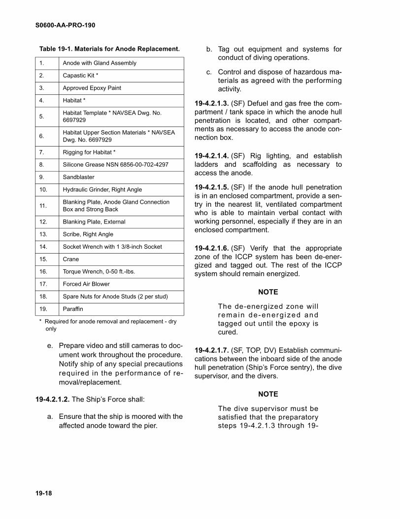
Table 19-1. Materials for Anode Replacement.
1. Anode with Gland Assembly
2. Capastic Kit *
3. Approved Epoxy Paint
4. Habitat *
5.Habitat Template * NAVSEA Dwg. No. 6697929
6.Habitat Upper Section Materials * NAVSEA Dwg. No. 6697929
7. Rigging for Habitat *
8. Silicone Grease NSN 6856-00-702-4297
9. Sandblaster
10. Hydraulic Grinder, Right Angle
11.Blanking Plate, Anode Gland Connection Box and Strong Back
12. Blanking Plate, External
13. Scribe, Right Angle
14. Socket Wrench with 1 3/8-inch Socket
15. Crane
16. Torque Wrench, 0-50 ft.-lbs.
17. Forced Air Blower
18. Spare Nuts for Anode Studs (2 per stud)
19. Paraffin
* Required for anode removal and replacement - dry only
S0600-AA-PRO-190
19-19
4.2.1.7 have been completedbefore proceeding.
NOTE
Templating of the hull, top sec-tion construction, rigging andplacement of the habitat shouldbe done as early in the proce-dure as possible, independentof the internal Ship’s Forceactions. Guidance for this taskis provided in NAVSEA 0600-
AA-PRO-016, Underwater ShipHusbandry Manual, Chapter16, “Cofferdams.”
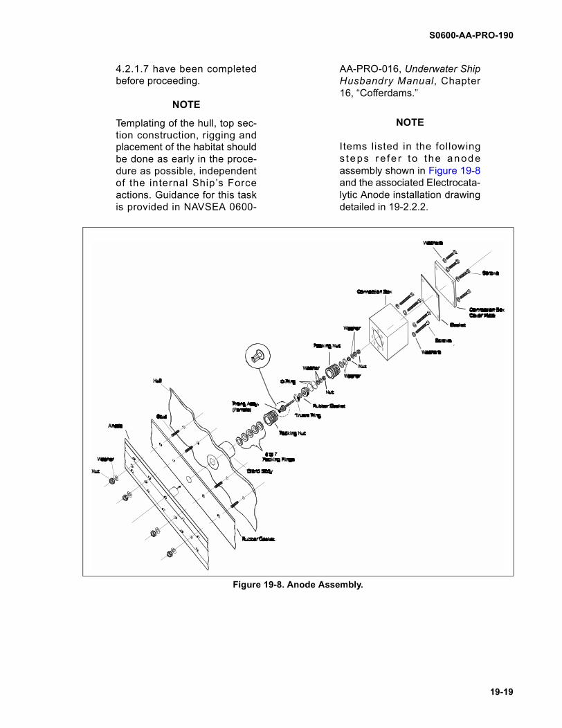
NOTE
Items listed in the followings teps re fe r to the anodeassembly shown in Figure 19-8and the associated Electrocata-lytic Anode installation drawingdetailed in 19-2.2.2.
Figure 19-8. Anode Assembly.
S0600-AA-PRO-190
19-20
NOTE
The actions in paragraphs 19-4.2.1.8 through 19-4.2.1.10 arerequired only if the anode con-nection box is located within atank or void space.
19-4.2.1.8 (SF) Remove the cover plate of theanode cell high-hat cofferdam.
19-4.2.1.9 (SF) Remove and inspect the high-hat cofferdam gasket. Replace the gasket ifnecessary.
19-4.2.1.10 (SF) Inspect the inside of thehigh-hat cofferdam for signs of corrosion orseepage of fuel or water. If there are suchsigns, determine the cause and if possible,rectify the defect.
NOTE
If the problem of liquid seepageinto the cofferdam can not becorrected, Ship’s Force shouldbe noti f ied and a decis ionmade whether or not to con-tinue with the anode replace-ment. If the root cause of adefective anode can not be cor-rected, replacement of theanode is of questionable value.
19-4.2.1.11 (SF) Ensure the ship is taggedout for diving.
19-4.2.1.12 (SF) Remove the electrical con-nection box cover.
19-4.2.1.13 (SF) Using a scribe or flat bladescrewdriver, carefully remove the paraffin frominside of the electrical connection box, ifpresent. Using a forced air blower, melt theremaining traces of paraffin to assist in itsremoval. Remove the nut, lock washer anddisconnect the terminal lug. Then remove theelectrical cable, flat washer, second nut, flatwasher and insulating washer.
19-4.2.1.14 (SF) Remove the connectionbox.
19-4.2.1.15 (SF) Remove the gland gasket.
19-4.2.1.16 (SF) Remove the packing nutusing a 1 3/8-inch socket wrench
19-4.2.1.17 (SF) Remove the female prongassembly.
19-4.2.1.18 (SF) Remove the truarc ring.
19-4.2.1.19 (SF) Remove the packing nut.
NOTE
The Teflon packing rings cannot be removed at this stagebecause of the restrictive forceof the anode hub.
19-4.2.1.20 (SF) Inspect the internal bore ofthe anode gland for corrosion and roughness.Clean as necessary. Coat the anode glandbody with silicone grease.
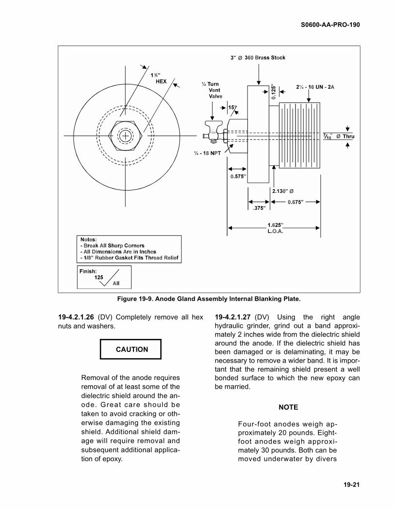
19-4.2.1.21 (SF) Fit the anode gland assem-bly internal blanking plate (Figure 19-9). Openand shut the vent valve of the blanking plate.
19-4.2.1.22 (TOP, DV) Rig and lower the hab-itat template to the hull and adjust dowels to fitthe anode location site. Return template to thesurface and use measurements taken to con-struct the top section of the habitat.
19-4.2.1.23 (TOP, DV) Rig and lower thecompleted habitat to the hull and secure. De-water the habitat to create a dry environment.
19-4.2.1.24 (DV) Remove the fairing epoxyfrom the anode securing nuts, using a ham-mer and chisel. Two-foot anodes have fourmounting holes for the threaded weld studsand securing hex nuts. Four-foot anodes have8 mounting holes for the threaded weld studsand securing hex nuts. Eight-foot anodes have16 mounting holes for studs, nuts, and wash-ers.
19-4.2.1.25 (DV) Working from the center out-ward, loosen hex nuts, one turn at a time.
S0600-AA-PRO-190
19-21
19-4.2.1.26 (DV) Completely remove all hexnuts and washers.
Removal of the anode requiresremoval of at least some of thedielectric shield around the an-ode. Great care should betaken to avoid cracking or oth-erwise damaging the existingshield. Additional shield dam-age will require removal andsubsequent additional applica-tion of epoxy.
19-4.2.1.27 (DV) Using the right anglehydraulic grinder, grind out a band approxi-mately 2 inches wide from the dielectric shieldaround the anode. If the dielectric shield hasbeen damaged or is delaminating, it may benecessary to remove a wider band. It is impor-tant that the remaining shield present a wellbonded surface to which the new epoxy canbe married.
NOTE
Four-foot anodes weigh ap-proximately 20 pounds. Eight-foot anodes weigh approxi-mately 30 pounds. Both can bemoved underwater by divers
Figure 19-9. Anode Gland Assembly Internal Blanking Plate.
CAUTION
S0600-AA-PRO-190
19-22
without additional lifting equip-ment.
19-4.2.1.28 (DV) Using wooden wedges asappropriate, remove the anode from the hull.Recover the anode to the surface.
19-4.2.1.29 (DV) Pass the anode to the diversfor transport to the habitat. Fit the anodeloosely over the studs to ensure it fits cor-rectly. If it does not, mark the top of the anodewhere it rubs and return it to the surface. Ifnecessary, carefully file away the minimumamount of ceramic necessary to fit the anodeover the studs. (See Figure 19-8.) On comple-tion, make sure that the washers on the studsstill provide adequate overlap on the enlargedhole.
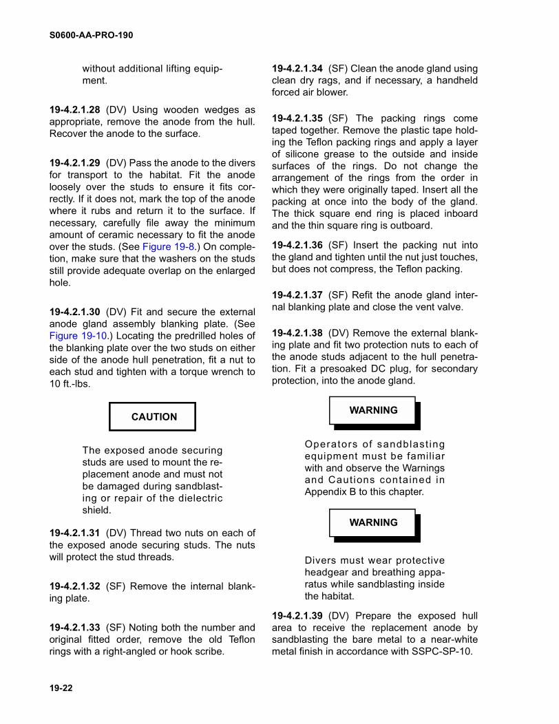
19-4.2.1.30 (DV) Fit and secure the externalanode gland assembly blanking plate. (SeeFigure 19-10.) Locating the predrilled holes ofthe blanking plate over the two studs on eitherside of the anode hull penetration, fit a nut toeach stud and tighten with a torque wrench to10 ft.-lbs.
The exposed anode securingstuds are used to mount the re-placement anode and must notbe damaged during sandblast-ing or repair of the dielectricshield.
19-4.2.1.31 (DV) Thread two nuts on each ofthe exposed anode securing studs. The nutswill protect the stud threads.
19-4.2.1.32 (SF) Remove the internal blank-ing plate.
19-4.2.1.33 (SF) Noting both the number andoriginal fitted order, remove the old Teflonrings with a right-angled or hook scribe.
19-4.2.1.34 (SF) Clean the anode gland usingclean dry rags, and if necessary, a handheldforced air blower.
19-4.2.1.35 (SF) The packing rings cometaped together. Remove the plastic tape hold-ing the Teflon packing rings and apply a layerof silicone grease to the outside and insidesurfaces of the rings. Do not change thearrangement of the rings from the order inwhich they were originally taped. Insert all thepacking at once into the body of the gland.The thick square end ring is placed inboardand the thin square ring is outboard.
19-4.2.1.36 (SF) Insert the packing nut intothe gland and tighten until the nut just touches,but does not compress, the Teflon packing.
19-4.2.1.37 (SF) Refit the anode gland inter-nal blanking plate and close the vent valve.
19-4.2.1.38 (DV) Remove the external blank-ing plate and fit two protection nuts to each ofthe anode studs adjacent to the hull penetra-tion. Fit a presoaked DC plug, for secondaryprotection, into the anode gland.
Operators of sandblast ingequipment must be familiarwith and observe the Warningsand Cautions contained inAppendix B to this chapter.
Divers must wear protectiveheadgear and breathing appa-ratus while sandblasting insidethe habitat.
19-4.2.1.39 (DV) Prepare the exposed hullarea to receive the replacement anode bysandblasting the bare metal to a near-whitemetal finish in accordance with SSPC-SP-10.
CAUTIONWARNING
WARNING
S0600-AA-PRO-190
19-23
NOTE
Capastic epoxy bonds mosteffectively to a slightly uneven(roughened) surface. A sand-blasted surface is ideal. Theedge of the dielectric shieldshould be faired by the sand-blaster to a 20-30 degree angleto receive the epoxy.
19-4.2.1.40 (DV) Sandblast the edge of theexisting dielectric shield to create a surface
suitable for subsequent fairing in of theCapastic epoxy.
19-4.2.2 Anode Replacement.
NOTE
Apply duct tape layers in pat-terns that both protect and areeasy to remove.
19-4.2.2.1 (TOP) Using duct tape, apply aprotective layer of strips sufficient to cover the
Figure 19-10. External Blanking Plate.

S0600-AA-PRO-190
19-24
outboard side of the replacement anode. Thiswill keep epoxy from fouling the anode sur-faces. Carefully cut out holes in the tape layercorresponding to the anode securing holes.The anode surface must be protected fromepoxy fouling but must also provide accessibil-ity to the securing studs. Fit a protective coverof duct tape over the male probe extendingfrom the anode hub.
Epoxies, paints, and solventsare toxic and can cause seriousinjury to eyes and skin. Wearprotective goggles, coveralls,and impervious rubber glovesduring mixing and application.Epoxies, paints, and solventsemit toxic fumes. Ensure ade-quate ventilation for personnelduring mixing, application, orcleanup of toxic materials.
19-4.2.2.2 (TOP) Cement the neoprene matto the anode by applying a layer of siliconerubber cement to one mat side and carefullylaying that side onto the anode, carefully guid-ing the anode hub through the mat hub hole.Ensure that the anode hub is not damaged,and the mat holes are aligned with the anodestud holes. The neoprene mat will not com-pletely cover the anode, and there will be anouter margin around the mat where the anodeis exposed. Apply a layer of silicone rubbercement around the edge of the neoprene mathull side, making sure not to plug the alignedstud holes.
19-4.2.2.3 (TOP) Apply a layer of Capasticepoxy to the exposed margin of the anodearound the mat, building up this margin to thesame height as the neoprene mat. TheCapastic should form a frame around andflush with the neoprene mat.
19-4.2.2.4 (DV) Remove the nuts protectingthe anode securing studs. Remove the pre-soaked DC plug from the anode gland hullpenetration.
19-4.2.2.5 (TOP, DV) Place the preparedreplacement anode into two watertight plasticbags, and pass the anode to the divers fortransport into the habitat.
Epoxies, paints, and solventsare toxic and can cause seriousinjury to eyes and skin. Wearprotective goggles, coveralls,and impervious rubber glovesduring mixing and application.Epoxies, paints, and solventsemit toxic fumes. Ensure ade-quate ventilation for personnelduring mixing, application, orcleanup of toxic materials.
19-4.2.2.6 (DV) Remove the prepared anodefrom the plastic bags. Remove the duct tapecovering the male probe extending from theanode hub. Carefully locate the anode overthe securing studs so that the anode hubprojects into the anode gland hull penetration,and the securing studs project through theanode stud holes.
Uneven or extreme tighteningof securing bolts will shatter theceramic surface of the anode.
19-4.2.2.7 (DV) Place a washer and hex nuton each securing stud to hold the anode and,starting from the centermost studs, tighteneach nut using only moderate torque. Tightenall nuts evenly, waiting several minutesbetween successive tightenings to permit theCapastic to squeeze against the prepared hull
WARNING WARNING
CAUTION
S0600-AA-PRO-190
19-25
surface and flow out from the back of theanode. Tighten all nuts to a torque of 10 ft.-lbs.
The careful application andsuccessful bonding of Capas-tic epoxy is crucial to the repair.
19-4.2.2.8 (DV) Press the squeezed Capasticepoxy around the anode evenly, fairing in theanode and marrying the epoxy to the clean,roughened existing dielectric shield edge.Cover all metal hull areas. Add additionalCapastic as necessary to completely fill andfair the gap between the old shield and thereplacement anode. Evenly fill in any irregularor trimmed areas of dielectric shield so thatthe integrity of the shield is completelyrestored.
19-4.2.2.9 (DV) Apply Capastic epoxy to fillthe securing nut holes in the tape layer abovethe anode securing nuts, fairing the epoxy tothe upper surface of the anode. When allepoxy has been applied, carefully remove theduct tape from the anode. All epoxy must nowcure for 24 hours before being exposed towater.
19-4.2.2.10 (SF) Vent and remove the inter-nal blanking plate.
Do not tighten the packing nutdown onto the top of the anodehub. If the correct number ofpacking rings have been fittedproperly, this should not bepossible.
NOTE
When Teflon is compressed itwill creep, i.e. slowly distort andflow away from the compres-sive force. The Teflon packingrings are the primary watertight
seal. To ensure that the Teflonrings form an effective water-tight seal it is essential that thegland nut compressing theTeflon rings is retightened 24hours after the initial compres-sion.
19-4.2.2.11 (SF) Tighten the packing nut witha 1 3/8-inch socket wrench until the packing iscompressed to the limit. Retighten at intervalsuntil tight and the Teflon has creeped as far aspossible. Repeat the operation one hourlater and 24 hours later.
19-4.2.2.12 (SF) Assemble two O-rings to thefemale prong assembly. Lubricate the femaleprong assembly and O-rings with siliconegrease.
19-4.2.2.13 (SF) Install the truarc ring, femaleprong assembly and packing nut, then tightendown the packing nut.
19-4.2.2.14 (SF) Install the gland gasket andthe connection box.
19-4.2.2.15 (SF) Install the insulating wash-ers, washer, nut, washer, anode cable lug(with cable), lock washer, and nut.
19-4.2.2.16 (SF) Install the gasket for theconnection box cover and the connection boxcover.
19-4.2.2.17 (SF) For protection against water,hull penetrations may have connection boxesfitted with a fill hole. Fill the connection boxwith paraffin. Insert the pipe plug in the tappedfill hole.
19-4.2.2.18 (SF) Replace the high-hat coffer-dam cover (if in a void or tank).
Capastic epoxy must be fullycured before the ICCP systemis tested.
CAUTION
CAUTION
CAUTION
S0600-AA-PRO-190
19-26
19-4.2.2.19 (DV) Enter the habitat after the 24hour Capastic cure period, and visuallyinspect the epoxy applications. Confirm thatthe epoxy has cured and appears properlybonded to the existing dielectric shield.
19-4.2.2.20 (DV) When the Capastic cure hasbeen confirmed, the habitat must be floodedfor ICCP system testing, but not removed incase further repairs are necessary.
19-4.2.2.21 (SF) Energize the ICCP systemto assure the proper operation of the replace-ment anode. Procedures for inspection andadjustment of system operation following shut-down and testing replacement anodes areprovided in NSTM 633, Section 6.
19-4.2.2.22 (SF, DV) When proper ICCP sys-tem operation is confirmed, unrig the habitatfrom the hull and rerig to the crane for retrievalfrom the water. Photograph the final repair.Remove the ship tag out for the ICCP system.
19-4.3 ANODE REMOVAL AND REPLACE-MENT PROCEDURE - WET.
19-4.3.1 Anode Removal.
Underwater electrical equip-ment must be secured whiledivers are working over theside. Hull deterioration is mostsevere while the ICCP systemis de-energized and the effectsare irreversible. The appropri-ate zone of the ship’s ICCPsys tem mus t be secured ,tagged out , and confi rmedsecured before divers maywork on an I CCP dev i ce(anode, dielectric shield, or ref-erence cell). When divers arerequired to work in close prox-imity to an active ICCP anodeand risk of contact with an
anode exists, that part of thesystem must be secured for theduration of the repair. In otherthan these situations the ICCPsystem is to remain active.Divers working within 15 feet ofan active system must wear afull dry suit, unisuit, or wet suitwith hood and gloves. Clearcommunications among divers,surface personnel, and inboardShip’s Force personnel are cru-cial for safe and effective coor-d ina t ion o f tasks and t hemaintenance of water t ightintegrity at through-hull pene-tration sites.
19-4.3.1.1 The activity conducting the anoderemoval and replacement shall:
a. Ensure all required materials are onhand using Table 19-1 for guidance.
b. Coordinate material, technical, andfunding requirements.
c. Conduct anode replacement training inaccordance with Naval Ships’ Techni-cal Manual, S9086-VF-STM-010/CH-633, “Cathodic Protection.”
d. Arrange with the ship for control anddisposal of hazardous material.
e. Prepare video and still cameras to doc-ument work throughout the procedure.Notify ship of any special precautionsrequired in the performance of re-moval/replacement.
19-4.3.1.2 The Ship’s Force shall:
a. Ensure that the ship is moored with theaffected anode toward the pier.
b. Tag out equipment and systems forconduct of diving operations.
c. Control and dispose of hazardous ma-terials as agreed with the performingactivity.
WARNING
S0600-AA-PRO-190
19-27
19-4.3.1.3 (SF) Defuel and gas free the com-partment/tank space in which the anode hullpenetration is located, and other compart-ments as necessary to access the anode con-nection box.
19-4.3.1.4 (SF) Rig lighting and establish lad-ders as necessary to access the anode.
19-4.3.1.5 (SF) If the anode hull penetrationis in an enclosed compartment, provide a sen-try in the nearest lit, ventilated compartmentwho is able to maintain verbal contact withworking personnel, especially if they are in anenclosed compartment.
19-4.3.1.6 (SF) Verify that the appropriatezone of the ICCP system has been de-ener-gized and tagged out. The rest of the ICCPsystem should remain energized, ionizing thehull which improves the adhesion of aquaticepoxy resins
19-4.3.1.7 (SF, TOP, DV) Establish communi-cations between the inboard side of the anodehull penetration (Ship’s Force sentry), the divesupervisor, and the divers.
NOTE
The dive supervisor must besatisfied that preparatory steps19-4.3.1.3 through 19-4.3.1.7have been completed beforeproceeding.
NOTE
The actions in paragraphs 19-4.3.1.8 through 19-4.3.1.10 arerequired only if the anode con-nection box is located within atank or void space.
19-4.3.1.8 (SF) Remove the cover plate of theanode high-hat cofferdam.
19-4.3.1.9 (SF) Remove and inspect the high-hat cofferdam gasket. Replace the gasket ifnecessary.
19-4.3.1.10 (SF) Inspect the inside of thehigh-hat cofferdam for signs of corrosion orseepage of fuel or water. If there are suchsigns, determine the cause and if possible,rectify the defect.
NOTE
If the problem of liquid seepageinto the cofferdam cannot becorrected, Ship’s Force shouldbe noti f ied and a decis ionmade whether or not to con-tinue with the anode replace-ment. If the root cause of adefective anode can not be cor-rected, replacement of theanode is of questionable value.
19-4.3.1.11 (SF) Ensure the ship is taggedout for diving.
19-4.3.1.12 (SF) Remove the electrical con-nection box cover.
19-4.3.1.13 (SF) Using a scribe or flat bladescrewdriver, carefully remove the paraffin frominside of the electrical connection box, ifpresent. Using a forced air blower, melt theremaining traces of paraffin to assist in itsremoval. Remove the nut, lock washer anddisconnect the terminal lug. Then remove theelectrical cable, flat washer, second nut, flatwasher and insulating washer.
19-4.3.1.14 (SF) Remove the connectionbox.
19-4.3.1.15 (SF) Remove the gland gasket.
19-4.3.1.16 (SF) Remove the packing nutusing a 1 3/8-inch socket wrench.
19-4.3.1.17 (SF) Remove the female prongassembly.
19-4.3.1.18 (SF) Remove the truarc ring.
19-4.3.1.19 (SF) Remove the packing nut.
S0600-AA-PRO-190
19-28
NOTE
The Teflon packing rings cannot be removed at this stagebecause of the restrictive forceof the anode hub.
19-4.3.1.20 (SF) Inspect the internal bore ofthe anode gland for corrosion and roughness.Clean as necessary. Coat the anode glandbody with silicone grease.
19-4.3.1.21 (SF) Fit the anode gland assem-bly internal blanking plate (Figure 19-9). Openand shut the vent valve of the blanking plate.
19-4.3.1.22 (DV) Remove the fairing epoxyfrom the anode securing nuts, using a ham-mer and chisel. Two-foot anodes have 4mounting holes and securing nuts. Four-footanodes have 8 mounting holes and securingnuts, while eight foot anodes have 16-mount-ing holes and securing hex nuts.
Removal of the anode requiresremoval of at least some of thedielectric shield around the an-ode. Great care should betaken to avoid cracking or oth-erwise damaging the existingshield. Additional shield dam-age will require removal andsubsequent additional applica-tion of epoxy.
19-4.3.1.23 (DV) Using the right anglehydraulic grinder, grind out a band approxi-mately 2 inches wide from the dielectric shieldaround the anode. If the dielectric shield hasbeen damaged or is delaminating, it may benecessary to remove a wider band. It is impor-tant that the remaining shield present a wellbonded surface to which the new epoxy canbe married.
NOTE
Four-foot anodes weigh ap-proximately 20 pounds. Eight-foot anodes weigh approxi-mately 30 pounds. Both can bemoved underwater by diverswithout additional lifting equip-ment.
19-4.3.1.24 (DV) Using wooden wedges asappropriate, remove the anode from the hull.Transfer the anode to the surface.
19-4.3.1.25 (DV) Fit and secure the externalanode gland assembly blanking plate (Figure19-10). Locating the predrilled holes of theblanking plate over the two studs to either sideof the anode hull penetration, fit a nut to eachstud and tighten with a torque wrench to atorque of 10 ft.-lbs.
The exposed anode securingstuds are used to mount the re-placement anode, and must notbe damaged during sandblast-ing or repair of the dielectricshield.
19-4.3.1.26 (DV) Thread two nuts on each ofthe exposed anode securing studs. The nutswill protect the stud threads.
19-4.3.1.27 (SF) Open the vent valve on theanode gland internal blanking plug. Seawaterwhich entered the stuffing tube when theanode was removed may be present, but it isimportant to confirm that there is no leak ofseawater from the external blanking plate.When this has been confirmed, close thevalve and remove the blanking plate. Evacu-ate any water in the gland body.
CAUTION
CAUTION
S0600-AA-PRO-190
19-29
19-4.3.1.28 (SF) Noting both the number andoriginal fitted order, remove the old Teflonrings with a right-angled or hook scribe.
19-4.3.1.29 (SF) Clean the anode gland usingclean dry rags, and if necessary a hand-heldforced air blower.
19-4.3.1.30 (SF) Remove the plastic tapeholding the Teflon packing rings and apply alayer of silicone grease to the outside andinside surfaces of the rings. Do not change thearrangement of the rings from the order inwhich they were originally taped. Insert all thepacking at once into the body of the gland.The thick square end ring is placed inboardand the thin square ring is outboard.
19-4.3.1.31 (SF) Insert the packing nut intothe gland and tighten until the nut just touches,but does not compress, the Teflon packing.
19-4.3.1.32 (SF) Refit the anode gland inter-nal blanking plug and close the vent valve.
19-4.3.1.33 (DV) Remove the external blank-ing plate and fit two protection nuts to each ofthe anode studs adjacent to the hull penetra-tion.
19-4.3.1.34 (DV) Fit a pre-soaked DC pluginto the anode gland for protection during hullcleaning.
19-4.3.1.35 (DV) Fit the anode loosely overthe stud to confirm that it fits. If it does not,mark the anode where it rubs and return it tothe surface. If necessary, file away the mini-mum of ceramic to fit the anode over thestuds. (See Figure 19-8.) On completion,
make sure the washers on the studs still pro-vide adequate overlap on the enlarged hole.
Operators of sandblast ingequipment must be famil iarwith and observe the Warningsand Caut ions conta ined inAppendix B to this chapter.
19-4.3.1.36 (DV) Prepare the exposed hullarea to receive the replacement anode bysandblasting the bare metal to a near-whitemetal finish in accordance with SSPC-SP10.
NOTE
Most underwater epoxies bondmost effectively to a slightlyuneven (roughened) surface. Asandblasted surface is ideal.The edge of the d ie lec tr icshield should be faired by thesandblaster to a 20-30 degreeangle to receive the epoxy.
NOTE
The supervisor must ensurethat the time between surfacepreparation and epoxy paintapplication is kept to a mini-mum. If a prepared surface isleft for a lengthy period withoutpaint, it will begin to rust andthe surface wil l have to besandblasted again before paintapplication. Similarly, an oilyfilm can form in a very shorttime and prevent successfulpaint application. Wiping theprepared surface with a con-centrated detergent (“Joy”)
WARNING
S0600-AA-PRO-190
19-30
immediately before paint appli-cation can help the paint toadhere.
19-4.3.1.37 (DV) Sandblast the edge of theexisting dielectric shield to create a surfacesuitable for subsequent fairing in of theapproved epoxy (see Appendix A).
19-4.3.2 Anode Replacement.
NOTE
Apply duct tape layers in pat-terns that both protect and areeasy to remove.
19-4.3.2.1 (TOP) Using duct tape, apply aprotective layer of strips sufficient to cover thetop of the replacement anode. This will keepepoxy from fouling the anode surfaces. Care-fully cut out holes in the tape layer corre-sponding to the anode securing holes. Theanode surface must be protected from epoxyfouling but must also provide accessibility tothe securing studs. Fit a protective cover ofduct tape over the male probe extending fromthe anode hub.
Epoxies, paints, and solventsare toxic and can cause seriousinjury to eyes and skin. Wearprotective goggles, coveralls,and impervious rubber glovesduring mixing and application.Epoxies, paints, and solventsemit toxic fumes. Ensure ade-quate ventilation for personnelduring mixing, application, orcleanup of toxic materials.
19-4.3.2.2 (TOP) Apply a layer of epoxy tothe back of the anode, keeping a margin 1inch wide around the anode hub free of epoxy.Place the neoprene mat onto the anode care-fully, guiding the anode hub through the mathub hole. Ensure the anode hub is not dam-
aged and the mat holes are aligned withanode stud holes. The neoprene mat will notcompletely cover the anode and there will bean outer margin around the mat where theanode is exposed. Apply another layer ofepoxy to this exposed margin to build it to thesame level as the edge of the neoprene mat.
19-4.3.2.3 (DV) Remove the nuts protectingthe anode securing studs. Remove the pre-soaked DC plug from the hull penetration,exposing the stuffing tube.
19-4.3.2.4 (TOP, DV) Pass the preparedanode to the divers for transport to the hull.
19-4.3.2.5 (DV) Remove the duct tape cover-ing the male probe extending from the anodehub. Carefully locate the anode over thesecuring studs so that the anode hub projectsinto the stuffing tube, and the securing studsproject through the anode stud holes.
Uneven or extreme tighteningof securing bolts will shatter theceramic surface of the anodeholder.
19-4.3.2.6 (DV) Place a washer and hex nuton each securing stud to hold the anode and,starting from the centermost studs, tighteneach nut using only moderate torque. Tightenall nuts evenly, waiting several minutesbetween successive tightenings to permit theepoxy to squeeze against the prepared hullsurface and flow out from the back of theanode. Tighten all nuts to a torque of 10 ft.-lbs.
The careful application andsuccessful bonding of epoxy iscrucial to the repair.
19-4.3.2.7 (DV) Press the squeezed epoxyaround the anode evenly, fairing in the anode
WARNING
CAUTION
CAUTION
S0600-AA-PRO-190
19-31
and marrying the epoxy to the clean, rough-ened existing dielectric shield edge. Cover allmetal hull areas. Add additional 20 mil layersof epoxy as necessary to completely fill andfair the gap between the old shield and thereplacement anode. Evenly fill in any irregularor trimmed areas of dielectric shield so thatthe integrity of the shield is completelyrestored.
19-4.3.2.8 (DV) Apply the approved epoxy tofill the securing nut holes in the tape layerabove the anode securing nuts (8 or 16), fair-ing the epoxy to the upper surface of theanode. When all epoxy has been applied,carefully remove the duct tape from theanode. All epoxy must now cure at a ratedependent upon ambient water temperature(see the graph in Appendix A).
19-4.3.2.9 (SF) Vent and remove the internalblanking plate.
19-4.3.2.10 (SF) If necessary, clear theanode gland of any water with an air hose (awhip leading from a scuba bottle would beappropriate). Dry and recoat the gland with sil-icone grease.
NOTE
When Teflon is compressed itwill creep, i.e. slowly distort andflow away from the compres-sive force. The Teflon packingrings are the primary watertightseal. To ensure that the Teflonrings form an effective water-tight seal it is essential that thegland nut compressing theTeflon rings is retightened 24hours after the initial compres-sion.
Do not tighten the packing nutdown onto the top of the anodehub. If the correct number of
packing rings have been fittedproperly, this should not bepossible.
19-4.3.2.11 (SF) Tighten the packing nut witha 1 3/8-inch socket wrench until the packing iscompressed to the limit. Retighten at intervalsuntil tight and the Teflon has creeped as far aspossible. Repeat the operation one hourlater and 24 hours later.
19-4.3.2.12 (SF) Assemble two O-rings to thefemale prong assembly. Lubricate the femaleprong assembly and O-rings with siliconegrease.
19-4.3.2.13 (SF) Install the truarc ring, femaleprong assembly and packing nut, then tightendown the packing nut.
19-4.3.2.14 (SF) Install gland gasket, connec-tion box, gasket for the connection box cover,and the connection box cover.
19-4.3.2.15 (SF) Install insulating washers,washer, nut, washer, anode cable lug (withcable), lock washer, and nut.
19-4.3.2.16 (SF) For protection against water,hull penetrations may have connection boxesfitted with a fill hole. Fill the connection boxwith paraffin. Insert the pipe plug in the tappedfill hole.
19-4.3.2.17 (SF) Replace the high-hat coffer-dam cover if the connection box is located in atank or void space.
Epoxy must be fully cured be-fore the ICCP system is tested.Depending on ambient watertemperatures, this could takeseveral days.
19-4.3.2.18 (DV) After an adequate cureperiod, visually inspect the epoxy applications.Confirm that the epoxy has cured and appears
CAUTION
CAUTION
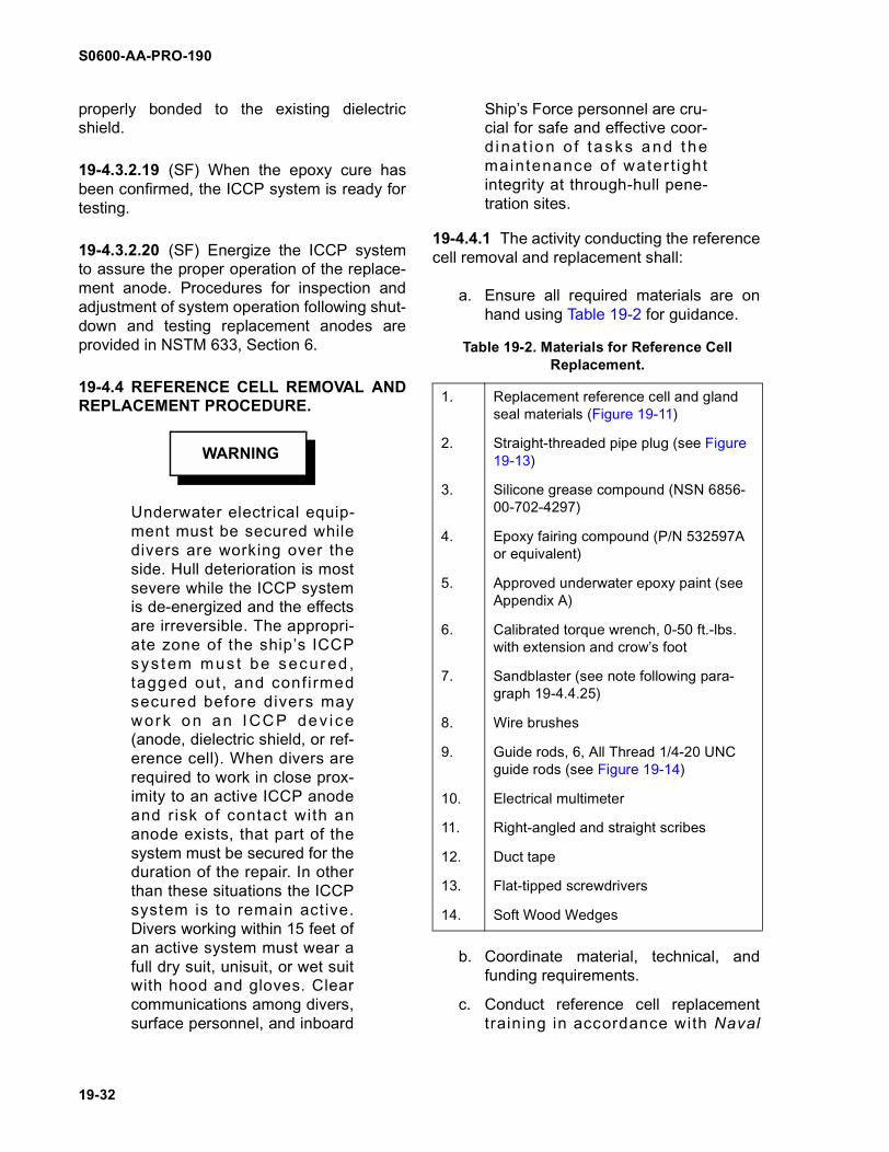
S0600-AA-PRO-190
19-32
properly bonded to the existing dielectricshield.
19-4.3.2.19 (SF) When the epoxy cure hasbeen confirmed, the ICCP system is ready fortesting.
19-4.3.2.20 (SF) Energize the ICCP systemto assure the proper operation of the replace-ment anode. Procedures for inspection andadjustment of system operation following shut-down and testing replacement anodes areprovided in NSTM 633, Section 6.
19-4.4 REFERENCE CELL REMOVAL ANDREPLACEMENT PROCEDURE.
Underwater electrical equip-ment must be secured whiledivers are working over theside. Hull deterioration is mostsevere while the ICCP systemis de-energized and the effectsare irreversible. The appropri-ate zone of the ship’s ICCPsys tem mus t be secured ,tagged out , and confi rmedsecured before divers maywork on an I CCP dev i ce(anode, dielectric shield, or ref-erence cell). When divers arerequired to work in close prox-imity to an active ICCP anodeand risk of contact with ananode exists, that part of thesystem must be secured for theduration of the repair. In otherthan these situations the ICCPsystem is to remain active.Divers working within 15 feet ofan active system must wear afull dry suit, unisuit, or wet suitwith hood and gloves. Clearcommunications among divers,surface personnel, and inboard
Ship’s Force personnel are cru-cial for safe and effective coor-d ina t ion o f tasks and t hemaintenance of water t ightintegrity at through-hull pene-tration sites.
19-4.4.1 The activity conducting the referencecell removal and replacement shall:
a. Ensure all required materials are onhand using Table 19-2 for guidance.
b. Coordinate material, technical, andfunding requirements.
c. Conduct reference cell replacementtraining in accordance with Naval
WARNING
Table 19-2. Materials for Reference Cell Replacement.
1. Replacement reference cell and gland seal materials (Figure 19-11)
2. Straight-threaded pipe plug (see Figure 19-13)
3. Silicone grease compound (NSN 6856-00-702-4297)
4. Epoxy fairing compound (P/N 532597A or equivalent)
5. Approved underwater epoxy paint (see Appendix A)
6. Calibrated torque wrench, 0-50 ft.-lbs. with extension and crow’s foot
7. Sandblaster (see note following para-graph 19-4.4.25)
8. Wire brushes
9. Guide rods, 6, All Thread 1/4-20 UNC guide rods (see Figure 19-14)
10. Electrical multimeter
11. Right-angled and straight scribes
12. Duct tape
13. Flat-tipped screwdrivers
14. Soft Wood Wedges
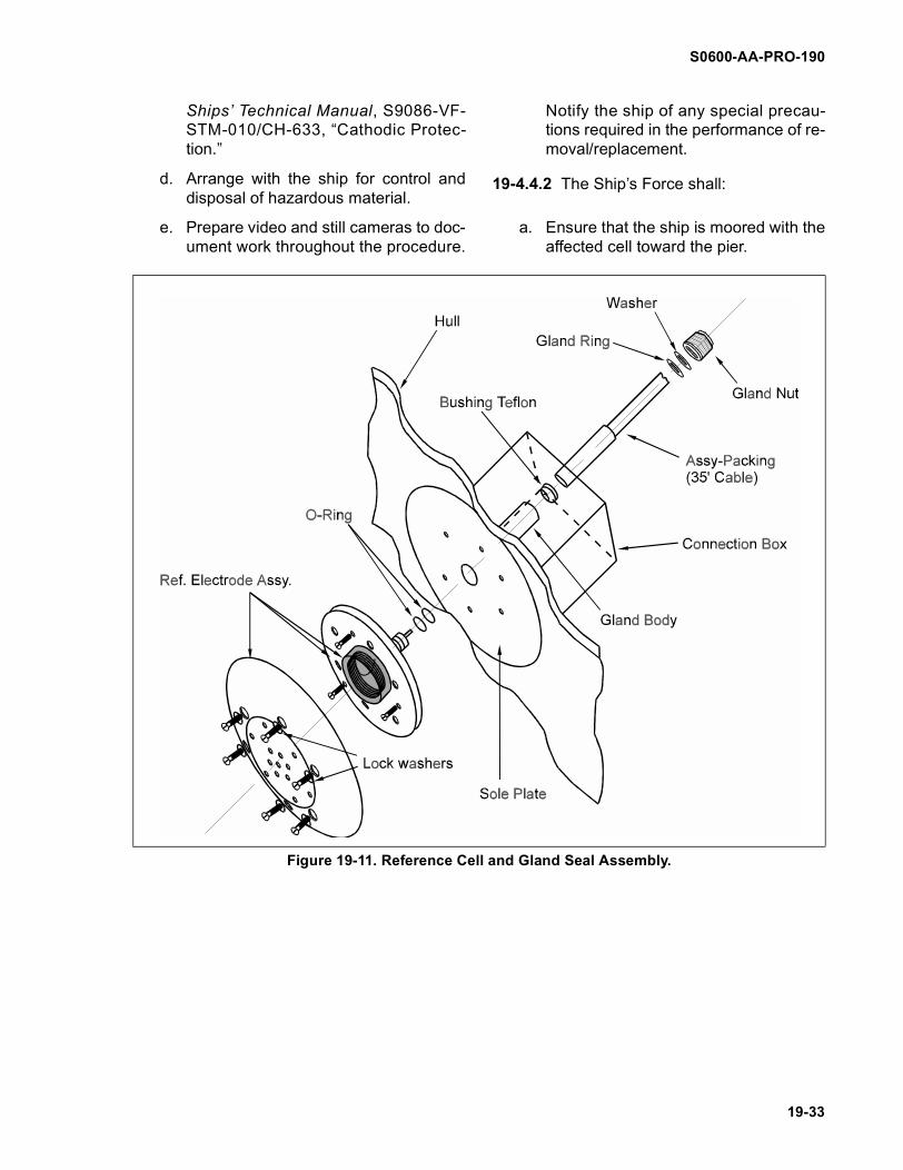
S0600-AA-PRO-190
19-33
Ships’ Technical Manual, S9086-VF-STM-010/CH-633, “Cathodic Protec-tion.”
d. Arrange with the ship for control anddisposal of hazardous material.
e. Prepare video and still cameras to doc-ument work throughout the procedure.
Notify the ship of any special precau-tions required in the performance of re-moval/replacement.
19-4.4.2 The Ship’s Force shall:
a. Ensure that the ship is moored with theaffected cell toward the pier.
Figure 19-11. Reference Cell and Gland Seal Assembly.

S0600-AA-PRO-190
19-34
b. Tag out equipment and systems forconduct of diving operations.
c. Control and dispose of hazardous ma-terial as agreed to with the performingactivity.
19-4.4.3 (SF) Defuel and gas free the com-partment in which the reference cell hull pene-tration is located, and other compartments asnecessary to access the reference cell (if thecell is located outboard of a tank/void).
19-4.4.4. (SF) Rig lighting and establish lad-ders and scaffolding as necessary to accessthe reference cell.
19-4.4.5. (SF) Provide a sentry at the refer-ence cell hull penetration who is able to main-tain verbal contact with working personnel,especially if they are in an enclosed compart-ment.
19-4.4.6. Verify that the appropriate zone ofthe ICCP system has been de-energized andtagged-out. The rest of the ICCP systemshould remain energized, ionizing the hull.
19-4.4.7. (SF, TOP, DV) Establish communi-cations between the inboard side of the refer-ence cell hull penetration (Ship’s Forcesentry), the dive supervisor, and the divers.
NOTE
The dive supervisor must besatisfied that the preparatorysteps 19-4.4.3 through 19-4.4.7have been completed beforeproceeding.
19-4.4.8 (SF) Remove the cover plate of thehigh-hat cofferdam housing the reference cellgland assembly (Figure 19-12).
19-4.4.9 (SF) Inspect and remove the high-hat cofferdam gasket. Replace the gasket ifnecessary.
19-4.4.10 (SF) Inspect the inside of the cof-ferdam/high hat for signs of corrosion orfuel/liquid ingress. If there are signs ascertainthe cause of the ingress and, if possible, rec-tify the defect.
NOTE
If the problem can not be recti-fied then a decision should bemade whether to continue withthe replacement while a poten-tial root cause for the defectivereference cell exists.
19-4.4.11 (SF) Remove the gland nut.Because of its position inside the high-hat cof-ferdam it is necessary to use a wrench with anextension piece and a crow’s foot with aninternal jaw diameter of 1 1/8 inch.
19-4.4.12 (SF) Remove the cable and pack-ing assembly by hand.
19-4.4.13 (SF) Determine if the Teflon bush-ing is still in place. If it is loose, remove it.
19-4.4.14 (SF) Inspect the walls of the glandbody for signs of water entry.
19-4.4.15 (SF) Fit a straight-threaded blank-ing plug into the gland body.
NOTE
The straight threaded blankingplug must be manufacturedlocally. It is fitted in place of thegland nut. It should be manu-factured with a 1/4 turn ventvalve and an O-ring, with a 1-inch 12 UNF-1A thread pattern(see Figure 19-13). The oldgland nut could be fitted with a1/2-inch male with plain endvent valve to make this blank-ing plug.
19-4.4.16 (DV) Remove the fairing epoxyfrom the six reference cell securing screwsusing a small hand-held chisel.
19-4.4.17. (DV) Using a flat tip screwdriver,loosen the six screws in a star pattern, givingeach screw one turn.
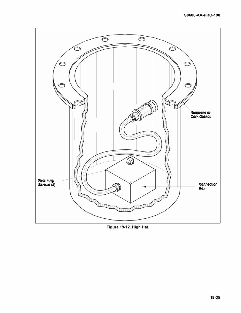
S0600-AA-PRO-190
19-35
Figure 19-12. High Hat.
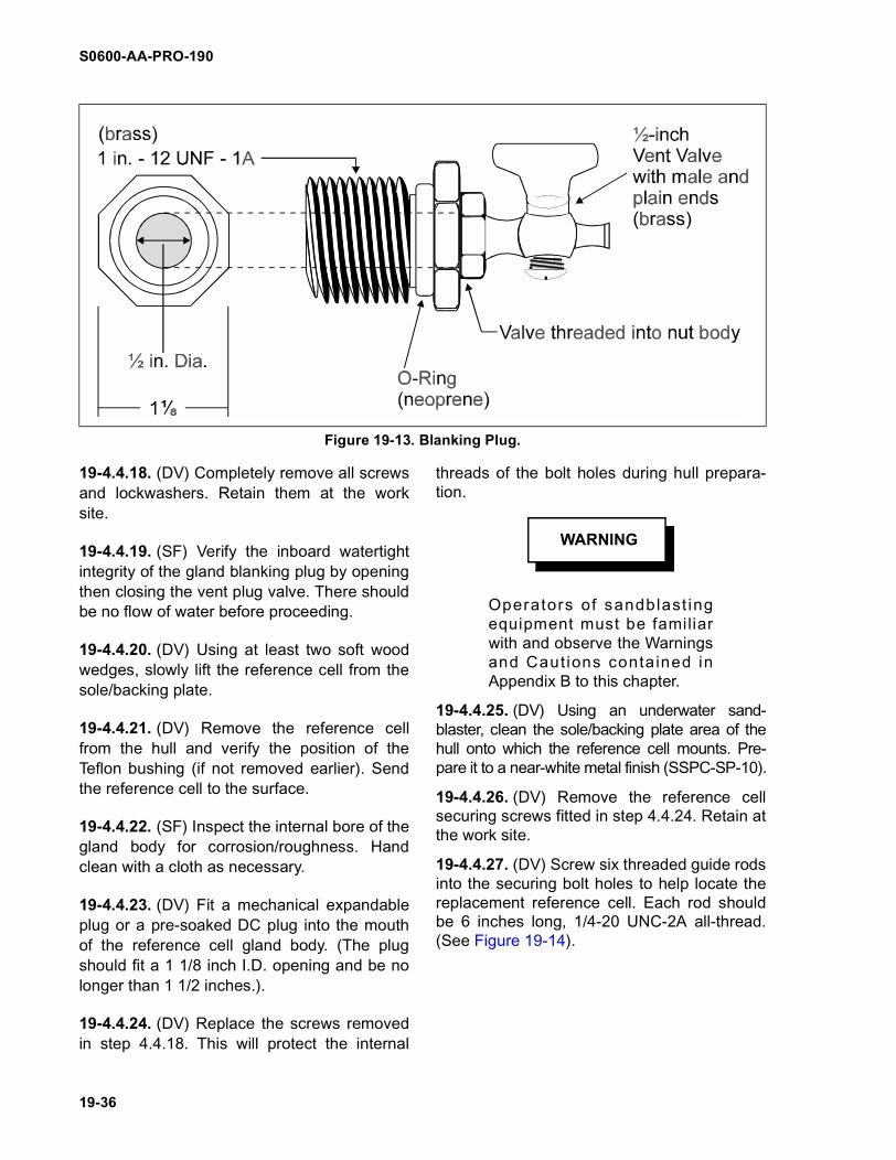
S0600-AA-PRO-190
19-36
19-4.4.18. (DV) Completely remove all screwsand lockwashers. Retain them at the worksite.
19-4.4.19. (SF) Verify the inboard watertightintegrity of the gland blanking plug by openingthen closing the vent plug valve. There shouldbe no flow of water before proceeding.
19-4.4.20. (DV) Using at least two soft woodwedges, slowly lift the reference cell from thesole/backing plate.
19-4.4.21. (DV) Remove the reference cellfrom the hull and verify the position of theTeflon bushing (if not removed earlier). Sendthe reference cell to the surface.
19-4.4.22. (SF) Inspect the internal bore of thegland body for corrosion/roughness. Handclean with a cloth as necessary.
19-4.4.23. (DV) Fit a mechanical expandableplug or a pre-soaked DC plug into the mouthof the reference cell gland body. (The plugshould fit a 1 1/8 inch I.D. opening and be nolonger than 1 1/2 inches.).
19-4.4.24. (DV) Replace the screws removedin step 4.4.18. This will protect the internal
threads of the bolt holes during hull prepara-tion.
Operators of sandblast ingequipment must be familiarwith and observe the Warningsand Cautions contained inAppendix B to this chapter.
19-4.4.25. (DV) Using an underwater sand-blaster, clean the sole/backing plate area of thehull onto which the reference cell mounts. Pre-pare it to a near-white metal finish (SSPC-SP-10).
19-4.4.26. (DV) Remove the reference cellsecuring screws fitted in step 4.4.24. Retain atthe work site.
19-4.4.27. (DV) Screw six threaded guide rodsinto the securing bolt holes to help locate thereplacement reference cell. Each rod shouldbe 6 inches long, 1/4-20 UNC-2A all-thread.(See Figure 19-14).
Figure 19-13. Blanking Plug.
WARNING
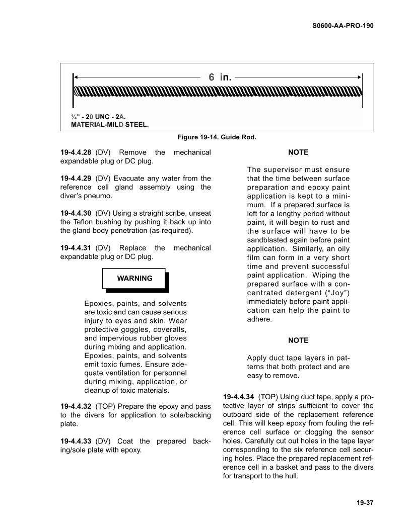
S0600-AA-PRO-190
19-37
19-4.4.28 (DV) Remove the mechanicalexpandable plug or DC plug.
19-4.4.29 (DV) Evacuate any water from thereference cell gland assembly using thediver’s pneumo.
19-4.4.30 (DV) Using a straight scribe, unseatthe Teflon bushing by pushing it back up intothe gland body penetration (as required).
19-4.4.31 (DV) Replace the mechanicalexpandable plug or DC plug.
Epoxies, paints, and solventsare toxic and can cause seriousinjury to eyes and skin. Wearprotective goggles, coveralls,and impervious rubber glovesduring mixing and application.Epoxies, paints, and solventsemit toxic fumes. Ensure ade-quate ventilation for personnelduring mixing, application, orcleanup of toxic materials.
19-4.4.32 (TOP) Prepare the epoxy and passto the divers for application to sole/backingplate.
19-4.4.33 (DV) Coat the prepared back-ing/sole plate with epoxy.
NOTE
The supervisor must ensurethat the time between surfacepreparation and epoxy paintapplication is kept to a mini-mum. If a prepared surface isleft for a lengthy period withoutpaint, it will begin to rust andthe surface wil l have to besandblasted again before paintapplication. Similarly, an oilyfilm can form in a very shorttime and prevent successfulpaint application. Wiping theprepared surface with a con-centrated detergent (“Joy”)immediately before paint appli-cation can help the paint toadhere.
NOTE
Apply duct tape layers in pat-terns that both protect and areeasy to remove.
19-4.4.34 (TOP) Using duct tape, apply a pro-tective layer of strips sufficient to cover theoutboard side of the replacement referencecell. This will keep epoxy from fouling the ref-erence cell surface or clogging the sensorholes. Carefully cut out holes in the tape layercorresponding to the six reference cell secur-ing holes. Place the prepared replacement ref-erence cell in a basket and pass to the diversfor transport to the hull.
Figure 19-14. Guide Rod.
WARNING
S0600-AA-PRO-190
19-38
19-4.4.35 (DV) Remove the mechanicalexpandable plug or DC plug. Heavily apply sil-icone grease to the O-rings of the referencecell and the internal bore of the gland body.
19-4.4.36 (DV) Locate the reference cell overthe six guide rods, and push it into positiononto the hull until it mates with the sole/back-ing plate. If an air lock is experienced in thegland body, release the pressure by ventingthe blanking plug.
19-4.4.37 (DV) Replace each guide rod with asecuring screw and lockwasher, hand tighteneach screw just until it touches the referencecell.
19-4.4.38 (DV) Using the star pattern, torqueeach screw to 10 ft.-lbs.
19-4.4.39 (SF) Slowly remove the glandblanking plug, checking for any signs of waterentry past the reference cell O-rings.
19-4.4.40 (SF) If the Teflon bushing was notremoved in previous steps, use a right-angledscribe to remove it at this time. If the Teflonbushing was not properly pushed in from theoutboard side (paragraph 19-4.4.30), it couldbecome wedged around the reference cellmale probe and be difficult to remove.
19-4.4.41 (SF) Check the electrical voltagecontinuity of the reference cell by measuringthe voltage between the steel hull and the ref-erence cell using a multimeter. If the system isfunctioning correctly, the hull will be negativeand the reference cell will be positive. The DCvoltage should measure approximately 0.6volt DC.
NOTE
If the voltage is zero, it indi-cates either an open wire or ashorted wire or cell. If the volt-age is higher than indicated,the hull is receiving cathodicprotection from some othersource (zincs or electrical leak-
age). On a newly painted steelhull the reading may be as lowas 0.45 volt DC.
19-4.4.42 (DV) Fill the screw holes with epoxyand fair to the reference cell surface. When allepoxy has been applied remove the duct tape.
19-4.4.43 (SF) Clean and grease the internalsurface of the gland body and insert a newTeflon bushing, packing assembly, and cable.
NOTE
When Teflon is compressed itwill creep, i.e. slowly distort andflow away from the compres-sive force. The Teflon packingring is the primary watertightseal. To ensure that the Teflonrings form an effective water-tight seal, it is essential that thegland nut compressing theTeflon is retightened severaltimes.
19-4.4.44 (SF) Insert the gland ring and lock-washer, then screw in the gland nut by hand.Using a torque wrench with an extensionpiece, a crow’s foot and an internal jaw diame-ter of 1 1/8 inch, tighten the gland nut to 25 ft.-lbs. Retighten 6, 12, and 18 hours later.
19-4.4.45 Energize the ICCP system toensure the proper operation of the replace-ment reference cell. Procedures for theinspection and adjustment of system opera-tion following shutdown and for the testing ofreplacement reference cells are provided inNaval Ships’ Technical Manual, Chapter 633,Section 6.
19-4.5 DIELECTRIC SHIELD REPAIRS
Underwater electrical equip-ment must be secured whiledivers are working over the
WARNING

S0600-AA-PRO-190
19-39
side. Hull deterioration is mostsevere while the ICCP systemis de-energized and the effectsare irreversible. The appropri-ate zone of the ship’s ICCPsys tem mus t be secured ,tagged out, and conf irmedsecured before divers maywork on an ICCP dev i ce(anode, dielectric shield, or ref-erence cell). When divers arerequired to work in close prox-imity to an active ICCP anodeand risk of contact with ananode exists, that part of thesystem must be secured for theduration of the repair. In otherthan these situations the ICCPsystem is to remain active.Divers working within 15 feet ofan active system must wear afull dry suit, unisuit, or wet suitwith hood and gloves. Clearcommunications among divers,surface personnel, and inboardShip’s Force personnel are cru-cial for safe and effective coor-dination of tasks.
19-4.5.1 The activity conducting the dielectricshield repair shall:
a. Ensure that all required materials areon hand using Table 19-3 for guidance.
b. Coordinate material, technical, andfunding requirements.
c. Conduct dielectric shield repair trainingin accordance with Naval Ships’ Tech-nical Manual, S9086-VF-STM-010/CH-633, “Cathodic Protection.”
d. Arrange with the ship for control anddisposal of hazardous material.
e. Prepare video and still cameras to doc-ument work throughout the procedure.
f. Notify the ship of any special precau-tions required in the performance of theshield repair.
Table 19-3. Material for Dielectric Shield Repair.
1.Underwater epoxy coating (1 gallon kit per 50 ft2)
2. Liquid immersion heating elements (2)
3. Thermometers, dial (2)
4. Metal buckets (2)
5. Plastic containers, one quart (10 per 50 ft2)
6. Plastic measuring containers, (4 per 50 ft2)
7. Surgical gloves, latex (50 per 50 ft2)
8.Latex gloves, all purpose, oversized (4 pair per day)
9. Coveralls, disposable (5 per day)
10. Oceanclean sandblaster
11. Silica sand (500 lbs per 50 ft2)
12.Air compressor (80-125 psi, 375 cfm with 1-inch hose connection)
13. Bale of rags
14. Bags, plastic, heavy duty, 30 gallon (10)
15. Mixing utensils (wooden sticks) (5 per 50 ft2)
16. Methyl Ethyl Ketone (MEK) (1 gallon per 500 ft2)
17. Abrasive pads, (Scotch-Brite)
18.Liquid detergent, “Joy” brand only (1 pint per 50 ft2)
19.Trowels, plastic, 2 or 3-inch wide (20 per 50 ft2)
20.Paint brush, 3-inch wide, 2-inch bristle length (5 per 50 ft2)
Table 19-3. Material for Dielectric Shield Repair.
S0600-AA-PRO-190
19-40
19-4.5.2 The Ship’s Force shall:
a. Ensure that the ship is moored with theaffected dielectric shield toward the pier.
b. Tag out equipment and systems forconduct of diving operations.
c. Control and dispose of hazardous ma-terials as agreed to with the performing activity.
19-4.5.3 Verify that the appropriate zone ofthe ICCP system has been de-energized andtagged out. The rest of the ICCP systemshould remain energized, ionizing the hull.The energized zone must remain tagged outuntil the epoxy has cured.
Particular care must be exer-cised to protect the anode fromdamage during sandblasting.
19-4.5.4 Prepare the dielectric shield forapplication of the aquatic epoxy paint byremoving all loose and damaged Capastic.Areas of bare metal shall be prepared to asnear-white metal finish (SSPC-SP-10) as pos-sible using an Oceanclean Sandblaster. Usethe sandblaster to fair the edges of soundCapastic to a 20-30 degree angle. For minorrepairs and to repair cracks at theanode/Capastic shield interface, a right-angled grinder may be used.
NOTE
The supervisor must ensurethat the time between surfacepreparation and epoxy paintapplication is kept to a mini-mum. If a prepared surface isleft for a lengthy period withoutpaint, it will begin to rust andthe surface wil l have to besandblasted again before paintapplication. Similarly, an oilyfilm can form in a very shorttime and prevent successful
paint application. Wiping theprepared surface with a con-centrated detergent (e.g. “Joy”)immediately before paint appli-cation can help the paint toadhere.
19-4.5.5 Follow the manufacturer’s instruc-tions for mixing the epoxy paint system.
NOTE
Two-part epoxies general lybegin curing as soon as thecomponents are mixed. Themin imum amount o f pa in trequired should be mixed atany one time.
19-4.5.6 Apply the epoxy paint by hand,trowel, paint brush, or for large areas, by apaint application machine.
NOTE
Painting underwater requirespatience. Divers must avoid thetemptation to try to paint toomuch surface at one time. Toomuch paint applied at one timeoften results in the paint peel-ing away from the preparedsurface before it has time toadhe re . Bes t r esu l ts a reobtained from working the paintinto the prepared sur face,especially in areas of pitting. Inthese areas it is important towork the paint into the surfaceto expel as much water and airas possible.
19-4.5.7 Fair the epoxy up to the edge of theanode and flush with the sound epoxy. Referto paragraph 19-1.4.6.d for required thickness.Do not paint the surface of the anode exceptwhen fairing in the anode securing bolts.
NOTE
Experience with epoxy paintshas shown that application intemperatures lower than 50
CAUTION
S0600-AA-PRO-190
19-41
degrees F is not advisable. Ingeneral, the lower the seawatertemperature, the longer thecure time.
19-4.5.8 Calculate the required cure timeusing the graph in Appendix A.
19-4.5.9 Upon completion of the requiredcure time, visually inspect the epoxy applica-tion. Confirm that the epoxy is cured andappears properly bonded to the existingdielectric shield.
19-4.5.10 When the epoxy cure has beenconfirmed, energize the ICCP system and testin accordance with Naval Ships’ TechnicalManual, Chapter 633, Section 6.
19-4.6 POST-REPAIR PROCEDURES
19-4.6.1 Upon completion of the repair, a writ-ten report should be provided to the ship’sEngineer officer for the ship’s records. Thereport shall contain all information pertainingto the repair including the completed workpackage with all Quality Assurance (QA) doc-uments, documentation of the damage
assessment (NAVSEA Form 4730/7), photo-graphs, any problems encountered togetherwith their solution, and any post repair actionrequired (e.g., periodic inspections, reworkduring next dry docking, etc.). A copy of thereport should be retained by the repairingactivity. A copy of the report should be for-warded to NAVSEA 00C5 when requested.
19-4.6.2 Whenever possible photographicand videotape records of dielectric shieldrepairs should be taken to provide a referencefor the next underwater hull inspection. Copiesof these photographic records along with thehull survey report forms should be forwarded,if requested, to NAVSEA (SEA 00C5).

S0600-AA-PRO-190
19-42
THIS PAGE INTENTIONALLY LEFT BLANK
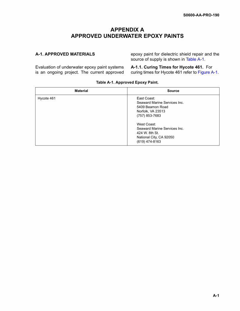
S0600-AA-PRO-190
A-1
A-1. APPROVED MATERIALS
Evaluation of underwater epoxy paint systemsis an ongoing project. The current approved
epoxy paint for dielectric shield repair and thesource of supply is shown in Table A-1.
A-1.1. Curing Times for Hycote 461. Forcuring times for Hycote 461 refer to Figure A-1.
Table A-1. Approved Epoxy Paint.
Material Source
Hycote 461 East Coast:Seaward Marine Services Inc.5409 Beamon RoadNorfolk, VA 23513(757) 853-7683
West Coast:Seaward Marine Services Inc.424 W. 8th St.National City, CA 92050(619) 474-8163
APPENDIX AAPPROVED UNDERWATER EPOXY PAINTS
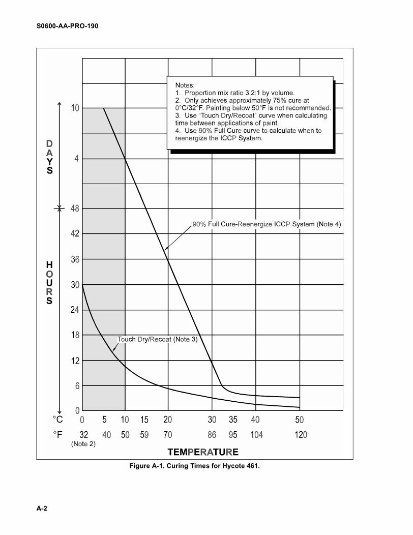
S0600-AA-PRO-190
A-2
Figure A-1. Curing Times for Hycote 461.
S0600-AA-PRO-190
B-1
B-1 SETUP
Improper use o f the sand-blaster can be extremely haz-ardous.
Always depressurize the blasttank whenever the unit is leftunattended.
NOTE
Figure B-1 provides informationconcerning the correct methodof connecting the hoses for thesandblaster.
B-1.1 Place blast tank on a solid surface nearthe work site.
B-1.2 Inspect the blast tank and componentsfor damage and missing parts. Repair orreplace as necessary. Ensure that there is nogrease on the O-rings and gaskets.
B-1.3 Check ancillary equipment against theinventory list.
B-1.4 Check blast hose end fittings to ensurethat the gaskets are in place.
B-1.5 Connect the blast hose with quick dis-connect couplings to the outlet of the blastregulator:
a. Push the coupling faces firmly togetherand rotate in a clockwise direction untilthe locking lugs are engaged.
b. With the 1/8-inch drilled holes in thecouplings aligned, insert the safety clip.
B-1.6 Connect additional lengths of blasthose following steps a. and b. above until therequired length is obtained. This shouldinclude the final length with a threaded hosefitting for the blast nozzle.
B-1.7 Install the blast nozzle:
a. Coat the nozzle threads with anti-seizecompound. Do not use grease.
Do not overtighten the blastnozzle when installing it on thehose end threaded fitting. Donot use a wrench to tighten.
b. Install the blast nozzle with a gasket.Tighten to contact then add 1/4 turnhand tight.
B-1.8 Connect the remote control system withthe deadman switch:
a. Connect the required lengths of exten-sion section twin control hose (each 50feet long) to the starting section hosesconnected to the air inlet piping and theair inlet control valve.
b. Connect the required lengths of exten-sion section control hose (each 50 feetlong) to the starting section hose con-nected to the abrasive regulator.
c. Connect the deadman control switchwith hoses to the proper color-codedextension hoses.
d. Ensure that all hose fittings are tight.
WARNING
WARNING
CAUTION
APPENDIX BSETUP AND OPERATION OF THE SANDBLASTER

S0600-AA-PRO-190
B-2
e. Ensure that the petcock on the dead-man control switch is shut.
For safe operation the dead-man control switch should belocated not more than 6 inchesfrom the blast nozzle coupling.
B-1.9 Using tie-wraps, attach the deadmancontrol switch to the blast hose at a comfort-able point near the nozzle, but not more than 6inches from the blast nozzle coupling.
B-1.10 Using tie-wraps, attach the twin con-trol hoses and abrasive regulator control hoseto the blast hose. Strap loosely to prevent thecontrol hoses from being crushed when theblast hose is turned.
Figure B-1. Hose Connections for the Sandblaster
WARNING

S0600-AA-PRO-190
B-3
To prevent the operator fromreceiving static electricity gen-erated by the abrasive flow, theblast tank must be grounded.
B-1.11 Connect the grounding cable to theunit grounding connection and to a knownground point.
B-1.12 Shut the manual exhaust valve.
B-1.13 Shut the manual air inlet valve.
B-1.14 Open the choke valve located in thevertical air line piping on the blast tank. (Thechoke valve handle is in line with the pipingwhen the valve is open).
B-1.15 Set the abrasive regulator by turningthe handle three to four turns counterclock-wise from the fully shut position. Do not turnmore than five turns.
B-1.16 Connect the air supply to the air inletconnection. Install the safety clip, if applicable.
Topside personnel must wearear and eye protection whenoperating the sandblaster.
Do not exceed 120 psi inlet airpressure.
B-1.17 Pressurize up to the manual air inletvalve and the deadman switch with 85-120 psilow pressure air.
B-1.18 Inspect all fittings for leaks. Repair allleaks before proceeding.
B-1.19 Test operate the deadman controlswitch:
a. Activate the switch by pressing thesafety button into the side of the switch.
b. Depress the switch operating handle.Pressurized air should discharge fromthe nozzle.
c. Check the air inlet valve next to theabrasive regulator for proper operationand for leaks.
d. Release the switch operating handle.Pressurized air flow should stop.
To prevent serious personnelinjury, exercise extreme cau-tion when working around thesandblaster when the tank ispressurized.
B-1.20 Pressurize the blast tank:
a. Open the manual air inlet valve.
To prevent serious personneli n ju r y, check the sea l i ngplunger and sealing O-ringfrom a safe distance.
b. Check to ensure that the sealingplunger has moved upward and isseated against the sealing O-ring.
WARNING
WARNING
WARNING
WARNING
WARNING
S0600-AA-PRO-190
B-4
c. Check for leaks. Repair all leaks beforeproceeding.
To prevent serious personnelinjury and equipment damage,do not point the blast nozzle atpersonnel or equipment.
The carbide nozzle is very frag-ile and shatters easily. Do notdrop or mishandle it.
B-1.21 Hold the blast hose securely at thenozzle end and point it away from personneland equipment.
B-1.22 Fully open the petcock on the dead-man control switch.
B-1.23 Press the safety button and depressthe operating handle to activate the deadmancontrol switch. Pressurized air will be dis-charged from the blast nozzle.
B-1.24 Check the operation of the abrasiveregulator:
a. Open the toggle valve to start air flowfrom the abrasive regulator and tank.
b. Stop the pressurized air flow from theabrasive regulator and tank by shuttingthe toggle valve.
c. Release the operating handle of thedeadman control switch.
B-1.25 Fill the blast tank with abrasive:
a. Depressurize the blast tank.
(1) Shut the manual air inlet valve.
(2) Press the safety button, depressthe operating handle to activatethe deadman control switch, andopen the toggle valve to removeexcess air from the blast tank andreduce noise.
(3) Slowly open the manual exhaustvalve.
(4) Shut the toggle valve and releasethe operating handle of the dead-man control switch when the blasttank is depressurized.
(5) Verify that the sealing plungerhas moved downward on the sup-port pipe.
To prevent accelerated wearon the plunger face and O-ring,do not overfill the blast tankwith abrasive. The recom-mended level is no higher thanthe bottom edge of the sealingplunger.
NOTE
The recommended abrasivematerial is Silica Sand #2.
b. Fill the blast tank with abrasive.
To prevent serious personnelinjury, exercise extreme cau-tion when working around thesandblaster when the tank ispressurized.
WARNING
CAUTION
CAUTION
WARNING
S0600-AA-PRO-190
B-5
The topside operator mustwear ear and eye protectionwhen opera t ing the sand-blaster.
c. Pressurize the blast tank:
(1) Shut the manual exhaust valve.
(2) Slowly open the manual air inletvalve.
To prevent serious personnelin ju r y, check the sea l i ngplunger and sealing O-ringfrom a safe distance.
d. Check to ensure that the sealingplunger has moved upward against thesealing O-ring.
B-1.26 The sandblaster is now fully operational.
B-2 OPERATION
Wearing a Mark 21 helmet, themaximum allowable time for adiver to operate the sand-blaster is 5 hours.
To prevent serious personnelinjury, exercise extreme cau-tion when working around thesandblaster when the tank ispressurized.
Improper use of the sand-blaster can be extremely haz-ardous.
To prevent the operator fromreceiving static electricity gen-erated by abrasive flow, ensurethat the blast tank is properlygrounded.
Do not exceed 120 psi inlet airpressure.
Topside personnel must wearear and eye protection whenoperating the sandblaster.
Always depressurize the blasttank whenever the unit is to beleft unattended.
B-2.1 Before the diver enters the water,ensure that the following steps have beenaccomplished:
a. All steps in B-1, with special attentionbeing given to the following:
(1) The blast tank has been pressur-ized with the sealing plungeragainst the sealing O-ring.
WARNING
WARNING
WARNING
WARNING
WARNING
WARNING
WARNING
WARNING
WARNING
S0600-AA-PRO-190
B-6
(2) The safety button on the dead-man control switch has beenpulled out to prevent activation.
(3) The petcock on the deadmancontrol switch has been shut.
(4) The toggle handle on the dead-man control switch has been shut(handle is pointed toward thehose).
(5) The abrasive regulator has beenadjusted by turning three to fourturns counterclockwise from thefully shut position. No more thanfive turns have been used.
b. Any discrepancies noted have beencorrected.
c. Additional bags/containers of abrasiveare available for refilling the blast tank.
To prevent serious personnelinjury and equipment damage,do not point the blast nozzle atpersonnel or equipment.
The carbide nozzle is very frag-ile and shatters easily. Do notdrop or mishandle it.
B-2.2 Hold the blast hose securely at the noz-zle end and point it away from personnel andequipment.
B-2.3 Fully open the petcock on the deadmanswitch.
B-2.4 Press the safety button and depressthe operating handle to activate the deadmancontrol switch. Pressurized air will be dis-charged from the blast nozzle.
NOTE
The diver controls the startingand stopping of abrasive flowfrom the blast nozzle by open-ing and shutting the togglevalve. The amount of abrasivedischarged is manually con-trolled by turning the crank han-dle on the abrasive regulator;clockwise to decrease flow,counterclockwise to increaseflow.
NOTE
For efficient blasting, air mustbe supplied for 30 secondsbefore the togg le valve isopened to supply sand.
B-2.5 With the operating handle depressed,start the flow of abrasive by opening the togglevalve (handle is pointed away from the hose).
NOTE
Practice in the use of the sand-blaster is required in order toclean only the pre-determinedarea. Overly long bursts ofsandblasting can obscure thework area and lead to the diverwandering from the pre-deter-mined area thus creating addi-tional work and increasing therisk of damage to anodes andrference cells. Overly shortduration bursts will reduce theability to obtain proper sandvelocity which will reduce the
WARNING
CAUTION
S0600-AA-PRO-190
B-7
effectivness of the sandblast-ing.
NOTE
Even though abrasive flow willbe stopped when the togglevalve is shut, pressurized airwill continue to be dischargedfrom the nozzle as long as theoperating handle is depressed.
B-2.6 Stop the flow of abrasive by shuttingthe toggle valve.
B-2.7 Release the operating handle of thedeadman control switch to stop air flow fromthe nozzle.
B-2.8 Restart blasting by following stepsB-2.2 through B-2.5.
B-2.9 Refill the blast tank with abrasive:
a. Release the operating handle of thedeadman control switch to stop blast-ing. Do not shut the toggle valve.
b. Depressurize the blast tank:
(1) Shut the manual air inlet valve.
(2) Press the safety button anddepress the operating handle toactivate the deadman controlswitch to remove excess air fromthe blast tank and reduce topsidenoise.
(3) Slowly open the manual exhaustvalve.
(4) Shut the toggle valve and releasethe operating handle of the dead-man control switch when the blasttank is depressurized.
(5) Verify that the sealing plungerhas moved downward on the sup-port pipe.
To prevent accelerated wearon the sealing plunger face andO-ring, do not overfill the blasttank with abrasive. The recom-mended level is no higher thanthe bottom edge of the sealingplunger.
c. Fill the blast tank with abrasive mate-rial.
d. Pressurize the blast tank:
(1) Shut the manual exhaust valve.
(2) Slowly open the manual air inletvalve.
(3) Verify that the sealing plungermoves upward against the seal-ing O-ring.
B-2.10 Restart blasting in accordance withsteps B-2.2 through B-2.5.
B-2.11 Secure from blasting:
a. Shut the toggle valve.
To prevent the hose frombecoming clogged with abra-sive, do not release the operat-ing handle on the deadmanswitch until all abrasive hasbeen discharged from the noz-zle.
b. Release the operating handle. Ensurethat the safety button is pulled out toprevent depressing the handle. Shutthe petcock.
CAUTION
CAUTION
S0600-AA-PRO-190
B-8
c. Pull the blast hose to the surface.
B-2.12. Blow out water and abrasive residuefrom the blast hose:
a. Lay out the blast hose with as fewbends as possible.
b. Hold the blast hose and nozzlesecurely at the nozzle end and pointedaway from personnel and equipment.
c. Check to ensure that the petcock andtoggle valve are shut.
d. Press the safety button and depressthe operating handle to activate thedeadman control switch. Pressurizedair will be discharged from the nozzlealong with any water and abrasive res-idue.
e. Release the handle of the deadmancontrol switch when all water and abra-sive residue have been dischargedfrom the nozzle.
B-2.13 Depressurize the blast tank in accor-dance with step B-2.9b.
Never shut off the main air sup-ply to the blast tank until the tankis completely depressurized.
To prevent serious personnelinjury, ensure that the main airsupply valve is shut and the airsupply hose is depressurizedbefore disconnecting.
B-2.14. Shut the main air supply valve to theblast tank.
B-2.15. Disconnect the depressurized air sup-ply hose from the air inlet line if blasting hasbeen completed.
B-2.16. Perform post-dive maintenance inaccordance with MRC UW2160 R-1.
NOTE
Setup and operating proce-dures as well as maintenanceprocedures for the sandblasterwill be provided with the equip-ment. Operators must adhereto these procedures to ensureproper operation and mainte-nance of the equipment.
WARNING
WARNING