Embed Size (px)
Citation preview
Prosthetic Technique Manual
SimplicityScience Value
i n t e r n a l
2
3-6
789
10
11-1213-1516-1718-2122-2526-2728-3132-3536-38
39-40
424854606470747886
I. Introduction
II. Treatment Planning
III. Restorative OptionsImplant-level Cement-retained RestorationsImplant-level Screw-retained RestorationsAbutment-level Screw-retained Restorations Ball Abutment Overdenture
IV. Impression TechniquesOverviewEmergence Profile ChartsPrepared Abutment Impression, Closed Tray - Crown and Bridge TechniqueImplant-level Impression, Closed Tray - Indirect Transfer TechniqueAbutment-level Impression, Closed Tray - Indirect Transfer TechniqueCustom Tray FabricationImplant-level Impression, Open Tray - Direct Pick-up TechniqueAbutment-level Impression, Open Tray - Direct Pick-up TechniqueBall Abutment Impression, Closed Tray - Indirect Transfer Technique
V. Abutment Selection Flow Chart
VI. Restorative OptionsSingle or Multiple-unit Cement-retained - Chairside Abutment ModificationSingle-tooth Screw-retained - Custom Cast AbutmentSingle-tooth Cement-retained - Laboratory Prepared AbutmentMultiple-unit Screw-retained - Custom Cast AbutmentsMultiple-unit Cement-retained - Laboratory Prepared AbutmentsBall Abutment Overdenture, Existing Denture, Chairside Pick-upBall Abutment Overdenture, New DentureBar Overdenture - Screw-retained Implant or Abutment-level, Cast BarBar Overdenture - Screw-retained Implant-level, Laser Welded Bar
1 - 8 8 8 - 2 4 6 - 8 3 3 8
�
T A B L E O F C O N T E N T S

BioHorizons Internal implant system is designed for complete surgical and prosthetic versatility. The implants have a clinically proven, biomechanical thread design combined with a secure internal hex connection. They provide the flexibility of either traditional two-stage, single-stage or immediate load treatment plans.
Each implant comes pre-mounted with a free, gold-hued esthetic 3inOne™ Abutment. This multi-purpose abutment may be used: • at placement for immediate load restorations • as an impression coping when coupled with a Ball-top Screw • as a final/temporary abutment for a cemented restoration
The beveled restorative platform provides an excellent biomechanical seal at the implant/abutment interface and aids in distributing lateral load away from the Abutment Screw. These features, combined with the use of Spiralock® screw technology, virtually eliminate unwanted screw loosening.
Features and Benefits of the BioHorizons Internal System
Value and Simplicity • Free esthetic abutment pre-mounted on every implant
Evidence-based Design • Clinically proven thread form for improved bone-to-implant contact and bone response.
Strength • Ti-6Al-4V - Titanium alloy, the strongest used in implant dentistry
Choice of Two Proven Surface Treatments • Resorbable Blast Texturing (RBT) • Hydroxylapatite (HA)
4 Implant Diameters / 3 Prosthetic Platform Diameters • Ø3.5mm body / Ø3.5mm platform • Ø4.0mm body / Ø4.5mm platform • Ø5.0mm body / Ø5.7mm platform • Ø6.0mm body / Ø5.7mm platform
Implant Lengths • 9mm • 10.5mm • �2mm • 15mm
2
I N T R O D U C T I O N
1 - 8 8 8 - 2 4 6 - 8 3 3 8
�
Treatment Planning
T R E A T M E N T P L A N N I N G
For ideal results in implant dentistry, the treatment team should be in agreement and in communication throughout all stages of therapy. The patient, the restorative and surgical doctors, as well as the dental laboratory should understand and agree upon the treatment plan. The treatment plan is responsible for the design, number and position of the implants.
Diagnostic CastsMounted study casts and a diagnostic wax-up are the foundation for determining implant location. Surgical Guide TemplatesOnce the diagnostic wax-up is finalized, the restorative doctor or dental laboratory fabricates the surgical guide template. This guide dictates to the surgeon the implant location that offers the best support for the prosthesis, as well as optimal esthetics and hygiene requirements. The surgical guide also provides information about the tooth and supporting structures that have been lost.
Laboratory Guide TemplatesA matrix of the diagnostic wax-up may also be utilized by the laboratory when developing the final prosthesis. The matrix acts as a guide for position and contour of the prosthesis.
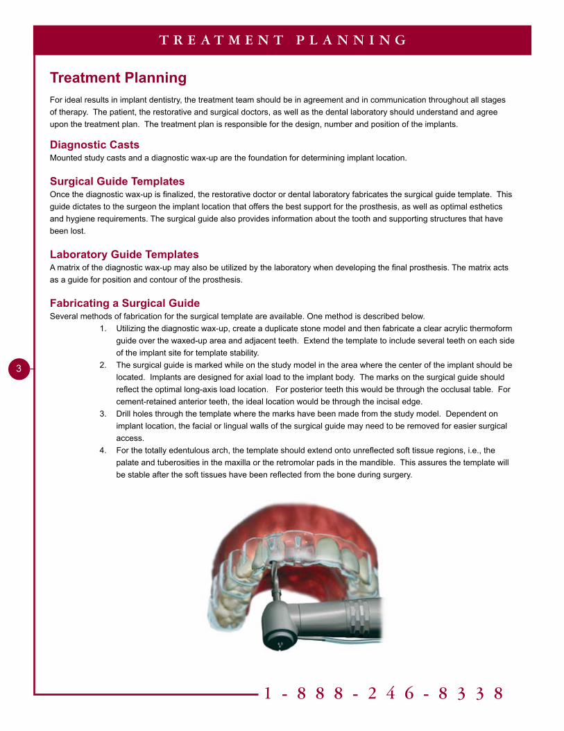
Fabricating a Surgical GuideSeveral methods of fabrication for the surgical template are available. One method is described below.
1. Utilizing the diagnostic wax-up, create a duplicate stone model and then fabricate a clear acrylic thermoform guide over the waxed-up area and adjacent teeth. Extend the template to include several teeth on each side of the implant site for template stability.
2. The surgical guide is marked while on the study model in the area where the center of the implant should be located. Implants are designed for axial load to the implant body. The marks on the surgical guide should reflect the optimal long-axis load location. For posterior teeth this would be through the occlusal table. For cement-retained anterior teeth, the ideal location would be through the incisal edge.
3. Drill holes through the template where the marks have been made from the study model. Dependent on implant location, the facial or lingual walls of the surgical guide may need to be removed for easier surgical access.
4. For the totally edentulous arch, the template should extend onto unreflected soft tissue regions, i.e., the palate and tuberosities in the maxilla or the retromolar pads in the mandible. This assures the template will be stable after the soft tissues have been reflected from the bone during surgery.
�
Surgical Options
T R E A T M E N T P L A N N I N G
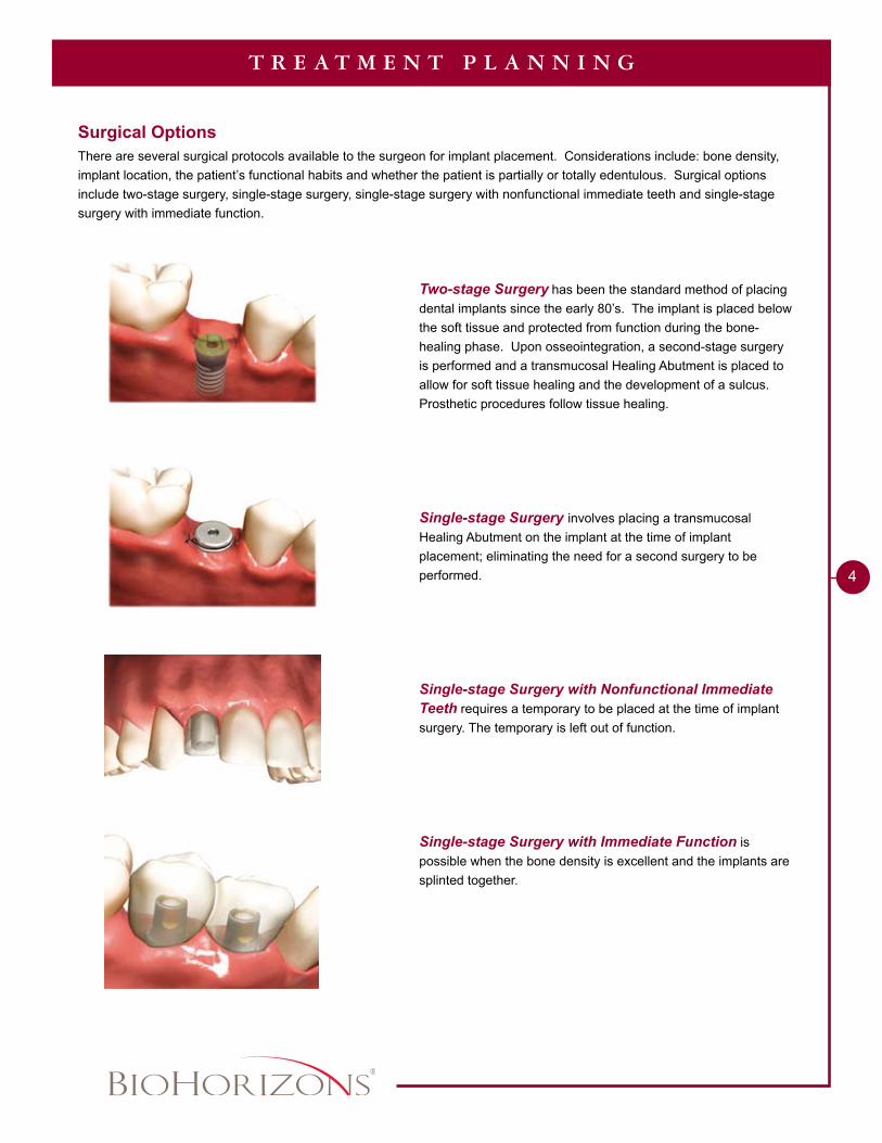
There are several surgical protocols available to the surgeon for implant placement. Considerations include: bone density, implant location, the patient’s functional habits and whether the patient is partially or totally edentulous. Surgical options include two-stage surgery, single-stage surgery, single-stage surgery with nonfunctional immediate teeth and single-stage surgery with immediate function.
Two-stage Surgery has been the standard method of placing dental implants since the early 80’s. The implant is placed below the soft tissue and protected from function during the bone-healing phase. Upon osseointegration, a second-stage surgery is performed and a transmucosal Healing Abutment is placed to allow for soft tissue healing and the development of a sulcus. Prosthetic procedures follow tissue healing.
Single-stage Surgery involves placing a transmucosal Healing Abutment on the implant at the time of implant placement; eliminating the need for a second surgery to be performed.
Single-stage Surgery with Nonfunctional Immediate Teeth requires a temporary to be placed at the time of implant surgery. The temporary is left out of function.
Single-stage Surgery with Immediate Function is possible when the bone density is excellent and the implants are splinted together.
1 - 8 8 8 - 2 4 6 - 8 3 3 8
5
T R E A T M E N T P L A N N I N G
Temporary ProsthesisTemporary restorations are dependent on the treatment plan, the requirements of the patient and the final restoration planned.
Temporization Prior to Second-stage Surgery Totally edentulous patient1. The existing denture is relieved over the implant sites and relined with a soft material.2. Transitional implants may be placed in between the permanent implants. A provisional restoration can be fabricated
or the existing denture may be modified to be supported by the transitional implants. Partially edentulous patient1. A removable appliance can be made which is relieved to protect the implant from function.2. A “Maryland bridge” can be fabricated.3. In non-esthetic zones a temporary may not be necessary.
Temporization After Second-stage SurgeryCement-retained crown & bridge1. A temporary crown or bridge can be fabricated utilizing the free 3inOne Abutment that comes with the implant.
Techniques used for traditional temporaries on natural teeth are used.Screw-retained crown & bridge1. For single-unit screw-retained temporaries the free 3inOne Abutment would also be used.
OcclusionThe occlusal philosophy for dental implants is highly variable and dependent upon several parameters. Implant and natural tooth position, number, size and prosthesis design produce a myriad of possible combinations. The restoring dentist has the responsibility to minimize overload to the bone-to-implant interface.
For partially edentulous patients, occlusal forces between implants and teeth should be harmonized. A heavy bite-force occlusal adjustment is used to depress the natural teeth, positioning them closer to the implant position and equally sharing the load. Every effort should be made to direct the occlusal forces down the long axis of the implant.
For totally edentulous patients with fixed restorations, balanced centric occlusion with anterior guidance and posterior disclusion in all excursions, is suggested. Every effort should be made to direct the occlusal forces down the long axis of the implant.
A totally edentulous patient with a complete removable prosthesis should have bilateral balanced occlusion.
Patients with parafunctional habits should be provided with occlusal night guards, which will minimize destructive forces.
MaintenanceOngoing hygiene for the implant patient is vital. Three-month hygiene recall is suggested. Instruments designed for implant scaling, such as Implacare® instruments from Hu-Friedy® should be utilized. The stainless steel handles may be fitted with assorted tip designs used for hygiene on natural teeth. The Implacare® scalers will not damage implant abutments and contain no glass or graphite fillers that can scratch titanium implant abutments.
�
T R E A T M E N T P L A N N I N G
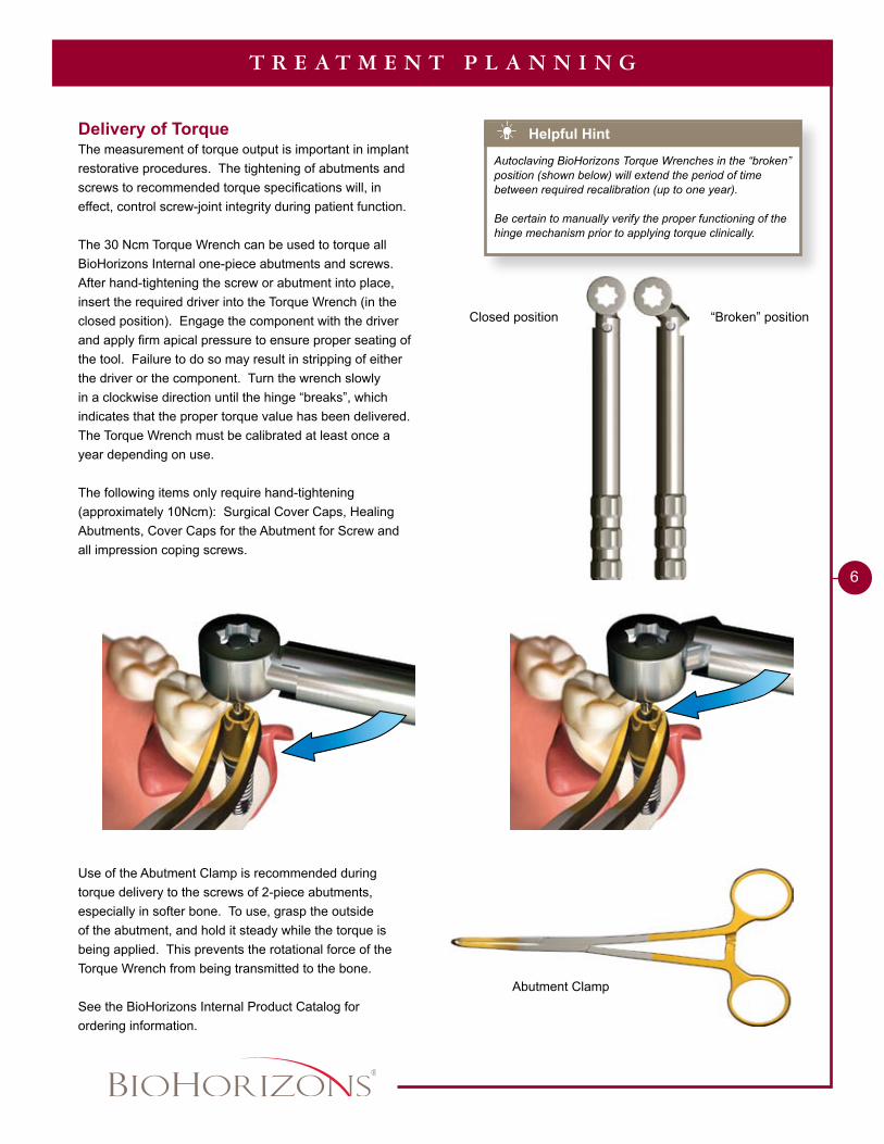
“Broken” positionClosed position
Helpful Hint
Autoclaving BioHorizons Torque Wrenches in the “broken” position (shown below) will extend the period of time between required recalibration (up to one year).
Be certain to manually verify the proper functioning of the hinge mechanism prior to applying torque clinically.
Delivery of Torque The measurement of torque output is important in implant restorative procedures. The tightening of abutments and screws to recommended torque specifications will, in effect, control screw-joint integrity during patient function.
The 30 Ncm Torque Wrench can be used to torque all BioHorizons Internal one-piece abutments and screws. After hand-tightening the screw or abutment into place, insert the required driver into the Torque Wrench (in the closed position). Engage the component with the driver and apply firm apical pressure to ensure proper seating of the tool. Failure to do so may result in stripping of either the driver or the component. Turn the wrench slowly in a clockwise direction until the hinge “breaks”, which indicates that the proper torque value has been delivered. The Torque Wrench must be calibrated at least once a year depending on use.
The following items only require hand-tightening (approximately 10Ncm): Surgical Cover Caps, Healing Abutments, Cover Caps for the Abutment for Screw and all impression coping screws.
Use of the Abutment Clamp is recommended during torque delivery to the screws of 2-piece abutments, especially in softer bone. To use, grasp the outside of the abutment, and hold it steady while the torque is being applied. This prevents the rotational force of the Torque Wrench from being transmitted to the bone.
See the BioHorizons Internal Product Catalog for ordering information.
Abutment Clamp
1 - 8 8 8 - 2 4 6 - 8 3 3 8
7
Cement-retained Restorations
R E S T O R A T I V E O P T I O N S
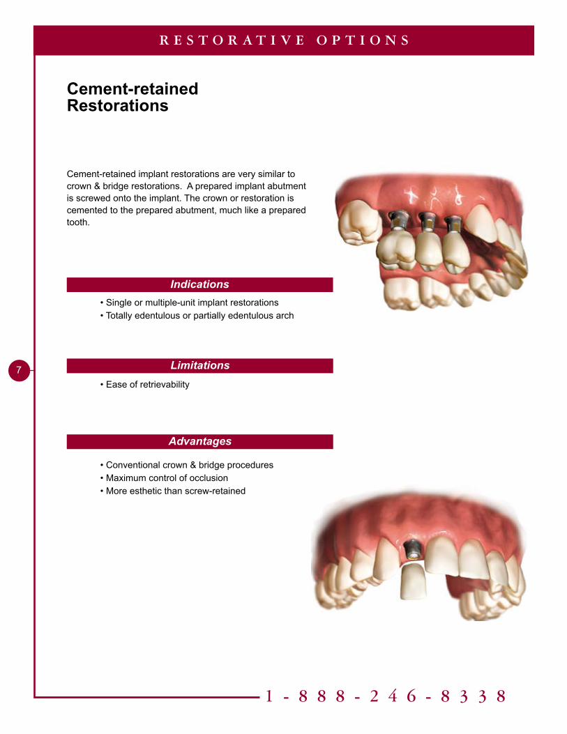
Cement-retained implant restorations are very similar to crown & bridge restorations. A prepared implant abutment is screwed onto the implant. The crown or restoration is cemented to the prepared abutment, much like a prepared tooth.
Indications
Limitations
Advantages
• Single or multiple-unit implant restorations • Totally edentulous or partially edentulous arch
• Ease of retrievability
• Conventional crown & bridge procedures • Maximum control of occlusion • More esthetic than screw-retained
8
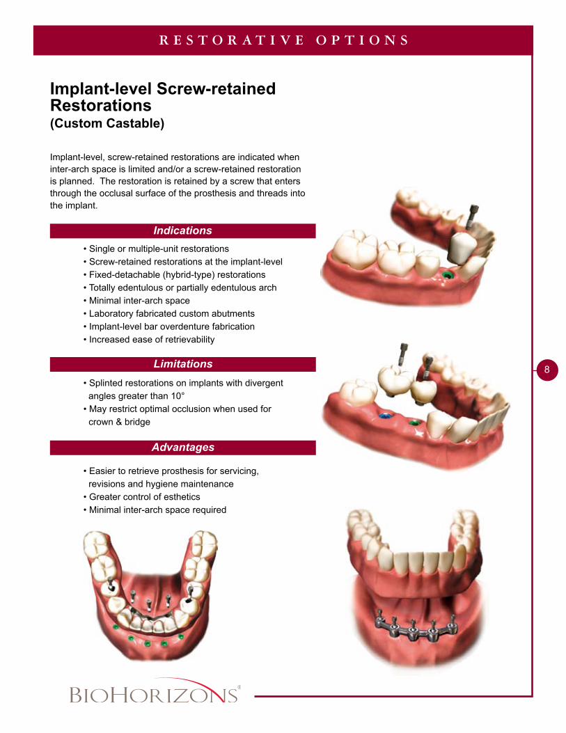
Implant-level Screw-retained Restorations(Custom Castable)
R E S T O R A T I V E O P T I O N S
Indications
Limitations
Advantages
Implant-level, screw-retained restorations are indicated when inter-arch space is limited and/or a screw-retained restoration is planned. The restoration is retained by a screw that enters through the occlusal surface of the prosthesis and threads into the implant.
• Single or multiple-unit restorations • Screw-retained restorations at the implant-level • Fixed-detachable (hybrid-type) restorations • Totally edentulous or partially edentulous arch • Minimal inter-arch space • Laboratory fabricated custom abutments • Implant-level bar overdenture fabrication • Increased ease of retrievability
• Splinted restorations on implants with divergent angles greater than 10° • May restrict optimal occlusion when used for crown & bridge
• Easier to retrieve prosthesis for servicing, revisions and hygiene maintenance • Greater control of esthetics • Minimal inter-arch space required
1 - 8 8 8 - 2 4 6 - 8 3 3 8
9
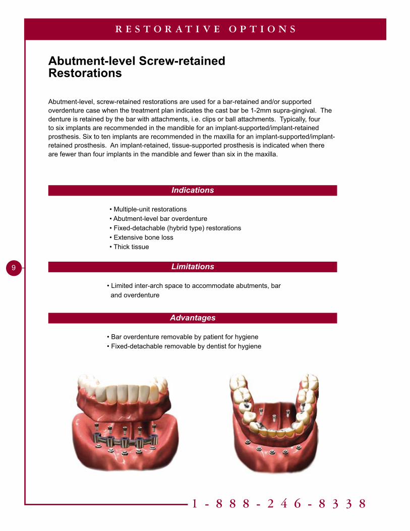
Abutment-level Screw-retainedRestorations
R E S T O R A T I V E O P T I O N S
Indications
Limitations
Advantages
• Bar overdenture removable by patient for hygiene• Fixed-detachable removable by dentist for hygiene
• Limited inter-arch space to accommodate abutments, bar and overdenture
• Multiple-unit restorations• Abutment-level bar overdenture• Fixed-detachable (hybrid type) restorations• Extensive bone loss• Thick tissue
Abutment-level, screw-retained restorations are used for a bar-retained and/or supported overdenture case when the treatment plan indicates the cast bar be 1-2mm supra-gingival. The denture is retained by the bar with attachments, i.e. clips or ball attachments. Typically, four to six implants are recommended in the mandible for an implant-supported/implant-retained prosthesis. Six to ten implants are recommended in the maxilla for an implant-supported/implant-retained prosthesis. An implant-retained, tissue-supported prosthesis is indicated when there are fewer than four implants in the mandible and fewer than six in the maxilla.
10
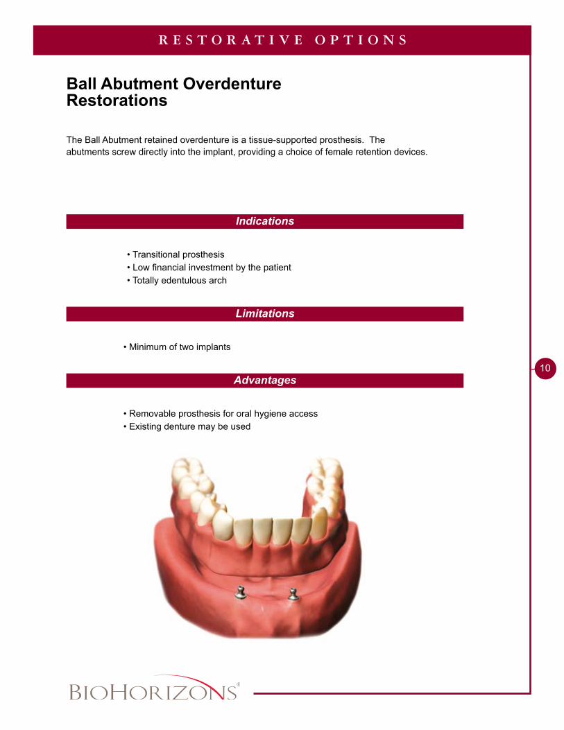
The Ball Abutment retained overdenture is a tissue-supported prosthesis. The abutments screw directly into the implant, providing a choice of female retention devices.
R E S T O R A T I V E O P T I O N S
Indications
Limitations
Advantages
• Removable prosthesis for oral hygiene access• Existing denture may be used
• Minimum of two implants
• Transitional prosthesis• Low financial investment by the patient• Totally edentulous arch
Ball Abutment OverdentureRestorations
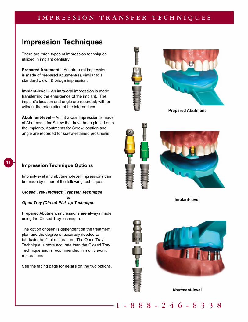
Prepared Abutment
Implant-level
Abutment-level
1 - 8 8 8 - 2 4 6 - 8 3 3 8
��
Impression TechniquesThere are three types of impression techniques utilized in implant dentistry:
Prepared Abutment – An intra-oral impression is made of prepared abutment(s), similar to a standard crown & bridge impression.
Implant-level – An intra-oral impression is made transferring the emergence of the implant. The implant’s location and angle are recorded; with or without the orientation of the internal hex.
Abutment-level – An intra-oral impression is made of Abutments for Screw that have been placed onto the implants. Abutments for Screw location and angle are recorded for screw-retained prosthesis.
Impression Technique Options
Implant-level and abutment-level impressions can be made by either of the following techniques:
Closed Tray (Indirect) Transfer Techniqueor
Open Tray (Direct) Pick-up Technique
Prepared Abutment impressions are always made using the Closed Tray technique.
The option chosen is dependent on the treatment plan and the degree of accuracy needed to fabricate the final restoration. The Open Tray Technique is more accurate than the Closed Tray Technique and is recommended in multiple-unit restorations.
See the facing page for details on the two options.
I M P R E S S I O N T R A N S F E R T E C H N I Q U E S
P
P
P
ABTP
Closed Tray – Indirect Transfer Technique
Open Tray – Direct Pick-up Technique
�2
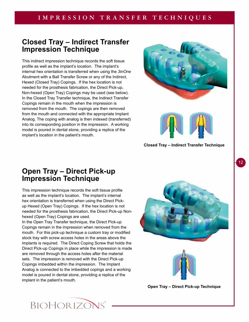
Closed Tray – Indirect Transfer Impression Technique
This indirect impression technique records the soft tissue profile as well as the implant’s location. The implant’s internal hex orientation is transferred when using the 3inOne Abutment with a Ball Transfer Screw or any of the Indirect, Hexed (Closed Tray) Copings. If the hex location is not needed for the prosthesis fabrication, the Direct Pick-up, Non-hexed (Open Tray) Copings may be used (see below).In the Closed Tray Transfer technique, the Indirect Transfer Copings remain in the mouth when the impression is removed from the mouth. The copings are then removed from the mouth and connected with the appropriate Implant Analog. The coping with analog is then indexed (transferred) into its corresponding position in the impression. A working model is poured in dental stone, providing a replica of the implant’s location in the patient’s mouth.
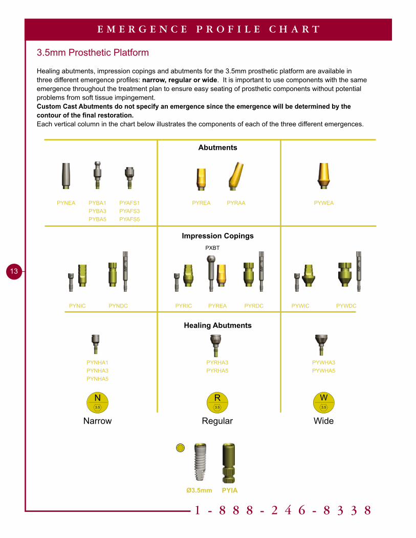
Open Tray – Direct Pick-up Impression Technique This impression technique records the soft tissue profile as well as the implant’s location. The implant’s internal hex orientation is transferred when using the Direct Pick-up Hexed (Open Tray) Copings. If the hex location is not needed for the prosthesis fabrication, the Direct Pick-up Non-hexed (Open Tray) Copings are used.In the Open Tray Transfer technique, the Direct Pick-up Copings remain in the impression when removed from the mouth. For this pick-up technique a custom tray or modified stock tray with screw access holes in the areas above the implants is required. The Direct Coping Screw that holds the Direct Pick-up Copings in place while the impression is made are removed through the access holes after the material sets. The impression is removed with the Direct Pick-up Copings imbedded within the impression. The Implant Analog is connected to the imbedded copings and a working model is poured in dental stone, providing a replica of the implant in the patient’s mouth.
I M P R E S S I O N T R A N S F E R T E C H N I Q U E S
Abutments
Impression Copings
Healing Abutments
1 - 8 8 8 - 2 4 6 - 8 3 3 8
��
E M E R G E N C E P R O F I L E C H A R T
PYNHA�PYNHA�PYNHA5
N3.5
R3.5
W3.5
PYWHA3PYWHA5
PYRHA�PYRHA5
P
IMP
PIM
PP
IMP
PYRDC PYWIC
PYNEA PYAFS�PYAFS�PYAFS5
P PP
PYBA�PYBA�PYBA5
Narrow
PXBT
P
PYWEA
PYRICPYNIC PYNDC PYWDC
PYREA PYRAA
PYREA
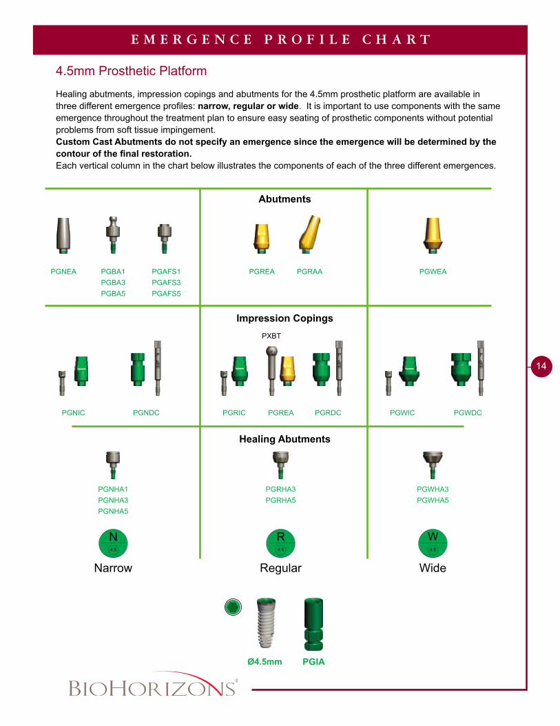
3.5mm Prosthetic Platform
Healing abutments, impression copings and abutments for the 3.5mm prosthetic platform are available in three different emergence profiles: narrow, regular or wide. It is important to use components with the same emergence throughout the treatment plan to ensure easy seating of prosthetic components without potential problems from soft tissue impingement.Custom Cast Abutments do not specify an emergence since the emergence will be determined by the contour of the final restoration.Each vertical column in the chart below illustrates the components of each of the three different emergences.
Regular Wide
Ø3.5mm PYIA
Abutments
Impression Copings
Healing Abutments
��
E M E R G E N C E P R O F I L E C H A R T
PGBA�PGBA�PGBA5
PGNHA�PGNHA�PGNHA5
PGWHA3PGWHA5
PGRHA�PGRHA5
PGNDC
W4.5
R4.5
N4.5
P P
P
IMP
P
IMP
P
IMP
P
P
PGWIC
PGNEA PGAFS�PGAFS�PGAFS5
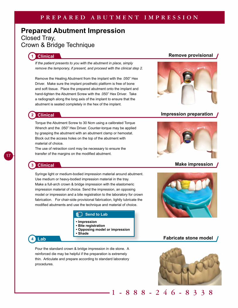
4.5mm Prosthetic Platform
Healing abutments, impression copings and abutments for the 4.5mm prosthetic platform are available in three different emergence profiles: narrow, regular or wide. It is important to use components with the same emergence throughout the treatment plan to ensure easy seating of prosthetic components without potential problems from soft tissue impingement.Custom Cast Abutments do not specify an emergence since the emergence will be determined by the contour of the final restoration.Each vertical column in the chart below illustrates the components of each of the three different emergences.
PGRAAPGREA PGWEA
PGRDC PGWDC PGNIC PGRIC PGREA
Narrow
PXBT
Regular Wide
Ø4.5mm PGIA

1 - 8 8 8 - 2 4 6 - 8 3 3 8
15
E M E R G E N C E P R O F I L E C H A R T
Ø5.0mm Ø6.0mm
Ø5.7mm
PBBA�PBBA�
PBNHA�PBNHA�PBNHA5
PBRHA�PBRHA5
PBNIC
PBNEA PBAFS�PBAFS�
PBNDC
PBRAAPBREA
N5.7
R5.7
5.7mm Prosthetic Platform
Healing abutments, impression copings and abutments for the 5.7mm prosthetic platform are available in two different emergence profiles: narrow or regular. It is important to use components with the same emergence throughout the treatment plan to ensure easy seating of prosthetic components without potential problems from soft tissue impingement.Custom Cast Abutments do not specify an emergence since the emergence will be determined by the contour of the final restoration.Each vertical column in the chart below illustrates the components of each of the two different emergences.
P
IMP
P
PBRDC PBRIC PBREA
P
IMP
P
P
PXBT
Narrow Regular
PBIA
Abutments
Impression Copings
Healing Abutments

Tools Needed
Implant Analog HandlePYGAH / PBAH
Prepared Abutment ImpressionClosed Tray, Crown & Bridge Technique
30 Ncm Torque Wrench300-430
Optional.050” Hex Driver135-351
Hand Wrench300-400
.050” Hex Driver300-350 (Regular)300-351 (Long)
2.3mmaboveimplantplatformfor allabutments
Abutment Screw (PXAS)
Included with all two-piece abutments
P
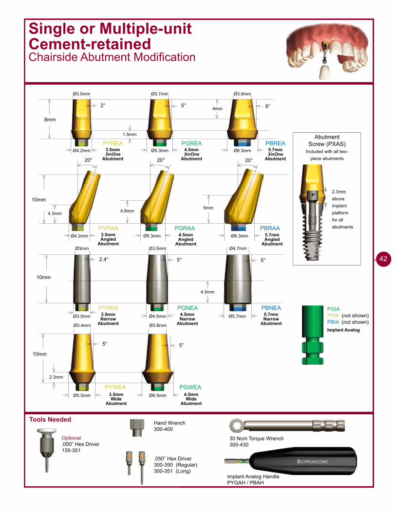
PYREA PGREA PBREA
8mm
2° 5° 8°
Ø4.2mm Ø5.3mm Ø6.3mm
PYRAA PGRAA PBRAA
10mm
20° 20° 20°
�mm4.8mm4.3mm
Ø4.2mm Ø5.3mm Ø6.3mm
�mm
1.5mm
Ø3.5mm Ø3.7mm Ø3.9mm
PYNEA PGNEA PBNEA
10mm
2.4° 5° 5°
Ø3.5mm Ø4.5mm Ø5.7mm
4.5mm
Ø�mm Ø3.5mm Ø4.7mm
PYWEA PGWEA
10mm
5° 5°
Ø6.5mmØ5.5mm
2.3mm
Ø3.4mm Ø3.8mm
PGIAPYIA (not shown)PBIA (not shown)
3.5mm 3inOne
Abutment
4.5mm 3inOne
Abutment
5.7mm 3inOne
Abutment
3.5mm Angled
Abutment
4.5mm Angled
Abutment
5.7mm Angled
Abutment
3.5mm Narrow
Abutment
4.5mm Narrow
Abutment
5.7mm Narrow
Abutment
3.5mm Wide
Abutment
4.5mm Wide
Abutment
Implant Analog
��
1 - 8 8 8 - 2 4 6 - 8 3 3 8
17
Make impression3 Clinical
P R E P A R E D A B U T M E N T I M P R E S S I O N
Prepared Abutment ImpressionClosed Tray, Crown & Bridge Technique
Syringe light or medium-bodied impression material around abutment. Use medium or heavy-bodied impression material in the tray. Make a full-arch crown & bridge impression with the elastomeric impression material of choice. Send the impression, an opposing model or impression and a bite registration to the laboratory for crown fabrication. For chair-side provisional fabrication, lightly lubricate the modified abutments and use the technique and material of choice.
Pour the standard crown & bridge impression in die stone. A reinforced die may be helpful if the preparation is extremely thin. Articulate and prepare according to standard laboratory procedures.
If the patient presents to you with the abutment in place, simply remove the temporary, if present, and proceed with the clinical step 2.
Remove the Healing Abutment from the implant with the .050” Hex Driver. Make sure the implant prosthetic platform is free of bone and soft tissue. Place the prepared abutment onto the implant and hand-tighten the Abutment Screw with the .050” Hex Driver. Take a radiograph along the long axis of the implant to ensure that the abutment is seated completely in the hex of the implant.
Torque the Abutment Screw to 30 Ncm using a calibrated Torque Wrench and the .050” Hex Driver. Counter-torque may be applied by grasping the abutment with an abutment clamp or hemostat.Block out the access holes on the top of the abutment with material of choice.The use of retraction cord may be necessary to ensure the transfer of the margins on the modified abutment.
Fabricate stone model4 Lab
Impression preparation2 Clinical
Remove provisional1 Clinical
Send to Lab
• Impression• Bite registration• Opposing model or impression• Shade
Tools Needed
P
P
P
8mm
�mm
��mm
�mm
PXAS
PXAS is used to secure the transfer coping.
P
PXBT may be used to increase the height of the transfer by 3mm.
P �mm
8mm
�mm
��mm
�mm
8mm
�mm
��mm
�mm
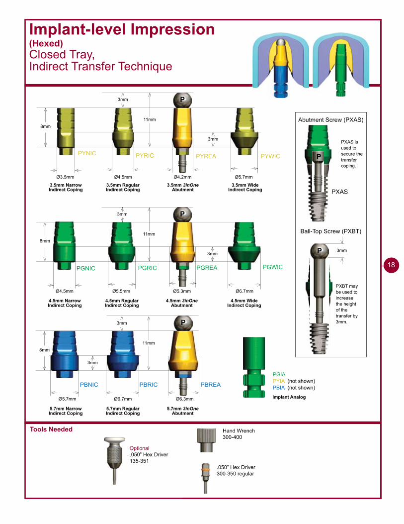
PYNIC
PGREA
PBREA
PYRIC PYWICPYREA
PGNIC PGRIC PGWIC
PBNIC PBRIC
Ø4.5mm Ø5.5mm Ø5.3mm Ø6.7mm
Ø6.7mmØ5.7mm Ø6.3mm
Ø4.2mmØ4.5mmØ3.5mm Ø5.7mm
PGIAPYIA (not shown)PBIA (not shown)
Abutment Screw (PXAS)
Ball-Top Screw (PXBT)
3.5mm Narrow Indirect Coping
3.5mm RegularIndirect Coping
3.5mm 3inOneAbutment
3.5mm WideIndirect Coping
4.5mm Narrow Indirect Coping
4.5mm RegularIndirect Coping
4.5mm 3inOneAbutment
4.5mm WideIndirect Coping
5.7mm Narrow Indirect Coping
5.7mm RegularIndirect Coping
5.7mm 3inOneAbutment
Implant Analog
Optional.050” Hex Driver135-351
Hand Wrench300-400
.050” Hex Driver300-350 regular
Implant-level Impression(Hexed)Closed Tray, Indirect Transfer Technique
18

1 - 8 8 8 - 2 4 6 - 8 3 3 8
�9
Implant-level Impression (Hexed)Closed Tray, Indirect Transfer Technique
Remove Healing Abutment1 Clinical
I M P L A N T - L E V E L I M P R E S S I O N - C L O S E D T R A Y
Place impression coping2 Clinical
Block out screw hole3 Clinical
Remove the Healing Abutment with the .050” Hex Driver. Make sure that the implant prosthetic platform is free of bone and soft tissue.
The emergence of the impression coping selected should match the emergence of the Healing Abutment and the intended final abutment (either narrow, regular or wide). Custom Cast emergence will be determined by the lab prescription.
Option A - Seat the 3inOne Abutment and secure it with a Ball-top Screw (hand-tighten).Option B - Seat the Indirect Transfer Coping and secure it with the included screw (hand-tighten).
If practical, orient the flat side of the abutment/coping to the facial for easier indexing.
Take a radiograph along the long axis of the implant to ensure the coping is fully seated.
Block out the hex hole on top of the Ball-top Screw (Option A); or the screw access hole of the Indirect Transfer Coping (Option B) with a material of choice.
Helpful Hint
When placing impression copings on multiple implants, remove one Healing Abutment at a time, replacing it immediately with the impression coping. This prevents the possibility of soft tissue collapsing onto the implant. Work from the posterior to the anterior.
Option A
Option B
Option A
Option B
20
I M P L A N T - L E V E L I M P R E S S I O N - C L O S E D T R A Y
Assemble analog 5Lab
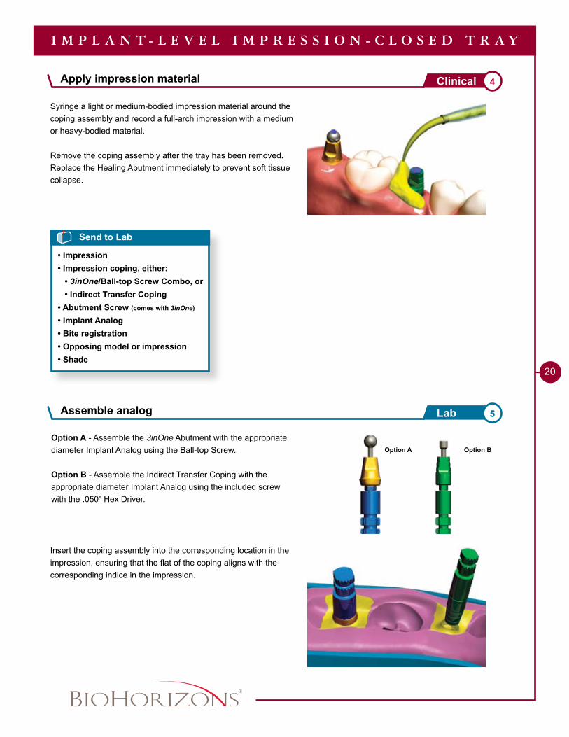
Apply impression material 4Clinical
Option A - Assemble the 3inOne Abutment with the appropriate diameter Implant Analog using the Ball-top Screw.
Option B - Assemble the Indirect Transfer Coping with the appropriate diameter Implant Analog using the included screw with the .050” Hex Driver.
Insert the coping assembly into the corresponding location in the impression, ensuring that the flat of the coping aligns with the corresponding indice in the impression.
Syringe a light or medium-bodied impression material around the coping assembly and record a full-arch impression with a medium or heavy-bodied material.
Remove the coping assembly after the tray has been removed. Replace the Healing Abutment immediately to prevent soft tissue collapse.
Send to Lab
• Impression• Impression coping, either: • 3inOne/Ball-top Screw Combo, or • Indirect Transfer Coping• Abutment Screw (comes with 3inOne)
• Implant Analog• Bite registration• Opposing model or impression• Shade
Option A Option B
1 - 8 8 8 - 2 4 6 - 8 3 3 8
2�
I M P L A N T - L E V E L I M P R E S S I O N - C L O S E D T R A Y
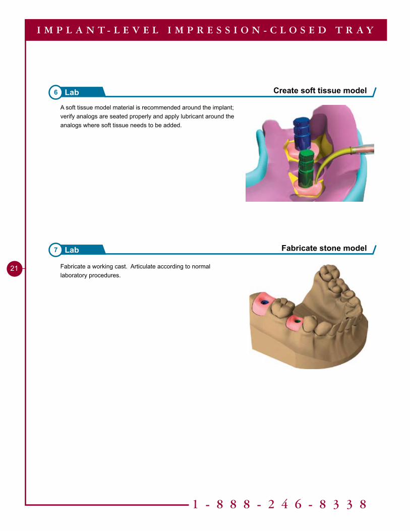
Fabricate stone model7 Lab
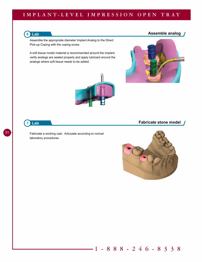
A soft tissue model material is recommended around the implant; verify analogs are seated properly and apply lubricant around the analogs where soft tissue needs to be added.
Create soft tissue model6 Lab
Fabricate a working cast. Articulate according to normal laboratory procedures.
Tools Needed
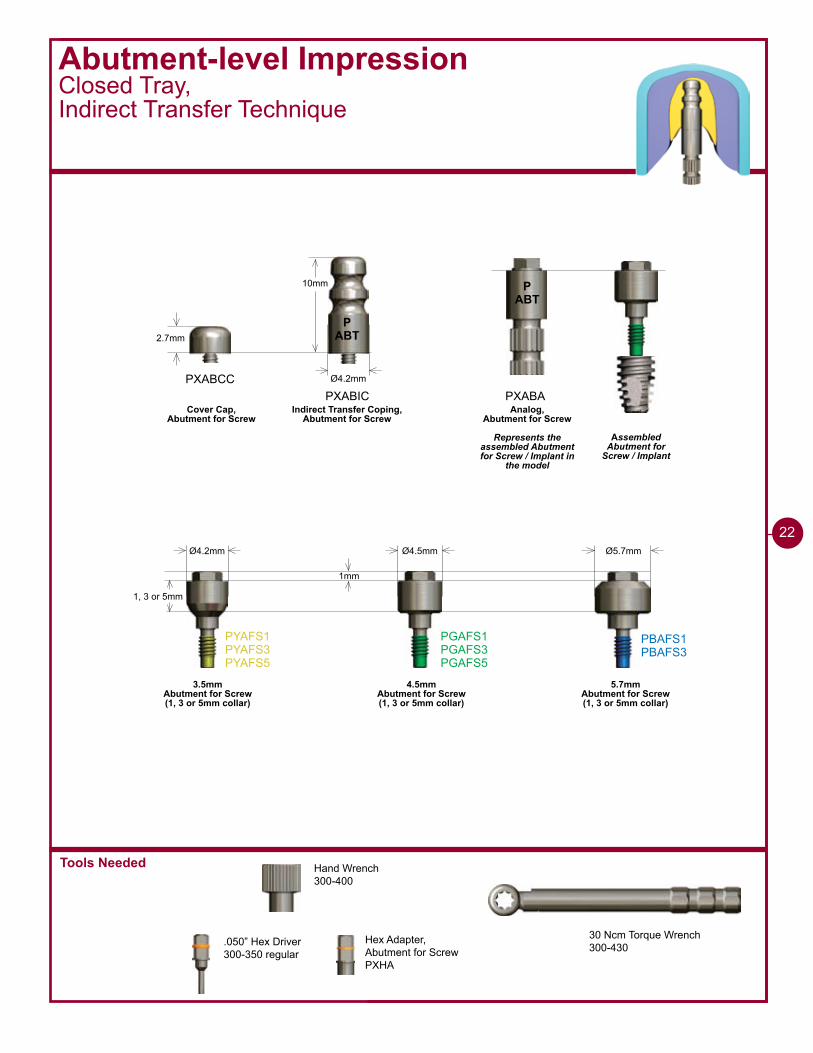
Abutment-level ImpressionClosed Tray, Indirect Transfer Technique
22
ABTP
Ø4.2mm
2.7mm
10mm
PXABCCPXABIC
Ø4.2mm Ø4.5mm Ø5.7mm
�mm
1, 3 or 5mm
PYAFS�PYAFS�PYAFS5
PGAFS�PGAFS�PGAFS5
PBAFS�PBAFS�
PXABA
30 Ncm Torque Wrench300-430
ABTP
Cover Cap,Abutment for Screw
Indirect Transfer Coping,Abutment for Screw
Analog,Abutment for Screw
Represents the assembled Abutment for Screw / Implant in
the model
3.5mmAbutment for Screw (1, 3 or 5mm collar)
4.5mmAbutment for Screw (1, 3 or 5mm collar)
5.7mmAbutment for Screw (1, 3 or 5mm collar)
Assembled Abutment for
Screw / Implant
Hand Wrench300-400
.050” Hex Driver300-350 regular
Hex Adapter,Abutment for ScrewPXHA
1 - 8 8 8 - 2 4 6 - 8 3 3 8
2�
Abutment-level ImpressionClosed Tray,Indirect Transfer Technique
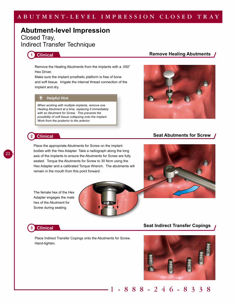
Place Indirect Transfer Copings onto the Abutments for Screw. Hand-tighten.
Remove Healing Abutments1 Clinical
Seat Abutments for Screw2 Clinical
Seat Indirect Transfer Copings3 Clinical
A B U T M E N T - L E V E L I M P R E S S I O N C L O S E D T R A Y
Remove the Healing Abutments from the implants with a .050” Hex Driver. Make sure the implant prosthetic platform is free of bone and soft tissue. Irrigate the internal thread connection of the implant and dry.
Place the appropriate Abutments for Screw on the implant bodies with the Hex Adapter. Take a radiograph along the long axis of the implants to ensure the Abutments for Screw are fully seated. Torque the Abutments for Screw to 30 Ncm using the Hex Adapter and a calibrated Torque Wrench. The abutments will remain in the mouth from this point forward.
Helpful Hint
When working with multiple implants, remove one Healing Abutment at a time, replacing it immediately with an Abutment for Screw. This prevents the possibility of soft tissue collapsing onto the implant. Work from the posterior to the anterior.
The female hex of the Hex Adapter engages the male hex of the Abutment for Screw during seating.
2�
Make an impression 4Clinical
Make an impression 5Clinical
Place Cover Caps 6Clinical
A B U T M E N T - L E V E L I M P R E S S I O N C L O S E D T R A Y
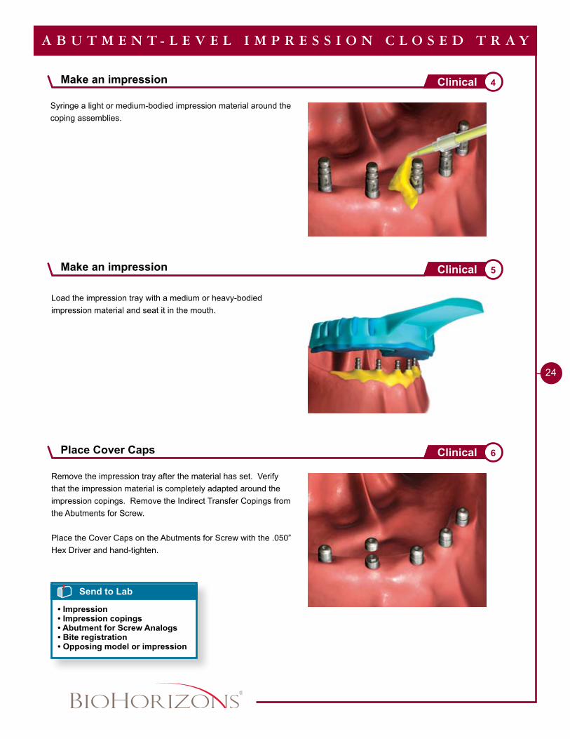
Remove the impression tray after the material has set. Verify that the impression material is completely adapted around the impression copings. Remove the Indirect Transfer Copings from the Abutments for Screw.
Place the Cover Caps on the Abutments for Screw with the .050” Hex Driver and hand-tighten.
Syringe a light or medium-bodied impression material around the coping assemblies.
Load the impression tray with a medium or heavy-bodied impression material and seat it in the mouth.
Send to Lab
• Impression• Impression copings• Abutment for Screw Analogs• Bite registration• Opposing model or impression
ABTP
1 - 8 8 8 - 2 4 6 - 8 3 3 8
25
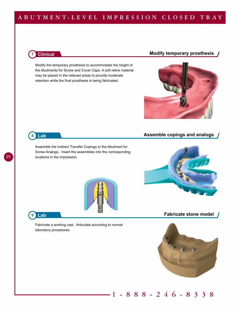
Modify the temporary prosthesis to accommodate the height of the Abutments for Screw and Cover Caps. A soft reline material may be placed in the relieved areas to provide moderate retention while the final prosthesis is being fabricated.
Modify temporary prosthesis7 Clinical
Assemble copings and analogs8 Lab
Fabricate stone model9 Lab
A B U T M E N T - L E V E L I M P R E S S I O N C L O S E D T R A Y
Fabricate a working cast. Articulate according to normal laboratory procedures.
Assemble the Indirect Transfer Copings to the Abutment for Screw Analogs. Insert the assemblies into the corresponding locations in the impression.
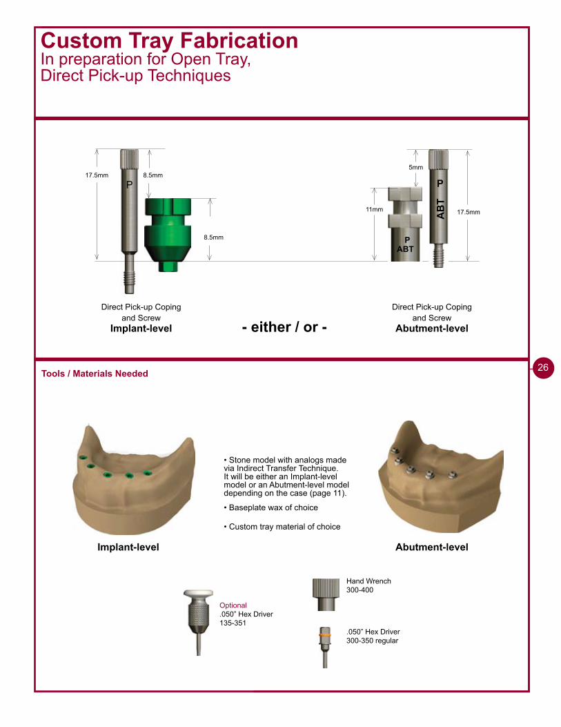
Custom Tray FabricationIn preparation for Open Tray,Direct Pick-up Techniques
17.5mm 8.5mm
P
Direct Pick-up Coping and Screw
Implant-level
Direct Pick-up Coping and Screw
Abutment-level
8.5mm
• Stone model with analogs made via Indirect Transfer Technique. It will be either an Implant-level model or an Abutment-level model depending on the case (page 11).
Tools / Materials Needed
• Baseplate wax of choice
• Custom tray material of choice
Implant-level Abutment-level
2�
- either / or -
AB
T
P
ABTP
11mm 17.5mm
5mm
Optional.050” Hex Driver135-351
Hand Wrench300-400
.050” Hex Driver300-350 regular
1 - 8 8 8 - 2 4 6 - 8 3 3 8
27
Custom Tray FabricationIn preparation for Open Tray,Direct Pick-up Techniques
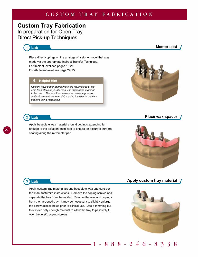
Apply custom tray material around baseplate wax and cure per the manufacturer’s instructions. Remove the coping screws and separate the tray from the model. Remove the wax and copings from the hardened tray. It may be necessary to slightly enlarge the screw access holes prior to clinical use. Use a trimming bur to remove only enough material to allow the tray to passively fit over the in situ coping screws.
Place direct copings on the analogs of a stone model that was made via the appropriate Indirect Transfer Technique.For Implant-level see pages 18-21.For Abutment-level see page 22-25.
Apply baseplate wax material around copings extending far enough to the distal on each side to ensure an accurate intraoral seating along the retromolar pad.
Helpful Hint
Custom trays better approximate the morphology of the arch than stock trays, allowing less impression material to be used. This results in a more accurate impression and subsequent stone model, making it easier to create a passive fitting restoration.
Master cast1 Lab
Place wax spacer2 Lab
Apply custom tray material3 Lab
C U S T O M T R A Y F A B R I C A T I O N
Tools Needed
9mm
5mm
9mm
5mm
9mm
5mm
17.5mm 8.5mm
P
5mm
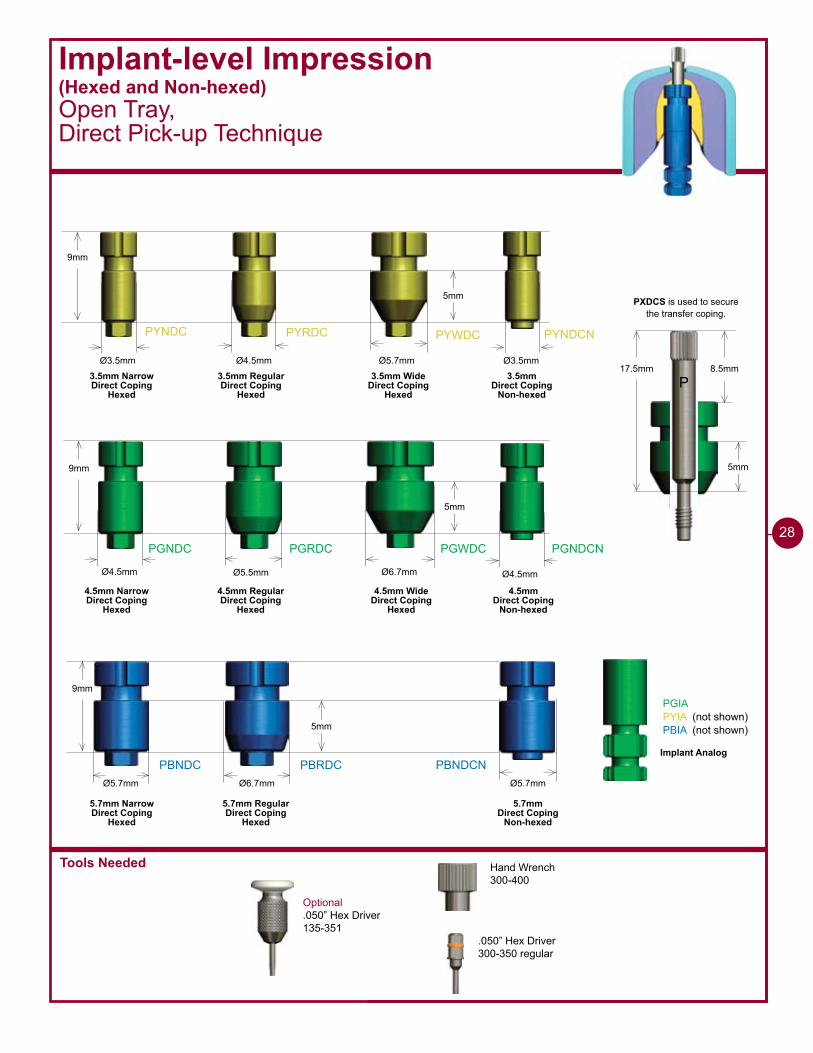
PXDCS is used to secure the transfer coping.
PYNDC PYRDC PYWDC PYNDCN
PGNDC PGRDC PGWDC PGNDCN
PBNDC PBRDC PBNDCN
Ø4.5mm Ø5.5mm Ø6.7mm
Ø6.7mmØ5.7mm
Ø4.5mmØ3.5mm Ø5.7mm Ø3.5mm
Ø4.5mm
Ø5.7mm
PGIAPYIA (not shown)PBIA (not shown)
3.5mm Narrow Direct Coping
Hexed
3.5mm RegularDirect Coping
Hexed
3.5mm WideDirect Coping
Hexed
3.5mm Direct Coping
Non-hexed
4.5mm Narrow Direct Coping
Hexed
4.5mm RegularDirect Coping
Hexed
4.5mm WideDirect Coping
Hexed
4.5mm Direct Coping
Non-hexed
5.7mm Narrow Direct Coping
Hexed
5.7mm RegularDirect Coping
Hexed
5.7mm Direct Coping
Non-hexed
Implant Analog
Implant-level Impression(Hexed and Non-hexed)Open Tray, Direct Pick-up Technique
Optional.050” Hex Driver135-351
Hand Wrench300-400
.050” Hex Driver300-350 regular
28
1 - 8 8 8 - 2 4 6 - 8 3 3 8
29
Implant-level Impression (Hexed and Non-hexed)Open Tray, Direct Pick-up Technique
Remove Healing Abutment1 Clinical
Place impression coping2 Clinical
I M P L A N T - L E V E L I M P R E S S I O N O P E N T R A Y
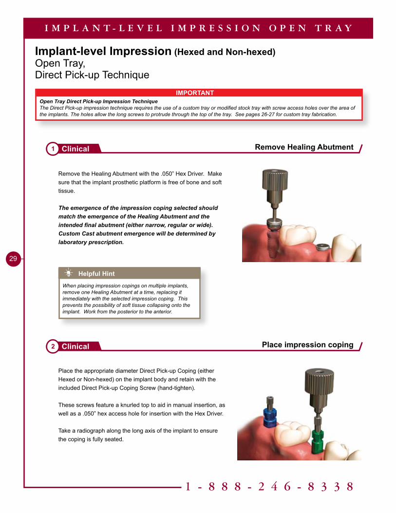
Remove the Healing Abutment with the .050” Hex Driver. Make sure that the implant prosthetic platform is free of bone and soft tissue.
The emergence of the impression coping selected should match the emergence of the Healing Abutment and the intended final abutment (either narrow, regular or wide). Custom Cast abutment emergence will be determined by laboratory prescription.
Place the appropriate diameter Direct Pick-up Coping (either Hexed or Non-hexed) on the implant body and retain with the included Direct Pick-up Coping Screw (hand-tighten).
These screws feature a knurled top to aid in manual insertion, as well as a .050” hex access hole for insertion with the Hex Driver.
Take a radiograph along the long axis of the implant to ensure the coping is fully seated.
Helpful Hint
When placing impression copings on multiple implants, remove one Healing Abutment at a time, replacing it immediately with the selected impression coping. This prevents the possibility of soft tissue collapsing onto the implant. Work from the posterior to the anterior.
IMPORTANTOpen Tray Direct Pick-up Impression TechniqueThe Direct Pick-up impression technique requires the use of a custom tray or modified stock tray with screw access holes over the area of the implants. The holes allow the long screws to protrude through the top of the tray. See pages 26-27 for custom tray fabrication.
30
Make an impression 4Clinical
Remove coping screws 5Clinical
Try-in impression tray 3Clinical
I M P L A N T - L E V E L I M P R E S S I O N O P E N T R A Y
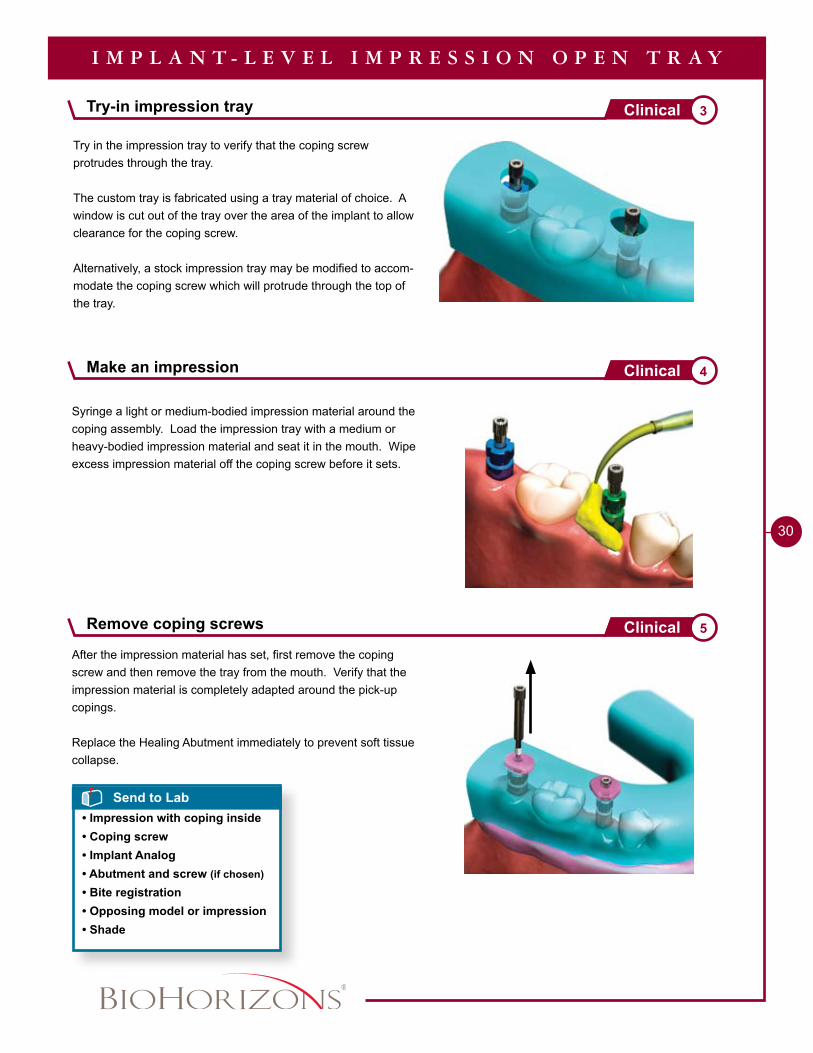
Try in the impression tray to verify that the coping screw protrudes through the tray.
The custom tray is fabricated using a tray material of choice. A window is cut out of the tray over the area of the implant to allow clearance for the coping screw.
Alternatively, a stock impression tray may be modified to accom-modate the coping screw which will protrude through the top of the tray.
After the impression material has set, first remove the coping screw and then remove the tray from the mouth. Verify that the impression material is completely adapted around the pick-up copings.
Replace the Healing Abutment immediately to prevent soft tissue collapse.
Syringe a light or medium-bodied impression material around the coping assembly. Load the impression tray with a medium or heavy-bodied impression material and seat it in the mouth. Wipe excess impression material off the coping screw before it sets.
Send to Lab• Impression with coping inside• Coping screw• Implant Analog• Abutment and screw (if chosen)
• Bite registration• Opposing model or impression• Shade
1 - 8 8 8 - 2 4 6 - 8 3 3 8
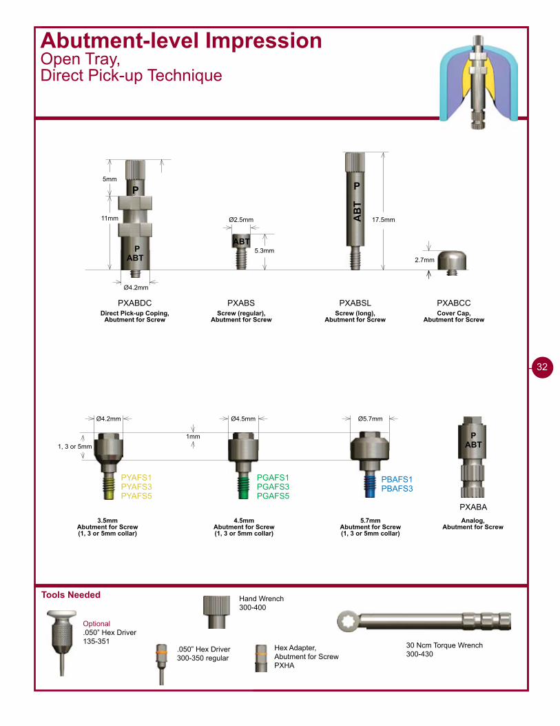
�� Fabricate a working cast. Articulate according to normal laboratory procedures.
Fabricate stone model7 Lab
Assemble analog6 Lab
I M P L A N T - L E V E L I M P R E S S I O N O P E N T R A Y
Assemble the appropriate diameter Implant Analog to the Direct Pick-up Coping with the coping screw.
A soft tissue model material is recommended around the implant; verify analogs are seated properly and apply lubricant around the analogs where soft tissue needs to be added.
Tools Needed
Abutment-level ImpressionOpen Tray, Direct Pick-up Technique
Optional.050” Hex Driver135-351
�2
2.7mmABTP
Ø4.2mm
��mm AB
T
P
17.5mm
PXABDC PXABSL
P5mm
ABT5.3mm
Ø2.5mm
PXABS
Ø4.2mm Ø4.5mm Ø5.7mm
�mm1, 3 or 5mm
PYAFS�PYAFS�PYAFS5
PGAFS�PGAFS�PGAFS5
PBAFS�PBAFS�
PXABA
PXABCC
ABTP
3.5mmAbutment for Screw (1, 3 or 5mm collar)
4.5mmAbutment for Screw (1, 3 or 5mm collar)
5.7mmAbutment for Screw (1, 3 or 5mm collar)
Direct Pick-up Coping,Abutment for Screw
Screw (regular),Abutment for Screw
Screw (long),Abutment for Screw
Analog,Abutment for Screw
Cover Cap,Abutment for Screw
30 Ncm Torque Wrench300-430
Hand Wrench300-400
.050” Hex Driver300-350 regular
Hex Adapter,Abutment for ScrewPXHA
Abutment-level ImpressionOpen Tray, Direct Pick-up Technique
1 - 8 8 8 - 2 4 6 - 8 3 3 8
��
IMPORTANTOpen Tray Direct Pick-up Impression TechniqueThe Direct Pick-up impression technique requires the use of a custom tray or modified stock tray with screw access holes over the area of the implants. The holes allow the long screws to protrude through the top of the tray. See pages 26-27 for custom tray fabrication.
Remove Healing Abutment1 Clinical
Seat Abutments for Screw2 Clinical
A B U T M E N T - L E V E L I M P R E S S I O N O P E N T R A Y
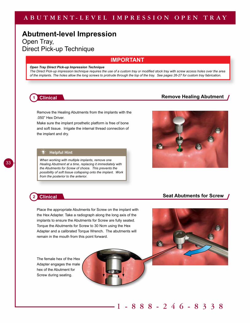
Remove the Healing Abutments from the implants with the .050” Hex Driver. Make sure the implant prosthetic platform is free of bone and soft tissue. Irrigate the internal thread connection of the implant and dry.
Place the appropriate Abutments for Screw on the implant with the Hex Adapter. Take a radiograph along the long axis of the implants to ensure the Abutments for Screw are fully seated. Torque the Abutments for Screw to 30 Ncm using the Hex Adapter and a calibrated Torque Wrench. The abutments will remain in the mouth from this point forward.
The female hex of the Hex Adapter engages the male hex of the Abutment for Screw during seating.
Helpful Hint
When working with multiple implants, remove one Healing Abutment at a time, replacing it immediately with the Abutments for Screw of choice. This prevents the possibility of soft tissue collapsing onto the implant. Work from the posterior to the anterior.
��
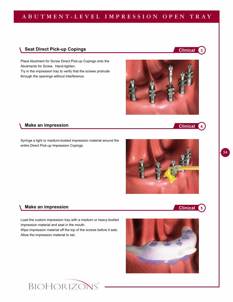
Place Abutment for Screw Direct Pick-up Copings onto the Abutments for Screw. Hand-tighten. Try in the impression tray to verify that the screws protrude through the openings without interference.
A B U T M E N T - L E V E L I M P R E S S I O N O P E N T R A Y
Load the custom impression tray with a medium or heavy-bodied impression material and seat in the mouth.Wipe impression material off the top of the screws before it sets. Allow the impression material to set.
Syringe a light or medium-bodied impression material around the entire Direct Pick-up Impression Copings.
Make an impression 4Clinical
Make an impression 5Clinical
Seat Direct Pick-up Copings 3Clinical
1 - 8 8 8 - 2 4 6 - 8 3 3 8
35
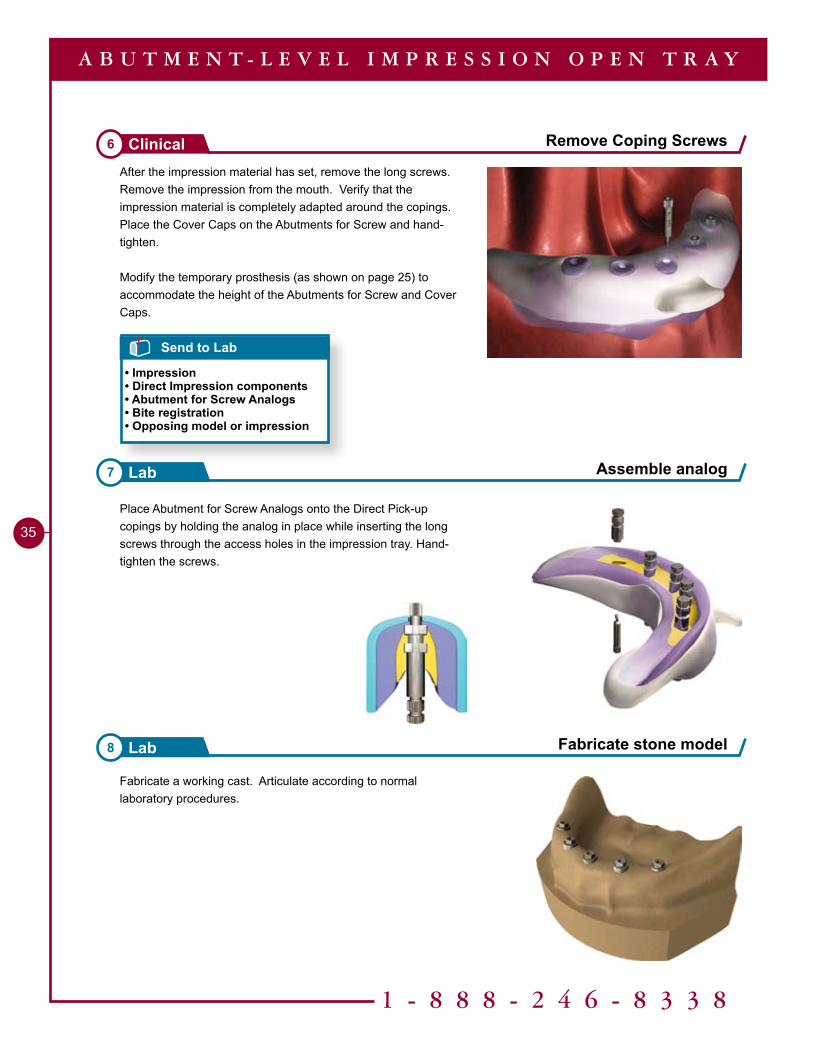
Fabricate a working cast. Articulate according to normal laboratory procedures.
Place Abutment for Screw Analogs onto the Direct Pick-up copings by holding the analog in place while inserting the long screws through the access holes in the impression tray. Hand-tighten the screws.
Fabricate stone model8 Lab
Assemble analog7 Lab
After the impression material has set, remove the long screws. Remove the impression from the mouth. Verify that the impression material is completely adapted around the copings. Place the Cover Caps on the Abutments for Screw and hand-tighten.
Modify the temporary prosthesis (as shown on page 25) to accommodate the height of the Abutments for Screw and Cover Caps.
Send to Lab
• Impression• Direct Impression components• Abutment for Screw Analogs• Bite registration• Opposing model or impression
Remove Coping Screws6 Clinical
A B U T M E N T - L E V E L I M P R E S S I O N O P E N T R A Y
Tools Needed
1, 3 or 5mm
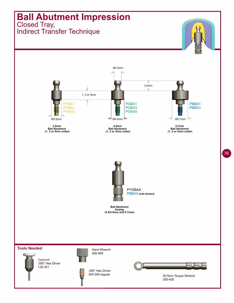
Ø3.5mm Ø4.5mm Ø5.7mm
Ø2.5mm
3.5mm
PYBA�PYBA�PYBA5
PGBA�PGBA�PGBA5
PBBA�PBBA�
PYGBAAPBBAA (not shown)
3.5mmBall Abutment
(1, 3 or 5mm collar)
4.5mmBall Abutment
(1, 3 or 5mm collar)
5.7mmBall Abutment
(1, 3 or 5mm collar)
Ball AbutmentAnalog
(3.5/4.5mm and 5.7mm)
Ball Abutment ImpressionClosed Tray,Indirect Transfer Technique
Optional.050” Hex Driver135-351
Hand Wrench300-400
.050” Hex Driver300-350 regular 30 Ncm Torque Wrench
300-430
��
1 - 8 8 8 - 2 4 6 - 8 3 3 8
37
Ball Abutment ImpressionClosed Tray,Indirect Transfer Technique
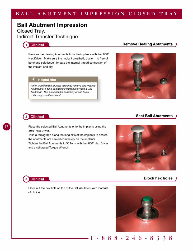
Block out the hex hole on top of the Ball Abutment with material of choice.
Remove Healing Abutments1 Clinical
Seat Ball Abutments2 Clinical
Block hex holes3 Clinical
B A L L A B U T M E N T I M P R E S S I O N C L O S E D T R A Y
Remove the Healing Abutments from the implants with the .050” Hex Driver. Make sure the implant prosthetic platform is free of bone and soft tissue. Irrigate the internal thread connection of the implant and dry.
Place the selected Ball Abutments onto the implants using the .050” Hex Driver.Take a radiograph along the long axis of the implants to ensure the abutments are seated completely on the implants.Tighten the Ball Abutments to 30 Ncm with the .050” Hex Driver and a calibrated Torque Wrench.
Helpful Hint
When working with multiple implants, remove one Healing Abutment at a time, replacing it immediately with a Ball Abutment. This prevents the possibility of soft tissue collapsing onto the implant.
38
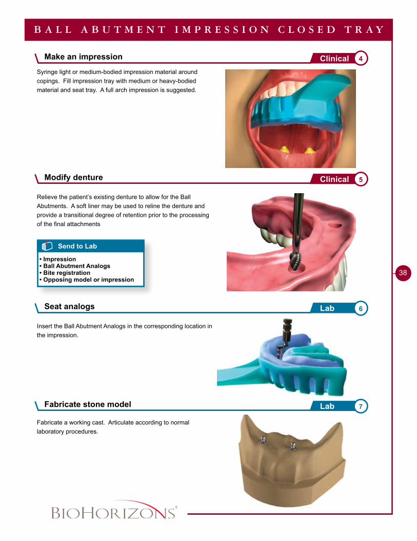
Syringe light or medium-bodied impression material around copings. Fill impression tray with medium or heavy-bodied material and seat tray. A full arch impression is suggested.
Relieve the patient’s existing denture to allow for the Ball Abutments. A soft liner may be used to reline the denture and provide a transitional degree of retention prior to the processing of the final attachments
Seat analogs 6Lab
Fabricate stone model 7Lab
Send to Lab
• Impression• Ball Abutment Analogs• Bite registration• Opposing model or impression
B A L L A B U T M E N T I M P R E S S I O N C L O S E D T R A Y
Insert the Ball Abutment Analogs in the corresponding location in the impression.
Fabricate a working cast. Articulate according to normal laboratory procedures.
Make an impression 4Clinical
Modify denture 5Clinical
1 - 8 8 8 - 2 4 6 - 8 3 3 8
�9
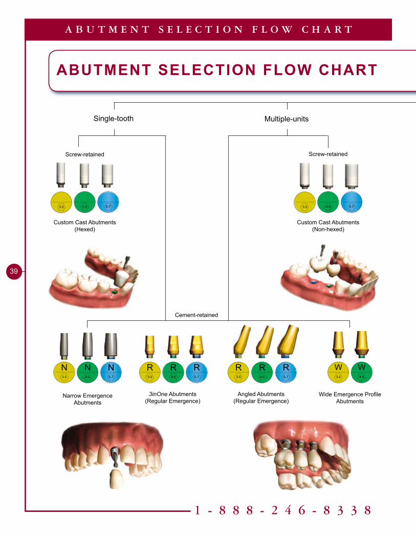
A B U T M E N T S E L E C T I O N F L O W C H A R T
ABUTMENT SELECTION FLOW CHART
Single-tooth Multiple-units
Custom Cast Abutments(Hexed)
Screw-retained
Cement-retained
Screw-retained
Custom Cast Abutments (Non-hexed)
Narrow EmergenceAbutments
N3.5
N5.7
N4.5
3inOne Abutments(Regular Emergence)
R3.5
R5.7
R4.5
Wide Emergence Profile Abutments
W3.5
W4.5
Angled Abutments(Regular Emergence)
R3.5
R5.7
R4.5
3.5 5.74.5 3.5 5.74.5
40
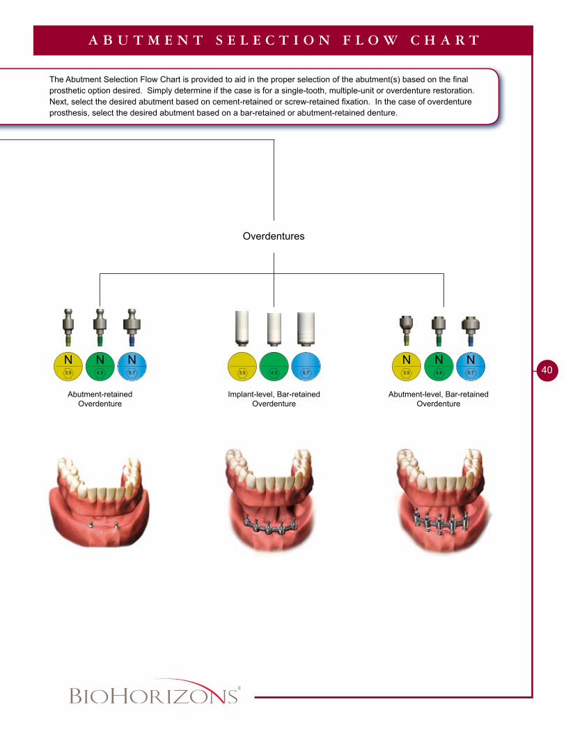
A B U T M E N T S E L E C T I O N F L O W C H A R T
The Abutment Selection Flow Chart is provided to aid in the proper selection of the abutment(s) based on the final prosthetic option desired. Simply determine if the case is for a single-tooth, multiple-unit or overdenture restoration. Next, select the desired abutment based on cement-retained or screw-retained fixation. In the case of overdenture prosthesis, select the desired abutment based on a bar-retained or abutment-retained denture.
Overdentures
Implant-level, Bar-retainedOverdenture
Abutment-retainedOverdenture
Abutment-level, Bar-retainedOverdenture
N3.5
N5.7
N4.5 3.5 5.74.5
N3.5
N5.7
N4.5
Single or Multiple-unit Cement-retained - Chairside Abutment Modification
Single-tooth Screw-retained - Custom Cast Abutment
Single-tooth Cement-retained - Laboratory Prepared Abutment
Multiple-unit Screw-retained - Custom Cast Abutments
Multiple-unit Cement-retained - Laboratory Prepared Abutments
Ball Abutment Overdenture - Existing Denture, Chairside Pick-up
Ball Abutment Overdenture - New Denture
Bar Overdenture - Screw-retained Implant or Abutment-level Cast Bar
Bar Overdenture - Screw-retained Laser Welded Bar
�2
48
54
60
��
70
74
78
86
Restorative TechniquesTable of Contents
1 - 8 8 8 - 2 4 6 - 8 3 3 8
��
Tools Needed
Implant Analog HandlePYGAH / PBAH
Optional.050” Hex Driver135-351
Single or Multiple-unitCement-retained Chairside Abutment Modification
2.3mmaboveimplantplatformfor allabutments
Abutment Screw (PXAS)
Included with all two-piece abutments
P
PYREA PGREA PBREA
8mm
2° 5° 8°
Ø4.2mm Ø5.3mm Ø6.3mm
PYRAA PGRAA PBRAA
10mm
20° 20° 20°
�mm4.8mm4.3mm
Ø4.2mm Ø5.3mm Ø6.3mm
�mm
1.5mm
Ø3.5mm Ø3.7mm Ø3.9mm
PYNEA PGNEA PBNEA
10mm
2.4° 5° 5°
Ø3.5mm Ø4.5mm Ø5.7mm
4.5mm
Ø�mm Ø3.5mm Ø4.7mm
PYWEA PGWEA
10mm
5° 5°
Ø6.5mmØ5.5mm
2.3mm
Ø3.4mm Ø3.8mm
PGIAPYIA (not shown)PBIA (not shown)
3.5mm 3inOne
Abutment
4.5mm 3inOne
Abutment
5.7mm 3inOne
Abutment
3.5mm Angled
Abutment
4.5mm Angled
Abutment
5.7mm Angled
Abutment
3.5mm Narrow
Abutment
4.5mm Narrow
Abutment
5.7mm Narrow
Abutment
3.5mm Wide
Abutment
4.5mm Wide
Abutment
Implant Analog
30 Ncm Torque Wrench300-430
Hand Wrench300-400
.050” Hex Driver300-350 (Regular)300-351 (Long)
�2
1 - 8 8 8 - 2 4 6 - 8 3 3 8
��
Single or Multiple-unitCement-retainedChairside Abutment Modification
Remove Healing Abutment and seat selected abutment1 Clinical
Mark required adjustments2 Clinical
Replace Healing Abutment3 Clinical
C E M E N T - R E T A I N E D S I N G L E / M U L T I P L E - U N I T
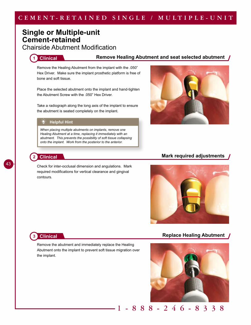
Remove the Healing Abutment from the implant with the .050” Hex Driver. Make sure the implant prosthetic platform is free of bone and soft tissue.
Place the selected abutment onto the implant and hand-tighten the Abutment Screw with the .050” Hex Driver.
Take a radiograph along the long axis of the implant to ensure the abutment is seated completely on the implant.
Check for inter-occlusal dimension and angulations. Mark required modifications for vertical clearance and gingival contours.
Remove the abutment and immediately replace the Healing Abutment onto the implant to prevent soft tissue migration over the implant.
Helpful Hint
When placing multiple abutments on implants, remove one Healing Abutment at a time, replacing it immediately with an abutment. This prevents the possibility of soft tissue collapsing onto the implant. Work from the posterior to the anterior.
��
C E M E N T - R E T A I N E D S I N G L E / M U L T I P L E - U N I T
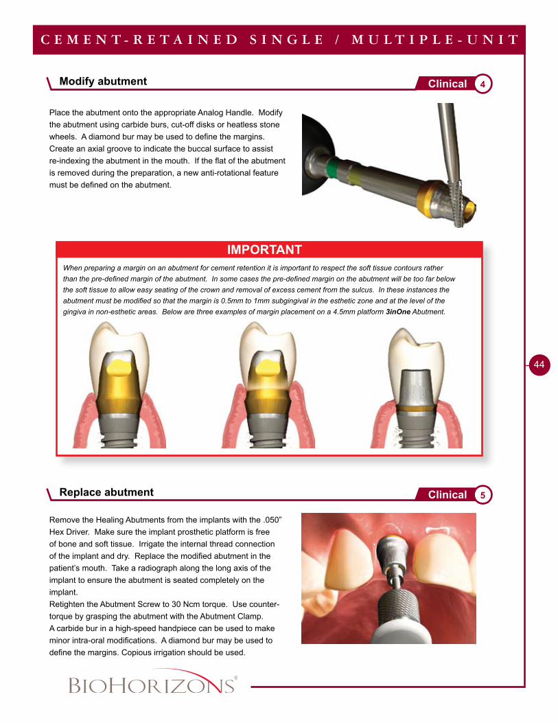
IMPORTANTWhen preparing a margin on an abutment for cement retention it is important to respect the soft tissue contours rather than the pre-defined margin of the abutment. In some cases the pre-defined margin on the abutment will be too far below the soft tissue to allow easy seating of the crown and removal of excess cement from the sulcus. In these instances the abutment must be modified so that the margin is 0.5mm to 1mm subgingival in the esthetic zone and at the level of the gingiva in non-esthetic areas. Below are three examples of margin placement on a 4.5mm platform 3inOne Abutment.
Place the abutment onto the appropriate Analog Handle. Modify the abutment using carbide burs, cut-off disks or heatless stone wheels. A diamond bur may be used to define the margins. Create an axial groove to indicate the buccal surface to assist re-indexing the abutment in the mouth. If the flat of the abutment is removed during the preparation, a new anti-rotational feature must be defined on the abutment.
Remove the Healing Abutments from the implants with the .050” Hex Driver. Make sure the implant prosthetic platform is free of bone and soft tissue. Irrigate the internal thread connection of the implant and dry. Replace the modified abutment in the patient’s mouth. Take a radiograph along the long axis of the implant to ensure the abutment is seated completely on the implant.Retighten the Abutment Screw to 30 Ncm torque. Use counter-torque by grasping the abutment with the Abutment Clamp.A carbide bur in a high-speed handpiece can be used to make minor intra-oral modifications. A diamond bur may be used to define the margins. Copious irrigation should be used.
Modify abutment 4Clinical
Replace abutment 5Clinical
1 - 8 8 8 - 2 4 6 - 8 3 3 8
45
Place provisional crown7 Clinical
Pour working cast8 Lab
Wax on model9 Lab
C E M E N T - R E T A I N E D S I N G L E / M U L T I P L E - U N I T
Send to Lab
• Impression• Bite registration• Opposing model or impression
Make an impression6 Clinical
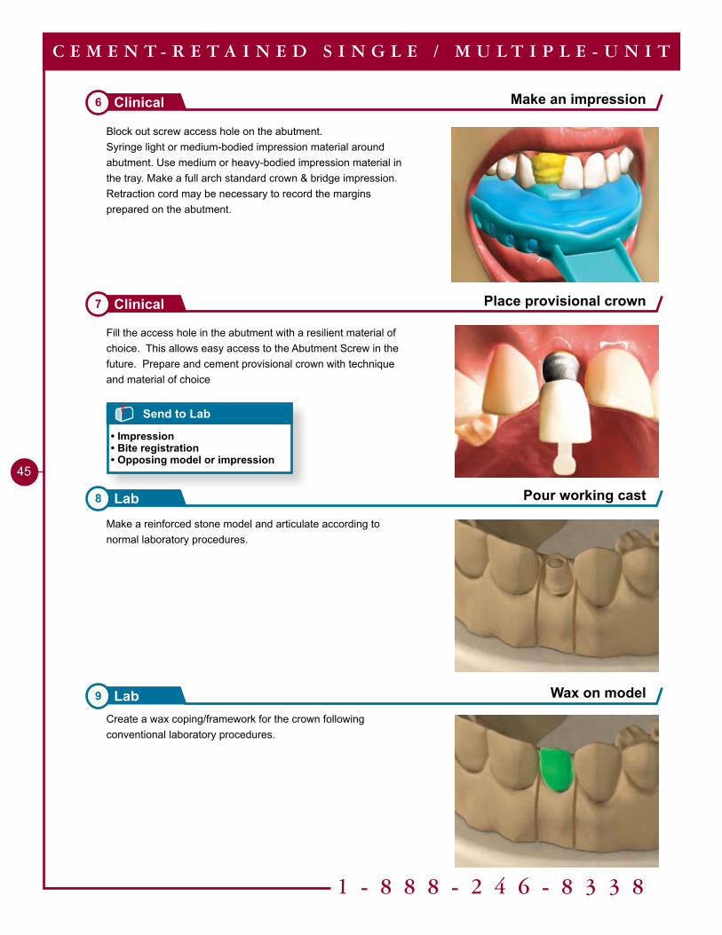
Make a reinforced stone model and articulate according to normal laboratory procedures.
Fill the access hole in the abutment with a resilient material of choice. This allows easy access to the Abutment Screw in the future. Prepare and cement provisional crown with technique and material of choice
Create a wax coping/framework for the crown following conventional laboratory procedures.
Block out screw access hole on the abutment.Syringe light or medium-bodied impression material around abutment. Use medium or heavy-bodied impression material in the tray. Make a full arch standard crown & bridge impression.Retraction cord may be necessary to record the margins prepared on the abutment.
��
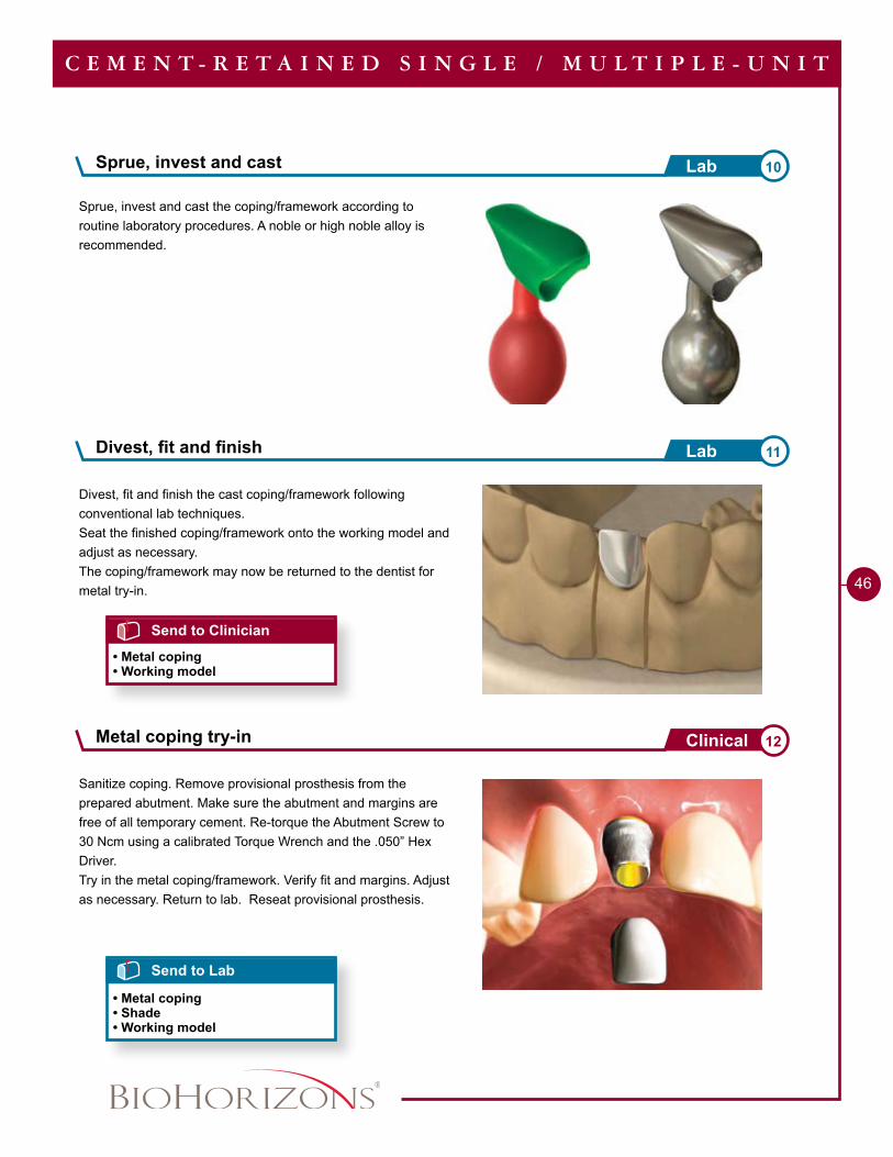
Sanitize coping. Remove provisional prosthesis from the prepared abutment. Make sure the abutment and margins are free of all temporary cement. Re-torque the Abutment Screw to 30 Ncm using a calibrated Torque Wrench and the .050” Hex Driver.Try in the metal coping/framework. Verify fit and margins. Adjust as necessary. Return to lab. Reseat provisional prosthesis.
Divest, fit and finish the cast coping/framework following conventional lab techniques.Seat the finished coping/framework onto the working model and adjust as necessary.The coping/framework may now be returned to the dentist for metal try-in.
Divest, fit and finish 11Lab
Send to Lab
• Metal coping• Shade• Working model
C E M E N T - R E T A I N E D S I N G L E / M U L T I P L E - U N I T
Send to Clinician
• Metal coping• Working model
Sprue, invest and cast 10Lab
Sprue, invest and cast the coping/framework according to routine laboratory procedures. A noble or high noble alloy is recommended.
Metal coping try-in 12Clinical
1 - 8 8 8 - 2 4 6 - 8 3 3 8
47
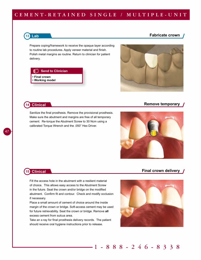
Sanitize the final prosthesis. Remove the provisional prosthesis. Make sure the abutment and margins are free of all temporary cement. Re-torque the Abutment Screw to 30 Ncm using a calibrated Torque Wrench and the .050” Hex Driver.
Remove temporary14 Clinical
Final crown delivery15 Clinical
C E M E N T - R E T A I N E D S I N G L E / M U L T I P L E - U N I T
Fill the access hole in the abutment with a resilient material of choice. This allows easy access to the Abutment Screw in the future. Seat the crown and/or bridge on the modified abutment. Confirm fit and contour. Check and modify occlusion if necessary. Place a small amount of cement of choice around the inside margin of the crown or bridge. Soft-access cement may be used for future retrievability. Seat the crown or bridge. Remove all excess cement from sulcus area.Take an x-ray for final prosthesis delivery records. The patient should receive oral hygiene instructions prior to release.
Prepare coping/framework to receive the opaque layer according to routine lab procedures. Apply veneer material and finish. Polish metal margins as routine. Return to clinician for patient delivery.
Send to Clinician
• Final crown• Working model
Fabricate crown13 Lab
Tools Needed
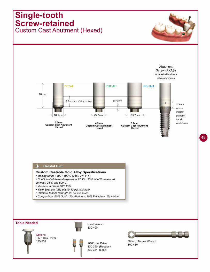
PYCAH PGCAH PBCAH
10mm
Ø4.2mm
0.75mm
Ø4.5mm Ø5.7mm
3.6mm (top of alloy coping)
3.5mmCustom Cast Abutment
Hexed4.5mm
Custom Cast Abutment Hexed
5.7mmCustom Cast Abutment
Hexed
Single-toothScrew-retainedCustom Cast Abutment (Hexed)
Optional.050” Hex Driver135-351
P 2.3mmaboveimplantplatformfor allabutments
Abutment Screw (PXAS)
Included with all two-piece abutments
30 Ncm Torque Wrench300-430
Hand Wrench300-400
.050” Hex Driver300-350 (Regular)300-351 (Long)
48
Helpful Hint
Custom Castable Gold Alloy Specifications• Melting range 1400-1490°C (2552-2714° F)• Coefficient of thermal expansion 12.45 x 10⁻⁶ in/in°C measured between 25°C and 500°C• Vickers Hardness HV5 205• Yield Strength (.2% offset) 83 psi minimum• Ultimate Tensile Strength 92 psi minimum• Composition: 60% Gold, 19% Platinum, 20% Palladium, 1% Iridium
1 - 8 8 8 - 2 4 6 - 8 3 3 8
�9
Single-toothScrew-retained Custom Cast Abutment (Hexed)
Pour working cast1 Lab
Seat the Custom Cast Abutment2 Lab
Modify Custom Cast Abutment3 Lab
S I N G L E - T O O T H S C R E W - R E T A I N E D
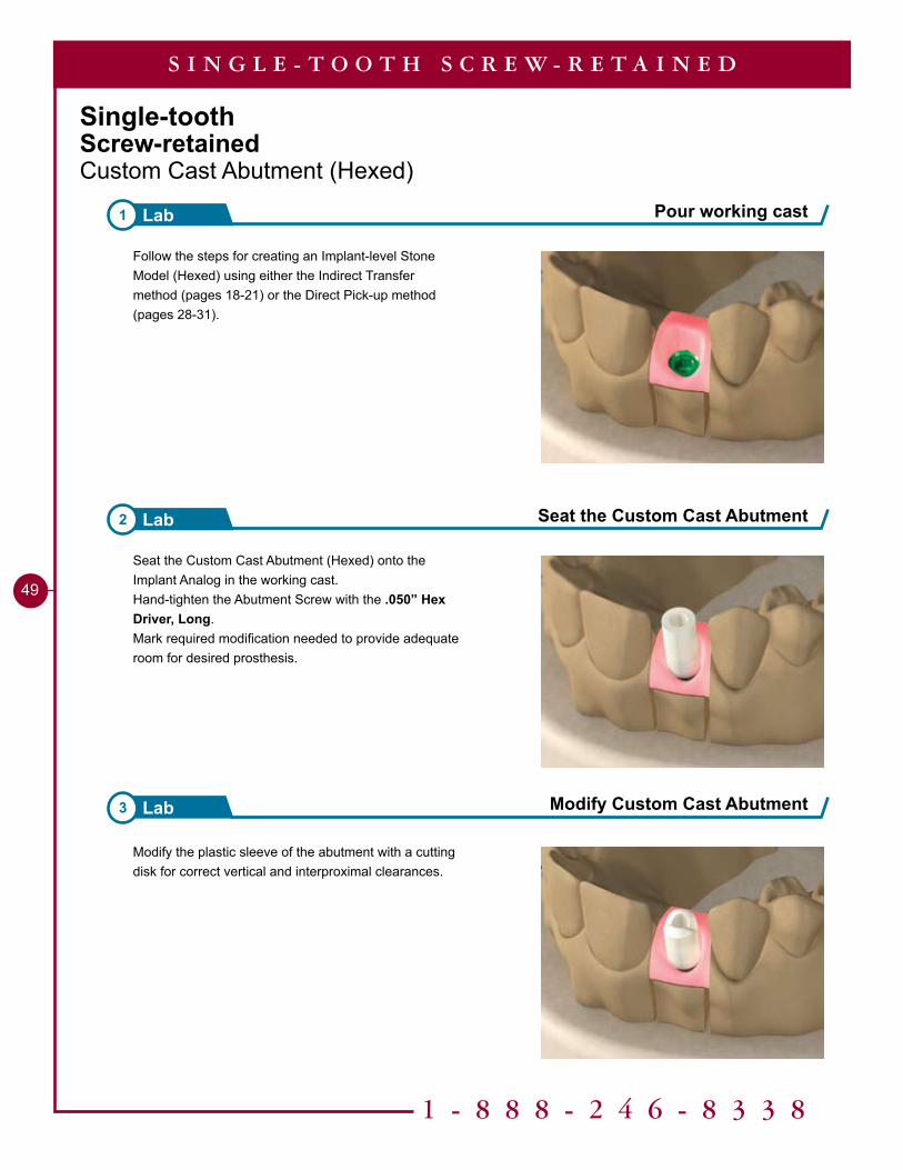
Seat the Custom Cast Abutment (Hexed) onto the Implant Analog in the working cast.Hand-tighten the Abutment Screw with the .050” Hex Driver, Long.Mark required modification needed to provide adequate room for desired prosthesis.
Modify the plastic sleeve of the abutment with a cutting disk for correct vertical and interproximal clearances.
Follow the steps for creating an Implant-level Stone Model (Hexed) using either the Indirect Transfer method (pages 18-21) or the Direct Pick-up method (pages 28-31).
50
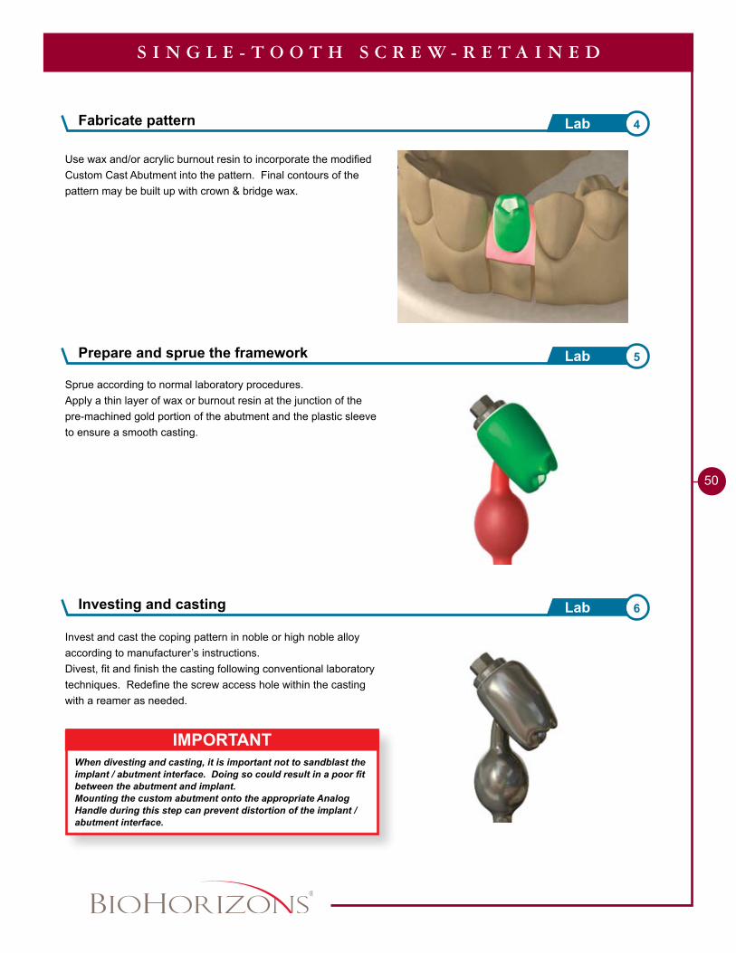
IMPORTANTWhen divesting and casting, it is important not to sandblast the implant / abutment interface. Doing so could result in a poor fit between the abutment and implant.Mounting the custom abutment onto the appropriate Analog Handle during this step can prevent distortion of the implant / abutment interface.
Fabricate pattern 4Lab
Investing and casting 6Lab
S I N G L E - T O O T H S C R E W - R E T A I N E D
Use wax and/or acrylic burnout resin to incorporate the modified Custom Cast Abutment into the pattern. Final contours of the pattern may be built up with crown & bridge wax.
Sprue according to normal laboratory procedures.Apply a thin layer of wax or burnout resin at the junction of the pre-machined gold portion of the abutment and the plastic sleeve to ensure a smooth casting.
Invest and cast the coping pattern in noble or high noble alloy according to manufacturer’s instructions.Divest, fit and finish the casting following conventional laboratory techniques. Redefine the screw access hole within the casting with a reamer as needed.
Prepare and sprue the framework 5Lab
1 - 8 8 8 - 2 4 6 - 8 3 3 8
51
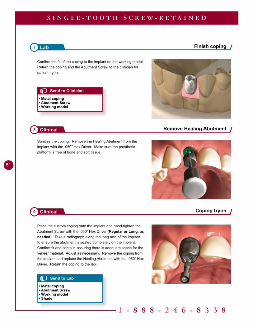
Finish coping7 Lab
Remove Healing Abutment8 Clinical
S I N G L E - T O O T H S C R E W - R E T A I N E D
Send to Clinician
• Metal coping• Abutment Screw• Working model
Send to Lab
• Metal coping• Abutment Screw• Working model• Shade
Confirm the fit of the coping to the implant on the working model. Return the coping and the Abutment Screw to the clinician for patient try-in.
Sanitize the coping. Remove the Healing Abutment from the implant with the .050” Hex Driver. Make sure the prosthetic platform is free of bone and soft tissue.
Place the custom coping onto the implant and hand-tighten the Abutment Screw with the .050” Hex Driver (Regular or Long, as needed). Take a radiograph along the long axis of the implant to ensure the abutment is seated completely on the implant. Confirm fit and contour, assuring there is adequate space for the veneer material. Adjust as necessary. Remove the coping from the implant and replace the Healing Abutment with the .050” Hex Driver. Return the coping to the lab.
Coping try-in9 Clinical
52
S I N G L E - T O O T H S C R E W - R E T A I N E D
Send to Clinician
• Final prosthesis• Abutment Screw• Working model
Finish custom crown 10Lab
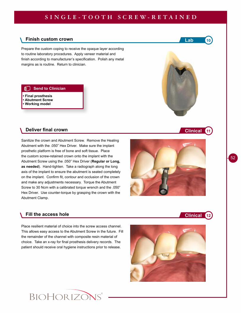
Sanitize the crown and Abutment Screw. Remove the Healing Abutment with the .050” Hex Driver. Make sure the implant prosthetic platform is free of bone and soft tissue. Place the custom screw-retained crown onto the implant with the Abutment Screw using the .050” Hex Driver (Regular or Long, as needed). Hand-tighten. Take a radiograph along the long axis of the implant to ensure the abutment is seated completely on the implant. Confirm fit, contour and occlusion of the crown and make any adjustments necessary. Torque the Abutment Screw to 30 Ncm with a calibrated torque wrench and the .050” Hex Driver. Use counter-torque by grasping the crown with the Abutment Clamp.
Prepare the custom coping to receive the opaque layer according to routine laboratory procedures. Apply veneer material and finish according to manufacturer’s specification. Polish any metal margins as is routine. Return to clinician.
Place resilient material of choice into the screw access channel. This allows easy access to the Abutment Screw in the future. Fill the remainder of the channel with composite resin material of choice. Take an x-ray for final prosthesis delivery records. The patient should receive oral hygiene instructions prior to release.
Deliver final crown 11Clinical
Fill the access hole 12Clinical
1 - 8 8 8 - 2 4 6 - 8 3 3 8
53
Tools Needed
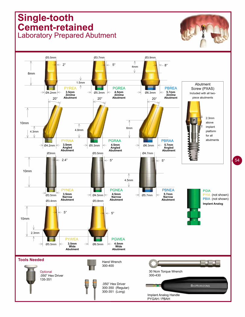
Single-toothCement-retainedLaboratory Prepared Abutment
Optional.050” Hex Driver135-351
Implant Analog HandlePYGAH / PBAH
30 Ncm Torque Wrench300-430
Hand Wrench300-400
.050” Hex Driver300-350 (Regular)300-351 (Long)
2.3mmaboveimplantplatformfor allabutments
Abutment Screw (PXAS)
Included with all two-piece abutments
P
PYREA PGREA PBREA
8mm
2° 5° 8°
Ø4.2mm Ø5.3mm Ø6.3mm
PYRAA PGRAA PBRAA
10mm
20° 20° 20°
�mm4.8mm4.3mm
Ø4.2mm Ø5.3mm Ø6.3mm
�mm
1.5mm
Ø3.5mm Ø3.7mm Ø3.9mm
PYNEA PGNEA PBNEA
10mm
2.4° 5° 5°
Ø3.5mm Ø4.5mm Ø5.7mm
4.5mm
Ø�mm Ø3.5mm Ø4.7mm
PYWEA PGWEA
10mm
5° 5°
Ø6.5mmØ5.5mm
2.3mm
Ø3.4mm Ø3.8mm
PGIAPYIA (not shown)PBIA (not shown)
3.5mm 3inOne
Abutment
4.5mm 3inOne
Abutment
5.7mm 3inOne
Abutment
3.5mm Angled
Abutment
4.5mm Angled
Abutment
5.7mm Angled
Abutment
3.5mm Narrow
Abutment
4.5mm Narrow
Abutment
5.7mm Narrow
Abutment
3.5mm Wide
Abutment
4.5mm Wide
Abutment
Implant Analog
54
1 - 8 8 8 - 2 4 6 - 8 3 3 8
55
Single-toothCement-retainedLaboratory Prepared Abutment
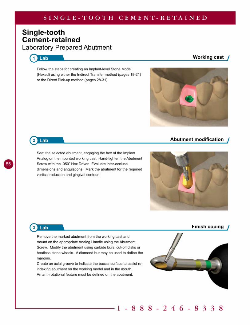
Working cast1 Lab
Abutment modification2 Lab
S I N G L E - T O O T H C E M E N T - R E T A I N E D
Seat the selected abutment, engaging the hex of the Implant Analog on the mounted working cast. Hand-tighten the Abutment Screw with the .050” Hex Driver. Evaluate inter-occlusal dimensions and angulations. Mark the abutment for the required vertical reduction and gingival contour.
Remove the marked abutment from the working cast and mount on the appropriate Analog Handle using the Abutment Screw. Modify the abutment using carbide burs, cut-off disks or heatless stone wheels. A diamond bur may be used to define the margins. Create an axial groove to indicate the buccal surface to assist re-indexing abutment on the working model and in the mouth. An anti-rotational feature must be defined on the abutment.
Finish coping3 Lab
Follow the steps for creating an Implant-level Stone Model (Hexed) using either the Indirect Transfer method (pages 18-21) or the Direct Pick-up method (pages 28-31).
56
S I N G L E - T O O T H C E M E N T - R E T A I N E D
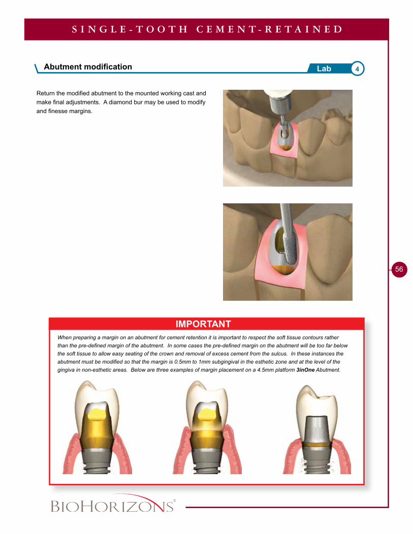
IMPORTANTWhen preparing a margin on an abutment for cement retention it is important to respect the soft tissue contours rather than the pre-defined margin of the abutment. In some cases the pre-defined margin on the abutment will be too far below the soft tissue to allow easy seating of the crown and removal of excess cement from the sulcus. In these instances the abutment must be modified so that the margin is 0.5mm to 1mm subgingival in the esthetic zone and at the level of the gingiva in non-esthetic areas. Below are three examples of margin placement on a 4.5mm platform 3inOne Abutment.
Return the modified abutment to the mounted working cast and make final adjustments. A diamond bur may be used to modify and finesse margins.
Abutment modification 4Lab
1 - 8 8 8 - 2 4 6 - 8 3 3 8
57
Finish casting7 Lab
S I N G L E - T O O T H C E M E N T - R E T A I N E D
Send to Clinician
• Metal coping• Abutment and Abutment Screw• Working model
Sprue, invest and cast6 Lab
Waxing5 Lab
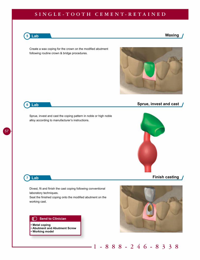
Divest, fit and finish the cast coping following conventional laboratory techniques.Seat the finished coping onto the modified abutment on the working cast.
Sprue, invest and cast the coping pattern in noble or high noble alloy according to manufacturer’s instructions.
Create a wax coping for the crown on the modified abutment following routine crown & bridge procedures.
58
S I N G L E - T O O T H C E M E N T - R E T A I N E D
Send to Lab
• Metal coping• Abutment and Abutment Screw• Working model• Shade
Send to Clinician
• Finished crown• Abutment and Abutment Screw• Working model
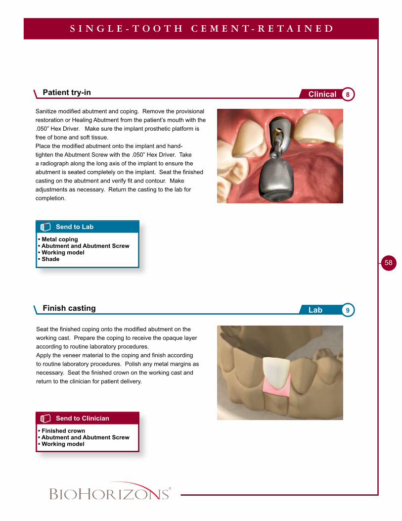
Seat the finished coping onto the modified abutment on the working cast. Prepare the coping to receive the opaque layer according to routine laboratory procedures.Apply the veneer material to the coping and finish according to routine laboratory procedures. Polish any metal margins as necessary. Seat the finished crown on the working cast and return to the clinician for patient delivery.
Sanitize modified abutment and coping. Remove the provisional restoration or Healing Abutment from the patient’s mouth with the .050” Hex Driver. Make sure the implant prosthetic platform is free of bone and soft tissue. Place the modified abutment onto the implant and hand-tighten the Abutment Screw with the .050” Hex Driver. Take a radiograph along the long axis of the implant to ensure the abutment is seated completely on the implant. Seat the finished casting on the abutment and verify fit and contour. Make adjustments as necessary. Return the casting to the lab for completion.
Finish casting 9Lab
Patient try-in 8Clinical
1 - 8 8 8 - 2 4 6 - 8 3 3 8
59
S I N G L E - T O O T H C E M E N T - R E T A I N E D
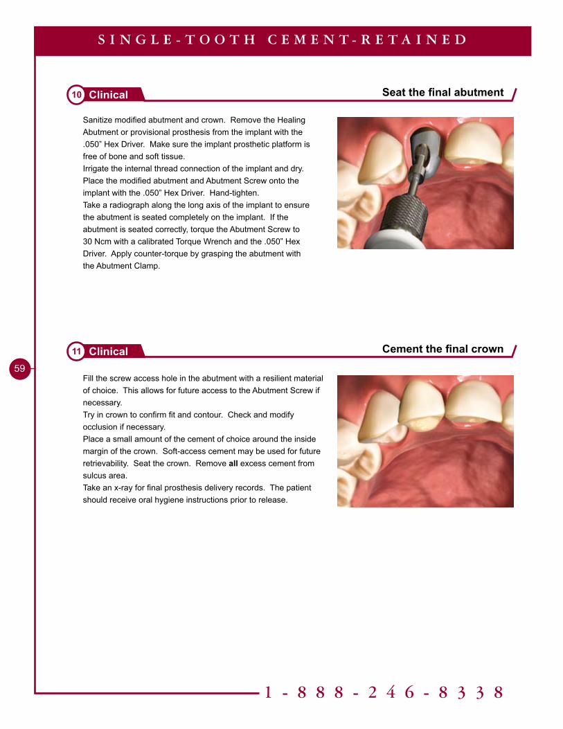
Sanitize modified abutment and crown. Remove the Healing Abutment or provisional prosthesis from the implant with the .050” Hex Driver. Make sure the implant prosthetic platform is free of bone and soft tissue.Irrigate the internal thread connection of the implant and dry.Place the modified abutment and Abutment Screw onto the implant with the .050” Hex Driver. Hand-tighten.Take a radiograph along the long axis of the implant to ensure the abutment is seated completely on the implant. If the abutment is seated correctly, torque the Abutment Screw to 30 Ncm with a calibrated Torque Wrench and the .050” Hex Driver. Apply counter-torque by grasping the abutment with the Abutment Clamp.
Fill the screw access hole in the abutment with a resilient material of choice. This allows for future access to the Abutment Screw if necessary.Try in crown to confirm fit and contour. Check and modify occlusion if necessary. Place a small amount of the cement of choice around the inside margin of the crown. Soft-access cement may be used for future retrievability. Seat the crown. Remove all excess cement from sulcus area.Take an x-ray for final prosthesis delivery records. The patient should receive oral hygiene instructions prior to release.
Seat the final abutment10 Clinical
Cement the final crown11 Clinical
Tools Needed
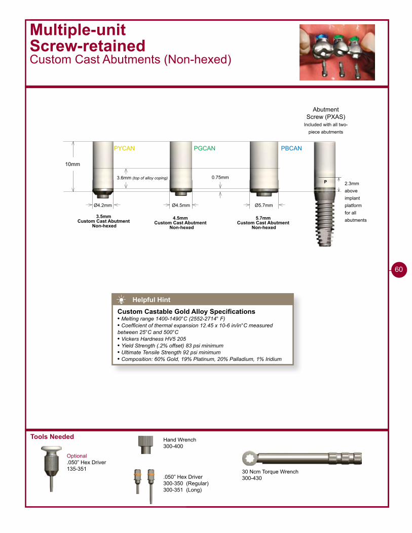
PYCAN PGCAN PBCAN
10mm
Ø4.2mm
0.75mm
Ø4.5mm Ø5.7mm
3.6mm (top of alloy coping)
3.5mmCustom Cast Abutment
Non-hexed4.5mm
Custom Cast Abutment Non-hexed
5.7mmCustom Cast Abutment
Non-hexed
Multiple-unitScrew-retainedCustom Cast Abutments (Non-hexed)
Optional.050” Hex Driver135-351
P 2.3mmaboveimplantplatformfor allabutments
Abutment Screw (PXAS)
Included with all two-piece abutments
30 Ncm Torque Wrench300-430
Hand Wrench300-400
.050” Hex Driver300-350 (Regular)300-351 (Long)
60
Helpful Hint
Custom Castable Gold Alloy Specifications• Melting range 1400-1490°C (2552-2714° F)• Coefficient of thermal expansion 12.45 x 10⁻⁶ in/in°C measured between 25°C and 500°C• Vickers Hardness HV5 205• Yield Strength (.2% offset) 83 psi minimum• Ultimate Tensile Strength 92 psi minimum• Composition: 60% Gold, 19% Platinum, 20% Palladium, 1% Iridium
1 - 8 8 8 - 2 4 6 - 8 3 3 8
��
Multiple-unitScrew-retainedCustom Cast Abutment (Non-hexed)
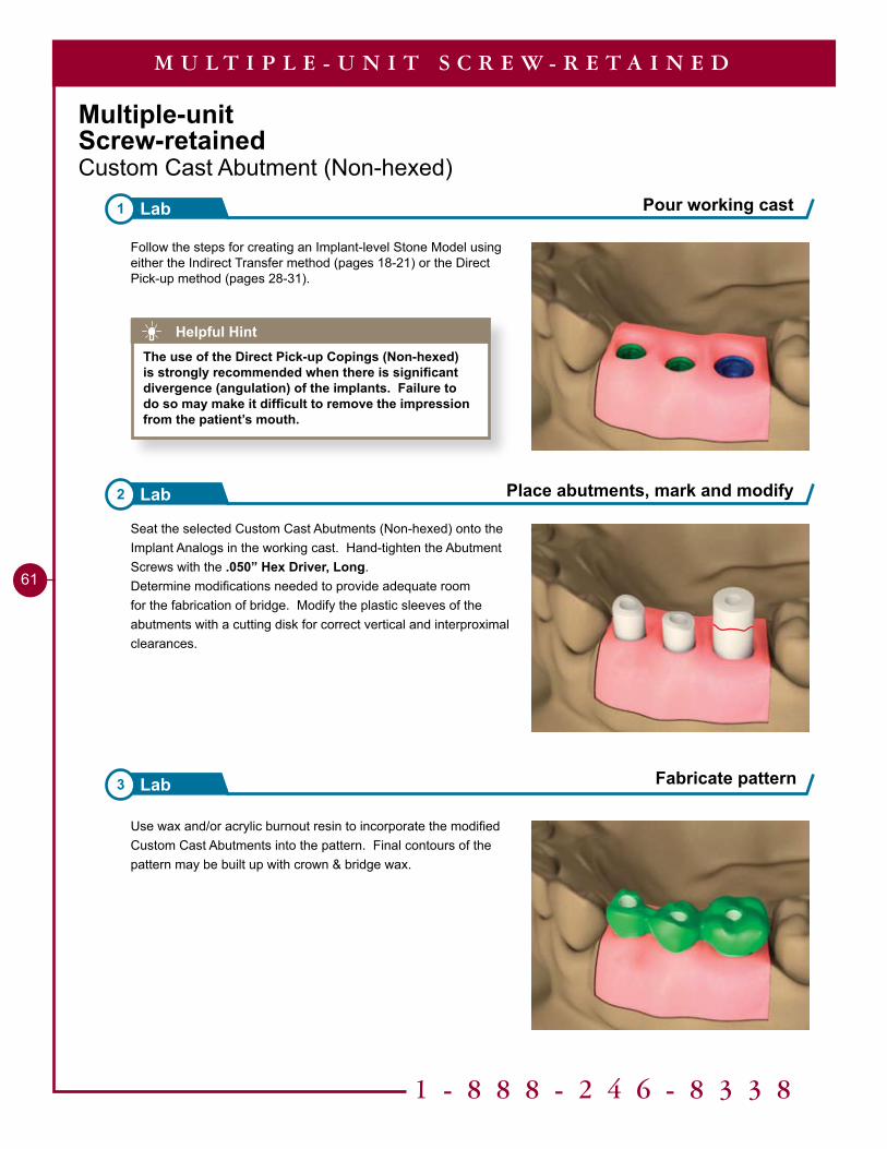
Follow the steps for creating an Implant-level Stone Model using either the Indirect Transfer method (pages 18-21) or the Direct Pick-up method (pages 28-31).
Use wax and/or acrylic burnout resin to incorporate the modified Custom Cast Abutments into the pattern. Final contours of the pattern may be built up with crown & bridge wax.
Seat the selected Custom Cast Abutments (Non-hexed) onto the Implant Analogs in the working cast. Hand-tighten the Abutment Screws with the .050” Hex Driver, Long.Determine modifications needed to provide adequate room for the fabrication of bridge. Modify the plastic sleeves of the abutments with a cutting disk for correct vertical and interproximal clearances.
Pour working cast1 Lab
Place abutments, mark and modify2 Lab
3 Lab
M U L T I P L E - U N I T S C R E W - R E T A I N E D
Helpful HintThe use of the Direct Pick-up Copings (Non-hexed) is strongly recommended when there is significant divergence (angulation) of the implants. Failure to do so may make it difficult to remove the impression from the patient’s mouth.
Fabricate pattern
�2
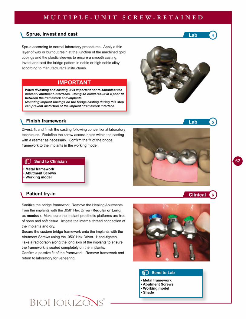
Sprue according to normal laboratory procedures. Apply a thin layer of wax or burnout resin at the junction of the machined gold copings and the plastic sleeves to ensure a smooth casting.Invest and cast the bridge pattern in noble or high noble alloy according to manufacturer’s instructions.
M U L T I P L E - U N I T S C R E W - R E T A I N E D
Send to Clinician
• Metal framework• Abutment Screws• Working model
Sanitize the bridge framework. Remove the Healing Abutments from the implants with the .050” Hex Driver (Regular or Long, as needed). Make sure the implant prosthetic platforms are free of bone and soft tissue. Irrigate the internal thread connection of the implants and dry.Secure the custom bridge framework onto the implants with the Abutment Screws using the .050” Hex Driver. Hand-tighten.Take a radiograph along the long axis of the implants to ensure the framework is seated completely on the implants.Confirm a passive fit of the framework. Remove framework and return to laboratory for veneering.
Send to Lab
• Metal framework• Abutment Screws• Working model• Shade
Divest, fit and finish the casting following conventional laboratory techniques. Redefine the screw access holes within the casting with a reamer as necessary. Confirm the fit of the bridge framework to the implants in the working model.
IMPORTANTWhen divesting and casting, it is important not to sandblast the implant / abutment interfaces. Doing so could result in a poor fit between the framework and implants.Mounting Implant Analogs on the bridge casting during this step can prevent distortion of the implant / framework interface.
Sprue, invest and cast 4Lab
Finish framework 5Lab
Patient try-in 6Clinical
1 - 8 8 8 - 2 4 6 - 8 3 3 8
��
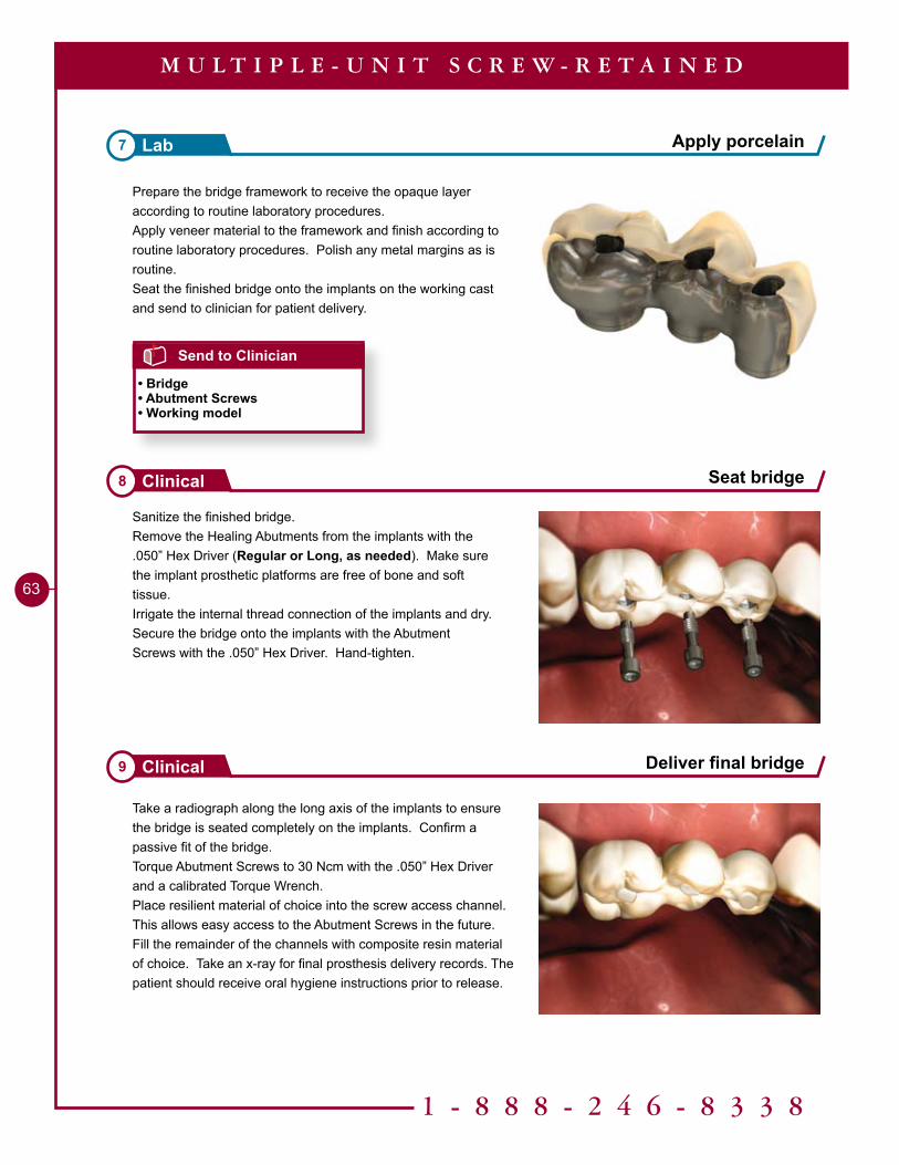
Prepare the bridge framework to receive the opaque layer according to routine laboratory procedures.Apply veneer material to the framework and finish according to routine laboratory procedures. Polish any metal margins as is routine. Seat the finished bridge onto the implants on the working cast and send to clinician for patient delivery.
Sanitize the finished bridge.Remove the Healing Abutments from the implants with the .050” Hex Driver (Regular or Long, as needed). Make sure the implant prosthetic platforms are free of bone and soft tissue.Irrigate the internal thread connection of the implants and dry.Secure the bridge onto the implants with the Abutment Screws with the .050” Hex Driver. Hand-tighten.
Take a radiograph along the long axis of the implants to ensure the bridge is seated completely on the implants. Confirm a passive fit of the bridge.Torque Abutment Screws to 30 Ncm with the .050” Hex Driver and a calibrated Torque Wrench.Place resilient material of choice into the screw access channel. This allows easy access to the Abutment Screws in the future. Fill the remainder of the channels with composite resin material of choice. Take an x-ray for final prosthesis delivery records. The patient should receive oral hygiene instructions prior to release.
Apply porcelain7 Lab
Seat bridge8 Clinical
Deliver final bridge9 Clinical
M U L T I P L E - U N I T S C R E W - R E T A I N E D
Send to Clinician
• Bridge• Abutment Screws• Working model
Tools Needed
Multiple-unitCement-retained Laboratory Prepared Abutments
Optional.050” Hex Driver135-351
Implant Analog HandlePYGAH / PBAH
30 Ncm Torque Wrench300-430
Hand Wrench300-400
.050” Hex Driver300-350 (Regular)300-351 (Long)
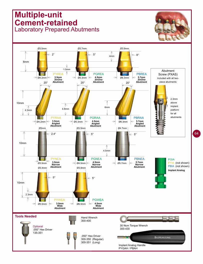
2.3mmaboveimplantplatformfor allabutments
Abutment Screw (PXAS)
Included with all two-piece abutments
P
PYREA PGREA PBREA
8mm
2° 5° 8°
Ø4.2mm Ø5.3mm Ø6.3mm
PYRAA PGRAA PBRAA
10mm
20° 20° 20°
�mm4.8mm4.3mm
Ø4.2mm Ø5.3mm Ø6.3mm
�mm
1.5mm
Ø3.5mm Ø3.7mm Ø3.9mm
PYNEA PGNEA PBNEA
10mm
2.4° 5° 5°
Ø3.5mm Ø4.5mm Ø5.7mm
4.5mm
Ø�mm Ø3.5mm Ø4.7mm
PYWEA PGWEA
10mm
5° 5°
Ø6.5mmØ5.5mm
2.3mm
Ø3.4mm Ø3.8mm
PGIAPYIA (not shown)PBIA (not shown)
3.5mm 3inOne
Abutment
4.5mm 3inOne
Abutment
5.7mm 3inOne
Abutment
3.5mm Angled
Abutment
4.5mm Angled
Abutment
5.7mm Angled
Abutment
3.5mm Narrow
Abutment
4.5mm Narrow
Abutment
5.7mm Narrow
Abutment
3.5mm Wide
Abutment
4.5mm Wide
Abutment
Implant Analog
��
Multiple-unitCement-retainedLaboratory Prepared Abutments
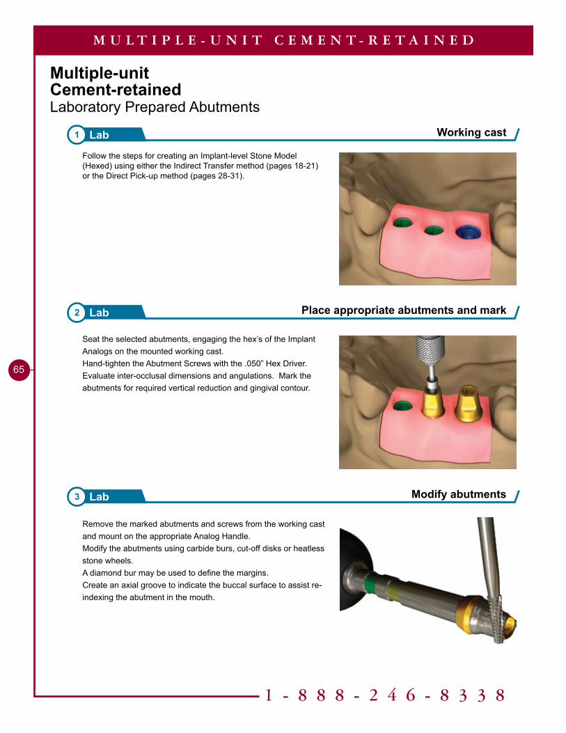
Follow the steps for creating an Implant-level Stone Model (Hexed) using either the Indirect Transfer method (pages 18-21) or the Direct Pick-up method (pages 28-31).
Seat the selected abutments, engaging the hex’s of the Implant Analogs on the mounted working cast. Hand-tighten the Abutment Screws with the .050” Hex Driver. Evaluate inter-occlusal dimensions and angulations. Mark the abutments for required vertical reduction and gingival contour.
Remove the marked abutments and screws from the working cast and mount on the appropriate Analog Handle. Modify the abutments using carbide burs, cut-off disks or heatless stone wheels. A diamond bur may be used to define the margins. Create an axial groove to indicate the buccal surface to assist re-indexing the abutment in the mouth.
Modify abutments3 Lab
1 - 8 8 8 - 2 4 6 - 8 3 3 8
65
Working cast1 Lab
Place appropriate abutments and mark2 Lab
M U L T I P L E - U N I T C E M E N T - R E T A I N E D
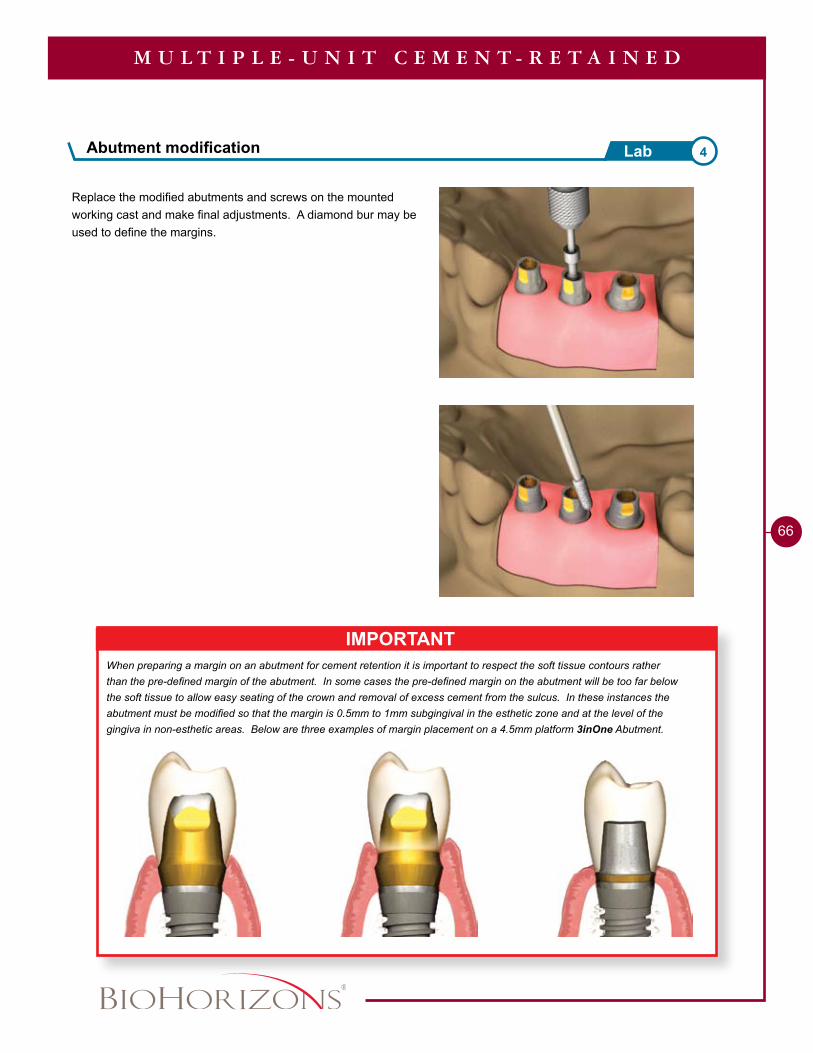
Replace the modified abutments and screws on the mounted working cast and make final adjustments. A diamond bur may be used to define the margins.
��
M U L T I P L E - U N I T C E M E N T - R E T A I N E D
IMPORTANTWhen preparing a margin on an abutment for cement retention it is important to respect the soft tissue contours rather than the pre-defined margin of the abutment. In some cases the pre-defined margin on the abutment will be too far below the soft tissue to allow easy seating of the crown and removal of excess cement from the sulcus. In these instances the abutment must be modified so that the margin is 0.5mm to 1mm subgingival in the esthetic zone and at the level of the gingiva in non-esthetic areas. Below are three examples of margin placement on a 4.5mm platform 3inOne Abutment.
Abutment modification 4Lab
Divest, fit and finish the cast framework following conventional laboratory techniques.Care should be taken to insure a passive fit of the framework on the modified abutments. Send the working cast, the modified abutments and the framework to the clinician for a metal framework try-in. The dentist should confirm the passive fit of the framework prior to the application of the veneering material.
7 Lab Finish casting
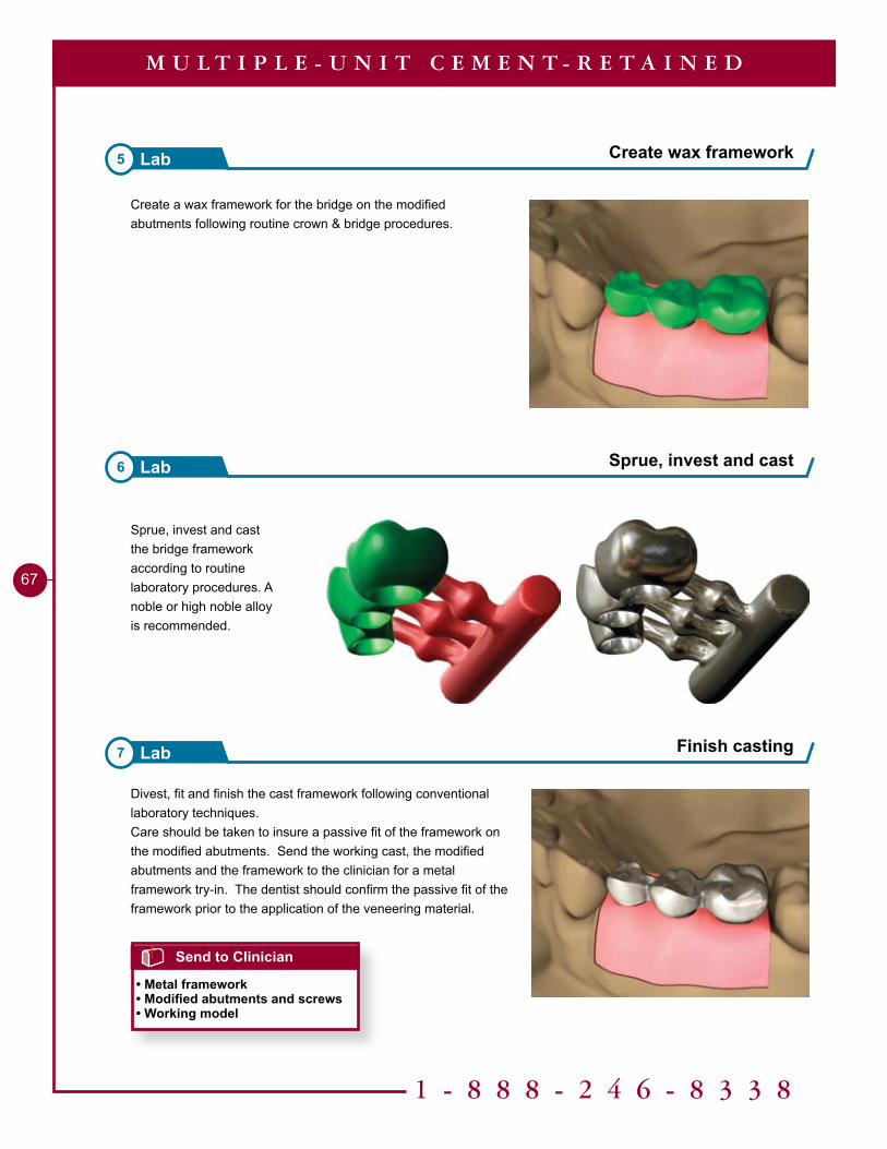
Create a wax framework for the bridge on the modified abutments following routine crown & bridge procedures.
Sprue, invest and cast the bridge framework according to routine laboratory procedures. A noble or high noble alloy is recommended.
5 Lab Create wax framework
6 Lab Sprue, invest and cast
1 - 8 8 8 - 2 4 6 - 8 3 3 8
67
M U L T I P L E - U N I T C E M E N T - R E T A I N E D
Send to Clinician
• Metal framework• Modified abutments and screws• Working model

Seat the finished framework onto the modified abutments on the working cast.Prepare the framework to receive the opaque layer according to routine laboratory procedures.Veneer material is applied to the framework and finished according to routine laboratory procedures. Polish any metal margins as is routine. Seat the finished bridge on the prepared abutments on the working cast and send to clinician for patient delivery.
Sanitize the modified abutments and the bridge framework. Remove the Healing Abutments from the implants with the .050” Hex Driver. Make sure the implant prosthetic platforms are free of bone and soft tissue. Irrigate the internal thread connection of the implant and dry.Place the modified abutments and Abutment Screws onto the implants with the .050” Hex Driver. Hand-tighten. Take a radiograph along the long axis of the implants to ensure the abutments are seated completely on the implants.Try in bridge framework. Confirm passive fit and that no additional adjustments are necessary. Remove bridge framework. Remove the modified abutments with the .050” Hex Driver, one at a time, replacing them with the Healing Abutments.
Finish casting 9Lab
68
Send to Clinician
• Finished prosthesis• Modified abutments and screws• Working model
M U L T I P L E - U N I T C E M E N T - R E T A I N E D
Send to Lab
• Metal framework• Modified abutments and screws• Working model• Shade
Try in modified abutments and framework 8Clinical
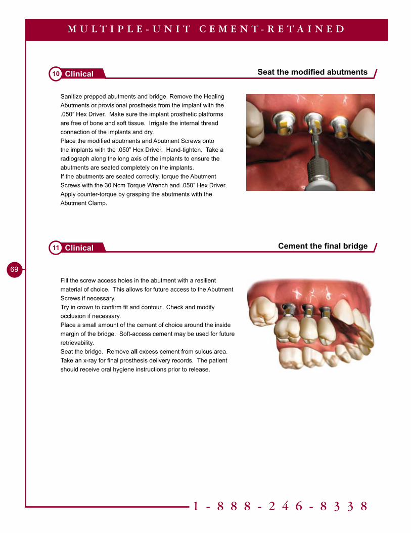
Sanitize prepped abutments and bridge. Remove the Healing Abutments or provisional prosthesis from the implant with the .050” Hex Driver. Make sure the implant prosthetic platforms are free of bone and soft tissue. Irrigate the internal thread connection of the implants and dry.Place the modified abutments and Abutment Screws onto the implants with the .050” Hex Driver. Hand-tighten. Take a radiograph along the long axis of the implants to ensure the abutments are seated completely on the implants.If the abutments are seated correctly, torque the Abutment Screws with the 30 Ncm Torque Wrench and .050” Hex Driver. Apply counter-torque by grasping the abutments with the Abutment Clamp.
Fill the screw access holes in the abutment with a resilient material of choice. This allows for future access to the Abutment Screws if necessary.Try in crown to confirm fit and contour. Check and modify occlusion if necessary. Place a small amount of the cement of choice around the inside margin of the bridge. Soft-access cement may be used for future retrievability.Seat the bridge. Remove all excess cement from sulcus area.Take an x-ray for final prosthesis delivery records. The patient should receive oral hygiene instructions prior to release.
1 - 8 8 8 - 2 4 6 - 8 3 3 8
�9
Seat the modified abutments10 Clinical
Cement the final bridge11 Clinical
M U L T I P L E - U N I T C E M E N T - R E T A I N E D

Tools Needed
Insert Seating ToolBCIST
ReamerBCR
Ball AbutmentOverdentureExisting Denture, Chairside Pick-up
30 Ncm Torque Wrench300-430
Hand Wrench300-400
.050” Hex Driver300-350 regular
Ball Attachment Set
Ø6.3mmØ5.0mm
5mm2.7mm
3.2mmBCAS 260-100
O-Ring Attachment Set
Attachment Housing
Directional Rings0°, 7° and 14°
Clinical Nylon Inserts
O-Ring Encapsulator
Clinical O-Ring
Processing O-RingPositioning Nylon Insert
Standard (firmest)SoftElastic Extra Soft
Relative Retention
70
Two attachment options are available for securing dentures with Ball Abutments: the Ball Attachment System and the O-ring Attachment System. The Ball Attachment System offers the advantages of a greater degree of angulation correction and multiple options for insert retention. The O-Ring Attachment System offers a lower profile for cases with limited vertical height.
The case demonstrated in this section shows the Ball Attachment System. For procedures with the O-Ring Attachment system follow the same procedure, substituting the Encapsulators for the Attachment Housings and the O-Rings for the Nylon Inserts.
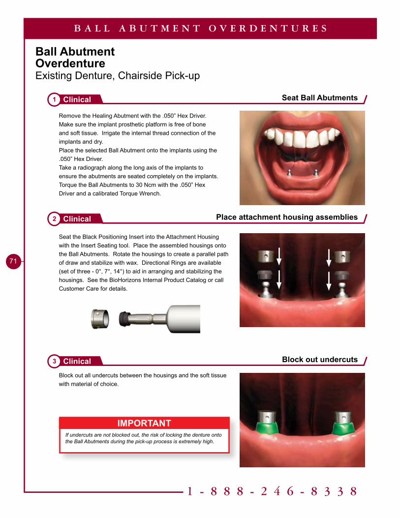
1 - 8 8 8 - 2 4 6 - 8 3 3 8
71
Ball AbutmentOverdentureExisting Denture, Chairside Pick-up
Remove the Healing Abutment with the .050” Hex Driver. Make sure the implant prosthetic platform is free of bone and soft tissue. Irrigate the internal thread connection of the implants and dry.Place the selected Ball Abutment onto the implants using the .050” Hex Driver.Take a radiograph along the long axis of the implants to ensure the abutments are seated completely on the implants.Torque the Ball Abutments to 30 Ncm with the .050” Hex Driver and a calibrated Torque Wrench.
Seat the Black Positioning Insert into the Attachment Housing with the Insert Seating tool. Place the assembled housings onto the Ball Abutments. Rotate the housings to create a parallel path of draw and stabilize with wax. Directional Rings are available (set of three - 0°, 7°, 14°) to aid in arranging and stabilizing the housings. See the BioHorizons Internal Product Catalog or call Customer Care for details.
Block out all undercuts between the housings and the soft tissue with material of choice.
Seat Ball Abutments1 Clinical
Place attachment housing assemblies2 Clinical
Block out undercuts3 Clinical
B A L L A B U T M E N T O V E R D E N T U R E S
IMPORTANTIf undercuts are not blocked out, the risk of locking the denture onto the Ball Abutments during the pick-up process is extremely high.
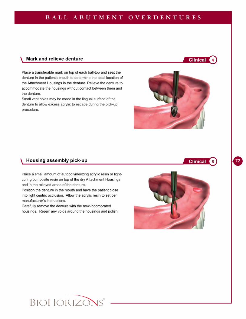
72
Place a transferable mark on top of each ball-top and seat the denture in the patient’s mouth to determine the ideal location of the Attachment Housings in the denture. Relieve the denture to accommodate the housings without contact between them and the denture.Small vent holes may be made in the lingual surface of the denture to allow excess acrylic to escape during the pick-up procedure.
Place a small amount of autopolymerizing acrylic resin or light-curing composite resin on top of the dry Attachment Housings and in the relieved areas of the denture.Position the denture in the mouth and have the patient close into light centric occlusion. Allow the acrylic resin to set per manufacturer’s instructions.Carefully remove the denture with the now-incorporated housings. Repair any voids around the housings and polish.
B A L L A B U T M E N T O V E R D E N T U R E S
Mark and relieve denture 4Clinical
Housing assembly pick-up 5Clinical
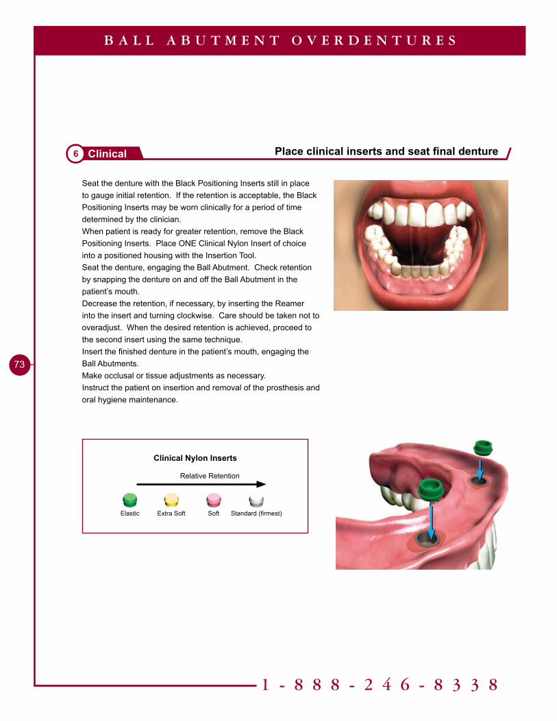
Standard (firmest)SoftElastic Extra Soft
Relative Retention
Clinical Nylon Inserts
1 - 8 8 8 - 2 4 6 - 8 3 3 8
73
Place clinical inserts and seat final denture6 Clinical
B A L L A B U T M E N T O V E R D E N T U R E S
Seat the denture with the Black Positioning Inserts still in place to gauge initial retention. If the retention is acceptable, the Black Positioning Inserts may be worn clinically for a period of time determined by the clinician.When patient is ready for greater retention, remove the Black Positioning Inserts. Place ONE Clinical Nylon Insert of choice into a positioned housing with the Insertion Tool.Seat the denture, engaging the Ball Abutment. Check retention by snapping the denture on and off the Ball Abutment in the patient’s mouth.Decrease the retention, if necessary, by inserting the Reamer into the insert and turning clockwise. Care should be taken not to overadjust. When the desired retention is achieved, proceed to the second insert using the same technique.Insert the finished denture in the patient’s mouth, engaging the Ball Abutments.Make occlusal or tissue adjustments as necessary.Instruct the patient on insertion and removal of the prosthesis and oral hygiene maintenance.
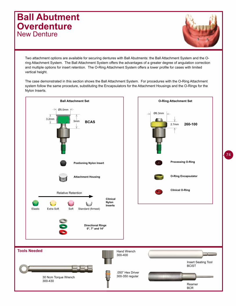
Tools Needed
Ball AbutmentOverdentureNew Denture
Two attachment options are available for securing dentures with Ball Abutments: the Ball Attachment System and the O-ring Attachment System. The Ball Attachment System offers the advantages of a greater degree of angulation correction and multiple options for insert retention. The O-Ring Attachment System offers a lower profile for cases with limited vertical height.
The case demonstrated in this section shows the Ball Attachment System. For procedures with the O-Ring Attachment system follow the same procedure, substituting the Encapsulators for the Attachment Housings and the O-Rings for the Nylon Inserts.
Insert Seating ToolBCIST
ReamerBCR
30 Ncm Torque Wrench300-430
Hand Wrench300-400
.050” Hex Driver300-350 regular
Ball Attachment Set
Ø6.3mmØ5.0mm
5mm2.7mm
3.2mmBCAS 260-100
O-Ring Attachment Set
Attachment Housing
Directional Rings0°, 7° and 14°
Clinical Nylon Inserts
O-Ring Encapsulator
Clinical O-Ring
Processing O-RingPostioning Nylon Insert
Standard (firmest)SoftElastic Extra Soft
Relative Retention
74
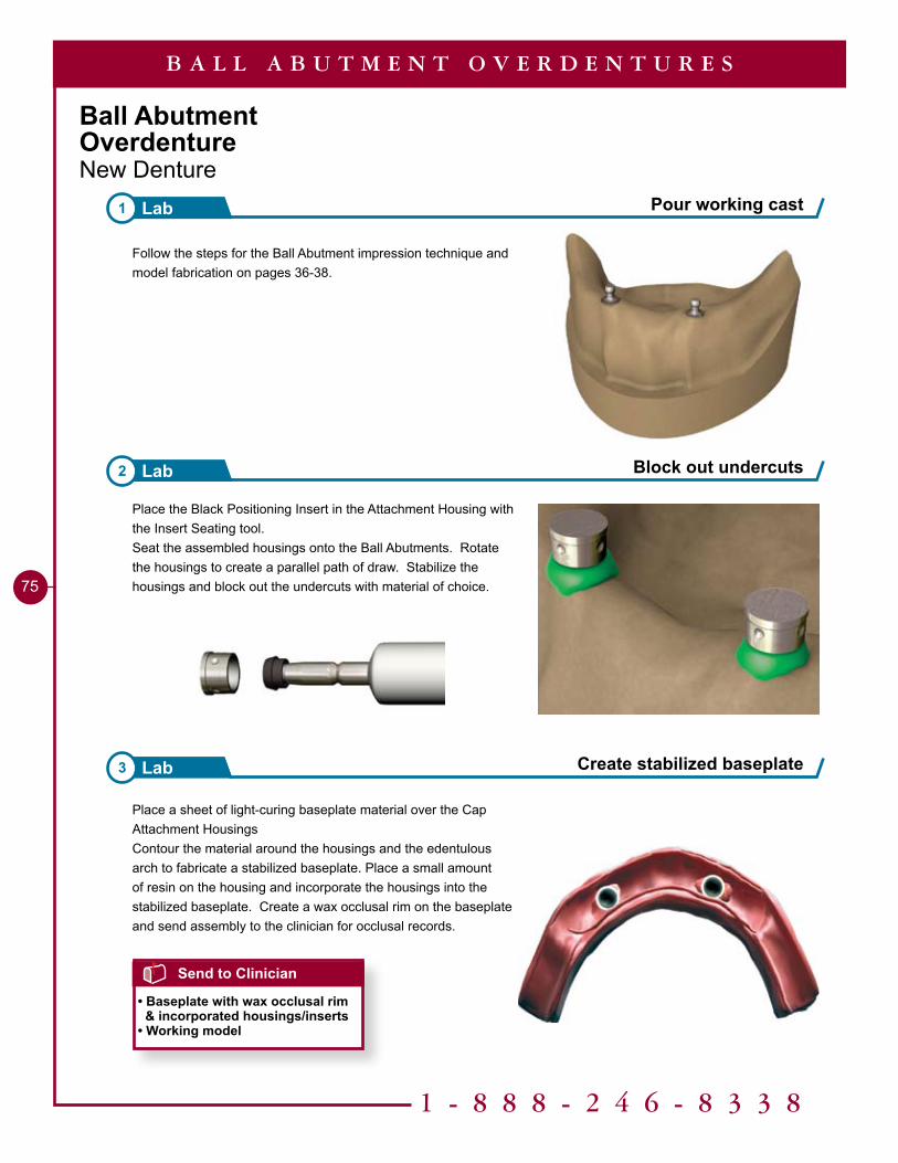
Pour working cast1 Lab
Block out undercuts2 Lab
1 - 8 8 8 - 2 4 6 - 8 3 3 8
75
Ball AbutmentOverdentureNew Denture
Follow the steps for the Ball Abutment impression technique and model fabrication on pages 36-38.
Place the Black Positioning Insert in the Attachment Housing with the Insert Seating tool.Seat the assembled housings onto the Ball Abutments. Rotate the housings to create a parallel path of draw. Stabilize the housings and block out the undercuts with material of choice.
Place a sheet of light-curing baseplate material over the Cap Attachment HousingsContour the material around the housings and the edentulous arch to fabricate a stabilized baseplate. Place a small amount of resin on the housing and incorporate the housings into the stabilized baseplate. Create a wax occlusal rim on the baseplate and send assembly to the clinician for occlusal records.
Create stabilized baseplate3 Lab
B A L L A B U T M E N T O V E R D E N T U R E S
Send to Clinician
• Baseplate with wax occlusal rim & incorporated housings/inserts• Working model
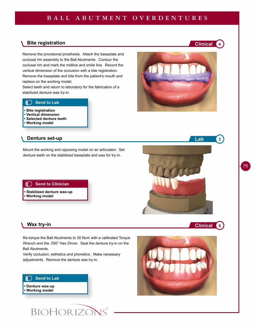
76
Remove the provisional prosthesis. Attach the baseplate and occlusal rim assembly to the Ball Abutments. Contour the occlusal rim and mark the midline and smile line. Record the vertical dimension of the occlusion with a bite registration.Remove the baseplate and bite from the patient’s mouth and replace on the working model. Select teeth and return to laboratory for the fabrication of a stabilized denture wax try-in.
Mount the working and opposing model on an articulator. Set denture teeth on the stabilized baseplate and wax for try-in.
B A L L A B U T M E N T O V E R D E N T U R E S
Send to Lab
• Bite registration• Vertical dimension• Selected denture teeth• Working model
Send to Clinician
• Stabilized denture wax-up• Working model
Re-torque the Ball Abutments to 30 Ncm with a calibrated Torque Wrench and the .050” Hex Driver. Seat the denture try-in on the Ball Abutments.Verify occlusion, esthetics and phonetics. Make necessary adjustments. Remove the denture wax try-in.
Send to Lab
• Denture wax-up• Working model
Bite registration 4Clinical
Denture set-up 5Lab
Wax try-in 6Clinical
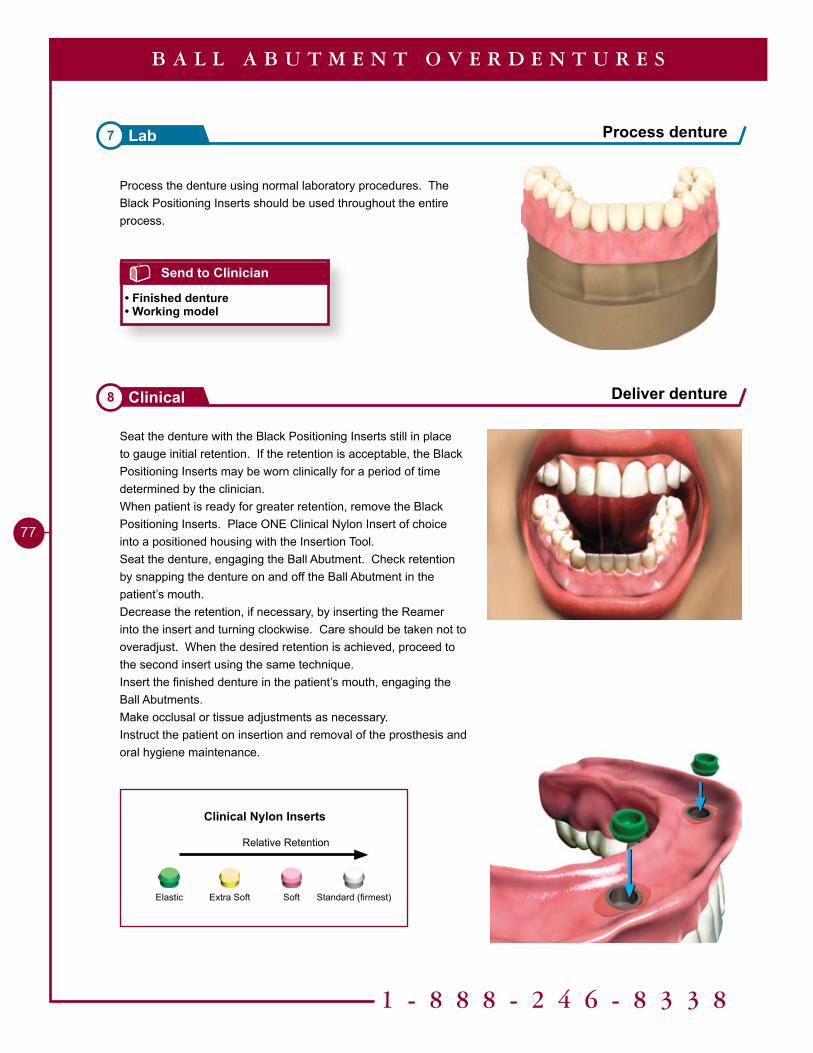
Deliver denture8 Clinical
Standard (firmest)SoftElastic Extra Soft
Relative Retention
Clinical Nylon Inserts
1 - 8 8 8 - 2 4 6 - 8 3 3 8
77
Process the denture using normal laboratory procedures. The Black Positioning Inserts should be used throughout the entire process.
Seat the denture with the Black Positioning Inserts still in place to gauge initial retention. If the retention is acceptable, the Black Positioning Inserts may be worn clinically for a period of time determined by the clinician.When patient is ready for greater retention, remove the Black Positioning Inserts. Place ONE Clinical Nylon Insert of choice into a positioned housing with the Insertion Tool.Seat the denture, engaging the Ball Abutment. Check retention by snapping the denture on and off the Ball Abutment in the patient’s mouth.Decrease the retention, if necessary, by inserting the Reamer into the insert and turning clockwise. Care should be taken not to overadjust. When the desired retention is achieved, proceed to the second insert using the same technique.Insert the finished denture in the patient’s mouth, engaging the Ball Abutments.Make occlusal or tissue adjustments as necessary.Instruct the patient on insertion and removal of the prosthesis and oral hygiene maintenance.
Process denture7 Lab
B A L L A B U T M E N T O V E R D E N T U R E S
Send to Clinician
• Finished denture• Working model
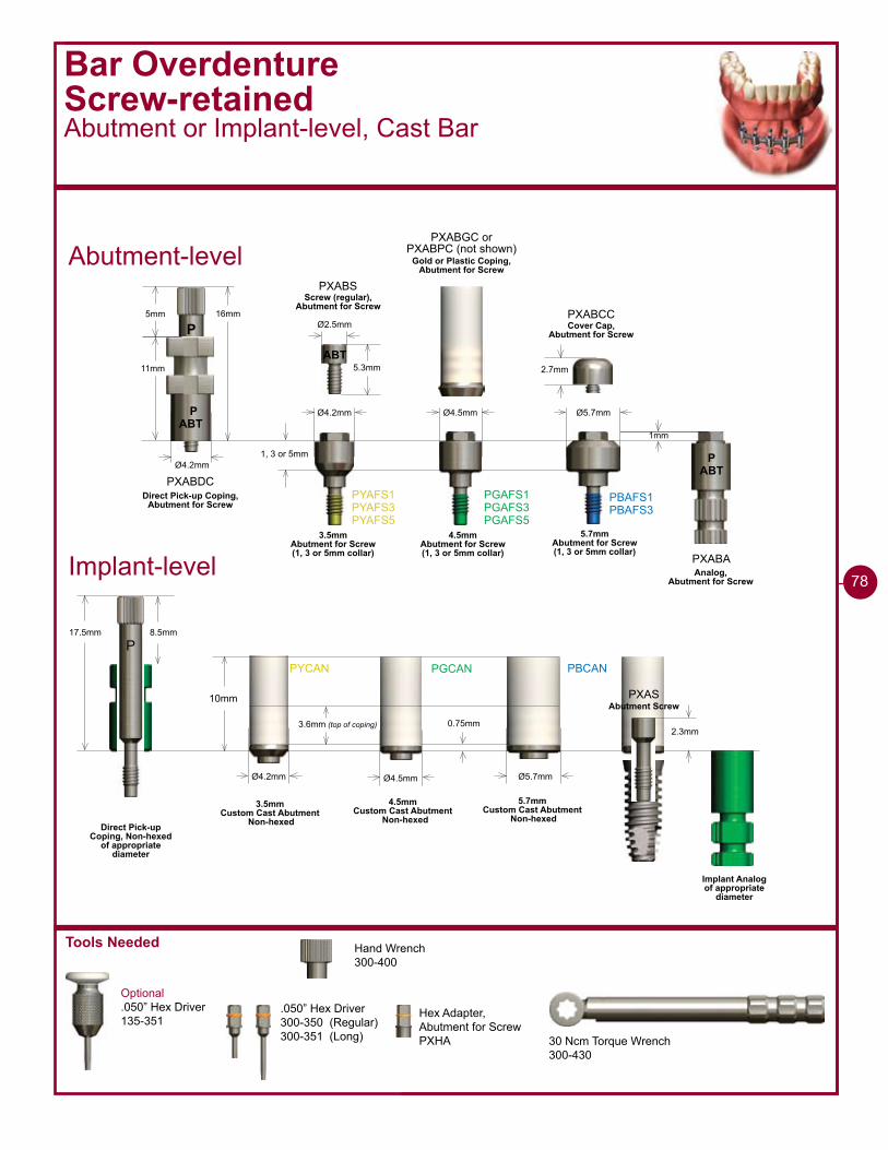
Tools Needed
30 Ncm Torque Wrench300-430
Bar OverdentureScrew-retainedAbutment or Implant-level, Cast Bar
2.7mm
ABTP
Ø4.2mm
��mm
��mm
PXABDC
P5mm
ABT5.3mm
Ø2.5mm
PXABS
Ø4.2mm Ø4.5mm Ø5.7mm
�mm
1, 3 or 5mm
PYAFS�PYAFS�PYAFS5
PGAFS�PGAFS�PGAFS5
PBAFS�PBAFS�
PXABA
PXABCC
ABTP
3.5mmAbutment for Screw (1, 3 or 5mm collar)
4.5mmAbutment for Screw (1, 3 or 5mm collar)
5.7mmAbutment for Screw (1, 3 or 5mm collar)
Direct Pick-up Coping,Abutment for Screw
Screw (regular),Abutment for Screw
Analog,Abutment for Screw
Cover Cap,Abutment for Screw
PYCAN PGCAN PBCAN
10mm
Ø4.2mm
0.75mm
Ø4.5mm Ø5.7mm
3.6mm (top of coping)
3.5mmCustom Cast Abutment
Non-hexed
4.5mmCustom Cast Abutment
Non-hexed
5.7mmCustom Cast Abutment
Non-hexed
17.5mm 8.5mm
P
Implant Analogof appropriate
diameter
Direct Pick-up Coping, Non-hexed
of appropriate diameter
Abutment-level
Implant-level
PXABGC orPXABPC (not shown)
Gold or Plastic Coping,Abutment for Screw
2.3mm
PXASAbutment Screw
Optional.050” Hex Driver135-351
Hand Wrench300-400
.050” Hex Driver300-350 (Regular)300-351 (Long)
78
Hex Adapter,Abutment for ScrewPXHA
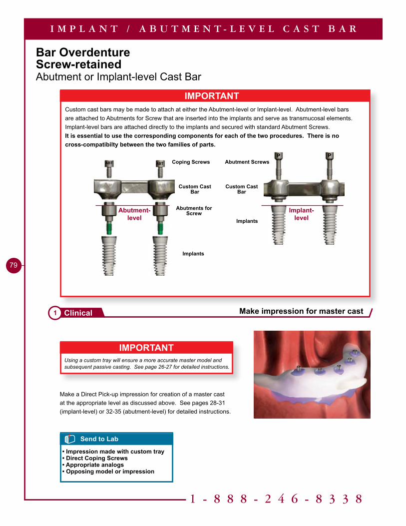
1 - 8 8 8 - 2 4 6 - 8 3 3 8
79
Bar OverdentureScrew-retainedAbutment or Implant-level Cast Bar
IMPORTANTUsing a custom tray will ensure a more accurate master model and subsequent passive casting. See page 26-27 for detailed instructions.
I M P L A N T / A B U T M E N T - L E V E L C A S T B A R
Make a Direct Pick-up impression for creation of a master cast at the appropriate level as discussed above. See pages 28-31 (implant-level) or 32-35 (abutment-level) for detailed instructions.
Send to Lab
• Impression made with custom tray• Direct Coping Screws• Appropriate analogs• Opposing model or impression
Make impression for master cast1 Clinical
IMPORTANTCustom cast bars may be made to attach at either the Abutment-level or Implant-level. Abutment-level bars are attached to Abutments for Screw that are inserted into the implants and serve as transmucosal elements. Implant-level bars are attached directly to the implants and secured with standard Abutment Screws.It is essential to use the corresponding components for each of the two procedures. There is no cross-compatibilty between the two families of parts.
ABT ABT
Custom Cast Bar
Coping Screws
Implants
Abutments for Screw
P P
Custom Cast Bar
Abutment Screws
Implants
Abutment-level
Implant-level

Fabricating a stabilized baseplate / occlusal rim / verification jig 2Lab
80
Helpful Hint
Do not extend the acrylic base to the bottom of the coping. Keep clearance between 2-3mm from the bottom of the coping.
Place a sheet of light-curing baseplate material around the direct pick-up copings. Contour the material around the copings and posterior along the edentulous arch. This will be used to stabilized the wax rim later. Light-cure the material.
Send to Clinician
• Base plate/occlusal rim mounted on master cast
I M P L A N T / A B U T M E N T - L E V E L C A S T B A R
Assemble the appropriate diameter analog to the Direct Pick-up Coping with the coping screw. Pour stone model following conventional laboratory techniques.
Place the direct pick-up copings on the model with the long coping screws.
Create a wax occlusal rim on the stabilized baseplate with ridges to allow access to the screws. Only two screws in the first cuspid areas are needed to secure the assembly to the model.Index the occlusal rim to stabilize bite registration material used in next step.
ABTP
2-�mm
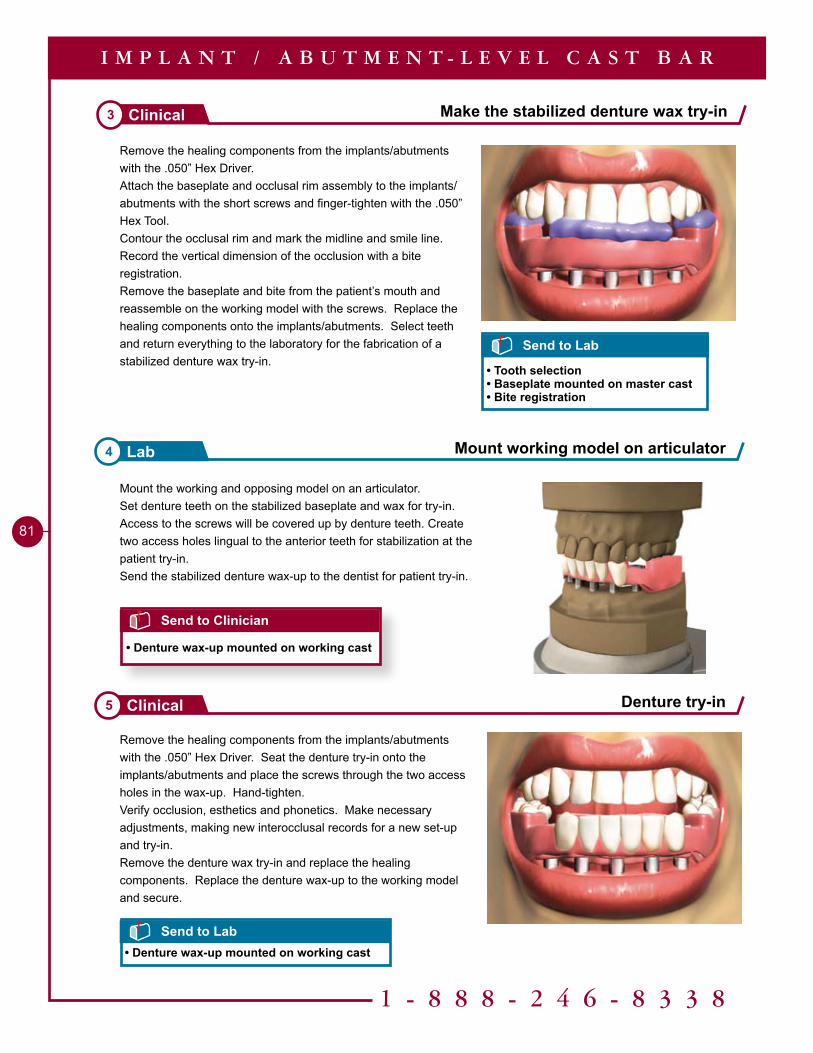
1 - 8 8 8 - 2 4 6 - 8 3 3 8
81
Mount the working and opposing model on an articulator.Set denture teeth on the stabilized baseplate and wax for try-in. Access to the screws will be covered up by denture teeth. Create two access holes lingual to the anterior teeth for stabilization at the patient try-in.Send the stabilized denture wax-up to the dentist for patient try-in.
Remove the healing components from the implants/abutments with the .050” Hex Driver. Seat the denture try-in onto the implants/abutments and place the screws through the two access holes in the wax-up. Hand-tighten.Verify occlusion, esthetics and phonetics. Make necessary adjustments, making new interocclusal records for a new set-up and try-in.Remove the denture wax try-in and replace the healing components. Replace the denture wax-up to the working model and secure.
Remove the healing components from the implants/abutments with the .050” Hex Driver. Attach the baseplate and occlusal rim assembly to the implants/abutments with the short screws and finger-tighten with the .050” Hex Tool.Contour the occlusal rim and mark the midline and smile line. Record the vertical dimension of the occlusion with a bite registration.Remove the baseplate and bite from the patient’s mouth and reassemble on the working model with the screws. Replace the healing components onto the implants/abutments. Select teeth and return everything to the laboratory for the fabrication of a stabilized denture wax try-in.
Make the stabilized denture wax try-in3 Clinical
Denture try-in5 Clinical
Mount working model on articulator4 Lab
I M P L A N T / A B U T M E N T - L E V E L C A S T B A R
Send to Clinician
• Denture wax-up mounted on working cast
Send to Lab
• Tooth selection• Baseplate mounted on master cast• Bite registration
Send to Lab• Denture wax-up mounted on working cast
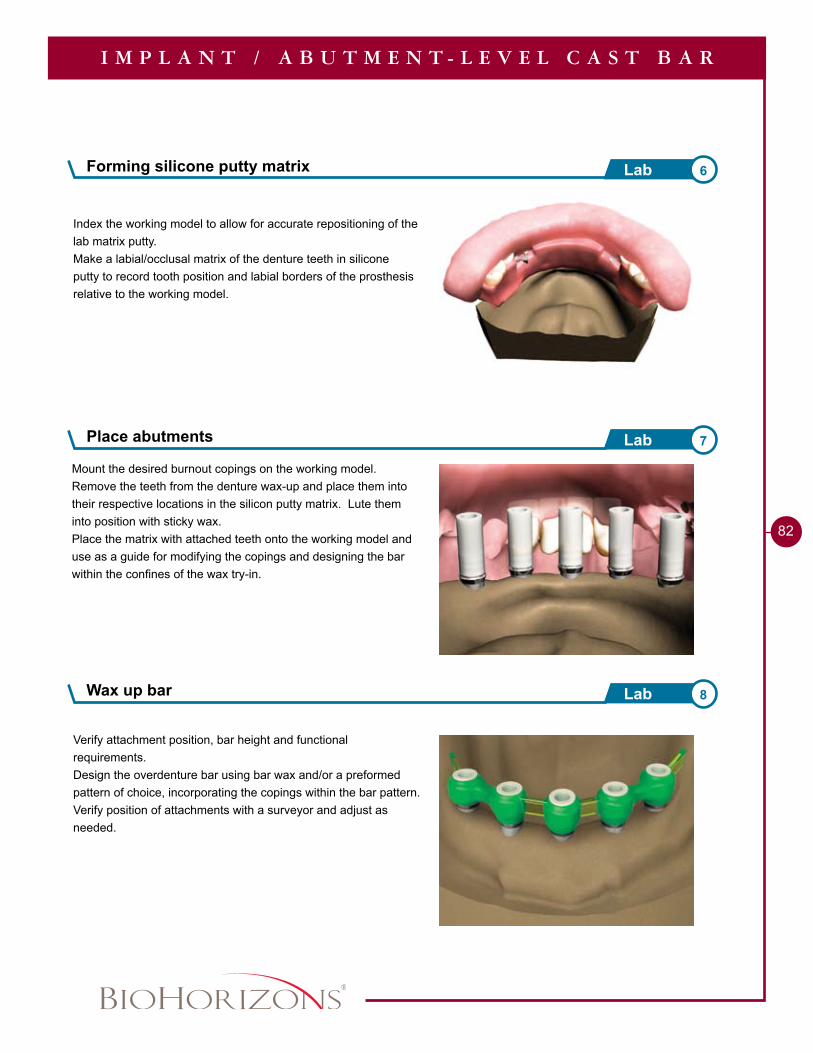
Forming silicone putty matrix 6Lab
82
Index the working model to allow for accurate repositioning of the lab matrix putty.Make a labial/occlusal matrix of the denture teeth in silicone putty to record tooth position and labial borders of the prosthesis relative to the working model.
Mount the desired burnout copings on the working model.Remove the teeth from the denture wax-up and place them into their respective locations in the silicon putty matrix. Lute them into position with sticky wax.Place the matrix with attached teeth onto the working model and use as a guide for modifying the copings and designing the bar within the confines of the wax try-in.
Verify attachment position, bar height and functional requirements.Design the overdenture bar using bar wax and/or a preformed pattern of choice, incorporating the copings within the bar pattern.Verify position of attachments with a surveyor and adjust as needed.
Place abutments 7Lab
I M P L A N T / A B U T M E N T - L E V E L C A S T B A R
Wax up bar 8Lab
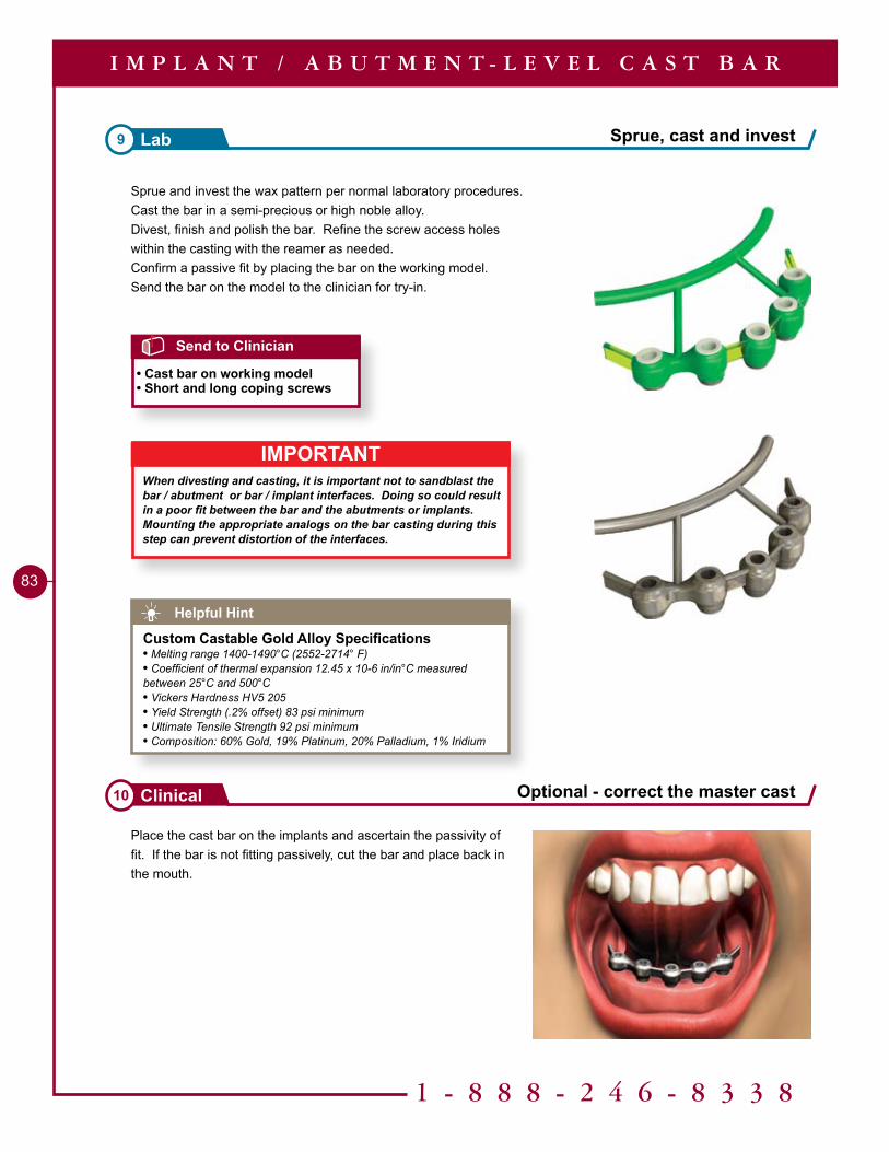
1 - 8 8 8 - 2 4 6 - 8 3 3 8
83
Place the cast bar on the implants and ascertain the passivity of fit. If the bar is not fitting passively, cut the bar and place back in the mouth.
Sprue and invest the wax pattern per normal laboratory procedures.Cast the bar in a semi-precious or high noble alloy. Divest, finish and polish the bar. Refine the screw access holes within the casting with the reamer as needed.Confirm a passive fit by placing the bar on the working model.Send the bar on the model to the clinician for try-in.
Sprue, cast and invest9 Lab
Optional - correct the master cast10 Clinical
I M P L A N T / A B U T M E N T - L E V E L C A S T B A R
Helpful Hint
Custom Castable Gold Alloy Specifications• Melting range 1400-1490°C (2552-2714° F)• Coefficient of thermal expansion 12.45 x 10⁻⁶ in/in°C measured between 25°C and 500°C• Vickers Hardness HV5 205• Yield Strength (.2% offset) 83 psi minimum• Ultimate Tensile Strength 92 psi minimum• Composition: 60% Gold, 19% Platinum, 20% Palladium, 1% Iridium
Send to Clinician
• Cast bar on working model• Short and long coping screws
IMPORTANTWhen divesting and casting, it is important not to sandblast the bar / abutment or bar / implant interfaces. Doing so could result in a poor fit between the bar and the abutments or implants.Mounting the appropriate analogs on the bar casting during this step can prevent distortion of the interfaces.
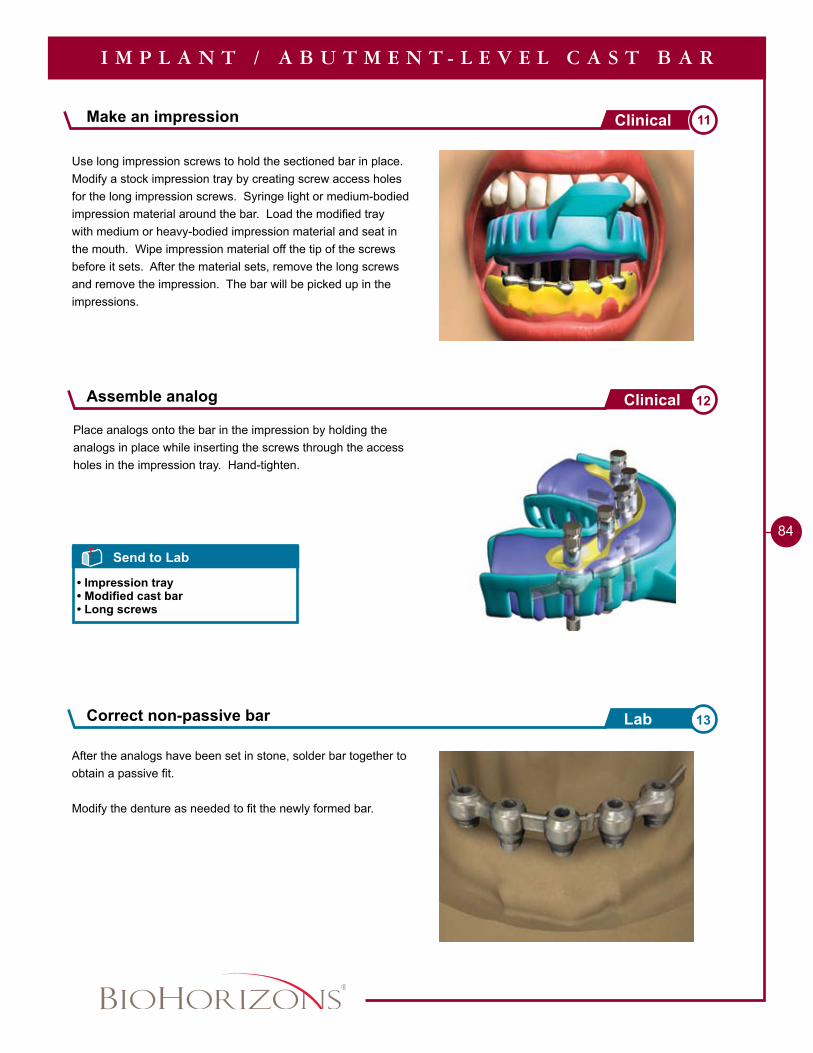
84
Use long impression screws to hold the sectioned bar in place. Modify a stock impression tray by creating screw access holes for the long impression screws. Syringe light or medium-bodied impression material around the bar. Load the modified tray with medium or heavy-bodied impression material and seat in the mouth. Wipe impression material off the tip of the screws before it sets. After the material sets, remove the long screws and remove the impression. The bar will be picked up in the impressions.
After the analogs have been set in stone, solder bar together to obtain a passive fit.
Modify the denture as needed to fit the newly formed bar.
Make an impression 11Clinical
Correct non-passive bar 13Lab
I M P L A N T / A B U T M E N T - L E V E L C A S T B A R
Send to Lab
• Impression tray• Modified cast bar• Long screws
Place analogs onto the bar in the impression by holding the analogs in place while inserting the screws through the access holes in the impression tray. Hand-tighten.
Assemble analog 12Clinical
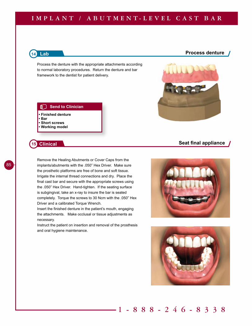
1 - 8 8 8 - 2 4 6 - 8 3 3 8
85Remove the Healing Abutments or Cover Caps from the implants/abutments with the .050” Hex Driver. Make sure the prosthetic platforms are free of bone and soft tissue. Irrigate the internal thread connections and dry. Place the final cast bar and secure with the appropriate screws using the .050” Hex Driver. Hand-tighten. If the seating surface is subgingival, take an x-ray to insure the bar is seated completely. Torque the screws to 30 Ncm with the .050” Hex Driver and a calibrated Torque Wrench.Insert the finished denture in the patient’s mouth, engaging the attachments. Make occlusal or tissue adjustments as necessary.Instruct the patient on insertion and removal of the prosthesis and oral hygiene maintenance.
Seat final appliance15 Clinical
I M P L A N T / A B U T M E N T - L E V E L C A S T B A R
Process the denture with the appropriate attachments according to normal laboratory procedures. Return the denture and bar framework to the dentist for patient delivery.
Process denture14 Lab
Send to Clinician
• Finished denture• Bar• Short screws• Working model
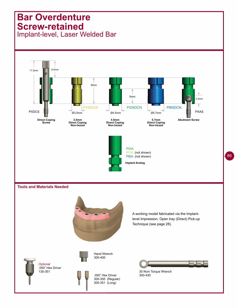
PYNDCN PGNDCN PBNDCNØ3.5mm Ø4.5mm Ø5.7mm
PGIAPYIA (not shown)PBIA (not shown)
3.5mm Direct Coping
Non-hexed
4.5mm Direct Coping
Non-hexed
5.7mm Direct Coping
Non-hexed
Implant Analog
9mm
5mm
Bar OverdentureScrew-retainedImplant-level, Laser Welded Bar
Optional.050” Hex Driver135-351
17.5mm 8.5mm
P
2.3mm
PXAS
P
Abutment ScrewDirect CopingScrew
PXDCS
Tools and Materials Needed
A working model fabricated via the Implant-level Impression, Open tray (Direct) Pick-up Technique (see page 28).
30 Ncm Torque Wrench300-430
Hand Wrench300-400
.050” Hex Driver300-350 (Regular)300-351 (Long)
86
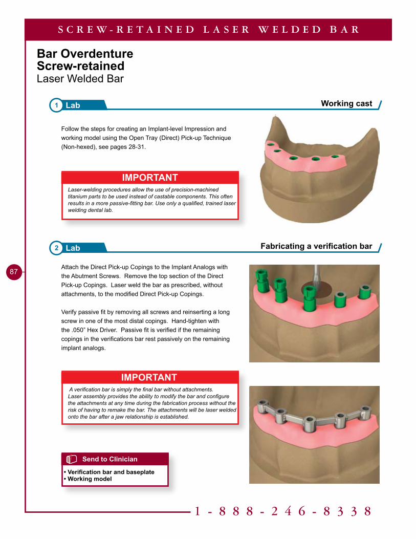
1 - 8 8 8 - 2 4 6 - 8 3 3 8
87
Bar OverdentureScrew-retainedLaser Welded Bar
Attach the Direct Pick-up Copings to the Implant Analogs with the Abutment Screws. Remove the top section of the Direct Pick-up Copings. Laser weld the bar as prescribed, without attachments, to the modified Direct Pick-up Copings.
Verify passive fit by removing all screws and reinserting a long screw in one of the most distal copings. Hand-tighten with the .050” Hex Driver. Passive fit is verified if the remaining copings in the verifications bar rest passively on the remaining implant analogs.
IMPORTANTLaser-welding procedures allow the use of precision-machined titanium parts to be used instead of castable components. This often results in a more passive-fitting bar. Use only a qualified, trained laser welding dental lab.
Follow the steps for creating an Implant-level Impression and working model using the Open Tray (Direct) Pick-up Technique (Non-hexed), see pages 28-31.
IMPORTANT A verification bar is simply the final bar without attachments.Laser assembly provides the ability to modify the bar and configure the attachments at any time during the fabrication process without the risk of having to remake the bar. The attachments will be laser welded onto the bar after a jaw relationship is established.
Working cast1 Lab
Fabricating a verification bar2 Lab
Send to Clinician
• Verification bar and baseplate• Working model
S C R E W - R E T A I N E D L A S E R W E L D E D B A R
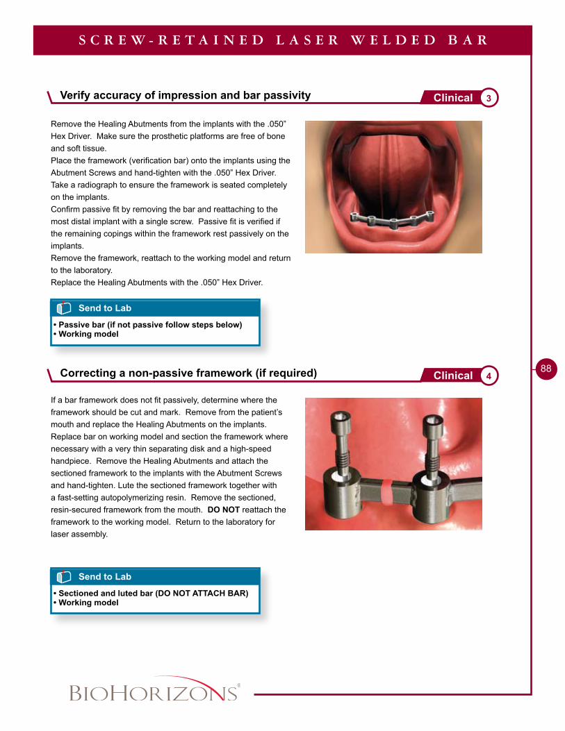
88
If a bar framework does not fit passively, determine where the framework should be cut and mark. Remove from the patient’s mouth and replace the Healing Abutments on the implants. Replace bar on working model and section the framework where necessary with a very thin separating disk and a high-speed handpiece. Remove the Healing Abutments and attach the sectioned framework to the implants with the Abutment Screws and hand-tighten. Lute the sectioned framework together with a fast-setting autopolymerizing resin. Remove the sectioned, resin-secured framework from the mouth. DO NOT reattach the framework to the working model. Return to the laboratory for laser assembly.
Remove the Healing Abutments from the implants with the .050” Hex Driver. Make sure the prosthetic platforms are free of bone and soft tissue.Place the framework (verification bar) onto the implants using the Abutment Screws and hand-tighten with the .050” Hex Driver. Take a radiograph to ensure the framework is seated completely on the implants.Confirm passive fit by removing the bar and reattaching to the most distal implant with a single screw. Passive fit is verified if the remaining copings within the framework rest passively on the implants.Remove the framework, reattach to the working model and return to the laboratory.Replace the Healing Abutments with the .050” Hex Driver.
Correcting a non-passive framework (if required) 4Clinical
S C R E W - R E T A I N E D L A S E R W E L D E D B A R
Send to Lab
• Sectioned and luted bar (DO NOT ATTACH BAR)• Working model
Send to Lab
• Passive bar (if not passive follow steps below)• Working model
Verify accuracy of impression and bar passivity 3Clinical
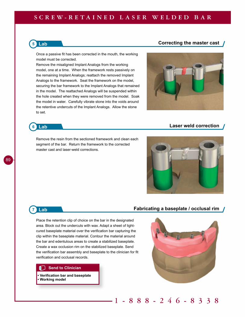
1 - 8 8 8 - 2 4 6 - 8 3 3 8
89
Place the retention clip of choice on the bar in the designated area. Block out the undercuts with wax. Adapt a sheet of light-cured baseplate material over the verification bar capturing the clip within the baseplate material. Contour the material around the bar and edentulous areas to create a stabilized baseplate. Create a wax occlusion rim on the stabilized baseplate. Send the verification bar assembly and baseplate to the clinician for fit verification and occlusal records.
Remove the resin from the sectioned framework and clean each segment of the bar. Return the framework to the corrected master cast and laser-weld corrections.
Laser weld correction6 Lab
Fabricating a baseplate / occlusal rim7 Lab
Send to Clinician
• Verification bar and baseplate• Working model
S C R E W - R E T A I N E D L A S E R W E L D E D B A R
Once a passive fit has been corrected in the mouth, the working model must be corrected.Remove the misaligned Implant Analogs from the working model, one at a time. When the framework rests passively on the remaining Implant Analogs; reattach the removed Implant Analogs to the framework. Seat the framework on the model, securing the bar framework to the Implant Analogs that remained in the model. The reattached Analogs will be suspended within the hole created when they were removed from the model. Soak the model in water. Carefully vibrate stone into the voids around the retentive undercuts of the Implant Analogs. Allow the stone to set.
Correcting the master cast5 Lab
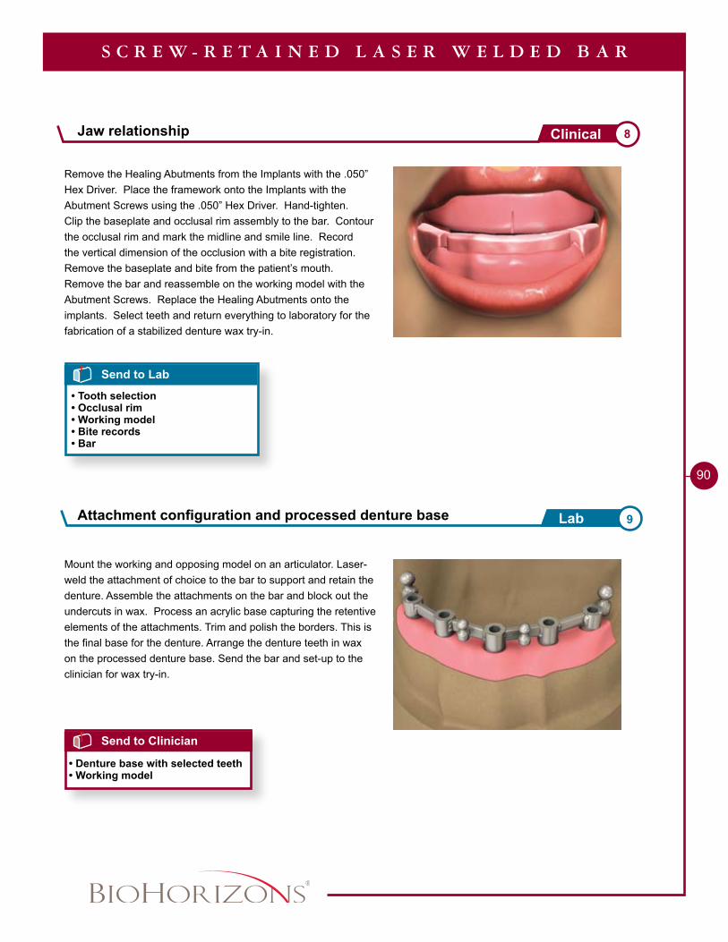
90
Remove the Healing Abutments from the Implants with the .050” Hex Driver. Place the framework onto the Implants with the Abutment Screws using the .050” Hex Driver. Hand-tighten.Clip the baseplate and occlusal rim assembly to the bar. Contour the occlusal rim and mark the midline and smile line. Record the vertical dimension of the occlusion with a bite registration. Remove the baseplate and bite from the patient’s mouth. Remove the bar and reassemble on the working model with the Abutment Screws. Replace the Healing Abutments onto the implants. Select teeth and return everything to laboratory for the fabrication of a stabilized denture wax try-in.
Mount the working and opposing model on an articulator. Laser-weld the attachment of choice to the bar to support and retain the denture. Assemble the attachments on the bar and block out the undercuts in wax. Process an acrylic base capturing the retentive elements of the attachments. Trim and polish the borders. This is the final base for the denture. Arrange the denture teeth in wax on the processed denture base. Send the bar and set-up to the clinician for wax try-in.
Send to Lab
• Tooth selection• Occlusal rim• Working model• Bite records• Bar
S C R E W - R E T A I N E D L A S E R W E L D E D B A R
Send to Clinician
• Denture base with selected teeth• Working model
Jaw relationship 8Clinical
Attachment configuration and processed denture base 9Lab
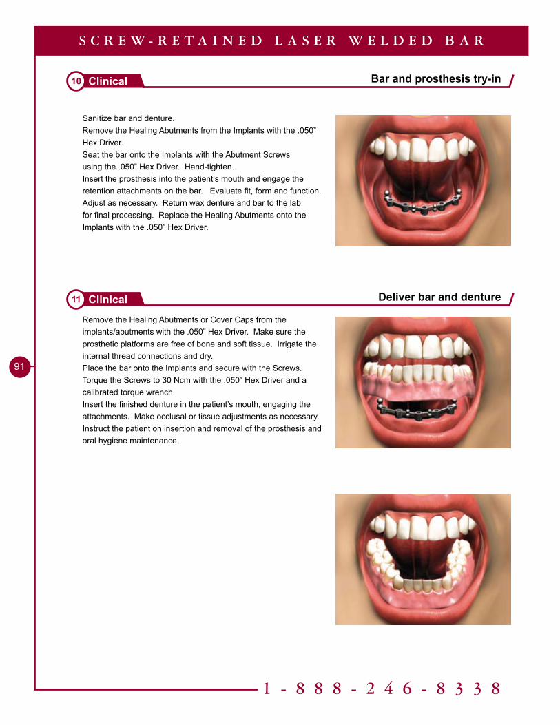
1 - 8 8 8 - 2 4 6 - 8 3 3 8
9�
Sanitize bar and denture.Remove the Healing Abutments from the Implants with the .050” Hex Driver.Seat the bar onto the Implants with the Abutment Screws using the .050” Hex Driver. Hand-tighten.Insert the prosthesis into the patient’s mouth and engage the retention attachments on the bar. Evaluate fit, form and function. Adjust as necessary. Return wax denture and bar to the lab for final processing. Replace the Healing Abutments onto the Implants with the .050” Hex Driver.
Remove the Healing Abutments or Cover Caps from the implants/abutments with the .050” Hex Driver. Make sure the prosthetic platforms are free of bone and soft tissue. Irrigate the internal thread connections and dry. Place the bar onto the Implants and secure with the Screws. Torque the Screws to 30 Ncm with the .050” Hex Driver and a calibrated torque wrench. Insert the finished denture in the patient’s mouth, engaging the attachments. Make occlusal or tissue adjustments as necessary.Instruct the patient on insertion and removal of the prosthesis and oral hygiene maintenance.
Bar and prosthesis try-in10 Clinical
Deliver bar and denture11 Clinical
S C R E W - R E T A I N E D L A S E R W E L D E D B A R

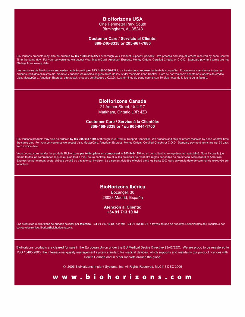
w w w . b i o h o r i z o n s . c o m
BioHorizons products may also be ordered by fax 905-944-1894 or through your Product Support Specialist. We process and ship all orders received by noon Central Time the same day. For your convenience we accept Visa, MasterCard, American Express, Money Orders, Certified Checks or C.O.D. Standard payment terms are net 30 days from invoice date.
Vous pouvez commander les produits BioHorizons par télécopieur en composant le 905-944-1894 ou en consultant votre représentant spécialisé. Nous livrons le jour même toutes les commandes reçues au plus tard à midi, heure centrale. De plus, les paiments peuvent être réglés par cartes de crédit Visa, MasterCard et American Express ou par mandat-poste, chèque certifié ou payable sur livraison. Le paiement doit être effectué dans les trente (30) jours suivant la date de commande retrouvée sur la facture.
BioHorizons products may also be ordered by fax 1-800-236-1271 or through your Product Support Specialist. We process and ship all orders received by noon Central Time the same day. For your convenience we accept Visa, MasterCard, American Express, Money Orders, Certified Checks or C.O.D. Standard payment terms are net 30 days from invoice date.
Los productos de BioHorizons se pueden también pedir por FAX 1-800-236-1271, o a través de su representante de la compañía. Procesamos y enviamos todas las órdenes recibidas el mismo día, siempre y cuando las mismas lleguen antes de las 12 del mediodía zona Central. Para su conveniencia aceptamos tarjetas de crédito Visa, MasterCard, American Express, giro postal, cheques certificados o C.O.D. Los términos de pago normal son 30 días netos de la fecha de la factura.
Los productos BioHorizons se pueden solicitar por teléfono, +34 91 713 10 84, por fax, +34 91 355 83 75, a través de uno de nuestros Especialistas de Producto o por correo electrónico: [email protected].
BioHorizons IbéricaBocángel, 38
28028 Madrid, España
Atención al Cliente: +34 91 713 10 84
BioHorizons USAOne Perimeter Park South
Birmingham, AL 35243
Customer Care / Servicio al Cliente: 888-246-8338 or 205-967-7880
BioHorizons Canada21 Amber Street, Unit # 7
Markham, Ontario L3R 4Z3
Customer Care / Service à la Clientèle: 866-468-8338 or / ou 905-944-1700
BioHorizons products are cleared for sale in the European Union under the EU Medical Device Directive 93/42/EEC. We are proud to be registered to ISO 13485:2003, the international quality management system standard for medical devices, which supports and maintains our product licences with
Health Canada and in other markets around the globe.
© 2006 BioHorizons Implant Systems, Inc. All Rights Reserved. ML0118 DEC 2006