Embed Size (px)
Citation preview
Textbook and Educational Aids
TE Y109JA01-PPRS
ProSafe-RS Training Manual
TE Y109JA01-PPRS 1st Edition
i
TE Y109JA01 PPRS 1st Edition: Jan 2009
Introduction
The objective of the Training manual is to acquaint the user with the system layout, operations screens and the terminologies used in the Prosafe-RS safety system.
This training module is designed to add more value to the traditional training. The participant can acquire basic knowledge on the Prosafe-RS system.
The Training manual consists of multiple chapters
Each chapter consists of multiple topics.
Media No. TEY109JA01-PPRS Edition:JAN 2009 All Rights Reserved Copyright © 2000, Yokogawa India Ltd
ii
TE Y109JA01-PPRS 1st Edition: Jan 2009
iii
TE Y109JA01-PPRS 1st Edition: Jan 2009
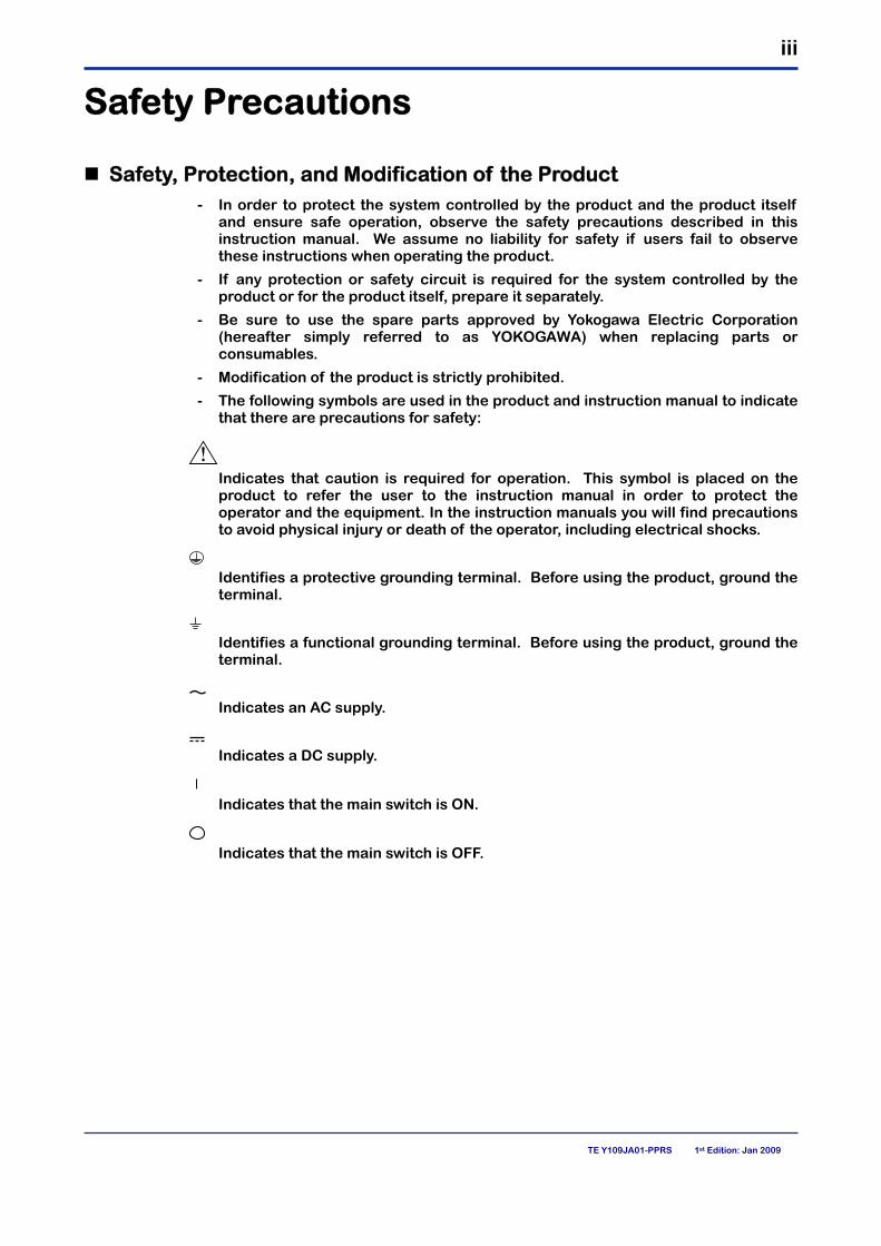
Safety Precautions
Safety, Protection, and Modification of the Product - In order to protect the system controlled by the product and the product itself
and ensure safe operation, observe the safety precautions described in this instruction manual. We assume no liability for safety if users fail to observe these instructions when operating the product.
- If any protection or safety circuit is required for the system controlled by the product or for the product itself, prepare it separately.
- Be sure to use the spare parts approved by Yokogawa Electric Corporation (hereafter simply referred to as YOKOGAWA) when replacing parts or consumables.
- Modification of the product is strictly prohibited.
- The following symbols are used in the product and instruction manual to indicate that there are precautions for safety:
Indicates that caution is required for operation. This symbol is placed on the
product to refer the user to the instruction manual in order to protect the operator and the equipment. In the instruction manuals you will find precautions to avoid physical injury or death of the operator, including electrical shocks.
Identifies a protective grounding terminal. Before using the product, ground the
terminal.
Identifies a functional grounding terminal. Before using the product, ground the
terminal.
Indicates an AC supply.
Indicates a DC supply.
Indicates that the main switch is ON.
Indicates that the main switch is OFF.
iv
TE Y109JA01-PPRS 1st Edition: Jan 2009
Notes on Handling Manuals - Please read the information thoroughly before using the product.
- The purpose of these manuals is not to warrant that the product is well suited to any particular purpose but rather to describe the functional details of the product.
- No part of the manuals may be transferred or reproduced without prior written consent from YOKOGAWA.
- YOKOGAWA reserves the right to make improvements in the manuals and product at any time, without notice or obligation.
- If you have any questions, or you find mistakes or omissions in the manuals, please contact our sales representative or your local distributor.
Warning and Disclaimer The product is provided on an "as is" basis. YOKOGAWA shall have neither liability nor responsibility to any person or entity with respect to any direct or indirect loss or damage arising from using the product or any defect of the product that YOKOGAWA cannot predict in advance.
Notes on Software - YOKOGAWA makes no warranties, either expressed or implied, with respect
to the software's merchantability or suitability for any particular purpose, except as specified in the terms of warranty.
- This product may be used on a one machine only. If you need to use the product on another machine, you must purchase another product.
- It is strictly prohibited to reproduce the product except for the purpose of backup.
- Store the CD-ROM (the original medium) in a safe place.
- It is strictly prohibited to perform any reverse-engineering operation, such as reverse compilation or reverse assembling on the product.
- No part of the product may be transferred, converted or sublet for use by any third party, without prior written consent from YOKOGAWA.
v
TE Y109JA01-PPRS 1st Edition: Jan 2009
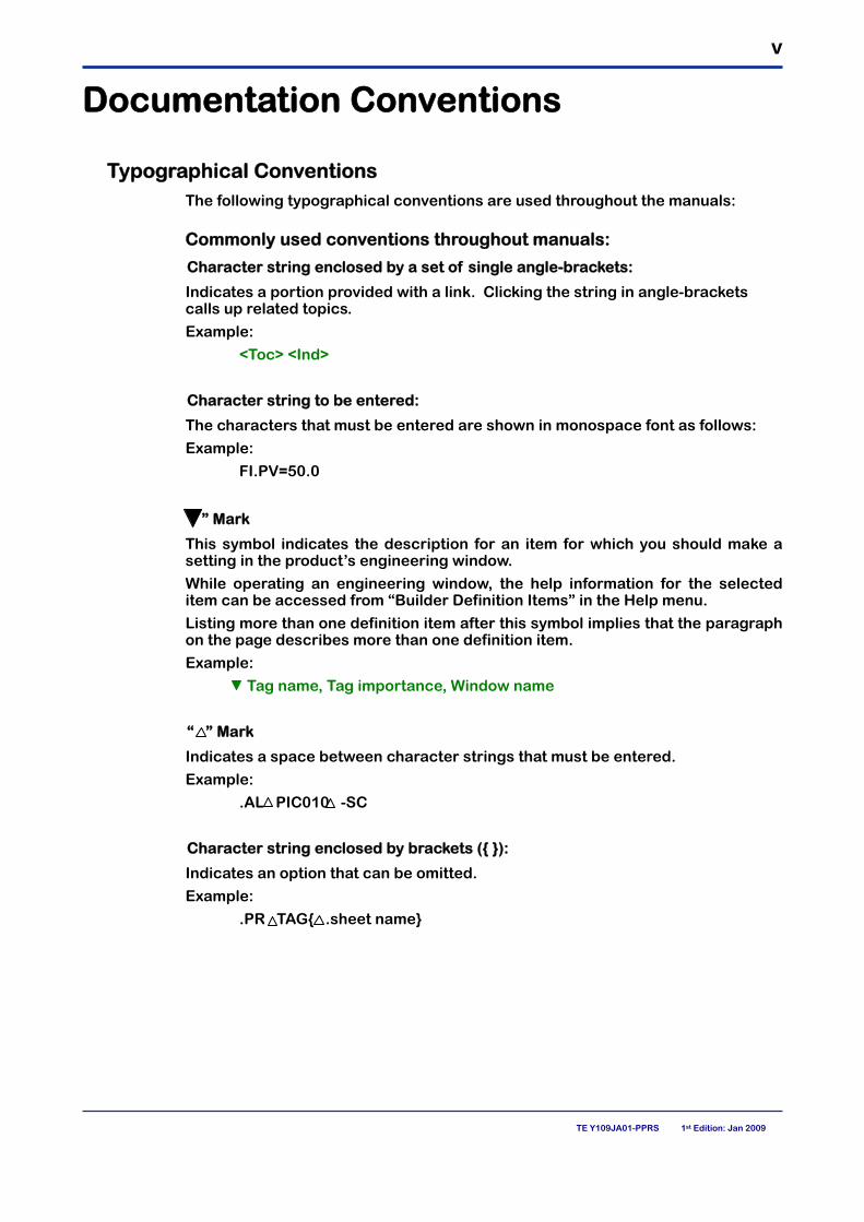
Documentation Conventions
� Typographical Conventions The following typographical conventions are used throughout the manuals:
� Commonly used conventions throughout manuals:
Character string enclosed by a set of single angle-brackets:
Indicates a portion provided with a link. Clicking the string in angle-brackets calls up related topics.
Example:
<Toc> <Ind>
Character string to be entered:
The characters that must be entered are shown in monospace font as follows:
Example:
FI.PV=50.0
“�” Mark
This symbol indicates the description for an item for which you should make a setting in the product’s engineering window.
While operating an engineering window, the help information for the selected item can be accessed from “Builder Definition Items” in the Help menu.
Listing more than one definition item after this symbol implies that the paragraph on the page describes more than one definition item.
Example:
Tag name, Tag importance, Window name
“ ” Mark
Indicates a space between character strings that must be entered.
Example:
.AL PIC010 -SC
Character string enclosed by brackets ({ }):
Indicates an option that can be omitted.
Example:
.PR TAG{ .sheet name}
vi
TE Y109JA01-PPRS 1st Edition: Jan 2009
Conventions used to show key or button operations:
Characters enclosed by brackets ([ ]):
Characters enclosed by brackets within any description on a key or button operation, indicate either a key on the HIS (Human Interface Station) keyboard, a key on the operation keyboard, a button name on a window, or an item displayed on a window.
Example:
To alter the function, press the [ESC] key.
� Conventions used in command syntax or program statements:
The following conventions are used within a command syntax or program statement format:
Characters enclosed by angle-brackets:
Indicate character strings that user can specify freely according to certain guidelines.
Example:
#define <Identifier><Character string>
“...” Mark
Indicates that the previous command or argument may be repeated.
Example:
Imax (arg1, arg2, ...)
Characters enclosed by brackets ([ ]):
Indicate those character strings that can be omitted.
Example:
sysalarm format_string [output_value ...]
Characters enclosed by separators ( ):
Indicate those character strings that can be selected from more than one option.
Example:
opeguide <format_character_string> [, <output_value> ...]OG,<element number>
vii
TE Y109JA01-PPRS 1st Edition: Jan 2009
Symbol Marks Throughout this manual, you will find several different types of symbols are used to identify different sections of text. This section describes these icons.
CAUTION
Identifies instructions that must be observed in order to avoid physical injury and electric shock or death of the operator.
WARNING Identifies instructions that must be observed in order to prevent the software
or hardware from being damaged or the system from becoming faulty.
CAUTION Identifies additional information required to understand operations or
functions.
TIP
Identifies additional information.
SEE ALSO
Identifies a source to be referred to.
Clicking a reference displayed in green can call up its source, while clicking a reference displayed in black cannot.
Drawing Conventions Some drawings may be partially emphasized, simplified, or omitted, for the convenience of description.
Some screen images depicted in the manual may have different display positions or character types (e.g., the upper / lower case). Also note that some of the images contained in this manual are display examples.
viii
TE Y109JA01-PPRS 1st Edition: Jan 2009
Copyright and Trademark Notices
� All Rights Reserved The copyrights of the programs and online manual contained in the CD-ROM are reserved.
The online manual is protected by the PDF security from modification, however, it can be output via a printer. Printing out the online manual is only allowed for the purpose of using the product. When using the printed information of the online manual, check if the version is the most recent one by referring to the CD-ROM's version.
No part of the online manual may be transferred, sold, distributed (including delivery via a commercial PC network or the like), or registered or recorded on videotapes.
� Trademark Acknowledgments - CENTUM is a registered trademark of YOKOGAWA.
- Microsoft, Windows, Windows NT, Excel, Visual Basic, and Internet Explorer are registered trademarks of Microsoft Corporation.
- Adobe and Acrobat are trademarks of Adobe Systems Incorporated and registered within particular jurisdictions.
- Ethernet is a registered trademark of XEROX Corporation.
- Java is a registered trademark of Sun Microsystems,Inc.
- Netscape Communicator is a registered trademark of Netscape Communications Corporation.
- NetDDE is a registered trademark of Wonderware Corporation.
- MELSEC-A is a registered trademark of Mitsubishi Electric Corporation.
- Modicon and Modbus are registered trademarks of AEG Schneider Automation.
- Memocon-SC is a registered trademark of Yaskawa Electric Corporation.
- PLC is a registered trademark of Allen-Bradley Company Inc.
- SYSMAC is a registered trademark of OMRON Corporation.
- SIEMENS and SIMATIC are registered trademarks of Siemens Industrial Automation Ltd.
- "FOUNDATION" in "FOUNDATION Fieldbus" is a trademark of Fieldbus Foundation.
- All other company and product names mentioned in this manual are trademarks or registered trademarks of their respective companies.
- We do not use TM or (R) mark to indicate those trademarks or registered trademarks in this manual.
TE Y109JA01-PPRS
1
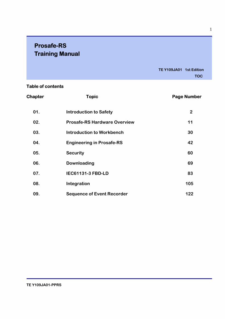
Table of contents Chapter Topic Page Number
01. Introduction to Safety 2
02. Prosafe-RS Hardware Overview 11
03. Introduction to Workbench 30
04. Engineering in Prosafe-RS 42
05. Security 60 06. Downloading 69
07. IEC61131-3 FBD-LD 83
08. Integration 105 09. Sequence of Event Recorder 122
Prosafe-RS Training Manual
TE Y109JA01 1st Edition
TOC

TE Y109JA01-PPRS
2
1. INTRODUCTION TO SAFETY
TE Y109JA01-PPRS
3
Table of contents
1.1 What is a Safety system?
1.2 Why Safety?
1.3 Demand for Protective Action
1.4 Function of a SIS 1.5 Safety Systems and their features
1.5.1 Applications of a safety system
1.5.2 Differences between DCS and SIS
1.6 Safety standards
1.7 Properties of a Safety System
1.7.1 System failures
1.7.2 Process safety time
1.7.3 Reliability
1.8 Safety System Architecture 1.9 Yokogawa’s Contribution to Industrial Safety

TE Y109JA01-PPRS
4
1.1
What is a Safety system?
A Safety system is a system that provides an independent and predetermined emergency shutdown path in case a process runs out of control.
A process that run out of control can cause:
• Damage to People ( Both on & off site)
• Damage to Environment
• Loss of Equipment
• Loss of Production and there by loss of money

TE Y109JA01-PPRS
5
1.2 Why Safety?
Safety is defined as a "situation in which the risk is not higher than the risk limit". Safety system takes care to keep the situation within the risk limit.
1.3 Demand for Protective Action
Sometimes things go wrong in the process and an operator takes action to keep the process within limits and It Works!!!!
If that does not work, there may be an accident...
TE Y109JA01-PPRS
6
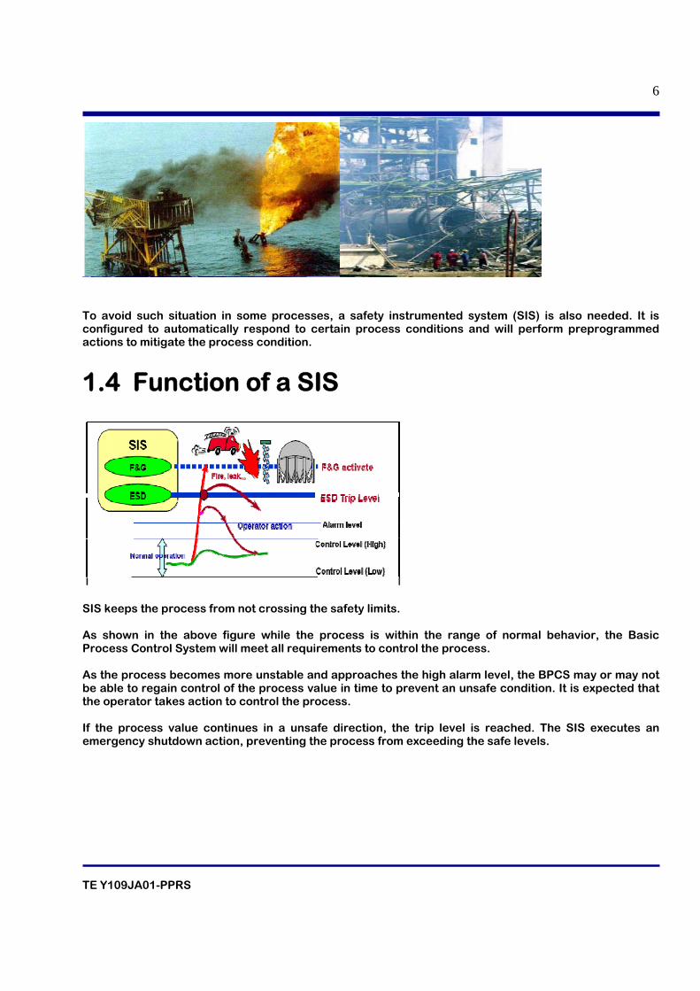
To avoid such situation in some processes, a safety instrumented system (SIS) is also needed. It is configured to automatically respond to certain process conditions and will perform preprogrammed actions to mitigate the process condition.
1.4 Function of a SIS
SIS keeps the process from not crossing the safety limits. As shown in the above figure while the process is within the range of normal behavior, the Basic Process Control System will meet all requirements to control the process. As the process becomes more unstable and approaches the high alarm level, the BPCS may or may not be able to regain control of the process value in time to prevent an unsafe condition. It is expected that the operator takes action to control the process. If the process value continues in a unsafe direction, the trip level is reached. The SIS executes an emergency shutdown action, preventing the process from exceeding the safe levels.
TE Y109JA01-PPRS
7
1.5 Safety Systems and their features. Safety system is a control system comprising of sensors, logic solvers and final control elements designed to take process to a safe state when predetermined conditions are violated .
1.5.1 Applications of a safety system.
Some of the applications of the safety system are
• Emergency shutdown.
• Burner management.
• Fire and gas detection.
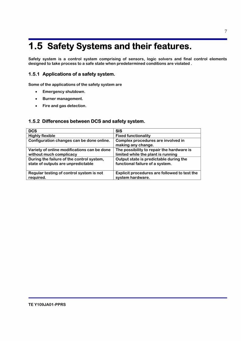
1.5.2 Differences between DCS and safety system. DCS SIS Highly flexible Fixed functionality Configuration changes can be done online. Complex procedures are involved in
making any change. Variety of online modifications can be done without much complicacy
The possibility to repair the hardware is limited while the plant is running
During the failure of the control system, state of outputs are unpredictable
Output state is predictable during the functional failure of a system.
Regular testing of control system is not required.
Explicit procedures are followed to test the system hardware.

TE Y109JA01-PPRS
8
1.6 Safety standards The two most important standards for functional safety are IEC 61508 and 61511.The first one is used to design and manufacture safety systems. The IEC 61511 is normally used during the design, startup and operation of a complete plant. The standards specify all kinds of requirements for the complete life cycle of the plant. It starts with hazards analysis and definition of safety functions, then the design and testing of the safety system, requirements for operation and maintenance.
1.7 Properties of a Safety System 1.7.1 System failures Failures can be divided in to
• Hardware failures
• Systematic Failures
Hardware failures are caused by the malfunctioning of the hardware component. Stress is the cause for failure. The stresses can be of different types. Below are the few examples.
• Heat
• Chemical Corrosion
• Humidity
• Vibration
• Electrostatic Discharge
• Operational and maintenance Errors
Systematic failures are related to errors in software design. This can be corrected by reprogramming. 1.7.2 Process safety time. Process safety time is the maximum time between the demand and the necessary shutdown action. It is a property of the process. Reaction time of the safety function should be with in the process safety time. 1.7.3 Reliability Reliability is a combination of safety integrity and availability.
TE Y109JA01-PPRS
9
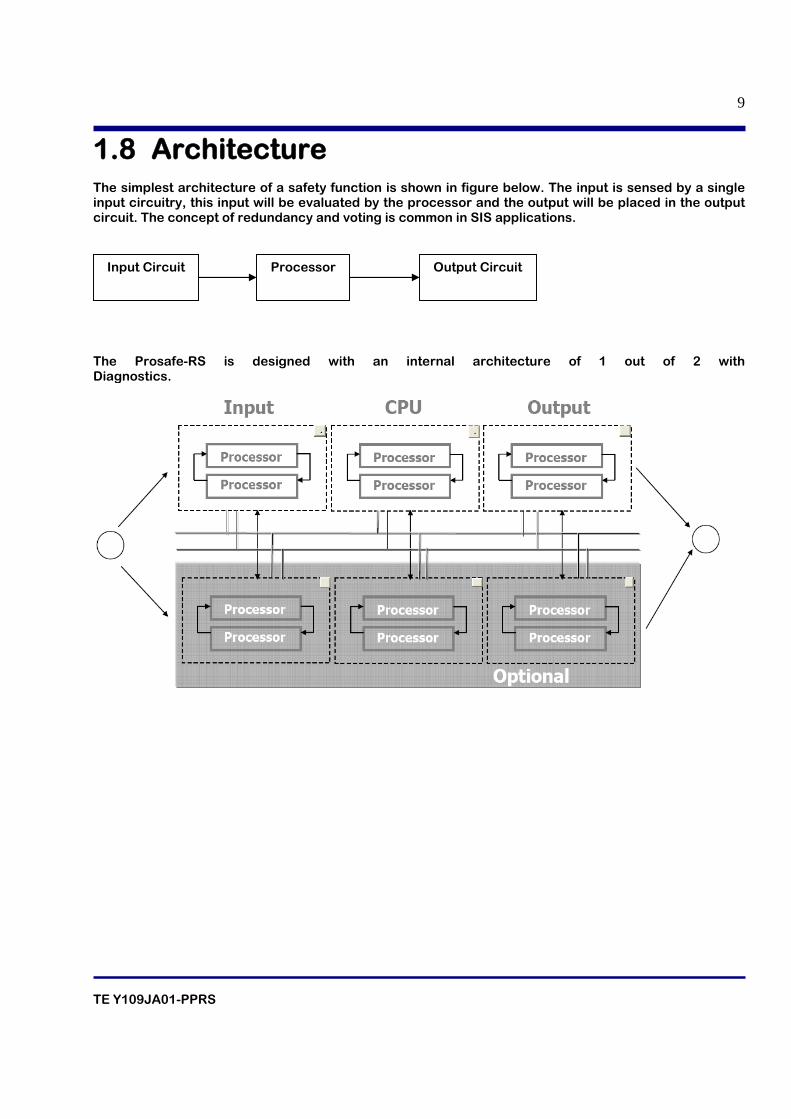
1.8 Architecture The simplest architecture of a safety function is shown in figure below. The input is sensed by a single input circuitry, this input will be evaluated by the processor and the output will be placed in the output circuit. The concept of redundancy and voting is common in SIS applications.
The Prosafe-RS is designed with an internal architecture of 1 out of 2 with Diagnostics.
Input Circuit Processor Output Circuit

TE Y109JA01-PPRS
10
1.9 Yokogawa’s Contribution to Industrial Safety
Industrial automation is at the heart of Yokogawa's business. For more than five decades, we have been developing the most comprehensive process control solutions for process industries worldwide. Deeply ingrained in our corporate culture are the principles that reliability is a top priority, and that system continuity and expandability are essentials. To deliver a control platform in which our customers can have full confidence in solutions for the evolving safety environment, Yokogawa proudly releases ProSafe-RS, a revolution in safety instrumented systems.
TE Y109JA01-PPRS
11
2. PROSAFE-RS HARDWARE OVERVIEW
TE Y109JA01-PPRS
12
Table of contents
2.1 Introduction
2.1.1 Overview of ProSafe-RS
2.1.2 Safety Application
2.2 System Configuration
2.2.1 Prosafe RS basic configuration
2.2.2 Prosafe RS/Centum CS 3000 Integration structure
2.3 Components of a Safety Control Station.
2.4 Components of a Safety control Unit
2.4.1 Standard type Safety Control Unit
2.4.2 Wide Range temperature type Safety Control Unit
2.4.3 Components of Safety Control Unit SSC10D (for Vnet)
2.4.4 Components of Safety Control Unit SSC50D (for Vnet/IP)
2.4.5 Processor module
2.4.6 Battery
2.4.7 LED display on processor module
2.4.8 Setting Switches on processor module
2.4.9 ESB coupler module
2.4.10 Vnet Coupler module
2.5 Configuration of Safety Node unit
2.5.1 Input/Output modules
2.5.1.1 Analog input module
2.5.1.2 Digital input/output module
2.5.1.3 Communication module
2.5.1.4 Accessories related to input/output module
2.6 Addressing 2.6.1. Setting Domain Address
2.6.2 Setting station address
2.6.3 Setting Node number on Safety node

TE Y109JA01-PPRS
13
2.7 Redundancy
2.7.1 CPU module
2.7.2 Input/Output module
2.7.3 Vnet communication
2.7.4 Power supply module
2.7.5 ESB bus
2.7.6 SB Bus
TE Y109JA01-PPRS
14
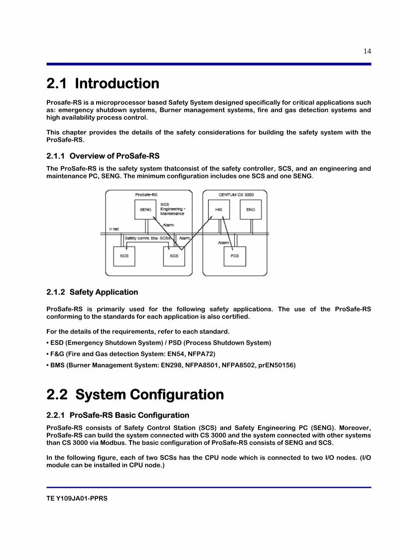
2.1 Introduction Prosafe-RS is a microprocessor based Safety System designed specifically for critical applications such as: emergency shutdown systems, Burner management systems, fire and gas detection systems and high availability process control. This chapter provides the details of the safety considerations for building the safety system with the ProSafe-RS. 2.1.1 Overview of ProSafe-RS
The ProSafe-RS is the safety system thatconsist of the safety controller, SCS, and an engineering and maintenance PC, SENG. The minimum configuration includes one SCS and one SENG.
2.1.2 Safety Application ProSafe-RS is primarily used for the following safety applications. The use of the ProSafe-RS conforming to the standards for each application is also certified. For the details of the requirements, refer to each standard.
• ESD (Emergency Shutdown System) / PSD (Process Shutdown System)
• F&G (Fire and Gas detection System: EN54, NFPA72)
• BMS (Burner Management System: EN298, NFPA8501, NFPA8502, prEN50156)
2.2 System Configuration 2.2.1 ProSafe-RS Basic Configuration
ProSafe-RS consists of Safety Control Station (SCS) and Safety Engineering PC (SENG). Moreover, ProSafe-RS can build the system connected with CS 3000 and the system connected with other systems than CS 3000 via Modbus. The basic configuration of ProSafe-RS consists of SENG and SCS. In the following figure, each of two SCSs has the CPU node which is connected to two I/O nodes. (I/O module can be installed in CPU node.)
TE Y109JA01-PPRS
15
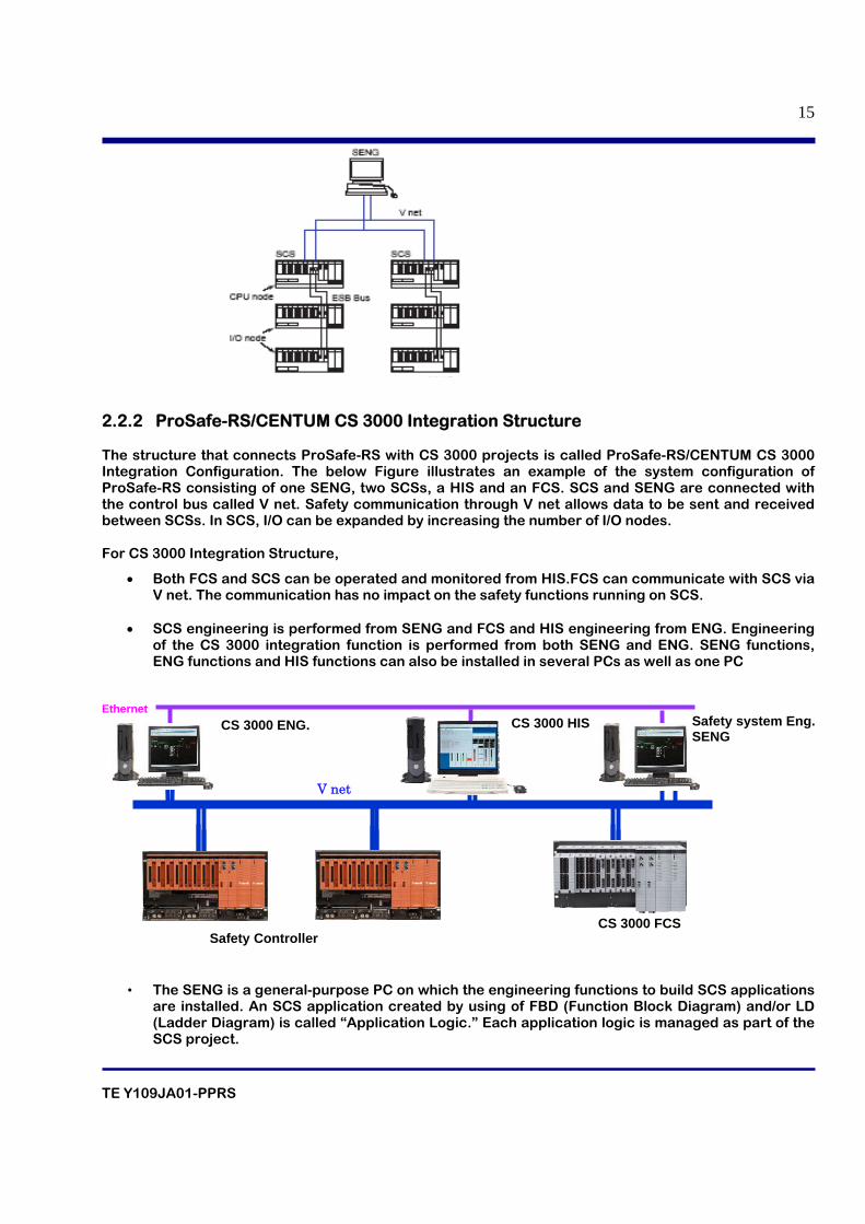
2.2.2 ProSafe-RS/CENTUM CS 3000 Integration Structure The structure that connects ProSafe-RS with CS 3000 projects is called ProSafe-RS/CENTUM CS 3000 Integration Configuration. The below Figure illustrates an example of the system configuration of ProSafe-RS consisting of one SENG, two SCSs, a HIS and an FCS. SCS and SENG are connected with the control bus called V net. Safety communication through V net allows data to be sent and received between SCSs. In SCS, I/O can be expanded by increasing the number of I/O nodes. For CS 3000 Integration Structure,
• Both FCS and SCS can be operated and monitored from HIS.FCS can communicate with SCS via V net. The communication has no impact on the safety functions running on SCS.
• SCS engineering is performed from SENG and FCS and HIS engineering from ENG. Engineering
of the CS 3000 integration function is performed from both SENG and ENG. SENG functions, ENG functions and HIS functions can also be installed in several PCs as well as one PC
• The SENG is a general-purpose PC on which the engineering functions to build SCS applications are installed. An SCS application created by using of FBD (Function Block Diagram) and/or LD (Ladder Diagram) is called “Application Logic.” Each application logic is managed as part of the SCS project.
Ethernet CS 3000 ENG.
V net
CS 3000 HIS
CS 3000 FCS Safety Controller
Safety system Eng. SENG
TE Y109JA01-PPRS
16
• The ENG is a general-purpose PC on which the CS 3000 system generation function is installed. Each CS 3000 application generated on the ENG is managed as part of the CS 3000 project.
• The HIS is a general-purpose PC on which the CS 3000 operation function is installed.
• SCS tags can be accessed from FCS. The data exchange between the SCS and the FCS will not
affect the safety communication between two SCS.
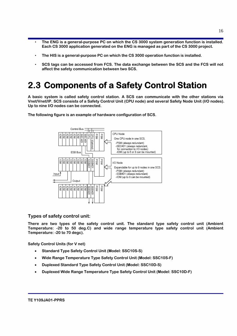
2.3 Components of a Safety Control Station A basic system is called safety control station. A SCS can communicate with the other stations via Vnet/Vnet/IP. SCS consists of a Safety Control Unit (CPU node) and several Safety Node Unit (I/O nodes). Up to nine I/O nodes can be connected. The following figure is an example of hardware configuration of SCS.
Types of safety control unit:
There are two types of the safety control unit. The standard type safety control unit (Ambient Temperature: -20 to 50 deg.C) and wide range temperature type safety control unit (Ambient Temperature: -20 to 70 degc).
Safety Control Units (for V net)
• Standard Type Safety Control Unit (Model: SSC10S-S)
• Wide Range Temperature Type Safety Control Unit (Model: SSC10S-F)
• Duplexed Standard Type Safety Control Unit (Model: SSC10D-S)
• Duplexed Wide Range Temperature Type Safety Control Unit (Model: SSC10D-F)
TE Y109JA01-PPRS
17
Safety Control Units (for Vnet/IP)
• Standard Type Safety Control Unit for Vnet/IP (Model: SSC50S-S)
• Wide Range Temperature Type Safety Control Unit for Vnet/IP (Model: SSC50S-F)
• Duplexed Standard Type Safety Control Unit for Vnet/IP (Model: SSC50D-S)
• Duplexed Wide Range Temperature Type Safety Control Unit for Vnet/IP (Model:SSC50D-F)
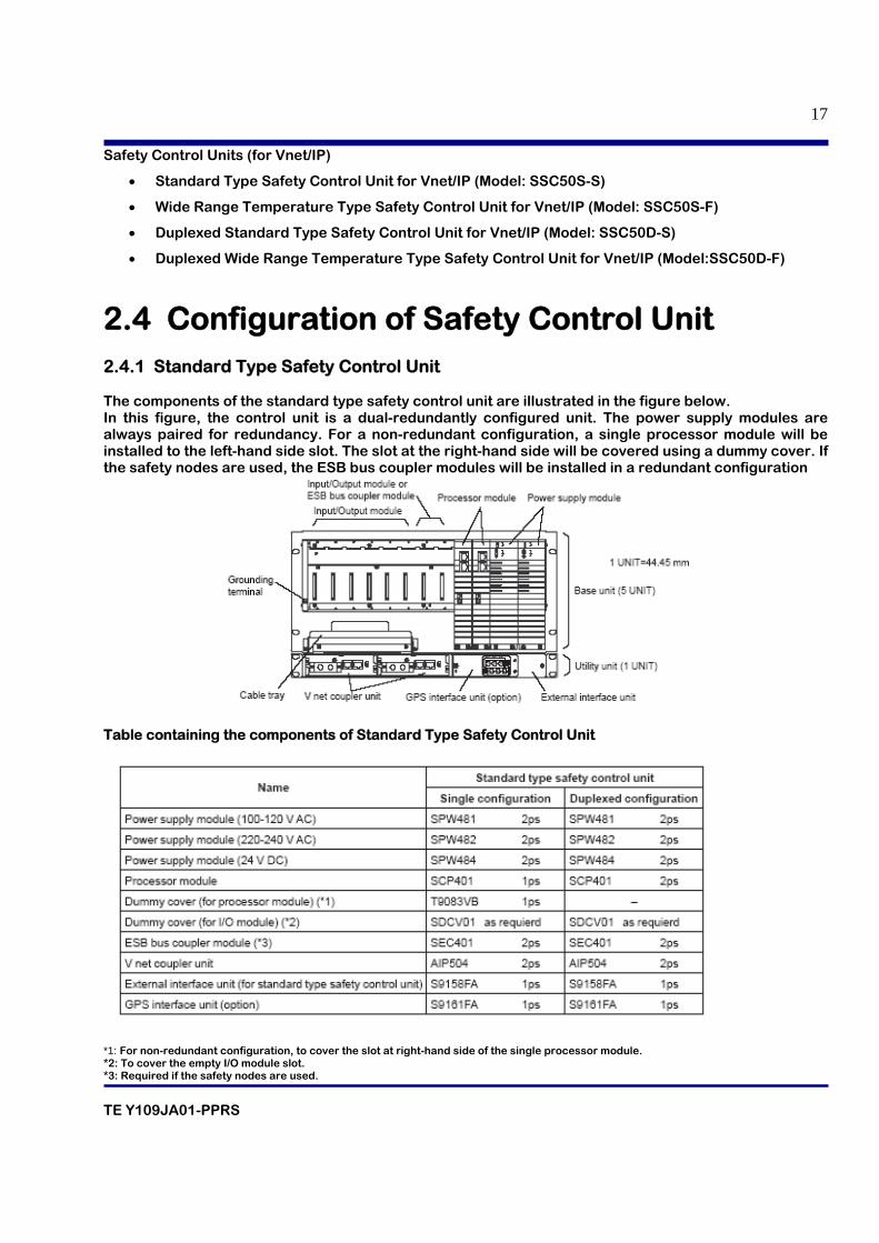
2.4 Configuration of Safety Control Unit 2.4.1 Standard Type Safety Control Unit The components of the standard type safety control unit are illustrated in the figure below. In this figure, the control unit is a dual-redundantly configured unit. The power supply modules are always paired for redundancy. For a non-redundant configuration, a single processor module will be installed to the left-hand side slot. The slot at the right-hand side will be covered using a dummy cover. If the safety nodes are used, the ESB bus coupler modules will be installed in a redundant configuration
Table containing the components of Standard Type Safety Control Unit
*1: For non-redundant configuration, to cover the slot at right-hand side of the single processor module. *2: To cover the empty I/O module slot. *3: Required if the safety nodes are used.
TE Y109JA01-PPRS
18
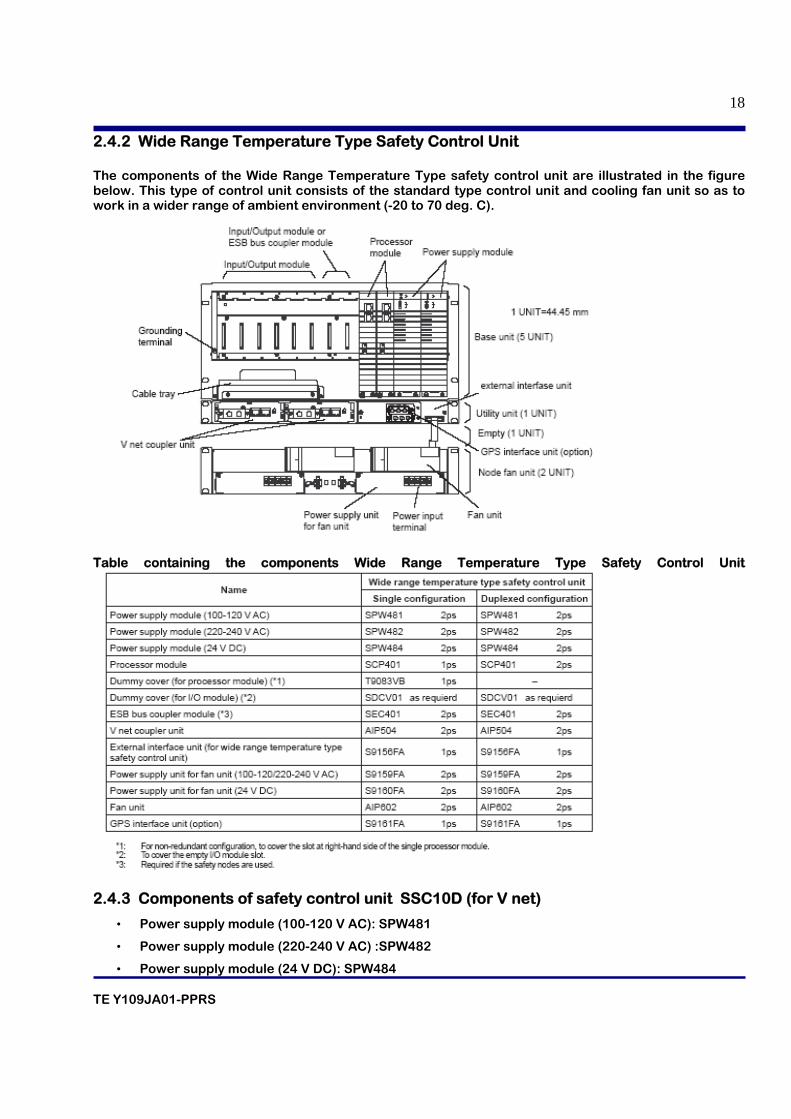
2.4.2 Wide Range Temperature Type Safety Control Unit The components of the Wide Range Temperature Type safety control unit are illustrated in the figure below. This type of control unit consists of the standard type control unit and cooling fan unit so as to work in a wider range of ambient environment (-20 to 70 deg. C).
Table containing the components Wide Range Temperature Type Safety Control Unit
2.4.3 Components of safety control unit SSC10D (for V net)
• Power supply module (100-120 V AC): SPW481
• Power supply module (220-240 V AC) :SPW482
• Power supply module (24 V DC): SPW484

TE Y109JA01-PPRS
19
• Processor module SCP401
• Dummy cover (for processor module): T9083VB
• Dummy cover (for I/O module): SDCV01
• ESB bus coupler module :SEC401
• V net coupler unit :AIP504
• External interface unit (for standard type safety control unit) :S9158FA
• GPS interface unit (option): S9161FA
2.4.4 Components of safety control unit SSC50D (for Vnet/IP)
• Power supply module (100-120 V AC)
• SPW481 Power supply module (220-240 V AC) SPW482
• Power supply module (24 V DC) SPW484
• Processor module SCP451
• Dummy cover (for I/O module) SDCV01
• ESB bus coupler module SEC401 2ps
• External interface unit (for standard type safety control unit) S9158FA 1ps
2.4.5 Processor module
• Control algorithm calculations are performed in the processor modules.
• Two types of processor modules are available: one for V net (Model: SCP401) and the other for
Vnet/IP (Model: SCP451).
2.4.6 Battery
In order to protect the processor module management information (in the storage memory) during power failure, the Li batteries are used. Since the application program information is stored in the non-volatile memories, thus battery backup is not required. Battery Back-up Specifications
Battery life Changes according to the ambient temperature. • Three years if the average ambient temperature is 30 deg. C or less • One year and a half if the average ambient temperature is 40 deg. C or less • Nine months if the average ambient temperature is 50 deg. C or less
TE Y109JA01-PPRS
20
2.4.7 LED display on processor module HRDY:
The processor module performs self diagnosis. If the processor module hardware is functioning normally, the green light turns on. If abnormality is found, the light turns off.
RDY:
The green light turns on if both the hardware and software are functioning normally. If either of them is abnormal, the light turns off.
CTRL:
The green light turns on if the processor module is performing control. If the processor module is standby, the light turns off. During the startup phase, the processor module installed at the right-hand side performs control.
COPY:
In the dual-redundant type safety control unit, the green light turns on when program copy is executed and turns off when program copy is completed. When a processor module has been replaced or when the unit is stopped and then started again, the standby-side processor module automatically copies the program of the control-side processor module. When copy is completed, the light turns off. In the basic (single) safety control unit, the light is always off.
RCV:
Indicates the control bus communication status. 1 stands for control bus bus1 while 2 stands for control bus bus2. When receiving communication frames, the lamp flashes in green, otherwise the lamp is off.
SND:
Indicates the control bus communication status. 1 stands for control bus bus1 while 2 stands for control bus bus2. When sending communication frames, the lamp flashes in green, otherwise the lamp is off.
SYNC:
If the module is synchronizing with V net clock or IRIG-B clock, this lamp turns on green. Otherwise it turns off. If the module is synchronizing with Vnet/IP clock, this lamp turns on green. Otherwise it turns off.
SCTY:
The green light turns on when the security level of the SCS is online-level. If the security level of the SCS is offline-level, the light turns off.
TE Y109JA01-PPRS
21
2.4.8 Setting switches on processor module START/STOP:
This maintenance switch is used for forcing the processor module CPU stop or restart. If this switch is pressed when the processor module is still operating, the CPU will stop. If this switch is pressed when the processor module is not operating, the CPU will restart. This switch is located inside a hole next to the START/STOP sign. Push the switch using a non conductive slender bar of around 1 to 2 mm diameter.
Battery ON/OFF switch:
When this switch is on, battery backup is activated for protecting the processor module management information (in the storage memory) during power failure.
ON: Enables the backup. Select this position during normal operation.
OFF: Disables the backup.
Front setting switch (6-bit DIP switch):
PORT: Port for maintenance (In usual operations, set to 0 position). DOMN: Indicates the control bus domain number on SATUS LED when this bit is set to 1position. (In usual operations, set to 0 position). STA: Indicates the control bus station number on SATUS LED when this bit is set to 1position. (In usual operations, set to 0 position).
ON : Force
OFF: Auto
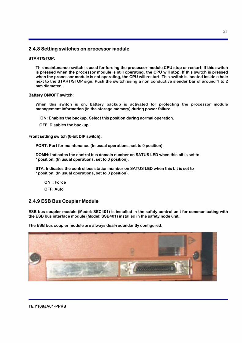
2.4.9 ESB Bus Coupler Module ESB bus coupler module (Model: SEC401) is installed in the safety control unit for communicating with the ESB bus interface module (Model: SSB401) installed in the safety node unit. The ESB bus coupler module are always dual-redundantly configured.
TE Y109JA01-PPRS
22
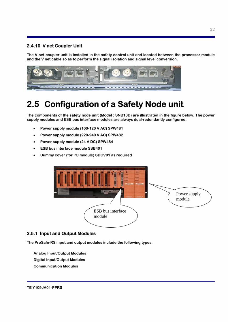
2.4.10 V net Coupler Unit The V net coupler unit is installed in the safety control unit and located between the processor module and the V net cable so as to perform the signal isolation and signal level conversion.
2.5 Configuration of a Safety Node unit The components of the safety node unit (Model : SNB10D) are illustrated in the figure below. The power supply modules and ESB bus interface modules are always dual-redundantly configured.
• Power supply module (100-120 V AC) SPW481
• Power supply module (220-240 V AC) SPW482
• Power supply module (24 V DC) SPW484
• ESB bus interface module SSB401
• Dummy cover (for I/O module) SDCV01 as required
2.5.1 Input and Output Modules The ProSafe-RS input and output modules include the following types:
Analog Input/Output Modules
Digital Input/Output Modules
Communication Modules
ESB bus interface module
Power supply module
TE Y109JA01-PPRS
23
2.5.1.1 Analog input modules Analog input modules are used to read analog signal inputs and convert signals. External View of Analog Input Module The connections with the analog input modules vary with the types of adapters. Pressure clamp terminals, terminal boards (with signal cable adapters) and MIL cables are used for the connections. The ProSafe-RS analog input modules consist of the following types: • SAI143: 4 to 20 mA input, 16 Channels, Isolated.
• SAV144: 1 to 5V DC/1 to 10V DC input, 16 Channels, Isolated.
• SAI533 : 4 to 20 mA output, 8 Channels, Isolated.
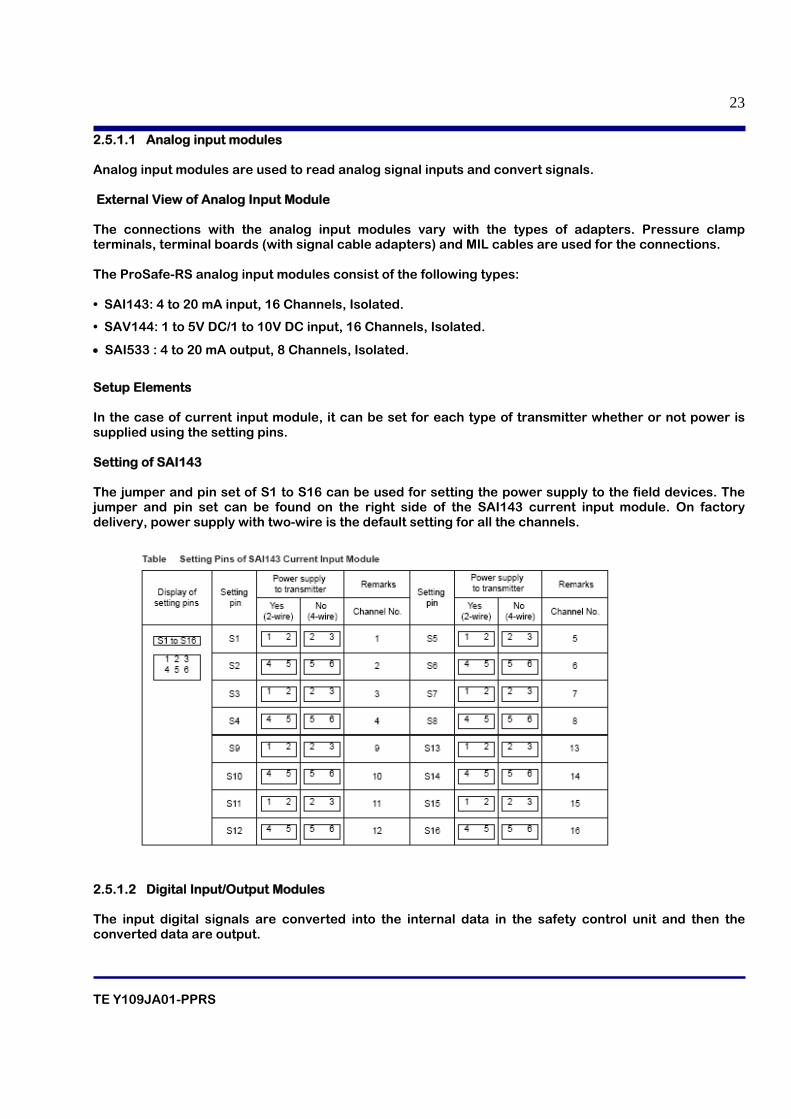
Setup Elements In the case of current input module, it can be set for each type of transmitter whether or not power is supplied using the setting pins. Setting of SAI143 The jumper and pin set of S1 to S16 can be used for setting the power supply to the field devices. The jumper and pin set can be found on the right side of the SAI143 current input module. On factory delivery, power supply with two-wire is the default setting for all the channels.
2.5.1.2 Digital Input/Output Modules The input digital signals are converted into the internal data in the safety control unit and then the converted data are output.
TE Y109JA01-PPRS
24
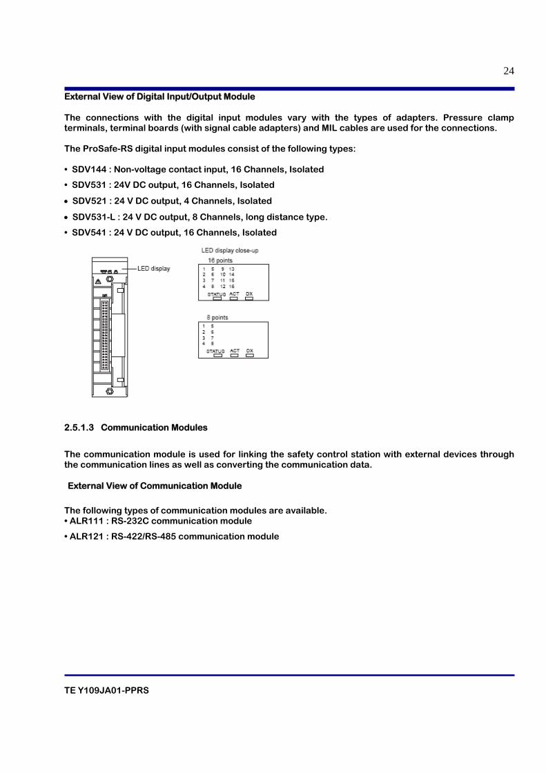
External View of Digital Input/Output Module The connections with the digital input modules vary with the types of adapters. Pressure clamp terminals, terminal boards (with signal cable adapters) and MIL cables are used for the connections. The ProSafe-RS digital input modules consist of the following types: • SDV144 : Non-voltage contact input, 16 Channels, Isolated
• SDV531 : 24V DC output, 16 Channels, Isolated
• SDV521 : 24 V DC output, 4 Channels, Isolated
• SDV531-L : 24 V DC output, 8 Channels, long distance type.
• SDV541 : 24 V DC output, 16 Channels, Isolated
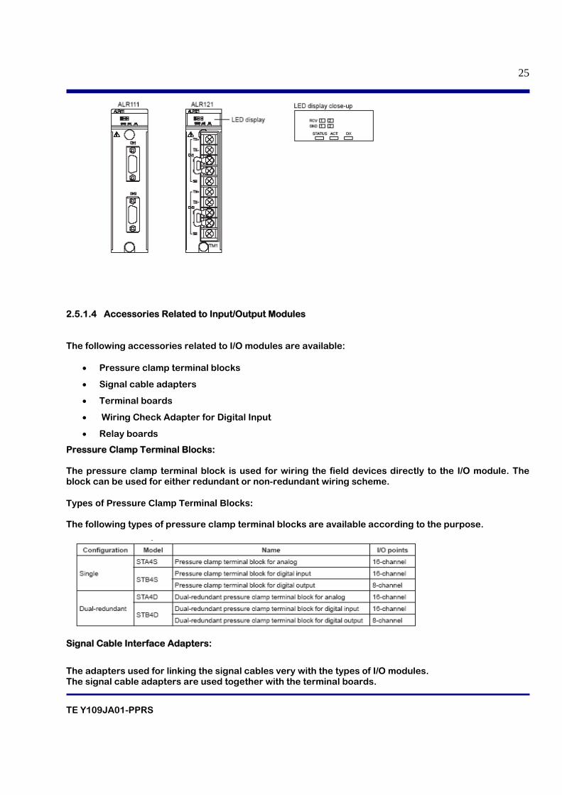
2.5.1.3 Communication Modules
The communication module is used for linking the safety control station with external devices through the communication lines as well as converting the communication data. External View of Communication Module
The following types of communication modules are available. • ALR111 : RS-232C communication module
• ALR121 : RS-422/RS-485 communication module
TE Y109JA01-PPRS
25
2.5.1.4 Accessories Related to Input/Output Modules
The following accessories related to I/O modules are available:
• Pressure clamp terminal blocks
• Signal cable adapters
• Terminal boards
• Wiring Check Adapter for Digital Input
• Relay boards
Pressure Clamp Terminal Blocks: The pressure clamp terminal block is used for wiring the field devices directly to the I/O module. The block can be used for either redundant or non-redundant wiring scheme. Types of Pressure Clamp Terminal Blocks: The following types of pressure clamp terminal blocks are available according to the purpose.
Signal Cable Interface Adapters:
The adapters used for linking the signal cables very with the types of I/O modules. The signal cable adapters are used together with the terminal boards.
TE Y109JA01-PPRS
26
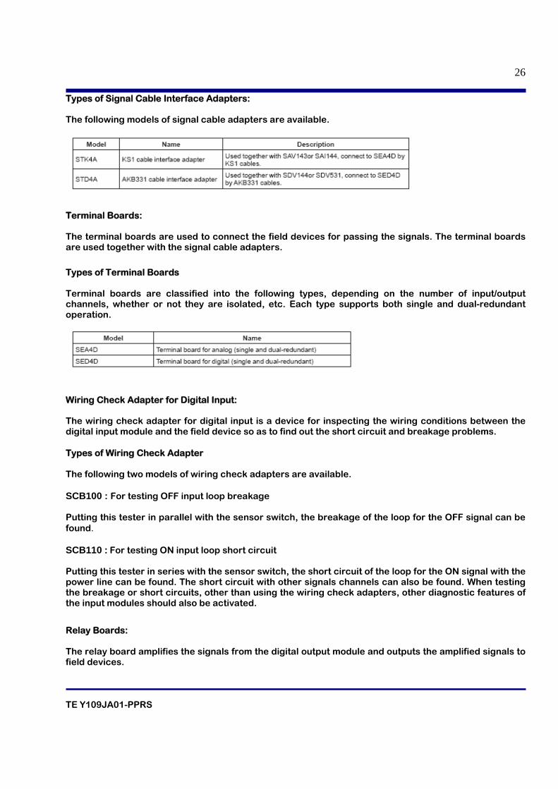
Types of Signal Cable Interface Adapters: The following models of signal cable adapters are available.
Terminal Boards: The terminal boards are used to connect the field devices for passing the signals. The terminal boards are used together with the signal cable adapters.
Types of Terminal Boards Terminal boards are classified into the following types, depending on the number of input/output channels, whether or not they are isolated, etc. Each type supports both single and dual-redundant operation.
Wiring Check Adapter for Digital Input: The wiring check adapter for digital input is a device for inspecting the wiring conditions between the digital input module and the field device so as to find out the short circuit and breakage problems. Types of Wiring Check Adapter The following two models of wiring check adapters are available. SCB100 : For testing OFF input loop breakage Putting this tester in parallel with the sensor switch, the breakage of the loop for the OFF signal can be found. SCB110 : For testing ON input loop short circuit Putting this tester in series with the sensor switch, the short circuit of the loop for the ON signal with the power line can be found. The short circuit with other signals channels can also be found. When testing the breakage or short circuits, other than using the wiring check adapters, other diagnostic features of the input modules should also be activated.
Relay Boards: The relay board amplifies the signals from the digital output module and outputs the amplified signals to field devices.
TE Y109JA01-PPRS
27
Types of Relay Boards The following models types of relay board are available with different numbers of contact outputs • SRM53D : 8x2 dry contact outputs (M4 terminals)
• SRM54D : 16x1 dry contact outputs (M4 terminals)
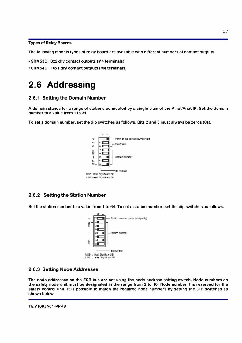
2.6 Addressing 2.6.1 Setting the Domain Number A domain stands for a range of stations connected by a single train of the V net/Vnet IP. Set the domain number to a value from 1 to 31. To set a domain number, set the dip switches as follows. Bits 2 and 3 must always be zeros (0s).
2.6.2 Setting the Station Number Set the station number to a value from 1 to 64. To set a station number, set the dip switches as follows.
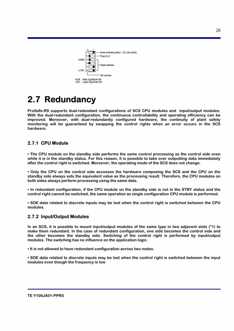
2.6.3 Setting Node Addresses The node addresses on the ESB bus are set using the node address setting switch. Node numbers on the safety node unit must be designated in the range from 2 to 10. Node number 1 is reserved for the safety control unit. It is possible to match the required node numbers by setting the DIP switches as shown below.
TE Y109JA01-PPRS
28
2.7 Redundancy ProSafe-RS supports dual-redundant configurations of SCS CPU modules and input/output modules. With the dual-redundant configuration, the continuous controllability and operating efficiency can be improved. Moreover, with dual-redundantly configured hardware, the continuity of plant safety monitoring will be guaranteed by swapping the control rights when an error occurs in the SCS hardware.
2.7.1 CPU Module • The CPU module on the standby side performs the same control processing as the control side even while it is in the standby status. For this reason, it is possible to take over outputting data immediately after the control right is switched. Moreover, the operating mode of the SCS does not change. • Only the CPU on the control side accesses the hardware composing the SCS and the CPU on the standby side always sets the equivalent value as the processing result. Therefore, the CPU modules on both sides always perform processing using the same data. • In redundant configuration, if the CPU module on the standby side is not in the STBY status and the control right cannot be switched, the same operation as single configuration CPU module is performed. • SOE data related to discrete inputs may be lost when the control right is switched between the CPU modules. 2.7.2 Input/Output Modules In an SCS, it is possible to mount input/output modules of the same type in two adjacent slots (*1) to make them redundant. In the case of redundant configuration, one side becomes the control side and the other becomes the standby side. Switching of the control right is performed by input/output modules. The switching has no influence on the application logic. • It is not allowed to have redundant configuration across two nodes. • SOE data related to discrete inputs may be lost when the control right is switched between the input modules even though the frequency is low
TE Y109JA01-PPRS
29
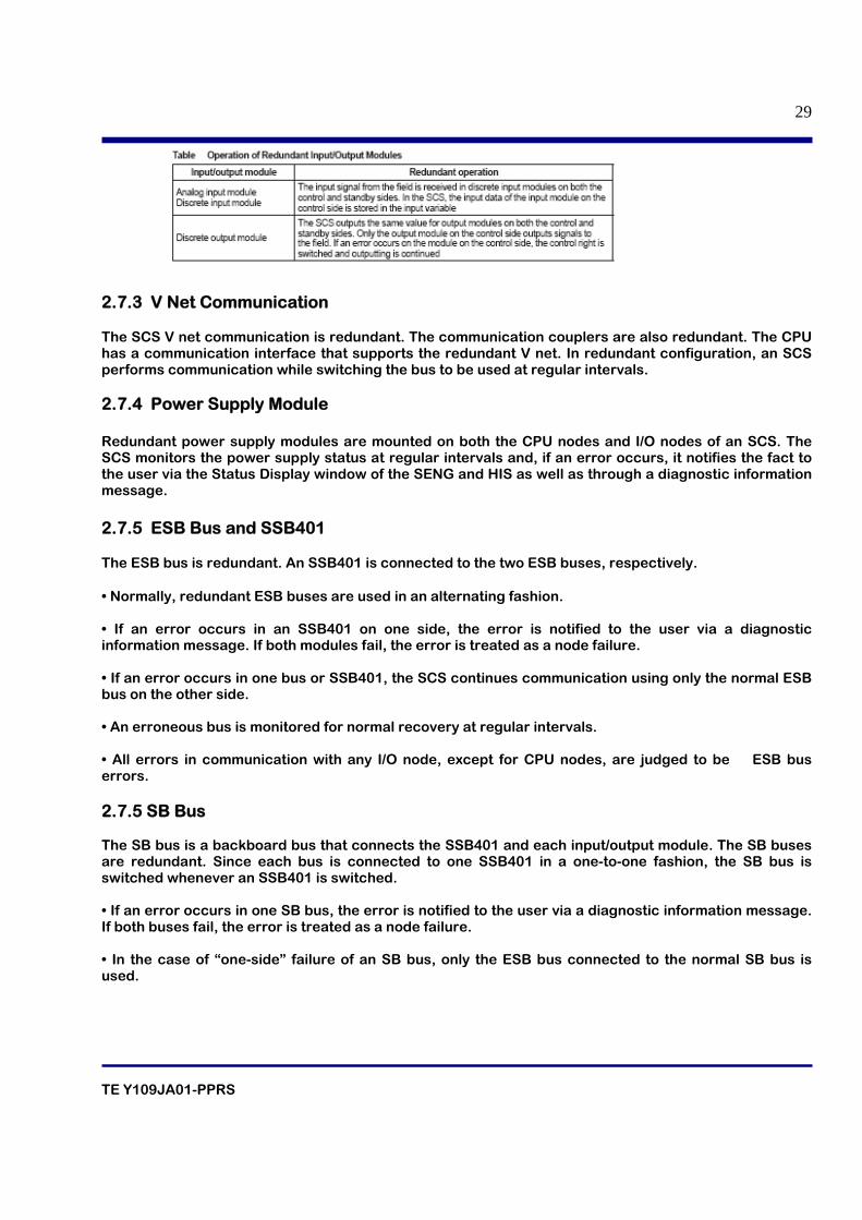
2.7.3 V Net Communication The SCS V net communication is redundant. The communication couplers are also redundant. The CPU has a communication interface that supports the redundant V net. In redundant configuration, an SCS performs communication while switching the bus to be used at regular intervals. 2.7.4 Power Supply Module Redundant power supply modules are mounted on both the CPU nodes and I/O nodes of an SCS. The SCS monitors the power supply status at regular intervals and, if an error occurs, it notifies the fact to the user via the Status Display window of the SENG and HIS as well as through a diagnostic information message. 2.7.5 ESB Bus and SSB401 The ESB bus is redundant. An SSB401 is connected to the two ESB buses, respectively. • Normally, redundant ESB buses are used in an alternating fashion. • If an error occurs in an SSB401 on one side, the error is notified to the user via a diagnostic information message. If both modules fail, the error is treated as a node failure. • If an error occurs in one bus or SSB401, the SCS continues communication using only the normal ESB bus on the other side. • An erroneous bus is monitored for normal recovery at regular intervals. • All errors in communication with any I/O node, except for CPU nodes, are judged to be ESB bus errors. 2.7.5 SB Bus The SB bus is a backboard bus that connects the SSB401 and each input/output module. The SB buses are redundant. Since each bus is connected to one SSB401 in a one-to-one fashion, the SB bus is switched whenever an SSB401 is switched. • If an error occurs in one SB bus, the error is notified to the user via a diagnostic information message. If both buses fail, the error is treated as a node failure. • In the case of “one-side” failure of an SB bus, only the ESB bus connected to the normal SB bus is used.
TE Y109JA01-PPRS
30
03. INTRODUCTION TO WORKBENCH
TE Y109JA01-PPRS
31
Table of contents
3.1 Introduction
3.2 Main Screens of workbench
3.2.1 Link Architecture
3.2.2 Hardware architecture
3.2.3 Dictionary
3.2.3.1 Variable Tree
3.2.3.2 Parameter Tree
3.2.3.3 Types Tree
3.2.3.4 Defined words Tree
3.2.4 I/O wiring
3.2.5 I/O Parameter Builder Setting
TE Y109JA01-PPRS
32
3.1 Introduction Prosafe-RS Workbench is the software program used to configure the Prosafe-RS system. The workbench also provides the user with the ability to:
• Transfer configuration to PLC
• Edit a project.
• View and update variables.
• Perform system troubleshooting.
• Produce documentation for a configuration.
Two languages are available for configuring the Prosafe-RS system.
• Function Block Diagrams.
• Ladder Diagrams.
• Structured Text Language
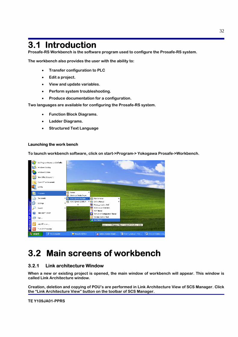
Launching the work bench To launch workbench software, click on start->Program-> Yokogawa Prosafe->Workbench.
3.2 Main screens of workbench 3.2.1 Link architecture Window
When a new or existing project is opened, the main window of workbench will appear. This window is called Link Architecture window. Creation, deletion and copying of POU’s are performed in Link Architecture View of SCS Manager. Click the “Link Architecture View” button on the toolbar of SCS Manager.
TE Y109JA01-PPRS
33
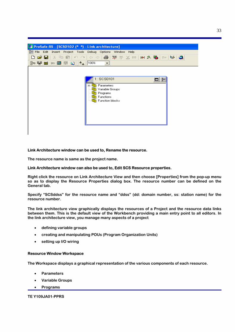
Link Architecture window can be used to, Rename the resource. The resource name is same as the project name. Link Architecture window can also be used to, Edit SCS Resource properties. Right click the resource on Link Architecture View and then choose [Properties] from the pop-up menu so as to display the Resource Properties dialog box. The resource number can be defined on the General tab. Specify “SCSddss” for the resource name and “ddss” (dd: domain number, ss: station name) for the resource number.
The link architecture view graphically displays the resources of a Project and the resource data links between them. This is the default view of the Workbench providing a main entry point to all editors. In the link architecture view, you manage many aspects of a project
• defining variable groups
• creating and manipulating POUs (Program Organization Units)
• setting up I/O wiring
Resource Window Workspace
The Workspace displays a graphical representation of the various components of each resource.
• Parameters
• Variable Groups
• Programs
TE Y109JA01-PPRS
34
• Functions
• Function Blocks
To expand / collapse any branch of the hierarchy
Editing Resource Properties
You need to define several properties at the resource level, intimately linked to targets (and their implementation). These properties determine the behavior of the programs and hardware, e.g., the type of code generated, the timing, and Hardware specific properties. These properties are:
• Resource Identification
• Compilation Options
• Run-time Settings
• Resource Network Parameters
Variable Bindings
Bindings are directional links, i.e., access paths, between variables located in different resources. One variable is referred to as the producing variable and the other as the consuming variable. The value stored in the producing variable is transferred to the consuming variable. The Workbench enables two types of bindings: internal bindings and external bindings. Internal bindings are between resources within the same project. External bindings are between resources belonging to different projects.
Variable Groups
Variables Groups provide a method of managing variables and logically sorting them within a resource. The variable groups are shown in the Variables Tree, their contents are defined within the Dictionary Variables grid. You can perform tasks to manage variable groups:
• Creating Variable Groups
• Opening Variable Groups
POUs (Program Organization Units)
A POU (Program Organization Unit) is a set of instructions written in one of the following languages: ST, FBD, and LD. POUs can be programs, functions, or function blocks.
You can perform many tasks when managing POUs:
• Creating POUs
• Manipulating POUs
You can create, i.e., add, POUs (programs, functions, and function blocks) in resources while in the link architecture view. You add POUs using the main menu or a contextual menu accessed by right-clicking the respective component (Program, Function, or Function Block) within a resource. After having created a POU, you can drag and drop it to a new position in its section, to another section, or to
TE Y109JA01-PPRS
35
another resource. POUs belonging to a same section must have different names. POU names must begin with a letter.
Controlling Access to POUs
You can control access to user-defined POUs using a password. When you set a project with the read-only access control, the resources and POUs making up the project are also set to the read-only mode except for those having individual access control. For instance, a POU having its own password remains locked and cannot be viewed without entering its password. When moving or copying a POU using its resources password, the POU retains this password.
The security state of a POU is indicated by its icon in the resource:
POU Icon
Security State
Yellow. The POU has no access control. All users have read and write access in the POU. In the dictionary view, local variables and parameters are visible and editable.
Red. The POU is locked. Users not having the POU password cannot access the POU; these users do not have read or write capabilities. In the dictionary view, local variables and parameters are visible but not editable.
Cyan. The POU is in read-only mode. Users not having the resource password can view the POU; these users do not have write capabilities. The read-only mode for the POU is inherited from the resource to which it belongs. In the dictionary view, local variables and parameters are visible but not editable.
Green. The POU is unlocked. User can access the POU; this user has read and writes capabilities. In the dictionary view, local variables and parameters are visible and editable.
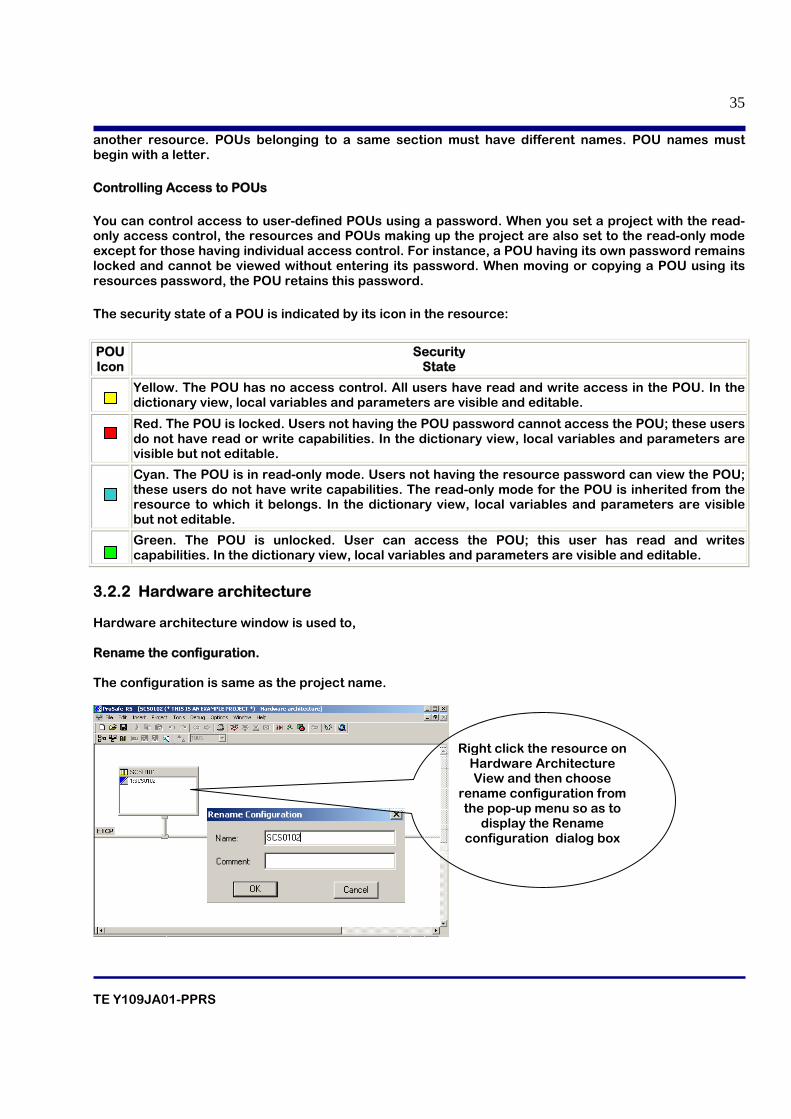
3.2.2 Hardware architecture Hardware architecture window is used to, Rename the configuration. The configuration is same as the project name.
Right click the resource on Hardware Architecture View and then choose
rename configuration from the pop-up menu so as to
display the Rename configuration dialog box
TE Y109JA01-PPRS
36
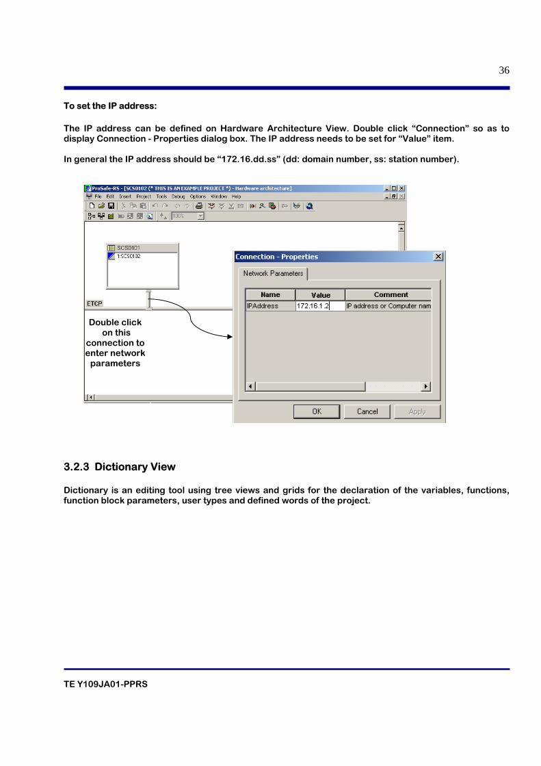
To set the IP address: The IP address can be defined on Hardware Architecture View. Double click “Connection” so as to display Connection - Properties dialog box. The IP address needs to be set for “Value” item. In general the IP address should be “172.16.dd.ss” (dd: domain number, ss: station number).
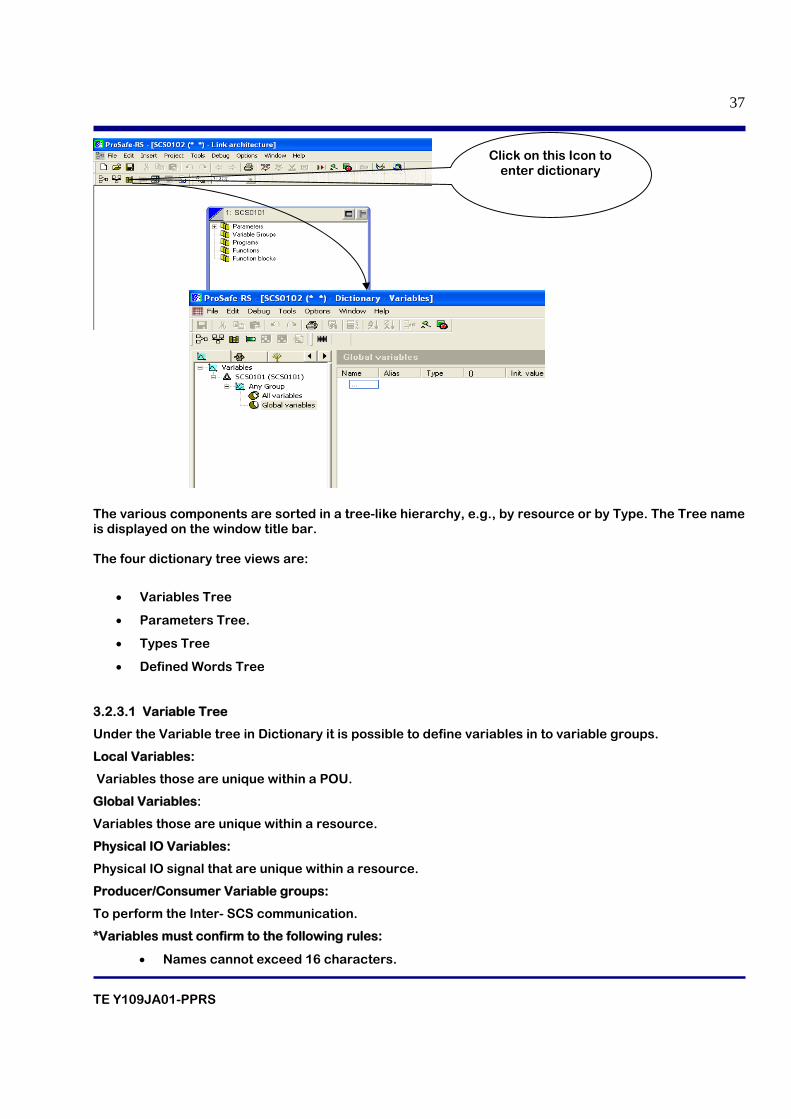
3.2.3 Dictionary View Dictionary is an editing tool using tree views and grids for the declaration of the variables, functions, function block parameters, user types and defined words of the project.
Double click on this
connection to enter network
parameters
TE Y109JA01-PPRS
37
The various components are sorted in a tree-like hierarchy, e.g., by resource or by Type. The Tree name is displayed on the window title bar. The four dictionary tree views are:
• Variables Tree
• Parameters Tree.
• Types Tree
• Defined Words Tree
3.2.3.1 Variable Tree
Under the Variable tree in Dictionary it is possible to define variables in to variable groups.
Local Variables:
Variables those are unique within a POU.
Global Variables:
Variables those are unique within a resource.
Physical IO Variables:
Physical IO signal that are unique within a resource.
Producer/Consumer Variable groups:
To perform the Inter- SCS communication.
*Variables must confirm to the following rules:
• Names cannot exceed 16 characters.
Click on this Icon to enter dictionary
TE Y109JA01-PPRS
38
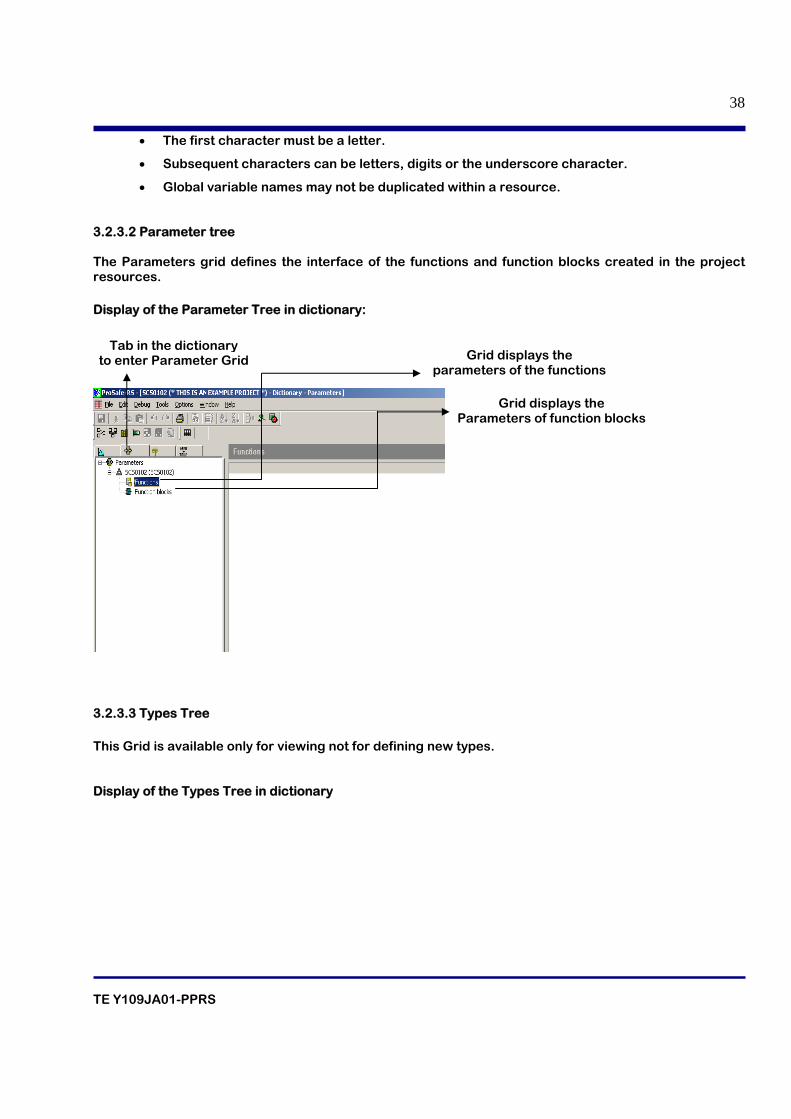
• The first character must be a letter.
• Subsequent characters can be letters, digits or the underscore character.
• Global variable names may not be duplicated within a resource.
3.2.3.2 Parameter tree The Parameters grid defines the interface of the functions and function blocks created in the project resources. Display of the Parameter Tree in dictionary:
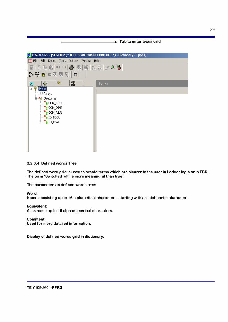
3.2.3.3 Types Tree This Grid is available only for viewing not for defining new types. Display of the Types Tree in dictionary
Grid displays the parameters of the functions
Grid displays the Parameters of function blocks
Tab in the dictionary to enter Parameter Grid
TE Y109JA01-PPRS
39
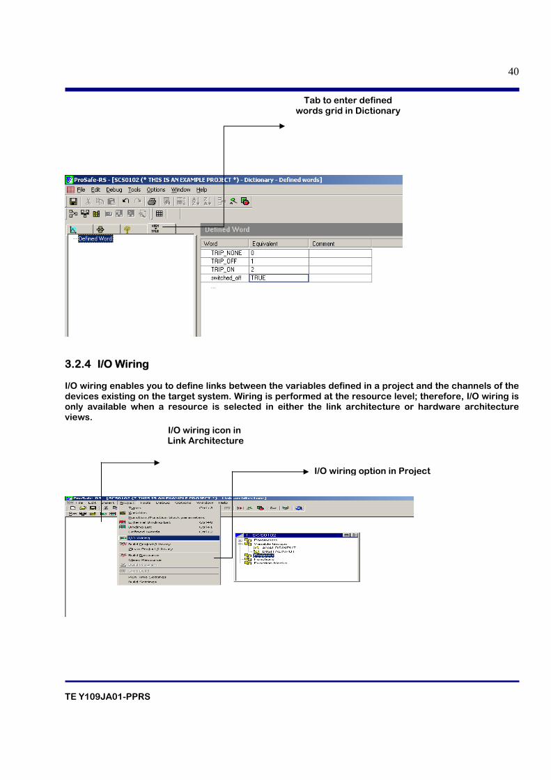
3.2.3.4 Defined words Tree The defined word grid is used to create terms which are clearer to the user in Ladder logic or in FBD. The term ‘Switched_off’ is more meaningful than true. The parameters in defined words tree: Word: Name consisting up to 16 alphabetical characters, starting with an alphabetic character. Equivalent: Alias name up to 16 alphanumerical characters. Comment: Used for more detailed information. Display of defined words grid in dictionary.
Tab to enter types grid
TE Y109JA01-PPRS
40
3.2.4 I/O Wiring I/O wiring enables you to define links between the variables defined in a project and the channels of the devices existing on the target system. Wiring is performed at the resource level; therefore, I/O wiring is only available when a resource is selected in either the link architecture or hardware architecture views.
Tab to enter defined words grid in Dictionary
I/O wiring icon in Link Architecture
I/O wiring option in Project
TE Y109JA01-PPRS
41
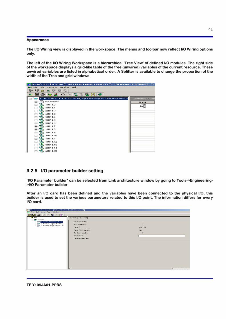
Appearance
The I/O Wiring view is displayed in the workspace. The menus and toolbar now reflect I/O Wiring options only.
The left of the I/O Wiring Workspace is a hierarchical 'Tree View' of defined I/O modules. The right side of the workspace displays a grid-like table of the free (unwired) variables of the current resource. These unwired variables are listed in alphabetical order. A Splitter is available to change the proportion of the width of the Tree and grid windows.
3.2.5 I/O parameter builder setting. ‘I/O Parameter builder’ can be selected from Link architecture window by going to Tools->Engineering->I/O Parameter builder. After an I/O card has been defined and the variables have been connected to the physical I/O, this builder is used to set the various parameters related to this I/O point. The information differs for every I/O card.
TE Y109JA01-PPRS
42
4. ENGINEERING IN PROSAFE-RS
TE Y109JA01-PPRS
43
Table of contents 4.1 Procedure for Engineering
4.2 Classification of SCS Application
4.3 Restriction on System configuration
4.4 Restrictions on Installation of Hardware
4.5 Capacity of SCS Applications
4.6 Performance and Scan Period in SCS
4.7 Time Synchronization
4.8 Project Creation
4.9 Creation of Variables in Dictionary
4.9.1 Creation of Variable groups
4.9.2 Creation of Analog I/O variables in dictionary
4.9.3 Creation of Digital I/O variables in dictionary
4.9.4 Creation of internal variable in dictionary
4.10 Creation of I/O cards in I/O wiring view
TE Y109JA01-PPRS
44
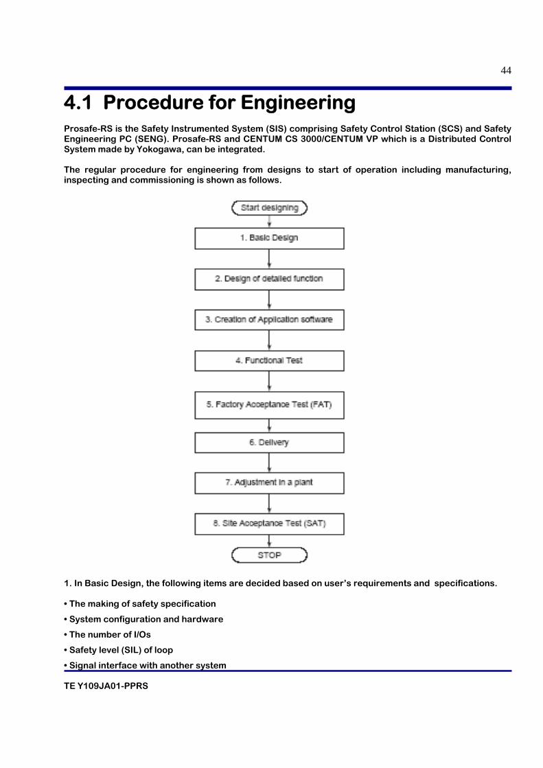
4.1 Procedure for Engineering Prosafe-RS is the Safety Instrumented System (SIS) comprising Safety Control Station (SCS) and Safety Engineering PC (SENG). Prosafe-RS and CENTUM CS 3000/CENTUM VP which is a Distributed Control System made by Yokogawa, can be integrated. The regular procedure for engineering from designs to start of operation including manufacturing, inspecting and commissioning is shown as follows.
1. In Basic Design, the following items are decided based on user’s requirements and specifications. • The making of safety specification
• System configuration and hardware
• The number of I/Os
• Safety level (SIL) of loop
• Signal interface with another system
TE Y109JA01-PPRS
45
The following documents are made as a result of these works.
• Diagrams of the system structure
• Hardware specifications
• I/O lists
• System basic design document
• List of interface with other systems
2. Based on the user’s requirements and specification, functional specifications are made. Detailed logic like shutdown logic is included in the functional specifications.
3. ProSafe-RS projects and applications are created on a PC installing the SENG Function. 4. Functions of the created application are checked. After making a document about the Test
Specification, usually testing of functions is conducted in the following order. 1) Desk test The created applications are checked with self documents on the desk. 2) Unit test-1 Created application logics are verified. SCS simulation and Logic simulation test on SENG can be used for this verification. 3) Unit test-2 In the target test using SCS, the overall logic etc. are verified. 4) Integration test
The integrated final test is conducted on the SCS target. Before the test, it is required to provide an environment, where SCS can be used, in combination with panel, console, a host computer and other subsystems. The testing for system failure such as hardware failure is also conducted.
5. Hardware and software Factory Acceptance Test (FAT) is conducted in the presence of users. 6. Hardware and software which the user has confirmed in FAT are delivered. 7. Hardware and software which are installed in the plant are adjusted. 8. The Site Acceptance Test (SAT) is conducted to hand over the system to the user.
4.2 Classification of SCS Application Below are the applications that are running on a SCS. • Safety Application This is an application which executes safety functions. The safety application includes application logic written in the language conforming to the IEC 61131-3 standards. The following programming languages defined in IEC 61131-3 are available for SCS.
- Function Block Diagram (FBD)
- Ladder Diagram (LD)
- Structured Text (ST)
TE Y109JA01-PPRS
46
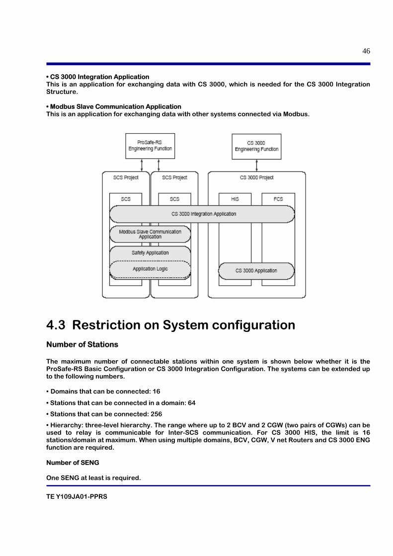
• CS 3000 Integration Application This is an application for exchanging data with CS 3000, which is needed for the CS 3000 Integration Structure. • Modbus Slave Communication Application This is an application for exchanging data with other systems connected via Modbus.
4.3 Restriction on System configuration Number of Stations The maximum number of connectable stations within one system is shown below whether it is the ProSafe-RS Basic Configuration or CS 3000 Integration Configuration. The systems can be extended up to the following numbers. • Domains that can be connected: 16
• Stations that can be connected in a domain: 64
• Stations that can be connected: 256
• Hierarchy: three-level hierarchy. The range where up to 2 BCV and 2 CGW (two pairs of CGWs) can be used to relay is communicable for Inter-SCS communication. For CS 3000 HIS, the limit is 16 stations/domain at maximum. When using multiple domains, BCV, CGW, V net Routers and CS 3000 ENG function are required. Number of SENG One SENG at least is required.
TE Y109JA01-PPRS
47
Number of SCS The number of stations should be within the limit. Connect Vnet/IP domains on each Bus with a Layer 3 switch (L3SW). This also requires the CS 3000/Centum VP ENG function. Vnet/IP Domains Connection Specifications • Number of connectable domains: 16 (Total of Vnet/IP domains and V net domains) • Number of Layer 3 switches (L3SW) allowed: 15 levels Connection Specifications in a Vnet/IP Domain • Number of connectable Vnet/IP stations: Max. 64 (Vnet/IP stations including V net routers) • General-purpose Ethernet communication devices: Max. 124 (PCs, Routers, etc.)
• Distance between stations in a Vnet/IP domain: Max. 40 km
• Distance between Layer 2 switch and a station: Max. 100 m (for Unshielded Twisted Pair (UTP)); Max. 5 km (for fiber-optic cable) • Distance between Layer 2 switches: Max. 5 km (for fiber-optic cable)
• Number of connectable Layer 2 switches in a domain: Max. 7 per each Bus. (Multilayer by cascade connection allowed)
4.4 Restrictions on Installation of Hardware There are the following restrictions on installation of hardware in SCS. • SCS can connect the CPU node to up to 9 I/O nodes. • When expanding I/O, SEC401s are installed to slots 7 and 8 of the CPU node. In the absence of expandable I.O nodes, I/O modules can be installed to these slots. • When configuring I/O modules in redundant configuration, install them to any of the following slots in pairs: 1 and 2, 3 and 4, 5 and 6, 7 and 8 • For installation of I/O modules, there are two more limitations other than the above restrictions. One is imposed by electric capacity and another is imposed by ambient temperature conditions (60°C~70°C) for operation. • The Optical ESB Bus Repeater modules must be mounted within the specified operating temperature range. • Up to four serial communication modules (ALR111 and ALR121) per SCS can be installed (two pairs in redundant configuration) as subsystem communication master modules and up to two modules can be installed as Modbus slave communication modules. Note that it is not allowed to perform both subsystem communication and Modbus slave communication using the same serial communication module.
TE Y109JA01-PPRS
48
• With SCS-IP, you cannot install the serial communication modules for Modbus slave communication (that is, ALR111 and ALR121) to I/O nodes that are located further than 5 km, using the an optical ESB bus repeater module. • Operating temperature is different between Safety Control unit for Vnet/IP and Safety Control unit for V net.
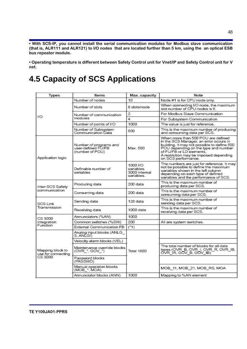
4.5 Capacity of SCS Applications
TE Y109JA01-PPRS
49
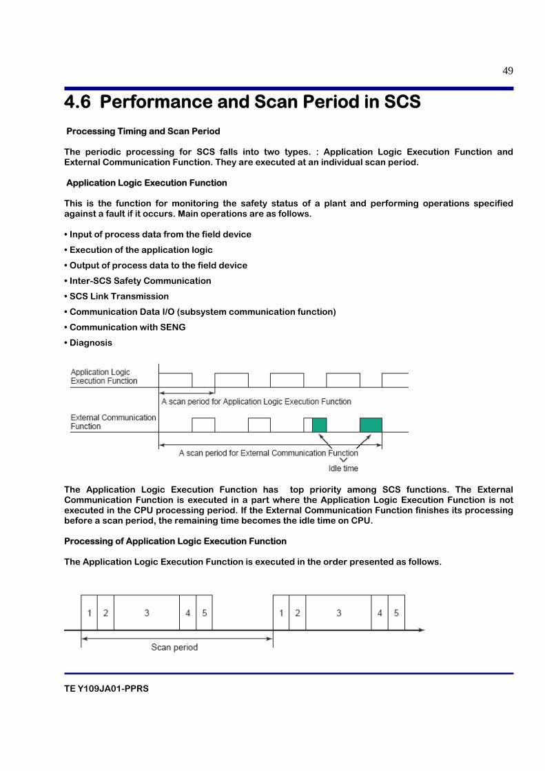
4.6 Performance and Scan Period in SCS Processing Timing and Scan Period The periodic processing for SCS falls into two types. : Application Logic Execution Function and External Communication Function. They are executed at an individual scan period. Application Logic Execution Function This is the function for monitoring the safety status of a plant and performing operations specified against a fault if it occurs. Main operations are as follows. • Input of process data from the field device
• Execution of the application logic
• Output of process data to the field device
• Inter-SCS Safety Communication
• SCS Link Transmission
• Communication Data I/O (subsystem communication function)
• Communication with SENG
• Diagnosis
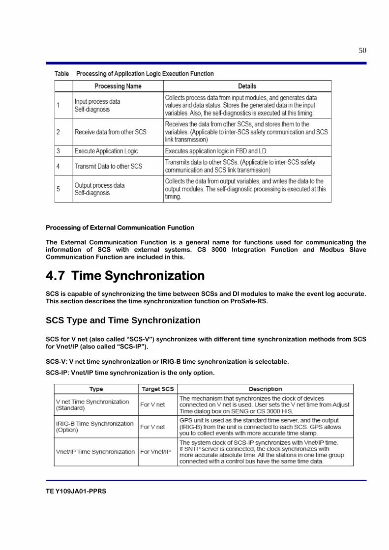
The Application Logic Execution Function has top priority among SCS functions. The External Communication Function is executed in a part where the Application Logic Execution Function is not executed in the CPU processing period. If the External Communication Function finishes its processing before a scan period, the remaining time becomes the idle time on CPU. Processing of Application Logic Execution Function The Application Logic Execution Function is executed in the order presented as follows.
TE Y109JA01-PPRS
50
Processing of External Communication Function The External Communication Function is a general name for functions used for communicating the information of SCS with external systems. CS 3000 Integration Function and Modbus Slave Communication Function are included in this.
4.7 Time Synchronization SCS is capable of synchronizing the time between SCSs and DI modules to make the event log accurate. This section describes the time synchronization function on ProSafe-RS.
SCS Type and Time Synchronization SCS for V net (also called “SCS-V”) synchronizes with different time synchronization methods from SCS for Vnet/IP (also called “SCS-IP”). SCS-V: V net time synchronization or IRIG-B time synchronization is selectable.
SCS-IP: Vnet/IP time synchronization is the only option.
TE Y109JA01-PPRS
51
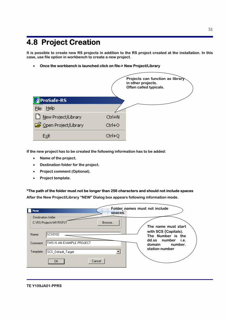
4.8 Project Creation It is possible to create new RS projects in addition to the RS project created at the installation. In this case, use file option in workbench to create a new project.
• Once the workbench is launched click on file-> New Project/Library
If the new project has to be created the following information has to be added:
• Name of the project.
• Destination folder for the project.
• Project comment (Optional).
• Project template.
*The path of the folder must not be longer than 256 characters and should not include spaces
After the New Project/Library “NEW” Dialog box appears following information mode.
Projects can function as library in other projects. Often called typicals.
Folder names must not include spaces.
The name must start with SCS (Capitals). The Number is the dd.ss number i.e. domain number. station number
TE Y109JA01-PPRS
52
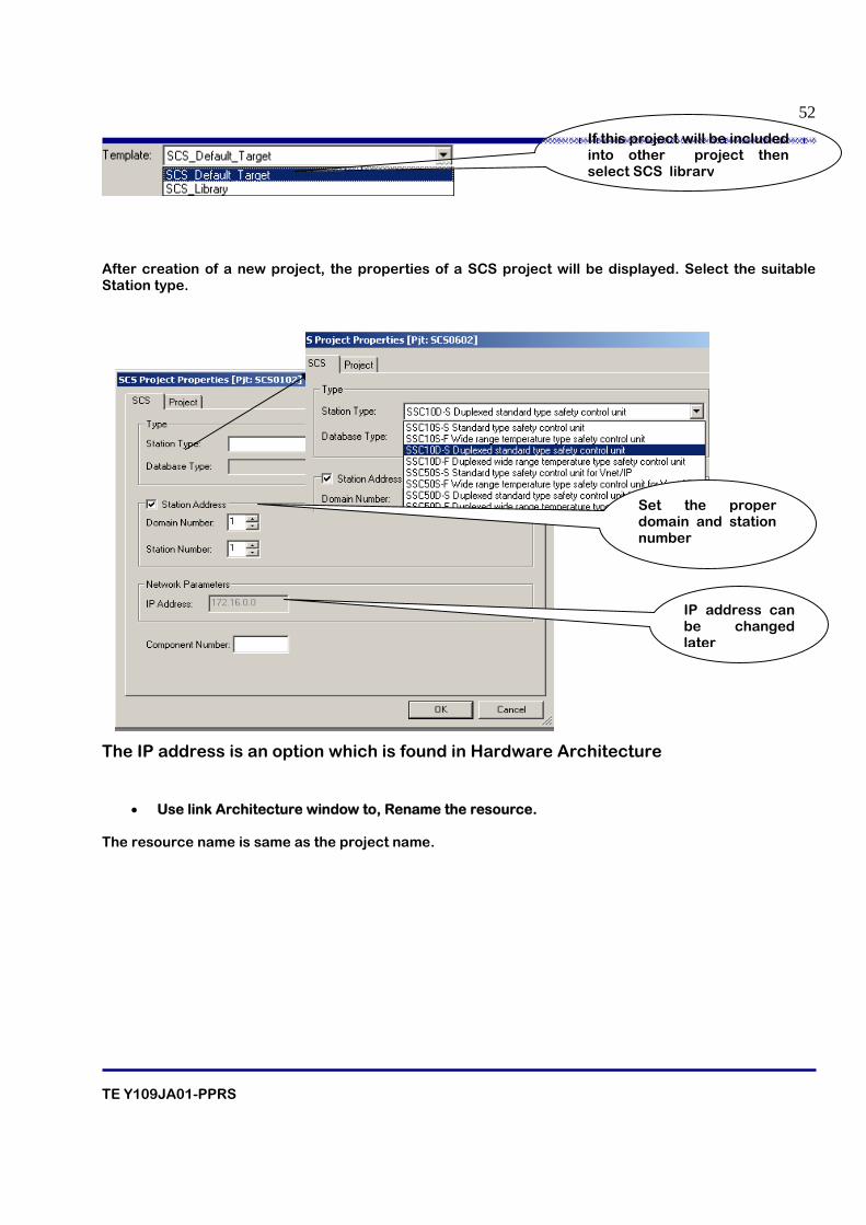
After creation of a new project, the properties of a SCS project will be displayed. Select the suitable Station type.
The IP address is an option which is found in Hardware Architecture
• Use link Architecture window to, Rename the resource. The resource name is same as the project name.
If this project will be included into other project then select SCS library
Set the proper domain and station number
IP address can be changed later
TE Y109JA01-PPRS
53
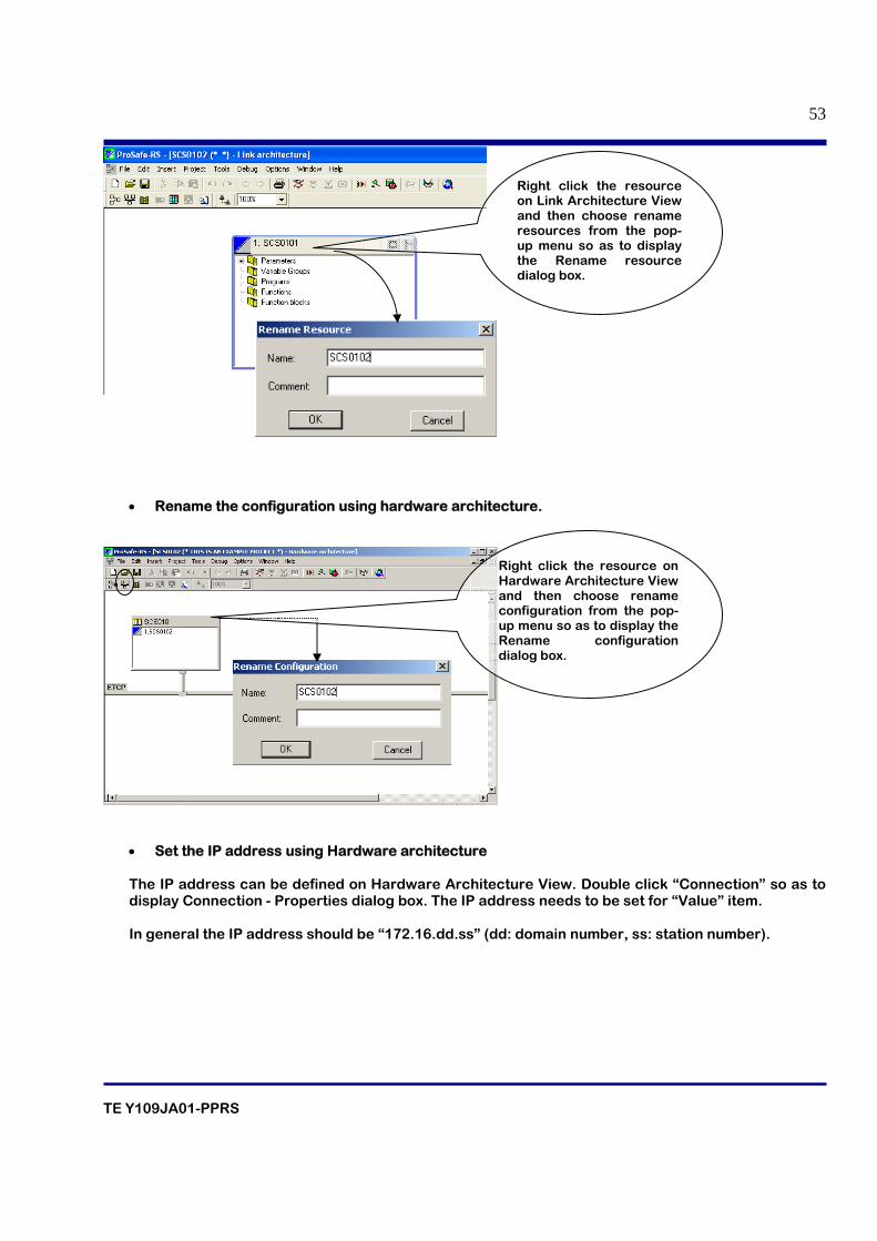
• Rename the configuration using hardware architecture.
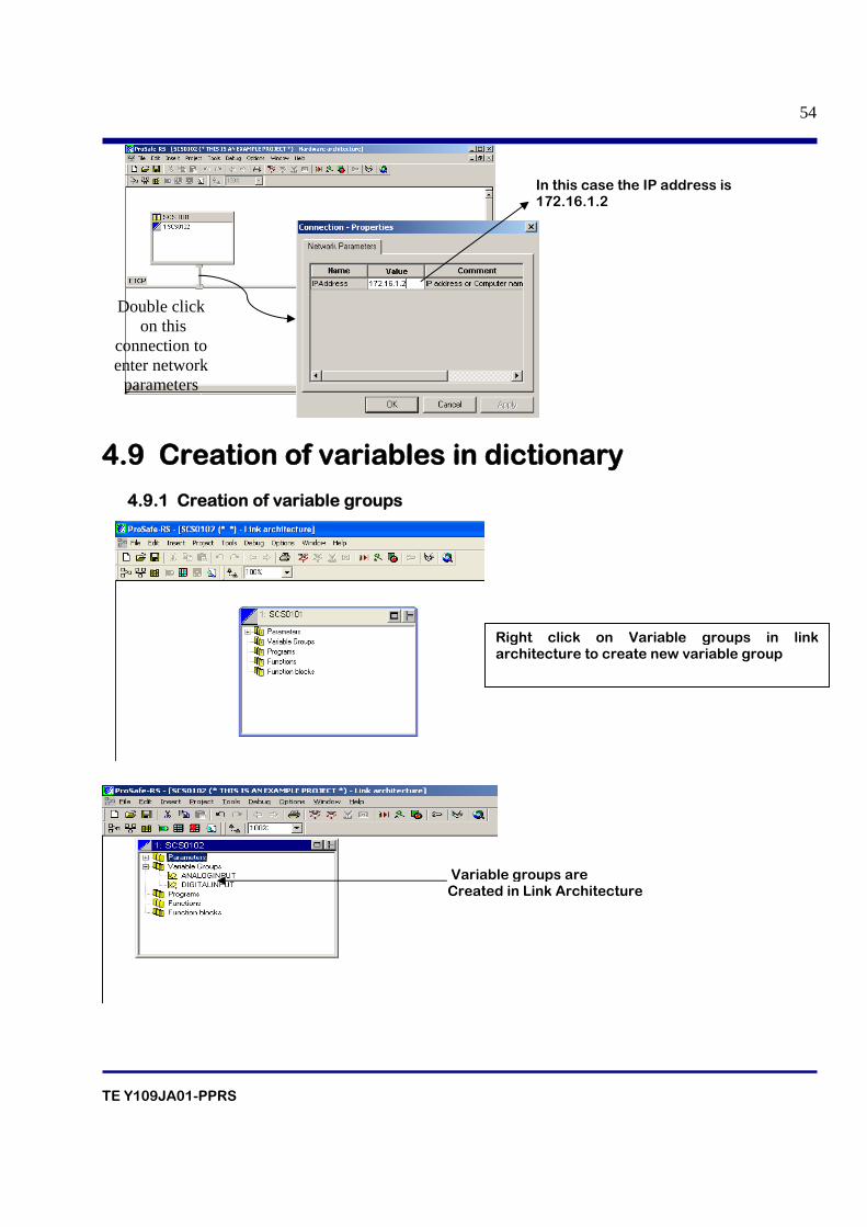
• Set the IP address using Hardware architecture The IP address can be defined on Hardware Architecture View. Double click “Connection” so as to display Connection - Properties dialog box. The IP address needs to be set for “Value” item. In general the IP address should be “172.16.dd.ss” (dd: domain number, ss: station number).
Right click the resource on Link Architecture View and then choose rename resources from the pop-up menu so as to display the Rename resource dialog box.
Right click the resource on Hardware Architecture View and then choose rename configuration from the pop-up menu so as to display the Rename configuration dialog box.
TE Y109JA01-PPRS
54
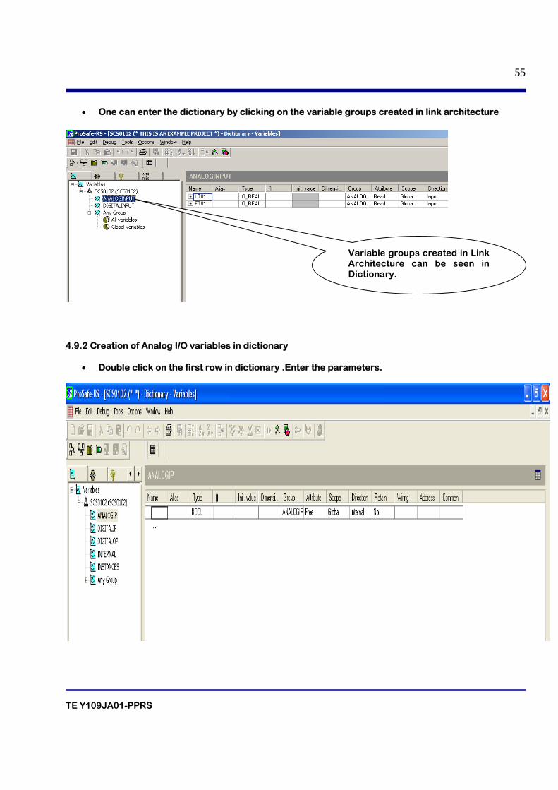
4.9 Creation of variables in dictionary 4.9.1 Creation of variable groups
In this case the IP address is 172.16.1.2
Double click on this
connection to enter network
parameters
Right click on Variable groups in link architecture to create new variable group
Variable groups are Created in Link Architecture
TE Y109JA01-PPRS
55
• One can enter the dictionary by clicking on the variable groups created in link architecture
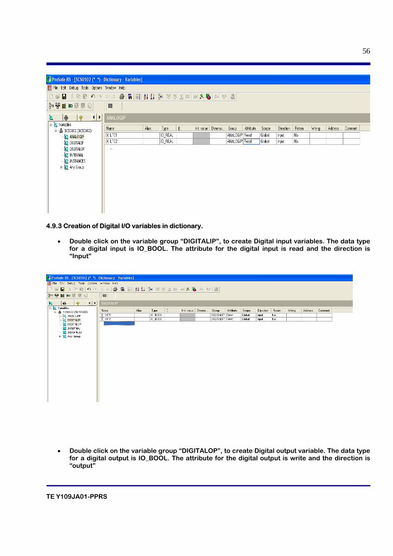
4.9.2 Creation of Analog I/O variables in dictionary
• Double click on the first row in dictionary .Enter the parameters.
Variable groups created in Link Architecture can be seen in Dictionary.
TE Y109JA01-PPRS
56
4.9.3 Creation of Digital I/O variables in dictionary.
• Double click on the variable group “DIGITALIP”, to create Digital input variables. The data type for a digital input is IO_BOOL. The attribute for the digital input is read and the direction is “Input”
• Double click on the variable group “DIGITALOP”, to create Digital output variable. The data type for a digital output is IO_BOOL. The attribute for the digital output is write and the direction is “output”
TE Y109JA01-PPRS
57
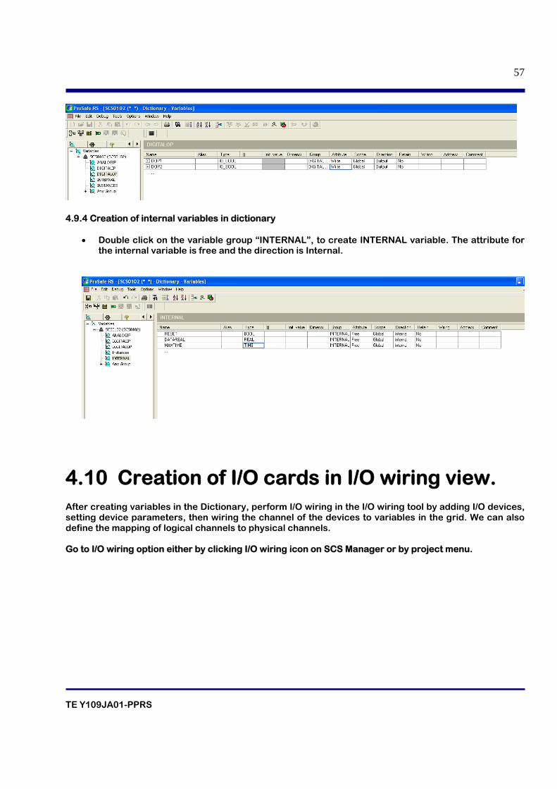
4.9.4 Creation of internal variables in dictionary
• Double click on the variable group “INTERNAL”, to create INTERNAL variable. The attribute for the internal variable is free and the direction is Internal.
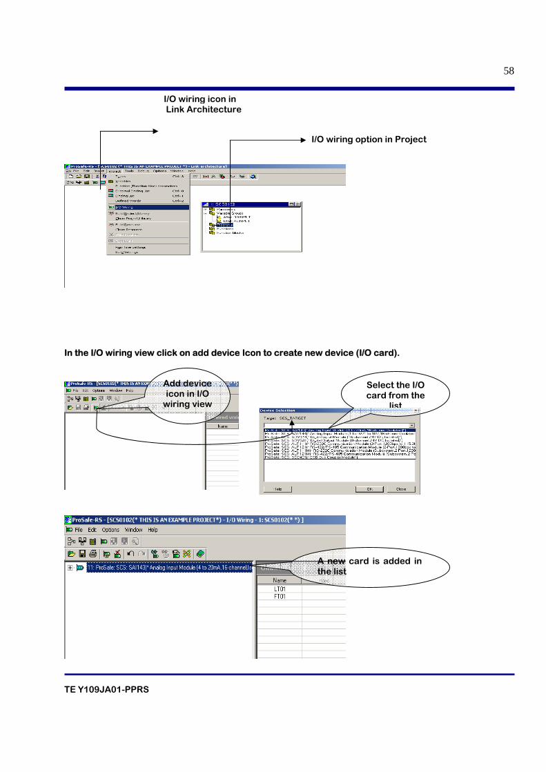
4.10 Creation of I/O cards in I/O wiring view.
After creating variables in the Dictionary, perform I/O wiring in the I/O wiring tool by adding I/O devices, setting device parameters, then wiring the channel of the devices to variables in the grid. We can also define the mapping of logical channels to physical channels. Go to I/O wiring option either by clicking I/O wiring icon on SCS Manager or by project menu.
TE Y109JA01-PPRS
58
In the I/O wiring view click on add device Icon to create new device (I/O card).
A new card is added in the list
I/O wiring icon in Link Architecture
I/O wiring option in Project
Add device icon in I/O
wiring view
Select the I/O card from the
list
TE Y109JA01-PPRS
59
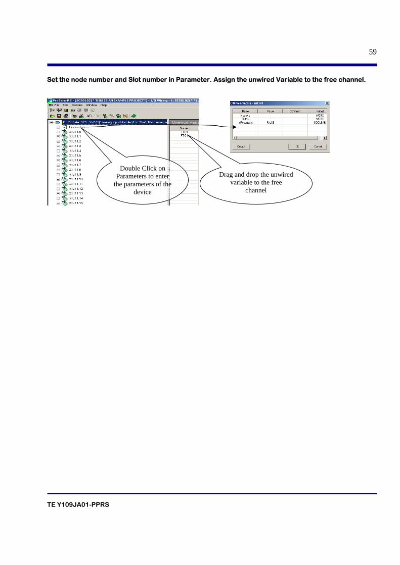
Set the node number and Slot number in Parameter. Assign the unwired Variable to the free channel.
Double Click on Parameters to enter
the parameters of the device
Drag and drop the unwired variable to the free
channel
TE Y109JA01-PPRS
60
5. SECURITY
TE Y109JA01-PPRS
61
Table of contents 5.1 Overview of ProSafe-RS Security
5.1.1 Online Level
5.1.2 Offline Level
5.2 Security of SCS
5.2.1 Procedure to change the Password
5.2.2 Changing the security level
5.3 Security of SCS Maintenance Support Tool 5.4 Security of SCS Database
5.4.1 Setting Password for the SCS Project
5.4.2 Setting Password for Each POU
TE Y109JA01-PPRS
62
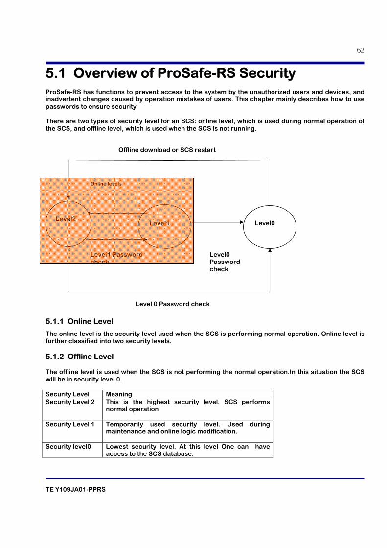
5.1 Overview of ProSafe-RS Security ProSafe-RS has functions to prevent access to the system by the unauthorized users and devices, and inadvertent changes caused by operation mistakes of users. This chapter mainly describes how to use passwords to ensure security There are two types of security level for an SCS: online level, which is used during normal operation of the SCS, and offline level, which is used when the SCS is not running.
5.1.1 Online Level
The online level is the security level used when the SCS is performing normal operation. Online level is further classified into two security levels. 5.1.2 Offline Level The offline level is used when the SCS is not performing the normal operation.In this situation the SCS will be in security level 0. Security Level Meaning Security Level 2 This is the highest security level. SCS performs
normal operation
Security Level 1 Temporarily used security level. Used during maintenance and online logic modification.
Security level0 Lowest security level. At this level One can have access to the SCS database.
Level1
Level0
Online levels
Level1 Password check
Level0 Password check
Level2
Offline download or SCS restart
Level 0 Password check
TE Y109JA01-PPRS
63
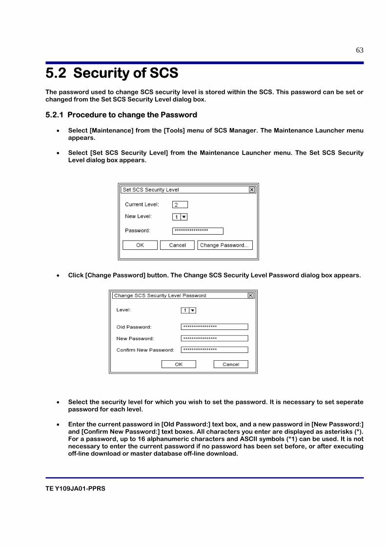
5.2 Security of SCS The password used to change SCS security level is stored within the SCS. This password can be set or changed from the Set SCS Security Level dialog box. 5.2.1 Procedure to change the Password
• Select [Maintenance] from the [Tools] menu of SCS Manager. The Maintenance Launcher menu appears.
• Select [Set SCS Security Level] from the Maintenance Launcher menu. The Set SCS Security
Level dialog box appears.
• Click [Change Password] button. The Change SCS Security Level Password dialog box appears.
• Select the security level for which you wish to set the password. It is necessary to set seperate
password for each level. • Enter the current password in [Old Password:] text box, and a new password in [New Password:]
and [Confirm New Password:] text boxes. All characters you enter are displayed as asterisks (*). For a password, up to 16 alphanumeric characters and ASCII symbols (*1) can be used. It is not necessary to enter the current password if no password has been set before, or after executing off-line download or master database off-line download.
TE Y109JA01-PPRS
64
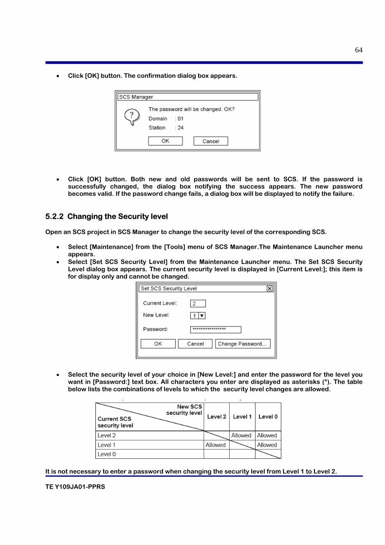
• Click [OK] button. The confirmation dialog box appears.
• Click [OK] button. Both new and old passwords will be sent to SCS. If the password is successfully changed, the dialog box notifying the success appears. The new password becomes valid. If the password change fails, a dialog box will be displayed to notify the failure.
5.2.2 Changing the Security level Open an SCS project in SCS Manager to change the security level of the corresponding SCS.
• Select [Maintenance] from the [Tools] menu of SCS Manager.The Maintenance Launcher menu appears.
• Select [Set SCS Security Level] from the Maintenance Launcher menu. The Set SCS Security Level dialog box appears. The current security level is displayed in [Current Level:]; this item is for display only and cannot be changed.
• Select the security level of your choice in [New Level:] and enter the password for the level you want in [Password:] text box. All characters you enter are displayed as asterisks (*). The table below lists the combinations of levels to which the security level changes are allowed.
It is not necessary to enter a password when changing the security level from Level 1 to Level 2.
TE Y109JA01-PPRS
65
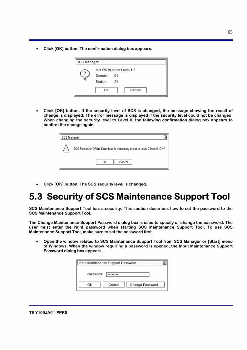
• Click [OK] button. The confirmation dialog box appears.
• Click [OK] button. If the security level of SCS is changed, the message showing the result of change is displayed. The error message is displayed if the security level could not be changed. When changing the security level to Level 0, the following confirmation dialog box appears to confirm the change again.
• Click [OK] button. The SCS security level is changed.
5.3 Security of SCS Maintenance Support Tool SCS Maintenance Support Tool has a security. This section describes how to set the password to the SCS Maintenance Support Tool. The Change Maintenance Support Password dialog box is used to specify or change the password. The user must enter the right password when starting SCS Maintenance Support Tool. To use SCS Maintenance Support Tool, make sure to set the password first.
• Open the window related to SCS Maintenance Support Tool from SCS Manager or [Start] menu of Windows. When the window requiring a password is opened, the Input Maintenance Support Password dialog box appears.
TE Y109JA01-PPRS
66
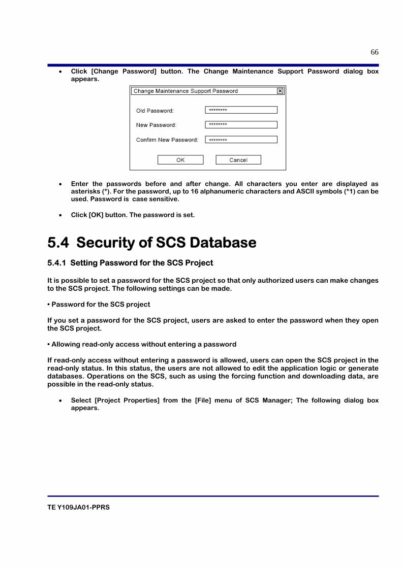
• Click [Change Password] button. The Change Maintenance Support Password dialog box appears.
• Enter the passwords before and after change. All characters you enter are displayed as asterisks (*). For the password, up to 16 alphanumeric characters and ASCII symbols (*1) can be used. Password is case sensitive.
• Click [OK] button. The password is set.
5.4 Security of SCS Database 5.4.1 Setting Password for the SCS Project It is possible to set a password for the SCS project so that only authorized users can make changes to the SCS project. The following settings can be made. • Password for the SCS project If you set a password for the SCS project, users are asked to enter the password when they open the SCS project. • Allowing read-only access without entering a password If read-only access without entering a password is allowed, users can open the SCS project in the read-only status. In this status, the users are not allowed to edit the application logic or generate databases. Operations on the SCS, such as using the forcing function and downloading data, are possible in the read-only status.
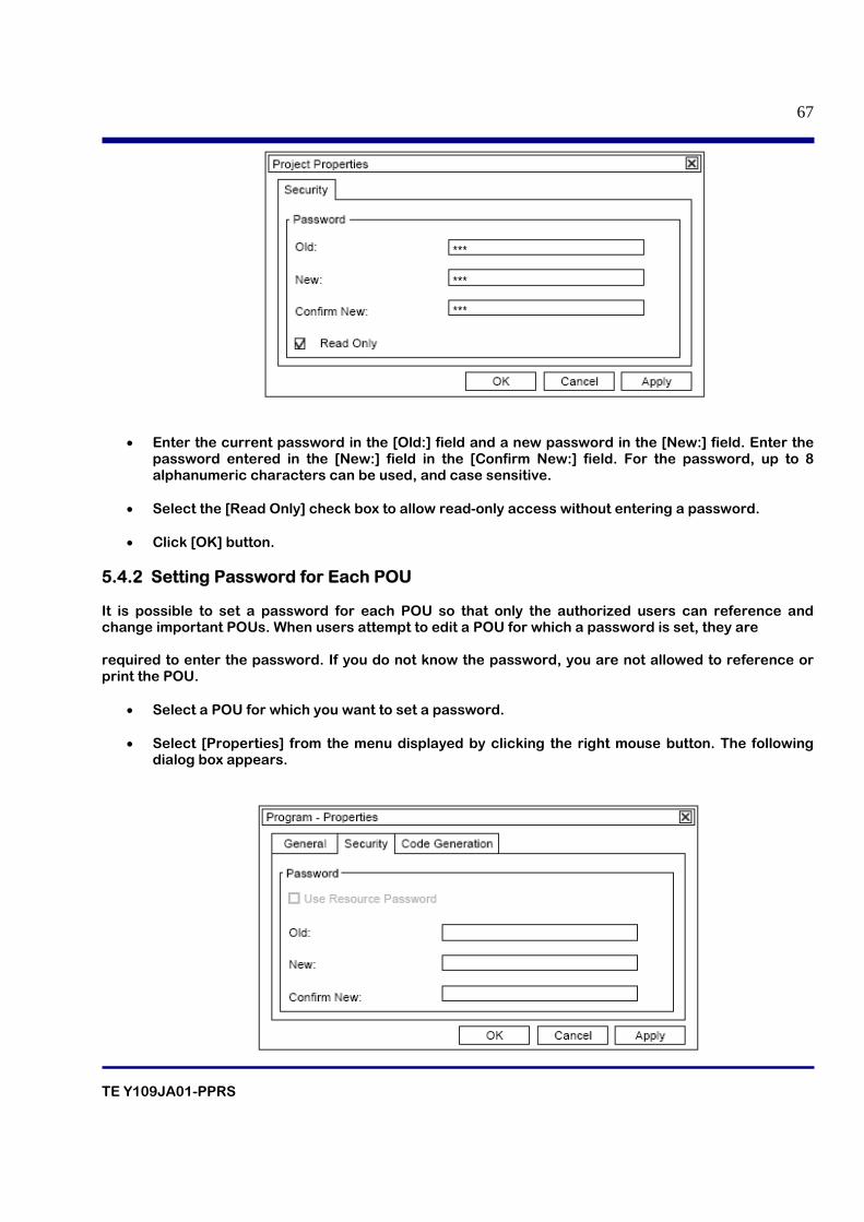
• Select [Project Properties] from the [File] menu of SCS Manager; The following dialog box appears.
TE Y109JA01-PPRS
67
• Enter the current password in the [Old:] field and a new password in the [New:] field. Enter the password entered in the [New:] field in the [Confirm New:] field. For the password, up to 8 alphanumeric characters can be used, and case sensitive.
• Select the [Read Only] check box to allow read-only access without entering a password.
• Click [OK] button.
5.4.2 Setting Password for Each POU It is possible to set a password for each POU so that only the authorized users can reference and change important POUs. When users attempt to edit a POU for which a password is set, they are required to enter the password. If you do not know the password, you are not allowed to reference or print the POU.
• Select a POU for which you want to set a password. • Select [Properties] from the menu displayed by clicking the right mouse button. The following
dialog box appears.

TE Y109JA01-PPRS
68
• Enter the current password in the [Old:] field and a new password in the [New:] field.Enter the
password entered in the [New:] field in the [Confirm New:] field. For the password, up to 8 alphanumeric characters can be used, and case sensitive.
• Click [OK] button.

TE Y109JA01-PPRS
69
6. DOWNLOADING
TE Y109JA01-PPRS
70
Table of contents
6.1 What is Downloading?
6.2 Overview and Types of Downloading
6.3 Downloading Functions and Databases 6.4 Downloading and SCS security level 6.5 Offline download
6.5.1 Downloaded Items
6.5.2 Procedure for offline Download
6.5.3 Integrity analyzer
6.5.4 Cross reference analyzer
6.6 Online change Download
6.6.1 Procedure for online change Download
6.7 Master database offline download
6.7.1 Procedure for master database offline Download
6.8 List of applicable items for online change
TE Y109JA01-PPRS
71
6.1 What is Downloading? The downloading functions transfer SCS program and database, which contains the specifications of an application logic, to an SCS. The SCS database is saved as the master database in the SENG and the same data as in the SCS is maintained at all times. There is no function to upload the SCS execution data to the SENG because the SCS execution data is saved in the SENG as the master database.
6.2 Overview and Types of Downloading Off-line Download This function downloads a database generated from application logic created in the SENG. During the download, the functions running on the SCS stops and resume the operation after the completion of downloading. On-line Change Download This function downloads only a portion of database generated from application logic, created in the SENG, that have been updated since the last download. The functions running on the SCS keep operating during the download as well. Note that on-line change download may not be possible depending on the content of the updates. Master Database Off-line Download This function downloads the execution data that was active in an SCS again after replacing a CPU module. The SCS database saved in the master database on the SENG is downloaded. This download is performed when replacing hardware. In the case of a redundant CPU module, this download is not required if only one module is replaced. IOM Download This function downloads the execution data that was active in an input/output module to a new input/output module after replacing it. The data of the input/output module (part of the SCS database) saved in the master database on the SENG is downloaded. This download can only be performed when replacing hardware of input/output modules.
6.3 Downloading Functions and Databases The destination database for saving varies depending on the type of downloading. The relationship between the different types of downloading and databases is explained below. Off-line Download The work database generated by building is downloaded to an SCS. The master database is overwritten by the work database. On-line Change Download
TE Y109JA01-PPRS
72
Only the differences between the work database generated by building and the master database are downloaded to an SCS. The master database is overwritten by the work database. Master Database Off-line Download The master database is downloaded to an SCS. IOM Download Only the data in the master database related to input/output modules is downloaded to an SCS.
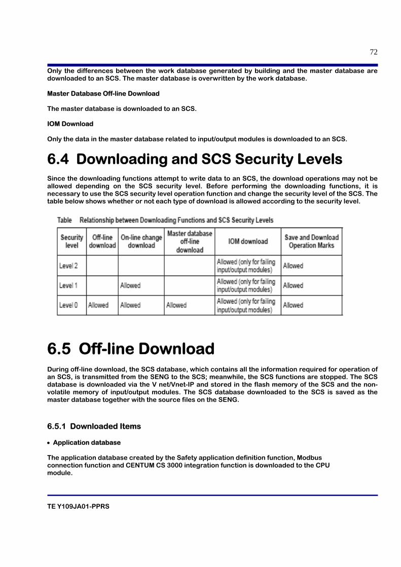
6.4 Downloading and SCS Security Levels Since the downloading functions attempt to write data to an SCS, the download operations may not be allowed depending on the SCS security level. Before performing the downloading functions, it is necessary to use the SCS security level operation function and change the security level of the SCS. The table below shows whether or not each type of download is allowed according to the security level.
6.5 Off-line Download During off-line download, the SCS database, which contains all the information required for operation of an SCS, is transmitted from the SENG to the SCS; meanwhile, the SCS functions are stopped. The SCS database is downloaded via the V net/Vnet-IP and stored in the flash memory of the SCS and the non-volatile memory of input/output modules. The SCS database downloaded to the SCS is saved as the master database together with the source files on the SENG.
6.5.1 Downloaded Items • Application database The application database created by the Safety application definition function, Modbus connection function and CENTUM CS 3000 integration function is downloaded to the CPU module.
TE Y109JA01-PPRS
73
• I/O configuration information The parts of the database created by the I/O definition function related to input/output modules are downloaded to the input/output modules. • The following operations are performed if you execute off-line download. • Functions that run on the SCS stop and all the output modules output the fail-safe value specified in I/O Parameter Builder. • Inter-SCS safety communication is disconnected. • The forcing function is cancelled. • Override from the HIS is cancelled. • SOEs and diagnostic information collected so far in the SCS are deleted (they are saved in the battery backup memory, though). • The password for changing the SCS security level is deleted. 6.5.2 Procedure for offline Download.
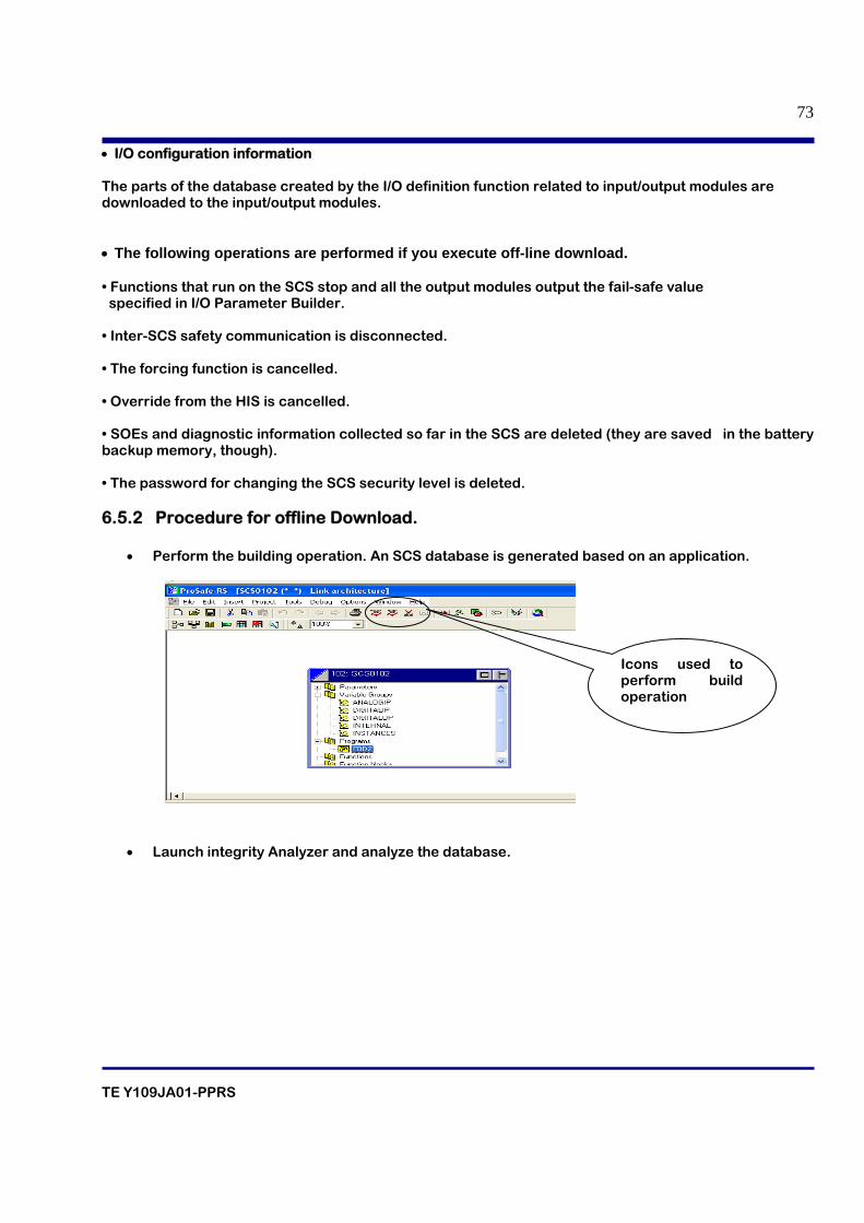
• Perform the building operation. An SCS database is generated based on an application.
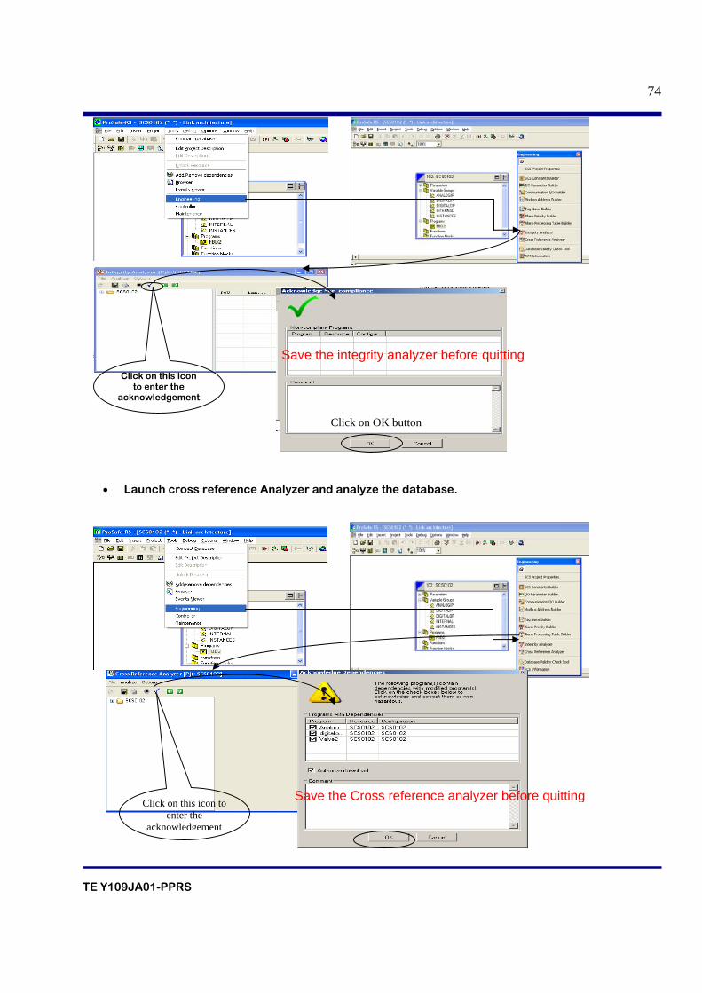
• Launch integrity Analyzer and analyze the database.
Icons used to perform build operation
TE Y109JA01-PPRS
74
• Launch cross reference Analyzer and analyze the database.
Click on this icon to enter the
acknowledgement
Click on OK button
Save the integrity analyzer before quitting
Click on this icon to enter the
acknowledgement
Save the Cross reference analyzer before quitting
TE Y109JA01-PPRS
75
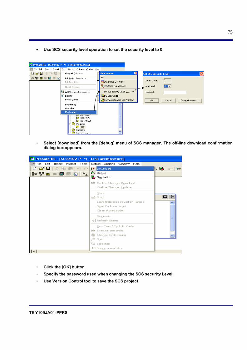
• Use SCS security level operation to set the security level to 0.
• Select [download] from the [debug] menu of SCS manager. The off-line download confirmation dialog box appears.
• Click the [OK] button.
• Specify the password used when changing the SCS security Level.
• Use Version Control tool to save the SCS project.
TE Y109JA01-PPRS
76
6.5.3 Integrity analyzer Integrity Analyzer analyzes application logics, detects “functions that are not allowed to be used” for the functions for safety and displays them in the window by highlighting for visual emphasis. The user can check whether or not functions prohibited from use for safety applications are used or not. Analysis results can be printed as well. If there is a program that intentionally makes use of functions prohibited from use for application, the user can acknowledge their use for each program upon examining the program based on the results of the analysis. If functions prohibited from use for safety applications are used unintentionally, the application logic must be modified. Make changes to the application logic, perform a build operation and then analyze the application logic with Integrity Analyzer again. 6.5.4 Cross reference analyzer Cross Reference Analyzer displays the differences between the previously downloaded application (the application currently running in an SCS) and the application to be downloaded, and the extent to which the download will affect the operation in a window by highlighting them visually, in order to limit the range of re-testing caused by changes in an application logic. The user can check programs that require re-testing, and print the analysis results. Cross Reference Analyzer detects programs that depend on the changed program as programs requiring re-testing. A list of programs requiring re-testing is displayed; they can be acknowledged upon checking the analysis results of each program. If unintended program changes and dependencies are detected, the application logic must be modified. Modify the application logic, perform a build operation and then analyze the application logic with Cross Reference Analyzer again. If no program is found for retesting, retesting will not be performed. However, since the modifications on a certain items may not be discovered for retesting, these modified items need to be tested accordingly.
6.6 Online Change Download On-line change download changes a part of an application without interrupting the SCS functions. In SCS, the data stored in the main memory of the CPU module is updated and changes are stored in the flash memory of the CPU module as well. When performing on-line change download of I/O definitions, changes are also reflected in the non-volatile memory of the input/output modules. Data downloaded to an SCS is also saved in the master database on the SENG. 6.6.1 Procedure for On-line Change Download
• Perform the building operation.
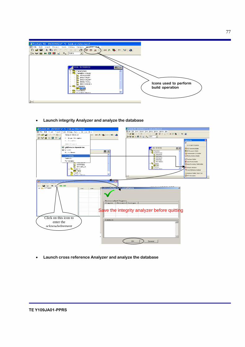
TE Y109JA01-PPRS
77
• Launch integrity Analyzer and analyze the database
• Launch cross reference Analyzer and analyze the database
Icons used to perform build operation
Click on this icon to enter the
acknowledgement
Save the integrity analyzer before quitting
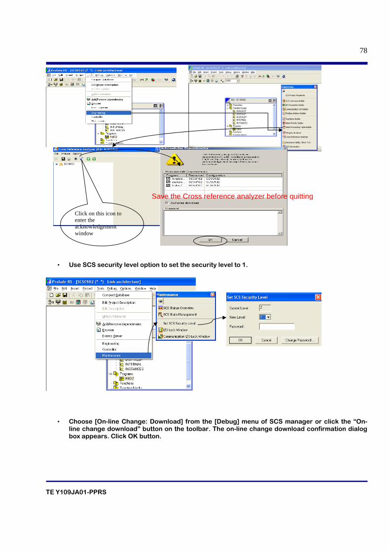
TE Y109JA01-PPRS
78
• Use SCS security level option to set the security level to 1.
• Choose [On-line Change: Download] from the [Debug] menu of SCS manager or click the “On-line change download” button on the toolbar. The on-line change download confirmation dialog box appears. Click OK button.
Click on this icon to enter the acknowledgement window
Save the Cross reference analyzer before quitting
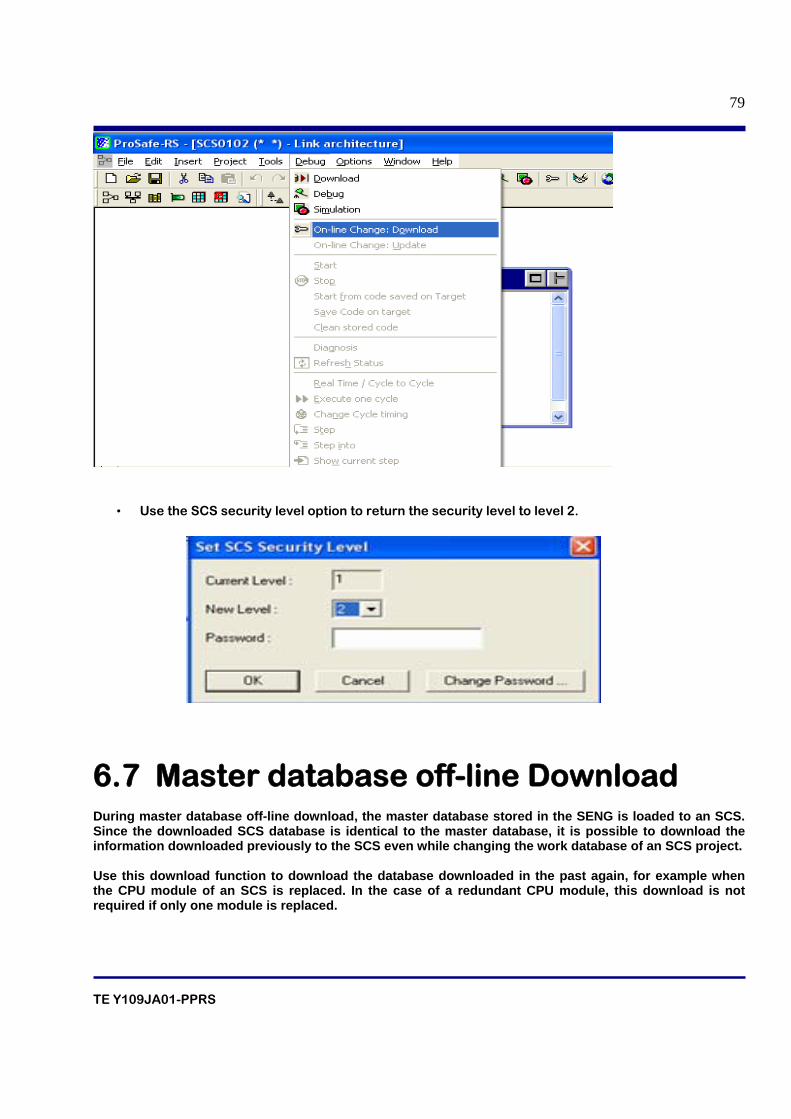
TE Y109JA01-PPRS
79
• Use the SCS security level option to return the security level to level 2.
6.7 Master database off-line Download During master database off-line download, the master database stored in the SENG is loaded to an SCS. Since the downloaded SCS database is identical to the master database, it is possible to download the information downloaded previously to the SCS even while changing the work database of an SCS project. Use this download function to download the database downloaded in the past again, for example when the CPU module of an SCS is replaced. In the case of a redundant CPU module, this download is not required if only one module is replaced.
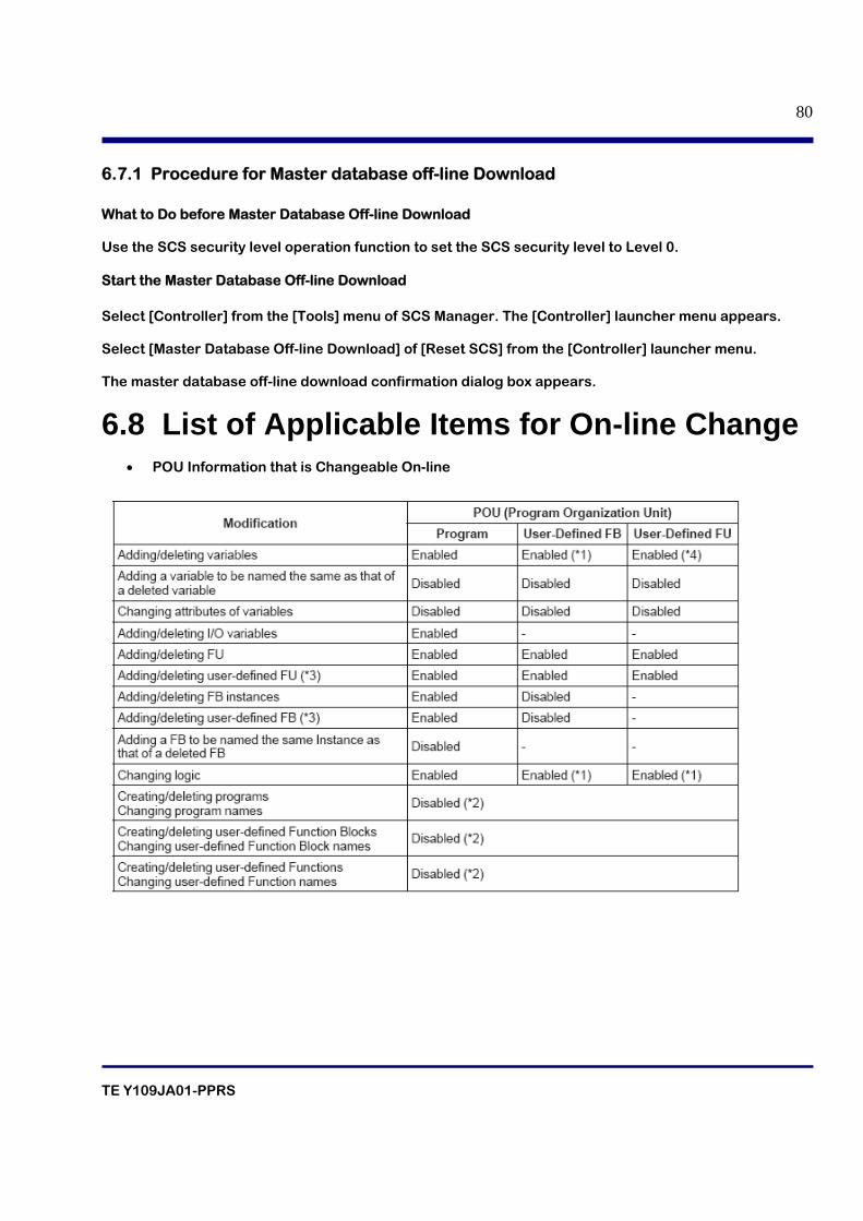
TE Y109JA01-PPRS
80
6.7.1 Procedure for Master database off-line Download What to Do before Master Database Off-line Download Use the SCS security level operation function to set the SCS security level to Level 0. Start the Master Database Off-line Download Select [Controller] from the [Tools] menu of SCS Manager. The [Controller] launcher menu appears. Select [Master Database Off-line Download] of [Reset SCS] from the [Controller] launcher menu. The master database off-line download confirmation dialog box appears.
6.8 List of Applicable Items for On-line Change
• POU Information that is Changeable On-line
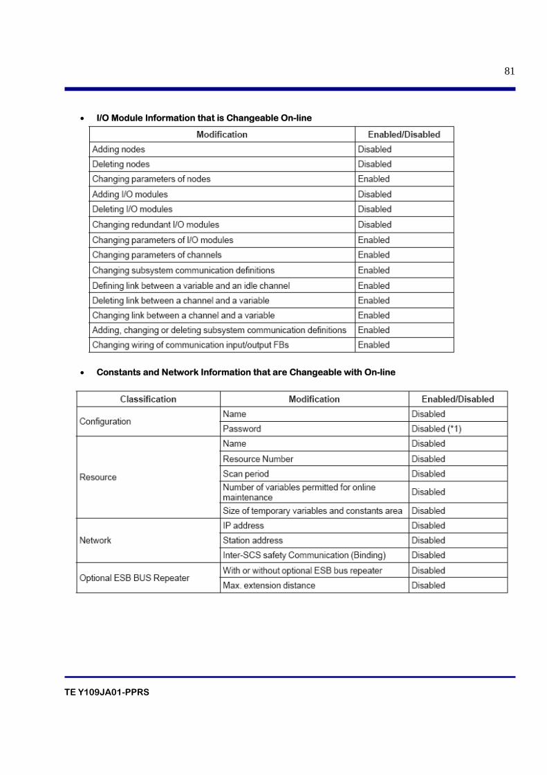
TE Y109JA01-PPRS
81
• I/O Module Information that is Changeable On-line
• Constants and Network Information that are Changeable with On-line
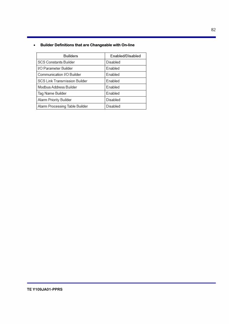
TE Y109JA01-PPRS
82
• Builder Definitions that are Changeable with On-line
TE Y109JA01-PPRS
83
7. IEC61131-3 FBD-LD
TE Y109JA01-PPRS
84
Table of contents
7.1 Introduction
7.2 Function and Function elements
7.2.1 Common elements
7.2.1.1 Identifiers
7.2.1.2 Comments
7.2.1.3 Functions
7.2.2 Variable types
7.2.2.1 Local Variables
7.2.2.2 Global Variables
7.3 Function Block Diagram
7.3.1 Creation of FBD
7.3.2 Creation of logics
7.4 Function blocks
7.4.1 MUXBOOL4
7.4.2 MUXREAL4
7.4.3 SCALER
7.4.4 REPEATTIMER
7.4.5 ANLG1oo2D
7.4.6 BOOLVOTER
7.4.7 ANLG_S
7.4.8 ANLGI
7.4.9 VEL
7.4.10 CTU
7.4.11 CTD
7.5 User Defined Function blocks
TE Y109JA01-PPRS
85
7.1 Introduction IEC61131-3 deals with all aspects of PLC application to Industrial process measurement and control.IEC61131 standard defines the following programming methods
• Function block diagram
• Ladder diagrams
• Instruction list
• Structured text
• Sequence function charts
The Prosafe-RS supports Function block diagrams, ladder diagrams and Structured text. The standard was developed to standardize the programming of PLCs available in the market. This has several advantages:
• A common language means the user need not learn different languages for different PLCs. • Portability of program across different PLCs.
• Allows program to be broken in to functional elements called program organization unit. • Strong data typing
• Self check to detect when wrong data type is assigned to the variable.
• Can describe the complex Sequential behavior.
7.2 Function and Function elements 7.2.1 Common elements
Common elements include Identifiers, Comments and Functions.
7.2.1.1 Identifiers
Identifiers are used for naming different elements such as,
• Variables
• Function blocks
• Programs
The identifiers can be string of letters, digits and underlines provided that:
• The first character is not a digit
• There are no two or more underline characters to getjer
• There are no embedded spaces
7.2.1.2 Comments
Comments of various lengths can be inserted in FBDs and LD.Comments of various length can be inserted in FBD and LD.The comment can be of single line or multi line.
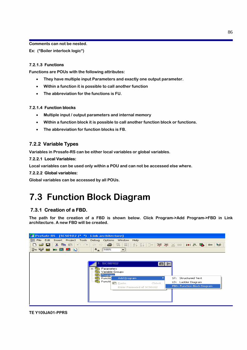
TE Y109JA01-PPRS
86
Comments can not be nested.
Ex: (*Boiler interlock logic*)
7.2.1.3 Functions
Functions are POUs with the following attributes:
• They have multiple input Parameters and exactly one output parameter.
• Within a function it is possible to call another function
• The abbreviation for the functions is FU.
7.2.1.4 Function blocks
• Multiple input / output parameters and internal memory
• Within a function block it is possible to call another function block or functions.
• The abbreviation for function blocks is FB.
7.2.2 Variable Types
Variables in Prosafe-RS can be either local variables or global variables.
7.2.2.1 Local Variables:
Local variables can be used only within a POU and can not be accessed else where.
7.2.2.2 Global variables:
Global variables can be accessed by all POUs.
7.3 Function Block Diagram 7.3.1 Creation of a FBD.
The path for the creation of a FBD is shown below. Click Program->Add Program->FBD in Link architecture. A new FBD will be created.
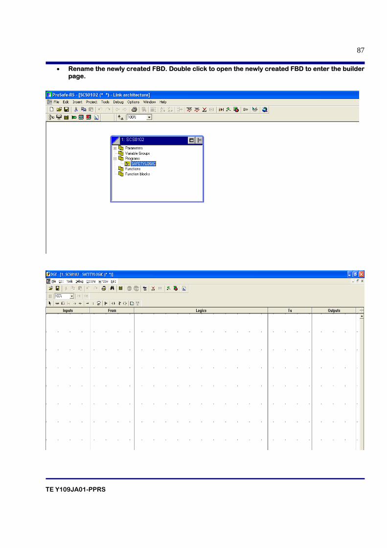
TE Y109JA01-PPRS
87
• Rename the newly created FBD. Double click to open the newly created FBD to enter the builder page.
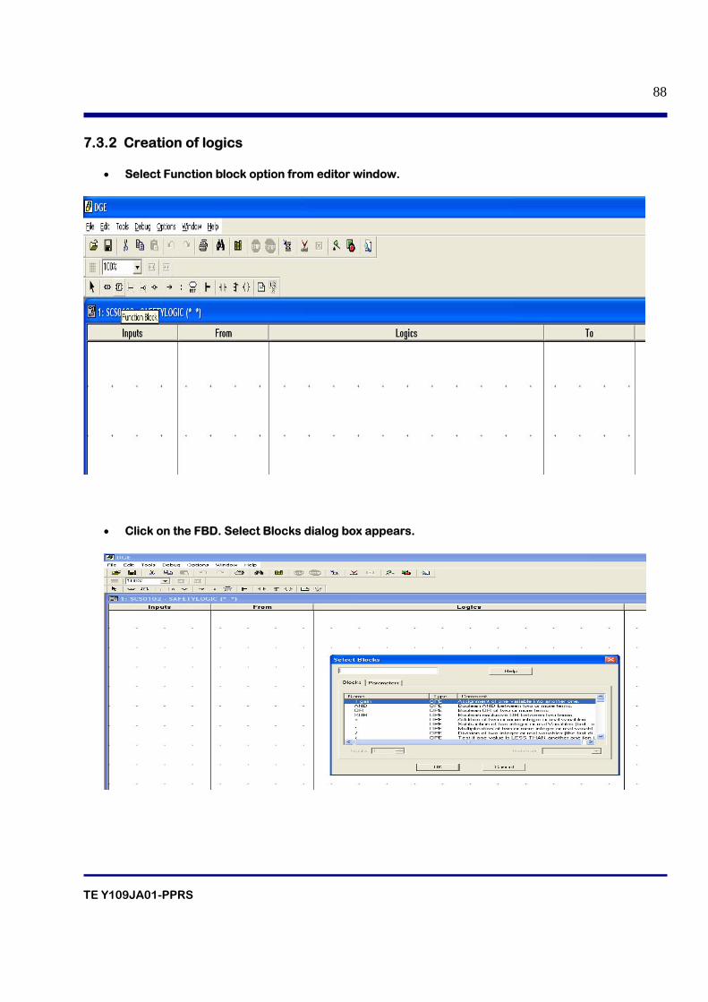
TE Y109JA01-PPRS
88
7.3.2 Creation of logics
• Select Function block option from editor window.
• Click on the FBD. Select Blocks dialog box appears.
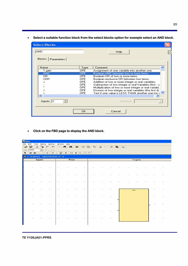
TE Y109JA01-PPRS
89
• Select a suitable function block from the select blocks option for example select an AND block.
• Click on the FBD page to display the AND block.
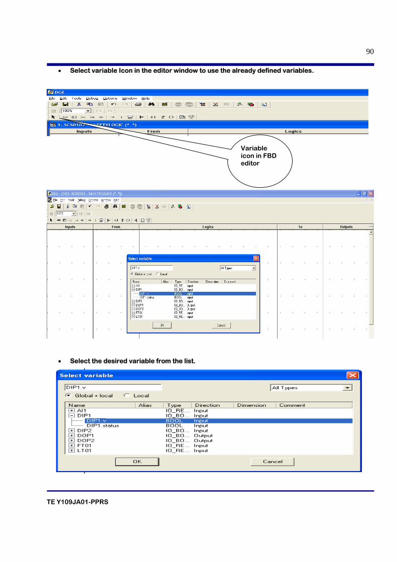
TE Y109JA01-PPRS
90
• Select variable Icon in the editor window to use the already defined variables.
• Select the desired variable from the list.
Variable icon in FBD editor
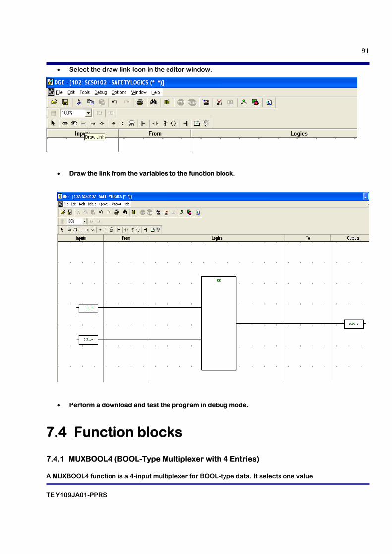
TE Y109JA01-PPRS
91
• Select the draw link Icon in the editor window.
• Draw the link from the variables to the function block.
• Perform a download and test the program in debug mode.
7.4 Function blocks 7.4.1 MUXBOOL4 (BOOL-Type Multiplexer with 4 Entries) A MUXBOOL4 function is a 4-input multiplexer for BOOL-type data. It selects one value
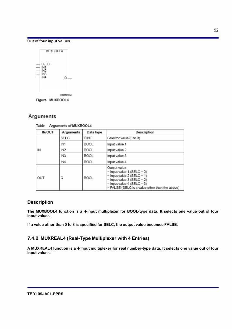
TE Y109JA01-PPRS
92
Out of four input values.
Description The MUXBOOL4 function is a 4-input multiplexer for BOOL-type data. It selects one value out of four input values. If a value other than 0 to 3 is specified for SELC, the output value becomes FALSE. 7.4.2 MUXREAL4 (Real-Type Multiplexer with 4 Entries) A MUXREAL4 function is a 4-input multiplexer for real number-type data. It selects one value out of four input values.
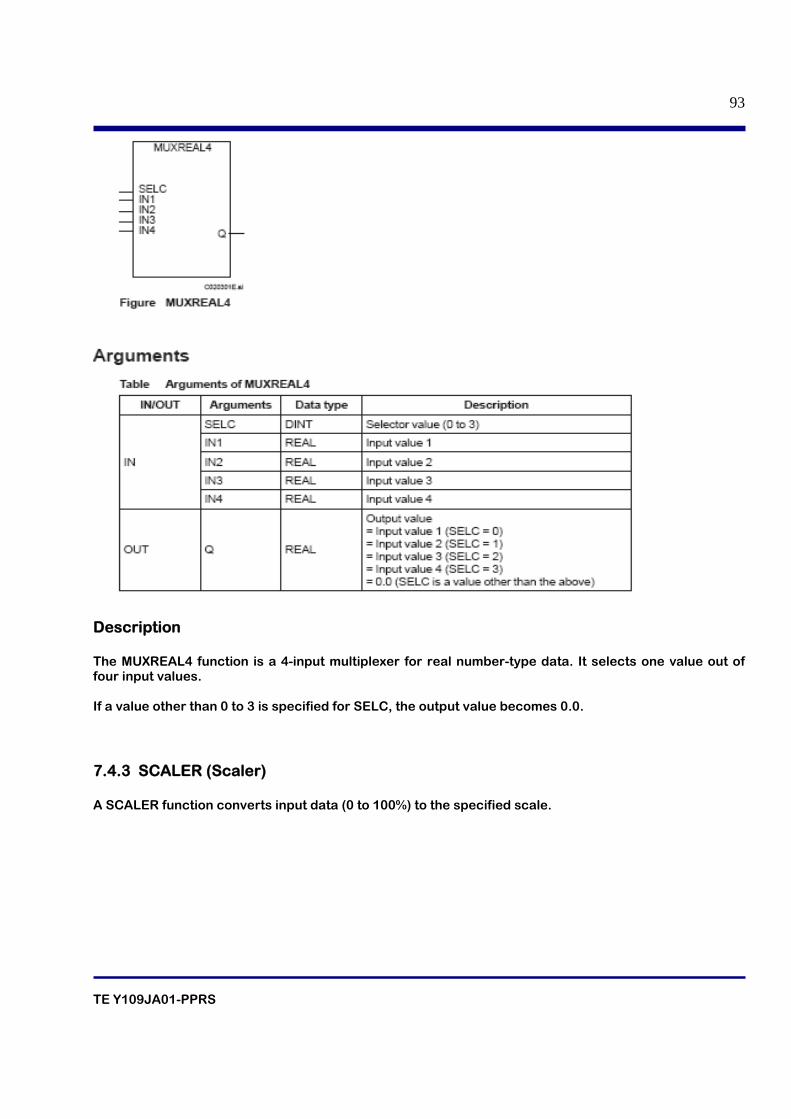
TE Y109JA01-PPRS
93
Description The MUXREAL4 function is a 4-input multiplexer for real number-type data. It selects one value out of four input values. If a value other than 0 to 3 is specified for SELC, the output value becomes 0.0. 7.4.3 SCALER (Scaler) A SCALER function converts input data (0 to 100%) to the specified scale.
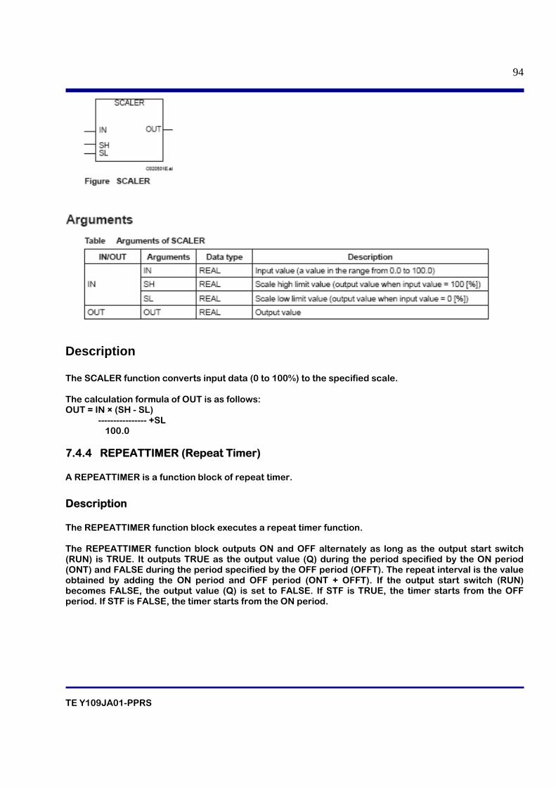
TE Y109JA01-PPRS
94
Description The SCALER function converts input data (0 to 100%) to the specified scale. The calculation formula of OUT is as follows: OUT = IN × (SH - SL) ---------------- +SL
100.0
7.4.4 REPEATTIMER (Repeat Timer) A REPEATTIMER is a function block of repeat timer.
Description The REPEATTIMER function block executes a repeat timer function. The REPEATTIMER function block outputs ON and OFF alternately as long as the output start switch (RUN) is TRUE. It outputs TRUE as the output value (Q) during the period specified by the ON period (ONT) and FALSE during the period specified by the OFF period (OFFT). The repeat interval is the value obtained by adding the ON period and OFF period (ONT + OFFT). If the output start switch (RUN) becomes FALSE, the output value (Q) is set to FALSE. If STF is TRUE, the timer starts from the OFF period. If STF is FALSE, the timer starts from the ON period.
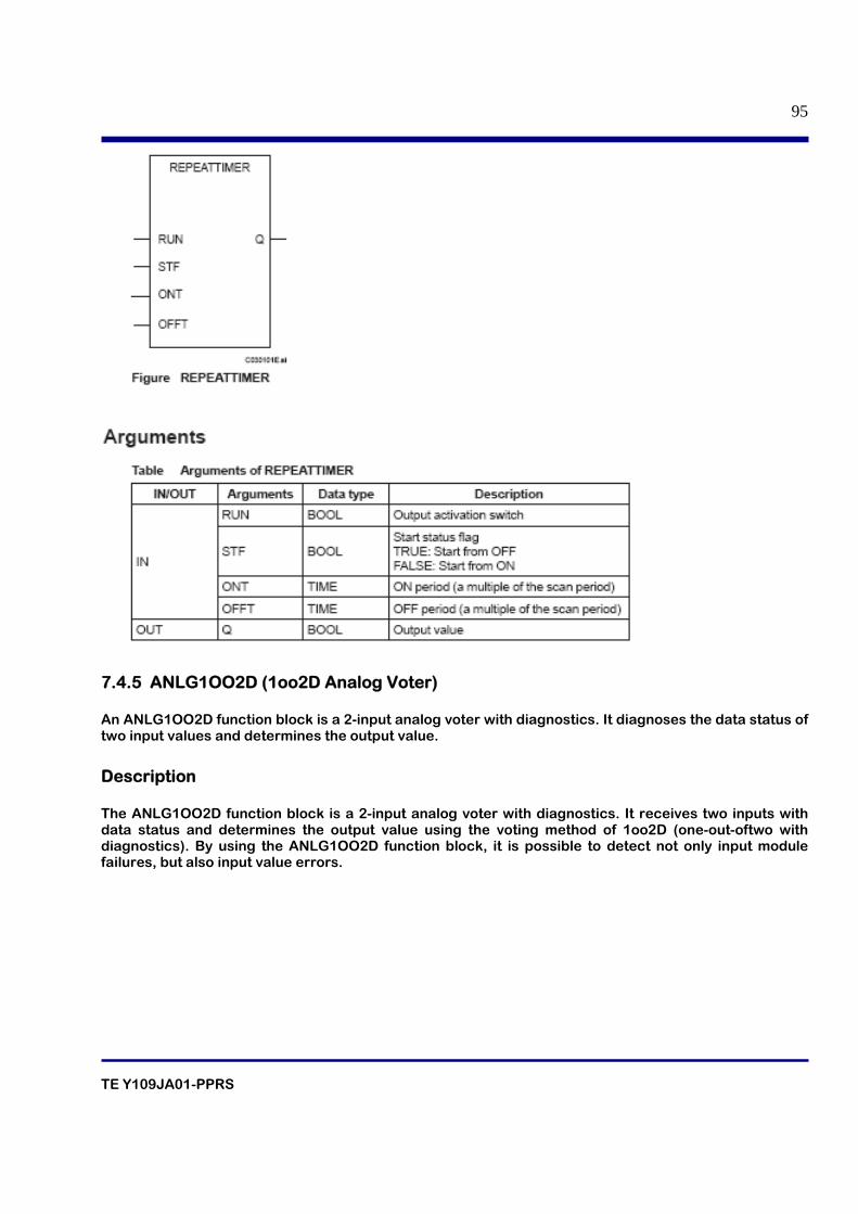
TE Y109JA01-PPRS
95
7.4.5 ANLG1OO2D (1oo2D Analog Voter) An ANLG1OO2D function block is a 2-input analog voter with diagnostics. It diagnoses the data status of two input values and determines the output value.
Description The ANLG1OO2D function block is a 2-input analog voter with diagnostics. It receives two inputs with data status and determines the output value using the voting method of 1oo2D (one-out-oftwo with diagnostics). By using the ANLG1OO2D function block, it is possible to detect not only input module failures, but also input value errors.
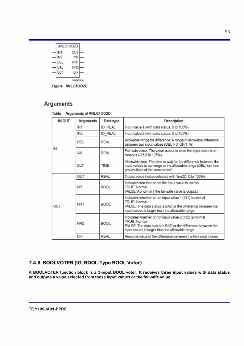
TE Y109JA01-PPRS
96
7.4.6 BOOLVOTER (IO_BOOL-Type BOOL Voter) A BOOLVOTER function block is a 3-input BOOL voter. It receives three input values with data status and outputs a value selected from these input values or the fail-safe value
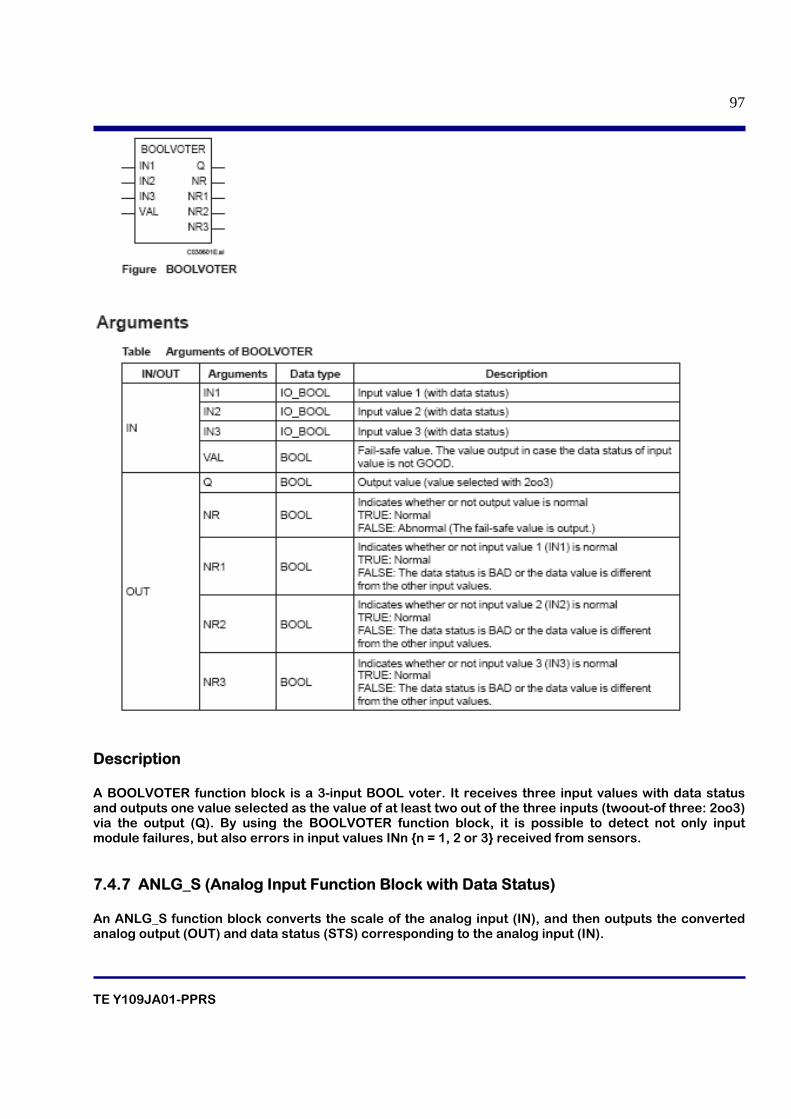
TE Y109JA01-PPRS
97
Description A BOOLVOTER function block is a 3-input BOOL voter. It receives three input values with data status and outputs one value selected as the value of at least two out of the three inputs (twoout-of three: 2oo3) via the output (Q). By using the BOOLVOTER function block, it is possible to detect not only input module failures, but also errors in input values INn {n = 1, 2 or 3} received from sensors. 7.4.7 ANLG_S (Analog Input Function Block with Data Status) An ANLG_S function block converts the scale of the analog input (IN), and then outputs the converted analog output (OUT) and data status (STS) corresponding to the analog input (IN).
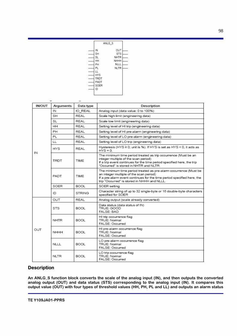
TE Y109JA01-PPRS
98
Description An ANLG_S function block converts the scale of the analog input (IN), and then outputs the converted analog output (OUT) and data status (STS) corresponding to the analog input (IN). It compares this output value (OUT) with four types of threshold values (HH, PH, PL and LL) and outputs an alarm status
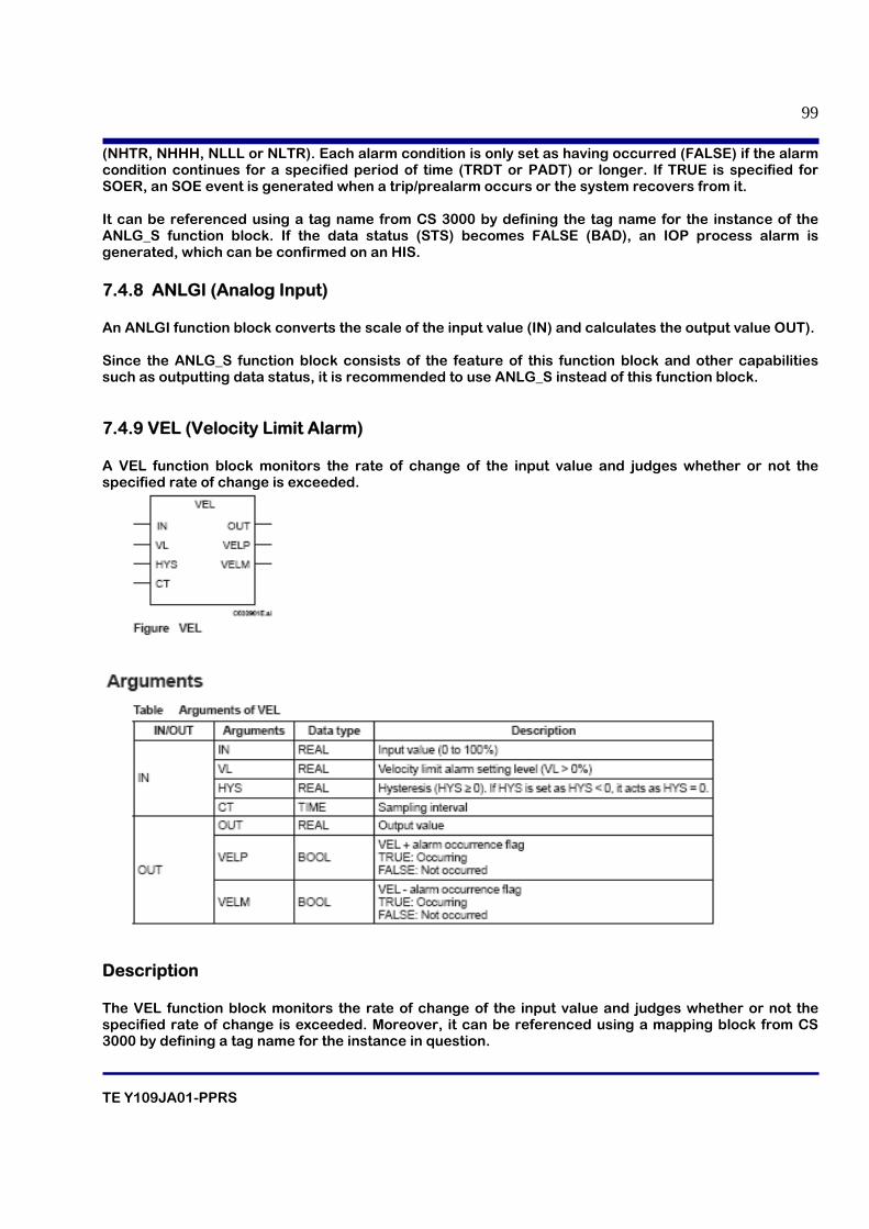
TE Y109JA01-PPRS
99
(NHTR, NHHH, NLLL or NLTR). Each alarm condition is only set as having occurred (FALSE) if the alarm condition continues for a specified period of time (TRDT or PADT) or longer. If TRUE is specified for SOER, an SOE event is generated when a trip/prealarm occurs or the system recovers from it. It can be referenced using a tag name from CS 3000 by defining the tag name for the instance of the ANLG_S function block. If the data status (STS) becomes FALSE (BAD), an IOP process alarm is generated, which can be confirmed on an HIS. 7.4.8 ANLGI (Analog Input) An ANLGI function block converts the scale of the input value (IN) and calculates the output value OUT). Since the ANLG_S function block consists of the feature of this function block and other capabilities such as outputting data status, it is recommended to use ANLG_S instead of this function block. 7.4.9 VEL (Velocity Limit Alarm) A VEL function block monitors the rate of change of the input value and judges whether or not the specified rate of change is exceeded.
Description The VEL function block monitors the rate of change of the input value and judges whether or not the specified rate of change is exceeded. Moreover, it can be referenced using a mapping block from CS 3000 by defining a tag name for the instance in question.
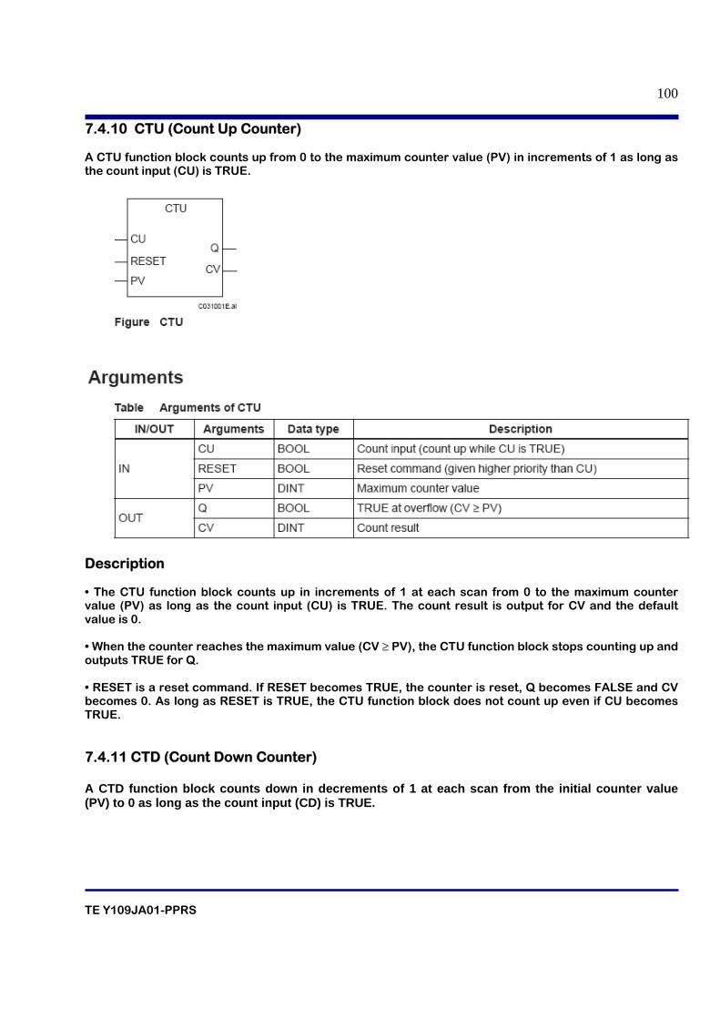
TE Y109JA01-PPRS
100
7.4.10 CTU (Count Up Counter) A CTU function block counts up from 0 to the maximum counter value (PV) in increments of 1 as long as the count input (CU) is TRUE.
Description • The CTU function block counts up in increments of 1 at each scan from 0 to the maximum counter value (PV) as long as the count input (CU) is TRUE. The count result is output for CV and the default value is 0. • When the counter reaches the maximum value (CV ≥ PV), the CTU function block stops counting up and outputs TRUE for Q. • RESET is a reset command. If RESET becomes TRUE, the counter is reset, Q becomes FALSE and CV becomes 0. As long as RESET is TRUE, the CTU function block does not count up even if CU becomes TRUE. 7.4.11 CTD (Count Down Counter) A CTD function block counts down in decrements of 1 at each scan from the initial counter value (PV) to 0 as long as the count input (CD) is TRUE.
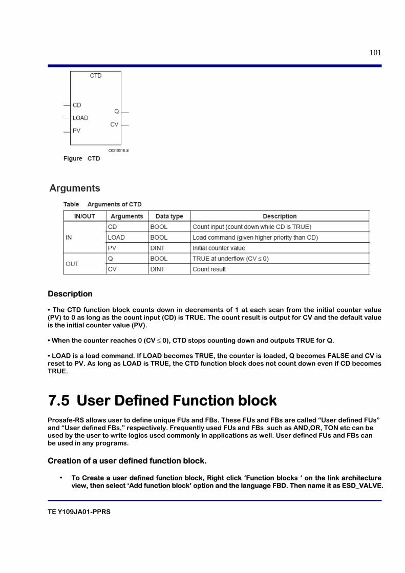
TE Y109JA01-PPRS
101
Description • The CTD function block counts down in decrements of 1 at each scan from the initial counter value (PV) to 0 as long as the count input (CD) is TRUE. The count result is output for CV and the default value is the initial counter value (PV). • When the counter reaches 0 (CV ≤ 0), CTD stops counting down and outputs TRUE for Q. • LOAD is a load command. If LOAD becomes TRUE, the counter is loaded, Q becomes FALSE and CV is reset to PV. As long as LOAD is TRUE, the CTD function block does not count down even if CD becomes TRUE.
7.5 User Defined Function block Prosafe-RS allows user to define unique FUs and FBs. These FUs and FBs are called “User defined FUs” and “User defined FBs,” respectively. Frequently used FUs and FBs such as AND,OR, TON etc can be used by the user to write logics used commonly in applications as well. User defined FUs and FBs can be used in any programs. Creation of a user defined function block.
• To Create a user defined function block, Right click ‘Function blocks ‘ on the link architecture view, then select ‘Add function block’ option and the language FBD. Then name it as ESD_VALVE.
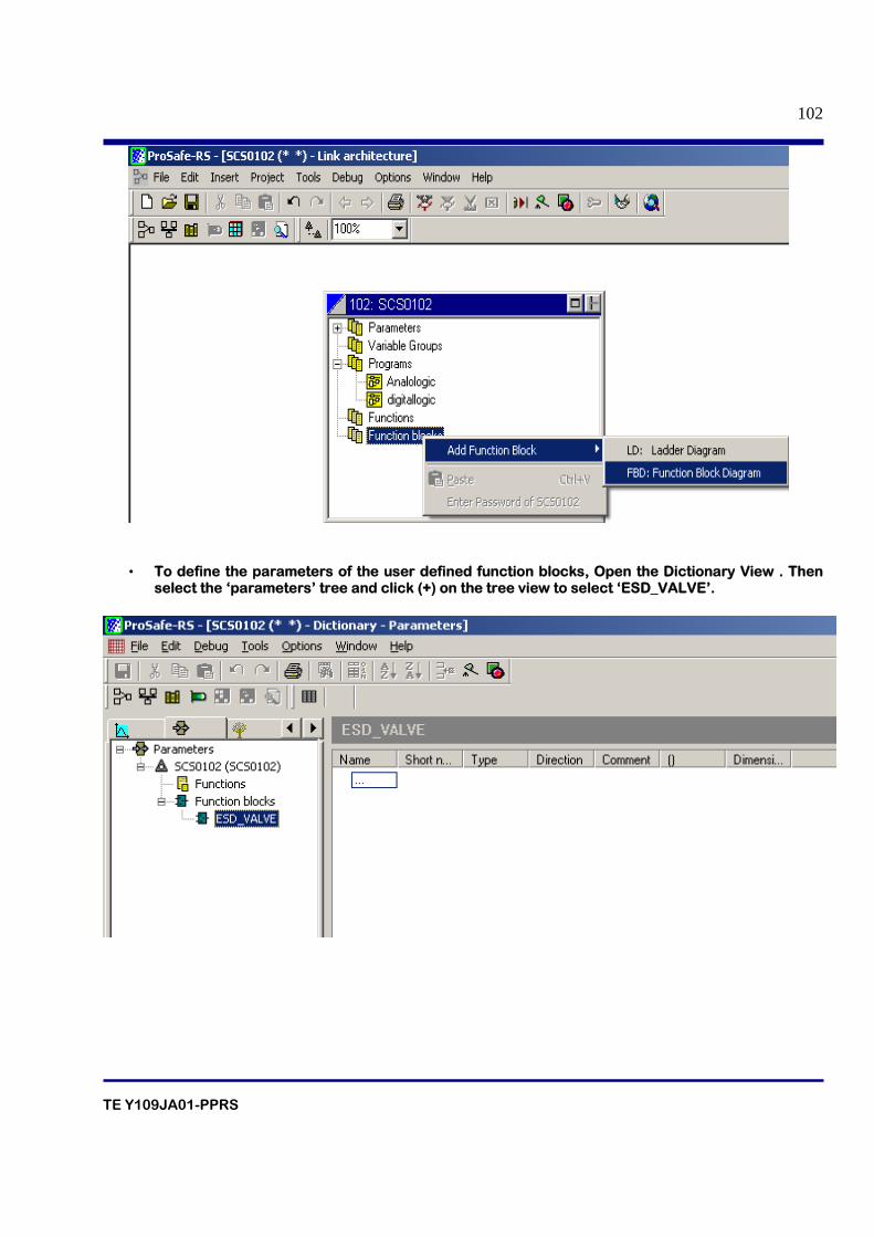
TE Y109JA01-PPRS
102
• To define the parameters of the user defined function blocks, Open the Dictionary View . Then select the ‘parameters’ tree and click (+) on the tree view to select ‘ESD_VALVE’.
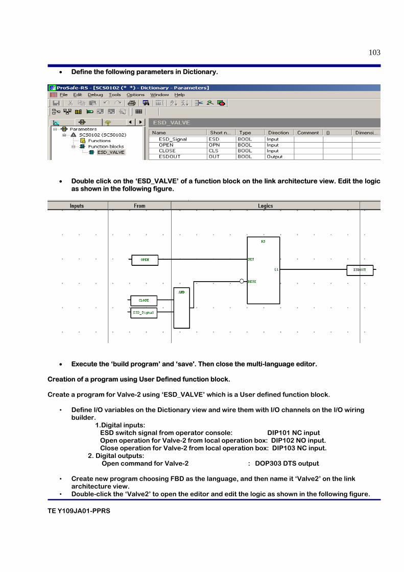
TE Y109JA01-PPRS
103
• Define the following parameters in Dictionary.
• Double click on the ‘ESD_VALVE’ of a function block on the link architecture view. Edit the logic
as shown in the following figure.
• Execute the ‘build program’ and ‘save'. Then close the multi-language editor. Creation of a program using User Defined function block. Create a program for Valve-2 using ‘ESD_VALVE’ which is a User defined function block.
• Define I/O variables on the Dictionary view and wire them with I/O channels on the I/O wiring builder.
1.Digital inputs: ESD switch signal from operator console: DIP101 NC input Open operation for Valve-2 from local operation box: DIP102 NO input. Close operation for Valve-2 from local operation box: DIP103 NC input. 2. Digital outputs: Open command for Valve-2 : DOP303 DTS output
• Create new program choosing FBD as the language, and then name it ‘Valve2’ on the link architecture view.
• Double-click the ‘Valve2’ to open the editor and edit the logic as shown in the following figure.
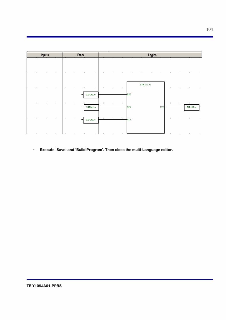
TE Y109JA01-PPRS
104
• Execute ‘Save’ and ‘Build Program'. Then close the multi-Language editor.
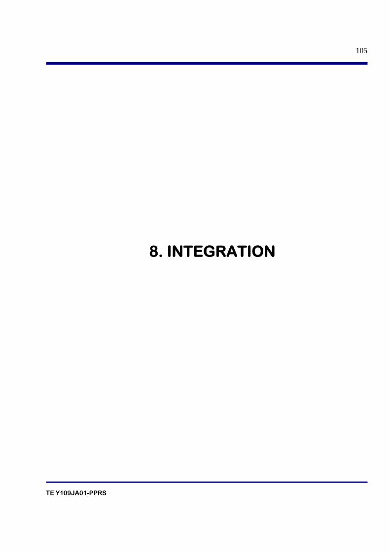
TE Y109JA01-PPRS
105
8. INTEGRATION
TE Y109JA01-PPRS
106
Table of contents 8.1 Introduction
8.2 Overview of Operation and Monitoring from HIS. 8.3 Engineering on the SENG Side 8.4 Engineering on the CS 3000 Side 8.5 Integration of ANLG_S with CS3000
8.6 Function blocks for integration with CS3000
8.6.1 Override Function Blocks
8.6.2 PASSWD (Password)
8.6.3 ANN
8.7 Inter SCS communication 8.7.1 Function Blocks details for Inter-SCS Communication
TE Y109JA01-PPRS
107
8.1 Overview of CS 3000 Integration The CS 3000 Integration Function of the ProSafe-RS provides a communication interface for accessing SCS of ProSafe-RS from HIS and FCS of CENTUM CS 3000 system (hereinafter referred to as “CS 3000”). By this function, you can operate and monitor SCS from HIS using the same interfaces (windows) for operating and monitoring FCS. You can also access SCS data from FCS using the same interface (tag names) used by an FCS to access other FCS.
8.2 Overview of Operation and Monitoring from HIS. In the CS 3000 integration, the following operations are possible from HIS to SCS: • To use tag names to operate and monitor SCS data via the same interface used to monitor FCS data. • To monitor the status of process alarms and annunciators generated on SCSs in HIS’s Process Alarm window. • To monitor the system alarms generated on SCS in HIS’s System Alarm window. • To display the status of each SCS in HIS’s SCS Status Display window. • To override the application logic variables. • To set output of the application logics.
8.3 Engineering on the SENG Side This section describes the engineering tasks performed on the SENG side, among the tasks required to connect an SCS project and a CS 3000 project.
Setting of SCS Project Property An SCS project and a CS 3000 project can be connected using SCS Project Properties in SCS manager. In SCS Project Properties, specify the folder of the CS 3000 project you want to connect to the SCS project. The information for CS 3000 integration that has been set in the SCS project can be copied to the CS 3000 project folder. The connection of an SCS project and a CS 3000 project is set only in one direction: from the SCS project to the CS 3000 project.
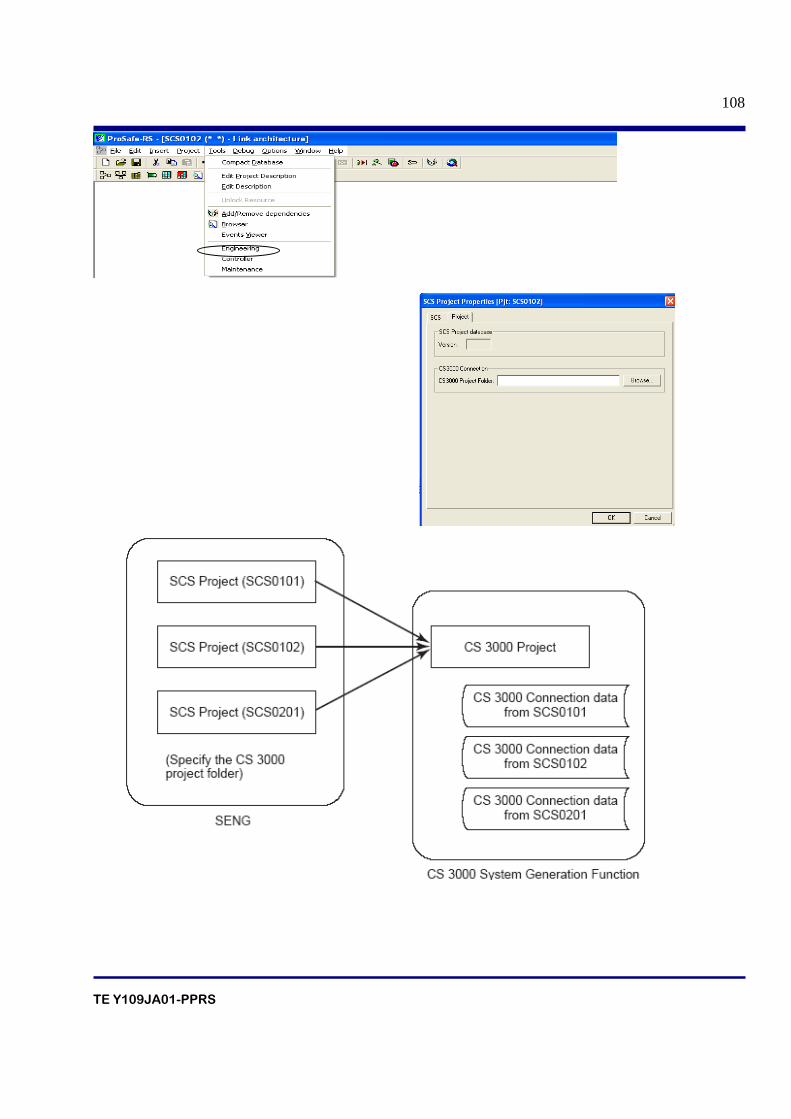
TE Y109JA01-PPRS
108
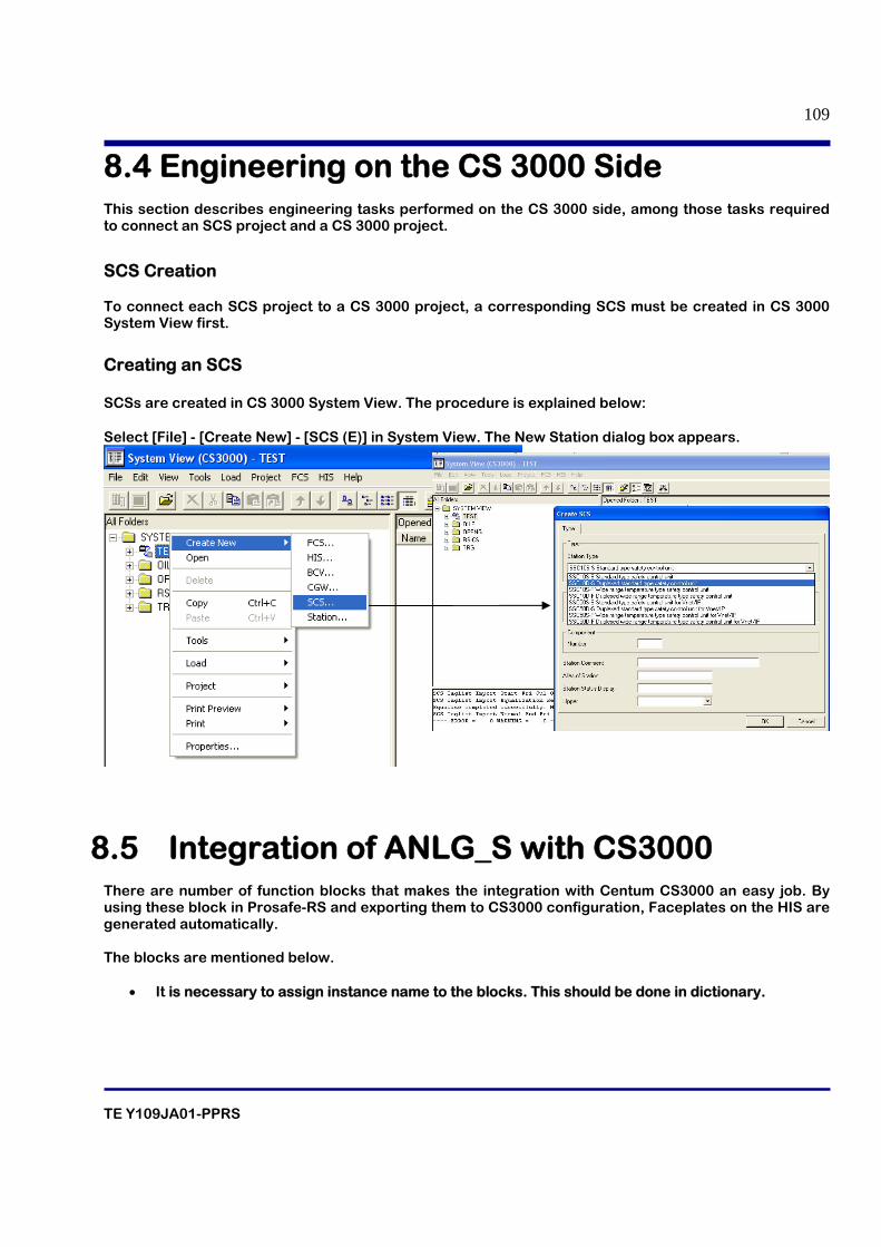
TE Y109JA01-PPRS
109
8.4 Engineering on the CS 3000 Side This section describes engineering tasks performed on the CS 3000 side, among those tasks required to connect an SCS project and a CS 3000 project.
SCS Creation To connect each SCS project to a CS 3000 project, a corresponding SCS must be created in CS 3000 System View first.
Creating an SCS SCSs are created in CS 3000 System View. The procedure is explained below: Select [File] - [Create New] - [SCS (E)] in System View. The New Station dialog box appears.
8.5 Integration of ANLG_S with CS3000 There are number of function blocks that makes the integration with Centum CS3000 an easy job. By using these block in Prosafe-RS and exporting them to CS3000 configuration, Faceplates on the HIS are generated automatically. The blocks are mentioned below.
• It is necessary to assign instance name to the blocks. This should be done in dictionary.
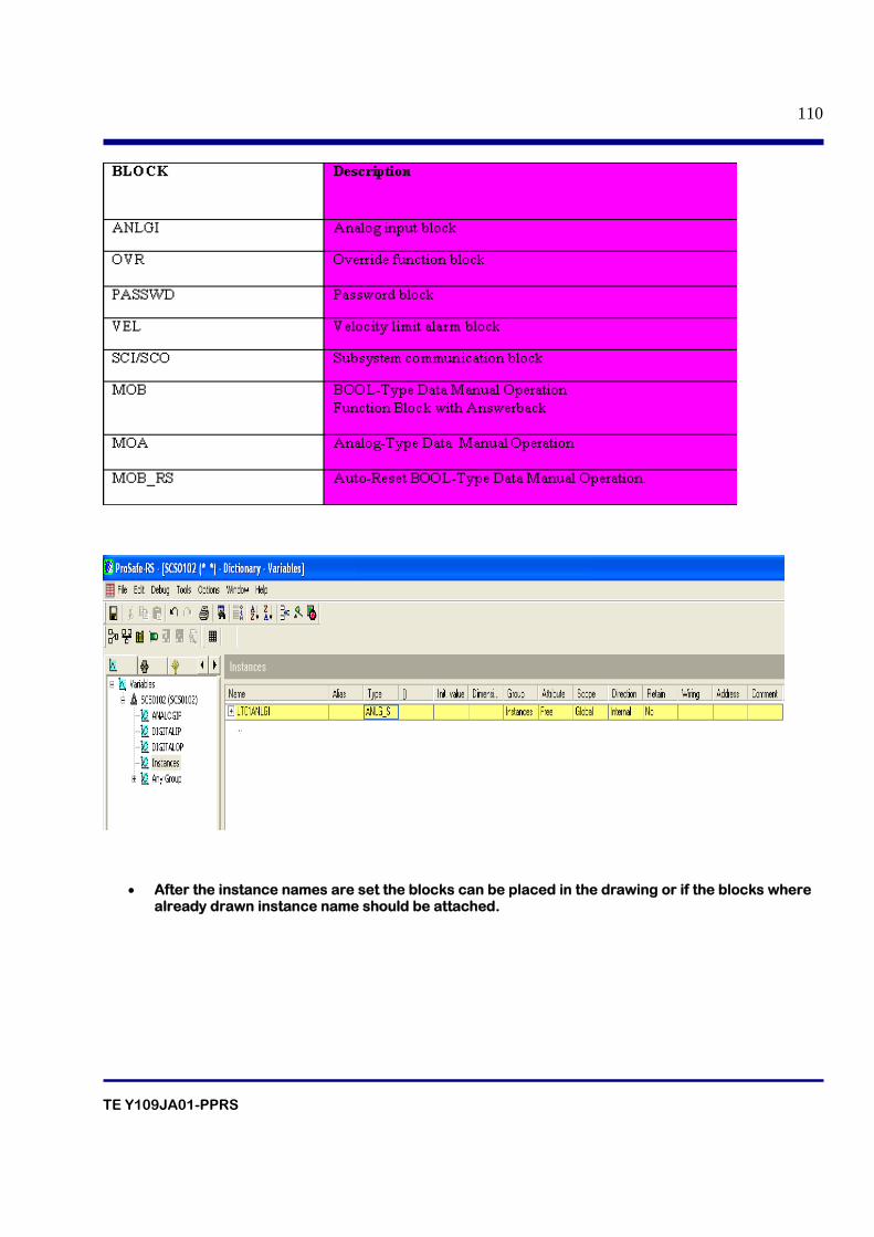
TE Y109JA01-PPRS
110
• After the instance names are set the blocks can be placed in the drawing or if the blocks where already drawn instance name should be attached.
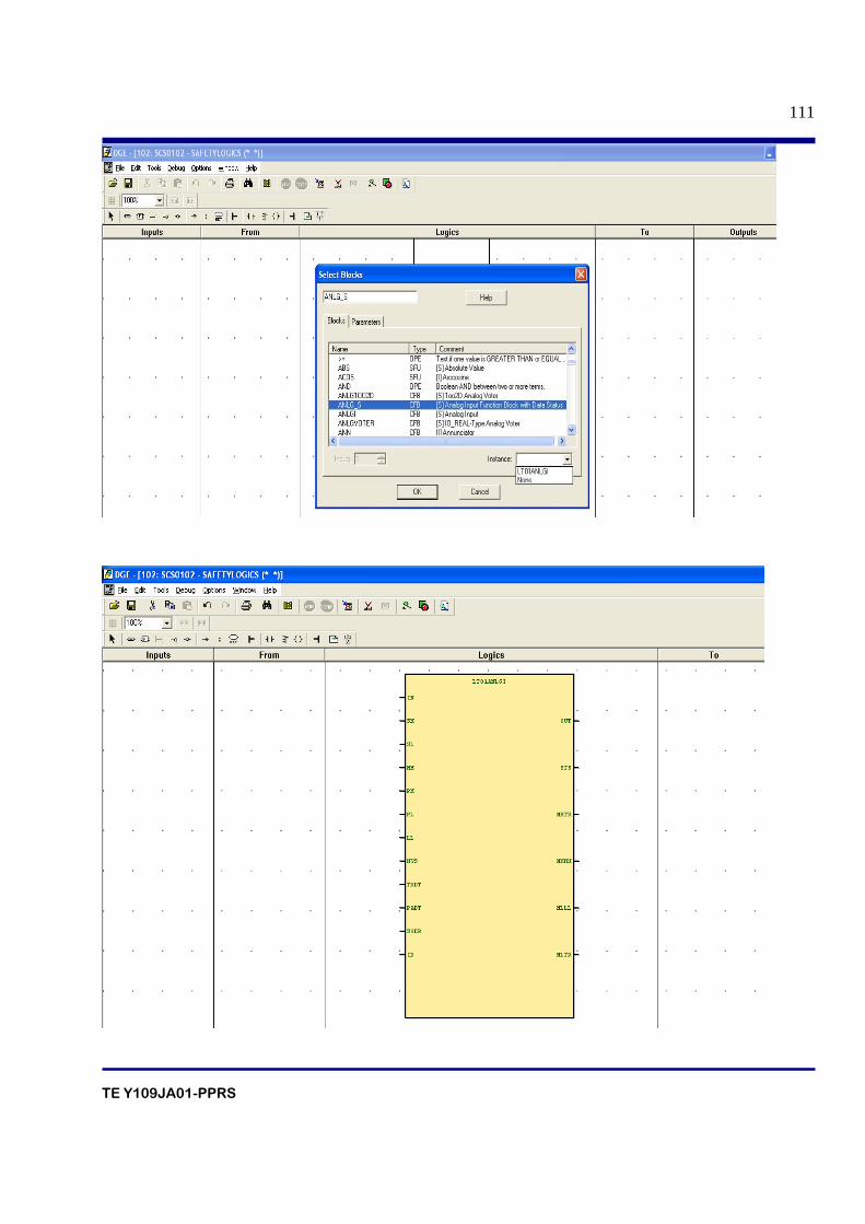
TE Y109JA01-PPRS
111
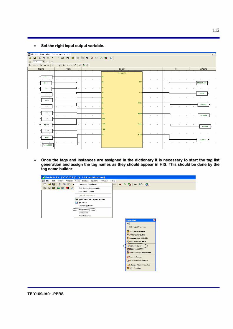
TE Y109JA01-PPRS
112
• Set the right input output variable.
• Once the tags and instances are assigned in the dictionary it is necessary to start the tag list generation and assign the tag names as they should appear in HIS. This should be done by the tag name builder.
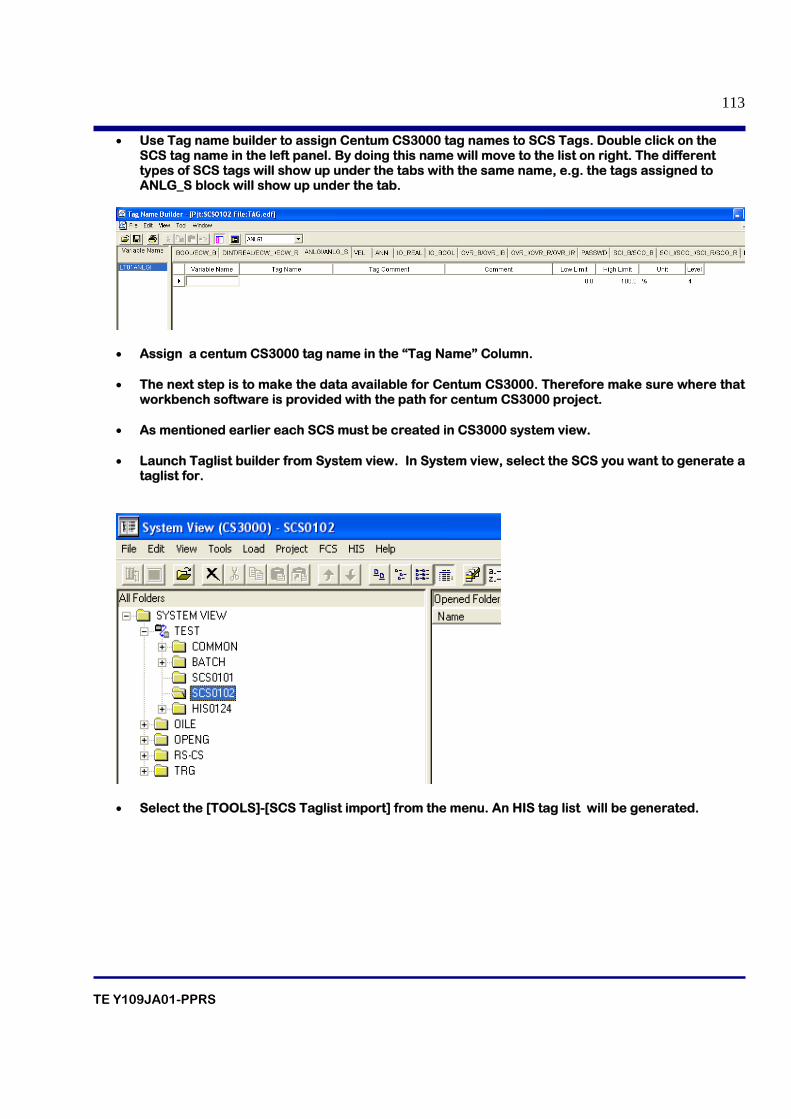
TE Y109JA01-PPRS
113
• Use Tag name builder to assign Centum CS3000 tag names to SCS Tags. Double click on the SCS tag name in the left panel. By doing this name will move to the list on right. The different types of SCS tags will show up under the tabs with the same name, e.g. the tags assigned to ANLG_S block will show up under the tab.
• Assign a centum CS3000 tag name in the “Tag Name” Column. • The next step is to make the data available for Centum CS3000. Therefore make sure where that
workbench software is provided with the path for centum CS3000 project.
• As mentioned earlier each SCS must be created in CS3000 system view.
• Launch Taglist builder from System view. In System view, select the SCS you want to generate a taglist for.
• Select the [TOOLS]-[SCS Taglist import] from the menu. An HIS tag list will be generated.
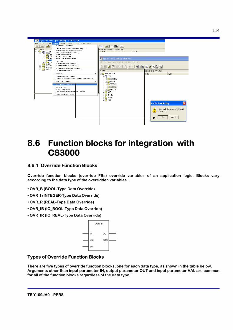
TE Y109JA01-PPRS
114
8.6 Function blocks for integration with CS3000
8.6.1 Override Function Blocks Override function blocks (override FBs) override variables of an application logic. Blocks vary according to the data type of the overridden variables. • OVR_B (BOOL-Type Data Override)
• OVR_I (INTEGER-Type Data Override)
• OVR_R (REAL-Type Data Override)
• OVR_IB (IO_BOOL-Type Data Override)
• OVR_IR (IO_REAL-Type Data Override)
Types of Override Function Blocks There are five types of override function blocks, one for each data type, as shown in the table below. Arguments other than input parameter IN, output parameter OUT and input parameter VAL are common for all of the function blocks regardless of the data type.
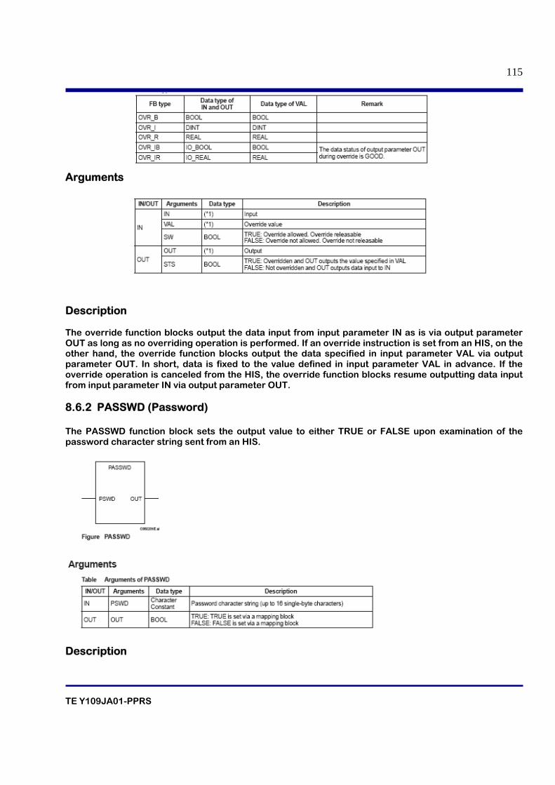
TE Y109JA01-PPRS
115
Arguments
Description The override function blocks output the data input from input parameter IN as is via output parameter OUT as long as no overriding operation is performed. If an override instruction is set from an HIS, on the other hand, the override function blocks output the data specified in input parameter VAL via output parameter OUT. In short, data is fixed to the value defined in input parameter VAL in advance. If the override operation is canceled from the HIS, the override function blocks resume outputting data input from input parameter IN via output parameter OUT. 8.6.2 PASSWD (Password) The PASSWD function block sets the output value to either TRUE or FALSE upon examination of the password character string sent from an HIS.
Description
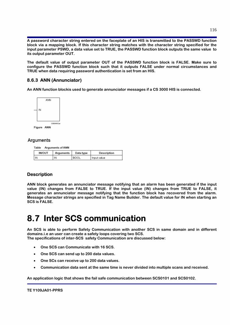
TE Y109JA01-PPRS
116
A password character string entered on the faceplate of an HIS is transmitted to the PASSWD function block via a mapping block. If this character string matches with the character string specified for the input parameter PSWD, a data value set to TRUE, the PASSWD function block outputs the same value to its output parameter OUT. The default value of output parameter OUT of the PASSWD function block is FALSE. Make sure to configure the PASSWD function block such that it outputs FALSE under normal circumstances and TRUE when data requiring password authentication is set from an HIS.
8.6.3 ANN (Annunciator) An ANN function blockis used to generate annunciator messages if a CS 3000 HIS is connected.
Description ANN block generates an annunciator message notifying that an alarm has been generated if the input value (IN) changes from FALSE to TRUE. If the input value (IN) changes from TRUE to FALSE, it generates an annunciator message notifying that the function block has recovered from the alarm. Message character strings are specified in Tag Name Builder. The default value for IN when starting an SCS is FALSE.
8.7 Inter SCS communication An SCS is able to perform Safety Communication with another SCS in same domain and in different domains.i.e an user can create a safety loops covering two SCS. The specifications of inter-SCS safety Communication are discussed below:
• One SCS can Communicate with 16 SCS.
• One SCS can send up to 200 data values.
• One SCs can receive up to 200 data values.
• Communication data sent at the same time is never divided into multiple scans and received.
An application logic that shows the fail safe communication between SCS0101 and SCS0102.
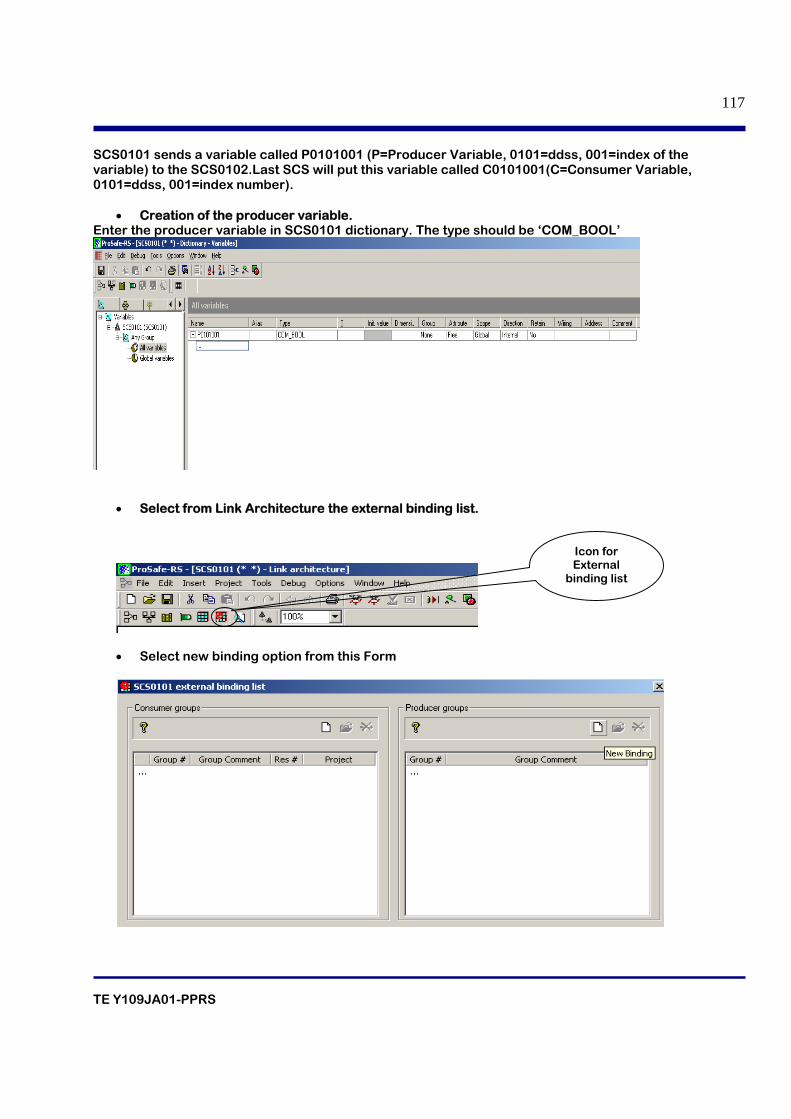
TE Y109JA01-PPRS
117
SCS0101 sends a variable called P0101001 (P=Producer Variable, 0101=ddss, 001=index of the variable) to the SCS0102.Last SCS will put this variable called C0101001(C=Consumer Variable, 0101=ddss, 001=index number).
• Creation of the producer variable. Enter the producer variable in SCS0101 dictionary. The type should be ‘COM_BOOL’
• Select from Link Architecture the external binding list.
• Select new binding option from this Form
Icon for External
binding list
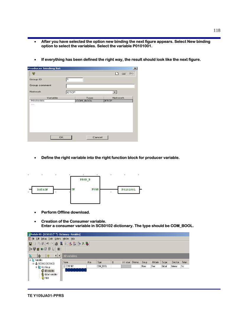
TE Y109JA01-PPRS
118
• After you have selected the option new binding the next figure appears. Select New binding option to select the variables. Select the variable P0101001.
• If everything has been defined the right way, the result should look like the next figure.
• Define the right variable into the right function block for producer variable.
• Perform Offline download. • Creation of the Consumer variable.
Enter a consumer variable in SCS0102 dictionary. The type should be COM_BOOL.
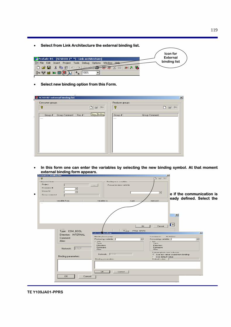
TE Y109JA01-PPRS
119
• Select from Link Architecture the external binding list.
• Select new binding option from this Form.
• In this form one can enter the variables by selecting the new binding symbol. At that moment
external binding form appears.
• Now one can only select the producer variable from the sending side if the communication is available and the definition of the producer variable has been already defined. Select the producing and consuming variable from the external binding form.
Icon for External
binding list
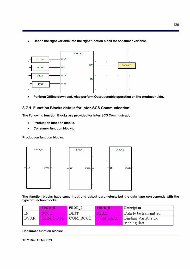
TE Y109JA01-PPRS
120
• Define the right variable into the right function block for consumer variable.
• Perform Offline download. Also perform Output enable operation on the producer side.
8.7.1 Function Blocks details for Inter-SCS Communication: The Following function Blocks are provided for Inter-SCS Communication:
• Production function blocks.
• Consumer function blocks.
Production function blocks:
The function blocks have same input and output parameters, but the data type corresponds with the type of function blocks.
Consumer function blocks:
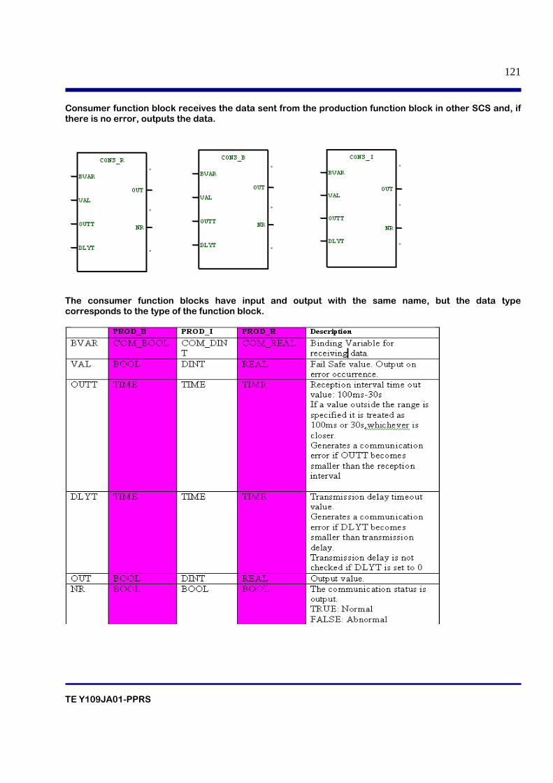
TE Y109JA01-PPRS
121
Consumer function block receives the data sent from the production function block in other SCS and, if there is no error, outputs the data.
The consumer function blocks have input and output with the same name, but the data type corresponds to the type of the function block.
TE Y109JA01-PPRS
122
09. SEQUENCE OF EVENT RECORDER
TE Y109JA01-PPRS
123
Table of contents 9.1 SOER Collection Definition
9.2 Event Collection
9.2.1 Objects of Event Collection
9.2.2 Event Saving
9.2.3 Event Targets
9.2.3.1 Events of Discrete Inputs (DI)
9.2.3.2 Events of Discrete Outputs (DO)
9.2.3.3 Events of Analog Inputs (AI)
9.2.3.4 Events of internal variables
9.3 Event Storage
9.3.1 Saving Event Data
9.3.2 Flow of Event Storage
9.3.3 Specification of Event Log Files
9.3.4 Trip Signal
9.3.5 Specification of Trip Signal Files
9.4 Management of Event Information when SCS is Unsteady
9.4.1 Protection of Event Information at Power Failure
9.4.2 SCS Startup Operation
9.4.3 Lock Status by the Forcing Function
9.5 SOE Viewer
9.5.1 SOE Viewer Window
9.5.2 Displaying SOE Viewer
9.5.3 Event Mode Operation
9.5.4 Activating the Event Mode
9.5.5 Data Source Query
9.5.6 Trip Mode Operation
9.5.7 Activating the Trip Mode
TE Y109JA01-PPRS
124
9.1 SOER Collection Definition Sequence of Events Recorder (SOER) is a function that collects and stores events occurred in an SCS. The SOER collection definition defines which events to collect. It also specifies the time synchronization method related to event collection time (time stamp). By using SOE Viewer, it is possible to analyze collected events and save them in files.
9.2 Event Collection The setting method of event collection definition varies depending on the object. Events can be collected either from a discrete input/output module or an application logic. 9.2.1 Objects of Event Collection The following types of events can be collected for SCSs. • Signal changes of discrete input modules. It is possible to collect events from discrete input modules according to the changes of data input from individual channels. Specify whether or not to collect events for each channel. • Signal changes of discrete output data It is possible to collect events according to the changes of data output to individual discrete output channels. Specify whether or not to collect events for each channel. • Alarms on Analog input data and Recovery It is possible to collect events by comparing the output values with the settings of alarm level set to the analog input block. • Variation of Analog output data It is possible to collect events based on the variation of output variable. Take the settings of the output variable into SOE_R, and specify the conditions of event generation. • Changes of internal variable of an application logic It is possible to collect events according to the changes of an internal variable of an application logic. Specify the object internal variable and conditions of event generation. 9.2.2 Event Saving • There is no need to prepare a PC for saving events or keep the power supply to an SENG on at all times, because event information is saved in the SCS. • The maximum number of event information records that can be saved in an SCS is 15,000. • It is possible to ensure that particularly important event information, i.e., records acquired before and after a trip signal was generated, can be notified to users without fail by separating the storage location.
TE Y109JA01-PPRS
125
9.2.3 Event Targets An SCS can save the following data as event information by user specification. Events related to discrete inputs (DI) are collected by the input modules; other events are collectedby the CPU. 9.2.3.1 Events of Discrete Inputs (DI) • Discrete input modules detect changes in the input signals input to each channel (FALSE to TRUE or TRUE to FALSE) and collect events. • Users can specify whether or not to collect SOE event information for each channel. • If discrete input modules are placed in redundant configuration, the active module collects events. • The each comment text applied to the variable corresponding to DI is added to the event (acharacter string of up to 32 single-byte characters or 16 double-byte characters). The user needs to define the variables corresponding to the contact inputs on the Workbench Dictionary View as the comments so as to identify the whereabouts of the occurred events. 9.2.3.2 Events of Discrete Outputs (DO) • The CPU detects changes in the output value set to a discrete output module and collects events. • Users can specify whether or not to collect SOE event information for each channel. • For dual-redundantly configured contact output modules, the signals output from the active module are gathered as the events. • If the output channel is abnormal (data status is BAD), the events will not be gathered. • Each event is attached with a comment text assigned as a variable to the contact output (a character string of up to 32 single-byte characters or 16 double-byte characters). The user needs to define the variables corresponding to the contact outputs on the Workbench Dictionary View as the comments so as to identify the events. 9.2.3.3 Events of Analog Inputs (AI) • The ANLG_S function block outputs alarms by judging analog input values, so it is able to collect events by making appropriate application. It performs magnitude correlation comparison of set values and analog output values (OUT) and collects events by using a change in OUT as a trigger. • Events are collected when the SOER input terminal is set to TRUE. • At event collection, a character string set to the ID input (a character string of up to 32 single- byte characters or 16 double-byte characters) is stored along with the event data.
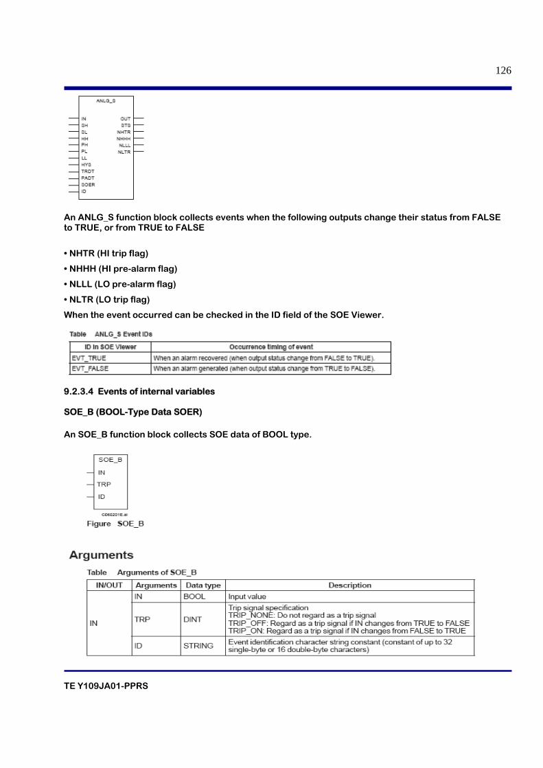
TE Y109JA01-PPRS
126
An ANLG_S function block collects events when the following outputs change their status from FALSE to TRUE, or from TRUE to FALSE
• NHTR (HI trip flag)
• NHHH (HI pre-alarm flag)
• NLLL (LO pre-alarm flag)
• NLTR (LO trip flag)
When the event occurred can be checked in the ID field of the SOE Viewer.
9.2.3.4 Events of internal variables SOE_B (BOOL-Type Data SOER) An SOE_B function block collects SOE data of BOOL type.
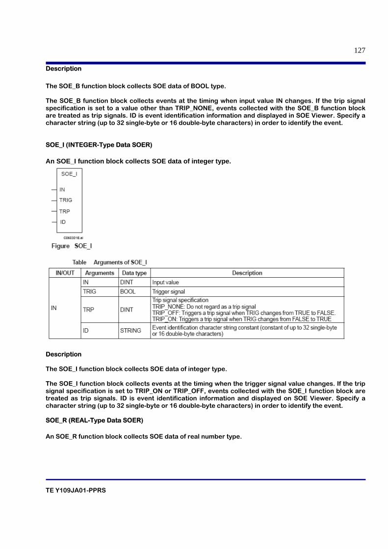
TE Y109JA01-PPRS
127
Description
The SOE_B function block collects SOE data of BOOL type. The SOE_B function block collects events at the timing when input value IN changes. If the trip signal specification is set to a value other than TRIP_NONE, events collected with the SOE_B function block are treated as trip signals. ID is event identification information and displayed in SOE Viewer. Specify a character string (up to 32 single-byte or 16 double-byte characters) in order to identify the event. SOE_I (INTEGER-Type Data SOER) An SOE_I function block collects SOE data of integer type.
Description The SOE_I function block collects SOE data of integer type. The SOE_I function block collects events at the timing when the trigger signal value changes. If the trip signal specification is set to TRIP_ON or TRIP_OFF, events collected with the SOE_I function block are treated as trip signals. ID is event identification information and displayed on SOE Viewer. Specify a character string (up to 32 single-byte or 16 double-byte characters) in order to identify the event. SOE_R (REAL-Type Data SOER) An SOE_R function block collects SOE data of real number type.
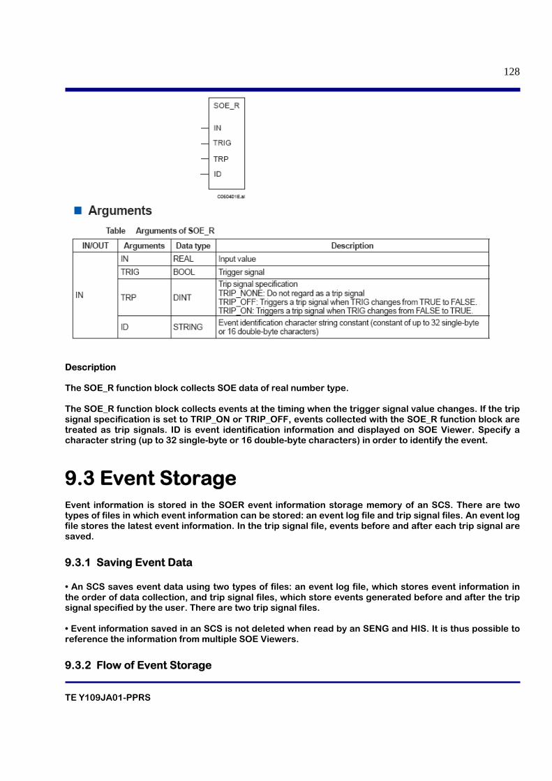
TE Y109JA01-PPRS
128
Description The SOE_R function block collects SOE data of real number type. The SOE_R function block collects events at the timing when the trigger signal value changes. If the trip signal specification is set to TRIP_ON or TRIP_OFF, events collected with the SOE_R function block are treated as trip signals. ID is event identification information and displayed on SOE Viewer. Specify a character string (up to 32 single-byte or 16 double-byte characters) in order to identify the event.
9.3 Event Storage Event information is stored in the SOER event information storage memory of an SCS. There are two types of files in which event information can be stored: an event log file and trip signal files. An event log file stores the latest event information. In the trip signal file, events before and after each trip signal are saved.
9.3.1 Saving Event Data • An SCS saves event data using two types of files: an event log file, which stores event information in the order of data collection, and trip signal files, which store events generated before and after the trip signal specified by the user. There are two trip signal files. • Event information saved in an SCS is not deleted when read by an SENG and HIS. It is thus possible to reference the information from multiple SOE Viewers.
9.3.2 Flow of Event Storage
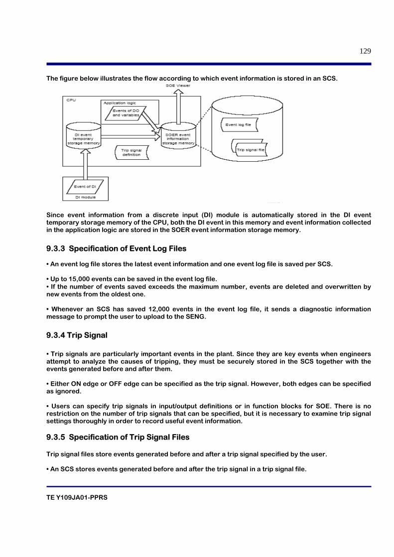
TE Y109JA01-PPRS
129
The figure below illustrates the flow according to which event information is stored in an SCS.
Since event information from a discrete input (DI) module is automatically stored in the DI event temporary storage memory of the CPU, both the DI event in this memory and event information collected in the application logic are stored in the SOER event information storage memory.
9.3.3 Specification of Event Log Files • An event log file stores the latest event information and one event log file is saved per SCS. • Up to 15,000 events can be saved in the event log file. • If the number of events saved exceeds the maximum number, events are deleted and overwritten by new events from the oldest one. • Whenever an SCS has saved 12,000 events in the event log file, it sends a diagnostic information message to prompt the user to upload to the SENG.
9.3.4 Trip Signal • Trip signals are particularly important events in the plant. Since they are key events when engineers attempt to analyze the causes of tripping, they must be securely stored in the SCS together with the events generated before and after them. • Either ON edge or OFF edge can be specified as the trip signal. However, both edges can be specified as ignored. • Users can specify trip signals in input/output definitions or in function blocks for SOE. There is no restriction on the number of trip signals that can be specified, but it is necessary to examine trip signal settings thoroughly in order to record useful event information. 9.3.5 Specification of Trip Signal Files Trip signal files store events generated before and after a trip signal specified by the user. • An SCS stores events generated before and after the trip signal in a trip signal file.
TE Y109JA01-PPRS
130
• A trip signal file stores 1,500 events in total: the last 500 events generated before tripping including the trip signal and the 1,000 events generated after tripping. • Up to two trip signal files can be stored in an SCS. No more trip signal files are saved even if more trip signals are generated. If two trips occur in a short period of time, the data in the two trip signal files may overlap. • If less than 500 events are collected prior a trip event occurs, the number of the events before the trip event will be less than 500. • The file will be closed when 1000 events are collected after the trip event. However,if the number of events after 30 minutes of the trip event is less than 1000, the file will be closed anyway with less events. • An SCS sends a diagnostic information message when saving of a trip signal file is completed. • Trip signal files are not automatically initialized by the system. These files can be initialized only via operation from the SENG.
9.4 Management of Event Information when SCS is Unsteady An SCS is considered to be unsteady if it is in one of the following conditions:
• A power failure occurs in the SCS
• During startup of the SCS
• Input/output variables are locked
If a power failure occurs in an SCS, event information is saved in a memory backed up by a battery. The SCS restores the event information at startup; it is thus possible to check the event information before the SCS was stopped. 9.4.1 Protection of Event Information at Power Failure Under normal circumstances, event information is stored in the main memory of an SCS. If a power failure occurs in the CPU, the data saved in the main memory is lost. Therefore, the SCS saves the most recent events recorded immediately before the power failure to a different memory backed up by a battery. Although all the events cannot be protected, it is possible to analyze events that occurred immediately before the power failure by protecting them in this way.
9.4.2 SCS Startup Operation An SCS restores the event information that was saved before it was stopped when it starts up at restarting or after off-line download.
9.4.3 Lock Status by the Forcing Function If input/output variables are locked by the forcing function, event collection is performed in the following ways when the values of the input/output variables change.
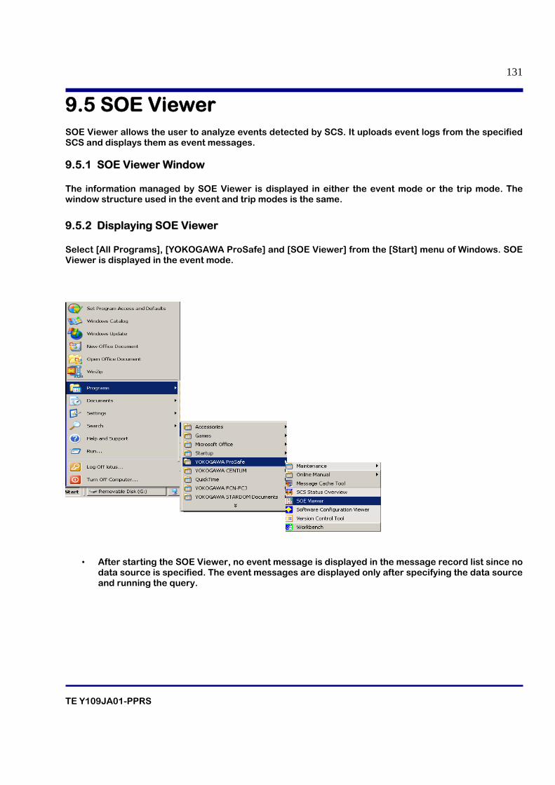
TE Y109JA01-PPRS
131
9.5 SOE Viewer SOE Viewer allows the user to analyze events detected by SCS. It uploads event logs from the specified SCS and displays them as event messages. 9.5.1 SOE Viewer Window The information managed by SOE Viewer is displayed in either the event mode or the trip mode. The window structure used in the event and trip modes is the same.
9.5.2 Displaying SOE Viewer Select [All Programs], [YOKOGAWA ProSafe] and [SOE Viewer] from the [Start] menu of Windows. SOE Viewer is displayed in the event mode.
• After starting the SOE Viewer, no event message is displayed in the message record list since no data source is specified. The event messages are displayed only after specifying the data source and running the query.
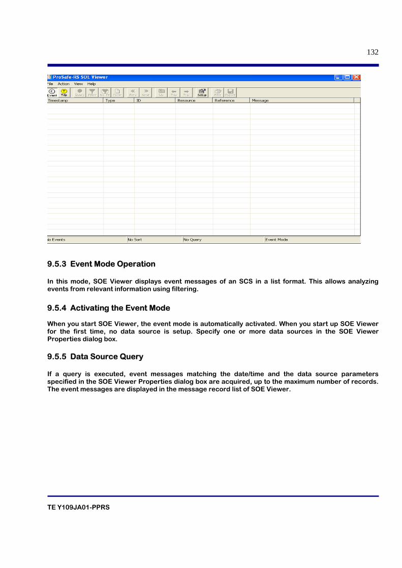
TE Y109JA01-PPRS
132
9.5.3 Event Mode Operation In this mode, SOE Viewer displays event messages of an SCS in a list format. This allows analyzing events from relevant information using filtering.
9.5.4 Activating the Event Mode When you start SOE Viewer, the event mode is automatically activated. When you start up SOE Viewer for the first time, no data source is setup. Specify one or more data sources in the SOE Viewer Properties dialog box. 9.5.5 Data Source Query If a query is executed, event messages matching the date/time and the data source parameters specified in the SOE Viewer Properties dialog box are acquired, up to the maximum number of records. The event messages are displayed in the message record list of SOE Viewer.
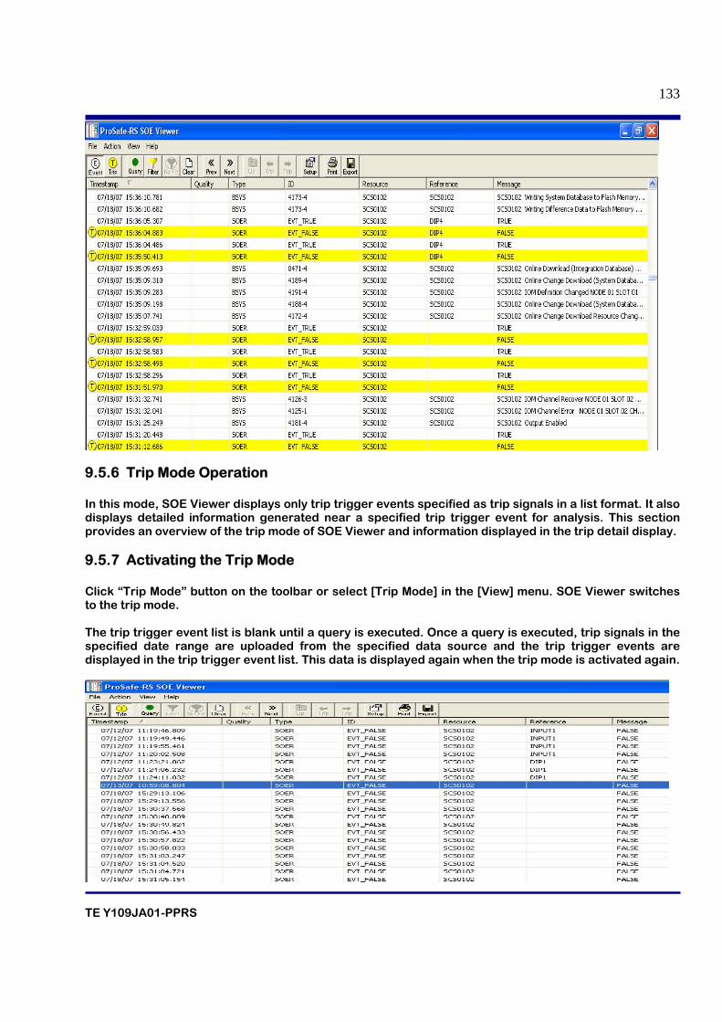
TE Y109JA01-PPRS
133
9.5.6 Trip Mode Operation In this mode, SOE Viewer displays only trip trigger events specified as trip signals in a list format. It also displays detailed information generated near a specified trip trigger event for analysis. This section provides an overview of the trip mode of SOE Viewer and information displayed in the trip detail display. 9.5.7 Activating the Trip Mode Click “Trip Mode” button on the toolbar or select [Trip Mode] in the [View] menu. SOE Viewer switches to the trip mode. The trip trigger event list is blank until a query is executed. Once a query is executed, trip signals in the specified date range are uploaded from the specified data source and the trip trigger events are displayed in the trip trigger event list. This data is displayed again when the trip mode is activated again.
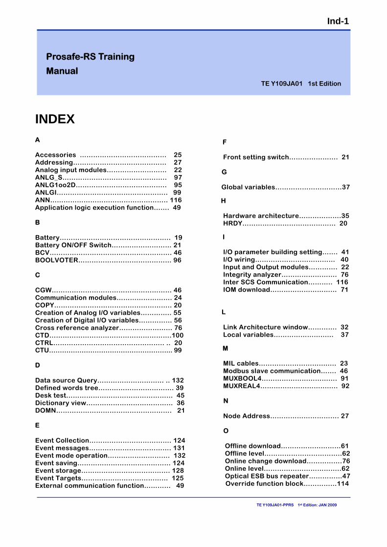
Ind-1
TE Y109JA01-PPRS 1st Edition: JAN 2009
INDEX A Accessories ………………………………… 25 Addressing…………………………………… 27 Analog input modules……………………… 22 ANLG_S……………………………………….. 97 ANLG1oo2D………………………………….. 95 ANLGI………………………………………….. 99 ANN…………………………………………….. 116 Application logic execution function……. 49 B Battery………………………………………….. 19 Battery ON/OFF Switch……………………… 21 BCV………………………………………………. 46 BOOLVOTER…………………………………… 96 C CGW……………………………………………… 46 Communication modules……………………. 24 COPY…………………………………………….. 20 Creation of Analog I/O variables………….. 55 Creation of Digital I/O variables…………… 56 Cross reference analyzer…………………... 76 CTD……………………………………………….100 CTRL………………………………………….. .. 20 CTU………………………………………………... 99 D Data source Query………………………... .. 132 Defined words tree……………………………. 39 Desk test………………………………………… 45 Dictionary view………………………………… 36 DOMN……………………………………………. 21 E Event Collection………………………………. 124 Event messages………………………………. 131 Event mode operation………………………. 132 Event saving…………………………………… 124 Event storage…………………………………. 128 Event Targets………………………………… 125 External communication function………… 49
F Front setting switch…………………. 21 G Global variables…………………………37
H Hardware architecture……………….35 HRDY…………………………………… 20
I I/O parameter building setting……. 41 I/O wiring……………………………… 40 Input and Output modules…………. 22 Integrity analyzer……………………. 76 Inter SCS Communication……….. 116 IOM download………………………… 71
L Link Architecture window…………. 32 Local variables…………………...... 37
M MIL cables………………………........ 23 Modbus slave communication……. 46 MUXBOOL4……………………………. 91 MUXREAL4………………………........ 92 N Node Address…………………………. 27 O Offline download………………………61 Offline level……………………………..62 Online change download…………….76 Online level……………………………..62 Optical ESB bus repeater……………47
Override function block……………114
Prosafe-RS Training
Manual TE Y109JA01 1st Edition
Ind-2
TE Y109JA01-PPRS 1st Edition: JAN 2009
P Parameter Tree……………………………… …38 Passwd…………………………………………..115 PORT……………………………………………….21 Pressure clamp terminals………………….. .24 Processor module………………………………19 Programming languages…………………….. 85 Project creation…………………………………51 Project template…………………………………51 R RCV…………………………………………………20 RDY…………………………………………………20 Reaction time…………………………………….08 Redundancy………………………………………..28 Relay boards……………………………………. 26 Reliability………………………………………… 08 Repeat Timer……………………………………. 94 S SAI143……………………………………………. 23 SAI533……………………………………………. 23 SAV144…………………………………………… 23 SB bus……………………………………………. 29 Scaler…………………………………………….. 93 Scan period……………………………………… 49 SCS database…………………………………… 66 SCS Maintenance support tool……………… 65 SCTY………………………………………………. 20 SEC401…………………………………………… 19 Serial communication modules………..….. 47 Signal cable interface adapter……………… 25 SNB10D……………………………………………22 SND……………………………………………….. 20 SOE_B………………………………… ….........126 SOE_I……………………………………………..127 SOE_R…………………………………………….127 SOER Collection Definition………………….124 SSC10D……………………………………………16 STA…………………………………………………21 Standard Type Safety control unit………….17 START/STOP……………………………………..21 STBY………………………………………………. 21 SYNC…………………………………………...... 20
T Tagname builder……………………………….112 Time synchronization…………………………..50 Trip mode………………………………………..133 Trip trigger event………………………………133 U User defined function block…………………101
V Variable bindings…………………………..34 Variable groups…………………………… 34 Variable tree………………………………. 37 VEL…………………………………………... 99 V-net coupler unit………………………....19 W Wiring check adapter………………….....26
i
TE Y109JA01-PPRS 1st Edition: Jan 2009
Revision Information
Title : PROSAFE-RS Training manual Manual No. : TE Y109JA01-PPRS JAN 2009 /1st Edition/R1.00 or later Newly published
Written by Training centre Customer Service Division Yokogawa India Limited