Embed Size (px)
Citation preview

Design, Analysis, and Prototyping of A 3×PPRS Parallel Kinematic Mechanism for meso-Milling
by
Guan Lei Zhao
A thesis submitted in conformity with the requirements
for the degree of Master of Applied Science
Department of Mechanical and Industrial Engineering
University of Toronto
@ Copyright by Guan Lei Zhao 2013

ii
Design, Analysis, and Prototyping of A 3×PPRS Parallel
Kinematic Mechanism for meso-Milling
Guan Lei Zhao
Master of Applied Science
Department of Mechanical and Industrial Engineering
University of Toronto
2013
Abstract
Parallel Kinematic Mechanisms (PKMs) are well suited for high-accuracy applications such as
meso-milling. However, drawbacks such as limited platform tilting angle and high configuration
dependency of stiffness often limit their usage. In this Thesis, a new six degree-of-freedom (dof)
PKM architecture based on a 3×PPRS topology is proposed, in order to address these problems.
The new PKM is presented, and its inverse kinematics and Jocobian matrix are derived. The
kinematic relations are incorporated into MATLAB to calculate the workspace of the PKM. The
stiffness of the new PKM is obtained using Finite Element Analysis (FEA), and configuration
dependency of stiffness is investigated. The proposed new mechanism is compared with three
similar existing 6-dof PKMs, and it is shown that the new PKM exhibits higher stiffness. Lastly,
three meso-Milling Machine Tool prototypes were designed and built. In particular, Prototype III
is based on the new mechanism.

iii
Acknowledgments
I would like to express my gratitude to my supervisors, Professor B. Benhabib and Professor J. K.
Mills for giving me the opportunity to participate in this research project, as well as their
continuous guidance and support.
I would like to thank my colleagues and friends from the Computer-Integrated-Manufacturing
Laboratory for their insight and inspiration: Mr. Hay Azulay, Mr. Masih Mahmoodi, Mr. Adam
Le, and Mr. Ashish Macwan.
I would like to acknowledge NSERC for providing the funding to make the CANRIMT project
and my research possible.
I would also like to acknowledge Promation Engineering Ltd. for their support and advice.
Finally, I would like to thank my parents for their support and encouragement.

iv
Table of Contents
Acknowledgments .................................................................................................................. iii
Table of Contents ................................................................................................................... iv
List of Tables ....................................................................................................................... viii
List of Figures ........................................................................................................................ ix
List of Appendices................................................................................................................ xiii
Nomenclature and Acronyms ................................................................................................ xiv
Chapter 1 Introduction and Literature Review ..................................................................... 1
1.1 Introduction ............................................................................................................... 1
1.2 Overview of PKM Based 5-axis Machine Tool Designs .............................................. 2
1.3 Reference Parallel Kinematic Mechanisms ................................................................. 6
1.4 Thesis Objective ........................................................................................................ 7
1.5 Organization of Thesis ............................................................................................... 8
Chapter 2 Design ................................................................................................................ 9
2.1 Architecture............................................................................................................... 9
2.2 Kinematic Modeling ................................................................................................ 10
2.2.1 Notation ........................................................................................................... 10
2.2.2 Inverse Kinematics ........................................................................................... 11
2.2.3 Inverse Jacobian Matrix .................................................................................... 12
Chapter 3 Analysis ........................................................................................................... 14
3.1 Workspace and Platform Tilting Angle ..................................................................... 14
3.1.1 Definition ......................................................................................................... 14
3.1.2 Method............................................................................................................. 15

v
3.1.3 Geometrical Study ............................................................................................ 15
3.1.3.1 Geometrical dimensions and constraints...................................................... 16
3.1.3.2 Curvilinear rail radius................................................................................. 17
3.1.3.3 Link length ................................................................................................ 18
3.1.3.4 Platform size.............................................................................................. 19
3.1.3.5 Link length and platform size ..................................................................... 20
3.1.3.6 Minimum curvilinear joint separation ......................................................... 21
3.1.3.7 Prismatic joint travel .................................................................................. 22
3.1.3.8 Spherical joint angle of swing..................................................................... 23
3.1.3.9 Summary ................................................................................................... 24
3.1.4 Singularities ..................................................................................................... 24
3.2 Dynamic Stiffness.................................................................................................... 26
3.2.1 Configuration Dependency of Dynamic Stiffness ............................................... 27
3.2.2 Summary .......................................................................................................... 31
3.3 Comparative Analysis .............................................................................................. 32
3.3.1 Platform Tilting Angle ...................................................................................... 34
3.3.2 Stiffness ........................................................................................................... 35
3.3.3 Summary .......................................................................................................... 40
Chapter 4 Prototype .......................................................................................................... 43
4.1 Prototype I............................................................................................................... 44
4.1.1 Mechanical Design ........................................................................................... 45
4.1.1.1 Base .......................................................................................................... 45
4.1.1.2 Links ......................................................................................................... 45

vi
4.1.1.3 Mobile P latform......................................................................................... 46
4.1.1.4 Adaptor ..................................................................................................... 47
4.1.2 Weight ............................................................................................................. 48
4.1.3 Stiffness ........................................................................................................... 48
4.1.4 Prototype Built ................................................................................................. 49
4.2 Prototype II ............................................................................................................. 50
4.2.1 Mechanical Design ........................................................................................... 51
4.2.1.1 Base .......................................................................................................... 51
4.2.1.2 Links ......................................................................................................... 51
4.2.1.3 Mobile P latform......................................................................................... 52
4.2.1.4 Adaptors .................................................................................................... 52
4.2.2 Stiffness ........................................................................................................... 53
4.2.3 Weight ............................................................................................................. 53
4.2.4 Prototype Built ................................................................................................. 54
4.3 Prototype III ............................................................................................................ 55
4.3.1 Mechanical Design ........................................................................................... 57
4.3.1.1 Base .......................................................................................................... 57
4.3.1.2 Links ......................................................................................................... 58
4.3.1.3 Mobile P latform......................................................................................... 58
4.3.2 Stiffness ........................................................................................................... 59
4.3.3 Weight ............................................................................................................. 59
4.3.4 Prototype Built ................................................................................................. 60
4.4 Actuators and Passive Joints ..................................................................................... 61

vii
4.4.1 Linear Actuator................................................................................................. 61
4.4.2 Curvilinear Guide Rail and Slider ...................................................................... 62
4.4.3 Revolute Joint Assembly................................................................................... 63
4.4.4 Spherical Joint .................................................................................................. 64
4.5 Machining Experiments ........................................................................................... 65
4.5.1 Spindle Assembly ............................................................................................. 66
4.5.2 Workpiece ........................................................................................................ 67
4.5.3 Workpiece Holder Assembly............................................................................. 67
4.5.4 Tool Path.......................................................................................................... 67
4.5.5 Results ............................................................................................................. 68
4.6 Summary ................................................................................................................. 69
Chapter 5 Conclusions and Future Research ...................................................................... 70
5.1 Conclusions ............................................................................................................. 70
5.2 Future Work ............................................................................................................ 71
References ............................................................................................................................ 72
Appendix A – Measuring Tilting Angle with CAD ................................................................. 78
Appendix B – Engineering Drawings for Prototype I .............................................................. 80
Appendix C – Engineering Drawings for Prototype II ............................................................. 84
Appendix D – Engineering Drawings for Prototype III............................................................ 86
Appendix E – Engineering Drawings of the Revolute Joint Assembly ..................................... 89
Appendix F – Inverse Kinematics of the 9-dof Redundant RmMT........................................... 92

viii
List of Tables
Table 3.1: Geometrical dimensions and constraints – default values. ....................................... 17
Table 3.2: Geometrical dimensions and constraints. ................................................................ 24
Table 3.3: Minimum dynamic stiffness for 5 different PKM configurations. ............................ 31
Table 3.4: Geometrical parameters and kinematic constraints of the PKMs. ............................. 34
Table 3.5: PKMs’ stiffnesses for Configuration 1.................................................................... 40
Table 3.6: PKMs’ stiffnesses for Configuration 2.................................................................... 40
Table 3.7: PKMs’ stiffnesses for Configuration 3.................................................................... 40

ix
List of Figures
Figure 1.1: The Hexapod 380 by CMW. ................................................................................... 3
Figure 1.2: The Tricenter by Deckel Maho. .............................................................................. 4
Figure 1.3: The Pentapod machine by Metrom. ......................................................................... 4
Figure 1.4: The Ecospeed by DS-Technology. .......................................................................... 5
Figure 1.5: The Eclipse. ........................................................................................................... 6
Figure 1.6: Reference PKMs: (a) the Alizade PKM, (b) the Eclipse (c) the Glozman PKM. ....... 6
Figure 1.7: Similar mechanisms to Reference PKMs: (a) the Behi mechanism, (b) the
Tahmasebi mechanism, (c) the Ben-horin mechanism. .............................................................. 7
Figure 2.1: The New PKM architecture. ................................................................................... 9
Figure 2.2: Kinematic notation for the new PKM. ................................................................... 10
Figure 3.1: Reachable positions and platform tilting angle....................................................... 15
Figure 3.2: Geometrical study (a) top half of a spherical surface, (b) cross-section of the top half
of a spherical surface. ............................................................................................................ 16
Figure 3.3: Platform tilting angle vs curvilinear rail radius. ..................................................... 17
Figure 3.4: Spherical workpiece’s height vs link length. .......................................................... 18
Figure 3.5: Height of the spherical workpiece vs link length. ................................................... 19
Figure 3.6: Platform tilting angle vs link length. ...................................................................... 19
Figure 3.7: Platform tilting angle vs platform size. .................................................................. 20
Figure 3.8: Platform tilting angle vs platform size and link length. ........................................... 21
Figure 3.9: Minimum curvilinear joint separation. .................................................................. 21
Figure 3.10: P latform tilting angle vs minimum curvilinear joint separation. ............................ 22
Figure 3.11: P latform tilting angle vs prismatic joint range of travel. ....................................... 22
x
Figure 3.12: Spherical joint. ................................................................................................... 23
Figure 3.13: P latform tilting angle vs spherical joint angle of swing. ....................................... 23
Figure 3.14: Singular positions within the workspace (a) perspective view, (b) top view. ......... 26
Figure 3.15: PKM configurations for stiffness analysis (a) Configuration 1,
(b) Configuration 2, (c) Configuration 3, (d) Configuration 4, and (e) Configuration 5. ....... 28
Figure 3.16: FEA simulation environment. ............................................................................. 29
Figure 3.17: FRF for different PKM configurations along (a) xx, (b) yy, and
(c) zz directions, respectively............................................................................................. 30
Figure 3.18: Compared PKMs (a) the new PKM, (b) the Eclipse, (c) the Alizade PKM, and,
(d) the Glozman PKM. ...................................................................................................... 33
Figure 3.19: Maximum platform tilting angle for the compared PKMs. ................................... 34
Figure 3.20: Configuration 1 (a) the new PKM, (b) the Eclipse, (c) the Alizade PKM, and,
(d) the Glozman PKM. ...................................................................................................... 35
Figure 3.21: Configuration 3 (a) the new PKM, (b) the Eclipse, (c) the Alizade PKM, and,
(d) the Glozman PKM. ...................................................................................................... 36
Figure 3.22: Configuration 1 - FRF for all the PKMs along (a) xx, (b) yy, and
(c) zz directions................................................................................................................. 37
Figure 3.23: Configuration 1 - FRF for all the PKMs excluding the Glozman PKM. ................ 37
Figure 3.24: Configuration 2 - FRF for all the PKMs along (a) xx, (b) yy, and
(c) zz directions................................................................................................................. 38
Figure 3.25: Configuration 3 - FRF for all the PKMs along (a) xx, (b) yy, and
(c) zz directions................................................................................................................. 39
Figure 3.26: Configuration 3 - FRF for all the PKMs excluding the Glozman PKM. ................ 39

xi
Figure 4.1: CAD model of Prototype I. ................................................................................... 44
Figure 4.2: Base design of Prototype I. ................................................................................... 45
Figure 4.3: Link design of Prototype I. ................................................................................... 46
Figure 4.4: Mobile platform design of Prototype I................................................................... 47
Figure 4.5: Adaptor design of Prototype I. .............................................................................. 47
Figure 4.6: The built Prototype I. ........................................................................................... 50
Figure 4.7: CAD design of Prototype II. ................................................................................. 51
Figure 4.8: Link design of Prototype II. .................................................................................. 52
Figure 4.9: Adaptor design for Prototype II............................................................................. 53
Figure 4.10: The built Prototype II. ........................................................................................ 55
Figure 4.11: CAD design of Prototype III. .............................................................................. 56
Figure 4.12: RmMT prototype with its sliders locked on the curvilinear guide. ........................ 57
Figure 4.13: Base design of Prototype III................................................................................ 58
Figure 4.14: Link design of Prototype III. ............................................................................... 58
Figure 4.15: P latform design of Prototype III. ......................................................................... 59
Figure 4.16: The built RmMT prototype. ................................................................................ 61
Figure 4.17: Nanomotion FB075 linear actuator...................................................................... 62
Figure 4.18: THK HCR 15A+60/150R curvilinear guide. ........................................................ 63
Figure 4.19: Cross-section of the revolute joint assembly. ....................................................... 64
Figure 4.20: Seiko Hephaist SRJ008C spherical joint. ............................................................. 65
Figure 4.21: Machining experimental setup. ........................................................................... 66
Figure 4.22: Tool path for the letter “U”. ................................................................................ 68
Figure 4.23: A machining experiment. .................................................................................... 68
xii
Figure A.1: Measuring platform tilting angle on CAD............................................................. 78
Figure A.2: Solid model representation for spherical joint angle of swing. ............................... 79
Figure B.1: Engineering drawing of the base. ......................................................................... 80
Figure B.2: Engineering drawing of the link. .......................................................................... 81
Figure B.3: Engineering drawing of the mobile platform ......................................................... 82
Figure B.4: Engineering drawing of the adaptor.. .................................................................... 83
Figure C.1: Engineering drawing of the link.. ......................................................................... 84
Figure C.2: Engineering drawing of the adaptor.. .................................................................... 85
Figure D.1: Engineering drawing of the base.. ........................................................................ 86
Figure D.2: Engineering drawing of the link.. ......................................................................... 87
Figure D.3: Engineering drawing of the mobile platform.. ....................................................... 88
Figure E.1: Engineering drawing of the central housing.. ........................................................ 89
Figure E.2: Engineering drawing of the side housing............................................................... 90
Figure E.3: Engineering drawing of the shaft.. ........................................................................ 91
Figure F.1: Schematics of the 9-dof Redundant RmMT.. ......................................................... 92

xiii
List of Appendices
Appendix A: Measuring Tilting Angle with CAD.. ................................................................. 78
Appendix B: Engineering Drawings for Prototype I.. .............................................................. 80
Appendix C: Engineering Drawings for Prototype II.. ............................................................. 84
Appendix D: Engineering Drawings for Prototype III.. ........................................................... 86
Appendix E: Engineering Drawings of the Revolute Joint Assembly.. ..................................... 89
Appendix F: Inverse Kinematics of the 9-dof Redundant RmMT............................................. 92

xiv
Nomenclature and Acronyms
Nomenclature
Latin Letters
Position of curvilinear base joint
Position of radial prismatic joint
Radial prismatic joint travel
Tangential prismatic joint travel or RmMT
Radial prismatic joint travel for RmMT
Mobile platform frame at center of the platform
Transformation matrix from to
Inverse Jacobian Matrix
Inverse Jacobian matrix of Euler angles
Kinematic inverse Jacobian Matrix
Determinant of the kinematic inverse Jacobian Matrix
Link length
First actuator
Second actuator
Global frame at center of the circular rail
Position of spherical joints
Joint-space coordinates
Velocity in joint-space coordinates

xv
Radius of the c ircular rail
Radius of the mobile platform
Rotation matrix in
Task-space coordinates
Velocity in task-space coordinates
Greek Letters
Euler angles
Curvilinear joint travel
Angle between two curvilinear joints
Revolute joint travel
Acronyms
3D 3-Dimensional
CAD Computer-aided design
dof Degree-of-freedom
FEA Finite element analysis
FRF Frequency response function
IKP Inverse kinematic problem
mMT meso-Milling Machine Tool
P Prismatic joint

xvi
PCP Platform center point
PID Proportional-integral-derivative
PKM Parallel Kinematic Mechanism
PWM Pulse-width modulation
RmMT Reconfigurable meso-Milling Machine Tool
R Revolute joint
S Spherical joint

1
Chapter 1 Introduction and Literature Review
1.1 Introduction
The term meso-Milling commonly refers to the machining of parts within the dimensional range
of 0.5 to 5 mm, feature sizes of less than 0.1 mm, and tolerances of less than ±1µm. In recent
years, miniaturized 3D sculpted parts with complex features, producible on such machines, are
increasingly in demand in various industries, such as biomedical, aerospace, consumer
electronics, and defense [1].
Compared to conventional size machine tools, smaller-scale meso-Milling Machine Tools
(mMTs) offer several advantages, such as smaller footprint, less energy consumption, and less
cost [2]. Currently, there are several mMTs that can mill parts in the range of millimeters or less.
For instance, the MesoMill developed by MIT Precision Engineering Research Group [3] can
machine parts in the range 6 to 25mm. The overall size of this machine is 750×400×300 mm.
Current research efforts are mostly focused on the design of mMTs based on serial kinematic
mechanisms (e.g., [4], [5], [6], [7]). For serial kinematic mechanisms, the feed stages are stacked
one upon another, which means the overall stiffness of the machine at the tooltip is determined
by the least stiff structural component, and that positioning errors are accumulated [8].
In response, Parallel Kinematic Mechanisms (PKMs) have attracted considerable attention from
both researchers and manufacturers over the past two decades. A PKM is a closed-loop
kinematic chain mechanism whose end-effector is linked to the base by independent kinematic
chains [8]. PKMs are well suited for high-accuracy applications, such as motion simulators [9],
coordinate measuring machines [10], surgery robots [11], micro-positioning systems [12] and
machine tools [13].
The main advantage of PKMs is their increased positioning accuracy compared to serial
kinematic mechanisms, due to their high overall stiffness. This characteristic of PKMs can be
explained by the fact that the forces in the mechanisms are mainly acted along the kinematic
2
chains, which have very high stiffness in compression and tension. Also, the forces are
distributed among the kinematic chains, as they are connected in parallel, which avoid error
build-up [14]. Moreover, PKMs can be designed to have their actuators mounted at the base,
which lowers the moving mass and allow for high operational speed [15].
However, there are several challenges in the design of 5-axis mMTs using PKMs, such as
relatively small workspace coverage [16] and limited end-effector/tool platform tilting angle [17].
For example, while following a continuous path on a 3D surface, the platform tilting angle of
most PKMs cannot reach 90°, which is a fundamental requirement for full 5-axis milling
operations. Furthermore, PKMs that can achieve 90° platform tilting angle often do not satisfy
the required stiffness for milling operations [18]. Lastly, the performance of a PKM is highly
pose dependent, namely, there is a large variation of performance within its workspace [14].
To address these problems, several approaches have been proposed. One approach is to design
hybrid mechanisms, which is the combination of serial and parallel mechanisms [19]. However,
it is not a first priority design option in this research, since it would have lower stiffness than its
PKM counterparts. Another approach is to incorporate redundant degrees-of-freedom (dof) into
the mechanism, namely, using more actuators than the required platform dof [20] [21]. The
added redundancy can allow for more machine configurations, which can be utilized to improve
machine performance (i.e., platform tilting angle) through optimization. Lastly, the third
approach is to design novel PKM architectures with enhanced performance.
1.2 Overview of PKM Based 5-axis Machine Tool Designs
Several PKM based machine-tool concepts have been realized in the past. However, there is no
existing PKM-based mMT design. Therefore, this literature review will provide an overview of
conventional size PKM-based machine tool designs, and brief discussion of their performance
criteria.
In the context of machine-tool applications, most known prototypes of commercial PKMs can be
categorized into two families: (i) PKMs with fixed base joints and length varying struts, and (ii)
PKMs with moving base joints and fixed length struts [22]. It can be noted that redundancies and

3
hybrids are extensively employed in the realized designs. It is also to be noted that these designs
generally have a positioning accuracy of 3µm or worse [14]
The first family comprises machine-tool designs which are derived from the Gough-Stewart
platform architecture. The Gough-Stewart platform has six prismatic actuators, and the actuators
are connected to the base and the platform, usually through universal joints. One notable
weakness of the Gough-Stewart platform is its low platform tilting angle [23].
This family of PKM-based machine tools includes the Hexapod 380 by CMW, as shown in
Figure 1.1 [24]. It is a 5-axis milling machine tool for machining large parts used in nuclear and
aerospace industry. It has a classical Stewart-platform architecture, and can machine parts with a
positioning accuracy of 8µm. It has a platform tilting angle of ±30°.
Figure 1.1: The Hexapod 380 by CMW.
One way to improve platform tilting angle is to employ a hybrid mechanism into the machine
design. For example, the Tricenter by Deckel Maho [25] is a 5-axis hybrid mechanism milling
machine, as shown in Figure 1.2. This design is specially focused on tool dexterity. The machine
has three actuators arranged in parallel to control x , y, and z motions of the central platform,
which carries a two-axis serial milling heads. This hybrid mechanism milling machine is able to
achieve ±60° platform tilting in x-axis, and ±90° in z-axis.

4
Figure 1.2: The Tricenter by Deckel Maho.
In another attempt to overcome limitation in platform tilt, the company Metrom developed a
Pentapod based machine [26], as shown in Figure 1.3, which has five extensible struts carrying
the platform. The kinematics has been configured so that in one tool axis, the platform is able to
achieve 90° tilting angle. However, in order to achieve full 5-axis machining, a redundant rotary
table needs to be incorporated in serial to the Pentapod, which makes it a hybrid mechanism.
Figure 1.3: The Pentapod machine by Metrom.
Similar PKM based machine tools in this family include the VARIAX-Hexacenter by Gidding &
Lewis, the TORNADO 2000 by Hexel, and the MIKROMAT 6X (Mikromat/IWU) [22].

5
The second family of PKMs have been investigated more recently: This category includes the
Ecospeed [14] by DS-Technology, as shown in Figure 1.4. It is specifically designed for high
speed machining of structural aircraft components from aluminum alloy plate and billet type
materials. The machine is developed as a hybrid system, its rotary and z-axes are fully parallel,
and are carried by the serial x- and y-stages. The machine has a platform tilting angle of ±40°,
and a stiffness of 55N/µm, 50N/µm and 250/µm in x , y, and z direction, respectively.
Figure 1.4: The Ecospeed by DS-Technology.
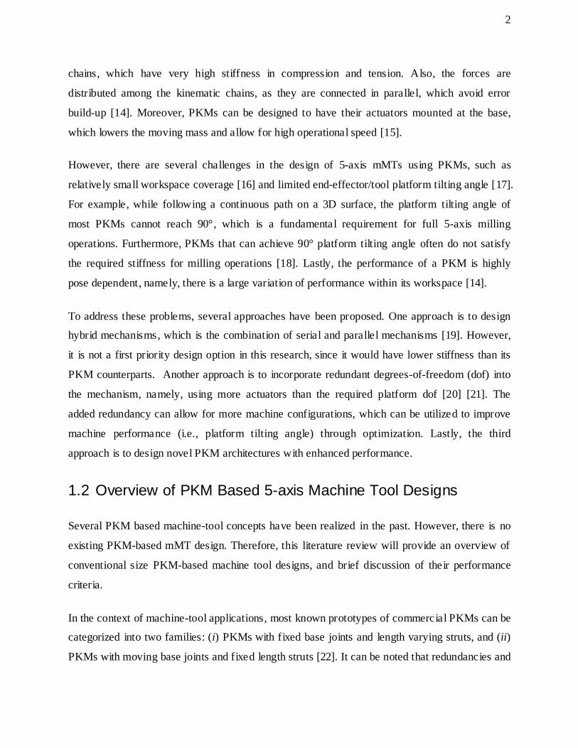
The Eclipse, shown in Figure 1.5, deserves special mention [17]. It is a redundant 5-axis machine
with three kinematic chains , and has a 3×PPRS topology. The Eclipse stands out from all the
existing PKM based machine tools, as it is the only fully parallel 5-axis machine tool which can
achieve 90° platform tilting angle. In fact, a first effort in our laboratory in designing a new
mMT was based on downsizing the Eclipse mechanism [18]. Although new approaches were
needed due to its insufficient stiffness, the Eclipse does provide an excellent reference for this
research.
Other PKM based machine tools that belong to the second family include the HexaM by Toyota,
the Urane SX by Renault Automation, and the Quickstep by Krause & Mauser [22].
6
Figure 1.5: The Eclipse.
1.3 Reference Parallel Kinematic Mechanisms
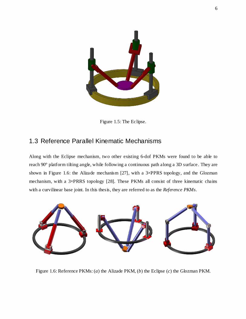
Along with the Eclipse mechanism, two other existing 6-dof PKMs were found to be able to
reach 90° platform tilting angle, while following a continuous path along a 3D surface. They are
shown in Figure 1.6: the Alizade mechanism [27], with a 3×PPRS topology, and the Glozman
mechanism, with a 3×PRRS topology [28]. These PKMs all consist of three kinematic chains
with a curvilinear base joint. In this thesis, they are referred to as the Reference PKMs.
Figure 1.6: Reference PKMs: (a) the Alizade PKM, (b) the Eclipse (c) the Glozman PKM.
(a) (b) (c)

7
It is to be noted, that there are other three 6-dof PKMs which are similar to the Reference PKMs,
as shown in Figure 1.7: the Behi mechanism with a 3×PPRS topology [29], the Tahmasebi
mechanism with a 3×PPUU topology [30], and the Ben-horin mechanism with a 3×PPRS
topology [31]. The Behi mechanism is similar to the Alizade mechanism, and its base joint can
be sliding on either a triangular or a rectangular rail. For Tahmasebi and Ben-horin mechanisms,
there is an x-y motion stage in each of the base joints, and the base joints can be fixed at different
locations on a plane.
It is shown that these mechanisms can achieve 90° platform tilting angle. However, since each of
the base joints in these PKMs only has linear motion with a limited range of travel, their
workspace coverage is substantially smaller than the Reference PKMs when examined using
similar geometrical design parameters and are, therefore, excluded from the Reference PKMs list.
Figure 1.7: Similar mechanisms to Reference PKMs: (a) the Behi mechanism, (b) the
Tahmasebi mechanism, (c) the Ben-horin mechanism.
1.4 Thesis Objective
From the literature review, it is seen that there currently exists no PKM-based mMT design, so
an overview of conventional size parallel machine tools was provided. Investigating
conventional size machine tools, it was found that existing PKM-based machine tools suffer
from two major drawbacks: (i) limited range of platform tilting angle (e.g., the Hexapod), and (ii)
low structural stiffness, which leads to inaccuracy at the tooltip (e.g., the Eclipse).
(a) (b) (c)

8
Therefore, the objective of this thesis is to develop a new Parallel Kinematic Mechanism, which
is suitable for 5-axis meso-Milling Machine Tool design. The PKM needs to satisfy the
following requirements:
1. Ability to reach at least 90° platform tilting angle , while following a continuous path on a
3D surface.
2. Among all the possible PKMs which meet the first requirement, the new PKM needs to
attain the highest stiffness.
1.5 Organization of Thesis
The remainder of the thesis is organized as follows:
Chapter 2 presents the architecture and kinematic modelling of the new PKM. In particular, the
inverse kinematics and the Jacobian matrices are derived.
Chapter 3 is divided into three sections. Section 3.1 analyzes the new PKM’s workspace and
platform tilting angle. The workspace is defined with respect to the PKM’s platform tilting angle ,
and the effect of geometrical design parameters on the platform tilting angle is investigated.
Section 3.1 concludes with a brief discussion on singularity within the new PKM’s workspace.
Section 3.2 discusses the new PKM’s stiffness, as well as its configuration dependency. Lastly,
Section 3.3 presents a comparative analysis of the new PKM and the Reference PKMs.
Chapter 4 describes three built RmMT prototype, as well as their respective mechanical designs.
The built reconfigurable mMT prototypes are redundant mechanisms and have 9-dof, and are
utilized as test beds for integrating subcomponents and conducting physical experiments.

9
Chapter 2 Design
In this Chapter, the architecture of the proposed new PKM is presented. Its inverse kinematic
model, which describes the relationship between the position and orientation (pose) of the mobile
platform and the positions of the actuated joints, is derived. Also, the inverse kinematic Jacobin
matrix is obtained. These kinematic relations will be used to investigate workspace and platform
tilting angle in Chapter 3.
2.1 Architecture
The new PKM, which is shown in Figure 2.1, has a 3×PPRS topology (the underline indicates
the actuated joints). It has three identical kinematic chains that connect the mobile platform to
the stationary circular rail. Each chain has two actuators, which are drawn in red. denotes the
first actuator, which moves along the circular rail. The second actuator, denoted as , is
mounted on top of , and it moves in radial direction with respect to the circular rail. A fixed-
length link is connected to the second actuator, , through a revolute joint, and the mobile
platform is connected to the link through a spherical joint.
Figure 2.1: The New PKM architecture.

10
2.2 Kinematic Modeling
2.2.1 Notation
Figure 2.2 shows the schematic representation of the new PKM. The mechanism consists of a
circular rail with radius , and the global coordinate frame is positioned at its center point.
Three actuated curvilinear joints are attached on top of the circular rail, and the position of the
curvilinear joint on the ( =1 to 3) kinematic chain is denoted as . Then,
three actuated prismatic joints which travel in radial direction with respect to the circular rail are
mounted on top of the curvilinear joints, and they are located at . Next,
three links of fixed length, , connect the prismatic joints and the mobile platform through
passive revolute and spherical joints, respectively. The revolute joints have an angular travel of
. The spherical joints are located 120° apart on a mobile platform with radius , and their
positions are denoted as .
Figure 2.2: Kinematic notation for the new PKM.
The joint-space coordinates of the active joints are defined by the vector
, where represents the curvilinear joint travel, and represents
the prismatic joint travel, respectively. The mobile frame, , is attached at the center of the

11
platform, and its z-axis is normal to the platform. In this Thesis, the pose of the mobile platform
is described by its center point position, and three Euler angles representing t he orientation of the
mobile frame, , with respect to the base frame, . The minimum number of independent
coordinates describing the pose of a 6-dof mobile platform is six, which is denoted here as
.
2.2.2 Inverse Kinematics
The inverse kinematics problem (IKP) of a PKM describes the mapping from the pose of its
mobile platform, , to the joint-space coordinates, . IKP is relatively straightforward to solve,
as the actuated joint-space variables can be expressed explicitly in terms of task-space variables
[8]. The purpose of solving IKP is to use the relationships in subsequent analyses. One way of
using inverse kinematics relations is to verify whether a given coordinate point can be reached
by the PKM, and by checking every point in a predefined volume (e.g., the volume of a sphere),
the PKM’s workspace size and platform tilting angle can be derived. Also, inverse kinematics
can be employed to determine the system inverse Jacobian, which can be used in singularity
calculation.
To solve the IKP of the new PKM, first, the positions of the spherical joints ( 1 to 3) with
respect to the mobile frame, , are calculated:
, (2.1)
, and (2.2)
. (2.3)
Then, the position of each spherical joint, with respect to global frame, , is defined by
, (2.4)

12
where is the position of the spherical joints given in task-space coordinates. is the
rotation matrix of the mobile platform with respect to global frame. From here, the joint-space
coordinates of the PKM in terms of position of the spherical joints, , can be expressed as:
, (2.5)
(2.6)
. (2.7)
Given Equations (2.1) to (2.7), the positions of the actuated curvilinear and prismatic joints can
be obtained as:
, and (2.8)
. (2.9)
2.2.3 Inverse Jacobian Matrix
The inverse Jacobian matrix is defined here as the matrix relating the velocity of the mobile
platform to the velocities of the actuated joints:
. (2.10)
There are two types of inverse Jacobian matrix, depending on how is defined. The first type is
the kinematic inverse Jacobian matrix ( ), which relates the mobile platform’s linear and
angular velocities to the actuated joints’ velocities. The second type is the inverse Jacobian
matrix of Euler angles ( ), which relates the mobile platform’s linear velocity and the
variations of the Euler angles to the actuated joints velocities [16]. Since is defined with
respect to its Euler angles variations, the inverse Jacobian matrix of Euler angle can be calculated
as:

13
(2.11)
Moreover, the kinematic inverse Jacobian matrix is needed for singularity analysis, and can be
obtained from the inverse Jacobian matrix of Euler angles through a simple matrix
transformation, [8]:
, (2.12)
where
, and
(2.13)
.
(2.14)

14
Chapter 3 Analysis
3.1 Workspace and Platform Tilting Angle
Obtaining large workspace and high platform tilting angle is a challenging issue in the design of
PKMs, as they generally have small workspace relative to their footprints, and also low platform
tilt [17]. The three main types of constraints that limit the workspace and platform tilting angle
of a PKM are (i) the actuator limits, (ii) the passive-joint limits, and (iii) link interferences.
It is usually difficult to obtain the complete six-dimensional workspace of a PKM, thus, different
subsets of the complete workspace are usually employed for different purposes. For instance, the
constant-orientation workspace is defined as all the possible positions that can be reached by the
PKM with a given platform orientation [15]; the orientation workspace is defined as all the
possible orientations that can be reached by the PKM at a particular position [32]; and, the
dexterous workspace is defined as all the possible pose of the mobile platform that can be
reached by the PKM at all platform orientations [33].
3.1.1 Definition
In this Thesis, the workspace of the PKM is defined as the maximum hemisphere size where all
the positions within its volume are reachable by the platform center point (PCP), with the
platform being normal to the hemispherical surface of a workpiece.
One important thing to be mentioned is that the platform needs to tilt from 0 to 90° along the
hemisphere in order to meet the above workspace definition. Thus, herein, the maximum
platform tilting angle is the performance criterion to be discussed, where it determines the size of
the workspace. Moreover, since the platform can tilt more than 90° in some PKM configurations,
the platform tilting angle is investigated over a sphere, instead of a hemisphere, where the angle
is measured from the z-axis, as shown in Figure 3.1. It can also be noted here that a PKM
configuration is defined as a specific PKM pose.

15
Figure 3.1: Reachable positions and platform tilting angle.
3.1.2 Method
In order to determine the tilting angle of the PKM, a discretization method can be employed for
its simplicity [15]. Herein, a sufficiently large spherical region in Cartesian space is discretized
into a finite number of points. Then, for each point within the region, the inverse kinematic
problem is solved, and the kinematic constraints are imposed, which checks the PCP’s ability to
reach the point. The platform tilting angle can be obtained for every reachable point, where each
point is represented by its position and Euler Angles.
3.1.3 Geometrical Study
The objective for developing a new PKM architecture in this Thesis is to design a 5-axis meso-
Milling Machine Tool (mMT) based on it. Thus, in order to provide useful information for
machine design, a geometrical study is conducted for the PKM. Specifically, the relationships
between the platform tilting angle and the design parameters are obtained. The aim of this study
is to determine the set of design parameters that would result in the maximum platform tilting
angle for any sphere size.
Since discretization is computationally intensive [8], the simulations are executed on a spherical
surface instead of a volume, as shown in Figure 3.2 (a). The radius of the sphere in this analysis
16
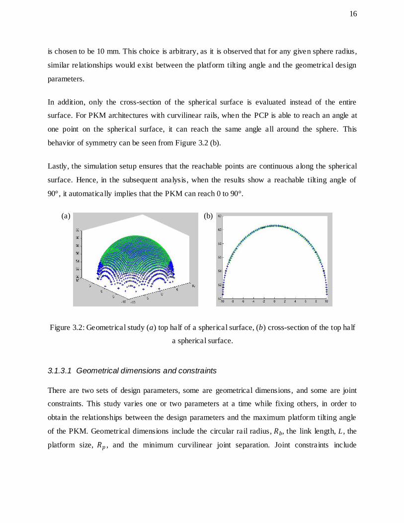
is chosen to be 10 mm. This choice is arbitrary, as it is observed that for any given sphere radius,
similar relationships would exist between the platform tilting angle and the geometrical design
parameters.
In addition, only the cross-section of the spherical surface is evaluated instead of the entire
surface. For PKM architectures with curvilinear rails, when the PCP is able to reach an angle at
one point on the spherical surface, it can reach the same angle all around the sphere. This
behavior of symmetry can be seen from Figure 3.2 (b).
Lastly, the simulation setup ensures that the reachable points are continuous along the spherical
surface. Hence, in the subsequent analysis, when the results show a reachable tilting angle of
90°, it automatically implies that the PKM can reach 0 to 90°.
Figure 3.2: Geometrical study (a) top half of a spherical surface, (b) cross-section of the top half
a spherical surface.
3.1.3.1 Geometrical dimensions and constraints
There are two sets of design parameters, some are geometrical dimensions, and some are joint
constraints. This study varies one or two parameters at a time while fixing others, in order to
obtain the relationships between the design parameters and the maximum platform tilting angle
of the PKM. Geometrical dimensions include the circular rail radius, , the link length, L , the
platform size, , and the minimum curvilinear joint separation. Joint constraints include
(a) (b)

17
curvilinear joints’ travel, , prismatic joints’ travel, , revolute joints’ travel, , and spherical
joints angle of swing, as shown previously in Figure 2.2.
The design parameters are summarized in Table 3.1 with the default values, which permit the
PKM to reach at least 90° platform tilting angle.
Table 3.1: Geometrical dimensions and constraints – default values.
Design Parameter New PKM
Circular rail radius ( ) 150 mm
Curvilinear joints’ range of travel ( ) Continuous 360°
Link length (L) 165 mm
Platform radius ( ) 20 mm
Minimum curvilinear joint separation 10°
Prismatic joints’ range of travel ( ) 065 mm
Revolute joints’ range of travel ( ) 5°70°
Spherical joints’ range of travel ±75°
3.1.3.2 Curvilinear rail radius
The radius of the curvilinear rail determines the footprint of the PKM. Figure 3.3 shows the
relationship between the platform tilting angle and the curvilinear rail radius. The platform tilting
angle achieves 90° and beyond with a curvilinear rail radius of 150 mm, and reaches maximum
at 250 mm.
Figure 3.3: Platform tilting angle vs curvilinear rail radius.
80
85
90
95
100
105
110
100 150 200 250 300 Pla
tfo
rm T
ilti
ng A
ngle
(º
)
Curvilinear Rail Radius (mm)

18
3.1.3.3 Link length
It is assumed herein, that all PKM links have the same length. The platform tilting angle of a
PKM is sensitive to link length variation. Hence, it is important to obtain their relationship. In
this study, the link lengths vary from 160 to 220 mm. It is noted that, as the length of the links
changes, the distance between the spherical workpiece and the ground requires to be adjusted
accordingly, in order to obtain maximum platform tilting angle for a given link length, as shown
in Figure 3.4.
Figure 3.4: Spherical workpiece’s height vs link length.
Figure 3.5 displays the relationship between the spherical workpiece’s height from the ground
and the link length. These results were obtained by investigating a limited number of link
lengths.

19
Figure 3.5: Height of the spherical workpiece vs link length.
Figure 3.6 shows the relationship between the platform tilting angle and the link length. It is
noted that, for the design parameters shown in Table 1, the PKM can indeed reach platform
tilting angles of 90° and beyond. The figure also indicates the existence of a possible optimal
link length; 165 mm for the PKM at hand, as defined in Table 3.1.
Figure 3.6: Platform tilting angle vs link length.
3.1.3.4 Platform size
The size of the platform can also be considered as a design parameter. The platform is generally
used to carry the spindle for a machine tool. Therefore, it would be helpful to know the possible
30
50
70
90
110
130
150
170
150 170 190 210 230
He
igh
t of
the
Sp
he
rica
l
Wo
rksp
ace
(m
m)
Link Length (mm)
60
70
80
90
100
110
150 160 170 180 190 200 210 220 230 Pla
tfo
rm T
ilti
ng A
ngle
(°
)
Link Length (mm)

20
platform sizes where the PKM can reach 90° and beyond, in order to determine the types of
spindles to be incorporated.
Figure 3.7 displays the relationship between the platform size and the tilting angle. The PKM at
hand can reach 90° tilting angle and beyond with a platform radius 25 to 35 mm. The curve
peaks at about 30 mm.
Figure 3.7: Platform tilting angle vs platform size.
3.1.3.5 Link length and platform size
The above geometrical studies show that there may be optimal dimensions for both the link
length and the platform size. For example, for the PKM at hand, the platform tilting angle
reaches a maximum value with a link length of 165 mm. Moreover, the platform size in which
the PKM reaches maximum tilt is 30 mm. Hence, the next step is to analyze the combined effect
of the two design parameters. This study may be useful for future research in workspace
optimization.
Figure 3.8 shows the platform tilting angle, with respect to the two design parameters, it is
observed that the PKM’s platform tilting angle reaches maximum when the link lengths and the
platform sizes are between 160 to 170 mm, and 25 to 35 mm, respectively.
0
20
40
60
80
100
0 10 20 30 40 50 60
Pla
tfo
rm T
ilti
ng A
ngle
(°
)
Platform Size (mm)

21
Figure 3.8: Platform tilting angle vs platform size and link length.
3.1.3.6 Minimum curvilinear joint separation
The minimum curvilinear joint separation, as shown in Figure 3.9, determines the size of the
curvilinear actuator. It is desirable to have as small curvilinear joint separation as possible, so
that the size of the curvilinear actuator can be selected with more flexibility.
Figure 3.9: Minimum curvilinear joint separation.
160
170
180
190
0 10 20 30 40 50 60 70 80 90
100
10 15 20 25 30 35 40 45 50
Link Length (mm)
Pla
tfo
rm T
iltin
g A
ngl
e (
°)
Platform Size (mm)
90-100
80-90
70-80
60-70
50-60
40-50
30-40
20-30
10-20
0-10
22
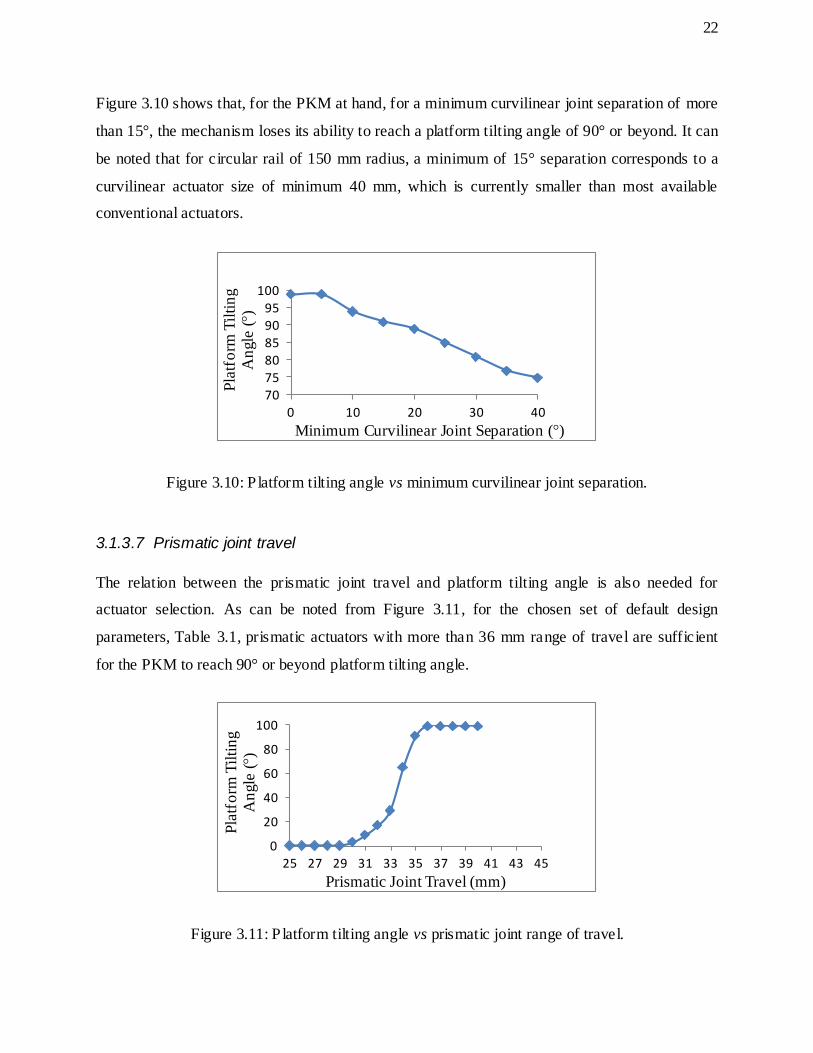
Figure 3.10 shows that, for the PKM at hand, for a minimum curvilinear joint separation of more
than 15°, the mechanism loses its ability to reach a platform tilting angle of 90° or beyond. It can
be noted that for circular rail of 150 mm radius, a minimum of 15° separation corresponds to a
curvilinear actuator size of minimum 40 mm, which is currently smaller than most available
conventional actuators.
Figure 3.10: P latform tilting angle vs minimum curvilinear joint separation.
3.1.3.7 Prismatic joint travel
The relation between the prismatic joint travel and platform tilting angle is also needed for
actuator selection. As can be noted from Figure 3.11, for the chosen set of default design
parameters, Table 3.1, prismatic actuators with more than 36 mm range of travel are sufficient
for the PKM to reach 90° or beyond platform tilting angle.
Figure 3.11: P latform tilting angle vs prismatic joint range of travel.
70
75
80
85
90
95
100
0 10 20 30 40
Pla
tfo
rm T
ilti
ng
An
gle
(°)
Minimum Curvilinear Joint Separation (°)
0
20
40
60
80
100
25 27 29 31 33 35 37 39 41 43 45
Pla
tfo
rm T
ilti
ng
An
gle
(°)
Prismatic Joint Travel (mm)

23
3.1.3.8 Spherical joint angle of swing
A spherical joint provides 3-dof mobility at a linkage connection point. However, a spherical
joint’s angle of swing is a complicating factor in the mechanical design of a PKM, especially,
when trying to achieve high platform tilting angles, Figure 3.12. Currently, commercial spherical
joints have at most ±35° angle of swing [34], [35].
Figure 3.12: Spherical joint.
From Figure 3.13, it can be noted that for the PKM at hand, a ±35° spherical joint angle of swing
provides very limited tilting angle at the platform. In order to achieve 90° or beyond platform
tilting angle, the spherical joint would need to have at least ±60° angle of swing.
Figure 3.13: P latform tilting angle vs spherical joint angle of swing.
0
20
40
60
80
100
0 20 40 60 80 100
Pla
tfo
rm T
ilti
ng A
ngle
(°)
Spherical Joint Angle of Swing (°)

24
3.1.3.9 Summary
The maximum platform tilting angle of a PKM was investigated with respect to different design
parameters, for a spherical workpiece of 10 mm radius. It is shown that the tilting angle is
sensitive to changes in link length and platform size. Furthermore, there exists optimal solutions
for the two design parameters, and this finding can be used for workspace optimization.
The default design parameters given in Table 3.1 can be adjusted to yield larger platform tilting
angle. Moreover, setting the prismatic joints’ range of travel to 0 to 40 mm would be sufficient
for obtaining a minimum of 90° platform tilting angle, for a spherical workspace with a radius of
less than 12 mm. The modified PKM parameter values are shown in Table 3.2.
Table 3.2: Geometrical dimensions and constraints.
Design Parameter New PKM
Circular rail radius ( ) 150 mm
Curvilinear joints’ range of travel ( ) Continuous 360°
Link length (L) 165 mm
Platform radius ( ) 25 mm
Minimum curvilinear joint separation 5°
Prismatic joint’s range of travel ( ) 040 mm
Revolute joints’ range of travel ( ) 5°70°
Spherical joints’ range of travel ±75°
3.1.4 Singularities
Kinematic singularity occurs when a mechanism loses one or more dof for certain configurations,
and it is related to the system inverse kinematic Jacobian matrix, , which was derived in
Chapter 2. For PKMs, kinematic singularities are typically classified into three categories [36]:
Type I singularity, also known as serial singularity, results when the determinant of goes to
infinity, namely,
(3.3)

25
Type I singularity indicates that there exist some nonzero vectors that result in zero vectors.
Physically, it means that the mobile platform remains stationary, while the actuators are moving.
Type I singularities usually occur at the boundary of the workspace, where different branches of
the inverse kinematic solutions converge.
Type II singularity, also known as parallel singularity, results when the determinant of is
equal to zero, namely,
(3.4)
Type II singularity indicates that there exist some nonzero vectors that result in zero
vectors. Namely, the mobile platform is able to achieve motion in space, while all the actuators
are completely locked.
Type III singularity occurs when both Type I and Type II singularities are present at the same
time.
It is to be noted, that the inverse kinematic Jacobian matrix derived in Section 2.2.3 is not
homogenous in terms of units for two reasons: (i) the PKM has two types of actuated joints, and
their joint-space coordinates have different units (e.g., millimetre for prismatic joints, and degree
for curvilinear joints), and (ii) the mobile platform has translational and rotational dof. Therefore,
the “closeness” of a 6-dof PKM configuration to a singularity can be only determined with
respect to the distribution of Jacobian determinant over the workspace. For example, a Type II
singularity occurs at a configuration when the determinant of the inverse kinematic Jacobian
matrix is low compared to the determinants for other configurations.
Similar to workspace and platform tilting angle analyses, s ingularity simulations were carried out
through a discretization method. The determinant of the inverse kinematic Jacobian matrix is
checked at each point on the spherical surface, which has a radius of 10 mm. If the determinant
value at a particular point is relatively high or low compared to its surrounding, the point is close
to being singular.

26
Herein, the relative high and low determinant values are chosen to be 4 and 0.25, respectively.
This choice of selection is based on observations from the previously built prototypes, and
existing analyses [18], [37]. The numbers do approximate the regions of singularities within the
workspace of the PKM, as shown in Figure 3.14, blue points indicate singular positions.
Figure 3.14: Singular positions within the workspace (a) perspective view, (b) top view.
3.2 Dynamic Stiffness
The position accuracy of a PKM is directly related to its stiffness. In particular, the dynamic
stiffness indicates the magnitude of the vibration response of the mechanism with respect to a
time-varying load. The stiffness of a PKM is highly related to its specific configuration [14].
Hence, it is important to study the configuration-dependency of stiffness, as the result can be
used to plan tool trajectory to avoid regions/directions of excessive structural vibration, and also
to be used in the design of closed-loop controllers for vibration damping [38].
In this study, the minimum dynamic stiffness of the PKM developed in this Thesis was
evaluated, as it relates to the maximum deformation at the PCP. The minimum dynamic stiffness
occurs when the frequency of the applied force is equal to one of the natural frequencies of the
PKM .
Type I Singularity
Type II Singularity (a) (b)

27
3.2.1 Configuration Dependency of Dynamic Stiffness
At a given frequency, the dynamic stiffness of a PKM can be calculated by inverting the
Frequency Response Function (FRF). The Cartesian FRFs of the PKM are obtained using a
commercial FEA software package, ANSYS. To study the configuration-dependency of dynamic
stiffness, harmonic analysis was conducted for five different PKM configurations. Each
configuration corresponds to a set of joints locations, where represents the separation
between the curvilinear joints, and represents the travel of the prismatic joints ( ). As
can be noted in Figure 3.15, the five configurations are defined by: (i) ,
(ii) , (iii) , (iv) , and
(v) . For Configuration 5, the angles between the curvilinear joints are
, and , respectively.
Configuration 1 can be considered as the Reference Configuration, where its prismatic-joints are
at the middle of their travel range, and the curvilinear joints are equally spaced. Configurations 2
to 5 represent the relative extreme locations of the joints. By studying the five chosen PKM
configurations, an approximate relationship between PKM configuration and its dynamic
stiffness can be obtained. The geometrical dimensions used for this analysis were listed in Table
3.2.

28
Figure 3.15: PKM configurations for stiffness analysis (a) Configuration 1, (b) Configuration 2,
(c) Configuration 3, (d) Configuration 4, and (e) Configuration 5.
For each harmonic analysis, a sinusoidal force of 1 N magnitude is applied to the PCP along the
x, y and z-axes. For every solution, the Cartesian displacement of the PCP is captured along the
direction of the applied force. The contacts between the pin and housing of revolute and
(a) (b)
(c) (d)
(e)

29
spherical joints are modeled as non-separation, and all other contacts are bonded [39]. The
constant damping ratio for the PKM is set as 1%. Although the estimated damping ratio might
not be a close approximation, it is nonetheless adequate for this analysis, as the absolute
magnitude of stiffness values are irrelevant for comparison between different PKM
configurations. Figure 3.16 shows an example of the simulation environment.
Figure 3.16: FEA simulation environment.
The Cartesian components of the FRFs for each PKM configuration are shown in Figure 3.17. It
can be observed that the FRFs are indeed highly dependent on PKM configurations.
The minimum dynamic stiffness values along the three Cartesian axes for the five PKM
configurations are summarized in Table 3.3. For ease of comparison, all stiffness values are
presented as a ratio with respect to Configuration 1, which is the reference configuration. The
stiffness of Configuration 1 is normalized to 1.

30
Figure 3.17: FRF for different PKM configurations along (a) xx, (b) yy, and (c) zz directions,
respectively.
0.E+00
1.E-05
2.E-05
3.E-05
4.E-05
5.E-05
0 100 200 300 400 500 600
FRFx
x (m
/N)
Frequency (Hz)
Configuration 1
Configuration 2
Configuration 3
Configuration 4
Configuration 5
0.E+00
2.E-05
4.E-05
6.E-05
8.E-05
1.E-04
1.E-04
0 100 200 300 400 500 600
FRFy
y (m
/N)
Frequency (Hz)
Configuration 1
Configuration 2
Configuration 3
Configuration 4
Configuration 5
0.E+00
1.E-05
2.E-05
3.E-05
4.E-05
0 100 200 300 400 500 600
FRFz
z (m
/N)
Frequency (Hz)
Configuration 1
Configuration 2
Configuration 3
Configuration 4
Configuration 5
(a)
(c)
(b)
31
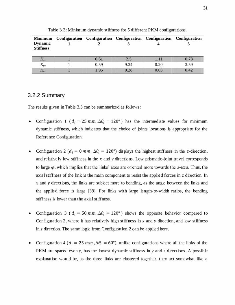
Table 3.3: Minimum dynamic stiffness for 5 different PKM configurations.
Minimum
Dynamic
Stiffness
Configuration
1
Configuration
2
Configuration
3
Configuration
4
Configuration
5
Kxx 1 0.61 2.5 1.11 0.78
Kyy 1 0.59 9.34 0.20 3.59
Kzz 1 1.95 0.28 0.03 0.42
3.2.2 Summary
The results given in Table 3.3 can be summarized as follows:
Configuration 1 ( ) has the intermediate values for minimum
dynamic stiffness, which indicates that the choice of joints locations is appropriate for the
Reference Configuration.
Configuration 2 ( ) displays the highest stiffness in the z-direction,
and relatively low stiffness in the x and y directions. Low prismatic-joint travel corresponds
to large , which implies that the links’ axes are oriented more towards the z-axis. Thus, the
axial stiffness of the link is the main component to resist the applied forces in z direction. In
x and y directions, the links are subject more to bending, as the angle between the links and
the applied force is large [39]. For links with large length-to-width ratios, the bending
stiffness is lower than the axial stiffness.
Configuration 3 ( ) shows the opposite behavior compared to
Configuration 2, where it has relatively high stiffness in x and y direction, and low stiffness
in z direction. The same logic from Configuration 2 can be applied here.
Configuration 4 ( ), unlike configurations where all the links of the
PKM are spaced evenly, has the lowest dynamic st iffness in y and z directions. A possible
explanation would be, as the three links are clustered together, they act somewhat like a

32
single cantilever beam, in which the PKM no longer retains its closed kinematic loop
structure, and consequently loses the ability to resist force in all directions.
Configuration 5 ( ) shows the largest discrepancy in stiffness
between the x and y directions. Using the abovementioned argument from above, when two
links are close to each other, they act more like a single link. While the third link is
positioned far apart, the configuration translates into a two-link mechanism. In this
configuration, the force applied along the y-axis has a large fraction of its components acting
axially to the links, which results in high axial stiffness. The force applied in the x direction,
on the other hand, is normal to the link axis which creates bending motion, which leads to
low stiffness.
To conclude, the dynamic stiffness of the PKM is highly dependent on its configuration. In
general, curvilinear joints should be evenly spaced on the circular rail in order for the PKM to
acquire high overall PKM stiffness. Furthermore, the stiffness of the new PKM is sensitive to the
change in , which corresponds to prismatic-joint travel. Thus, for applications which require
high stiffness in the x and y directions, it is desirable to operate in a large prismatic-joint travel
range. Similarly, for applications which require high stiffness in the z direction, it is favorable to
operate in a low prismatic joint travel range.
3.3 Comparative Analysis
In this Section, the proposed new PKM is compared with three reference PKMs shown in Figure
3.18. All the compared PKMs are based on three-chain topology, and each contains two actuated
joints, labeled as and . is a curvilinear joint which moves along the circular rail. The
primary difference between the new PKM and the Reference PKMs lies in the motion of the .
In the new PKM, it moves in radial direction with respect to the rail.

33
Figure 3.18: Compared PKMs (a) the new PKM, (b) the Eclipse, (c) the Alizade PKM, and, (d)
the Glozman PKM.
The geometrical parameters and kinematic constraints of the compared PKMs, namely, the new
PKM, the Eclipse, the Alizade PKM and the Glozman PKM are summarized in Table 3.4. The
design parameter values were chosen according to the following criteria: (i) the PKM can
achieve at least 90° platform tilting angle, and (ii) the dimensions are identical for all the PKMs.
For the Glozman PKM, the total length of its two links is 240 mm instead of 165 mm. This extra
length is required as it is the closest to the dimension of the other PKMs’ links, to achieve the 90°
platform tilting angle. It is assumed that a small difference in link length has limited effect on the
dynamic stiffness of the PKMs.
(a) (b)
(c) (d)

34
Table 3.4: Geometrical parameters and kinematic constraints of the PKMs.
Design Parameter New PKM Eclipse
PKM
Alizade
PKM
Glozman
PKM
Base radius ( ) 150 mm 150 mm 150 mm 150 mm
Platform radius ( ) 25 mm 25 mm 25 mm 25 mm
Link length (L) 165 mm 165 mm 165 mm1 120 mm
Curvilinear base joints’ range of travel
( )
Continuous
360° Continuous
360° Continuous
360° Continuous
360°
Prismatic joints’ range of travel ( ) 65 mm 65 mm 65 mm -
Revolute joints’ range of travel ( ) 5°70° 5°70° 5°70° 5°70°
Spherical joints’ range of travel ±70° ±70° ±70° ±70°
3.3.1 Platform Tilting Angle
To justify the above selection of design parameters, the maximum platform tilting angle is
calculated for each of the compared PKMs using the same method in Section 3.1.2. The results
are given in Figure 3.19, which shows that the maximum platform tilting angle for all the PKMs
do exceed 90° for a sphere radius of 1 to 5 mm. One thing to be noted is that the design
parameters are not optimized, so it only shows the PKMs’ ability to reach 90° platform angle,
but suggests nothing about their comparative workspace size.
Figure 3.19: Maximum platform tilting angle for the compared PKMs.
1 The link length of the Alizade PKM is defined at the middle of the prismatic- joint travel range
85
90
95
100
0 1 2 3 4 5 6 Pla
tfo
rm T
iltin
g A
ngl
e
(°)
Sphere Radius (mm)
the New PKM
the Eclipse PKM
the Alizade PKM
the Glozman PKM

35
3.3.2 Stiffness
The dynamic analysis of the new PKM presented in Section 3.2.1 is repeated here for all four
PKMs with the dimensions specified in Table 3.4, and the results are used for comparison. Three
different PKM configurations are employed in this study.
The first configuration is chosen where the joints for each PKM have minimum travel, as
shown in Figure 3.20. In the new PKM, the Eclipse PKM and the Alizade PKM, their prismatic-
joints travel 0 mm for this configuration. In the Glozman PKM, its joints are revolute, and
the joints’ travels are represented by the angle . In order to avoid mechanical interference, the
minimum travel for the Glozman PKM is set to be 30°.
Figure 3.20: Configuration 1 (a) the new PKM, (b) the Eclipse, (c) the Alizade PKM, and, (d) the
Glozman PKM.
(a) (b)
(c) (d)

36
The second configuration is chosen where the joints for each of the PKMs are at the middle
of its maximum range of travel, which is shown in Figure 3.17. In the new PKM, the Eclipse and
the Alizade PKM, the prismatic joints travel is 32.5 mm, while in the Glozman PKM, the
revolute joints are at 60° travel.
The third configuration is selected where the joints for each of the PKMs reach maximum
travel, as shown in Figure 3.21. The prismatic joints travel 65 mm for the new PKM, the Eclipse
and the Alizade PKM. For Glozman PKM, the revolute joints travel is set to be 90°.
Figure 3.21: Configuration 3 (a) the new PKM, (b) the Eclipse, (c) the Alizade PKM, and, (d) the
Glozman PKM.
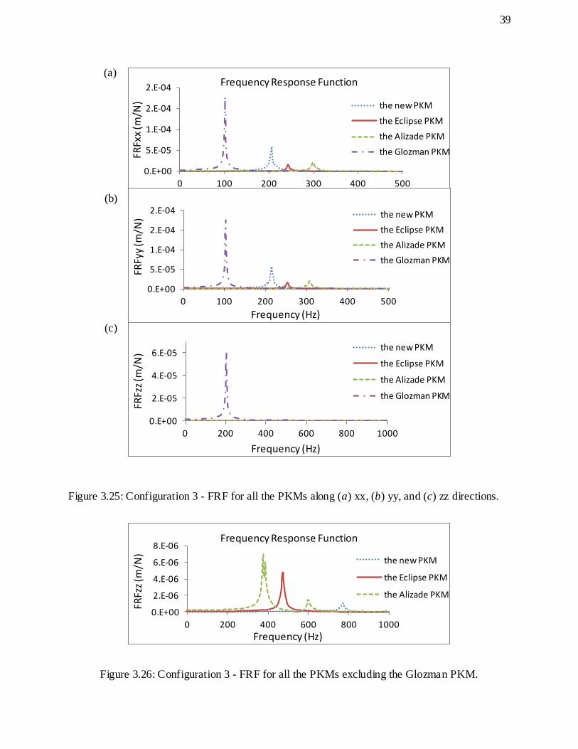
FRFs for Configurations 1 through 3 are presented in Figure 3.22, Figure 3.24, and Figure 3.25,
respectively. The FRFs’ magnitudes for the Glozman PKM are large compared to the other three
PKMs in the z direction for Configurations 1 and 2. Hence, two separate graphs displaying the
FRFs of the new, the Eclipse and the Alizade PKM in the z direction can be seen in Figure 3.23
and Figure 3.26.
(a) (b)
(c) (d)

37
Figure 3.22: Configuration 1 - FRF for all the PKMs along (a) xx, (b) yy, and (c) zz directions.
Figure 3.23: Configuration 1 - FRF for all the PKMs excluding the Glozman PKM.
0.E+00
5.E-05
1.E-04
2.E-04
2.E-04
0 100 200 300 400 500
FRFx
x (m
/N)
Frequency (Hz)
Frequency Response Function
the new PKM
the Eclipse PKM
the Alizade PKM
the Glozman PKM
0.E+00
5.E-05
1.E-04
2.E-04
2.E-04
0 100 200 300 400 500
FRFy
y (m
/N)
Frequency (Hz)
the new PKM
the Eclipse PKM
the Alizade PKM
the Glozman PKM
0.E+00
2.E-05
4.E-05
6.E-05
8.E-05
0 100 200 300 400 500
FRFz
z (m
/N)
Frequency (Hz)
the new PKM
the Eclipse PKM
the Alizade PKM
the Glozman PKM
0.E+00
2.E-07
4.E-07
6.E-07
8.E-07
0 200 400 600 800 1000
FRFz
z (m
/N)
Frequency (Hz)
Frequency Response Function
the new PKM
the Eclipse PKM
the Alizade PKM
(a)
(b)
(c)

38
Figure 3.24: Configuration 2 - FRF for all the PKMs along (a) xx, (b) yy, and (c) zz directions.
0.E+00
1.E-05
2.E-05
3.E-05
4.E-05
5.E-05
0 100 200 300 400 500
FRFx
x (m
/N)
Frequency (Hz)
Frequency Response Function
the new PKM
the Eclipse PKM
the Alizade PKM
the Glozman PKM
0.E+00
1.E-05
2.E-05
3.E-05
4.E-05
5.E-05
0 100 200 300 400 500
FRFy
y (m
/N)
Frequency (Hz)
the new PKM
the Eclipse PKM
the Alizade PKM
the Glozman PKM
0.E+00 1.E-06 2.E-06 3.E-06 4.E-06 5.E-06 6.E-06
0 400 800 1200 1600 2000
FRFz
z (m
/N)
Frequency (Hz)
the new PKM
the Eclipse PKM
the Alizade PKM
the Glozman PKM
(a)
(b)
(c)
39
Figure 3.25: Configuration 3 - FRF for all the PKMs along (a) xx, (b) yy, and (c) zz directions.
Figure 3.26: Configuration 3 - FRF for all the PKMs excluding the Glozman PKM.
0.E+00
5.E-05
1.E-04
2.E-04
2.E-04
0 100 200 300 400 500
FRFx
x (m
/N)
Frequency (Hz)
Frequency Response Function
the new PKM
the Eclipse PKM
the Alizade PKM
the Glozman PKM
0.E+00
5.E-05
1.E-04
2.E-04
2.E-04
0 100 200 300 400 500
FRFy
y (m
/N)
Frequency (Hz)
the new PKM
the Eclipse PKM
the Alizade PKM
the Glozman PKM
0.E+00
2.E-05
4.E-05
6.E-05
0 200 400 600 800 1000
FRFz
z (m
/N)
Frequency (Hz)
the new PKM
the Eclipse PKM
the Alizade PKM
the Glozman PKM
0.E+00
2.E-06
4.E-06
6.E-06
8.E-06
0 200 400 600 800 1000
FRFz
z (m
/N)
Frequency (Hz)
Frequency Response Function
the new PKM
the Eclipse PKM
the Alizade PKM
(a)
(b)
(c)

40
3.3.3 Summary
Table 3.5 to 3.7 summarize the minimum dynamic stiffness values along the three Cartesian axes
for the compared PKMs.
Table 3.5: PKMs’ stiffnesses for Configuration 1.
Minimum
Dynamic
Stiffness
The New
PKM
(N/µm)
The Eclipse
PKM
(N/µm/)
The Alizade
PKM
(N/µm)
The Glozman
PKM
(N/µm)
Kxx 0.017 0.064 0.08 0.0096
Kyy 0.018 0.068 0.051 0.0099
Kzz 9.26 26.67 2.04 0.040
Table 3.6: PKMs’ stiffnesses for Configuration 2. Minimum
Dynamic
Stiffness
The New
PKM
(N/µm)
The Eclipse
PKM
(N/µm)
The Alizade
PKM
(N/µm)
The Glozman
PKM
(N/µm)
Kxx 0.052 0.050 0.028 0.034
Kyy 0.061 0.047 0.027 0.040
Kzz 1.88 0.58 0.19 4.02
Table 3.7: PKMs’ stiffnesses for Configuration 3. Minimum
Dynamic
Stiffness
The New
PKM
(N/µm)
The Eclipse
PKM
(N/µm)
The Alizade
PKM
(N/µm)
The Glozman
PKM
(N/µm)
Kxx 0.078 0.039 0.016 0.0056
Kyy 0.067 0.037 0.016 0.0057
Kzz 2.15 0.21 0.15 0.017

41
The configuration-dependency of the new PKM was studied in Section 3.2.1, and the same
reasoning applies to this comparative study. The PKM’ stiffness values are highly dependent on
its revolute joints’ travel, , and is inversely related to prismatic joints’ travel. Thus, the PKM
is least stiff in the x and y directions, and stiffest in the z direction for Configuration 1. For
Configurations 2 and 3, the PKM’s stiffness in the x and y directions increases, and the stiffness
in the z direction drops.
For the Eclipse, the angle remains constant, as its joints all move vertically together.
Therefore, the most important factor which affects this PKM’s stiffness is the locations of on
the vertical columns. Each vertical column can be regarded as a cantilever beam, hence, when
is positioned at its higher end, the column is subjected to bending, which leads to a decrease
in stiffness. However, at the lower end of the column, there is little bending from the cantilever
beam effect. Thus, the Eclipse has relatively high stiffness compared to other mechanisms at
Configuration 1. In general, the Eclipse has higher stiffness than the new PKM with low
travel, and lower stiffness with high travel.
Alizade PKM is less stiff than the new PKM, except in the x and y directions for Configuration 1,
which is the least stiff configuration for the new PKM. There are two main factors which affect
the dynamic stiffness of the Alizade PKM. The first one is its extens ible link stiffness, which is
related to the link length and the prismatic joint stiffness. The other factor is the revolute joints’
travel . In the study, it can be seen that the link stiffness is the dominating factor. For example,
when the angle is large for high travel, and if is the dominating factor, the stiffness in z
direction should improve as travel increases. However, the study shows the opposite, which
indicates that the increasing link length outweighs the effect of increasing in .
The stiffness of the new PKM is also higher than that of the Glozman PKM, except in the z
direction for Configuration 2. The main problem with the Glozman PKM is that, its first links act
as cantilever beams, which affect the stiffness along all axes, depending on the orientation of
these links. However, in Configuration 2, the second links are almost collinear with the first
links, which reduce the cantilever beam effect of the first links, resulting in a high stiffness
configuration for the Glozman PKM.

42
To summarize, the new PKM does exhibit higher dynamic stiffness than all the Reference PKMs
do for Configurations 2 and 3. The only exception is the Glozman PKM, which is stiffer in the z
direction for Configuration 2. Furthermore, the least x, y direction stiffnesses of the new PKM
occurs in Configuration 1, and the case is the opposite for the Eclipse and Alizade PKM. Hence,
the new PKM displays comparatively lower stiffness in Configuration 1. Lastly, the new PKM
displays the highest stiffness value in the x and y directions, while the Eclipse has the highest
stiffness value in the z direction.

43
Chapter 4 Prototype
In the design of machine tools, it is not sufficient to only study the mechanisms employed, as
there are more issues which need to be addressed. For instance, mechanism study in Chapter 3
did not consider the weight of the kinematic chains, which is a crucial factor in the design of
meso-Milling Machine Tools (mMT). Moreover, interference is more prominent for the actual
machine design, due to links having some thickness. Lastly, cost is another issue to be
considered, and plays a major role in decision making. Therefore, prototyping is required to
better understand the design issues as a whole.
As discussed in Chapter 3, PKMs exhibit several drawbacks for machine design, including
singularities and high configuration-dependency of dynamic stiffness. Hence, in this Thesis, a
redundant reconfigurability approach was chosen for the development of the PKM based mMT.
Namely, kinematic redundancies were introduced by adding more degrees-of-freedom (dof) than
those required by the tasks at hand, and reconfigurability was achieved through
locking/unlocking of the redundant dof. This approach allows the use of redundancy to address
the drawbacks of PKM-based machine tools, e.g., eliminating singularities [38], [40].
Three 9-dof redundant Reconfigurable meso-Milling Machine Tool (RmMT) prototypes were
designed and built within the framework of this Thesis. The first and the second designs are
based on downsizing an earlier design, namely, the Eclipse [17], and the third prototype is based
on a new PKM architecture. All three RmMT designs are based on PKMs with a 3×PPPRS
topology.
In this Chapter, the mechanical designs of the prototypes are described in detail, namely,
presenting the architectures and the choice of selection for mechanical components. Moreover,
the advantages and disadvantages for each prototype are discussed.

44
4.1 Prototype I
The mechanical design for Prototype I, shown in Figure 4.1, is based on the Eclipse mechanism.
The Eclipse is in a family of PKMs with curvilinear base joints, and can achieve 90° tilting angle
for a considerable large workspace [17]. It was investigated in detail and compared with several
alternatives, including the Hexapod, and PKMs with a triangular base, by Mr. Hay Azulay [41].
The conclusion was that the Eclipse mechanism has comparatively a large achievable workspace
and compact size, which makes it suitable for mMT design.
Figure 4.1: CAD model of Prototype I.
The 9-dof Prototype I consists of three chains and a circular base plate. Each chain contains a
slider, which moves on the curvilinear guide. A linear actuator is mounted on the slider, and
moves in tangential direction with respect to the curvilinear guide, and is referred to herein as the
tangential actuator. On top of that, another vertically moving linear actuator is connected to the
tangential actuator through an adaptor, and is referred to herein as the vertical actuator. Each

45
chain also includes an inextensible link which connects the vertical actuator to the mobile
platform through revolute and spherical joints, respectively.
4.1.1 Mechanical Design
4.1.1.1 Base
The base, as shown in Figure 4.2, was machined from a single block of steel, in order to ensure
its accuracy. The primary function of the base is to provide a platform to install the curvilinear
guides. It is noted that, on top the base surface, a shoulder was machined with high accuracy, in
order to provide accurate positioning for mounting the curvilinear guide. Moreover, the structure
was designed to be heavy for vibration damping. The size of the base is 150 mm in radius and
137 mm in height. Lastly, there are considerable amount of empty space inside the base, as well
as having windows on the side wall. These features were designed for easy and quick access to
the workspace of the machine.
Figure 4.2: Base design of Prototype I.
4.1.1.2 Links
The link length is an important design parameter, as it is related to the platform tilting angle.
However, a complete tilting angle analysis was not conducted for the prototype design, and a

46
simpler way of measuring tiling angle was achieved using CAD. The procedure can be found in
Appendix A.
In this design, the length of the link was chosen to be 223 mm, and a maximum platform tilting
angle of 43° could be achieved. It is noted that the spherical joint’s angle of swing imposed
major limitation in platform rotation, and with conventional spherical joints of around ±30° angle
of swing, the prototype is not able to reach 90° platform tilting.
The links were designed to be hollow tubes with a circular cross-section, which had an outer
diameter of 19 mm and an inner diameter of 14.2 mm, as shown in Figure 4.3. The choice of this
specific geometry was made for two reasons, (i) weight restrictions, and (ii) machine stiffness
[39]. Hence, the hollow tube design was a compromise between reducing the weight and
maintaining the stiffness of the links.
Figure 4.3: Link design of Prototype I.
4.1.1.3 Mobile Platform
Using the procedure shown in Appendix A, it was determined that for Prototype I, the platform
tilting angle is inversely proportional to the size of the mobile platform. Hence, in this design, a
small mobile platform of 45 mm radius was employed, as shown in Figure 4.4. This choice of
dimension provides high platform tilting angle, while avoiding any interference between the
mechanical components.

47
Figure 4.4: Mobile platform design of Prototype I.
4.1.1.4 Adaptor
The primary function of the adaptors is to connect the two linear actuators. Similar to the design
for links, the two major design considerations were stiffness and weight, and there was a tradeoff
between the two. In the design for stiffness, bulky and heavy structures are preferred, and the
adaptors should be made thick. However, there is a weight restriction, and the adaptors are
required to be designed as light as possible. Moreover, the height of the adaptors is required to be
at least the length of the vertical actuator plus half of its range of travel, in order for the actuators
to move in full range. With the above design constraints in mind, the eventual dimensions of the
adaptor were 75×75×150 mm, with a thickness of 5 mm, as shown in Figure 4.5.
Figure 4.5: Adaptor design of Prototype I.
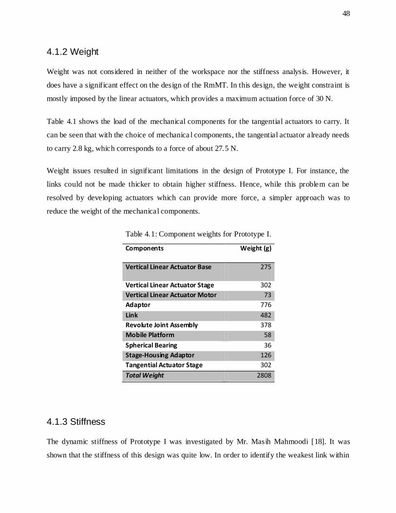
48
4.1.2 Weight
Weight was not considered in neither of the workspace nor the stiffness analysis. However, it
does have a significant effect on the design of the RmMT. In this design, the weight constraint is
mostly imposed by the linear actuators, which provides a maximum actuation force of 30 N.
Table 4.1 shows the load of the mechanical components for the tangential actuators to carry. It
can be seen that with the choice of mechanica l components, the tangential actuator already needs
to carry 2.8 kg, which corresponds to a force of about 27.5 N.
Weight issues resulted in significant limitations in the design of Prototype I. For instance, the
links could not be made thicker to obtain higher stiffness. Hence, while this problem can be
resolved by developing actuators which can provide more force, a simpler approach was to
reduce the weight of the mechanical components.
Table 4.1: Component weights for Prototype I.
Components Weight (g)
Vertical Linear Actuator Base 275
Vertical Linear Actuator Stage 302
Vertical Linear Actuator Motor 73
Adaptor 776
Link 482
Revolute Joint Assembly 378
Mobile Platform 58
Spherical Bearing 36
Stage-Housing Adaptor 126
Tangential Actuator Stage 302
Total Weight 2808
4.1.3 Stiffness
The dynamic stiffness of Prototype I was investigated by Mr. Masih Mahmoodi [18]. It was
shown that the stiffness of this design was quite low. In order to identify the weakest link within

49
the structure, the amplitudes at different points on the machine were captured. It was noted that
at around 160 Hz, the FRF at the revolute joints, which is mounted at the top of the adaptors,
contributes approximately 64% of the overall deformation at the Platform Center Point (PCP). It
is noted that the adaptors act like cantilever beams. Hence, the cantilever beam effect of the
adaptors needed to be addressed. One solution was to make them bulky. However, this would
lead to more weight. Another alternative was to reduce the height of the adaptors, which formed
the basis for the design of Prototype II.
4.1.4 Prototype Built
The built prototype is shown in Figure 4.6. It can be noted that actuating all three kinematic
chains was not a requirement for this Thesis. Thus, in all the built prototypes, only one chain was
actuated, while the others were kept passive for cost saving. Moreover, each kinematic chain was
attached on a segment of the full curvilinear guide, and consequently, full curvilinear range of
travel could not be achieved.
The passive chains could be adjusted manually to simulate the motion of the actuated chain. The
prototype did not demonstrate the full capability of the RmMT, but it did provide a test bed to
investigate interactions between mechanical links, to evaluate actuator performance, and to
obtain valuable experience for machine design, specifically, the design for tolerance and
assembly. Engineering drawings for Prototype I can be found in Appendix B.

50
Figure 4.6: The built Prototype I.
4.2 Prototype II
RmMT Prototype II, shown in Figure 4.7, was also designed based on the Eclipse mechanism.
The main difference between the prototypes is the arrangement of the actuators’ positions. In
Prototype II, for each kinematic chain, the adaptor is connected directly to the slider. Then, the
tangential actuator is mounted on the adaptor, and the vertical actuator is attached to the
tangential actuator. The focus for the design was to reduce the height of the adaptor, in order to
obtain higher stiffness and less weight.

51
Figure 4.7: CAD design of Prototype II.
4.2.1 Mechanical Design
4.2.1.1 Base
Prototype II employed the same base as Prototype I, mostly to save design and fabrication costs.
It can be noted that with this arrangement of the actuators, due to the vertical actuator occupying
large amount of space within the base, the workspace of this prototype is severely limited, as
interferences between the links are more noticeable.
4.2.1.2 Links
In Prototype II, the links were designed as hollow tubes with the same circular cross-section as
Prototype I, as shown in Figure 4.8. However, due to interference and limited operating space,
the link length was reduced in order to obtain comparable platform tilting angle as Prototype I.
The link length for the design was 128 mm, and the mobile platform was able to achieve 40° of
tilting.

52
Figure 4.8: Link design of Prototype II.
4.2.1.3 Mobile Platform
The size of the mobile platform chosen for Prototype II was 45 mm. Although a smaller mobile
platform was preferred for Prototype II, due to limited space, the size of the mobile platform was
nonetheless kept the same as Prototype I, in order to avoid any interference between the links.
4.2.1.4 Adaptors
Due to adjusted actuators’ arrangement in Prototype II, the vertical actuator range of travel did
not need to be taken into account in the design of the adaptors. Thus, it allowed for a shorter
adaptor height. The height of the adaptor in Prototype II was 83 mm, which is a 45% decrease
from Prototype I, as shown in Figure 4.9. With the same thickness, a shorter adaptor results in a
reduction of both its cantilever effect and its weight.
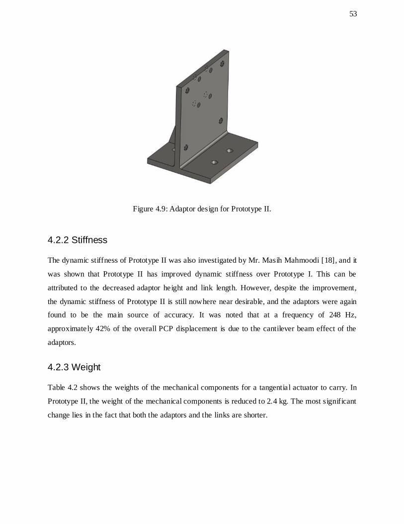
53
Figure 4.9: Adaptor design for Prototype II.
4.2.2 Stiffness
The dynamic stiffness of Prototype II was also investigated by Mr. Masih Mahmoodi [18], and it
was shown that Prototype II has improved dynamic stiffness over Prototype I. This can be
attributed to the decreased adaptor height and link length. However, despite the improvement,
the dynamic stiffness of Prototype II is still nowhere near desirable, and the adaptors were again
found to be the main source of accuracy. It was noted that at a frequency of 248 Hz,
approximately 42% of the overall PCP displacement is due to the cantilever beam effect of the
adaptors.
4.2.3 Weight
Table 4.2 shows the weights of the mechanical components for a tangential actuator to carry. In
Prototype II, the weight of the mechanical components is reduced to 2.4 kg. The most significant
change lies in the fact that both the adaptors and the links are shorter.

54
Table 4.2: Component weights for Prototype II.
Components Weight (g)
Vertical Linear Actuator Base 275
Vertical Linear Actuator Stage 302
Vertical Linear Actuator Motor 73
Adaptor 472
Link 198
Revolute Joint Assembly 351
Mobile Platform 58
Spherical Bearing 36
Stage-Housing Adaptor 337
Tangential Actuator Stage 302
Total Weight 2404
4.2.4 Prototype Built
The built Prototype II is shown in Figure 4.10. Similar to Prototype I, the passive chains can be
adjusted manually to simulate motion of the actuated chains. Prototype II was used primarily to
conduct experiments on configuration-dependency of stiffness [38]. Engineering drawings of
Prototype II can be found in Appendix C.

55
Figure 4.10: The built Prototype II.
4.3 Prototype III
Different alternatives were considered to compensate the cantilever beam effect from the
adaptors, and none of them resulted in significant improvement. Thus, the design approach had
to shift from downsizing existing designs to developing an RmMT based on a new PKM
architecture, namely, by arranging the actuators in a different way, the adaptors were completely
eliminated from the design. The mechanical design of Prototype III is shown in Figure 4.11.
The 9-dof RmMT consists of three identical kinematic chains, where each chain is attached to a
slider that moves along a curvilinear guide rail. The slider can be moved to a desired location and,
then, locked. Two linear actuators are placed on top of the slider. The first linear actuator moves
tangentially with respect to the curvilinear guide, and the second linear actuator, which is
mounted on top of the first one, moves in a radial direction, and is referred herein as the radial
actuator. A revolute joint connects the linear actuator to a fixed length link, and the link is
subsequently connected to the mobile platform though a spherical joint.

56
Figure 4.11: CAD design of Prototype III.
To demonstrate redundancy, Figure 4.12 shows how the RmMT can be reconfigured by locking
the sliders on the curvilinear guide at different positions. For instance, this particular
configuration of the RmMT allows the platform to obtain higher tilting angle than when the three
sliders are spaced evenly apart.

57
Figure 4.12: RmMT prototype with its sliders locked on the curvilinear guide.
4.3.1 Mechanical Design
4.3.1.1 Base
The structure of Prototype III is inverted compared to the pervious prototypes. Thus, the mobile
platform is positioned above the base. Hence, the base of the prototype was designed as a simple
circular plate, with a radius of 150 mm, as shown in Figure 4.13. It has several advantages over
the base design for Prototypes I and II. For instance, it is easier to machine, requires less material
and time to fabricate, and it is stiffer due to its bulky structure.

58
Figure 4.13: Base design of Prototype III.
4.3.1.2 Links
The links were designed as hollow tubes with the same cross-section as for Prototypes I and II,
as shown in Figure 4.14. Based on CAD-based measurements, the length of the link for
Prototype III was designed to be 168 mm, which is its optimal value for achieving best tilting
angle. It is noted that the link length chosen here is similar to the simulation results obtained in
Chapter 3. This is an interesting observation, and it may suggest that the 6-dof mechanism based
simulations can be used to investigate geometrical design of the 9-dof RmMT.
Figure 4.14: Link design of Prototype III.
4.3.1.3 Mobile Platform
The mobile platform was redesigned for Prototype III, in order to house a commercial spindle.

59
The platform is shown in Figure 4.15. A hole with a 10 mm radius was machined at the center of
the mobile platform, and the tolerance was designed to be sliding fit with respect to the spindle.
In order to lock the spindle in place, a simple locking mechanism was implemented, where a side
screw was inserted into the clamp, in order to tighten the spindle onto the platform. The mobile
platform had a radius of 20 mm.
Figure 4.15: P latform design of Prototype III.
4.3.2 Stiffness
From Mr. Masih Mahmoodi’s analysis, Prototype III displayed better stiffness than Prototype I
and II, which coincides with the simulation results obtained from mechanism studies. This
improvement of the stiffness is due to the removal of the adaptors from the design, which
eliminates the cantilever beam effect.
4.3.3 Weight
It is seen from Table 4.3, that the weight of Prototype III is the lowest compared to the previous
prototypes. This is expected, as the third prototype did not have the adaptor, which was one of
the heaviest components in the kinematic chains. Hence, by designing the RmMT based on the
new PKM, the weight problem is reduced.

60
Table 4.3: Component weights for Prototype III.
Components Weight (g)
Radial Linear Actuator Base 275
Radial Linear Actuator Stage 302
Radial Linear Actuator Motor 73
Link 232
Revolute Joint Assembly 378
Mobile Platform 31
Spherical Bearing 36
Stage-Housing Adaptor 216
Tangential Actuator Stage 302
Total Weight 1845
4.3.4 Prototype Built
The RmMT was built into a prototype, shown in Figure 4.16. The prototype can be used as a test
bed for subcomponents integration and experiments. For example, as mentioned above, a simple
commercial spindle was incorporated into the mobile platform, allowing for further study of the
interaction between the spindle and the RmMT. Moreover, some preliminary machining tasks
were carried out using the spindle, and it was shown that continuous trajectories can be achieved
on a workpiece. Lastly, the prototype is currently being used for vibration analysis.
In terms of human interface, the architecture of the RmMT permits quick and easy access to the
workspace. In addition, the mechanism is constructed such that the tool is supported from below,
which allows for less interference between the spindle and the mechanism. Engineering drawings
of Prototype III can be found in Appendix D.

61
Figure 4.16: The built RmMT prototype.
4.4 Actuators and Passive Joints
All the prototypes discussed above have 3×PPPRS topology. Hence, same actuators and passive
joints were implemented into the prototypes throughout the designs.
4.4.1 Linear Actuator
The selection of the linear actuator was based on two criteria, (i) high accuracy, and (ii) compact
size. In the prototype designs, the Nanomotion FB075 linear actuator, powered by HR8
ultrasonic motor, was chosen, as shown in Figure 4.17. There are 8 pieces of piezo element per
actuator, which in total provide a maximum stall force of 30 N. It has an encoder resolution of 10
nm, and its range of travel is 40 mm. The actuator drives a stage with a size of 75×75×30 mm.

62
Figure 4.17: Nanomotion FB075 linear actuator.
Delta Tau Turbo PMAC Clipper Drive was selected as the controller for the Nanomotion FB075
linear actuators. It is a micro-controller suitable for small-scaled multi-axis machining
applications, and with expanded hardware, it can drive up to 8 actuators simultaneously.
The controller algorithm has two components: the dead zone compensator and the PID controller.
The gains of the controllers are adjusted with respect to the input actuator speed, and are
experimentally tuned. With the Delta Tau controller, the achievable accuracy of the linear
actuator at steady state is ±50 nm.
4.4.2 Curvilinear Guide Rail and Slider
Originally, the plan was to have curvilinear actuators mounted on the base, instead of passive
curvilinear guides. This way, the RmMT prototypes can have all of the ir 9-dof actuated.
Moreover, some linear motor manufacturers, for instance, the Nanomotion do make curvilinear
actuators, usually by custom demand. However, custom made actuators are expensive. Thus,
passive HCR 15A+60/150R curvilinear guides made by THK ltd were chosen for the prototypes,
shown in Figure 4.18, as they are sufficient to provide circular motion and demonstrate
reconfigurability at this stage of the design.

63
Figure 4.18: THK HCR 15A+60/150R curvilinear guide.
4.4.3 Revolute Joint Assembly
The cross-section of the revolute joint assembly is shown in Figure 4.19. It contains two
conventional bearings, each with a tolerance of 8 µm. The joint assembly comprises several
individual components, for ease of manufacturing and assembly. It consists of a housing, which
holds the bearings. A shaft is attached to the bearings, for which the tolerance was chosen to be
intermediate fit between the two, in order for quick assembly/disassembly. Finally, the shaft is
connected to the link, through intermediate fit. This revolute joint assembly did not provide high
accuracy (e.g., sub-micron accuracy), due to the choice of bearings and excessive connections
between the parts. In order to improve accuracy, the housing can be made as a single piece, and
bearings with high precision can be employed, e.g., angular contact bearing. Engineering
drawings of the revolute joint assembly can be found in Appendix E.

64
Figure 4.19: Cross-section of the revolute joint assembly.
4.4.4 Spherical Joint
The Seiko Hephaist SRJ008C spherical joint, shown in Figure 4.20, was selected in the design of
the prototypes due to its extended angle of swing, and high precision. The spherical joint is one
of the least stiff components in the RmMT prototype, mostly due to the thin thickness of its shaft.
Thus, it is desirable to use a large spherical joint in the design. However, a large spherical joint
leads to interference problem between the housing and the mobile platform. Eventually, the size
of the housing was chosen to be 30 mm in radius. Furthermore, as mentioned in Chapter 3, the
use of a spherical joint complicates the design of PKMs with high platform tilting angle, which
suggests that the tilting angle of the PKM based RmMT, is also limited by the spherical joint.
Currently, commercial spherical joints can achieve ±30° angle of swing, which is lower than the
required, e.g., ±60°. There are several design alternatives which result in higher angle of swing.
For instance, magnetic spherical joints provide more than ±90°. However, the problem with
magnetic spherical joint is their inability to carry large loads, and they also have low precision
[42].
Another feasible solution is, instead of using a single spherical joint, a revolute joint and a
universal joint can be connected together, and the combined joint assembly can achieve the 3-dof

65
rotation.
Figure 4.20: Seiko Hephaist SRJ008C spherical joint.
4.5 Machining Experiments
Machining experiments were carried out using the built Prototype III. The purpose for
performing the experiments was to investigate whether a continuous tool path could be achieved
on a particular workpiece. It is to be noted that only one kinematic chain was actuated, and the
full capability of the RmMT prototype could not be demonstrated. The CAD model for the setup
can be seen in Figure 4.21.

66
Figure 4.21: Machining experimental setup.
4.5.1 Spindle Assembly
The spindle assembly included the spindle and the end mill. In this experiment, the Combi 24 E-
Type micro-motor was selected as the spindle unit. The motor can attain a rotational speed of up
to 20k rpm with an output power of 25 W.
The speed of the spindle was controlled through a commercial available microncontroller,
Arduino. Pulse Width Modulation (PWM) was used to control the voltage supplied to the spindle,

67
which subsequently controlled the spindle speed. The PWM produced a digital signal switched
between on and off in the form of square wave. The on and off switch simulated the output
voltage 0 (on) and 5V (off). Therefore, by changing the pulse width, the output values can be
varied. In this case, spindle speed can be varied from 0 rpm to 20000 rpm by changing the pulse
width from 0% to 100% [43].
The end mill used in this experiment was made of carbide and has two flutes. The shank
diameter was 1/8 inch.
4.5.2 Workpiece
The spindle did not possess high output power and torque. Thus, the machining experiment could
not be conducted using hard workpiece materials. In the experiment, the workpiece material
selected was machinable wax. It is generally used in industry for prototyping, as it is soft, does
not generate much heat, and has little chip formation.
4.5.3 Workpiece Holder Assembly
The workpiece holder assembly consisted of a vertical column and a simple workpiece clamp.
With only two actuators, the height of the platform could not be adjusted. Hence, the vertical
column was designed so the workpiece was just at the height of the end mill tip. In this
experiment, a simple clamp was used to hold the workpiece in place, as the accuracy of the
results was not important, and little force was present in machining wax.
4.5.4 Tool Path
The tool path was planned as tracing the letter “U”, which is marked by several points, as shown
in Figure 4.22. At each end mill position, the corresponding actuators’ travels were recorded.
Once the all the actuators’ travels were obtained with respect to the positions of the end mill, the
actuator data were then input into the controller, where straight paths could be traced by moving
the actuators from one set of actuators’ travels to the next.
It can be noted that, in order to plan the tool path systematically, a full kinematic model of the
redundant RmMT is required. Appendix F shows the proposed procedure for formulating inverse

68
kinematics of the RmMT.
Figure 4.22: Tool path for the letter “U”.
4.5.5 Results
Although the RmMT prototype was restricted in motion due to incomplete actuation and joint
constraints, the RmMT prototype was able to trace simple curves on a workpiece, as shown in
Figure 4.23.
Figure 4.23: A machining experiment.

69
4.6 Summary
In this Chapter, three built RmMT prototype designs were presented, and the selections for the
mechanical components as well as the actuators were discussed. The built prototypes were used
as test beds to investigate problems which were not addressed in the computer simulations, for
instance, weight problem and interference. Most notably, Prototype III was designed based on
the new PKM. It exhibits better stiffness, and has less of a weight problem compared to
Prototypes I and II. Lastly, a simple machining experiment was conducted on the third prototype.
70
Chapter 5 Conclusions and Future Research
5.1 Conclusions
The research described in this Thesis is aimed at developing a new parallel kinematic mechanism
(PKM) for meso-Milling Machine Tool (mMT) design, with the focus on dynamic stiffness and
platform tilting angle. The proposed new PKM has a six degree-of-freedom (dof) 3×PPRS
topology.
The inverse kinematics of the new PKM and its inverse kinematic Jacobian matrix were derived.
The workspace and platform tilting angle of the PKM were studied through a discretization
method. The platform tilting angle was evaluated with respect to different design parameters,
including geometrical dimensions of the components and joint constraints. From the study, it was
found that there may be optimal dimensions for both the link length and the platform size for the
new PKM, which suggests that workspace optimization can be conducted in the future.
Singularities were also discussed, and singular positions within the workspace were identified.
The configuration-dependency of stiffness for the new PKM was studied. The PKM was
evaluated at five different configurations with respect to its joints’ travel. The results show that
the new PKM displays high configuration-dependency of dynamic stiffness.
Furthermore, comparative analysis was conducted, in which the new PKM was subjected to
comparison with three reference PKMs that can achieve at least 90° platform tilting angle,
namely, the Eclipse, the Alizade PKM and the Glozman PKM. The dynamic stiffness of the
mechanisms was compared for three different configurations, and the results show that the new
PKM displays better dynamic stiffness than the reference mechanisms.
It was concluded that it is not sufficient to only study the mechanism in the geometric design of
machine tools. For instance, weight of the mechanism was shown to be an important design
consideration. Thus, to better understand the design issues as a whole, three mMT prototypes
were designed and built. Prototypes I and II were designed based on the Eclipse mechanism, and
Prototype III was designed based on the new PKM.

71
In these designs, a redundant reconfigurability approach was chosen in an attempt to address the
drawbacks of PKMs, including configuration-dependency of stiffness and singularities. From
analyzing the prototypes, it was concluded that Prototype III does exhibit better performance in
stiffness and weighs less.
Lastly, a machining experiment was carried out on the built Prototype III to demonstrate the
motion of the Reconfigurable meso-Milling Machine Tool (RmMT) prototype. Although limited
by incomplete actuation and joint constraints, a continuous path was followed on a workpiece by
the end mill.
5.2 Future Work
The following are recommendations for the design of PKM-based mMTs in the future:
1. A full algorithm for workspace optimization should be developed, in order to better assist
the mechanical design, e.g., selecting dimensions for mechanical components.
2. For configuration dependency of stiffness analysis, a more systematic way of evaluation
should be considered, and more PKM configurations need to be evaluated, in order to
obtain a full map of the dynamic stiffness within the workspace.
3. Currently, MATLAB simulations are based on the 6-dof mathematical model of the new
PKM. However, the mathematical model need to be derived for the 9-dof redundant
machine tools, and implemented into the simulation environment, e.g., workspace
analysis.
4. In this Thesis, the new PKM exhibits several drawbacks when used for the RmMT
design, most notably, singularity problems and insufficient platform tilting angle due to
joint constraints. Thus, in the future design approach, these issues should be considered.

72
References
[1] H. Li, X. Lai, C. Li, Z. Lin, J. Miao and J. Ni, "Development of meso-scale Milling
Machine Tool and its Performance Analysis," Front. Mech. Eng. China, vol. 3, no. 1, p. 59–
65, 2008.
[2] A. Khalid and S. Mekid, "Design of Precision Desktop Machine Tools for meso-
Machining," in Virtual International Conference on Intelligent Production Machines and
Systems, Oxford, 2010.
[3] R. Cortesi, "The MesoMill," MIT, 2006. [Online]. Available:
http://rogercortesi.com/portf/mesomill/mesomill_html/mesomill.html. [Accessed 10 June
2013].
[4] X. Zhang, H. Fu, Z. Han and Y. Sun, "5-Axis Micro-Milling Machine Tool for Machining
Complex 3D Meso-Scale Parts," in 2009 IEEE International Conference on Mechatronics
and Automation, Changchun, 2009.
[5] J. Werkmeister and A. Slocum, "Design and Fabrication of the MesoMill: A Five-Axis
Milling Machine for Meso-Scaled Parts," Precision Engineering Research Group,
Department of Mechanical Engineering, Cambridge, 2003.
[6] M. P. Vogler, X. Liu, S. G. Kapoor, R. E. DeVor and K. F. Ehmann, "Development of
meso-scale Machine Tool (mMT) Systems," Society of Manufacturing Engineers, vol. 02,
no. 181, pp. 1-9, 2002.
[7] A. E. Honegger, G. Q. Langstaff, A. G. Phillip, T. D. VanRavenswaay, S. G. Kapoor and R.
E. DeVor, "Development of an Automated Microfactory: Part 1 – Microfactory Architecture
and Sub-Systems Development," Transactions of the North American Manufacturing
73
Research Institute of SME, vol. 34, pp. 334-40, 2006.
[8] J. Merlet, Parallel Robots (Second Edition), Sophia Antipolis: Springer, 2006.
[9] P. P. Chun and G. Hsin, "The Control of Hexapod Parallel Mechanism," Applied Mechanics
and Materials (Volumes 195 - 196), pp. 1030-1034, August 2012.
[10] A. C. Majarena, J. Santolaria, D. Samper and J. J. Aguilar, "Modelling and Calibration of
Parallel Mechanisms Using Linear Optical Sensors and a Coordinate Measuring Machine,"
Measurement Science and Technology, vol. 22, no. 10, pp. 1-13, 2011.
[11] A. Chakera, M. A. Laribi, S. Zeghloul and L. Romdhane, "Design and Optimization of
Spherical Parallel Manipulator as a Haptic Medical Device," in 37th Annual Conference on
IEEE Industrial Electronics Society, Melbourne, 2011.
[12] W. Dong, L. N. Sun and Z. J. Du, "Design of a Precision Compliant Parallel Positioner
Driven by Dual Piezoelectric Actuators," Sensors and Actuators A: Physical, vol. 135, no.
1, pp. 250-256, 2007.
[13] D. Zhang, Parallel Robotic Machine Tools, New York: Springer, 2009.
[14] M. Weck and D. Staimer, "Parallel Kinematic Machine Tools - Current State and Future
Potentials," Manufacturing Technology, vol. 51, no. 2, pp. 671-684, 2002.
[15] I. A. Bonev, "Analysis and Design of 6-DOF 6-PRRS Parallel Manipulators," M.A.Sc.
Thesis, Dept. Mec. Eng., Gwangju Institute of Science and Technology, Gwangju, 1998.
[16] Y. Bonev and Y. Li, "Optimal Design of a 3-PUPU Parallel Robot with Compliant Hinges
for Micromanipulation in a Cubic Workspace," Robotics and Computer-Integrated
Manufacturing, vol. 27, no. 6, pp. 977-985, 2011.
[17] J. Kim, F. C. Park, S. J. Ryu, J. Kim, J. C. Hwang, C. Park and C. C. Iurascu, "Design and

74
Analysis of a Redundantly Actuated Parallel Mechanisms for Rapid Machining," Robotics
and Automation, IEEE Transactions, vol. 17, no. 4, pp. 423-434, 2001.
[18] R. Zhao, H. Azulay, M. Mahmoodi, J. Mills and B. Benhabib, "Analysis of 6-dof 3×PPRS
Parallel Kinematic Mechanisms for meso-Milling," in 2nd International Conference on
Virtual Machining Process Technology, Hamilton, 2013.
[19] R. Wang, G. Ding and S. S. Zhong, "Kinematics Analysis of a New 5 DOF Parallel-Serial
Machine Tool Based on the Vector Method," Key Engineering Materials (Volume 450), vol.
450, pp. 283-287, November 2010.
[20] J. Kotlarski, H. Abdellatif and B. Heimann, "Improving the Pose Accuracy of a Planar
3RRR Parallel Manipulator using Kinematic Redundancy and Optimized Switching
Patterns," in 2008 IEEE International Conference on Robotics and Automation , Pasadena,
2008.
[21] Y. Wang, W. S. Newman and R. S. Stoughton, "Workspace and Analysis of the ParaDex
Robot - a Novel, Closed-Chain Kinematically-Redundant Manipulator," in Proceeding of
the 2000 IEEE International Conference on Robotics & Automation , San Francisco, 2000.
[22] L. Jadran and B. Roth, Advances in Robot Kinematics, Dordrecht: Springer, 2006.
[23] E. F. Fichter, "A Stewart Platform- Based Manipulator: General Theory and Practical
Construction," The International Journal of Robotics Research, vol. 5, no. 2, pp. 157-182,
1986.
[24] CMW, "Hexapod CMW 380," CMW, France, 2004.
[25] Z. Pandilov and V. Dukovski, "Parallel Kinematics Machine Tools: Overview‐ From
History to the Future," Annals of Faculty Eengineering Hunedoara - International Journal
of Engineering, vol. 10, no. 2, pp. 111-124, 2012.

75
[26] J. Borràs and F. Thomas, "Singularity-Invariant Leg Substitutions in Pentapods," in The
2010 IEEE/RSJ International Conference on Intelligent Robots and Systems, Taipei, 2010.
[27] R. I. Alizade, N. D. R. Tagiyev and J, "A Forward and Reverse Displacement Analysis of a
6-DOF In-Parallel Manipulator," Mechanism and Machine Theory, vol. 29, no. 1, pp. 115-
124, 1994.
[28] D. Glozman and M. Shoham, "Novel 6-DOF Parallel Manipulator with Large Workspace,"
Robotica, vol. 27, no. 06, pp. 891-895, 2009.
[29] F. Behi, "Kinematic Analysis for a Six-Degree-of-Freedom 3-PRPS Parallel Mechanism,"
IEEE Journal of Robotics and Automation, vol. 4, no. 5, pp. 561-565, 1988.
[30] F. Tahmasebi and L. W. Tsai, "On the Stiffness of a Novel Six-DOF Parallel
Minimanipulator," Journal of Robotic Systems, vol. 12, no. 12, pp. 845-856, 1995.
[31] R. Ben-horin, M. Shoham and S. Djerassi, "Kinematics, Dynamics and Construction of a
Planarly Actuated Parallel Robot, Robotics and Computer Integrated Manufacturing,"
Robotics and Computer-Integrated Manufacturing, vol. 14, no. 2, pp. 163-172, 1998.
[32] A. Pott, D. Franitza and M. Hiller, "Orientation workspace verification for parallel
kinematic machines with constant leg length," in Mechatronics and Robotics Conf , Aachen,
2004.
[33] J. A. Carretero, M. A. Nahon and R. P. Podhorodeski, "Workspace Analysis and
Optimization of a Novel 3-DOF Parallel Manipulator," INternational Journal of Robotics
and Automation, vol. 15, no. 4, pp. 178-188, 2000.
[34] H. T. Limited, "Heason Technology Limited," Heason Technology Limited , 2013.
[Online]. Available: http://www.heasonmotionsolutions.com/page/29/. [Accessed 17 Jan
2012].

76
[35] Hephaist, "Spherical Rolling Joint," Hephaist Seiko co., Ltd, 19 August 2009. [Online].
Available: http://www.hephaist.co.jp/e/pro/ball.html. [Accessed 18 Jan 2012].
[36] L.-W. Tsai, Robot Analysis - The Mechanics of Serial and Parallel Manipulators, Toronto:
John Wiley & Sons, INC, 1999.
[37] A. Le, "Dynamic Modeling and Control of a 6-DOF Parallel-Kinematic-Mechanism-Based
Reconfigurable meso-Milling Machine Tool," M.A.Sc. Thesis, Dept. Mech. Eng.,
University of Toronto, Toronto, 2012.
[38] M. Mahmoodi, J. Mills and B. Benhabib, "Configuration-Dependency of Structural
Vibration Response Amplitude in Parallel Kinematic Mechanisms," in 2nd International
Conference on Virtual Machining Process Technology, Hamilton, 2013.
[39] H. Azulay, M. Masih, R. Zhao, J. Mills and B. Benhabib, "Comparative Analysis of a New
3PPRS 6-dof Parallel Kinematic Mechanism," Manuscript Sumbitted for Publication, 2013.
[40] J. Wang and C. Gosselin, "Kinematic Analysis and Design of Kinematically Redundant
Parallel Mechanisms," Journal of Mechanical Design, vol. 126, no. 1, pp. 109-118, 2004.
[41] H. Azulay, C. Hawryluck, J. Mills and B. Benhabib, "Configuration Design of a meso-
Milling Machine," in 23rd CANCAM, Vancouver, 2011.
[42] I. Magnet, "Magnetic Ball Joint," IBS Magnet, 2013. [Online]. Available:
http://www.ibsmagnet.com/products/haftmagnete/kugelgelenke.php. [Accessed 8 March
2012].
[43] M. Chen, "Design of a High-Speed Spindle for meso-Milling," M.Eng. Thesis, Dept. Mech.
Eng., University of Toronto, Toronto, 2013.
[44] K. Arrouk, B. Bouzgarrou and G. Gogu, "CAD Based Geometric Procedures for Workplace

77
and Singularity Determination of the 3-RRR Parallel Manipulator," Applied Mechanics and
Materials, vol. 162, pp. 131-140, 2012.
[45] K. Arrouk, B. Bouzgarrou and G. Gogu, "CAD based Techniques for Workspace Analysis
and Representation of the 3CRS Parallel Manipulator," in 19th International Workshop on
Robotics in Alpe-Adria-Danube Region, Budapest, 2010.
[46] K. Arrouk, B. Bouzgarrou and G. Gogu, Workspace Determination and Representation of
Planar Parallel Manipulators in a CAD Environment, vol. 5, Dordrecht: Springer, 2010, pp.
605-612.

78
Appendix A – Measuring Tilting Angle with CAD
Figure A.1 shows the setup of measuring platform tilting angle. The green hemisphere represents
a 10 mm radius workspace and the tool is normal to the surface of the hemisphere.
Figure A.1: Measuring platform tilting angle on CAD.
In order to measure platform tilting angle, the tool is moved along the surface of the hemisphere,
while the joint constraints and interferences are checked. The configurations of the machine
where no interference and joint constraint are detected are said to be reachable by the tool, and
the corresponding platform’s orientations indicate the platform’s tilting angle. It can be noted
that since the spherical joints impose the str ictest constraint, their angle of swing is marked on
the CAD model for clearer observation, as shown in Figure A.2.

79
Figure A.2: Solid model representation for spherical joint angle of swing.
It can be noted that CAD measurements only approximate the platform tilting angle, and are not
systematic. Several works in the literature have proposed ways of using CAD to investigate the
workspace of PKMs [44], [45], [46], and should be taken into considerations in the next steps of
this research.

80
Appendix B – Engineering Drawings for Prototype I
Figure B.1: Engineering drawing of the base.

81
Figure B.2: Engineering drawing of the link.

82
Figure B.3: Engineering drawing of the mobile platform.

83
Figure B.4: Engineering drawing of the adaptor.

84
Appendix C – Engineering Drawings for Prototype II
Figure C.1: Engineering drawing of the link.
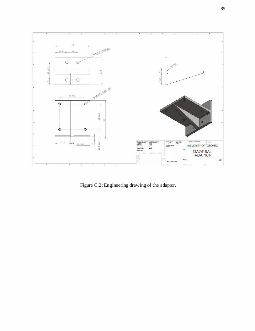
85
Figure C.2: Engineering drawing of the adaptor.

86
Appendix D – Engineering Drawings for Prototype III
Figure D.1: Engineering drawing of the base.

87
Figure D.2: Engineering drawing of the link.

88
Figure D.3: Engineering drawing of the mobile platform.

89
Appendix E – Engineering Drawings of the Revolute Joint
Assembly
Figure E.1: Engineering drawing of the central housing.

90
Figure E.2: Engineering drawing of the side housing.

91
Figure E.3: Engineering drawing of the shaft.

92
Appendix F – Inverse Kinematics of the 9-dof Redundant RmMT
Due to added redundancy, there is no closed-form kinematic solution to the 9-dof mechanism.
However, a kinematic model for performance evaluation can nevertheless be proposed.
As shown in Figure F.1, the 9-dof mechanism can be reduced to 6-dof by locking the sliders on
the curvilinear guide at the desired positions, which, in this case, the travel of the slider, , is
known. Then, for each set of , the 6-dof mechanism consists of three linear actuators which
move tangentially, and three linear actuators which move radially, with respect to the curvilinear
guide. Their travels are denoted by and respectively, which are the joint-space variables
of interest. The inverse kinematic solution for the 6-dof mechanism, which is a function of ,
can be solved, using similar procedures as in Section 2.2. Finally, the complete kinematic model
of the 9-dof mechanism can be established by calculating the inverse kinematics for all the
required sets of .
Figure F.1: Top view schematics of the 9-dof Redundant RmMT.