Embed Size (px)
Citation preview
Previous Issue: 30 June, 2003 Next Planned Update: 1 August, 2009 Page 1 of 45 Primary contact: R.A. Hartman on 873-2858
Engineering Standard
SAES-J-904 31 July, 2004 FOUNDATIONTM Fieldbus (FF) Systems
Instrumentation Standards Committee Members Al-Awami. L.H., Chairman Tuin, R.R., Vice Chairman Al-Dakhil, T.K. Al-Dhafeeri, F.T. Al-Khalifa, A.H. Al-Madhi, F.A. Alqaffas, S.A. Bogusz, Z.J. Ell, S.T. Fadley, G.L. Falkenberg, A.R. Gawargy, N.E. Grainger, J.F. Jumah, Y.A. Mahmood, B. Qarni, M.A. Trembley, R.J.
Saudi Aramco DeskTop Standards Table of Contents 1 Scope........................................................... 2 2 Conflicts and Deviations............................... 2 3 References................................................... 3 4 Definitions..................................................... 4 5 System Design............................................. 4 6 Wiring Design............................................... 10 7 Fieldbus Devices.......................................... 21 8 Non-Device Element Selection..................... 23 9 Host Control System Requirements............. 26 10 Instrument Asset Management System (IAMS)..................................... 29 11 Documentation............................................. 31 12 Factory Acceptance Test (FAT)................... 37
Document Responsibility: Instrumentation SAES-J-904 Issue Date: 31 July, 2004 Next Planned Update: 1 August, 2009 FOUNDATIONTM Fieldbus (FF) Systems
Page 2 of 45
Table of Contents (Cont'd) 13 Installation, Checkout and Precommissioning............................... 38 14 Maintenance Shop Fieldbus System and Tools............................................. 39 Appendix A – Fieldbus Glossary of Terms......... 41
1 Scope
1.1 This standard defines the requirement for design, specification, installation, configuration, commissioning and maintenance for FOUNDATION™ Fieldbus based control systems. This specification will only discuss the voltage mode (parallel coupling) 100 ohm medium attachment unit, as defined in IEC 61158-2, operating at a signal speed of 31.25 kilobits per second (i.e., H1).
1.2 FOUNDATION™ Fieldbus systems include instruments and host control systems that cover all applications and aspects of instrumentation and control. Therefore, all Saudi Aramco Instrumentation (J) and Control System (Z) standards apply to FOUNDATION™ Fieldbus systems.
1.3 A FOUNDATION™ Fieldbus based control system shall not be used for Emergency Shutdown and Isolation Systems.
1.4 This entire standard may be attached to and made a part of purchase orders.
2 Conflicts and Deviations
2.1 Any conflicts between this Standard and other applicable Saudi Aramco Engineering Standards (SAES's), Materials System Specifications (SAMSS's) Standard Drawings (SASDs), or industry standards, codes, and forms shall be resolved in writing by the Company or Buyer Representative through the Manager, Process & Control Systems Department of Saudi Aramco, Dhahran.
2.2 Direct all requests to deviate from this standard in writing to the Company or Buyer Representative, who shall follow internal company procedure SAEP-302 and forward such requests to the Manager, Process & Control Systems Department of Saudi Aramco, Dhahran.
Document Responsibility: Instrumentation SAES-J-904 Issue Date: 31 July, 2004 Next Planned Update: 1 August, 2009 FOUNDATIONTM Fieldbus (FF) Systems
Page 3 of 45
3 References
The selection of material and equipment, and the design, construction, maintenance, and repair of equipment and facilities covered by this standard shall comply with the latest edition of the references listed below, unless otherwise noted.
3.1 Saudi Aramco References
Saudi Aramco Engineering Procedures
SAEP-302 Instructions for Obtaining a Waiver of a Mandatory Saudi Aramco Engineering Requirement
SAEP-1634 Factory Acceptance Test
SAEP-1636 Installation and Checkout Plan
Saudi Aramco Engineering Standards
SAES-J-002 Technically Acceptable Instruments
SAES-J-003 Instrumentation - Basic Design Criteria
SAES-J-902 Electrical Systems for Instrumentation
SAES-Z-001 Process Control Systems
Saudi Aramco Materials System Specifications
23-SAMSS-010 Distributed Control Systems
34-SAMSS-913 Instrumentation and Thermocouple Cable
3.2 Industry Codes and Standards
The International Society for Measurement and Control
IEC 61158-2 Digital data communications for measurement and control – Fieldbus for use in industrial control systems - Part 2: Physical Layer Specification and Service Definition
ISA 5.1 Instrumentation Symbols and Identification
FF-569 Foundation™ Fieldbus Host Interoperability Support Test Procedures
National Fire Protection Association
NFPA 70 (2002) National Electrical Code 2002
Document Responsibility: Instrumentation SAES-J-904 Issue Date: 31 July, 2004 Next Planned Update: 1 August, 2009 FOUNDATIONTM Fieldbus (FF) Systems
Page 4 of 45
4 Definitions
4.1 All definitions of Fieldbus terms and acronyms used in this document can be found in appendix 'A'.
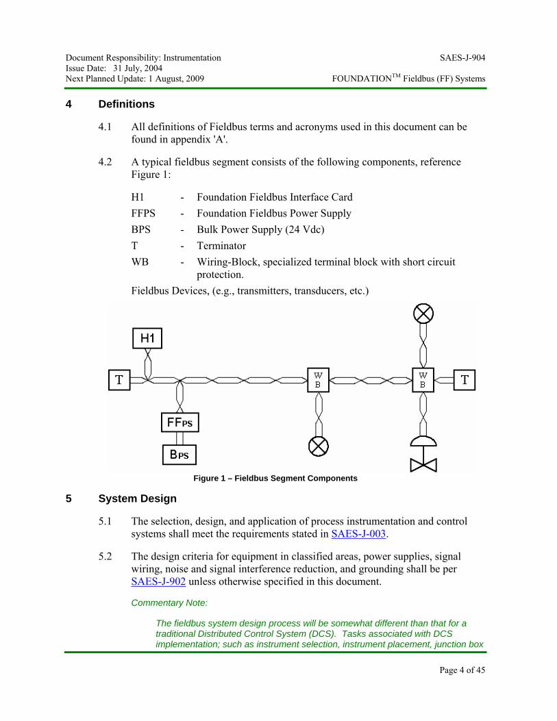
4.2 A typical fieldbus segment consists of the following components, reference Figure 1:
H1 - Foundation Fieldbus Interface Card FFPS - Foundation Fieldbus Power Supply BPS - Bulk Power Supply (24 Vdc) T - Terminator WB - Wiring-Block, specialized terminal block with short circuit
protection. Fieldbus Devices, (e.g., transmitters, transducers, etc.)
Figure 1 – Fieldbus Segment Components
5 System Design
5.1 The selection, design, and application of process instrumentation and control systems shall meet the requirements stated in SAES-J-003.
5.2 The design criteria for equipment in classified areas, power supplies, signal wiring, noise and signal interference reduction, and grounding shall be per SAES-J-902 unless otherwise specified in this document.
Commentary Note:
The fieldbus system design process will be somewhat different than that for a traditional Distributed Control System (DCS). Tasks associated with DCS implementation; such as instrument selection, instrument placement, junction box
Document Responsibility: Instrumentation SAES-J-904 Issue Date: 31 July, 2004 Next Planned Update: 1 August, 2009 FOUNDATIONTM Fieldbus (FF) Systems
Page 5 of 45
design, etc. are commonly completed independently of each other. This is not the case, however, for the design of a fieldbus based system. Since many traditional control functions can reside in fieldbus instruments, design considerations traditionally associated with the DCS must now expand to incorporate field instrumentation.
5.3 Basic Segment Loading Requirements
Commentary Note:
Prior to defining Fieldbus segments, the process control strategy should be complete, the P&IDs available, instruments selected, and instrument locations determined.
5.3.1 Redundant H1 interface cards shall be used for all segments.
Commentary Note:
The H1 interface cards are not to be counted as an FF device for segment loading design.
5.3.2 Ten percent (10%) spare H1 interface cards and FFPS shall be installed and wired to the marshalling cabinet terminal blocks.
5.3.3 Segments with final control elements shall contain 8 or fewer devices.
5.3.4 Segments containing monitor only devices (i.e., no final control elements) shall contain 12 or fewer devices. Note: Monitor only devices do not participate in any control function.
Commentary Note:
Use of function blocks, other than AI, PID, AO, are acceptable in the field device as long as the macrocyle timing requirements are met, see section 5.4.
5.3.5 Segments shall contain no more than 2 final control elements (i.e., control valves, modulating damper actuators, etc.). On-Off actuators, (i.e., air and motor operated valves – AOV's and MOV's), are not considered as 'final' control elements.
Commentary Note:
While the H1 segment might be able to support six or more control loops, other factors, such as number of function blocks, scan rates, risk assessment, etc. present limitations which dictate fewer.
5.3.6 Each segment shall have an enabled backup Link Active Scheduler (LAS) in a field device.
Document Responsibility: Instrumentation SAES-J-904 Issue Date: 31 July, 2004 Next Planned Update: 1 August, 2009 FOUNDATIONTM Fieldbus (FF) Systems
Page 6 of 45
Commentary Note:
The preferred location of the backup LAS is in a monitoring only (i.e., not used for control) field device.
5.3.7 The master and primary backup Link Active Scheduler (LAS) shall reside in the redundant H1 interface cards.
5.4 Control and Monitor Segment Macrocyle Rates
5.4.1 The maximum macrocyle time shall be one (1) second. Faster macrocyle times are acceptable and shall be used when the process dynamics require it.
5.4.2 Each segment shall operate with a single specified macrocycle execution time. Multiple macrocycles shall not be used on a single segment, even if available in the host control systems particular product.
5.4.3 The segment designer shall allocate sufficient unscheduled (free asynchronous) time as required by the host control system. The segment designer shall confirm engineered macrocyle times via actual configuration on the Host control system software.
Commentary Notes:
Function block execution frequencies must be compatible with both system loading and process control objectives. The execution frequency of all function blocks contained within a single fieldbus segment is defined by that segment's macrocycle time. This macrocycle time, which can typically range from 250ms to several seconds (depending on the nature of the application), is configured for each fieldbus segment. Some host control system's configuration products allow devices on the same segment to operate at different macrocycle times. However, backup LAS devices are not capable of managing these multiple macrocycles, so this feature may not be used. The order of execution should be automatically determined by the host control system's configuration software, based on the connections between function blocks on the fieldbus segment. If a faster control loop is added to a segment containing slower loops, then the macrocycle times of all devices residing on the segment must be adjusted to accommodate it. Some care should be exercised as the segment can become overloaded.
Note that the macrocycle contains unscheduled time required for non-deterministic bus communications, such as alarm transmission, setpoint changes, etc. The host control system's recommended unscheduled time should be allocated for each macrocycle. Note that the minimum may change based on how much bus required communication is configured as deterministic. While it is hoped that
Document Responsibility: Instrumentation SAES-J-904 Issue Date: 31 July, 2004 Next Planned Update: 1 August, 2009 FOUNDATIONTM Fieldbus (FF) Systems
Page 7 of 45
the host control system's configuration software will manage and maintain minimum unscheduled time, this is not necessarily true, and must be verified.
5.5 Requirements for Proportional-Integral-Derivative (PID) Control in the Field Device.
5.5.1 Single Loop PID Control in the Segment
5.5.1.1 For single PID control in the field device, all function blocks that make up that control loop must reside on the same segment. When all function blocks of a single PID control loop cannot reside on the same segment, the PID control shall reside in the host control system Controller.
5.5.1.2 When single loop PID control is implemented in the field device, the PID function block shall be located in the final control element.
Commentary Note:
Both the valve and transmitter typically have a PID block available, so locating the PID block in one device over another device is not a trivial issue. Issues such as execution speed, advanced diagnostics, failure mode, and operator access are generally considered when locating where the PID block resides. However, Saudi Aramco requires the PID block to be located in the control valve positioner. As with conventional control systems, loop and device failure modes need to be determined and the proper course of fail action identified for each control loop.
5.5.2 Split Range Control
The primary PID control shall reside in the Host control system Controller.
Exception:
If all function blocks (e.g., Splitter Block, AIs, PIDs, AOs, etc.) for split range control are available in the 'control loop' devices on the segment, then "primary PID control" may reside in one of the control devices.
5.5.3 Cascade Control
5.5.3.1 The preferred cascade control configuration is to locate all cascade loop function blocks and devices on the same segment. The primary PID controller shall reside in the
Document Responsibility: Instrumentation SAES-J-904 Issue Date: 31 July, 2004 Next Planned Update: 1 August, 2009 FOUNDATIONTM Fieldbus (FF) Systems
Page 8 of 45
primary measurement transmitter and secondary PID controllers shall reside in the secondary final element.
5.5.3.2 If the primary and secondary loops have devices or function blocks on separate segments, the primary PID control shall reside in the host control system Controller. In this case, the secondary loop PID control may reside in the secondary final element, if all secondary loop function blocks and devices reside on the same segment.
5.6 Final Element Configured Fail State
All final control elements shall have a configured fail-state on loss of segment communication.
Commentary Notes:
The valve has two different fail states depending on failure mode:
• configured fail state • mechanical fail-state.
Configured fail state may be open, closed, hold last value, or anything in-between. The valve will go to its configured fail state on loss of communication or upon a selected event. Loss of communication can be caused by:
• Accidental removal of terminator • Loss of H1 interface cards (PID function block in controller)
Selected event may be:
• Loss of Analog Input signal to the valve PID block • Process event (emergency trip) or diagnostic event (valve fault).
The valve will go to its mechanical fail-state position (i.e., spring return position) on loss of power. Loss of power can be caused by:
• Broken wire • Shorted wire • Failed FFPS • Loss of DC supply voltage to FFPS
5.7 Risk Assessment and Segment Loading
5.7.1 Each Saudi Aramco facility should identify and document a risk assessment philosophy (method) by which Fieldbus devices are assigned to segments. Existing plant risk area or I/O card loading methods in place may be used. The philosophy shall consider segment segregation, multiple segments per H1 interface card, etc. The risk
Document Responsibility: Instrumentation SAES-J-904 Issue Date: 31 July, 2004 Next Planned Update: 1 August, 2009 FOUNDATIONTM Fieldbus (FF) Systems
Page 9 of 45
assessment ranking shall be clearly shown on the Instrument Segment Diagram (ISD).
5.7.2 However, if no risk or I/O assignment philosophy is defined by the Saudi Aramco Operating (Proponent) Organization, the following control valve criticality rating and segment loading method shall be used.
5.7.3 "Critical" Control Valve
5.7.3.1 Failure of a critical control valve will result in a total system trip, causing a shutdown of the entire unit or other unavoidable losses in excess of $1,000,000.
5.7.3.2 Critical control valves and their associated measurement device (transmitter) shall reside on H1 segments with no other devices.
Exception:
The segment may contain two critical control valves and associated transmitters when services are dependent. Dependent means that either of the two (2) valves will trip the same unit or piece of equipment.
Commentary Note:
It is expected that Critical control valves will make up a small percentage (<10%) of the total number of plant control valves. Segments with Critical control valves will have limited devices and unavailable for future expansion.
5.7.3.3 Every ISD with a 'critical' control valve shall prominently show the following verbiage, "Critical Control Valve Segment" and "No additional devices shall be loaded (installed) on this segment". The location of this verbiage shall be in the same place for every critical control valve ISD.
Commentary Note:
ISDs without a "Critical Control Valve" rating are defined as 'non-critical', therefore devices may be added to these segments in the future. Non-critical ISDs do not have to be identified with special text.
5.8 FF Control Module & Function Block Naming
Document Responsibility: Instrumentation SAES-J-904 Issue Date: 31 July, 2004 Next Planned Update: 1 August, 2009 FOUNDATIONTM Fieldbus (FF) Systems
Page 10 of 45
5.8.1 Each Fieldbus control strategy or module will be named based on a reasonable and consistent format for the facility. The naming convention shall be reviewed by the Proponent, documented and be applicable to future projects.
5.8.2 Unless specified differently, each FF function block shall use a field device tag name for its main descriptive name and a 'suffix' defining the function or block type for which it is defined, (e.g., FT5010_AI, FT5010_AO, etc.).
5.8.3 In the event that a FF device has more than one identical function block, each shall be uniquely identified with a sequential numeral (e.g., FT5010_AI_1, FT5010_AI_2, etc.).
6 Wiring Design
6.1 Segment Topology
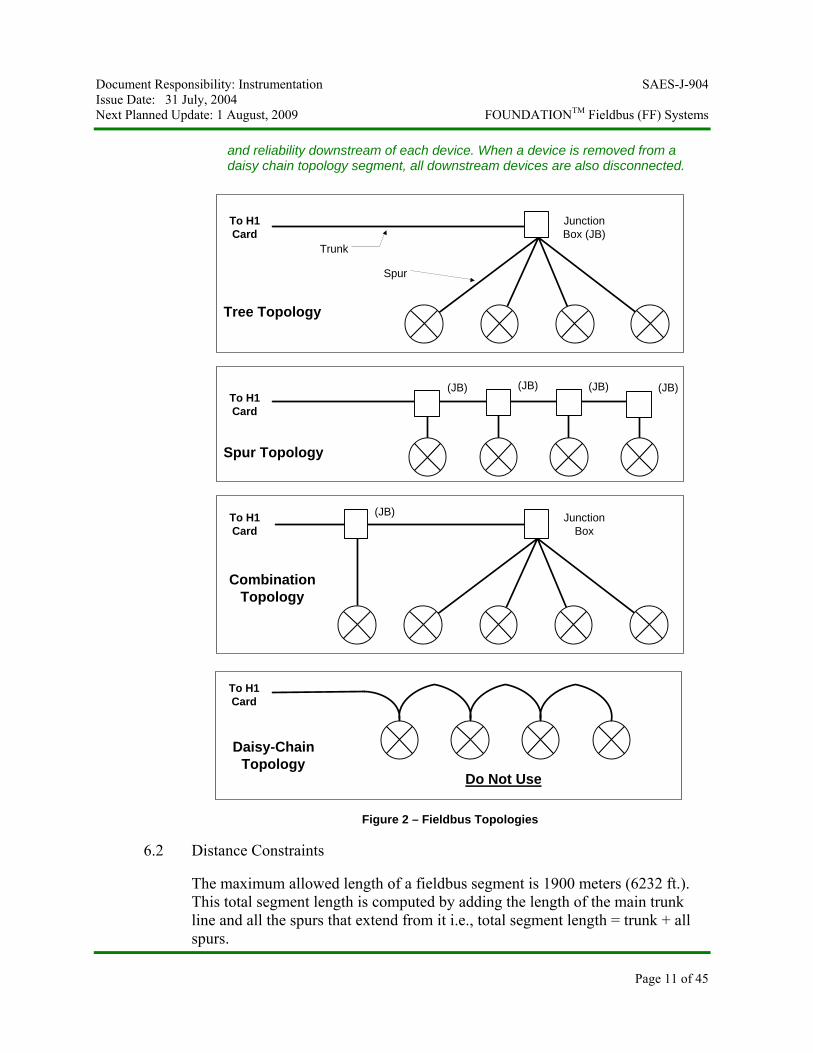
The fieldbus installation shall use the 'tree', 'spur', or 'combination' topology as shown in Figure-2. The daisy chain topology (i.e., routing the trunk directly through each device) shall not be used.
Commentary Notes:
Components of fieldbus segments can be connected together in various architectures known as topologies. The topology selected is usually driven by the physical device location in order to reduce installation costs. Hence, plot plans are used in addition to P&ID's and instrument indexes in the design of a fieldbus segment.
Most often, after the above design considerations are weighed, the following three topologies are used: (See Figure 2)
• A tree topology is used when several related instruments are physically located close to each other. A fieldbus junction box is located close to the instruments with spurs extending from it to each instrument.
• A spur topology is used when several related instruments are located in the same direction from the Host control system but not necessarily close to each other. In this case, a trunk line is extended from the host control system to the farthest instrument and spurs are extended from it as it runs past each instrument.
• A spur/tree topology is used when some combination of the above instrument locales exists. Note that spurs are permitted to extend only from trunk lines and not from other spur lines.
Daisy chain topology may appear to reduce total wiring run length and connection cost, but it has a significant disadvantage. That disadvantage is maintainability
Document Responsibility: Instrumentation SAES-J-904 Issue Date: 31 July, 2004 Next Planned Update: 1 August, 2009 FOUNDATIONTM Fieldbus (FF) Systems
Page 11 of 45
and reliability downstream of each device. When a device is removed from a daisy chain topology segment, all downstream devices are also disconnected.
Trunk
Spur
To H1Card
Tree Topology
JunctionBox (JB)
To H1Card
Spur Topology
To H1Card
JunctionBox
CombinationTopology
To H1Card
Daisy-ChainTopology
(JB) (JB)(JB)(JB)
(JB)
Do Not Use
Figure 2 – Fieldbus Topologies
6.2 Distance Constraints
The maximum allowed length of a fieldbus segment is 1900 meters (6232 ft.). This total segment length is computed by adding the length of the main trunk line and all the spurs that extend from it i.e., total segment length = trunk + all spurs.
Document Responsibility: Instrumentation SAES-J-904 Issue Date: 31 July, 2004 Next Planned Update: 1 August, 2009 FOUNDATIONTM Fieldbus (FF) Systems
Page 12 of 45
Commentary Note:
The maximum length given is specified in the IEC 61158-2 Fieldbus standard. From field experience we have found these lengths to be conservative. As stated in this specification, the length of a segment is limited by voltage drop and signal quality (i.e., attenuation and distortion).
6.3 Spurs
6.3.1 Only one (1) FOUNDATION™ Fieldbus (FF) device shall be connected to each spur.
Commentary Note:
Since we are using a short circuit protection wiring-block the segment design is limited to one (1) device per spur, reference section 6.5.3.
6.3.2 The maximum spur length shall be 120 meters (394 ft.). The spur length is the length of the cable from the wiring-block to the FF device.
Commentary Note:
A spur is a drop off of the main trunk line. The trunk is considered to be the main cable run and will contain segment terminators at each end.
6.3.3 All spur connections on the wiring-block shall be designed as Nonincendive (Ex nL) for use in Class I, Division 2, applicable Groups A, B, C and D; with Nonincendive Field Wiring (reference sections 6.5.3 and 6.13).
Commentary Note:
Having the spurs installed as "Nonincendive Circuits" with "Nonincendive Field Wiring", as defined in the NEC, allows 'live disconnect' of spur wires e.g., the maintenance technician can go directly to the FF device and lift, terminate, and short wires on a live spur without impacting other FF devices and without hazardous area gas clearance.
6.4 Cable Types
6.4.1 Trunk (Homerun) Cabling
6.4.1.1 Either Type 'A' cable as specified in section 12.8.2 of IEC-61158-2 or Aramco's standard 18 AWG multi-pair, individually shielded cable for analog signals, per 34-SAMSS-913 Group-4 cable specification, shall be used for all trunk wiring.
Document Responsibility: Instrumentation SAES-J-904 Issue Date: 31 July, 2004 Next Planned Update: 1 August, 2009 FOUNDATIONTM Fieldbus (FF) Systems
Page 13 of 45
Commentary Notes:
The 1900 meter design criteria is acceptable with Aramco's standard instrumentation cable or with Type-A cable i.e., you do not have to reduce the total segment length if you use Aramco standard Group-4 instrumentation cable.
18 AWG is the minimum wire size that may be used, larger wire sizes for the homerun cable are acceptable e.g., 16 AWG.
6.4.1.2 Twenty percent (20%) spare pairs shall be provided for all Fieldbus segment trunk cables, with a minimum of one spare pair. This requirement includes spares on trunk cable runs between marshalling racks and junction boxes and between field junction boxes.
Commentary Notes:
The decision to use multi-pair or single pair trunk cabling depends on the number of segments installed in the field junction box. Typically, the trunk cable will be a multi-pair cable if you have more than one segment in the junction box. Note that under all circumstances, there will be at least 2 Fieldbus trunk pairs run together (one active and one spare minimum).
From prior FF projects implemented at Saudi Aramco, the following trunk installation design is a cost effective solution: From the marshalling cabinet route a multi-pair cable (e.g., 12-24 pair) to an intermediate junction box. Note: This intermediate junction box only contains pass-through terminal blocks i.e., no wiring-blocks. From the intermediate junction box then route multi-pair cables (e.g., 2-6 pair) to outlying FF junction boxs. This method reduces the number of FF cables entering the PIB and reduces the total installed cost of the trunk cabling.
6.4.1.3 All multi-pair trunk cables shall contain only FF signals i.e., no other signal type is allowed in a trunk cable.
6.4.2 Spur Cables
Type 'A' cable (#18 AWG), as specified in section 12.8.2 of IEC-61158-2, shall be used for all spur cabling e.g., Belden YM46698.
6.4.3 Color Coding
6.4.3.1 For all FF cables, spur and trunk, the outer jacket color shall be orange.
Document Responsibility: Instrumentation SAES-J-904 Issue Date: 31 July, 2004 Next Planned Update: 1 August, 2009 FOUNDATIONTM Fieldbus (FF) Systems
Page 14 of 45
6.4.3.2 For all 'armored' FF cables, spur and trunk, the inner and outer jacket color of the armored cable shall be orange.
6.4.3.3 For all FF cables, spur and trunk, the conductor color code shall be;
(+ signal) black (- signal) white drain/shield bare tinned copper conductor
6.5 Field Junction Boxes
6.5.1 All trunk and spur connections in the field junction boxes, including pass through trunk pairs without spurs, shall be terminated on wiring-blocks specifically made for Foundation Fieldbus networks.
Exception:
Inactive spare Fieldbus trunk pairs shall be terminated on wiring-blocks or on conventional pass-through terminal blocks, per Saudi Aramco standards.
6.5.2 Initial design shall provide at least 25% spare 'spur' connections on the wiring-block(s) for each segment. For segments with multiple field junction box's, each junction box shall have at least 25% spare spur connections on the wiring-block(s).
Commentary Note:
For example, a segment with eight (8) FF devices connected in one (1) field junction box would require a minimum of 10 spur connections i.e., eight (8) for the FF devices and two (2) spare spur connections. One possible solution for the wiring-block design in the junction box is: one 10-spur wiring-block or one 8-spur wiring-block and one 2-spur wiring-block block. Note: If an 8-spur and 2-spur wiring block are used, all eight devices could be connected to one wiring-block or both wiring-blocks could be used for spur connections.
6.5.3 The wiring-block shall meet the following requirements:
6.5.3.1 Two (2) dedicated connections for the fieldbus homerun/trunk cable.
6.5.3.2 Trunk connections shall be rated nonsparking (nonarcing) i.e., Ex nA.
6.5.3.3 Integral short circuit protector for spur connections, maximum current to spur shall be no more than 60 mA.
Document Responsibility: Instrumentation SAES-J-904 Issue Date: 31 July, 2004 Next Planned Update: 1 August, 2009 FOUNDATIONTM Fieldbus (FF) Systems
Page 15 of 45
Commentary Note:
Wiring-blocks with integral spur short circuit protectors will prevent a fault (short circuit) in the device or spur cable run from bringing the entire FF segment down. On a fault condition, the maximum current delivered to a spur is ~60 mA. Therefore, for worst-case design where a Fieldbus device consumes 10mA quiescent current, an additional 50mA load is added when this spur is short-circuited.
6.5.3.4 Spur connections shall be rated nonincendive (energy limited) i.e., Ex nL and shall have 'live disconnect' capability.
6.5.3.5 CSA or FM approved Ex nA [nL]; Class I, Division 2, Groups B, C, D or Zone 2, IIA, IIB, IIC.
Commentary Notes:
A nonincendive circuit employs a protection technique that prevents electrical circuits from causing a fire or explosion in a hazardous (classified) location. Nonincendive circuits are sometimes referred to as intrinsically safe circuits for a Division 2 location. Nonincendive circuits and equipment are tested or evaluated essentially in the same way the intrinsically safe circuits and equipment are tested and evaluated, except that abnormal conditions are not considered. Because of its definition, a nonincendive circuit is a low-energy circuit.
Live work is permissible only on the current-limited spurs. Live work on the trunk is not permissible without gas clearance. For most all maintenance purposes this is acceptable, because work on the trunk is very rarely required.
6.5.3.5 Pluggable (removable) 'trunk' and 'spur' connectors with retaining screws.
6.5.3.6 LED indicator for each spur connection indicating when a spur is shorted and is in overcurrent mode.
6.5.3.7 LED to indicate when bus power is available.
6.5.3.9 Wire capacity: 12 - 24 AWG.
6.5.3.10 Temperature range -45 to +70°C.
6.5.3.11 DIN rail mounting.
Commentary Note:
The terminal block mounting rail (i.e., DIN rail) is defined by the following German and European industry standards:
Document Responsibility: Instrumentation SAES-J-904 Issue Date: 31 July, 2004 Next Planned Update: 1 August, 2009 FOUNDATIONTM Fieldbus (FF) Systems
Page 16 of 45
Top hat rail, 35 mm wide by DIN EN 50 022 (CENELEC EN 50 022); G-profile rail, 32 mm wide by DIN EN 50 035 (CENELEC EN 50 035).
6.5.4 A warning label must be prominently affixed on the junction box door (inside) stating the following: (red lettering with white background)
"WARNING: Explosion Hazard – Do not connect or disconnect the 'trunk connections' on the wiring-block unless power has been switched off or the area is known to be non-hazardous."
6.5.5 An information label must be prominently affixed on the junction box door (inside) stating the following: (black lettering with white background)
"The spur connections may be connected or disconnected while the circuit is live i.e., you may connect or disconnect the spur on the wiring-block or at the device without sniffing the area for combustible gasses."
6.5.6 The wiring-blocks shall be mounted vertically in the field junction box.
6.5.7 The DIN rail(s) in the junction box shall be designed with enough spare length to allow the future addition of one 8-spur or larger wiring-block.
6.5.8 Junction Boxes shall contain only FF signal wiring.
6.5.9 The junction box shall be a single door NEMA 4X box. The box construction shall meet the following requirements:
6.5.9.1 Type 316 stainless steel body, door and hardware.
6.5.9.2 Continuously welded seams, finished smooth.
6.5.9.3 Continuous stainless steel hinge with removable pin.
6.5.9.4 Stainless steel captive clamps.
6.5.9.5 Data/Print pocket on inside of door.
6.5.9.6 External mounting brackets.
6.5.9.7 Collar studs for mounting inside panel.
6.5.9.8 Ground stud for terminating A/C safety ground wire.
Document Responsibility: Instrumentation SAES-J-904 Issue Date: 31 July, 2004 Next Planned Update: 1 August, 2009 FOUNDATIONTM Fieldbus (FF) Systems
Page 17 of 45
6.5.9.9 Painted steel panel (back-pan); in 'severe corrosive environments' a stainless-steel panel shall be used.
6.5.10 All field junction boxes shall be mounted vertically i.e., the door shall open from left-to-right or from right-to-left.
6.5.11 Junction boxes having an internal volume exceeding 2,000 cm³ shall be provided with Type 300 Series stainless steel breather and drain fittings, or a combination breather and drain fitting.
6.6 Marshalling
6.6.1 The FF homerun cable marshalling shall be per the requirements specified in SAES-J-902, except for the following requirements:
6.6.1.1 The trunk (homerun) cable pairs, including spare pairs, shall be marshalled on pass-through terminal blocks. Fused or knife-switch terminal blocks shall not be used.
6.6.1.2 FF marshalling shall be on dedicated DIN rail(s) in the marshalling cabinet i.e., no other signal types shall be marshalled on the same DIN rail with the FF signals.
6.7 Wiring Polarity
Wiring polarity shall be maintained throughout the segment design and installation i.e., black (+), white (-), and barred tinned copper conductor (drain/shield).
Commentary Note:
Wiring polarity is critical because some fieldbus devices are polarity sensitive. Wired with the wrong polarity, a device may short-circuit the segment or simply not operate.
6.8 Field Wiring Technique
6.8.1 The FF device wiring terminations shall be as per requirements specified in SAES-J-902.
6.8.2 No modular wiring components shall be used, (i.e., passive multiport junctions (bricks), molded connector cordsets, plug in junction connectors, etc.).
6.9 Fieldbus Power Consumption
Document Responsibility: Instrumentation SAES-J-904 Issue Date: 31 July, 2004 Next Planned Update: 1 August, 2009 FOUNDATIONTM Fieldbus (FF) Systems
Page 18 of 45
6.9.1 Fieldbus devices may be powered either from the segment (bus), or locally powered, depending on the device design.
Commentary Note:
Bus-powered devices typically require 10-30 mA of current at between 9 and 32 volts.
6.9.2 The total current draw from all devices on the segment must not exceed the rating of the FFPS – ' FOUNDATION™ Fieldbus Power Supply'. The segment design must take into account:
6.9.2.1 Total device quiescent current draw.
6.9.2.2 One spur short circuit fault (i.e., ~50 mA additional current draw).
6.9.2.3 25% additional current load over and above that calculated from 6.9.2.1 and 6.9.2.2 above.
Commentary Note:
The acronym 'FFPS' will be used in lieu of 'fieldbus power supply' throughout this document to avoid confusion with the bulk power supply (BPS).
6.9.3 The number of bus powered (two-wire) devices on a segment is limited by the following factors:
6.9.3.1 Output voltage of the FFPS.
6.9.3.2 Current consumption of each device.
6.9.3.3 Location of device on the segment, (i.e., voltage drop).
6.9.3.4 Location of the FFPS.
6.9.3.5 Resistance of each section of cable, (i.e., cable 'type').
6.9.3.6 Minimum operating voltage of each device.
6.9.3.7 Additional current consumption due to one spur short circuit fault, ~50 mA.
6.9.3.8 25% spare current capacity.
Commentary Note:
Document Responsibility: Instrumentation SAES-J-904 Issue Date: 31 July, 2004 Next Planned Update: 1 August, 2009 FOUNDATIONTM Fieldbus (FF) Systems
Page 19 of 45
The length of a fieldbus wiring system and the number of devices on a segment are limited by power distribution, attenuation and signal distortion. The IEC 61158-2 estimates how long a fieldbus cable can be and still have adequate signal quality, (i.e., acceptable attenuation and distortion). Calculating power distribution for a segment is relatively simple and can be easily performed.
6.10 Voltage Drop
Circuit analysis shall be carried out for each fieldbus segment to determine the operating voltage at each device. The calculated voltage at the device shall exceed the devices minimum voltage rating by 4 volts, (e.g., minimum Vdc required by device = 9 volts, therefore the calculated minimum voltage seen at the device shall be 13 Vdc). The calculated voltage at each device shall be shown on the Instrument Segment Diagram (ISD).
Commentary Notes:
The additional 4-volts at each device has been specified as a spare power margin for future device additions to the segment.
Per the FOUNDATION fieldbus specification, field devices must sense a DC voltage between 9 and 32 volts for proper operation.
The power used by fieldbus devices varies by device type and manufacturer. Specific minimum voltage and current requirements are contained in the product specifications for each device. The voltage and current requirement for each device shall be taken into consideration while conducting the circuit analysis of the segment. A Fieldbus FOUNDATION certified device is required to be capable of operating at > 9 Vdc.
6.11 Shielding
Fieldbus cable shield terminations shall be per requirements specified in SAES-J-902.
Commentary Note:
As with conventional analog signal shields, FF signal shields shall be grounded at one point only.
6.12 Grounding
Field instruments and instrument stands shall be grounded per requirements specified in SAES-J-902.
6.13 Wiring Practices to Meet Electrical Hazardous Area Rating
6.13.1 Class I Division 2 Areas (and Zone 2)
Document Responsibility: Instrumentation SAES-J-904 Issue Date: 31 July, 2004 Next Planned Update: 1 August, 2009 FOUNDATIONTM Fieldbus (FF) Systems
Page 20 of 45
6.13.1.1 'Nonincendive Field Wiring', as defined in Article 501.4(B)(3) – Div. 2 or 505.15(C)(g) – Zone 2 of NFPA 70 National Electrical Code, shall be used for the wiring method from the wiring-block spur connection to the FF device.
6.13.1.2 Nonincendive field wiring systems shall be installed in accordance with the wiring-block manufacturer's nonincendive control drawing(s). The segment designer shall use the 'control drawing' to validate that the voltage, current, capacitance and inductance parameters from the power source (wiring-block spur connection) to the power receiver (FF device) are in compliance with the manufactures limits.
Commentary Note:
Connected capacitance is the terminal capacitance of the receiver (FF device) plus any cable capacitance.
Connected inductance is the terminal inductance of the receiver (FF device) plus any cable inductance.
6.13.1.3 The spur cabling shall be mechanically protected by installation in a conduit system or by the use of armored cable. Installation of either method shall be per the requirements in SAES-J-902.
6.13.1.4 All other electrical and electronic equipment and wiring systems associated with the FF system shall be installed per SAES-J-902 e.g., homerun cables, cable trays, junction boxes, etc.
6.13.2 Class I Division 1 Area (and Zone 1):
Explosion proof technique shall be used for Class I – Division 1 (and Zone 1) electrical hazardous areas.
Exception:
Intrinsically Safe (IS) systems may be used with prior written permission from Supervisor, Instrumentation Unit/PID/P&CSD.
Commentary Note:
The IS design that P&CSD would consider acceptable is the use of a wiring-block that accepts the higher power trunk cabling but has spur connections that are rated as IS.
Document Responsibility: Instrumentation SAES-J-904 Issue Date: 31 July, 2004 Next Planned Update: 1 August, 2009 FOUNDATIONTM Fieldbus (FF) Systems
Page 21 of 45
6.13.3 Zone 0 Areas
Intrinsically Safe systems shall be used for Zone 0 applications.
7 Fieldbus Devices
7.1 Fieldbus Device Minimum Requirements
7.1.1 The following shall be the minimum 'features' available in all Fieldbus devices:
7.1.1.1 FOUNDATION Fieldbus Certification as having passed the latest revision of the Interoperability Test Kit (ITK).
7.1.1.2 The FF Device and all function blocks shall be tested and certified by the host control system vendor.
7.1.1.3 Function blocks shall be downloadable into the devices by the end user.
7.1.1.4 Capable of performing continuous diagnostics, including self-test functions, to provide specific diagnostic information at the Man Machine Interface (MMI).
7.1.1.5 All Fieldbus instruments shall include menu's and method's (wizards) to allow easy set-up and calibration from the MMI.
Exception:
Fieldbus instruments without menu's and method's capability may be accepted with prior written permission from Supervisor, Instrumentation Unit/PID/P&CSD.
7.1.2 All FF devices (instruments) shall be purchased from the technically acceptable instrument manufacturers listed in SAES-J-002.
7.1.3 All FF devices (terminated to the spur connector on the wiring-block) installed in a Class I Division 2 (Zone 2) area shall be certified as "Nonincendive" by one of the following agencies:
7.1.3.1 Factory Mutual Research Corp. (FM).
7.1.3.2 Canadian Standards Association (CSA).
7.1.3.3 ATmosphere EXplosible (ATEX).
Document Responsibility: Instrumentation SAES-J-904 Issue Date: 31 July, 2004 Next Planned Update: 1 August, 2009 FOUNDATIONTM Fieldbus (FF) Systems
Page 22 of 45
7.1.4 For each type of nonincendive device used, a scanned copy of the 'certificate of compliance' showing the nonincendive field wiring parameters shall be submitted to Saudi Aramco in the Foundation Fieldbus Segment Calculator (FFSC), reference section 11.5.9.
7.2 Multi-Input Transmitters
7.2.1 Multi-input and multi-variable transmitters using FOUNDATION Fieldbus Analog Input (AI) function block(s) may be used for control and monitoring. Each multi-variable transmitter shall be used in one control loop only. All other variables shall be used for monitor only applications.
7.2.2 Multi-input transmitters using FOUNDATION Fieldbus Multiple Analog Input (MAI) function block(s) shall be used for monitor only applications.
Commentary Note:
In conventional control systems, temperature is most often measured with wire-direct architecture, where the RTD or thermocouple is wired to a junction box, then to the DCS input cards via a home-run, multi-pair cable. The longer the wire runs for wire-direct measurement, the more the savings from using the multi-input transmitter.
7.3 Multi-Output Transmitters
Multi-output transmitters using FOUNDATION Fieldbus Multiple Analog Output (MAO) function block(s) may be used for monitoring and control. Use of multi-output transmitters shall not constitute relief from the 'segment design' criteria specified in Section 5.
7.4 Multi-Input/Output Devices
Multi-input/output devices using FOUNDATION Fieldbus Analog Input (AI), Analog Output (AO), Discrete Input (DI) and Discrete Output (DO) function block(s) may be used for monitoring and control. Each multi-I/O device shall be used in one control loop only. All other I/O used, shall be for monitor and status only.
Commentary Note:
An MOV or AOV is a typical multiple analog and discrete input/output device. This device and its function blocks should be used in only one control scheme.
7.5 Discrete Fieldbus Devices
Document Responsibility: Instrumentation SAES-J-904 Issue Date: 31 July, 2004 Next Planned Update: 1 August, 2009 FOUNDATIONTM Fieldbus (FF) Systems
Page 23 of 45
Discrete FF devices (using DI/DO function blocks) may be used on the same segment as regulatory control and monitoring devices, (i.e., AI, PID, AO, etc.).
7.6 Conventional I/O on a Segment
Conventional analog or discrete I/O cards with integrated FOUNDATION fieldbus communications shall not be used without prior approval from the Supervisor, Instrumentation Unit/PID/P&CSD.
Commentary Note:
Remote I/O chassis's should be used to connect conventional I/O to the Host control system. This will facilitate the distributed control system methodology.
7.7 Valve Positioners
Single-acting digital valve positioners (single port) shall not be used on double-acting actuators for sliding-stem or rotorary-shaft valves.
Commentary Note:
The current solution, by some digital valve positioner manufacturers, is to provide a single-acting positioner with a reversing relay in the pneumatic tubing for double-acting actuators. This solution is not acceptable due to; additional complexity, difficulty in calibration, additional maintenance, additional spare parts, etc.
8 Non-Device Element Selection
8.1 Foundation Fieldbus Power Supplies (FFPS)
8.1.1 FFPS are required for each fieldbus segment.
8.1.2 FFPS shall be redundant and output current limited.
Commentary Note:
If an ordinary power supply were to be used to power the Fieldbus, the power supply would absorb signals on the cable because it would try to maintain a constant voltage level. For this reason, an ordinary power supply has to be conditioned for fieldbus. This is done by putting an inductor between the power supply and the fieldbus wiring. The inductor lets the DC power pass but prevents signals from going into the power supply. In practice, a real inductor is not used but an electronic equivalent. The electronic inductor circuit has the added advantage of limiting the current provided to the segment if the cable is shorted.
8.1.3 FFPS shall have redundant input power connections.
Document Responsibility: Instrumentation SAES-J-904 Issue Date: 31 July, 2004 Next Planned Update: 1 August, 2009 FOUNDATIONTM Fieldbus (FF) Systems
Page 24 of 45
8.1.4 FFPS shall be hot-swappable i.e., the power conditioning module can be replaced without interrupting power or communication on the fieldbus segment.
8.1.5 FFPS shall provide galvanic isolation of ≥ 250 Vac between the fieldbus segment and the input power supply i.e., Bulk Power Supplies (BPS).
8.1.6 Two separate, independent, fused circuits shall source power to the FFPS. One (1) circuit shall be powered from the primary bulk power supply and the second (2) circuit shall be powered from the secondary (redundant) bulk power supply.
8.1.7 FFPS units may be ganged together with common BPS feeds, and common alarms, for efficiency. No more than eight (8) FFPS units may be 'ganged' together. The primary and secondary BPS shall feed both ends of the ganged FFPS.
Commentary Note:
Some manufacturer's redundant power supplies (FFPS) can be ordered with pre-made wiring jumpers. These jumpers are used to efficiently distribute power and to series alarms to multiple (ganged) FFPS units. In this way, a gang of redundant FFPS may be fed from two primary and two secondary BPS feeds.
8.1.8 Failure or faults in any of the redundant FFPS shall be annunciated in the Host control system. A common alarm for all FFPS in a single cabinet may be used. Alternatively the FFPS alarms may be integrated into the H1 interface module and be annunciated as a system alarm.
8.2 Terminators
8.2.1 Each fieldbus segment must have exactly two terminators. The wiring between the two terminators is defined as the trunk.
8.2.2 All terminators located in the field shall be installed in a junction box. No terminators shall be installed in the FF devices.
Commentary Notes:
When a signal travels on a cable and encounters a discontinuity, such as a wire open or short, it produces a reflection. The portion of the signal that echoes from the discontinuity travels in the opposite direction. The reflection is a form of noise that distorts the signal. A terminator is used to prevent a reflection at the ends of a fieldbus cable. A fieldbus terminator consists of a 1μF capacitor in series with a 100 Ω resistor.
Document Responsibility: Instrumentation SAES-J-904 Issue Date: 31 July, 2004 Next Planned Update: 1 August, 2009 FOUNDATIONTM Fieldbus (FF) Systems
Page 25 of 45
Some of the wiring components previously discussed may have terminators built into them, (e.g., FFPS). These terminators may be permanently installed, turned on or off using a dipswitch, or placed into use by a wiring jumper.
8.3 Bulk Power Supplies (BPS)
8.3.1 The 24 Vdc BPS shall be redundant.
Commentary Note:
FFPS require an input voltage of 20 – 35 Vdc. Unless an appropriate 'DC' bus exists in the plant, the BPS provides the power conversion from 240/120 VAC to 24 VDC.
8.3.2 Two separate, independent, UPS circuits shall source power the redundant BPS. The UPS distribution panel shall be considered the common point where these two separate circuits originate.
8.3.3 Overcurrent protection shall be provided for each feed supplying power to an individual or gang of FFPS.
8.3.4 The negative leg of the BPS shall be grounded.
8.3.5 The BPS may be either dedicated solely to the fieldbus network or shared between the fieldbus network and conventional I/O.
8.3.6 If the site has an existing power supply for conventional 4-20 mA instrumentation, this power supply may be used to supply the FFPSs. The available spare capacity of the power supplies shall be verified to meet the FFPS demands. The Proponent Organization representative shall approve, in writing, the use of the existing power supply.
8.4 Repeater
If a segment (network) needs to extend further than the 1900 meter length constraint, then a repeater may be considered. The repeated segment design must be reviewed and approved in writing from the Supervisor, Instrumentation Unit/PID/P&CSD.
Commentary Note:
Using a repeater to extend the segment length shall not be a standard design practice. In the cases where it is economically justified, a repeater may be considered to extend the total segment length. This would typically be in cases where the H1 interface card cannot be located relatively close to the process, (e.g., flare systems).
Document Responsibility: Instrumentation SAES-J-904 Issue Date: 31 July, 2004 Next Planned Update: 1 August, 2009 FOUNDATIONTM Fieldbus (FF) Systems
Page 26 of 45
9 Host Control System Requirements
In addition to the FF requirements specified in this document, Host control systems shall meet all requirements specified in SAES-Z-001, "Process Control Systems', and 23-SAMSS-010, "Distributed Control Systems".
9.1 Host Control System FF Interoperability
9.1.1 All FF Host control systems shall have completed Host Interoperability Support Testing (HIST) at FOUNDATION Fieldbus facilities, based on HIST Procedures document FF-569. FF Host control systems shall support all features specified in the HIST. The use of an FF Host systems that does not support all HIST features, may be used when approved in writing by the General Supervisor, PID/P&CSD, after a thorough review of the Host limitations.
9.1.2 A letter of conformance to the Host Interoperability System Test shall be provided to verify test completion and feature support.
9.1.3 All supported FF HIST features shall be integrated seamlessly into the existing control system's engineering, configuration, maintenance, and operations system.
9.1.4 The Host System supplier shall have an interoperability test laboratory setup to ensure that all third party devices used in the project have been successfully tested and certified with their system, reference section 7.1.1.2.
9.2 Host FF Integration Features
9.2.1 All Host control system FF functions, including engineering, configuration, maintenance, and operational display functions, shall be integrated into a single, seamless Host control system.
9.2.2 Engineering, configuration, maintenance and operational features shall apply consistently and seamlessly to conventional analog or discrete I/O, smart HART and proprietary I/O, bus based I/O, and FF systems.
9.2.3 Separate software tools, displays, or procedures - specific for FF and different from conventional - are not acceptable.
9.2.4 Internal mirror or shadow function blocks used by control systems to map FF function blocks to internal proprietary function blocks must be completely transparent to the operator. Operating displays must use single, unique and independent tag names. Duplicate tag names for the same function are not acceptable.
Document Responsibility: Instrumentation SAES-J-904 Issue Date: 31 July, 2004 Next Planned Update: 1 August, 2009 FOUNDATIONTM Fieldbus (FF) Systems
Page 27 of 45
9.2.5 FF function block operation, including use of data quality, status, windup and bad value indication and mode switching, must be supported by, and transparently integrated into the control system operation and operating displays. Differences in operation or displays between FF devices or loops and conventional loops are not acceptable.
9.2.6 FF process alarms and device alerts must be supported by, and integrated into the control system. Differences between conventional and FF alarm management and alarm displays are not acceptable.
9.2.7 FF trend data via trend objects shall be supported by the Host control system and transparently integrated into real-time and historic trends displays.
9.3 Host-To-Device Revision Download Capability
Host control systems shall have the capability to download software revisions to FOUNDATION Fieldbus devices.
9.4 Host Control System Configuration Features
9.4.1 Host control system FF configuration shall be consistent in method and 'look and feel' with conventional configuration.
9.4.2 Internal mirror or shadow function blocks used by control systems to map FF function blocks to internal proprietary function blocks must be completely transparent to the configurator and operator. Single, unique and independent function block and parameter tag names must be used for both configuration and operation. Duplicate shadow blocks/parameters with tag names different from FF block/parameters are not acceptable.
9.4.3 The Host control sytem FF configuration tool shall seamlessly and transparently integrate with, and maintain, the master configuration database. Saves, restores and partial downloads of the master control system database shall be seamlessly and transparently accomplished for both FF and conventional control strategies by the same configuration tool.
9.4.4 The Host control sytem configuration tool shall have the following capabilities:
9.4.4.1 Offline FF configuration, e.g., to configure FF strategies with no segment or FF devices connected.
Document Responsibility: Instrumentation SAES-J-904 Issue Date: 31 July, 2004 Next Planned Update: 1 August, 2009 FOUNDATIONTM Fieldbus (FF) Systems
Page 28 of 45
9.4.4.2 The Host control system shall be capable of configuring all FF function blocks and parameters and support of Device Description (DD) services and Common File Format (CFF) specification.
9.4.4.3 Soft simulating and testing any and all FF control strategies.
9.4.4.4 Importing non-native, bulk configuration data for developing configuration of larger project databases.
9.4.4.5 Simple or complex online FF control strategy creation or modification.
9.4.4.6 Provide alerts and messages for FF configuration errors.
9.4.4.7 Transparently managing the macrocycle schedule including maintaining minimum unscheduled acyclic time, coordinating integration of proprietary and FF function block execution times.
9.4.4.8 Partial or incremental downloads to target function blocks and link schedulers without disrupting the operating segment strategies.
9.4.4.9 Master database saves and restores of targeted strategies or FF segments.
9.5 Host Control Sytem Commissioning and Maintenance Functions
9.5.1 The Host control system shall be capable of commissioning, setup, and maintaining all FF devices. This function must be integrated into the Host and available from Host workstations. The following functions shall be supported:
9.5.1.1 Add a new FF device to a segment. Add a future FF device to a segment through use of placeholder templates.
9.5.1.2 Move FF devices from/between offline, spare, standby, commissioned, and mismatch states and manage all address changes transparently. Manual address changes shall not be required.
9.5.1.3 Simple and complex commissioning functions including transmitter range changes, zeroing, and control valve positioner setup.
Document Responsibility: Instrumentation SAES-J-904 Issue Date: 31 July, 2004 Next Planned Update: 1 August, 2009 FOUNDATIONTM Fieldbus (FF) Systems
Page 29 of 45
9.5.1.4 Support for DD methods and menu's (wizards) for all maintenance functions to walk technicians through the necessary maintenance procedures.
9.5.1.5 Provide specific maintenance displays, organized in a logical manner, for all FF devices using English language descriptors and definitions with access to all parameters. Screens shall not use lists of FF function block parameters.
9.5.1.6 Ability to mirror existing FF device configuration (all FBs and parameters) onto a new FF device to allow quick device replacements.
9.5.1.7 Display of commissioning and maintenance screens shall be from the operator/engineering workstation.
9.5.1.8 Ability to perform device replacement without disturbing other devices on a segment.
10 Instrument Asset Management System (IAMS)
10.1 An Instrument Asset Management System, either integrated or separate from the host control system operator/engineering workstation, shall be provided for device configuration, documentation, calibration, and diagnostics.
Commentary Note:
An Instrument Asset Management System (IAMS) is sometimes refered to as a Plant Resource Manager (PRM) or an Asset Management System (AMS).
10.2 The IAMS software shall communicate to HART and FF field devices from various manufacturers.
10.3 The IAMS shall have the following functions and features as a minimum:
10.3.1 Automatically and continuously monitor the status, events and operating conditions of the field-connected devices without interfering with the plant control system.
10.3.2 Automatically send device alerts to maintenance personnel via email.
10.3.3 Connect and configure instruments and valves online.
10.3.4 Valve diagnostic tests shall include dynamic error band, drive signal, output signal, step response, and signature curve; all shall be presented in graphical and statistical data format.
Document Responsibility: Instrumentation SAES-J-904 Issue Date: 31 July, 2004 Next Planned Update: 1 August, 2009 FOUNDATIONTM Fieldbus (FF) Systems
Page 30 of 45
10.3.5 Access current device information from connected devices to determine their health and view process variables.
10.3.6 Perform device diagnostics with the results documented in the IAMS.
10.3.7 Store offline configurations in the database.
10.3.8 Connect to a device and download the offline configuration change(s) to the device.
10.3.9 Associate or attach electronic data sheets, drawings, scanned documents (e.g., pdf) and notes to a specific device.
10.3.10 Cut, copy, paste, or enter information about a specific device in a 'notes' area.
10.3.11 All instrument parameter changes and maintenance activities shall be automatically recorded by the software.
10.3.12 Export information to a Microsoft Excel file.
10.3.13 A common database for all IAMS data.
10.3.14 Multi-level password security. A system administrator shall establish user names and passwords that allow specific individuals access to different IAMS features.
10.4 For every valve with a digital valve positioner on the project, valve signature curves from the manufacturer shall be loaded into the IAMS database before FAT.
10.5 The IAMS system shall be in an easy-to-utilize state at mechanical completion of the project i.e., before operation of the plant begins. As a minimum, the following tasks shall be done to achieve this state.
10.5.1 The IAMS database shall be fully populated with device data for every device on the project.
10.5.2 Attach or associate the applicable Instrument Specification Sheet (ISS) to each device.
10.5.3 Attach or associate the applicable Instrument Segment Diagram (ISD) or Instrument Loop Diagram (ILD) to each device.
10.5.4 Obtain approval in writing from the Proponent Representative that the IAMS is fully commissioned and operational.
Document Responsibility: Instrumentation SAES-J-904 Issue Date: 31 July, 2004 Next Planned Update: 1 August, 2009 FOUNDATIONTM Fieldbus (FF) Systems
Page 31 of 45
11 Documentation
FOUNDATION Fieldbus system design requires the same documentation as conventional control system designs. However, some documents must be altered for FOUNDATION Fieldbus architecture. Documentation alterations, additions, and deletions required for FF use are defined below.
11.1 Control Philosophy Document
11.1.1 A control philosophy guideline document shall be created for all FF projects. The guideline shall define all typical control strategies, with control modules, function blocks and all parameter configurations defined. This guideline shall set function block and control module philosophy for this and future FF projects at the facility.
11.1.2 As part of the guideline, a narrative shall be provided for each typical function block and control module, to describe in detail the parameter setting and subsequent blocks/module operation. Included shall be narrative discussion on parameter configuration and operation for signal 'status', bad value determination, failure mode switching, initialization feature, anti-reset windup feature, etc. The guideline shall highlight any differences in configuration or operation between FF and non-FF control strategies.
11.1.3 The control philosophy guideline document shall include a risk assessment philosophy (method) which defines how and why specific Fieldbus devices are assigned to segments. The philosophy shall include consideration for segment loading constraints and multiple segments per H1 interface card. See section 5.7 for risk assessment and segment loading criteria.
11.2 Piping and Instrumentation Diagrams (P&ID's)
11.2.1 Fieldbus instrumentation shall be shown on the P&ID per Saudi Aramco standards with the following exceptions:
11.2.1.1 Fieldbus instrument balloons shall be conventional, with the addition of a Foundation Fieldbus indication on the top right side of the instrument bubble, shown as: FF
11.2.1.2 The line symbology for FF signal wiring shall be the standard 'dashed' electric signal per ISA 5.1.
Commentary Note:
Document Responsibility: Instrumentation SAES-J-904 Issue Date: 31 July, 2004 Next Planned Update: 1 August, 2009 FOUNDATIONTM Fieldbus (FF) Systems
Page 32 of 45
The proposed ISA line symbology for FF signal wiring is a double dash with an open bubble "- - o - - o - - o - -". To date, the newly revised standard (ISA 5.1) has not been approved. It is felt that an FF-in-a-box next to the instrument bubble is sufficient to clearly identify a FF device. The double-dash-open-bubble line symbol will congest the P&ID without adding value.
11.2.1.3 The control or logic function balloons shall be shown independent of the hardware in which it is contained.
Commentary Note:
PID, selectors, or arithmetic function blocks shall be shown functionally on the P&ID, (i.e., not shown as a shared balloons with the device they reside in).
11.2.2 All functions within the same field device shall be tagged with the same number, with individual function lettering appropriate for the application.
Commentary Note:
For example using a multi-variable Coriolis meter, the instrument tagging would be FT-1010, DT-1010, and TT-1010 for flow, density and temperature, respectively.
11.2.3 Multivariable Fieldbus transmitters (e.g., multiple process measurements from the same transmitter) shall be represented with connected instrument balloons.
Commentary Note:
For an 8 point Temperature Transmitter (TT) the tagging convention should use a suffix e.g., TT-100-A, TT-100-B, … TT-100-H. For a device that has different PV measurements, e.g., a Coriolis meter – the tagging convention should be our standard parallel numbering convention e.g., PT-100, TT-100, DT-100 (density), etc.
11.3 Instrument Segment Diagrams
The Instrument Loop Diagram (ILD) shall be replaced with an Instrument Segment Diagram (ISD). The ISD is a hardware-wiring diagram intended to show the physical connections and layout of the segment. Soft data including display, function block, and configuration data shall not be shown. In addition to standard loop drawing information, ISDs shall include the following FF system details:
Commentary Note:
Document Responsibility: Instrumentation SAES-J-904 Issue Date: 31 July, 2004 Next Planned Update: 1 August, 2009 FOUNDATIONTM Fieldbus (FF) Systems
Page 33 of 45
For a sample ISD please contact the Supervisor, Instrumentation Unit/PID/P&CSD.
11.3.1 The title block shall contain a 'segment name'. For some host control systems, the segment name shall consist of the "Controller Name, Card Number and Port Number". For example if the Controller name is '01', card number is '08' and we are using Port 1, the segment name will be ISD-010801. For other host control systems, the segment name shall consist of "Domain, Station, Node, Slot and Port Number".
Commentary Note:
The intent of this section is for the ISD 'segment name' to contain enough information so that the engineering/maintenance personnel can easily locate the physical location of the port that the segment is terminated on.
11.3.2 All segment connections inclusive of the H1 interface card, BPS, FFPS, field devices, terminations, junction boxes, and terminators.
11.3.3 All segment and field device tagging.
11.3.4 All spur cables shall be labeled with the instrument tag number i.e., source/destination (to/from) wire tagging per SAES-J-902.
11.3.5 All cable distances i.e., spur(s) and homerun (trunk).
11.3.6 Voltage drop calculation results at wiring-block(s) and at each device.
11.3.7 The Backup LAS device shall be identified.
11.3.8 Terminator locations shall be clearly identified.
11.3.9 Critical Control Valve verbiage if required, reference section 5.7.3.3.
Exception:
If the Saudi Aramco Operating (Proponent) Organization is using their own risk assessment philosophy to assign devices to the segment. Then their risk assessment ranking shall be clearly shown on the ISD, reference section 5.7.1.
11.4 Instrument Specification Sheets (ISS)
FOUNDATION Fieldbus instrumentation shall use the standard Saudi Aramco ISS's, with the following line item additions:
11.4.1 LAS capable (yes/no)
Document Responsibility: Instrumentation SAES-J-904 Issue Date: 31 July, 2004 Next Planned Update: 1 August, 2009 FOUNDATIONTM Fieldbus (FF) Systems
Page 34 of 45
11.4.2 Minimum Operating Voltage (Vdc)
11.4.3 Quiescent Current Draw (mA)
11.4.4 Polarity Sensitive Termination (yes/no)
11.4.5 DD revision level
11.4.6 Channel number and Description, (e.g., Channel 1 - Sensor 1, Channel 2 - Body Temperature, Channel 3 - Sensor 2, etc.).
11.4.7 Function Blocks Available, (e.g., AI_1, AI_2, PID_1, etc.)
Commentary Note:
For some host control system vendors, it also advisable to include the following line items on the ISS form: 'Device Tag', 'Node Address', and 'Device Class'. These line items are typically completed through a collaborative effort between the Host control system configuration contractor and the device manufacturer.
For a sample ISS's, illustrating the above information, please contact the Supervisor, Instrumentation Unit/PID/P&CSD.
11.5 Foundation Fieldbus Segment Calculator (FFSC)
11.5.1 The 'Engineering Design Contractor' shall develop a Microsoft Excel spreadsheet that will automatically calculate the voltage drop to the wiring-block(s) and to each device on the segment. In addition, the spreadsheet shall show, nonincendive calculations, which device is LAS enabled (i.e., backup LAS), and generate the 'output data' listed below.
Commentary Note:
For a sample FFSC, please contact the Supervisor, Instrumentation Unit/PID/P&CSD.
11.5.2 The FFSC shall be capable of managing all the different topologies (tree, spur, or combination) used in the project. The topology used shall be shown on each segment report generated.
11.5.3 The FFSC shall be set up to accept 16 devices per segment.
Commentary Note:
Even though Saudi Aramco only allows 8 devices per segment with final control elements and 12 devices in monitor only segments, as we gain field experience with FF we may want to add additional FF devices
Document Responsibility: Instrumentation SAES-J-904 Issue Date: 31 July, 2004 Next Planned Update: 1 August, 2009 FOUNDATIONTM Fieldbus (FF) Systems
Page 35 of 45
in the future i.e., more than our 8 and 12 device limit. Therefore, we want the FFSC to be able to accommodate a full segment i.e., 16 devices.
11.5.4 If any of the design parameters (e.g., spur length, total segment length, voltage drop, number of devices on segment, etc.) exceeds their defined acceptable range, then the cell fill color shall change to red.
11.5.5 The FFSC shall validate that the voltage, current, capacitance and inductance parameters from the power source (wiring-block spur connection) to the power receiver (FF device) are in compliance with the manufactures limits, reference section 6.13. The wiring-block manufacturers control drawing(s) shall be embedded, in viewable format, in the FFSC.
11.5.6 The FFSC shall accept the following user input data as a minimum: (Note: The cell fill color for user inputed data shall be light yellow.)
11.5.6.1 Project Title; this shall be input once and automatically replicated on all reports generated.
11.5.6.2 Project Number; this shall be input once and automatically replicated on all reports generated.
11.5.6.3 Segment Identification, reference section 11.3.1
11.5.6.4 FFPS maximum normal output voltage (Voc)
11.5.6.5 FFPS minimum voltage at maximum normal output current
11.5.6.6 FFPS maximum normal output current (mA)
11.5.6.7 FFPS Impedance (Note: This is typically zero)
11.5.6.8 Trunk cable length (meters), resistance (ohms/meter), capacitance, and inductance.
11.5.6.9 Spur cable length (meters), resistance (ohms/meter), capacitance, and inductance.
11.5.6.10 Wiring-block short circuit current (mA), reference section 6.9.2
11.5.6.11 Wiring-block current consumption (mA)
11.5.6.12 Test Equipment current draw (mA) (e.g., Relcom FBT-3)
Document Responsibility: Instrumentation SAES-J-904 Issue Date: 31 July, 2004 Next Planned Update: 1 August, 2009 FOUNDATIONTM Fieldbus (FF) Systems
Page 36 of 45
11.5.6.13 H1 interface card current draw (mA)
11.5.6.14 Minimum segment voltage allowed at each device, reference section 6.10.1
11.5.6.15 Device Tag Number
11.5.6.16 Device Model Number and Device Revision Number; this input shall be from a pulldown list. The pulldown list shall contain all FF device model numbers (with revision number) used on the project and shall be modifiable by Saudi Aramco. When the device model/revision number is selected, the quiescent current draw (mA) and the nonincendive field wiring parameter fields, (e.g., Vmax, Ci, Li, etc.) shall be automatically populated.
11.5.7 The FFSC shall automatically calculate the following output data as a minimum: (Note: The cell fill color for calculated data shall be white.)
11.5.7.1 Total segment length (meters), reference section 6.2
11.5.7.2 Percent of 'total segment length' used (%)
11.5.7.2 Total segment current (mA)
11.5.7.7 Percentage of spare current available from FFPS (%)
11.5.7.3 Total number of devices on segment
11.5.7.4 Lowest voltage calculated at a device
11.5.7.5 Voltage at wiring-block(s)
11.5.7.6 Voltage at device
11.5.7.8 Spur complies with the manufacturers control drawing(s) i.e., nonincendive installation.
11.5.8 Cells containing calculations may be password protected to prevent accidental changes to the formula. However, all passwords used in the FFSC shall be transmitted to the Supervisor, Instrumentation Unit/PID/P&CSD.
11.5.9 For each type of nonincendive device used, a scanned copy of the 'certificate of compliance' showing the nonincendive field wiring parameters shall be embedded, in viewable format, in the FFSC, reference section 7.1.4.
Document Responsibility: Instrumentation SAES-J-904 Issue Date: 31 July, 2004 Next Planned Update: 1 August, 2009 FOUNDATIONTM Fieldbus (FF) Systems
Page 37 of 45
11.5.10 The FFSC shall print a separate report page(s) for each segment.
11.5.11 Each sheet in the Excel workbook (spreadsheet) shall not contain more than one segment, however more than one sheet may be used for one segment. The sheet name(s) shall be the 'segment name', reference section 11.3.1.
11.5.12 Additional segments shall be easily added to the workbook.
11.5.13 An electronic copy of the FFSC spreadsheet, fully populated with the project data (i.e., all FF devices used on the project) shall be transmitted to the Proponent Representative and to the Supervisor, Instrumentation Unit/PID/P&CSD at Critical Design Review (CDR).
12 Factory Acceptance Test (FAT)
12.1 Systems that are staged at a host control systems facilities shall be tested according to Factory Acceptance Test (FAT) procedures produced for each project.
12.2 FAT criteria shall be developed by the host control sytem vendor.
Commentary Note:
The Manager, Process & Control Systems Department should be requested to review the FAT Plan as a consultant to either PMT or the Operating Organization.
12.3 The FAT document shall clearly define how the host control system vendor will test the FF configuration (logic) and the Operator Workstation Graphics associated with monitor and control functions from FF devices.
Commentary Note:
The intent of the FAT is to test the complete conventional and FF system configuration, logic and I/O. To complete the FF FAT per SAEP-1634 would typically require either all FF devices connected to the system or software to simulate FF I/O. For large projects, it is impractical to ship all the FF devices to the factory for inclusion in the FAT. Therefore, the host control system vendor should have simulation software available to test the FF configuration (logic) and the Operator Workstation Graphics.
12.4 The Instrument Asset Management System shall be included in the FAT.
12.5 The following test shall be conducted for each segment:
Each H1 interface card segment (port), including spares, shall be operationally tested by live connection of at least one Fieldbus device. The Fieldbus device
Document Responsibility: Instrumentation SAES-J-904 Issue Date: 31 July, 2004 Next Planned Update: 1 August, 2009 FOUNDATIONTM Fieldbus (FF) Systems
Page 38 of 45
shall be connected to the terminal block designated for the field wiring or system cable.
12.6 The following tests shall be conducted one time only on a selected segment:
12.6.1 A complete functional test shall be conducted for one-of-each FF device used on this project (i.e., both third-party and host control system vendor products). This test will include, but is not limited to, plug-and-play interconnectivity to host control system; configured fail-safe operation, verify access to all device function blocks, and actual device operation, (e.g., stroke valves/MOV's, simulate process inputs for transmitters, etc.).
12.6.2 The test shall include configuration, calibration checks, diagnostics, and setup for each type of FF device. Examples are changing RTD sensor types, configuring and calibration check of transmitter span, zeroing P & DP transmitters, zeroing elevation on DP level transmitters, setup & calibration of new positioner on a control valve, MOV setup, AOV setup, etc. The intent of this requirement is to verify the ease of access to calibration wizards and setup procedures via the Host control system.
12.6.3 All calibration and setup procedures, for each device, shall be demonstrated to Saudi Aramco personnel. Each procedure shall be documented in detail by the host control system vendor and approved by Saudi Aramco.
12.6.4 The host control system vendor shall develop a redundancy fail-over test procedure for the H1 interface cards and Fieldbus power supplies. The test shall verify that automatic fail over shall not cause an upset, (i.e., I/O signal bumps, loss of operator view, mode changes, etc.). All H1 interface cards and FFPS shall be tested. Saudi Aramco shall approve the fail-over test procedures.
13 Installation, Checkout and Precommissioning
13.1 The engineering design contractor and host control system vendor shall develop a separate, detailed installation, checkout, and precommissioning procedure for the Fieldbus system.
13.1.1 This procedure shall define in detail the steps required for receiving, bench check, installation, instrument commissioning, segment commissioning, calibration and diagnostic verification for FF instrumentation.
Document Responsibility: Instrumentation SAES-J-904 Issue Date: 31 July, 2004 Next Planned Update: 1 August, 2009 FOUNDATIONTM Fieldbus (FF) Systems
Page 39 of 45
13.1.2 This procedure shall use the full capabilities of the Instrument Asset Management System to minimize the work required for the installation. checkout, precommissioning and commissioning of the FF devices and segments.
13.1.3 This procedure shall contain the information specified in SAEP-1636.
13.2 For any Fieldbus logic not tested during FAT, either because logic simulation was not available or because all of the fieldbus devices could not be connected, then the untested Fieldbus logic must be tested before commissioning of the segment.
14 Maintenance Shop Fieldbus System and Tools
14.1 Each project shall supply and install a complete fieldbus maintenance system in the maintenance shop specified by the Proponent Representative. The intent of this maintenance system is to allow Fieldbus instrument troubleshooting, calibration, and setup in the Instrument Maintenance shop.
Exception:
If the Proponent Organization has a 'fieldbus maintenance system' installed from a previous project, the Proponent Organization can forfeit this requirement. For projects to claim this forfeiture they must obtain prior written approval from the Proponent Representative.
14.2 The Maintenance Fieldbus system will include all system hardware, software, and auxiliary equipment required to connect and maintain Fieldbus devices in the shop. Equipment shall include but not be limited to a control system with Operator/Engineering workstation with complete software, control network with appropriate switches, chassis with controller & power supplies, redundant H1 interface cards, Bulk and FOUNDATION Fieldbus power supply (FFPS), and wiring-blocks. The wiring-block shall be externally mounted and easily accessible to maintenance technicians. All workstations, I/O chassis, power supplies, wiring and terminal blocks will be pre-wired and installed in an easy to access, shop-proof, caster mounted test bench.
Commentary Note:
The intent is to have one workstation that contains the Operator and Engineering workstation functionlity i.e., one PC with Operator Workstation and Engineering Workstation software loaded.
For a sample 'fieldbus maintenance system' test bench drawing, please contact the Supervisor, Instrumentation Unit/PID/P&CSD.
Document Responsibility: Instrumentation SAES-J-904 Issue Date: 31 July, 2004 Next Planned Update: 1 August, 2009 FOUNDATIONTM Fieldbus (FF) Systems
Page 40 of 45
14.3 All standard and special tools, test software, and test and calibration equipment required for the easy maintenance and diagnosis of communication problems in a Fieldbus system shall be identified and listed by the host control system vendor. The list of the above tools, test and calibration equipment shall be submitted to General Supervisor PID/P&CSD for review and approval.
14.3.1 Standard maintenance tools and equipment, defined above, are available from generic catalogs. The list of the standard tools and testing and calibration equipment required shall identify the following:
14.3.1.1 Description of its service or simulation application.
14.3.1.2 Manufacturer and Catalog No.
14.3.1.3 Quantity recommended.
14.3.2 The host control system vendor shall provide design and performance specifications for all special tools, test software, and test and calibration equipment defined above.
Revision Summary 31 July, 2004 Major revision.
Document Responsibility: Instrumentation SAES-J-904 Issue Date: 31 July, 2004 Next Planned Update: 1 August, 2009 FOUNDATIONTM Fieldbus (FF) Systems
Page 41 of 45
Appendix A – Fieldbus Glossary of Terms
All Fieldbus terms and acronyms defined below are from the 'Glossary of Terms' section on the FOUNDATION website www.fieldbus.org. The entire FOUNDATION Fieldbus glossary has been copied to appendix-A.
Basic Device: A Basic Device is any device not having the capability to control communications on an H1 fieldbus segment.
Capabilities File: A Capabilities File describes the communication objects in a fieldbus device. A configuration device can use Device Description (DD) Files and Capabilities Files to configure a fieldbus system without having the fieldbus devices online.
Communications Stack: A Communications Stack is device communications software which provides encoding and decoding of User Layer messages, deterministic control of message transmission, and message transfer.
Connector: A Connector is a coupling device used to connect the wire medium to a fieldbus device or to another segment of wire.
Control Loop: A Control Loop is a group of Function Blocks (FBs) that execute at a specified rate within a fieldbus device or distributed across the fieldbus network.
Coupler: A Coupler is a physical interface between a Trunk and Spur, or a Trunk and a device.
Data Link Layer (DLL): The Data Link Layer (DLL) controls transmission of messages onto the fieldbus, and manages access to the fieldbus through the Link Active Scheduler (LAS). The DLL used by FOUNDATION fieldbus is defined in IEC 61158 and ISA S50. It includes Publisher/Subscriber, Client/Server and Source/Sink services.
Device Description (DD): A Device Description (DD) provides an extended description of each object in the Virtual Field Device (VFD), and includes information needed for a control system or host to understand the meaning of data in the VFD.
Fieldbus: A Fieldbus is a digital, two-way, multi-drop communication link among intelligent measurement and control devices. It serves as a Local Area Network (LAN) for advanced process control, remote input/output and high speed factory automation applications.
Fieldbus Access Sublayer (FAS): The Fieldbus Access Sublayer (FAS) maps the Fieldbus Message Specification (FMS) onto the Data Link Layer (DLL).
Document Responsibility: Instrumentation SAES-J-904 Issue Date: 31 July, 2004 Next Planned Update: 1 August, 2009 FOUNDATIONTM Fieldbus (FF) Systems
Page 42 of 45
Fieldbus Messaging Specification (FMS): The Fieldbus Messaging Specification (FMS) contains definitions of Application Layer services in FOUNDATION fieldbus. The FMS specifies services and message formats for accessing Function Block (FB) parameters, as well as Object Dictionary (OD) descriptions for those parameters defined in the Virtual Field Device (VFD).
Flexible Function Block: A Flexible Function Block (FB) is similar to a Standard FB, except that the function of the block, the order and definition of the block parameters, and the time required to execute the block are determined by an application-specific algorithm created by a programming tool. Flexible Function Blocks (FBs) are typically used for control of discrete processes and for hybrid (batch) processes. A Programmable Logic Controller (PLC) can be modeled as a Flexible Function Block device.
H1: H1 is a term used to describe a fieldbus network operating at 31.25 kbit/second.
H1 Field Device: An H1 Field Device is a fieldbus device connected directly to an H1 fieldbus. Typical H1 Field Devices are valves and transmitters.
H1 Repeater: An H1 Repeater is an active, bus-powered or non-bus-powered device used to extend the range over which signals can be correctly transmitted and received for a given medium. A maximum of four Repeaters and/or active Couplers can be used between any two devices on an H1 fieldbus network.
High Speed Ethernet (HSE): High Speed Ethernet (HSE) is the Fieldbus Foundation's backbone network running at 100 Mbit/second.
HSE Field Device: An HSE Field Device is a fieldbus device connected directly to a High Speed Ethernet (HSE) fieldbus. Typical HSE Field Devices are HSE Linking Devices, HSE Field Devices running Function Blocks (FBs), and Host Computers.
HSE Linking Device: An HSE Linking Device is a device used to interconnect H1 fieldbus Segments to High Speed Ethernet (HSE) to create a larger network.
HSE Switch: An HSE Switch is standard Ethernet equipment used to interconnect multiple High Speed Ethernet (HSE) devices such as HSE Linking Devices and HSE Field Devices to form a larger HSE network.
Input/Output (I/O) Subsystem Interface: An Input/Output (I/O) Subsystem Interface is a device used to connect other types of communications protocols to a fieldbus Segment or Segments.
Interchangeability: Interchangeability is the capability to substitute a device from one manufacturer with that of another manufacturer on a fieldbus network without loss of functionality or degree of integration.
Document Responsibility: Instrumentation SAES-J-904 Issue Date: 31 July, 2004 Next Planned Update: 1 August, 2009 FOUNDATIONTM Fieldbus (FF) Systems
Page 43 of 45
Interoperability: Interoperability is the capability for a device from one manufacturer to interact with that of another manufacturer on a fieldbus network without loss of functionality.
Link: A Link is the logical medium by which H1 Fieldbus devices are interconnected. It is composed of one or more physical segments interconnected by bus Repeaters or Couplers. All of the devices on a link share a common schedule which is administered by that link's current LAS.
Link Active Scheduler (LAS): A Link Active Scheduler (LAS) is a deterministic, centralized bus scheduler that maintains a list of transmission times for all data buffers in all devices that need to be cyclically transmitted. Only one Link Master (LM) device on an H1 fieldbus Link can be functioning as that link's LAS.
Link Master (LM): A Link Master (LM) is any device containing Link Active Scheduler (LAS) functionality that can control communications on an H1 fieldbus Link. There must be at least one LM on an H1 Link; one of those LM devices will be elected to serve as LAS.
Link Objects: A Link Object contains information to link Function Block (FB) Input/Output (I/O) parameters in the same device and between different devices. The Link Object links directly to a Virtual Communications Relationship (VCR).
Network Management (NM): Network Management (NM) permits FOUNDATION Network Manager (NMgr) entities to conduct management operations over the network by using Network Management Agents (NMAs). Each Network Management Agent (NMA) is responsible for managing the communications within a device. The NMgr and NMA communicate through use of the Fieldbus Messaging Specification (FMS) and Virtual Communications Relationship (VCR).
Object Dictionary: An Object Dictionary (OD) contains all Function Block (FB), Resource Block (RB) and Transducer Block (TB) parameters used in a device. Through these parameters, the blocks may be accessed over the fieldbus network.
Physical Layer: The Physical Layer receives messages from the Communications Stack and converts the messages into physical signals on the fieldbus transmission medium, and vice-versa.
Resource Block (RB): A Resource Block (RB) describes characteristics of the fieldbus device such as the device name, manufacturer and serial number. There is only one Resource Block (RB) in a device.
Schedules: Schedules define when Function Blocks (FBs) execute and when data and status is published on the bus.
Document Responsibility: Instrumentation SAES-J-904 Issue Date: 31 July, 2004 Next Planned Update: 1 August, 2009 FOUNDATIONTM Fieldbus (FF) Systems
Page 44 of 45
Segment: A Segment is a section of an H1 fieldbus that is terminated in its characteristic impedance. Segments can be linked by Repeaters to form a longer H1 fieldbus. Each Segment can include up to 32 H1 devices.
Splice: A Splice is an H1 Spur measuring less than 1 m (3.28 ft.) in length.
Spur: A Spur is an H1 branch line connecting to the Trunk that is a final circuit. A Spur can vary in length from 1 m (3.28 ft.) to 120 m (394 ft.).
Standard Function Block (FB): Standard Function Blocks (FBs) are built into fieldbus devices as needed to achieve the desired control functionality. Automation functions provided by Standard FBs include Analog Input (AI), Analog Output (AO) and Proportional/Integral/Derivative (PID) control. The Fieldbus Foundation has released specifications for 21 types of Standard FBs. There can be many types of FBs in a device. The order and definition of Standard FB parameters are fixed and defined by the specifications.
System Management (SM): System Management (SM) synchronizes execution of Function Blocks (FBs) and the communication of Function Block (FB) parameters on the fieldbus, and handles publication of the time of day to all devices, automatic assignment of device addresses, and searching for parameter names or "tags" on the fieldbus.
Terminator: A Terminator is an impedance-matching module used at or near each end of a transmission line. Only two Terminators can be used on a single H1 segment.
Transducer Block (TB): A Transducer Block (TB) decouples Function Blocks (FBs) from the local Input/Output (I/O) functions required to read sensors and command output hardware. Transducer Blocks (TBs) contain information such as calibration date and sensor type. There is usually one TB channel for each input or output of a Function Block (FB).
Transmitter: A Transmitter is an active fieldbus device containing circuitry which applies a digital signal on the bus.
Trunk: A Trunk is the main communication highway between devices on an H1 fieldbus network. The Trunk acts as a source of main supply to Spurs on the network.
User Application: The User Application is based on "blocks," including Resource Blocks (RBs), Function Blocks (FBs) and Transducer Blocks (TBs), which represent different types of application functions.
User Layer: The User Layer provides scheduling of Function Blocks (FBs), as well as Device Descriptions (DDs) which allow the host system to communicate with devices without the need for custom programming.
Document Responsibility: Instrumentation SAES-J-904 Issue Date: 31 July, 2004 Next Planned Update: 1 August, 2009 FOUNDATIONTM Fieldbus (FF) Systems
Page 45 of 45
Virtual Communication Relationship (VCR): Configured application layer channels that provide for the transfer of data between applications. FOUNDATION fieldbus decribes three types of VCRs: Publisher/Subscriber, Client/Server, and Source/Sink.
Virtual Field Device (VFD): A Virtual Field Device (VFD) is used to remotely view local device data described in the object dictionary. A typical device will have at least two Virtual Field Devices (VFDs).