Embed Size (px)
Citation preview

Prolam I-Joists Design Guide
Register Free for our Beam Calculator www.prolamnz.com/specifiers
[email protected] | Phone 03 526 7436
2Prolam I-Joists Design Guide
03 — Scope and General Product Information
05 — About Floor Performance
07 — Recommended Maximum Spans for Residential Floors
08 — Joist Hanger Details
09 — Safety Warning
09 — Handling and Storage
10 — Durability and Exposure to Moisture
10 — General Notes
11 — Typical SmartJoist Floor Details
Blocking and Lateral Restraint
– General Notes
– 1.0 Joists Bearing onto Exterior Walls
– 2.0 Interior Supports
12 — Blocking and Wall Plates
13 — Field Repairs to Damaged SmartJoists
14 — Typical SmartJoist Floor Framing – General Arrangement
14 — Typical SmartJoist Floor Construction Details
16 — Backer and Filler Blocks
17 — Fastener Spacing
17 — Limited End Notching at Supports
17 — Fixing to Steel Beams
18 — Fixing to Brick or Masonry Walls
18 — Tie-Down (Bracing) Details
19 — Joist/Beam Connections Supporting Offset Load Bearing Walls
20 — Beams Supporting SmartJoists – Multiple Member Laminations
22 — Brick Ledge Cantilevers
23 — Rafter Cuts for SmartJoists
23 — Oblique Connection Options
24 — Prolam I-Joist Hole and Duct Tape
25 — Openings within SmartFrame Floors
26 — Prolam I-Joist Cantilevers Supporting Load Bearing Walls
27 — Prolam I-Joist Supporting Parallel Load Bearing Walls
30 — Prolam Rim Board Hole Specifications
31 — Prolam I-Joist Roof Details
32 — Typical Prolam I-Joist Roof Details
33 — Prolam I-Joist Rafter Tie-Down
33 — Prolam I-Joist Rafter Box Gutter Details
34 — General Connector Installation
35 — Fire Safety and Sound Transmission
– Fire Rated Floors/Ceilings
– Sound Transmission
36 — Adhesive and Formaldehyde Emissions
Contents
[email protected] | Phone 03 526 7436
3Prolam I-Joists Design Guide
Scope of this PublicationThis Design Guide and Load Tables assists in the selection of SmartJoists for most of the common structural arrangements met in domestic construction. The Prolam Online computer software, in conjunction with this manual, provides an unparalleled level of design capacity for engineered timber products.
While specific details are given on suitable methods of developing lateral restraint, the methods of providing adequate support, adequate anchorage against wind uplift and overall structural stability are outside the scope of this publication.
Substitution of other Products All load tables in this document are designed using ingrade tested properties for SmartJoists as manufactured by Pacific Woodtech Corporation of Washington State, USA. Other manufacturers I-Joists may have different properties and, therefore, cannot be designed using these span tables.
Copyright Copyright of this publication remains the property of Tilling Timber Pty Ltd, and reproduction of the whole or part of this publication without written permission from Tilling Timber Pty Ltd is prohibited.
CertificationAs a professional engineer, qualified and experienced in timber engineering, I certify that the use of the SmartJoist members as shown in these tables, and installed in accordance with the provisions of this Design Guide, will comply with the requirements of the Building Code of Australia. These span tables have been prepared in accordance with standard engineering principles, the relevant test reports and Australian standards, i.e. -
• AS 1684.1 Residential timber-framed construction • AS 1170.1 Structural Design Actions – Permanent Imposed and other actions • AS 1720.1 Timber Structures - Design Methods • AS 4055 Wind loads for Houses • ASTM D 5055 Standard specification for establishing and monitoring structural capacities of prefabricated wood I-Joists.
Craig Kay PEng, EC1961, RPEQ5100, BPB0730, CC5635C, NPER National Product Manager – EWP
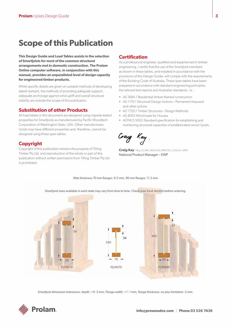
Web thickness 70 mm flanges: 9.5 mm, 90 mm flanges: 11.5 mm
SmartJoist dimension tolerances: depth: +0 -3 mm, Flange width: +/- 1 mm, flange thickness: no plus limitation -2 mm.
SmartJoist sizes available in each state may vary from time to time. Check your local stockist before ordering.
PJ24070 PJ36090PJ30070
240
70
3434
70
300
34
34
90
360

[email protected] | Phone 03 526 7436
4Prolam I-Joists Design Guide
The Strength is in the EngineeringThe Prolam Engineered Timber System is made up of: World class engineered timber products: i. Prolam ii. Prospan iii. Prolam I-Joist iv. Unique Structural Design, Detailing & Online Software
Prolam I-Joists The strength is in the engineering Strong. Stiff. Reliable. Prolam I-Joists are engineered for heavy performance. We start with ultrasonically graded LVL, bonded with exterior adhesive for more load carrying capacity.
The webs are made from stable, strong Oriented Strand Board (OSB) for superior strength and consistent performance. Prolam I-Joists are more uniform than solid sawn joists. They stay straighter and are manufactured with no camber, so there is no chance of crown down or upside down installation. They resist shrinking, twisting, warping and splitting for squeak resistant floors and quality roofs and ceilings.
Holes may be easily cut in the web according to the tables on page 22, allowing ducts and utilities to be run through the joists. Pre-punched 40 mm knockout holes are provided in the web for small diameter services or wiring.
Save time and money Because they weigh less than solid sawn joists, Prolam I-Joists are easier to install, saving construction time and cost. Their greater load carrying capacity allows you to space them further apart, so it takes fewer to build the average floor or roof. And with five (4) depths from 200 to 360 mm, you will never have to compromise your design. So whether your plans call for cantilever beams in balconies, cathedral roofs or high pitched roof slopes, Prolam I-Joists are the perfect choice.
An environmentally sound choice In addition to being cost effective, Prolam I-Joists are also an environmentally sound choice because they are made of a renewable resource – wood. So they are a better choice for building.
Prolam Online SoftwareOur unique Prolam Online, detailing and estimating software offers you unparalleled design and estimating capabilities with engineered timber. You will get accurate designs for a wide variety of applications, printouts and joist layouts.
Limitations of use – Prolam I-Joists Prolam I-Joists are to be used in dry interior environments only, fully enclosed from exposure to exterior moisture. Prolam I-Joists are suitable for subfloor applications provided that the subfloor space is ventilated as per the BCA requirements. This means that Prolam I-Joists must not be exposed to environments where the equilibrium moisture content of the joist will exceed 18%. Prowood will not guarantee Prolam I-Joists that have been left exposed to the weather either prior to or during construction for more than 90 days.
Detailing such as cladding or lining must be used in moisture ladenenvironments (commercial kitchens, bathrooms, wet industrial areas, saunas, swimming pool and spa rooms etc.) and constructed in such a way as to prevent exposure of the Prolam I-Joist to moisture.
Prolam I-Joists may be used in applications which are often exposed externally (gable ends, eaves, floor joists applications in elevated houses, cantilevered joists etc.) but must be sufficiently enclosed with a suitable cladding, lining etc. to completely prevent the exposure of the Prolam I-Joist to moisture.
Product WarrantyProwood guarantees that Prolam I-Joist products have been manufactured to exacting standards and are free from defects in workmanship and materials.
At Prowood, we take great pride in Prolam I-Joist products, so if you bring to our attention problems such as squeaks that you believe are caused by our products, we guarantee that a technical representative will contact you promptly to evaluate the issues and provide advice to help solve the problem.
Providing that any Prolam product is correctly designed, handled and installed, any problem caused by an unlikely defect will promptly be remedied at no cost to you.
WE’RE PROUDLY NEW ZEALAND OWNED & OPERATED
[email protected] | Phone 03 526 7436
5Prolam I-Joists Design Guide
General information about Floor PerformanceThe “feeling” that is identified when a person walks on a floor is very subjective. Some people want to feel a very stiff floor and others want some ”give” so that it softens the footing. When people say the floor “bounces”, it may be vibrating. This sensation is often caused by lack of dead load such as furniture, direct applied ceilings or other materials to absorb or dampen the vibration.
The allowable spans shown in the tables of this manual have been designed to meet the strength and serviceability criteria in AS1684.1. This standard introduced a further serviceability equation into the design of floor joists which checked the deflection caused by a 1.0 kN load applied at mid-span. If the differential deflection of the joist relative to an adjacent joist exceeds 2.0 mm then the span is deemed to be such that the floor performance may be considered too bouncy for service.
Factors that can affect floor dynamic performance• The choice of flooring system • The depth, stiffness and mass of the joists • Spacing of joists • Fixing of sheathing to joists • Stiffness and mass of floor sheathing • Mass and stiffness of ceiling materials • Method of installation • Location and type of internal partitions and furniture.
Factors that can improve floor dynamic performance• Glue-nailed floors will perform better than floors secured by nails alone • Deflection of the sheathing material between joists can be reduced by decreasing the joist spacing or using a thicker and/or stiffer sheathing • Proper installation is essential for dependable performance. Adequate and level support for the joists is necessary, as is correct fastening of the joists and sheathing • The installation of a ceiling to the bottom flange of the joists • Between joist blocking can provide some improvement to floor dynamic performance. It is emphasised that for between joist blocking to be effective, it is important that the blocking is continuous, this being easily achieved by the addition of a continuous bottom strap such as hoop iron strapping which is also attached to the end walls.
If floor dynamic performance is a concern to either the client, designer or contractor, then the above variables can be altered to improve dynamic performance. Some stiff floors with very little dead load may tend to vibrate. This can generally be dampened by directly attaching the ceiling below the underside of the joists. Where there is no lining to the underside of the joists, it is recommended that between joist blocking be utilised to dampen this lightweight floor.
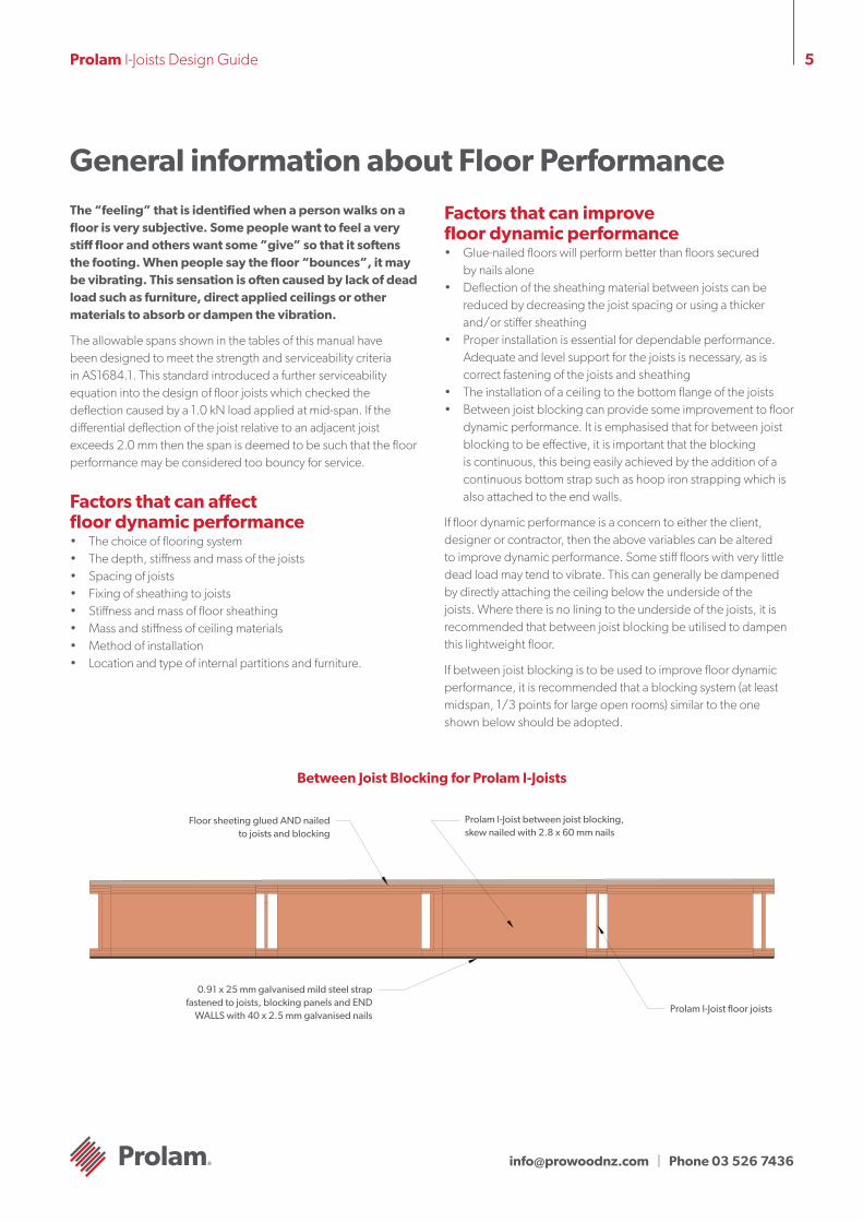
If between joist blocking is to be used to improve floor dynamic performance, it is recommended that a blocking system (at least midspan, 1/3 points for large open rooms) similar to the one shown below should be adopted.
Between Joist Blocking for Prolam I-Joists
Floor sheeting glued AND nailed to joists and blocking
Prolam I-Joist between joist blocking, skew nailed with 2.8 x 60 mm nails
Prolam I-Joist floor joists
0.91 x 25 mm galvanised mild steel strap fastened to joists, blocking panels and END
WALLS with 40 x 2.5 mm galvanised nails
[email protected] | Phone 03 526 7436
6Prolam I-Joists Design Guide
Prolam I-Joist Design/Effective SpanNormal structural analysis uses the centreline representation of the member. The term “span” can be defined in a number of ways and these are defined as follows:
Clear Span: This is the distance between the faces of any support. It is generally the one easiest to measure and read from the drawings.
Nominal span/centre-line span: This is the distance between the centre of the supports. This span is used to determine bending moments and deflections for continuous spanning Prolam I-Joist members.
Design span/Effective span: This is the span used for single span members to determine the bending moment, the slenderness of bending members and the deflections. In AS 1720.1, this is the dimension referred to as “L”, and is defined below.
Design span/Effective span is the distance between:
• The centre of the bearing at each end of a beam where the bearing lengths have NOT been conservatively sized • The centre of notional bearing that have been sized appropriately, where the size of the bearing IS conservative.
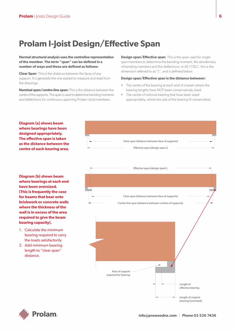
Diagram (a) shows beam where bearings have been designed appropriately. The effective span is taken as the distance between the centre of each bearing area.
Diagram (b) shows beam where bearings at each end have been oversized. (This is frequently the case for beams that bear onto brickwork or concrete walls where the thickness of the wall is in excess of the area required to give the beam bearing capacity).
1. Calculate the minimum bearing required to carry the loads satisfactorily 2. Add minimum bearing length to “clear span” distance.
Clear span (distance between face of supports)
Effective span (design span L)
Effective span (design span) L
Clear span (distance between face of supports)
Centre-line span (distance between centres of supports)
Area of support required for bearing
Length of effective bearing
Length of original bearing (oversized)
[email protected] | Phone 03 526 7436
7Prolam I-Joists Design Guide
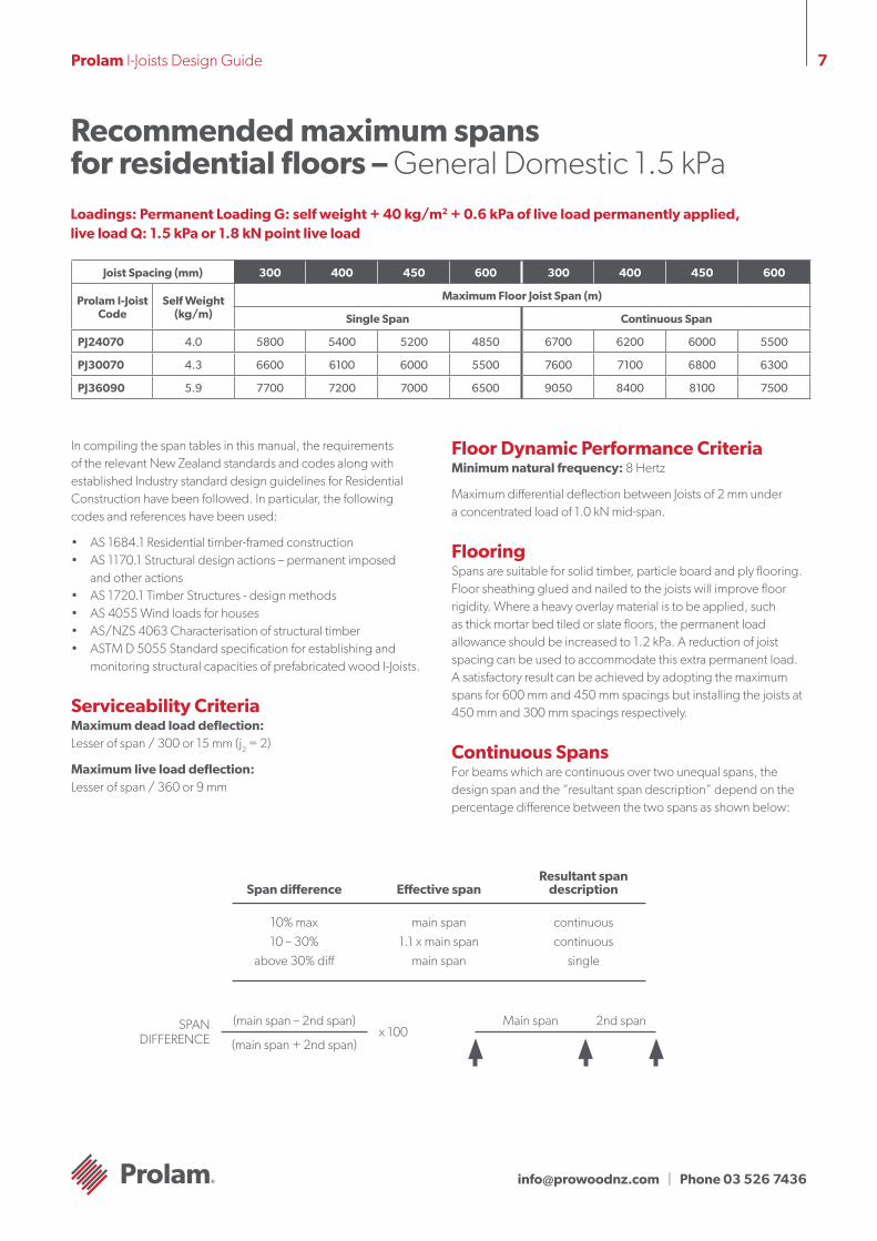
Recommended maximum spans for residential floors – General Domestic 1.5 kPaLoadings: Permanent Loading G: self weight + 40 kg/m2 + 0.6 kPa of live load permanently applied, live load Q: 1.5 kPa or 1.8 kN point live load
Joist Spacing (mm) 300 400 450 600 300 400 450 600
Prolam I-Joist Code
Self Weight (kg/m)
Maximum Floor Joist Span (m)
Single Span Continuous Span
PJ24070 4.0 5800 5400 5200 4850 6700 6200 6000 5500
PJ30070 4.3 6600 6100 6000 5500 7600 7100 6800 6300
PJ36090 5.9 7700 7200 7000 6500 9050 8400 8100 7500
In compiling the span tables in this manual, the requirements of the relevant New Zealand standards and codes along with established Industry standard design guidelines for Residential Construction have been followed. In particular, the following codes and references have been used:
• AS 1684.1 Residential timber-framed construction • AS 1170.1 Structural design actions – permanent imposed and other actions • AS 1720.1 Timber Structures - design methods • AS 4055 Wind loads for houses • AS/NZS 4063 Characterisation of structural timber • ASTM D 5055 Standard specification for establishing and monitoring structural capacities of prefabricated wood I-Joists.
Serviceability Criteria Maximum dead load deflection:Lesser of span / 300 or 15 mm (j2 = 2)
Maximum live load deflection:Lesser of span / 360 or 9 mm
Floor Dynamic Performance Criteria Minimum natural frequency: 8 Hertz
Maximum differential deflection between Joists of 2 mm under a concentrated load of 1.0 kN mid-span.
Flooring Spans are suitable for solid timber, particle board and ply flooring. Floor sheathing glued and nailed to the joists will improve floor rigidity. Where a heavy overlay material is to be applied, such as thick mortar bed tiled or slate floors, the permanent load allowance should be increased to 1.2 kPa. A reduction of joist spacing can be used to accommodate this extra permanent load. A satisfactory result can be achieved by adopting the maximum spans for 600 mm and 450 mm spacings but installing the joists at 450 mm and 300 mm spacings respectively.
Continuous Spans For beams which are continuous over two unequal spans, the design span and the “resultant span description” depend on the percentage difference between the two spans as shown below:
Effective spanResultant span
descriptionSpan difference
10% max10 – 30%
above 30% diff
main span1.1 x main span
main span
continuouscontinuous
single
(main span – 2nd span)
(main span + 2nd span)
SPAN DIFFERENCE x 100
Main span 2nd span
[email protected] | Phone 03 526 7436
8Prolam I-Joists Design Guide
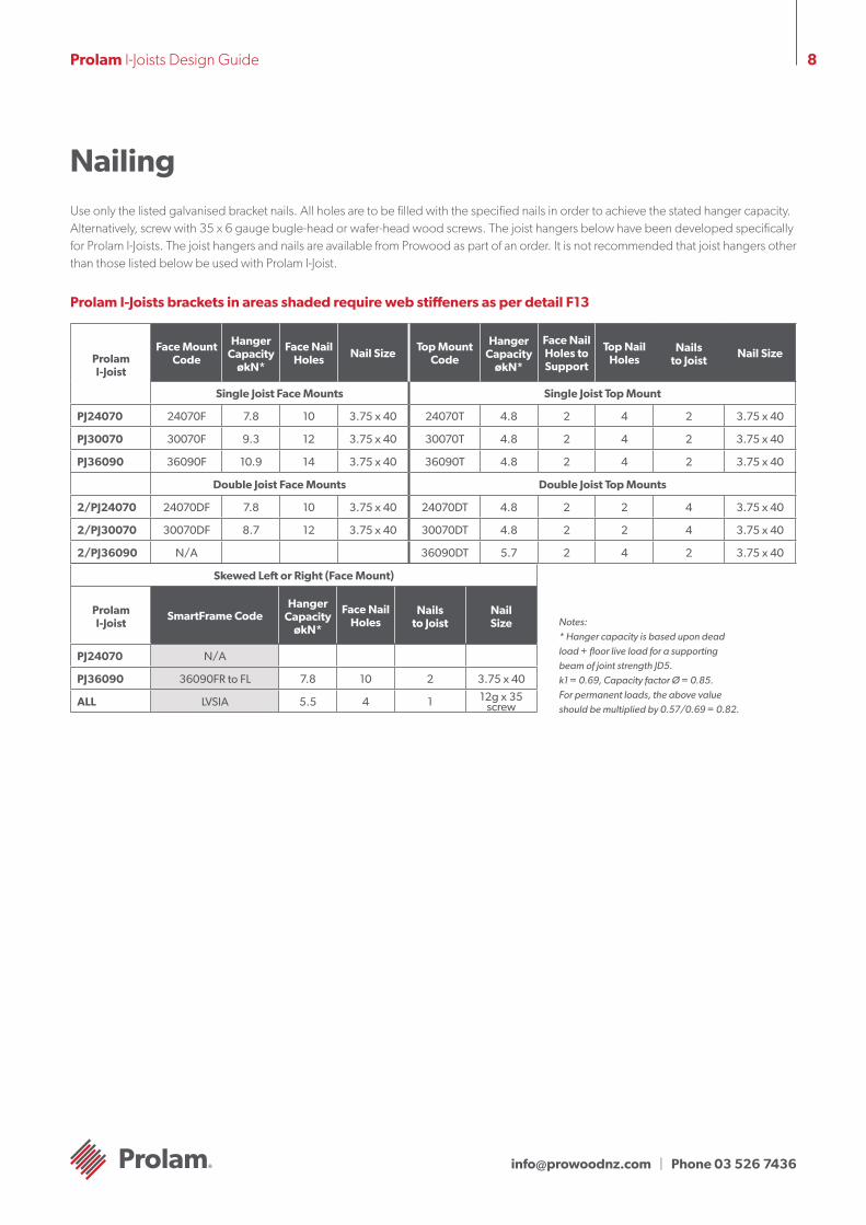
NailingUse only the listed galvanised bracket nails. All holes are to be filled with the specified nails in order to achieve the stated hanger capacity. Alternatively, screw with 35 x 6 gauge bugle-head or wafer-head wood screws. The joist hangers below have been developed specifically for Prolam I-Joists. The joist hangers and nails are available from Prowood as part of an order. It is not recommended that joist hangers other than those listed below be used with Prolam I-Joist.
Prolam I-Joists brackets in areas shaded require web stiffeners as per detail F13
Prolam I-Joist
Face Mount Code
Hanger Capacity
økN*
Face Nail Holes Nail Size Top Mount
Code
Hanger Capacity
økN*
Face Nail Holes to Support
Top Nail Holes
Nails to Joist
Nail Size
Single Joist Face Mounts Single Joist Top Mount
PJ24070 24070F 7.8 10 3.75 x 40 24070T 4.8 2 4 2 3.75 x 40
PJ30070 30070F 9.3 12 3.75 x 40 30070T 4.8 2 4 2 3.75 x 40
PJ36090 36090F 10.9 14 3.75 x 40 36090T 4.8 2 4 2 3.75 x 40
Double Joist Face Mounts Double Joist Top Mounts
2/PJ24070 24070DF 7.8 10 3.75 x 40 24070DT 4.8 2 2 4 3.75 x 40
2/PJ30070 30070DF 8.7 12 3.75 x 40 30070DT 4.8 2 2 4 3.75 x 40
2/PJ36090 N/A 36090DT 5.7 2 4 2 3.75 x 40
Skewed Left or Right (Face Mount)
Prolam I-Joist
SmartFrame CodeHanger
Capacity økN*
Face Nail Holes
Nails to Joist
Nail Size
PJ24070 N/A
PJ36090 36090FR to FL 7.8 10 2 3.75 x 40
ALL LVSIA 5.5 4 1 12g x 35 screw
Notes:* Hanger capacity is based upon dead load + floor live load for a supporting beam of joint strength JD5.k1 = 0.69, Capacity factor Ø = 0.85. For permanent loads, the above value should be multiplied by 0.57/0.69 = 0.82.

[email protected] | Phone 03 526 7436
9Prolam I-Joists Design Guide
Safety Warning
Handling & Storage of Prolam I-Joists
Do not allow workers or loads on Prolam I-Joists until all blocking, hangers, rim joists, nailing and temporary bracing are installed as specified below. Serious accidents or injury can result from failure to follow these guidelines.
Accidents can be avoided under normal conditions by following these guidelines:
1. Brace each joist as it is erected. Joists must be nailed to supports and all hangers, blocking, rim joists. X - bridging at supports must be completely installed and properly nailed. (see general notes and details).2. Brace the ends of cantilevers (overhangs) with closure panels, rim joist or x - bridging (see general notes and details).3. Lateral brace the top flange of each joist, to prevent sideways buckling or rollover which may occur under light construction loads, such as a worker and/or a layer of un-nailed sheathing. Fully installed permanent sheathing or temporary struts to the top flange of each joist (see
‘Typical SmartJoist floor framing’) can accomplish lateral bracing. Temporary struts must be nailed to a lateral restraint at the end of bay such as a braced wall or temporary (or permanent) sheathing nailed to the first 1200 mm of the joist at the end of the bay (see ‘Typical floor or roof framing’).4. Permanent sheathing must be completely installed and properly nailed before additional loads can be placed on the system.5. The integrity and safe use of these products can be seriously impaired if they are damaged. Do not install any damaged products. Contact your Prowood representative on 0508 776 526 if any product damage is noted.
• Store Prolam I-Joists flat on a hard, dry surface
• If surface isn’t paved, the ground should be covered with a polythene film
• Keep covered with waterproof material that allows bundles to “breathe”
• Use bearers (bolsters) between the ground and the first bundle (4 metre max spacing)
• Use 100 x 50 timber flat between bundles at same spacing as bolsters
• Take great care to rewrap remaining material after opening bundles
• Wood “grows” in thickness and depth when allowed to get wet....KEEP DRY!
• Wood with high MC has short term reduction in Characteristic Strengths …. KEEP DRY!
• Under NO circumstances are stored Prolam I-Joists to be in contact with the ground.
Prolam I-Joists should be stacked in the upright position to avoid any damage
Use bearers to keep stacked material away from damp surfaces. Align bearer vertically.
Bearers at a maximum of 4000 mm centres

[email protected] | Phone 03 526 7436
10Prolam I-Joists Design Guide
Durability and Exposure to MoistureProlam I-Joists are manufactured with Douglas Fir (Oregon)flanges with OSB webs, both having a durability rating of class 4, which is the same rating as some Ash type Eucalypts.
Moisture effects on Prolam I-JoistsProlam I-Joist is supplied WITHOUT any short term construction sealer, but once framed into a structure may be exposed to the weather for a limited time (not greater than 3 months) without negative affect, BUT, it may exhibit some effects of this exposure.
The wood fibre in Prolam I-Joists, like all wood products, is hygroscopic, which means it has an affinity for water. The wood fibre in Prolam I-Joist will readily take up and release moisture in response to changes in the local environment. Moisture exposure will lead to dimensional change. While the products will withstand normal exposure, excessive exposure during distribution, storage or construction may lead to dimensional changes that affect serviceability. These changes include twisting, bowing or expansion to dimensions to beyond the specified tolerance of the product in the “as-manufactured” condition.
As an organic material, mold and mildew may grow on untreated wood products if moisture is present. Prolonged periods of high moisture may also support the growth of wood decay fungi, which is another reason to follow proper methods of storage and handling of Prolam I-Joists. The table below shows the moisture content of Prolam I-Joists as a function of humidity.
Wetting during construction may lead to temporary elevated moisture content and dimensional changes. Once covered, the Prolam I-Joist will ultimately dry and re-equilibrate to the ambient humidity conditions, but some expansion or swelling may remain after drying.
Moisture content of wood products %1
Relative Humidity% LVL Flange MC OSB web
10 1.2 0.8
20 2.8 1.0
30 4.6 2.0
40 5.8 3.6
50 7.0 5.2
60 8.4 6.3
70 11.1 8.9
80 15.3 13.1
90 19.4 17.2
1 Approximate moisture content at 21°
Prolam I-Joists General Notes1. Except where otherwise noted, 30 mm minimum bearing is
required at joist ends and 42 mm minimum bearing is required at intermediate supports.
2. Nail joists at each bearing with 2 of 3.15ø x 65 nails, using one each side placed 30 mm from the end to avoid splitting.
3. Prolam I-Joist blocking or Prorim - face nail to bearing plate with 3.15ø x 65 nails at 150 mm centres. Nail rim joist to the end of the top and bottom flange of each Prolam I-Joist with 1 3.15ø x 65 nail, use 1 3.75 x 75 nail top and bottom with joists with 58, 70 or 90mm wide flanges.
4. 4.25 mm Prorim - toe nail to bearing plate with 3.15ø x 65 nails at 150 centres or 4.5ø x 75 nails at 300 centres. Nail rim to the end of the top and bottom flanges of each Prolam I-Joist with 1 3.15ø x 65 nails.
5. Sheathing nailing to top flange (Joists must be fully braced before sheathing is nailed)
- Space 2.8ø x 65 and 3.15ø x 65 nails no closer than 50 mm per row.
- Space 3.75 x 75 nails no closer than 75 mm. Maximum nail spacing: 300 mm
Start toe nail approximately 2/3 up the side of the flange.
Nails should be as far as practical from the end of the joist.
DO NOT start toe nail into the corner of the flange or the top of the flange.
MAXIMUM nail diameter 3.15mm
[email protected] | Phone 03 526 7436
11Prolam I-Joists Design Guide
Blocking and Lateral Restraint General Notes
Prolam I-Joists designed and constructed as per this Design Guide do not require mid-span blocking. The exception to this is for lightweight subfloors where there is no lining to the underside of the joists. For more information on this topic, see page 3 ‘About Floor Performance’.
Blocking within a structure falls within two (2) quite distinct stages: Temporary or during construction blocking to prevent roll over of joists before the installation of floor sheeting. Permanent blocking to provide resistance to racking loads through the floor diaphragm, transfer of vertical wall loads and to provide torsional resistance to the end of the joist.
The provision contained within AS1684 Residential timberframed construction code dealing with blocking for deep joists, is “during construction” or “temporary” blocking, designed only to prevent the roll over of the deep joists prior to the floor sheeting being attached. This level of blocking can form a part of any overall blocking system, but was never intended to provide the total amount of racking resistance or vertical load transfer requirements within this floor diaphragm.
The lateral bracing requirements of the structure, unless there is full blocking of exterior walls, must be calculated in each individual case. Advice on this matter is obtainable from AS1684 Residential timber-framed construction code.
1.0 Joists bearing onto external walls 1.1 Loads at Joist/support connection The ends of floor joists that bear onto a support experience external loads other than the floor dead and live loads, as shown. Any I-Joist, with it’s small cross sectional area, needs to have its end bearing capacity considered as part of the design process.
Further, as a holistic approach to the consideration of the lateral stability of the complete structure, it is necessary to consider the availability of racking and shear resistance through the floor diaphragm.
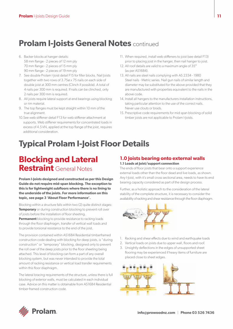
1. Racking and shear effects due to wind and earthquake loads2. Vertical loads on joists due to upper wall, floors and roof.3. Unsightly deflections in the edges of unsupported sheet
flooring may be experienced if heavy items of furniture are placed close to sheet edges.
Prolam I-Joists General Notes continued
Typical Prolam I-Joist Floor Details
6. Backer blocks at hanger details: 58 mm flange - 2 pieces of 12 mm ply 70 mm flange - 2 pieces of 15 mm ply 90 mm flange - 2 pieces of 19 mm ply
7. See double Prolam I-Joist detail F15 for filler blocks. Nail Joists together with two rows of 3.75ø x 75 nails on each side of double joist at 300 mm centres (Clinch if possible). A total of 4 nails per 300 mm is required. If nails can be clinched, only 2 nails per 300 mm is required.
8. All joists require lateral support at end bearings using blocking or rim material.
9. The top flanges must be kept straight within 10 mm of the true alignment.
10. See web stiffener detail F13 for web stiffener attachment at supports. Web stiffener requirements for concentrated loads in excess of 4.5 kN, applied at the top flange of the joist, requires additional consideration.
11. When required, install web stiffeners to joist (see detail F13)prior to placing joist in the hanger, then nail hanger to joist.
12. All roof details are valid to a maximum angle of 35° (as per AS1684).
13. All nails are steel nails complying with AS 2334 - 1980 Steel nails - Metric series. Nail gun nails of similar length and diameter may be substituted for the above provided that they are manufactured with properties equivalent to the nails in the above code.
14. Install all hangers to the manufacturers installation instructions, taking particular attention to the use of the correct nails. Never use clouts or brads.
15. Prescriptive code requirements for mid span blocking of solid timber joists are not applicable to Prolam I-Joists.
[email protected] | Phone 03 526 7436
12Prolam I-Joists Design Guide
1.2 Stages of Blocking/Bracing 1.2.1 Temporary (during construction) end blocking Temporary or during construction blocking of the ends of joists over external wall must comply with the requirements as shown in the “Safety Warning” on page 7 and as shown in the “Typical Prolam I-Joist floor framing” diagram on page 12.
This is summarised as: • Temporary struts, fastened to top of Prolam I-Joist, connected
back to braced supports.• Temporary floor sheeting nailed to the first 1200 mm of joists at
the end of the bay, in combination with struts, if no connection to a braced wall can be made.
1.2.2 Permanent End Blocking/Bracing Permanent blocking (bracing) to be effective in providing adequate transfer of racking and shear loads through the floor diaphragm must comply with the details as shown in “Typical Prolam I-Joist framing” diagram on page 12. In essence, fully block the ends of all joists at their bearing point on external walls, as per one of the options shown indetails F1- F4.
This permanent blocking/bracing provides:
1. A satisfactory mechanism to transfer racking loads through the floor diaphragm.
2. Vertical load transfer independent of the floor joist.3. Support to the end of the floor sheeting (Platform floors only).
Heavily loaded furniture legs have been known to cause large deflections and even failures at the edges of sheet flooring.
4 Torsional restraint to the end of floor joists, improving the joists structural performance.
2.0 Interior Supports 2.1 Ends of simple spans Where Prolam I-Joists are discontinuous over interior supports, install the temporary strut bracing as per “Safety Warning” on page 7.
2.2 Continuous spans Continuous joists over internal supports do not require blocking, other than the temporary top flange struts as shown in the “Safety Warning” on page 7, except in the following circumstances:
• Load bearing walls bear onto the joists at their support. (Details F7 or F8 apply)
• Shear resistance is required in internal walls (This is a function of shear resistance, and is not related to the structural adequacy of the joist itself).
3.0 Blocking and Wall Plates Wall plates in the frame are required to transfer vertical loads into the support structure below. These wall plates may be supported at 450 or 600 mm ctrs, thus acting as a beam between supports, bending about its weaker axis.
When concentrated loads act at the centre of this wall plate, the bending and deflection effects can be quite significant.
The full blocking of external and load bearing walls, as shown in details F1-F4, can act as a beam transferring these loads to the support structure below, thus reducing the beam effect of the wall plates.
Unless there is a requirement for double wall plates for a reason other than the beam effect between supports, walls blocked as per detail F1-F4 and general notes #2, #3, and #4 provide sufficient.
Typical Prolam I-Joist Floor Details continued
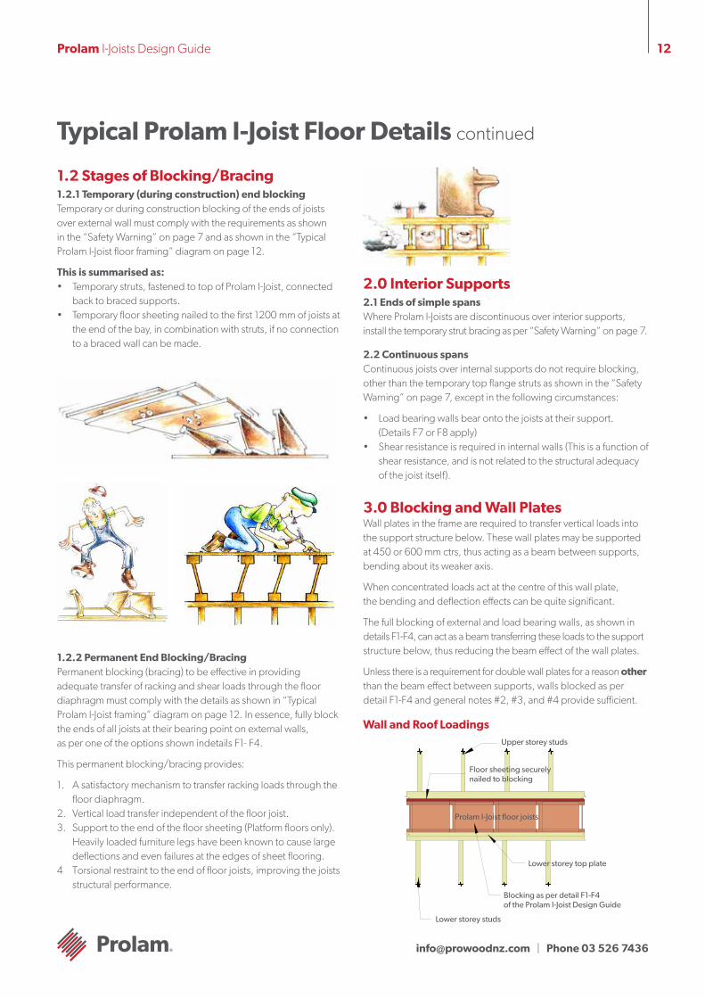
Prolam I-Joist floor joists
Upper storey studs
Lower storey top plate
Blocking as per detail F1-F4 of the Prolam I-Joist Design Guide
Lower storey studs
Floor sheeting securely nailed to blocking
Wall and Roof Loadings

[email protected] | Phone 03 526 7436
13Prolam I-Joists Design Guide
Field Repairs to Damaged Prolam I-Joists
Note: Prolam I-Joists are sophisticated Engineered Timber products, and must be treated accordingly. Damage to key components, while affecting only a small percentage of the cross section may be sufficient to render the Prolam I-Joist unsuitable for the purpose.
Don’t make holes with hammer other than pre-punched knockouts
Do not cut or notch flanges Do not over-cut holes in web
Don’t hammer on flanges and damage joint
Flange Damage • Flange damage becomes more critical the nearer it is to mid-
span or an interior support. Flange damage is less critical in close proximity to an end support.
• How much flange damage is acceptable? A rule of thumb is “If you have to ask, it’s too much”. A saw kerf that knicks the corner of a flange on one lightly-loaded joist could well be acceptable.
• A joist with unacceptable flange damage cannot be repaired, rather a new joist must be added to take it’s place. The damaged joist does not have to be removed. Consult Prolam I-Joist tables to find an acceptable new joist that is shallower than the damaged joist so installation is easier. Consider double and triple joists. If the damaged joist is multi-span, the new joist only needs to go across the span(s) where the damage occurs.
• A single damaged joist can sometimes be trimmed off of adjacent undamaged joists.
Web Damage • Web damage becomes more critical the nearer a support.
Web damage is less critical near mid-span.
• Web holes can be too big to repair. A flange-to-flange rectangular hole longer than 450 mm located at midspan probably warrants a new joist. A 150 mm round hole located right by a support probably warrants a new joist. Consult Prolam I-Joist tables to find an acceptable new joist that is shallower than the damaged joist so installation is easier. Consider double and triple joists. If the damaged joist is multi-span, the new joist only needs to go across the span(s) where the damage occurs.
• A single damaged joist can sometimes be trimmed off of adjacent undamaged joists (run a calculation within the Prolam software).
• Damage that could be confidently repaired in a single, isolated joist, might be judged too severe to repair if several, adjacent joists are involved.
• If several small holes violate the 2x diameter proximity rule, but would fit inside a single acceptable hole, then the group of small holes is OK.
• Hole repairs generally require a reinforcement that covers the full depth of the web and extends at least 300 mm past each side of the hole.
[email protected] | Phone 03 526 7436
14Prolam I-Joists Design Guide
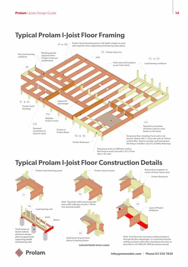
Typical Prolam I-Joist Floor Framing
Standard connection of Prolam I-Joist to solid timber or LVL beam
Temporary floor sheeting if end wall is not braced. Attach with 3.15mm dia nails at 150mm centres Max. Keep in position until permanent sheeting is installed. (see #2 of Safety Warning).
F11
Temporary struts at 2400mm centres. Nail struts to each joist with 2 of 3.15mm diam x 65 nails
F3 F4&
Prolam Rimboard
Prolam or Prolam Beam
Multiple Prolam I-Joists
F15
Standard connection of I-Joist to I-Joist
F12
F1 F5&
Load bearing cantilever
C1 C2or
Hole sizes and locations as per hole charts
Approved joist hanger
joist
F2 Prolam I-Joist rim
Prolam I-Joist blocking panel or full depth cripple on each side required when supporting loud bearing walls aboveF7 F8or
Blocking panels required when Prolam I-Joists are cantilevered
Non load-bearing cantilever
F9
Typical Prolam I-Joist Floor Construction DetailsProlam I-Joist blocking panel
Load-bearing wall
JoistsBearer
Small section of bearer material placed on stumps/piers to support joists supporting parallel load-bearing walls
F4
F1
Prolam I-Joist rim joist
F2
F5
Solid block all posts from above to bearing below
Note: Top plate width must be greater than width of flange rim joist +30mm (min bearing length)
Butt sections together at centre of lower storey stud
Prolam Rimboard
Layer of Prolam RimBoard
F3
Note: To achieve the necessary racking resistance through the floor diaphragm, it is important that the nailing provisions of the floor sheeting to the joists as described in AS 1684 (AS 1869 for particle board).CONCENTRATED ROOF LOADS
Prolam I-Joist blocking
[email protected] | Phone 03 526 7436
15Prolam I-Joists Design Guide
Typical SmartJoist floor construction details continued
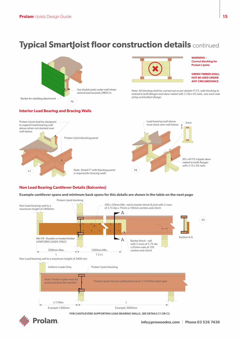
Backer for cladding attachment
Use double joists under wall where vertical load exceeds 29KN/m
F6
Note: All blocking shall be carried out as per details F1-F3, with blocking to extend to both flanges and skew nailed with 3.15ø x 65 nails, one each side of top and bottom flange
WARNING - Correct blocking for Prolam I-Joists
GREEN TIMBER SHALL NOT BE USED UNDER ANY CIRCUMSTANCE
Interior Load Bearing and Bracing Walls
Prolam I-Joist shall be designed to support load bearing wall above when not stacked over wall below
Prolam I-Joist blocking panel
F7 Note: Detail F7 with blocking panel is required for bracing walls
F8
2mm
90 x 45 F5 cripple skew nailed to both flanges with 3.15 x 65 nails
Load bearing wall above must stack over wall below
Non Load Bearing Cantilever Details (Balconies)
Example cantilever spans and minimum back spans for this details are shown in the table on the next page
200 x 50mm Min. nail to backer block & joist with 2 rows of 3.15 dia x 75mm a 150mm centres and clinch
A
A
F9
Section A-ABacker block - nail with 2 rows of 3.75 dia x 65mm nails at 150 centres and clinch
Non load-bearing wall to a maximum height of 2400mm
Prolam I-Joist blocking
Min F8 - Durable or treated timber (UNIFORM LOADS ONLY)
1200mm Max. 1200mm Min.
L 1.5 x L
Uniform Loads Only Prolam I-Joist blocking
Prolam I-Joist may be cantilevered up to 1/3 of their back span
L/3 Max.
Example 1200mm
L
Example 3600mm
Note: Prolam I-Joists must be protected from the weather
FOR CANTILEVERS SUPPORTING LOAD BEARING WALLS, SEE DETAILS C1 OR C2
Non Load bearing wall to a maximum height of 2400 mm
[email protected] | Phone 03 526 7436
16Prolam I-Joists Design Guide
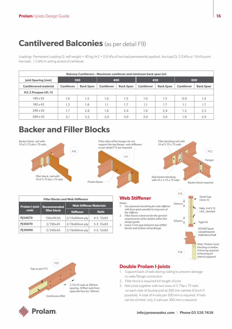
Backer and Filler Blocks
Cantilvered Balconies (as per detail F9)
Balcony Cantilevers - Maximum cantilever and minimum back span (m)
Joist Spacing (mm) 300 400 450 600
Cantilevered material Cantilever Back Span Cantilever Back Span Cantilever Back Span Cantilever Back Span
H3.2 Prospan LVL 15
140 x 42 1.0 1.5 1.0 1.5 1.0 1.5 0.9 1.4
190 x 42 1.2 1.8 1.1 1.7 1.1 1.7 1.1 1.7
240 x 42 1.7 2.6 1.6 2.4 1.6 2.4 1.5 2.3
290 x 42 2.1 3.2 2.0 3.0 2.0 3.0 1.9 2.9
Loadings: Permanent Loading G: self weight + 40 kg/m2 + 0.6 kPa of live load permanently applied, live load Q: 2.0 kPa or 1.8 kN point live load , 1.5 kN/m acting at end of cantilever.
Backer block, nail with 10 of 3.75 dia x 75 nails
Filler block, nail with 10 of 3.75 dia x 75 nails
F10
If the sides of the hanger do not support the top flange, web stiffeners as per detail F13 are required
F11
Prolam Beam
Filler blocking nail with 10 of 3.75 x 75 nails
Nail backer blocking with 10 x 3.75 x 75 nails
Backer block required
Hanger
F12
Filler Blocks and Web Stiffeners
Prolam I-Joist code
Recommended filler block
Web Stiffener Materials
Stiffener Nails
PJ24070 150x58 LVL 2/15x60mm ply 4-3. 15x65
PJ30070 2/190x45 2/19x60mm ply 5-3. 15x65
PJ36090 2/240x45 2/19x60mm ply 5-3. 15x65
Web StiffenerNotes:1. Use plywood sheathing for web stiffener
with face grain parallel to long axis of the stiffener.
2. Filler blocks noted are for the general requirements of the details within this design guide.
3. Leave 3 mm gap between top of filler blocks and bottom of top flange.
Double Prolam I-Joists 1. Support back of web during nailing to prevent damage
to web/flange connection2. Filler block is required full length of joist3. Nail Joists together with two rows of 3.75ø x 75 nails
on each side of double joist at 300 mm centres (Clinch if possible). A total of 4 nails per 300 mm is required. If nails can be clichéd, only 2 nails per 300 mm is required.
F13
F14
50mm±
Small Gap (3mm ±)
Nails, 4 of 3.15 x 65 , clinched
50mm± Tight Fit
Note: Prolam I-joist blocking or timber X-bracing required at bearing for lateral suppport
DO NOT bevel cut joist beyond inside face of wall
Gap as per F13
Continuous filler
3.75x75 nails at 300mm spacing. (Offset nails from opposite face by 150mm)
F15
[email protected] | Phone 03 526 7436
17Prolam I-Joists Design Guide
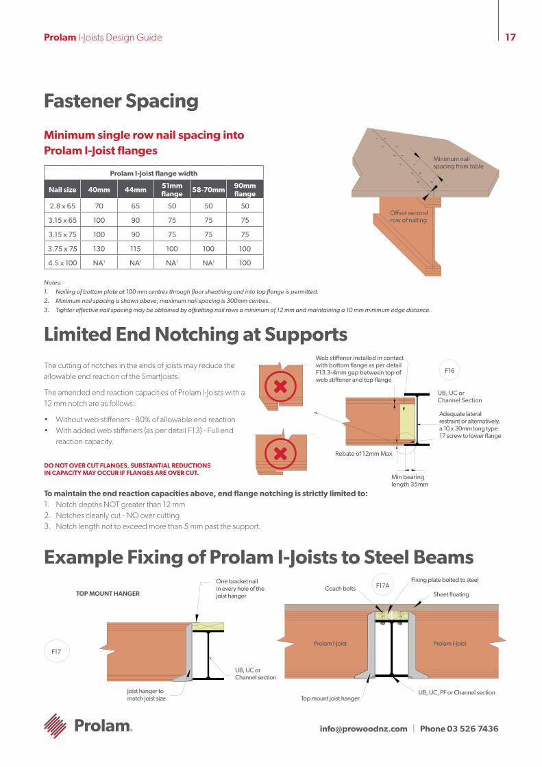
Fastener Spacing
Prolam I-Joist flange width
Nail size 40mm 44mm 51mm flange 58-70mm 90mm
flange
2.8 x 65 70 65 50 50 50
3.15 x 65 100 90 75 75 75
3.15 x 75 100 90 75 75 75
3.75 x 75 130 115 100 100 100
4.5 x 100 NA1 NA1 NA1 NA1 100
Minimum single row nail spacing into Prolam I-Joist flanges
Notes:1. Nailing of bottom plate at 100 mm centres through floor sheathing and into top flange is permitted.2. Minimum nail spacing is shown above, maximum nail spacing is 300mm centres.3. Tighter effective nail spacing may be obtained by offsetting nail rows a minimum of 12 mm and maintaining a 10 mm minimum edge distance.
Minimum nail spacing from table
Offset second row of nailing
Limited End Notching at SupportsThe cutting of notches in the ends of joists may reduce the allowable end reaction of the SmartJoists.
The amended end reaction capacities of Prolam I-Joists with a 12 mm notch are as follows:
• Without web stiffeners - 80% of allowable end reaction• With added web stiffeners (as per detail F13) - Full end
reaction capacity.
DO NOT OVER CUT FLANGES. SUBSTANTIAL REDUCTIONS IN CAPACITY MAY OCCUR IF FLANGES ARE OVER CUT.
F16
Web stiffener installed in contact with bottom flange as per detail F13 3-4mm gap between top of web stiffener and top flange
Rebate of 12mm Max
Min bearing length 35mm
UB, UC or Channel Section
Adequate lateral restraint or alternatively, a 10 x 30mm long type 17 screw to lower flange
To maintain the end reaction capacities above, end flange notching is strictly limited to:1. Notch depths NOT greater than 12 mm2. Notches cleanly cut - NO over cutting3. Notch length not to exceed more than 5 mm past the support.
Example Fixing of Prolam I-Joists to Steel Beams
Sheet floating
Prolam I-JoistProlam I-Joist
UB, UC, PF or Channel section
Fixing plate bolted to steelCoach bolts
Top mount joist hanger
F17AOne bracket nail in every hole of the joist hanger
F17
UB, UC or Channel section
Joist hanger to match joist size
TOP MOUNT HANGER
[email protected] | Phone 03 526 7436
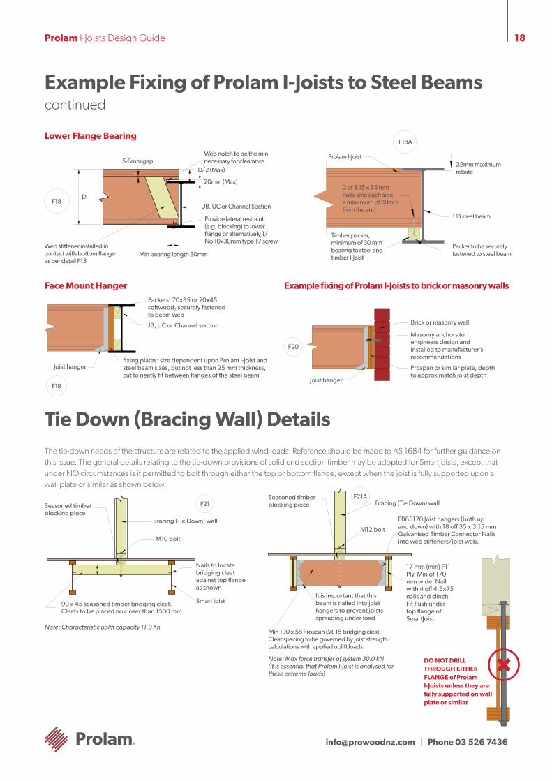
18Prolam I-Joists Design Guide
Seasoned timber blocking piece
Example Fixing of Prolam I-Joists to Steel Beams continued
Lower Flange Bearing
Web notch to be the min necessary for clearance
D/2 (Max)
20mm (Max)
UB, UC or Channel Section
Provide lateral restraint (e.g. blocking) to lower flange or alternatively 1/ No 10x30mm type 17 screw
Min bearing length 30mmWeb stiffener installed in contact with bottom flange as per detail F13
5-6mm gap
DF18
F18A
Prolam I-Joist22mm maximum rebate
UB steel beam
Packer to be securely fastened to steel beam
2 of 3.15 x 65 mm nails, one each side, a minumum of 30mm from the end
Timber packer, minimum of 30 mm bearing to steel and timber I-Joist
Face Mount Hanger Example fixing of Prolam I-Joists to brick or masonry walls
F19
Packers: 70x35 or 70x45 softwood, securely fastened to beam web
UB, UC or Channel section
fixing plates: size dependent upon Prolam I-Joist and steel beam sizes, but not less than 25 mm thickness, cut to neatly fit between flanges of the steel beam
Joist hanger
F20
Masonry anchors to engineers design and installed to manufacturer’s recommendations
Prospan or similar plate, depth to approx match joist depth
Brick or masonry wall
Joist hanger
Tie Down (Bracing Wall) DetailsThe tie-down needs of the structure are related to the applied wind loads. Reference should be made to AS 1684 for further guidance on this issue. The general details relating to the tie-down provisions of solid end section timber may be adopted for SmartJoists, except that under NO circumstances is it permitted to bolt through either the top or bottom flange, except when the joist is fully supported upon a wall plate or similar as shown below.
F21Seasoned timber blocking piece
Bracing (Tie Down) wall
M10 bolt
Nails to locate bridging cleat against top flange as shown
Smart Joist90 x 45 seasoned timber bridging cleat. Cleats to be placed no closer than 1500 mm.
F21ABracing (Tie Down) wall
M12 bolt
It is important that this beam is nailed into joist hangers to prevent joists spreading under load
FB65170 Joist hangers (both up and down) with 18 off 35 x 3.15 mm Galvanised Timber Connector Nails into web stiffeners/joist web.
Min 190 x 58 Prospan LVL 15 bridging cleat. Cleat spacing to be governed by Joist strength calculations with applied uplift loads.
17 mm (min) F11 Ply, Min of 170 mm wide. Nail with 4 off 4.5x75 nails and clinch. Fit flush under top flange of SmartJoist.
Note: Characteristic uplift capacity 11.9 Kn
Note: Max force transfer of system 30.0 kN (It is essential that Prolam I-Joist is analysed for these extreme loads)
DO NOT DRILL THROUGH EITHER FLANGE of Prolam I-Joists unless they are fully supported on wall plate or similar
[email protected] | Phone 03 526 7436
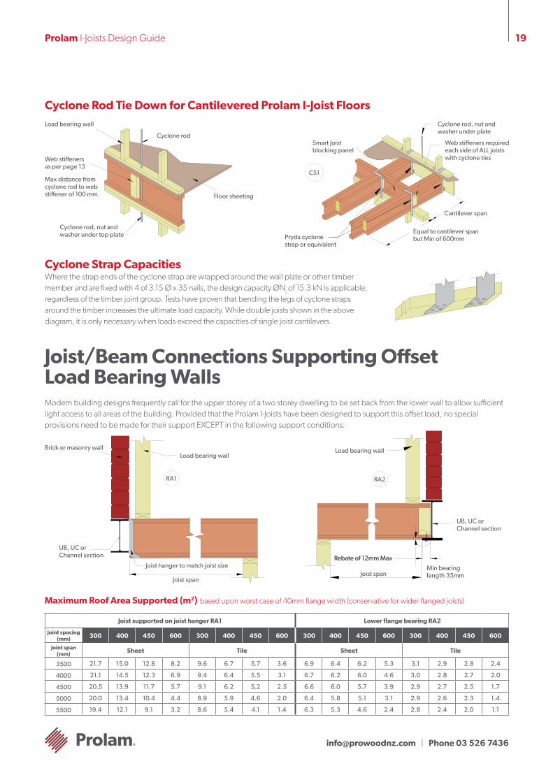
19Prolam I-Joists Design Guide
UB, UC or Channel section
Cyclone Rod Tie Down for Cantilevered Prolam I-Joist FloorsLoad bearing wall
Cyclone rod
Floor sheeting
Cyclone rod, nut and washer under top plate
Web stiffeners as per page 13
Max distance from cyclone rod to web stiffener of 100 mm.
CS1
Cyclone rod, nut and washer under plate
Web stiffeners required each side of ALL joists with cyclone ties
Cantilever span
Equal to cantilever span but Min of 600mmPryda cyclone
strap or equivalent
Smart Joist blocking panel
Cyclone Strap CapacitiesWhere the strap ends of the cyclone strap are wrapped around the wall plate or other timber member and are fixed with 4 of 3.15 Ø x 35 nails, the design capacity ØNj of 15.3 kN is applicable, regardless of the timber joint group. Tests have proven that bending the legs of cyclone straps around the timber increases the ultimate load capacity. While double joists shown in the above diagram, it is only necessary when loads exceed the capacities of single joist cantilevers.
Joist/Beam Connections Supporting Offset Load Bearing WallsModern building designs frequently call for the upper storey of a two storey dwelling to be set back from the lower wall to allow sufficient light access to all areas of the building. Provided that the Prolam I-Joists have been designed to support this offset load, no special provisions need to be made for their support EXCEPT in the following support conditions:
Joist supported on joist hanger RA1 Lower flange bearing RA2
Joint spacing (mm) 300 400 450 600 300 400 450 600 300 400 450 600 300 400 450 600
Joint span (mm)
Sheet Tile Sheet Tile
3500 21.7 15.0 12.8 8.2 9.6 6.7 5.7 3.6 6.9 6.4 6.2 5.3 3.1 2.9 2.8 2.4
4000 21.1 14.5 12.3 6.9 9.4 6.4 5.5 3.1 6.7 6.2 6.0 4.6 3.0 2.8 2.7 2.0
4500 20.5 13.9 11.7 5.7 9.1 6.2 5.2 2.5 6.6 6.0 5.7 3.9 2.9 2.7 2.5 1.7
5000 20.0 13.4 10.4 4.4 8.9 5.9 4.6 2.0 6.4 5.8 5.1 3.1 2.9 2.6 2.3 1.4
5500 19.4 12.1 9.1 3.2 8.6 5.4 4.1 1.4 6.3 5.3 4.6 2.4 2.8 2.4 2.0 1.1
Maximum Roof Area Supported (m2) based upon worst case of 40mm flange width (conservative for wider flanged joists)
Load bearing wall
UB, UC or Channel section
Min bearing length 35mm
Rebate of 12mm Max
Joist span
RA2
Load bearing wallBrick or masonry wall
RA1
Rebate of 12mm MaxJoist hanger to match joist size
Joist span
[email protected] | Phone 03 526 7436
20Prolam I-Joists Design Guide
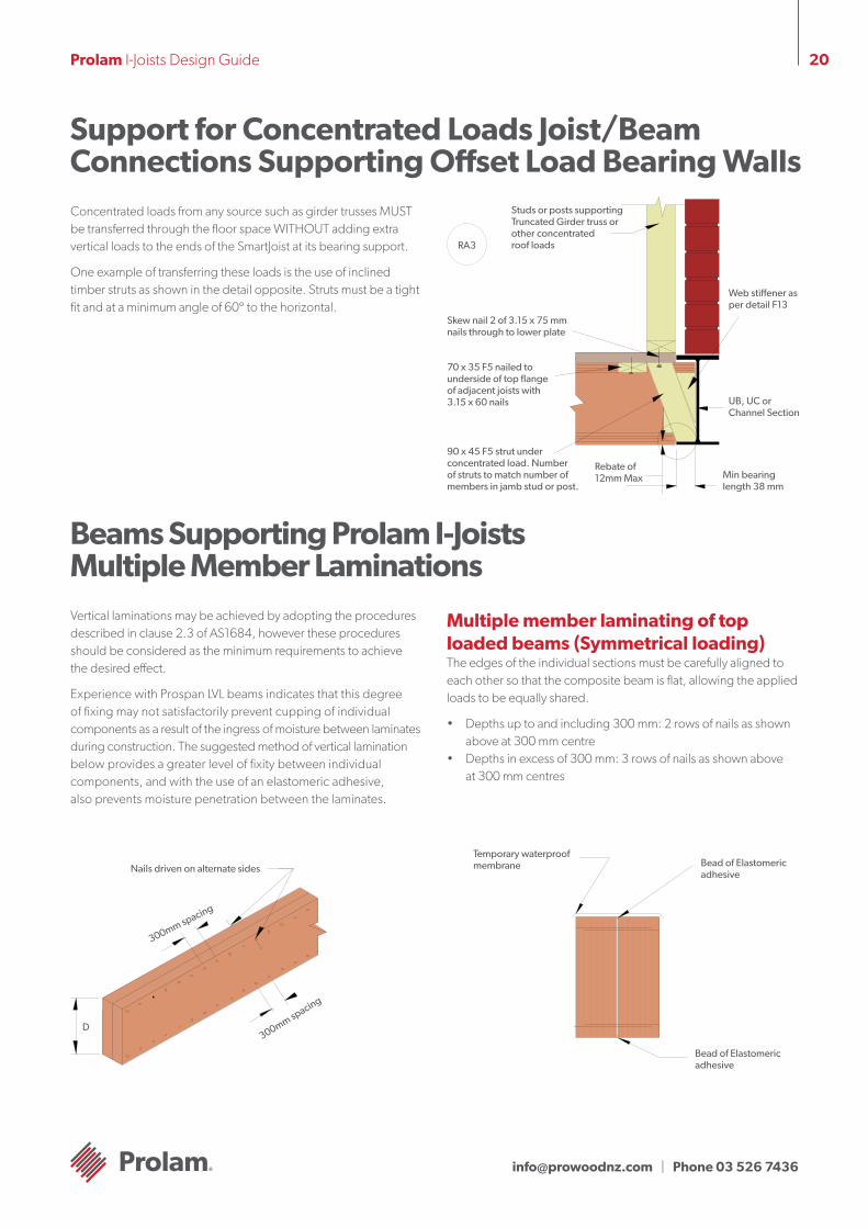
Concentrated loads from any source such as girder trusses MUST be transferred through the floor space WITHOUT adding extra vertical loads to the ends of the SmartJoist at its bearing support.
One example of transferring these loads is the use of inclined timber struts as shown in the detail opposite. Struts must be a tight fit and at a minimum angle of 60º to the horizontal.
Support for Concentrated Loads Joist/Beam Connections Supporting Offset Load Bearing Walls
90 x 45 F5 strut under concentrated load. Number of struts to match number of members in jamb stud or post.
RA3
Studs or posts supporting Truncated Girder truss or other concentrated roof loads
Skew nail 2 of 3.15 x 75 mm nails through to lower plate
70 x 35 F5 nailed to underside of top flange of adjacent joists with 3.15 x 60 nails
Web stiffener as per detail F13
UB, UC or Channel Section
Min bearing length 38 mm
Rebate of 12mm Max
Beams Supporting Prolam I-Joists Multiple Member LaminationsVertical laminations may be achieved by adopting the procedures described in clause 2.3 of AS1684, however these procedures should be considered as the minimum requirements to achieve the desired effect.
Experience with Prospan LVL beams indicates that this degree of fixing may not satisfactorily prevent cupping of individual components as a result of the ingress of moisture between laminates during construction. The suggested method of vertical lamination below provides a greater level of fixity between individual components, and with the use of an elastomeric adhesive, also prevents moisture penetration between the laminates.
Multiple member laminating of top loaded beams (Symmetrical loading)The edges of the individual sections must be carefully aligned to each other so that the composite beam is flat, allowing the applied loads to be equally shared.
• Depths up to and including 300 mm: 2 rows of nails as shown above at 300 mm centre
• Depths in excess of 300 mm: 3 rows of nails as shown above at 300 mm centres
D
Nails driven on alternate sides
300mm spacing
300mm spacing
Temporary waterproof membrane Bead of Elastomeric
adhesive
Bead of Elastomeric adhesive
[email protected] | Phone 03 526 7436
21Prolam I-Joists Design Guide
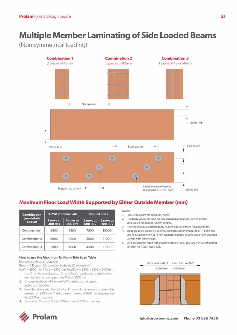
Multiple Member Laminating of Side Loaded Beams (Non-symmetrical loading)
Combination 2 3 pieces of 42mm
Combination 3 1 piece of 42 or 58mm
Nail spacing
50mm Min
50mm Min
50mm Min
50mm Min Bolt spacing
55mm diameter washer as per table 4.11-AS 1720.1Stagger row of bolts
Maximum Floor Load Width Supported by Either Outside Member (mm)
Notes: 1. Table values are for 40 kg/m2 floors.2. The table values for nails may be doubled for nails at 150 mm centres,
and tripled for nails at 100mm centres.3. The nail schedules shown apply to both sides of a three (3) piece beam.4. Bolts are to be grade 4.6 commercial bolts conforming to AS 1111. Bolt holes
are to be a maximum of 13 mm diameter and are to be located NOT less than 50 mm from either edge.
5. All bolts shall be fitted with a washer at each end, of a size NOT less than that given in AS 1720.1 table 4.11.
Combination 1 2 pieces of 42mm
How to use the Maximum Uniform Side Load TableExample: see diagram oppositeBeam of 2 Prospan LVL loaded on both side (Combination 1) FLW 1 = 2800 mm, FLW 2 = 2300 mm Total FLW = 2800 + 2300 = 5100 mm.1. Use SmartFrame software or SmartLVL safe load tables to size the two
member section to support the FLW of 5100 mm.2. Choose the larger of the side FLW’s carried by the beam,
in this case 2800mm.3. Enter the table at the “Combination 1” row and scan across to a table value
greater than 2800 mm. The first value in the row at 3600 mm is greater than the 2800 mm required.
4. Thus adopt 2 rows of 3.75ø x 90 mm nails at 300 mm centres.
Floor load width 2
=2300mm
Floor load width 1
=2800mm
Combination(see details
above)
3.75Ø x 90mm nails 12mmØ bolts
2 rows at 300 ctrs
3 rows at 300 ctrs
2 rows at 600 ctrs
2 rows at 300 ctrs
Combination 1 3400 5100 7500 15000
Combination 2 2900 4000 5600 11000
Combination 3 2900 4000 4500 11000
[email protected] | Phone 03 526 7436
22Prolam I-Joists Design Guide
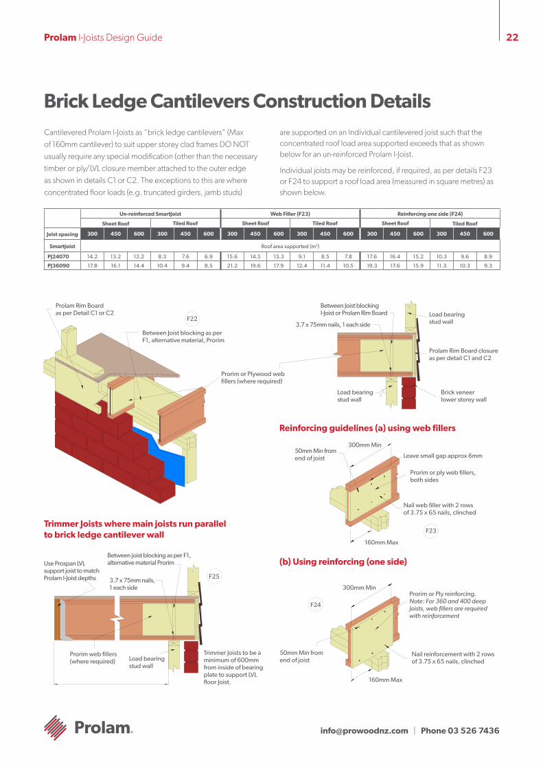
Brick Ledge Cantilevers Construction DetailsCantilevered Prolam I-Joists as “brick ledge cantilevers” (Max of 160mm cantilever) to suit upper storey clad frames DO NOT usually require any special modification (other than the necessary timber or ply/LVL closure member attached to the outer edge as shown in details C1 or C2. The exceptions to this are where concentrated floor loads (e.g. truncated girders, jamb studs)
are supported on an Individual cantilevered joist such that the concentrated roof load area supported exceeds that as shown below for an un-reinforced Prolam I-Joist.
Individual joists may be reinforced, if required, as per details F23 or F24 to support a roof load area (measured in square metres) as shown below.
Un-reinforced SmartJoist Web Filler (F23) Reinforcing one side (F24)
Sheet Roof Tiled Roof Sheet Roof Tiled Roof Sheet Roof Tiled Roof
Joist spacing 300 450 600 300 450 600 300 450 600 300 450 600 300 450 600 300 450 600
SmartJoist Roof area supported (m2)
PJ24070 14.2 13.2 12.2 8.3 7.6 6.9 15.6 14.5 13.3 9.1 8.5 7.8 17.6 16.4 15.2 10.3 9.6 8.9
PJ36090 17.8 16.1 14.4 10.4 9.4 8.5 21.2 19.6 17.9 12.4 11.4 10.5 19.3 17.6 15.9 11.3 10.3 9.3
Prolam Rim Board as per Detail C1 or C2
Prorim or Plywood web fillers (where required)
Between Joist blocking as per F1, alternative material, Prorim
F22
Trimmer Joists where main joists run parallel to brick ledge cantilever wall
Prorim web fillers (where required)
Use Prospan LVL support joist to match Prolam I-Joist depths
Load bearing stud wall
Between joist blocking as per F1, alternative material Prorim
3.7 x 75mm nails, 1 each side
F25
Trimmer Joists to be a minimum of 600mm from inside of bearing plate to support LVL floor Joist.
Load bearing stud wall
Between Joist blocking I-Joist or Prolam Rim Board
3.7 x 75mm nails, 1 each side
Load bearing stud wall
Prolam Rim Board closure as per detail C1 and C2
Brick veneer lower storey wall
Reinforcing guidelines (a) using web fillers
(b) Using reinforcing (one side)
Prorim or ply web fillers, both sides
Nail web filler with 2 rows of 3.75 x 65 nails, clinched
Leave small gap approx 6mm
F23
160mm Max
300mm Min50mm Min from end of joist
300mm Min
F24
Prorim or Ply reinforcing.Note: For 360 and 400 deep Joists, web fillers are required with reinforcement
Nail reinforcement with 2 rows of 3.75 x 65 nails, clinched
160mm Max
50mm Min from end of joist
[email protected] | Phone 03 526 7436
23Prolam I-Joists Design Guide
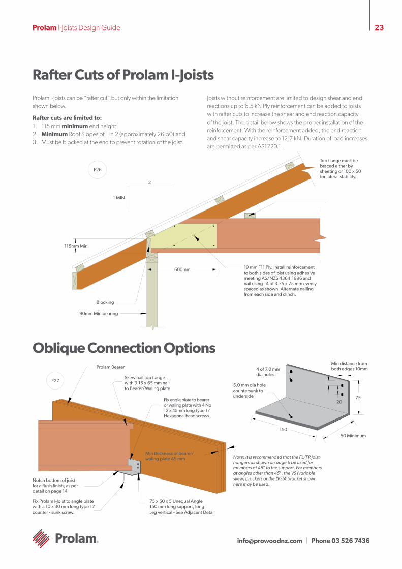
Rafter Cuts of Prolam I-JoistsProlam I-Joists can be “rafter cut” but only within the limitation shown below.
Rafter cuts are limited to:1. 115 mm minimum end height2. Minimum Roof Slopes of 1 in 2 (approximately 26.50),and3. Must be blocked at the end to prevent rotation of the joist.
Joists without reinforcement are limited to design shear and end reactions up to 6.5 kN Ply reinforcement can be added to joists with rafter cuts to increase the shear and end reaction capacity of the joist. The detail below shows the proper installation of the reinforcement. With the reinforcement added, the end reaction and shear capacity increase to 12.7 kN. Duration of load increases are permitted as per AS1720.1.
Oblique Connection Options
115mm Min
2
F26
1 MIN
Blocking
90mm Min bearing
600mm 19 mm F11 Ply. Install reinforcement to both sides of joist using adhesive meeting AS/NZS 4364:1996 and nail using 14 of 3.75 x 75 mm evenly spaced as shown. Alternate nailing from each side and clinch.
Top flange must be braced either by sheeting or 100 x 50 for lateral stability.
Prolam Bearer
F27
Note: It is recommended that the FL/FR joist hangers as shown on page 6 be used for members at 45° to the support. For members at angles other than 45°, the VS (variable skew) brackets or the LVSIA bracket shown here may be used.
Skew nail top flange with 3.15 x 65 mm nail to Bearer/Waling plate
Fix angle plate to bearer or waling plate with 4 No 12 x 45mm long Type 17 Hexagonal head screws.
Min thickness of bearer/ waling plate 45 mm
75 x 50 x 5 Unequal Angle 150 mm long support, long Leg vertical - See Adjacent Detail
Fix Prolam I-Joist to angle plate with a 10 x 30 mm long type 17 counter - sunk screw.
Notch bottom of joist for a flush finish, as per detail on page 14
150
75
50 Minimum
20
Min distance from both edges 10mm4 of 7.0 mm
dia holes
5.0 mm dia hole countersunk to underside
[email protected] | Phone 03 526 7436
24Prolam I-Joists Design Guide
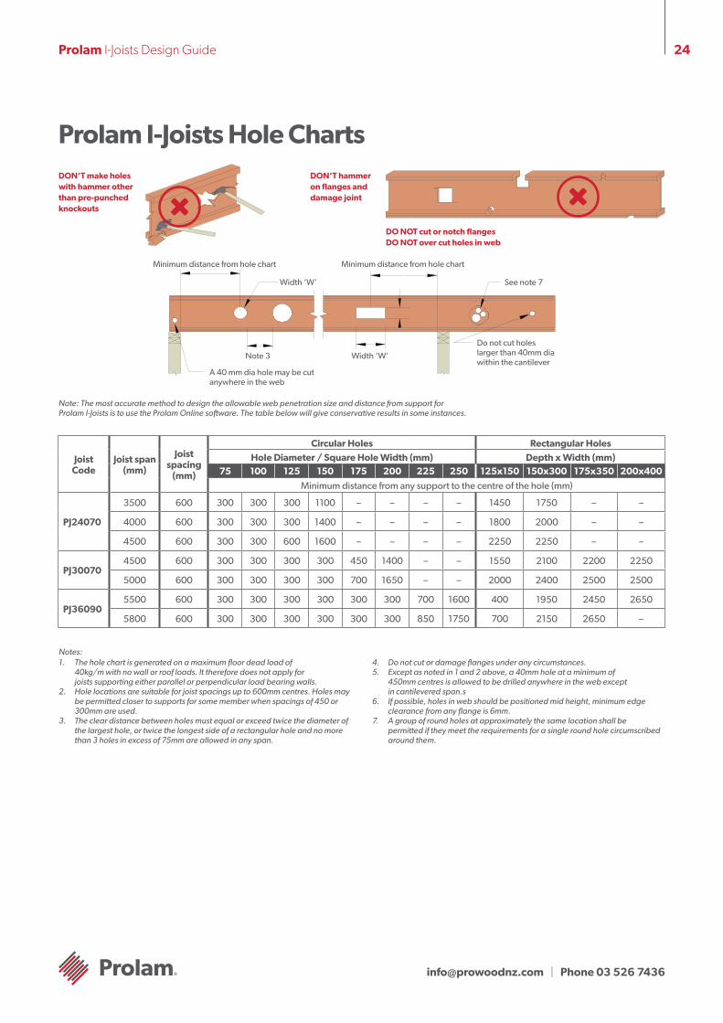
Prolam I-Joists Hole ChartsDON’T make holes with hammer other than pre-punched knockouts
DON’T hammer on flanges and damage joint
DO NOT cut or notch flanges DO NOT over cut holes in web
Minimum distance from hole chart
See note 7
Do not cut holes larger than 40mm dia within the cantilever
Width ‘W’Note 3
Minimum distance from hole chart
Width ‘W’
A 40 mm dia hole may be cut anywhere in the web
Note: The most accurate method to design the allowable web penetration size and distance from support for Prolam I-Joists is to use the Prolam Online software. The table below will give conservative results in some instances.
Joist Code
Joist span (mm)
Joist spacing
(mm)
Circular Holes Rectangular Holes
Hole Diameter / Square Hole Width (mm) Depth x Width (mm)75 100 125 150 175 200 225 250 125x150 150x300 175x350 200x400
Minimum distance from any support to the centre of the hole (mm)
PJ24070
3500 600 300 300 300 1100 – – – – 1450 1750 – –
4000 600 300 300 300 1400 – – – – 1800 2000 – –
4500 600 300 300 600 1600 – – – – 2250 2250 – –
PJ300704500 600 300 300 300 300 450 1400 – – 1550 2100 2200 2250
5000 600 300 300 300 300 700 1650 – – 2000 2400 2500 2500
PJ360905500 600 300 300 300 300 300 300 700 1600 400 1950 2450 2650
5800 600 300 300 300 300 300 300 850 1750 700 2150 2650 –
1. The hole chart is generated on a maximum floor dead load of 40kg/m with no wall or roof loads. It therefore does not apply for joists supporting either parallel or perpendicular load bearing walls.
2. Hole locations are suitable for joist spacings up to 600mm centres. Holes may be permitted closer to supports for some member when spacings of 450 or 300mm are used.
3. The clear distance between holes must equal or exceed twice the diameter of the largest hole, or twice the longest side of a rectangular hole and no more than 3 holes in excess of 75mm are allowed in any span.
4. Do not cut or damage flanges under any circumstances.5. Except as noted in 1 and 2 above, a 40mm hole at a minimum of
450mm centres is allowed to be drilled anywhere in the web except in cantilevered span.s
6. If possible, holes in web should be positioned mid height, minimum edge clearance from any flange is 6mm.
7. A group of round holes at approximately the same location shall be permitted if they meet the requirements for a single round hole circumscribed around them.
Notes:
[email protected] | Phone 03 526 7436
25Prolam I-Joists Design Guide
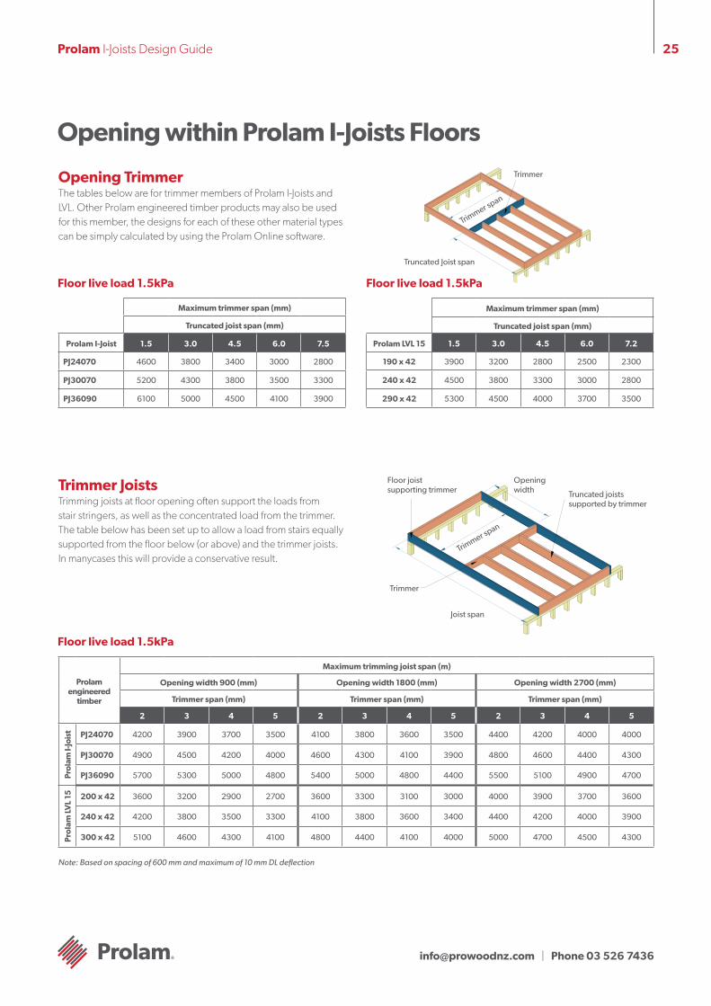
Opening within Prolam I-Joists Floors
Opening Trimmer The tables below are for trimmer members of Prolam I-Joists and LVL. Other Prolam engineered timber products may also be used for this member, the designs for each of these other material types can be simply calculated by using the Prolam Online software.
Trimmer
Truncated Joist span
Trimmer span
Maximum trimmer span (mm)
Truncated joist span (mm)
Prolam I-Joist 1.5 3.0 4.5 6.0 7.5
PJ24070 4600 3800 3400 3000 2800
PJ30070 5200 4300 3800 3500 3300
PJ36090 6100 5000 4500 4100 3900
Floor live load 1.5kPa Floor live load 1.5kPa
Maximum trimmer span (mm)
Truncated joist span (mm)
Prolam LVL 15 1.5 3.0 4.5 6.0 7.2
190 x 42 3900 3200 2800 2500 2300
240 x 42 4500 3800 3300 3000 2800
290 x 42 5300 4500 4000 3700 3500
Trimmer Joists Trimming joists at floor opening often support the loads from stair stringers, as well as the concentrated load from the trimmer. The table below has been set up to allow a load from stairs equally supported from the floor below (or above) and the trimmer joists. In manycases this will provide a conservative result.
Floor joist supporting trimmer
Opening width
Trimmer span
Truncated joists supported by trimmer
Trimmer
Joist span
Prolam engineered
timber
Maximum trimming joist span (m)
Opening width 900 (mm) Opening width 1800 (mm) Opening width 2700 (mm)
Trimmer span (mm) Trimmer span (mm) Trimmer span (mm)
2 3 4 5 2 3 4 5 2 3 4 5
Pro
lam
I-Jo
ist PJ24070 4200 3900 3700 3500 4100 3800 3600 3500 4400 4200 4000 4000
PJ30070 4900 4500 4200 4000 4600 4300 4100 3900 4800 4600 4400 4300
PJ36090 5700 5300 5000 4800 5400 5000 4800 4400 5500 5100 4900 4700
Pro
lam
LVL
15 200 x 42 3600 3200 2900 2700 3600 3300 3100 3000 4000 3900 3700 3600
240 x 42 4200 3800 3500 3300 4100 3800 3600 3400 4400 4200 4000 3900
300 x 42 5100 4600 4300 4100 4800 4400 4100 4000 5000 4700 4500 4300
Floor live load 1.5kPa
Note: Based on spacing of 600 mm and maximum of 10 mm DL deflection
[email protected] | Phone 03 526 7436
26Prolam I-Joists Design Guide
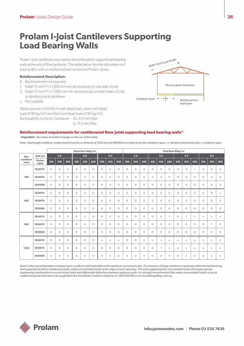
Prolam I-Joist Cantilevers Supporting Load Bearing WallsProlam I-Joist cantilevers may need to be reinforced to support load bearing walls at the end of the cantilever. The table below lists the allowable roof load widths with un-reinforced and reinforced Prolam I-Joists.
Reinforcement Description: 0. Reinforcement not required1. Install 15 mm F11 x 1200 mm min structural ply on one side of joist2. Install 15 mm F11 x 1200 mm min structural ply on both sides of joist
or double joist at cantileverx. Not suitable
Tables assume a 0.8 kN/m wall dead load, sheet roof dead load of 40 kg/m2 and tiled roof dead load of 90 kg/m2. Serviceability Limits on Cantilever - DL: 6.0 mm Max LL: 4.5 mm Max
Cantilever span Reinforcement back span
Ply face grain horizontal
RLW= Roof Load Width
Reinforcement requirements for cantilevered floor joists supporting load bearing walls**Important : See notes at bottom of page on the use of this table
Note: Total length cantilever reinforcement must be a minimum of 1200 mm but NEVER be less than twice the cantilever span. i.e. Reinforcement back span ≥ cantilever span.
Sheet Roof 40kg/m2 Tiled Roof 90kg/m2
Max cantilever
(mm)
RLW (m) 4.0 6.0 8.0 2.0 4.0 6.0 8.0
Prolam I-Joist
300 450 600 300 450 600 300 450 600 300 450 600 300 450 600 300 450 600 300 450 600
300
PJ24070 0 0 0 0 0 0 0 0 0 0 0 0 0 0 0 0 0 1 0 0 2
PJ30070 0 0 0 0 0 0 0 0 0 0 0 0 0 0 0 0 0 0 0 0 0
PJ36090 0 0 0 0 0 0 0 0 0 0 0 0 0 0 0 0 0 0 0 0 0
600
PJ24070 0 0 0 0 0 0 0 0 0 0 0 0 0 0 0 0 0 0 0 0 x
PJ30070 0 0 0 0 0 0 0 0 0 0 0 0 0 0 0 0 0 0 0 0 0
PJ36090 0 0 0 0 0 0 0 0 0 0 0 0 0 0 0 0 0 0 0 0 0
900
PJ24070 0 0 0 0 0 0 0 0 0 0 0 0 0 0 1 0 1 x x x x
PJ30070 0 0 0 0 0 0 0 0 0 0 0 0 0 0 0 0 0 0 0 1 2
PJ36090 0 0 0 0 0 0 0 0 0 0 0 0 0 0 0 0 0 0 0 0 0
1200
PJ24070 0 0 0 0 0 0 x x x 0 0 x x x x x x x x x x
PJ30070 0 0 0 0 0 0 0 0 0 0 0 0 0 1 x x x x x x x
PJ36090 0 0 0 0 0 0 0 0 0 0 0 0 0 0 0 0 2 0 0 2 x
Spans in the preceding table are based upon a uniform roof load width at the cantilever end of each joist. The presence of large windows or openings within the load bearing wall supported by these cantilevered joists create concentrated loads at the edges of such openings. The joists supporting the concentrated loads will require special engineering consideration to avoid excess loads and differential deflections between adjacent joists. It is strongly recommended that where concentrated loads occur on cantilevered joists that advice be sought from the SmartData Customer HelpLine on 1300 668 690 or at [email protected].
[email protected] | Phone 03 526 7436
27Prolam I-Joists Design Guide
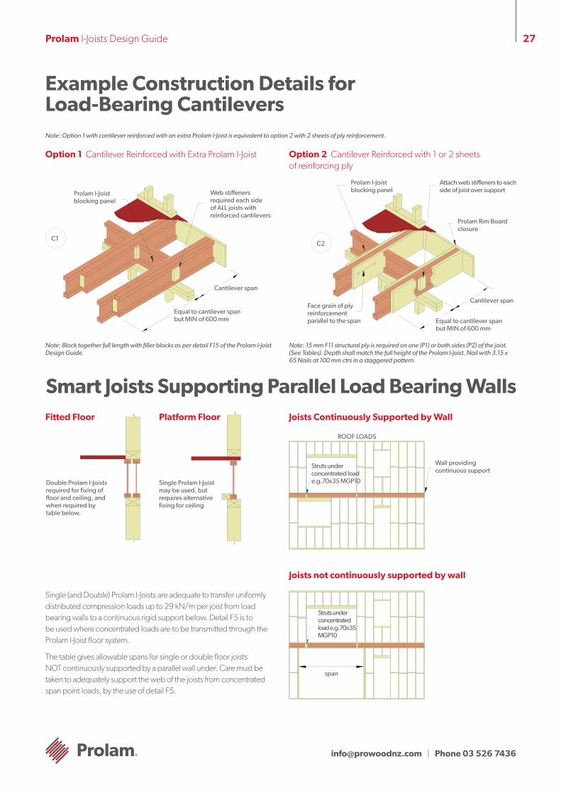
Example Construction Details for Load-Bearing CantileversNote: Option 1 with cantilever reinforced with an extra Prolam I-Joist is equivalent to option 2 with 2 sheets of ply reinforcement.
Option 1 Cantilever Reinforced with Extra Prolam I-Joist Option 2 Cantilever Reinforced with 1 or 2 sheets of reinforcing ply
Cantilever span
C1
Equal to cantilever span but MIN of 600 mm
Web stiffeners required each side of ALL joists with reinforced cantilevers
Prolam I-Joist blocking panel
Note: Block together full length with filler blocks as per detail F15 of the Prolam I-Joist Design Guide.
Note: 15 mm F11 structural ply is required on one (P1) or both sides (P2) of the joist. (See Tables). Depth shall match the full height of the Prolam I-Joist. Nail with 3.15 x 65 Nails at 100 mm ctrs in a staggered pattern.
Equal to cantilever span but MIN of 600 mm
Cantilever span
C2
Prolam I-Joist blocking panel
Prolam Rim Board closure
Attach web stiffeners to each side of joist over support
Face grain of ply reinforcement parallel to the span
Smart Joists Supporting Parallel Load Bearing WallsFitted Floor Platform Floor
Double Prolam I-Joists required for fixing of floor and ceiling, and when required by table below.
Single Prolam I-Joist may be used, but requires alternative fixing for ceiling
Joists Continuously Supported by Wall
Wall providing continuous support
Struts under concentrated load e.g.70x35 MGP10
ROOF LOADS
Joists not continuously supported by wall
span
Struts under concentrated load e.g.70x35 MGP10
Single (and Double) Prolam I-Joists are adequate to transfer uniformlydistributed compression loads up to 29 kN/m per joist from loadbearing walls to a continuous rigid support below. Detail F5 is tobe used where concentrated loads are to be transmitted through theProlam I-Joist floor system.
The table gives allowable spans for single or double floor joistsNOT continuously supported by a parallel wall under. Care must betaken to adequately support the web of the joists from concentratedspan point loads, by the use of detail F5.
[email protected] | Phone 03 526 7436
28Prolam I-Joists Design Guide
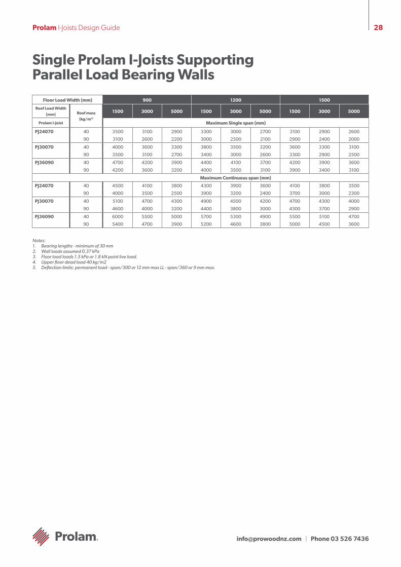
Single Prolam I-Joists Supporting Parallel Load Bearing Walls
Floor Load Width (mm) 900 1200 1500
Roof Load Width
(mm) Roof mass
(kg/m2)
1500 3000 5000 1500 3000 5000 1500 3000 5000
Prolam I-Joist Maximum Single span (mm)
PJ24070 40 3500 3100 2900 3300 3000 2700 3100 2900 2600
90 3100 2600 2200 3000 2500 2100 2900 2400 2000
PJ30070 40 4000 3600 3300 3800 3500 3200 3600 3300 3100
90 3500 3100 2700 3400 3000 2600 3300 2900 2500
PJ36090 40 4700 4200 3900 4400 4100 3700 4200 3900 3600
90 4200 3600 3200 4000 3500 3100 3900 3400 3100
Maximum Continuous span (mm)
PJ24070 40 4500 4100 3800 4300 3900 3600 4100 3800 3500
90 4000 3500 2500 3900 3200 2400 3700 3000 2300
PJ30070 40 5100 4700 4300 4900 4500 4200 4700 4300 4000
90 4600 4000 3200 4400 3800 3000 4300 3700 2900
PJ36090 40 6000 5500 5000 5700 5300 4900 5500 5100 4700
90 5400 4700 3900 5200 4600 3800 5000 4500 3600
Notes:1. Bearing lengths - minimum of 30 mm2. Wall loads assumed 0.37 kPa3. Floor load loads 1.5 kPa or 1.8 kN point live load.4. Upper floor dead load 40 kg/m25. Deflection limits: permanent load - span/300 or 12 mm max LL - span/360 or 9 mm max.
[email protected] | Phone 03 526 7436
29Prolam I-Joists Design Guide
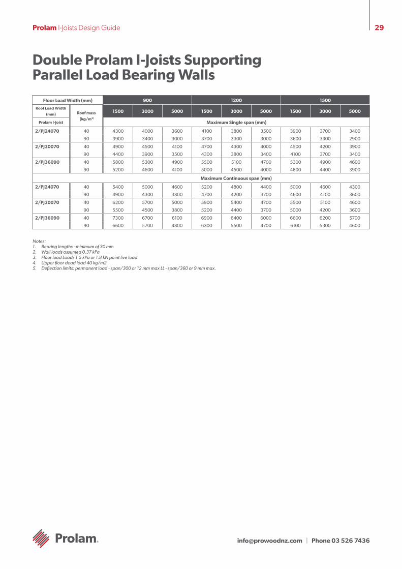
Double Prolam I-Joists Supporting Parallel Load Bearing Walls
Floor Load Width (mm) 900 1200 1500
Roof Load Width
(mm) Roof mass
(kg/m2)
1500 3000 5000 1500 3000 5000 1500 3000 5000
Prolam I-Joist Maximum Single span (mm)
2/PJ24070 40 4300 4000 3600 4100 3800 3500 3900 3700 3400
90 3900 3400 3000 3700 3300 3000 3600 3300 2900
2/PJ30070 40 4900 4500 4100 4700 4300 4000 4500 4200 3900
90 4400 3900 3500 4300 3800 3400 4100 3700 3400
2/PJ36090 40 5800 5300 4900 5500 5100 4700 5300 4900 4600
90 5200 4600 4100 5000 4500 4000 4800 4400 3900
Maximum Continuous span (mm)
2/PJ24070 40 5400 5000 4600 5200 4800 4400 5000 4600 4300
90 4900 4300 3800 4700 4200 3700 4600 4100 3600
2/PJ30070 40 6200 5700 5000 5900 5400 4700 5500 5100 4600
90 5500 4500 3800 5200 4400 3700 5000 4200 3600
2/PJ36090 40 7300 6700 6100 6900 6400 6000 6600 6200 5700
90 6600 5700 4800 6300 5500 4700 6100 5300 4600
Notes:1. Bearing lengths - minimum of 30 mm2. Wall loads assumed 0.37 kPa3. Floor load Loads 1.5 kPa or 1.8 kN point live load.4. Upper floor dead load 40 kg/m25. Deflection limits: permanent load - span/300 or 12 mm max LL - span/360 or 9 mm max.
[email protected] | Phone 03 526 7436
30Prolam I-Joists Design Guide
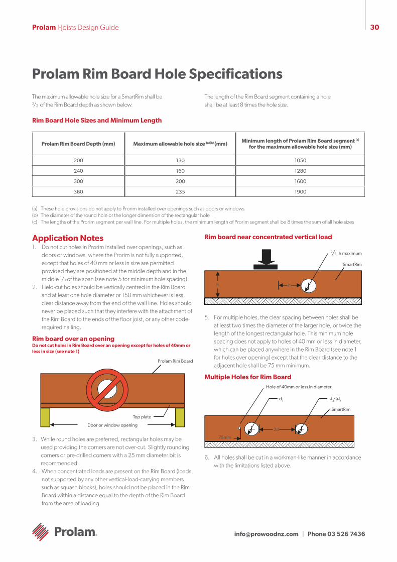
Application Notes 1. Do not cut holes in Prorim installed over openings, such as
doors or windows, where the Prorim is not fully supported, except that holes of 40 mm or less in size are permitted provided they are positioned at the middle depth and in the middle 1/3 of the span (see note 5 for minimum hole spacing).
2. Field-cut holes should be vertically centred in the Rim Board and at least one hole diameter or 150 mm whichever is less, clear distance away from the end of the wall line. Holes should never be placed such that they interfere with the attachment of the Rim Board to the ends of the floor joist, or any other code-required nailing.
Rim board over an opening Do not cut holes in Rim Board over an opening except for holes of 40mm or less in size (see note 1)
3. While round holes are preferred, rectangular holes may be used providing the corners are not over-cut. Slightly rounding corners or pre-drilled corners with a 25 mm diameter bit is recommended.
4. When concentrated loads are present on the Rim Board (loads not supported by any other vertical-load-carrying members such as squash blocks), holes should not be placed in the Rim Board within a distance equal to the depth of the Rim Board from the area of loading.
Rim board near concentrated vertical load
5. For multiple holes, the clear spacing between holes shall be at least two times the diameter of the larger hole, or twice the length of the longest rectangular hole. This minimum hole spacing does not apply to holes of 40 mm or less in diameter, which can be placed anywhere in the Rim Board (see note 1 for holes over opening) except that the clear distance to the adjacent hole shall be 75 mm minimum.
Multiple Holes for Rim Board
6. All holes shall be cut in a workman-like manner in accordance with the limitations listed above.
Prolam Rim Board Hole SpecificationsThe maximum allowable hole size for a SmartRim shall be 2/3 of the Rim Board depth as shown below.
The length of the Rim Board segment containing a holeshall be at least 8 times the hole size.
Prolam Rim Board
Door or window opening
Top plate
2/3 h maximum
SmartRim
h h
Hole of 40mm or less in diameter
SmartRim
75mm
2d
d1d2<d1
Prolam Rim Board Depth (mm) Maximum allowable hole size (a)(b) (mm) Minimum length of Prolam Rim Board segment (c) for the maximum allowable hole size (mm)
200 130 1050
240 160 1280
300 200 1600
360 235 1900
Rim Board Hole Sizes and Minimum Length
(a) These hole provisions do not apply to Prorim installed over openings such as doors or windows(b) The diameter of the round hole or the longer dimension of the rectangular hole(c) The lengths of the Prorim segment per wall line. For multiple holes, the minimum length of Prorim segment shall be 8 times the sum of all hole sizes
[email protected] | Phone 03 526 7436
31Prolam I-Joists Design Guide
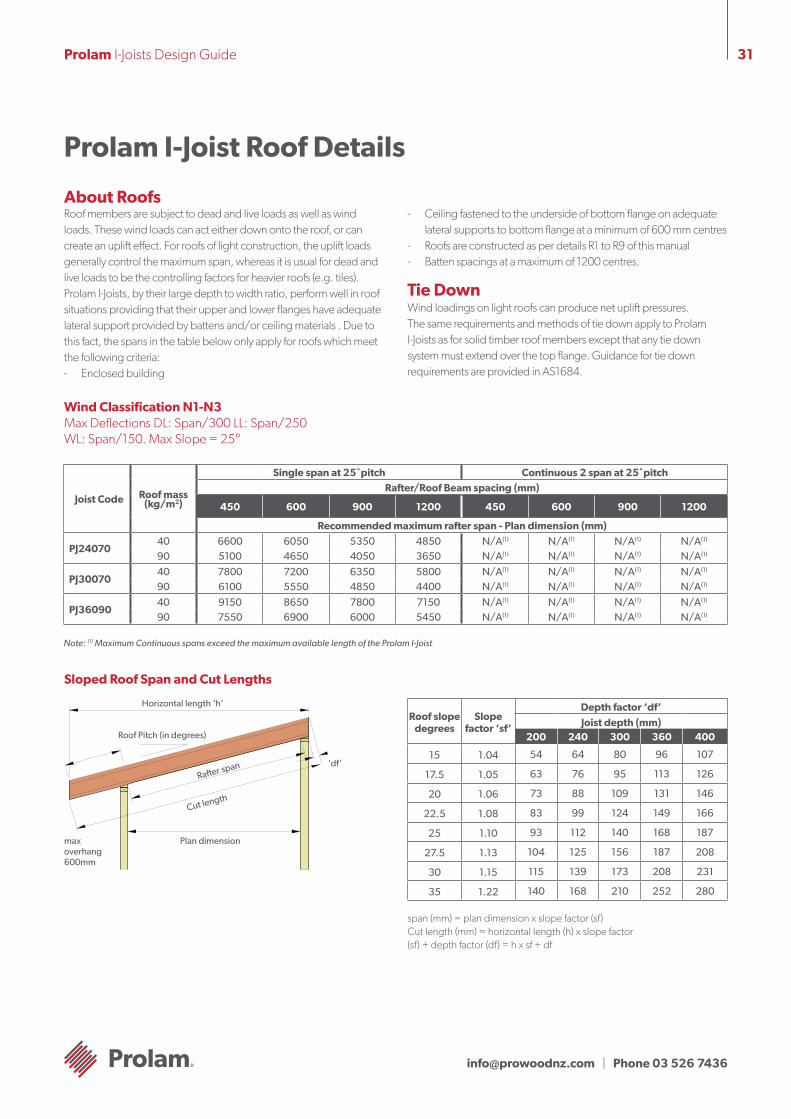
Prolam I-Joist Roof Details
Roof members are subject to dead and live loads as well as wind loads. These wind loads can act either down onto the roof, or can create an uplift effect. For roofs of light construction, the uplift loads generally control the maximum span, whereas it is usual for dead and live loads to be the controlling factors for heavier roofs (e.g. tiles).Prolam I-Joists, by their large depth to width ratio, perform well in roof situations providing that their upper and lower flanges have adequate lateral support provided by battens and/or ceiling materials . Due to this fact, the spans in the table below only apply for roofs which meet the following criteria:- Enclosed building
- Ceiling fastened to the underside of bottom flange on adequate lateral supports to bottom flange at a minimum of 600 mm centres
- Roofs are constructed as per details R1 to R9 of this manual- Batten spacings at a maximum of 1200 centres.
Tie DownWind loadings on light roofs can produce net uplift pressures. The same requirements and methods of tie down apply to Prolam I-Joists as for solid timber roof members except that any tie down system must extend over the top flange. Guidance for tie down requirements are provided in AS1684.
About Roofs
Joist Code Roof mass (kg/m2)
Single span at 25˚pitch Continuous 2 span at 25˚pitchRafter/Roof Beam spacing (mm)
450 600 900 1200 450 600 900 1200
Recommended maximum rafter span - Plan dimension (mm)
PJ2407040 6600 6050 5350 4850 N/A(1) N/A(1) N/A(1) N/A(1)
90 5100 4650 4050 3650 N/A(1) N/A(1) N/A(1) N/A(1)
PJ3007040 7800 7200 6350 5800 N/A(1) N/A(1) N/A(1) N/A(1)
90 6100 5550 4850 4400 N/A(1) N/A(1) N/A(1) N/A(1)
PJ3609040 9150 8650 7800 7150 N/A(1) N/A(1) N/A(1) N/A(1)
90 7550 6900 6000 5450 N/A(1) N/A(1) N/A(1) N/A(1)
Wind Classification N1-N3 Max Deflections DL: Span/300 LL: Span/250 WL: Span/150. Max Slope = 25°
Note: (1) Maximum Continuous spans exceed the maximum available length of the Prolam I-Joist
Sloped Roof Span and Cut Lengths
Horizontal length ‘h’
Roof Pitch (in degrees)
Plan dimensionmax overhang 600mm
‘df’
Cut length
Rafter span
Roof slope degrees
Slope factor ‘sf’
Depth factor ‘df’
Joist depth (mm)200 240 300 360 400
15 1.04 54 64 80 96 107
17.5 1.05 63 76 95 113 126
20 1.06 73 88 109 131 146
22.5 1.08 83 99 124 149 166
25 1.10 93 112 140 168 187
27.5 1.13 104 125 156 187 208
30 1.15 115 139 173 208 231
35 1.22 140 168 210 252 280
span (mm) = plan dimension x slope factor (sf)Cut length (mm) = horizontal length (h) x slope factor(sf) + depth factor (df) = h x sf + df
[email protected] | Phone 03 526 7436
32Prolam I-Joists Design Guide
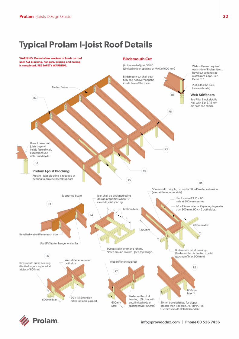
Typical Prolam I-Joist Roof DetailsWARNING: Do not allow workers or loads on roof until ALL blocking, hangers, bracing and nailing is completed. SEE SAFETY WARNING.
Birdsmouth Cut
R1
Birdsmouth cut shall bear fully and not overhang the inside face of the plate.
Web stiffeners required each side of Prolam I-Joist. Bevel cut stiffeners to match roof slope. See Detail F13.
2 of 3.15 x 65 nails (one each side)
(At low end of joist ONLY) (Limited to Joist spacing of MAX of 600 mm)
Web StiffenersSee Filler Block details Nail with 5 of 3.15 mm dia nails and clinch.
R8
R7
R6
R5
R2
R3
Prolam Beam
Do not bevel cut joists beyond inside face of wall.Exception: See rafter cut details.
Prolam I-Joist BlockingProlam I-Joist blocking is required at bearing to provide lateral support
R3
R4
R5
R6
R7R8
Supported beam
Bevelled web stiffener each side
Use LFVS rafter hanger or similar
Joist shall be designed using design properties when “L” exceeds joist spacing.
L
L
600mm Max
50mm width overhang rafters. Notch around Prolam I-Joist top flange.
1200mm
50mm width cripple, cut under 90 x 45 rafter extension (Web stiffener other side)
Use 2 rows of 3.15 x 65 nails at 200 mm centres
90 x 45 one side, or if spacing is greater than 900 mm, 90 x 45 both sides.
600mm Max
Birdsmouth cut at bearing.(Birdsmouth cuts limited to joist spacing of Max 600 mm)
600mm Max
50mm beveled plate for slopes greater than 1 degree. ALTERNATIVE: Use birdsmouth details R1and R7.
600mm Max
Web stiffener required
Birdsmouth cut at bearing. (Birdsmouth cuts limited to joist spacing of Max 600mm)
Web stiffener required both sideBirdsmouth cut at bearing.
(Limited to joists spaced at a Max of 600mm)
600mm Max90 x 45 Extension rafter for facia support
[email protected] | Phone 03 526 7436
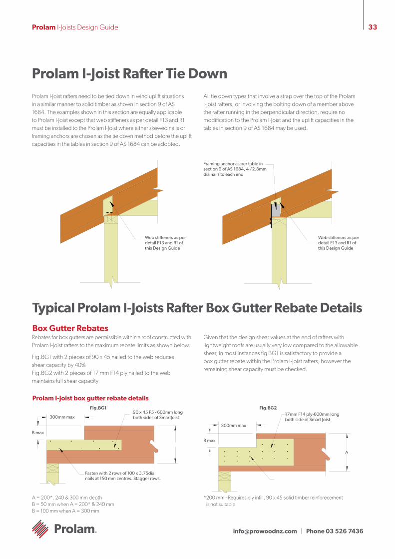
33Prolam I-Joists Design Guide
Prolam I-Joist Rafter Tie DownProlam I-Joist rafters need to be tied down in wind uplift situations in a similar manner to solid timber as shown in section 9 of AS 1684. The examples shown in this section are equally applicable to Prolam I-Joist except that web stiffeners as per detail F13 and R1 must be installed to the Prolam I-Joist where either skewed nails or framing anchors are chosen as the tie down method before the uplift capacities in the tables in section 9 of AS 1684 can be adopted.
All tie down types that involve a strap over the top of the Prolam I-Joist rafters, or involving the bolting down of a member above the rafter running in the perpendicular direction, require no modification to the Prolam I-Joist and the uplift capacities in the tables in section 9 of AS 1684 may be used.
Framing anchor as per table in section 9 of AS 1684, 4 /2.8mm dia nails to each end
Web stiffeners as per detail F13 and R1 of this Design Guide
Web stiffeners as per detail F13 and R1 of this Design Guide
Typical Prolam I-Joists Rafter Box Gutter Rebate Details
Rebates for box gutters are permissible within a roof constructed with Prolam I-Joist rafters to the maximum rebate limits as shown below.
Fig.BG1 with 2 pieces of 90 x 45 nailed to the web reduces shear capacity by 40% Fig.BG2 with 2 pieces of 17 mm F14 ply nailed to the web maintains full shear capacity
Given that the design shear values at the end of rafters with lightweight roofs are usually very low compared to the allowable shear, in most instances fig BG1 is satisfactory to provide a box gutter rebate within the Prolam I-Joist rafters, however the remaining shear capacity must be checked.
Box Gutter Rebates
Prolam I-Joist box gutter rebate details
B max
300mm max
17mm F14 ply-600mm long both side of Smart Joist
Fasten with 2 rows of 100 x 3.75dia nails at 150 mm centres. Stagger rows.
A
B max
300mm max90 x 45 F5 - 600mm long both sides of SmartJoist
A = 200*, 240 & 300 mm depthB = 50 mm when A = 200* & 240 mmB = 100 mm when A = 300 mm
* 200 mm - Requires ply infill, 90 x 45 solid timber reinforecement is not suitable
Fig.BG1 Fig.BG2
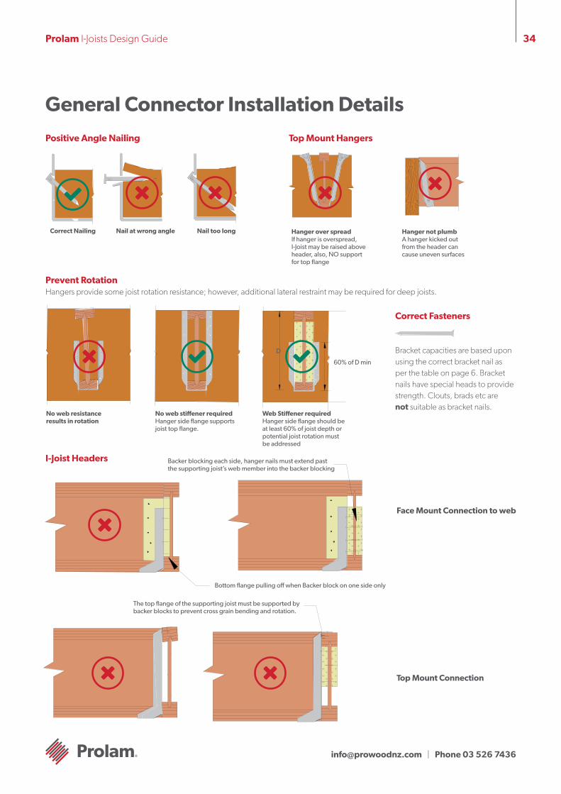
[email protected] | Phone 03 526 7436
34Prolam I-Joists Design Guide
General Connector Installation Details
Positive Angle Nailing Top Mount Hangers
Correct Nailing Nail at wrong angle Nail too long Hanger over spread If hanger is overspread, I-Joist may be raised above header, also, NO support for top flange
Hanger not plumb A hanger kicked out from the header can cause uneven surfaces
Prevent Rotation Hangers provide some joist rotation resistance; however, additional lateral restraint may be required for deep joists.
D
60% of D min
No web resistance results in rotation
No web stiffener required Hanger side flange supports joist top flange.
Web Stiffener requiredHanger side flange should be at least 60% of joist depth or potential joist rotation must be addressed
Correct Fasteners
Bracket capacities are based upon using the correct bracket nail as per the table on page 6. Bracket nails have special heads to provide strength. Clouts, brads etc are not suitable as bracket nails.
I-Joist Headers
Top Mount Connection
Face Mount Connection to web
Backer blocking each side, hanger nails must extend past the supporting joist’s web member into the backer blocking
Bottom flange pulling off when Backer block on one side only
The top flange of the supporting joist must be supported by backer blocks to prevent cross grain bending and rotation.

[email protected] | Phone 03 526 7436
35Prolam I-Joists Design Guide
Fire Safety The Building code of Australia became a performance based code in 1996 (BCA96). The introduction of the BCA along with the changes to AS1530.4 has seen Australia brought into line with international standards for fire resistance testing. The principle modification has been to express the test result in terms of the performance of the specimen Fire Resistance Level (FRL) rather than to assign a single rating as had been the established practice. The outcome of the test is expressed as the number of minutes for which the specimen fulfils the requirements of each of the three criteria, being: a) Structural adequacy b) Integrity; and c) Insulation, and expressed in that order
The performance of a specimen is then given as the actual time for which the specimen satisfied these criteria, but rounded down to the nearest regulatory requirements. e.g. 60/60/60.
Ceiling systems may also be required to provide “Resistance to the Incipient Spread of fire” for a given period of time. This requires the ceiling system to prevent the spread of fire within a roof/ceiling or floor/ceiling cavity by providing adequate thermal insulation to combustibles in this area, avoiding the danger of them igniting. To coincide with the changes, the timber industry produced a set of manuals Multi Residential Timber Framed Construction (MRTFC) 1, 2 & 3, which outlined the BCA requirements for multi residential buildings, design criteria and
construction details which were designed to satisfy the BCA requirements.
Fire Rated Floors/CeilingsThe best information available at this time concludes that the fire resistance for ceiling and floor/ceilings is achieved by the lining material and that alternative joist sizes and material can be substituted in the various certified systems, providing they are designed to support the full loads. The thickness of the fire grade ceiling lining for the relevant FRL is the same as required in the tested systems using solid timber joists.
Additional testing have concluded that the following layers of fire rated plasterboard can achieve the FRL and incipient spread of fire as listed in the following table:
The above ratings can be achieved using standard fire grade plasterboard from some sheet manufacturers. Other manufacturers may however require the use of special fire rated board or may still require the number of layers outlined in MRTFC 2.
For further details on the various certified systems, see the MRTFC manuals available through all State Timber Development Associations or contact the
engineers on the SmartData Customer HelpLine on 1300 668 690.
Sound TranmissionThe ability of walls and floors to reduce noise is measured over the most important part of the hearing range (from 125 to 4000 cycles per second), and the results reduced to a “weighted sound reduction index” or Rw value. In 2004, the BCA introduced the addition of a Spectrum Adaption factor. This Ctr factor takes into account lower frequency level sounds, and has been chosen in large part, in recognition of the problem of the high bass frequency outputs of modern home theatre systems and amplified music systems. Therefore, both the Ctr and the Rw of the building element will now need to be considered.
In addition to being rated for airborne sound transmission, floors are also rated by “Impact sound pressure level” or L’n,w plus the spectrum adaption factor Cl values that rate the capacity of floor assemblies to control impact noise such as footfalls. The lower the L’n,w +Cl of the floor, the better the performance of the floor in terms of impact sound insulation.
The BCA now requires a Rw+Ctr of 50 in floors between sole occupancy units and between dwellings and a plant room, lift shaft, stairway, public corridor, public lobby or similar.
In 2004, the BCA introduced Deemed-to-satisfy provisions which require the L’n,w +Cl of a floor to be determined by testing in the laboratory. The impact sound insulation requirements for floors in the BCA is L’n,w +Cl not more than 62 for floor separating dwellings and floor separating dwellings from a plant room, lift shaft, stairway, public corridor, public lobby or similar.
The use of light-frame construction systems challenges designers to insulate against noise rather than simply relying on the massiveness of heavy walls and floors. Excellent levels of noise control can be achieved with good acoustics in wood framed structures surfaced with wood structural panels. Sound control can be achieved by applying floor and wall materials over isolated air spaces that absorb sound. The addition of resilient channels to support the ceiling system independently increases the Rw+Ctr and L’n,w +Cl ratings.
The best current understanding indicates that the “Certified Systems – Walls, Floors and Ceiling” as detailed in the MRTFC 2 can be used to closely approximate the Rw+Ctr and L’n,w +Cl rating of floor/ceiling systems with SmartJoist floor joists. Work is under way to further investigate the link between joist types and impact sound insulation.
For further details on the various certified systems, see the MRTFC manuals available through all State Timber Development Associations or contact the engineers on the SmartData Customer HelpLine on 1300 668 690 or at [email protected]
The treatment of timber to extend its service life is covered by AS/NZS 1604. This code identifies the various biological hazards by a hazard class number, with hazard class numbers from H1 - H6. The higher the hazard class number, the greater the severity of the biological hazard. A complete table listing the 6 hazard classes is contained within AS/NZS 1604.1.
All are supplied treated to either H1.2. It is also NOT recommended that SmartJoists be specified for use outside above ground. This is predominately due to the geometric shape of the I-Joist which will not shed water effectively.
*All Prolam I-Joists are manufactured from materials not susceptible to Lyctid attack
Fire Safety and Sound Transmission
Fire grade plasterboard FRL Incipient spread of fire
1 x 13mm 30/30/30 0
1 x 16mm 60/60/60 30
2 x 13mm 60/60/60 30
2 x 16mm 90/90/90 60
3 x 16mm 120/120/120 60

[email protected] | Phone 03 526 7436
36Prolam I-Joists Design Guide
Q. Are the glues used in SmartFrame Engineered Wood Products safe?
A. Yes, they are safe, Phenolic resins used in our Engineered Wood Products are stable, polymerised materials. The polymerisation reaction is non-reversible (i.e. once the polymer is formed, it doesn’t break down). A wood dust warning label is provided for all SmartFrame wood products to alert our customers that wood dust can be generated by sawing, sanding, or machining wood and wood products.
Q. What is the level of formaldehyde emission from our phenolic-bonded Engineered Wood Products?
A. Independent third party testing has confirmed that formaldehyde emissions from our phenolic-bonded products (i.e. OSB, LVL, I-Joists, and Glulam) are below 0.5mg/L under reasonably foreseeable conditions of use, which meets or exceeds the E0 Formaldehyde Emission Class.
In short, all available information indicates that formaldehyde levels associated with phenolic resin-bonded wood products are similar to those of the dimension lumber veneer or other forms of wood used to make the products.
Q. How much formaldehyde is in our phenolic-bonded, Engineered Wood Products?
A. The amount of formaldehyde in our Engineered Wood Products is less than 0.1 percent of the dry weight.
Q. What is being done to reduce the exposure to formaldehyde?
A. Formaldehyde is normally present at low levels, usually lower than 0.03 ppm, in both outdoor and indoor air. Efforts have been made by both government and industry to reduce exposure to formaldehyde. A 1985 regulation by the US Department of Housing and Urban Development (HUD), covering the use of manufactured pressed wood products in housing was designed to ensure that indoor levels were below 0.4 ppm. Product standards established for plywood and particleboard led to significant reductions in formaldehyde emissions from those products. Furthermore, HUD acknowledged that phenolic resin bonded wood products emitted such small quantities of formaldehyde that these products were exempted from all the testing and certification requirements of the standards. In Germany, the German Hazardous Materials regulation, better known as the “E1” Standard, sets a limit of 1.0 mg/L for formaldehyde emissions from some wood-based composite products. All available data indicates that our phenolic bonded Engineered Wood Products meet the more stringent E0 level.
Q. What affects formaldehyde levels in a home?A. Formaldehyde levels in the indoor air depend mainly on what is
releasing the formaldehyde, the temperature, the humidity, and the air exchange rate (i.e. the amount of outdoor air entering or leaving the indoor area) Levels of formaldehyde decrease with increasing air exchange rate, decreasing temperature, and decreasing humidity.
Adhesive and Formaledhyde Emission Facts