Embed Size (px)
Citation preview
JJI-Joists TechnIcal Manual
fourth EDItIoN
Specify JJI-Joists today, for the construction of tomorrow www.jji-joists.co.uk
conTenTs
02
03
04
05
08
10
11
14
17
18
19
20
21
22
InTroducTIon
The sYsTeM
General InForMaTIon
enVIronMenTal InForMaTIon
JJI-JoIsTs
serVIce holes In JJI-JoIsTs
acousTIc PerForMance
09 FIre and durabIlITY
bJ-beaM (GlulaM)
bJ-beaM FIxInG deTaIls
MeTalwork
Floor desIGn
doMesTIc InTerMedIaTe and aParTMenT Floor sPan Tables
healTh and saFeTY – TeMPorarY bracInG
sITe sToraGe and resTrIcTIons
IndIcaTIVe Floor deTaIlInG – F deTaIls
01
Whilst every effort was made to ensure the accuracy of this publication at the time of printing James Jones & Sons cannot be held responsible for changes to Building Regulations, NHBC Standards etc.
For the most up-to-date information please visit our web site: www.jji-joists.co.uk
We currently offer a face to face seminar on Engineered Wood Products for Modern Methods of Construction. These are offered for larger Construction Practises throughout the UK and Ireland.
Please visit our website to request a face to face seminar and find out how to take our online CPD Seminar.
31
32
33
35
rooF desIGn
JJI-JoIsT FlaT rooFs
JJI-JoIsT PITched raFTers
IndIcaTIVe rooF deTaIlInG – r deTaIls
JJI-JoIsT TherMal PerForMance
GlossarY
wall desIGn
IndIcaTIVe wall deTaIlInG – w deTaIls
39
41
38
40
1InTroducTIon
IntroductIon to James Jones & sons
James Jones & Sons is the UK’s leading manufacturer of I-Joists based at its Timber Systems Division in Forres, Morayshire. The Timber Systems Division prides itself on building strong partnerships throughout the supply chain, concentrating on its core values of quality and service.
JJI-Joists are manufactured under the strictest quality and environmental standards, and this new edition of the Technical Manual outlines the applications and versatility of JJI-Joists. The range is manufactured to UK sizes and specifications, and is available on a Just-In-Time basis from a comprehensive stock holding. The entire production and distribution process has been audited by third party accreditation systems, and a Life Cycle Assessment has been carried out to ensure full sustainability and environmental compliance.
Through the use of our bespoke, dedicated software programmes, JJI-Joists can be specified and engineered to exacting standards, for applications including floors and roofs of both domestic and commercial buildings.
JJI-Joists are part of a comprehensive building system and are complimented by glulam and metal connectors and this manual highlights their use and combinations.
JJI-Joists are sold through dedicated Distributors, merchants, timber frame kit manufacturers and roof truss manufacturers situated strategically across the UK and Ireland. These combined resources, backed up by dedicated James Jones & Sons personnel, ensure that the design, specification and supply of JJI-Joists is seamless and of the highest quality.
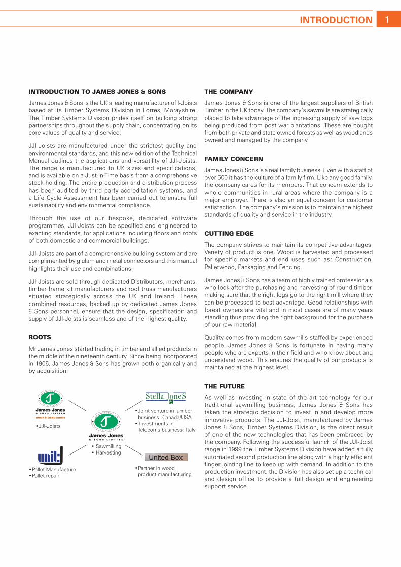
roots
Mr James Jones started trading in timber and allied products in the middle of the nineteenth century. Since being incorporated in 1905, James Jones & Sons has grown both organically and by acquisition.
the company
James Jones & Sons is one of the largest suppliers of British Timber in the UK today. The company’s sawmills are strategically placed to take advantage of the increasing supply of saw logs being produced from post war plantations. These are bought from both private and state owned forests as well as woodlands owned and managed by the company.
FamIly concern
James Jones & Sons is a real family business. Even with a staff of over 500 it has the culture of a family firm. Like any good family, the company cares for its members. That concern extends to whole communities in rural areas where the company is a major employer. There is also an equal concern for customer satisfaction. The company’s mission is to maintain the highest standards of quality and service in the industry.
cuttIng edge
The company strives to maintain its competitive advantages. Variety of product is one. Wood is harvested and processed for specific markets and end uses such as: Construction, Palletwood, Packaging and Fencing.
James Jones & Sons has a team of highly trained professionals who look after the purchasing and harvesting of round timber, making sure that the right logs go to the right mill where they can be processed to best advantage. Good relationships with forest owners are vital and in most cases are of many years standing thus providing the right background for the purchase of our raw material.
Quality comes from modern sawmills staffed by experienced people. James Jones & Sons is fortunate in having many people who are experts in their field and who know about and understand wood. This ensures the quality of our products is maintained at the highest level.
the Future
As well as investing in state of the art technology for our traditional sawmilling business, James Jones & Sons has taken the strategic decision to invest in and develop more innovative products. The JJI-Joist, manufactured by James Jones & Sons, Timber Systems Division, is the direct result of one of the new technologies that has been embraced by the company. Following the successful launch of the JJI-Joist range in 1999 the Timber Systems Division have added a fully automated second production line along with a highly efficient finger jointing line to keep up with demand. In addition to the production investment, the Division has also set up a technical and design office to provide a full design and engineering support service.
• Sawmilling• Harvesting
• Joint venture in lumber business: Canada/USA• Investments in Telecoms business: Italy
• Pallet Manufacture• Pallet repair
• Partner in wood product manufacturing
United Box
• JJI-Joists
2 The sYsTeM
the JJI-JoIst system
The JJI-Joist system relies on a unique combination of engineered products designed to compliment each other and deliver outstanding performance.
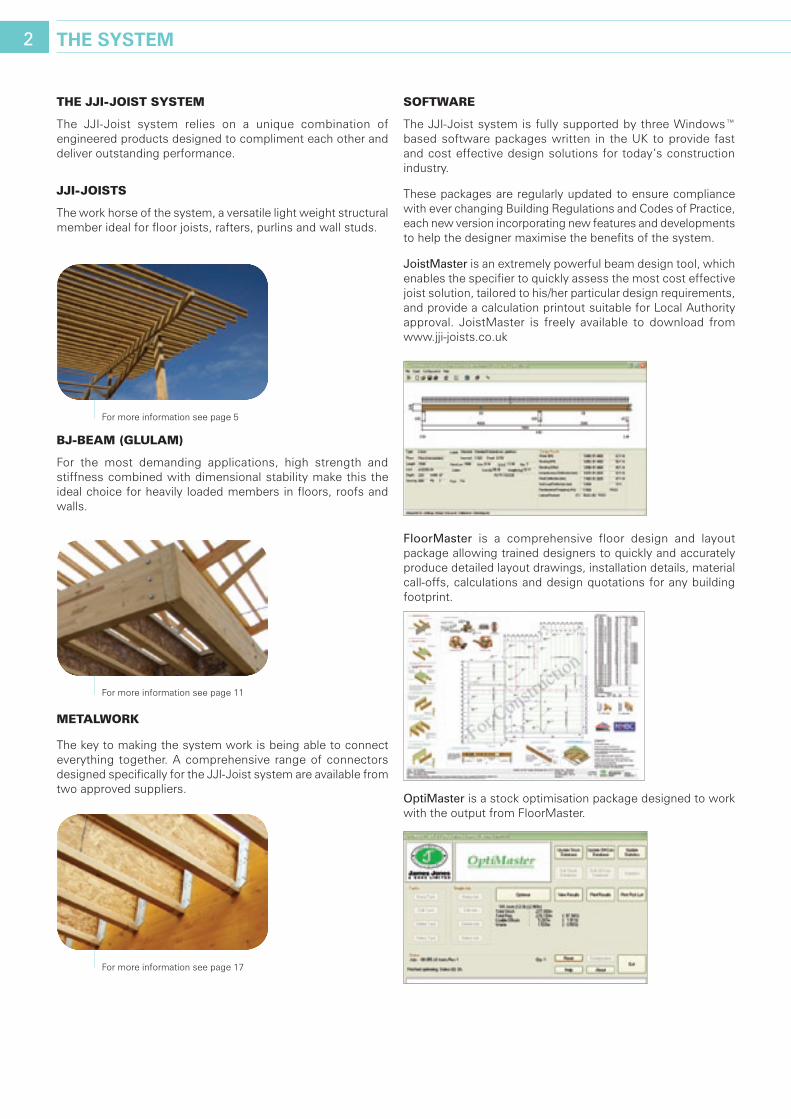
JJI-JoIsts
The work horse of the system, a versatile light weight structural member ideal for floor joists, rafters, purlins and wall studs.
BJ-Beam (glulam)
For the most demanding applications, high strength and stiffness combined with dimensional stability make this the ideal choice for heavily loaded members in floors, roofs and walls.
metalwork
The key to making the system work is being able to connect everything together. A comprehensive range of connectors designed specifically for the JJI-Joist system are available from two approved suppliers.
soFtware
The JJI-Joist system is fully supported by three Windows™ based software packages written in the UK to provide fast and cost effective design solutions for today’s construction industry.
These packages are regularly updated to ensure compliance with ever changing Building Regulations and Codes of Practice, each new version incorporating new features and developments to help the designer maximise the benefits of the system.
JoistMaster is an extremely powerful beam design tool, which enables the specifier to quickly assess the most cost effective joist solution, tailored to his/her particular design requirements, and provide a calculation printout suitable for Local Authority approval. JoistMaster is freely available to download from www.jji-joists.co.uk
floorMaster is a comprehensive floor design and layout package allowing trained designers to quickly and accurately produce detailed layout drawings, installation details, material call-offs, calculations and design quotations for any building footprint.
optiMaster is a stock optimisation package designed to work with the output from FloorMaster.
For more information see page 5
For more information see page 11
For more information see page 17

3General InForMaTIon
dIstrIButIon
The JJI-Joist system is available from a network of builders/ timber merchants and timber frame and engineered timber system manufacturers providing local, quality expertise.
These Distributors are trained to use our software and understand the correct use and specification of our products. This training is ongoing and ensures our Distributors have the skills required to provide an efficient, cost-effective, JJI-Joist solution.
Distributor details are available to download from www.jji-joists.co.uk
customer servIces and technIcal support
James Jones & Sons, Timber Systems Division has a highly trained team of Technical, Engineering and Sales personnel providing UK and Irish national coverage to ensure simple, safe and quick installation of JJI-Joist systems. A summary of the services offered is given below.
• PreandAfterSalesAssistance
• EngineeringSupport
• ProductTrainingCourses
• SoftwareandDesignTraining
• BuildingSiteTraining
• FullDesignandEngineeringService
approvals
JJI-Joists are an accepted building material within the construction industry thanks to third party certification from both the British Board of Agrément and BM trADA Certification.
BBA certification and BMTRADA Q-Mark are recognised by NhBC, Zurich, Local Authority Building Control and others.
James Jones & Sons are founder members of the UK Timber Frame Association (UKTFA) Engineered Wood Products Committee and were involved in the drafting of the Code of Practice for the Design of Engineered Wood Products which provides guidance on the design of structures using I-joists.
QualIty control and QualIty assurance
The success of a manufactured product is often determined by its quality. It is for this reason the James Jones & Sons, Timber Systems Division maintains a thorough Quality Assurance program which enables us to achieve our goal of producing a consistent and uniform product of exceptionally high standards. JJI-Joists are manufactured under a Quality Assurance scheme which complies with ISO 9001:2008 and CE marking.
research and development
The Timber Systems Division has an ongoing research and development program designed to find new applications for existing products and to improve the performance in current applications. In addition to this, production methods and technology are continuously reviewed and improved to maximise quality and efficiency.
BM TRADA
CERTIFICATE NUMBER EWP-0001
ENGINEERED WOOD PRODCUTS
James Smith 07500 016773 Lynford Chambers 07879 888216
Peter Barker 07977 283781
Mark Tilston 07977 283756
JJI-JOISTS UK STOCKISTS & TECHNICAL SUPPORT
JJI–Joist Distributor
Timber Frame Kit Supplier
General Support
01309 671111
Regional Support
Greshop Industrial Estate, Forres, Moray, IV36 1JJ
www.jji-joists.co.uk

4 enVIronMenTal InForMaTIon
envIronmental management
Environmental considerations are a very important factor in the production of JJI-Joists. Our certified ISO 14001:2004 Environmental Management System has enabled the company to target key areas to reduce the impacts of our activities on the environment.
The introduction of sustainable heating systems and the continuous commitment to waste minimisation, energy savings and recycling of materials used ensures the delivery of JJI-Joists with the smallest environmental footprint possible.The constant consideration of the environment in our current and future plans has shaped our purchasing policy to choose only those technologies that can prevent pollution and improve our environmental performance.
The high competence of our employees enables our environmental objectives to be implemented and exceeded every year. The support given by management ensures that a continual improvement culture in environmental performance is always present at the very centre of all our activities. As environmental considerations affect the whole JJI-Joist supply chain, we are engaged in continuous dialogue with our suppliers and distributors to minimise this impact. One result from these efforts has been the mutual decision to supply only timber from sustainable sources.
Therefore, our commitment to ISO 14001:2004 not only guarantees you compliance with all current and forthcoming legislation but delivers a JJI-Joist with excellent environmental credentials and minimal impacts throughout its life cycle.
chaIn oF custody
The UK Government policy on timber purchasing has stated that timber should only be purchased from legal and sustainable sources. Increasingly, both public and private sectors are encouraged to follow this policy.
Sustainable timber supply has always been integral to the manufacture of our engineered wood products. JJI-Joists meets this requirement as they can be specified as FSC Certified or PEFC Certified. These claims are independently verified through BM TRADA Forest Product certification scheme.
The Central Point of Expertise on Timber Procurement (CPET), the UK Government advisory committee for timber purchasing, has established the different options available for companies to prove that timber is legal and sustainable. In this way, compliance with an existing certification scheme approved by CPET is considered to be sufficient. Both FSC and PEFC schemes have been approved as a way to deliver legal and sustainable timber.
lIFe cycle
True sustainability can only be measured and improved upon by assessing all environmental impacts associated with the sourcing, transport and manufacture of that product (ie. from the forest to the end user).
JJI-Joists can help to mitigate climate change as timber acts as a carbon sink. Carbon dioxide (CO²) is absorbed by trees and used to create wood. This CO² is only released back into the environment when the joists come to the end of their lifetime. As only sustainable timber is used for the production of JJI-Joists, other trees are planted to replace harvested ones immediately, closing the CO² cycle and contributing to keep a constant or even increasing volume of CO² locked away from the atmosphere where it cannot contribute to climate change.
The continuous planning and research to minimise transport, purchase new formulation resins and use biomass as a way to substitute fossil fuels ensures that impacts throughout the life cycle of JJI-Joists are minimal.
These low impacts have been recognised by the current scheme created to quantify environmental impacts of products such as BRE environmental profiles. Scores for this scheme are used in the assessment process of 'The Code for Sustainable Homes' in England and Wales and 'Ecohomes' in Scotland. Timber I-joists such as JJI-Joists achieve the best scores in this scheme (A+) and therefore can help specifiers to achieve the Zero Carbon House level.
thermal perFormance
Other advantages of using JJI-Joists are their superior strength to weight ratio and readily available deep sections (up to 450mm) when compared with solid timber. In this way more insulation can be used within the building envelope and significant savings in heating can be achieved.
The thin web used in JJI-Joists contributes to minimise repeated thermal bridging in timber frame structures enabling JJI-Joists to achieve better U-values than solid timber. This property makes JJI-Joists ideal as a structural member in roofs and walls in low energy buildings.
The UK government has already expressed their preference for better insulated and airtight building envelopes as a way to reduce energy consumption. The adoption of insulated structures using JJI-Joists and designed according to principles such as Passivhaus can significantly reduce the energy requirements for heating and this approach will be essential to achieve a truly Zero Carbon House.
TT-COC 1503 & 1064 BMT-PEFC-0105
natural gas supply diesel
supply
water supply
co-products
electricity supply
emissionsto water
emissionsto land
emissionsto air
osb
Flanges
Glue
Packaging
5JJI-JoIsTs
IntroductIon
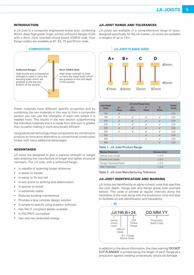
A JJI-Joist is a composite engineered timber joist, combining 45mm deep high-grade finger jointed softwood flanges (C24) with a 9mm thick oriented strand board (OSB/3) web. Four flange widths are available at 47, 63, 72 and 97mm wide.
These materials have different specific properties and by combining the two materials in this way to form a composite section you can use the strengths of each one where it is needed most. This results in the new section outperforming the individual materials that it is made from (the sum is greater than its parts) making it more structurally efficient.
Using advanced technology these components are combined to produce an innovative alternative to conventional construction timber with many additional advantages.
advantages
JJI-Joists are designed to give a superior strength to weight ratio enabling the manufacture of longer and lighter structural members. The JJI-Joist, with a softwood flange:
• Iscapableofspanninglongerdistances
• Iseasiertohandle
• Iseasiertofixandnail
• Islesspronetosplittinganddelamination
• Isquickertoinstall
• Isextremelystable
• Reducesbuildingmaintenance
• Providesalesscomplexdesignsolution
• Issimpletospecifyusingsuperiorsoftware
• HasPartEcompliantdetailsavailable
• IsFSC/PEFCaccredited
• Hasverylowembodiedenergy
JJI-JoIst range and tolerances
JJI-Joists are available in a comprehensive range of sizes, designed specifically for the UK market. JJI-Joists are available in lengths of up to 12m.
Joist depth(mm)
JJI-Joist Flange sizesTimberGradea+
47mmb+
63mmc
72mmd
97mm
145 3 C24
195 3 3 3 3 C24
220 3 3 3 3 C24
235 3 3 3 3 C24
245 3 3 3 3 C24
300 3 3 3 3 C24
350 3 3 C24
400 3 3 C24
450 3 C24
table 1. JJI-Joist Product range
Member dimension Tolerance (mm)
Overall Joist Length +/-3.0
Overall Joist Depth +/-2.0
Flange Thickness/Depth +/-2.0
Web Thickness +/-0.8
table 2. JJI-Joist Manufacturing tolerance
JJI-JoIst IdentIFIcatIon and markIng
JJI-Joists are identified by an alpha numeric code that specifies the joist depth, flange size and flange grade (see example below). This code is printed at regular intervals along the centreline of the web along with the production time and date to facilitate on-site identification and traceability.
In addition to the above information, the clear warning 'Do Not Cut fLANGES' is printed along the length of each flange as a precaution against creating unnecessary structural damage.
47mm 63mm 72mm 97mm
45mm
A+ B+ C D45mm
JJI-JoIsT FlanGe sIzes
Softwood flanges 9mm OSB/3 Web
High tensile and compressivestrength is used to carry thebending loads which aregreatest at the top and bottom of the section
High shear strength is used to carry the shear loads whichare greatest at the mid depthof the section
coMPosITIon
JJI195 B+24
JamesJonesI-Joist
195mmDeep
‘B+’ Flange63mm Wide
C24TimberFlange
DD.MM.YY
ProductionBatch Code
Id
6 JJI-JoIsTs
JJI-JoIst propertIes
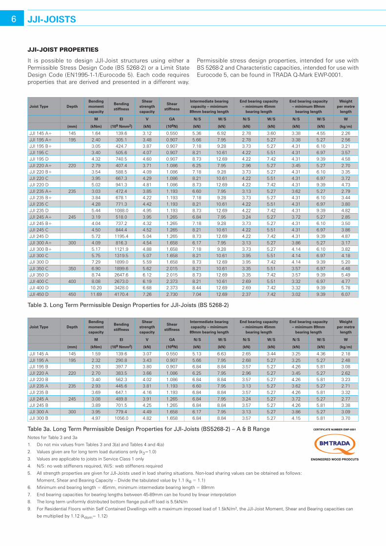
It is possible to design JJI-Joist structures using either a Permissible Stress Design Code (BS 5268-2) or a Limit State Design Code (EN1995-1-1/Eurocode 5). Each code requires properties that are derived and presented in a different way.
Joist Type depth bending moment capacity
bending stiffness
shear strength capacity
shear stiffness
Intermediate bearing capacity – minimum
89mm bearing length
end bearing capacity – minimum 45mm
bearing length
end bearing capacity – minimum 89mm
bearing length
weight per metre
length
M eI V Ga n/s w/s n/s w/s n/s w/s w
(mm) (knm) (109 nmm2) (kn) (106n) (kn) (kn) (kn) (kn) (kn) (kn) (kg/m)
JJI 145 A+ 145 1.64 139.6 3.12 0.550 5.36 6.92 2.78 3.60 3.38 4.55 2.26JJI 195 A+ 195 2.40 305.1 3.48 0.907 5.66 7.95 2.78 5.27 3.38 5.27 2.56JJI 195 B+ 3.05 424.7 3.87 0.907 7.18 9.28 3.73 5.27 4.31 6.10 3.21JJI 195 C 3.40 505.6 4.07 0.907 8.21 10.61 4.22 5.51 4.31 6.97 3.57JJI 195 D 4.32 740.5 4.60 0.907 8.73 12.69 4.22 7.42 4.31 9.39 4.58JJI 220 A+ 220 2.79 407.4 3.71 1.086 6.25 7.95 2.96 5.27 3.45 5.27 2.70JJI 220 B+ 3.54 588.5 4.09 1.086 7.18 9.28 3.73 5.27 4.31 6.10 3.35JJI 220 C 3.95 667.3 4.29 1.086 8.21 10.61 4.22 5.51 4.31 6.97 3.72JJI 220 D 5.02 941.3 4.81 1.086 8.73 12.69 4.22 7.42 4.31 9.39 4.73JJI 235 A+ 235 3.03 472.4 3.85 1.193 6.60 7.95 3.13 5.27 3.62 5.27 2.79JJI 235 B+ 3.84 678.1 4.22 1.193 7.18 9.28 3.73 5.27 4.31 6.10 3.44JJI 235 C 4.28 771.3 4.42 1.193 8.21 10.61 4.22 5.51 4.31 6.97 3.80JJI 235 D 5.44 1088.0 4.95 1.193 8.73 12.69 4.22 7.42 4.31 9.39 4.82JJI 245 A+ 245 3.19 518.0 3.95 1.265 6.84 7.95 3.24 5.27 3.72 5.27 2.85JJI 245 B+ 4.04 737.2 4.32 1.265 7.18 9.28 3.73 5.27 4.31 6.10 3.50JJI 245 C 4.50 844.4 4.52 1.265 8.21 10.61 4.22 5.51 4.31 6.97 3.86JJI 245 D 5.72 1195.4 5.04 1.265 8.73 12.69 4.22 7.42 4.31 9.39 4.87JJI 300 A+ 300 4.09 816.3 4.54 1.658 6.17 7.95 3.13 5.27 3.86 5.27 3.17JJI 300 B+ 5.17 1121.9 4.88 1.658 7.18 9.28 3.73 5.27 4.14 6.10 3.82JJI 300 C 5.75 1319.5 5.07 1.658 8.21 10.61 3.95 5.51 4.14 6.97 4.18JJI 300 D 7.29 1899.0 5.59 1.658 8.73 12.69 3.95 7.42 4.14 9.39 5.20JJI 350 C 350 6.90 1899.6 5.62 2.015 8.21 10.61 3.35 5.51 3.57 6.97 4.48JJI 350 D 8.74 2647.6 6.12 2.015 8.73 12.69 3.35 7.42 3.57 9.39 5.49JJI 400 C 400 8.08 2673.0 6.19 2.373 8.21 10.61 2.69 5.51 3.32 6.97 4.77JJI 400 D 10.20 3428.0 6.68 2.373 8.44 12.69 2.69 7.42 3.32 9.39 5.78JJI 450 D 450 11.69 4170.4 7.26 2.730 7.04 12.69 2.37 7.42 3.02 9.39 6.07
table 3. Long term Permissible Design Properties for JJI-Joists (BS 5268-2)
Joist Type depthbending moment capacity
bending stiffness
shear strength capacity
shear stiffness
Intermediate bearing capacity – minimum
89mm bearing length
end bearing capacity – minimum 45mm
bearing length
end bearing capacity – minimum 89mm
bearing length
weight per metre
length
M eI V Ga n/s w/s n/s w/s n/s w/s w
(mm) (knm) (109 nmm2) (kn) (106n) (kn) (kn) (kn) (kn) (kn) (kn) (kg/m)
JJI 145 A 145 1.59 139.6 3.07 0.550 5.13 6.63 2.65 3.44 3.25 4.36 2.18JJI 195 A 195 2.32 290.8 3.43 0.907 5.66 7.95 2.68 5.27 3.25 5.27 2.48JJI 195 B 2.93 397.7 3.80 0.907 6.84 8.84 3.57 5.27 4.26 5.81 3.08JJI 220 A 220 2.70 383.5 3.66 1.086 6.25 7.95 2.96 5.27 3.45 5.27 2.62JJI 220 B 3.40 562.3 4.02 1.086 6.84 8.84 3.57 5.27 4.26 5.81 3.23JJI 235 A 235 2.93 445.6 3.81 1.193 6.60 7.95 3.13 5.27 3.62 5.27 2.71JJI 235 B 3.69 647.1 4.16 1.193 6.84 8.84 3.57 5.27 4.26 5.81 3.32JJI 245 A 245 3.08 489.8 3.91 1.265 6.84 7.95 3.24 5.27 3.72 5.27 2.77JJI 245 B 3.89 701.5 4.25 1.265 6.84 8.84 3.57 5.27 4.26 5.81 3.38JJI 300 A 300 3.95 779.4 4.49 1.658 6.17 7.95 3.13 5.27 3.86 5.27 3.09JJI 300 B 4.97 1056.0 4.82 1.658 6.84 8.84 3.57 5.27 4.15 5.81 3.70
table 3a. Long term Permissible Design Properties for JJI-Joists (BS5268-2) – A & B rangeNotes for Table 3 and 3a
1. Do not mix values from Tables 3 and 3(a) and Tables 4 and 4(a)
2. Values given are for long term load durations only (k3=1.0)
3. Values are applicable to joists in Service Class 1 only
4. N/S: no web stiffeners required, W/S: web stiffeners required
5. All strength properties are given for JJI-Joists used in load sharing situations. Non-load sharing values can be obtained as follows:
Moment, Shear and Bearing Capacity – Divide the tabulated value by 1.1 (k8 = 1.1)
6. Minimum end bearing length = 45mm, minimum intermediate bearing length = 89mm
7. End bearing capacities for bearing lengths between 45-89mm can be found by linear interpolation
8. The long term uniformly distributed bottom flange pull-off load is 5.5kN/m
9. For Residential Floors within Self Contained Dwellings with a maximum imposed load of 1.5kN/m2, the JJI-Joist Moment, Shear and Bearing capacities can
be multiplied by 1.12 (kdom= 1.12)
Permissible stress design properties, intended for use with BS 5268-2 and Characteristic capacities, intended for use with Eurocode 5, can be found in TRADA Q-Mark EWP-0001.
BM TRADA
CERTIFICATE NUMBER EWP-0001
ENGINEERED WOOD PRODCUTS
7JJI-JoIsTs
Joist Type depth bending moment capacity
bending stiffness
shear strength capacity
shear stiffness
Intermediate bearing capacity – minimum
89mm bearing length
end bearing capacity – minimum 45mm
bearing length
end bearing capacity – minimum 89mm
bearing length
weight per metre
length
M eI V Ga n/s w/s n/s w/s n/s w/s w(mm) (knm) (109 nmm2) (kn) (106n) (kn) (kn) (kn) (kn) (kn) (kn) (kg/m)
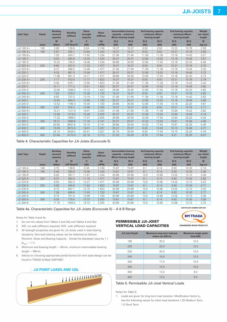
JJI 145 A+ 145 3.89 139.6 9.54 0.748 16.37 16.37 8.50 8.50 10.33 10.76 2.26JJI 195 A+ 195 5.67 305.1 10.64 1.234 16.37 16.37 8.50 8.50 10.31 10.76 2.56JJI 195 B+ 7.20 424.7 11.82 1.234 21.94 21.94 11.39 11.39 13.16 14.42 3.21JJI 195 C 8.03 505.6 12.44 1.234 25.07 25.07 12.90 13.02 13.16 16.48 3.57JJI 195 D 10.22 740.5 14.06 1.234 26.66 30.00 12.90 17.54 13.16 22.20 4.58JJI 220 A+ 220 6.60 407.4 11.33 1.477 16.37 16.37 8.50 8.50 10.31 10.76 2.70JJI 220 B+ 8.37 588.5 12.48 1.477 21.94 21.94 11.39 11.39 13.16 14.42 3.35JJI 220 C 9.32 667.3 13.09 1.477 25.07 25.07 12.90 13.02 13.16 16.48 3.72JJI 220 D 11.86 941.3 14.71 1.477 26.66 30.00 12.90 17.54 13.16 22.20 4.73JJI 235 A+ 235 7.17 472.4 11.77 1.623 16.37 16.37 8.50 8.50 10.31 10.76 2.79JJI 235 B+ 9.08 678.1 12.90 1.623 21.94 21.94 11.39 11.39 13.16 14.42 3.44JJI 235 C 10.11 771.3 13.51 1.623 25.07 25.07 12.90 13.02 13.16 16.48 3.80JJI 235 D 12.85 1088.0 15.12 1.623 26.66 30.00 12.90 17.54 13.16 22.20 4.82JJI 245 A+ 245 7.54 518.0 12.08 1.720 16.37 16.37 8.50 8.50 10.31 10.76 2.85JJI 245 B+ 9.55 737.2 13.19 1.720 21.94 21.94 11.39 11.39 13.16 14.42 3.50JJI 245 C 10.64 844.4 13.80 1.720 25.07 25.07 12.90 13.02 13.16 16.48 3.86JJI 245 D 13.52 1195.4 15.40 1.720 26.66 30.00 12.90 17.54 13.16 22.20 4.87JJI 300 A+ 300 9.67 816.3 13.86 2.255 16.37 16.37 8.50 8.50 10.31 10.76 3.17JJI 300 B+ 12.21 1121.9 14.91 2.255 21.94 21.94 11.39 11.39 12.64 14.42 3.82JJI 300 C 13.58 1319.5 15.49 2.255 25.07 25.07 12.08 13.02 12.64 16.48 4.18JJI 300 D 17.22 1899.0 17.07 2.255 26.66 30.00 12.08 17.54 12.64 22.20 5.20JJI 350 C 350 16.31 1899.6 17.16 2.741 25.07 25.07 10.22 13.02 10.91 16.48 4.48JJI 350 D 20.65 2647.6 18.70 2.741 26.66 30.00 10.22 17.54 10.91 22.20 5.49JJI 400 C 400 19.09 2673.0 18.91 3.227 25.07 25.07 8.20 13.02 10.15 16.48 4.77JJI 400 D 24.12 3428.0 20.41 3.227 25.79 30.00 8.20 17.54 10.15 22.20 5.78JJI 450 D 450 27.64 4170.4 22.18 3.713 21.50 30.00 6.79 17.54 9.21 22.20 6.07
table 4. Characteristic Capacities for JJI-Joists (Eurocode 5)
Joist Type depthbending moment capacity
bending stiffness
shear strength capacity
shear stiffness
Intermediate bearing capacity – minimum
89mm bearing length
end bearing capacity – minimum 45mm
bearing length
end bearing capacity – minimum 89mm
bearing length
weight per metre
length
M eI V Ga n/s w/s n/s w/s n/s w/s w(mm) (knm) (109 nmm2) (kn) (106n) (kn) (kn) (kn) (kn) (kn) (kn) (kg/m)
JJI 145 A 145 3.75 139.6 9.38 0.748 15.67 15.67 8.1 8.14 9.92 10.30 2.18JJI 195 A 195 5.48 290.8 10.49 1.234 15.67 15.67 8.1 8.14 9.92 10.30 2.48JJI 195 B 6.92 397.7 11.61 1.234 20.89 20.89 10.9 10.85 13.02 13.73 3.08JJI 220 A 220 6.37 383.5 11.18 1.477 15.67 15.67 8.1 8.14 9.92 10.30 2.62JJI 220 B 8.05 562.3 12.27 1.477 20.89 20.89 10.9 10.85 13.02 13.73 3.23JJI 235 A 235 6.92 445.6 11.62 1.623 15.67 15.67 8.1 8.14 9.92 10.30 2.71JJI 235 B 8.73 647.1 12.70 1.623 20.89 20.89 10.9 10.85 13.02 13.73 3.32JJI 245 A 245 7.28 489.8 11.93 1.720 15.67 15.67 8.1 8.14 9.92 10.30 2.77JJI 245 B 9.19 701.5 12.99 1.720 20.89 20.89 10.9 10.85 13.02 13.73 3.38JJI 300 A 300 9.34 779.4 13.73 2.255 15.67 15.67 8.1 8.14 9.92 10.30 3.09JJI 300 B 11.75 1056.0 14.72 2.255 20.89 20.89 10.9 10.85 12.66 13.73 3.70
table 4a. Characteristic Capacities for JJI-Joists (Eurocode 5) – A & B range
JJI PoInT loads and udl
Notes for Table 4 and 4a:
1. Do not mix values from Tables 3 and 3(a) and Tables 4 and 4(a)
2. N/S: no web stiffeners required, W/S: web stiffeners required
3. All strength properties are given for JJI-Joists used in load sharing
situations. Non-load sharing values can be obtained as follows:
Moment, Shear and Bearing Capacity – Divide the tabulated value by 1.1
(ksys = 1.1)
4. Minimum end bearing length = 45mm, minimum intermediate bearing
length = 89mm
5. Advice on choosing appropriate partial factors for limit state design can be
found in TRADA Q-Mark EWP-0001
permIssIBle JJI-JoIst vertIcal load capacItIes
JJI Joist depth Maximum long term load per metre run (kn/m)
Maximum single point load (kn)
195 25.0 12.0
220 20.0 12.0
235 20.0 12.0
245 19.0 12.0
300 17.0 10.0
350 15.0 10.0
400 13.0 8.0
450 12.0 8.0
table 5. Permissible JJI-Joist Vertical Loads
Notes for Table 5:
1. Loads are given for long term load duration. Modification factor k3
has the following values for other load durations 1.25 Medium Term,
1.5 Short Term
BM TRADA
CERTIFICATE NUMBER EWP-0001
ENGINEERED WOOD PRODCUTS
8 serVIce holes In JJI-JoIsTs
JJI-JoIst hole InstallatIon guIde: cIrcular, sQuare and rectangular holes
Service holes MuSt Not BE Cut in the JJI-Joist flange.
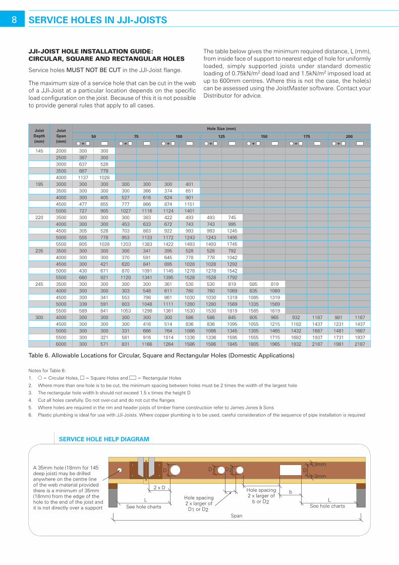
The maximum size of a service hole that can be cut in the web of a JJI-Joist at a particular location depends on the specific load configuration on the joist. Because of this it is not possible to provide general rules that apply to all cases.
The table below gives the minimum required distance, L (mm), from inside face of support to nearest edge of hole for uniformly loaded, simply supported joists under standard domestic loading of 0.75kN/m2 dead load and 1.5kN/m2 imposed load at up to 600mm centres. Where this is not the case, the hole(s) can be assessed using the JoistMaster software. Contact your Distributor for advice.
Joist depth(mm)
Joist span(mm)
hole size (mm)
50 75 100 125 150 175 200
+ + + + + + +
145 2000 300 3002500 387 3003000 637 5283500 887 7784000 1137 1028
195 3000 300 300 300 300 300 4013500 300 300 300 366 374 6514000 300 405 527 616 624 9014500 477 655 777 866 874 11515000 727 905 1027 1116 1124 1401
220 3500 300 300 300 383 422 493 493 7454000 300 300 453 633 672 743 743 9954500 305 528 703 883 922 993 993 12455000 555 778 953 1133 1172 1243 1243 14955500 805 1028 1203 1383 1422 1493 1493 1745
235 3500 300 300 300 341 395 528 528 7924000 300 300 370 591 645 778 778 10424500 300 421 620 841 895 1028 1028 12925000 430 671 870 1091 1145 1278 1278 15425500 680 921 1120 1341 1395 1528 1528 1792
245 3500 300 300 300 300 361 530 530 819 585 8194000 300 300 303 548 611 780 780 1069 835 10694500 300 341 553 798 861 1030 1030 1319 1085 13195000 339 591 803 1048 1111 1280 1280 1569 1335 15695500 589 841 1053 1298 1361 1530 1530 1819 1585 1819
300 4000 300 300 300 300 300 586 586 845 805 965 932 1187 981 11874500 300 300 300 416 514 836 836 1095 1055 1215 1182 1437 1231 14375000 300 300 331 666 764 1086 1086 1345 1305 1465 1432 1687 1481 16875500 300 321 581 916 1014 1336 1336 1595 1555 1715 1682 1937 1731 19376000 300 571 831 1166 1264 1586 1586 1845 1805 1965 1932 2187 1981 2187
table 6. Allowable Locations for Circular, Square and rectangular holes (Domestic Applications)
Notes for Table 6:
1. = Circular Holes, = Square Holes and = Rectangular Holes
2. Where more than one hole is to be cut, the minimum spacing between holes must be 2 times the width of the largest hole
3. The rectangular hole width b should not exceed 1.5 x times the height D
4. Cut all holes carefully. Do not over-cut and do not cut the flanges
5. Where holes are required in the rim and header joists of timber frame construction refer to James Jones & Sons
6. Plastic plumbing is ideal for use with JJI-Joists. Where copper plumbing is to be used, careful consideration of the sequence of pipe installation is required
A 35mm hole (18mm for 145 deep joist) may be drilledanywhere on the centre lineof the web material providedthere is a minimum of 35mm(18mm) from the edge of the hole to the end of the joist and it is not directly over a support
LSee hole charts
LSee hole charts
2 x D b
D D1 D2 D3mm
3mm
Hole spacing2 x larger ofD1 or D2
Span
Hole spacing2 x larger of
b or D2
serVIce hole helP dIaGraM
9FIre and durabIlITY
FIre resIstance
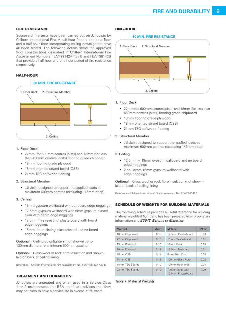
Successful fire tests have been carried out on JJI-Joists by Chiltern International Fire. A half-hour floor, a one-hour floor and a half-hour floor incorporating ceiling downlighters have all been tested. The following details show the approved floor constructions described in Chiltern International Fire Assessment Numbers FEA/F99142A Rev B and FEA/F99142B that provide a half-hour and one hour period of fire resistance respectively.
halF-hour
1. floor Deck
• 22mm(for600mmcentresjoists)and18mm(forlessthan 450mm centres joists) flooring grade chipboard
• 18mmflooringgradeplywood
• 18mmorientedstrandboard(OSB)
• 21mmT&Gsoftwoodflooring
2. Structural Member
• JJI-Joistdesignedtosupporttheappliedloadsatmaximum 600mm centres (excluding 145mm deep)
3. Ceiling
• 15mmgypsumwallboardwithoutboardedgenoggings
• 12.5mmgypsumwallboardwith5mmgypsumplasterskim with board edge noggings
• 12.5mm‘fireresisting’plasterboardwithboard edge noggings
• 15mm‘fireresisting’plasterboardandnoboard edge noggings
optional – Ceiling downlighters (not shown) up to 130mm diameter at minimum 500mm spacing
optional – Glass wool or rock fibre insulation (not shown) laid on back of ceiling lining
Reference – Chiltern International Fire assessment No. FEA/F99142A Rev B
treatment and duraBIlIty
JJI-Joists are untreated and when used in a Service Class 1 or 2 environment, the BBA certificate advises that they may be taken to have a service life in excess of 60 years.
one-hour
1. floor Deck
• 22mm(for600mmcentresjoists)and18mm(forlessthan450mm centres joists) flooring grade chipboard
• 18mmflooringgradeplywood
• 18mmorientedstrandboard(OSB)
• 21mmT&Gsoftwoodflooring
2. Structural Member
• JJI-Joistdesignedtosupporttheappliedloadsatmaximum 600mm centres (excluding 145mm deep)
3. Ceiling
• 12.5mm+19mmgypsumwallboardandnoboardedge noggings
• 2no.layers15mmgypsumwallboardwith edge noggings
optional – Glass wool or rock fibre insulation (not shown) laid on back of ceiling lining
Reference – Chiltern International Fire assessment No. FEA/F99142B
schedule oF weIghts For BuIldIng materIals
The following schedule provides a useful reference for building material weights (kN/m2) and has been prepared from proprietary information and BS648 Weights of Materials.
Material kN/m2 Material kN/m2
18mm Chipboard 0.13 12.5mm Plasterboard 0.09
22mm Chipboard 0.16 15mm Plasterboard 0.11
15mm Plywood 0.10 19mm Plank 0.15
19mm Plywood 0.12 12.5mm Fireboard 0.11
15mm OSB 0.11 5mm Skim Coat 0.05
18mm OSB 0.13 100mm Glass Fibre 0.02
18mm T&G Boards 0.10 100mm Rock Wool 0.04
22mm T&G Boards 0.12 Timber Studs with 12.5mm Plasterboard
0.29
table 7. Material Weights
1. Floor Deck 2. Structural Member
3. Ceiling
30 MIn. FIre resIsTance
1. Floor Deck 2. Structural Member
3. Ceiling
60 MIn. FIre resIsTance
compartment Floor
40mm screed system www.screedflo.co.uk
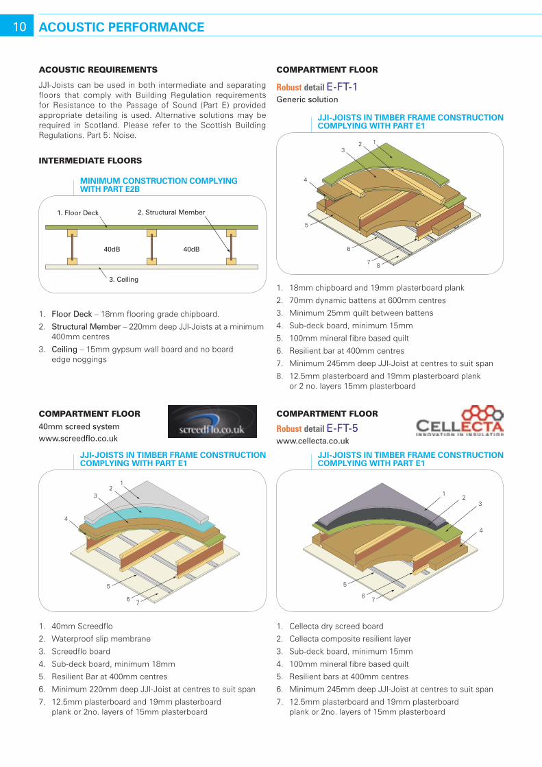
10 acousTIc PerForMance
compartment Floor
Robust detail E-ft-1 Generic solution
1. 18mm chipboard and 19mm plasterboard plank
2. 70mm dynamic battens at 600mm centres
3. Minimum 25mm quilt between battens
4. Sub-deck board, minimum 15mm
5. 100mm mineral fibre based quilt
6. Resilient bar at 400mm centres
7. Minimum 245mm deep JJI-Joist at centres to suit span
8. 12.5mm plasterboard and 19mm plasterboard plank or 2 no. layers 15mm plasterboard
compartment Floor
Robust detail E-ft-5 www.cellecta.co.uk
acoustIc reQuIrements
JJI-Joists can be used in both intermediate and separating floors that comply with Building Regulation requirements for Resistance to the Passage of Sound (Part E) provided appropriate detailing is used. Alternative solutions may be required in Scotland. Please refer to the Scottish Building Regulations. Part 5: Noise.
IntermedIate Floors
1. floor Deck – 18mm flooring grade chipboard.
2. Structural Member – 220mm deep JJI-Joists at a minimum 400mm centres
3. Ceiling – 15mm gypsum wall board and no board edge noggings
123
4
5
6
78
JJI-JoIsTs In TIMber FraMe consTrucTIon coMPlYInG wITh ParT e1
12
3
5
67
4
JJI-JoIsTs In TIMber FraMe consTrucTIon coMPlYInG wITh ParT e1
4
5
67
12
3
JJI-JoIsTs In TIMber FraMe consTrucTIon coMPlYInG wITh ParT e1
1. Floor Deck 2. Structural Member
3. Ceiling
40dB 40dB
MInIMuM consTrucTIon coMPlYInG wITh ParT e2b
1. 40mm Screedflo
2. Waterproof slip membrane
3. Screedflo board
4. Sub-deck board, minimum 18mm
5. Resilient Bar at 400mm centres
6. Minimum 220mm deep JJI-Joist at centres to suit span
7. 12.5mm plasterboard and 19mm plasterboard plank or 2no. layers of 15mm plasterboard
1. Cellecta dry screed board
2. Cellecta composite resilient layer
3. Sub-deck board, minimum 15mm
4. 100mm mineral fibre based quilt
5. Resilient bars at 400mm centres
6. Minimum 245mm deep JJI-Joist at centres to suit span
7. 12.5mm plasterboard and 19mm plasterboard plank or 2no. layers of 15mm plasterboard
11bJ-beaM (GlulaM)
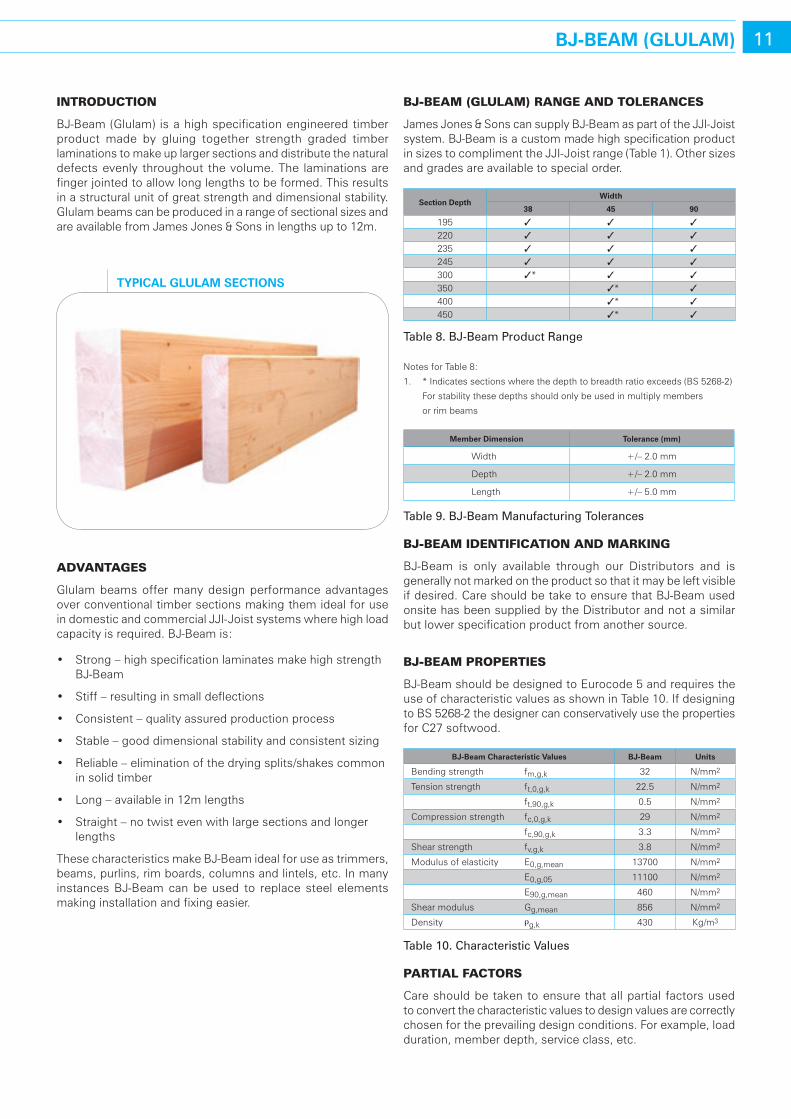
IntroductIon
BJ-Beam (Glulam) is a high specification engineered timber product made by gluing together strength graded timber laminations to make up larger sections and distribute the natural defects evenly throughout the volume. The laminations are finger jointed to allow long lengths to be formed. This results in a structural unit of great strength and dimensional stability. Glulam beams can be produced in a range of sectional sizes and are available from James Jones & Sons in lengths up to 12m.
advantages
Glulam beams offer many design performance advantages over conventional timber sections making them ideal for use in domestic and commercial JJI-Joist systems where high load capacity is required. BJ-Beam is:
• Strong–highspecificationlaminatesmakehighstrengthBJ-Beam
• Stiff–resultinginsmalldeflections
• Consistent–qualityassuredproductionprocess
• Stable–gooddimensionalstabilityandconsistentsizing
• Reliable–eliminationofthedryingsplits/shakescommonin solid timber
• Long–availablein12mlengths
• Straight–notwistevenwithlargesectionsandlongerlengths
These characteristics make BJ-Beam ideal for use as trimmers, beams, purlins, rim boards, columns and lintels, etc. In many instances BJ-Beam can be used to replace steel elements making installation and fixing easier.
BJ-Beam (glulam) range and tolerances
James Jones & Sons can supply BJ-Beam as part of the JJI-Joist system. BJ-Beam is a custom made high specification product in sizes to compliment the JJI-Joist range (Table 1). Other sizes and grades are available to special order.
section depthwidth
38 45 90
195 3 3 3
220 3 3 3
235 3 3 3
245 3 3 3
300 3* 3 3
350 3* 3
400 3* 3
450 3* 3
table 8. BJ-Beam Product range
Notes for Table 8:
1. * Indicates sections where the depth to breadth ratio exceeds (BS 5268-2)
For stability these depths should only be used in multiply members
or rim beams
Member dimension Tolerance (mm)
Width +/– 2.0 mm
Depth +/– 2.0 mm
Length +/– 5.0 mm
table 9. BJ-Beam Manufacturing tolerances
BJ-Beam IdentIFIcatIon and markIng
BJ-Beam is only available through our Distributors and is generally not marked on the product so that it may be left visible if desired. Care should be take to ensure that BJ-Beam used onsite has been supplied by the Distributor and not a similar but lower specification product from another source.
BJ-Beam propertIes
BJ-Beam should be designed to Eurocode 5 and requires the use of characteristic values as shown in Table 10. If designing to BS 5268-2 the designer can conservatively use the properties for C27 softwood.
bJ-beam characteristic Values bJ-beam units
Bending strength fm,g,k 32 N/mm2
Tension strength ft,0,g,k 22.5 N/mm2
ft,90,g,k 0.5 N/mm2
Compression strength fc,0,g,k 29 N/mm2
fc,90,g,k 3.3 N/mm2
Shear strength fv,g,k 3.8 N/mm2
Modulus of elasticity E0,g,mean 13700 N/mm2
E0,g,05 11100 N/mm2
E90,g,mean 460 N/mm2
Shear modulus Gg,mean 856 N/mm2
Density rg,k 430 Kg/m3
table 10. Characteristic Values
partIal Factors
Care should be taken to ensure that all partial factors used to convert the characteristic values to design values are correctly chosen for the prevailing design conditions. For example, load duration, member depth, service class, etc.
TYPIcal GlulaM secTIons
duratIon oF load
load duration class
service class Permanent long term Medium
termshort term Instantaneous
1 0.60 0.70 0.80 0.90 1.10
2 0.60 0.70 0.80 0.90 1.10
3 0.50 0.55 0.65 0.70 0.90
table 11. kmod for BJ-Beam design
materIal
The material modification factor can be taken as gM = 1.25.
servIce class
service class kdef
1 0.602 0.803 2.00
table 12. kdef for BJ-Beam design
To assist designers who are not familiar with Eurocode 5, Table 13 has been prepared by applying the appropriate factors to the characteristic values of BJ-Beam for a domestic floor application.
12 bJ-beaM (GlulaM)
width (mm)
depth (mm)
area (mm2) weight (kg/m)
section Modulus
z (105mm3)
Moment of Inertia
I (107mm4)
Flexural rigidity
eI (109 nmm2)
shear rigidity Ga (106 n)
d/w (–)
depthFactor
kh (–)
Moment capacity
(knm) shear
capacity (kn)
38 195 7410 3.71 2.41 2.35 322 6.30 5.1 1.10 3.62 8.01220 8360 4.18 3.07 3.37 462 7.11 5.8 1.10 4.60 9.04235 8930 4.47 3.50 4.11 563 7.59 6.2 1.10 5.24 9.65245 9310 4.66 3.80 4.66 638 7.91 6.4 1.09 5.68 10.06300 11400 5.70 5.70 8.55 1171 9.69 7.9 1.07 8.34 12.32
45 195 8775 4.39 2.85 2.78 381 7.46 4.3 1.10 4.28 9.48220 9900 4.95 3.63 3.99 547 8.42 4.9 1.10 5.45 10.70235 10575 5.29 4.14 4.87 667 8.99 5.2 1.10 6.21 11.43245 11025 5.51 4.50 5.51 756 9.37 5.4 1.09 6.72 11.92300 13500 6.75 6.75 10.13 1387 11.48 6.7 1.07 9.88 14.59350 15750 7.88 9.19 16.08 2203 13.39 7.8 1.06 13.24 17.02400 18000 9.00 12.00 24.00 3288 15.30 8.9 1.04 17.06 19.46450 20250 10.13 15.19 34.17 4682 17.21 10.0 1.03 21.34 21.89
90 195 17550 8.78 5.70 5.56 762 14.92 2.2 1.10 8.57 18.97220 19800 9.90 7.26 7.99 1094 16.83 2.4 1.10 10.90 21.40235 21150 10.58 8.28 9.73 1333 17.98 2.6 1.10 12.42 22.86245 22050 11.03 9.00 11.03 1511 18.74 2.7 1.09 13.44 23.83300 27000 13.50 13.50 20.25 2774 22.95 3.3 1.07 19.75 29.18350 31500 15.75 18.38 32.16 4405 26.78 3.9 1.06 26.48 34.05400 36000 18.00 24.00 48.00 6576 30.60 4.4 1.04 34.12 38.91450 40500 20.25 30.38 68.34 9363 34.43 5.0 1.03 42.68 43.78
table 13. BJ-Beam Design Values for Domestic flooring Applications
Notes for Table 13:
1. The moment and shear capacities are applicable for domestic floor applications only
2. Strength modification factor kmod = 0.8
3. Partial material factor gM = 1.25
4. Partial load factor gF = 1.5
5. Depth factor = (600/h)0.1
6. Larger section properties are available upon request
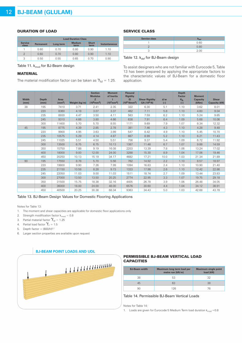
bJ-beaM PoInT loads and udlpermIssIBle BJ-Beam vertIcal load capacItIes
bJ-beam width Maximum long term load per metre run (kn/m)
Maximum single point load (kn)
38 53 32
45 63 38
90 126 76
table 14. Permissible BJ-Beam Vertical Loads
Notes for Table 14:
1. Loads are given for Eurocode 5 Medium Term load duration kmod =0.8
13bJ-beaM (GlulaM)
storage on sIte
BJ-Beam will typically arrive on site with a moisture content between 10% and 15%, and will achieve a moisture content of approximately 12% when installed in Service Class 1 conditions.
BJ-Beam should be stored clear of the ground on a flat level surface and protected from the weather.
Once installed, if the structure will not be weather tight for a prolonged period of time, the BJ-Beam should be protected from the weather to avoid excessive changes in moisture content, and associated dimensional changes.
treatment and duraBIlIty
BJ-Beam is untreated. When used in a Service Class 1 or 2 environment it will have a natural durability comparable to that of solid timber.
Following discussions with the NHBC it has been confirmed that when used as a rim beam in timber frame construction and protected by a layer of sheathing and breather paper, no additional preservative treatment is required.
Prior to preservative treatment advice should be sought from the manufacturer.
FIre resIstance
For the purpose of calculating the fire resistance of BJ-Beam members, a charring rate of 0.66mm per minute should be used.
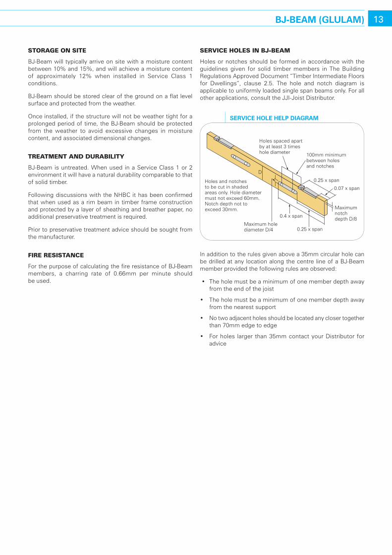
servIce holes In BJ-Beam
Holes or notches should be formed in accordance with the guidelines given for solid timber members in The Building Regulations Approved Document “Timber Intermediate Floors for Dwellings”, clause 2.5. The hole and notch diagram is applicable to uniformly loaded single span beams only. For all other applications, consult the JJI-Joist Distributor.
In addition to the rules given above a 35mm circular hole can be drilled at any location along the centre line of a BJ-Beam member provided the following rules are observed:
• Theholemustbeaminimumofonememberdepthawayfrom the end of the joist
• Theholemustbeaminimumofonememberdepthawayfrom the nearest support
• Notwoadjacentholesshouldbelocatedanyclosertogetherthan 70mm edge to edge
• Forholes largerthan35mmcontactyourDistributorforadvice
Holes spaced apart by at least 3 times hole diameter 100mm minimum
between holes and notches
0.25 x span
0.07 x span
Maximumnotchdepth D/8
Maximum holediameter D/4
Holes and notches to be cut in shaded areas only. Hole diameter must not exceed 60mm. Notch depth not to exceed 30mm.
D
0.25 x span
0.4 x span
serVIce hole helP dIaGraM
FIxIng oF multIply BJ-Beam memBers
Multiply BJ-Beam members can be fixed together using nails, screws or bolts depending on availability and preference.
Screws – Where possible, James Jones & Sons recommend the use of large diameter self tapping screws in preference to nails or bolts. The following products can be supplied by the approved JJI-Joist metalwork suppliers.
• Cullen Building Products LedgerLok @ Ø5.8mm
• SimpsonStrong-TieSDSscrew@Ø6.15mm
For details of the available screw sizes and advice on how they should be used please refer to the relevant metalwork manufacturer’s technical literature (see page 17 for contact details).
For cases where large diameter self tapping screws are not available this section provides some standard nailing and bolting details for uniformly loaded multiply members loaded from one face only (e.g. incoming joists on hangers at 600mm centres or less).
Nails – For two ply 38mm and 45mm members nails are the cheapest and most easily made fixing. Nails can also be used in three ply 38mm and 45mm members although designers are encouraged to use a screwed connection solution where possible.
Bolts – Bolts can be used to connect together up to 5 ply 45mm members.
14 bJ-beaM FIxInG deTaIls
section Makeup 2 ply 3 ply 4 ply 5 ply
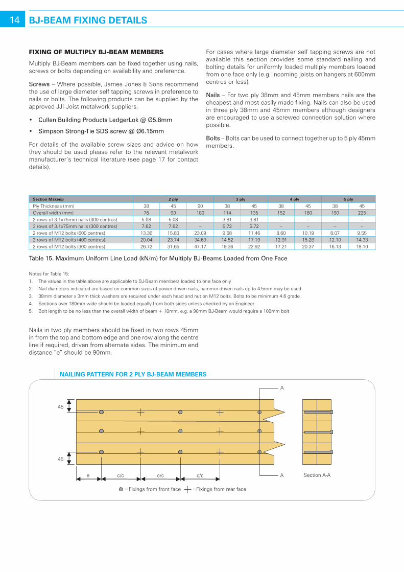
Ply Thickness (mm) 38 45 90 38 45 38 45 38 45Overall width (mm) 76 90 180 114 135 152 180 190 2252 rows of 3.1x75mm nails (300 centres) 5.08 5.08 – 3.81 3.81 – – – –3 rows of 3.1x75mm nails (300 centres) 7.62 7.62 – 5.72 5.72 – – – –2 rows of M12 bolts (600 centres) 13.36 15.83 23.09 9.68 11.46 8.60 10.19 8.07 9.552 rows of M12 bolts (400 centres) 20.04 23.74 34.63 14.52 17.19 12.91 15.28 12.10 14.332 rows of M12 bolts (300 centres) 26.72 31.65 47.17 19.36 22.92 17.21 20.37 16.13 19.10
table 15. Maximum uniform Line Load (kN/m) for Multiply BJ-Beams Loaded from one face
Notes for Table 15:
1. The values in the table above are applicable to BJ-Beam members loaded to one face only
2. Nail diameters indicated are based on common sizes of power driven nails, hammer driven nails up to 4.5mm may be used
3. 38mm diameter x 3mm thick washers are required under each head and nut on M12 bolts. Bolts to be minimum 4.6 grade
4. Sections over 180mm wide should be loaded equally from both sides unless checked by an Engineer
5. Bolt length to be no less than the overall width of beam + 18mm, e.g. a 90mm BJ-Beam would require a 108mm bolt
A
e
45
45
A Section A-A c/c c/c c/c
=Fixings from front face =Fixings from rear face
naIlInG PaTTern For 2 PlY bJ-beaM MeMbers
Nails in two ply members should be fixed in two rows 45mm in from the top and bottom edge and one row along the centre line if required, driven from alternate sides. The minimum end distance “e” should be 90mm.
15bJ-beaM FIxInG deTaIls
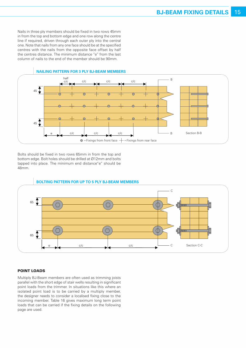
Nails in three ply members should be fixed in two rows 45mm in from the top and bottom edge and one row along the centre line if required, driven through each outer ply into the central one. Note that nails from any one face should be at the specified centres with the nails from the opposite face offset by half the centres distance. The minimum distance “e” from the last column of nails to the end of the member should be 90mm.
Bolts should be fixed in two rows 65mm in from the top and bottom edge. Bolt holes should be drilled at Ø12mm and bolts tapped into place. The minimum end distance“e” should be 48mm.
poInt loads
Multiply BJ-Beam members are often used as trimming joists parallel with the short edge of stair wells resulting in significant point loads from the trimmer. In situations like this where an isolated point load is to be carried by a multiply member, the designer needs to consider a localised fixing close to the incoming member. Table 16 gives maximum long term point loads that can be carried if the fixing details on the following page are used.
45
45
e c/c c/c c/c
c/c c/c half c/c c/c B
B Section B-B
=Fixings from front face =Fixings from rear face
naIlInG PaTTern For 3 PlY bJ-beaM MeMbers
65
65
c/c e c/c
C
C Section C-C
bolTInG PaTTern For uP To 5 PlY bJ-beaM MeMbers
16 bJ-beaM FIxInG deTaIls
section Makeup 2 ply 3 ply 4 ply
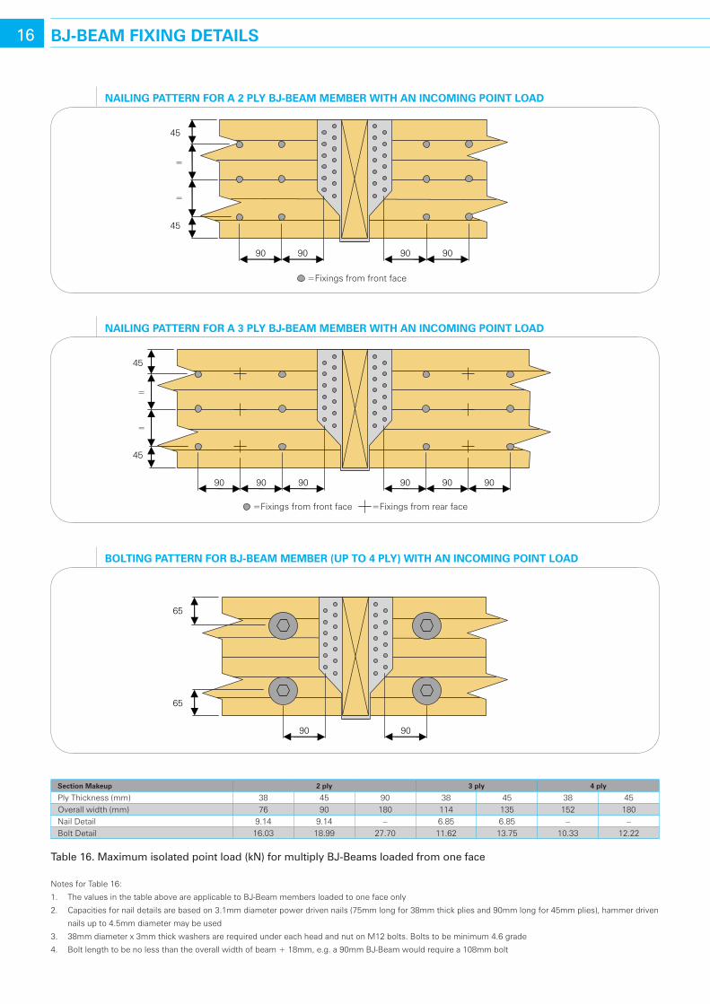
Ply Thickness (mm) 38 45 90 38 45 38 45Overall width (mm) 76 90 180 114 135 152 180Nail Detail 9.14 9.14 – 6.85 6.85 – –Bolt Detail 16.03 18.99 27.70 11.62 13.75 10.33 12.22
table 16. Maximum isolated point load (kN) for multiply BJ-Beams loaded from one face
Notes for Table 16:
1. The values in the table above are applicable to BJ-Beam members loaded to one face only
2. Capacities for nail details are based on 3.1mm diameter power driven nails (75mm long for 38mm thick plies and 90mm long for 45mm plies), hammer driven
nails up to 4.5mm diameter may be used
3. 38mm diameter x 3mm thick washers are required under each head and nut on M12 bolts. Bolts to be minimum 4.6 grade
4. Bolt length to be no less than the overall width of beam + 18mm, e.g. a 90mm BJ-Beam would require a 108mm bolt
45
45
=
=
9090 9090
=Fixings from front face
naIlInG PaTTern For a 2 PlY bJ-beaM MeMber wITh an IncoMInG PoInT load
45
45
=
=
9090 9090 9090
=Fixings from front face =Fixings from rear face
naIlInG PaTTern For a 3 PlY bJ-beaM MeMber wITh an IncoMInG PoInT load
65
65
9090
bolTInG PaTTern For bJ-beaM MeMber (uP To 4 PlY) wITh an IncoMInG PoInT load
17MeTalwork
JJI-JoIst connectIon hardware
James Jones & Sons continues to work closely with the UK’s leading timber engineering hardware manufacturers, developing ranges of fixings to suit JJI-Joists and BJ-Beam. The products include a complete range of fixings for timber to timber, timber to masonry and timber to steel connections. Only hardware approved by James Jones & Sons should be used with JJI-Joists and BJ-Beam to ensure quality construction standards. In addition, all approved hardware is automatically specified by James Jones & Sons JoistMaster and FloorMaster software.
All connection hardware/fixings are available from JJI-Joist Distributors as part of the JJI-Joist system.
Simpson Strong-Tie UKWinchester Road
Cardinal PointTamworth
StaffordshireB78 3HG
Tel: 01827 255600Fax: 01827 255616
www.strongtie.co.uk
Examples of suitable metalwork from Simpson Strong-tie:
the Safety fast hanger – a masonry hanger that can support load without the need for propping or masonry above to hold the hanger in place
the End Seal – a robust way to achieve an air tight seal when joists are built in to masonry walls
the ItB hanger – a timber hanger which significantly reduces the amount of Backer Blocks required
the hES restraint Strap – a 1.5mm thick restraint strap that is lighter, quicker and easier to fit than traditional 5mm thick straps
the ZS Clip – the easiest and quickest way to fit JJI-Joist noggings and timber noggings to supporting joists
General Notes
• FordetailsofnewlyapprovedmanufacturerscontactJamesJones&Sons
• Refertoapprovedmanufacturersliteraturefordetailsofhangerranges,safeworkingloads,nailingrequirementsandinstallationinstructions
• WebstiffenersarenotrequiredwhenapprovedhangersareusedunlesstheJJI-Joistdesignstatesotherwise
• DONOTUSENON-APPROVEDHANGERS–IFINDOUBT,ASK
Cullen Building Products1 Wheatstone Place
Southfield Industrial EstateGlenrothes
FifeKY6 2SW
Tel: 01592 771132Fax: 01592 771182www.cullen-bp.com
Examples of suitable metalwork from Cullen Building products:
the ffI hanger – the face fix timber to timber connector for an economical solution and a flat finished surface
the Gripper – the easy solution for Building Regulation compliance at JJI-Joist ends when building into masonry walls
the I-Clip – an alternative solution to traditional filler blocks for simple integrity inspection and a quicker on-site construction
the rA hanger – the easy to use safety solution for timber to masonry connections which is built off the same course of blockwork as built-in joists
the u hanger – a wrap over timber to timber connector that omits traditional backer block requirements
18 Floor desIGn
Factors aFFectIng Floor perFormance
The following list describes factors that affect floor performance and consideration of these factors may be helpful when designing and installing a JJI-Joist floor system:
Joist Depth
Deeper joists create a stiffer floor thereby reducing deflection. A deep floor joist solution may in fact be cheaper than a shallow joist solution as you may be able to use thinner joists at wider centres.
Deck fixing
A correctly nailed floor deck will improve floor performance by about 12%*. Gluing the floor deck to the joists, and gluing tongued and grooved joints is required by NHBC Standards Section 6.4 S1.9 and S2.0, and is also recommended in BS 7916. In addition, the floor performance can improve by as much as 70% when the floor deck is glued to the joists*.
Deck thickness
Thicker floor deck material will improve the floor performance.
Ceiling treatments
Directly applied ceiling finishes will improve floor performance by about 3%*.
Blocking
Full depth blocking will improve floor performance.
Workmanship
Good quality workmanship is essential to achieve good floor performance. The provision of well prepared and level bearings, methodical erection procedure, diligent installation of all fixings and in particular fixing of the floor deck (including gluing where required) will have a significant effect on floor performance. The maximum acceptable tolerance on the level of bearings is +/- 3mm.
* Figures obtained from independent laboratory tests originating from
a government (DETR) research project.
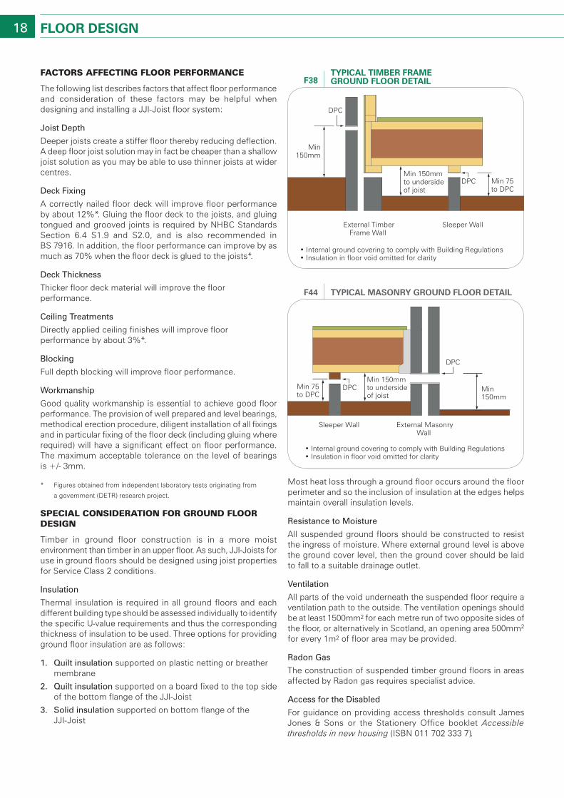
specIal consIderatIon For ground Floor desIgn
Timber in ground floor construction is in a more moist environment than timber in an upper floor. As such, JJI-Joists for use in ground floors should be designed using joist properties for Service Class 2 conditions.
Insulation
Thermal insulation is required in all ground floors and each different building type should be assessed individually to identify the specific U-value requirements and thus the corresponding thickness of insulation to be used. Three options for providing ground floor insulation are as follows:
1. Quilt insulation supported on plastic netting or breather membrane
2. Quilt insulation supported on a board fixed to the top side of the bottom flange of the JJI-Joist
3. Solid insulation supported on bottom flange of the JJI-Joist
Most heat loss through a ground floor occurs around the floor perimeter and so the inclusion of insulation at the edges helps maintain overall insulation levels.
resistance to Moisture
All suspended ground floors should be constructed to resist the ingress of moisture. Where external ground level is above the ground cover level, then the ground cover should be laid to fall to a suitable drainage outlet.
Ventilation
All parts of the void underneath the suspended floor require a ventilation path to the outside. The ventilation openings should be at least 1500mm2 for each metre run of two opposite sides of the floor, or alternatively in Scotland, an opening area 500mm2 for every 1m2 of floor area may be provided.
radon Gas
The construction of suspended timber ground floors in areas affected by Radon gas requires specialist advice.
Access for the Disabled
For guidance on providing access thresholds consult James Jones & Sons or the Stationery Office booklet Accessible thresholds in new housing (ISBN 011 702 333 7).
DPC
Min150mm
External TimberFrame Wall
Sleeper Wall
• Internal ground covering to comply with Building Regulations• Insulation in floor void omitted for clarity
Min 75to DPC
Min 150mmto undersideof joist
DPC
TYPIcal TIMber FraMe Ground Floor deTaIlF38
DPC
DPC
Min 150mm
External MasonryWall
Sleeper Wall
• Internal ground covering to comply with Building Regulations• Insulation in floor void omitted for clarity
Min 150mmto undersideof joist
Min 75to DPC
TYPIcal MasonrY Ground Floor deTaIlF44
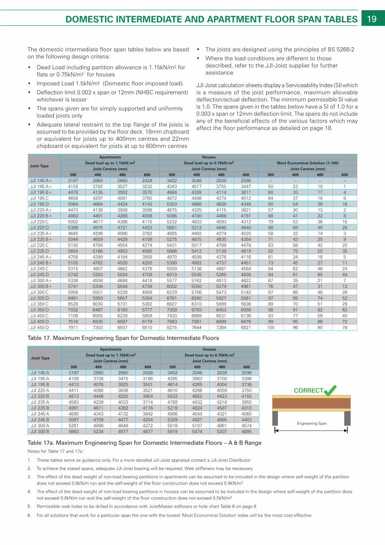
19doMesTIc InTerMedIaTe and aParTMenT Floor sPan Tables
Joist Type
apartments houses
dead load up to 1.15kn/m2 dead load up to 0.75kn/m2 Most economical solution (1-100)
Joist centres (mm) Joist centres (mm) Joist centres (mm)
300 400 480 600 300 400 480 600 300 400 480 600
JJI 145 A+ 3197 2860 2660 2428 3402 3048 2839 2596 – – – –JJI 195 A+ 4155 3782 3527 3232 4343 4017 3755 3447 50 23 10 1JJI 195 B+ 4478 4135 3902 3570 4684 4328 4114 3811 60 33 17 4JJI 195 C 4656 4297 4081 3760 4872 4498 4274 4012 64 37 19 6JJI 195 D 5064 4664 4424 4143 5303 4888 4639 4348 80 54 38 16JJI 220 A+ 4473 4136 3909 3586 4675 4325 4115 3821 57 30 13 2JJI 220 B+ 4863 4491 4268 4006 5086 4700 4468 4197 68 41 22 8JJI 220 C 5002 4617 4386 4115 5232 4833 4593 4312 79 53 36 15JJI 220 D 5398 4975 4721 4423 5651 5212 4948 4640 88 69 49 28JJI 235 A+ 4645 4296 4086 3782 4855 4492 4274 4020 58 32 14 3JJI 235 B+ 5044 4659 4428 4158 5275 4875 4635 4354 71 43 25 9JJI 235 C 5192 4794 4554 4274 5431 5017 4769 4478 83 56 42 20JJI 235 D 5604 5166 4903 4595 5866 5412 5139 4819 92 75 55 35JJI 245 A+ 4756 4399 4184 3908 4970 4599 4376 4116 61 34 18 5JJI 245 B+ 5155 4762 4526 4250 5390 4982 4737 4451 73 45 27 11JJI 245 C 5315 4907 4662 4376 5559 5136 4881 4584 84 62 46 24JJI 245 D 5742 5293 5024 4709 6010 5545 5265 4938 94 81 65 44JJI 300 A+ 5338 4938 4698 4418 5577 5162 4913 4622 67 39 21 7JJI 300 B+ 5741 5306 5044 4739 6002 5550 5279 4961 76 47 31 12JJI 300 C 5956 5501 5228 4909 6229 5756 5473 5142 87 66 48 26JJI 300 D 6461 5959 5657 5304 6761 6240 5927 5561 97 85 74 52JJI 350 C 6528 6030 5731 5382 6827 6310 5999 5636 89 70 51 29JJI 350 D 7032 6487 6160 5777 7359 6793 6453 6056 98 91 82 63JJI 400 C 7108 6565 6239 5859 7433 6869 6531 6136 93 77 59 40JJI 400 D 7516 6935 6587 6179 7863 7261 6899 6476 99 95 86 72JJI 450 D 7911 7303 6937 6510 8275 7644 7264 6821 100 96 90 78
table 17. Maximum Engineering Span for Domestic Intermediate floors
Joist Type
apartments houses
dead load up to 1.15kn/m2 dead load up to 0.75kn/m2
Joist centres (mm) Joist centres (mm)
300 400 480 600 300 400 480 600
JJI 145 A 3197 2860 2660 2428 3402 3048 2839 2596JJI 195 A 4109 3726 3475 3186 4295 3963 3700 3396JJI 195 B 4413 4076 3825 3501 4614 4265 4054 3736JJI 220 A 4411 4080 3836 3521 4610 4266 4059 3750JJI 220 B 4813 4446 4225 3954 5033 4652 4423 4155JJI 235 A 4583 4239 4033 3714 4789 4432 4218 3955JJI 235 B 4991 4611 4382 4116 5219 4824 4587 4310JJI 245 A 4695 4343 4132 3842 4906 4540 4321 4065JJI 245 B 5097 4709 4477 4204 5329 4927 4685 4403JJI 300 A 5281 4886 4649 4372 5518 5107 4861 4574JJI 300 B 5663 5234 4977 4677 5919 5474 5207 4895
table 17a. Maximum Engineering Span for Domestic Intermediate floors – A & B rangeNotes for Table 17 and 17a:
The domestic intermediate floor span tables below are based on the following design criteria:
• DeadLoadincludingpartitionallowanceis1.15kN/m2 for flats or 0.75kN/m2 for houses
• ImposedLoad1.5kN/m2 (Domestic floor imposed load).
• Deflectionlimit0.003xspanor12mm(NHBCrequirement)whichever is lesser
• Thespansgivenareforsimplysupportedanduniformlyloaded joists only
• Adequatelateralrestrainttothetopflangeofthejoistsisassumed to be provided by the floor deck. 18mm chipboard or equivalent for joists up to 400mm centres and 22mm chipboard or equivalent for joists at up to 600mm centres
• ThejoistsaredesignedusingtheprinciplesofBS5268-2
• Wheretheloadconditionsaredifferenttothosedescribed, refer to the JJI-Joist supplier for further assistance
JJI-Joist calculation sheets display a Serviceability Index (SI) which is a measure of the joist performance, maximum allowable deflection/actual deflection. The minimum permissible SI value is 1.0. The spans given in the tables below have a SI of 1.0 for a 0.003 x span or 12mm deflection limit. The spans do not include any of the beneficial effects of the various factors which may affect the floor performance as detailed on page 18.
1. These tables serve as guidance only. For a more detailed JJI-Joist appraisal contact a JJI-Joist Distributor
2. To achieve the stated spans, adequate JJI-Joist bearing will be required. Web stiffeners may be necessary
3. The effect of the dead weight of non-load bearing partitions in apartments can be assumed to be included in the design where self-weight of the partition does not exceed 0.8kN/m run and the self-weight of the floor construction does not exceed 0.9kN/m2
4. The effect of the dead weight of non-load bearing partitions in houses can be assumed to be included in the design where self-weight of the partition does not exceed 0.8kN/m run and the self-weight of the floor construction does not exceed 0.5kN/m2
5. Permissible web holes to be drilled in accordance with JoistMaster software or hole chart Table 6 on page 8
6. For all solutions that work for a particular span the one with the lowest 'Most Economical Solution' index will be the most cost effective
Engineering Span
CORRECT
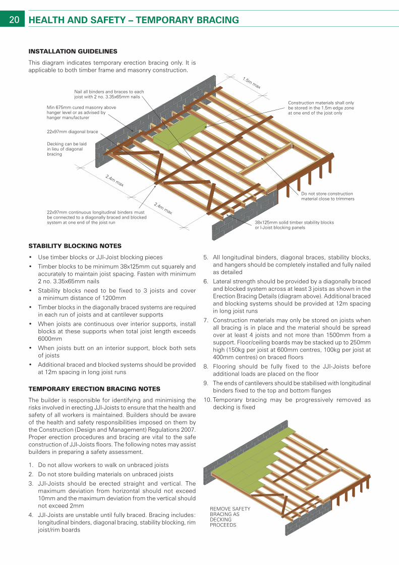
22x97mm diagonal brace
22x97mm continuous longitudinal binders mustbe connected to a diagonally braced and blockedsystem at one end of the joist run 38x125mm solid timber stability blocks
or I-Joist blocking panels
Decking can be laid in lieu of diagonal bracing
Do not store constructionmaterial close to trimmers
Construction materials shall only be stored in the 1.5m edge zone at one end of the joist only
Nail all binders and braces to eachjoist with 2 no. 3.35x65mm nails
Min 675mm cured masonry abovehanger level or as advised byhanger manufacturer
1.5m max
2.4m max
2.4m max
20 healTh and saFeTY – TeMPorarY bracInG
InstallatIon guIdelInes
This diagram indicates temporary erection bracing only. It is applicable to both timber frame and masonry construction.
staBIlIty BlockIng notes
• UsetimberblocksorJJI-Joistblockingpieces
• Timberblockstobeminimum38x125mmcutsquarelyandaccurately to maintain joist spacing. Fasten with minimum 2 no. 3.35x65mm nails
• Stability blocks need to be fixed to 3 joists and cover a minimum distance of 1200mm
• Timberblocksinthediagonallybracedsystemsarerequiredin each run of joists and at cantilever supports
• Whenjoistsarecontinuousover interiorsupports, installblocks at these supports when total joist length exceeds 6000mm
• Whenjoistsbuttonan interiorsupport,blockbothsets of joists
• Additionalbracedandblockedsystemsshouldbeprovidedat 12m spacing in long joist runs
temporary erectIon BracIng notes
The builder is responsible for identifying and minimising the risks involved in erecting JJI-Joists to ensure that the health and safety of all workers is maintained. Builders should be aware of the health and safety responsibilities imposed on them by the Construction (Design and Management) Regulations 2007. Proper erection procedures and bracing are vital to the safe construction of JJI-Joists floors. The following notes may assist builders in preparing a safety assessment.
1. Do not allow workers to walk on unbraced joists
2. Do not store building materials on unbraced joists
3. JJI-Joists should be erected straight and vertical. The maximum deviation from horizontal should not exceed 10mm and the maximum deviation from the vertical should not exceed 2mm
4. JJI-Joists are unstable until fully braced. Bracing includes: longitudinal binders, diagonal bracing, stability blocking, rim joist/rim boards
5. All longitudinal binders, diagonal braces, stability blocks, and hangers should be completely installed and fully nailed as detailed
6. Lateral strength should be provided by a diagonally braced and blocked system across at least 3 joists as shown in the Erection Bracing Details (diagram above). Additional braced and blocking systems should be provided at 12m spacing in long joist runs
7. Construction materials may only be stored on joists when all bracing is in place and the material should be spread over at least 4 joists and not more than 1500mm from a support. Floor/ceiling boards may be stacked up to 250mm high (150kg per joist at 600mm centres, 100kg per joist at 400mm centres) on braced floors
8. Flooring should be fully fixed to the JJI-Joists before additional loads are placed on the floor
9. The ends of cantilevers should be stabilised with longitudinal binders fixed to the top and bottom flanges
10. Temporary bracing may be progressively removed as decking is fixed
REMOVE SAFETY BRACING AS DECKING PROCEEDS
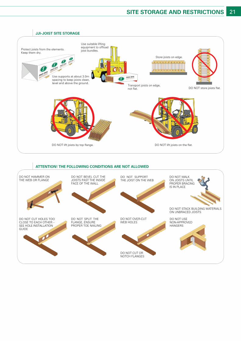
21sITe sToraGe and resTrIcTIons
Protect joists from the elements.Keep them dry.
Use supports at about 3.0mspacing to keep joists clean,level and above the ground.
Use suitable liftingequipment to offloadjoist bundles.
Transport joists on edge,not flat.
Store joists on edge.
DO NOT store joists flat.
DO NOT lift joists by top flange. DO NOT lift joists on the flat.
TIMBER SYSTEMS DIVISION
JJI-JoIsT sITe sToraGe
DO NOT HAMMER ONTHE WEB OR FLANGE
DO NOT BEVEL CUT THEJOISTS PAST THE INSIDEFACE OF THE WALL
DO NOT SUPPORTTHE JOIST ON THE WEB
DO NOT WALK ON JOISTS UNTILPROPER BRACINGIS IN PLACE
DO NOT STACK BUILDING MATERIALSON UNBRACED JOISTS
DO NOT USENON-APPROVEDHANGERS
DO NOT OVER-CUTWEB HOLES
DO NOT SPLIT THE FLANGE, ENSUREPROPER TOE NAILING
DO NOT CUT HOLES TOO CLOSE TO EACH OTHER – SEE HOLE INSTALLATION GUIDE
DO NOT CUT ORNOTCH FLANGES
aTTenTIon! The FollowInG condITIons are noT allowed
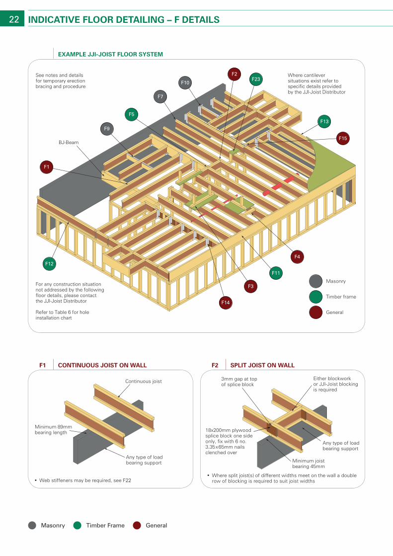
22 IndIcaTIVe Floor deTaIlInG – F deTaIls
• Web stiffeners may be required, see F22
Minimum 89mm bearing length
Any type of load bearing support
Continuous joist
conTInuous JoIsT on wallF1
See notes and details for temporary erection bracing and procedure
For any construction situation not addressed by the following floor details, please contact the JJI-Joist Distributor
Where cantilever situations exist refer to specific details provided by the JJI-Joist Distributor
Refer to Table 6 for hole installation chart
BJ-Beam
F5
F14
F9
F7
F1
F10
F2F23
F13
F15
F4
F11
F3
F12
Masonry
Timber frame
General
exaMPle JJI-JoIsT Floor sYsTeM
• Where split joist(s) of different widths meet on the wall a double row of blocking is required to suit joist widths
Either blockwork or JJI-Joist blocking is required
18x200mm plywood splice block one side only, fix with 6 no. 3.35x65mm nails clenched over
3mm gap at top of splice block
Minimum joist bearing 45mm
Any type of load bearing support
sPlIT JoIsT on wallF2
Masonry timber frame General
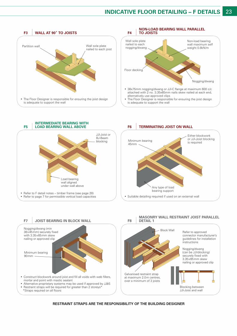
23IndIcaTIVe Floor deTaIlInG – F deTaIls
• The Floor Designer is responsible for ensuring the joist design is adequate to support the wall
Partition wall Wall sole plate nailed to each joist
wall aT 90˚ To JoIsTsF3
• Suitable detailing required if used on an external wall
Either blockwork or JJI-Joist blocking is requiredMinimum bearing
45mm
Any type of load bearing support
TerMInaTInG JoIsT on wallF6
• 38x75mm nogging/dwang or JJI-C flange at maximum 600 c/c attached with 2 no. 3.35x65mm nails skew nailed at each end, alternatively use approved clips
• The Floor Designer is responsible for ensuring the joist design is adequate to support the wall
Non-load bearing wall maximum self weight 0.8kN/m
Floor decking
Wall sole plate nailed to each nogging/dwang
Nogging/dwang
non-load bearInG wall Parallel To JoIsTsF4
• Refer to F detail notes – timber frame (see page 28)• Refer to page 7 for permissible vertical load capacities
Load bearing wall aligned under wall above
JJI-Joist or BJ-Beam blocking
InTerMedIaTe bearInG wITh load bearInG wall aboVeF5
• Construct blockwork around joist and fill all voids with web fillers, mortar and point with mastic sealant
• Alternative proprietary systems may be used if approved by JJ&S• Restraint straps will be required for greater than 2 storeys* *Straps required on all floors
Nogging/dwang (min 38x45mm) securely fixed with 3.35x65mm skew nailing or approved clip
Minimum bearing 90mm
JoIsT bearInG In block wallF7
Block Wall
Galvanised restraint strap at maximum 2.0m centres, over a minimum of 3 joists
Blocking between JJI-Joist and wall
Refer to approved connector manufacturer’s guidelines for installation instructions
Nogging/dwang (can be JJI-blocking) securely fixed with 3.35x65mm skew nailing or approved clip
MasonrY wall resTraInT JoIsT Parallel deTaIl 1F8
resTraInT sTraPs are The resPonsIbIlITY oF The buIldInG desIGner
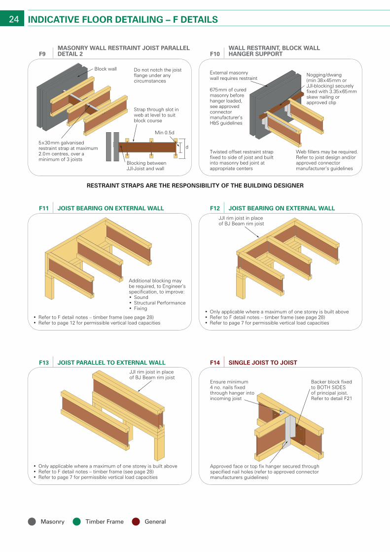
24 IndIcaTIVe Floor deTaIlInG – F deTaIls
Approved face or top fix hanger secured through specified nail holes (refer to approved connector manufacturers guidelines)
Backer block fixed to BOTH SIDES of principal joist. Refer to detail F21
Ensure minimum 4 no. nails fixed through hanger into incoming joist
sInGle JoIsT To JoIsTF14
• Only applicable where a maximum of one storey is built above• Refer to F detail notes – timber frame (see page 28)• Refer to page 7 for permissible vertical load capacities
JJI rim joist in place of BJ Beam rim joist
JoIsT bearInG on exTernal wallF12
• Refer to F detail notes – timber frame (see page 28)• Refer to page 12 for permissible vertical load capacities
Additional blocking may be required, to Engineer’s specification, to improve:• Sound• Structural Performance• Fixing
JoIsT bearInG on exTernal wallF11
• Only applicable where a maximum of one storey is built above• Refer to F detail notes – timber frame (see page 28)• Refer to page 7 for permissible vertical load capacities
JJI rim joist in place of BJ Beam rim joist
JoIsT Parallel To exTernal wallF13
Strap through slot in web at level to suit block course
Min 0.5d
Blocking between JJI-Joist and wall
Block wall
5x30mm galvanised restraint strap at maximum 2.0m centres, over a minimum of 3 joists
Do not notch the joist flange under any circumstances
d
MasonrY wall resTraInT JoIsT Parallel deTaIl 2F9
External masonry wall requires restraint
Twisted offset restraint strap fixed to side of joist and built into masonry bed joint at appropriate centers
Nogging/dwang (min 38x45mm or JJI-blocking) securely fixed with 3.35x65mm skew nailing or approved clip
675mm of cured masonry before hanger loaded, see approved connector manufacturer’s H&S guidelines
Web fillers may be required. Refer to joist design and/or approved connector manufacturer’s guidelines
wall resTraInT, block wall hanGer suPPorTF10
Masonry timber frame General
resTraInT sTraPs are The resPonsIbIlITY oF The buIldInG desIGner
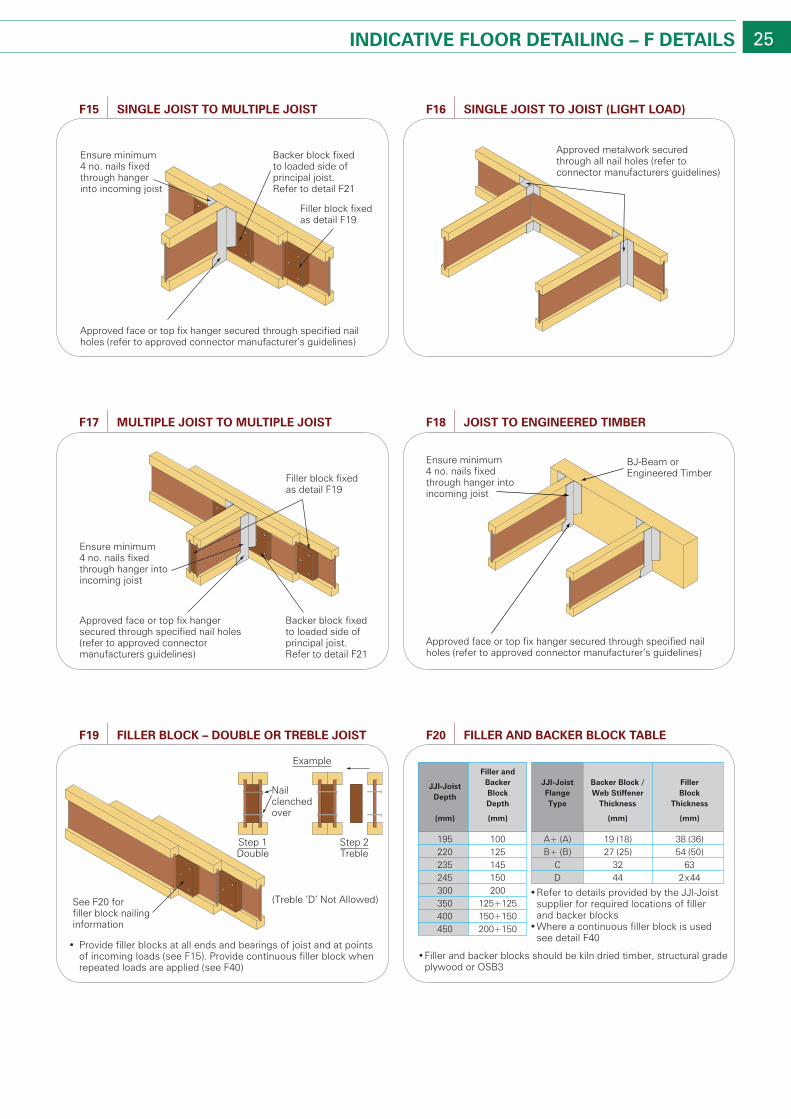
25IndIcaTIVe Floor deTaIlInG – F deTaIls
Approved face or top fix hanger secured through specified nail holes (refer to approved connector manufacturers guidelines)
Backer block fixed to loaded side of principal joist. Refer to detail F21
Filler block fixed as detail F19
Ensure minimum 4 no. nails fixed through hanger into incoming joist
MulTIPle JoIsT To MulTIPle JoIsTF17
Approved face or top fix hanger secured through specified nail holes (refer to approved connector manufacturer’s guidelines)
BJ-Beam or Engineered Timber
Ensure minimum 4 no. nails fixed through hanger into incoming joist
JoIsT To enGIneered TIMberF18
• Provide filler blocks at all ends and bearings of joist and at points of incoming loads (see F15). Provide continuous filler block when repeated loads are applied (see F40)
(Treble ‘D’ Not Allowed)See F20 for filler block nailing information
Step 1Double
Example
Nail clenched over
Step 2Treble
FIller block – double or Treble JoIsTF19
• Refer to details provided by the JJI-Joist supplier for required locations of filler and backer blocks
• Where a continuous filler block is used see detail F40
195 100 A+ (A) 19 (18)220 125 B+ (B) 27 (25)235 145 C 32245 150 D 44
38 (36)54 (50)
632x44
300 200350 125+125400 150+150450 200+150
JJI-JoistDepth
(mm)
Filler andBackerBlockDepth
(mm)
JJI-JoistFlangeType
Backer Block /Web Stiffener
Thickness
(mm)
FillerBlock
Thickness
(mm)
• Filler and backer blocks should be kiln dried timber, structural grade plywood or OSB3
FIller and backer block TableF20
Approved face or top fix hanger secured through specified nail holes (refer to approved connector manufacturer’s guidelines)
Backer block fixed to loaded side of principal joist. Refer to detail F21
Filler block fixed as detail F19
Ensure minimum 4 no. nails fixed through hanger into incoming joist
sInGle JoIsT To MulTIPle JoIsTF15
Approved metalwork secured through all nail holes (refer to connector manufacturers guidelines)
sInGle JoIsT To JoIsT (lIGhT load)F16
26 IndIcaTIVe Floor deTaIlInG – F deTaIls
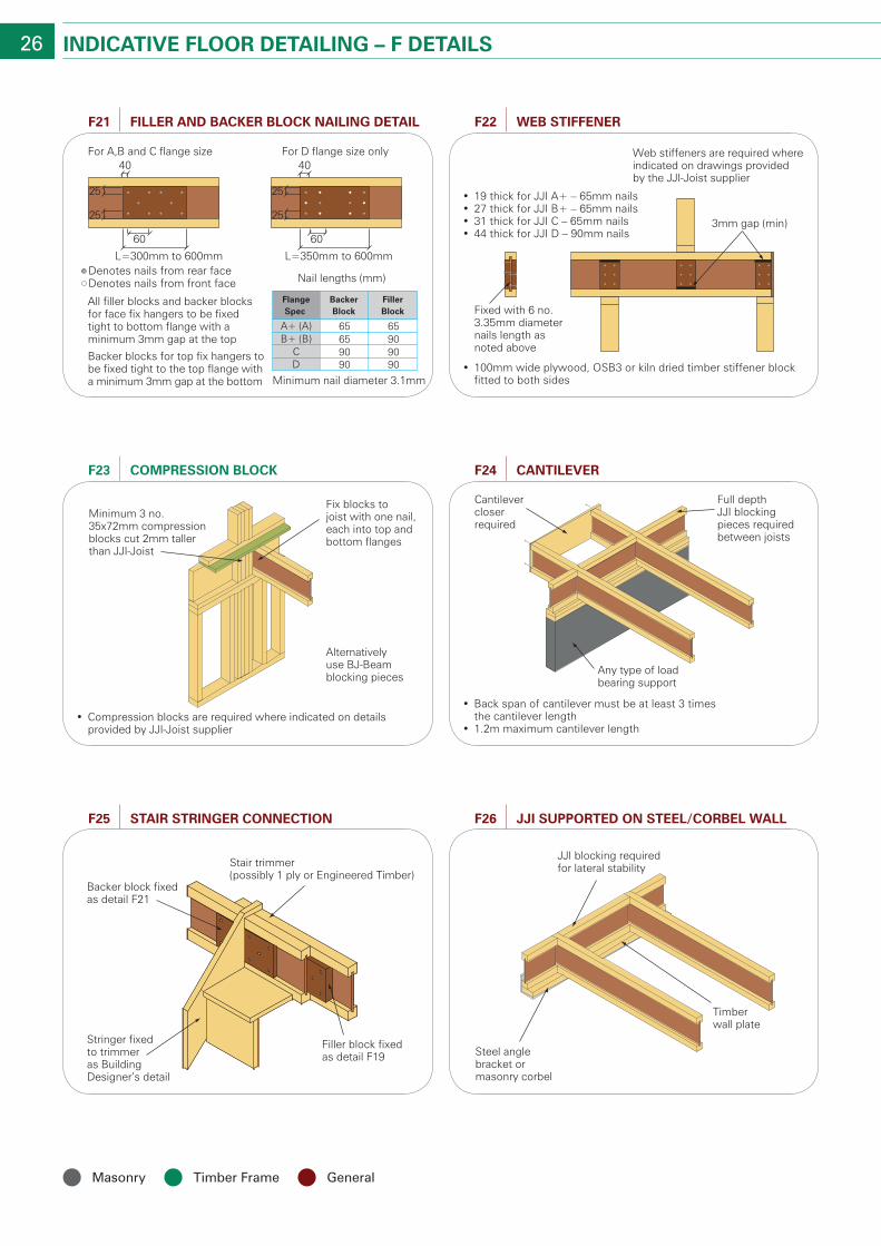
• Compression blocks are required where indicated on details provided by JJI-Joist supplier
Minimum 3 no. 35x72mm compression blocks cut 2mm taller than JJI-Joist
Fix blocks to joist with one nail, each into top and bottom flanges
Alternatively use BJ-Beam blocking pieces
coMPressIon blockF23
All filler blocks and backer blocks for face fix hangers to be fixed tight to bottom flange with a minimum 3mm gap at the top
Backer blocks for top fix hangers to be fixed tight to the top flange with a minimum 3mm gap at the bottom
L=300mm to 600mm
25
40
60
For A,B and C flange size For D flange size only
25
2525
40
L=350mm to 600mm
60
A+ (A) 65B+ (B) 65
C 90D 90
65909090
FlangeSpec
BackerBlock
FillerBlock
Nail lengths (mm)
Minimum nail diameter 3.1mm
FIller and backer block naIlInG deTaIlF21
• 19 thick for JJI A+ – 65mm nails• 27 thick for JJI B+ – 65mm nails• 31 thick for JJI C – 65mm nails• 44 thick for JJI D – 90mm nails
3mm gap (min)
• 100mm wide plywood, OSB3 or kiln dried timber stiffener block fitted to both sides
Fixed with 6 no. 3.35mm diameter nails length as noted above
Web stiffeners are required where indicated on drawings provided by the JJI-Joist supplier
web sTIFFenerF22
• Back span of cantilever must be at least 3 times the cantilever length
• 1.2m maximum cantilever length
Full depth JJI blocking pieces required between joists
Cantilever closer required
Any type of load bearing support
canTIleVerF24
JJI blocking required for lateral stability
Steel angle bracket or masonry corbel
Timber wall plate
JJI suPPorTed on sTeel/corbel wallF26
Backer block fixed as detail F21
Stringer fixed to trimmer as Building Designer’s detail
Stair trimmer (possibly 1 ply or Engineered Timber)
Filler block fixed as detail F19
sTaIr sTrInGer connecTIonF25
Masonry timber frame General
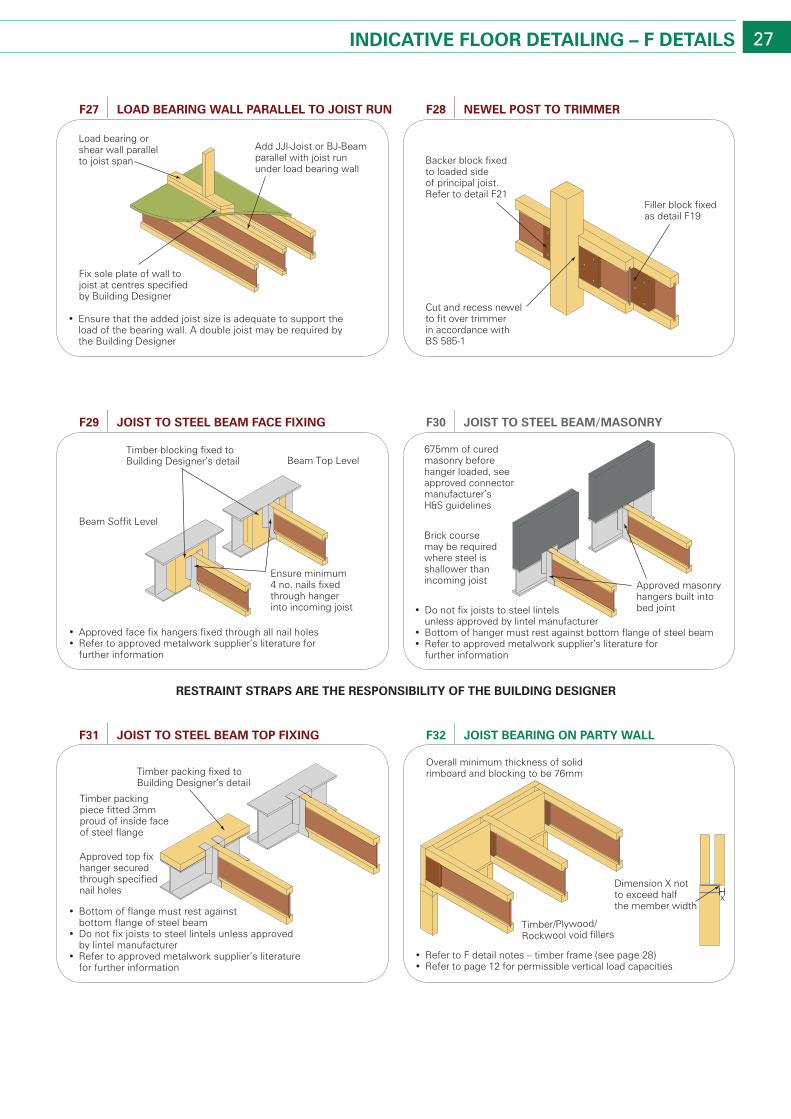
27IndIcaTIVe Floor deTaIlInG – F deTaIls
• Refer to F detail notes – timber frame (see page 28)• Refer to page 12 for permissible vertical load capacities
Overall minimum thickness of solid rimboard and blocking to be 76mm
Timber/Plywood/Rockwool void fillers
xDimension X not to exceed half the member width
JoIsT bearInG on ParTY wallF32
• Ensure that the added joist size is adequate to support the load of the bearing wall. A double joist may be required by the Building Designer
Add JJI-Joist or BJ-Beam parallel with joist run under load bearing wall
Load bearing or shear wall parallel to joist span
Fix sole plate of wall to joist at centres specified by Building Designer
load bearInG wall Parallel To JoIsT runF27
Cut and recess newel to fit over trimmer in accordance with BS 585-1
Filler block fixedas detail F19
Backer block fixed to loaded side of principal joist. Refer to detail F21
newel PosT To TrIMMerF28
• Approved face fix hangers fixed through all nail holes• Refer to approved metalwork supplier’s literature for
further information
Beam Soffit Level
Beam Top LevelTimber blocking fixed to Building Designer’s detail
Ensure minimum 4 no. nails fixed through hanger into incoming joist
JoIsT To sTeel beaM Face FIxInGF29
675mm of cured masonry before hanger loaded, see approved connector manufacturer’s H&S guidelines
• Do not fix joists to steel lintels unless approved by lintel manufacturer
• Bottom of hanger must rest against bottom flange of steel beam• Refer to approved metalwork supplier’s literature for
further information
Approved masonry hangers built into bed joint
Brick course may be required where steel is shallower than incoming joist
JoIsT To sTeel beaM/MasonrYF30
• Bottom of flange must rest against bottom flange of steel beam
• Do not fix joists to steel lintels unless approved by lintel manufacturer
• Refer to approved metalwork supplier’s literature for further information
Timber packing fixed toBuilding Designer’s detail
Timber packing piece fitted 3mm proud of inside face of steel flange
Approved top fix hanger secured through specified nail holes
JoIsT To sTeel beaM ToP FIxInGF31
resTraInT sTraPs are The resPonsIbIlITY oF The buIldInG desIGner
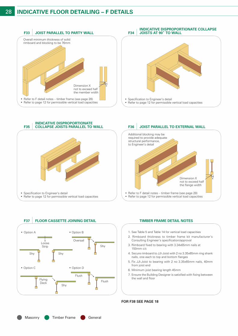
28 IndIcaTIVe Floor deTaIlInG – F deTaIls
• Refer to F detail notes – timber frame (see page 28)• Refer to page 12 for permissible vertical load capacities
Overall minimum thickness of solid rimboard and blocking to be 76mm
Dimension X not to exceed half the member width
x
JoIsT Parallel To ParTY wallF33
• Specification to Engineer’s detail• Refer to page 12 for permissible vertical load capacities
IndIcaTIVe dIsProPorTIonaTe collaPse JoIsTs aT 90˚ To wallF34
• Specification to Engineer’s detail• Refer to page 12 for permissible vertical load capacities
IndIcaTIVe dIsProPorTIonaTe collaPse JoIsTs Parallel To wallF35
• Refer to F detail notes – timber frame (see page 28)• Refer to page 12 for permissible vertical load capacities
Additional blocking may be required to provide adequate structural performance, to Engineer’s detail
Dimension X not to exceed half the flange width
x
JoIsT Parallel To exTernal wallF36
Shy
Oversail
• Option B• Option A
• Option D• Option C
Shy
LooseStrip
Shy
ShyFlush
FlushFlyingDeck
Floor casseTTe JoInInG deTaIlF37
For F38 see PaGe 18
TIMber FraMe deTaIl noTes
1. See Table 5 and Table 14 for vertical load capacities
2. Rimboard thickness to timber frame kit manufacturer’s Consulting Engineer’s specification/approval
3. Rimboard fixed to bearing with 3.34x65mm nails at 150mm c/c
4. Secure rimboard to JJI-Joist with 2 no 3.35x65mm ring shank nails, one each to top and bottom flanges
5. Fix JJI-Joist to bearing with 2 no 3.35x65mm nails, 40mm from joist end
6. Minimum joist bearing length 45mm
7. Ensure the Building Designer is satisfied with fixing between the wall and floor
Masonry timber frame General
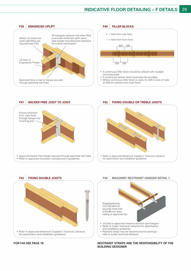
29IndIcaTIVe Floor deTaIlInG – F deTaIls
resTraInT sTraPs are The resPonsIbIlITY oF The buIldInG desIGner
For F44 see PaGe 18
• JJI-Joist in approved masonry restraint type hangers• Refer to Cullen Technical Literature for specification
and installation guidelines• Restraint straps may be required around openings –
refer to Cullen technical literature
Nogging/dwang (min 38x45mm) securely fixed with 3.35x65mm skew nailing or approved clip
MasonrY resTraInT hanGer deTaIl 1F45
• A continuous filler block should be utilised with multiple incoming loads
• A continuous backer block could also be provided• Where continuous filler block is used, fix with 2 rows of nails
at 300mm centres from both faces
300 300
300 300
FIller blocksF40
Approved face or top fix hanger secured through specified nail holes
Where JJI-Joists are used web fillers are required (see F22)
All triangular optional nail holes filled to provide enhanced uplift value (see hanger manufacturers literature for further information)
JJI-Joist or Engineered Timber
enhanced uPlIFTF39
• Approved backer free hanger secured through specified nail holes• Refer to approved connector manufacturer’s guidelines
Ensure minimum 4 no. nails fixed through hanger into incoming joist
backer Free JoIsT To JoIsTF41
• Refer to Approved Metalwork Supplier’s Technical Literature for specification and installation guidelines
FIxInG double or Treble JoIsTsF42
• Refer to Approved Metalwork Supplier’s Technical Literature for specification and installation guidelines
FIxInG double JoIsTsF43
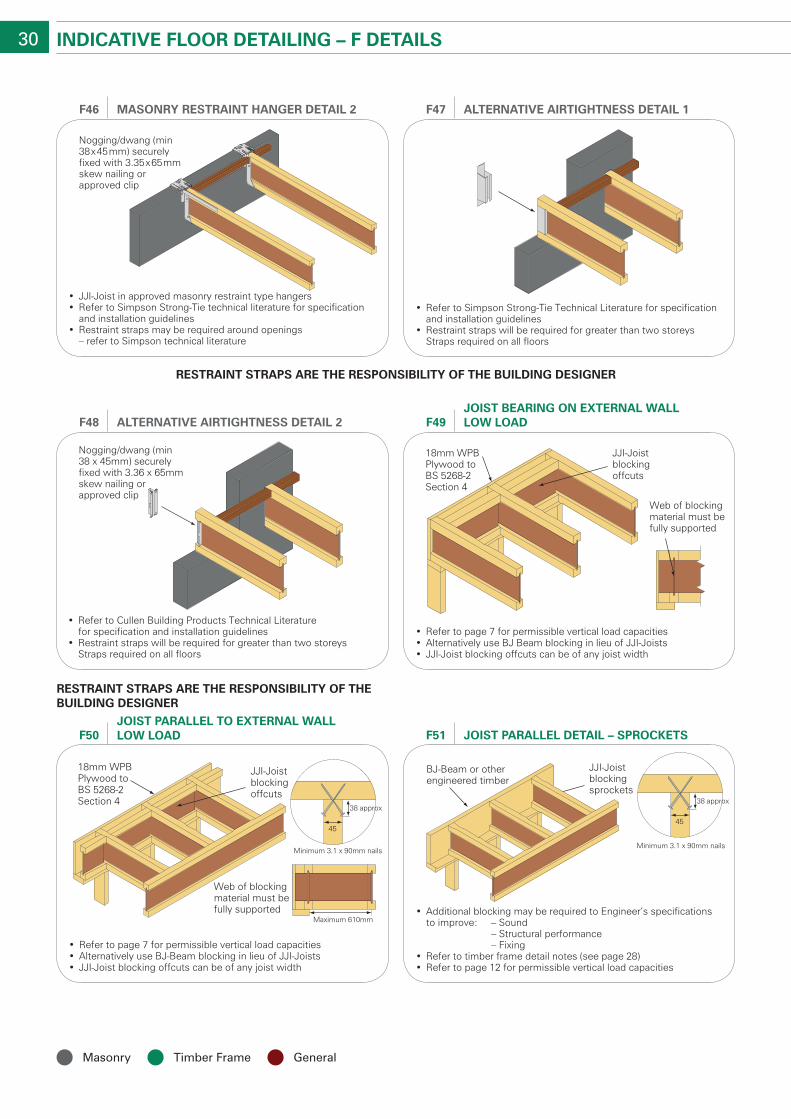
30 IndIcaTIVe Floor deTaIlInG – F deTaIls
• Refer to Simpson Strong-Tie Technical Literature for specification and installation guidelines
• Restraint straps will be required for greater than two storeys Straps required on all floors
alTernaTIVe aIrTIGhTness deTaIl 1F47
• JJI-Joist in approved masonry restraint type hangers• Refer to Simpson Strong-Tie technical literature for specification
and installation guidelines• Restraint straps may be required around openings
– refer to Simpson technical literature
Nogging/dwang (min 38x45mm) securely fixed with 3.35x65mm skew nailing or approved clip
MasonrY resTraInT hanGer deTaIl 2F46
• Refer to Cullen Building Products Technical Literature for specification and installation guidelines
• Restraint straps will be required for greater than two storeys Straps required on all floors
Nogging/dwang (min38 x 45mm) securelyfixed with 3.36 x 65mmskew nailing orapproved clip
alTernaTIVe aIrTIGhTness deTaIl 2F48
• Refer to page 7 for permissible vertical load capacities• Alternatively use BJ Beam blocking in lieu of JJI-Joists• JJI-Joist blocking offcuts can be of any joist width
18mm WPB Plywood to BS 5268-2Section 4
JJI-Joist blockingoffcuts
Web of blockingmaterial must befully supported
JoIsT bearInG on exTernal wall low loadF49
Web of blockingmaterial must befully supported
Maximum 610mm
Minimum 3.1 x 90mm nails
45
38 approx
18mm WPB Plywood to BS 5268-2Section 4
JJI-Joist blockingoffcuts
• Refer to page 7 for permissible vertical load capacities• Alternatively use BJ-Beam blocking in lieu of JJI-Joists• JJI-Joist blocking offcuts can be of any joist width
JoIsT Parallel To exTernal wall low loadF50
Minimum 3.1 x 90mm nails
BJ-Beam or other engineered timber
JJI-Joist blockingsprockets
• Additional blocking may be required to Engineer’s specificationsto improve: – Sound
– Structural performance – Fixing
• Refer to timber frame detail notes (see page 28)• Refer to page 12 for permissible vertical load capacities
45
38 approx
JoIsT Parallel deTaIl – sProckeTsF51
resTraInT sTraPs are The resPonsIbIlITY oF The buIldInG desIGner
resTraInT sTraPs are The resPonsIbIlITY oF The buIldInG desIGner
Masonry timber frame General
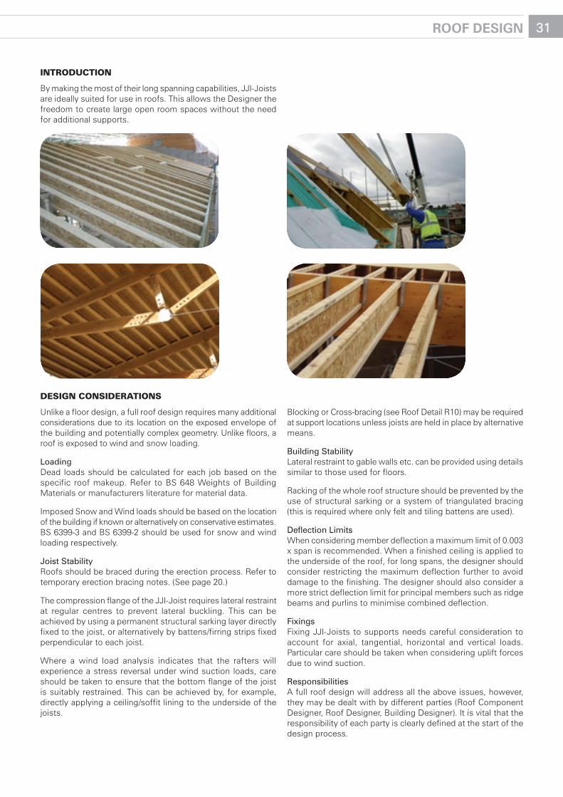
31rooF desIGn
IntroductIon
By making the most of their long spanning capabilities, JJI-Joists are ideally suited for use in roofs. This allows the Designer the freedom to create large open room spaces without the need for additional supports.
desIgn consIderatIons
Unlike a floor design, a full roof design requires many additional considerations due to its location on the exposed envelope of the building and potentially complex geometry. Unlike floors, a roof is exposed to wind and snow loading.
LoadingDead loads should be calculated for each job based on the specific roof makeup. Refer to BS 648 Weights of Building Materials or manufacturers literature for material data.
Imposed Snow and Wind loads should be based on the location of the building if known or alternatively on conservative estimates. BS 6399-3 and BS 6399-2 should be used for snow and wind loading respectively.
Joist StabilityRoofs should be braced during the erection process. Refer to temporary erection bracing notes. (See page 20.)
The compression flange of the JJI-Joist requires lateral restraint at regular centres to prevent lateral buckling. This can be achieved by using a permanent structural sarking layer directly fixed to the joist, or alternatively by battens/firring strips fixed perpendicular to each joist.
Where a wind load analysis indicates that the rafters will experience a stress reversal under wind suction loads, care should be taken to ensure that the bottom flange of the joist is suitably restrained. This can be achieved by, for example, directly applying a ceiling/soffit lining to the underside of the joists.
Blocking or Cross-bracing (see Roof Detail R10) may be required at support locations unless joists are held in place by alternative means.
Building StabilityLateral restraint to gable walls etc. can be provided using details similar to those used for floors.
Racking of the whole roof structure should be prevented by the use of structural sarking or a system of triangulated bracing (this is required where only felt and tiling battens are used).
Deflection LimitsWhen considering member deflection a maximum limit of 0.003 x span is recommended. When a finished ceiling is applied to the underside of the roof, for long spans, the designer should consider restricting the maximum deflection further to avoid damage to the finishing. The designer should also consider a more strict deflection limit for principal members such as ridge beams and purlins to minimise combined deflection.
fixingsFixing JJI-Joists to supports needs careful consideration to account for axial, tangential, horizontal and vertical loads. Particular care should be taken when considering uplift forces due to wind suction.
responsibilitiesA full roof design will address all the above issues, however, they may be dealt with by different parties (Roof Component Designer, Roof Designer, Building Designer). It is vital that the responsibility of each party is clearly defined at the start of the design process.
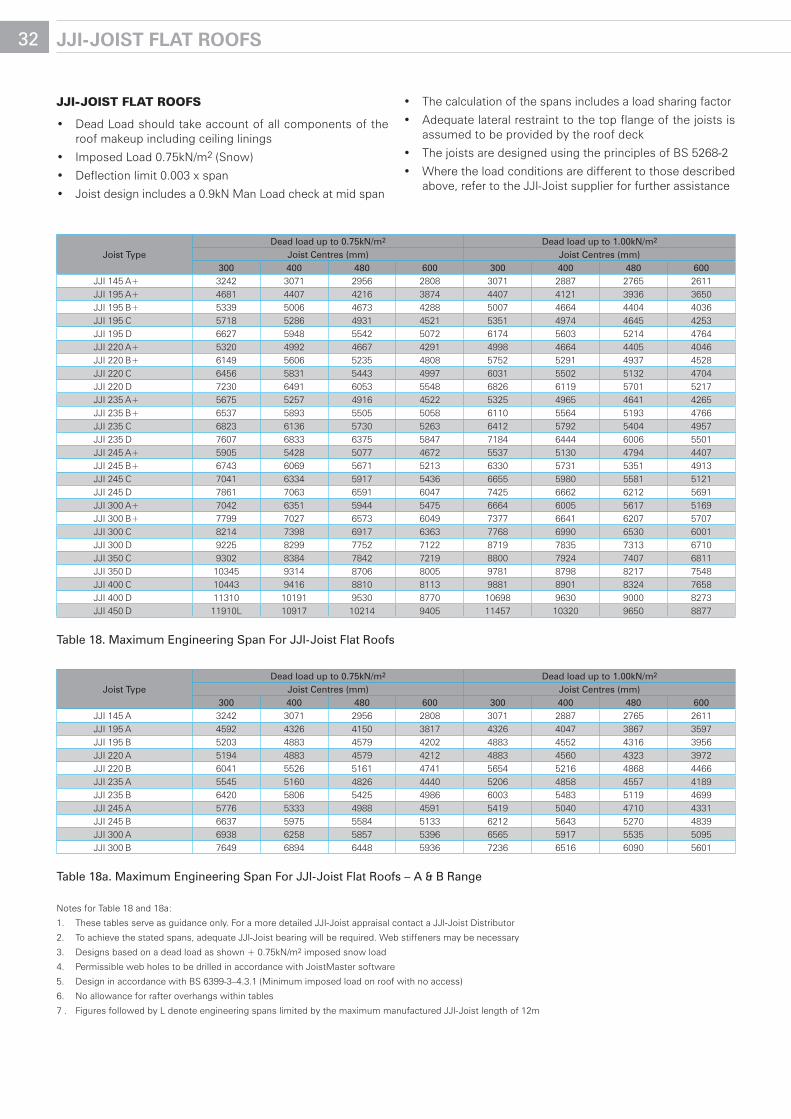
Joist typeDead load up to 0.75kN/m2 Dead load up to 1.00kN/m2
Joist Centres (mm) Joist Centres (mm)300 400 480 600 300 400 480 600
JJI 145 A+ 3242 3071 2956 2808 3071 2887 2765 2611JJI 195 A+ 4681 4407 4216 3874 4407 4121 3936 3650JJI 195 B+ 5339 5006 4673 4288 5007 4664 4404 4036JJI 195 C 5718 5286 4931 4521 5351 4974 4645 4253JJI 195 D 6627 5948 5542 5072 6174 5603 5214 4764JJI 220 A+ 5320 4992 4667 4291 4998 4664 4405 4046JJI 220 B+ 6149 5606 5235 4808 5752 5291 4937 4528JJI 220 C 6456 5831 5443 4997 6031 5502 5132 4704JJI 220 D 7230 6491 6053 5548 6826 6119 5701 5217JJI 235 A+ 5675 5257 4916 4522 5325 4965 4641 4265JJI 235 B+ 6537 5893 5505 5058 6110 5564 5193 4766JJI 235 C 6823 6136 5730 5263 6412 5792 5404 4957JJI 235 D 7607 6833 6375 5847 7184 6444 6006 5501JJI 245 A+ 5905 5428 5077 4672 5537 5130 4794 4407JJI 245 B+ 6743 6069 5671 5213 6330 5731 5351 4913JJI 245 C 7041 6334 5917 5436 6655 5980 5581 5121JJI 245 D 7861 7063 6591 6047 7425 6662 6212 5691JJI 300 A+ 7042 6351 5944 5475 6664 6005 5617 5169JJI 300 B+ 7799 7027 6573 6049 7377 6641 6207 5707JJI 300 C 8214 7398 6917 6363 7768 6990 6530 6001JJI 300 D 9225 8299 7752 7122 8719 7835 7313 6710JJI 350 C 9302 8384 7842 7219 8800 7924 7407 6811JJI 350 D 10345 9314 8706 8005 9781 8798 8217 7548JJI 400 C 10443 9416 8810 8113 9881 8901 8324 7658JJI 400 D 11310 10191 9530 8770 10698 9630 9000 8273JJI 450 D 11910L 10917 10214 9405 11457 10320 9650 8877
table 18. Maximum Engineering Span for JJI-Joist flat roofs
Joist typeDead load up to 0.75kN/m2 Dead load up to 1.00kN/m2
Joist Centres (mm) Joist Centres (mm)300 400 480 600 300 400 480 600
JJI 145 A 3242 3071 2956 2808 3071 2887 2765 2611JJI 195 A 4592 4326 4150 3817 4326 4047 3867 3597JJI 195 B 5203 4883 4579 4202 4883 4552 4316 3956JJI 220 A 5194 4883 4579 4212 4883 4560 4323 3972JJI 220 B 6041 5526 5161 4741 5654 5216 4868 4466JJI 235 A 5545 5160 4826 4440 5206 4858 4557 4189JJI 235 B 6420 5806 5425 4986 6003 5483 5119 4699JJI 245 A 5776 5333 4988 4591 5419 5040 4710 4331JJI 245 B 6637 5975 5584 5133 6212 5643 5270 4839JJI 300 A 6938 6258 5857 5396 6565 5917 5535 5095JJI 300 B 7649 6894 6448 5936 7236 6516 6090 5601
table 18a. Maximum Engineering Span for JJI-Joist flat roofs – A & B range
Notes for Table 18 and 18a:
1. These tables serve as guidance only. For a more detailed JJI-Joist appraisal contact a JJI-Joist Distributor
2. To achieve the stated spans, adequate JJI-Joist bearing will be required. Web stiffeners may be necessary
3. Designs based on a dead load as shown + 0.75kN/m2 imposed snow load
4. Permissible web holes to be drilled in accordance with JoistMaster software
5. Design in accordance with BS 6399-3–4.3.1 (Minimum imposed load on roof with no access)
6. No allowance for rafter overhangs within tables
7 . Figures followed by L denote engineering spans limited by the maximum manufactured JJI-Joist length of 12m
32 JJI-JoIsT FlaT rooFs
JJI-JoIst Flat rooFs
• DeadLoadshouldtakeaccountofallcomponentsoftheroof makeup including ceiling linings
• ImposedLoad0.75kN/m2 (Snow)
• Deflectionlimit0.003xspan
• Joistdesignincludesa0.9kNManLoadcheckatmidspan
• Thecalculationofthespansincludesaloadsharingfactor
• Adequatelateralrestrainttothetopflangeofthejoistsisassumed to be provided by the roof deck
• ThejoistsaredesignedusingtheprinciplesofBS5268-2
• Wheretheloadconditionsaredifferenttothosedescribedabove, refer to the JJI-Joist supplier for further assistance
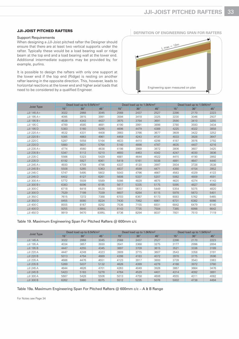
Joist typeDead load up to 0.5kN/m2 Dead load up to 1.0kN/m2 Dead load up to 1.5kN/m2
15˚ 30˚ 45˚ 15˚ 30˚ 45˚ 15˚ 30˚ 45˚JJI 145 A+ 3022 2868 3045 2568 2437 2527 2286 2170 2223JJI 195 A+ 4095 3915 3991 3594 3418 3325 3230 3046 2937JJI 195 B+ 4538 4343 4437 3975 3784 3691 3590 3410 3255JJI 195 C 4789 4585 4691 4190 3991 3898 3780 3593 3434JJI 195 D 5383 5160 5295 4696 4479 4389 4225 4022 3858JJI 220 A+ 4532 4331 4408 3983 3786 3677 3609 3422 3252JJI 220 B+ 5085 4863 4961 4459 4243 4131 4033 3828 3647JJI 220 C 5287 5058 5164 4633 4410 4298 4187 3976 3792JJI 220 D 5880 5631 5764 5140 4898 4787 4635 4407 4216JJI 235 A+ 4774 4560 4638 4198 3989 3872 3806 3607 3425JJI 235 B+ 5347 5112 5210 4693 4463 4342 4247 4030 3836JJI 235 C 5566 5323 5429 4881 4644 4522 4415 4190 3992JJI 235 D 6192 5927 6061 5419 5161 5038 4891 4647 4440JJI 245 A+ 4930 4709 4786 4337 4120 3997 3934 3728 3538JJI 245 B+ 5508 5265 5363 4837 4599 4471 4380 4154 3952JJI 245 C 5747 5495 5602 5043 4796 4667 4563 4329 4122JJI 245 D 6402 6127 6261 5606 5337 5207 5062 4809 4591JJI 300 A+ 5772 5509 5589 5086 4828 4675 4620 4374 4143JJI 300 B+ 6383 6096 6195 5617 5335 5175 5095 4827 4580JJI 300 C 6718 6418 6528 5907 5613 5449 5354 5075 4820JJI 300 D 7529 7199 7339 6607 6284 6115 5978 5673 5401JJI 350 C 7615 7272 7388 6703 6367 6173 6083 5762 5465JJI 350 D 8455 8080 8224 7430 7062 6861 6731 6382 6066JJI 400 C 8555 8167 8292 7536 7155 6931 6842 6479 6140JJI 400 D 9255 8840 8395L 8143 7735 7504 7385 6998 6642JJI 450 D 9919 9470 8395L 8736 8294 8037 7931 7510 7119
table 19. Maximum Engineering Span for Pitched rafters @ 600mm c/c
Joist typeDead load up to 0.5kN/m2 Dead load up to 1.0kN/m2 Dead load up to 1.5kN/m2
15˚ 30˚ 45˚ 15˚ 30˚ 45˚ 15˚ 30˚ 45˚JJI 145 A 3022 2868 3045 2568 2437 2527 2286 2170 2223JJI 195 A 4034 3857 3930 3541 3368 3275 3177 2996 2894JJI 195 B 4447 4255 4345 3897 3709 3615 3521 3336 3189JJI 220 A 4447 4249 4323 3909 3715 3607 3543 3358 3191JJI 220 B 5013 4794 4889 4398 4183 4072 3978 3775 3596JJI 235 A 4686 4476 4551 4123 3917 3800 3739 3543 3363JJI 235 B 5269 5037 5132 4626 4399 4278 4188 3972 3780JJI 245 A 4844 4626 4701 4263 4049 3926 3867 3664 3476JJI 245 B 5423 5183 5278 4764 4529 4401 4314 4092 3891JJI 300 A 5687 5428 5506 5013 4758 4606 4555 4311 4082JJI 300 B 6262 5980 6075 5512 5235 5076 5002 4738 4494
table 19a. Maximum Engineering Span for Pitched rafters @ 600mm c/c – A & B range
For Notes see Page 34
33JJI-JoIsT PITched raFTers
JJI-JoIst pItched raFters
Support requirementsWhen designing a JJI-Joist pitched rafter the Designer should ensure that there are at least two vertical supports under the rafter. Typically these would be a load bearing wall or ridge beam at the top end and a load bearing wall at the lower end. Additional intermediate supports may be provided by, for example, purlins.
It is possible to design the rafters with only one support at the lower end if the top end (Ridge) is resting on another rafter leaning in the opposite direction. This, however, leads to horizontal reactions at the lower end and higher axial loads that need to be considered by a qualified Engineer.
Engineering span measured on plan
L max = 12m
deFInITIon oF enGIneerInG sPan For raFTers
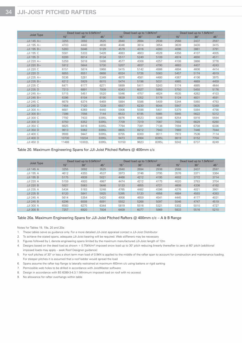
Joist typeDead load up to 0.5kN/m2 Dead load up to 1.0kN/m2 Dead load up to 1.5kN/m2
15˚ 30˚ 45˚ 15˚ 30˚ 45˚ 15˚ 30˚ 45˚JJI 145 A+ 3255 3092 3525 2840 2694 2938 2568 2437 2597JJI 195 A+ 4703 4440 4608 4046 3814 3854 3639 3430 3415JJI 195 B+ 5283 5046 5129 4579 4316 4283 4096 3861 3791JJI 195 C 5581 5333 5426 4883 4603 4528 4356 4107 4005JJI 195 D 6289 6014 6134 5517 5249 5109 4974 4690 4511JJI 220 A+ 5259 5018 5086 4577 4308 4257 4108 3866 3776JJI 220 B+ 5912 5644 5730 5207 4937 4790 4683 4407 4243JJI 220 C 6151 5874 5968 5415 5142 4986 4894 4606 4414JJI 220 D 6855 6551 6668 6024 5726 5563 5457 5174 4919JJI 235 A+ 5536 5281 5349 4870 4581 4480 4367 4106 3975JJI 235 B+ 6212 5929 6015 5474 5196 5031 4965 4669 4459JJI 235 C 6471 6177 6271 5699 5411 5243 5174 4885 4644JJI 235 D 7213 6891 7009 6343 6027 5850 5750 5450 5176JJI 245 A+ 5715 5451 5520 5046 4757 4624 4535 4262 4103JJI 245 B+ 6396 6104 6190 5639 5352 5179 5124 4831 4591JJI 245 C 6678 6374 6469 5884 5586 5409 5344 5060 4793JJI 245 D 7454 7120 7239 6557 6230 6044 5947 5635 5349JJI 300 A+ 6681 6369 6440 5906 5598 5401 5379 5084 4798JJI 300 B+ 7398 7056 7144 6533 6195 5985 5945 5622 5312JJI 300 C 7792 7433 8395L 6876 6523 6306 6254 5916 5594JJI 300 D 8750 8352 8395L 7709 7319 7087 7002 6629 6280JJI 350 C 8825 8416 8395L 7794 7391 7138 7094 6708 6336JJI 350 D 9813 9362 8395L 8655 8212 7943 7869 7446 7044JJI 400 C 9908 9447 8395L 8755 8300 8011 7972 7536 7114JJI 400 D 10730 10234 8395L 9473 8984 8395L 8619 8152 7704JJI 450 D 11488 10302L 8395L 10150 9623 8395L 9242 8737 8249
table 20. Maximum Engineering Spans for JJI-Joist Pitched rafters @ 400mm c/c
Joist typeDead load up to 0.5kN/m2 Dead load up to 1.0kN/m2 Dead load up to 1.5kN/m2
15˚ 30˚ 45˚ 15˚ 30˚ 45˚ 15˚ 30˚ 45˚JJI 145 A 3255 3092 3525 2840 2694 2938 2568 2437 2597JJI 195 A 4612 4355 4537 3973 3746 3795 3576 3371 3364JJI 195 B 5175 4939 5021 4468 4212 4195 4002 3772 3714JJI 220 A 5159 4920 4987 4474 4212 4175 4020 3783 3704JJI 220 B 5827 5563 5646 5133 4855 4721 4608 4336 4182JJI 235 A 5434 5183 5248 4765 4482 4396 4276 4021 3901JJI 235 B 6120 5841 5925 5395 5120 4956 4884 4593 4393JJI 245 A 5614 5354 5420 4956 4659 4541 4445 4177 4031JJI 245 B 6296 6008 6091 5552 5268 5097 5046 4747 4519JJI 300 A 6583 6275 6344 5819 5516 5321 5302 5010 4727JJI 300 B 7257 6920 7004 6409 6077 5869 5833 5516 5210
table 20a. Maximum Engineering Spans for JJI-Joist Pitched rafters @ 400mm c/c – A & B range
Notes for Tables 19, 19a, 20 and 20a:
1. These tables serve as guidance only. For a more detailed JJI-Joist appraisal contact a JJI-Joist Distributor
2. To achieve the stated spans, adequate JJI-Joist bearing will be required. Web stiffeners may be necessary
3. Figures followed by L denote engineering spans limited by the maximum manufactured JJI-Joist length of 12m
4. Designs based on the dead load as shown + 0.75kN/m2 imposed snow load up to 30° pitch reducing linearly thereafter to zero at 60° pitch (additional
imposed loads may apply – seek Roof Designer guidance)
5. For roof pitches of 30° or less a short term man load of 0.9kN is applied to the middle of the rafter span to account for construction and maintenance loading.
For steeper pitches it is assumed that a roof ladder would spread the load
6. Spans assume the rafter top flange is laterally restrained at maximum 400mm c/c using battens or rigid sarking
7. Permissible web holes to be drilled in accordance with JoistMaster software
8. Design in accordance with BS 6399-3-4.3.1 (Minimum imposed load on roof with no access)
9. No allowance for rafter overhangs within table
34 JJI-JoIsT PITched raFTers
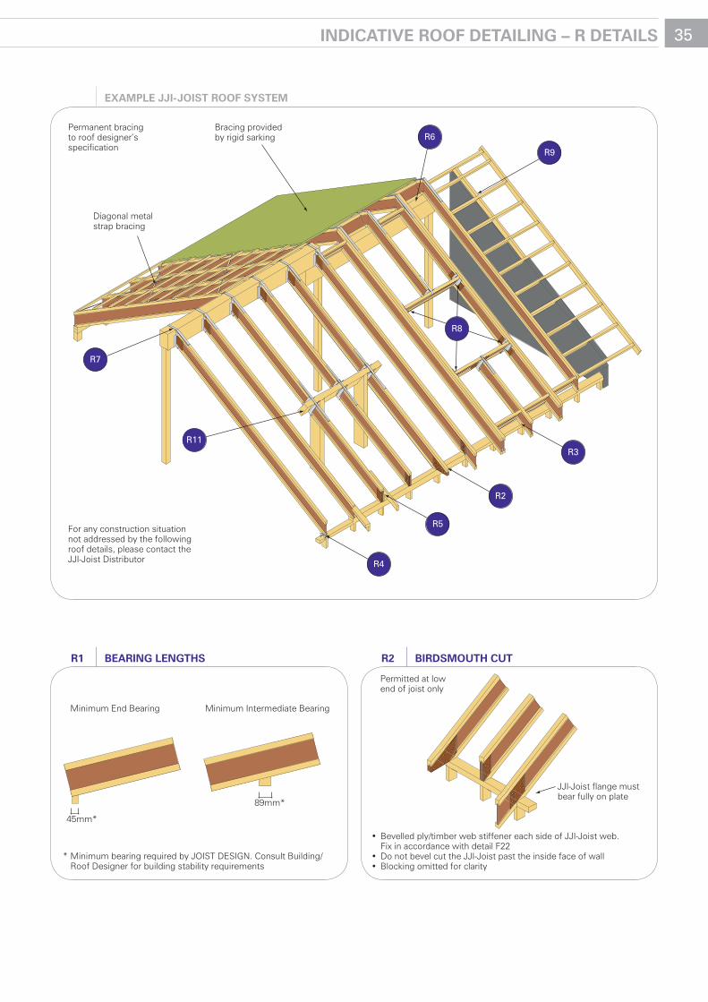
35IndIcaTIVe rooF deTaIlInG – r deTaIls
* Minimum bearing required by JOIST DESIGN. Consult Building/ Roof Designer for building stability requirements
Minimum End Bearing Minimum Intermediate Bearing
45mm*
89mm*
bearInG lenGThsr1
Permanent bracing to roof designer’s specification
For any construction situation not addressed by the following roof details, please contact the JJI-Joist Distributor
R7
R4
R5
R2
R3
R9
R6
Diagonal metal strap bracing
Bracing provided by rigid sarking
R11
R8
exaMPle JJI-JoIsT rooF sYsTeM
• Bevelled ply/timber web stiffener each side of JJI-Joist web.Fix in accordance with detail F22
• Do not bevel cut the JJI-Joist past the inside face of wall• Blocking omitted for clarity
Permitted at low end of joist only
JJI-Joist flange must bear fully on plate
bIrdsMouTh cuTr2
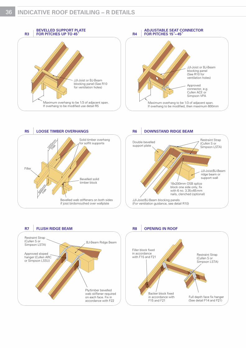
36 IndIcaTIVe rooF deTaIlInG – r deTaIls
JJI-Joist or BJ-Beamblocking panel (See R10 for ventilation holes)
Maximum overhang to be 1/3 of adjacent span. If overhang to be modified use detail R5
beVelled suPPorT PlaTe For PITches uP To 45˚r3
JJI-Joist or BJ-Beam blocking panel (See R10 for ventilation holes)
Maximum overhang to be 1/3 of adjacent span. If overhang to be modified, then maximum 600mm
Approved connector, e.g. Cullen ACE or Simpson VPA
adJusTable seaT connecTor For PITches 15˚– 45˚r4
Filler
Bevelled web stiffeners on both sides if joist birdsmouthed over wallplate
Solid timber overhang for soffit supports
Bevelled solid timber block
1200
mm
max
600m
m m
ax
loose TIMber oVerhanGsr5
Approved sloped hanger (Cullen ARC or Simpson LSSU)
Restraint Strap (Cullen S or Simpson LSTA)
Ply/timber bevelled web stiffener required on each face. Fix in accordance with F22
BJ-Beam Ridge Beam
Flush rIdGe beaMr7
Double bevelled support plate
JJI-Joist/BJ-Beam blocking panels(For ventilation guidance, see detail R10)
Restraint Strap(Cullen S or Simpson LSTA)
JJI-Joist/BJ-Beam ridge beam or support wall
18x200mm OSB splice block one side only, fix with 6 no. 3.35x65mm nails, clenched (optional)
downsTand rIdGe beaMr6
Backer block fixed in accordance with F15 and F21
Restraint Strap (Cullen S or Simpson LSTA)
Full depth face fix hanger (See detail F14 and F21)
Filler block fixed in accordance with F15 and F21
oPenInG In rooFr8
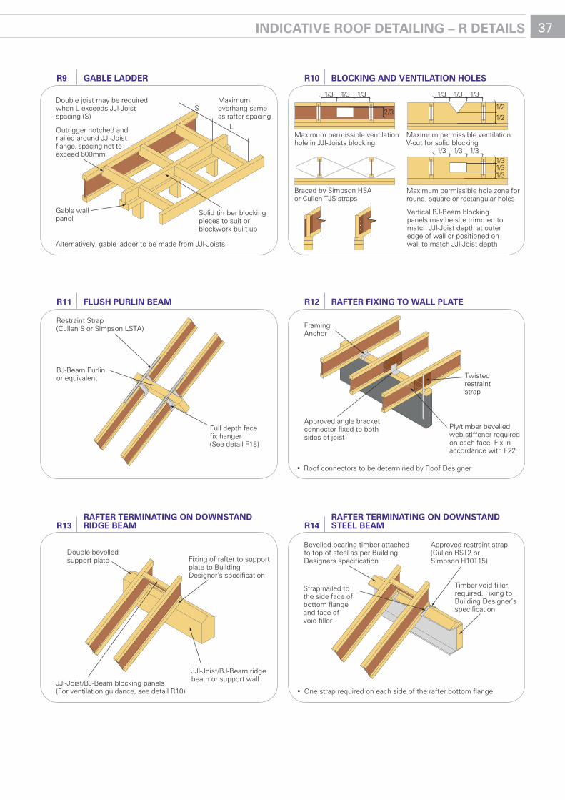
37IndIcaTIVe rooF deTaIlInG – r deTaIls
Gable wallpanel
Double joist may be required when L exceeds JJI-Joistspacing (S)
Outrigger notched and nailed around JJI-Joist flange, spacing not to exceed 600mm
Alternatively, gable ladder to be made from JJI-Joists
Solid timber blocking pieces to suit or blockwork built up
Maximum overhang same as rafter spacing
S
L
Gable ladderr9
Hope you had a good break in the snow.
Vertical BJ-Beam blocking panels may be site trimmed to match JJI-Joist depth at outer edge of wall or positioned on wall to match JJI-Joist depth
Braced by Simpson HSA or Cullen TJS straps
Maximum permissible ventilation V-cut for solid blocking
Maximum permissible ventilation hole in JJI-Joists blocking
Maximum permissible hole zone for round, square or rectangular holes
2/3
1/3 1/3 1/3
1/2
1/2
1/31/31/3
1/3 1/3 1/3
1/3 1/3 1/3
blockInG and VenTIlaTIon holesr10
BJ-Beam Purlinor equivalent
Restraint Strap (Cullen S or Simpson LSTA)
Full depth facefix hanger (See detail F18)
Flush PurlIn beaMr11
Double bevelled support plate
JJI-Joist/BJ-Beam blocking panels(For ventilation guidance, see detail R10)
JJI-Joist/BJ-Beam ridge beam or support wall
Fixing of rafter to support plate to Building Designer’s specification
raFTer TerMInaTInG on downsTand rIdGe beaMr13
Twistedrestraint strap
Approved angle bracket connector fixed to both sides of joist
Ply/timber bevelled web stiffener required on each face. Fix in accordance with F22
• Roof connectors to be determined by Roof Designer
FramingAnchor
raFTer FIxInG To wall PlaTer12
Approved restraint strap (Cullen RST2 or Simpson H10T15)
Timber void filler required. Fixing to Building Designer’s specification
• One strap required on each side of the rafter bottom flange
Bevelled bearing timber attached to top of steel as per Building Designers specification
Strap nailed to the side face of bottom flange and face of void filler
raFTer TerMInaTInG on downsTand sTeel beaMr14
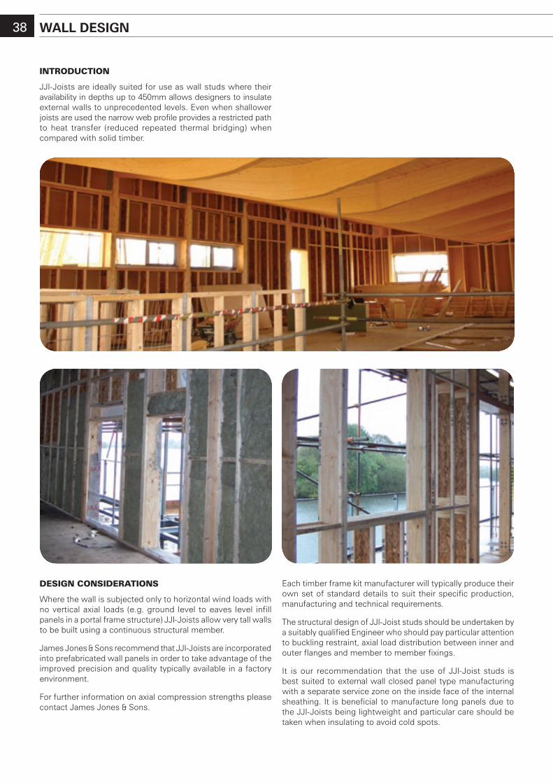
38 wall desIGn
desIgn consIderatIons
Where the wall is subjected only to horizontal wind loads with no vertical axial loads (e.g. ground level to eaves level infill panels in a portal frame structure) JJI-Joists allow very tall walls to be built using a continuous structural member.
James Jones & Sons recommend that JJI-Joists are incorporated into prefabricated wall panels in order to take advantage of the improved precision and quality typically available in a factory environment.
For further information on axial compression strengths please contact James Jones & Sons.
IntroductIon
JJI-Joists are ideally suited for use as wall studs where their availability in depths up to 450mm allows designers to insulate external walls to unprecedented levels. Even when shallower joists are used the narrow web profile provides a restricted path to heat transfer (reduced repeated thermal bridging) when compared with solid timber.
Each timber frame kit manufacturer will typically produce their own set of standard details to suit their specific production, manufacturing and technical requirements.
The structural design of JJI-Joist studs should be undertaken by a suitably qualified Engineer who should pay particular attention to buckling restraint, axial load distribution between inner and outer flanges and member to member fixings.
It is our recommendation that the use of JJI-Joist studs is best suited to external wall closed panel type manufacturing with a separate service zone on the inside face of the internal sheathing. It is beneficial to manufacture long panels due to the JJI-Joists being lightweight and particular care should be taken when insulating to avoid cold spots.
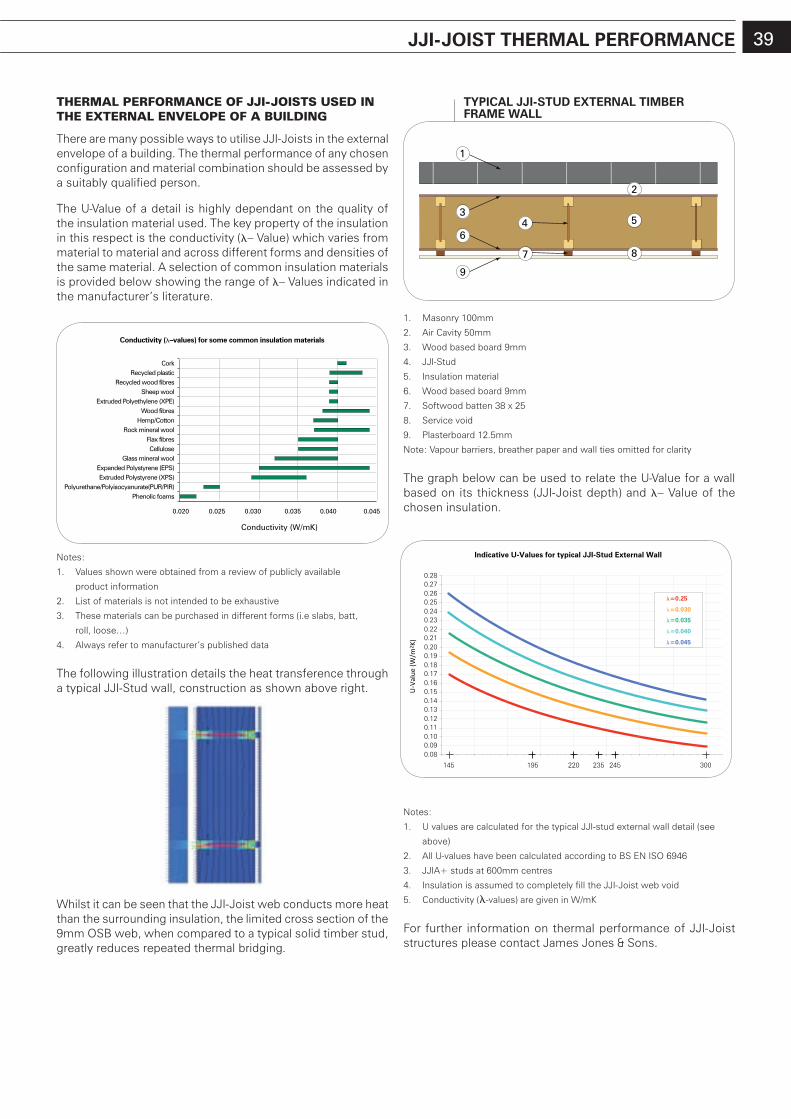
39
thermal perFormance oF JJI-JoIsts used In the external envelope oF a BuIldIng
There are many possible ways to utilise JJI-Joists in the external envelope of a building. The thermal performance of any chosen configuration and material combination should be assessed by a suitably qualified person.
The U-Value of a detail is highly dependant on the quality of the insulation material used. The key property of the insulation in this respect is the conductivity (– Value) which varies from material to material and across different forms and densities of the same material. A selection of common insulation materials is provided below showing the range of – Values indicated in the manufacturer’s literature.
Notes:
1. Values shown were obtained from a review of publicly available
product information
2. List of materials is not intended to be exhaustive
3. These materials can be purchased in different forms (i.e slabs, batt,
roll, loose…)
4. Always refer to manufacturer’s published data
The following illustration details the heat transference through a typical JJI-Stud wall, construction as shown above right.
Whilst it can be seen that the JJI-Joist web conducts more heat than the surrounding insulation, the limited cross section of the 9mm OSB web, when compared to a typical solid timber stud, greatly reduces repeated thermal bridging.
1. Masonry 100mm
2. Air Cavity 50mm
3. Wood based board 9mm
4. JJI-Stud
5. Insulation material
6. Wood based board 9mm
7. Softwood batten 38 x 25
8. Service void
9. Plasterboard 12.5mm
Note: Vapour barriers, breather paper and wall ties omitted for clarity
The graph below can be used to relate the U-Value for a wall based on its thickness (JJI-Joist depth) and – Value of the chosen insulation.
Notes:
1. U values are calculated for the typical JJI-stud external wall detail (see
above)
2. All U-values have been calculated according to BS EN ISO 6946
3. JJIA+ studs at 600mm centres
4. Insulation is assumed to completely fill the JJI-Joist web void
5. Conductivity (-values) are given in W/mK
For further information on thermal performance of JJI-Joist structures please contact James Jones & Sons.
JJI-JoIsT TherMal PerForMance 39
Conductivity (–values) for some common insulation materials
CorkRecycled plastic
Recycled wood fibresSheep wool
Extruded Polyethylene (XPE)Wood fibres
Hemp/CottonRock mineral wool
Flax fibresCellulose
Glass mineral woolExpanded Polystyrene (EPS)Extruded Polystyrene (XPS)
Polyurethane/Polyisocyanurate(PUR/PIR)Phenolic foams
0.020 0.025 0.030 0.035 0.040 0.045
Conductivity (W/mK)
1
34 5
6
7
2
8
9
TYPIcal JJI-sTud exTernal TIMber FraMe wall
0.080.090.100.110.120.130.140.150.160.170.180.190.200.210.220.230.240.250.260.270.28
Indicative U-Values for typical JJI-Stud External Wall
U-V
alue
(W/m
2 K)
=0.25
=0.030
=0.035
=0.040
=0.045
145 195 220 235 245 300
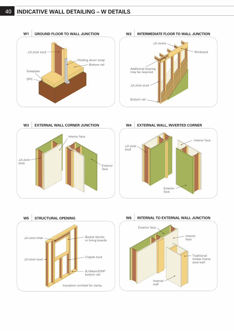
40 IndIcaTIVe wall deTaIlInG – w deTaIls
Interior face
Exteriorface
JJI-Joist stud
exTernal wall corner JuncTIonw3
Interior face
JJI-Joist stud
Exteriorface
exTernal wall, InVerTed cornerw4
Exterior face
Internalwall
Traditionaltimber framestud wall
Interiorface
InTernal To exTernal wall JuncTIonw6
JJI-Joist stud
Additional bracing may be required
Rimboard
Bottom rail
JJI-Joists
InTerMedIaTe Floor To wall JuncTIonw2
JJI-Joist lintel
Insulation omitted for clarity
Backer blocks or lining boards
BJ-Beam/EWPbottom rail
JJI-Joist studCripple stud
sTrucTural oPenInGw5
JJI-Joist stud
DPC
Holding down strap
Bottom rail
Soleplate
Ground Floor To wall JuncTIonw1
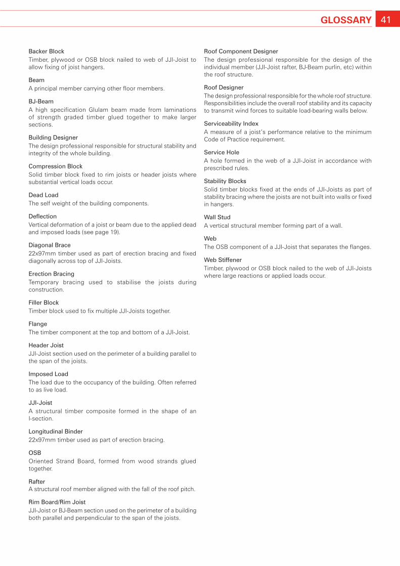
41GlossarY
Backer BlockTimber, plywood or OSB block nailed to web of JJI-Joist to allow fixing of joist hangers.
BeamA principal member carrying other floor members.
BJ-BeamA high specification Glulam beam made from laminations of strength graded timber glued together to make larger sections.
Building DesignerThe design professional responsible for structural stability and integrity of the whole building.
Compression BlockSolid timber block fixed to rim joists or header joists where substantial vertical loads occur.
Dead LoadThe self weight of the building components.
DeflectionVertical deformation of a joist or beam due to the applied dead and imposed loads (see page 19).
Diagonal Brace22x97mm timber used as part of erection bracing and fixed diagonally across top of JJI-Joists.
Erection BracingTemporary bracing used to stabilise the joists during construction.
filler BlockTimber block used to fix multiple JJI-Joists together.
flangeThe timber component at the top and bottom of a JJI-Joist.
header JoistJJI-Joist section used on the perimeter of a building parallel to the span of the joists.
Imposed LoadThe load due to the occupancy of the building. Often referred to as live load.
JJI-JoistA structural timber composite formed in the shape of an I-section.
Longitudinal Binder22x97mm timber used as part of erection bracing.
oSBOriented Strand Board, formed from wood strands glued together.
rafterA structural roof member aligned with the fall of the roof pitch.
rim Board/rim JoistJJI-Joist or BJ-Beam section used on the perimeter of a building both parallel and perpendicular to the span of the joists.
roof Component DesignerThe design professional responsible for the design of the individual member (JJI-Joist rafter, BJ-Beam purlin, etc) within the roof structure.
roof DesignerThe design professional responsible for the whole roof structure. Responsibilities include the overall roof stability and its capacity to transmit wind forces to suitable load-bearing walls below.
Serviceability IndexA measure of a joist’s performance relative to the minimum Code of Practice requirement.
Service holeA hole formed in the web of a JJI-Joist in accordance with prescribed rules.
Stability BlocksSolid timber blocks fixed at the ends of JJI-Joists as part of stability bracing where the joists are not built into walls or fixed in hangers.
Wall StudA vertical structural member forming part of a wall.
WebThe OSB component of a JJI-Joist that separates the flanges.
Web StiffenerTimber, plywood or OSB block nailed to the web of JJI-Joists where large reactions or applied loads occur.
JJI-Joists distribution
JJI-Joists, BJ-Beam and associated connection hardware are readily available through a national network of specialists who have staff specifically trained in the design and installation of JJI-Joist systems.
• JJI-JoistDistributorsarespecificallychosenbecauseoftheir professionalism and close relationships with builders
• JJI-JoistDistributorsarestrategically locatedthroughoutthe UK and Ireland
• StocksofJJI-JoistsareheldbyallJJI-JoistDistributors
• Distributors employ technical staff who are trained in the use of JoistMaster and FloorMaster programs
• Deliveriesandleadtimesarekepttoaminimumduetothe location of the JJI-Joist Distributor and the production facility being based in the UK
• Many JJI-Joist Distributors have several depots each with trained staff capable of nationwide distribution
Timber Systems DivisionGreshop Industrial EstateForres ScotlandIV36 2GW
t: 01309 671111f: 01309 671720e: [email protected]: www.jji-joists.co.uk
For further details please contact:
Revised February 2010