Embed Size (px)
Citation preview

1
Project title: P1: Control methodologies of Distributed Generation for enhanced network stability and control – (UQ)
End of Year Report 30 July 2009
Tareq Aziz, Sudarshan Dahal, Zhao Yang Dong, Mithulan Nadarajah, Tapan Saha
The University of Queensland, St. Lucia, Brisbane
Contact Address: Prof Tapan Saha
Email: [email protected], Telephone: 07 3365 3962.

Summary of End of year report 2009 of Project P1: Control methodologies of distributed generation for enhanced network stability and
control
The first part of the project investigates the modelling and stability aspects of power distribution system with distributed generation (DGs). The voltage stability and oscillatory stability of the system in presence of DGs are investigated. Both static and dynamic models of DGs are discussed. The DGs are modelled as power factor controlled source and voltage controlled source depending on the nature of available energy resources. In this report, voltage and small signal stability have been analysed with different DG’s located in a selected 16 bus distribution system. It is a 23 kV, 100MVA balanced system with 3 feeders and 13 sectionalizing branches. The principle reason behind choosing this modified 16 bus system for starting the static voltage stability analysis is its simplicity and easy to visualise the impact of distributed generation sources. While locating the DGs in this system, we have considered four different kinds of DGs namely: variable speed wind turbine, fixed speed wind turbine, solar panel in aggregated form and bagasse based cogeneration plants which targets all the possible generation technologies (i.e. synchronous, asynchronous and static generation). A number of simulations were carried out to understand the impact of static voltage stability and small signal stability on the locations of different DG units in a selected distribution system. The MATLAB and PowerFactory software have been used for simulation.
The scenario analysis was performed with no penetration, 10% penetration and 20% penetration of DGs. The significant penetration of distributed generation reverses the power flow and the network is no longer a passive circuit supplying loads. The static voltage stability study with PV and QV analysis clearly shows that the penetration of DG’s in the existing power system has an influence on voltage profile, loading limit and reactive power margin of the system. The voltage magnitude of the buses increases with the increase in DG penetration, which is more significant in a stressed system. The loading limit reaches to 3.15 than the base case 2.98 with DG penetration of 20%. As most of the DGs are consuming reactive power, locating the placement of reactive power sources will be vital to maintain the system voltage stability. Future work will include design of control methodologies with these issues to improve the voltage stability of the network.
The oscillatory stability is important for safe dynamic operation of the system. Oscillatory stability is studied by linearizing the nonlinear dynamic equation and evaluating the eigenvalues. The location of eigenvalues on complex plane gives the information about the stability of the system. In a system, if the distributed generators are added, they contribute the damping and reduce the magnitude of low frequency oscillation. It will improve the small signal performance of the power system. These results are obtained with fixed value of load and generation. When the power system is subjected to intermittent generation, the scenario might be different. These will be studied in the next part of this study.
This study highlights the significance of DG’s with respect to their behaviours in power system stability studies. Moreover, the complexities of these issues with respect to QV curve and PV curve has been outlined with future direction of work. Preliminary study with small signal stability shows some remarkable advantage in respect of small signal stability study with DG’s connected in the low voltage network. However, it is premature to put any conclusive statement and further studies with more complicated issues are planned for the future work.

2
Introduction
In this report power system models of commonly used distributed generator (DG) units along with the models for network connecting the DGs and loads are investigated in details. Their suitability for voltage stability (both static and dynamic) and small signal stability have been investigated. A number of MATLAB tools have also been developed to understand the impact of static voltage stability and small signal stability on the locations of different DG units in a selected distribution system. Their suitability for the PowerFactory software has also been investigated.
Distributed generators can be either asynchronous or synchronous and both types are described with their mathematical equations. Other than this, an aggregated solar panel modelling concept is also briefly discussed. DG’s considered in this report includes:‐
(a) Asynchronous Generator: There are two commonly used wind generator models available for the stability studies. These are:‐
• Squirrel Cage Induction Generator (Fixed Speed Wind Turbines) • Doubly Fed Induction generator Model
(b) Synchronous Generators
(c) Photovoltaic Generation
Electricity network elements are considered and their models are also described, which includes transformer and transmission lines. Load modelling plays an important role for explaining the system stability with DG’s and hence, a comprehensive load modelling aspect is presented in this report. Load models are traditionally classified into two broad categories: static models and dynamic models. Static load models are relevant to load flow studies as these express active and reactive steady state powers as functions of the bus voltages (at a given fixed frequency). Dynamic load models are useful for inter‐area oscillations, voltage stability and long term stability. Once the models are presented with appropriate mathematical relationships, and properly understood, these models will be developed for stability analysis. In this report static load flow based voltage stability has been analysed with different DG’s located in a selected distribution system. PV and QV analysis have been performed for the select power distribution system. Small signal Stability has been investigated briefly for the distribution system with DG’s in the network. Further work is planned in year 2 and 3, where all other models will be sequentially developed and further extended, where necessary.
This report first outlines the modelling aspects of different elements of sub‐transmission and distribution network. The second part of the report provides results from the static voltage stability analyses with PV and QV curves and finally some insight into the small signal stability is also introduced. For completeness, the comprehensive literature review of the work is attached in the appendix C.
A. Models of Power System Elements Specifically Focussed with DG’s
For stability studies power systems are modelled using a set of differential equations and a set of algebraic equations as given in (2.1).
; (1.0)
Where x is a vector of state variables, y is a vector of algebraic variables, l and p are uncontrollable and controllable parameter respectivley.
3
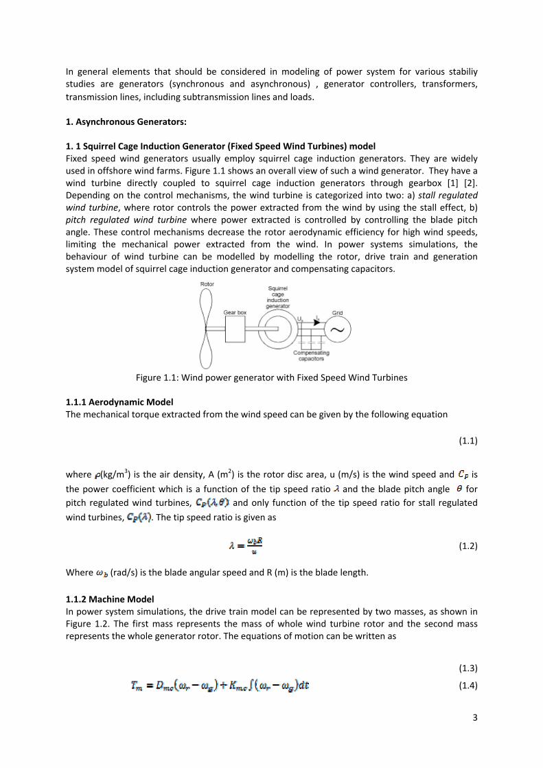
In general elements that should be considered in modeling of power system for various stabiliy studies are generators (synchronous and asynchronous) , generator controllers, transformers, transmission lines, including subtransmission lines and loads. 1. Asynchronous Generators: 1. 1 Squirrel Cage Induction Generator (Fixed Speed Wind Turbines) model Fixed speed wind generators usually employ squirrel cage induction generators. They are widely used in offshore wind farms. Figure 1.1 shows an overall view of such a wind generator. They have a wind turbine directly coupled to squirrel cage induction generators through gearbox [1] [2]. Depending on the control mechanisms, the wind turbine is categorized into two: a) stall regulated wind turbine, where rotor controls the power extracted from the wind by using the stall effect, b) pitch regulated wind turbine where power extracted is controlled by controlling the blade pitch angle. These control mechanisms decrease the rotor aerodynamic efficiency for high wind speeds, limiting the mechanical power extracted from the wind. In power systems simulations, the behaviour of wind turbine can be modelled by modelling the rotor, drive train and generation system model of squirrel cage induction generator and compensating capacitors.
Figure 1.1: Wind power generator with Fixed Speed Wind Turbines
1.1.1 Aerodynamic Model The mechanical torque extracted from the wind speed can be given by the following equation
(1.1)
where (kg/m3) is the air density, A (m2) is the rotor disc area, u (m/s) is the wind speed and is
the power coefficient which is a function of the tip speed ratio and the blade pitch angle for pitch regulated wind turbines, and only function of the tip speed ratio for stall regulated
wind turbines, . The tip speed ratio is given as
(1.2)
Where (rad/s) is the blade angular speed and R (m) is the blade length.
1.1.2 Machine Model In power system simulations, the drive train model can be represented by two masses, as shown in Figure 1.2. The first mass represents the mass of whole wind turbine rotor and the second mass represents the whole generator rotor. The equations of motion can be written as
(1.3)
(1.4)

4
(1.5)
rJ gJwT gTrω gω
mT
mcK
mcD
Figure 1.2: Drive Train Model[1]
Where are the speed and inertia of the wind turbine rotor and generator, is the
generator mechanical torque, is the generator electrical torque and and are the
stiffness and damping of the mechanical coupling. The squirrel cage induction generator can be represented by third order model. [3‐8]. The dynamic equations of per unit generator model are expressed as
(1.6)
(1.7)
Where and are back emfs of the induction generator, and and are the stator currents.
The generated electrical torque is:
(1.8)
The active and reactive powers of generated are:
(1.9)
(1.10)
In (1.6) and (1.7), is the transient open circuit time constant and is transient reactance, which
can be written as (1.11)
(1.12)
Where, and are stator and rotor resistances, and are the stator and rotor leakage
reactance, and is magnetizing reactance.
The total current injected by the generator into the network is given by
(1.13)
(1.14)
Where, is the reactance of the compensating capacitors, and are capacitors current
components, and are the wind turbine generation voltage components.
5
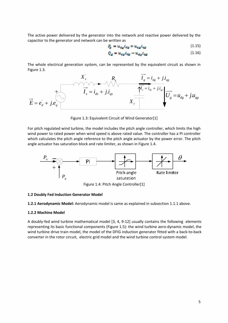
The active power delivered by the generator into the network and reactive power delivered by the capacitor to the generator and network can be written as
(1.15)
(1.16)
The whole electrical generation system, can be represented by the equivalent circuit as shown in Figure 1.3.
+
'' . qd ejeE +=
qsdss ijiI .+= qcdcc ijiI .+=
qgdgg ijiI .+=
qgdgg ujuU .+=cX
'sX
sR
Figure 1.3: Equivalent Circuit of Wind Generator[1]
For pitch regulated wind turbine, the model includes the pitch angle controller, which limits the high wind power to rated power when wind speed is above rated value. The controller has a PI controller which calculates the pitch angle reference to the pitch angle actuator by the power error. The pitch angle actuator has saturation block and rate limiter, as shown in Figure 1.4.
nP
gP
+− θ
Figure 1.4: Pitch Angle Controller[1]
1.2 Doubly Fed Induction Generator Model
1.2.1 Aerodynamic Model: Aerodynamic model is same as explained in subsection 1.1.1 above.
1.2.2 Machine Model
A doubly‐fed wind turbine mathematical model [3, 4, 9‐12] usually contains the following elements representing its basic functional components (Figure 1.5): the wind turbine aero‐dynamic model, the wind turbine drive train model, the model of the DFIG induction generator fitted with a back‐to‐back converter in the rotor circuit, electric grid model and the wind turbine control system model.

6
Mechanicalshaft model
Turbinerotor model
Electric gridmodel
wv tm
gω
gm
tωmabci
mabcu
Wind turbine control system
rabcisrp,ˆ sap*
rabcutω
gω Generator drivemodel
*sap *
srp
Figure 1.5: Block diagram of the dynamic model of a wind turbine connected to the electric grid[12]
The characteristic feature of the dependence of the wind turbine power upon the wind speed has been illustrated in Figure. 1.6 (the nominal power being 2 MW).
0 5 10 15 20 25-500
0
500
1000
1500
2000
2500
vw [m/s]
P t [kW
]
Figure 1.6: Static characteristic of wind turbine mechanical power tP as a function of mean wind
speed[12]
The differential equation dynamic model system coefficients are as follows: tJ – wind turbine
inertia; gJ – induction generator inertia; vtD – wind turbine shaft damping coefficient; vtK – wind
turbine shaft stiffness coefficient; and mki – gearbox transmission ratio.
Model input values are as follows: wv – wind speed by means of which, based on the static
characteristic as shown in Figure. 1, the wind turbine power is obtained; tm – wind turbine torque,
and gm – induction generator electromagnetic moment obtained from the DFIG dynamic model.
Wind turbine dynamic model states variables, at the same time representing the model output values, are as follows: tϑ – wind turbine rotor angle; gϑ – generator rotor angle: tω – wind turbine
rotational speed; gω – generator rotor rotational speed.
The wind turbine drive train model includes the inertia of the wind turbine, generator and gearbox connecting the two rotating shafts. The common equation of the turbine and generator shaft mechanical motion connects the drive train system dynamic model to that of the DFIG.

7
Induction machine dynamic operation modes have been described by means of a system of voltage differential equations for the stator and rotor coils respectively. The DFIG mathematical model expressed in unit values and αβ coordinate system are as follows:
αααα ψψψ
srs
rs
s
s uTk
Tdtd
++−= ''1
,
ββββ ψψ
ψsr
s
rs
s
s uTk
Tdtd
++−= ''
1,
αβααα ωψψψψ
rrrr
sr
sr uTT
kdt
d+−−= ''
1
ββαββ ψωψψ
ψrr
rrs
r
sr uTT
kdt
d+−+= ''
1,
Rotor and stator feed voltage vector components are:
sas uu =α ,
( )scsbs uuu −=3
1β ,
rar uu =α ,
( )rcrbr uuu −=3
1β .
The stator and rotor current vector components, expressed by means of the known magnetic flux components, are as follows:
ααα ψψ rr
ss
ss L
kL
i ''1
−= ,
βββ ψψ rr
ss
ss L
kL
i ''1
−= ,
,1'' ααα ψψ rr
ss
rr LL
ki +−=
βββ ψψ rr
ss
rr LL
ki ''1
+−= .
The generator electromagnetic moment, at the same time representing the input value of the wind turbine two‐mass model, is:
αββα ψψ sssse iim −= . (1.20)
The following are the parameters as occurring in the equations from (1.1) to (1.3) :
(1.17)
(1.18)
(1.19)

8
s's LL σ= , r
'r LL σ= ,
rs
m
LLL2
1−=σ ,s
ms L
Lk = ,
r
mr L
Lk = ,
s
's'
s RL
T = and r
'r'
r RLT = .
The induction generator stator active and reactive power momentary value is obtained by multiplying the stator voltage vector by conjugated‐complex value of the stator current vector, as illustrated below:
ββαα sssssa iuiup += , (1.21)
βααβ sssssr iuiup −= . (1.22)
The DFIG rotor active power momentary value may be calculated in a similar way:
ββαα rrrrra iuiup += . (1.23)
The momentary value of the rotor reactive power equals zero.
The momentary values of the induction generator stator and rotor current may be obtained from the αβ coordinate system components by means of the following equations:
22βα sss iii += ,
22βα rrr iii += .
Input values of voltage equation system (1.1) represent the components of the stator feed voltage vector αβsu and rotor feed vector αβru , whereas the status variables, being at the same time the
system output values, act as stator and rotor flux vectors. The output values are represented by the generator electromagnetic flux, stator and rotor power, as well as stator and rotor current vector components. Synchronous generator models are described in the following section.
2. Synchronous Generator Model
2.1 Shaft Power Model
Synchronous machines run under constant shaft power input and constant speed. The shaft power is provided based on the available energy resources. In case of CHP plants, the shaft power is provided with be from different energy conversion technology. Common CHP plant types are:
a) Gas turbine CHP plants using the waste heat in the flue gas of gas turbine b) Steam turbine CHP plants that use the heating system as the system condenser for the
steam turbine. c) Molten‐carbonate fuel cells that have a hot exhaust, very suitable for heating.
The output power model varies according to the type of the fuel used to drive the shaft of the synchronous generator. The comprehensive explanations can be found in [13, 14].
2.2 Machine Model
The dynamic model of synchronous machine is well established in the literature. In stability simulations, the stator transients are neglected. The detailed model of synchronous machine with stator transients neglected in described in Appendix A.1.
(1.24)

9
3. Photovoltaic generation unit 3.1 Solar irradiation model The main building blocks of the PV system are an array of PV panels, a forced‐commutated Voltage‐Sourced Converter (VSC), a three‐phase, LC, interface Filter, and the interface transformer Tr1[15]. Figure 3.1 shows a single‐line schematic diagram of a PV system which is interfaced with a distribution network at a Point of Common Coupling (PCC).
Figure 3.1: Single‐line diagram of a grid‐connected PV system [15]
The overall model of a PV system consists of three sets of equations describing dynamics of the PV array, the DC‐link voltage, and the AC‐side current of the PV system. The model of the uncontrolled PV system in addition to those of the controllers constitutes a model for the controlled PV system. Assuming that all PV cells are identical, subjected to the same irradiation, equally biased, and of the same temperature, the PV array current can be approximately described by the following equation [16]:
(3.1)
The photovoltaic current, Iph, depends on the irradiation level and the cell temperature as:
(3.2)
is the cell reverse saturation current, which varies with temperature according to the equation:
(3.3)
The model parameters include : Unit charge,
k: Boltzmann’s constant : p‐n junction ideality factor : Cells temperature : Cell reference temperature,
: Reverse saturation current at : Band‐gap energy of a cell
: Cell short‐circuit current at the reference temperature and radiation,
10
: Temperature coefficient,
S: Irradiation level in .
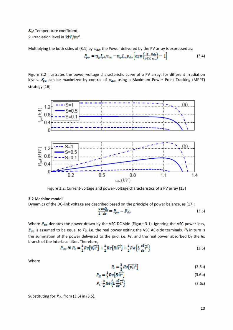
Multiplying the both sides of (3.1) by , the Power delivered by the PV array is expressed as:
(3.4)
Figure 3.2 illustrates the power‐voltage characteristic curve of a PV array, for different irradiation levels. can be maximized by control of , using a Maximum Power Point Tracking (MPPT)
strategy [16].
Figure 3.2: Current‐voltage and power‐voltage characteristics of a PV array [15]
3.2 Machine model Dynamics of the DC‐link voltage are described based on the principle of power balance, as [17]:
(3.5)
Where denotes the power drawn by the VSC DC‐side (Figure 3.1). Ignoring the VSC power loss,
is assumed to be equal to , i.e. the real power exiting the VSC AC‐side terminals. in turn is
the summation of the power delivered to the grid, i.e. Ps, and the real power absorbed by the RL branch of the interface filter. Therefore,
(3.6)
Where
(3.6a)
(3.6b)
= (3.6c)
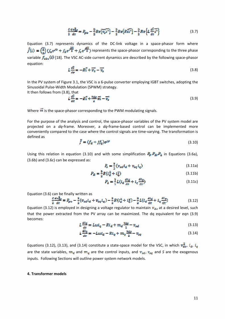
Substituting for from (3.6) in (3.5),
11
(3.7)
Equation (3.7) represents dynamics of the DC‐link voltage in a space‐phasor form where
represents the space‐phasor corresponding to the three phase
variable [18]. The VSC AC‐side current dynamics are described by the following space‐phasor
equation:
(3.8)
In the PV system of Figure 3.1, the VSC is a 6‐pulse converter employing IGBT switches, adopting the Sinusoidal Pulse‐Width Modulation (SPWM) strategy. It then follows from (3.8), that
(3.9)
Where is the space‐phasor corresponding to the PWM modulating signals. For the purpose of the analysis and control, the space‐phasor variables of the PV system model are projected on a dq‐frame. Moreover, a dq‐frame‐based control can be implemented more conveniently compared to the case where the control signals are time‐varying. The transformation is defined as
(3.10)
Using this relation in equation (3.10) and with some simplification in Equations (3.6a),
(3.6b) and (3.6c) can be expressed as: (3.11a)
(3.11b)
(3.11c)
Equation (3.6) can be finally written as
(3.12)
Equation (3.12) is employed in designing a voltage regulator to maintain at a desired level, such
that the power extracted from the PV array can be maximized. The dq equivalent for eqn (3.9) becomes:
(3.13)
(3.14)
Equations (3.12), (3.13), and (3.14) constitute a state‐space model for the VSC, in which , ,
are the state variables, and are the control inputs, and , and S are the exogenous
inputs. Following Sections will outline power system network models. 4. Transformer models
12
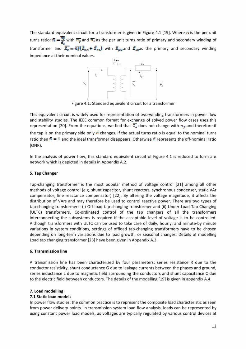
The standard equivalent circuit for a transformer is given in Figure 4.1 [19]. Where is the per unit
turns ratio: with and as the per unit turns ratio of primary and secondary winding of
transformer and with and as the primary and secondary winding
impedance at their nominal values.
1:n ez
sipi
svtvpv
Figure 4.1: Standard equivalent circuit for a transformer
This equivalent circuit is widely used for representation of two‐winding transformers in power flow and stability studies. The IEEE common format for exchange of solved power flow cases uses this representation [20]. From the equations, we find that does not change with and therefore if
the tap is on the primary side only changes. If the actual turns ratio is equal to the nominal turns ratio then and the ideal transformer disappears. Otherwise represents the off‐nominal ratio (ONR). In the analysis of power flow, this standard equivalent circuit of Figure 4.1 is reduced to form a π network which is depicted in details in Appendix A.2.
5. Tap Changer Tap‐changing transformer is the most popular method of voltage control [21] among all other methods of voltage control (e.g. shunt capacitor, shunt reactors, synchronous condenser, static VAr compensator, line reactance compensator) [22]. By altering the voltage magnitude, it affects the distribution of VArs and may therefore be used to control reactive power. There are two types of tap‐changing transformers: (i) Off‐load tap‐changing transformer and (ii) Under Load Tap Changing (ULTC) transformers. Co‐ordinated control of the tap changers of all the transformers interconnecting the subsystems is required if the acceptable level of voltage is to be controlled. Although transformers with ULTC can be used to take care of daily, hourly, and minute‐by minute variations in system conditions, settings of offload tap‐changing transformers have to be chosen depending on long‐term variations due to load growth, or seasonal changes. Details of modelling Load tap changing transformer [23] have been given in Appendix A.3. 6. Transmission line A transmission line has been characterized by four parameters: series resistance R due to the conductor resistivity, shunt conductance G due to leakage currents between the phases and ground, series inductance L due to magnetic field surrounding the conductors and shunt capacitance C due to the electric field between conductors. The details of the modelling [19] is given in appendix A.4.
7. Load modelling 7.1 Static load models In power flow studies, the common practice is to represent the composite load characteristic as seen from power delivery points. In transmission system load flow analysis, loads can be represented by using constant power load models, as voltages are typically regulated by various control devices at

13
the delivery points. In distribution systems, voltages vary widely along system feeders as there are fewer voltage control devices; therefore, the V–I characteristics of load are more important in distribution system load flow studies [24] than that of the transmission system. Load models are traditionally classified into two broad categories: static models and dynamic models. Dynamic load models are not important in load flow studies. Static load models, on the other hand, are relevant to load flow studies as these express active and reactive steady state powers as functions of the bus voltages (at a given fixed frequency). These are typically categorized as follows [25].
• Constant impedance load model (constant Z): A static load model where the power varies with the square of the voltage magnitude. It is also referred to as constant admittance load model.
• Constant current load model (constant I): A static load model where the power varies directly with voltage magnitude.
• Constant power load model (constant P): A static load model where the power does not vary with changes in voltage magnitude. It is also known as constant MVA load model.
• Exponential load model: A static load model that represents the power relationship to voltage as an exponential equation in the following way:
(7.1)
(7.2)
where and stand for the real and reactive powers consumed at a reference voltage . The
exponents α and β depend on the type of load that is being represented, e.g., for constant power load models α =β =0, for constant current load models α =β =1 and for constant impedance load models α =β =2.
• Polynomial load model: A static load model that represents the power‐voltage relationship as a polynomial equation of voltage magnitude. It is usually referred to as the ZIP model, as it is made up of three different load models:
• Constant impedance (Z), constant current (I ) and constant power (P). The real and reactive power characteristics of the ZIP load model are given by
(7.3)
(7.4)
Where, and and are the real and reactive power consumed
at a reference voltage . In this report, three types of static load models, i.e., constant power,
constant current and constant impedance, are considered to demonstrate their effect on voltage regulation calculations in distribution systems. The studies presented in this report can be readily extended to other load models as well. 7.2 Dynamic load models Studies of inter‐area oscillations, voltage stability and long term stability often require load dynamics to be modelled. Study of systems with large concentration of motors also requires representation of load dynamics. Typically motor consume 60 to 70% of the total energy supplied by a power system

14
[19]. Therefore, the dynamics attributable to motors are usually the most significant aspects of dynamic characteristics of system loads. The dynamic loads which are basically considered as induction motors are represented by a similar model based on Stanley's equations [26, 27] and written in the following form in d‐q reference frame: Stator flux linkages:
(7.5)
(7.6)
Rotor flux linkages:
(7.7)
(7.8)
The stator voltages in terms of the d and q components are
(7.9)
(7.10)
And the rotor voltages are (7.11)
(7.12)
The instantaneous power input to the stator is
(7.13)
Similarly the instantaneous power input to the rotor is
(7.14)
The electromagnetic torque is
(7.15)
The acceleration equation
(7.16)
Where the symbols have the following meanings:
= rotor speed in mechanical radians per second = stator and rotor phase resistance
= Flux linkage in direct and quadrature axis, = direct and quadrature axis voltages
= direct and quadrature axis currents, J = polar moment of inertia of the rotor and the
connected load, = Electromagnetic and load torque
p = differential operator A composite load model [19] which allows the representation of the wide range of characteristics exhibited by the various load components is shown in the Figure 6.1. The model has the provision for representing aggregations of small induction motors, large induction motors, static load characteristics, discharge lighting, thermostatically controlled loads [28], transformer saturation effects and shunt capacitors.

15
Figure 7.1: Composite static and dynamic load model [19]

16
B. Static Load Flow Based Voltage Stability & Small Signal Stability Analyses
1. Static Load Flow Based Voltage Stability:
A system experiences a state of voltage instability when there is a progressive or uncontrollable drop in voltage magnitude after a disturbance, increase in load demand and change in operating condition. The main factor, which causes these unacceptable voltage profiles, is the inability of the distribution system to meet the demand for reactive power. Under normal operating conditions, the bus voltage magnitude (V) increases as Q injected at the same bus is increased. However, when V of any one of the system’s buses decreases with the increase in Q for that same bus, the system is said to be unstable [19]. Although the voltage instability is a localised problem, its impact on the system can be widespread as it depends on the relationship between transmitted P, injected Q and receiving end V. These relationships play an important role in the stability analysis and can be displayed graphically using PV curve and QV curve. In our study of voltage stability with penetration of DG into the system we have derived these curves using MatLab 7.7 and Power Factory 14.0 which will be depicted in the results section of the report.
Before dealing with the details of the stability issues and results, the available distribution system and our test system is described in brief, this will lead us to power flow study with DG penetration. 1.1 System description: 1.1.1 Available Radial Distribution systems: Table 1.1 shows a list of commonly available balanced three phase radial distribution system test cases [29] from the technical literature for comparing and reporting research results on problems such as power flow solution, network reconfiguration, capacitor placement, load balancing, contingency analysis etc. Table 1.2 provides some details of the first four systems i.e. 16 bus, 30 bus, 33 bus and 94 bus systems in terms of load type, nominal voltage and some other parameters.
Table 1.1: List of available balanced three phase radial distribution systems test cases Serial Test Case Number of buses/Feeders/Tie
Switches Ref. and Comments
1 16 Bus 16/3/3 [30] 2 30 Bus 30/1/1 This test case is known as the "IEEE 30
bus" [31] 3 33 Bus 33/1/5 [32] 4 94 Bus 94/11/13 [33] 5 143 Bus 143/8/21 Modified to 8 feeders by removal of the
super‐feeder [34] 6 204 Bus 204/3/15 Modified to 3 feeders by removal of the
super‐feeder [34] 7 880 Bus 880/7/27 Hypothetical test case created using
data from test cases 5 and 6 [35]

17
Table 1.2: Principle features of some balanced three phase radial distribution systems test cases
Features 16 Bus 30 Bus 33 Bus 94 Bus
Load Types a. All spot loads b. balanced load
a. All spot loads b. balanced load c. Load factors for feeders and sub feeders connected to different buses are given
a. All spot loads b.. balanced load
a. All spot loads b. balanced load
No. Of Feeders 3 1 1 11
Nominal voltage 23 kV 11kV 12.66kV 11.4kV
No. of sectionalizing branches
13 29 32 83
No. of Tie switches 3 1 5 13
In recent years many software have been developed for the analysis of unbalanced three‐phase radial distribution feeders. These softwares use wide variety of iterative techniques with many simplifying assumptions for line and load models to sophisticated formulations. With different softwares available there is a need for benchmark test feeders so that the results from various softwares can be compared. IEEE Distribution System Analysis Subcommittee has revised the four radial test feeders that were originally presented at the 1991 IEEE PES Winter Meeting. A fifth test feeder (IEEE 4 node test feeder) has been added to focus on transformer connections. The primary purpose of this test feeder is to provide a simple system for the testing of all possible three‐phase transformer connections. The principle features of the available IEEE radial distribution test feeders [36] are listed in appendix B .
Figure 1.1: 16 Bus 3 feeder example system
18
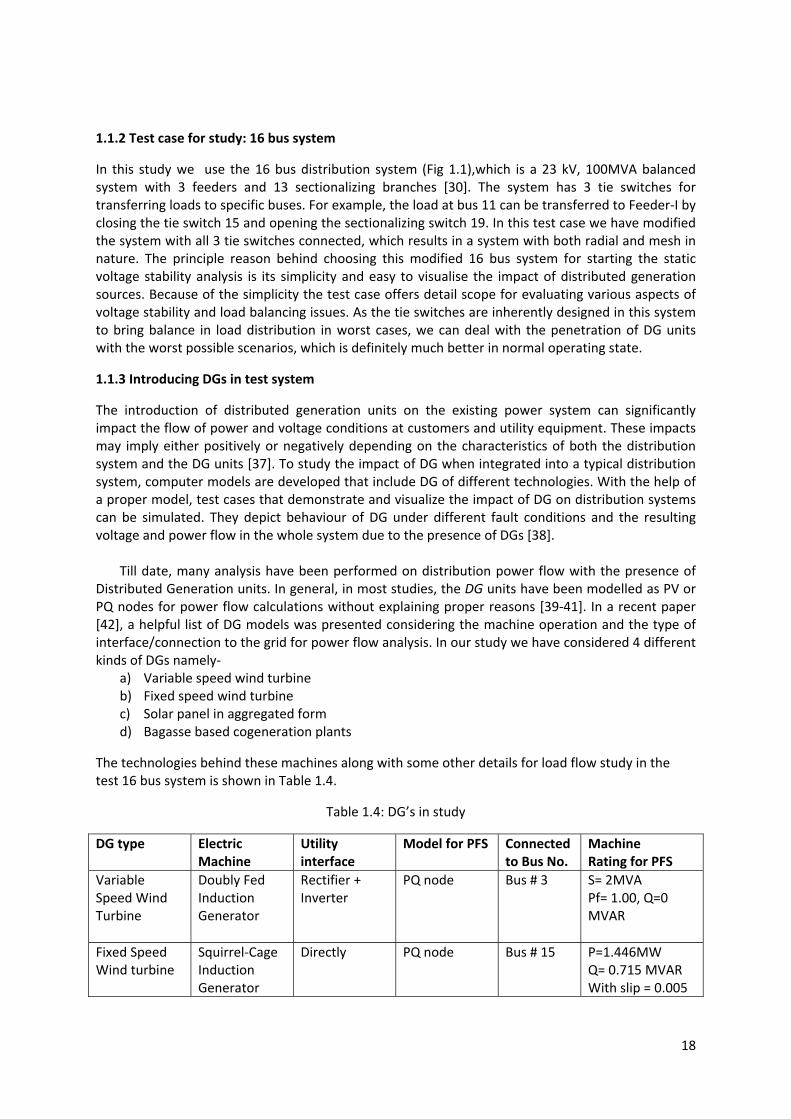
1.1.2 Test case for study: 16 bus system
In this study we use the 16 bus distribution system (Fig 1.1),which is a 23 kV, 100MVA balanced system with 3 feeders and 13 sectionalizing branches [30]. The system has 3 tie switches for transferring loads to specific buses. For example, the load at bus 11 can be transferred to Feeder‐I by closing the tie switch 15 and opening the sectionalizing switch 19. In this test case we have modified the system with all 3 tie switches connected, which results in a system with both radial and mesh in nature. The principle reason behind choosing this modified 16 bus system for starting the static voltage stability analysis is its simplicity and easy to visualise the impact of distributed generation sources. Because of the simplicity the test case offers detail scope for evaluating various aspects of voltage stability and load balancing issues. As the tie switches are inherently designed in this system to bring balance in load distribution in worst cases, we can deal with the penetration of DG units with the worst possible scenarios, which is definitely much better in normal operating state.
1.1.3 Introducing DGs in test system
The introduction of distributed generation units on the existing power system can significantly impact the flow of power and voltage conditions at customers and utility equipment. These impacts may imply either positively or negatively depending on the characteristics of both the distribution system and the DG units [37]. To study the impact of DG when integrated into a typical distribution system, computer models are developed that include DG of different technologies. With the help of a proper model, test cases that demonstrate and visualize the impact of DG on distribution systems can be simulated. They depict behaviour of DG under different fault conditions and the resulting voltage and power flow in the whole system due to the presence of DGs [38].
Till date, many analysis have been performed on distribution power flow with the presence of
Distributed Generation units. In general, in most studies, the DG units have been modelled as PV or PQ nodes for power flow calculations without explaining proper reasons [39‐41]. In a recent paper [42], a helpful list of DG models was presented considering the machine operation and the type of interface/connection to the grid for power flow analysis. In our study we have considered 4 different kinds of DGs namely‐
a) Variable speed wind turbine b) Fixed speed wind turbine c) Solar panel in aggregated form d) Bagasse based cogeneration plants
The technologies behind these machines along with some other details for load flow study in the test 16 bus system is shown in Table 1.4.
Table 1.4: DG’s in study
DG type Electric Machine
Utility interface
Model for PFS Connected to Bus No.
Machine Rating for PFS
Variable Speed Wind Turbine
Doubly Fed Induction Generator
Rectifier + Inverter
PQ node Bus # 3 S= 2MVA Pf= 1.00, Q=0 MVAR
Fixed Speed Wind turbine
Squirrel‐Cage Induction Generator
Directly PQ node Bus # 15 P=1.446MW Q= 0.715 MVAR With slip = 0.005
19
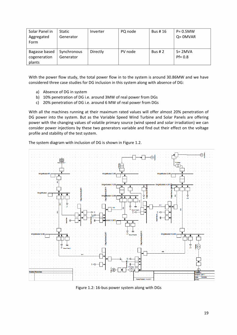
Solar Panel in Aggregated Form
Static Generator
Inverter PQ node Bus # 16 P= 0.5MW Q= 0MVAR
Bagasse based cogeneration plants
Synchronous Generator
Directly PV node Bus # 2 S= 2MVA Pf= 0.8
With the power flow study, the total power flow in to the system is around 30.86MW and we have considered three case studies for DG inclusion in this system along with absence of DG:
a) Absence of DG in system b) 10% penetration of DG i.e. around 3MW of real power from DGs c) 20% penetration of DG i.e. around 6 MW of real power from DGs
With all the machines running at their maximum rated values will offer almost 20% penetration of DG power into the system. But as the Variable Speed Wind Turbine and Solar Panels are offering power with the changing values of volatile primary source (wind speed and solar irradiation) we can consider power injections by these two generators variable and find out their effect on the voltage profile and stability of the test system.
The system diagram with inclusion of DG is shown in Figure 1.2.
Figure 1.2: 16‐bus power system along with DGs

20
1.2 Impacts of DG penetration: Results and Analysis
1.2.1 Voltage Profile:
The significant penetration of distributed generation reverses the power flow and the network is no longer a passive circuit supplying loads. It becomes an active system with power flows and voltages determined by the generation as well as the loads. In these cases, the generator exports excessive power to all the loads on the system to which it is connected. The surplus power is transferred into a higher voltage system. If an adjacent load absorbs the output from an embedded generator, then the impact on the distribution network voltage is likely to be advantageous.
Figure 1.3 shows the voltage profile at all 16 buses with three different cases which clearly show that with inclusion of DG, voltage values at almost all the buses have a significant improvement because of the injection of real power flow near to the loads. It also improves with the increase in percentage of penetration of DG power.
(a) Voltage profile for Load injection ratio = 1
(b) Voltage profile for Load injection ratio = 1.3
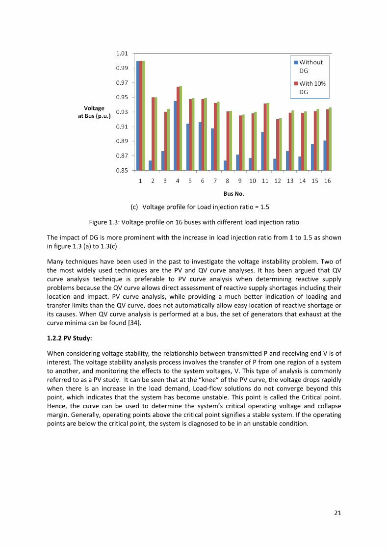
21
(c) Voltage profile for Load injection ratio = 1.5
Figure 1.3: Voltage profile on 16 buses with different load injection ratio
The impact of DG is more prominent with the increase in load injection ratio from 1 to 1.5 as shown in figure 1.3 (a) to 1.3(c).
Many techniques have been used in the past to investigate the voltage instability problem. Two of the most widely used techniques are the PV and QV curve analyses. It has been argued that QV curve analysis technique is preferable to PV curve analysis when determining reactive supply problems because the QV curve allows direct assessment of reactive supply shortages including their location and impact. PV curve analysis, while providing a much better indication of loading and transfer limits than the QV curve, does not automatically allow easy location of reactive shortage or its causes. When QV curve analysis is performed at a bus, the set of generators that exhaust at the curve minima can be found [34].
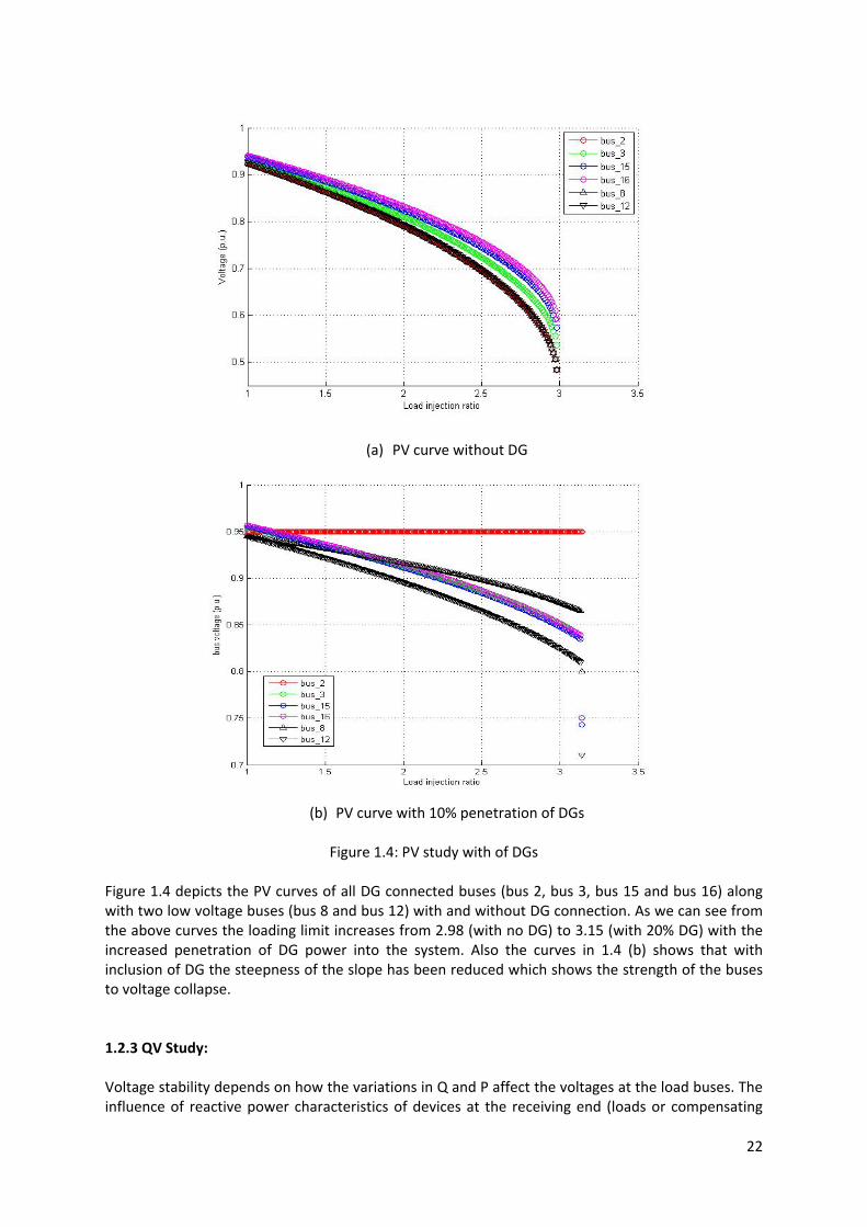
1.2.2 PV Study:
When considering voltage stability, the relationship between transmitted P and receiving end V is of interest. The voltage stability analysis process involves the transfer of P from one region of a system to another, and monitoring the effects to the system voltages, V. This type of analysis is commonly referred to as a PV study. It can be seen that at the “knee” of the PV curve, the voltage drops rapidly when there is an increase in the load demand, Load‐flow solutions do not converge beyond this point, which indicates that the system has become unstable. This point is called the Critical point. Hence, the curve can be used to determine the system’s critical operating voltage and collapse margin. Generally, operating points above the critical point signifies a stable system. If the operating points are below the critical point, the system is diagnosed to be in an unstable condition.
22
(a) PV curve without DG
(b) PV curve with 10% penetration of DGs
Figure 1.4: PV study with of DGs
Figure 1.4 depicts the PV curves of all DG connected buses (bus 2, bus 3, bus 15 and bus 16) along with two low voltage buses (bus 8 and bus 12) with and without DG connection. As we can see from the above curves the loading limit increases from 2.98 (with no DG) to 3.15 (with 20% DG) with the increased penetration of DG power into the system. Also the curves in 1.4 (b) shows that with inclusion of DG the steepness of the slope has been reduced which shows the strength of the buses to voltage collapse.
1.2.3 QV Study: Voltage stability depends on how the variations in Q and P affect the voltages at the load buses. The influence of reactive power characteristics of devices at the receiving end (loads or compensating

23
devices) is more apparent in a QV relationship. It shows the sensitivity and variation of bus voltages with respect to reactive power injections or absorptions. A typical QV curve is usually generated by a series of load‐flow solutions. Voltage stability limit is found on the curve at the point where the derivative dQ/dV is zero. This point also defines the minimum reactive power requirement for a stable operation. An increase in Q will result an increase in voltage during normal operating conditions. Hence, if the operating point is on the right side of the curve, the system is said to be stable. Conversely, operating points in the left side of the graph are deemed to be unstable.
(a) QV curve without DG
(b) QV curve with 10% DG penetration
(c) QV curve with 20% DG penetration Figure 1.5: QV curves with different levels of DG penetration

24
Figure 1.5 plots the QV curves of the test system with three different levels of DG power injection. From Figure 1.3, it is obvious that Bus 8 is the lowest voltage bus. We selected Bus 8 for the QV curve analysis. As the penetration of the DGs is scaled up, the reactive power margin scaled up from 50MVAr to 55MVAr. Since the DGs are supplying small amount of reactive power (only by the synchronous generator at bus 2) into the system, their impact on the change of reactive power margin is not by large amount. However, as the penetration is reasonably high, the significant impact on the reactive power margin is expected.
(a) QV curve with Load injection ratio = 1
(b) QV curve with Load injection ratio = 1.3
(c) QV curve with Load injection ratio = 1.5
Figure 1.6: Shift in reactive power with increase in load
25
Figure 1.6 depicts the decrease in reactive power margin with the increase in load injection ratio from 1 to 1.5 for 20% penetration of DGs. Initially the margin was at 55MVAr which ultimately reduces to 45MVAr with increase in loading.
1.3 Summary of Voltage stability static study:
It is clearly observed that the inclusion of DG’s in the existing power system is going to impose influence on voltage profile, loading limit and reactive power margin of the system. The voltage magnitude along the buses of the system is going to increase with the increase in DG power percentage in the system which is more significant in a stressed system. The loading limit reaches to some greater extent (3.15) then the base case (2.98) with DG penetration of 20%. In some cases the changes in these parameters were not very significant (e.g. the difference in voltage levels of buses with 10% and 20% penetration figure 1.3). The primary reason for this may be the select test system. Our test (16‐bus) system was not a pure radial system with the closed tie switch connections. In case of pure radial system the effects are expected to be more prominent, which will be studied in the coming days. The most important information to be obtained from this QV curve is the reactive margin from the base case operating point to the curve minima. This reactive reserve margin generally indicates how much further the loading on the bus can be increased before its loading limit is exceeded and voltage collapse occurs. QV curve analysis can be time consuming if curves have to be found for every bus in the system and a sophisticated technique has been proposed by one of the authors of this report to alleviate this problem [43].Moreover, a number of techniques with suggested indices from the IEEE Task force [44] will be carefully investigated in coming months.
In this report, the slack bus (from the main grid) was assumed to absorb all uncertainties of nodal powers. Main grid was providing any amount of real and reactive power deficiencies from the changes in loads. It has the widest nodal power probability distributions in the system. But in real practice (if the system is isolated or even grid‐connected), there is a certain limit on real and reactive power generation by the slack bus. Hence, if real and reactive power capabilities of the slack bus are restricted, the load increasing ratio limit will be much lower than the result found in this study. Also the reactive power margin found in QV study will be changed if the reactive power generation limit is strictly maintained. As most of the DGs are consuming reactive power, locating the placement of reactive power sources will be vital to maintain the system voltage stability. Future work will include design of control methodologies with these issues to improve the stability of the network.
1.4 Bifurcation Technique in Stability Analysis
In many literatures, voltage stability analysis of a power system has been performed using bifurcation analysis. Bifurcation is obtained when a system reaches its stability limit as a parameter of the system is changed. Bifurcation studies should be done considering all system dynamics and not only voltage controls, to correctly capture all the bifurcation phenomena [45]. An overview of local bifurcation theory and its application to power system voltage stability analysis is presented in [46]. The different types of bifurcations that can be found in literatures are:
‐ Saddle node bifurcation ‐ Hopf Bifurcation (Subcritical or Supercritical) ‐ Singularity induced bifurcations ‐ Transcritical bifurcation ‐ Pitchfold bifurcation
Bifurcations that are known to appear in power system models include saddle‐node, Hopf, and singularity induced bifurcations [47]. The saddle‐node bifurcation occurs when two equilibria of the nonlinear system coalesce as a parameter is varied continuously. A Hopf bifurcation occurs when
26
a limit cycle and equilibrium coaelesce as a function of a parameter. The singularity induced bifurcation occurs in systems modelled by differential/algebraic equations (DAE’s) when the algebraic equations typically undergo a saddle‐node bifurcation.
The relation between bifurcations, their usefulness and limitations in power systems stability analysis through a thorough analysis of several examples is presented in [45]. By far the most prevalent application of the concepts and tools described has been to identify the point of collapse‐a saddle‐node bifurcation point. This does not rule out the fact that other type of bifurcations, i.e., transcritical or Hopf, do also occur in real systems, with similar catastrophic results for system (voltage) stability. The importance of Hopf bifurcation has been increasingly recognized as it has become clear that stability of the equilibrium can be lost by this mechanism well before reaching the point of collapse.
Saddle node bifurcation can be obtained simply by continuation method. This method allows to trace bifurcation manifolds (diagrams) for any type of system model; however, the technique is particularly suited to detect saddle‐node bifurcations, yielding a close approximation of the bifurcation point (singularity point) and the corresponding right eigenvector without having to actually calculate and trace the system eigenvalues and eigenvectors as the parameter changes. The problem with this approach is that it cannot detect Hopf bifurcations, nor differentiate between transcritical and pitchfork bifurcations. For the other bifurcations, one needs to check for the transversality conditions of the system at the bifurcation point, which is a costly task. The Hopf bifurcation needs of the computation of the system equilibria eigenvalues to detect the crossing of the imaginary axis, since the Jacobian does not become singular in this case; a very expensive procedure when dealing with relatively large systems. Furthermore, to discern which type of Hopf has taken place (subcritical or supercritical), one needs to run a costly transient simulation or use special techniques that take into considerations additional nonlinear terms in the system Nevertheless, for PQ load models and typically small resistive losses in the transmission system, Hopf bifurcations are unlikely to occur. Although bifurcations cannot be considered as the only cause for voltage stability problems, the effect of saddle‐node bifurcations in system stability cannot be overlooked.
Monitoring the least eigenvalues or singular value as a function of load increase may drive one to draw the wrong conclusions, since these indices present a sharp variation at the bifurcation point. This behaviour is obtained when the reactive power limits of the buses are neglected and corresponding Jacobian matrix is formed. In [48], a “well‐behaved” eigenvalue has been identified, considering the reactive power limits of the buses.
Different software tools are available for bifurcation analysis of a power system. Many literatures using the small scale power system have utilized AUTO [46]. A MatLab‐based voltage stability toolbox (VST) has been designed to analyse bifurcation and voltage stability problems in electric power systems [49]. Literature [50] has pointed out some numerical issues in the identification of singularity‐induced (SI) bifurcation points in power systems using the Voltage Stability Toolbox (VST). Depending on the system under investigation, a small step‐size provides a better chance to capture SI bifurcation, at the cost of increasing simulation time. In [51], a comprehensive educational simulation tool for power system stability studies, including static voltage stability analysis, transient stability analysis, small‐signal stability analysis, and bifurcation analysis, has been developed.
In the system consisting of induction motor loads, Hopf Bifurcation analysis has been performed. In [47], bifurcations were examined in the total dynamic system model using induction motor loads (dynamic loads) and constant power loads. In [52], bifurcations are performed for a power system model consisting of two generators feeding a load, which is represented by an induction motor in parallel with a capacitor and a combination of constant power and impedance PQ

27
load. In [53], an application of bifurcation criteria is proposed for available transfer capability (ATC) determination. The Hopf bifurcation limit has been considered for determination of the dynamic ATC including induction motors. In [54], the authors concentrate on motor stalling as a possible saddle‐node bifurcation (SNB) of equilibrium equations.
2. Small Signal Stability: A Preliminary Study
There are various oscillatory phenomena observed in a distribution system. One of the prominent oscillatory stability problems is Ferro resonance, which is caused by saturation characteristics of transformer [55‐60]. Another form of oscillation is torsional oscillation that occurs among the shaft components of an induction generator or synchronous generators[61]. The most common form of oscillation is inter‐area oscillation, which is due to the swinging of generators in one area against other area[13, 62]. The stability concerned with system oscillations is called small signal stability of the system.
Small signal stability problem within the distribution system has been overlooked in the past. It is assumed that the distribution system has higher R/X ratio and thus any electromechanical oscillations would be well damped [63]. The interactions between large synchronous generators and distributed generating resources were usually ignored in analysis. Instead, the dynamic characteristics of a distribution system were modelled by a composite load model, in which the aggregated dynamics of downstream loads were represented by induction motor[64].
With recently growing concern on environment and green‐energy, much attention is given towards installing distributed generations at a low voltage level. With all these distributed generators installed in the system, the distribution system will no longer be passive as used to be considered in the past. The electromechanical and electromagnetic phenomena are prominent in the system with these dynamic devices installed. This will impose additional constraints in the operation and control of distribution system.
2.1 Effect of Distributed Resources to Ferro‐resonance: Feero and Gish [58] has presented that abnormally high and possibly damaging overvoltages can occur on isolated feeders connected to a Distribution System Generator (DSG). The mechanisms for producing the overvoltages are based on ferro‐resonance phenomena and are extremely sensitive to types of generators, types or connections of transformers, location of capacitors or other equipment parameters. The overvoltage depends on the establishment of a harmonic resonant circuit utilizing transformer saturation characteristics, the existence of power factor correcting capacitors on the feeder and source of energy sufficient to maintain transformer saturation.
A study of the application of an induction generator (IG) in power systems is presented in[55]. The results demonstrate that, if the amount of the external reactive power source is sufficient to ensure self‐excitation of the induction generator, high and abnormal over voltages occur, which can be dangerous for the insulation integrity of the equipment, the local load and, even worse, for the maintenance personnel. In [57], it has been reported that an isolated distribution system generator (DSG) can theoretically support as much as three times the generator's rated power output in a ferro‐resonant mode provided the prime mover has the needed inertia or torque available at the abnormal isolated speed.
In [59], investigations were carried out on ferro‐resonant oscillations in a transformer‐terminated line due to an energised parallel line on the same right‐of‐way. The results reveal that with high saturation levels, chaotic ferro‐resonant oscillations are a distinct possibility due to the capacitive coupling between the parallel lines. Furthermore, the route to chaos is through a

28
sequence of quasi‐periodic oscillations. The sensitivities of the solutions with respect to the length of the de‐energised line and the proximity between the parallel lines are analysed and discussed.
The conditions under which ferro‐resonant overvoltages can occur on rural distribution systems are reviewed in [60]. Preventive or corrective measures that have been proposed are reviewed and evaluated. A guide for the selection of corrective or preventive measures on rural systems is presented.
In [56], the author discusses the types and sizes of the generators, the type and magnitude of the load, and how each affects the probability and relative severity of the ferro‐resonant overvoltage predicted. It is concluded that the best way to protect interconnected customer generators and the connected load from ferro‐resonance is to prevent or preclude the occurrence of these conditions.
Some researchers have proposed transformer‐less interfacing of distributed generators to avoid the detrimental effects on transformer into the distributed generators and system[65]. However, these technologies are not welcome in practical aspects as the alternative power electronic interfaces have some other demerits.
2.2 Effect of distributed resources on electromechanical oscillations
Small‐signal stability, often in the form of low frequency oscillations, has been found to be the limiting factor when determining power transfer capabilities in a number of power systems [13, 53, 62, 66]. In transmission system, the most concerned small signal stability issue is of the electromechanical type which leads to inter‐area oscillations. The phenomena depends on the swinging of some synchronous generators against the others[13]. However, in the distribution system, new types of generators other than synchronous generators are being introduced. These are induction generators and electronic converter based generators used for renewable energy conversion. This necessitates the analysis of the small signal stability of the system with new type of generators in a new way.
The induction machine contribution to power system oscillations is well reported in [67]. This paper investigates power system small‐signal stability, considering induction machines as dynamic elements. Linear coefficients are proposed that are convenient for both quantitative and qualitative single machine‐infinite bus studies. Modal interaction between induction machines, as well as between induction and synchronous machines, is investigated. It is shown that a large proportion of induction machines in a realistic power system significantly affect the inter‐area electromechanical mode. The impact of load modelling on oscillatory stability of power system is investigated in [68].The modal analysis of a grid‐connected doubly fed induction generator (DFIG) is presented in [61]. The change in modal properties of the DFIG with variation of for different system parameters, operating points, and grid strengths are computed and observed. The results offer a better understanding of the DFIG intrinsic dynamics, which can also be useful for control design and model justification.
The impact of electronically interfaced distributed generators in electromechanical oscillations is usually ignored by many researchers as it does not contain any rotating part. Under the new system framework, it is worthwhile to look at their impact on the system. In[69], it has been reported that an adequately designed power electronic interface can not only contribute to the system voltage and frequency control but also alleviate potential instability problems during increased loading conditions.
29
2.3 Modelling Issues for small signal stability analysis
To study ferro‐resonant conditions in the system, we need a detailed electromagnetic model of distributed generators, transformers, distribution lines and compensating and protective devices. While most of the component models are available, the dynamic model of transformer suitable for stability analysis is not available. One dynamic model is proposed in [70], but the model presented in not suitable for traditional stability simulation packages. Moreover, comprehensive EMTP simulation considering dynamics of stator and transmission lines as well is required for ferro‐resonant analysis.
The study of electromechanical oscillation does not require the stator and line transients for analysis. Since these stator and line transients are dying out faster than electromechanical oscillations, their effect on long‐term dynamics can be ignored. The comparison of considering and ignoring the stator dynamics is presented in [61]. The participation of stator in electromechanical dynamics is important only in case of extremely loaded conditions.
The load modelling also has significant contribution to small signal stability analysis. The effect of composite load model parameters on stability has been investigated in [71]. The techniques of reducing the identification of load model parameters are presented. The impact on small signal stability has been well explained in [68].
As previously discussed, ferro‐resonance is the oscillatory phenomenon mainly induced by transformer and requires complex modelling and computation of power system components. On the other hand, torsional oscillations and inter‐area oscillations require simpler modelling and comparatively less expensive computation. So, we begin with the analysis of torsional and inter‐area oscillations, which only requires electromechanical modelling of the interconnected machines.
2.4 Tools for small signal stability analysis
The system Jacobian matrix is the key element to be analysed to assess the small signal stability of a system[72, 73]. The impact of system loading and operation on small signal stability can be analysed by various computational techniques. Mostly popular tools are modal analysis, sensitivity analysis, residues and participation tools. There are different tools to evaluate eigenvalues of dynamic system. QR algorithm has been mostly used in the study of medium size system. Some modifications in QR algorithms have been done to simplify the computation while preserving the overall system characteristics[13]. Comparison of different algorithms can also be found in some literatures[13, 74].In [75], some techniques are presented for the evaluation and interpretation of eigenvalue sensitivities, in the context of the analysis and control of oscillatory stability in multi‐machine power systems. These techniques combine the numeric power of model analysis of state‐space modals with the insight that can be obtained from transfer‐function descriptions. Numerical bifurcation techniques can be used to assess the stability limit and transfer capability limits of a system. Studies with numerical bifurcation techniques can be found in many literatures. In [76] various indices are proposed and studied to detect and predict oscillatory instabilities in power systems. The available transfer capability constrained by dynamic stability utilizing the bifurcation approach is presented in [53].
The popular software tools for small signal analysis are MATLAB, Power System Toolbox (PST), PowerFactory 14, and PSS/E. Here we use MATLAB and Powerfactory.
2.5 Simulation Studies
The small signal stability is studied by observing the system responses to small disturbances. For the small perturbation studies, the nonlinear dynamic equations of the system is linearized around the operating point and the eigenvalues of system Jacobian matrix is evaluated. The small signal stability or the oscillatory stability is assessed by the observing the scattered eigenvalues on a complex plane.

30
The vertical axis is called imaginary axis and the horizontal axis is real axis. The stability of a dynamic system is ensured if all the eigenvalues lie in left side of imaginary axis. If any eigenvalue lies on the imaginary axis, the system is said to be in oscillations. The eigenvalues towards far left of the imaginary axis show the well damped oscillation modes and are not creating severe stability problems. As the eigenvalues near to the imaginary axis indicate oscillation with low damping, these eigenvalues axis are more significant from point of view of small signal stability.
2.5.1 Effect of interaction of different machines on synchronous machine.
A distribution system starts from a substation where the transmission voltage is stepped down to the distribution voltage. For preliminary study, the large interconnected transmission can be approximated by a synchronous generator of capacity of the distribution substation. The distribution loads can be approximately aggregated as a constant power load. Figure 2.1 shows the approximation of our 100 MVA, 30 MW systems by a 100 MVA synchronous generator and 30 MW load at power factor 0.8. To see the effect of penetration of distributed generation on this system, we add static generator (or photovoltaic generator) of 500 KW and induction machine (or wind generator) of 2 MW.
Figure 2.1: The sample system with synchronous machine (Results from Powerfactory)
First the eigenvalue analysis was performed with synchronous machine connected to the load. This scenario represents the case before the penetration of distributed generators. Then, static generator and induction generator were added to the system to see the effect of distributed generators on the stability of the system and on the transmission side. In all the cases, the stator transients and network transients in power system dynamic models are neglected.
Figure 2.2 shows that when induction machines are added, then certain low frequency oscillation modes are well damped. This is indicated by the left arrow showing the movement of eigenvalues when induction generators are added. Similar results are reported in [67]. Also, the addition of induction generator is contributing the damping of oscillation by adding one pole at the farthest left of imaginary axis. On the other hand, the additions of static generator reduce the frequency of oscillation as indicated by downward arrow. This closely agrees the results reported in [69]. The critical eigenvalues studied are ‐13.89 ± 0.33i and ‐0.22 ±0.07i.
In both of the above cases, the addition of distributed generators gives the positive impact on small signal stability. Here, we have assumed deterministic loads and generations. However, when the stochastic nature of loads and generations are considered, there are other oscillatory frequencies,

31
which are critical from the system stability point of view. In the future, these cases will be progressively studied.
A note on the eigenvalue at origin: It should be noted here that the dynamic model of distribution system has zero eigenvalues corresponding to the angle references of individual machines. They are not contributing to the stability of the system. These can be eliminated by converting all the machine frames into a single reference frame. Similar explanations may be found in [13, 73].
Figure 2.2: Effect of DGs on stability of synchronous machine (Results from Powerfactory)
2.5.2 The small signal stability of the system with DGs.
Now, we study the small signal stability of the system under study. Now, the distribution system is fed by infinite bus as given in Figure 1.2. The penetration and location of distributed generators are as Table 1.4. Figure 2.3 shows the eigenvalues plot for the distribution system under study (Figure 1.2). The stator transients and converter dynamics have been neglected in all the synchronous and induction machine models.
In small signal stability, we are interested in those eigenvalues which are near to imaginary axis. The enlarged view of the eigenvalue plot is shown to check whether any of the eigenvalue lies on imaginary axis. Since every eigenvalues are on left side of imaginary axis, the system is stable in steady state. It should be noted that there are some eigenvalues lying at the origin owing to reference axis of machines as explained in Subsection 2.5.1. The impact of DGs on eigenvalue movement is explained in the following subsection.

32
Figure 2.3: the eigenvalues of the distribution system with distributed generators
(Results from Powerfactory)
2.5.3 Effect of penetration of DGs on small signal stability of the system
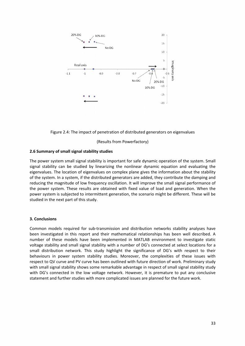
Next we see the effect of variation of penetration level of DGs into the small signal stability of a distribution system. The movement of eigenvalues with varying penetration of DGs is shown in the Figure 2.4. Since we are interested in eigenvalues near to the imaginary axis, only the eigenvalues in this subspace is highlighted.
When the penetration of DGs is increased, the eigenvalues corresponding to the low frequency oscillations move to the left. This apparently indicates that system is more stable when DG penetration is increased. The apparent stability improvement is due to increase in induction machines which is supposed to improve damping of low frequency oscillations[67]. However, in the other case, the damping of the system is reduced as penetration of DGs is increased. This is obvious in the Figure 2.4 by the movement of eigenvalues towards right along the real axis near the origin. So, this eigenvalue is critical for this system from small signal stability point of view. So, there exist a trade‐off between small signal oscillatory stability and penetration level of DGs into the distribution system. Our further study will investigate the constraints imposed by small signal stability on operation of distribution system and design of control system to mitigate the constraints.
33
Figure 2.4: The impact of penetration of distributed generators on eigenvalues
(Results from Powerfactory)
2.6 Summary of small signal stability studies
The power system small signal stability is important for safe dynamic operation of the system. Small signal stability can be studied by linearizing the nonlinear dynamic equation and evaluating the eigenvalues. The location of eigenvalues on complex plane gives the information about the stability of the system. In a system, if the distributed generators are added, they contribute the damping and reducing the magnitude of low frequency oscillation. It will improve the small signal performance of the power system. These results are obtained with fixed value of load and generation. When the power system is subjected to intermittent generation, the scenario might be different. These will be studied in the next part of this study.
3. Conclusions
Common models required for sub‐transmission and distribution networks stability analyses have been investigated in this report and their mathematical relationships has been well described. A number of these models have been implemented in MATLAB environment to investigate static voltage stability and small signal stability with a number of DG’s connected at select locations for a small distribution network. This study highlight the significance of DG’s with respect to their behaviours in power system stability studies. Moreover, the complexities of these issues with respect to QV curve and PV curve has been outlined with future direction of work. Preliminary study with small signal stability shows some remarkable advantage in respect of small signal stability study with DG’s connected in the low voltage network. However, it is premature to put any conclusive statement and further studies with more complicated issues are planned for the future work.
34
References: [1] L. M. Fernández, J. R. Saenz, and F. Jurado, "Dynamic models of wind farms with fixed speed
wind turbines," Renewable Energy, vol. 31, pp. 1203‐1230, 2006. [2] V. Bufano, M. Dicorato, A. Minoia, and M. Trovato, "Embedding wind farm generation in
power system transient stability analysis," in Power Tech, 2005 IEEE Russia, 2005, pp. 1‐7. [3] T. Ackermann, Wind power in power systems. Chichester, West Sussex, England: John Wiley,
2005. [4] V. Akhmatov, Induction generators for wind power. [Brentwood]: Multi‐Science Pub., 2005. [5] S. Foster, X. Lie, and B. Fox, "Coordinated control and operation of DFIG and FSIG based
Wind Farms," in Power Tech, 2007 IEEE Lausanne, 2007, pp. 522‐527. [6] S. S. Murthy, B. Singh, P. K. Goel, and S. K. Tiwari, "A Comparative Study of Fixed Speed and
Variable Speed Wind Energy Conversion Systems Feeding the Grid," in Power Electronics and Drive Systems, 2007. PEDS '07. 7th International Conference on, 2007, pp. 736‐743.
[7] M. Steurer, J. Langston, L. Anderson, S. Suryanarayanan, R. Meeker, and P. Ribeiro, "Voltage Sensitivity to Capacitor Switching on an Existing Fixed Speed Induction Generator Wind Farm," in Power Engineering Society General Meeting, 2007. IEEE, 2007, pp. 1‐4.
[8] A. Sumper, O. Gomis‐Bellmunt, A. Sudria‐Andreu, R. Villafafila‐Robles, and J. Rull‐Duran, "Response of Fixed Speed Wind Turbines to System Frequency Disturbances," Power Systems, IEEE Transactions on, vol. 24, pp. 181‐192, 2009.
[9] W. Chen, S. Libao, W. Liming, and N. Yixin, "Small signal stability analysis considering grid‐connected wind farms of DFIG type," in Power and Energy Society General Meeting ‐ Conversion and Delivery of Electrical Energy in the 21st Century, 2008 IEEE, 2008, pp. 1‐6.
[10] I. Erlich, J. Kretschmann, J. Fortmann, S. Mueller‐Engelhardt, and H. Wrede, "Modeling of Wind Turbines Based on Doubly‐Fed Induction Generators for Power System Stability Studies," Power Systems, IEEE Transactions on, vol. 22, pp. 909‐919, 2007.
[11] M. Kayikci and J. V. Milanovic, "Assessing Transient Response of DFIG‐Based Wind Plants—The Influence of Model Simplifications and Parameters," Power Systems, IEEE Transactions on, vol. 23, pp. 545‐554, 2008.
[12] J. Smajo, "Rotor Power Feedback Control of Wind Turbine System with Doubly‐Fed Induction Generator " Croatian Bibliographic Search.
[13] P. Kundur, "Power System Stability and Control," Electric Power Research Institute. [14] M. Thomas, "Combined heat and power, the global solution to voltage dip, pollution, and
energy efficiency," in Power System Technology, 2004. PowerCon 2004. 2004 International Conference on, 2004, pp. 1975‐1980 Vol.2.
[15] A. Y. Prajna Paramita Dash, "A mathematical model and performance evaluation for a single‐stage grid‐connected photovoltaic (PV) system," International Journal of Emerging Electric Power Systems, vol. 9, 2008.
[16] I. M. K. H. Hussein, T. Hoshino , M. Osakada, "Maximum photovoltaic power tracking: an algorithm for rapidly changing atmospheric conditions," IEE proceedings on Generation, transmission and distribution, vol. 142, pp. 59‐64, 1995.
[17] A. Yazdani and R. Iravani, "An accurate model for the DC‐side voltage control of the neutral point diode clamped converter," in Power Engineering Society General Meeting, 2006. IEEE, 2006, p. 1 pp.
[18] P. Vas, Vector control of AC machines: Oxford University Press, 1990. [19] P. Kundur, N. J. Balu, and M. G. Lauby, Power system stability and control. New York:
McGraw‐Hill, 1994. [20] W. Group, "Common Format For Exchange of Solved Load Flow Data," Power Apparatus and
Systems, IEEE Transactions on, vol. PAS‐92, pp. 1916‐1925, 1973. [21] B. M. Weedy and B. J. Cory, Electric power systems, 4th ed. Chichester ; New York: John
Wiley Sons, 1998.

35
[22] M. R. Salem, L. A. Talat, and H. M. Soliman, "Voltage control by tap‐changing transformers for a radial distribution network," Generation, Transmission and Distribution, IEE Proceedings‐, vol. 144, pp. 517‐520, 1997.
[23] C. Roman and W. Rosehart, "Complementarity model for load tap changing transformers in stability based OPF problem," Electric Power Systems Research, vol. 76, pp. 592‐599, 2006.
[24] M. H. Haque, "Load flow solution of distribution systems with voltage dependent load models," Electric Power Systems Research, vol. 36, pp. 151‐156, 1996.
[25] T. Van Cutsem and C. Vournas, Voltage Stability of Electric Power Systems: Kluwer, 1998. [26] P. C. Krause, Analysis of Electric Machinery: McGraw‐Hill, 1986. [27] O. H. Abdalla, M. E. Bahgat, A. M. Serag, and M. A. El‐Sharkawi, "Dynamic load modelling
and aggregation in power system simulation studies," in Power System Conference, 2008. MEPCON 2008. 12th International Middle‐East, 2008, pp. 270‐276.
[28] C. W. Taylor, N. J. Balu, and D. Maratukulam, Power system voltage stability. New York: McGraw Hill, 1994.
[29] "http://www.ece.ndsu.nodak.edu/~cris/reds.html." [30] S. Civanlar, J. J. Grainger, H. Yin, and S. S. H. Lee, "Distribution feeder reconfiguration for loss
reduction," Power Delivery, IEEE Transactions on, vol. 3, pp. 1217‐1223, 1988. [31] U. Eminoglu and M. H. Hocaoglu, "A new power flow method for radial distribution systems
including voltage dependent load models," Electric Power Systems Research, vol. 76, pp. 106‐114, 2005.
[32] M. E. Baran and F. F. Wu, "Network reconfiguration in distribution systems for loss reduction and load balancing," Power Delivery, IEEE Transactions on, vol. 4, pp. 1401‐1407, 1989.
[33] C.‐T. Su, C.‐F. Chang, and J.‐P. Chiou, "Distribution network reconfiguration for loss reduction by ant colony search algorithm," Electric Power Systems Research, vol. 75, pp. 190‐199, 2005.
[34] C. A. C. M.A.N. Guimaraes, "Reconfiguration of Distribution Dystems for Loss Reduction Using Tabu Search," in 15th Power System Computation Conference ‐ PSCC, 2005, pp. 1‐6.
[35] N. P. Group. [36] W. H. Kersting, "Radial distribution test feeders," Power Systems, IEEE Transactions on, vol.
6, pp. 975‐985, 1991. [37] P. P. Barker and R. W. De Mello, "Determining the impact of distributed generation on
power systems. I. Radial distribution systems," in Power Engineering Society Summer Meeting, 2000. IEEE, 2000, pp. 1645‐1656 vol. 3.
[38] L. Kojovic, "Modeling of DG to interface with distribution system," in Power Engineering Society Summer Meeting, 2002 IEEE, 2002, pp. 179‐180 vol.1.
[39] C. S. Cheng and D. Shirmohammadi, "A three‐phase power flow method for real‐time distribution system analysis," Power Systems, IEEE Transactions on, vol. 10, pp. 671‐679, 1995.
[40] G. X. Luo and A. Semlyen, "Efficient load flow for large weakly meshed networks," Power Systems, IEEE Transactions on, vol. 5, pp. 1309‐1316, 1990.
[41] Y. Zhu and K. Tomsovic, "Adaptive Power Flow Method for Distribution Systems with Dispersed Generation," Power Engineering Review, IEEE, vol. 22, pp. 72‐72, 2002.
[42] S. M. Moghaddas‐Tafreshi and E. Mashhour, "Distributed generation modeling for power flow studies and a three‐phase unbalanced power flow solution for radial distribution systems considering distributed generation," Electric Power Systems Research, vol. 79, pp. 680‐686, 2009.
[43] C. A. Aumuller and T. K. Saha, "Determination of power system coherent bus groups by novel sensitivity‐based method for voltage stability assessment," Power Systems, IEEE Transactions on, vol. 18, pp. 1157‐1164, 2003.
[44] "Voltage Stability Assessment, Procedures and Guides‐ Special Publication," IEEE Power and Energy Society, Power System Stability Subcommittee, 2000.

36
[45] C. A. Canizares, "On bifurcations, voltage collapse and load modeling," Power Systems, IEEE Transactions on, vol. 10, pp. 512‐522, 1995.
[46] H. G. Kwatny, R. F. Fischl, and C. O. Nwankpa, "Local bifurcation in power systems: theory, computation, and application," Proceedings of the IEEE, vol. 83, pp. 1456‐1483, 1995.
[47] M. A. Pai, P. W. Sauer, and B. C. Lesieutre, "Static and dynamic nonlinear loads and structural stability in power systems," Proceedings of the IEEE, vol. 83, pp. 1562‐1572, 1995.
[48] A. C. Zambroni de Souza, "Identifying a vanishing eigenvalue in voltage collapse analysis with consideration of limits," Generation, Transmission and Distribution, IEE Proceedings‐, vol. 148, pp. 263‐267, 2001.
[49] S. Ayasun, C. O. Nwankpa, and H. G. Kwatny, "Voltage Stability Toolbox for Power System Education and Research," Education, IEEE Transactions on, vol. 49, pp. 432‐442, 2006.
[50] S. Ayasun, C. O. Nwankpa, and H. G. Kwantny, "Numerical issues in the location of singularity‐induced bifurcation points," in Power Engineering Society 1999 Winter Meeting, IEEE, 1999, pp. 707‐712 vol.1.
[51] J. Xiao, B. Dai, C. Y. Chung, and K. P. Wong, "An educational simulation tool for power system stability studies," in Electric Utility Deregulation and Restructuring and Power Technologies, 2008. DRPT 2008. Third International Conference on, 2008, pp. 1180‐1185.
[52] A. H. Nayfeh, A. M. Harb, and C. Char‐Ming, "Bifurcations in a power system model," in Circuits and Systems, 1995. ISCAS '95., 1995 IEEE International Symposium on, 1995, pp. 283‐286 vol.1.
[53] A. Kumar, S. C. Srivastava, and S. N. Singh, "Available transfer capability assessment in a competitive electricity market using a bifurcation approach," Generation, Transmission and Distribution, IEE Proceedings‐, vol. 151, pp. 133‐140, 2004.
[54] C. D. Vournas and G. A. Manos, "Modelling of stalling motors during voltage stability studies," Power Systems, IEEE Transactions on, vol. 13, pp. 775‐781, 1998.
[55] M. A. Ouhrouche, X. D. Do, Q. M. Le, and R. Chaine, "EMTP based simulation of a self‐excited induction generator after its disconnection from the grid," Energy Conversion, IEEE Transactions on, vol. 13, pp. 7‐14, 1998.
[56] J. D. Bronfield, "Ferroresonant overvoltages associated with utility interconnection of independent power producers," in Southern Tier Technical Conference, 1988., Proceedings of the 1988 IEEE, 1988, pp. 22‐33.
[57] W. B. Gish, W. E. Feero, and S. Greuel, "Ferroresonance and Loading Relationships for DSG Installations," Power Delivery, IEEE Transactions on, vol. 2, pp. 953‐959, 1987.
[58] W. E. Feero and W. B. Gish, "Overvoltages Caused by DSG Operation: Synchronous and Induction Generators," Power Delivery, IEEE Transactions on, vol. 1, pp. 258‐264, 1986.
[59] R. Saravanaselvan, R. Ramanujam, K. Al‐Anbarri, and S. L. Naresh, "Ferroresonant oscillations in a transformer terminated line due to an energised parallel line on the same right‐of‐way," Generation, Transmission and Distribution, IEE Proceedings‐, vol. 152, pp. 475‐482, 2005.
[60] E. C. Lister, "Ferroresonance on Rural Distribution Systems," Industry Applications, IEEE Transactions on, vol. IA‐9, pp. 105‐111, 1973.
[61] F. Mei and B. Pal, "Modal Analysis of Grid‐Connected Doubly Fed Induction Generators," Energy Conversion, IEEE Transactions on, vol. 22, pp. 728‐736, 2007.
[62] C. Y. Chung, W. Lei, F. Howell, and P. Kundur, "Generation rescheduling methods to improve power transfer capability constrained by small‐signal stability," Power Systems, IEEE Transactions on, vol. 19, pp. 524‐530, 2004.
[63] L. Gyugyi, C. D. Schauder, and K. K. Sen, "Static synchronous series compensator: a solid‐state approach to the series compensation of transmission lines," Power Delivery, IEEE Transactions on, vol. 12, pp. 406‐417, 1997.
[64] M. Jin, H. Renmu, and D. J. Hill, "Composite load modeling via measurement approach," in Power Engineering Society General Meeting, 2006. IEEE, 2006, p. 1 pp.

37
[65] L. Maharjan, S. Inoue, H. Akagi, and J. Asakura, "A transformerless battery energy storage system based on a multilevel cascade PWM converter," in Power Electronics Specialists Conference, 2008. PESC 2008. IEEE, 2008, pp. 4798‐4804.
[66] Y. V. Makarov, D. Zhao Yang, and D. J. Hill, "On Convexity of Power Flow Feasibility Boundary," Power Systems, IEEE Transactions on, vol. 23, pp. 811‐813, 2008.
[67] B. M. Nomikos and C. D. Vournas, "Investigation of induction Machine contribution to power system oscillations," Power Systems, IEEE Transactions on, vol. 20, pp. 916‐925, 2005.
[68] Y. Mishra, Z. Y. Dong, J. Ma, and D. J. Hill, "Induction motor load impact on power system eigenvalue sensitivity analysis," Generation, Transmission & Distribution, IET, vol. 3, pp. 690‐700, 2009.
[69] J. Yao and D. Popovic, "Stability of a MV distribution network with electronically interfaced distributed generation," in Power Engineering Society General Meeting, 2004. IEEE, 2004, pp. 2162‐2167 Vol.2.
[70] T. Tran‐Quoc, L. Pierrat, A. Montmeat, and O. Huet, "A dynamic model of power transformers," in Electrotechnical Conference, 1996. MELECON '96., 8th Mediterranean, 1996, pp. 313‐316 vol.1.
[71] M. Jin, H. Dong, H. Ren‐Mu, D. Zhao‐Yang, and D. J. Hill, "Reducing Identified Parameters of Measurement‐Based Composite Load Model," Power Systems, IEEE Transactions on, vol. 23, pp. 76‐83, 2008.
[72] Y. V. Makarov, D. Zhao Yang, and D. J. Hill, "A general method for small signal stability analysis," Power Systems, IEEE Transactions on, vol. 13, pp. 979‐985, 1998.
[73] P. W. Sauer and M. A. Pai, "Power system steady‐state stability and the load‐flow Jacobian," Power Systems, IEEE Transactions on, vol. 5, pp. 1374‐1383, 1990.
[74] M. Jian, D. Zhao Yang, and Z. Pei, "Comparison of BR and QR Eigenvalue Algorithms for Power System Small Signal Stability Analysis," Power Systems, IEEE Transactions on, vol. 21, pp. 1848‐1855, 2006.
[75] F. L. Pagola, I. J. Perez‐Arriaga, and G. C. Verghese, "On sensitivities, residues and participations: applications to oscillatory stability analysis and control," Power Systems, IEEE Transactions on, vol. 4, pp. 278‐285, 1989.
[76] C. A. Canizares, N. Mithulananthan, F. Milano, and J. Reeve, "Linear performance indices to predict oscillatory stability problems in power systems," Power Systems, IEEE Transactions on, vol. 19, pp. 1104‐1114, 2004.
[77] P. M. Anderson, A. A. Fouad, and H. H. Happ, "Power System Control and Stability," Systems, Man and Cybernetics, IEEE Transactions on, vol. 9, pp. 103‐103, 1979.

38

39
Appendix A
A.1 Synchronous Machine Model In power system stability simulations, the well known Park’s model is employed [19, 77]. As usual, the stator flux dynamics of the machine is neglected. To illustrate the implementation of generator model in transient stability analysis, we assume that the generator is represented by a model with one d‐axis and two q‐axis windings as shown in Figure A.1.1 and Figure A.1.2. However the equations presented here can be readily modified to account for a model with an arbitrary number of windings.
The following is a summary of the synchronous machine equations as a set of first order differential equations, with time t in seconds, rotor angle δ in electrical radians, and all other quantities in per unit.
A.1.1 Equations of Motion
( )12r m e D rp T T K
Hω ωΔ = − − Δ
(A.1.1)
o rpδ ω ω= Δ (A.1.2)
where
2 /o of electrical rad sω π=
r pu rotor speed deviationωΔ =
/p derivative operator d dt=
adsL
1dL
1dR
fdL
fdR
fde
lL
dψadψ
Figure A.1.1: d‐axis equivalent circuit of synchronous generator
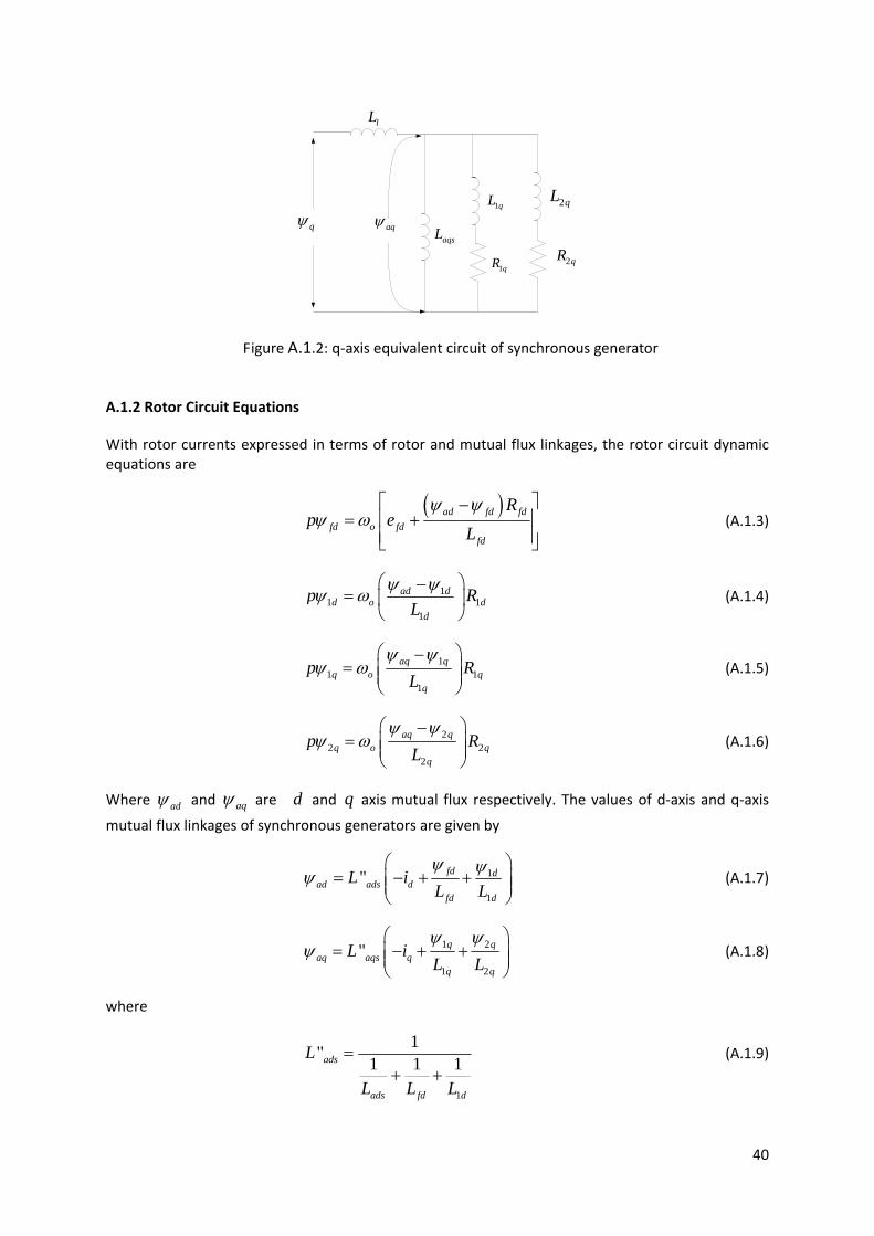
40
lL
2qL
2qRaqsL
1qL
1qR
aqψqψ
Figure A.1.2: q‐axis equivalent circuit of synchronous generator
A.1.2 Rotor Circuit Equations
With rotor currents expressed in terms of rotor and mutual flux linkages, the rotor circuit dynamic equations are
( )ad fd fdfd o fd
fd
Rp e
Lψ ψ
ψ ω⎡ ⎤−⎢ ⎥= +⎢ ⎥⎣ ⎦
(A.1.3)
11 1
1
ad dd o d
d
p RL
ψ ψψ ω⎛ ⎞−
= ⎜ ⎟⎝ ⎠
(A.1.4)
11 1
1
aq qq o q
q
p RL
ψ ψψ ω
⎛ ⎞−= ⎜ ⎟⎜ ⎟
⎝ ⎠
(A.1.5)
22 2
2
aq qq o q
q
p RL
ψ ψψ ω
⎛ ⎞−= ⎜ ⎟⎜ ⎟
⎝ ⎠
(A.1.6)
Where adψ and aqψ are d and q axis mutual flux respectively. The values of d‐axis and q‐axis
mutual flux linkages of synchronous generators are given by
1
1
" fd dad ads d
fd d
L iL Lψ ψψ
⎛ ⎞= − + +⎜ ⎟⎜ ⎟
⎝ ⎠ (A.1.7)
1 2
1 2
" q qaq aqs q
q q
L iL Lψ ψ
ψ⎛ ⎞
= − + +⎜ ⎟⎜ ⎟⎝ ⎠
(A.1.8)
where
1
1" 1 1 1ads
ads fd d
L
L L L
=+ +
(A.1.9)

41
1 2
1" 1 1 1aqs
aqs q q
L
L L L
=+ +
(A.1.10)
Here adsL and aqsL are saturated values of the d ‐axis and q ‐axis mutual inductances given by
ads sd aduL K L= (A.1.11)
aqs sq aquL K L=
(A.1.12)
where sdK and sqK are computed as a function of air gap flux linkage and normally provided in
data sheet of generator.
A.1.3 Stator Voltage Equations
With the stator transients ( dpψ , qpψ ) and speed variations ( / oω ω ) neglected, the stator voltages
may be written as follows.
" "( )d a d q q de R i L i Eω= − + +
(A.1.13)
" "( )q a q d d qe R i L i Eω= − − +
(A.1.14)
where "dE and "
qE are d and q axis back emf’s of the synchronous generator respectively. They
are given by
1 2" "
1 2
q qd aqs
q q
E LL Lψ ψ
ω⎛ ⎞
= − +⎜ ⎟⎜ ⎟⎝ ⎠
(A.1.15)
" " 1
1
fd dq ads
fd d
E LL Lψ ψω⎛ ⎞
= +⎜ ⎟⎜ ⎟⎝ ⎠
(A.1.16)
" "d l adsL L L= + (A.1.17)
" "q l aqsL L L= +
(A.1.18)
Since we neglect the effect of the speed variations on the stator voltage, / 1.0oω ω ω= = in the
above equations. Consequently, " "d dL Xω = and " "
q qL Xω = . All the above equations used for
simulation of the machine are in the individual machine d q− reference frame which rotates with the machine’s rotor. For the solution of interconnecting transmission network equations, a synchronously rotating common R I− frame is used.
The relationships shown in Figure A.1.3 are used to transform variables from one reference frame to the other. The R‐axis of the common reference frame also serves as the reference for measuring the rotor angle δ of each machine.
sin cosd R Ie E Eδ δ= − (A.1.19)

42
sin cosq I Re E Eδ δ= +
(A.1.20)
sin cosR d qE e eδ δ= +
(A.1.21)
sin cosI q dE e eδ δ= −
(A.1.22)
Figure A.1.3: d‐q and R‐I frame transformation
Since we neglect the effect of the speed variations on the stator voltage, / 1.0oω ω ω= = in the
above equations, consequently, " "d dL Xω = and " "
q qL Xω = . For convenience of organization of the
complete set of algebraic equations, the stator voltage equations are expressed in the common R‐I reference. Uses of Equation A.1.21 and Equation A.1.22 to transform the stator voltage Equation A.1.13 and Equation A.1.14 yields
"
"R RR RI R R
I IR II I R
E R X I EE X R I E
⎡ ⎤−⎡ ⎤ ⎡ ⎤ ⎡ ⎤= + ⎢ ⎥⎢ ⎥ ⎢ ⎥ ⎢ ⎥− − ⎢ ⎥⎣ ⎦ ⎣ ⎦ ⎣ ⎦ ⎣ ⎦
(A.1.23)
The elements of impedance matrix are given by
" "( )sin cosRR d q aR X X Rδ δ= − +
(A.1.24)
" "( )sin cosII q d aR X X Rδ δ= − +
(A.1.25)
" 2 " 2cos sinRI d qX X Xδ δ= +
(A.1.26)
" 2 " 2sin cosIR d qX X Xδ δ= +
(A.1.27)
As noted earlier, ω is assumed to be 1.0 pu. The internal voltage components are given by
" " "sin cosR d qE E Eδ δ= +
(A.1.28)
" " "sin cosI q dE E Eδ δ= −
(A.1.29)

43
A.2 Transformer Model
pv sv
pi si
1y
3y2y
Figure A.2: General π network
The π network (derived from figure 4.1) is shown in Figure A.2, where the terminal current at bus p is
(A.2.1)
Where . Similarly, the terminal current at bus s is
(A.2.2)
The corresponding terminal currents for the π network shown in Figure 4.2are
(A.2.3)
(A.2.4)
Equating the corresponding admittance terms in equations (4.1) and (4.3), we have
(A.2.5)
And
(A.2.6)
Where . Similarly, from equations (4.2) and (4.4),
(A.2.7)

44
A.3 Tap Changing Transformer Model
iV jV
taY
tYa)1( −tYaa )1( −
i j
Figure A.3: Equivalent scheme of Load tap changing transformer
In this report the load tap changing transformer (LTC) is modelled as a π equivalent circuit with elements that depend on the tap ratio. In Fig. A.3, the LTC connected between nodes i and j has the variable tap ratio a and the longitudinal admittance tY . The admittance of the magnetizing branch
has been neglected. The tap ratio is determined to maintain the voltage at the controlled bus (for example, node j in Fig. C.1 to a desired value, refV . When the voltage magnitude, tV , at the
controlled bus is outside the range defined by the adjustable dead band of the regulator, control action is taken to bring the voltage tV back to the desired value refV . The control action consists of
changing the tap ratio of the transformer by changing the tap position. The tap position is moved in a finite number of steps. In mathematical problems involving power flow calculations or quasi‐steady‐state, the difference between two tap positions is assumed small so that the tap ratio of the transformer can be modelled as a continuous function, i.e.
(A.3.1)
Where T > 0 is the time constant of the controller. According to Eq (A.3.1), when the voltage tV
tends to decrease, the tap ratio, a, will take a higher value such that tV is brought back to the
desired value refV . When using a continuous model, the dead band of the transformer is often
ignored. Once a final solution has been found, a rounding or discretization algorithm is applied to converse the value of a to a discrete setting.

45
A.4 Transmission Line Model
Figure A.4: Equivalent π circuit of transmission line
The transmission line of length has been modelled as nominal π equivalent circuit with an approximation of where = propagation constant with
Shunt admittance per unit length/ phase and
=Series impedance per unit length/phase
From [19], the expression of the lumped parameters become: (A.4.1)
(A.4.2)
Here Z and Y represent the total series impedance and the total shunt admittance respectively.
Generally the approximation is good if km for overhead lines and km for underground cables.
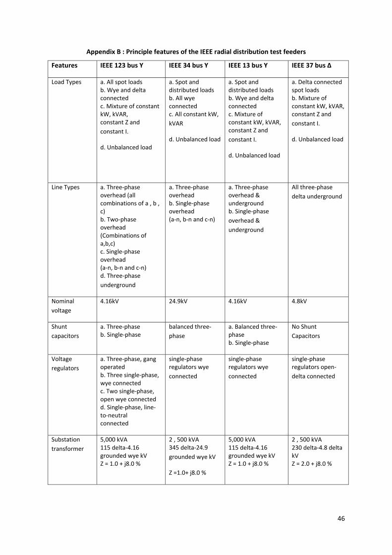
46
Appendix B : Principle features of the IEEE radial distribution test feeders
Features IEEE 123 bus Y IEEE 34 bus Y IEEE 13 bus Y IEEE 37 bus Δ
Load Types a. All spot loads b. Wye and delta connected c. Mixture of constant kW, kVAR, constant Z and constant I.
d. Unbalanced load
a. Spot and distributed loads b. All wye connected c. All constant kW, kVAR
d. Unbalanced load
a. Spot and distributed loads b. Wye and delta connected c. Mixture of constant kW, kVAR, constant Z and constant I.
d. Unbalanced load
a. Delta connected spot loads b. Mixture of constant kW, kVAR, constant Z and constant I.
d. Unbalanced load
Line Types a. Three‐phase overhead (all combinations of a , b , c) b. Two‐phase overhead (Combinations of a,b,c) c. Single‐phase overhead (a‐n, b‐n and c‐n) d. Three‐phase underground
a. Three‐phase overhead b. Single‐phase overhead (a‐n, b‐n and c‐n)
a. Three‐phase overhead & underground b. Single‐phase overhead & underground
All three‐phase delta underground
Nominal voltage
4.16kV 24.9kV 4.16kV 4.8kV
Shunt capacitors
a. Three‐phase b. Single‐phase
balanced three‐phase
a. Balanced three‐phase b. Single‐phase
No Shunt Capacitors
Voltage regulators
a. Three‐phase, gang operated b. Three single‐phase, wye connected c. Two single‐phase, open wye connected d. Single‐phase, line‐to‐neutral connected
single‐phase regulators wye connected
single‐phaseregulators wye connected
single‐phaseregulators open‐delta connected
Substation transformer
5,000 kVA 115 delta‐4.16 grounded wye kV Z = 1.0 + j8.0 %
2 , 500 kVA345 delta‐24.9 grounded wye kV
Z =1.0+ j8.0 %
5,000 kVA115 delta‐4.16 grounded wye kV Z = 1.0 + j8.0 %
2 , 500 kVA 230 delta‐4.8 delta kV Z = 2.0 + j8.0 %

47
Appendix C Literature review
INTELLIGENT GRID‐Literature Review Page i
CSIRO Intelligent Grid Cluster: Project-1
Literature or Technical Review
July 2009
Authors Tapan Kumar Saha,
Tareq Aziz & Sudarshan Dahal, Zhao Yang Dong,

INTELLIGENT GRID‐Literature Review Page ii
Disclaimer
Acknowledgements
Citation

INTELLIGENT GRID‐Literature Review Page iii
No table of figures entries found.

INTELLIGENT GRID‐Literature Review Page iv
Executive Summary
This report presents the background of the project in the context of large scale penetration of distributed generation in sub-transmission and distribution level networks. This report provides literature review of the proposed research on Control methodologies of Distributed Generation for enhanced network stability and control. The report was originally prepared by A/Prof Zhao Yang Dong. During the last couple of months two PhD students (Tareq Aziz with the project scholarship and Sudarshan Dahal with a UQ postgraduate research scholarship) have joined the group. Prof Saha along with the two PHD students has updated the report in the framework of two PhD students’ research topics, which are derived from the original project proposal.
In this report importance of different types DG modelling, stability assessment techniques and design of new control methods has been identified as key tasks. In this report, the key aspects of the research scope, current literatures on the topic and overview of future research plans are presented. In summary, the project addresses the following topics:
• Power system elements and different types of DG modelling
• System stability assessment techniques
• DG and system control methodology development
Appendices
INTELLIGENT GRID‐Literature Review Page v
Abbreviations

INTELLIGENT GRID‐Literature Review Page vi
Key Words
Distributed generation, Doubly Fed Induction Generator (DFIG), control methodologies, power system stability, voltage stability, small signal stability FACTS devices, SVC, STATCOMS

INTELLIGENT GRID‐Literature Review Page 7
Introduction
a. Project background
This project is supported by CSIRO under its flagship funding scheme. The original research proposal serves as the background for this project and is copied below for completeness:
P1: Control methodologies of Distributed Generation for enhanced network stability and control – (UQ)
Investigators: Zhao Dong, Tapan Saha
The project proposed here addresses the key issues related to the integration of Distributed Generation centrally controlled in the National Electricity Market (NEM). Currently 80% of the energy consumed in Australia comes from coal-based power stations. The power generation by this traditional fuel had resulted in one of the highest per capita greenhouse gas emissions in the world.
The August 2003 blackout in North America and subsequent major blackouts in Italy and in Scandinavian countries had highlighted the needs to improve the security of the power system. Following the deregulation of the power industry from the 90’s, many power systems have been stressed towards their maximum power transfer limits. Many of these blackouts are, either directly, or indirectly related to the constrained transmission system.
It is expected that increasing amounts of new technologies in the form of distributed generations will be introduced in electrical power systems in the coming years. The emphasis on power generation from renewable sources leads to the development and the use of technologies, such as solar panels, wind turbines and wave energy power plants. Introduction of DG has the following opportunities:
• DG units can be connected closer to customers and hence transmission and distribution costs can be significantly reduced.
• The latest technology has made available plants with high efficiency and ranging in capacity from l0kW to 15MW, in particular wind farms.
• The liberalization of the electricity market contributes to creating opportunities for new utilities in the power generation sector;
Many of these new technologies do not use a conventional grid coupled synchronous generator to convert primary energy into electricity. Instead, they either use a squirrel cage or doubly fed induction generator (in particular for wind turbine). A further difference between these new technologies and conventional means of electrical power generation is that many of them are of considerably smaller in size than conventional thermal, nuclear, and hydro units and their sources of primary energy are volatile. Therefore, they are often connected to low and medium voltage grids and not to the high voltage transmission grid. As long as the penetration level of these new technologies in power systems is still low and they only cover a small fraction of the system load, they have little impact on the dynamic behaviour of a power system. Therefore, in power system long-term dynamics and transient stability studies, they are normally considered as negative load and their intrinsic dynamics are not taken into account. However, if the amount of new generation technology introduced in a power system

INTELLIGENT GRID‐Literature Review Page 8
becomes substantial, it will significantly influence the overall behaviour of the system. Penetration level (MW and voltage), location and proper model of the distributed generation will be important factors in the analysis of dynamic behaviour of power system. The goal of the research would be to investigate the impacts of distributed generation on power system transient, small signal, and long term stability.
The outcome of the research would be to provide:
• Comprehensive model of DG system for power system stability analyses. • A software platform for testing and evaluating new DG technologies from the system security
point of view. • Proper control design to integrate DG with existing large power grid without violating system
constraints. • A comprehensive understanding of the security issues of integration of distributed generation
in the National Electricity Market (NEM) Grid
Output/deliverables:
Publications in international conferences and journals
Training of PhD students through out the project
Half yearly report on the project main milestone of achievements
A package of algorithms and software for testing, evaluating and integrating DG in the NEM grid

INTELLIGENT GRID‐Literature Review Page 9
Insert section e.g. macro level study overview
Distributed generation as the primary form for enabling renewable energy supply has been emerging as the new direction for power engineering research. A number of issues drive the increasing development in DGs, including
Kyoto Protocol driven emissions trading scheme
Sustainable energy supply needs
Global warming concerns
New enabling technologies, such as micro turbine and hybrid electric vehicles
Economic power system operation and planning needs
Furthermore, government policies are increasingly encouraging utilisation of renewable energy resources, which mainly relay on distributed generation.
In this study, a number of issues will be studied in the macro level for distributed generation and its applications, these include
Study the state-of-the art of DGs and its control methodologies
Modelling of Distributed Generation Modules
Modelling of power system incorporating DGs
Control methodologies for DGs to ensure power system stability
Some relevant project work has been completed in the recent past and more in progress in this area of research within the power and energy systems research group at the University of Queensland. A number of publications have appeared/accepted for publication in Transactions, book chapters, and referred conferences. Some related papers from the group are listed below:-

INTELLIGENT GRID‐Literature Review Page 10
[1] Y. Mishra, S. Mishra and ZY Dong, “Improving Stability of a DFIG based wind power system with tuned damping controller”, accepted (Oct 2008) to appear in IEEE Trans on Energy Conversion
[2] SHI Libao; XU Zheng; and Z. Y. Dong, “Wind Turbine Model and Initialization Analysis with High Penetration of Grid-connected Wind Farms of DFIG Type”, Hydropower Automation and Dam Monitoring. 2008, 32(3). pp 44-48.
[3] Vinod Kumar, Steven Kong, Yateendra Mishra, Z. Y. Dong, and Ramesh C. Bansal, Doubly Fed Induction Generators: overview and control strategies for a wind energy conversion systems, Chapter in Intelligent Information Systems and Knowledge Management for Energy: Applications for Decision Support, Usage and Environmental Protection, Kostas Metaxiotis, ed. NTUA
[4] Y. Mishra, R. Majumder and ZY Dong, “Design of fixed order robust power oscillation damper for TCSC”, IEEE PES General Meeting 2008, Pittsburgh, USA
[5] Q. Liu, Y. Xue, ZY Dong, G. Ledwich and Y. Yuan, “Abnormal Effects of Line Fault Location on Transient Stability and its Mechanism”, Automation of Electric Power Systems, 31(18), 2007
[6] Y. Mishra, Z.Y. Dong, J. Ma and D.J. Hill, “Induction Motor Load Impact on Power System Eigenvalue Sensitivity Analysis”, accepted to appear (Aug 08) IET Generation Transmission and Distribution
[7] Y. Mishra, S. Mishra and ZY Dong, “Rough Fuzzy Control of SVC for Power System Stability Enhancement”, accepted to appear in Int Journal of Electrical Engineering and Technology (2008)
[8] G.Y. Yang, Y. Mishra, ZY Dong and KP Wong, “Optimal Power System Stabilizer Tuning in Multi-machine System via an Improved Differential Evolution”, Proc. IFAC 2008. (invited regular paper)
[9] G. Yang, G. Hovland, R. Majumder and ZY Dong, “TCSCs Allocation Based on Line Flow Equations Via Mixed-Integer Programming”, IEEE Trans on Power Systems, Vol 22, No. 4, Nov 2007, pp. 2262-2269.

INTELLIGENT GRID‐Literature Review Page 11
Insert section e.g. micro level study overview
The study of DG control methodologies will include the following micro level studies.
I. System modelling
In this part, modelling methodologies of DG systems including different types of generation resources and their prime movers will be studied to derive appropriate models for later simulation and analysis purpose. The power system incorporating the DG units will also be modelled at sub- transmissions and distribution levels to reflect the characteristics of DGs.
It is essential to model these DG units in a power system at appropriate level for stability assessment and simulation needs. Their dynamics contribute to the overall system dynamics of a power system. By considering the DG impact, the complexity of power system stability and control analysis increases accordingly. System modelling will also include load dynamics in addition to DG units and the conventional generation, transmission, and distribution systems of a power system. It is well recognised that load dynamics play an important role in determining power system dynamic as well as steady state stability properties. In the most simple and straight forward form of system stability analysis – steady state voltage stability, which normally rely on QV and PV curves, load characteristics may dramatically change the point of collapse or the steady state stability limit of a power system.
II. System stability assessment
Stability analysis of a power system incorporating DG units is a key part of this project. DGs bring uncertainties from the generation side to the power system, and therefore require more advanced methodologies for system stability assessment.
The primary responsibilities of a system operator, such as NEMMCO in the Australian National Electricity Market, is to ensure system security, which requires the system operate in a stable mode when subjected to creditable system contingencies. Although at current stage, the overall impact from DGs in the Australian NEM grid is still small in stability assessment, however, with the increasing penetration of DGs into the NEM grid, it has been identified by the IRPC (Inter Regional Planning Council) that their impact should be considered in system stability and planning studies by the transmission network service providers (TNSP’s) in the Australian NEM.
System stability starting from the basic steady state (voltage) stability, to oscillatory stability and transient stability will be studied in this research project. Mathematical models describing the power system steady state as well as dynamic properties including DG’s and load dynamics will be developed for this project. These models will be developed in MatLab, and where appropriate in engineering specialty software such as PSS/E and PSCAD/EMTDC and DIgSILENT Power Factory.
III. System control methodologies
Control of a power system incorporating DG units requires detailed system modelling and thorough understanding of the complex system dynamics. With the modelling and stability work in the previous phases of this project, such knowledge should be developed and ready to be used for new advanced controller development. In addition to the control mechanism of the DG units themselves, system wide control methods aiming at overall system stability are needed. This requires advanced control

INTELLIGENT GRID‐Literature Review Page 12
techniques as well as system facilities such as use of flexible AC transmission systems (FACTS) – especially SVC’s and STATCOM’s, and system measurement devices to enable wide area measurement based approach.

INTELLIGENT GRID‐Literature Review Page 13
Detailed Literature Review
Literature review on modelling of DGs
Distributed Generation (DG) is defined as the production of electricity in a decentralized facility. Because of numerous advantages, it is expected to play an increasing role in the electric power system in the near future. A tentative classification of DG units has been shown in [1]. With time, these technologies are entering into the power system with rapid expansion and commercialization. The introduction of distributed generation units on the existing power system can significantly impact the flow of power and voltage conditions at customers and utility equipment. These impacts may imply themselves either positively or negatively depending on the characteristics of both the distribution system and the DG units [2]. To study the impact of DG when integrated into a typical distribution system, computer models are needed to be developed that include DG’s of different technologies. Along with the unit itself, control systems are also simulated and implemented. Models should depict behaviour of DG under different fault conditions and the resulting voltage and power flow in the whole system due to the presence of DG’s [3]. Till to date, many analysis has been performed on power flow with the presence of Distributed Generation units. In general, in most of these studies, the DG units have been modelled as PV or PQ nodes for power flow calculations without explaining proper reasons [4-8]. Different authors have used various mathematical relations to model asynchronous DGs, synchronous DGs and DG units which are connected to the distribution system [9-11]. In a recent paper [12], a helpful list of DG models was presented considering the machine operation and the type of interface/connection to the grid for power flow analysis. Among all the DG resources, Wind energy has emerged as the most dynamically growing renewable source for the last few years. For example, in Germany a total Wind Turbine (WT) capacity of 50GW is expected by 2020, which is more than 50% of the German peak load [13, 14]. Our project is more directed to large and medium size DG units [15], wind turbines become one of our critical choice to study in details. To study the impact of large penetration of Wind turbines & wind farms in power system, proper and well defined WT models are required. These models should ensure proper presentations for dynamic interactions between the grid and WTs for the simulation of power system. Different publications over the years tackle different aspects of WTs [16-24] for modelling. Among all these work, most of the literature has been found to deal with Doubly Fed Induction Generator (DFIG), as the preferred technology because of reduced mechanical load and increased possibility of power control. Wind turbines in most cases is presented by a generic model with 6 interconnected block elements – aerodynamic system, mechanical system, generator drive, pitch control system, wind turbine control system and protection system [25]. So far, the most detailed level model for WT that exists is called 6th order state variable model, which includes both rotor and stator electromagnetic transients. This model has been treated as an appropriate model for studies on instantaneous value modelling of the power system. But it limits the size of the system that can be simulated. A small step is required for numerical integration resulting in greater computational time [26]. For these, it has become
INTELLIGENT GRID‐Literature Review Page 14
conventional to reduce the order of the wind generator model and neglect the network transients. But with the reduction of order, although computational advantage is achieved, the details of the system behaviour are lost. For example, the 3rd order model is adequate for dynamic modelling only, but it does not offer good resolution for fault current contribution. The 5th order model provides better details in that regard. However, the DFIG model still does not include any magnetic saturation, air gap harmonics or skin effects. So the WT model still needs some adaptations and details for standardization. The end of year report in July 2009 will include the other types of DG models, which will be studied in details in this project. References: [1] W. El-Khattam, M.M.A. Salama, “Distributed generation technologies, definitions and
benefits”, Electric Power Systems Research 71 (2004) pp 119–128. [2] Philip P. Barker, Robert W. de Mello, “Determining the Impact of Distributed Generation on
Power Systems: Part 1 - Radial Distribution Systems”, Presented at IEEE [3] Kojovic, L, “Modeling of DG to interface with distribution system”, presented at
IEEE Power Engineering Society Summer Meeting, 2002, Volume 1, 25-25 July 2002, Page(s):179 - 180 vol.1
[4] G.X. Luo, A. Semlyen, “Efficient load flow for large weakly meshed networks”, IEEE Trans. Power Syst. 5 (4), (1990) 1309–1316.
[5] C.S. Cheng, D. Shirmohammadi, “A three-phase power flow method for real-time Distribution system analysis”, IEEE Trans. Power Systems, 10 (2) (1995) 671–679
[6] S. Khushalani, N. Schulz, “Unbalanced distribution power flow with distributed Generation”, in: IEEE Transm. Distrib. Conf., 2006, pp. 301–306.
[7] S. Khushalani, J.M. Solanki, N.N. Schulz, “Development of three-phase unbalanced power flow using PV and PQ models for distributed generation and study of the impact of DG models”, IEEE Trans. Power Syst. 22 (3) (2007) 1019–1025. [8] Y. Zhu, K. Tomasovic, “Adaptive power flow method for distribution systems with
Dispersed generation”, IEEE Trans. Power Delivery, 17 (3) (2002) 822–827. [9] A. Losi, M. Russo, “Dispersed generation modeling for object-oriented distribution
load flow”, IEEE Trans. Power Delivery, 20 (2) (2005) 1532–1540. [10] H. Chen, J. Chen, D. Shi, X. Duan, Power flow study and voltage stability analysis for distribution systems with distributed generation, in: IEEE Power Engineering
Society General Meeting, 18–22 June, 2006. [11] K.C. Divya, P.S. Nagendra Rao, “Models for wind turbine generating systems and their
application in load flow studies”, Electric Power Syst. Res. 76 (2006) 844–856. [12] S.M. Moghaddas-Tafreshi, Elahe Mashhour, “Distributed generation modeling for power
flow studies and a three-phase unbalanced power flow solution for radial distribution systems considering distributed generation”, Electric Power Systems Research 79 (2009) 680–686
[13] I. Erlich and U. Bachmann, “Grid code requirements concerning connection and operation of wind turbines in Germany,” in Proc. IEEE Power Eng. Soc. General Meeting, Jun. 12–16, 2005, pp. 2230–2234.
[14] I. Erlich, W.Winter, and A. Dittrich, “Advanced grid requirements for the integration of wind turbines into the German transmission system,” presented at the IEEE Power Eng. Soc. General Meeting, Montreal, QC, Canada, 2006, panel paper 06GM0837.
[15] T. Ackerman, G Anderson, and L Soder, “Distributed generation: a definition”, Electric Power Systems Research (57), 195-204, 2001.
INTELLIGENT GRID‐Literature Review Page 15
[16] M. A. Pöller, “Doubly-fed induction machine models for stability assessment of wind farms,” presented at the Proc. IEEE PowerTech, Bologna, Italy, Jun. 2003, BPT0-345.
[17] F. M. Hughes, O. Anaya-Lara, N. Jenkins, and G. Strbac, “Control of DFIG-based wind generation for power network support,” IEEE Trans. Power Syst., vol. 20, no. 4, pp. 1958–1966, Nov. 2005.
[18] L. Holdsworth, X. G. Wu, J. B. Ekanayake, and N. Jenkins, “Direct solution method for initializing doubly-fed induction wind turbines in power system dynamic models,” Proc. Inst. Elect. Eng., Gen., Transmission Distribution., vol. 150, no. 3, pp. 334–342, May 2003.
[19] J. B. Ekanayake, L. Holdsworth, X. G. Wu, and N. Jenkins, “Dynamic modelling of doubly fed induction generator wind turbines,” IEEE Trans. Power Syst., vol. 18, no. 2, pp. 803–809, May 2003.
[20] Y. Lei, A. Mullane, G. Lightbody, and R. Yacamini, “Modeling of the wind turbine with a doubly fed induction generator for grid integration studies,” IEEE Trans. Energy Convers., vol. 21, no. 1, pp. 257–264, Mar. 2006.
[21] A. Mullane and M. O’Malley, “The inertial response of induction-machine- based wind turbines,” IEEE Trans. Power Syst., vol. 20, no. 3,pp. 1496–1503, Aug. 2005.
[22] D. Xiang, L. Ran, P. J. Tavner, and S. Yang, “Control of a doubly fed induction generator in a wind turbine during grid fault ride-through,” IEEE Trans. Energy Conversion, vol. 21, no. 3, pp. 652–662, Sep. 2006.
[23] Y. Lei, A. Mullane, G. Lightbody, and R. Yacamini, “Modeling of the wind turbine with a doubly fed induction generator for grid integration studies,” IEEE Trans. Energy Convers., vol. 21, no. 1, pp. 257–264,Mar. 2006.
[24] P. Ledesma and J. Usaola, “Doubly fed induction generator model for transient stability analysis”, IEEE Trans. Energy Conversion, vol. 20, no. 2, pp. 388–397, Jun. 2005.ion
[25] Thomas Ackermann, Wind power in power systems, John Wiley and Sons’ Ltd, 2005. [26] L. H. J.B. Ekanayake, and N. Jenkins, "Comparison of 5th order and 3rd order machine
models for doubly fed induction generator (DFIG) wind turbines," Electric Power Systems Research, vol. 67, pp. 207-215, Dec. 2003.
Modelling of Important Elements of Distributed Generations
Whether distributed generation are connected with the distribution system or constructed as large offshore wind-farm generating system, they have great influence on every aspects of power system. Proper component modelling is, therefore, necessary for accurate results of the impact analysis. The issues of modelling and analysis of distributed generations, which are found in the review of various literatures, are summarized below.
1. Load Modelling: Most of the literatures dealing with DGs have assumed loads as constant in their analyses. Since the loads are voltage and frequency sensitive, analysis assuming constant loads will give inaccurate and misleading results. Since the integration of DG units has been known as an alternative for main grid as a resource for energy supply, the determination of optimal sizing and sitting is an important issue in the planning procedure of DG. It is shown that load models can significantly affect the optimal location and sizing of distributed generation (DG) resources in distribution systems.
2. Distribution System Planning: Distributed generation (DG) has impacts on the performance of connected sub-transmission and distribution network. The increase of fault currents in

INTELLIGENT GRID‐Literature Review Page 16
power systems is a consequence of the appearance of new generation sources. DG is usually not requested to participate in voltage regulation of the distribution network and will be disconnected from the distribution network quickly enough when a fault occurs in it for eliminating DG's negative influence. But in this way it will also limit the capability of DG to suppress the voltage sag of distribution network in faulty condition. Some operating and planning limitations may be imposed by the resulting fault currents.
3. Load Sharing: Under heavy load, the power system can become unstable exhibiting voltage drops that may lead to a voltage collapse. When wind generation and micro-turbines units are installed in a distribution system, they may cause reverse power flows and voltage variations due to the random-like outputs of the turbines.
4. Load Flow Analysis: With the increased installations of distributed generators (DGs) within power systems, load flow analysis of distribution systems needs special models and algorithms to handle multiple sources. The connection of small generating units affects the operation of distribution systems and classical modelling and analysing techniques must be revised. Recently, a novel approach to the distribution load-flow problem has been proposed: the object-oriented (OO) paradigm has been applied both to the system modelling and to the Newton-Raphson solving algorithm in the cases of radial and weakly meshed distribution systems.
5. Modelling of Generators: The mathematical models of distributed generations (DGs) are integrated into three-phase distribution load flow program to analyse and simulate the penetrations of DGs for distribution systems. DGs can utilise the traditional energy sources such as oil and coal or renewable energy sources such as wind, solar and fuel cell and use rotating generators or converters to transfer energy to power grids. According to the characteristics of output power, DGs can be specified as constant power factor model, constant voltage model or variable reactive power model in the load flow analysis.
6. System Modelling Approach: A Subtransmission or distribution network, where DGs are connected to the grid, cannot be considered as passive anymore. Therefore, in the future it will not be possible to use simple equivalents of distribution networks for power system dynamic modelling, as it was done before. At the same time, the whole power system cannot generally be represented in a detailed manner for dynamic studies because of huge system dimension.
Although there are many literatures on modelling of distributed generations, the generalized mathematical modelling of the distributed resources has hardly been achieved. The intermittent nature of the power generation and unbalancing of the distribution system has added complexity of system analysis. Moreover, the system modelling depends of the local configuration of the distributed resources. As the penetration level of these resources is high, the system has its unique dynamic characteristics. The modelling of the DGs also depends on the manufacturer design of the components used. As there are a number of DGs working parallel, an equivalent aggregate model of the DGs is necessary to simplify the system analysis.
References
1. Hatziadoniu, C.J.; Lobo, A.A.; Pourboghrat, F.; Daneshdoost, M., "A simplified dynamic model of grid-connected fuel-cell generators ," Power Delivery, IEEE Transactions on , vol.17, no.2, pp.467-473, Apr 2002

INTELLIGENT GRID‐Literature Review Page 17
2. Kroutikova, N.; Hernandez-Aramburo, C.A.; Green, T.C., "State-space model of grid-connected inverters under current control mode," Electric Power Applications, IET , vol.1, no.3, pp.329-338, May 2007
3. Guttromson, R.T., "Modeling distributed energy resource dynamics on the transmission system," Power Systems, IEEE Transactions on , vol.17, no.4, pp. 1148-1153, Nov 2002
4. Wang Jili; He Renmu; Ma Jin, "Load Modeling Considering Distributed Generation," Power Tech, 2007 IEEE Lausanne , vol., no., pp.1072-1077, 1-5 July 2007
5. Sedghisigarchi, K.; Feliachi, A., "Dynamic and transient analysis of power distribution systems with fuel Cells-part I: fuel-cell dynamic model," Energy conversion, ieee transactions on , vol.19, no.2, pp. 423-428, June 2004
6. Sedghisigarchi, K.; Feliachi, A., "Dynamic and transient analysis of power distribution systems with fuel Cells-part II: control and stability enhancement," Energy conversion, ieee transactions on , vol.19, no.2, pp. 429-434, June 2004
7. Grilo, A.P.; Mota, A.d.A.; Mota, L.T.M.; Freitas, W., "An Analytical Method for Analysis of Large-Disturbance Stability of Induction Generators," Power Systems, IEEE Transactions on , vol.22, no.4, pp.1861-1869, Nov. 2007
8. Soultanis, N. L.; Papathanasiou, S. A.; Hatziargyriou, N. D., "A Stability Algorithm for the Dynamic Analysis of Inverter Dominated Unbalanced LV Microgrids," Power Systems, IEEE Transactions on , vol.22, no.1, pp.294-304, Feb. 2007
9. Singh, D.; Misra, R.K., "Effect of Load Models in Distributed Generation Planning," Power Systems, IEEE Transactions on , vol.22, no.4, pp.2204-2212, Nov. 2007
10. Marwali, M.N.; Jin-Woo Jung; Keyhani, A., "Stability Analysis of Load Sharing Control for Distributed Generation Systems," Energy conversion, ieee transactions on , vol.22, no.3, pp.737-745, Sept. 2007
11. Spetlik, J.; Tlusty, J., "Analysis of distributed generation sources using abc synchronous machine model," Future Power Systems, 2005 International Conference on , vol., no., pp.6 pp.-6, 18-18 Nov. 2005
12. Lin Chen; Jin Zhong; Deqiang Gan, "Reactive power planning and its cost allocation for distribution systems with distributed generation," Power Engineering Society General Meeting, 2006. IEEE , vol., no., pp.6 pp.-, 0-0 0
13. Khushalani, S.; Solanki, J.M.; Schulz, N.N., "Development of Three-Phase Unbalanced Power Flow Using PV and PQ Models for Distributed Generation and Study of the Impact of DG Models," Power Systems, IEEE Transactions on , vol.22, no.3, pp.1019-1025, Aug. 2007
14. Chindris, M.; Sudria i Anderu, A.; Bud, C.; Tomoiaga, B., "The load flow calculation in unbalanced radial electric networks with distributed generation," Electrical Power Quality and Utilisation, 2007. EPQU 2007. 9th International Conference on , vol., no., pp.1-5, 9-11 Oct. 2007
15. Teng, J.-H., "Modelling distributed generations in three-phase distribution load flow," Generation, Transmission & Distribution, IET , vol.2, no.3, pp.330-340, May 2008
16. Syafii; Nor, K.M.; Abdel-Akher, M., "Analysis of three phase distribution networks with distributed generation," Power and Energy Conference, 2008. PECon 2008. IEEE 2nd International , vol., no., pp.1563-1568, 1-3 Dec. 2008
17. Haffner, S.; Pereira, L.F.A.; Pereira, L.A.; Barreto, L.S., "Multistage Model for Distribution Expansion Planning With Distributed Generation—Part I: Problem Formulation," Power Delivery, IEEE Transactions on , vol.23, no.2, pp.915-923, April 2008

INTELLIGENT GRID‐Literature Review Page 18
18. Haffner, S.; Pereira, L.F.A.; Pereira, L.A.; Barreto, L.S., "Multistage Model for Distribution Expansion Planning with Distributed Generation—Part II: Numerical Results," Power Delivery, IEEE Transactions on , vol.23, no.2, pp.924-929, April 2008
19. D'Albertanson, B.; Hawkins, D., "An integrated MV distributed generation connection planning tool," SmartGrids for Distribution, 2008. IET-CIRED. CIRED Seminar , vol., no., pp.1-4, 23-24 June 2008
20. Reddy, G. Sridhar; Singh, R. K., "Modeling and control of a distributed generation system," Information and Communication Technology in Electrical Sciences (ICTES 2007), 2007. ICTES. IET-UK International Conference on , vol., no., pp.256-261, 20-22 Dec. 2007
21. Ramesh, L.; Chowdhury, S.P.; Chowdhury, S.; Song, Y.H.; Natarajan, A.A., "Voltage stability analysis and real power loss reduction in distributed distribution system," Transmission and Distribution Conference and Exposition, 2008. T&D. IEEE/PES , vol., no., pp.1-6, 21-24 April 2008
Modelling of Wind Turbine Generators for Wind Power
The conventional power plants are based on fixed speed rotor concept and employ synchronous generators for power generation. The alternative energy resources such as wind power are intermittent type of the resources which makes the use of synchronous generators not feasible for power generation. Recent progress in the development of controlled static-var sources makes it possible to consider induction generators coupled with controlled VAr sources as a technically feasible alternative to the use of synchronous machines [1]. With the flexibility of variable speed operation, induction generators are preferred in wind power generations. The types of induction generators used and the modelling approaches taken are briefly summarised below. Wind Turbine Generators
The major part of wind turbine concepts today is based on induction generator concept [2]. The first wind turbines of induction generator based concepts have been fixed-speed and equipped with conventional induction generators with a short circuited rotor circuit. The presence of an electromechanical slip that is the relative difference between the electrical speed of power grid and mechanical speed of generator rotor, provides a relatively flexible coupling between fluctuating power of rotor (with fluctuating rotor speed) and the electrical power grid (with a fixed frequency). This is termed as fixed speed concept because the speed in normal operation may only vary within a narrow range that is normally up to 2%. While most conventional wind farms were based on fixed speed induction generators (FSIG), more recent instalments tend to use the doubly-fed induction generator (DFIG). Figure 1 and Figure 2 show the schematic diagram of FSIG and DFIG.

INTELLIGENT GRID‐Literature Review Page 19
Fig 1. Fixed Speed Induction Generator
Fig 2. Doubly Fed Induction Generator
Models of Doubly Fed Induction Generators (DFIG)
It is now recognized that many large wind farms will employ doubly fed induction generator (DFIG) variable speed wind turbines [4] [5]. A number of such wind farms are already in operation and more are planned or under construction. With the rising penetration of wind power into electricity networks, increasingly comprehensive studies are required to identify the interaction between the wind farm(s) and the power system. These require accurate models of doubly fed induction generator wind turbines and their associated control and protection circuits.
A) Full Model and Reduced Order Models Various models of DFIG are available. The available DFIG models and investigations/demonstrations of the influence of various model parameters and simplifications (for both mechanical and electrical subsystems) on DFIG-based wind plant transient responses are well presented in the literature [6]. A number of the literatures use the models where the stator transients in induction generators are neglected. In [7], it has been shown that neglecting effects of stator transients has negligible effect in the result of the simulation studies. The various models can be categorized as follows based on the coordinate system chosen.
a) Models in synchronously rotating d-q variables: A wind-turbine driven induction generator modelling is also well presented in literatures. The models are mostly developed in a synchronously rotating reference frame [8]. The full model has all the transients associated with induction generator variables considered. The lower order models can be derived by neglecting the fast transients [7, 9]. Singular perturbation theory can also be applied to derive

INTELLIGENT GRID‐Literature Review Page 20
the lower order models [10]. The voltage and frequency control strategy of the generator is developed using the available models of the generator.
b) Models in stationary d-q variables: A generalised dynamic model of a three-phase induction generator can also be developed using d-q variables in a stationary reference frame [11]. This model can handle well symmetrical and unsymmetrical load and capacitor configurations.
c) Models in d-q variables in rotor reference frame: A synchronous machine like modelling of induction machine is a better approach for transient analysis [12]. This model is mostly preferred in the speed control design of induction machines [6].
d) A hybrid d-q model: A steady state analysis of the static Kramer variable speed double output induction generator is conducted using a hybrid d-q model wherein stator variables only are transformed onto a reference frame fixed to the rotor [13]. Rotor variables are retained in their natural abc form. It is useful in predicting the steady state performance of the system operating as a generator when driven above synchronous speed.
B) Brushless Doubly Fed Induction Generator Model The development of the brushless doubly-fed induction generator (BDFIG) system and flexible power flow controller for the wind energy conversion is proposed in [14]. The system employs two cascaded induction machines to eliminate the brushes and copper rings in the traditional DFIG. The dynamic model of BDFIG with two machines' rotor electromechanically interconnected is presented and the control strategy for flexible power flow control is developed. The independent control of the active and reactive power flows is achieved by means of a four quadrant power converter under the closed-loop stator flux oriented control scheme. As this machine does not have brushes, it is considered as maintenance free. However, it shows that harmonic distortion could be reduced but the cost of the system was significantly increased and the system efficiency dropped.
Fig 3. Brushless Doubly Fed Induction Generator Model
C) Linear Dynamic Model
A specific linear dynamic model for an asynchronous machine is presented in [15] [16]. This model is based on the balanced dynamic model of the asynchronous machine and it is developed for asynchronous wind turbines when the mechanical power (wind power) has sinusoidal fluctuations.
D) Algebraic Model for Transient Stability Analysis A simple DFIG model suitable for transient stability has been proposed in [17]. The main assumption adopted in the model is that the current control loops, which are much faster than the electromechanical transients under study, do not have a significant influence on the transient stability of the power system and may be considered instantaneous. The proposed DFIG model is a set of algebraic equations which are solved using an iterative procedure. A method is also proposed to

INTELLIGENT GRID‐Literature Review Page 21
calculate the DFIG initial conditions. A detailed variable-speed windmill model has been developed using the proposed DFIG model.
E) Simple Induction Machine Models A new composite third-order model was developed for wind farms of large wind turbines [18]. This simple model represents the induction generators, local power-factor-correction capacitors and network of a wind farm. This allows the variations in network voltage due to the changing aerodynamic torque of each turbine to be determined conveniently. It has a small computation time as large integration steps may be used and only a few equations need to be solved. It represents accurately the effects of large torque and voltage changes and therefore it would appear suitable for all cases of running wind turbines.
F) Aggregate Model for Simulating Wind Farms A wind farm has a number of wind turbines generator systems. It is convenient to implement an aggregate model into a power system stability program [19]. Various literatures describe the construction of an aggregate model for a cluster of identical, horizontal-axis wind turbines with induction generators. In a transient stability program, this aggregate model is capable of simulating the effects of wind turbulence, tower shadow, and external network disturbances such as faults and line switching.
References 1. de Mello, F.P.F., J.W.; Hannett, L.N.; White, J.C., "Application of Induction Generators in Power Systems," power apparatus and systems, IEEE Transactions on , vol. PAS-101, no.9, pp.3385-3393, Sept. 1982. 2. Thomas Ackermann, "Wind Power in Power Systems", Wiley. 3. Foster S., X.L., and Fox B.,” Coordinated control and operation of DFIG and FSIG based Wind Farms”, PowerTech 2007. 4. S. Muller, M.D., and R.W. De Doncker, “Doubly fed induction generator systems for wind turbines,” IEEE Ind. Applicat. Mag., pp. 26–33, May/June 2002. 5. Ekanayake, J.B.H., L.; XueGuang Wu; Jenkins, N., "Dynamic modeling of doubly fed induction generator wind turbines," Power Systems, IEEE Transactions on , vol.18, no.2, pp. 803-809, May 2003. 6. Kayikci, M.M., J.V., "Assessing Transient Response of DFIG-Based Wind Plants—The Influence of Model Simplifications and Parameters," Power Systems, IEEE Transactions on , vol.23, no.2, pp.545-554, May 2008. 7. Ledesma, P.U., J., "Effect of neglecting stator transients in doubly fed induction Generators models," Energy conversion, ieee transactions on , vol.19, no.2, pp. 459-461, June 2004. 8. Yi Zhou; Bauer, P.F., J.A.; Pierik, J., "Operation of Grid-Connected DFIG Under Unbalanced Grid Voltage Condition," Energy conversion, ieee transactions on , vol.24, no.1, pp.240-246, March 2009. 9. Holdsworth, L.W., X.G.; Ekanayake, J.B.; Jenkins, N., "Comparison of fixed speed and doubly-fed induction wind turbines during power system disturbances," Generation, Transmission and Distribution, IEE Proceedings- , vol.150, no.3, pp. 343-352, 13 May 2003. 10. Uctug, Y.D., M., "Modelling, analysis and control of a wind-turbine driven self-excited induction generator," Generation, Transmission and Distribution, IEE Proceedings C, vol.135, no.4, pp.268-275, Jul 1988.
INTELLIGENT GRID‐Literature Review Page 22
11. Jain, S.K.S., J.D.; Singh, S.P., "Transient performance of three-phase self-excited induction generator during balanced and unbalanced faults," Generation, Transmission and Distribution, IEE Proceedings- , vol.149, no.1, pp. 50-57, Jan 2002. 12. Hung R, et al., IEEE Transactions on Power Systems, Vol. 11. No. 2, May 1996. 13. Refoufi, L.A.Z., B.A.T.; Jack, A.G., "Analysis and modeling of the steady state behavior of the static Kramer induction generator," Energy conversion, IEEE Transactions on, vol.14, no.3, pp.333-339, Sep 1999. 14. Protsenko, K.D.X., "Modeling and Control of Brushless Doubly-Fed Induction Generators in Wind Energy Applications," Power Electronics, IEEE Transactions on, vol.23, no.3, pp.1191-1197, May 2008. 15. Cidras, J.F., A.E., "A linear dynamic model for asynchronous wind turbines with mechanical fluctuations," Power Systems, IEEE Transactions on, vol.17, no.3, pp. 681-687, Aug 2002. 16. Cidras, J.F., A.E.; Carrillo Gonzalez, C., "Synchronization of asynchronous wind turbines," Power Systems, IEEE Transactions on, vol.17, no.4, pp. 1162-1169, Nov 2002. 17. Ledesma, P.U., J., "Doubly fed induction generator model for transient stability analysis," Energy conversion, IEEE transactions on, vol.20, no.2, pp. 388-397, June 2005. 18. Saad-Saoud, Z.J., N., "Simple wind farm dynamic model," Generation, Transmission and Distribution, IEE Proceedings- , vol.142, no.5, pp.545-548, Sep 1995. 19. Chan, S.M.C., R.L.; Curtice, D.H., "Wind Turbine Cluster Model," power apparatus and systems, ieee transactions on , vol.PAS-103, no.7, pp.1692-1698, July 1984.

INTELLIGENT GRID‐Literature Review Page 23
Literature Reviews on software platform for testing and evaluating of new DG Technologies As real power system is a very complex system with intensive capital, most of the time it is of high risk and often difficult to conduct tests on such systems. With the advancement of data processing & storage capabilities of present day computers, many power system simulation tools have been developed to study the power flow cases with great accuracy. Thus computer simulations are a very cost-effective way to perform detail investigations before a prototype is exposed to real, full-scale test [1]. Now-a-days stability studies for power system planning, operation and control rely immensely on these computer based power system simulation tools. Simulation tools use mathematical models that predict the dynamic performance of the system. It is crucial that these power system models be modelled accurately to predict the actual performance of the system. Among several simulation softwares available, Power System Toolbox (PST) is a collection of MATLAB files that can perform load flow, transient stability analysis and small signal stability analysis [2], [3]. However it should also be noted that there are very few standard IEEE power system component models available in Power System. The fact that the software runs on the MATLAB environment makes it easy for users to customise power system component models and improve on the modelling detail of a standard model to more closely match the real system under being modelled. Another advantage of PST superimposed by the computational abilities of MATLAB is that a system with up to 200 buses can be simulated [4]. Numerous publications regarding the impact of DGs on power system worked with different dedicated softwares for power system like PowerFactory [5], Eurostag [6], PSS/E [7] and PSCAD [8] along with PST. Electromagnetic transients are simulated using special electromagnetic transient programs (EMTP), Alternative Transient Program (ATP), the DCG/EPRI EMTP, EMTDC and Simpow [1]. EMTP simulations are used to determine fault currents for all types of symmetrical and non-symmetrical faults. Transient & voltage stability are normally evaluated with the use of special transient stability programs (TSPs), such as PSS/E, Simpow, CYMSTAB, PowerFactory and Netomac. In a number of papers, some independently developed software was used to mitigate individual needs. For example, the EUROSTAG [9, 10] and EXSTAB [11, 12] were developed independently and were evaluated for the analysis of system islanding [13]. Lot of work has been done by the CIGRE TASK FORCE 38.01.07 on identifying the factors which are important for modelling power systems for the accurate simulation of power system oscillations and is documented in [14]. References: [1] T. Ackermann, Wind power in power systems, John Wiley, 2005 [2] Graham Rogers, Joe Chow/Cherry Tree Scientific Software, Power System Toolbox version
2.0 Dynamic Tutorials and Functions, 2003 [3] Graham Rogers, Joe Chow/Cherry Tree Scientific Software, Power System Toolbox version
2.0 Loadflow Tutorial and Functions, 2003 [4] M. Ntombela, K.K. Kaberere, K.A. Folly and A. I. Petroianu, “ An Investigation into the
Capabilities of MATLAB Power System Toolbox for Small Signal Stability Analysis in

INTELLIGENT GRID‐Literature Review Page 24
Power Systems”, Inaugural IEEE PES 2005 Conference and Exposition in Africa, Durban, South Africa, 11-15 July 2005, pp 242-248.
[5] http://www.digsilent.de/ [6] http://www.eurostag.be/ [7] http://www.shawgrp.com/PTI/software/psse/index.cfm [8] http://www.pscad.com/ [9] M. Stubbe, A. Bihain, J.C. Baader and J. Deuse, “Simulation of the Dynamic Behaviour of
Electrical Power Systems in the Short- and Long-Terms,” CIGRE Paper No. 38-03, August 1988.
[10] J.F. Vernotte, P. Panciatici, B. Meyer, J.P. Antoine, J.Deuse and M. Stubbe, “High Fidelity Simulation of Power System Dynamics,” IEEE Computer Applications in Power, Vol. 8, No. 1, January 1995.
[11] A. Kurita, H. Okubo, K. Oki, S. Agematsu, D.B. Klapper, N.W. Miller, W.W. Price, J.J. Sanchez-Gasca, K.A. Wirgau, and T.D. Younkins, “Multiple Time-Scale Power System Dynamic Simulation,” IEEE Transactions on Power Systems, Vol. 8, No. 1, February 1993, pp216-223
[12] J.J. Sanchez-Gasca , R. D’A , J.J. Paserba, W.W. Price, and D.B. Klapper, “Extended-Term Dynamic Simulation Using Variable Time Step Integration,” IEEE Computer Applications in Power, October 1993, pp 23-28.
[13] Sancha (M), M.L. Llorkns, B. Meyer (M), J.F. Vernotte, “ APPLICATION OF LONG-TERM SIMULATION PROGRAMS FOR ANALYSIS OF SYSTEM ISLANDING”, IEEE transactions on power systems 12(1), February, 1997, pp 189-197.
[14] Task Force 07 of Advisory Group 01: of Study Committee 38, Analysis and Control of Power System Oscillations, Final report, December 1996, CIGRE.
Literature Review on Control methodologies of Distributed Generation (DG) for enhanced network stability
At present, the global electric power industry in many countries are operating in a deregulated environment, in which many companies are selling unbundled power at lower rates [1]. This change has led to increased interest in the developments of renewable energy generation and Combined Heat and Power (CHP) as distributed generation (DG) units. The DG units, such as wind turbines, wave generators, Photovoltaic (PV) generators, small hydro, fuel cells and various Combined Heat and Power (CHP) stations, are being actively developed [2], [3]. The rapid increase of distributed generation (DG), distributed storage (DS), or a hybrid of DG and DS units has brought about the concept of microgrid [4]. A microgrid can be found to operate in three different modes - the grid-connected mode, the islanded (autonomous) mode and ride-through between the two modes. Despite their small sizes, DG technologies are having stronger impact on the existing power system in grid connected mode. The power quality issues needed to be addressed while bringing a DG unit to the existing grid which includes thermal issues, voltage profile issues, fault level contribution, harmonics and interaction with loads [5], [6]. The impact of DG interconnection on voltage profile was discussed by many researchers, accounting for system characteristics such as pole transformer, line length, load distribution, and the locations and interconnections of the DGs. The introduction of
INTELLIGENT GRID‐Literature Review Page 25
distributed generation (DG) affects the power flows, which in turn alters feeder voltage profiles and influences the voltage and reactive power control in the distribution system. Hence, the connection of DG into sub-transmission and distribution systems needs coordination with available voltage and reactive power control equipment in the system in order to ensure that the power system will not lose the proper voltage regulation [7], [8]. Voltage and reactive power control in conventional distribution systems is normally achieved by incorporating on-load tap-changers (OLTC) and switched shunt capacitors. Nowadays, in many of the countries, voltage control in distribution networks is primarily carried out by OLTCs [9]. Each of those devices is able to regulate the voltage of the secondary side of a transformer at the substations level. The control is discrete valued, typically with steps of 1-3 %. OLTC control was primarily based on a local voltage measurement in each substation. There was normally no coordination of OLTCs in different branches of the network. However, in some recent work a proper coordination among those available voltage and reactive power control equipment to minimize losses in the distribution system, with and without DG, has been formulated. A combined local and remote voltage and reactive power control (local-remote control), which is based on automated remote adjustment to the local control in order to minimize the losses even more, has been proposed. The OLTC and substation capacitors are assumed to be remotely controllable, while the feeder capacitors are not. Voltage fluctuations arise in distribution levels including non-controllable primary energy sources because of their corresponding active power injection variations. A number of reactive power strategies have been analysed and compared focusing on the voltage fluctuation minimisation in the existing literature. The SVC is used as the main reactive compensation device for the WFs in the cases where compensation is considered [10]. The VAr output of the SVC model is manually adjusted so as to ensure its satisfactory reactive output at all times. The SVC model is basically operated in the capacitive half of its linear regulating range with no reactive limits. The voltage at the terminal of the SVC model is allowed to vary within +/-5% of nominal value i.e. regulation "droop" is permitted. This facilitates flexible regulation of the device. Although switched capacitor banks and SVC’s help to improve the power factor and steady-state voltage regulation; power quality issues, such as power fluctuations and harmonics, can not be solved by these devices due to their slower response. Hence, a fast shunt reactive power compensator is needed to solve these issues more effectively. The Static synchronous Compensator:-STATCOM) is a promising technology for this application because they can control the grid voltage rapidly and improve the power quality, hence they can help integrate DGs specially wind farms into a grid. Detail study has shown that a battery energy storage system (BESS) can be integrated with a STATCOM so that the BESS can be charged or discharged via STATCOM control [11]. This kind of system can smooth the bus voltage with simultaneous fast reactive power compensation capability of the STATCOM. In conventional generation stations, the generators operate at a fixed speed and thereby with a fixed grid frequency; however, the distributed generation units present quite different characteristics. For example, power electronics are normally used to interface variable speed wind power generators, PV generators and fuel cells. The power electronic technology plays a vital role to meet the requirements of power quality, including frequency, voltage, control of active and reactive power, harmonic minimization etc. Power electronic converters, in particular, voltage source converters (VSC), are widely used for interfacing various types of distributed generation units, including micro turbines, fuel cells, photovoltaic and wind turbines etc [12].
INTELLIGENT GRID‐Literature Review Page 26
The widespread penetration of DGs at the Power system appears to be introducing bulk system disturbances. A few issues regarding the protection and reliability of the system are being studied which include: transient response and fault behaviours, capacitor switching, reclosing, anti-islanding studies and power systems dynamics and stability [13-16]. Due to the negative effect of high DG penetration on protection coordination in radial systems, it is becoming a common practice that a DG is disconnected every time a fault occurs. However, disconnecting all DGs every time a fault occurs would make the system unreliable, particularly since most faults on overhead distribution lines are temporary. Different methods have been presented to minimize the protection coordination problems in presence of large penetration of DG [17]. Microprocessor-based recloser with user- defined curve is used to minimize the possibility of mis-coordination between recloser fast operation and fuse. In order to design a unified control strategy for Micro-Source Distributed Generation systems to operate in grid-connect as well as in island modes, different modelling strategies of DG units need to be studied in details. With the help of a proper model the real impact of DG penetration on transient stability and small signal stability can be analysed thoroughly, which will help to design the ultimate control methodology for DG-PS integration.

INTELLIGENT GRID‐Literature Review Page 27
References: [1] H. Bevrani, Y. Mitani, and K. Tsuji, “Robust Load Frequency Regulation in a New
Distributed Generation Environment”, IEEE Power Engineering Society General Meeting, Volume 2, 13-17 July 2003.
[2] Z. Chen, Y Hu and F. Blaabjerg, “Control of Distributed Power Systems”, CES/IEEE 5th International Power Electronics and Motion Control Conference, Volume 3, Page(s):1 – 6, 14-16 Aug. 2006.
[3] Erlich and H. Brakelmann, “Integration of Wind Power into the German High Voltage Transmission Grid”, Presented at IEEE Power Engineering Society General Meeting, 24-28 June, 2007.
[4] Katiraei, F.; Iravani, M.R., "Power Management Strategies for a Microgrid with Multiple Distributed Generation Units," Power Systems, IEEE Transactions on, vol.21, no.4, pp.1821-1831, Nov. 2006
[5] Loi Lei Lai, Tze Fun Chan, Distributed Generation: Induction and permanent magnet generators, John Wiley & Sons Ltd, 2007.
[6] Thomas Ackermann, Wind power in power systems, John Wiley and son’s ltd, 2005. [7] E. F. Mogos, and X. Guillaud, “A Voltage Regulation System for Distributed
Generation”, IEEE PES Power System Conference and Exposition, 10-13 Oct 2004, Pages: 787-794.
[8] Miyoung Kim, Ryoichi Hara, and Hiroyuki Kita, “Design of the Optimal ULTC Parameters in Distribution System with Distributed Generations”, IEEE Transactions on Power Systems, Volume 24, Issue 1, Page(s):297 – 305, Feb. 2009
[9] Ferry A. Viawan and Daniel Karlsson, “Combined Local and Remote Voltage and Reactive Power Control in the Presence of Induction Machine Distributed Generation”, IEEE Transactions on Power Systems, Volume 22, Issue 4, Page(s):2003 - 2012, Nov. 2007
[10] L. T. Ha, T. K. Saha, “Investigation of power loss and voltage stability limits for large wind farm connections to a sub-transmission network,” IEEE PES general meeting, vol.2, pp. 2251 - 2256, June 2004.
[11] Baran, M.E.; Teleke, S.; Anderson, L.; Huang, A.; Bhattacharya, S.; Atcitty, S., “STATCOM with Energy Storage for Smoothing Intermittent Wind Farm Power”, Presented at IEEE Power and Energy Society General Meeting - Conversion and Delivery of Electrical Energy in the 21st Century, 20-24 July 2008.
[12] C. Feltes and I. Erlich, “Variable Frequency Operation of DFIG based Wind Farms connected to the Grid through VSC-HVDC Link”, Presented at IEEE Power Engineering Society General Meeting, 24-28 June, 2007
[13] Józef Paska, Adam Oleksy, “Reliability Issues in Power Systems with DG”, IEEE Power and Energy Society General Meeting - Conversion and Delivery of Electrical Energy in the 21st Century, 20-24 July 2008.
[14] Ferry A. Viawan, Daniel Karlsson, Ambra Sannino and Jaap Daalder, “Protection Scheme for Meshed Distribution Systems with High Penetration of Distributed Generation”, Power Systems Conference: Advanced Metering, Protection, Control, Communication, and Distributed Resources, 2006. PS '06, 14-17 March 2006 Page(s):99 – 104
INTELLIGENT GRID‐Literature Review Page 28
[15] DG power quality, protection and reliability case studies report, NREL/SR-560-34635, August, 2003.
[16] Ritwik Majumder, Arindam Ghosh, Gerard Ledwich, Firuz Zare, “Power System Stability
and Load Sharing in Distributed Generation”, Joint International Conference on Power System Technology and IEEE Power India Conference (POWERCON 2008), 12-15 Oct, 2008.
[17] C. Feltes, S. Engelhardt,J. Kretschmann, “High Voltage Ride-Through of DFIG-based Wind Turbines”, Presented at IEEE Power and Energy Society General Meeting - Conversion and Delivery of Electrical Energy in the 21st Century, 20-24 July 2008.
Literature Review on Stability issues with penetration of DGs in power grid:
The power system is a large non-linear system whose dynamic performance is influenced by a wide array of devices with various response and characteristics. So the term ‘power system stability’ can be broadly defined as that property of a power system that enables it to remain in a state of operating equilibrium under normal operating conditions and to regain an acceptable state of equilibrium after being subjected to disturbance. Although the distributed generation principle has a number of advantages like voltage support & improved power quality, power loss reduction, opportunity to utilise local energy resources, smoother load peak [1], it may give rise to some instability issues because of the nature of the sources and loads related with DGs. As more and more Distributed Generation Units are penetrating in the power system, these stability issues are being dealt with greater efforts and advanced techniques by the researchers to evaluate the correct impact by these incoming DGs. In a broad sense the classification [1] of power system stability is like:
a) Angle stability i) Small signal Stability ii) Transient Stability
b) Voltage Stability i) Large disturbance Voltage stability ii) Small disturbance Voltage stability
Another classification exists depending on the persistence of the fault as long term and mid term stability. In this review the existing literature on voltage stability problem will be addressed in some details.
Voltage Stability: A voltage stable power system is capable of maintaining the post-fault voltages near the pre-fault values. If a power system is unable to maintain the voltage within acceptable limits, the system undergoes voltage collapse. In large-scale integrated power systems, the mechanisms that might lead to voltage instability are to a certain extent interlinked with the rotor angle stability properties of the system, making the analysis of the instability phenomenon quite complicated [2]. Nevertheless, in the literature it is customary to distinguish between voltage and rotor angle stability phenomena. To facilitate the understanding of the various aspects of voltage instability mechanisms, the general and broad concept of ‘voltage stability’ is subdivided into two subcategories, namely Small and Large Disturbance Voltage Stability. These two concepts are defined as follows [2, 3]. A power system is said to be large-disturbance voltage stable if it is able to maintain voltages identical or close to the steady values when subjected to large perturbations. This type of instability is usually

INTELLIGENT GRID‐Literature Review Page 29
caused due to system faults, loss of load, and loss of generations. Large disturbance voltage stability cases can be studied by using non-linear time domain simulations with proper modelling. Whereas, a power system is said to be small-disturbance voltage stable, if it is able to maintain voltages identical or close to the steady values when subjected to small perturbations. Usually gradual load change causes this kind of instability problem and this phenomenon can be studied with steady state approach with some linear approximations. Voltage collapse is the process by which the sequence of events accompanying voltage instability leads to a low unacceptable voltage profile in a significant part of the system. The time frame for this problem could range from few seconds to several minutes. This usually occurs with heavily loaded lines which fail to meet reactive demands of local loads. The most important factors determining voltage stability of a power system are characteristics of the load, characteristics of reactive compensation devices and voltage control equipment of the network. To emphasize the importance of this fact, voltage stability is sometimes referred to as load stability. More specifically we can say that excessive load on transmission line, large distance among voltage sources and load centres and lack of sufficient reactive compensators are the principal causes behind the voltage instability. Generally speaking, voltage stability is a dynamic phenomenon, which implies that full-scale modelling of the power system behaviour might be needed for rigorous analysis of voltage stability [4, 5]. As stated earlier, one of the most important factors affecting voltage stability is the ability of system generation and transmission to match the reactive power consumption due to the reactive load and losses [6, 7]. So the major impact of DG on voltage stability of the grid will be determined by the power angle of the distributed generator. One of the most essential factors influencing the interaction between the DG and grid is the technology utilized in the DG, as well as the mode of DG control and operation. Similar to the centralized generation, the following three generation technologies are normally used for distributed generation: synchronous generator, asynchronous generator, and power electronic converter interface [8]. A comparison has been drawn among these technologies from the perspective of their impact on the grid voltage stability, i.e., their ability to generate reactive power [9].
Fig 1: PV curve: Enlargement of voltage stability margin
PoVC

INTELLIGENT GRID‐Literature Review Page 30
Synchronous generators Synchronous generators are capable of both generating and absorbing reactive power. Therefore, the use of DG’s utilizing overexcited synchronous generators will allow the production of reactive power on-site. The local generation of reactive power reduces its import from the feeder, thus reducing the associated losses, and improving the voltage profile. As a consequence, the voltage security is also improved as can be seen from the PV curve (Fig. 1). The installation of a distributed generator of DP MW shifts the operation point on the associated P-V curve from point A to point B, which results in an increase stability margin from m0 to mDG. So the installation of a distributed generation will most likely enhance the voltage stability of the grid as long as the DG rating is smaller than twice the local loading level [7]. Asynchronous generators Although an asynchronous generator possesses a number of attractive features for DG when directly connected to the grid, this type of DG will always consume reactive power thus contributing to the factors increasing the probability of encountering voltage stability problems. The reactive power consumption of asynchronous generators is normally compensated by shunt capacitor banks. This, however, is only a partial solution to the voltage stability problem, since a voltage reduction will decrease the amount of reactive power generated by the capacitor banks, while increasing the reactive power consumption of the asynchronous generator. Therefore, there is a risk that instead of supporting the grid at an under voltage situation the asynchronous generator will further lower the system voltage. This might in principle trigger a voltage instability problem. There exist however effective ways to alleviate possible voltage stability problems with asynchronous generators, namely, installation of a static VAr Compensator (SVC) system or using a self-commutated converter to interface the generator with the grid. Line Commutated Converters It is a well-known fact that conventional line commutated converters always consumes reactive power. The amount of the consumed reactive power can be as high as 30% of the rated power of the converter. To compensate for the Q demand, capacitor banks are normally installed on the AC side of the converter. This makes a line commutated converter qualitatively equivalent to a directly connected induction generator. Therefore, under certain circumstances, the presence of such a converter can negatively affect voltage stability. Control Strategy Voltage stability is usually represented by P-V curve (Fig. 1). In this figure the nose point is called the point of voltage collapse (PoVC) or equilibrium point. At this point voltage drops rapidly with an increase of the power load and the Jacobian matrix of the load flow becomes singular. Power-flow solutions fail to converge beyond this limit, which indicate voltage instability and can be associated with a saddle-node bifurcation point. Voltage instability is a local area phenomenon associated with the lack of reactive power in a significant part of the power network. Therefore, incorporation of Var sources can increase the static voltage stability margin (VSM), which defines as the distance between the nose point and the operational limit point. In [11], the Var planning problem is formulated as the maximization of the active power voltage stability margin in order to improve the static voltage stability. Optimal allocation of Var sources such as capacitor banks, Static Var Compensators (SVC), and STATCOM

INTELLIGENT GRID‐Literature Review Page 31
are key components for improving the voltage stability. Incorporation of shunt reactive power compensation in power network provides voltage support, avoiding voltage instability or voltage collapse. In the past years, locations of Var sources were determined by estimation approach, but these methods are not effective. The Lagrange and two degrees gradient and sensitivity analysis method has been employed for placement [12-15]. The intelligent-search-based methods, such as simulated annealing, evolutionary algorithms, and Tabu Search, have received widespread attention to obtain the global optimum for the Reactive Power Planning (RPP) problem [16]. Fuzzy set theory has been applied to RPP in order to address uncertainties in objectives and constraints equations [17]. Optimal allocation is one of the most challenging problems in power networks due to the definition of complex objective functions and network constrains, and the use of optimization algorithms. A recent study found Genetic Algorithm useful for optimal placement of wind farm and SVC units to maximize the voltage stability margin of the whole network [18]. . So from the existing literature on voltage stability enhancement analysis of distribution networks with the integration of distributed generation the following are the principal factors, which would influence the most, while designing a control methodology: 1. The location of the DG, 2. Effects of integration of DG at a certain feeder on the other feeders. 3. Different DG types have to be studied from this point of view; especially those having fluctuating power (e.g. wind power). From the review we can conclude that, in order to enable increased DG power penetration issues like voltage control, voltage stability, transient stability, thermal transmission capacity, and power fluctuations need to be taken as challenge. With increasing DG penetration ratios, the network will be reconfiguring and upgrading, thereby becoming more flexible and may be evolving from a HV to a MV grid system. Hence, the integration of DG into sub-transmission and distribution network becomes an important technical challenge to solve. References: [1] P. Kundur, Power system stability and control. New York: McGraw-Hill, 1994.
[2] C. W. Taylor. Power System Voltage Stability. McGraw-Hill, Inc., 1994. [3] P. Kundur, J. Paserba, V. Ajjarapu, G. Andersson, A. Bose, C. Canizares, N. Hatziargyriou,
D. Hill, A. Stankovic, C. Taylor, T. Van Cutsem, and V. Vittal, “Definition and Classification of Power System Stability IEEE/CIGRE Joint Task Force on Stability Terms and Definitions”, IEEE Transactions on Power Systems, 19(3), pp 1387- 1401, August, 2004.
[4] M. K. Pal. Voltage stability: Analysis needs, modelling requirement, and Modelling accuracy. IEE Proceedings-C, 140(4), July 1993.
[5] K.T. Vu, Chen-Ching Liu, C. W. Taylor, and K. M. Jimma. Voltage Instability: Mechanisms and Control Strategies. Proceedings of the IEEE, 83(11):1442 – 1455, November 1995.
[6] T. Van Cutsem and C. Vournas, Voltage Stability of Electric Power Systems. Kluwer Academic Publishers, 1998
INTELLIGENT GRID‐Literature Review Page 32
[7] J.V. Milanovic and T.M. David. Stability of distribution networks with embedded generators and induction motors. IEEE PES Winter Meeting,
2:1023–1028, 2002. [8] N. Jenkins. Embedded generation - tutorial. Power Engineering Journal, pages 145–150, June 1995. [9] Valerijs Knazkins, Stability of Power Systems with Large Amounts of Distributed
Generation, Doctoral Thesis, KTH, Stockholm, Sweden 2004 [10] Barker, P.P. De Mello, R.W, “.Determining the Impact of Distributed Generation on Power Systems:
Part 1 - Radial Distribution Systems”, IEEE Power Engineering Society Summer Meeting, Volume: 3, page(s): 1645-1656 , 2000.
[11] B Kermanshahi, K. Takahashi, and Y. Zhou, “Optimal operation and allocation of reactive power source considering static voltage stability”, in Proc. 1998 Int. Conf. Power System Technology (POWERCON ’98), vol. 2, pp. 1473-1477, Aug. 18-21, 1998. [12] S. M. Rav, S. Narayan, M. Won Yih-heui, "Optimum location of Resources in Distributed Planning,", IEEE Trans, on Power Systems, Vol.9.No.4, pp. 2014-2020 November 1994.
[13] RAU, N. S. and WAN, Y.H.: ‘Optimum location of resources in distributed planning’, IEEE Trans. Pwr. Sys., 9 (4), 1994, pp. 2014 –2020
[14] T. Griffin, K. Tomsovic, D. Secrest, and A. Low, "Placement of dispersed generations systems for reduced losses", System Sciences, 2000 IEEE, Proceeding of the 33rd Annual Hawaii International Conference on 2000 IEEE, pp.1446-1454. [15] CELLI, G. and PILO, F.: ‘Optimal distributed generation allocation in MV distribution networks,’ 22nd IEEE PES Intl. Conf. on Power Industry, 2001
[16] Hemdan, N.G.A. Kurrat, M., “Distributed Generation Location and Capacity Effect on Voltage Stability of Distribution Networks,” Student Paper, 2008 Annual IEEE Conference, 15-26 Feb. 2008.
[17] Abdul-Rahman, K.H. Shahidehpour, S.M. , “Application of fuzzy sets to optimal reactive power planning with security constraints”, IEEE Transactions on Power Systems, 9(2),page(s): 589-597, May 1994.
[18] M. Alonso, H. Amarís, “Wind Farm Optimal Placement for Voltage Stability Enhancement”, 2ND INTERNATIONAL CONFERENCE ON MODERN POWER SYSTEMS MPS 2008, 12-14 NOVEMBER 2008, CLUJ-NAPOCA, ROMANIA, pp 200-203.
Investigation of new and Advanced Control methodologies:
In reference [1] intelligent distributed and centralised voltage control methods are proposed to enhance connectable capacity in the distribution network with DGs, with the remaining capacity in the existing distribution network after the distribution network operator’s move away from power factor control of DG only. The authors also identified that the resulting losses after such control were to increase substantially. Further research on distribution network operators’ decision making process regarding costs and benefits is needed.

INTELLIGENT GRID‐Literature Review Page 33
Aponte and Nelson [2] proposed a corrective control method via optimal load shedding for power system with DGs. The methodology incorporates system dynamic trajectories in obtaining optimal corrective controls. The new method leads to an efficient use of a load shedding scheme. The optimization formulation presented in the paper is claimed to handle different conditions implemented through the objective function or the system model. It can also be used to deal with different scenarios including multiple islands or multiple load shedding plans.
As stated in the original proposal, STATCOM is a power electronics device able to provide effective control for power systems with DGs [(4, 6-7]. Xia et al [3] proposed a STATCOM based control method for enhancing power system voltage stability at point of common coupling (PCC). Because the voltage at PCC in a weak network is very sensitive to load changes, the complex voltage, both phase and magnitude may experience sudden fluctuation should a sudden change in system real load happen. If load variation only happens with reactive component, then mainly the voltage magnitude will change accordingly. STATCOM is used in the proposed approach as a controllable energy storage device to compensate the load power change. The paper also shows significant improvement on voltage stability under load disturbances with the proposed STATCOM’s control method. STATCOM is also used to damp multi-mode oscillations in a power system using variable structure control methodology [5]. In [4] a TCSC based controller to damp power system oscillation is proposed.
References
[1] Volvos, P.N.; Karakas, A.E.; Wallace, A.R.; Harrison, G.P.; Centralized and Distributed Voltage Control: Impact on Distributed Generation Penetration, Power Systems, IEEE Transactions on Volume 22, Issue 1, Feb. 2007 Page(s):476 - 483
[2] Erick E. Aponte, and J. Keith Nelson, Time Optimal Load Shedding for Distributed Power Systems, IEEE TRANSACTIONS ON POWER SYSTEMS, VOL. 21, NO. 1, FEBRUARY 2006 269
[3] Haitian Xia; Anguish, L.; Nee, H.-P.; Investigation of STATCOM’s With Capacitive Energy Storage for Reduction of Voltage Phase Jumps in Weak Networks, Power Systems, IEEE Transactions on, Volume 24, Issue 1, Feb. 2009 Page(s):217 – 225
[4] R Majumder, Y Mishra and ZY Dong, Design of fixed order robust power oscillation damper for TCSC, IEEE PES General Meeting 2008, USA
[5] G. Cao, ZY Dong, Y Wang, P Zhang and YT Oh, “VSC based STATCOM controller for damping multi-mode oscillations”, IEEE PES General Meeting 2008, USA.
[6] R. Majumder, P. Bal, C. Dolour, and P. Korea, “Design and real-time implementation of robust facts controller for damping inter-area oscillation,” IEEE Transactions on power systems, vol. 21, no. 2, pp. 809–816, May. 2006.
[7] R. Majumder, B. Chaudhuri, H. El-Zunaid, P. Bal, and I. M. Jaimoukha, “Lmi approach to normalised h-infinity loop-shaping design of power system damping controllers,” Proceedings of IET, vol. 152, no. 6, pp. 952–960, Nov. 2005.

INTELLIGENT GRID‐Literature Review Page 34
Small signal Analysis for Large Wind Power Penetration
Nowadays a power system is designed for a wide range of disturbances, small and large. System stability is analysed for two types of disturbances mainly, small and large disturbances. Small disturbances occurs continually due to small variations on load and generation[1]; the system must be able to adjust to the changing conditions and operate satisfactorily, and must also be able to survive numerous disturbances of a severe nature, such as a short circuit or loss of a large generator. Wind and other DG sources are having a high level of integration in many power systems. This fact is leading to significant changes in power systems operation that have been studied by grid operators, wind turbine manufacturers and scientific community. Specifically, power system dynamics and transient stability has received considerable attention, namely concerning the performance of wind turbines, their response to short circuits, and the impact of such large disturbances on the grids. Impacts of other DG’s on stability will be considered in details 2ithin the next 12 months. Requirement of Small Signal Stability Assessment The dynamic behaviour of the doubly fed induction generator (DFIG) has been investigated by various authors. The majority of these studies are based on time-domain simulations to show the impact on power system dynamics [2][3], the performance of decoupled control and maximum power tracking [4], the response to grid disturbances [5], the fault ride-through behaviour [6], the control methods to make the DFIG behave like a synchronous generator [7], etc. Time-domain studies offer a direct appreciation of the dynamic behaviour in terms of visual clarity. However, they are not able to identify and quantify the cause and nature of interactions and problems. This complementary information can be obtained with small signal stability studies. Such studies have been carried out earlier for fixed-speed induction generators in wind energy conversion applications [8] and variable speed induction machines in slip-energy recovery drive applications [9], [10]. Oscillatory Behaviour of the Power Systems In the earlier days, the oscillatory behaviour of power systems has been dominated by the electromechanical interactions between the synchronous generators through the network. As the generation of power from wind energy conversion systems using induction generators is increasing significantly, it is important to assess the impact of this type of asynchronous generation on the system stability and vice versa. In the earlier days of wind power integration, the small signal stability problems received considerably less attention, but as wind integration increased some concern about possible negative effects has arisen. The most frequent cause of this kind of instability is the lack of damping of the so called electromechanical modes, which are related with low frequency (0.1-2Hz) power oscillations that occur in machines rotor, essentially due to the settings of generator controllers and the efforts to transmit bulk power through weak transmission lines [11]. Impact of Wind Power on Damping Because of its characteristics it is possible that wind power, under some circumstances, may contribute to reduce system damping. Wind-farm power resources are generally located far from large centres of consumption, while generators that are not to be committed, typically thermal units, and are located closer to major loads. This may involve transmitting energy for long distances through congested lines and perhaps a significant change of generation profile and typical power flows, which may have significant impact on small signal stability.

INTELLIGENT GRID‐Literature Review Page 35
A first approach to this problem is reported in [12]. It is concluded that wind turbines themselves do not lead to power system oscillations. Moreover, it is shown that in the squirrel cage induction generator as well as in variable speed wind turbines, rotor oscillations are much better damped. Later studies have shown that under some circumstances the integration of high levels of wind power production may lead to a reduction of damping [13]. The reasons for this are however not yet well investigated and understood. Modelling of DFIG for Small Signal Stability Analysis With increasing contribution from the asynchronous wind generations, there is a genuine concern that the dynamic characteristic and performance of the overall system needs proper investigation. Of particular interest is the small signal stability performance of the system following the recovery from a large disturbance. One relevant question is whether the standard framework of multi-machine stability in interconnected system such as eigenvalue analysis can be extended to a system with asynchronous generation technology such as DFIG. If yes, what modelling complexity would be adequate to include DFIG into standard small-signal stability analysis tools? To investigate this, mathematical models are required. Depending on the point of interest, it is always useful to have specific and just adequate modelling information. Recent research [14] [15] suggests that for power system stability studies involving DFIG, it is common to ignore:
1. The effect of stator transients (i.e. assume that the stator variables change instantaneously); 2. The effect of converter switching (i.e. assume that the converters are sinusoidal voltage or
current sources); 3. The effect of the DC-link dynamics (i.e. assume that the DC-link voltage is constant with
instantaneous active power transfer between the DFIG rotor and external grid). More recently [16][17], it has also been suggested that since rotor converter controls act very fast, an additional assumption can be made for power system studies, which is to neglect the effect of rotor electrical transients (i.e. assume that the rotor electrical variables change instantaneously). Since there are different models available based on the different level of approximations made, it is imperative to assess the adequacy and validity of the available model before it can be implemented in a particular system? The level of approximation also depends on the design and particular application of wind turbine generators. References:
1. Kundur, P. Power System Stability and Control. New York: McGraw-Hill, 1994 2. V. Akhmatov, “Analysis of dynamic behaviour of electric power systems with large amount
of wind power” Ph.D. dissertation, Tech. Univ. Denmark, Lyngby, Denmark, 2003. 3. J. G. Slootweg, “Wind power modelling and impact on power systems dynamics” Ph.D.
dissertation, Delft Univ. Technol., Delft, The Netherlands, 2003. 4. R. S. Pena, “Vector control strategies for a doubly-fed induction generator driven by a wind
turbine” Ph.D. dissertation, Univ. Nottingham, Nottingham, U.K., 1996. 5. M. V. A. Nunes, J. A. P. Lopes, H. H. Zurn, U. H. Bezerra, and R. G. Almeida, “Influence of
the variable-speed wind generators in transient stability margin of the conventional generators integrated in electrical grids,” IEEE Trans. Energy Convers., vol. 19, no. 4, pp. 692–701, Dec. 2004.
6. J. Morren and S. W. H. de Haan, “Ridethrough of wind turbines with doubly-fed induction generator during a voltage dip,” IEEE Trans. Energy Convers., vol. 20, no. 2, pp. 435–441, Jun. 2005.
INTELLIGENT GRID‐Literature Review Page 36
7. F. M. Hughes, O. Anaya-Lara, N. Jenkins, and G. Strbac, “Control of DFIG-based wind generation for power network support,” IEEE Trans. Power Syst., vol. 20, no. 4, pp. 1958–1966, Nov. 2005.
8. E. N. Hinrichsen and P. J. Nolan, “Dynamics and stability of wind turbine generators,” IEEE Trans. Power App. Syst., vol. PAS-101, no. 8, pp. 2640–2648, Aug. 1982.
9. M. G. Ioannides, “Doubly fed induction machine state variables model and dynamic response,” IEEE Trans. Energy Convers., vol. 6, no. 1, pp. 55–61, Mar. 1991.
10. S. A. Papathanassiou and M. P. Papadopoulos, “State-space modelling and eigenvalue analysis of the slip energy recovery drive,” Proc. Inst. Elect. Eng. Electric Power Applications, vol. 144, no. 1, pp. 27–36, Jan. 1997.
11. M. A. Pai, D. P. Sen Gupta and K. R. Padiyar, Small Signal Analysis of Power Systems, Harrow: Alpha Science International, 2004.
12. J. G. Slootweg, "Wind Power: Modelling and Impact on Power System Dynamics", PhD thesis, Delft University of Technology, 2003.
13. Espen Hagstrøm, Ian Norheim and Kjetil Uhlen, "Large Scale Wind Power Integration in Norway and Effect on Damping in the Nordic Grid", in Proc. Nordic Wind Power Conference Conf.., 1-2 March, 2004, Chalmers University of Technology.
14. Rodriguez J.M., Fernandez J.L., Beato D., ET AL.: ‘Incidence on power system dynamics of high penetration of fixed speed and doubly fed wind energy systems: study of the Spanish case’, IEEE Trans. Power Syst., 2002, 17, (4), pp. 1089–1095
15. Koch F.W., Erlich I., Shewarega F., Bachmann U.: ‘Dynamic interaction of large offshore wind farms with the electric power system’. Proc. Power Tech. Conf., Bologna, Italy, June 2003, pp. 1–7
16. Slootweg J.G., De Haan S.W.H., Polinder H., Kling W.L.: ‘General model for representing variable speed wind turbines in power system dynamics simulations’, IEEE Trans. Power Syst., 2003, 18, (1), pp. 144–151
17. Miller N.W., Price W.W., Sanchez-Gasca J.J.: ‘Dynamic modeling of GE 1.5 and 3.6 wind turbine-generators’. GE Power Systems Energy Consulting’. Technical Report GE WTG Modeling-v3-0, 2003

INTELLIGENT GRID‐Literature Review Page 37
Proposed publications
Multiple publications in the following key areas are planned;
1. system modelling
2. system voltage stability assessment
3. system small signal stability assessment
4. system control methodologies
5. Impact of different stabilities with new advanced control methodologies while connecting large scale DG penetration in the NEM
Research papers will be submitted to reputed journals and conferences.

INTELLIGENT GRID‐Literature Review Page 38
Intellectual Property
Project Leaders to identify any new intellectual property developed through the literature review that we need to include on the IP register
1. Different types of DG’s including DFIG modelling methods
2. Power system modelling and stability assessment methodology and techniques
3. Power system optimisation methods
4. FACTS controller design and their implementation with DG’s
5. Detailed System elements modellings and their applications
INTELLIGENT GRID‐Literature Review Page 39
References
References are provided at the end of each major section of this report.
INTELLIGENT GRID‐Literature Review Page 40
Summary/Conclusions
DG modelling of different types (wind, solar and others), stability assessment and design of new control methods is the key task in this project. In this report, the key aspects of the research scope, current literatures on the topic and future research plans are presented. In summary, the project will look into the following topics:
• Power system elements and different types of DG modelling
• System stability assessment techniques
• DG and system control methodology development
• Optimisation methods
• System simulation methods for incorporating DGs under the Australian NEM framework
The background research completed to-date covers many aspects in the literature, which includes:-
• system modelling and some DG modelling
• system stability assessment techniques
• system control methods
• system topological based stability assessment methods


![Larbert High School Faculty of Mathematics24453]Higher_Past...2009 P1 Q15 2009 P1 Q21 2010 P1 Q1 2010 P1 Q8 2010 P1 Q21 2010 P1 Q23 2011 P1 Q2 2011 P1 Q8 2011 P1 Q21 2012 P1 Q4 2012](https://img.pdfslide.us/doc/110x75/60bd9bf2b65aaa2b316d3bc9/larbert-high-school-faculty-of-mathematics-24453higherpast-2009-p1-q15-2009.jpg)


![Intelligent Grid Research Cluster- Project 3 A benefit ...igrid.net.au/resources/downloads/project3/P3 M4 A... · Mathure, 2010], the application of active power sensitivities to](https://img.pdfslide.us/doc/110x75/5f8205dceb66b04919032582/intelligent-grid-research-cluster-project-3-a-benefit-igridnetauresourcesdownloadsproject3p3.jpg)