Embed Size (px)
Citation preview
CONTRACT NAS8-27692DR NO: MA-04
IN-SPACE PROPELLANTLOGISTICS AND SAFETY
SD 72-SA-0053-4JUNE 23, 1972
#03
IN-SPACE PROPELLANT LOGISTICS
Volume IVPROJECT PLANNING DATA
CASE F I L ECOPY
Space DivisionNorth American Rockwell
1 2 2 1 4 L a k e w o o d B o u l e v a r d , D o w n e y , C a l i f o r n i a 9 0 2 4 1
https://ntrs.nasa.gov/search.jsp?R=19720023153 2018-06-06T01:02:05+00:00Z
CONTRACT NAS8-27692 SD 72 SA-0053-4DR NO: MA-04 JUNE 23, 1972
IN-SPACE PROPELLANTLOGISTICS AND SAFETY
IN-SPACE PROPELLANT LOGISTICS
Volume IV
PROJECT PLANNING DATA
R.E. Sexton, PROGRAM MANAGER
Space DivisionNorth American Rockwell
1 2 2 1 4 L a k e w o o d B o u l e v a r d , D o w n e y , C a l i f o r n i a 9 0 2 4 1
Space DivisionNorth American Rockwell
FOREWORD
This In-Space Propellant Logistics and Safety Study was performed by theSpace Division of North American Rockwell Corporation for the NationalAeronautics and Space Administration, Marshall Space Flight Center, underContract NAS8-27672. The study was a twelve-month effort initiated on25 June 1971 and completed on 23 June 1972.
The study was conducted as two separate but related projects. One projectaddressed the systems and operational problems associated with the transport,transfer and storage of cryogenic propellants in low earth orbits, while theother project addressed the safety problems connected with in-spacepropellant logistics operations. Correlation between the two projects wasmaintained by including safety considerations resulting from the SystemsSafety Analysis, in the trade studies and evaluations of alternate operatingconcepts in the Systems/Operations Analysis.
Walter E. Whitacre of Marshall Space Flight Center, Advanced Systems AnalysisOffice, was the Contracting Officer's representative and provided technicaldirection to the overall contract and to the Systems/Operations Analysisproject; Walter Stafford, of the same office provided technical directionto the Systems Safety Analysis project. The contractor effort was underthe direction of Robert E. Sexton, Program Manager; the Systems/OperationsAnalysis effort was led by Robert L. Moore and the System Safety Analysiseffort was led by William E. Plaisted.
This document is Volume IV of the following five volumes which contain theresults of the Systems/Operations Analysis:
Volume I Executive Summary
Volume II Technical Report
Volume III Trade Studies
Volume IV Project Planning Data
Volume V Cost Estimates
(SD72-SA-0053-1)
(SD72-SA-0053-2)
(SD72-SA-0053-3)
(SD72-SA-0053-4)
(SD72-SA-0053-5)
The results of the System Safety Analysis portion of the study are containedin the following three volumes:
Volume I Executive Summary
Volume II -System Safety Guidelinesand Requirements
Volume III System Safety Analysis
(SD72-SA-0054-1)
(SD72-SA-0054-2)
(SD72-SA-0054-3)
This volume contains the project planning data in support of the selectedconfiguration and operations.
Preceding Page Blank
- iii -SD72-SA-0053-4
Space DivisionNorth American Rockwell
ACKNOWLEDGMENTS
The contributors to Volume IV of this report include the following:
F. W. Rosenberg - Program Development
D. F. Gluck - Supporting Research and Technology
R. A. Pople - Operation Support
K. R. Granville - New Facilities and GSE Requirements
Preceding Page Blanfc
- v -SD72-SA-0053-4
Space DivisionNorth American Rockwell
TABLE OF CONTENTS
Section
1.0 INTRODUCTION AND SUMMARY
2.0 TEST REQUIREMENTS
2.1 DEVELOPMENT TESTING
2.1.1 Development Test Criteria 62.1.2 Subsystem Test Requirements 62.1.2.1 Propellant Module Structure 62.1.2.2 Thermal Control 72.1.2.3 Docking Subsystem 72.1.2.4 Propellant Transfer Subsystem 82.1.2.5 Settling Thruster Subsystem 9
2.2 GROUND TEST ARTICLE CONFIGURATION AND UTILIZATION 10
2.2.1 Structural Static Test Article 112.2.2 Structural/Dynamic Test Article 112.2.2.1 Structural/Dynamic Test Article 132.2.2.2 Thermal Dynamic Test Article 132.2.3 Propellant Transfer Test Article 142.2.4 Docking Subsystem Test Article 14
2.3 QUALIFICATION TESTING 16
2.4 ACCEPTANCE TESTING 16
2.4.1 Post Manufacturing Checkout 182.4.2 System Test 182.4.3 Logistics Module Environmental Tests 19
2.5 LAUNCH SITE OPERATIONS 19
2.5.1 Maintenance and Checkout Area 192.5.2 Shuttle Orb'iter Loading Bay Area 202.5.3 Vehicle Assembly Building " ? 202.5.4 Launch Pad Operations 21
2.6 FLIGHT TEST 21
3.0 SCHEDULES AND MILESTONES 23
4.0 NEW FACILITIES AND GROUND SUPPORT EQUIPMENT 27
4.1 FACILITY REQUIREMENTS 27
4.1.1 Propellant Manufacturing Capabilities 28
Preceding Page Blank- vii -
SD72-SA-0053-4
Space DivisionNorth American Rockwell
Section Page4.1.2 Propellant Logistics Loading Requirements 304.1.3 Additional and Modified Facilities 324.1.4 Facility Modification/Activation Schedule 41
4.2 GROUND SUPPORT EQUIPMENT 41
4.2.1 Equipment Identification 434.2.2 -Ground Servicing Operations 434.2.3 Fabrication/Activation Schedule 51
5.0 SUPPORTING RESEARCH AND TECHNOLOGY 53
5.1 PROPELLANT TRANSFER 59
5.1.1 Transfer Propulsion System with Long Duration 59 ..Firing Capability
5.1.2 Improved Data on Pull-Through Residuals for Various 60Tank Bulkheads and Baffles
5.1.3 Vehicle and Propellant Dynamics Interaction 625.1.4 Vortex Formation and Low Liquid Level Sloshing 645.1.5 Capillary Systems for Zero G Transfer 65-5.1.6 Quantity Gauging in Low Gravity Environment 675.1.7 Hydrogen Slush Manufacture, Storage & Transfer 69
5.2 STRUCTURES 71
5.2.1 Fracture Mechanics Material Properties 71.5.2.2 Advanced Composite Structure Material Properties 72
5.3 HIGH PERFORMANCE MULTI-LAYER INSULATIONS 73
5.3.1 Processing Parameters for Producing a Permanent 73"Embossment Pattern in Plastic Film Used for Multi-Layer Insulation
5.3.2 Bonding of Polyimide (Kapton) Film to Itself 755.3.3 Calorimeter Test of Optimized Embossed Multiple
Layer Insulation5.3.4 105 Inch Diameter Tank Insulation System Test 77
5.4 THERMODYNAMIC CONTROL 79
5.4.1 Thermodynamic Venting System (TVS) 795.4.2 Low Gravity Temperature Stratification and 80
Pressure Rise
5.5 SYSTEMS 81
5.5.1 Logistics Module/Space Shuttle Interfaces 815.5.2 Docking and Line Mating Fixtures, Connects, and 82
Disconnects5.5.3 Comparison of Modular Versus Integral Propellant 84
Tanks
- viii - - . . . - .
SD72-SA-0053-4
Space DivisionNorth American Rockwell
Section Page
6.0 PROJECT IMPLEMENTATION PLAN 87
APPENDIX
List of Abbreviations and Definitions 89
- ix -SD72-SA-0053-4
Space Divisionin Rock\ve'
ILLUSTRATIONS
Figure .-.'o.
1.0-1 Propellant Module Inboard Profile
Summary of Subsystem Test Requirements
Flight Test Article Test Flow Sequence Acceptance
Preliminary Development Test Summary Schedule
LOX & LH2 Manufacturing Requirements
Logistics Module Propellant Loading Sequence
Logistics Module Ground Propellant Line Sizes
4.1.2-3 Logistics Module Propellant Drain Time .
4.1.3-1 Facility Propellant System Block Diagram
4.1.3-2 KSC Launch Pad Requirements
4.1.4-1 Facility Modification/Activation Schedule
2.2-1
2.4-1
3.1-1
4.1.1-1
4.1.2-1
4.1.2-2
Page
3
12
17
24
29
31
33
34
38
39
42
4.2.2-1 Logistics Module Ground Operations Flow Path 45
4.2.2-2 Pre-Launch Operations 47
4.2.2-3 Post Landing Operations 50
4.2.3-1 GSE Fabrication/Activation Schedule 52
5.0-1 Supporting Research & Technology Schedule 54
6.0-1 Preliminary Master Propellant Module Development Schedule 88
Preceding Page Blank - XI -
SD72-SA-0053-4
Space DivisionNorth American Rockwell
TABLES
Table . Page
4.1.3-1 Additions and Modifications To KSC Propellant Facilities 36
4.2.1-1 Identification Listing of GSE - 44
5.0-1 ISPLS Supporting and Research and Technology Costs 55
Preceding Page Blank- xiii -
SD72-SA-0053-4
Space DivisionNorth American Rockwell
1.0 INTRODUCTION AND SUMMARY
Volume IV describes the pre-phase A conceptual project planning data as itpertains to the development of the selected logistics module configurationtransported into earth orbit by the space shuttle orbiter. The data repre-sents the test, implementation, and Supporting Research and Technology (SR&T)requirements for attaining the propellant transfer operational capability forearly 1985, The test requirements and implementation plan are compatible withthe space-based tug configuration development scheme. The plan is based ona propellant module designed to support the space-based tug with cryogenicoxygen-hydrogen propellants. Separate plans for CIS and RNS propellantmodules were not developed because of the small differences between themand the space-based tug propellant module configuration. A logical sequenceof activities that is required to define, design, develop, fabricate, test,launch, and flight test the propellant logistics module are described. In-cluded are the new facility and ground support equipment requirements. Theschedule of activities are based on the evolution and relationship betweenthe SR&T, the development issues, and the resultant test program.
The project planning data presented in this document are divided into fiveprincipal categories:
a. Test Requirementsb. Test Schedules and Milestonesc. New Facilities and Ground Support Equipmentd. Supporting Research and Technologye. Project Implementation Plan
The Test Requirements section describes the preliminary ground and orbitalflight test program requirements for attaining an operational status of thepropellant logistics module. Production plans for the operational logisticsmodule subsequent to initial operational capability (IOC) are not a part ofthis report. Production quantities are determined in Volume II, Section 9.0.The program is predicated on the utilization of the following test articles:
a. Static Structural Test Articleb. Structural Dynamic/Thermal Test Articlec. Propellant Transfer Test Articled. Docking Subsysteme. Flight Test Article
The Schedules and Milestones section depicts the development and testevolution, phasing, operations, and milestones.
The New Facilities and GSE section identifies and describes in general termsthe impact that the in-space propellant logistics program will have on thevarious Government facilities and the GSE conceptual equipment utilizationand operational requirements.
- 1 -
SD72-SA-0053-4
Space DivisionNorth American Rockwell
The supporting Research and Technology section describes in detail thoseproblem areas which require advanced technology to provide in-orbit refuel-ing capabilities.
The Project Implementation Plan describes the major steps to be taken forestablishing an orbital propellant logistics capability by early 1985. Itincludes the overall study results from Sections 2, 3, 4, and 5 of thisvolume.
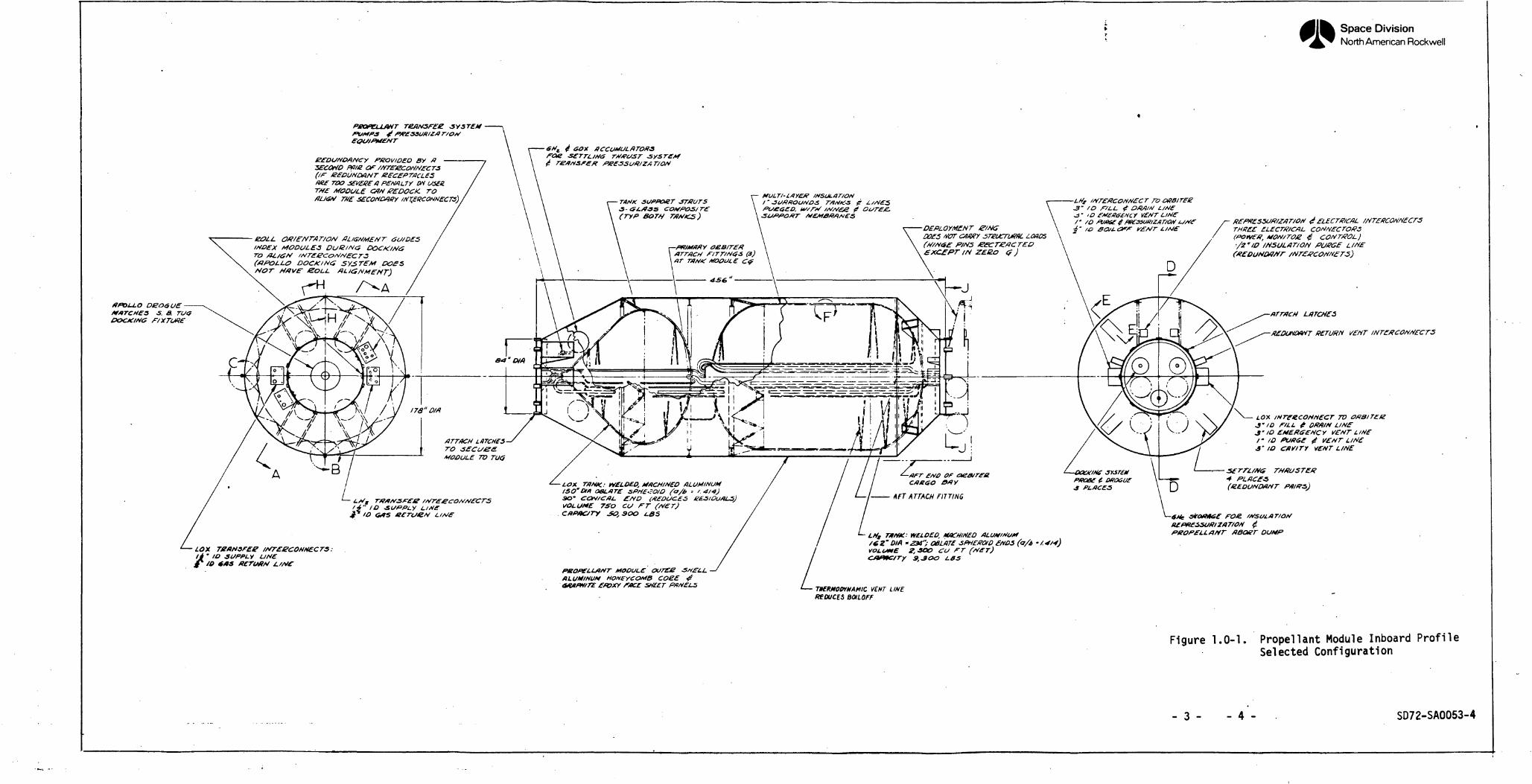
The categories can be developed and defined during Phase A Conceptual andPhase B Definition studies. Figure 1-1 Propellant Module Inboard ModuleProfile depicts the selected configuration which is described in Volume II,Technical Report, and is the source from which the project planning data havebeen derived.
- 2 -
SD72-SA-0053-4
Space DivisionNorth American Rockwell
*f<Di-LO DE06UEtf#TCME3 S. & TU<?DOCXMG F/XTUf1£
EOIHP*£"T
PKOVIOED BY ASECOMO pare(if GEOUNDANT RECEPTACLESOKE TOO j£v£g£a PENALTYTHE MODULE COM eEDOCK. TO
TH£ 3ECONMKY-?" fO f/LL £ O/M/M
• ID fM£ffef£HCY VEfJT L/Mf
DEPLOYMENTDOfS M7T C4MY STZiKTU/fflL LOftOS
THREE £LECTWCAL(POIVfff,EOLL Oft/E'rtT'AT/OM ALIGNMENT GCJ/DES
IHOEX MODULES DuKlNtS£XC£PT IN ZEJZO <} )
DOCK IN d 5Y5TFMMOT HAVE'
LftTCH£S
RETURN VENT
LOX IHTfKCOHHECT TO 0&BITEKID F/LL £ ORA/N LINf
J'/O EMERG£HCY l/Efi/T L/NE/•/a3' IO OW/TY VENT LINE
ATTACH LaTCHfSTOMODULE TO TUG
PIKOE t D8O6UEPLACES
cxeao
AFT ATTACH FITTING
LOU TAMK: WELDED, #»CH/MEOISO"Dia OBLATE SPHEJO/OSOVOLUME 750 CU FTCHPHCJTV £0,300 L8SBCTCHZM L//</£
PKOPELLAHT: WELDED, MOCH/HEO'23t"; OBLATf SPHEKOtD £#O5 (a/I,
VOLUME f,-3OO CU FTLBS
LOX' ID SUPPLY UfitE/O
DUMP
PBOP£LLAf*T MODULE OU71US SHE'LLALUMINUM HONEYCOMB COEEO/MfW/rE £fOXY rtKE SHEET PflrtELS THfRMOlHMAMIC ViNT LINE.
REDUCES BOILOFF
Figure 1.0-1. Propellant Module Inboard ProfileSelected Configuration
- 3 - - 4 - SD72-SA0053-4
Space DivisionNorth American Rockwell
2.0 TEST REQUIREMENTS
This section describes the preliminary ground and orbital flight test programfor attaining an operational capability to perform orbital propellant transferoperations by early 1985. This section is based on Program Level C as definedin Volume II. Development issues and test requirements are identified to pro-vide the basis for developing a disciplined, cost-effective, integrated programconsistent with reliability, safety, and schedule considerations.
The requirements provide the outline for the development, qualification, andacceptance test of the logistics module. These include the early laboratorymaterial and components tests, subsystem tests, and the major ground testarticles. These tests utilize the data derived from, and are a continuationof the supporting research and technology activities discussed in Section 5-
The major areas of concern with respect to the, test requirements in supportof the in-space propellant logistics program are: (1) development testing;(2) test article configuration and utilization; (3) qualification testing;(4) acceptance testing; (5) launch site operations; and (6) flight testing.
The basic ground rules established for this section shall include thefollowing:
a. The logistics module development plan is predicated on aspace-based tug IOC of January 1985.
b. The logistics module IOC is January 1985.
c. Production schedules for operational propellant modules arenot included in the test plans.
d. The data developed in this volume also apply, in general, topropellant modules planned to support 'CIS and RNS via orbitertransport.
The test requirements section study results have served to identify thedevelopment issues and test phases pertaining to the propellant modulesubsystems and interfaces'. Ground and orbital flight test requirementshave been identified in which four ground test articles and one flight testarticle will be utilized. Facility requirements and locations for the con-duct of the test program have been identified. There are no known state-of-the-art constraints in meeting the initial operational capability date.However, propellant transfer in near zero-g environment is a potentialproblem area. The SR&T activity identified and the development testingplanned, including the ground and flight test program, should provide ahigh degree of assurance that an orbital propellant transfer capabilitywill be operational by 1985.
- 5 -
SD72-SA-0053-4
Space DivisionNorth American Rockwell
2.1 DEVELOPMENT TESTING
Development tests are utilized by engineering to select and prove designconcept feasibility by applying induced and natural environments and verify-ing hardware performance through the acquisition and evaluation of data.Informal test procedures are utilized which allow flexibility in the testconduct. Development test requirements are derived through a systemmaticapproach by which the hardware usage is evaluated against parameters such asfunction, environment, failure problem areas, etc. As a result of theevaluation, development issues are identified and logic charts are preparedwhich provide visibility into the resolution of the issues and their relation-ships and constraints.
2.1.1 Development Test Criteria
Typical of the development test criteria to be generated and applied duringthe development phase are:
a. Development requirements will be satisfied by the maximum use of analysis,supported by development tests or a combination of both.
b. Dual usage of major test articles to minimize test hardware is a goal.
c. Test margins, where feasible, will be adequate to protect the test articlefrom destruction. Off limit testing will be utilized at the completion ofthe development program.
d. The test will contribute to verifying the manufacturing process, opera-tional techniques, procedures, and maintenance concepts.
2.1.2 Subsystem Test Requirements
Subsystems tests will be performed to verify the component, subassembly, andsubsystem interfaces and performance. These tests will be performed at out-side vendor facilities and at the contractor's laboratories. The followingparagraphs identify subsystem test requirements.
2.1.2.1 Propellant Module Structure
The primary structure consists of the following major assemblies: a LOX tank,LH2 tank, and outer shell (micrometeoroid shield). Testing of the primarystructure will verify structural integrity for the various operating modes.A laboratory test program will precede the subsystem structural test program.Typical laboratory tests are:
a. Verification and selection of materials and processes
b. Evaluation of integrity of structural joints and related design approaches
c. Ability of outer shell coupon to withstand micrometeoroid impact
A static and dynamic structural test program will demonstrate and verify thestructural integrity and design compliance. These requirements are for critical
- 6 -
SD72-SA-0053-4
Space DivisionNorth American Rockwell
load and environmental conditions. Primary structural test requirements arelisted below.
a. Demonstrate ability of the primary structure to withstand the shuttleboost and touchdown loads.
b. Verify ability of structure to withstand ground handling loads.
c. Demonstrate ability of structure to withstand loads for tug and orbiterdocking.
d. Verify the analysis of tanker modes through a modal vibration test forthe boost and orbital worst case conditions.
2.1.2.2 Thermal Control
The thermal control subsystem consists of the multi-layer insulation andrelated purge, pressurization, and the thermodynamic control systems, LH2 andLOX tank coils and controls, heat exchanger, and overboard vent. Initially alaboratory test program will be required to evaluate materials, components,and subassemblies. Typical laboratory test requirements are:
a. Demonstrate and verify multi-layer insulation thermal efficiency andstructural integrity.
b. Test, evaluate, and demonstrate component performance under simulatedspace operational environment.
c. Demonstrate and evaluate ability of heat exchanger assembly to deliverproper GH2 volume at the proper temperature.
d. Evaluate and verify sensor and control performance.
The thermal control subsystem test requirements follow:
a. Verify the thermal efficiency and performance of the multi-layer insulationunder simulated space environment including ability to vent during ascentand orbit.
b. Verify ability of LH£ and LOX tank to vent properly and that no unnecessaryventing of liquid or vapor occurs.
c. Evaluate and demonstrate ability of tank thermodynamic control LH2conditioning subsystem to allow delivery of propellant to receiver tank atproper temperature and quality.
d. Verify support equipment interface, checkout procedures, and techniques.
2.1.2.3 Docking Subsystem
The Docking subsystem consists o'f the Logistics Module interface structurewhich mates with the swingout fixture in the orbiter and the Logistics Module
- 7 -
SD72-SA-0053-4
Space DivisionNorth American Rockwell
interface structure which mates with the tug. Both interfaces utilize probeand drogue type fixtures with latching capability. Included are the fluid andelectrical line interconnections and redundancy.
Initially a laboratory test program will be required which will serve toevaluate and select materials and components. Typical laboratory test require-ments are:
a. Verify seal, component, and subassembly operation under load, cryogenic,and vacuum environment,
b. Verify the ability of each fluid and electrical interconnection to functionproperly under simulated operating environment after repeated cycling.
The Docking subsystem tests are primarily tc evaluate the functional operationof the Logistics Module interfaces recognizing that the orbiter manipulatorarms will guide and maneuver the logistics module into the orbiter swingoutfixture and the tug into the Logistics Module Docking interface. The testrequirements are:
a. Demonstrate the ability of the aft Logistics Module Docking interface todock and functionally mate with the orbiter swingout fixture underambient and environmental conditions.
b. Demonstrate the functional ability of the forward logistics module dockinginterface to dock with the tug docking interface.
c. Verify items (a) and (b) at outer limits for misaligned conditions.
d. Verify docking interface when the two halves are at different temperatureextremes.
e. Verify ability of the docking interfaces to function properly after re-peated cycling.
2.1.2.4 Propellant Transfer Subsystem
The Propellant Transfer subsystem consists of the following elements.
a. Propellant fill and drain
b. Emergency dump
c. LH2 outlet baffle
d. Tank pressurization(NPSP control)
e. Propellant transfer (liquid expulsion)
f. Propellant gauging
- 8 -
SD72-SA-0053-4
Space DivisionNorth American Rockwell
Laboratory activities will consist of material, component and subassemblytesting, and evaluation and selection. Typical laboratory test requirementsfollow.
a. Evaluate components under simulated operating environment.
b. Demonstrate and evaluate the propellant gauging subassembly performanceat near zero-g conditions.
c. Demonstrate and evaluate the tank pressurization (NPSP) gas generator andpump assembly ability to convert liquid propellant to a gaseous state andcontrol the delivery of the proper gas volume and pressure for pressuriza-tion of the Logistics Module tank ullage.
d. Demonstrate and evaluate liquid transfer pump performance characteristicsunder a space operating environment. Verify ability of pump to deliverproper propellant quantities within the specified NPSP requirementsenvelope.
The Propellant Transfer subsystem test requirements follow.
a. Demonstrate and evaluate the tank pressurization (NPSP) subsystem capabilityto provide proper tank ullage vapor pressure in conjunction with the gasgenerator with resultant subcooled propellants.
b. Demonstrate and evaluate the propellant transfer liquid expulsion subsystemfor ability to deliver propellant to the receiver tank at the properpressures and flow rates including throttled flow.
c. Verify ability of tank propellant gauging system to provide accurate pro-pellant quantity indication for various tank propellant levels.
d. Evaluate failure mode effects on the subsystem.
e. Perform off-limit tests to ascertain operating effect on system performanceand operating envelope.
f. Verify subsystem and related ground support equipment interface, operatingprocedure techniques, and safety considerations.
2.1.2.5 Settling Thruster Subsystem
The Settling Thruster subsystem converts liquid propellant to a gas through aheat exchanger. The gas is stored in an accumulator which supplies thesettling thrusters. In addition, the subsystem contains various valves andcontrols. The subsystem is identical for the LOX and LH2 propellants. Eachconsists of the following basic elements.
a. Propellant turbopump
b. Heat exchanger
- 9 -
SD72-SA-0053-4
Space DivisionNorth American Rockwell
c. Gas generator
d. Accumulator
e. Settling thrusters
f. Related valves and controls
Early laboratory tests will serve to verify the design of the various subsystemelements. Typical laboratory test requirements are:
a. Verify propellant turbopump performance characteristics.
b. Demonstrate ability of pump, heat exchanger, gas generator, and accumulatorassembly to convert propellant into a gas at the proper flow rate and pressure.
c. Verify ability of thrusters to provide thrust for extended duration with-out performance degradation.
The Settling Thruster subsystem test requirements follow.
a. Demonstrate and verify the ability of the thruster subsystem to providepropellant from the Logistics Module tank through the turbopump and heatexchanger to the accumulator at proper flow rate and pressure.
b. Verify the ability of the thruster subsystem to provide GOX and GH2 to thethruster from the accumulator at the proper flow rate and pressure.
c. Determine the settling thruster exhaust impingement pattern on the tankeraft body section and verify no detrimental effects on the logistics moduleexternal surface due to thruster extended duration operation.
d. Determine subsystem performance characteristics for off-limit considerations.
e. Verify subsystem ground support equipment interface, operating procedurestechniques, and related safety consideration.
2.2 GROUND TEST ARTICLE CONFIGURATION AND UTILIZATION
The Logistics Module Development Test Program will require five test articles.This paragraph excludes the Flight Test Article (see paragraphs 2.5 and 2.6)and addresses itself to only the ground test program utilizing the followingfour test articles.
a. Structural static test article
b. Structural dynamic/thermal test articlef
c. Propellant transfer test article
d. Docking subsystem test article
- 10 -
SD72-SA-0053-4
Space Division, North American Rockwell
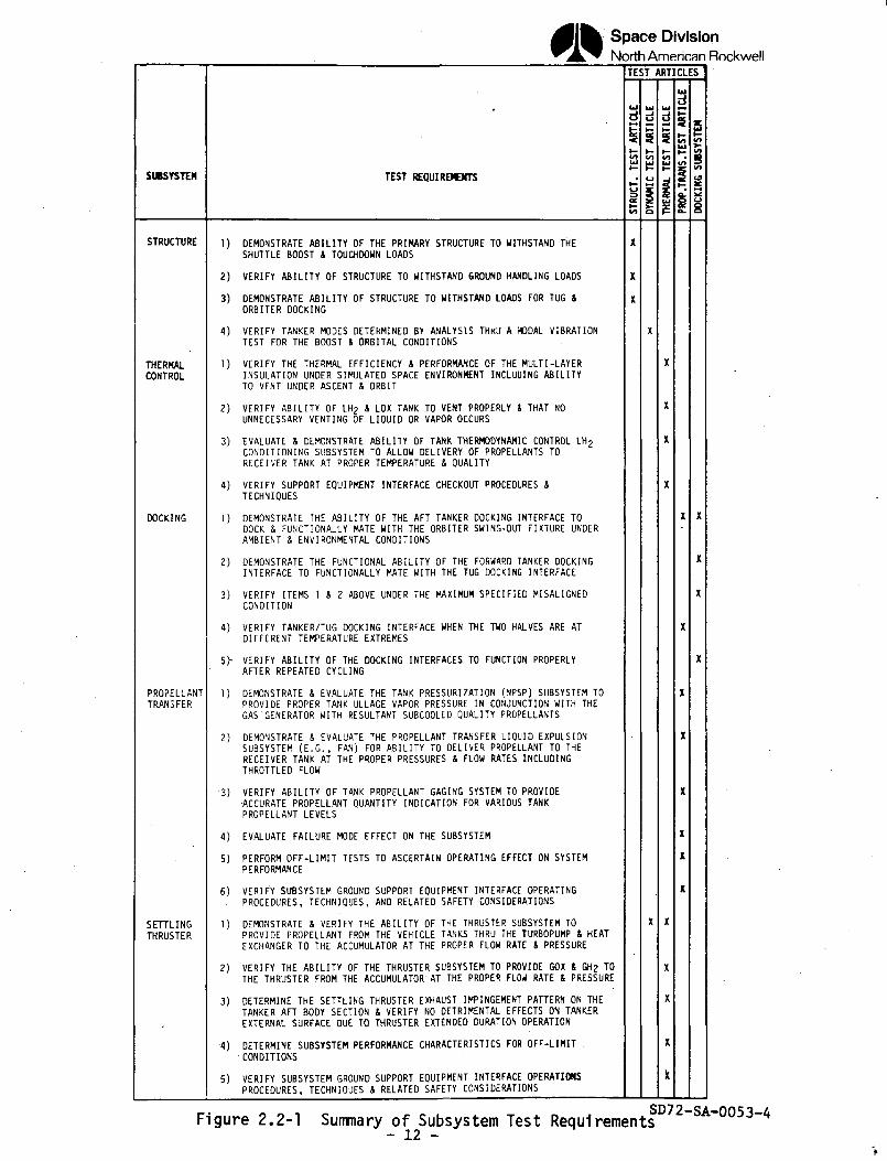
These articles are exclusive of the early laboratory component/subsystem tests.The test objectives and description of each of the test article configurationsare provided .in the following paragraphs. Figure 2.2-1 provides a summary ofthe subsystem primary test requirements and the test article that will beutilized to satisfy those requirements. A goal in planning and scheduling ofthe test activity is the provision for multiple purpose usage of the testarticle. This testing versatility will provide a cost effective approach;however, high risk testing must be scheduled at the end of the test articleactivity to minimize the possibility of damage.
2.2.1 Structural Static Test Article
The prime objective of the Structural Static Test Article is to provide experi-mental verification of the Logistics Module structural integrity for the mostcritical load and environmental conditions.
The Structural Static Article is configured as follows.
a. LOX tank
b. LH2 tank
c. Outer shell
d. Primary orbiter attach fittings (foward)
e. Aft attach fittings
f. Strain gage instrumentation
An alternate test configuration would be the utilization of propellant tankswith multi-layer insulation. This configuration would allow static structuraltesting under cryogenic environment utilizing LN£. However, due to the in-creased weight of the LN2 over LH2, the Logistics Module LH2 tank would requireoff loading. At the completion of structural testing this test article couldalso be used for early ground fit checks with the orbiter. The aft ring wouldbe required on the test article in this case to allow mating with the swing-out ring. The static structural tests may be performed at the NR Seal BeachStructural Test Facility or at the NR Downey Laboratory and Test Facility inBuilding 450.
2.2.2 Structural Dynamic/Thermal Test Article
The structural dynamic/thermal test article activity has been planned to pro-vide multiple purpose usage. The prime objective.of the structural dynamictest article is to verify structural response and resonant frequency characteris-tics through a modal vibration test program. An option that requires investi-gation and possible further consideration is acoustic tests of selected Logisticsmodule sections in the boost configuration. At the conclusion of the dynamictest program the vibration instrumentation will be removed. These tests canbe performed at NASA MSFC.
- 11 -
SD72-SA-0053-4
Space DivisionNorth American Rockwell
SUBSYSTEM
STRUCTURE
THERMALCONTROL
DOCKING
PROPELLANTTRANSFER
SETTLINGTHRUSTER
TEST REQUIREMENTS
1) DEMONSTRATE ABILITY OF THE PRIMARY STRUCTURE TO WITHSTAND THESHUTTLE BOOST & TOUCHDOWN LOADS
2) VERIFY ABILITY OF STRUCTURE TO WITHSTAND GROUND HANDLING LOADS
3) DEMONSTRATE ABILITY OF STRUCTURE TO WITHSTAND LOADS FOR TUG 4ORBITER DOCKING
4) VERIFY TANKER MODES DETERMINED BY ANALYSIS THKU A MODAL VIBRATIONTEST FOR THE BOOST 4 ORBITAL CONDITIONS
1) VERIFY THE THERMAL EFFICIENCY 4 PERFORMANCE OF THE MULTI-LAYERINSULATION UNDER SIMULATED SPACE ENVIRONMENT INCLUDING ABILITYTO VENT UNDER ASCENT 4 ORBIT
2) VERIFY ABILITY OF LH2 4 LOX TANK TO VENT PROPERLY t THAT NOUNNECESSARY VENTING OF LIQUID OR VAPOR OCCURS
3) EVALUATE 4 DEMONSTRATE ABILITY OF TANK THERMODYNAMIC CONTROL LH2CONDITIONING SUBSYSTEM TO ALLOW DELIVERY OF PROPELLANTS TORECEIVER TANK AT PROPER TEMPERATURE 4 QUALITY
4) VERIFY SUPPORT EQUIPMENT INTERFACE CHECKOUT PROCEDURES 4TECHNIQUES
1) DEMONSTRATE THE ABILITY OF THE AFT TANKER DOCKING INTERFACE TODOCK 4 FUNCTIONALLY MATE WITH THE ORBITER SWING-OUT FIXTURE UNDERAMBIENT 4 ENVIRONMENTAL CONDITIONS
2) DEMONSTRATE THE FUNCTIONAL ABILITY OF THE FORWARD TANKER DOCKINGINTERFACE TO FUNCTIONALLY MATE WITH THE TUG DOCKING INTERFACE
3) VERIFY ITEMS 1 4 2 ABOVE UNDER THE MAXIMUM SPECIFIED MISALIGNEDCONDITION
4) VERIFY TANKER/TUG DOCKING INTERFACE WHEN THE TWO HALVES ARE ATDIFFERENT TEMPERATURE EXTREMES
5h VERIFY ABILITY OF THE DOCKING INTERFACES TO FUNCTION PROPERLYAFTER REPEATED CYCLING
1) DEMONSTRATE 4 EVALUATE THE TANK PRESSURIZATION (NPSP) SUBSYSTEM TOPROVIDE PROPER TANK ULLAGE VAPOR PRESSURE IN CONJUNCTION WITH THEGAS GENERATOR WITH RESULTANT SUBCOOLED QUALITY PROPELLANTS
2) DEMONSTRATE 4 EVALUATE THE PROPELLANT TRANSFER LIQUID EXPULSIONSUBSYSTEM (E.G., FAN) FOR ABILITY TO DELIVER PROPELLANT TO THERECEIVER TANK AT THE PROPER PRESSURES 4 FLOW RATES INCLUDINGTHROTTLED FLOW
-3) VERIFY ABILITY OF TANK PROPELLANT GAGING SYSTEM TO PROVIDE•ACCURATE PROPELLANT QUANTITY INDICATION FOR VARIOUS TANKPROPELLANT LEVELS
4) EVALUATE FAILURE MODE EFFECT ON THE SUBSYSTEM
5) PERFORM OFF-LIMIT TESTS TO ASCERTAIN OPERATING EFFECT ON SYSTEMPERFORMANCE
6) VERIFY SUBSYSTEM GROUND SUPPORT EQUIPMENT INTERFACE OPERATING. PROCEDURES, TECHNIQUES, AND RELATED SAFETY CONSIDERATIONS
1) DEMONSTRATE 4 VERIFY THE ABILITY OF THE THRUSTER SUBSYSTEM TOPROVIDE PROPELLANT FROM THE VEHICLE TANKS THRU THE TURBOPUMP 4 HEATEXCHANGER TO THE ACCUMULATOR AT THE PROPER FLOW RATE 4 PRESSURE
2) VERIFY THE ABILITY OF THE THRUSTER SUBSYSTEM TO PROVIDE GOX 4 GH2 TOTHE THRUSTER FROM THE ACCUMULATOR AT THE PROPER FLOW RATE 4 PRESSURE
3} DETERMINE THE SETTLING THRUSTER EXHAUST IMPINGEMENT PATTERN ON THETANKER AFT BODY SECTION 4 VERIFY NO DETRIMENTAL EFFECTS ON TANKEREXTERNAL SURFACE DUE TO THRUSTER EXTENDED DURATION OPERATION
•4) DETERMINE SUBSYSTEM PERFORMANCE CHARACTERISTICS FOR OFF-LIMIT .CONDITIONS
5) VERIFY SUBSYSTEM GROUND SUPPORT EQUIPMENT INTERFACE OPERATIONSPROCEDURES, TECHNIQUES 4 RELATED SAFETY CONSIDERATIONS
TEST ARTICLES
S
Figure 2.2-1 Summary of Subsystem Test Requirements- 12 -
SD72-SA-0053-4
Space DivisionNorth American Rockwell
The prime objective of the Thermal Test Article is to evaluate and verify theperformance of the thermodynamic control subsystem.
2 .2 .2 .1 Structural Dynamic Test Article
The structural dynamic test article consists of the following elements.
a. LOX tank (with multi-layer insulation)
b. LH2 tank (with multi-layer insulation)
c. Outer shell
d. Thermodynamic control subsystem
o Valves and controlso Heat exchanger
e. Settling thruster subsystem
1. LC>2 and LH.2 heat exchangers (one each)2. L02 and LH2 gas generators (one each)3. LC>2 and LH2 accumulators (one each)4. L02 and LH2 turbopump (one each)
f. Test instrumentation accelerometers
g. Simulated masses for propellant transfer components
The structural dynamic tests can be performed at MSFC.
2 . 2 . 2 . 2 Thermal Test Article
The thermal test article configuration is the same as for the structural dyn-amic test article except that the structural dynamic test instrumentation willbe removed and thermocouples added for the acquisition of thermal data. Simu-lated component masses will also be removed for the thermal tests. Thethermal test can be performed at the NASA Mississippi Test Facility.
At the successful completion of the thermal tests the test article will beshipped to MSC to undergo thermal vacuum tests. The objectives of these testsare to verify the performance of the multi-layer insulation under simulatedascent, orbital, and descent environmental conditions. During these tests theability of the system to vent during ascent and pressurize during descent willbe verified. The propellant tanks will be pre-chilled and conditioned withcooled helium gas with the insulation purged and sampled for tank leaks.
- 13 -SD72-SA-0053-A
Space DivisionNorth American Rockwell
2.2.3 Propellant Transfer Test Article
The prime objective of the propellant transfer test article is to demonstrateand evaluate the ability of the propellant transfer subsystem to deliver pro-pellant to the receiver tanks at the required pressure and flow rates. Thetest article is an all-systems flight configured vehicle with simulated tugreceiver propellant tank interface and propellant tanks for performing pro-pellant transfer in a one-g environment.
The propellant transfer test article consists of the following elements.
a. LOX tank (with multi-layer insulation)
b. LH2 tank (with multi-layer insulation)
c. Outer shell
d. Thermodynamic control subsystem
e. Forward and aft docking subsystem
f. Propellant transfer subsystem
g. Settling thruster subsystem
h. Simulated tug/logistics tank interface with insulated receiver propellanttanks
i. Propellant and electrical interconnects between tanker and orbiter
j. Pneumatic actuation, pressurization, and purge systems
Docking tests under cryogenic conditions will be performed utilizing thepropellant transfer test article. The NASA Mississippi Test Facility or NRSanta Susana Propulsion Test Facility are candidate facilities that couldsupport these test activities.
2.2.4 Docking Subsystem Test Article
The prime objective of the Docking subsystem is to evaluate and verify thedocking subsystem operation at the maximum misalignment and temperature dif-ferential conditions.
The docking subsystem test article configuration consists of the followingelements.
a. Forward drogue section including propellant and electrical interconnections
b. Aft docking system probe and drogue assembly including propellant andelectrical interconnection
c. Simulated tug interface including propellant and electrical interface
- 14 -
SD72-SA-0053-4
Space DivisionNorth American Rockwell
For the docking tests under cryogenic conditions the propellant transfer testarticle will be utilized. Ambient testing could be performed at the NR DowneyFacility. Testing under cryogenic conditions may be performed at the NRSanta Susana Propulsion Test or NASA Mississippi! Test Facilities.
- 15 -
SD72-SA-0053-4
Space DivisionNorth American Rockwell
2.3 QUALIFICATION TESTING
Qualification tests are performed on flight-type hardware to.demonstrate andverify that the hardware and related manufacturing..processes meet design andspecification requirements. The hardware is functionally operated whileexposed to ambient and operational environmental conditions. These tests willserve to verify that design margins are adequate with hardware environmentalexposures greater than experienced during logistics module ground and flightoperations. Reliability evaluation and assessments provide analytical valida-tion for verification of the test program phases consistent with confidencegrowth considering schedule, risk and safety. Test procedures are documentedand conducted on a formal basis.
The qualification test phase is part of an overall integrated test program.The qualification requirements are derived during the design phase froman analysis of each equipment item's performance and environmental ex-posure during the mission, utilizing factors' such as hardware criticality,past hardware history and test effectiveness. Subcontractor qualificationtest activities including test requirements and schedule are directlyrelated to and managed through the contractor integrated test plan.
Typical criteria that will be generated and applied to the qualificationtest phase are:
a. Qualification requirements will be satisfied by analysis or test andmay be a combination of both.
b. Qualification testing will be based on hardware functional criticalitywhich would result in propellant module and/or shuttle loss.
c. Redundant path qualification testing is required when redundancyprecludes a single point failure.
d. Hardware requalification is a requirement when a design or manufacturingprocess change has occurred.
2.4 ACCEPTANCE TESTING
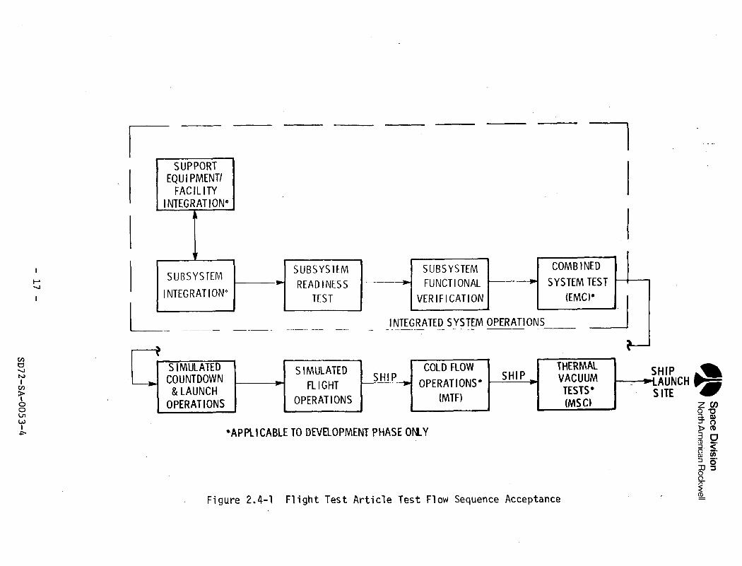
Acceptance tests are conducted on deliverable flight and support equipmentthat will demonstrate and verify that the hardware conforms to specificationrequirements. Test environmental levels are in general no greater than willbe experienced during ground and flight operations. These tests are performedat all hardware levels, i.e., materials, components, subassembly, subsystemand vehicle, as each item is ready for delivery to the next assembly or usagepoint. The tests involve supplier and contractor testing and continue throughpropellant module acceptance by the customer. All tests are performed toformal procedures and documentation. The operational logistic module flightoperations are discussed under Volume II, Section 9.0. Ground operations arediscussed under Volume II Section 9.0 and in Section 4.0 of this volume. Thefollowing paragraphs describe tests and procedures which are representativeof the operational propellant module as well as the flight test article.Test requirements that are peculiar to the flight test article are identified.Figure 2.4-1 presents a block diagram of the flight test article test flowsequence from the contractor's facility to the launch site.
- 16 - SD72-SA-0053-4
Space
Div
isio
nN
orth A
merican R
ockwell
oLUCO
1o_LU
O_
OQ_
Q.
0)oc(C•)->Q.
<DOO0)o0)3O"
OJoo-pw»03O
)r-OO)
O)
- 17
-
SD72-SA
-0053-4
Space DivisionNorth American Rockwell
Typical of the acceptance test criteria to be generated and applied tothe acceptance test phase are:
a. All deliverable end items will receive an acceptance test.
b. Parallel paths or alternate mode operations will be demonstrated.
c. Supplier subsystem acceptance testing procedures will be utilizedat the contractor facility to the maximum extent feasible.
d. Whenever a subsystem module interface connection has been dis-rupted or a spare installed, reverification of the disrupted hardwareis a requirement..
e. Logistics module post-manufacturing operations will be conductedunder ambient conditions.
2.4.1 Post-Manufacturing Checkout
Post-manufacturing checkout operations are performed subsequent to thepropellant module assembly and installation of the subsystems. The objec-tive is to verify the compatibility of the subsystems and related supportequipment. The support equipment and facilities will have been integratedand verified prior to interfacing with the module.
2.4.2 System Test
System test covers the operations performed on the logistics module atthe contractor facility leading to acceptance. Each of the subsystemswill undergo a readiness phase in preparation for subsystem functional veri-fication. Subsystem readiness entails the servicing, calibration andverification that the subsystem is ready for the conduct of subsystemfunctional test. Functional verification tests provide for exercise ofthe subsystem through the operational modes including parallel path (backup).At the completion of subsystem verification the module is ready for com-bined system test. Combined system test provides verification that themodule and related support equipment function satisfactorily as a compositesystem with in-depth performance verification monitoring through the supportequipment. During combined systems operations the flight article onlywill undergo electromagnetic compatibility tests. The module will be in-strumented and the command and response data recorded. The data will bereviewed to determine that no adverse effect exists from spurious and/ortransient signals.
A simulated launch pad countdown operation will be performed next. Themodule/orbiter interface electrical connection will be utilized to stimulatethe module and verify responses. This operation will serve to demonstrateand verify launch pad test procedures and verify the module/orbiter interface,
- 18 -SD72-SA-0053-4
Space DivisionNorth American Rockwell
Simulated flight operations will be performed next. These operations,utilizing the orbiter and/or tug interface will serve to simulate theflight phases consisting of boost, ascent, and orbital operations. Theseoperations involve shuttle/module and tug docking, propellant transferfrom module to the tug, return and securing the module in the shuttle,descent and landing. At the conclusion of simulated flight operationsthe module is accepted.
2.4.3 Propellant Module Environmental Tests
The module will be shipped to the NASA MTF test site for the purpose ofconducting propellant cold flow operations. These operations will verifythe module's manufacturing process and system performance under a cryogenicenvironment. During the propellant fill and drain operations, valve per-formance will be verified, effect of cryogenic exposure on the multi-layerinsulation ascertained and tank leakage checked. At the successful con-clusion of the cold flow operations the module will be shipped to theMSC Space Environment Simulation Laboratory for thermal vacuum tests. Thesetests will verify that the module operates satisfactorily in a space-simulated environment and that the multi-layer insulation vents satis-factorily during ascent and can be pressurized during simulated descent.The module will next receive an integrated system test under ambient con-ditions to verify that no detrimental effects from environmental testinghave occurred. The module will then be transported to the launch site. Theenvironmental tests are not applicable to the operational propellant modules.
2.5 LAUNCH SITE OPERATIONS
The discussion in this section pertains to the peculiar propellant moduleflight test article launch site test and operations requirements foractivation and launch preparation. Operational propellant module launchsite operations are discussed in Volume II, and Section 4.0 of this volume.The prime objective of the flight test article launch site operations isto initially activate and verify the launch site facility/support equip-ment and propellant module/orbiter interface compatibility procedures andtechniques, and provide training for operations personnel. The launchsite locations are:
a. Propellant module maintenance and checkout area
b. Shuttle/orbiter loading bay area
c. Vehicle Assembly Building
d. Launch pad
2.5.1 Maintenance and Checkout Area
The logistics module maintenance and checkout area initial operationswill provide for activation and verification of the compatibility of theground support equipment, facility and propellant module. These operations
- 19 -
SD72-SA-0053-4
Space DivisionNorth American Rockwell
are similar to the final logistics module acceptance operations performedat the contractor facility. Post-flight operations are also performed inthis area and will serve to demonstrate the propellant module maintenanceconcept involving scheduled and unscheduled maintenance (i.e., partsremoval and replacement, repair, and turnaround) techniques and procedures.
2.5.2 Shuttle Orbiter Loading Bay Area
The initial operations in the shuttle orbiter loading bay area willverify:
a. Procedures and techniques for handling, loading and unloadingthe module from the shuttle orbiter.
b. Module/orbiter physical, mechanical and electrical interface.
c. Checkout procedures and techniques.
d. Orbiter manipulator arm and swingout ring compatibility with themodule.
Manipulator arm and swingout ring compatibility verification tests mustrecognize that these operations, from a structural integrity standpoint,are normally performed under zero-g orbital conditions. The test articlewill be instrumented with accelerometers and strain gauges for acquisitionof load data for verification that the handling, loading and unloading oper-ations do not exceed structural design requirements.
An alternate consideration is the utilization of the structural test articlefor early verification of the module/shuttle physical structure and mechan-ical interface compatibility as it pertains to items (a), (b), and (d)above. The test article would require retrofit with electrical and propel-lant interface connections.
2.5.3 Vehicle Assembly Building
The Vehicle Assembly Building operations entail (1) erection and mating ofthe shuttle orbiter (including module payload) with the booster on thelaunch umbilical tower; (2) non-hazardous type operations involving checkoutof the module through the shuttle/launch umbilical tower/launch controlcenter.
Initial operations will verify the effect on the module structure due tothe handling and erection of the orbiter. During these operations straingage and accelerometer data will be acquired for evaluation and verificationthat structural design limits are not exceeded.
Early module checkout operations will verify the facility/shuttle andorbiter/module electrical interfaces. These operations entail the checkoutof the module through the launch control center during which test proceduresand techniques will be evaluated and verified.
- 20 -
SD72-SA-0053-4
Space DivisionNorth American Rockwell
If early structural and mechanical physical fit checks with the orbiterare required, the structural test article could be utilized for thispurpose.
2.5.4 . Launch Pad Operations
The prime objectives of the propellant module flight test article launchpad operations are to: (1) verify the module/shuttle/facility interfaces,countdown procedures and techniques; (2) demonstrate compatibility of themodule/shuttle under cryogenic conditions; (3) provide launch crew training;and (4) demonstrate and verify that the operations and procedures for theoperational logistics module are satisfactory.
The launch pad operations provide the first opportunity for demonstratingthe compatibility of the module/shuttle/launch pad and control centercompatibility. Initially, continuity tests will verify wiring interfaces,.EMI tests will be conducted to verify that no induced interference existsbetween module shuttle, and facility. Propellant fill and drain testswill demonstrate the adequacy of the system to transfer propellant fromthe facility into the module through the shuttle interface. In demon-strating countdown abort operations, the ability to transfer the propellantfrom the module to the ground facility, and the purge, vent, safing andsecuring operations will be verified. Finally, the flight test articlecountdown and launch will demonstrate and verify the production moduleand launch pad operations and procedures. An alternate consideration ifearlier launch pad propellant transfer operations with the orbiter andmodule is required, is the utilization of the thermal test article as apropellant module simulator.
2.6 FLIGHT TEST
The prime objective of the flight test program is to demonstrate and verifythe logistics module design and operational concept for the boost, ascent,orbit, descent, landing, and turnaround conditions. One flight test articlewill be utilized for conducting a series of flight tests which will lead tothe demonstration and certification of a man-rated propellant module. Fourflights as a minimum have been specified. Preflight, flight, and post-flight operations for the operational module are described in Volume II andSection 4.0 of this volume. The flight test article will be instrumented toacquire additional data for evaluation of the logistics module subsystemperformance. The instrumentation package could be interfaced with the tugfor RF data transmission to the orbiter or ground station. Duringthe module/orbiter operations, additional data pertaining to the logisticsmodule subsystem performance could be acquired by recorders in the cargo
compartment.
The initial logistics module flight would be accomplished using LN2 in placeof LOX and LH2 propellants in order to minimize hazards. The logisticsmodule LH.2 tank would be off-loaded since LN2 is heavier than LH2- Thisflight test will demonstrate and verify module deployment and tug/moduledocking and hookup including pre-transfer module checkout. Additionalobjectives are to separate the logistics module from the shuttle
- 21 -
SD72-SA-0053-4
Space DivisionNorth American Rockwell
and demonstrate a partial propellant emergency dump and then return anddemonstrate manipulator arm capture and module docking with the shuttle.Once the module is in the shuttle cargo bay, an emergency propellant dumpof the remaining propellant will be demonstrated. This operation willdetermine the effect, if any, of propellant dump on the orbiter withregard to propellant pattern, impingement and window fogging. Further,flight test #1 objectives are to evaluate and verify descent and touchdownloads, safing procedures, maintenance, and turnaround operations.
Flight Test #2 objectives are to demonstrate and.evaluate the module-tugorbital propellant transfer operations under 10 to 10 -g acceleration.During these operations the performance of the docking thermal controland propellant transfer subsystems will be evaluated. This operation willdemonstrate a single tug/module propellant transfer. The module withresidual propellant, if any, will be returned to the orbiter and undergopropellant dump.
Flight Test #3 objectives are to evaluate module operations for twopropellant transfer demonstrations. During these operations the tugwould dock with the module separate from the orbiter and undergo propellanttransfer operations and return the module to the orbiter. These operationswould then be repeated. The second propellant transfer operation would beevaluated for module propellant separation and vortexing characteristicsand performance.
Flight Test //4 objectives would consist of demonstrating and verifyingtwo additional tug propellant transfer operations. The satisfactory com-pletion of these operations and their verification through data evaluationwill provide propellant module man-rated certification which will coincidewith initial operational capability.
- 22 -SD72-SA-0053-4
Space DivisionNorth American Rockwell
3.0 SCHEDULES AND MILESTONES
This section contains the preliminary test schedule and milestones thatare a result of satisfying the test requirements discussed in Section 2.0of this volume. The schedule pertaining to new facility and ground supportequipment is discussed under Section 4.0 of this volume. The SupportingResearch and Technology schedule and related discussion is covered under
Section 5.0 of this volume. A preliminary master propellant module imple-mentation development schedule that incorporates the study results of thisvolume is presented in Section 6.0. The schedule depicts the major stepsto be taken for establishing module propellant logistics orbital capabilityby early 1985.
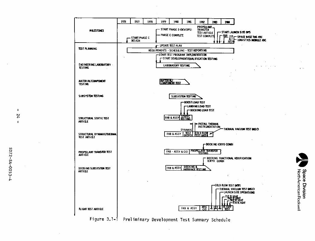
Figure 3.1-1, Preliminary Development Test Summary Schedule, provides themilestones, events, and activities to accomplish the manufacturing and testoperations to satisfy the program development, qualification, andacceptance test requirements. The ground test schedule allows for flighttest article modification if problems arise during development testing.
The test schedule activities cover a duration of approximately eight years,starting with test planning and culminating with the last flight of thetest article and an IOC date of January, 1985, which coincides with the IOCof the tug. Test planning activities begin in the last quarter of 1976,concurrent with the start of Phase C design of the selected configuration.During this activity, test requirements will be established and documentedin a test program plan. Phase C activities culminate in January, 1979, andPhase D development/operations begin and are performed for a duration ofsix years. During this phase the development test plan will be updated andrequirements will be implemented. Early testing will consist of laboratorymaterial selection and component testing, followed by the subsystem testphase culminating in the second quarter of 1982.
Five major test articles will be manufactured, assembled and tested duringthe development test program. Manufacturing, assembly, and acceptancetest operations of the test articles at the contractor's facility willcover a duration of approximately three and one-half years, culminating inthe first quarter of 1983. These operations will commence with the struc-tural static test article, mid-1979, and conclude with the shipment of theflight test article to MSFC for cold flow tests.
The development ground test program covers a period of approximatelythree and one-quarter years beginning in the last quarter of 1980 at thestart of the structural static test program and culminating with thepropellant transfer test article operations in the last quarter of 1983.The structural static test article operations will be performed for aduration of nine months ending in the third quarter of 1981. The struc-tural dynamic/thermal test article covers a duration of approximately twoand one-quarter years, beginning in the first quarter of 1981, and cul-minating in the first quarter of 1983. During this period, structuraldynamic tests will be performed at MSFC. Cold flow tests will be performedat MTF culminating with thermal vacuum tests at MSC.
- 23 -SD72-SA-0053-A
Space
Div
isio
nN
orth A
merican
Rockw
ell
CL -
- /
—
rMS
QJ
-Oo>oGO(O
I/Otod)
O)
CL
o(1)>CDQfO0)
Q.
euIaij-
ii«K?£ ujU
i P
s§1
- 2
4 -
SD72-SA
-0053-4
Space DivisionNorth American Rockwell
The propellant transfer test article operations are conducted for a durationof two and one-half years beginning in mid 1982 and are completed at theend of 1983. The docking subsystem test article operations begin in 1981and are conducted for a duration of approximately 21 months. Interfacewith the propellant transfer test article for docking tests under cryogenicconditions will occur in the third quarter of 1982.
The flight test article initial launch site ground operations begin inthe last quarter of 1983 and continue for four months culminating in thefirst launch and flight. Three additional flights will cover a durationof 10 months and terminate with an IOC of January, 1985.
- 25 -SD72-SA-0053-4
Space DivisionNorth American Rockwell
4.0 NEW FACILITIES AND GROUND SUPPORT EQUIPMENT
4.1 FACILITY REQUIREMENTS
The objective of this portion of the study..has been to identify and describethe impact that the In-Space Propellent Logistics program will have on thevarious Government facilities and equipment. The criteria used to evaluatethis impact were based upon the utilization of the drop tank shuttle orbiter/liquid propellant booster configuration baseline, the utilization of alogistics module (59,000 pounds maximum propellant capacity), located in thecargo bay of the shuttle, the utilization of the five space t raff ic programlevel concepts A, B, C, D, and E, and the maintainability of the maximumlevel of safety for facility equipment, ground support equipment, flightvehicle equipment, ground personnel, and flight crew personnel.
The major areas of concern with respect to facility requirements in supportof in-space propellant logistics systems have been developed into fourcategories of e f for t , consisting of: (1) the determination of liquid oxygenand hydrogen manufacturing and delivery capabilities for each of the variousspace traffic program levels; (2) the determination of the propellantlogistics module loading timelines, with respect to propellant flow rates,transfer line sizes, and loading controls and sequences; (3) the determin-ation of additional and modified facilities and equipment in support of thelogistics module flight and test articles, from design tests and post-manufacturing checkout to post-flight safing and checking operations; and(4) the development of timeline schedules, for effort required to modify 'those facilities.
Although this portion of the study effor t was limited in scope, sufficientinformation has been developed to bring into proper perspective, the effectof those additional requirements imposed on the Government facilities in orderto support the In-Space Propellant Logistics program. The conclusions estab-lished herein are based upon optimum technical feasibility, operationalcompatibility, safety considerations, and cost minimization, and can be sum-marized as follows: ;,
a. Modification of existing liquid oxygen manufacturer's facilities willbe required to support space t raff ic program levels D and E for CIS andRNS.
b. The existing (Saturn V) liquid hydrogen manufacturer's facility capacityis capable of supporting all of the space t raff ic program levels.
c. The liquid oxygen and hydrogen utilization impact due to the propellantlogistics requirements is minimal compared to the total shuttle propel-lant requirements.
d. Liquid' oxygen and hydrogen series loading of the logistics module wasselected because of the lower hazard risks involved.
e. Independent ground control for loading the logistics module was selectedbecause various potential hazards would be reduced.
Preceding Page Blank - 27 -SD72-SA-0053-4
Space DivisionNorth American Rockwell
f. Small propellant transfer lines (two-inch nominal diameter) are adequateto provide the maximum flow rates for the logistics module, within theshuttle loading timelines, and safe emergency drain time.
g. Minimal modifications and additions are anticipated for the KSC launchfacilities.
h. Relatively extensive modifications are anticipated at the other facili-ties (new and modified platforms, tie-down structure, fluid and cabledistribution systems, etc.).
i. In-space traffic program levels A, B, and C can be supported utilizingone launch pad, and as many as four launch pads may be required tosupport the highest t raff ic level E (CIS).
j. The facility modification and activation implementation schedules aresupportive to the in-space logistics programmed initial operationalcapability of January, 1985.
4.1.1 Propellant Manufacturing Capabilities
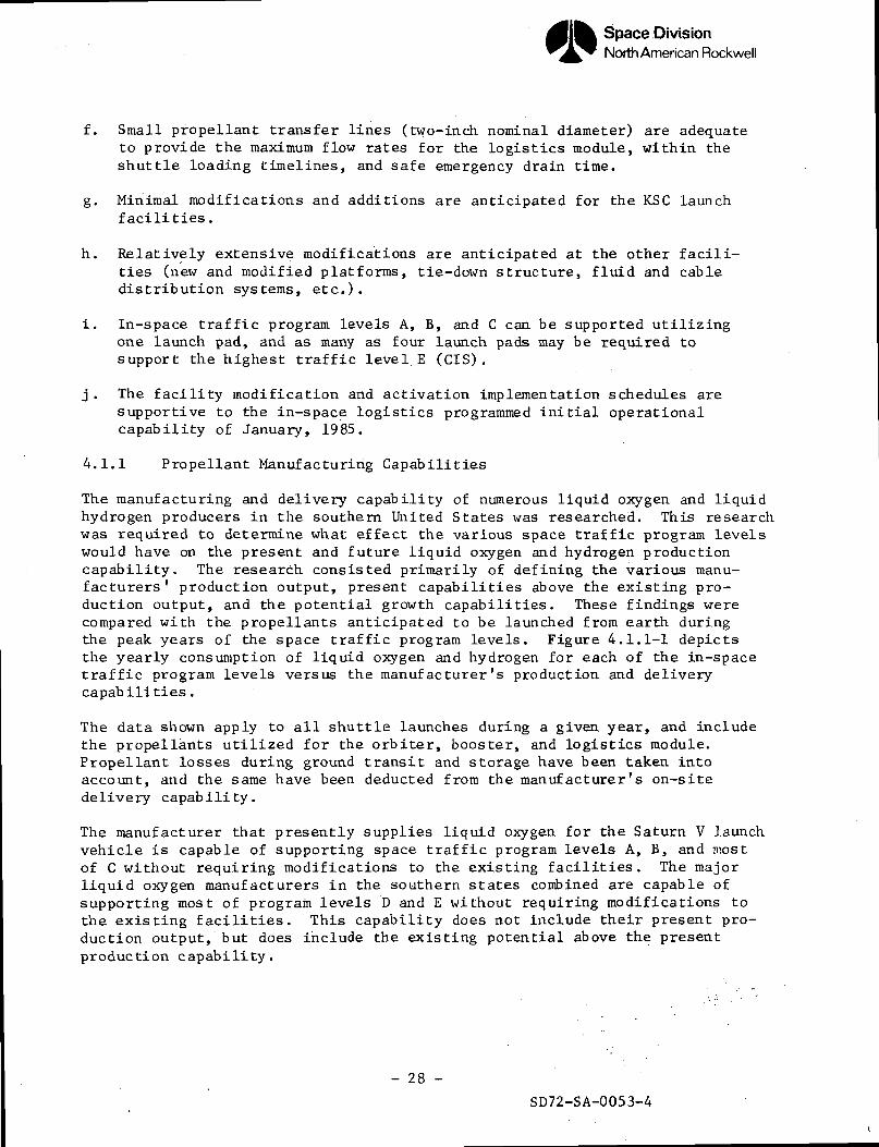
The manufacturing and delivery capability of numerous liquid oxygen and liquidhydrogen producers in the southern United States was researched. This researchwas required to determine what effect the various space traffic program levelswould have on the present and future liquid oxygen and hydrogen productioncapability. The research consisted primarily of defining the various manu-facturers' production output, present capabilities above the existing pro-duction output, and the potential growth capabilities. These findings werecompared with the propellants anticipated to be launched from earth duringthe peak years of the space t raff ic program levels. Figure 4.1.1-1 depictsthe yearly consumption of liquid oxygen and hydrogen for each of the in-spacetraff ic program levels versus the manufacturer 's production and deliverycapabilities.
The data shown apply to all shuttle launches during a given year, and includethe propellants utilized for the orbiter, booster, and logistics module.Propellant losses during ground transit and storage have been taken intoaccount, and the same have been deducted from the manufacturer's on-sitedelivery capability.
The manufacturer that presently supplies liquid oxygen for the Saturn V launchvehicle is capable of supporting space t raff ic program levels A, B, and mostof C without requiring modifications to the existing facilities. The majorliquid oxygen manufacturers in the southern states combined are capable ofsupporting most of program levels D and E without requiring modifications tothe existing facilities. This capability does not include their present pro-duction output, but does include the existing potential above the presentproduction capability.
- 28 -
SD72-SA-0053-4
Space DivisionNorth American Rockwell
450-1
400-
350-
X 300-O
O
250-
200-
150-
100-
50
MODIFICATION TO MFC FACILITY CAPABILITY~E~CIS)
D (CIS)EXISTING COMBINED SOUTHERN''
STATES MFC CAPABILITY // E (RNS)
EXISTING MFC CAPABILITY
i1980 1982 T984
YEAR1986 1988
CNX
Zo
24-
20-
16-
8-
4-
EXISTING MFC CAPABILITY
E (CIS)
D (CIS)E (RNS)D (RNS)
1980 1982
—i 1— r~1984 1986 1988
YEAR
Figure 4.1.1-1 LOX and LH2 Manufacturing Requirements- 29 - SD72-SA-0053-4
Space DivisionNorth American Rockwell
In order to support program levels D and E for CIS and RNS during the peakyears, it would require modification to the manufacturer's existing facili-ties. Various liquid oxygen manufacturers indicated that to meet theseincreased production requirements, modifications to their present facilitiesor the installation of new facilities could be accomplished expeditiouslywith no foreseeable problems. The liquid oxygen utilization impact due tothe in-space propellant logistics requirements (i.e., that propellant trans-ported in the logistics module) is considered minor compared to the totalshuttle propellant requirements. The logistics module usage is approximatelyone percent of the total liquid oxygen requirements.
The manufacturer that presently supplies liquid hydrogen for the Saturn Vlaunch vehicle is capable of supporting all of the space traffic programlevels without requiring modifications to the existing facilities. Theliquid hydrogen utilization impact due to propellant logistics requirementsis considered minor compared to the total shuttle propellant requirements.The logistics module usage is approximately 5 percent of the total liquidhydrogen requirements.
4.1.2 Propellant Logistics Module Loading Requirements
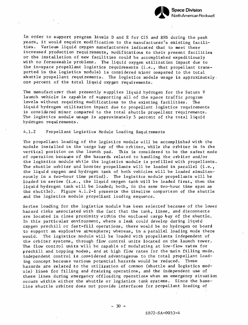
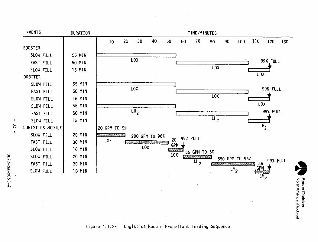
The propellant loading of the logistics module will be accomplished with themodule installed in the cargo bay of the orbiter, while the orbiter is in thevertical position on the launch pad. This is considered to be the safest modeof operation because of the hazards related to handling the orbiter and/orthe logistics module while the logistics module is prefilled with propellants.The shuttle orbiter and booster propellants will be loaded in parallel (i.e.,the liquid oxygen and hydrogen tank of both vehicles will be loaded simultan-eously in a two-hour time period). The logistics module propellants will beloaded in series (i.e., the liquid oxygen tank will be loaded first, then theliquid hydrogen tank will be loaded; both, in the same two-hour time span asthe shuttle). Figure 4.1.2-1 presents the timeline comparison of the shuttleand the logistics module propellant loading sequence.
Series loading for the logistics module has been selected because of the lowerhazard risks associated with the fact that the tank, lines, and disconnectsare located in close proximity within the enclosed cargo bay of the shuttle.In this particular environment, where a leak could develop during liquidoxygen prechill or fast-fill operations, there would be no hydrogen on boardto support an explosive atmosphere; whereas, in a parallel loading mode therewould. The logistics module will be loaded with propellants independent ofthe orbiter systems, through flow control units located on the launch tower.The flow control units will be capable of modulating at low-flow rates forprechill and topping modes, and at high flow rates for the main filling mode.Independent control is .considered advantageous to the total propellant load-ing concept because various potential hazards would be reduced. Thesehazards are related to the utilization of common (shuttle and logistics mod-ule) lines for filling and draining operations, and the independent use ofthese lines during emergency offloading operations when an emergency situationoccurs within either the shuttle or logistics tank systems. Since the base-line shuttle orbiter does not provide interfaces for propellant loading of
- 30 -
SD72-SA-0053-4
Space
Divisio
nN
orth A
merican R
ockwell
oCO
oe\j
CT>cn
IS)
ooocr>o00
oinoCO
oCM
Xocr>
Xo
Xo
g
Xo
enoo.
CD
C\J
CM
CM
VO
a.
CJ3
ooCM
LOoQ-
CD
OCM
XO
Xo
aioc:O)
a)(/i01
•oraoCDQ.
O&-a.O)
-ootooen
OICM
^a-OJ
m
CD
in
in
o
LO
LO
LO
I—
LO
LO
I—
O
O
CD
O
O
OCM
C
O
i—
CM
C
O
i—
Qo
Q:
UJ
o oo
-j <
c3 a: 3
O
LLJ O
_J I-
-J^
g 0
0
0£o
o o
_l
_J
oo oo
^
00
Ll_
g " »O
H
- O
-J
oo
_i
«>O
i—i
OO
U-
U.
2 2
o o
—I
_loo
oo«C
J
Ll_ 00
- 31
-
SD
72
-SA
-00
53
-4
Space DivisionNorth American Rockwell
of the logistics module, it is also considered imperative from a safe oper-ations standpoint, that the liquid oxygen and hydrogen fill and drain linesinterfaces be separated, and located such as to prevent potential vapor mix-ing hazards.
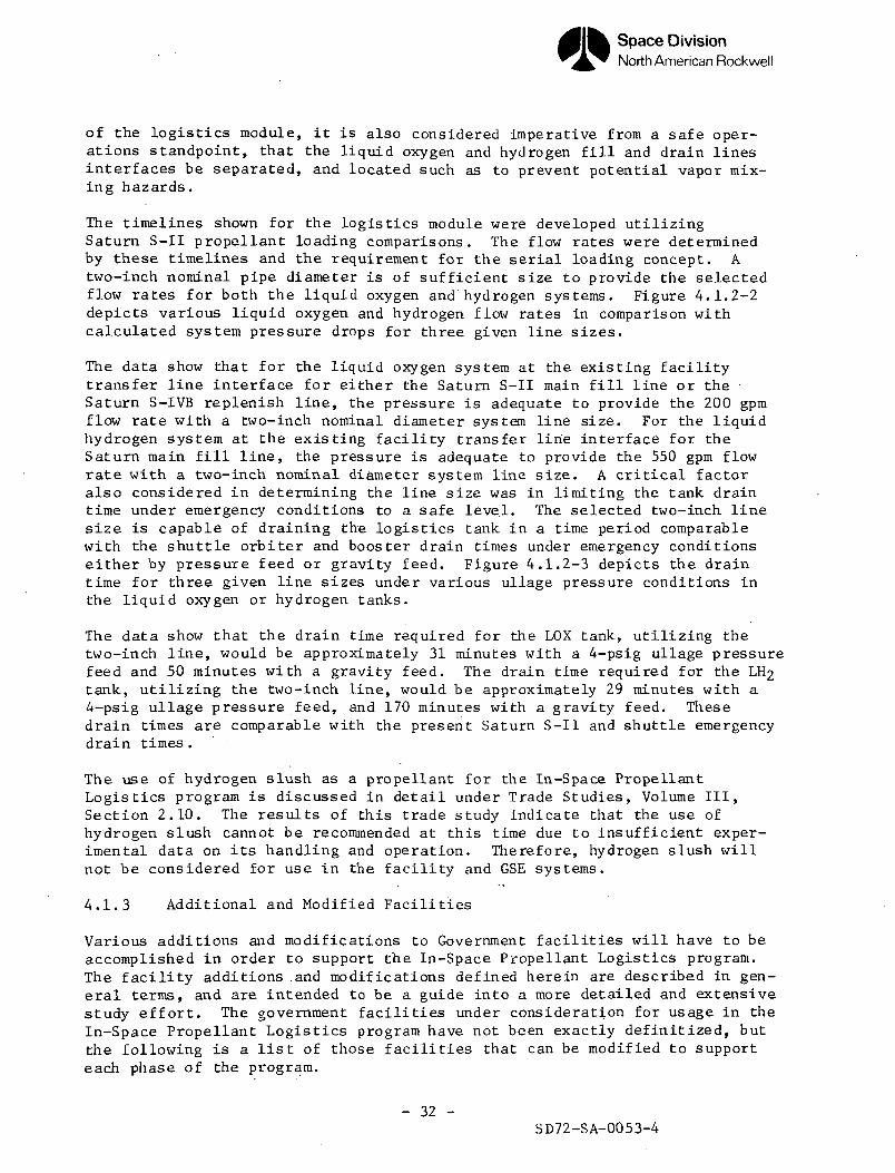
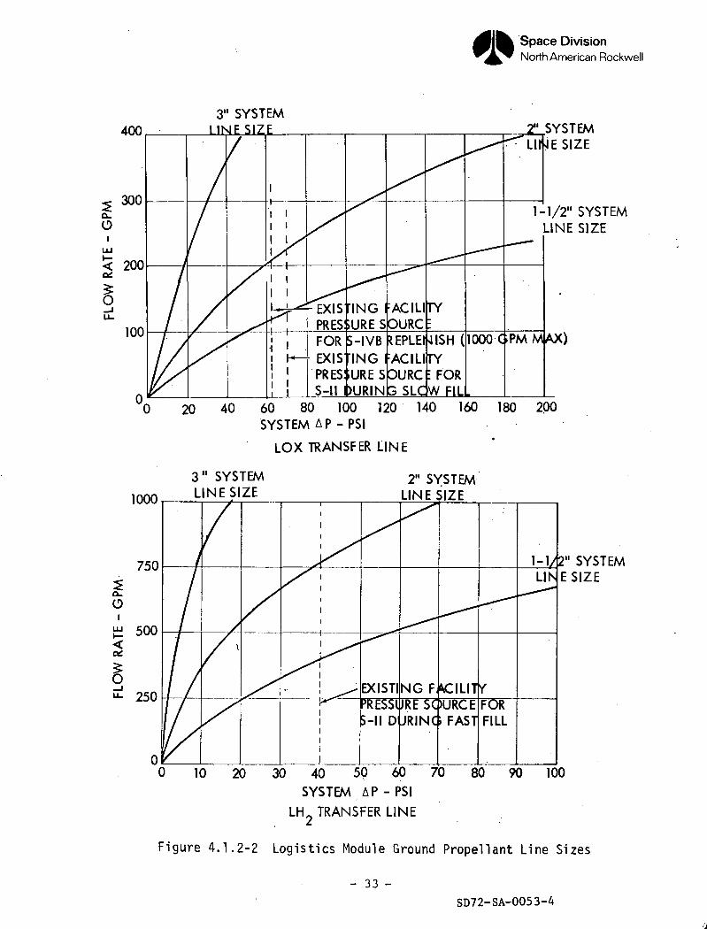
The timelines shown for the logistics module were developed utilizingSaturn S-II propellant loading comparisons. The flow rates were determinedby these timelines and the requirement for the serial loading concept. Atwo-inch nominal pipe diameter is of sufficient size to provide the selectedflow rates for both the liquid oxygen and hydrogen systems. Figure 4.1.2-2depicts various liquid oxygen and hydrogen flow rates in comparison withcalculated system pressure drops for three given line sizes.
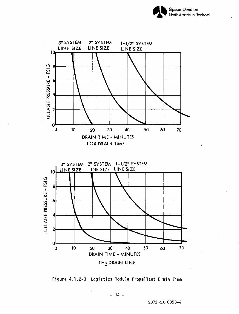
The data show that for the liquid oxygen system at the existing facilitytransfer line interface for either the Saturn S-II main fill line or theSaturn S-IVB replenish line, the pressure is adequate to provide the 200 gpmflow rate with a two-inch nominal diameter system line size. For the liquidhydrogen system at the existing facility transfer line interface for theSaturn main fill line, the pressure is adequate to provide the 550 gpm flowrate with a two-inch nominal diameter system line size. A critical factoralso considered in determining the line size was in limiting the tank draintime under emergency conditions to a safe level. The selected two-inch linesize is capable of draining the logistics tank in a time period comparablewith the shuttle orbiter and booster drain times under emergency conditionseither by pressure feed or gravity feed. Figure 4.1.2-3 depicts the draintime for three given line sizes under various ullage pressure conditions inthe liquid oxygen or hydrogen tanks.
The data show that the drain time required for the LOX tank, utilizing thetwo-inch line, would be approximately 31 minutes with a 4-psig ullage pressurefeed and 50 minutes with a gravity feed. The drain time required for the LH2tank, utilizing the two-inch line, would be approximately 29 minutes with a4-psig ullage pressure feed, and 170 minutes with a gravity feed. Thesedrain times are comparable with the present Saturn S-II and shuttle emergencydrain times.
The use of hydrogen slush as a propellant for the In-Space PropellantLogistics program is discussed in detail under Trade Studies, Volume III,Section 2.10. The results of this trade study indicate that the use ofhydrogen slush cannot be recommended at this time due to insufficient exper-imental data on its handling and operation. Therefore, hydrogen slush willnot be considered for use in the facility and GSE systems.
4.1.3 Additional and Modified Facilities
Various additions and modifications to Government facilities will have to beaccomplished in order to support the In-Space Propellant Logistics program.The facility additions .and modifications defined herein are described in gen-eral terms, and are intended to be a guide into a more detailed and extensivestudy e f for t . The government facilities under consideration for usage in theIn-Space Propellant Logistics program have not been exactly definitized, butthe following is a list of those facilities that can be modified to supporteach phase of the program.
- 32 -SD72-SA-0053-4
Space DivisionNorth American Rockwell
4003" SYSTEM
LINE SIZE
-IVBINGURE S
EURIN
SYSTEMLIl jESIZE
1-1/2" SYSTEMLINE SIZE
(1000 GPM MAX)
60 80 100 120 140SYSTEM AP - PSI
LOX TRANSFER LINE
1000
3" SYSTEMLINE SIZE
2" SYSTEMLINE SIZE
750
Q-o
<ce.
"- 250PRESSURE-II DURING
11 SYSTEMESIZE
10 20 70 80 90 10030 40 50 60SYSTEM A P - P S I
LH TRANSFER LINE
Figure 4.1.2-2 Logistics Module Ground Propellant Line Sizes
- 33 -SD72-SA-0053-4
Space DivisionNorth American Rockwell
10
3" SYSTEM 2" SYSTEM ].]/2" SYSTEMLINE SIZE LINE SIZE LINE SIZE
O
co
I4
LU
O< 2
10 20 30 . 40
DRAIN TIME -MINUTESLOX DRAIN TIME
50 60 70
O10
3" SYSTEM 2" SYSTEM 1-1/2" SYSTEMLINE SIZE LINE SIZE LINE SIZE
10 20 30 40 50DRAIN TIME -MINUTES
LH2 DRAIN LINE
60 70
Figure 4.1.2-3 Logistics Module Propellant Drain Time
- 34 -
SD72-SA-0053-4
Space DivisionNorth American Rockwell
a. KSC Saturn V Launch Complex
(To be utilized for installation, checkout, and propellant loading ofthe logistics module flight article and flight test article)
b. NASA Seal Beach, California Checkout Buildings
(To be utilized for post-manufacturing checkout of the logisticsmodule flight article, flight test article, and propellant transfertest article)
c. Mississippi S-II Static Firing Stand or Santa Susana PropellantTransfer Test Stand
(To be utilized for design and functional verification of the propellant,pneumatic, and electrical systems of the logistics module flight testarticle and the propellant transfer test article)
d. Houston Vacuum Chamber Complex and Huntsville Dynamic Test Stand
(To be utilized for thermal testing of the logistics module insulation,and dynamic structural testing of the module structure for the dynamic/thermal test article)
e. Seal Beach or Huntsville Static Structural Test Facility
(To be utilized for hydrostatic structural testing of the logisticstank structural test article)
f. Landing and Safing Facility
(To be utilized for post-launch safing, checkout, and refurbishment ofthe logistics module flight article and flight test article)
The main study emphasis has been directed at the KSC facilities and equipmentutilized to support propellant storage and transfer operations, while stillreviewing to a lesser degree, that equipment and facilities utilized toreceive, check out, handle, service, launch, safe, and refurbish the logisticsmodule flight article, and to test the various logistics module test articles.Table 4.1.3-1 compares the existing KSC launch facility storage capacity,'refill rates, and transfer rates with the propellant utilization requirements.The table also includes the anticipated additions and modifications requiredto meet the propellant requirements.
As can be seen from the table, there are no modifications anticipated for thepropellant storage facility. The liquid oxygen storage capacity is 8.6million pounds per launch pad, with a maximum refill rate of 1.2 millionpounds per day. The liquid oxygen utilization for one launch will beapproximately 4.3 million pounds. This would allow for more than adequatereserve for each launch. and with the present refill rate, could load thestorage tank to the full condition in a 3-1/2-day period. (This exceedsother constraints mentioned later, which limit the requirement to one launchevery seven days from one launch pad.) The liquid hydrogen storage capability
- 35 -SD72-SA-0053-4
Space DivisionNorth American Rockwell
is .51 million pounds per launch pad, with a maximum refill rate of .08million pounds per day. The liquid hydrogen utilization for one launch willbe approximately .18 million pounds. This would allow for more than adequatereserve for each launch, and with the present refill rate, could load thestorage tank to the full condition in a 2-1/2-day period. Thus, a vehiclecould be launched from one pad every 2-1/2 days.
Table 4.1,3-1
Additions and Modifications to KSC Propellant Facilities
EquipmentExisting
Capabilities
NewPropellantUsage
Additions/Modifications
LOX storage
LH2 storage
LOX transfer
8.6 mil Ib/pad1.2 mil Ib refill/day
.51 mil Ib/pad
.08 mil Ib/refill/day
10,000 gpm
4.3 mil Ib/launch
.18-mil Ib/launch
1700 gpm
LH2 transfer 10,000 gpm 10,550 gpm
None
None
Add flow controlcomplex, transferlines, and inter-faces .Adjust pump gov-ernors to providelower flow rate
Add flow controlcomplex, transferlines, and inter-faces .Increase storagetank pressurefrom 60 psig to65/70 psig.
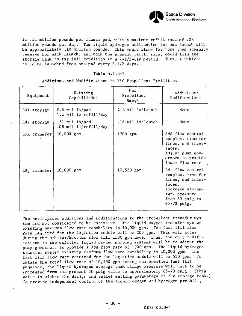
The anticipated additions and modifications to the propellant transfer sys-tem are not considered to be extensive. The liquid oxygen transfer systemexisting maximum flow rate capability is 10,000 gpm. The fast fill flowrate required for the logistics module will be 200 gpm. This will occurduring the orbiter/booster slow fill 1500 gpm mode. Thus, the only modifi-cations to the existing liquid oxygen pumping systems will be to adjust thepump governers to provide a low flow rate of 1700 gpm. The liquid hydrogentransfer system existing maximum flow rate capability is 10,000 gpm. Thefast fill flow rate required for the logistics module will be 550 gpm. Toobtain the total flow rate of 10,550 gpm during the combined fast fillsequence, the liquid hydrogen storage tank ullage pressure will have to beincreased from the present 60 psig value to approximately 65-70 psig. (Thisvalue is within the design and relief setting parameters of the storage tank.)To provide independent control of the liquid oxygen and hydrogen prechill,
- 36 -SD72-0053-4
Space DivisionNorth American Rockwell
main fill, topping, and drain functions for the logistics module, a flow con-trol unit for each system will be required. These two units will be similarto the orbiter/booster control units in regard to system concept (i.e., sys-tem configuration, valving, and operational function), but will be smaller inoverall size (two-inch nominal line size). Propellant interfaces for theflow control units will have to be provided in the main transfer lines up-stream of the orbiter/booster control units on the launch tower. Figure4.1.3-1 depicts in block diagram form, the propellant transfer configurationfrom the storage tank to the orbiter/booster interface on the launch tower.
Other KSC facility modifications and additions to be considered are in thetransfer aisle, low bay, high bay, and launch control center areas. Someof the functions of the transfer aisle area will be to provide receiving,unpackaging, pre-installation inspection, installation, and interface veri-fication capabilities for the logistics module. One of the functions of thelow bay area will be to provide premate checkout capabilities for the logisticsmodule. Some of the functions of the high bay area will be to provide stack-ing, prelaunch checkout, and launch readiness capabilities for the logisticsmodule. Additional facility equipment required in these three areas willconsist mainly of personnel access platforms, console support platforms, trans-fer dolly center support structure, and fluid and electrical distribution'system interfaces. The existing hoisting equipment is adequate for alllogistics module lifting functions. Modifications in the launch control cen-ter will be required to provide pneumatic and electrical control for thevarious logistics module servicing, propellant loading, and launch countdownfunctions. This will entail additions and/or modifications to various controlconsole equipment (e.g., indications, communications, switch controls, etc.).
The requirement for the number of launch pads necessary to support the var-ious space traffic program levels, is considered to be of significant import-ance. The number of launch pads required to support any space program willdepend to a large degree on the number of launches per month for that pro-gram, the launch pad turnaround time, the shuttle turnaround time, theshuttle fleet size, and various other constraints. For the purpose of thisstudy, only the number of launches per month and the shuttle and launch padturnaround times will be considered. Figure 4.1.3-2 reflects the number oflaunch pads required versus various efficiency levels for the number oflaunches per month for each space traffic program level.
As can be seen from the graph, program levels A, B, and C can be supportedby one launch pad, program level D (RNS) can be supported by two launch pads,program level E (RNS) can be supported by two or three launch pads dependingon the efficiency level, program level D (CIS) can be supported by threelaunch pads, and program level E (CIS) can be supported by three or fourlaunch pads depending on the level of efficiency. The 100-percent efficiencyline was based upon a shuttle and launch pad turnaround of seven days. Thelaunches per month for program levels A, B, and C were determined by takingthe flight schedule for the peak usage years and distributing those flightsevenly over the entire year. The launches per month for progrm levels D andE were determined by compacting the total CIS/RNS lunar flights into two80-day refill periods, and distributing the rest of the flights (also duringpeak usage years) evenly over the entire year. Only non-polar orbital
- 37 -
SD72-SA-0053-4
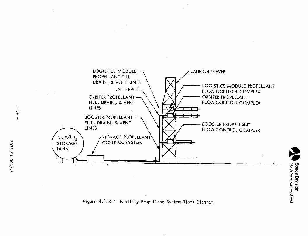
Space
Div
isio
nN
orth A
merican R
ockwell(O(0
ooocaE=
ooc(OO)
a.
2CL,
OCOa>
- 3
8 -
SD72-SA
-0053-4
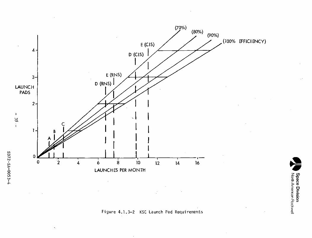
Space
Div
isio
nN
orth A
merican R
ockwell
LU
yu_tooo
t/1•(->cca3C
T0>
-o03Q
-OCrd_JOCO
<-0)O)
SD72-SA
-0053-4
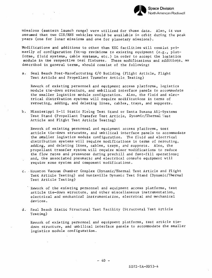
Space DivisionNorth American Rockwell
missions (eastern launch range) were utilized for these data. Also, it wasassumed that two CIS/RNS vehicles would be available in orbit during the peakyears (one for lunar missions and one for planetary missions).
Modifications and additions to other than KSC facilities will consist pri-marily of configuration fit-up revisions to existing equipment (e.g., plat-forms, fluid systems, cable systems, etc.) in order to accept the logisticsmodule in the respective test fixtures. These modifications and additions, asdescribed in general terms, should consist of the following:
a. Seal Beach Post-Manufacturing C/0 Building (Flight Article, FlightTest Article and Propellant Transfer Article. Testing)
Rework of existing personnel and equipment access platforms, logisticsmodule tie-down structure, and umbilical interface panels to accommodatethe smaller logistics module configuration. Also, the fluid and elec-trical distribution systems will require modifications in terms ofrerouting, adding, and deleting lines, cables,, trays, and supports.
b. Mississippi S-II Static Firing Test Stand or Santa Susana All-SystemsTest Stand (Propellant Transfer Test Article, Dynamic/Thermal TestArticle and Flight Test Article Testing)
Rework of existing personnel and equipment access platforms, testarticle tie-down strucutre, and umbilical interface panels to accommodatethe SEialler logistics module configuration. The fluid and electricaldistribution systems will require modifications in terms of rerouting,adding, and deleting lines, cables, trays, and supports. Also, thepropellant transfer system will require minor modifications to reducethe flow rates and pressures during prechill and fast-fill operations;and, the associated pneumatic and electrical console equipment willrequire some system and component modifications.
c. Houston Vacuum Chamber Complex (Dynamic/Thermal Test Article and FlightTest Article Testing) and Huntsville Dynamic Test Stand (Dynamic/ThermalTest Article Testing)
Rework of the existing personnel and equipment access platforms, testarticle tie-down structure, and other miscellaneous instrumentation,electrical and mechanical instrumentation, electrical and mechanicaldevices.
d. Seal Beach Static Structural Test Facility (Structural Test ArticleTesting)
Rework of existing personnel and equipment platforms, test article tie-down structure, and umbilical interface panels to accommodate the smallerlogistics module configuration.
- 40 -
SD72-SA-0053-4
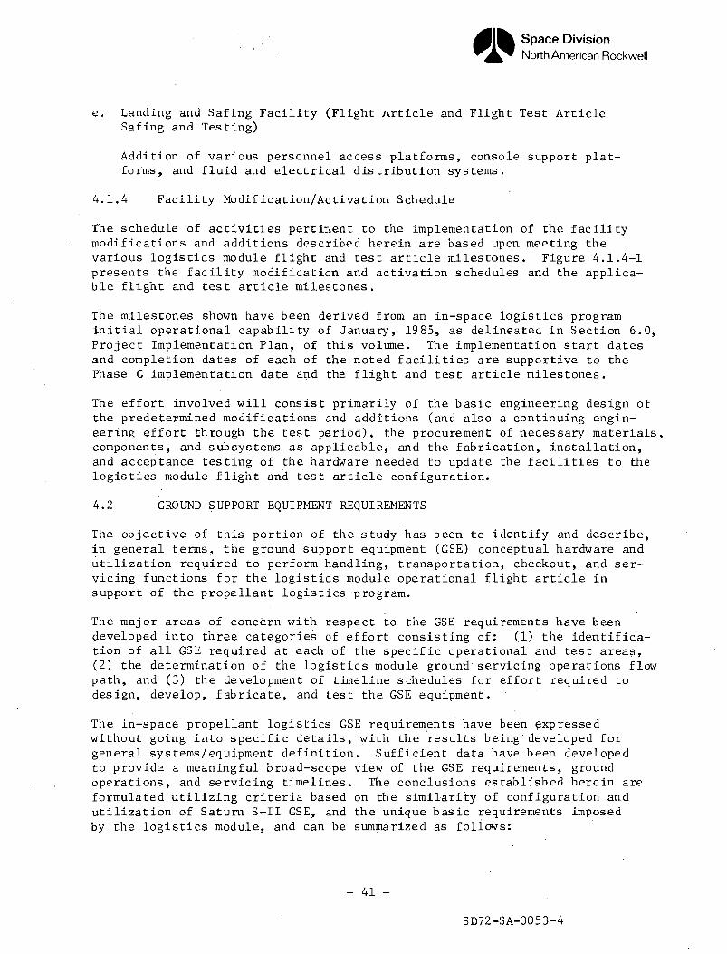
Space DivisionNorth American Rockwell
e. Landing and Safing Facility (Flight Article and Flight Test ArticleSafing and Testing)
Addition of various personnel access platforms, console support plat-forms, and fluid and electrical distribution systems.
4.1.4 Facility Modification/Activation Schedule
The schedule of activities pertinent to the implementation of the facilitymodifications and additions described herein are based upon meeting thevarious logistics module flight and test article milestones. Figure 4.1.4-1presents the facility modification and activation schedules and the applica-ble flight and test article milestones.
The milestones shown have been derived from an in-space logistics programinitial operational capability of January, 1985, as delineated in Section 6.0,Project Implementation Plan, of this volume. The implementation start datesand completion dates of each of the noted facilities are supportive to thePhase C implementation date and the flight and test article milestones.
The effort involved will consist primarily of the basic engineering design ofthe predetermined modifications and additions (and also a continuing engin-eering effort through the test period), the procurement of necessary materials,components, and subsystems as applicable, and the fabrication, installation,and acceptance testing of the hardware needed to update the facilities to thelogistics module flight and test article configuration.
4.2 GROUND SUPPORT EQUIPMENT REQUIREMENTS
The objective of this portion of the study has been to identify and describe,in general terms, the ground support equipment (GSE) conceptual hardware andutilization required to perform handling, transportation, checkout, and ser-vicing functions for the logistics module operational flight article insupport of the propellant logistics program.
The major areas of concern with respect to the GSE requirements have beendeveloped into three categories of effort consisting of: (1) the identifica-tion of all GSE required at each of the specific operational and test areas,(2) the determination of the logistics module ground"servicing operations flowpath, and (3) the development of timeline schedules for effort required todesign, develop, fabricate, and test, the GSE equipment.
The in-space propellant logistics GSE requirements have been expressedwithout going into specific details, with the results being'developed forgeneral systems/equipment definition. Sufficient data have been developedto provide a meaningful broad-scope view of the GSE requirements, groundoperations, and servicing timelines. The conclusions established herein areformulated utilizing criteria based on the similarity of configuration andutilization of Saturn S-II GSE, and the unique basic requirements imposedby the logistics module, and can be summarized as follows:
- 41 -
SD72-SA-0053-4
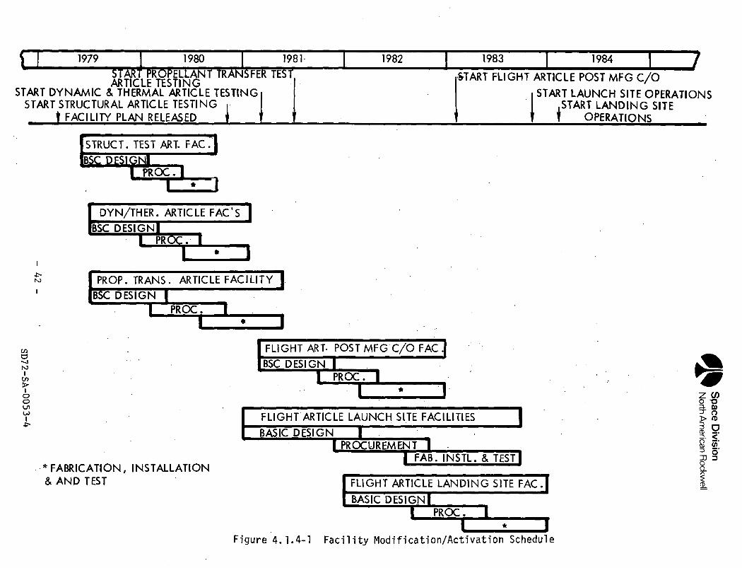
oo*.
Z"^
M^H
30s
CO
00
o»•••••
CN
OO
Os
^^^
1-1-
OO
CK8Ov
CS
|S.
1O;_
Oi-UJ J
3.0
1""
^°?zo
tzo
U_
OO
Q
,_
5 xZ
<H-
u<
25
00
Z
°-
2?i°LU
—
1 Ji
— '
h- o
oy 3 -^
a: >-
<
oo
^I—XOju_1—%1_rruno±j^~O£
fc
E
ooo
-7
%
*2
la "—^ ^
-o
ART PROPELLANlTICLE TESTINGHERMAL ARTICLEARTICLE TESTIN'
LAN RELEASED
^<
Q-
•*§
£
^"
^M n
<i^
z^2
:*w
O
O^
' -^
Q 1
-.
a;
5^
<t^
^_.^_ _,^A
^
North
Am
erica
n R
ockw
ell
^^^^
ta^_
k_ "'s
U
"o•5
a>
i • i ^
l^^ ^*u.
P\ *
u0u_ ^~
5•^
.I-
U
00
/Sn
u
w f>x
a. _ g:
fe z
J^ o
H- </>LZ
LU
m
n
S>-
^ 2~J
- m
mm
mm
m
^T
JL
•••
ooLU
P_1
I)
^ Ll_
n i
1—
.
OO
X'
UzZ3<LU
_l
yi—<f—XO_l
U-
n
^
o1 —
LU
O
OO
O
1 —
4.LU
_
*
Et—
00
O
«rf
O
P"
£
• j
z
5—
J -^
.—
.*—
O
* ••* +
-><
/) -?
t J
o
-_ /
^X
>
Jz
<
0
<~
-" §f
="_
ffi
LU
—
°-
.0
<
-j Z
^
l_ u
- U
f
(0
Z J
i=
-
-°
UJ
^
00
14-
-<
<
LU
-r-
a
i- Q
•§"
o N
t
-8 5 <
.?g:
« —
r
^
O
z ,«
0i/l i—
UJ
I
Qrt
^T
•
y r
LA
v*.
"I
*>
•<m
<ui-3cn
^5
^ '
£¥
"• r
n
n ^
* ^u
"- 1 M
y • -J
?2 „• d
rj 5 8
i
S C
J S
»
•-* d
<
8
. -
£
7
^^
ci
e^
Z
^Z
-J
•
"
g z
g
S o
-1
| o
2. 2
J <
a .
^ ta
• '
"C
«3
z Q
g
o z
= Q
S
2 y
o
^g
^
la
"£
, $
®a
u "~^
QS
z<
*f,^•a
- 4
2 -
SD
72-SA
-0053-4oo
Space DivisionNorth American Rockwell
a. The GSE requirements have been definitized in general terms, and theequipment and systems can be designed within the present state-of-the-art knowledge and experience.
b. The ground operations .flow and prelaunch/post-landing timelines have beendeveloped, and they meet the overall shuttle program requirements with noforeseeable problems.
c. The GSE fabrication and activation implementation schedules are supportiveto the in-space logistics programmed initial operational capability ofJanuary, 1985.
4.2.1 Equipment Identification
The mechanical and electrical GSE identified herein will be utilized tosupport the ground operation functions for the propellant logistics modulein the following operational and test areas: (1) post-manufacturing check-out and acceptance testing; (2) transportation operations; (3) prematecheckout operations; (A) installation and mating verification; (5) prelaunchsystems readiness operations; (6) launch preparation and launch operations;and (7) post-flight safing and maintenance operations. The GSE will bedesigned to satisfy the specific operational and test area requirements forthe propellant logistics module. Table 4.2.1-1 presents the conceptualidentification (in generalized groupings) of the necessary GSE required tosupport the various ground operational functions for the logistics module atthe specific test area.
The equipment is categorized into four classes of GSE: (1) checkout (veri-fies flight article systems, provides controls, distributes electrical andfluid signals, and supplies electrical power); (2) auciliary (performsspecial functions and fulfills special operational requirements); (3) ser-vicing (supplies, distributes, conditions, and disposes fluids for theflight article systems; and (4) handling (supports and handles the flightarticle, its assemblies, subassemblies and components).
The determination of whether existing Saturn, Apollo, or Government GSEcould be utilized to perform some of the operational functions, has not beenachieved in this study because the logistics module performance capabilitiesand interfaces have nbt been defined in sufficient detail. Therefore, onlythe requirement for a particular GSE item or system of items has been identi-fied.
4.2.2 Ground Servicing Operations
The ground servicing operations required to support the propellant logisticsmodule flight article: shall, include the flow path, from the time of deliveryfrom manufacturing at the start of its operational life, through post-landingoperations and recycling. Figure 4.2.2-1 depicts the representative logisticsmodule flight article flow path, and the figurative GSE requirements.
- 43 -
SD72-SA-0053-4
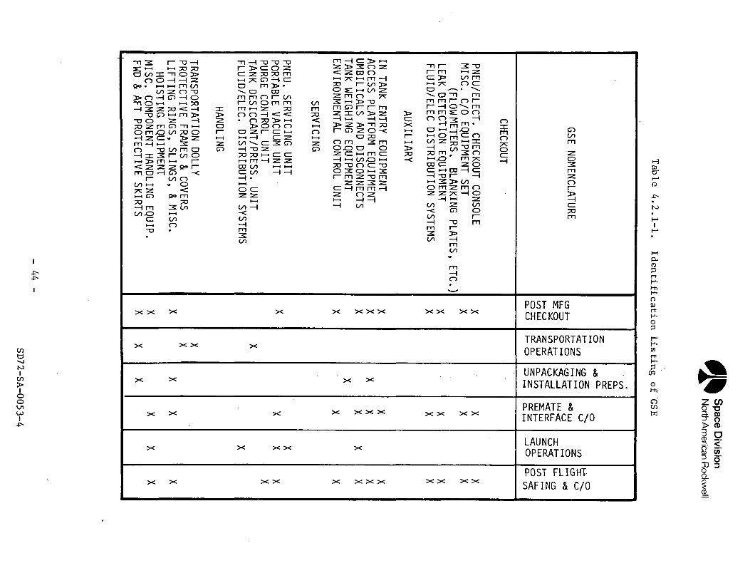
Space
Divisio
nN
orth A
merican R
ockwell
Tab
le 4
.2.1
-1.
Ide
ntific
atio
n
Listin
g
of 'G
SE
GSE NOMENCLATURE
CHECKOUT
PNEU/ELECT. CHECKOUT
CONSOLEMISC.
C/0 EQUIPMENT SET
(FLOW METERS, BLANKING
PLATES, ETC.)
LEAK DETECTION
EQUIPMENTFLUID/ELEC
DISTRIBUTION SYSTEMS
AUXILIARY
IN TANK ENTRY
EQUIPMENTACCESS
PLATFORM EQUIPMENT
UMBILICALS AND
DISCONNECTSTANK
WEIGHING EQUIPMENT
ENVIRONMENTAL CONTROL
UNIT
SERVICING
PNEU. SERVICING UNIT
PORTABLE VACUUM
UNITPURGE
CONTROL UNIT
TANK DESICCANT/PRESS.
UNITFLUID/ELEC.
DISTRIBUTION SYSTEMS
HANDLING
TRANSPORTATION DOLLY
PROTECTIVE FRAMES
& COVERSLIFTING
RINGS, SLINGS, &
MISC.HOISTING
EQUIPMENTMISC. COMPONENT
HANDLING EQUIP.
FWD & AFT PROTECTIVE
SKIRTS
cat-si o1— 0
to uj0 1C
Q- CJ
XXXXXXXXXXXX
0t— I1—•=C
ooI- z:OL 0
Q. I—
t/5 <£
< UJ
a: 0.
1- 0
XXXX
• ooO-UJ
-a|
z °
3 fc
^5
o
Q. {
= 5XXXX
oo08 ii iUJ <;
f r
UJ i
*-~XXXXXXXXXXX
00
oHH
re H-
c_> y fV*
=> Ll-l<: o-_J 0
XXXXX
•x: ^
<L3 CJ
!H
u- CJ3
| —
OO n
O ej;
XXXXXXXXXXXX
- 4
4 -
SD72-SA
-0053-4
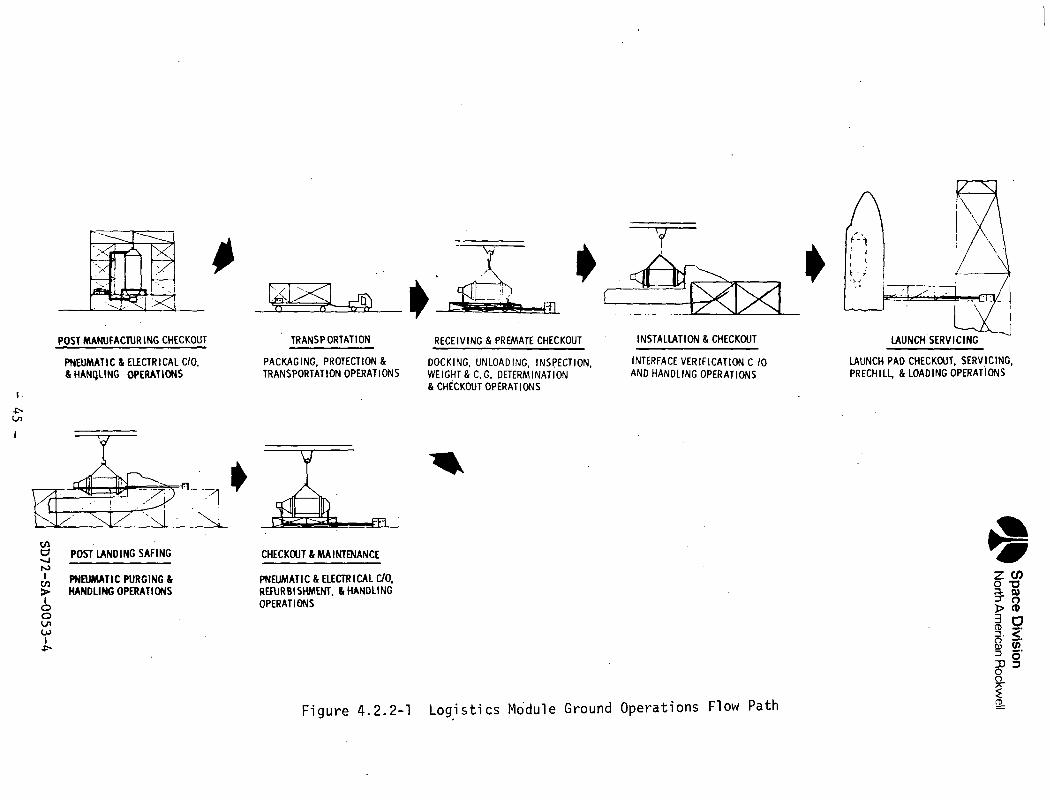
Space
Div
isio
nN
orth A
merican
Rockw
ell
oB O
< 5
o- t—
o'o
(OQ
-
O000)Q.
O-oc3oCDO)
T3Oo•r-
-Pto•r—0
>OCM•3-<DS
-
CD
°2
zcz </* o
Oat
SD72-SA
-0053-4
Space DivisionNorth American Rockwell
The post-manufacturing acceptance checkout operations will be accomplishedin a vertical position on a facility base mount fixture. The logistics mod-ule will be positioned into the checkout station on the mount fixture, util-izing facility cranes and GSE hoisting and handling equipment. Access willbe provided by facility work platforms and GSE supplemental access platforms.Pneumatic and electrical checkout GSE will perform the acceptance checkoutfunctions. Following post manufacturing checkout, the logistics module willbe positioned on the GSE transportation dolly via the same lifting equipment,and made ready for transport to KSC by sea or air. The liquid oxygen andhydrogen tanks will be maintained in a clean condition and protected bymeans of a portable desiccant or pressurization unit. The entire logisticsmodule will be protected with appropriate packaging, and GSE frame and covertransportation equipment.
Upon delivery to KSC, the logistics module will be transported to the VerticalAssembly Building (VAB) transfer aisle area for unpackaging, inspection,weight/c.g. determination, and preparation for premate checkout and installa-tion into the orbiter cargo bay. The logistics module will be positionedinto the low bay checkout cell. Access will be provided by facility workplatforms and GSE supplemental access platforms. Pneumatic and electricalcheckout GSE will conduct various integrated systems checkout tests. Uponcompletion of premate checkout the logistics module will be removed to thetransfer aisle area and positioned into the orbiter cargo bay, utilizingfacility cranes and GSE hoisting and handling equipment, and then mated tothe orbiter interfaces. The logistics module-to-orbiter interface verifica-tion tests will be performed in preparation for launch. Subsequent to theseprelaunch checkout operations, the orbiter will be stacked and positioned onthe launch pad. The logistics module GSE servicing pneumatic equipment willthen be activated to supply, distribute, condition, and dispose fluids forthe logistics module systems, in support of launch propellant loading andservicing countdown operations.
Upon completion of orbiter landing and cooldown, the logistics module willbe inerted and safed, utilizing a GSE pneumatic purge unit. The module willthen be removed from the orbiter cargo bay and transferred to the mainten-ance/refurbishment area and installed in the checkout stand. GSE (commonto other checkout sites) will be provided at the maintenance area, to pro-vide for logistics module subsystem functional diagnostic checkout, flightanalysis, maintenance, handling, transportation, and complete visual inspec-tion functions. Periodic programmed maintenance tasks will include removalreplacement, repair, calibration, adjustment, checkout, test, and inspectionto the subassembly or detail part level. Upon completion of post-landingoperations, the logistics module will be recycled back to launch operations.
In addition to the aforementioned GSE, equipment will be provided for spec-ial logistics module field operations, such as tank entry and storage func-tions. Tank entry will require GSE internal access stands, hoisting equip-ment, work platforms, ladders, environmental enclosures and tank airconditioning equipment.
The logistics module and shuttle preflight operations, in accordance with theFigure 4.2.2-2 activity timeline phasing, will primarily consist of thefollowing:
- 46 -
SD72-SA-0053-4
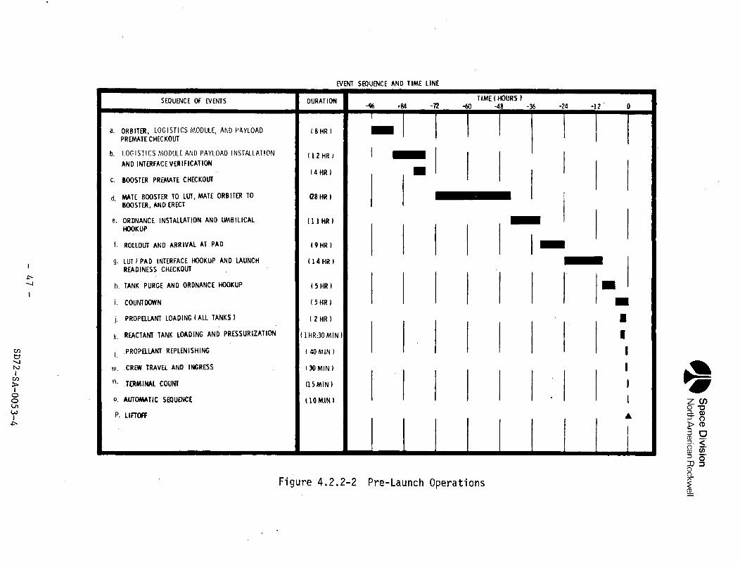
Space
Divisio
nN
orth A
merican R
ockwell
UJ
ZUJ
0zUJ
O5sa
CM
(/»
atoUJ
h^
Pi
S
1<
.=3oto&aUJ
O1sl/l 10£ZOO
0^>_*x^**OGISTICS MODULEECKOUT
— i
ZoK
UJ
t—t—
<
CD
J5X
QC
O Q
_
"'
MIoe ^X
~2:oh—^-j
*^
zQO
MODULE AND PAYL
WE VERIFICATION
REMATE CHECKOUT
LTl
U.
O.
S£ S
«
i-- fc
a
!2 -
KO
O
Q
3 5 i
.C!
O .1_ -
i •*
OO
*"*
~
S
<*~
5B
5
°
TER TO LUT, MATEND ERECT
INSTALLATION AN
S *
UJ
§B i%uj U
f g
^
•< o
at o
3«
oi
•o <" 1a
t
a,1atat^
ROLLOUT
I
•1z
»
35
%<=>
nz
§<
Z
NTERFACE HOOKUPCHECKOUT
;E AND ORDNANCE
t/i 2
IS
£—
Q
*:
13 1
en
-C
^
'
Z
_
_
« ^ s i
z 5
s
r ~
~
-
-
§Nl
=3
in-
ai/*
QC
*£
Q-
<
Q
~j
T-
UJ
< i 1 |
lili^
Mz
S 1
S 5
§
f^f
^
^5
rf j
U
1 1 1 1 i 1 1 1o
a.
oe
Q.
Oh
-^
3
.- •-
~
_•
£
c
o
°-
nsS-
O)
Q-
OO(OS-
Q_
CM
CM•
CMOJ
CD
- 4
7 -
SD
72-SA
-0053-4
Space DivisionNorth American Rockwell
a. Orbiter, Logistics Module, and Payload Premate Checkout - Checkout per-formed during the premate period provides the basic confidence that theorbiter and logistics module subsystems have withstood the previousflight and are capable of supporting another mission.
b. Logistics Module and Payload Installation and Interface Verification -The orbiter will be moved to the mating area and the cargo bay set upfor receipt of the propellant module and payload modules. Holdingequipment will then be utilized to install these modules in the cargobay. Next, interfaces will be connected and verified by performingcontinuity and pressure tests.
c. Booster Premate Checkout - Similar to Item "a".
d. Mate Booster to LUT, Mate Orbiter to Booster and Stack - The booster willbe moved to the mating area and all separation and mating mechanisms andsurfaces are inspected and readied for mating. The booster will then belifted to the vertical position and lowered onto the mobile launcher, andhold-down mechanisms attached and secured. All booster electrical,hydraulic, pneumatic and cryogenic launcher interfaces are connected andverified. Next, the orbiter will be lifted to a vertical position andmated to the booster. All orbiter electrical, hydraulic, pneumatic, andcryogenic launcher intei-faces are connected and verified.
e. Ordnance Installation and Umbilical Hookup - All ordnance will beinstalled and verified and umbilicals connected and verified.
f. Rollout and Arrival at Pad - The space shuttle mobile launcher will betransported by the transporter from the VAB to the launch pad. The padwill have been previously prepared for the arrival of the shuttle system.
g. LUT/Pad Interface Hookup and Launch Readiness Checkout - The pad-to-mobile launcher electrical and fluid interfaces will be connected andverified. Warning and monitoring systems interfaces will be verified bycondition simulations.
h. Tank Purge and Ordnance Hookup - After the connection of ordnance con-nectors, liquid hydrogen tanks and lines will be conditioned to ahydrogen atmosphere. Rigid pad and vehicle access controls are now ineffect.
i. Countdown - Start of five-hour countdown will be initiated.
j. Propellant Loading (All Tanks) - Chilldown of all transfer lines andtankage, venting, transfer, replenishment, and termination are accomp-lished by an automated system. After chilldown, simultaneous loadingof all liquid oxygen and hydrogen into the booster, orbiter, and payload(if required) will begin. The logistics module loading will be initiatedat the same time; however, liquid oxygen loading will precede liquidhydrogen loading in a serial loading mode.
- 48 -
SD72-SA-0053-4
Space DivisionNorth American Rockwell
k. Reactant Tank Loading and Pressurization - Next, the reactant tanks willbe loaded and pressurized.
1. Propellant Replenishing - The topping mode (flow rate) of the propellantloading control system will be used to replenish propellants lost inboil-off.
m. Crew Travel and Ingress - The launch pad facility will have a rapid-liftelevator within the service tower to transport four crew members, twoload masters, ten passengers, and the closeout crew to the boarding plat-form access arms.
n. Terminal Count - Next, the terminal countdown which includes a verifica-tion that all systems are configured for launch will be performed.
o. Automatic Sequence - During the final ten minutes prior to launch, thecountdown will progress automatically.
p. Lif toff - The space shuttle will achieve a free l if toff and rise from thepad.
The logistics module and orbiter post-landing operations, in accordance withthe Figure 4.2.2-3 activity timeline phasing, will primarily consist of thefollowing:
a. Landing Complete (T = 0) - The orbiter completes its mission and returnsto the launch landing site and lands. The flight crew immediately ini-tiates on-board safing, securing, and shutdown procedures.
b. Tow Orbiter to Safing Area - The orbiter will be towed (or taxied) tothe safing area.
c. Secure Orbiter and Remove Flight Personnel and Flight Data - Upon reachingthe safing area, ground servicing system hookup and installation willbegin concurrently with flight crew and passenger egress. At the sametime, the pilot log and recorded flight data will be obtained and post-flight data analysis initiated.
d. Perform Post-Flight Safing - During post-flight safing, orbiter andlogistics module liquid propellant residuals will be drained and pro-pellant and reactant tanks will be vented and inerted. The vehicleinterstitial spaces will be purged to remove heat from the structure;and all ordnance will be safed or removed.
e. Tow Orbiter to Hangar Area - When the safing and cooldown requirementshave been met, the vehicle will be towed to the maintenance area forhangar operations.
f. Prepare for Hangar Operations - Upon arrival at the maintenance hangar,the orbiter will be positioned, secured, placed on jacks, raised andleveled. Normal servicing will then commence as well as additional dataanalysis on mission anomalies.
- 49 -
SD72-SA-0053-4
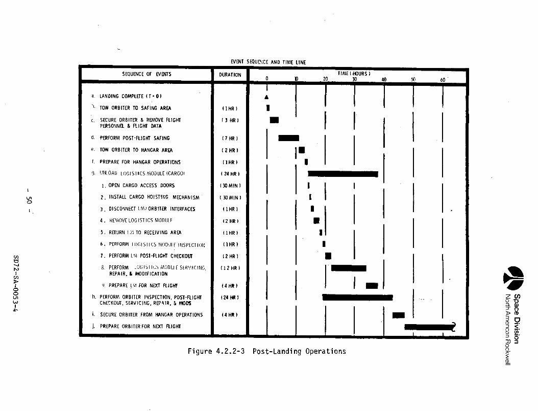
Space D
ivisionN
orth A
merican
Rockw
ell
zUJ
QZ*t
Ofi'=3
St—s IO
cc9s
UJ
O
^t—ceot/l
a0UJ
Osofcrt
»
,'
1.
m m
"• ••
1i ..
—
— •
— .
§= §= xx
xx
ii
ss
i-
is
«i*
-»
rr
»
r"
"*
VJ
^H
<^
&^
^^
£X
J1
""
''
^*
s*
»-
t ^
"3
5—
' —
-^
"-
^
o"
i a
G
5 5
2<
y
Q-
o
zz
^2
—
^ rr*
to
js
Lu
fc—
os
gS
a
s
s
- a
^
. o
£
.,
—
<;
2<
£E
5u
j<
^o
3
o"
1"-
0".
. 1 5
, 1 i
1 5
1 1
g §
1 I
S ll
5 §1
Mi Is 5
s * I s i §
5;
§ s ! <ss §
g-.
^u
.c
e^
.f
ez
QC
S0
xc
>'
Ou
j^
5;
v,
u.
^o
uj
i^
«0
_
z"
<o
S0
0O
oQ
'o
0°
o:
"S
eK
i^
ex
^o
^^
o-
o-
sr
Bs
^^
;°
-t
^t
-l
/1
<J
^0
05
£—
ji
^
— «
Se
e-
rt
iQ
^^
oS
i-
'^
ss
-r
gS
«i
°|
si
s^
sg
'S
iS
SS
S<
2s
5Q
0-
=S
£°
cf
oO
—
Q
^a
^^
o^
^^
go
zS
oo
eo
eS
1^
-1
— '
c,cu
j
re"
J=
u
-o'
d
— '
=r>
•=
'
1X«T
l/»
085Q.
t-o
£ooc
—<
tio1 1o
S5
£
2ac
uj!=
m
or o
° U
J
a:
<ID
a.
CJ
l*J
OO
C
u
030)
O.
OCD
cinOQ.
roCMQJi-CT>
- 50
-
SD72-SA
-0053-4
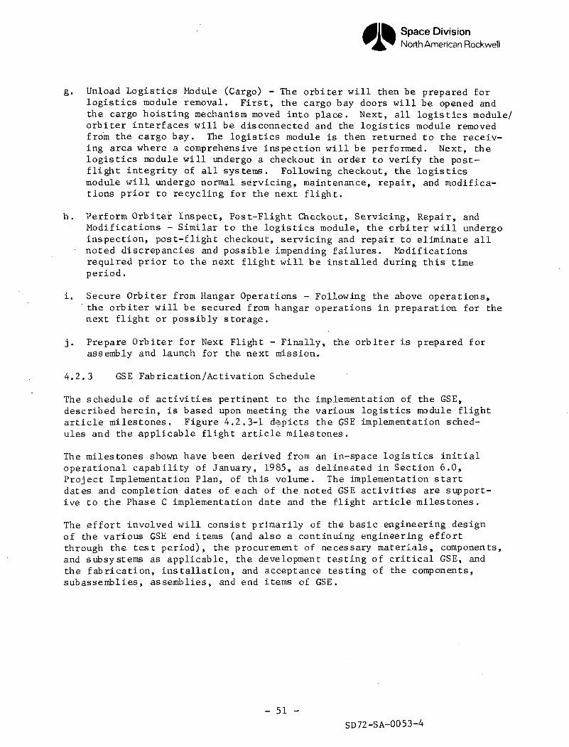
Space DivisionNorth American Rockwell
g. Unload Logistics Module (Cargo) - The orbiter will then be prepared forlogistics module removal. First, the cargo bay doors will be opened andthe cargo hoisting mechanism moved into place. Next, all logistics module/orbiter interfaces will be disconnected and the logistics module removedfrom the cargo bay. The logistics module is then returned to the receiv-ing area where a comprehensive inspection will be performed. Next, thelogistics module will undergo a checkout in order to verify the post-flight integrity of all systems. Following checkout, the logisticsmodule will undergo normal servicing, maintenance, repair, and modifica-tions prior to recycling for the next flight.
h. Perform Orbiter Inspect, Post-Flight Checkout, Servicing, Repair, andModifications - Similar to the logistics module, the crbiter will undergoinspection, post-flight checkout, servicing and repair to eliminate allnoted discrepancies and possible impending failures. Modificationsrequired prior to the next flight will be installed during this timeperiod.
i. Secure Orbiter from Hangar Operations - Following the above operations,the orbiter will be secured from hangar operations in preparation for thenext flight or possibly storage.
j. Prepare Orbiter for Next Flight - Finally, the orbiter is prepared forassembly and launch for the next mission.
4 .2 .3 GSE Fabrication/Activation Schedule
The schedule of activities pertinent to the implementation of the GSE,described herein, is based upon meeting the various logistics module flightarticle milestones. Figure 4.2.3-1 depicts the GSE implementation sched-ules and the applicable flight article milestones.
The milestones shown have been derived from an in-space logistics initialoperational capability of January, 1985, as delineated in Section 6.0,Project Implementation Plan, of this volume. The implementation startdates and completion dates of each of the noted GSE activities are support-ive to the Phase C implementation date and the flight article milestones.
The effor t involved will consist primarily of the basic engineering designof the various GSE end items (and also a continuing engineering effor tthrough the test period), the procurement of necessary materials, components,and subsystems as applicable, the development testing of critical GSE, andthe fabrication, installation, and acceptance testing of the components,subassemblies, assemblies, and end items of GSE.
- 51 -SD72-SA-0053-4
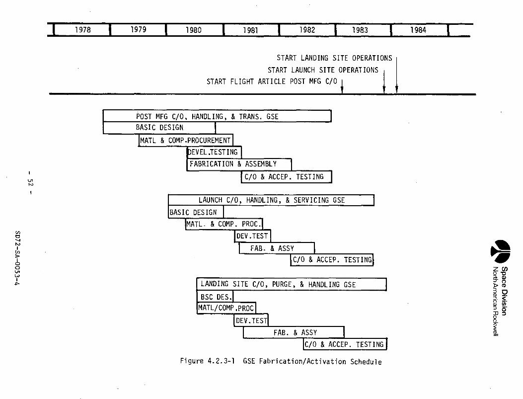
Space D
ivisionN
orth A
merica
n R
ockwell
•Mi
*s-C
Oo>r-*
MM
n^
< t
CO
Cn
^«-
•Mi
OsJ
CO
cn
•mCO
cn•~
^^f
oCO
cn
^M
i
cnp*cn
•••
CO
r^cn
^M
00z
^0
*£
oo
i oL^
i t
LU
£a.
5o 2LU
£
ol
_t ° ~
~^
^
LU °
CD
IH
<->
-^^
^^
^
°°
CD
i =
3E
3 - Ji?
^
fc 2
g
? fe
1/1 <
dr^
*— <1/1
fe«tfeCD
H—
11LU
1—o;
<cOO
••••
LUooCD
oo<c.o;
t—oa„C
D
i— i
_l
O<c»>
oCJ
CD
LUr
-^ioooQ.
>-
^1
CO
5oooo<cf^
oa
CD
1
^
z
z p 2
LU
^
P
— s t^ s
o; ~
"
3 d g
§
S £
0.
Q ^
—CDZI—
*h-ooLU1r™C
L.LiJ
OCJ
o3
0e>•H
W
Z
Cu
CD
2£
^— '
5^
i— i
Ooo
<->LUQ
oB
«
P!
I~H
"00
<t
«c 2:
co •—
*
•
[ ! |
ooCD
CDZi—
iC
Jh—
1
C£
LUOO
o3
«t
CD
*-H_1
Q•ZL
0o3:
CJ^^><c_
l
FCDi — iooLU1—Q
-LUCJ
y4»
oS
o"K^
^ °oooo<t
oa
fj g si
0
"^ U
_ct:
-.,Q
_ rl
•- 1- LUQ
^^
Q-
CJ
1 *
3 j
° 0 s.
••••I
LUooC
D
CD
HH
_l
Q<C
oaA
LU0C
Z
CL.*oC
J
LU1 —h—
1
00
CDzt—
to—
1
IM
MH
ooLU0C
JooC
O
1 — 1
00
<t
co
0orf
Cu
Q_gC
J
_J
| —52!
•••••
00
£•
>LUO
>-
00
OO
•a:08•
CO<Lu "ij
«5
-uJ
«»-
-5oo
Lb «=
a °
- 5
«» -^
o
t5«
^o-13nso•r—S-
J3fO
LU
LU00
CD
_coCM•
*3-
£3C71
LU
- 5
2 -
SD
72-SA
-0053-4
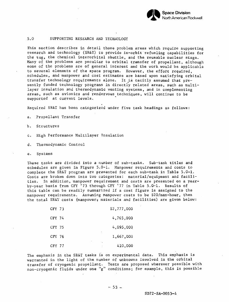
Space DivisionNorth American Rockwell
5.0 SUPPORTING RESEARCH AND TECHNOLOGY
This section describes in detail those problem areas which require supportingresearch and technology (SR&T) to provide in-orbit refueling capabilities forthe tug, the chemical interorbital shuttle, and the reusable nuclear stage.Many of the problems are peculiar to orbital transfer of propellant, althoughsome of the problems are of general interest and the work would be applicableto several elements of the space program. However, the effort required,schedules, and manpower and cost estimates are based upon satisfying orbitaltransfer technology requirements alone. It is tacitly assumed that pre-sently funded technology programs in directly related areas, such as multi-layer insulation and thermodynamic venting systems, and in complementingareas, such as avionics and rendezvous techniques, will continue to besupported at current levels.
Required SR&T has been categorized under five task headings as follows:
a. Propellant Transfer
b. Structures
c. High Performance Multilayer Insulation
d. Thermodynamic Control
e. Systems
These tasks are divided into a number of sub-tasks. Sub-task titles andschedules are given in Figure 5.0-1. Manpower requirements and costs tocomplete the SR&T program are presented for each sub-task in Table 5.0-1.Costs are broken down into two categories: material/equipment and facili-ties. In addition, manpower requirement and costs are presented on a year-by-year basis from CFY '73 through CFY '77 in Table 5.0-1. Results ofthis table can be readily summarized if a cost figure is assigned to themanpower requirements. Assuming manpower costs to be $20/man-hour, thenthe total SR&T costs (manpower j- materials and facilities) are given below:
CFY 73 $2,777,000
CFY 74 4,765,000
CFY 75 4,095,000
CFY 76 1,667,000
CFY 77 410,000
The emphasis in the SR&T tasks is on experimental data. This emphasis iswarranted in the light of the number of unknowns involved in the orbitaltransfer of cryogenic propellant. Tests are proposed wherever possible withnon-cryogenic fluids under one "g" conditions; for example, this is possible
- 53 -
SD72-SA-0053-4
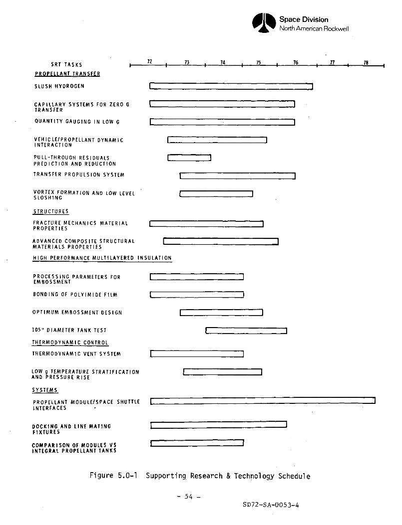
Space DivisionNorth American Rockwell
S R T T A S K S
PROPELLANT TRANSFER
SLUSH H Y D R O G E N
72 73 74 75 76 77 78
C A P I L L A R Y S Y S T E M S FOR ZERO GT R A N S F E R
Q U A N T I T Y G A U G I N G IN LOW G
V E H I C L E / P R O P E L L A N T D Y N A M I CI N T E R A C T I O N
P U L L - T H R O U G H R E S I D U A L SP R E D I C T I O N A N D R E D U C T I O N
T R A N S F E R P R O P U L S I O N S Y S T E M
V O R T E X F O R M A T I O N AND LOW LEVELS L O S H I N G
S T R U C T U R E S
F R A C T U R E M E C H A N I C S M A T E R I A LP R O P E R T I E S
A D V A N C E D C O M P O S I T E S T R U C T U R A LM A T E R I A L S P R O P E R T I E S
H I G H P E R F O R M A N C E M U L T I L A Y E R E D I N S U L A T I O N
P R O C E S S I N G P A R A M E T E R S F O REMBOSSMENT
B O N D I N G OF P O L Y I M I D E FILM
O P T I M U M E M B O S S M E N T D E S I G N
105" D I A M E T E R T A N K T E S T
T H E R M O D Y N A M I C C O N T R O L
T H E R M O D Y N A M I C VENT S Y S T E M
LOW g T E M P E R A T U R E S T R A T I F I C A T I O NA N D P R E S S U R E R I S E
S Y S T E M S
P R O P E L L A N T M O D U L E / S P A C E SHUTTLEI N T E R F A C E S
D O C K I N G AND LINE MATINGF I X T U R E S
C O M P A R I S O N OF MODULES VSINTEGRAL PROPELLANT T A N K S
Figure 5.0-1 Supporting Research & Technology Schedule
- 54 -SD72-SA-0053-4
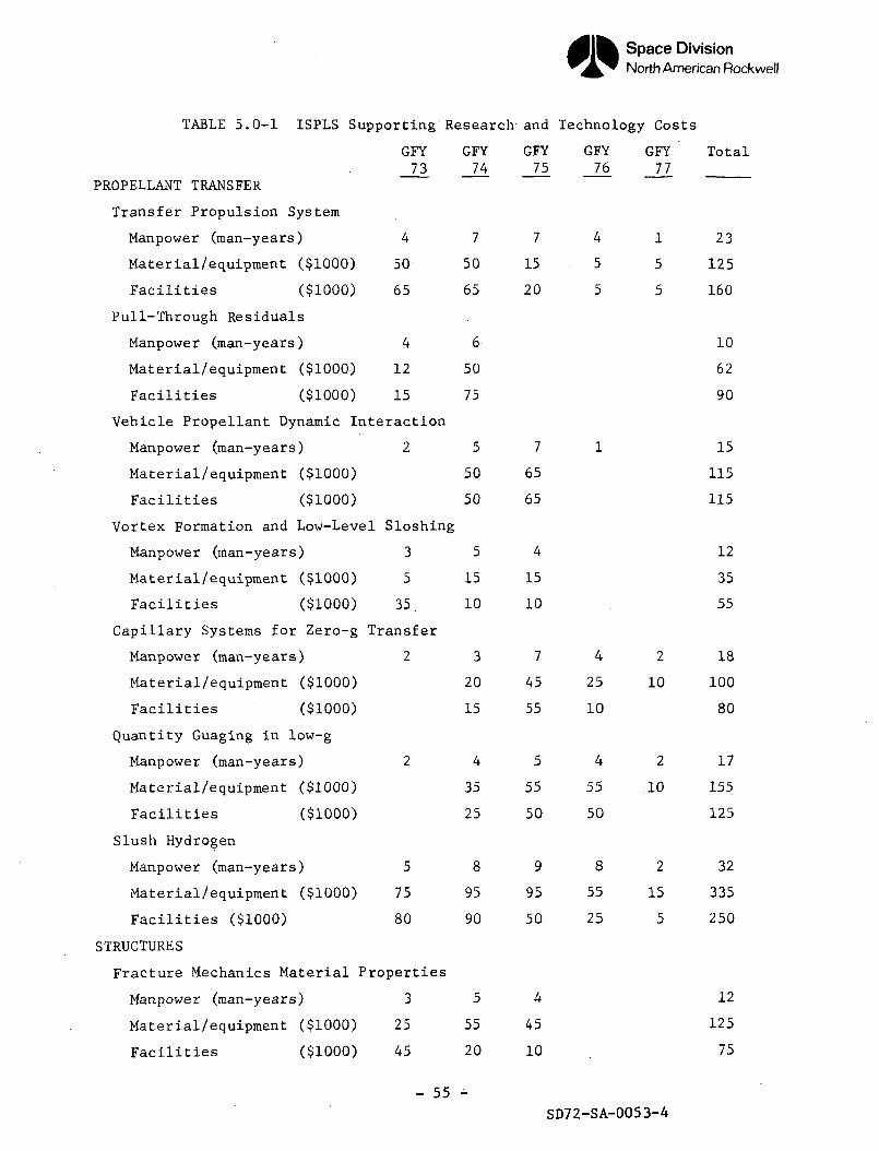
Space DivisionNorth American Rockwell
TABLE 5.0-1 ISPLS Supporting Research and Technology Costs
GFY GFY GFY GFY GFY " Total73 74 75 76 77
PROPELLANT TRANSFER
Transfer Propulsion System
Manpower (man-years) 4 7 7 4 1 23
Material/equipment ($1000) 50 50 15 5 5 125
Facilities ($1000) 65 65 20 5 5 160
Pull-Through Residuals
Manpower (man-years) 4 6 1 0
Material/equipment ($1000) 12 50 62
Facilities ($1000) 15 75 90
Vehicle Propellant Dynamic Interaction
Manpower (man-years) 2 5 7 1 1 5
Material/equipment ($1000) 50 65 115
Facilities ($1000) 50 65 115
Vortex Formation and Low-Level Sloshing
Manpower (man-years) 3 5 4 1 2
Material/equipment ($1000) 5 15 15 35
Facilities ($1000) 35. 10 10 55
Capillary Systems for Zero-g Transfer
Manpower (man-years) 2 3 7 4 2 18
Material/equipment ($1000) 20 45 25 10 100
Facilities ($1000) 15 55 10 80
Quantity Guaging in low-g
Manpower (man-years) 2 4 5 4 2 17
Material/equipment ($1000) 35 55 55 10 155
Facilities ($1000) 25 50 50 125
Slush Hydrogen
Manpower (man-years) 5 8 9 8 2 32
Material/equipment ($1000) 75 95 95 55 15 335
Facilities ($1000) 80 90 50 25 5 250
STRUCTURES
Fracture Mechanics Material Properties
Manpower (man-years) 3 5 4 1 2
Material/equipment ($1000) 25 55 45 125
Facilities ($1000) 45 20 10 . 75
- 55 -SD72-SA-0053-4
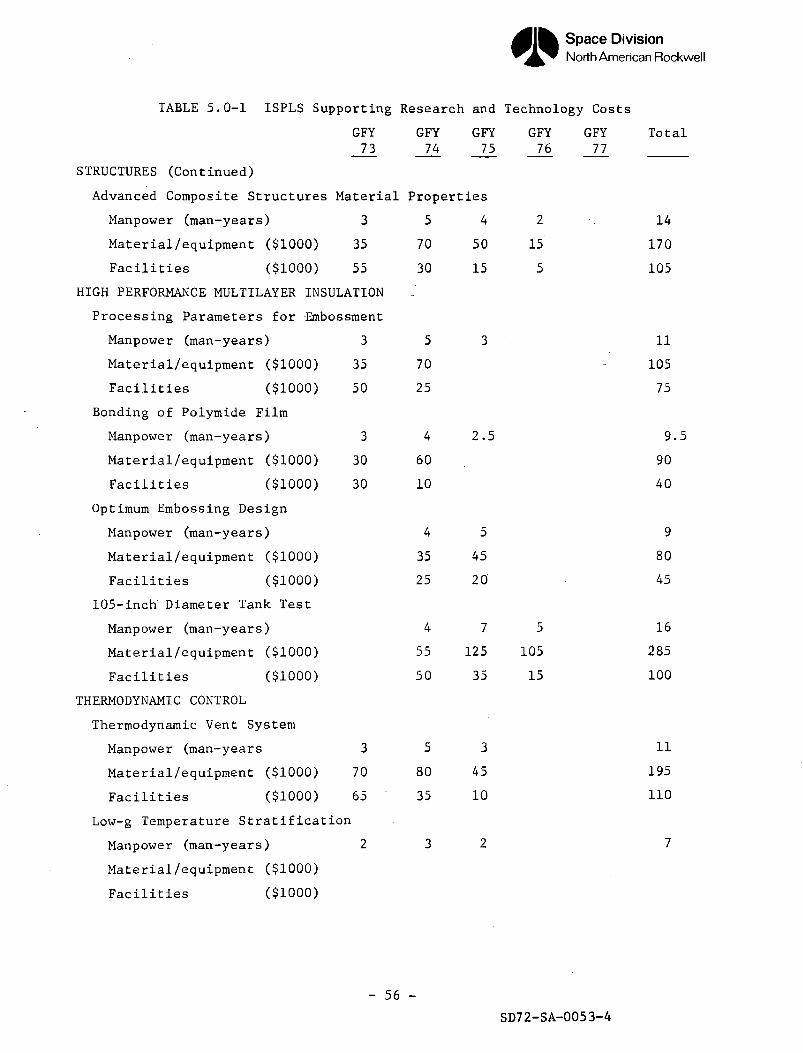
Space DivisionNorth American Rockwell
TABLE 5.0-1 ISPLS Supporting Research and Technology Costs
STRUCTURES (Continued)
GFY73
Advanced Composite Structures Material
Manpower (man-years)
Material/equipment ($1000)
Facilities ($1000)
3
35
55
GFY74
GFY GFY GFY75 76 77
Total
Properties
5
70
30
4 2 - .
50 15
15 5
14
170
105
HIGH PERFORMANCE MULTILAYER INSULATION
Processing Parameters for Embossment
Manpower (man-years)
Material/equipment ($1000)
Facilities ($1000)
Bonding of Polymide Film
Manpower (man-years)
Material/equipment ($1000)
Facilities ($1000)
Optimum Embossing Design
Manpower (man-years)
Material/equipment ($1000)
Facilities ($1000)
105-inch Diameter Tank Test
Manpower (man-years)
Material/equipment ($1000)
Facilities ($1000)
THERMODYNAMIC CONTROL
Thermodynamic Vent System
Manpower (man-years
Material/equipment ($1000)
Facilities ($1000)
Low-g Temperature Stratification
Manpower (man-years)
Material/equipment ($1000)
Facilities ($1000)
3
35
50
3
30
30
3
70
65
2
5
70
25
4
60
10
4
35
25
4
55
50
5
80
35
3
3
-
2.5
5
45
20
7 5
125 105
35 15
3
45
10
2
11
105
75
9.5
90
40
9
80
45
16
285
100
11
195
110
7
- 56 -
SD72-SA-0053-4
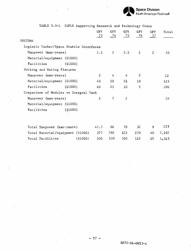
Space DivisionNorth American Rockwell
TABLE 5.0-1 ISPLS Supporting Research and Technology Costs
GFY GFY GFY GFY GFY Total73 74 75 76 77
SYSTEMS
Logistic Tanker/Space Shuttle Interfaces
Manpower (man-years) 1.5 2 2.5 2 2 10
Material/equipment ($1000)
Facilities ($1000)
Docking and Mating Fixtures
Manpower (man-years) 2 4 4 2 1 2
Material/equipment ($1000) 40 50 25 10 125
Facilities ($1000) 60 25 10 5 100
Comparison of Modules vs Integral Tank
Manpower (man-years) 5 7 2 1 4
Material/equipment ($1000)
Facilities ($1000)
Total Manpower (man-years) 47.5 86 78 32 9 253
Total Material/equipment ($1000) 377 790 625 270 40 2,102
Total Facilities ($1000) 500 550 350 115 10 1,525
- 57 -
SD72-SA-0053-4
Space DivisionNorth American Rockwell
with the vortex formation tests and the majority of the pull-through re-sidual tests. However, in many of the tests, use of cryogenic propellant isrequired. Additionally some of the tests must be performed in specialenvironments, such as low-gravity or high vacuum.
Manpower, costing, and schedules were determined by the above-mentionedconsiderations. Estimates are believed to be realistic and it is believedthat the required results can, indeed, be obtained if the programmed fundsand manpower are allocated.
- 58 -
SD72-SA-0053-4
Space DivisionNorth American Rockwell
5.1 PROPELLANT TRANSFER
5.1.1 Transfer Propulsion System with Long Duration Firing Capability
5.1.1.1 Problem Statement
The use of continuous linear acceleration for vapor/liquid interface controlfor transfer times of the order of 10 hours requires SR&T in the area ofengine development. As thrust must be maintained for long durations, it isdesirable that engine specific impulse be high. A value of specific im-pulse of 400 sec. has been used in the Trade Study Section of this report.This requires development of a LOX/LH2 system.
However, existing technology in the thrust range of interest (about 10 Ibs)is limited to earth storable propellant with lower values of specific im-pulse. Morever, even engines using storable propellants have not yetdemonstrated long duration operations.
The life limiting factor influencing system and engine operation is theoperational mode. The cyclic or pulsing mode, typical of attitude controlsystems, is the most stringent and limits manifest themselves in valve seatwear, thermal fatigue (expansion and contraction), injector erosion, andwear on bearings and other rotating equipment. On the other hand, steady-state operation, which permits the system to reach thermal equilibrium,minimizes wear from on-off operation and, of course, the fewer times thecomponents are actuated, the longer they will last. As the transfer pro-pulsion system is to operate continuously, the development problem ismitigated.
Although technological development of low thrust LOX/LH2 engines is lacking,Rocketdyne has conducted a program for NASA-LeRC on a 1500 Ib thrust, re-generative cooled LOX/LH2 engine (Contract iMS 3-14352). Based on a lifeanalysis performed by Rocketdyne, the life of this engine is estimated as1000 hours in the steady state mode. Such a life capability, if developedfor a low thrust LOX/LH2 engine (installed on the propellant module) wouldmeet the life requirements of the transfer propulsion system.
5.1.1.2 Required Effort
Research, analysis, and testing leading to the development of a low thrust(about 10 Ibs) LOX/LH2 engine with specific impulse of 400 sec. is required.Analytic studies and test programs to assure thermal isolation of theengine valve and to prevent overheating of the thrust chamber should beconducted. These studies should be oriented towards determining the optimumcombination of mixture ratio, film cooling and flow rate to control thermaldegradation. This work should be oriented towards steady-state engineoperation. However, some pulse mode testing should be included to assurestability under transient operating conditions.
- 59 -
SD72-SA-0053-4
Space DivisionNorth American Rockwell
5.1.1.3 Expected Results
A low thrust, LOX/LH- engine system with an overall specific impulseincluding system losses, of 400 sec. and a steady state life of severalhundred hours will be developed. This system will provide continuous linearacceleration for vapor/liquid interface control for in-orbit propellanttransfer.
5.1.1.4 Timing/Criticality
It is anticipated that engine system development will require three tofive years. Therefore, work should be initiated in 1972. As the effortcan proceed in parallel with the development of the logistic module, com-pletion can be as late as early 1977 (beginning of the Phase C study).
5.1.2 Improved Data on Pull-Through Residuals for Various Tank Bulkheadsand Baffles
5.1.2.1 Problem Statement
Vapor pull-through is caused by the non-uniform velocity of the flow intothe outlet lines of the propellant module. As the liquid surface nears theoutlet line the non-uniformities cause the interface to deform, leading togas ingestion and noncomitant trapped residual. This study, as well aspreceeding ones, has shown that pull-through residuals are a large portionof the total losses involved in transferring propellant. Furthermore, tradestudies conducted in this study phase have shown that auxiliary propulsionsystem (APS) propellant used to generate thrust for vapor-liquid interfacecontrol acts to decrease pull-through residuals. These pull-through re-siduals and APS propellant losses, which constitute the majority of thepropellant losses during transfer, are related. The trade studies showthat transfer time and total propellant losses are very sensitive to pull-through residuals.
Previous work (Reference 5.1.2.1-1) has shown that pull-through residualsdepend primarily upon tank geometry, Froude number, and Bond number. Re-liable data are available for flat-bottomed tanks with an axisymmetric outletunder conditions of Bond numbers greater than 300, Reference 5.1.2.1-1, andBond numbers less than 0.1, Reference 5.1.2.1-2. Experimental data at inter-mediate values of Bond number, which are often of practical interest, arelacking. The situation with regard to other geometries is considerablyworse. NR/SD has developed data for various tank bottom geometries forBond numbers above 300 (Reference 5.1.2.1-3) for limited ranges of D/d,where D is the tank diameter and d is the outlet diameter. The configura-.-tions studies were hemispherical bottom,conical bottom (45 and 30 degreeshalf angle), S-II reverse bulkhead type bottom, flat bottom with off-centeroutlet, and several bottom configurations with sump and/or baffle. Thedata from Reference 5.1.2.1-3 for hemispherical bottomed tanks, when com-pared to similar work done at NASA-LeRC (Reference 5.1.2.1-4) showed afactor of four discrepancy. This difference appeared to be due to differentvalues of D/d and to data normalization techniques. For the other config-urations ,data at intermediate and low values of Bond number are generally
- 60 -
SD72-SA-0053-4
Space DivisionNorth American Rockwell
lacking. Finally, future emphasis is anticipated in pull-through reductiontechniques, such as use of a sump and pull-through baffles and screens.
5.1.2.2 Required Effort
a. Conduct one-g scale model tests for the baseline geometry of thelogistic tanks over a range of Frcude numbers for several valuesof D/d. Present baseline geometry for logistic module tanks is asfollows:
For Tug and CIS - Reverse bulkhead, S-II type tank for LH2.Forty-five degree conical bottom tank for LOX.
For RNS - Elliptical bottomed tank with pull-throughbaffle for LH2.
Photographic measurements of pull through residuals will be made.
b. Conduct one-g scale model tests over a range of Froude numbers foralternatives to the LOX tank conical bulkhead and for improved tankoutlet configurations. These configurations will incorporate a sumpand/or baffles and screens. Additionally, the effect of anti-vortexand low level anti-slosh baffles on pull-through residuals will beestablished by model tests.
c. The above tests as they are conducted at one-g are of necessityconducted at Bond numbers above 300. These data will be adequateto similate accelerations as small as 3 X 10"- lb f/lb m for thelogistic modules. However, transfers are expected to take placeunder an acceleration level of 10~ to 10~5 it, f/lb m at which levelBond numbers are sufficiently low that capillary effects become ofsome importance. Therefore, a limited number of drop tower tests ofthe pull-through phenomenom should be conducted. These tests shouldbe conducted on the selected configurations over a small range ofconditions near that of the normal design. Photographic measurementsof pull-through residuals are to be made.
5.1.2.3 Expected Results
Pull-through residuals will be characterized ar, a function of D/d andFroude numbers for the baseline configurations. Performance verificationof the LOX tank conical bulkhead will be obtained or an alternate bulkheadchosen and tested. Advantages associated with the use of a sump and/orbaffles and screens will be assessed. Optimized outlet configurationswill be identified and tests conducted to predict residuals for theseconfigurations as a function of D/d, Froude number, and Bond number.
5.1.2.4 Timing/Criticality
As the proposed type of testing has been done before for simpler config-urations, and the tests are relatively straightforward compared to, thermo-dynamic tests, it is anticipated that this work can be accomplished shortlyafter the end of Phase A. Accomplishing this work at this early time willprovide visibility and enhance flexibility. However, this timing is not cri-tical and the test program could slip to the end of Phase B without serious impact.
- 61 - SD72-SA-0053-4
Space DivisionNorth American Rockwell
5.1.3 Vehicle and Propellant Dynamic Interaction
5.1.3.1 Problem Statement
Transfer of propellant from the logistics vehicle to the user vehiclecauses dynamic interactions between the propellant and the vehicle com-bination. The magnitude of the interaction problem increases as the ratioof propellant weight to total weight increases, and the problem existswith the three preferred methods for achieving propellant positioning(linear acceleration, centrifugal acceleration, and capillary devices).
Aside from the dynamic forces introduced by propellant transfer, fluidbehavior is affected by changes in vehicle motion due to the firing ofattitude control system (ACS) thrusters and docking impact. The firing ofACS thrusters and docking impact result in new mass distributions due toinduced propellant sloshing. An understanding of the transition mechanismfrom one fluid mass distribution to another is required to permit designof a workable ACS. Without this understanding, the sloshing and thrusterfiring (to counteract the sloshing) may reinforce the kinetic energy of thesystem and promote vehicle oscillation. Similarly, design data are requiredfor establishing an ACS rate damping mode for damping vehicle and fluidoscillations produced during docking operations. During attitude holdoperations, the periodic firing of ACS thrusters will cause the storedpropellants to oscillate in some manner related to the thruster firingfrequency. Data concerning the amplitude of the propellant oscillations andthe phase relationship between thruster firing and fluid sloshing are neededto determine the upper and lower bounds of thruster size and acceptablelimit cycle frequency.
5.1.3.2 Required Effort
The means available for the prediction of propellant behavior in large tanksduring transfer is considered inadequate. Analyses and experiments arerequired to provide data for math model verification and update prior to theselection of an optimum logistics module and user vehicle design. To ob-tain the necessary data, the effort outlined in the following task statementsis proposed.
a. Using existing computer programs and empirical data, perform an analysisof propellant hydrodynamics during transfer and establish dynamic inter-action effects. Include in the math model the influences on fluid be-havior of the following variables:
1. Momentum of entering fluid
2. Viscous damping
3. Acceleration level
4. Capillary forces
- 62 -
SD72-SA-0053-4
Space DivisionNorth American Rockwell
Establish the conditions under which fluid dynamic behavior will resultin:
1. Premature uncovering of the source tank outlet
2. Inability to assure liquid-free vapor return from the receiver tothe source tank
3. Use of excessive amounts of propellant for attitude control
b. Determine the slosh damping effect of adding baffles, screens, and/orinlet diffusers to source and receiver tanks. Perform tradeoff studiesof the additional weight and complexity of these devices against thereduction in ACS propellant usage during transfer.
c. Perform a literature search and tabulate applicable theories and datafor low-g slosh behavior. Compare these data with study objectives andestablish required additions to data.
d. Derive a set of exact analytical equations relating vehicle dynamicsto docking impact, ACS thruster firing, internal mass flow rates, andinternal slosh mass distributions. These equations will involve thefluid/vehicle tank interface dynamics and fluid properties in additionto the basic body dynamics. Simplify the equations in order to permitthe derivation of approximate solutions by analysis and/or digitalsimulation. Develop a comprehensive digital computer program for sim-ulating dynamic phenomena with the exact equations. Using both thesimplified and comprehensive programs, determine the influence of re-presentative disturbances on propellant dynamic behavior. Determinethis influence as a function of the ratio of propellant weight to totalweight and as a function of propellant transfer phase (beginning, middle,or termination).
e. With the vehicle/propellant transition dynamics (described as timefunctions of disturbances in Task d ) as input, use an operational 3-Dattitude control program for stability studies. Obtain stabilityboundaries as functions of slosh influences. Identify slosh parametersensitivities and select influence phenomena for test verification.Develop ACS compensation logic for various propellant slosh influences.Identify areas of contradictory requirements between slosh and attitudecontrol.
f. Using the results obtained in (a) through (e) , identify desirable,required, and mandatory zero-g test requirements. Define test facili-ties necessary to satisfy these test requirements. Prepare detailedtest plans. Fabricate test hardware and provide facilities.
g. Conduct experiments to verify predicted vehicle and propellant dynamicbehavior. These experiments will involve one or more of the following:
1. One-g tests
2. Drop tower tests
- 63'-
SD72-SA-0053-4
Space DivisionNorth American Rockwell
3. Zero-g tests in a KC-135 aircraft
4. Zero-g tests on board Skylab
h. Correlate test results with propellant and vehicle behavior predictedby analysis. Modify computer programs as necessary .to obtain thedesired agreement between analysis and experiments.
5.1.3.2 Expected Results
Completion of this effort will result in a computer program, backed up byexperimental data, for a parametric study of propellant slosh characteristicsand vehicle dynamic interactions. This program can then be used for es-tablishing ACS thruster size, and acceptable limit cycle frequency, methodsfor vehicle stabilization, methods of efficient slosh control, and methodsof vapor/liquid interface control.
5.1.3.3 Timing/Criticality
This work should be completed by the end of Phase B to support specificationof vehicle and subsystem design requirements and operational characteristics.
5.1.4 Vortex Formation and Low Level Liquid Sloshing
5.1.4.1 Problem Statement
In this present study phase the pull-through phenomenon has been emphasized,compared to other logistic module vapor/liquid interface disturbances. Pull-through residuals were important in establishing auxiliary propulsionsystem propellant requirements, total propellant requirements, and preferredtransfer times. However, during transfer for low liquid levels in thelogistic module, sloshing can aggravate the pull-through problem and in-crease residuals. Vortex formation due to induced propellant swirling ispotentially more deleterious than the pull-through phenomenon becausevortex formation may occur at any time during the transfer while pull-throughis limited to low liquid levels.
In the past, for booster and spacecraft propulsion systems, the aboveproblems have been prevented by anti-vortex and anti-slosh baffles (References5.1.4.1-1 and 5.1.4.1-2). Similar hardware fixes are expected to beapplicable to in-orbit propellant transfer; however, the low-g levels, longtransfer times, and spacecraft perturbations and orbital dynamics may requirenew baffle design, and, in addition, may entail operational constraintsduring transfer.
5.1.4.2 Required Effort
Analyses should be conducted to establish upper and lower limits on thevorticity that might be added to logistic module propellant prior to andduring orbital propellant transfer to the representative user vehicle. Inperforming this evaluation, due consideration must be given to vehicle
- 64 -
SD72-SA-0053-4
Space DivisionNorth American Rockwell
configuration and attitude, orbit, anticipated perturbations and maneuvers,and mission and transfer time duration. Work done for the "Vehicle andPropellant Dynamic Interaction" task will be utilized where possible. Basedon vorticity generated, tank geometry, and acceleration level an assessmentis to be made of the potential for vortex formation, the intensity of thevortex, and the concomitant free surface deformation. Based on this assess-ment, anti-vortex baffle design requirements should be formulated. A testprogram should be conducted to verify the performance of the anti-vortexbaffle design.
The "Vehicle and Propellant Dynamic Interaction" task should be utilizedto determine the range of propellant sloshing characteristics expected atlow liquid levels. Propellant anti-slosh baffle design requirements shouldbe formulated for these low liquid levels. A test program should be for-mulated to verify that the anti-slosh baffle will perform as required.
Finally, results of these studies should be utilized in the "Pull-ThroughResidual Prediction and Reduction," Task, paragraph 5.1.2. In particular,pull-through tests should be conducted with the anti-vortex and anti-sloshbaffles in place, to determine the effect of the baffles on pull-throughresiduals. Baffle modification required so as not to compromise the anti-pull-through function should be developed.
5.1.4.3 Expected Results
The propensity for vortex formation and low liquid level slosh will bedetermined. Design provisions to prevent or control these deleteriouseffects will be formulated. Tests will be conducted to verify the perfor-mance of baffle design. The effect of these baffles on pull-throughresiduals will be determined and modifications developed.
5.1.4.4 Timing Criticality
This work should be completed by the middle of Phase B to support conceptualvehicle design and allow timely interaction with the pull-through residualstask.
5.1.5 Capillary Systems for Zero-G Transfer
5.1.5.1 Problem Statement
Although trade studies conducted in this study show that the preferred vapor/liquid interface control technique is linear acceleration, there are somemajor advantages associated with the use of a capillary system for propellantacquisition and vapor/liquid interface control. Use of such a system permitsan appreciable reduction in auxiliary propulsion system propellant usage forthrust generation. This method of interface control requires no moving parts,reduces appreciably maneuver requirements compared to linear acceleration,and is compatible with a wide range of receiver configurations (i.e., e.g.location is not as important if only limited maneuvers are involved).
- 65 -
SD72-SA-0053-4
Space DivisionNorth American Rockwell
The proposed capillary system consists of capillary collector tubes in thelogistic module tanks for propellant acquisition from any region of thetanks under very low g conditions. The tanks in the receiver vehicle requirefill and vapor/liquid interface control baffles to permit orderly fillingand vapor return to the logistic module tank. A number of technology pro-blems must be solved if capillary devices are to become a practical alter-native. In particular, liquid-free vapor return to the logistic module tankunder low g conditions when the receiver tank is, say, more than 2/3 fullmay be most difficult. Vapor/liquid interface control baffles are proposedto provide the vapor return capability. However, the ability of thesebaffles to cope with propellant sloshing due to maneuvers or disturbancesis not proven at this time. The critical problem as regards the logisticmodule is the integration of the thermal control system with the capillarysystem. The requirement that the capillary devices contain sub-cooledpropellant must be compatible with propellant temperature and tank pressurerequirements.
5.1.5.1 Required Effort
Supporting research and technology effort for the logistic module capillarysystem should use the results of the recently completed "Cryogenic Acquisitionand Transfer" Study (Reference 5.4.2.1-1) as a starting point. Among theproblems addressed in that study were design requirements for steady statefeedout of adversely located propellant as well as the thermodynamics of thecapillary collectors during hot gas pressurized feedout and during long termcoast. Follow-on work should include the following tasks:
a. For a variety of capillary collector geometries and designs, determinehydrodynamic stability and structural integrity during flow start-upand shut down transients.
b. Verify flow loss characteristics of various capillary collectorsand associated manifolds, elbows, etc.
c. Evaluate alternate collector designs and configurations tominimize logistic tank trapped residuals.
d. Establish the compatibility of the capillary collectors with thethermodynamic control system, including verification that vaporformation within the collectors can be prevented or held tonegligible levels.
The four tasks above involve primarily subscale experimental tests at one g.Tasks (a) and (b) require non-cryogenic testing with limited confirmingexperiments with cryogenic propellant. Task (c) requires limited verifica-tion testing under low-g conditions. Potential test facilities for thesetests are the drop tower, the KC-135 aircraft, and Skylab. Task (d) re-quires a comprehensive test program using cryogenic propellant. For thislast task the effect of various parameters will be investigated includingcollector design, type of thermodynamic control system, percentage heliumin ullage, and ullage fraction.
- 66 -
SD72-SA-0053-4

Space DivisionNorth American Rockwell
SR&T is also required to support the design and operational capability ofthe user vehicles. Here the bulk of the testing will require a weightlesscondition. A small amount of refill testing of the baseline design shouldbe conducted under weightless conditions to verify that orderly refill canbe achieved. The required testing can be limited because it is anticipatedthat the drop tower tests conducted by NASA-LeRC will provide the bulk ofthe required data.
To assure that liquid-free vapor return can be realized, the capability ofthe baffles to control the vapor/liquid interface during maneuvers andperturbations must be proven. Towards this end drop tower tests where themodel tank is translated or rotated (pitch or yaw) during the free fallin a manner to simulate the range of expected disturbances should be con-ducted. Various baffle configurations should be investigated. Confirmationtesting with a scaled-up model should be conducted in the KC-135 or Skylab.Cryogenic fluid need not be utilized in these fluid dynamic experiments.
5.1.5.2 Expected Results
For the logistic module the proposed program will yield basic data on fluidflow and thermodynamic phenomena within the capillary collectors. Hydro-dynamic stability, flow losses, trapped residuals and propensity for vaporformation will be determined for a variety of capillary collectors. Theabove results will provide the basis for a choice of an efficient reliablecapillary collector design and thermodynamic control technique.
For the user vehicle the proposed program will provide sufficient data toallow specification of refill and vapor/liquid interface control baffledesign requirements. Selection of a baseline baffle system can be accom-plished with a high degree of confidence.
5.1.5.3 Timing/Criticality
The work must be well along by the beginning of Phase B to permit a timelyevaluation of capillary systems as an alternative to linear accelerationfor vapor/liquid interface control. The SR&T effort must be completed bythe beginning of Phase C to support the design effort, should capillarysystems be selected for vapor/liquid interface control.
5.1.6 Quantity Gauging in Low Gravity Environment
5.1.6.1 Problem Statement
Gauging of cryogenic propellant in a low or zero-g environBient remains acritical technology area. Technology development emphasis over the pastdecade has been on radio frequency gauging, sonic gauging, and nuclearradiation gauging with the intent of developing a zero-g capability. Theobjective of this work has been to develop systems that would functionreliably for any distribution of liquid and vapor (e.g., sloshing liquid,froth, etc.). To date, this work has not been fruitful in leading to thedevelopment of a reliable, accurate zero-g gauging system.
- 67 -
SD72-SA-0053-4
Space DivisionNorth American Rockwell
It is believed that violent agitation is an exceptional situation andcertainly not one for which a vital gauging requirement exists. As the pre-sent baseline employs low-g thrusting for vapor/liquid interface control,it is appropriate to develop a gauging system for propellant under reasonablecontrol in a low-g (10~ to 10~5 lb. f/lb m) field. Two possibilities toachieve this end are point sensors which are contoured to prevent capillarywetting, and continuous sensors in the form of a thin resistance-type wirecovering the desired length of the tank. Such a wire, because of its smalldiameter and vertical mounting, would have only a tiny meniscus. Of course,a correction would be required for the meniscus at the tank wall and at tankinternal hardware. Both approaches are based on the principle that heattransfer from an electrically heated wire is different depending uponwhether the wire is in liquid or vapor. This is reflected in changes oftemperature and electrical resistance of the wire which can be measuredremotely as an indication of wetting. The same basic principle was used forthe existing Saturn S-II point sensors, except that capillary effects andheat transfer rate variation with acceleration level was of little concernfor the S-II high acceleration level.
The major problem associated with the use of resistance wire is that heattransfer from the wire will differ greatly over the 10^ to ^0^ fold rangein acceleration level from earth to orbital conditions. To overcome errorsintroduced by stray resistance changes and variations in heat transferconditions, it may be necessary to use self-calibration techniques andcircuitry. One of the techniques considered involves the alternate appli-cation of a high and low current level to each sensor to calibrate its in-flight resistance at ambient temperatures vs self-heating temperatures.These functions could be handled automatically by the on-board general pur-pose computers and data processing equipment presently planned on new-generation space vehicles.
5.1.6.2 Required Effort
A preliminary analysis followed by a test program is required. The analysiswill identify favorable point sensor and continuous sensor designs, includingconfiguration and materials, as well as determine instrumentation require-ments and current levels. The first phase of testing will be conductedat one-g using model and cryogenic fluids. Cryogenic testing will be con-ducted in a low heat leak dewar system at current levels appropriate to one-g conditions. Heat transfer from the electrically heated wire to the liquidand vapor phases is affected by the acceleration level. The very low accel-eration levels of space will result in roughly a 10-to 20-fold decrease infree convection heat transfer rates and are likely to change the mechanism ofheat transfer from free convection to conduction or film boiling.
As severe difficulties are expected in simulating all of the aspects of low-g heat transfer at one-g conditions, low-g testing will also be required.A progression of testing is required, proceeding from drop tower tests,through KC-135 tests, to long-term orbital tests in the Skylab or post-Skylab orbital test beds. These tests will investigate low-g capillarywetting (meniscus effect) and heat transfer phenomena associated with low-g.gauging applications.
- 68 -
SD72-SA-0053-4
Space DivisionNorth American Rockwell
5.1.6.3 Expected Results
Materials, operating conditions, and instrumentation required for discreteor continuous heated wire systems for low-g gauging applications will bedetermined. Preferred designs and instrumentation will be identifiedfrom one-g testing. Low-g testing will determine necessary modificationsto provide accurate, reliable low-g gauging systems for LOX and LH_.
5.1.6.4 Timing/Criticality
Low-g quantity gauging presents formidable development problems andsupporting research and technology will be required through the beginning
of Phase C.
5.1.7 Hydrogen Slush Manufacture, Storage, and Transfer
5.1.7.1 Problem Statement
Slush hydrogen, SH , has been evaluated for potential application to thepropellant logistic program in Volume 3 of this report. There it wasshown that the advantages of slush over normal boiling point hydrogendepend greatly on user vehicle size, traffic model, and propulsion systemduty cycle.
For user vehicles which require large quantities of hydrogen and forwhich many missions are programmed the use of SH may be feasible. Witha high-rate traffic model the anticipated large costs of developing SHfacilities, equipment, and technology can be amortized over more flightswhich may yield lower costs per pound of SH placed into orbit. Thus itis unlikely that SH« can be applied economically to low level spaceprograms or where the tug is the main user. However, for the more ambitiousprograms where the CIS or the RNS stage are the primary propellant users,significant cost savings may be realized. Application of SH~ to theseprograms depends upon technology advances in several areas. These tech-nology problems are described in Volume 3 and therefore are only enumeratedbelow:
a. Compatibility of low vapor pressure of SH_ with atmospheric pressureduring ground handling.
b. Manufacturing state-of-the-art advances, e.g., manufacturing SHdirectly in the tanker.
c. Instrumentation and measurements
d. Rheological properties
e. Temperature stratification
f. Percolation in dead-ended lines.
g. Aging process
- 69 -
SD72-SA-0053-4
Space DivisionNorth American Rockwell
h. Special provisions for orbital transfer
Investigations in most of these problem areas have been andare presently being conducted at NASA/MSFC, National Bureau ofStandards, Government contractors, etc. Schedule and costingdata assume the continuing use of these facilities, modifiedas required, to support the logistic module requirements for SH..
5.1.7.2 Required Effort
a. Investigate hydrogen slush manufacturing and transfer techniquesapplicable to the propellant module. Based on this investigationdevelop a procedure for loading slush into a propellant moduledesignated to fit into the cargo bay of the space shuttle andfeaturing thin-walled, lightweight construction. Include inthe procedure considerations for thermal stratification anddetails of a helium pressurization technique to prevent collapseof the module due to negative pressure differentials duringground operations. Identify requirements for special equipment,e.g., transfer pump, mixers, and helium pressure expulsion.
b. Develop procedures and instrumentation for the measurementof hydrogen slush mass and quality.
c. Conduct analyses to establish operations and design requirementsfor storage of SH in the propellant modules on the ground, duringboost, and in orbit prior to transfer.
d. Conduct analyses to establish special procedures and designrequirements for orbital transfer of SH .
e. Conduct a sub-scale test program at one-g to verify the analysesof tasks a, b, and c, and to obtain data to design zero-g teststo verify task d.
f. Conduct drop tower and KC-135 tests to obtain data to support andconfirm the analyses of task d. If required, plan and conduct apost Skylab orbital test to assure that desired performance andsystem functioning will be achieved. Manpower and cost for thisorbital test are not reflected in Table 5.0-1, as it is notclear at this time that such testing will be necessary.
5.1.7.3 Expected Results
The required technology to manufacture, store, and transfer SH,, for pro-pellant module applications will be achieved.
5.1.7.4 Timing/Criticality
Considerable work on this alternative needs to be conducted. Work mustcontinue until the beginning of Phase C to complete all of the requiredtasks, and yet allow support of the Phase C effort.
- 70 -
SD72-SA-0053-4
Space DivisionNorth American Rockwell
5.2 STRUCTURES
5.2.1 Fracture Mechanics Material Properties
5.2.1.1 Problem Statement
The fracture mechanics analytical procedures for selecting the materialand determining the necessary skin thickness for the pressurized tanksrequire that three material properties be known:
K Critical plane strain-stress intensityJ_U
K Stress intensity at which a given flawwill continue to grow under a sustainedload.
da/dN Flaw growh rate for different cyclicvariations in stress intensities ( K)
Utilizing these properties, it is possible to determine the largest flawwhich could exist in a pressurized vessel after a proof test and the amountof flaw growth which would occur during the operational cycles, such thatno flaw growth would occur under sustained load and the flaw could notgrow through the thickness of the material.
The material properties indicated above are available for many materials,including 2219-T87 and 2014-T651 aluminums being considered for thepropellant tanks of the logistic module. However, when dealing withvery thin materials (less than 0.2 inches) the commonly accepted valuesof Kj£ and KTJI are no longer applicable. The thickness of material beingconsidered for the logistic module design is generally less than 0.1 inch.Therefore, material properties must be developed for the materials andthickness ranges being considered.
Without these data it would be impractical to perform a fracture mechanicsanalysis of the propellant tanks. With no fracture mechanics analysis,it would be necessary to apply an additional safety factor to the propel-lant tanks to guard against failure resulting from undetected flaws. Theimpact of the resulting high safety factor would be an unnecessarilyheavy logistic module with reduced LOX/LH. payload capacity.
5.2.1.2 Required Effort
A fracture mechanics material properties test program is needed to providesufficient data to enable the final selection of the propellant tankmaterial and to establish material properties so that a fracture mechanicsanalysis of the final design can be performed. The program will involveobtaining data on at least two materials being considered for the propel-lant tanks and will include parent and welded metal testing to determine:
- 71 -
SD72-SA-0053-4
Space DivisionNorth American Rockwell
a. Failure stress vs initial flaw size for various flaw configurations(long, short, shallow, and deep).
b. Sustained load flaw growth threshold stress vs flaw size for variousflaw configurations.
c. Spot check of flaw growth rate data (da/dN) to assure that existingdata are valid in the thickness ranges being considered.
Data will be obtained at room and cryogenic temperatures for three dif-ferent thicknesses in the thickness ranges being considered.
5.2.1.3 Expected Results
Initial data received from the test program will be used to screen andselect the material to be used in the design of the propellant tanks. Sub-sequent data will provide remaining information needed to develop thedesign curves required for performing a fracture mechanics analysis.
Results of the test program and subsequent analysis will dictate theproper operating stress of the propellant tanks. The data will also indi-cate which proof test, pneumostat test, or cryoproof test will be mosteffective in verifying structural integrity of the tanks. The finalproduct of the program will be the ability to design an efficient light-weight propellant tank structure for the logistics module.
5.2.1.4 Timing/Criticality
The development of the fracture mechanics material properties is con-sidered essential to the logistics module development program and criticalin terms of selection of the material, establishment of realistic designmargins, and, hence, attainment of realistic propellant tank design weights.
Consequently, the test program should be initiated before the Phase Bsystem study so that material selection can be made during this phase.Complete fracture mechanics material properties for the selected materialmust also be made available at initiation of the Phase C effort so thatfinal sizing of the propellant tanks can be accomplished.
5.2.2 Advanced Composite Structure Material Properties
5.2.2.1 Problem Statement
Extreme emphasis on low inert weight for the logistics module designnecessitates the consideration of advanced composite materials. Currenttechnology, which is adequate for fabrication, consists of hand layuptechniques in conjunction with some mechanized equipment used for flatpanel layups and filament winding of tubular structures similar to thatused in aircraft design. Since the aircraft industry is the major user ofcomposite materials and is not concerned with cryogenic temperatures,sufficient data for reliable design allowables at cryogenic temperaturesis limited. Consequently most of the cryogenic mechanical property data
- 72 -
SD72-SA-0053-4
Space DivisionNorth American Rockwell
being used for design are based either on engineering judgement or extra-polation from limited cryogenic test data.
5.2.2.2 Required Effort
Design allowable data will be generated at room temperature and -300°Ffor boron epoxy, graphite epoxy and S-glass filament wound compositeswhich are being considered for the logistics module. Properties to bedetermined include orthotropic values of F , F , F , E, E and G. Theinvestigation will also evaluate effects orlayup orientation, compositethickness, fastener attachment parameters (optimum hole diameter andspacing), and specimen configuration.
5.2.2.3 Timing/Criticality
This research should be accomplished prior to the completion of thePhase B program study so that the influence on system design analysis andprogram costing can be evaluated.
5.3 HIGH PERFORMANCE MULTILAYER INSULATION
5.3.1 Processing Parameters for Producing a Permanent EmbossmentPattern in Plastic Film Used for Multiple Layer Insulation
5.3.1.1 Problem Statement
The most efficient thermal insulation, per unit weight, for cryogenicliquid tanks consists of multiple layers of thin plastic film whichhave been metallized and embossed. The embossment pattern minimizesdirect thermal conduction through the insula'tion by maintaining spacewith minimum direct contact area between film layers. Other types ofmultiple layer thermal insulation systems use flat layers of film or foilwhich are held apart with mechanical spacers that add additional weightand bulk to the insulation system.
The embossment pattern in plastic film material normally tends to flattenout when the film is exposed to elevated temperatures. Embossed poly-ester (Mylar) film loses embossment height during exposure to temperaturesas low as 140 F. The loss of embossment height by plastic films dependson many factors which have not yet been quantitatively established.
These factors include time and temperature used to produce the embossmentpattern in the film, and the post-embossment exposure conditions of tem-perature and compressive load for specific time intervals. The generictype and the thickness of the film are also important factors. Sincethe multiple layer insulation used on the logistics module will be exposedto 200°F in service, Mylar film is inadequate for this application.
The embossed shield material is procured commercially and the patternsutilized to date were chosen on basis of availability, but were not opti-mized to provide the best reflective surfaces. Recent procurements byNR have also demonstrated that suppliers cannot duplicate prior orders;therefore, successive batches are unpredictable.
- 73 -
SD72-SA-0053-4
Space DivisionNorth American Rockwell
Because of these two conditions, the following problems relating to thematerial must be solved.
a. Identify a better substrate material than Mylar and/or developa superior embossing technique. Kapton film is believed to bethe best available candidate material, but its ability to hold adeep embossment has not been shown.
b. Analyze the commercial patterns provided by suppliers, determinehow the patterns should be changed to provide optimum layerdensity, fabricate experimental patterns as determined in (a) anddemonstrate acceptability. A plan is needed to ensure that commer-cial suppliers can produce the material with the optimized emboss-ment pattern.
5.3.1.2 Required Effort
a. Polyimide (Kapton) film material, one-quarter mil thick, is to beembossed at various temperatures up to 750°F for various timeperiods up to 15 minutes. The Kapton film is a good candidatebecause it has high temperature resistance and is available inrelatively thin gages. Specimens of Kapton film embossed undereach of several different conditions of time and temperature areto be measured to determine their embossed thickness and lineardimensions. The specimens are then to be exposed to a temperatureof 200°F for one hour while under a compressive load of 0.1 psi.After cooling, the embossed thickness and linear dimensions ofthe specimens are to be remeasured and the effects of the exposureto temperature determined. The effect of 10 exposure cycles of 200°Ffor one hour under a 0.1 psi load is to be determined for thespecimens by the same method.
b. Samples of materials provided by various suppliers for priorprograms will be analyzed to determine the number of peaks inthe embossment pattern per unit area. Suppliers will be contactedto determine if other patterns are available. New patterns willbe defined to optimize the depth of embossment and the number ofpeaks per unit area. Samples will be produced using the materialsand techniques developed in (a). These will be tested to demon-strate acceptability. A plan will be set up to coordinate pro-duction and quality control of the optimized pattern by commercialsuppliers.
5.3.1.3 Expected Results
a. This test program is expected to establish processing parameters forproducing an embossment pattern in Kapton film which will remaindimensionally stable during exposure to 200°F under low compressiveloading. Kapton film was experimentally embossed at a relativelylow temperature and did not have as deep an embossment pattern asis desired for multiple layer insulation film. However, the speci-men did show that Kapton film can be embossed. Because Kapton isa thermosetting plastic, it can be expected to retain its emboss-ment pattern better during heating than does Mylar, a thermoplastic material
- 74 -
SD72-SA-0053-4
Space DivisionNorth American Rockwell
b. The results of this program are expected to identify causes ofdiscrepancies in prior studies. It is also expected that thisprogram, when coupled with improved metallized coatings and commer-cial production techniques, will provide a superior insulation systemwith optimum thermal performance, low weight and simple manufacturingcharacteristics.
5.3.1.4 .Timing/Criticality
Development of this embossing procedure is required in time to assure thatthe environmental conditions which will be imposed on the insulationsystem during purging of the insulation and entry heating inside thecargo bay will not degrade the embossment pattern. Therefore, the researchshould be accomplished prior to the end- of the Phase B study.
5.3.2 Bonding of Polyimide (Kapton) Film to Itself
5.3.2.1 Problem Statement
During fabrication of multiple layer insulation systems, it is necessaryto join individual sheets of film together along the edges to producecontinuous layers of film which will not shift during mechanical loadingin service. Where polyester (Mylar) film is used, the edges of the filmcan be quickly heat-bonded together. However, where higher servicetemperatures are expected, as in the case of the logistic module, it willbe necessary to use polyimide (Kapton)film. Kapton film is thermosettingand is not heat-sealable. Therefore, some method must be developed forbonding Kapton film to itself.
To solve this problem, the duPont Co. manufactures a form of polyimidefilm, designated Kapton Type F, which is coated on one surface with FEPTeflon resin to produce a heat-bondable surface. However, this type ofmaterial is unsuitable for multiple layer insulation, both because theweight of the Teflon resin coating causes an unacceptable increase in theinsulation density and because metallizing the uncoated surface of thepolyimide results in processing difficulties. For example, Teflon couldcontaminate the opposite surface of the film and prevent good adhesionof the metallized coating, or the heat-rise which occurs during metallizingcould cause premature bonding of the film. Several different types ofadhesives are recommended by duPont for bonding polyimide film. None ofthese adhesives is considered acceptable for fabricating cryogenic in-sulation systems because they all require either a heat cure for at leasttwenty minutes or a much longer room-temperature cure.
On the basis of the foregoing information it appears that the most accept-able method for bonding polyimide film to itself is to apply an FEPTeflon dispersion coating locally to cut sections of film where the materialis to be bonded during fabrication and installation of the insulation.The material can then be heat bonded easily and quickly, using a conven-tional hand-operated heat sealer. The FEP Teflon dispersion coating canbe applied to local areas of polyimide film either by spraying or brushing.Teflon coatings applied by this procedure do not adhere to film as well ascommercially applied heat-bondable coatings which usually are heat-cured
- 75 -SD72-SA-0053-4
Space DivisionNorth American Rockwell
onto the film. However, these dispersion coatings do adhere well enoughto remain intact during normal handling of the film in fabricating theinsulation system, and following the heat-bonding operation the FEPTeflon can be expected to exhibit good adhesion to both film surfaceswith which it is in contact.
5.3.2.2 Required Effort
Various quick-setting cements will be obtained and tested to determinetheir bonding strength and curing times when used to bond Kapton filmto itself. Also, various FEP Teflon dispersion coatings will be appliedto Kapton films which will then be heat-bonded together at varioustemperatures, pressures and time intervals. The resulting heat bonds willbe tested to determine their strength. •
The efficiency of each of the bonding methods investigated will be deter-mined at cryogenic, room temperature, and the maximum expected servicetemperature of 200°F. In addition, Eastman 910 cement and Devon Corp."Zip Grip" 10 cement which cures in a matter of seconds at room tempera-ture, should be tested as adhesives for Kapton film. Cements with appre-ciably longer curing times would increase fabrication time of the insulationsystem and would not be acceptable.
5.3.2.3 Expected Results
The test results are expected to identify both a quick-setting adhesivefor Kapton film and a system for heat-bonding Kapton film. The adhesive-bond and heat-bond are both expected to be acceptable for service tempera-tures up to 200°F.
5.3.2.4 Timing/Criticality
Development of a procedure for bonding Kapton film to itself is necessaryto assure proper fabrication of multiple layer insulation systems overthe liquid hydrogen tank on the logistic rfl°4ule. Therefore, the researchshould be accomplished during the Phase B study.
5.3.3 Calorimeter Test of Optimized Embossed Multiple Layer Insulation
5.3.3.1 Problem Statement
Recent studies and test programs at NR show that lightweight high per-formance multi-layer insulation systems can be produced utilizing commer-cially supplied embossed aluminized Mylar for reflective shields. Theseprograms disclosed that best thermal performance occurs when naturalshield density is 30 to 40 layers per inch. Substituting Kapton for Mylarraises the operating temperature limit from +140 F to approximately +300 F(as required for the logistic module).
Test programs were proposed in paragraph 5.3.1.2 to optimize the em-bossment pattern and to develop techniques for embossing the Kapton material.Laboratory tests are proposed to verify the adequacy of the new pattern and
- 76 -
SD72-SA-0053-4
Space DivisionNorth American Rockwell
procedures. A calorimeter test is needed to verify thermal performanceof a system utilizing the new patterns and material in the cryogenicenvironment.
5.3.3.2 Required Effort .
After the optimized material becomes available, a test program will beconducted in which a guarded calorimeter will be insulated with the newmaterial. It will be tested with LH in a chamber capable of maintaininga vacuum below 10 Torr.
Following the test runs in which structural integrity and thermal per-formance will be determined, the specimen will be sectioned. Coordinatingdata will be obtained from flat plate calorimeter.
5.3.3.3 Expected Results
This test program is expected to demonstrate thermal performance of theoptimized embossed aluminized Kapton multilayer insulation system. Thesystem is expected to be competitive with other concepts yet weigh less.
5.3.3.A Timing/Criticality
Demonstration of this concept and these materials is necessary to assureproper selection of an insulation system for the logistics module.Therefore, the program should be accomplished prior to the end of thePhase B study.
5.3.4 105-Inch Diameter Tank Insulation System Test
5.3.4.1 Problem Statement
Studies are currently underway to develop a lightweight, high performanceinsulation system concept using commercially produced embossed aluminizedMylar for the reflective shields. It has been shown that performance canbe improved up to 50 percent by optimizing and stiffening the embossmentpattern. It was also shown that the shield material should be changedto Kapton if the system will experience compressive loads at temperaturesin excess of +150°F.
Studies are proposed in paragraph 5.3.1.2 to optimize the embossment pat-tern and to provide the procedures for producing the pattern in Kapton.A study is also proposed in paragraph 5.3.3.2 to permit small scalecalorimeter tests on this material.
An additional study is required to extend the material development tech-nology to large scale tests and to verify the insulation performance andweight. NR recommends the use of an existing tank such as the 105-inchdiameter tank and test facility at NASA/MSFC (which is currently beingused to test aluminized Mylar insulation) to minimize costs and to ensurecompatibility in results with prior system tests.
- 77 -SD72-SA-0053-A
Space DivisionNorth American Rockwell
It will be necessary to obtain sufficient satisfactory insulation materialto apply to the large scale tank; develop the proper techniques for apply-ing, inspecting, and repairing the insulation; and to conduct tests onthe large scale tank to verify thermal performance of the installed in-sulation system.
5.3.4.2 Required Effort
a. From prior studies the optimized embossment pattern will be definedby the number of peaks per square inch, depth of embossment, shapeof peaks, dips, etc. Process procedures for embossing the patternon Kapton will be defined in terms of temperature of embossmentprocess, time, chill rate, chill temperature, contact pressure,etc. Additional definitive materials properties data will be avail-able from the prior lab studies. Capability of commercial suppliersto repeatedly produce the material will be evaluated and adequatematerial obtained.
b. An insulation system will be designed for the large scale calori-meter. An application model will be selected prior to start of thedesign. The insulation system design will be limited to the featuresnecessary to evaluate the performance and determine operationalcharacteristics of the materials and the concept.
A natural-lay spacerless configuration will be utilized and willbe oriented to provide maximum thermal performance with least weightpenalty for the application model profile. The insulation systemwill be installed by manufacturing personnel with normal qualitycontrol inspection. Records will be kept to enable evaluation ofproducibility of the embossed Kapton compared to other materialsand concepts.
c. After the insulation system is installed and checked, it will beshipped to the facility selected for testing. Tests will be ofsufficient number to ensure both thermal and structural performancecharacteristics are measured and evaluated.
5.3.4.3 Expected Results
This program is expected to result in definition of installation, inspec-tion, and repair procedures for fabrication of lightweight, high per-formance multilayer embossed insulation systems. Thermal and structuralperformance of the Kapton insulation system will be thoroughly evaluatedwith respect to other materials, combinations, and concepts.
5.3.4.4 Timing/Criticality
Assurance of availability of these enhanced materials is necessary intime to permit selection of a high performance insulation system thatwill ensure minimum payload penalty. It should therefore be complete priorto end of Phase B study.
-78 -
SD72-SA-0053-4
Space DivisionNorth American Rockwell
5.4 THERMODYNAMIC CONTROL
5.4.1 Thermodynamic Venting System (TVS)
5.4.1.1 Problem Statement
In a low gravity environment, the containment of a cryogenic liquid iscomplicated by the lack of positive control of the position of the liquidand gas phases. During orbital flight prior to propellant transfer therewill be, in general, no provision for positive control of the vapor/liquid interface. Boiloff vapors must be vented, or else energy mustbe removed from the propellant tanks to control the tank pressure. Thepotential loss of propellant by entrainment of liquid in the vented vapormakes usage of a thermodynamic vent system, to ensure vapor venting alone,a necessary requirement.
The thermal control system considered for control of logistics module in-ternal thermodynamics, includes some form of thermodynamic vent heat ex-change. The thermodynamic vent heat exchange system includes an expansionvalve where LE is throttled to a relatively low pressure and temperature.This provides the necessary temperature differential for extraction ofheat from the propellant by an appropriate heat exchanger. Reliableanalytical procedures have not been fully developed for this form ofventing. Although the feasibility of this vent concept, using compactheat exchangers and mixers, has been experimentally established at one-g,it remains to be demonstrated at low gravity.
5.4.1.2 Required Effort
Experimental one-g tests for simulation of the low gravity internal tankthermodynamics for a cryogenic propellant, in conjunction with the opera-tion of a TVS, should be performed.
An outline of the one-g TVS fabrication and test program for a wallmounted heat exchanger is given below:
a. Define operational parameters
1. Heat loads to tank walls2. Acceleration field3. Tank sizes, wall thicknesses, type of metal4. Pressure levels
b Determine scaled test parameters for one-g earth experiment for scaledtank (high vacuum chamber tests anticipated).
c. Determine thermodynamic vent operational requirements for zero g
1. Propellant flow rates2. Tube spacing3. Attachment points4. Two-phase heat transfer5. Throttle valve sizing
- 79 -
SD72-SA-0053-4
Space DivisionNorth American Rockwell
d. Scale determinations, (c), for scaled one-g test.
e. Design experiments to cover range of (a), (b), and (d).
f. Design test vessel, insulation, TVS attachment, control system.
g. Conduct experiments
h. Evaluate effectiveness of TVS relative to
1. Operational adequacy and flexibility2. Reliability for liquid thermal control and pressure control
5.4.1.3 Expected Results
The primary result of this program is that the thermal effectiveness ofthe tube spacing and TVS flow rate controls will be determined and theoverall feasibility of this method of thermodynamic control verified.In addition, the results of the experimental program will be used in thefurther development and verification of analytic models to predict liquidtemperature stratification and tank self-pressurization under low gravity.
5.4.1.4 Timing/Criticality
It is believed that the considerable recent work done by governmentagencies (e.g., NASA/MSFC and NASA/LeRC) and government contractors onTVS will reduce somewhat the necessary work required to support the TVSfor the logistic module. Additionally, TVS technology required for thelogistic module, which is in orbit for a relatively short time, is lessthan that required for the tug and the CIS vehicles which have long dura-tion orbital missions. Hence, it is believed that the required programcan be completed by the middle of Phase B, in time to support conceptualand final design of the logistic module.
5.4.2 Low Gravity Temperature Stratification and Pressure Rise
5.4.2.1 Problem Statement
During logistic tanker orbital operations prior to propellant transfer,tank pressure rise may exceed that which would occur if the cryogenicliquid and vapor phases were well mixed. Additionally, localized propel-lant heating may occur. Both effects are due to thermal stratification dueto heat leakage. Analytical tools (Reference 5.4.2.1-1) to predict low-gstratification and pressure rise have been developed for a tanker con-taining non-sloshing propellant in an earth oriented attitude. Data toverify this model are not available, although one-g stratification datadeveloped during''Thermodynamic Vent System" SR&T(as discussed in para-graph 5.4.1 are expected to be helpful in this regard. Additionally,thermodynamic analyses for an inertially oriented logistics module and alogistics module whose propellant undergoes sloshing are needed to providea comprehensive picture of low-g temperature stratification and pressure
rise.
- 80 -
SD72-SA-0053-4
Space DivisionNorth American Rockwell
5.4.2.2 Required Effort
One-g data from the Thermodynamic Venting System task should be comparedto the low-g stratification theory developed in Reference 5.4.2.1-1, withdue allowance for the different acceleration levels. Where possible, thetheory will be updated in the light of these data. In addition, analysessimilar to those done in the reference should be conducted for sloshingpropellant and for a cryogenic tanker oriented with respect to inertialspace.
5.4.2.3 Expected Result
Analyses and computer programs will be developed to predict low-g tempera-ture stratification and pressure rise for earth oriented and inertiallyoriented propellant modules with and without propellant sloshing.
5.4.2.4 Timing/Criticality
This analytic effort should be completed by the middle of Phase B tosupport conceptual and design studies.
5.5 SYSTEMS
5.5.1 Logistic Module/Space Shuttle Interfaces
5.5.1.1 Problem Statement
Definition of logistic module/space shuttle interface requirements isan important area worthy of supporting research and technology. Theproblem is complicated by a number of factors including: (1) space shuttlecargo bay geometry and characteristics have been changing and are subjectto future change; (2) the logistic module has undergone, and doubtless,in the future, will continue to undergo, configuration and design changes;and (3) interface requirements definition to date has emphasized the tug/space shuttle combination, and even for this combination, requirementsdefinition has been limited.
It is logical to presume that the requirements for a tug should predominatein consideration for payload accommodation in the cargo bay. Thus thelogistic module is in a sense competing with other payloads, particularlythe tug, in interface definition.
Specifically, attach points, umbilicals, and structural support for thelogistic module within the cargo bay must be defined with due regard tothe above considerations. Other considerations include compatibilitywith the cargo bay basic structure and load paths, influence on spaceshuttle center of gravity, fluid and electrical umbilicals and line rout-ings, and compatibility with the space shuttle manipulator concepts.
5.5.1.2 Required Effort
It will be necessary to maintain a continuing effort in the definition oflogistic module/space shuttle interface provisions and- operations as both
- 81 -
SD72-SA-0053-4
Space DivisionNorth American Rockwell
elements of the space program are further defined. Cognizance of theevaluation of other payloads, particularly the tug, and of the continuingdefinition of tug/space shuttle interfaces will also be necessary. Inthis way interface definition will proceed in a comprehensive, timelymanner.
In particular, it is required that the effort include optimization anddefinition of the structural support interface, the fluid and electricalconnects and disconnects, line routings, the deployment and retrievalconcept, and the docking/latching mechanism. Evaluation criteria guidingdefinition and selection of designs and procedures include minimum weight,compatibility with present cargo bay design features (e.g., manipulatorarm design), commonality with requirements of other payloads (e.g.,common propellant dumping provisions for abort conditions), simple linerouting provisions, compatibility with retrieval/deployment mechanism,and location of the logistics module within an allowable center of gravityenvelope.
5.5.1.3 Expected Results
Continuous study of the logistic module/space shuttle interfaces willassure that the set of compromises made results in the achievement ofrequired end item performance without undue penalty to any one element.A low structural weight will be realized for the physical support inter-actions, for umbilicals, for the manipulator mechanism, and for deployment/retrieval concepts. The study will determine preferred orientations ofthe logistic module within the cargo bay, provide simple and reliable designprovisions for removing, re-inserting, docking, and attaching the logisticsmodule to the space shuttle, and assure that space shuttle handling andconnections provisions and fluid and electrical interfaces are welldesigned with respect to the logistic module as well as being compatiblewith other payloads. In addition, due consideration will be given toground support equipment provisions and orbital dumping provisions indefining interface requirements.
5.5.1.4 Timing/Criticality
This study should be a continuous effort beginning immediately at a lowmanpower level and continuing during logistic module and space shuttlePhase B and C studies.
5.5.2 Docking and Line Mating Fixtures, Connects and Disconnects
5.5.2.1 Problem Statement
Orbital transfer of propellant requires the development of a satisfactoryconcept and design for remote docking, transfer line hook-up, and electricalconnection. Disengagement and automatic disconnect after transfer are alsorequired. Design studies of the required mechanisms have been and arepresently being conducted in the areas of neuter docking ring/cone fixturesand line interconnect fixtures suitable for transfer lines and electricalcircuit hookups and disconnects. These design studies should be verifiedby tests.
- 82 -SD72-SA-0053-4
Space DivisionNorth American Rockwell
5.5.2.2 Required Effort
a. Define the functional and performance requirements for the primarydocking fixture, the line-interface rack, and electrical contacts,giving proper consideration to requirements imposed by the logisticmodule and all user vehicles. Select a set of requirements thatare realistic in satisfying conflicting demands as a baselinefor subsequent design, fabrication, and test efforts.
b. Design a docking interface test article consisting of threemajor elements, namely, the neuter docking fixture, the line-interfacerack, and dynamic simulators. The simulators are capable of simu-lating five-degree-of freedom vehicle motions during docking and theyare required to incorporate adjustable offsets, misalignments, andclosing velocities for simulating the mating dynamics. In the designof the test article consideration will be given to a scaled-downversion in order to take advantage of existing test facilities.Concurrently, the instrumentation necessary for measuring dynamicquantities and their results will be designed and developed. Acomplete set of drawings from which the test article can be manufac-tured will be prepared.
c. A docking interface test article will be fabricated with asufficient number of alternate components to permit evaluation of allpertinent design variables.
d. A test plan will be developed that makes maximum use of existingvacuum test facilities. These facilities will be employed to obtaindata on impact load effects and metallic wear-out characteristics.Included in the test plan will be a verification of tunnel sealsand cryogenic connectors under cyclic loads. The required cycliccoupling and decoupling can be achieved by mechanical means thatmatch the forces and loads of an operational automatic engagementsystem. The test plan will be designed for a cryogenic probe anddrogue with line hook-up in an active recirculating loop containingcryogenic fluid. Simultaneously, electrical connect/disconnectperformance will be evaluated.
e. Conduct atmospheric and vacuum environment tests in accordancewith the test plan of Task d. Analyze test results of each phaseupon completion and provide for test result utilization in thesubsequent fabrication and testing of the full-scale dockinginterface prototype.
5.5.2.3 Expected Results
Verification of the sub-scale docking fixture will be achieved withregard to mating dynamics, docking loads evaluation, and metallic wear-outcharacteristics. Line hook-up capability will be verified with regard totunnel seals, cryogenic connectors, disconnect valves, and probe anddrogue operation. Electrical engagement and disengagement will also beverified. Design and performance data will be developed for full-scaleprototype test article fabrication as well as for the Phase C design.
- 83 -
SD72-SA-0053-4
Space DivisionNorth American Rockwell
5.5.2.4 Timing/Criticality
Verification testing should be completed by the end of Phase B to supportthe Phase C design effort.
5.5.3 Comparison of Module vs Integral Propellant Tanks
5.5.3.1 Problem Statement
Previous studies conducted by NASA, NR, and other contractors havedeveloped considerable depth of analysis for both modular exchange andfluid transfer for in-orbit refueling of space based propulsive vehicles.However, no single study has developed a comparison of these two transfermodes for the same set of payload placement missions. For this reason,although considerable data exist for each transfer mode, little basis ofcomparison exists for the selection of the most cost effective approach.The objective of this task is to develop the necessary data to facilitatecomparison of these two methods of refueling. Although fluid transferis the baseline transfer mode for this study because none of the baselineconfigurations of space base tug, CIS or RNS were compatible with modulartank exchange, it is still early enough in the development of orbitaltransfer systems to permit an objective appraisal of the alternative ofmodular exchange.
5.5.3.2 Required Effort
a. Identify a baseline payload placement traffic model and groundto earth orbit propellant logistics module.
b. Develop in-orbit propellant requirements as a function of propulsivepayload placement vehicle mass fraction and performance character-istics. Vehicle performance characteristics similar to those ofprevious NR studies for the space-based tug and chemical inter-orbital shuttle (CIS) will be used. Modular and integral tankvehicles must, of course, be considered.
c. Synthesize alternate concepts for fluid and modular transfer toeach vehicle. Conduct a trade study and select the most efficientand predictable concept for fluid transfer and for modular transfer.The trade study approach will be similar to that applied in thispresent study. The analysis required for fluid transfer will drawheavily on the results of this study. Additional effort will berequired for modular transfer analysis since a lesser amount of workhas been completed in this area. Consideration will be given topropulsive vehicle payload placement capability as a function ofpropellant consumption. Parameters to be evaluated will include:
1. hardware weight2. vehicle system complexity3. operational complexity and flexibility4. safety5. propellant losses
- 84 -
SD72-SA-0053-4
Space DivisionNorth American Rockwell
d. For the case of no orbital storage facility, develop detailed character-istics for each of the selected transfer concepts for both modularand fluid transfer. This detail will include propellant losses,propulsive vehicle and logistics module configuration and weightcharacteristics, subsystem schematics, functional and physical inter-faces, operational requirements, and conceptual layouts.
e. Conduct cost analysis including development, production, and operationalcosts. Select most favorable concept (fluid or modular) on the basisof cost per pound of delivered payload.
f. Identify and assess the penalties and benefits of incorporatingan orbital storage facility. Determine the influence, if any, onthe selection of propellant transfer mode.
g. Conduct sensitivity analysis to determine the influence on theselection of transfer mode of:
1. boiloff losses2. transfer losses3. payload traffic rate4. propulsive vehicle performance characteristics5. earth-to-earth orbit delivery vehicle payload weight and
size capability.
5.5.3.3 Expected Result
For direct propellant transfer (no intermediary depot), basic comparativedata will be developed to allow an assessment of the relative merits ofmodular vs fluid transfer, subject to a variety of criteria includingcost per pound of delivered payload. The penalties and benefits of in-corporating an orbital storage facility will be determined with regardto the two methods of transfer. Sufficient information will be developedto either confirm the present baseline of fluid transfer with no storagefacility or indicate that an alternative, such as modular exchange withan orbital storage facility, is superior to the baseline.
5.5.3.4 Timing/Criticality
The work must be completed by the beginning of the Phase B study to allowsufficient time for profitable redirection of effort, should a promisingalternative be uncovered.
- 85 -
SD72-SA-0053-4
Space DivisionNorth American Rockwell
REFERENCES
5.1.2.1-1 Gluck, D. F., J. P. Gille, E. E. Zukoski, and D. J. Simkin,"Distortion of a Free Surface During Tank Discharge,"J. Spacecraft and Rockets, Vol. 3, No. 11, pp. 1691-2, (1966).
5.1.2.1-2 Abdalla, K. L., and S. G. Berenyi, Vapor Ingestion Phenomenonin Weightlessness^ NASA TN D-5210, (May 1969).
5.1.2.1-3 Chen, I. M., and E. E. Zukoski, Experimental Investigation ofLiquid Interface Distortion in a Draining Tank, North AmericanRockwell, SD68-867, (November 1968)
5.1.2.1-4 Berenzi, S. G., and K. L. Abdalla, Vapor Ingestion Phenomenonin Hemispherically Bottomed Tank in Normal Gravity and inWeightlessness, NASA TN D-5704, (April 1970).
5.1.4.1-1 McCrary, C., Slosh and Vortex Control Subsystem Report forSaturn S-II, North American Rockwell, SID 62-147, (June 1964).
5.1.4.1-2 Gluck, D. F., Propellant Acquisition and Feedout for Tug MPSand APS, NR/SD Internal Letter SLV-193-603-71-134, (Dec. 13,1971).
5.4.2.1-1 Hines, W. J. et al., Saturn S-II Advanced Technology Studies,Study 8, Cryogenic Acquisition and Transfer, North AmericanRockwell, Space Division, SD71-268 (Dec. 21, 1971)
- 86 -
SD72-SA-0053-4
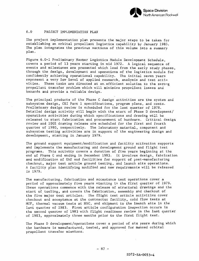
Space DivisionNorth American Rockwell
6.0 PROJECT IMPLEMENTATION PLAN
The project implementation plan presents the major steps to be taken forestablishing an orbital propellant logistics capability by January 1985.The plan integrates the previous sections of this volume into a summaryplan.
Figure 6.0-1 Preliminary Master Logistics Module Development Schedule,covers a period of 13 years starting in mid 1972. A logical sequence ofevents and milestones are presented which lead from the early study phases,through the design, development and operations of the logistics module forconfidently achieving operational capability. The initial seven yearsrepresent a very low level of applied research, analysis and test acti-vities. These tasks are directed at an.efficient solution to the zero-gpropellant transfer problem which will minimize propellant losses andhazards and provide a reliable design.
The principal products of the Phase C design activities are the system andsubsystem design, CEI Part 1 specifications, program plans, and costs.Preliminary design review is scheduled for the last quarter of 1978.Detailed design activity will begin with the start of Phase D development/operations activities during which specifications and drawing will bereleased to start fabrication and procurement of hardware. Critical designreview and 100% drawing release are scheduled for the first and fourthquarter of 1980, respectively. The laboratory material, component andsubsystem testing activities are in support of the engineering design anddevelopment, starting in January 1979.
The ground support equipment/modification and facility activation supportsand implements the manufacturing and development ground and flight testprograms. This activity covers a duration of five years beginning at theend of Phase C and ending in December 1983. It involves design, fabricationand modification of GSE and facilities for support of post-manufacturingcheckout, major test article ground testing, and launch site operations.A facility plan identifying modified and new requirements will be releasedin 1979.
The manufacturing, fabrication and acceptance test operations cover aperiod of approximately five years starting in the first quarter of 1979.These operations commence with the release of structural drawings and thestart of tooling, and covers the fabrication, assembly and checkout ofthe five major test articles. The flight test article activities covercheckout and acceptance at the contractor facility, cold flow tests atMTF, thermal vacuum tests at MSC, and shipment to the launch site in thelast quarter of 1983. First article configuration inspection occurs inthe second quarter of 1983 with flight readiness review in the last quarterof 1983, approximately three months prior to the first flight test.
The Phase D development/operations cover a period of six years during whichthe hardware is manufactured, tested, and approved for manned orbitalpropellant transfer missions.
- 87 -
SD72-SA-0053-4
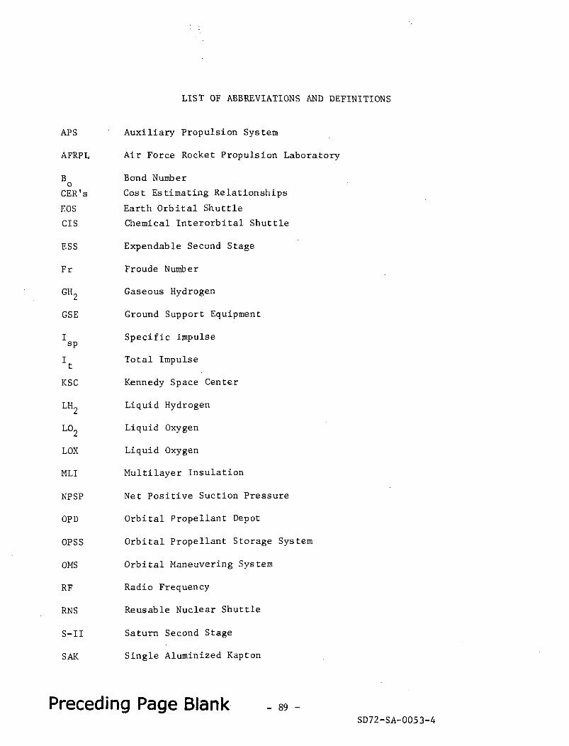
LIST OF ABBREVIATIONS AND DEFINITIONS
APS
AFRPL
Bo
CER's
EOS
CIS
ESS
Fr
GH2
GSE
sp
I
KSC
LH2
L02
LOX
MLI
NPSP
OPD
OPSS
OMS
RF
RNS
S-II
SAK
Auxiliary Propulsion System
Air Force Rocket Propulsion Laboratory
Bond Number
Cost Estimating Relationships
Earth Orbital Shuttle
Chemical Interorbital Shuttle
Expendable Second Stage
Froude Number
Gaseous Hydrogen
Ground Support Equipment
Specific Impulse
Total Impulse
Kennedy Space Center
Liquid Hydrogen
Liquid Oxygen
Liquid Oxygen
Multilayer Insulation
Net Positive Suction Pressure
Orbital Propellant Depot
Orbital Propellant Storage System
Orbital Maneuvering System
Radio Frequency
Reusable Nuclear Shuttle
Saturn Second Stage
Single Aluminized Kapton
Preceding Page Blank - 89 -SD72-SA-0053-4
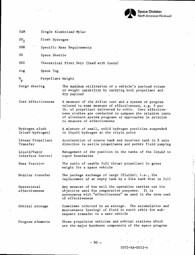
Space DivisionNorth American Rockwell
SAM
SH2
SMR
SS
TFU
tug
W
Single Aluminized Mylar
Slush Hydrogen
Specific Mass Requirements
Space Shuttle
Theoretical First Unit (Used with Costs)
Space Tug
Propellant Weight
Cargo sharing
Cost effectiveness
Hydrogen slush(slush hydrogen)
Linear PropellantTransfer
Liquid/VaporInterface Control
Mass Fraction
Modular transfer
Operationaleffectiveness
Orbital storage
Program elements
The maximum utilization of a vehicle's payload volumeor weight capability by carrying both propellant anddry payload
A measure of the dollar cost and a system or programrelated to some measure of effectiveness, e.g. $ perIb. of propellant delivered to orbit. Cost effective-ness studies are conducted to compare the relative costsof alternate system programs or approaches in relationto measure of effectiveness
A mixture of small, solid hydrogen particles suspendedin liquid hydrogen at the triple point
Acceleration of source tank and receiver tank in X axisdirection to settle propellants and permit fluid pumping
Management of the position in the tanks of the liquid tovapor boundaries
The ratio of usable full thrust propellant to grossweight for a space vehicle
The package exchange of cargo (fluids); i.e., thereplacement of an empty tank by a like tank that is full
Any measure of how well the operation carries out itsobjective used for comparative purposes. It issynonymous with "effectiveness" as used in the term costof effectiveness
Sometimes referred to as storage. The accumulation andmaintenance (saving) of fluid in earth orbit for sub-sequent transfer to a user vehicle
Those propulsive vehicles and orbital stations whichare the major hardware components of the space program
- 90 -
SD72-SA-0053-4
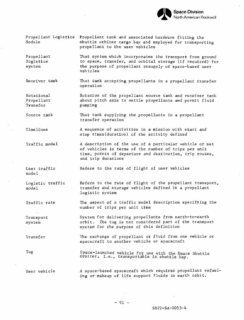
Space DivisionNorth American Rockwell
Propellant LogisticsModule
Propellantlogisticssys tern
Propellant tank and associated hardware fitting theshuttle orbiter cargo bay and employed for transportingpropellant to the user vehicles
That system which incorporates the transport from groundto space, transfer, and orbital storage (if required) forthe purpose of propellant resupply of space-based uservehicles
Receiver tank
RotationalPropellantTransfer
Source tank
Timelines
Traffic model
User trafficmodel
Logistic trafficmodel
Traffic rate
Transportsystem
Transfer
Tug
User vehicle
That tank accepting propellants in a propellant transferoperation
Rotation of the propellant source tank and receiver tankabout pitch axis to settle propellants and permit fluidpumping
That tank supplying the .propellants in a propellanttransfer operation
A sequence of activities in a mission with start andstop times(duration) of the activity defined
A description of the use of a particular vehicle or setof vehicles in terms of the number of trips per unittime, points of departure and destination, trip routes,and trip durations
Refers to the rate of flight of user vehicles
Refers to the rate of flight of the propellant transport,transfer and storage vehicles defined in a propellantlogistic system
The aspect of a traffic model description specifying thenumber of trips per unit time
System for delivering propellants from earth-to-earthorbit. The tug is not considered part of the transportsystem for the purpose of this definition
The exchange of propellant or fluid from one vehicle orspacecraft to another vehicle or spacecraft
Space-launched vehicle for use with the Space ShuttleOrbiter, i.e., transportable in shuttle bay.
A space-based spacecraft which requires propellant refuel-ing or makeup of life support fluids in earth orbit.
-91 -SD72-SA-0053-4
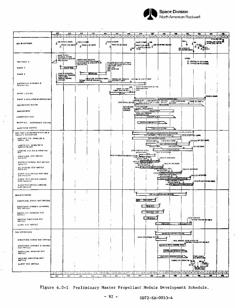
Space DivisionNorth American Rockwell
mian 1 I I « 1 1 ) 4
, ral PHASE K COM*
, PHASE A GO-AMAO
rnusiicoMn/ PHASE OO GO-
f PHASE CCOMtt rCM
iPHASE D GO-Ai SKUTTLIOI
PHI P H A S E A
PHASE «
PHASI I
S U P P O R T I N G R E S E A R C H 4TECHNKI ncv
PHASE (. D E S I G N
PHASE D DEVELOPMENTJOPERATION
UGIIISSRING DESIGN
PIOCUREMENT
l A I O R A I O R r ISSI
RIATERKIS - COMPONINIS 1CSIING
S U P S V S t E M T E S T I N G
I TRADE JIIIDIESnCIWICAl RIPOII
1 IMPllMENUHONd'.*£ PRaiMCUST
PRtltMAW f
t OPERATIONAL CONCEPTShSYSTlMlSUBSYSTli "kofVUOPMlNT I IMPlf PRELIM COS!
- START OF RrSEARCKPROPQ.LAN1 tRANSFta
- STRUCTURES- MRMM. COHTI- SYSHMS
, MISilONOBJtCTIVE!SYSHMSUBSYSTI-M
} FUNCTIONM SPfCS(- SPEC IRK
PRRIMMSIGM(COST.
O CONTtOllfD MR.KTOWSy- SUPPORTING MIlfSTOWk
CSE M B R I C A T I O N f M O O I F I C A T I O N If A C l L I T Y A C T I V A T I O N
L A U N C H C f O . HANDLINGS E R V I C I N G C S t
L A N D I N G S I T E C fO t HANDLINGCS(
STRUCHIRAI T ( S T A R T l C l E
D V N A M I C ' T H E R M A L T E S T A R T I C L EF A C I L I T Y
FL IGHT T E S T A R T I C L E P O S T M F CC / 0 F A C I L I T Y
FL IGHT T E S T ART ICLE I AUNCHS I T E F A C I L I T Y
F L I G H T T E S T A R T I C L E L A N D I N GSITE F A C I L I T Y
I ftm ' SYSIIM ISIfrtSVMIM 1)COMPICEIPAHH - | I PROUIAMP.AW
' COMPL MAKE OR BUY—. _ ' COM .
j -L... ... "hlVftnPMINTKffffitATinMtCDH SUB.AS'iY . i CDR STBl'f n'Cpi lf"« OWG , SIAfil SuSTAi
STARTjDFTAIl DiSICN^ |»THV7g^^'-"" W*"f*>'- fHIASI ^IHQRT
rfHA!SIDCOMPl
ilNITIATtlONG ryiNIMAIE RAW[LEAD PRO • nAMAT'L PROCUREMF-VT[CUKIMNT ~ ——
OFSICNCOMPl CVO 1 ACaPT TtST CUt blt,N (.DMH v»7 '"P & <*a^' 1.1 MH^ -^UO (> AttlPCSnABtMOOiUCiVIION It
|Q[SICNCOMPl^ fAB t ASSY COMPl | ^1
I CSE UB'MOPinf.ATlON J
C/OlACCffTTlSTIOWl.
f*B t ASSY COMF1 .
I J START FAB/INSn & TTST I -. f-M t*lj-'^ft"lt ICA1'"j! ,DfSICNrOMPl. ' IACII ITY Ari lVAIRD
J • Pt? w f 1WCIllTYMOOIF/CATIOWAaiVAlinN \ ' '
_..TTST ,
\i,FACILITY ACTIVATID
\"s;;™Sii,™), • j."111" •em" •r tACIIITYMODIflCATlfrACTIyATIOIl T |
R I A N U F A C T U R I N G
STQUCIURA l S T A T I C TI5T AITIC1I
S T R U C T U R A L D Y N A M I C i T H E R M A lT E S T A R I I C I E
PROPEI1«NI HAN51BR T E S TA R T I C I E
DOCKING S U B S Y S T E M I E S TAI I ICLE
(L IGHT IESI AI I ICLE
TOaiNG-fA8RICATION<l€CKOUT
IMAIU EAiiAsn I I
' I F A g t A S S Y J
I FA» t ASSY • 00 V i
I HI USSY I
Figure 6.0-1 Preliminary Master Propellant Module Development Schedule.
~ 92 - SD72-SA-0053-4