Embed Size (px)
Citation preview
Project no.: 219123
Project acronym
REALISEGRID
Project title:
REseArch, methodoLogIes and technologieS for the effective development of pan-European key GRID infrastructures to support the
achievement of a reliable, competitive and sustainable electricity supply
Instrument: Collaborative project
Thematic priority: ENERGY.2007.7.3.4 Analysis and scenarios of energy infrastructure evolution
Start date of project: 01 September 2008 Duration: 30 months
D1.2.1 Improving network controllability by Flexible Alternating Current
Transmission System (FACTS) and by High Voltage Direct Current (HVDC) transmission systems
Revision: Final
Submission date: 2010-03-08
Organisation name of lead contractor for this deliverable: Technical University Dortmund (TUDo)
Dissemination Level
PU Public PP Restricted to other programme participants (including the Commission Services) RE Restricted to a group specified by the consortium (including the Commission Services) X CO Confidential , only for members of the consortium (including the Commission Services)

D1.2.1 Improving network controllability by FACTS and by HVDC transmission systems Page 3
Deliverable number: D1.2.1 Deliverable title: Improving network controllability by Flexible Alternating Current Transmission System
(FACTS) and by High Voltage Direct Current (HVDC) transmission systems Work package: WP1: Performances and costs of innovative grid technologies Lead contractor: Technical University Dortmund
Quality Assurance Status of deliverable
Action By Date Verified (WP-leader) Athanase Vaféas, TECHNOFI 2010-03-08 Approved (Coordinator) Gianluigi Migliavacca, ERSE (former CESI RICERCA) 2010-03-08
Submitted Author(s)
Name Organisation E-mail Sven Rüberg TU Dortmund [email protected] Helder Ferreira JRC – Institute for Energy [email protected] Angelo L’Abbate JRC – Institute for Energy, now with ERSE
(former CESI RICERCA) [email protected]
Ulf Häger TU Dortmund [email protected] Gianluca Fulli JRC – Institute for Energy [email protected] Yong Li TU Dortmund [email protected] Johannes Schwippe TU Dortmund [email protected]
Abstract The present report aims at describing the main features of two key families of advanced power technologies, which may play a crucial role in the further development of the European transmission system: Flexible Alternating Current Transmission System (FACTS) and High Voltage Direct Current (HVDC) transmission. These power electronics-based devices offer the possibility to increase transmission network capacity as well as flexibility and generally enhance system reliability, security, and controllability with a limited environmental impact. FACTS and HVDC may provide transmission planners with effective solutions to several problems they encounter nowadays in planning their grids. After illustrating the technical characteristics of the different FACTS and HVDC technologies, crucial economic and environmental figures are provided. These elements are needed for a techno-economic and also environmental assessment of the impact of such devices on the system. Also planning guidelines for general and some specific application cases are described in this report. The final goal is to provide the European TSOs with the key elements of FACTS and HVDC and with guidelines to support their decision-making to select the most sound expansion alternative, while including FACTS and HVDC among the possible reinforcement options of modern transmission planning processes.
D1.2.1 Improving network controllability by FACTS and by HVDC transmission systems Page 4
TABLE OF CONTENTS
Page
ACRONYMS AND DEFINITIONS .............................................................................................. 7
1 EXECUTIVE SUMMARY .................................................................................................. 11
2 INTRODUCTION ................................................................................................................ 17
2.1 Objectives of this deliverable..................................................................................... 17
2.2 Expected outcome ...................................................................................................... 17
2.3 Approach.................................................................................................................... 19
3 TECHNOLOGICAL OVERVIEW OF FLEXIBLE ALTERNATING CURRENT TRANSMISSION SYSTEM (FACTS) ................................................................................ 20
3.1 Brief historical background........................................................................................ 20
3.2 Description of technological features......................................................................... 22
3.2.1 Shunt controllers ............................................................................................ 25
3.2.2 Series Controllers ........................................................................................... 30
3.2.3 Combined controllers ..................................................................................... 35
3.2.4 Reliability and availability of FACTS devices .............................................. 42
3.2.5 Summary of main FACTS features................................................................ 43
4 TECHNOLOGICAL OVERVIEW OF HIGH VOLTAGE DIRECT CURRENT (HVDC) TRANSMISSION ................................................................................................................. 44
4.1 Brief historical background........................................................................................ 44
4.2 Description of technological features......................................................................... 45
4.2.1 Line-commutated CSC-HVDC ...................................................................... 46
4.2.2 Self-commutating VSC-HVDC...................................................................... 49
4.2.3 Reliability and availability of HVDC transmission links............................... 52
4.2.4 Summary of main HVDC features ................................................................. 52
D1.2.1 Improving network controllability by FACTS and by HVDC transmission systems Page 5
4.2.5 Integration of HVDC into synchronously operated power grids ................... 53
4.2.6 Multi-terminal HVDC (MTDC)..................................................................... 55
5 ECONOMIC AND ENVIRONMENTAL ASPECTS.......................................................... 59
5.1 General assumptions .................................................................................................. 59
5.2 Economic aspects of FACTS ..................................................................................... 59
5.3 Economic aspects of HVDC ...................................................................................... 62
5.4 Environmental impact of FACTS .............................................................................. 65
5.5 Environmental impact of HVDC ............................................................................... 66
6 PLANNING GUIDELINES FOR THE INTEGRATION OF FACTS AND HVDC INTO MESHED NETWORKS....................................................................................................... 69
6.1 Bottom-up approach................................................................................................... 69
6.1.1 Potential of FACTS towards power system development ............................. 69
6.1.2 Potential of HVDC towards power system development............................... 73
6.2 Top-down approach ................................................................................................... 75
6.2.1 Overview on transmission expansion planning.............................................. 77
6.2.2 Planning guidelines for transmission congestion relief and capacity enhancement................................................................................................... 77
6.2.3 Planning guidelines for coupling of asynchronous networks......................... 83
6.2.4 Planning guidelines for the connection of offshore wind farms .................... 84
6.3 Examples of FACTS and HVDC applications........................................................... 86
6.3.1 Cost-benefit analysis of transmission investments......................................... 86
6.3.2 Cost-benefit analysis of FACTS .................................................................... 87
6.3.3 Cost-benefit analysis of HVDC...................................................................... 88
6.3.4 Practical FACTS and HVDC applications in Europe .................................... 88
7 CONCLUSIONS................................................................................................................. 100
D1.2.1 Improving network controllability by FACTS and by HVDC transmission systems Page 6
8 REFERENCES.................................................................................................................... 105
D1.2.1 Improving network controllability by FACTS and by HVDC transmission systems Page 7
ACRONYMS AND DEFINITIONS
AC: Alternating Current AEP: American Electric Power ASC: Advanced Series Compensator ASVC: Advanced Static VAR Compensator B2B: Back-to-back BPA: Bonneville Power Administration CSC: Current Source Converter DC: Direct Current DFC: Dynamic Flow Controller DTR: Dynamic Thermal Rating EC: European Commission EMI: Electromagnetic Interference ENTSO-E: European Network of Transmission System Operators for Electricity EPRI: Electric Power Research Institute ESCR: Effective Short Circuit Ratio ETO: Emitter Turn-Off (Thyristor) EU: European Union FACTS: Flexible Alternating Current Transmission System FSC: Fixed Series Capacitor GTO: Gate Turn-Off (Thyristor) HTC: High Temperature Conductor
D1.2.1 Improving network controllability by FACTS and by HVDC transmission systems Page 8
HVAC: High Voltage Alternating Current HVDC: High Voltage Direct Current IGBT: Insulated Gate Bipolar Transistor IGCT: Integrated Gate Commutated Thyristor IPC: Interphase Power Controller IPFC: Interline Power Flow Controller LCC: Line Commutated Converter MCT: MOS Controlled Thyristor MOS: Metal Oxide Semiconductor MOV: Metal Oxide Varistor MSC: Mechanically Switched Capacitor MTDC: Multi-terminal DC NYPA: New York Power Authority OHL: Overhead Line PAR: Phase Angle Regulator PST: Phase Shifting Transformer PWM: Pulse Width Modulation RES: Renewable Energy Source RSVC: Relocatable Static VAR Compensator SC: Series Compensator SSC: Static Synchronous Compensator SSSC: Static Synchronous Series Compensator
D1.2.1 Improving network controllability by FACTS and by HVDC transmission systems Page 9
STATCOM: STATic Synchronous COMpensator STATCON: Static Condenser SVC: Static VAR Compensator SVG: Static VAR Generator SVS: Synchronous Voltage Source TCBR: Thyristor Controlled Braking Resistor TCPAR: Thyristor Controlled Phase Angle Regulator TCPST: Thyristor Controlled Phase Shifting Transformer TCQBT: Thyristor Controlled Quadrature Boosting Transformer TCR: Thyristor Controlled Reactor TCSC: Thyristor Controlled Series Capacitor TCVL: Thyristor Controlled Voltage Limiter TCVR: Thyristor Controlled Voltage Regulator TSO: Transmission System Operator TSSC: Thyristor Switched Series Capacitor TVA: Tennessee Valley Authority UK: United Kingdom UPFC: Unified Power Flow Controller USA: United States of America VSC: Voltage Source Converter WAPA: Western Area Power Administration XLPE: Cross Linked Polyethylene Insulation

D1.2.1 Improving network controllability by FACTS and by HVDC transmission systems Page 11
1 EXECUTIVE SUMMARY
In the European Union (EU), issues concerning security of energy supply, electricity market restructuring and increasing environmental constraints represent key drivers for new trends which may have significant impact on the design and the operation of the electric power system. This is particularly true for the European electricity grids, which are on the critical path to meet the EU’s climate change and energy policy objectives for 2020 and beyond. Concerning the European transmission network, the challenge will be the integration of very large amounts of variable renewable energy sources (RES), especially wind and solar, into the power system, while keeping its security and reliability levels. To this scope, a more flexible transmission grid would be then needed. Furthermore, the ongoing energy market liberalization process in Europe is leading to the development and operation of regional electricity markets, facilitating cross-border power transactions; the resulting steady increase of inter-area power exchanges is generally causing a higher amount of congestion affecting electricity transmission networks. To address such issues, the solution of increasing the power transmission capacity, traditionally realized by means of High Voltage Alternating Current (HVAC) infrastructures, is nowadays seriously hampered by economic, social and environmental constraints. Thus, the need for evolution in the design and operation of transmission networks emerges in Europe: this will require a re-engineering process. Among the different measures to support such a process, a crucial role will be played by innovative power transmission technologies to be integrated into the existing power system. In this context, the present report focuses on the main features of two categories of advanced transmission technologies: FACTS (Flexible Alternating Current Transmission System) and HVDC (High Voltage Direct Current). These devices may play a crucial role in the development of the future European transmission system: they represent, in fact, innovative power transmission technologies, which may provide European Transmission System Operators (TSOs) with effective solutions to the several issues they encounter nowadays in the grid planning processes. The FACTS technology is not represented by a single high-power controlling device, but rather by a collection of controllers: these, singularly or in coordination with others, give the possibility to fast control one or more of the interdependent parameters that influence the operation of transmission networks. These parameters include e.g. the line series impedance, the nodal voltage amplitude, the nodal voltage angular difference, the shunt impedance, and the line current. The design of the different schemes and configurations of FACTS devices is based on the combination of traditional power system components (such as transformers, reactors, switches, and capacitors) with power electronics elements (such as various types of transistors and thyristors). The development of FACTS controllers is strictly related to the progress made by the power electronics. Over the last years, the current rating of thyristors has evolved into higher nominal values making power electronics capable of high power applications of tens, hundreds and thousands of MW. FACTS devices, thanks to their speed and flexibility, are able to provide the transmission system with several advantages such as: transmission capacity enhancement, power flow control, transient stability improvement, power oscillation damping, voltage stability and control. Depending on the
D1.2.1 Improving network controllability by FACTS and by HVDC transmission systems Page 12
type and rating of the selected device and on the specific voltage level and local network conditions, a transmission capacity enhancement of up to 40-50% may be achieved by installing a FACTS element. In comparison to traditional mechanically-driven devices, FACTS controllers are also not subject to wear and require a lower maintenance. In general, FACTS devices can be traditionally classified according to their connection, as:
• Shunt controllers. Among the shunt controllers the main devices are the Static VAR Compensator (SVC) and the Static Synchronous Compensator (STATCOM);
• Series controllers. The series controllers category includes devices like the Thyristor Controlled Series Capacitor (TCSC) and the Static Synchronous Series Compensator (SSSC);
• Combined controllers. Elements such as the Thyristor Controlled Phase Shifting Transformer (TCPST), the Interline Power Flow Controller (IPFC), the Dynamic Flow Controller (DFC) and the Unified Power Flow Controller (UPFC) belong to this third category of FACTS.
FACTS devices can be also classified according to the power electronics technology used for the converters as:
• Thyristor-based controllers. This category includes the FACTS devices based on thyristors, namely the SVC, the TCSC, the TCPST and the DFC;
• Voltage source-based controllers. These devices are based on more advanced technology like Gate Turn-Off (GTO) thyristors, Integrated Gate Commutated Thyristors (IGCT) and Insulated Gate Bipolar Transistors (IGBT). This group includes the STATCOM, the SSSC, the IPFC and the UPFC.
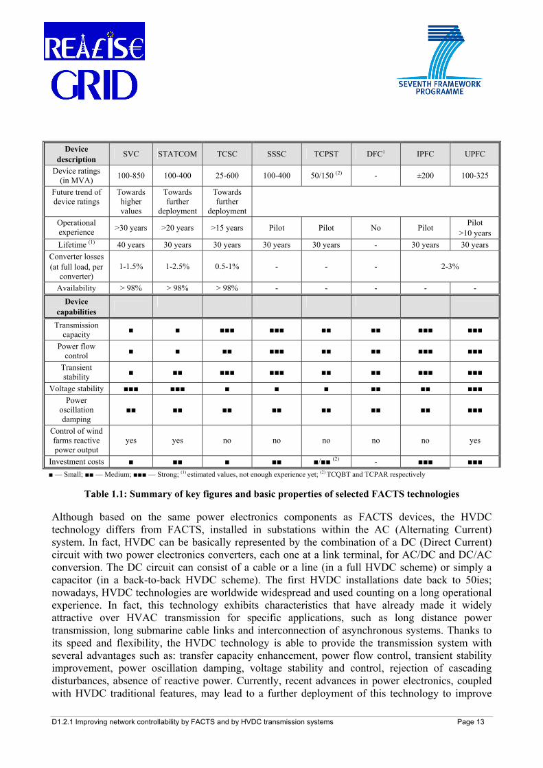
The voltage source-based devices are the most advanced ones of the FACTS family, offering the possibility for a smoother, faster control of active and/or reactive power flow and/or nodal voltage amplitude independently of the current. The most complete and versatile (and costly) FACTS device is the UPFC, able to independently and simultaneously control active power flow, reactive power flow and nodal voltage magnitude. The UPFC has been so far applied only in three installations worldwide (outside Europe), while the most widespread FACTS is the SVC, mostly suitable for voltage control and oscillation damping. Other more deployed devices are the STATCOM and the TCSC.
Table 1.1 provides an outlook of the main features of the most promising FACTS devices.
D1.2.1 Improving network controllability by FACTS and by HVDC transmission systems Page 13
Device description
SVC STATCOM TCSC SSSC TCPST DFC1 IPFC UPFC
Device ratings (in MVA) 100-850 100-400 25-600 100-400 50/150 (2) - ±200 100-325
Future trend of device ratings
Towards higher values
Towards further
deployment
Towards further
deployment
Operational experience >30 years >20 years >15 years Pilot Pilot No Pilot Pilot
>10 years Lifetime (1) 40 years 30 years 30 years 30 years 30 years - 30 years 30 years
Converter losses (at full load, per
converter) 1-1.5% 1-2.5% 0.5-1% - - - 2-3%
Availability > 98% > 98% > 98% - - - - -
Device capabilities
Transmission capacity ■ ■ ■■■ ■■■ ■■ ■■ ■■■ ■■■
Power flow control ■ ■ ■■ ■■■ ■■ ■■ ■■■ ■■■
Transient stability ■ ■■ ■■■ ■■■ ■■ ■■ ■■■ ■■■
Voltage stability ■■■ ■■■ ■ ■ ■ ■■ ■■ ■■■ Power
oscillation damping
■■ ■■ ■■ ■■ ■■ ■■ ■■ ■■■
Control of wind farms reactive power output
yes yes no no no no no yes
Investment costs ■ ■■ ■ ■■ ■/■■ (2) - ■■■ ■■■ ■ — Small; ■■ — Medium; ■■■ — Strong; (1) estimated values, not enough experience yet; (2) TCQBT and TCPAR respectively
Table 1.1: Summary of key figures and basic properties of selected FACTS technologies
Although based on the same power electronics components as FACTS devices, the HVDC technology differs from FACTS, installed in substations within the AC (Alternating Current) system. In fact, HVDC can be basically represented by the combination of a DC (Direct Current) circuit with two power electronics converters, each one at a link terminal, for AC/DC and DC/AC conversion. The DC circuit can consist of a cable or a line (in a full HVDC scheme) or simply a capacitor (in a back-to-back HVDC scheme). The first HVDC installations date back to 50ies; nowadays, HVDC technologies are worldwide widespread and used counting on a long operational experience. In fact, this technology exhibits characteristics that have already made it widely attractive over HVAC transmission for specific applications, such as long distance power transmission, long submarine cable links and interconnection of asynchronous systems. Thanks to its speed and flexibility, the HVDC technology is able to provide the transmission system with several advantages such as: transfer capacity enhancement, power flow control, transient stability improvement, power oscillation damping, voltage stability and control, rejection of cascading disturbances, absence of reactive power. Currently, recent advances in power electronics, coupled with HVDC traditional features, may lead to a further deployment of this technology to improve
D1.2.1 Improving network controllability by FACTS and by HVDC transmission systems Page 14
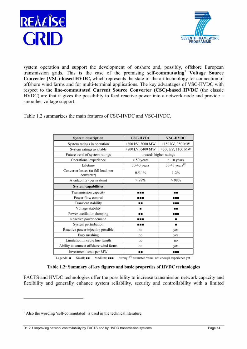
system operation and support the development of onshore and, possibly, offshore European transmission grids. This is the case of the promising self-commutating1 Voltage Source Converter (VSC)-based HVDC, which represents the state-of-the-art technology for connection of offshore wind farms and for multi-terminal applications. The key advantages of VSC-HVDC with respect to the line-commutated Current Source Converter (CSC)-based HVDC (the classic HVDC) are that it gives the possibility to feed reactive power into a network node and provide a smoother voltage support.
Table 1.2 summarizes the main features of CSC-HVDC and VSC-HVDC.
System description CSC-HVDC VSC-HVDC System ratings in operation ±800 kV, 3000 MW ±150 kV, 350 MW
System ratings available ±800 kV, 6400 MW ±300 kV, 1100 MW Future trend of system ratings towards higher ratings
Operational experience > 50 years ~ 10 years Lifetime 30-40 years 30-40 years(1)
Converter losses (at full load, per converter) 0.5-1% 1-2%
Availability (per system) > 98% > 98%
System capabilities Transmission capacity ■■■ ■■
Power flow control ■■■ ■■■ Transient stability ■■ ■■■ Voltage stability ■ ■■
Power oscillation damping ■■ ■■■ Reactive power demand ■■■ ■
System perturbation ■■■ ■ Reactive power injection possible no yes
Easy meshing no yes Limitation in cable line length no no
Ability to connect offshore wind farms no yes Investment costs per MW ■■ ■■■
Legenda: ■ — Small; ■■ — Medium; ■■■ — Strong; (1) estimated value, not enough experience yet
Table 1.2: Summary of key figures and basic properties of HVDC technologies
FACTS and HVDC technologies offer the possibility to increase transmission network capacity and flexibility and generally enhance system reliability, security and controllability with a limited
1 Also the wording ‘self-commutated’ is used in the technical literature.
D1.2.1 Improving network controllability by FACTS and by HVDC transmission systems Page 15
environmental impact. These properties are especially important in a deregulated environment, where, in presence of more frequent and severe corridor congestions, fast-reacting FACTS and HVDC elements can efficiently avoid or relieve network constraints. This can then lead to a reduced need for building new HVAC lines with consequent environmental and economic benefits. Moreover, the deployment of FACTS and HVDC can allow a further, smoother integration of variable RES power plants into the European power system. Notwithstanding the several benefits which may be provided by these advanced devices, features such as technology costs and complexity may still represent barriers hindering the utilization of FACTS and HVDC devices to address European transmission issues. In this context, it is crucial to provide economic figures, as they are key elements in the ranking of different expansion options within the transmission planning process. In the report, a dedicated section specifically addresses the costs of FACTS and HVDC technologies. This investigation takes into account the costs dependencies on several parameters and includes also a comparison with other conventional HVAC devices. As the environmental fitting of an electrical power transmission system is of increasing importance, the environmental features of FACTS and HVDC are addressed as well. It is shown that the environmental impact of these technologies can be much more limited with respect to conventional HVAC devices. The above elements are then needed for a techno-economic and also environmental assessment of the impact of such devices on the system and serve as a support to transmission planners in the decision-making process of the most sound expansion alternative(s). Considering the main features and abilities of FACTS and HVDC, planning process guidelines are also introduced to be applied for general and some specific application cases. There are two possible ways to include FACTS and HVDC in the current transmission planning practice, as carried out by network planners: by a bottom-up approach and by a top-down approach. The bottom-up approach focuses firstly on the advantages and disadvantages of FACTS and HVDC transmission systems, the effects they can have on the power system operation and the aspects that need to be taken into account during the planning stage of a network expansion process. The top-down approach focuses firstly on a specific transmission issue, then on the possible different conventional and advanced solutions, and finally on the criteria that need to be followed to rank the alternative options. Three typical issues that European transmission network planners may be frequently confronted with in the future are addressed more in details: the need to increase transmission capacity within a section of the power grid, the coupling of asynchronously operated networks, and the connection of offshore-located wind parks to the main grid. Schematic flow diagrams, which can offer a support to select a list of possible technical solutions to one of the above stated issues (namely, the need to increase transmission capacity), are also presented. The provided list of possible technical solutions needs to be then further proved by network studies taking into account the actual grid configuration; in this frame, the different technological, economic and environmental criteria to address each specific problem have to be taken into due account. These guidelines provide general schemes and measures, displaying the potential role of FACTS and HVDC while including these advanced technologies among the possible reinforcement options of the transmission expansion planning process. Some practical examples of potential applications of FACTS and HVDC in the European power system are also reported.
D1.2.1 Improving network controllability by FACTS and by HVDC transmission systems Page 16
The final goal is to provide the European TSOs with the key elements of FACTS and HVDC and with guidelines for supporting their decision-making, towards the inclusion of FACTS and HVDC among the possible reinforcement options of modern transmission expansion planning processes.
D1.2.1 Improving network controllability by FACTS and by HVDC transmission systems Page 17
2 INTRODUCTION
2.1 Objectives of this deliverable The present report aims at describing the main features of two key families of advanced power technologies, which may play a crucial role in the further development of the European transmission system: Flexible Alternating Current Transmission System (FACTS) and High Voltage Direct Current (HVDC) transmission. These power electronics-based devices represent innovative power transmission technologies, which may support European transmission system operators (TSOs) in solving current system issues and planning the future grid. In fact, modern devices like FACTS and HVDC may provide transmission planners with effective solutions to the several problems they encounter nowadays.
These technologies offer the possibility to increase transmission network capacity as well as flexibility and generally enhance system reliability, security, and controllability with a limited environmental impact. These properties are particularly important in a deregulated environment, where, in presence of more frequent and severe corridor congestions, fast reacting FACTS and HVDC elements can efficiently avoid or relieve network constraints. Both HVDC transmission and FACTS devices can therefore lead to a reduced need for building new High Voltage Alternating Current (HVAC) lines with consequent environmental and economic benefits. Moreover, the deployment of FACTS and HVDC, based on their control speed, can allow a further, smoother integration of variable renewable energy sources (RES) power plants into the European power system. Also, since energy from RES more often needs to be transported from remote locations to the load centres, FACTS and HVDC transmission can help providing additional and dedicated transport capacities. Notwithstanding the several benefits which come along with these advanced devices, their technology costs and complexity may still represent barriers hindering the utilization of FACTS and HVDC devices to address European transmission issues.
In this context, the present report, after illustrating the technical characteristics of the different FACTS and HVDC technologies, provides crucial economic and environmental figures. These elements are needed for a techno-economic and also environmental assessment of the impact of such devices on the system and serve as a support for transmission planners in the decision-making process to select the most sound expansion alternative. Also planning guidelines for general and some specific application cases are described in this report.
The final goal of this report is to provide the European TSOs with the key elements of FACTS and HVDC and with guidelines to support their decision-making, while including FACTS and HVDC among the possible reinforcement options of modern transmission expansion planning processes.
2.2 Expected outcome In order to achieve the above described objectives, this report has been structured in two main parts, one dealing with the different FACTS devices and one focusing on HVDC technologies. Then, the economic and environmental features of both FACTS and HVDC are jointly addressed as well as
D1.2.1 Improving network controllability by FACTS and by HVDC transmission systems Page 18
the aspects related to the utilization of such devices for general and specific application cases (planning guidelines) are commonly treated.
Chapter 3 introduces the FACTS concept: FACTS devices are power electronics-based devices able to fast control at least one of the parameters directly impacting on transmission line power flow (series impedance, nodal voltage amplitude, nodal voltage angular difference, and so on). After briefly recalling the historical background and the power electronics developments, the different advantages provided by FACTS and related to the enhancement and improvement of transmission system utilization are considered. FACTS controllers can be classified either by connection (shunt, series, or combined) or by power electronics technology used for the converters (thyristor-based or voltage source-based). A detailed description of the technical features of the eight most important and promising FACTS devices is performed. The voltage source-based devices are the most advanced ones, offering the possibility for a smoother, faster control of active and/or reactive power flow and/or nodal voltage amplitude independently of the current.
Chapter 4 focuses on HVDC, whose first installations date back to 50ies; nowadays, HVDC technologies are worldwide widespread and used counting on a long utilization experience. In fact, this technology exhibits characteristics that have already made it widely attractive over HVAC transmission for specific applications, such as long distance power transmission, long submarine cable links and interconnection of asynchronous systems. Currently, recent advances in power electronics, coupled with traditional features of HVDC, may bring to further deploying this technology with the aim of improving operation and supporting the development of onshore and, possibly, offshore European transmission grids. This is the case of the promising self-commutating Voltage Source Converter (VSC)-based HVDC, which represents the state-of-the-art technology for connection of offshore wind farms via HVDC cables and also for multi-terminal applications. Crucial advantages of VSC-HVDC respect to the line-commutated Current Source Converter (CSC)-based HVDC (the classic HVDC) are that it gives the possibility to feed reactive power into a network node and provide a smoother voltage support. The two technologies, CSC-HVDC and VSC-HVDC, are then thoroughly examined. The different structures, characteristics, potential usages of multi-terminal HVDC are also addressed.
As economic figures are crucial elements in the ranking of different expansion options within the transmission planning process, a dedicated section of Chapter 5 specifically addresses the costs of FACTS and HVDC technologies. This investigation takes into account the costs dependencies on several parameters and includes also a comparison with other conventional HVAC devices. Chapter 5 focuses additionally on the environmental features of FACTS and HVDC as well. These elements are needed for a techno-economic and also environmental assessment of the impact of such devices on the system and serve as a support to transmission planning decisions.
Chapter 6, considering the main features and abilities of FACTS and HVDC, introduces planning process guidelines for some application cases such as transmission capacity enhancement, asynchronous systems interconnection and offshore wind farms connection. These guidelines provide general schemes and measures, displaying the potential role of FACTS and HVDC among the reinforcement options of the transmission expansion planning process in order to address issues currently faced by European TSOs.
Finally, Chapter 7 summarises the main findings and suggests a way forward.
D1.2.1 Improving network controllability by FACTS and by HVDC transmission systems Page 19
2.3 Approach The information and the data contained in this report are based on the technical and scientific literature available on FACTS and HVDC, on internal knowledge and experience as well as on responses to questionnaires from REALISEGRID project TSOs. In addition, public documents, sources, and links to projects and applications existing in Europe and worldwide have been consulted and compared in order to have a broad and consistent picture on the topics treated within this report.
The gathering and the consistency check of some critical figures (such as FACTS technologies costs) have proved to be arduous, mostly due to the scarce availability of public sources (often outdated) addressing those issues. It has to be stressed that, for the part treating general guidelines for including FACTS and HVDC into transmission planning processes, the present REALISEGRID Deliverable D1.2.1 is consistently interrelated with REALISEGRID Deliverables D3.1.1 and D3.3.1, which focus on transmission planning practices and methods for cost-benefit analyses, respectively. Furthermore, the technological part of this report is closely linked to REALISEGRID Deliverables D1.4.1 and D1.4.2, which aim at preparing a roadmap of innovative technologies for power transmission in Europe. For the part focusing on HVDC, this report completes and complements the information contained in REALISEGRID Deliverable D1.1.1 on power transmission cables. REALISEGRID Deliverables D1.2.2 and D1.3.3 will represent the follow-up of the present work, being focused on the coordinated control of FACTS and HVDC and on long AC and DC interconnections, respectively.
A steady interaction and information exchange with other project partners (TSOs, manufacturers, and other industrial stakeholders) has been fundamental to validate and consolidate the report outcomes.
D1.2.1 Improving network controllability by FACTS and by HVDC transmission systems Page 20
3 TECHNOLOGICAL OVERVIEW OF FLEXIBLE ALTERNATING CURRENT TRANSMISSION SYSTEM (FACTS)
3.1 Brief historical background The Flexible Alternating Current Transmission System (FACTS) concept is accredited to a successful definition given by Narain G. Hingorani [1] in the late 80ies when the Electric Power Research Institute (EPRI) in the United States started to investigate and develop these new devices. The FACTS technology is not represented by a single high-power controller, but rather by a collection of controllers that singularly or in coordination with others give the possibility to control one or more of the interdependent parameters that influence the operation of transmission networks. These parameters include e.g. the line series impedance, the shunt impedance, the line current, the nodal voltage amplitude, and angular difference [1][2].
The design of the different schemes and configurations of FACTS devices is based on the combination of traditional power system components (such as transformers, reactors, switches, and capacitors) with power electronics elements (such as various types of transistors and thyristors). Transistors are devices made of a semiconductor material with at least three terminals that provide for a connection to an external circuit, and are commonly used as electronically controlled amplifiers or switches. Thyristors are from the same family as transistors and are more suited to manage high power. They consist of four-layer semiconductor components which conduct when a turn-on pulse is sent to the respective gate: they are practically one-way switches and are configured in many different solutions in circuits with appropriate controls to carry out energy conversion, frequency conversion, switching, and many other applications. Over the last years, the current rating of thyristors has evolved into higher nominal values revolutionizing the power electronics industry with high power applications (termed high power electronics) of tens, hundreds and thousands of MW. The development of the semiconductor technology has made it possible to manufacture new types of thyristors, such as Gate Turn-Off (GTO) thyristors (that can also be turned off by sending a turn-off pulse to the gate), Integrated Gate Commutated Thyristors (IGCT) and Insulated Gate Bipolar Transistors (IGBT). Promising thyristors are those ones depending on Metal Oxide Semiconductor (MOS) integrated circuits, such as the MOS Controlled Thyristors (MCT). Other kinds of turn-off thyristors are expected to be studied and commercialized in the next years. The increasing progress of the thyristor-based technology has resulted firstly in the development of the High Voltage Direct Current (HVDC) transmission system as an alternative to the long-distance AC transmission. Subsequently, this proven HVDC technology served as the basis for the implementation and utilisation of FACTS controllers [1][2].
In addition to the rapidly increasing development of power electronics technology, several other driving factors related to the electricity market liberalisation are currently contributing to make FACTS utilisation necessary and profitable for power systems purposes. In a liberalised energy system, electricity tends to be considered like a 'commodity' and no longer only like a 'service'. Since it is sold and bought on a contractual basis, sellers and buyers require that they can respectively inject and withdraw the contractually scheduled energy quantities. In turn, this entails that the physical power flows should correspond to the traded power flows to avoid system congestion and/or instability. Furthermore, the electricity market liberalisation process results in the
D1.2.1 Improving network controllability by FACTS and by HVDC transmission systems Page 21
unbundling of vertically integrated utilities with consequent separation of generation, transmission and distribution functions. The grid operators, even if they no longer own the generation facilities, are however still tasked to centrally control and coordinate the production output in order to guarantee the overall system reliability in the electricity market context. Also, power flow patterns, more often dictated by market decisions, are more unpredictable and the uncertainties in generation and network planning are requiring transmission systems to be as flexible as possible. In this view, FACTS can be of useful support to grid operators in the system control. Besides, the open access to the transmission grid is determining a generally higher utilisation of transmission systems. This trend may result in more frequent network congestions. In the European power system, this occurs in particular on cross-border interconnections.
The traditional solution to address network congestion consists in increasing transmission capacity by building new lines. However, the latter nowadays is becoming more and more difficult for environmental (public concern over the impact of electromagnetic fields on health, aesthetics of transmission equipment, land value detriment), economic (new lines construction requires time, in some cases many years, and money), political (difficulty in obtaining new rights-of-way) obstacles. Therefore, an effective way to cope with this situation consists in utilising more efficiently the currently existing transmission structures. For this goal, it is necessary to free paths that are ‘occupied’ in undesired power transactions (i.e. loop flows) in order to effectively utilise these lines and to prevent possible system congestion.
Last but not least, FACTS can offer several advantages for controlling variable energy sources like wind power plants, facilitating their integration into the system.
FACTS devices are able to address all these needs making utility networks more reliable, more controllable and more efficient.
More specifically, the utilisation of FACTS devices can lead to the following key functions related to the enhancement of transmission network control:
• control of active and reactive power flows in a smooth, rapid way up to a certain level;
• reduction of undesired reactive power flows in the system and therewith of network losses;
• increase of the loading of the transmission lines to levels closer to their thermal limits without violating (n-1)2 security constraints;
• improvement of the steady state and transient stability;
• reduction of series voltage drops (in amplitude and phase) on the lines;
• limitation of voltage oscillations within the due range in presence of variation of transmission power;
2 The (n-1) security criterion is a planning rule according to which elements remaining in operation after failure of a single network element (such as a transmission line/transformer or generating unit, or in certain instances a busbar) must be capable of accommodating the change of flows in the network caused by that single failure while respecting all system constraints.
D1.2.1 Improving network controllability by FACTS and by HVDC transmission systems Page 22
• enhancement of the system damping in presence of oscillations;
• control of undesired loop flows;
• shift of the power flow from congested transmission lines to free parallel paths fast and precisely;
• control of voltage and improve power quality.
Furthermore, FACTS controllers, in comparison to mechanical devices - as transformer tap changers, shunt capacitor switches etc. that have controlled the AC power system so far - are not subject to mechanical wear: this is a great advantage of FACTS devices in addition to their high flexibility and speed.
The drawback of FACTS technology so far has been given by its costs, which are higher than those ones of mechanical devices: this factor has slowed a more widespread insertion of FACTS devices in transmission systems.
However, since all FACTS controllers are applications of similar technology, their deployment can benefit from economies of scale linked with volume production: the cost of these devices is decreasing as development of high-power electronics with the consequent technologies of scale is increasing.
3.2 Description of technological features The principle behind FACTS can be explained by a well-known formula that states (neglecting active losses) that the active power flow between two nodes (substation 1 and substation 2) along an AC transmission line (see Figure 3.1) can be expressed as
XVV
P)sin( 2,121
2,1
δ⋅= (3.1)
where: 2,1P is the active power flow between the two nodes along the line; 1V and 2V represent the respective nodal voltage magnitudes at both ends of the line; X expresses the line reactance; 2,1δ represents the voltage angular difference between the two nodes.
D1.2.1 Improving network controllability by FACTS and by HVDC transmission systems Page 23
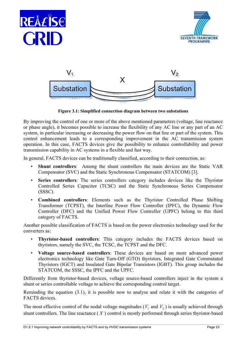
Figure 3.1: Simplified connection diagram between two substations
By improving the control of one or more of the above mentioned parameters (voltage, line reactance or phase angle), it becomes possible to increase the flexibility of any AC line or any part of an AC system, in particular increasing or decreasing the power flow on that line or part of the system. This control enhancement leads to a corresponding improvement in the AC transmission system operation. In this case, FACTS devices give the possibility to enhance controllability and power transmission capability in AC systems in a flexible and fast way.
In general, FACTS devices can be traditionally classified, according to their connection, as:
• Shunt controllers: Among the shunt controllers the main devices are the Static VAR Compensator (SVC) and the Static Synchronous Compensator (STATCOM) [3].
• Series controllers: The series controllers category includes devices like the Thyristor Controlled Series Capacitor (TCSC) and the Static Synchronous Series Compensator (SSSC).
• Combined controllers: Elements such as the Thyristor Controlled Phase Shifting Transformer (TCPST), the Interline Power Flow Controller (IPFC), the Dynamic Flow Controller (DFC) and the Unified Power Flow Controller (UPFC) belong to this third category of FACTS.
Another possible classification of FACTS is based on the power electronics technology used for the converters as:
• Thyristor-based controllers: This category includes the FACTS devices based on thyristors, namely the SVC, the TCSC, the TCPST and the DFC.
• Voltage source-based controllers: These devices are based on more advanced power electronics technology like Gate Turn-Off (GTO) thyristors, Integrated Gate Commutated Thyristors (IGCT) and Insulated Gate Bipolar Transistors (IGBT). This group includes the STATCOM, the SSSC, the IPFC and the UPFC.
Differently from thyristor-based devices, voltage source-based controllers inject in the system a shunt or series controllable voltage to achieve the corresponding control target.
Reminding the equation (3.1), it is possible now to analyse and relate it with the categories of FACTS devices.
The most effective control of the nodal voltage magnitudes ( 1V and 2V ) is usually achieved through shunt controllers. The line reactance ( X ) control is mostly performed through series thyristor-based
D1.2.1 Improving network controllability by FACTS and by HVDC transmission systems Page 24
controllers, while the same target (series power control) can be reached by series voltage source-based devices. The adjustment of the nodal voltage angular difference ( 2,1δ ) is better accomplished by combined thyristor-based devices. For an effective, contemporary control of more parameters, combined voltage source-based controllers are the most suitable ones.
The above listed devices are the most interesting and promising FACTS elements to be potentially applied in today’s networks: they are briefly described in the following subchapters. For more details on the various properties, design details and control applications of such elements the reader is referred to a very abundant literature (see [2]-[8] and the references therein reported among others)3.
3 For completeness, other FACTS devices presented in the literature, which however are not the subject of the present work, as they are still under research and development or available just for special applications, are [1]:
• NGH-SSR Damper (Hingorani’s scheme for damping of subsynchronous resonance, SSR) • TCBR (Thyristor Controlled Braking Resistor) • TCVL (Thyristor Controlled Voltage Limiter) • TCVR (Thyristor Controlled Voltage Regulator) • IPC (Interphase Power Controller)
D1.2.1 Improving network controllability by FACTS and by HVDC transmission systems Page 25
3.2.1 Shunt controllers
3.2.1.1 SVC
Shunt reactive power compensation can be obtained by means of switched or fixed capacitors and controlled or fixed reactors installed along the transmission route or at the extreme of the lines. A modern device using thyristors is the Static VAr Compensator (SVC). The role of SVCs is to adjust the amount of reactive power compensation to the actual system needs and then to control voltage [2]-[8], having also a very positive impact in dampening power oscillations. A flexible and continuous reactive power compensation is made feasible by using thyristor-switched shunt elements operating in both the capacitive and inductive regions. SVCs began to be applied in the USA (United States of America) in the 70ies, long before the concept of FACTS was formulated. The first application was the EPRI-Minnesota Power & Light and Westinghouse project commissioned in 1978 with SVCs enabling a 25% power increase along the line where they were installed. Worldwide, there is a steady increase in the number of installations. The most recent orders or installations of SVC have been carried out in Chile, Canada, USA, Mexico, South Africa and Finland [10][11][82]. In Europe, the highest amount of SVCs is concentrated in the UK (United Kingdom), while one of the latest applications concern the SVC (providing reactive power support in the range -200÷+240 MVAR) installed in Kangasala substation, Finland, in 2009 [89]. Nowadays, an estimated amount of worldwide installed SVCs (at industrial and utility level) refers to more than 800 devices for a total installed power of over 90 GVA [5][81].
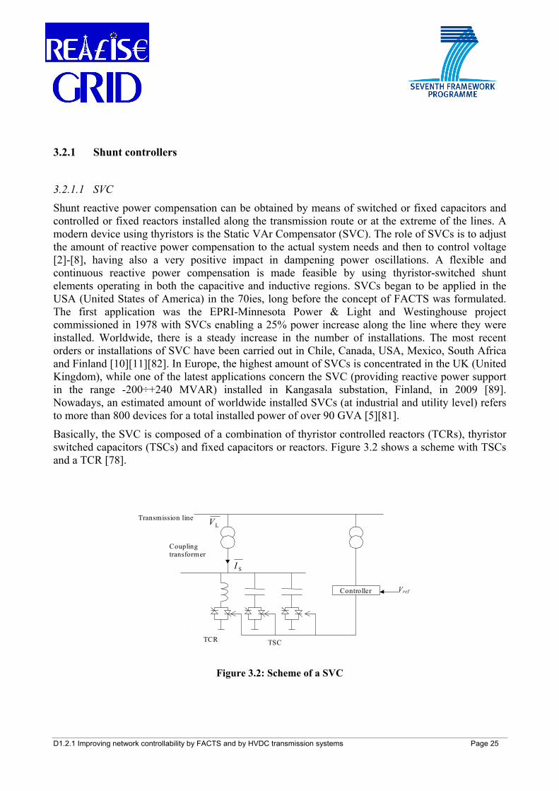
Basically, the SVC is composed of a combination of thyristor controlled reactors (TCRs), thyristor switched capacitors (TSCs) and fixed capacitors or reactors. Figure 3.2 shows a scheme with TSCs and a TCR [78].
Transmission line LV
Coupling transformer
Controller
TCR TSC
SI
Vref
Figure 3.2: Scheme of a SVC
D1.2.1 Improving network controllability by FACTS and by HVDC transmission systems Page 26
In Figure 3.2, LV represents the transmission line voltage vector, whose voltage amplitude LV is
controlled and refV is its desired value, while SI is the complex shunt current flowing through a coupling transformer into the SVC.
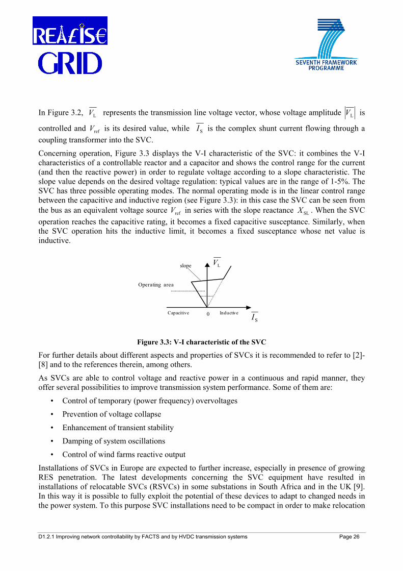
Concerning operation, Figure 3.3 displays the V-I characteristic of the SVC: it combines the V-I characteristics of a controllable reactor and a capacitor and shows the control range for the current (and then the reactive power) in order to regulate voltage according to a slope characteristic. The slope value depends on the desired voltage regulation: typical values are in the range of 1-5%. The SVC has three possible operating modes. The normal operating mode is in the linear control range between the capacitive and inductive region (see Figure 3.3): in this case the SVC can be seen from the bus as an equivalent voltage source refV in series with the slope reactance SLX . When the SVC operation reaches the capacitive rating, it becomes a fixed capacitive susceptance. Similarly, when the SVC operation hits the inductive limit, it becomes a fixed susceptance whose net value is inductive.
slope
0Capacitive Inductive
Operating area
LV
SI
Figure 3.3: V-I characteristic of the SVC
For further details about different aspects and properties of SVCs it is recommended to refer to [2]-[8] and to the references therein, among others.
As SVCs are able to control voltage and reactive power in a continuous and rapid manner, they offer several possibilities to improve transmission system performance. Some of them are:
• Control of temporary (power frequency) overvoltages
• Prevention of voltage collapse
• Enhancement of transient stability
• Damping of system oscillations
• Control of wind farms reactive output
Installations of SVCs in Europe are expected to further increase, especially in presence of growing RES penetration. The latest developments concerning the SVC equipment have resulted in installations of relocatable SVCs (RSVCs) in some substations in South Africa and in the UK [9]. In this way it is possible to fully exploit the potential of these devices to adapt to changed needs in the power system. To this purpose SVC installations need to be compact in order to make relocation
D1.2.1 Improving network controllability by FACTS and by HVDC transmission systems Page 27
possible within 3-6 months. It is evaluated that relocation might occur up to 5 times in a 40 year-operating life of a RSVC.
Table 3.1 recaps the main technical characteristics of SVCs.
SVC (Static VAR Compensator)
Type Shunt Technology Thyristor-based Power rating 100-850 MVAR
Transmission Capacity Enhancement Small impact
Power Flow Control Small impact Transient Stability Small impact Voltage Stability Strong impact Power Oscillation
Damping Medium impact
Control of wind farms output Possibility of building relocatable devices
It is the most deployed FACTS device worldwide
Table 3.1: Summary of SVC features
3.2.1.2 STATCOM
The Static Synchronous Compensator (STATCOM or SSC) represents a further development of the SVC. In literature this device is also named Static Condenser (STATCON), Static VAR Generator (SVG), GTO-SVC or Advanced SVC (ASVC) [2]-[8].
After two experimental installations of converter-based VAR compensators during the 80ies, GTOs with greatly increased rating have become available, and a ±80 MVAR installation, using 4500 V, 3000 A GTOs, has been carried out in Japan. In the USA, in 1995, a STATCOM rated for ±100 MVAR was commissioned at the Sullivan substation of the Tennessee Valley Authority (TVA) power system. In this case the GTOs are rated for 4500 V and 4000 A to control a 161 kV bus voltage. Nowadays, an estimation of the worldwide installed STATCOMs amounts to about 20 devices deployed in the USA, Japan, China and UK (only application in Europe) for a total installed power of over 1200 MVA [5][81].
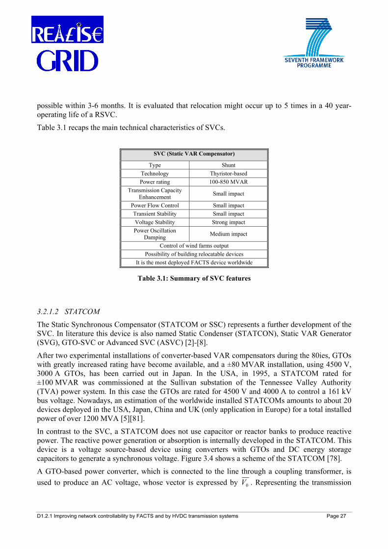
In contrast to the SVC, a STATCOM does not use capacitor or reactor banks to produce reactive power. The reactive power generation or absorption is internally developed in the STATCOM. This device is a voltage source-based device using converters with GTOs and DC energy storage capacitors to generate a synchronous voltage. Figure 3.4 shows a scheme of the STATCOM [78].
A GTO-based power converter, which is connected to the line through a coupling transformer, is used to produce an AC voltage, whose vector is expressed by 0V . Representing the transmission
D1.2.1 Improving network controllability by FACTS and by HVDC transmission systems Page 28
line voltage vector and the transformer reactance by LV and TX , respectively, then, the corresponding current vector, SI , can be obtained as:
T
0LS jX
VVI
−= (3.2)
Transmission line
Coupling transformer
P Q
Measurement signals GTO Converter
Pref Qref DC circuit C
P
Energy Source
Control
SI
LV
0V
Figure 3.4: Basic scheme of a STATCOM
When the source voltage 0V exceeds the line voltage LV , then SI is a leading reactive current
drawn from the line and the equipment behaves like a capacitor. When the source voltage 0V is
smaller than the line voltage LV , then SI is a lagging reactive current drawn from the device and the converter acts like a reactor. In practice a small amount of real power is also drawn from the line to supply the losses of the converter. The basic electronic building block for a STATCOM is a voltage-sourced converter that inverts the DC voltage at its input terminals into a three-phase set of AC output voltages [78].
A STATCOM uses many such converters, appropriately phase shifted, with their outputs combined electro-magnetically to produce a nearly sinusoidal resultant waveform. For transmission line applications, a pulse number of 24 or higher (six times the number of basic converters used) is required to achieve adequate waveform quality without passive filters. Reference signals refQ and
refP define the amplitude and the phase angle of the generated output voltage and thereby the reactive and active power exchange between the solid-state voltage source and the AC system. The reactive and active power, generated or absorbed by the STATCOM, can be controlled
D1.2.1 Improving network controllability by FACTS and by HVDC transmission systems Page 29
independently of each other, and every combination of real power generation and absorption with reactive power generation and absorption is possible. The real power that the synchronous voltage source exchanges at its AC terminals with the AC system must be supplied to or absorbed from its DC terminals by the energy storage device. Instead, the reactive power exchanged is internally generated by the voltage source, and the DC energy storage device plays no role in it [2]-[8].
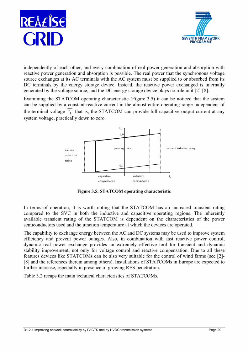
Examining the STATCOM operating characteristic (Figure 3.5) it can be noticed that the system can be supplied by a constant reactive current in the almost entire operating range independent of the terminal voltage LV that is, the STATCOM can provide full capacitive output current at any system voltage, practically down to zero.
transient inductive ratingoperating areatransient
capacitive
rating
1.0
0.1
capacitive inductive
compensation compensation
LV
SI
Figure 3.5: STATCOM operating characteristic
In terms of operation, it is worth noting that the STATCOM has an increased transient rating compared to the SVC in both the inductive and capacitive operating regions. The inherently available transient rating of the STATCOM is dependent on the characteristics of the power semiconductors used and the junction temperature at which the devices are operated.
The capability to exchange energy between the AC and DC systems may be used to improve system efficiency and prevent power outages. Also, in combination with fast reactive power control, dynamic real power exchange provides an extremely effective tool for transient and dynamic stability improvement, not only for voltage control and reactive compensation. Due to all these features devices like STATCOMs can be also very suitable for the control of wind farms (see [2]-[8] and the references therein among others). Installations of STATCOMs in Europe are expected to further increase, especially in presence of growing RES penetration.
Table 3.2 recaps the main technical characteristics of STATCOMs.
D1.2.1 Improving network controllability by FACTS and by HVDC transmission systems Page 30
STATCOM (Static Synchronous Compensator) Type Shunt
Technology VSC-based Power rating 100-400 MVAR
Transmission Capacity Enhancement Small impact
Power Flow Control Small impact Transient Stability Medium impact Voltage Stability Strong impact Power Oscillation
Damping Medium impact
Control of wind farms output
Table 3.2: Summary of STATCOM features
3.2.2 Series Controllers The impact of series elements on the control of active power flow is much more relevant compared to the one by shunt elements. The series elements are also more effective in power oscillation damping and transient stability improvement, which can be achieved by modulation of active power, while for voltage control they have a very small influence.
3.2.2.1 TCSC
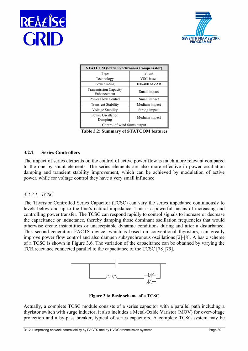
The Thyristor Controlled Series Capacitor (TCSC) can vary the series impedance continuously to levels below and up to the line’s natural impedance. This is a powerful means of increasing and controlling power transfer. The TCSC can respond rapidly to control signals to increase or decrease the capacitance or inductance, thereby damping those dominant oscillation frequencies that would otherwise create instabilities or unacceptable dynamic conditions during and after a disturbance. This second-generation FACTS device, which is based on conventional thyristors, can greatly improve power flow control and also dampen subsynchronous oscillations [2]-[8]. A basic scheme of a TCSC is shown in Figure 3.6. The variation of the capacitance can be obtained by varying the TCR reactance connected parallel to the capacitance of the TCSC [78][79].
Figure 3.6: Basic scheme of a TCSC
Actually, a complete TCSC module consists of a series capacitor with a parallel path including a thyristor switch with surge inductor; it also includes a Metal-Oxide Varistor (MOV) for overvoltage protection and a by-pass breaker, typical of series capacitors. A complete TCSC system may be
D1.2.1 Improving network controllability by FACTS and by HVDC transmission systems Page 31
comprised of several such modules in series and be a part of an overall project to improve power system performance together with a conventional series capacitor bank.
In 1991 a multi-segment, mechanically-switched series compensation system was installed by the American Electric Power (AEP) at its Kanawha River substation, with one phase of one segment augmented with a thyristor switch. A single-module TCSC was built for the Western Area Power Administration (WAPA) and put in operation at Kayenta substation, in 1992. This system is located at the mid-point of a 200-mile, 230 kV line and increases power transfer on the line by 100 MW. A complete multi-module TCSC was installed on the Slatt substation of the Bonneville Power Administration (BPA) in 1993. It is interesting to note that a recent application of TCSCs has been carried out in Brazil, where a TCSC is used in combination with 5 conventional series capacitors on a 1017 km-long 500 kV transmission system. In this application (operating since 1999) the TCSC system is utilized for damping and transient stability enhancements. The newest applications have been carried out in India and in China [10][11]. Nowadays, an estimation of worldwide installed TCSCs amounts to 10 devices (of which only one in Europe, at Stöde substation in Sweden, for subsynchronous resonance mitigation) for a total installed power of 2000 MVA ca. [5][10].
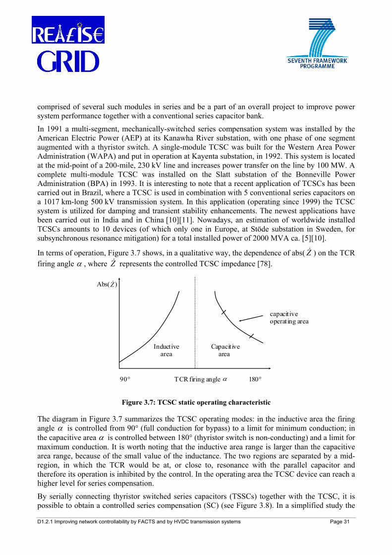
In terms of operation, Figure 3.7 shows, in a qualitative way, the dependence of abs( Z& ) on the TCR firing angle α , where Z& represents the controlled TCSC impedance [78].
Abs( )
capacitive operating area
Inductive Capacitive area area
90° TCR firing angle 180°α
Z&
Figure 3.7: TCSC static operating characteristic
The diagram in Figure 3.7 summarizes the TCSC operating modes: in the inductive area the firing angle α is controlled from 90° (full conduction for bypass) to a limit for minimum conduction; in the capacitive area α is controlled between 180° (thyristor switch is non-conducting) and a limit for maximum conduction. It is worth noting that the inductive area range is larger than the capacitive area range, because of the small value of the inductance. The two regions are separated by a mid-region, in which the TCR would be at, or close to, resonance with the parallel capacitor and therefore its operation is inhibited by the control. In the operating area the TCSC device can reach a higher level for series compensation.
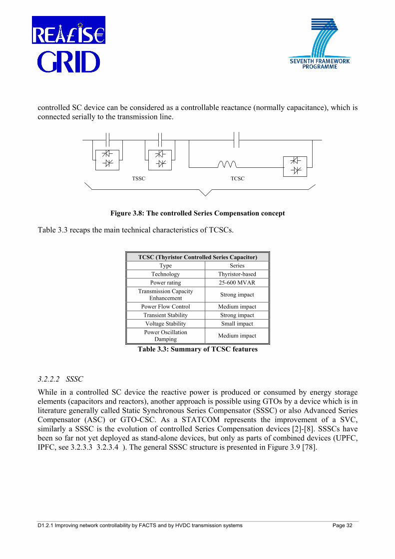
By serially connecting thyristor switched series capacitors (TSSCs) together with the TCSC, it is possible to obtain a controlled series compensation (SC) (see Figure 3.8). In a simplified study the
D1.2.1 Improving network controllability by FACTS and by HVDC transmission systems Page 32
controlled SC device can be considered as a controllable reactance (normally capacitance), which is connected serially to the transmission line.
TSSC TCSC
Figure 3.8: The controlled Series Compensation concept
Table 3.3 recaps the main technical characteristics of TCSCs.
TCSC (Thyristor Controlled Series Capacitor) Type Series
Technology Thyristor-based Power rating 25-600 MVAR
Transmission Capacity Enhancement Strong impact
Power Flow Control Medium impact Transient Stability Strong impact Voltage Stability Small impact Power Oscillation
Damping Medium impact
Table 3.3: Summary of TCSC features
3.2.2.2 SSSC
While in a controlled SC device the reactive power is produced or consumed by energy storage elements (capacitors and reactors), another approach is possible using GTOs by a device which is in literature generally called Static Synchronous Series Compensator (SSSC) or also Advanced Series Compensator (ASC) or GTO-CSC. As a STATCOM represents the improvement of a SVC, similarly a SSSC is the evolution of controlled Series Compensation devices [2]-[8]. SSSCs have been so far not yet deployed as stand-alone devices, but only as parts of combined devices (UPFC, IPFC, see 3.2.3.3 3.2.3.4 ). The general SSSC structure is presented in Figure 3.9 [78].
D1.2.1 Improving network controllability by FACTS and by HVDC transmission systems Page 33
Vc1 Vc2 Coupling transformer
P Q Measurement signals
GTO Converter
Pref Qref C
DC + - circuit P
Energy Source
Control
T V I
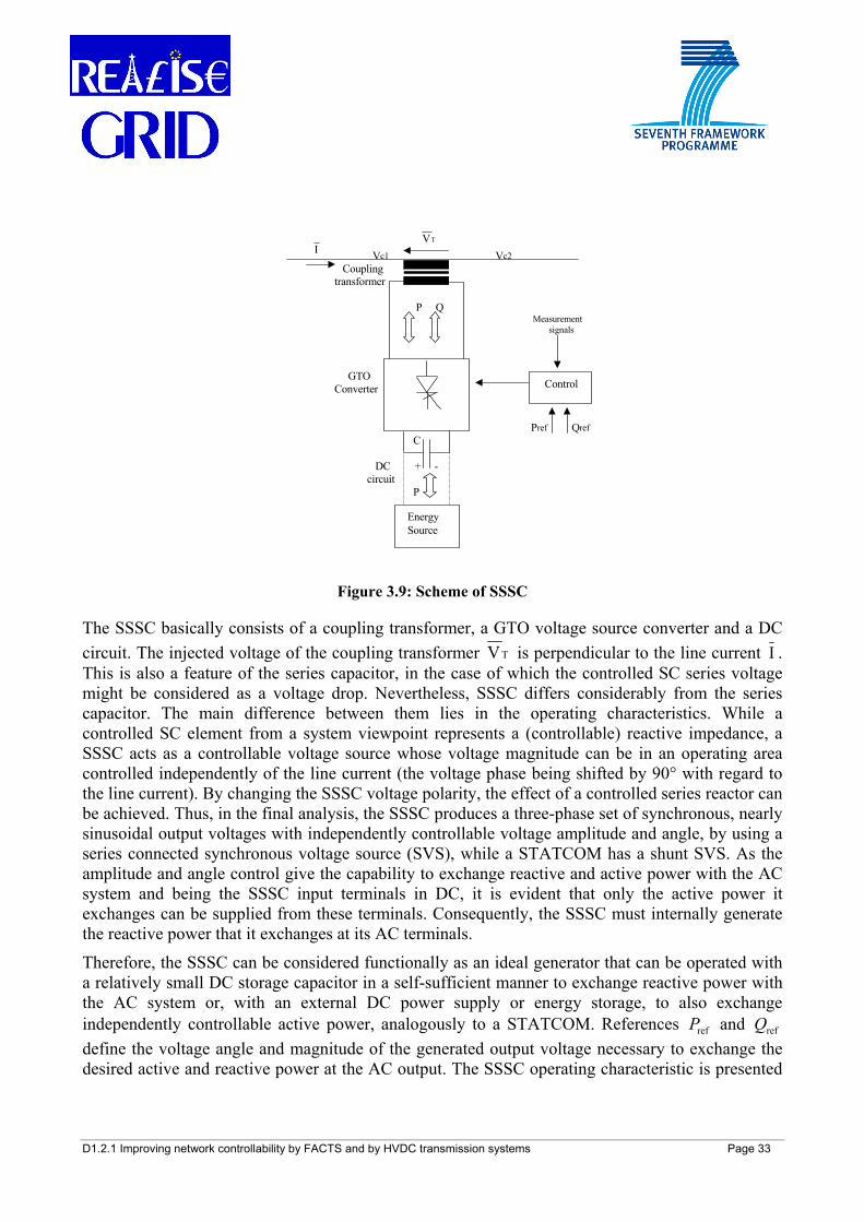
Figure 3.9: Scheme of SSSC
The SSSC basically consists of a coupling transformer, a GTO voltage source converter and a DC circuit. The injected voltage of the coupling transformer T V is perpendicular to the line current I . This is also a feature of the series capacitor, in the case of which the controlled SC series voltage might be considered as a voltage drop. Nevertheless, SSSC differs considerably from the series capacitor. The main difference between them lies in the operating characteristics. While a controlled SC element from a system viewpoint represents a (controllable) reactive impedance, a SSSC acts as a controllable voltage source whose voltage magnitude can be in an operating area controlled independently of the line current (the voltage phase being shifted by 90° with regard to the line current). By changing the SSSC voltage polarity, the effect of a controlled series reactor can be achieved. Thus, in the final analysis, the SSSC produces a three-phase set of synchronous, nearly sinusoidal output voltages with independently controllable voltage amplitude and angle, by using a series connected synchronous voltage source (SVS), while a STATCOM has a shunt SVS. As the amplitude and angle control give the capability to exchange reactive and active power with the AC system and being the SSSC input terminals in DC, it is evident that only the active power it exchanges can be supplied from these terminals. Consequently, the SSSC must internally generate the reactive power that it exchanges at its AC terminals.
Therefore, the SSSC can be considered functionally as an ideal generator that can be operated with a relatively small DC storage capacitor in a self-sufficient manner to exchange reactive power with the AC system or, with an external DC power supply or energy storage, to also exchange independently controllable active power, analogously to a STATCOM. References refP and refQ define the voltage angle and magnitude of the generated output voltage necessary to exchange the desired active and reactive power at the AC output. The SSSC operating characteristic is presented
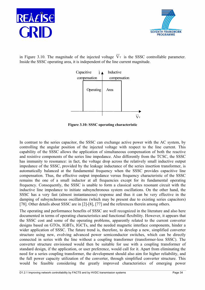
D1.2.1 Improving network controllability by FACTS and by HVDC transmission systems Page 34
in Figure 3.10. The magnitude of the injected voltage T V is the SSSC controllable parameter. Inside the SSSC operating area, it is independent of the line current magnitude.
Capacitive Inductive compensation compensation
Operating Area
TV
I
Figure 3.10: SSSC operating characteristic
In contrast to the series capacitor, the SSSC can exchange active power with the AC system, by controlling the angular position of the injected voltage with respect to the line current. This capability of the SSSC allows the application of simultaneous compensation of both the reactive and resistive components of the series line impedance. Also differently from the TCSC, the SSSC has immunity to resonance: in fact, the voltage drop across the relatively small inductive output impedance of the SSSC, provided by the leakage inductance of the series insertion transformer, is automatically balanced at the fundamental frequency when the SSSC provides capacitive line compensation. Thus, the effective output impedance versus frequency characteristic of the SSSC remains the one of a small inductor at all frequencies except for its fundamental operating frequency. Consequently, the SSSC is unable to form a classical series resonant circuit with the inductive line impedance to initiate subsynchronous system oscillations. On the other hand, the SSSC has a very fast (almost instantaneous) response and thus it can be very effective in the damping of subsynchronous oscillations (which may be present due to existing series capacitors) [78]. Other details about SSSC are in [2]-[8], [77] and the references therein among others.
The operating and performance benefits of SSSC are well recognized in the literature and also here documented in terms of operating characteristics and functional flexibility. However, it appears that the SSSC cost and some of the operating problems, apparently related to the current converter designs based on GTOs, IGBTs, IGCTs, and the needed magnetic interface components, hinder a wider application of SSSC. The future trend is, therefore, to develop a new, simplified converter structure using new, evolving advanced power semiconductor switches, which can be directly connected in series with the line without a coupling transformer (transformer-less SSSC). The converter structure envisioned would then be suitable for use with a coupling transformer of standard design, if the application, or user preference, would call for it. Apart from eliminating the need for a series coupling transformer, the development should also aim for higher reliability, and the full power capacity utilization of the converter, through simplified converter structure. This would be feasible considering the greatly improved characteristics of emerging power
D1.2.1 Improving network controllability by FACTS and by HVDC transmission systems Page 35
semiconductor switching devices, e.g. Emitter Turn-Off (ETO) thyristor, to meet cost and availability requirements of transmission-like applications [77].
Recent developments related to SSSC regard the installation and testing of a prototype device in the Spanish 220 kV grid in the frame of REEDES2025 project [83].
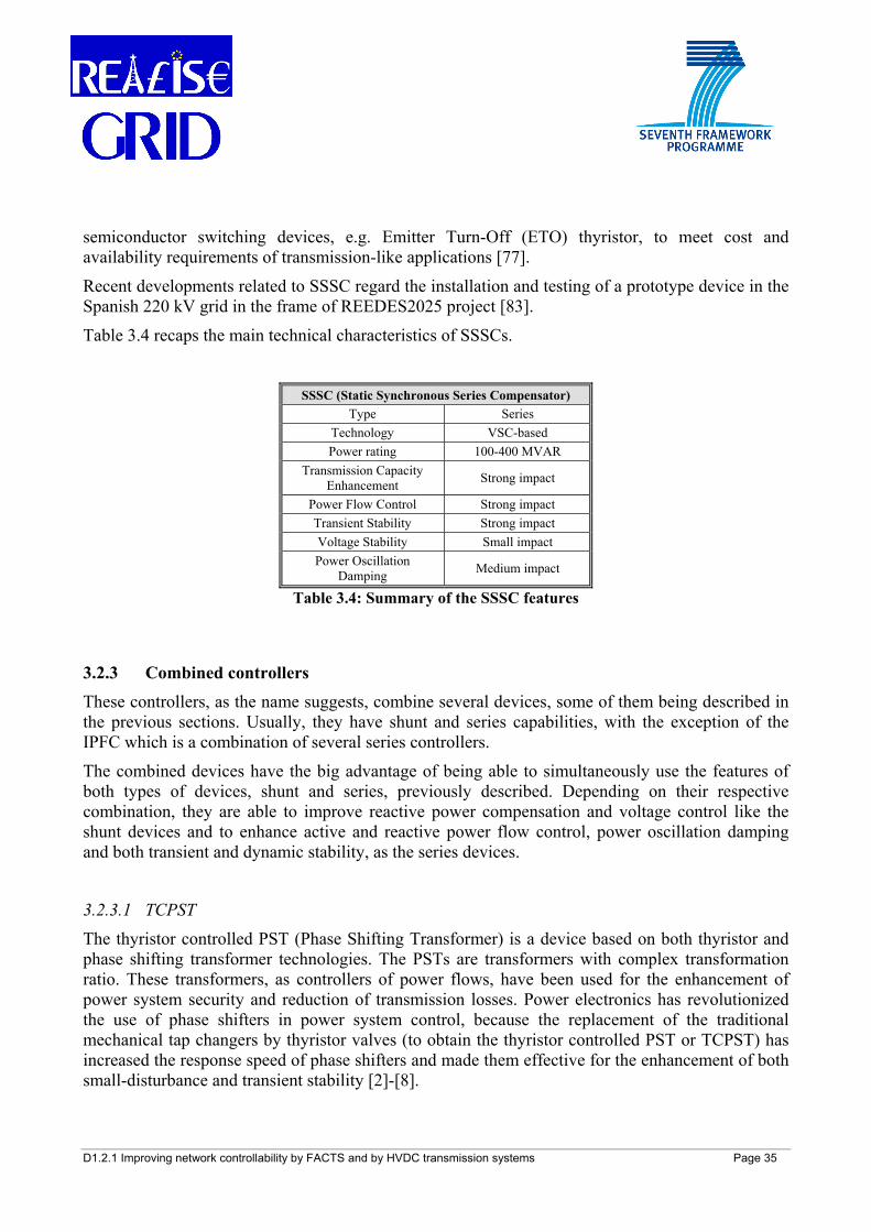
Table 3.4 recaps the main technical characteristics of SSSCs.
SSSC (Static Synchronous Series Compensator) Type Series
Technology VSC-based Power rating 100-400 MVAR
Transmission Capacity Enhancement Strong impact
Power Flow Control Strong impact Transient Stability Strong impact Voltage Stability Small impact Power Oscillation
Damping Medium impact
Table 3.4: Summary of the SSSC features
3.2.3 Combined controllers These controllers, as the name suggests, combine several devices, some of them being described in the previous sections. Usually, they have shunt and series capabilities, with the exception of the IPFC which is a combination of several series controllers.
The combined devices have the big advantage of being able to simultaneously use the features of both types of devices, shunt and series, previously described. Depending on their respective combination, they are able to improve reactive power compensation and voltage control like the shunt devices and to enhance active and reactive power flow control, power oscillation damping and both transient and dynamic stability, as the series devices.
3.2.3.1 TCPST
The thyristor controlled PST (Phase Shifting Transformer) is a device based on both thyristor and phase shifting transformer technologies. The PSTs are transformers with complex transformation ratio. These transformers, as controllers of power flows, have been used for the enhancement of power system security and reduction of transmission losses. Power electronics has revolutionized the use of phase shifters in power system control, because the replacement of the traditional mechanical tap changers by thyristor valves (to obtain the thyristor controlled PST or TCPST) has increased the response speed of phase shifters and made them effective for the enhancement of both small-disturbance and transient stability [2]-[8].
D1.2.1 Improving network controllability by FACTS and by HVDC transmission systems Page 36
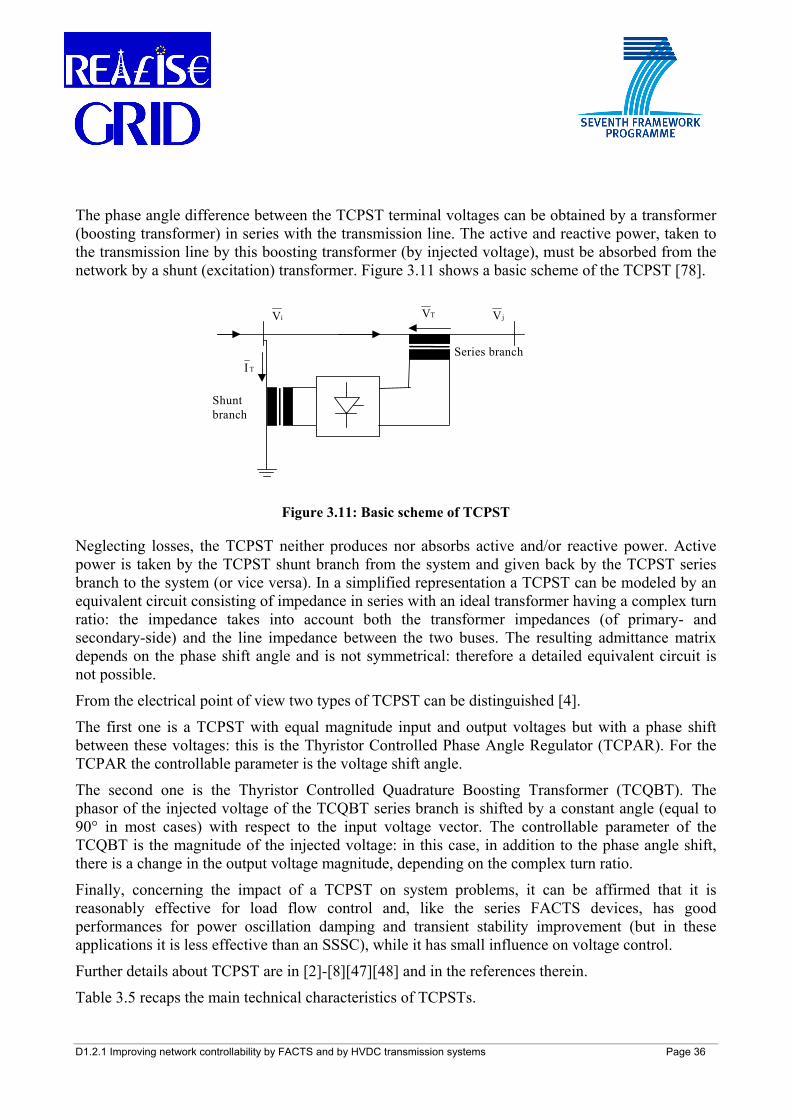
The phase angle difference between the TCPST terminal voltages can be obtained by a transformer (boosting transformer) in series with the transmission line. The active and reactive power, taken to the transmission line by this boosting transformer (by injected voltage), must be absorbed from the network by a shunt (excitation) transformer. Figure 3.11 shows a basic scheme of the TCPST [78].
Series branch
Shunt branch
TV jViV
T I
Figure 3.11: Basic scheme of TCPST
Neglecting losses, the TCPST neither produces nor absorbs active and/or reactive power. Active power is taken by the TCPST shunt branch from the system and given back by the TCPST series branch to the system (or vice versa). In a simplified representation a TCPST can be modeled by an equivalent circuit consisting of impedance in series with an ideal transformer having a complex turn ratio: the impedance takes into account both the transformer impedances (of primary- and secondary-side) and the line impedance between the two buses. The resulting admittance matrix depends on the phase shift angle and is not symmetrical: therefore a detailed equivalent circuit is not possible.
From the electrical point of view two types of TCPST can be distinguished [4].
The first one is a TCPST with equal magnitude input and output voltages but with a phase shift between these voltages: this is the Thyristor Controlled Phase Angle Regulator (TCPAR). For the TCPAR the controllable parameter is the voltage shift angle.
The second one is the Thyristor Controlled Quadrature Boosting Transformer (TCQBT). The phasor of the injected voltage of the TCQBT series branch is shifted by a constant angle (equal to 90° in most cases) with respect to the input voltage vector. The controllable parameter of the TCQBT is the magnitude of the injected voltage: in this case, in addition to the phase angle shift, there is a change in the output voltage magnitude, depending on the complex turn ratio.
Finally, concerning the impact of a TCPST on system problems, it can be affirmed that it is reasonably effective for load flow control and, like the series FACTS devices, has good performances for power oscillation damping and transient stability improvement (but in these applications it is less effective than an SSSC), while it has small influence on voltage control.
Further details about TCPST are in [2]-[8][47][48] and in the references therein.
Table 3.5 recaps the main technical characteristics of TCPSTs.
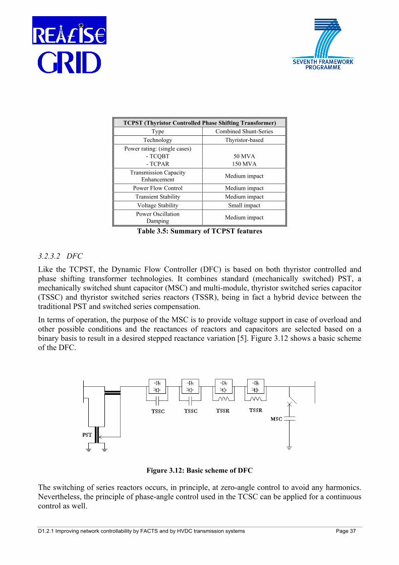
D1.2.1 Improving network controllability by FACTS and by HVDC transmission systems Page 37
TCPST (Thyristor Controlled Phase Shifting Transformer) Type Combined Shunt-Series
Technology Thyristor-based Power rating: (single cases)
- TCQBT - TCPAR
50 MVA 150 MVA
Transmission Capacity Enhancement Medium impact
Power Flow Control Medium impact Transient Stability Medium impact Voltage Stability Small impact Power Oscillation
Damping Medium impact
Table 3.5: Summary of TCPST features
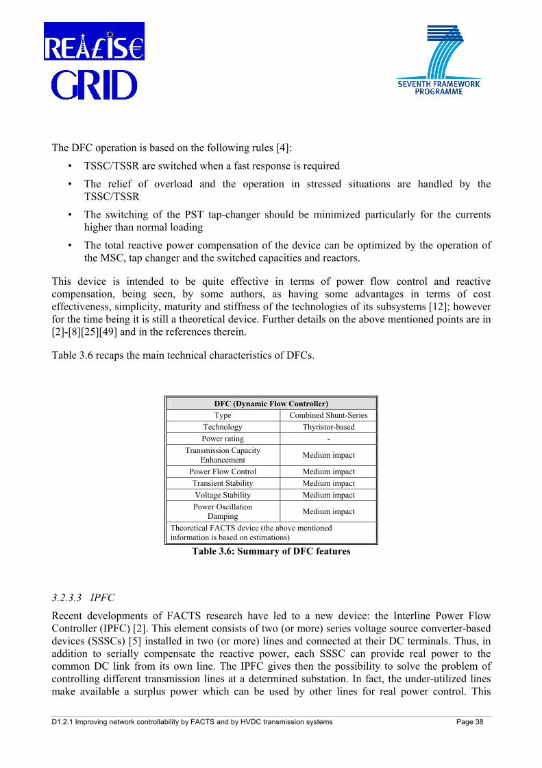
3.2.3.2 DFC
Like the TCPST, the Dynamic Flow Controller (DFC) is based on both thyristor controlled and phase shifting transformer technologies. It combines standard (mechanically switched) PST, a mechanically switched shunt capacitor (MSC) and multi-module, thyristor switched series capacitor (TSSC) and thyristor switched series reactors (TSSR), being in fact a hybrid device between the traditional PST and switched series compensation.
In terms of operation, the purpose of the MSC is to provide voltage support in case of overload and other possible conditions and the reactances of reactors and capacitors are selected based on a binary basis to result in a desired stepped reactance variation [5]. Figure 3.12 shows a basic scheme of the DFC.
Figure 3.12: Basic scheme of DFC
The switching of series reactors occurs, in principle, at zero-angle control to avoid any harmonics. Nevertheless, the principle of phase-angle control used in the TCSC can be applied for a continuous control as well.
D1.2.1 Improving network controllability by FACTS and by HVDC transmission systems Page 38
The DFC operation is based on the following rules [4]:
• TSSC/TSSR are switched when a fast response is required
• The relief of overload and the operation in stressed situations are handled by the TSSC/TSSR
• The switching of the PST tap-changer should be minimized particularly for the currents higher than normal loading
• The total reactive power compensation of the device can be optimized by the operation of the MSC, tap changer and the switched capacities and reactors.
This device is intended to be quite effective in terms of power flow control and reactive compensation, being seen, by some authors, as having some advantages in terms of cost effectiveness, simplicity, maturity and stiffness of the technologies of its subsystems [12]; however for the time being it is still a theoretical device. Further details on the above mentioned points are in [2]-[8][25][49] and in the references therein.
Table 3.6 recaps the main technical characteristics of DFCs.
DFC (Dynamic Flow Controller) Type Combined Shunt-Series
Technology Thyristor-based Power rating -
Transmission Capacity Enhancement Medium impact
Power Flow Control Medium impact Transient Stability Medium impact Voltage Stability Medium impact Power Oscillation
Damping Medium impact
Theoretical FACTS device (the above mentioned information is based on estimations)
Table 3.6: Summary of DFC features
3.2.3.3 IPFC
Recent developments of FACTS research have led to a new device: the Interline Power Flow Controller (IPFC) [2]. This element consists of two (or more) series voltage source converter-based devices (SSSCs) [5] installed in two (or more) lines and connected at their DC terminals. Thus, in addition to serially compensate the reactive power, each SSSC can provide real power to the common DC link from its own line. The IPFC gives then the possibility to solve the problem of controlling different transmission lines at a determined substation. In fact, the under-utilized lines make available a surplus power which can be used by other lines for real power control. This
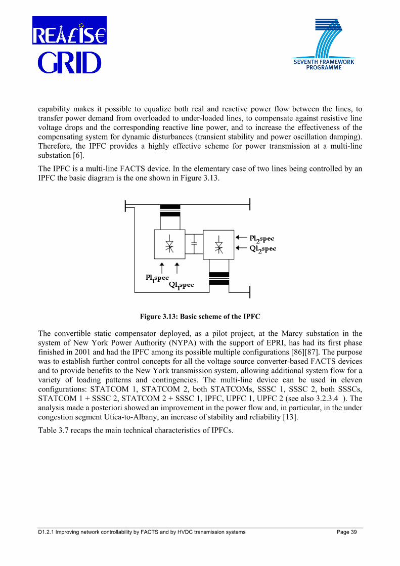
D1.2.1 Improving network controllability by FACTS and by HVDC transmission systems Page 39
capability makes it possible to equalize both real and reactive power flow between the lines, to transfer power demand from overloaded to under-loaded lines, to compensate against resistive line voltage drops and the corresponding reactive line power, and to increase the effectiveness of the compensating system for dynamic disturbances (transient stability and power oscillation damping). Therefore, the IPFC provides a highly effective scheme for power transmission at a multi-line substation [6].
The IPFC is a multi-line FACTS device. In the elementary case of two lines being controlled by an IPFC the basic diagram is the one shown in Figure 3.13.
Figure 3.13: Basic scheme of the IPFC
The convertible static compensator deployed, as a pilot project, at the Marcy substation in the system of New York Power Authority (NYPA) with the support of EPRI, has had its first phase finished in 2001 and had the IPFC among its possible multiple configurations [86][87]. The purpose was to establish further control concepts for all the voltage source converter-based FACTS devices and to provide benefits to the New York transmission system, allowing additional system flow for a variety of loading patterns and contingencies. The multi-line device can be used in eleven configurations: STATCOM 1, STATCOM 2, both STATCOMs, SSSC 1, SSSC 2, both SSSCs, STATCOM 1 + SSSC 2, STATCOM 2 + SSSC 1, IPFC, UPFC 1, UPFC 2 (see also 3.2.3.4 ). The analysis made a posteriori showed an improvement in the power flow and, in particular, in the under congestion segment Utica-to-Albany, an increase of stability and reliability [13].
Table 3.7 recaps the main technical characteristics of IPFCs.
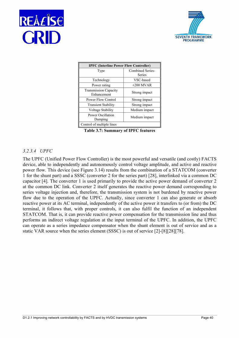
D1.2.1 Improving network controllability by FACTS and by HVDC transmission systems Page 40
IPFC (Interline Power Flow Controller) Type Combined Series-
Series Technology VSC-based Power rating ±200 MVAR
Transmission Capacity Enhancement Strong impact
Power Flow Control Strong impact Transient Stability Strong impact Voltage Stability Medium impact Power Oscillation
Damping Medium impact
Control of multiple lines
Table 3.7: Summary of IPFC features
3.2.3.4 UPFC
The UPFC (Unified Power Flow Controller) is the most powerful and versatile (and costly) FACTS device, able to independently and autonomously control voltage amplitude, and active and reactive power flow. This device (see Figure 3.14) results from the combination of a STATCOM (converter 1 for the shunt part) and a SSSC (converter 2 for the series part) [28], interlinked via a common DC capacitor [4]. The converter 1 is used primarily to provide the active power demand of converter 2 at the common DC link. Converter 2 itself generates the reactive power demand corresponding to series voltage injection and, therefore, the transmission system is not burdened by reactive power flow due to the operation of the UPFC. Actually, since converter 1 can also generate or absorb reactive power at its AC terminal, independently of the active power it transfers to (or from) the DC terminal, it follows that, with proper controls, it can also fulfil the function of an independent STATCOM. That is, it can provide reactive power compensation for the transmission line and thus performs an indirect voltage regulation at the input terminal of the UPFC. In addition, the UPFC can operate as a series impedance compensator when the shunt element is out of service and as a static VAR source when the series element (SSSC) is out of service [2]-[8][28][78].
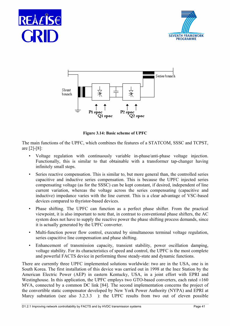
D1.2.1 Improving network controllability by FACTS and by HVDC transmission systems Page 41
Figure 3.14: Basic scheme of UPFC
The main functions of the UPFC, which combines the features of a STATCOM, SSSC and TCPST, are [2]-[8]:
• Voltage regulation with continuously variable in-phase/anti-phase voltage injection. Functionally, this is similar to that obtainable with a transformer tap-changer having infinitely small steps.
• Series reactive compensation. This is similar to, but more general than, the controlled series capacitive and inductive series compensation. This is because the UPFC injected series compensating voltage (as for the SSSC) can be kept constant, if desired, independent of line current variation, whereas the voltage across the series compensating (capacitive and inductive) impedance varies with the line current. This is a clear advantage of VSC-based devices compared to thyristor-based devices.
• Phase shifting. The UPFC can function as a perfect phase shifter. From the practical viewpoint, it is also important to note that, in contrast to conventional phase shifters, the AC system does not have to supply the reactive power the phase shifting process demands, since it is actually generated by the UPFC converter.
• Multi-function power flow control, executed by simultaneous terminal voltage regulation, series capacitive line compensation and phase shifting.
• Enhancement of transmission capacity, transient stability, power oscillation damping, voltage stability. For its characteristics of speed and control, the UPFC is the most complete and powerful FACTS device in performing those steady-state and dynamic functions.
There are currently three UPFC implemented solutions worldwide: two are in the USA, one is in South Korea. The first installation of this device was carried out in 1998 at the Inez Station by the American Electric Power (AEP) in eastern Kentucky, USA, in a joint effort with EPRI and Westinghouse. In this application, the UPFC employs two GTO-based converters, each rated ±160 MVA, connected by a common DC link [84]. The second implementation concerns the project of the convertible static compensator developed by New York Power Authority (NYPA) and EPRI at Marcy substation (see also 3.2.3.3 ): the UPFC results from two out of eleven possible
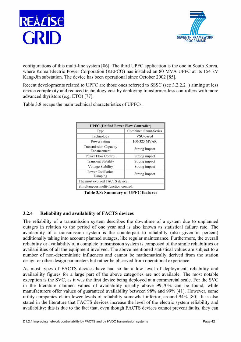
D1.2.1 Improving network controllability by FACTS and by HVDC transmission systems Page 42
configurations of this multi-line system [86]. The third UPFC application is the one in South Korea, where Korea Electric Power Corporation (KEPCO) has installed an 80 MVA UPFC at its 154 kV Kang-Jin substation. The device has been operational since October 2002 [85].
Recent developments related to UPFC are those ones referred to SSSC (see 3.2.2.2 ) aiming at less device complexity and reduced technology cost by deploying transformer-less controllers with more advanced thyristors (e.g. ETO) [77].
Table 3.8 recaps the main technical characteristics of UPFCs.
UPFC (Unified Power Flow Controller) Type Combined Shunt-Series
Technology VSC-based Power rating 100-325 MVAR
Transmission Capacity Enhancement Strong impact
Power Flow Control Strong impact Transient Stability Strong impact Voltage Stability Strong impact Power Oscillation
Damping Strong impact
The most evolved FACTS device. Simultaneous multi-function control.
Table 3.8: Summary of UPFC features
3.2.4 Reliability and availability of FACTS devices The reliability of a transmission system describes the downtime of a system due to unplanned outages in relation to the period of one year and is also known as statistical failure rate. The availability of a transmission system is the counterpart to reliability (also given in percent) additionally taking into account planned outages, like regular maintenance. Furthermore, the overall reliability or availability of a complete transmission system is composed of the single reliabilities or availabilities of all the equipment involved. The above mentioned statistical values are subject to a number of non-deterministic influences and cannot be mathematically derived from the station design or other design parameters but rather be observed from operational experience.
As most types of FACTS devices have had so far a low level of deployment, reliability and availability figures for a large part of the above categories are not available. The most notable exception is the SVC, as it was the first device being deployed at a commercial scale. For the SVC in the literature claimed values of availability usually above 99,70% can be found, while manufacturers offer values of guaranteed availability between 98% and 99% [41]. However, some utility companies claim lower levels of reliability somewhat inferior, around 94% [80]. It is also stated in the literature that FACTS devices increase the level of the electric system reliability and availability: this is due to the fact that, even though FACTS devices cannot prevent faults, they can
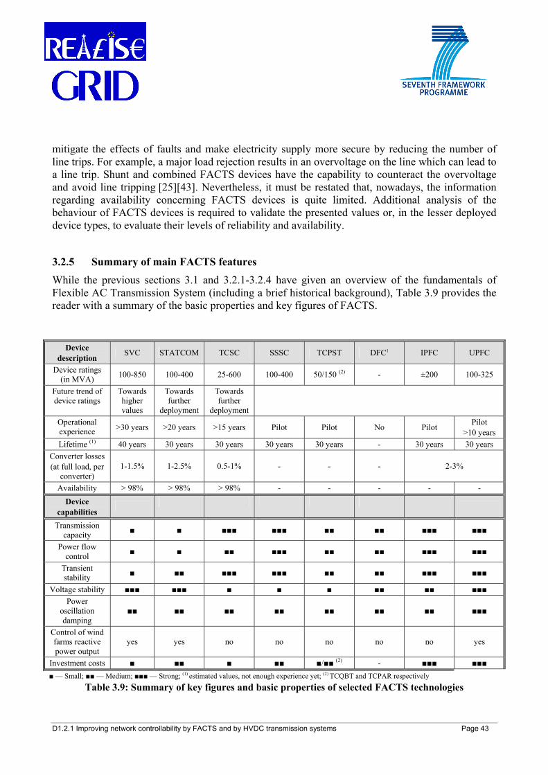
D1.2.1 Improving network controllability by FACTS and by HVDC transmission systems Page 43
mitigate the effects of faults and make electricity supply more secure by reducing the number of line trips. For example, a major load rejection results in an overvoltage on the line which can lead to a line trip. Shunt and combined FACTS devices have the capability to counteract the overvoltage and avoid line tripping [25][43]. Nevertheless, it must be restated that, nowadays, the information regarding availability concerning FACTS devices is quite limited. Additional analysis of the behaviour of FACTS devices is required to validate the presented values or, in the lesser deployed device types, to evaluate their levels of reliability and availability.
3.2.5 Summary of main FACTS features While the previous sections 3.1 and 3.2.1-3.2.4 have given an overview of the fundamentals of Flexible AC Transmission System (including a brief historical background), Table 3.9 provides the reader with a summary of the basic properties and key figures of FACTS.
Device description SVC STATCOM TCSC SSSC TCPST DFC1 IPFC UPFC
Device ratings (in MVA) 100-850 100-400 25-600 100-400 50/150 (2) - ±200 100-325
Future trend of device ratings
Towards higher values
Towards further
deployment
Towards further
deployment
Operational experience >30 years >20 years >15 years Pilot Pilot No Pilot Pilot
>10 years Lifetime (1) 40 years 30 years 30 years 30 years 30 years - 30 years 30 years
Converter losses (at full load, per
converter) 1-1.5% 1-2.5% 0.5-1% - - - 2-3%
Availability > 98% > 98% > 98% - - - - - Device
capabilities
Transmission capacity ■ ■ ■■■ ■■■ ■■ ■■ ■■■ ■■■
Power flow control ■ ■ ■■ ■■■ ■■ ■■ ■■■ ■■■
Transient stability ■ ■■ ■■■ ■■■ ■■ ■■ ■■■ ■■■
Voltage stability ■■■ ■■■ ■ ■ ■ ■■ ■■ ■■■ Power
oscillation damping
■■ ■■ ■■ ■■ ■■ ■■ ■■ ■■■
Control of wind farms reactive power output
yes yes no no no no no yes
Investment costs ■ ■■ ■ ■■ ■/■■ (2) - ■■■ ■■■ ■ — Small; ■■ — Medium; ■■■ — Strong; (1) estimated values, not enough experience yet; (2) TCQBT and TCPAR respectively
Table 3.9: Summary of key figures and basic properties of selected FACTS technologies
D1.2.1 Improving network controllability by FACTS and by HVDC transmission systems Page 44
4 TECHNOLOGICAL OVERVIEW OF HIGH VOLTAGE DIRECT CURRENT (HVDC) TRANSMISSION
4.1 Brief historical background As of 2009, with more than 50 years of experience in operation of Current Source Converter (CSC)-HVDC (High Voltage Direct Current)4, the transmission of bulk power by Direct Current (DC) is considered to be a mature and well-understood technology. Early HVDC installations went into service in the 1950s and 1960s in different systems all over the world, some of them still being in operation as, for instance, the Wolgograd-Donbass interconnection or the SACOI link between the island of Sardinia, the island of Corsica and the Italian power grid.
Since the progress of HVDC is closely linked to the further development of the power converter technology, the applicability of HVDC in power transmission evolved in stages. After the availability of mercury arc rectifiers, the first commercial HVDC line went into service in 1954 connecting the island of Gotland to the Swedish mainland [14]. However, due to the high losses of mercury arc rectifiers and their complex handling, the main use of HVDC remained limited to special applications such as long-distance undersea cable transmission. Things changed when thyristors entered the market in the 1970s and solid-state rectifiers became available. Offering easier maintenance and operation, less losses, and a higher current rating than mercury arc rectifiers, thyristors opened up new fields of application for HVDC as a bulk-power transmission technology. Since then, CSC-HVDC transmission is the state-of-the-art technology for long-distance cable transmission, for bulk power transmission over long distances and for the back-to-back connection of asynchronously operated power grids [15]. Today, there are more than hundred HVDC installations worldwide, with over 60 GW installed. Further breakthroughs in the field of CSC-HVDC are expected in China (with the newest, world-record 800 kV, 6400 MW installations) and in Brazil (with the world’s longest transmission link, 2500 km long HVDC installation).
Moreover, in the 1990s, the marketability of Insulated Gate Bipolar Transistors (IGBT) and Gate Turn-Off Thyristors (GTO) added new features to the HVDC transmission technology that made it overcome the essential disadvantages of thyristor-controlled, line-commutated HVDC of the 1970s: thanks to the use of IGBTs and GTOs that can not only be switched on5 but also switched off6, self-commutating Voltage Source Converter (VSC)-HVDC became possible. Similar developments were made possible also for FACTS evolution, as seen in Chapter 3.
Nowadays, also VSC-HVDC is more and more frequently considered, even for point-to-point interconnections within a meshed power grid. In particular, the number of VSC-based HVDC projects worldwide tends to increase more and more quickly. According to [10] and [11], the total rating of VSC-based HVDC projects worldwide will exceed 2400 MW by 2010, currently the largest one being 350 MW with a rated voltage of ±150 kV DC. Since 1998 more than 1500 km of
4 Depending on the source of information, CSC-HVDC is occasionally also referred to as line-commutated converter
(LCC) HVDC. In this work, CSC-HVDC is preferred. 5 In this context, this means switching the valve from the blocking state to the on-state. 6 In this context, this means forcing the valve from the on-state to the blocking state.
D1.2.1 Improving network controllability by FACTS and by HVDC transmission systems Page 45
VSC-based HVDC cables have been laid [16]. The installation of a ±150 kV VSC-based HVDC system, consisting of 2×129 km of submarine DC cable, 2×75 km of underground DC cable, and 1 km of submarine three-phase AC cable is expected to be completed by ABB in 2010, connecting an offshore wind farm in Germany to the power grid [10][16]. Further VSC-HVDC undersea projects ongoing or planned in Europe concern Estlink 1 and Estlink 2 (between Finland and Estonia), the East-West interconnector (between Ireland and Wales) and the NordBalt (between Lithuania and Sweden). Also, VSC-HVDC underground installations are planned or under study for the South-West link (between Norway and Sweden) and for the new France-Spain corridor [90].
4.2 Description of technological features Modern HVDC transmission systems do not only allow for electrical power transmission from one area to another but also offer several technical advantages over conventional HVAC transmission. These essential advantages are briefly described as follows [16]:
1. No limitation in transmission line length:
HVDC transmission systems offer the special capability needed to carry out long submarine or underground cable transmission lines with a low level of losses - differently from AC cable transmission - without the need of reactive compensation. As there is no charging current in the DC cable, the transmission distance is almost unlimited and losses are lower for long-distance transmission compared to those ones of AC cables in equal conditions.
2. Transmission capacity increase:
For a given conductor cross section, HVDC transmission can transfer more current through a conductor compared to conventional HVAC transmission. Accordingly, the conversion of transmission lines, formerly operated with HVAC, into HVDC operated ones increases the transmission capacity of the considered line. Such an increase in transmission capacity could be very worthwhile in liberalized power systems, e.g. for cross-border trade [18].
3. Ability of quick and bi-directional control of power flow:
Active power can be transmitted in both directions and quickly reversed if needed. Also, the amount of transmitted active power can be set to a fixed value that is maintained during all operating conditions, especially during the occurrence of faults in neighbouring network sections. This avoids the overloading and the consecutive loss of the transmission line. These features of HVDC can improve the stability of the surrounding AC power system or even of the total network.
4. No increase of short-circuit power at the connection points:
HVDC lines can be integrated into a power grid without the need to upgrade downstream equipment, e.g. circuit breakers, transformers etc. In case of short-circuit at one of the terminals of the HVDC transmission line, the converters can be switched off within milliseconds preventing them from contributing to the short-circuit current.
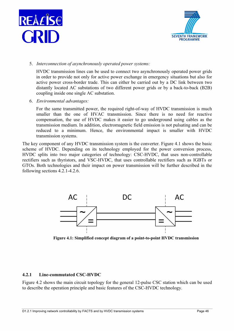
D1.2.1 Improving network controllability by FACTS and by HVDC transmission systems Page 46
5. Interconnection of asynchronously operated power systems:
HVDC transmission lines can be used to connect two asynchronously operated power grids in order to provide not only for active power exchange in emergency situations but also for active power cross-border trade. This can either be carried out by a DC link between two distantly located AC substations of two different power grids or by a back-to-back (B2B) coupling inside one single AC substation.
6. Environmental advantages:
For the same transmitted power, the required right-of-way of HVDC transmission is much smaller than the one of HVAC transmission. Since there is no need for reactive compensation, the use of HVDC makes it easier to go underground using cables as the transmission medium. In addition, electromagnetic field emission is not pulsating and can be reduced to a minimum. Hence, the environmental impact is smaller with HVDC transmission systems.
The key component of any HVDC transmission system is the converter. Figure 4.1 shows the basic scheme of HVDC. Depending on its technology employed for the power conversion process, HVDC splits into two major categories of technology: CSC-HVDC, that uses non-controllable rectifiers such as thyristors, and VSC-HVDC, that uses controllable rectifiers such as IGBTs or GTOs. Both technologies and their impact on power transmission will be further described in the following sections 4.2.1-4.2.6.
4.2.1 Line-commutated CSC-HVDC Figure 4.2 shows the main circuit topology for the general 12-pulse CSC station which can be used to describe the operation principle and basic features of the CSC-HVDC technology.
~=
~=
AC ACDC
Figure 4.1: Simplified concept diagram of a point-to-point HVDC transmission
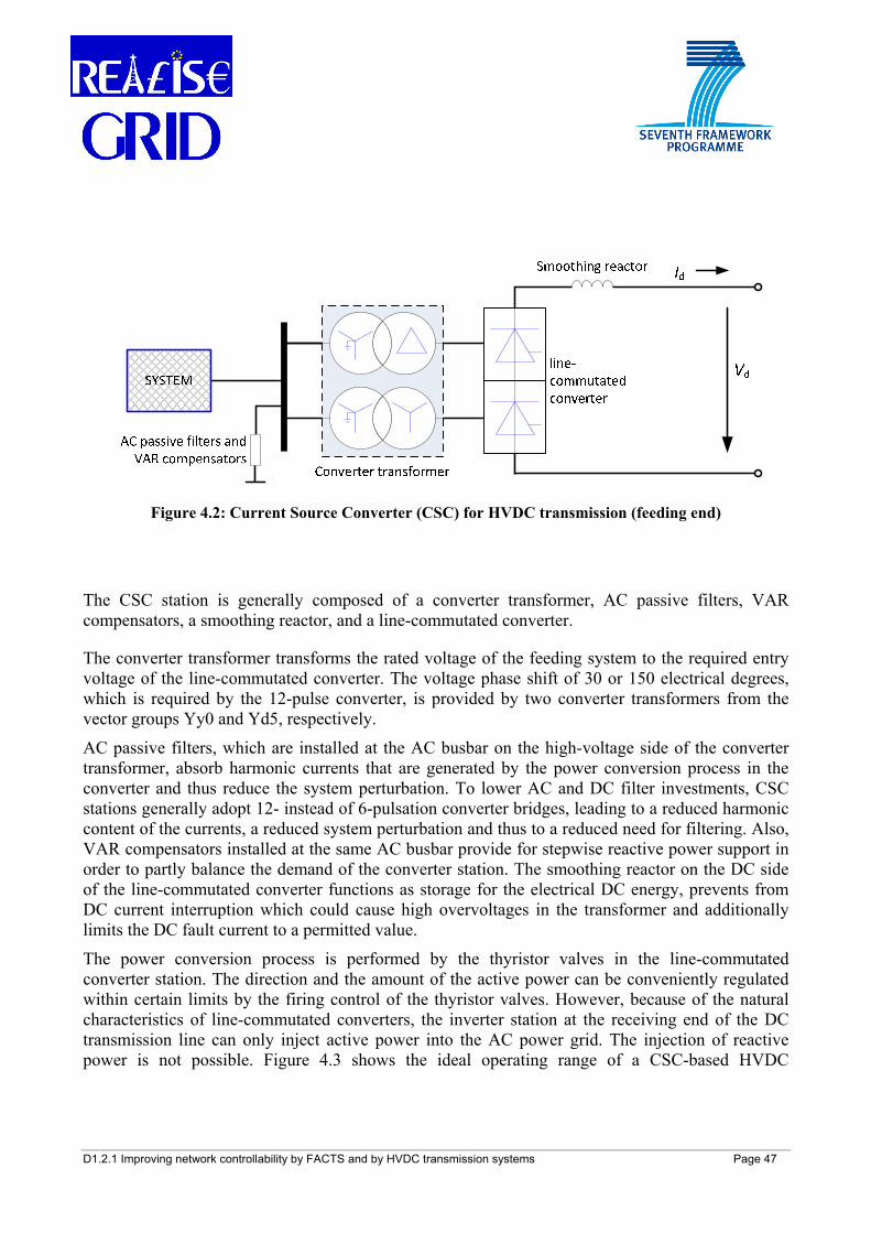
D1.2.1 Improving network controllability by FACTS and by HVDC transmission systems Page 47
The CSC station is generally composed of a converter transformer, AC passive filters, VAR compensators, a smoothing reactor, and a line-commutated converter.
The converter transformer transforms the rated voltage of the feeding system to the required entry voltage of the line-commutated converter. The voltage phase shift of 30 or 150 electrical degrees, which is required by the 12-pulse converter, is provided by two converter transformers from the vector groups Yy0 and Yd5, respectively.
AC passive filters, which are installed at the AC busbar on the high-voltage side of the converter transformer, absorb harmonic currents that are generated by the power conversion process in the converter and thus reduce the system perturbation. To lower AC and DC filter investments, CSC stations generally adopt 12- instead of 6-pulsation converter bridges, leading to a reduced harmonic content of the currents, a reduced system perturbation and thus to a reduced need for filtering. Also, VAR compensators installed at the same AC busbar provide for stepwise reactive power support in order to partly balance the demand of the converter station. The smoothing reactor on the DC side of the line-commutated converter functions as storage for the electrical DC energy, prevents from DC current interruption which could cause high overvoltages in the transformer and additionally limits the DC fault current to a permitted value.
The power conversion process is performed by the thyristor valves in the line-commutated converter station. The direction and the amount of the active power can be conveniently regulated within certain limits by the firing control of the thyristor valves. However, because of the natural characteristics of line-commutated converters, the inverter station at the receiving end of the DC transmission line can only inject active power into the AC power grid. The injection of reactive power is not possible. Figure 4.3 shows the ideal operating range of a CSC-based HVDC
Figure 4.2: Current Source Converter (CSC) for HVDC transmission (feeding end)
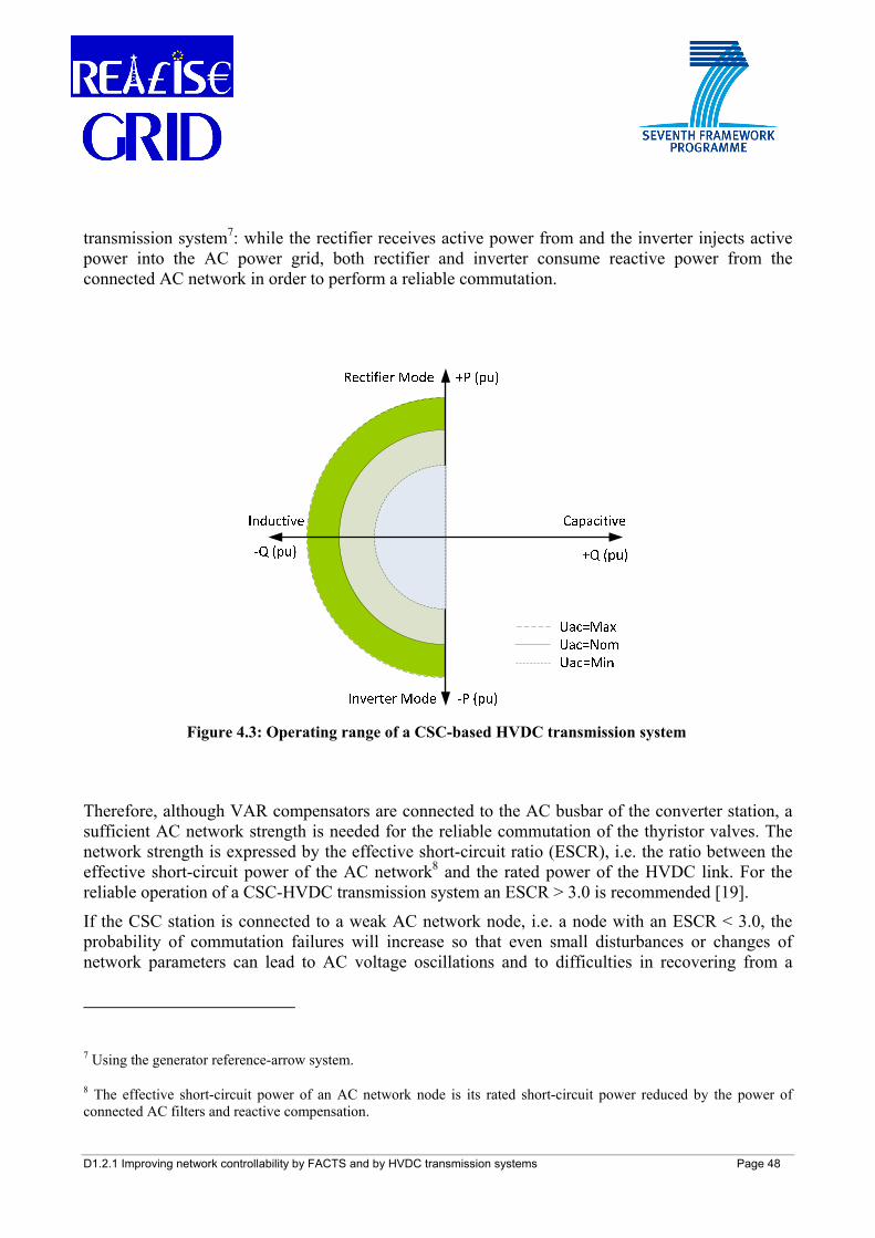
D1.2.1 Improving network controllability by FACTS and by HVDC transmission systems Page 48
transmission system7: while the rectifier receives active power from and the inverter injects active power into the AC power grid, both rectifier and inverter consume reactive power from the connected AC network in order to perform a reliable commutation.
Therefore, although VAR compensators are connected to the AC busbar of the converter station, a sufficient AC network strength is needed for the reliable commutation of the thyristor valves. The network strength is expressed by the effective short-circuit ratio (ESCR), i.e. the ratio between the effective short-circuit power of the AC network8 and the rated power of the HVDC link. For the reliable operation of a CSC-HVDC transmission system an ESCR > 3.0 is recommended [19].
If the CSC station is connected to a weak AC network node, i.e. a node with an ESCR < 3.0, the probability of commutation failures will increase so that even small disturbances or changes of network parameters can lead to AC voltage oscillations and to difficulties in recovering from a
7 Using the generator reference-arrow system.
8 The effective short-circuit power of an AC network node is its rated short-circuit power reduced by the power of connected AC filters and reactive compensation.
Figure 4.3: Operating range of a CSC-based HVDC transmission system
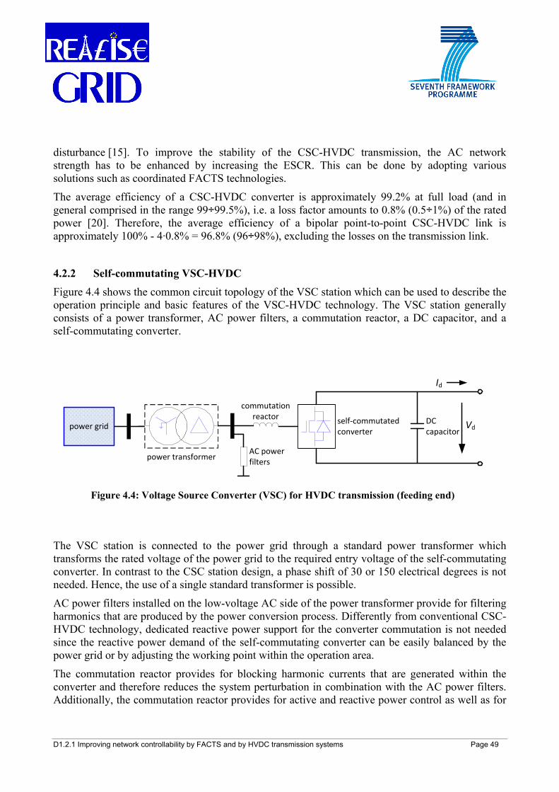
D1.2.1 Improving network controllability by FACTS and by HVDC transmission systems Page 49
disturbance [15]. To improve the stability of the CSC-HVDC transmission, the AC network strength has to be enhanced by increasing the ESCR. This can be done by adopting various solutions such as coordinated FACTS technologies.
The average efficiency of a CSC-HVDC converter is approximately 99.2% at full load (and in general comprised in the range 99÷99.5%), i.e. a loss factor amounts to 0.8% (0.5÷1%) of the rated power [20]. Therefore, the average efficiency of a bipolar point-to-point CSC-HVDC link is approximately 100% - 4·0.8% = 96.8% (96÷98%), excluding the losses on the transmission link.
4.2.2 Self-commutating VSC-HVDC Figure 4.4 shows the common circuit topology of the VSC station which can be used to describe the operation principle and basic features of the VSC-HVDC technology. The VSC station generally consists of a power transformer, AC power filters, a commutation reactor, a DC capacitor, and a self-commutating converter.
The VSC station is connected to the power grid through a standard power transformer which transforms the rated voltage of the power grid to the required entry voltage of the self-commutating converter. In contrast to the CSC station design, a phase shift of 30 or 150 electrical degrees is not needed. Hence, the use of a single standard transformer is possible.
AC power filters installed on the low-voltage AC side of the power transformer provide for filtering harmonics that are produced by the power conversion process. Differently from conventional CSC-HVDC technology, dedicated reactive power support for the converter commutation is not needed since the reactive power demand of the self-commutating converter can be easily balanced by the power grid or by adjusting the working point within the operation area.
The commutation reactor provides for blocking harmonic currents that are generated within the converter and therefore reduces the system perturbation in combination with the AC power filters. Additionally, the commutation reactor provides for active and reactive power control as well as for
AC power filters
power grid
commutation reactor DC
capacitor
Id
Vd
power transformer
self‐commutated converter
Figure 4.4: Voltage Source Converter (VSC) for HVDC transmission (feeding end)
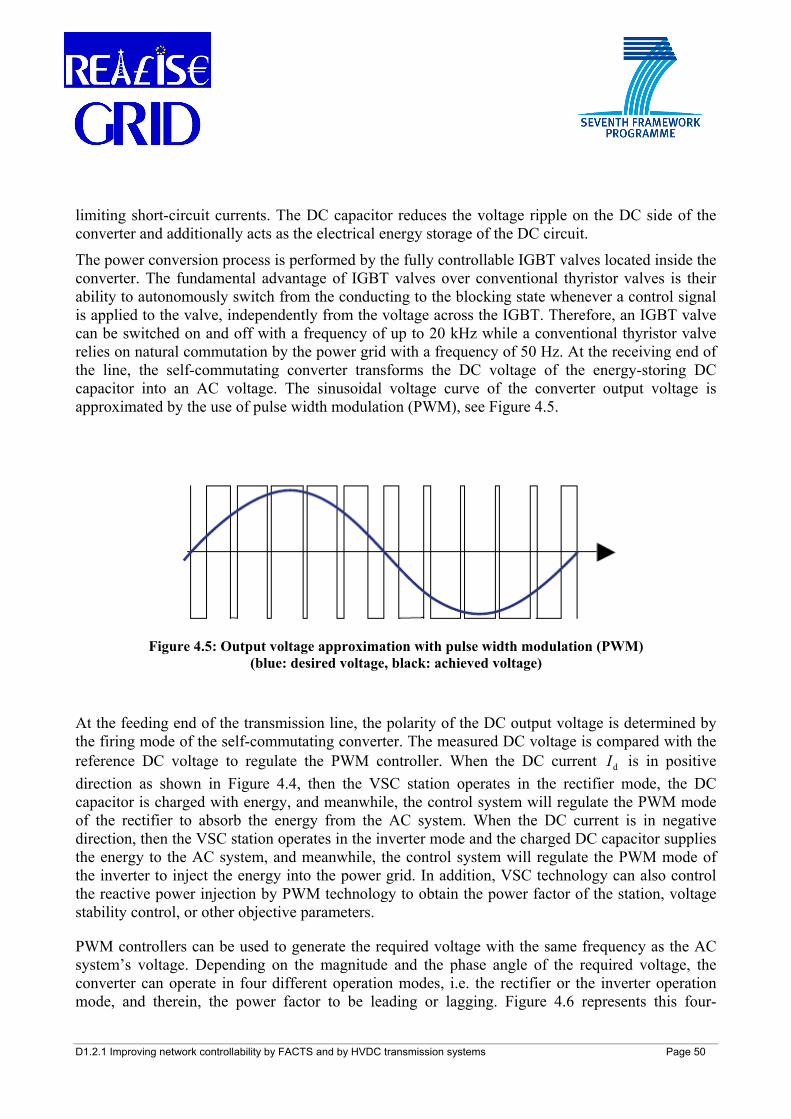
D1.2.1 Improving network controllability by FACTS and by HVDC transmission systems Page 50
limiting short-circuit currents. The DC capacitor reduces the voltage ripple on the DC side of the converter and additionally acts as the electrical energy storage of the DC circuit.
The power conversion process is performed by the fully controllable IGBT valves located inside the converter. The fundamental advantage of IGBT valves over conventional thyristor valves is their ability to autonomously switch from the conducting to the blocking state whenever a control signal is applied to the valve, independently from the voltage across the IGBT. Therefore, an IGBT valve can be switched on and off with a frequency of up to 20 kHz while a conventional thyristor valve relies on natural commutation by the power grid with a frequency of 50 Hz. At the receiving end of the line, the self-commutating converter transforms the DC voltage of the energy-storing DC capacitor into an AC voltage. The sinusoidal voltage curve of the converter output voltage is approximated by the use of pulse width modulation (PWM), see Figure 4.5.
At the feeding end of the transmission line, the polarity of the DC output voltage is determined by the firing mode of the self-commutating converter. The measured DC voltage is compared with the reference DC voltage to regulate the PWM controller. When the DC current dI is in positive direction as shown in Figure 4.4, then the VSC station operates in the rectifier mode, the DC capacitor is charged with energy, and meanwhile, the control system will regulate the PWM mode of the rectifier to absorb the energy from the AC system. When the DC current is in negative direction, then the VSC station operates in the inverter mode and the charged DC capacitor supplies the energy to the AC system, and meanwhile, the control system will regulate the PWM mode of the inverter to inject the energy into the power grid. In addition, VSC technology can also control the reactive power injection by PWM technology to obtain the power factor of the station, voltage stability control, or other objective parameters.
PWM controllers can be used to generate the required voltage with the same frequency as the AC system’s voltage. Depending on the magnitude and the phase angle of the required voltage, the converter can operate in four different operation modes, i.e. the rectifier or the inverter operation mode, and therein, the power factor to be leading or lagging. Figure 4.6 represents this four-
Figure 4.5: Output voltage approximation with pulse width modulation (PWM) (blue: desired voltage, black: achieved voltage)
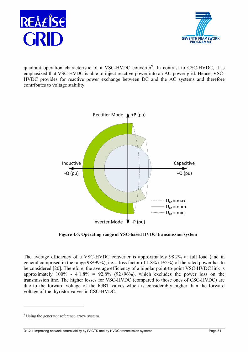
D1.2.1 Improving network controllability by FACTS and by HVDC transmission systems Page 51
quadrant operation characteristic of a VSC-HVDC converter9. In contrast to CSC-HVDC, it is emphasized that VSC-HVDC is able to inject reactive power into an AC power grid. Hence, VSC-HVDC provides for reactive power exchange between DC and the AC systems and therefore contributes to voltage stability.
The average efficiency of a VSC-HVDC converter is approximately 98.2% at full load (and in general comprised in the range 98÷99%), i.e. a loss factor of 1.8% (1÷2%) of the rated power has to be considered [20]. Therefore, the average efficiency of a bipolar point-to-point VSC-HVDC link is approximately 100% - 4·1.8% = 92.8% (92÷96%), which excludes the power loss on the transmission line. The higher losses for VSC-HVDC (compared to those ones of CSC-HVDC) are due to the forward voltage of the IGBT valves which is considerably higher than the forward voltage of the thyristor valves in CSC-HVDC.
9 Using the generator reference arrow system.
+Q (pu)
+P (pu)
‐P (pu)
‐Q (pu)
Inductive Capacitive
Rectifier Mode
Inverter Mode
Uac = max.Uac = nom.Uac = min.
Figure 4.6: Operating range of VSC-based HVDC transmission system
D1.2.1 Improving network controllability by FACTS and by HVDC transmission systems Page 52
VSC-based HVDC with cable transmission has a lot of interesting properties for the application in interconnections of electrical power networks. It can realize the following goals: increase of transmission capacity, full control of power flow in both directions, prevention of fault propagation, improvement of low-frequency stability and of voltage stability as well as reduction of the active power losses in the networks. It can be expected that, with the development of advanced control and design technologies, new power materials and power electronics, VSC-based HVDC transmission will have a bright development and application prospects in future power networks.
4.2.3 Reliability and availability of HVDC transmission links Recalling what was stated in section 3.2.4, the reliability of a transmission system describes the downtime of a system due to unplanned outages in relation to the period of one year and is also known as statistical failure rate. The availability of a transmission system is the counterpart to reliability (also given in percent) additionally taking into account planned outages, like regular maintenance. Furthermore, the overall reliability or availability of a complete transmission system is composed of the single reliabilities or availabilities of all the equipment involved. The above mentioned statistical values are subject to a number of non-deterministic influences and cannot be mathematically derived from the station design or other design parameters but rather be observed from operational experience.
While generally an overall availability in the region of about 98% for both CSC- and VSC-HVDC transmission systems is claimed by the manufacturers [21] and can therefore be contracted, higher availabilities are observed from installations currently being under operation with undersea or underground cables. From the comprehensive records of CSC-HVDC operation, an availability of 98-99% can be deduced [20]-[23]. It has also to be stated that there is only little experience in the operation of self-commutating VSC-HVDC transmission systems yet so that reported availabilities have to be handled with care. Manufacturers claim an availability of also at least 98% (if not about 99%) [24]. However, it shall be stressed that at time of writing the availability records for VSC- HVDC were too small to deduce absolutely reliable data from such a little sample. Further observational studies in the field of VSC-HVDC are necessary to confirm the presently assumed values.
4.2.4 Summary of main HVDC features
While the previous sections 4.1 and 4.2.1-4.2.3 have given an overview of the fundamentals of High Voltage Direct Current transmission (including a brief historical background), Table 4.1 provides the reader with a summary of the basic properties and key figures of HVDC transmission.
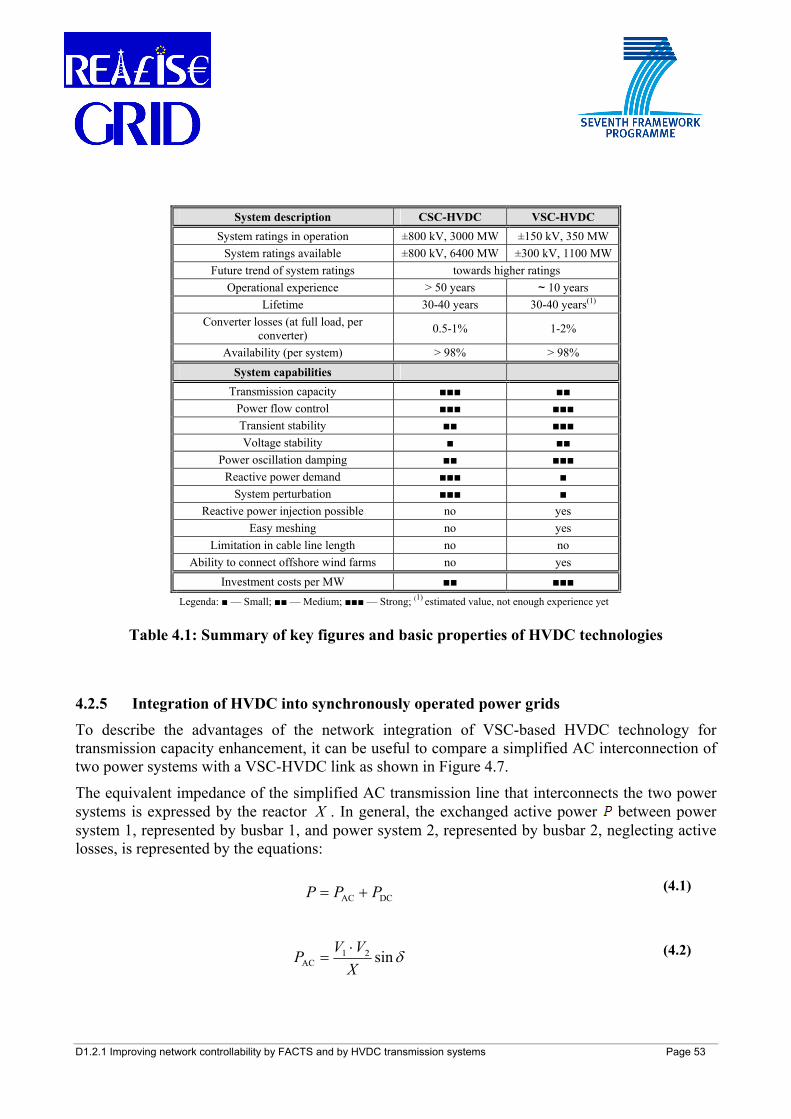
D1.2.1 Improving network controllability by FACTS and by HVDC transmission systems Page 53
System description CSC-HVDC VSC-HVDC System ratings in operation ±800 kV, 3000 MW ±150 kV, 350 MW
System ratings available ±800 kV, 6400 MW ±300 kV, 1100 MW Future trend of system ratings towards higher ratings
Operational experience > 50 years ~ 10 years Lifetime 30-40 years 30-40 years(1)
Converter losses (at full load, per converter) 0.5-1% 1-2%
Availability (per system) > 98% > 98% System capabilities
Transmission capacity ■■■ ■■ Power flow control ■■■ ■■■ Transient stability ■■ ■■■ Voltage stability ■ ■■
Power oscillation damping ■■ ■■■ Reactive power demand ■■■ ■
System perturbation ■■■ ■ Reactive power injection possible no yes
Easy meshing no yes Limitation in cable line length no no
Ability to connect offshore wind farms no yes Investment costs per MW ■■ ■■■
Legenda: ■ — Small; ■■ — Medium; ■■■ — Strong; (1) estimated value, not enough experience yet
Table 4.1: Summary of key figures and basic properties of HVDC technologies
4.2.5 Integration of HVDC into synchronously operated power grids To describe the advantages of the network integration of VSC-based HVDC technology for transmission capacity enhancement, it can be useful to compare a simplified AC interconnection of two power systems with a VSC-HVDC link as shown in Figure 4.7.
The equivalent impedance of the simplified AC transmission line that interconnects the two power systems is expressed by the reactor X . In general, the exchanged active power between power system 1, represented by busbar 1, and power system 2, represented by busbar 2, neglecting active losses, is represented by the equations:
DCAC PPP += (4.1)
δsin21AC X
VVP ⋅= (4.2)
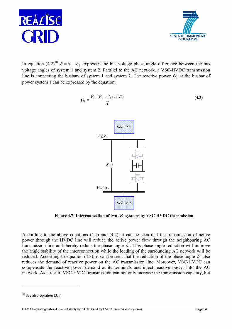
D1.2.1 Improving network controllability by FACTS and by HVDC transmission systems Page 54
In equation (4.2)10 21 δδδ −= expresses the bus voltage phase angle difference between the bus voltage angles of system 1 and system 2. Parallel to the AC network, a VSC-HVDC transmission line is connecting the busbars of system 1 and system 2. The reactive power 1Q at the busbar of power system 1 can be expressed by the equation:
According to the above equations (4.1) and (4.2), it can be seen that the transmission of active power through the HVDC line will reduce the active power flow through the neighbouring AC transmission line and thereby reduce the phase angle δ . This phase angle reduction will improve the angle stability of the interconnection while the loading of the surrounding AC network will be reduced. According to equation (4.3), it can be seen that the reduction of the phase angle δ also reduces the demand of reactive power on the AC transmission line. Moreover, VSC-HVDC can compensate the reactive power demand at its terminals and inject reactive power into the AC network. As a result, VSC-HVDC transmission can not only increase the transmission capacity, but
10 See also equation (3.1)
XVVVQ )cos( 211
1δ−⋅
= (4.3)
11 δ∠V
X
22 δ∠V
Figure 4.7: Interconnection of two AC systems by VSC-HVDC transmission
D1.2.1 Improving network controllability by FACTS and by HVDC transmission systems Page 55
also dynamically compensate the reactive power demand at the AC buses, and improve the voltage stability of the AC bus and of the networks.
4.2.6 Multi-terminal HVDC (MTDC) Although there are currently just few multi-terminal HVDC (MTDC) installations in operation worldwide (in Europe the only one is the Sardinia-Corsica-Italian peninsula), the demand for a MTDC system frequently arises among TSOs: this is mainly driven by the operational advantages in terms of bulk power transmission which they have gained from conventional point-to-point HVDC installations and which they expect to come along with the implementation of MTDC. In addition, the recent push for increasing the share of renewable energy resources in the power generation mix on the one hand leads to an increased number of offshore wind parks in operation, under construction or being planned. The consequence is an increased amount of power generation far away from the load centers. A multi-terminal HVDC system could be a solution for picking up offshore generated power, for transmitting it to the mainland and for feeding it into the power grid. On the other hand, the increasing power trade within the ENTSO-E power grid requires more and more transmission capacity, in many cases over long distances, while the limit of ampacity11 of many lines on the most utilized trade axes has already been reached. In order to support the power trade and reinforce the main interconnection axes the idea of a European supergrid has been conceived [90]: this long-term vision could be based on a MTDC backbone (running from Northern to Southern Europe) whose tap lines pick up the power from generation centers and feed it into the load centers, respectively .
Figure 4.8 shows the three basic configurations of MTDC systems with parallel, series, and hybrid structure, respectively. The presented schemes can be composed of both either CSC or VSC converters. However, VSC-HVDC is generally accepted to be more suitable for multi-terminal applications than CSC-HVDC for the following reasons [21]:
1. Within a CSC-HVDC transmission scheme, the direction of power flow is changed by reversing the DC voltage polarity while maintaining DC current flow direction. Therefore, when using CSC converters in a MTDC network, the insulation system must be designed for quick voltage reversal and dedicated DC switchgear must be installed. VSC converters do not need such a special design since in VSC-MTDC voltage polarity is never reversed.
2. In contrast to CSC converters, VSC converters can avoid commutation failures by adjusting their control scheme. In the case of CSC MTDC, a commutation failure results in a DC voltage collapse which in turn results in a blackout of the entire DC system until all connected CSC terminals have restarted.
3. In a MTDC network, the performance of the overall HVDC system is limited by the converter with the lowest performance, i.e. the converter that is connected to the network
11 The ampacity of a conductor is that maximum constant current which will meet the design, security and safety criteria of a particular line on which the conductor is used [87].

D1.2.1 Improving network controllability by FACTS and by HVDC transmission systems Page 56
node with the lowest ESCR. Therefore, the use of VSC converters is favoured since they are less influenced by the ESCR than CSC converters.
4. In a CSC-MTDC scheme, communication between the converters is necessary in order to balance the power flow and to coordinate the change of voltage polarity in case of change of power flow direction at one CSC terminal. In a VSC-MTDC scheme, no communication between the terminals is needed since balance of power flow can be achieved by monitoring the system voltage.
For the above mentioned reasons, the focus in the following will be mostly concentrated to MTDC systems composed of VSC converters.
(a) (b)
(c)
Figure 4.8: Multi-terminal VSC-HVDC transmission (a) parallel structure, (b) series structure, (c) hybrid structure
D1.2.1 Improving network controllability by FACTS and by HVDC transmission systems Page 57
The wiring schemes presented in Figure 4.8 come along with technical advantages and disadvantages, which can be summarized as follows:
1. Controllability of load distribution:
As for the parallel structure (Figure 4.8(a)), the load distribution for each VSC station can be conveniently controlled by controlling the injected line current, which means a wider range of load flow control. However, as for the series structure (Figure 4.8(b)), the change of the load distribution has to be implemented by the voltage control of each VSC station. In this case, the controllability of the parallel structure is better than that one of the series structure.
2. Reversal control for power flow:
As for the MTDC system with series structure, bidirectional power flow control can easily be realized with both CSC- and VSC-HVDC, even on the condition that the strength of the connected AC system is weak. In the parallel structure using CSC-HVDC, reversal of power flow needs special control schemes and communications while in the parallel structure using VSC-HVDC reversal of power flow can be easily achieved by current control.
3. Controllability in fault mode:
During fault occurrence in a VSC station of a MTDC system, as for the parallel structure, the VSC station with fault condition can be switched off by the control system; at the same time, the other VSC stations in the MTDC system can maintain in the operating state by taking advantage of the overload capability of the VSC station and of the transmission line. In contrast, as for the series structure, a fault in a VSC station leads to a blackout of the entire MTDC system.
4. Insulation coordination of MTDC systems:
As for the parallel structure, because of the same AC and DC voltage level for each parallel VSC station, coordination of insulation can easily be carried out. However, as for the series structure, the varying DC voltage levels for each series VSC station make the insulation coordination more complex and difficult.
5. Flexibility for the expansion of MTDC systems:
Generally, MTDC systems with parallel structure can be conveniently expanded by expanding the DC backbone and adding VSC stations, but in case of the series structure, such an expansion is complex since the DC ring must be split up and the entire MTDC grid needs to be taken out of service during the expansion time.
6. Hybrid structure:
The hybrid structure combines the technical characteristics of the parallel and the series structure. Such a network can be beneficial in interconnected power systems if its advantages and disadvantages are properly considered. However, control of a hybrid system is complex and a clear need for such an HVDC network structure is not considered to arise
D1.2.1 Improving network controllability by FACTS and by HVDC transmission systems Page 58
within the near future since in many cases the parallel HVDC structure will be able to fulfil future requirements.
Taking into account the above mentioned advantages and disadvantages, it can be foreseen that the parallel structure composed of VSC-HVDC converters (see Figure 4.8(a)) could be a solution to cope with the future requirements in bulk-power transmission. However, the reliable and stable operation of MTDC systems is of utmost importance for TSOs. Especially in MTDC networks, there is an urgent need for selective fault clearance, i.e. the isolation of a faulty section from the rest of the network. In case a faulty section cannot be immediately separated from the network, it will impact the entire MTDC system and force the connected AC grid to disconnect. This leads to a change of the overall network topology and may result in a severe congestion of the remaining power grid which in turn may lead to a blackout of a large part of the network. Unselective fault clearance, i.e. the shutdown of the entire MTDC in which the faulty section is located, is not an option: although the faulty section may be disconnected during the downtime of the entire MTDC system and the rest of system may then be re-energized, the required time for this procedure is accepted to be too long in order to guarantee the safe and reliable operation of the overall network. Therefore, differently from the conventional two-terminal HVDC transmission, whose DC protection is implemented by AC-side circuit breakers combined with the converter control, the MTDC network must be able to quickly isolate the faulty section on the DC side by a DC circuit breaker. At time of writing, there are no DC circuit breakers available on the market, which achieve this ability. Further research in the field of DC circuit breakers is necessary to promote the practicability and development of MTDC transmission.
D1.2.1 Improving network controllability by FACTS and by HVDC transmission systems Page 59
5 ECONOMIC AND ENVIRONMENTAL ASPECTS
5.1 General assumptions While there can be a number of solutions to an operational transmission problem seen from the technological point of view, also economic and environmental aspects must be assessed. Today, the solution to the problem has to be not only technologically feasible but also cost optimal while having the lowest possible environmental impact.
Capital expenditures for transmission systems are highly dependent on different parameters, such as technological parameters (power rating, operating voltage, etc.), local environmental constraints and geographical characteristics as well as material and manpower costs. In general, environmental constraints increase costs and implementation time - e.g. for overhead lines (OHL) - while technological advances in manufacturing usually reduce costs (e.g. for power electronics components).
As of today, there are only few FACTS and HVDC projects implemented worldwide that deploy turn-off based power electronics (like STATCOM, SSSC, UPFC or VSC-HVDC). This makes it difficult to perform a comparable and reliable cost detail analysis since there are not enough cost figures to form a representative average value. Furthermore, manufacturers are reluctant to provide or publish cost figures.
Taking into account all these factors, sections 5.2 and 5.3 report typical cost ranges of different high voltage transmission components that are based on intensive literature research, in particular on [16][25]-[28]; also, internal knowledge and surveys among participating REALISEGRID stakeholders, i.e. primarily manufacturers and TSOs, have been used to the scope.
It is assumed that the proposed investment costs ranges presented in the following sections include costs for equipment, project engineering and installation. In addition, operation and maintenance costs have to be considered.
The scope of the environmental section for both FACTS and HVDC technologies is limited to the surface occupation and to the visual profile since these two impacts are considered to have a notable public perception. Additionally, having both a low surface occupation and visual profile is a fundamental requirement during the approval process. References for electromagnetic radiation and acoustic emission are also provided.
5.2 Economic aspects of FACTS Based on the interaction with REALISEGRID stakeholders and the analysis of the available literature, Table 5.1 shows investment cost ranges for a selection of FACTS devices.
The investment costs for a Phase Shifting Transformer (PST) and a Fixed Series Capacitor (FSC) are also presented in Table 5.1, as a comparison. Although both of these technologies are generally associated with FACTS, as they may be applied in similar situations, they cannot be considered as FACTS devices. This is due to the fact that these equipments are mechanically controlled and do
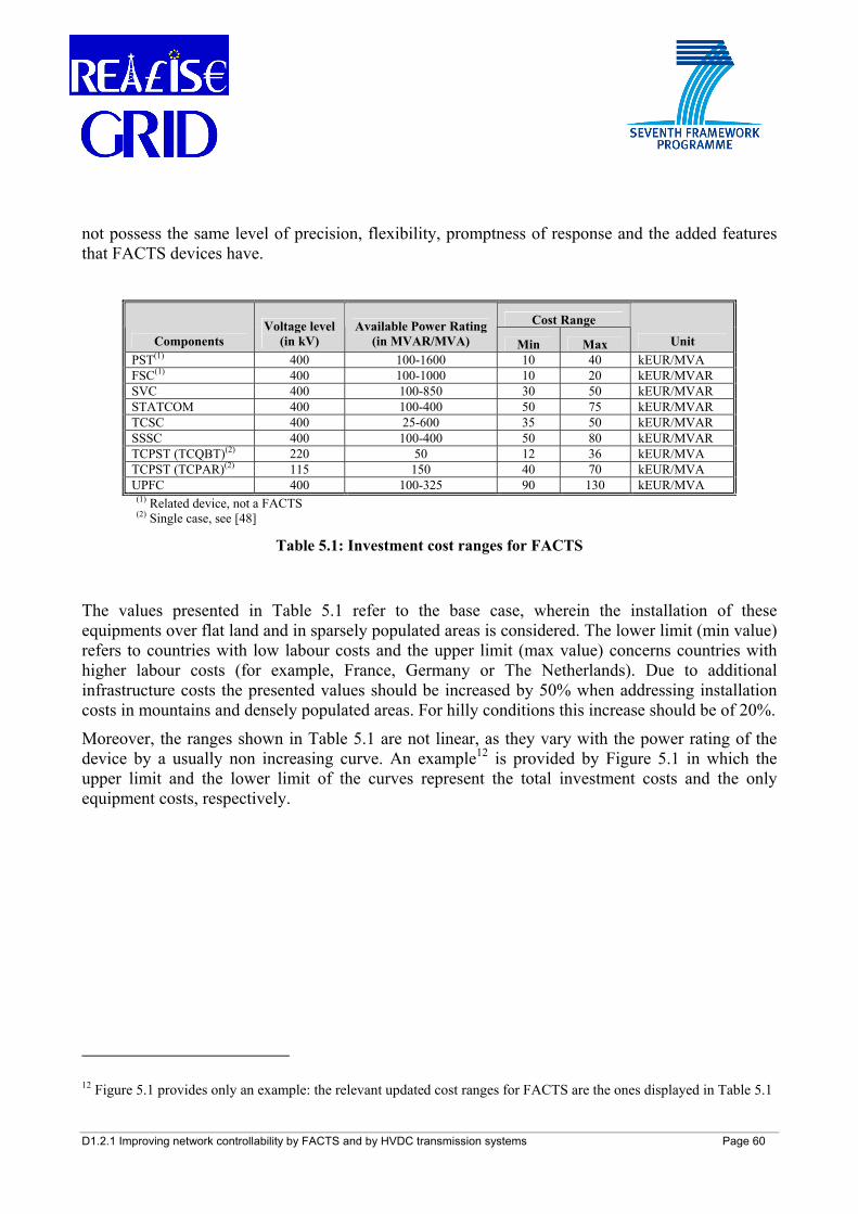
D1.2.1 Improving network controllability by FACTS and by HVDC transmission systems Page 60
not possess the same level of precision, flexibility, promptness of response and the added features that FACTS devices have.
Cost Range
Components Voltage level
(in kV) Available Power Rating
(in MVAR/MVA) Min Max Unit PST(1) 400 100-1600 10 40 kEUR/MVA FSC(1) 400 100-1000 10 20 kEUR/MVAR SVC 400 100-850 30 50 kEUR/MVAR STATCOM 400 100-400 50 75 kEUR/MVAR TCSC 400 25-600 35 50 kEUR/MVAR SSSC 400 100-400 50 80 kEUR/MVAR TCPST (TCQBT)(2) 220 50 12 36 kEUR/MVA TCPST (TCPAR)(2) 115 150 40 70 kEUR/MVA UPFC 400 100-325 90 130 kEUR/MVA
(1) Related device, not a FACTS (2) Single case, see [48]
Table 5.1: Investment cost ranges for FACTS
The values presented in Table 5.1 refer to the base case, wherein the installation of these equipments over flat land and in sparsely populated areas is considered. The lower limit (min value) refers to countries with low labour costs and the upper limit (max value) concerns countries with higher labour costs (for example, France, Germany or The Netherlands). Due to additional infrastructure costs the presented values should be increased by 50% when addressing installation costs in mountains and densely populated areas. For hilly conditions this increase should be of 20%.
Moreover, the ranges shown in Table 5.1 are not linear, as they vary with the power rating of the device by a usually non increasing curve. An example12 is provided by Figure 5.1 in which the upper limit and the lower limit of the curves represent the total investment costs and the only equipment costs, respectively.
12 Figure 5.1 provides only an example: the relevant updated cost ranges for FACTS are the ones displayed in Table 5.1
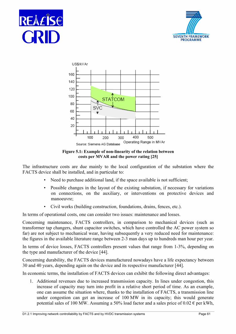
D1.2.1 Improving network controllability by FACTS and by HVDC transmission systems Page 61
Figure 5.1: Example of non-linearity of the relation between
costs per MVAR and the power rating [25]
The infrastructure costs are due mainly to the local configuration of the substation where the FACTS device shall be installed, and in particular to:
• Need to purchase additional land, if the space available is not sufficient;
• Possible changes in the layout of the existing substation, if necessary for variations on connections, on the auxiliary, or interventions on protective devices and manoeuvre;
• Civil works (building construction, foundations, drains, fences, etc.).
In terms of operational costs, one can consider two issues: maintenance and losses.
Concerning maintenance, FACTS controllers, in comparison to mechanical devices (such as transformer tap changers, shunt capacitor switches, which have controlled the AC power system so far) are not subject to mechanical wear, having subsequently a very reduced need for maintenance: the figures in the available literature range between 2-3 man days up to hundreds man hour per year.
In terms of device losses, FACTS controllers present values that range from 1-3%, depending on the type and manufacturer of the device [44].
Concerning durability, the FACTS devices manufactured nowadays have a life expectancy between 30 and 40 years, depending again on the device and its respective manufacturer [44].
In economic terms, the installation of FACTS devices can exhibit the following direct advantages:
1. Additional revenues due to increased transmission capacity. In lines under congestion, this increase of capacity may turn into profit in a relative short period of time. As an example, one can assume the situation where, thanks to the installation of FACTS, a transmission line under congestion can get an increase of 100 MW in its capacity; this would generate potential sales of 100 MW. Assuming a 50% load factor and a sales price of 0.02 € per kWh,
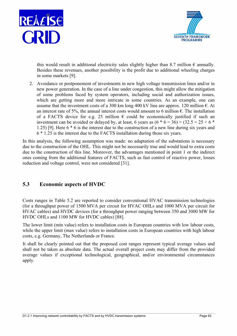
D1.2.1 Improving network controllability by FACTS and by HVDC transmission systems Page 62
this would result in additional electricity sales slightly higher than 8.7 million € annually. Besides these revenues, another possibility is the profit due to additional wheeling charges in some markets [9].
2. Avoidance or postponement of investments in new high voltage transmission lines and/or in new power generation. In the case of a line under congestion, this might allow the mitigation of some problems faced by system operators, including social and authorization issues, which are getting more and more intricate in some countries. As an example, one can assume that the investment costs of a 300 km long 400 kV line are approx. 120 million €. At an interest rate of 5%, the annual interest costs would amount to 6 million €. The installation of a FACTS device for e.g. 25 million € could be economically justified if such an investment can be avoided or delayed by, at least, 6 years as (6 * 6 = 36) > (32.5 = 25 + 6 * 1.25) [9]. Here 6 * 6 is the interest due to the construction of a new line during six years and 6 * 1.25 is the interest due to the FACTS installation during those six years.
In this analysis, the following assumption was made: no adaptation of the substations is necessary due to the construction of the OHL. This might not be necessarily true and would lead to extra costs due to the construction of this line. Moreover, the advantages mentioned in point 1 or the indirect ones coming from the additional features of FACTS, such as fast control of reactive power, losses reduction and voltage control, were not considered [31].
5.3 Economic aspects of HVDC
Costs ranges in Table 5.2 are reported to consider conventional HVAC transmission technologies (for a throughput power of 1500 MVA per circuit for HVAC OHLs and 1000 MVA per circuit for HVAC cables) and HVDC devices (for a throughput power ranging between 350 and 3000 MW for HVDC OHLs and 1100 MW for HVDC cables) [88].
The lower limit (min value) refers to installation costs in European countries with low labour costs, while the upper limit (max value) refers to installation costs in European countries with high labour costs, e.g. Germany, The Netherlands or France.
It shall be clearly pointed out that the proposed cost ranges represent typical average values and shall not be taken as absolute data. The actual overall project costs may differ from the provided average values if exceptional technological, geographical, and/or environmental circumstances apply.
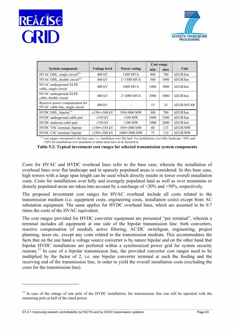
D1.2.1 Improving network controllability by FACTS and by HVDC transmission systems Page 63
Cost range System component Voltage level Power rating min max Unit
HVAC OHL, single circuit(1) 400 kV 1500 MVA 400 700 kEUR/km HVAC OHL, double circuit(1) 400 kV 2×1500 MVA 500 1000 kEUR/km HVAC underground XLPE cable, single circuit 400 kV 1000 MVA 1000 3000 kEUR/km
HVAC underground XLPE cable, double circuit 400 kV 2×1000 MVA 2000 5000 kEUR/km
Reactive power compensation for HVAC cable line, single circuit 400 kV - 15 15 kEUR/MVAR
HVDC OHL, bipolar(1) ±150÷±500 kV 350÷3000 MW 300 700 kEUR/km HVDC underground cable pair ±350 kV 1100 MW 1000 2500 kEUR/km HVDC undersea cable pair ±350 kV 1100 MW 1000 2000 kEUR/km HVDC VSC terminal, bipolar ±150÷±350 kV 350÷1000 MW 60 125 kEUR/MW HVDC CSC terminal, bipolar ±350÷±500 kV 1000÷3000 MW 75 110 kEUR/MW
(1) cost ranges correspond to the base case, i.e. installation over flat land. For installations over hilly landscape +20% and +50% for installations over mountains or urban areas have to be factored in.
Table 5.2: Typical investment cost ranges for selected transmission system components
Costs for HVAC and HVDC overhead lines refer to the base case, wherein the installation of overhead lines over flat landscape and in sparsely populated areas is considered. In this base case, high towers with a large span length can be used which directly results in lower overall installation costs. Costs for installations over hilly and averagely populated land as well as over mountains or densely populated areas are taken into account by a surcharge of +20% and +50%, respectively.
The proposed investment cost ranges for HVAC overhead include all costs related to the transmission medium (i.e. equipment costs, engineering costs, installation costs) except from AC substation equipment. The same applies for HVDC overhead lines, which are assumed to be 0.7 times the costs of the HVAC equivalent.
The cost ranges provided for HVDC converter equipment are presented “per terminal”, wherein a terminal includes all equipment at one side of the bipolar transmission line: both converters, reactive compensation (if needed), active filtering, AC/DC switchgear, engineering, project planning, taxes etc. except any costs related to the transmission medium. This accommodates the facts that on the one hand a voltage source converter is by nature bipolar and on the other hand that bipolar HVDC installations are preferred within a synchronized power grid for system security reasons.13 In case of a bipolar transmission line, the provided converter cost ranges need to be multiplied by the factor of 2, i.e. one bipolar converter terminal at each the feeding and the receiving end of the transmission line, in order to yield the overall installation costs (excluding the costs for the transmission line).
13 In case of the outage of one pole of the HVDC installation, the transmission line can still be operated with the remaining pole at half of the rated power.
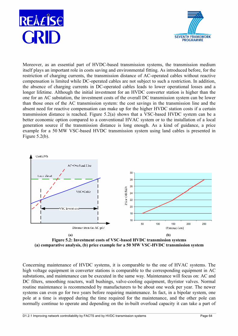
D1.2.1 Improving network controllability by FACTS and by HVDC transmission systems Page 64
Moreover, as an essential part of HVDC-based transmission systems, the transmission medium itself plays an important role in costs saving and environmental fitting. As introduced before, for the restriction of charging currents, the transmission distance of AC-operated cables without reactive compensation is limited while DC-operated cables are not subject to such a restriction. In addition, the absence of charging currents in DC-operated cables leads to lower operational losses and a longer lifetime. Although the initial investment for an HVDC converter station is higher than the one for an AC substation, the investment costs of the overall DC transmission system can be lower than those ones of the AC transmission system: the cost savings in the transmission line and the absent need for reactive compensation can make up for the higher HVDC station costs if a certain transmission distance is reached. Figure 5.2(a) shows that a VSC-based HVDC system can be a better economic option compared to a conventional HVAC system or to the installation of a local generation source if the transmission distance is long enough. As a kind of guidance, a price example for a 50 MW VSC-based HVDC transmission system using land cables is presented in Figure 5.2(b).
(a) (b)
Figure 5.2: Investment costs of VSC-based HVDC transmission systems (a) comparative analysis, (b) price example for a 50 MW VSC-HVDC transmission system
Concerning maintenance of HVDC systems, it is comparable to the one of HVAC systems. The high voltage equipment in converter stations is comparable to the corresponding equipment in AC substations, and maintenance can be executed in the same way. Maintenance will focus on: AC and DC filters, smoothing reactors, wall bushings, valve-cooling equipment, thyristor valves. Normal routine maintenance is recommended by manufacturers to be about one week per year. The newer systems can even go for two years before requiring maintenance. In fact, in a bipolar system, one pole at a time is stopped during the time required for the maintenance, and the other pole can normally continue to operate and depending on the in-built overload capacity it can take a part of
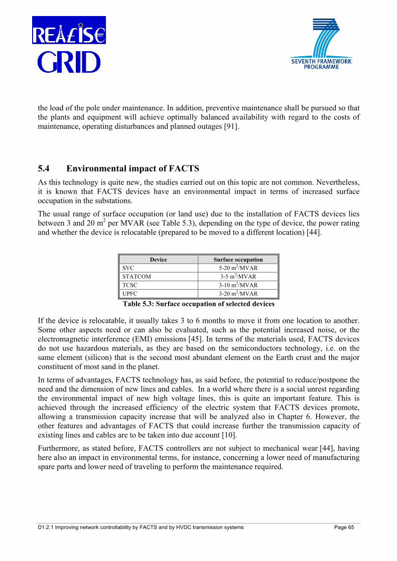
D1.2.1 Improving network controllability by FACTS and by HVDC transmission systems Page 65
the load of the pole under maintenance. In addition, preventive maintenance shall be pursued so that the plants and equipment will achieve optimally balanced availability with regard to the costs of maintenance, operating disturbances and planned outages [91].
5.4 Environmental impact of FACTS As this technology is quite new, the studies carried out on this topic are not common. Nevertheless, it is known that FACTS devices have an environmental impact in terms of increased surface occupation in the substations.
The usual range of surface occupation (or land use) due to the installation of FACTS devices lies between 3 and 20 m2 per MVAR (see Table 5.3), depending on the type of device, the power rating and whether the device is relocatable (prepared to be moved to a different location) [44].
Device Surface occupation SVC 5-20 m2/MVAR STATCOM 3-5 m2/MVAR TCSC 3-10 m2/MVAR UPFC 3-20 m2/MVAR
Table 5.3: Surface occupation of selected devices
If the device is relocatable, it usually takes 3 to 6 months to move it from one location to another. Some other aspects need or can also be evaluated, such as the potential increased noise, or the electromagnetic interference (EMI) emissions [45]. In terms of the materials used, FACTS devices do not use hazardous materials, as they are based on the semiconductors technology, i.e. on the same element (silicon) that is the second most abundant element on the Earth crust and the major constituent of most sand in the planet.
In terms of advantages, FACTS technology has, as said before, the potential to reduce/postpone the need and the dimension of new lines and cables. In a world where there is a social unrest regarding the environmental impact of new high voltage lines, this is quite an important feature. This is achieved through the increased efficiency of the electric system that FACTS devices promote, allowing a transmission capacity increase that will be analyzed also in Chapter 6. However, the other features and advantages of FACTS that could increase further the transmission capacity of existing lines and cables are to be taken into due account [10].
Furthermore, as stated before, FACTS controllers are not subject to mechanical wear [44], having here also an impact in environmental terms, for instance, concerning a lower need of manufacturing spare parts and lower need of traveling to perform the maintenance required.
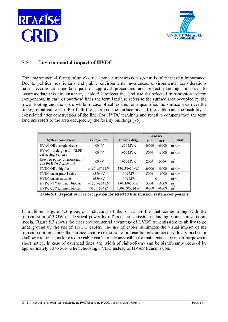
D1.2.1 Improving network controllability by FACTS and by HVDC transmission systems Page 66
5.5 Environmental impact of HVDC
The environmental fitting of an electrical power transmission system is of increasing importance. Due to political restrictions and public environmental awareness, environmental considerations have become an important part of approval procedures and project planning. In order to accommodate this circumstance, Table 5.4 reflects the land use for selected transmission system components. In case of overhead lines the term land use refers to the surface area occupied by the tower footing and the span, while in case of cables this term quantifies the surface area over the underground cable run. For both the span and the surface area of the cable run, the usability is constricted after construction of the line. For HVDC terminals and reactive compensation the term land use refers to the area occupied by the facility buildings [75].
Land use System component Voltage level Power rating min Max Unit
HVAC OHL, single circuit 400 kV 1500 MVA 40000 60000 m2/km HVAC underground XLPE cable, single circuit 400 kV 1000 MVA 5000 15000 m2/km
Reactive power compensation unit for HVAC cable line 400 kV 1000 MVA 2000 3000 m2
HVDC OHL, bipolar ±150..±500 kV 350..3000 MW 20000 40000 m2/km HVDC underground cable ±350 kV 1100 MW 5000 10000 m2/km HVDC undersea cable ±350 kV 1100 MW 0 m2/km HVDC VSC terminal, bipolar ±150..±350 kV 350..1000 MW 5000 10000 m2 HVDC CSC terminal, bipolar ±350..±500 kV 1000..3000 MW 30000 60000 m2
Table 5.4: Typical surface occupation for selected transmission system components
In addition, Figure 5.3 gives an indication of the visual profile that comes along with the transmission of 5 GW of electrical power by different transmission technologies and transmission media. Figure 5.3 shows the clear environmental advantage of HVDC transmission: its ability to go underground by the use of HVDC cables. The use of cables minimizes the visual impact of the transmission line since the surface area over the cable run can be renaturalized with e.g. bushes or shallow root trees, as long as the cable can be made accessible for maintenance or repair purposes at short notice. In case of overhead lines, the width of right-of-way can be significantly reduced by approximately 30 to 50% when choosing HVDC instead of HVAC transmission.
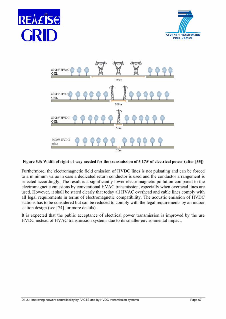
D1.2.1 Improving network controllability by FACTS and by HVDC transmission systems Page 67
Figure 5.3: Width of right-of-way needed for the transmission of 5 GW of electrical power (after [55])
Furthermore, the electromagnetic field emission of HVDC lines is not pulsating and can be forced to a minimum value in case a dedicated return conductor is used and the conductor arrangement is selected accordingly. The result is a significantly lower electromagnetic pollution compared to the electromagnetic emissions by conventional HVAC transmission, especially when overhead lines are used. However, it shall be stated clearly that today all HVAC overhead and cable lines comply with all legal requirements in terms of electromagnetic compatibility. The acoustic emission of HVDC stations has to be considered but can be reduced to comply with the legal requirements by an indoor station design (see [74] for more details).
It is expected that the public acceptance of electrical power transmission is improved by the use HVDC instead of HVAC transmission systems due to its smaller environmental impact.

D1.2.1 Improving network controllability by FACTS and by HVDC transmission systems Page 69
6 PLANNING GUIDELINES FOR THE INTEGRATION OF FACTS AND HVDC INTO MESHED NETWORKS
In general, there are two possible ways to include FACTS and HVDC in the current planning practice of transmission networks: the bottom-up approach and the top-down approach.
The bottom-up approach presented in section 6.1 gives explanations about the advantages and disadvantages of FACTS and HVDC transmission systems, the effects they can have on power system operation and what has to be taken into account during the planning stage of a network expansion process.
The top-down approach in section 6.2 focuses on three typical issues that transmission network planners may be frequently confronted with in the future:
• the need to increase transmission capacity within a section of the power grid;
• the coupling of asynchronously operated networks;
• the connection of offshore wind parks to the main grid.
Schematic flow diagrams, which offer support to select a basic list of possible technical solutions to the most urging issue of the above stated ones (i.e., the need to increase transmission capacity), are presented. It shall be clearly stated that the provided list of possible technical solutions needs to be then further investigated and proved by network studies based on the actual grid configuration. Within this framework, the different technological, economic, and environmental criteria to address each specific problem have to be taken into due account.
Some practical examples of potential applications of FACTS and HVDC in the European power system are finally reported in section 6.3.
6.1 Bottom-up approach 6.1.1 Potential of FACTS towards power system development As seen in Chapter 3, FACTS devices are able to provide some crucial features for the planning and operation of transmission networks, such as power flow and voltage control, very fast response to dynamic issues, and congestion relief, thereby making these networks more reliable, more controllable and more efficient. Furthermore, they can offer the possibility of controlling fluctuating energy sources (e.g. wind power plants) and thereby facilitate their integration into the system.
The improved control of the reactive power flow relates to a major advantage of increasing transmission capacity through the use of FACTS devices. This feature allows a decreased usage of the line by the reactive power, freeing active power capacity. The rapid response of FACTS also permits that the stability limit approaches the thermal limit, which in turn allows a higher capacity of transmission of active power in the line (see Figure 6.1).
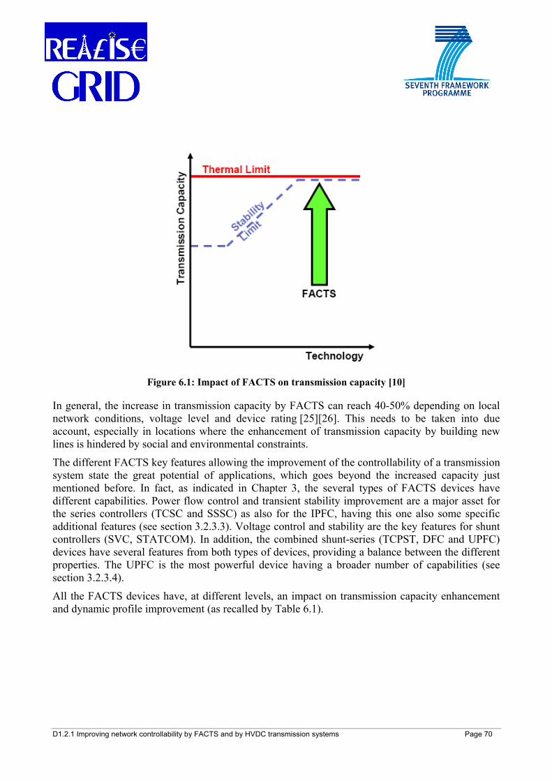
D1.2.1 Improving network controllability by FACTS and by HVDC transmission systems Page 70
Figure 6.1: Impact of FACTS on transmission capacity [10]
In general, the increase in transmission capacity by FACTS can reach 40-50% depending on local network conditions, voltage level and device rating [25][26]. This needs to be taken into due account, especially in locations where the enhancement of transmission capacity by building new lines is hindered by social and environmental constraints.
The different FACTS key features allowing the improvement of the controllability of a transmission system state the great potential of applications, which goes beyond the increased capacity just mentioned before. In fact, as indicated in Chapter 3, the several types of FACTS devices have different capabilities. Power flow control and transient stability improvement are a major asset for the series controllers (TCSC and SSSC) as also for the IPFC, having this one also some specific additional features (see section 3.2.3.3). Voltage control and stability are the key features for shunt controllers (SVC, STATCOM). In addition, the combined shunt-series (TCPST, DFC and UPFC) devices have several features from both types of devices, providing a balance between the different properties. The UPFC is the most powerful device having a broader number of capabilities (see section 3.2.3.4).
All the FACTS devices have, at different levels, an impact on transmission capacity enhancement and dynamic profile improvement (as recalled by Table 6.1).
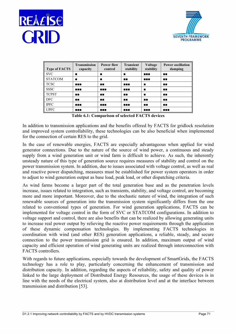
D1.2.1 Improving network controllability by FACTS and by HVDC transmission systems Page 71
Type of FACTS Transmission
capacity Power flow
control Transient stability
Voltage stability
Power oscillation damping
SVC ■ ■ ■ ■■■ ■■ STATCOM ■ ■ ■■ ■■■ ■■ TCSC ■■■ ■■ ■■■ ■ ■■ SSSC ■■■ ■■■ ■■■ ■ ■■ TCPST ■■ ■■ ■■ ■ ■■ DFC ■■ ■■ ■■ ■■ ■■ IPFC ■■■ ■■■ ■■■ ■■ ■■ UPFC ■■■ ■■■ ■■■ ■■■ ■■■
Table 6.1: Comparison of selected FACTS devices
In addition to transmission applications and the benefits offered by FACTS for gridlock resolution and improved system controllability, these technologies can be also beneficial when implemented for the connection of certain RES to the grid.
In the case of renewable energies, FACTS are especially advantageous when applied for wind generator connections. Due to the nature of the source of wind power, a continuous and steady supply from a wind generation unit or wind farm is difficult to achieve. As such, the inherently unsteady nature of this type of generation source requires measures of stability and control on the power transmission system. In addition, due to issues associated with voltage control, as well as real and reactive power dispatching, measures must be established for power system operators in order to adjust to wind generation output as base load, peak load, or other dispatching criteria.
As wind farms become a larger part of the total generation base and as the penetration levels increase, issues related to integration, such as transients, stability, and voltage control, are becoming more and more important. Moreover, due to the stochastic nature of wind, the integration of such renewable sources of generation into the transmission system significantly differs from the one related to conventional types of generation. For wind generation applications, FACTS can be implemented for voltage control in the form of SVC or STATCOM configurations. In addition to voltage support and control, there are also benefits that can be realized by allowing generating units to increase real power output by relieving the reactive power requirements through the application of these dynamic compensation technologies. By implementing FACTS technologies in coordination with wind (and other RES) generation applications, a reliable, steady, and secure connection to the power transmission grid is ensured. In addition, maximum output of wind capacity and efficient operation of wind generating units are realized through interconnection with FACTS controllers.
With regards to future applications, especially towards the development of SmartGrids, the FACTS technology has a role to play, particularly concerning the enhancement of transmission and distribution capacity. In addition, regarding the aspects of reliability, safety and quality of power linked to the large deployment of Distributed Energy Resources, the usage of these devices is in line with the needs of the electrical system, also at distribution level and at the interface between transmission and distribution [53].
D1.2.1 Improving network controllability by FACTS and by HVDC transmission systems Page 72
Furthermore, regarding the SmartGrids objective of strengthening the electrical grid and in the deployment of variable large scale generation [54], the possibility of FACTS devices to give an almost instantaneous response to system disturbances is a major asset, as also described above.
It can be stated that the impact of this technology as part of the road path towards the European energy policy objectives cannot be seen as negligible. This can be understood by several European policy documents, e.g. in the Guidelines for Trans-European Networks for Electricity (TEN-E) [50] that state (Article 3-4):
“The Community shall promote the interconnection, interoperability and development of trans-European energy networks and access to such networks in accordance with Community law in force, with the aim of:
(a) Encouraging the effective operation and development of the internal market in general and of the internal energy market in particular, while encouraging the rational production, transportation, distribution and use of energy resources and the development and connection of renewable energy resources, so as to reduce the cost of energy to the consumer and contribute to the diversification of energy sources; [...]
(c) Reinforcing the security of energy supplies, [...];
(d) Contributing to sustainable development and protection of the environment, inter alia by involving renewable energies and reducing the environmental risks associated with the transportation and transmission of energy.”;
“The priorities for action by the Community on trans-European energy networks shall be compatible with sustainable development and shall be as follows:
1. for both electricity and gas networks:
(a) Adapting and developing the energy networks in support of the operation of the internal energy market and, in particular, solving the problems of bottlenecks, […], congestion and missing links, […]
2. for electricity networks:
(a) Adapting and developing networks to facilitate the integration and connection of renewable energy production […]”
Moreover, towards the efficiency targets as part of the EU 2020 objectives (so-called 20/20/20) [51], FACTS technologies may represent an effective solution to make power transmission and distribution systems more efficient.
In view of the re-engineering process of the European power system [52] needed to handle the crucial challenges of environmental sustainability, competitiveness and security of energy supply, FACTS devices may have a potential impact and a major role to play.
D1.2.1 Improving network controllability by FACTS and by HVDC transmission systems Page 73
6.1.2 Potential of HVDC towards power system development As a mature technology with more than 50 years of application, CSC-HVDC has been proven to be a reliable and valuable transmission technology which offers several technical advantages over conventional HVAC transmission [16], as described in Chapter 4. Furthermore, although at the time of writing only a small number of VSC-HVDC projects (with certain ratings) have been realized worldwide, conducted research has shown that the integration of VSC-HVDC transmission links into today’s networks can have a positive impact on operation, controllability, and stability of the power grid.
Today, the recent push for increased energy efficiency, the increased need to connect remotely located RES to the load centers and the growing public environmental awareness have a significant impact on the design and construction of electrical power transmission networks. Furthermore, the deregulation of the energy market and the growing cross-border power trade result in an increased need of transmission capacity. Depending on the case-related side conditions, HVDC transmission is able to cope with all these needs and provides a feasible, competitive, flexible, and efficient solution to transmit power under environmental constraints while also contributing to power system stability. Taking the planned France-Spain interconnection line as an example, cross-border congestions frequently occur in both directions and are expected to appear more frequently in the short-medium term: then, the implementation of an HVDC interconnection has been chosen as a feasible option to solve this problem, on the one hand due to its ability to enhance the net transfer capacity and to avoid overloading of the transmission line, and on the other hand due to its clear environmental advantage over conventional HVAC transmission [29].
CSC-HVDC is best suited for the transmission of bulk power over long distances. It therefore represents a feasible solution for the interconnection of power grid zones within the pan-European ENTSO-E14 power grid in order to provide additional transmission capacity for the large-scale cross-border power trade, or for the transmission of wind power from countries with high wind generation and low load to power importing countries. Another potential application of CSC-HVDC is the reinforcement of the B2B couplings between the still asynchronously operated power grids of ENTSO-E (i.e. the formerly unaffiliated European power grids ATSOI, BALTSO, NORDEL, UCTE, and UKTSOA) where additional transmission capacity is desirable for further promoting the cross-border power trade. The usability of CSC-HVDC in order to form a MTDC power grid is limited (see section 4.2.6).
VSC-HVDC is useful for the interconnection of remote offshore wind farms to the main power grid since VSC-HVDC is not dependent on a specified ESCR or on reactive power support at the connection points in order to perform a reliable commutation process. Furthermore, its independency of external commutation enables VSC-HVDC to perform a black start which helps TSOs to overcome the problem of how to start-up connected offshore wind farms and to re-energize
14 ENTSO-E: European Network of Transmission System Operators of Electricity. It is the newly created association of TSOs in Europe comprising the former groups of TSOs of UCTE (for continental Europe), NORDEL (for Scandinavian countries), BALTSO (for Baltic countries), UKTSOA (for UK), ATSOI (for Ireland). These correspond to different power systems areas that being not synchronized, when interconnected, are interlinked each other via HVDC links.
D1.2.1 Improving network controllability by FACTS and by HVDC transmission systems Page 74
network sections that suffered from a system blackout. VSC-HVDC can provide additional capacity for the point-to-point power transmission over short- to medium-long distances within a power grid while also providing fast reactive power flow and voltage control at its terminals and thereby contributing to power system and voltage stability. For all these features VSC-HVDC is the most promising technology for MTDC applications and also for forming the backbone of potential offshore grids (like the one in the North Sea) implementation.
Since the amount of active power transmitted over an HVDC link can be set by converter control and is thus not subject to the current network topology or system load (as it is in case of conventional AC transmission), HVDC provides a transfer corridor of fixed power rating at all times during network operation which is especially beneficial during network disturbances. Hence, neighbouring conventional HVAC transmission lines will only be needed to carry the power surplus flowing through the considered network section. Furthermore, while VSC-HVDC is able to directly inject reactive power into a network node, this reactive power is no longer transported to the considered network node through neighbouring AC transmission lines. This frees transmission capacity in the vicinity of the considered network node which was formerly occupied by reactive power and can now be used for active power transmission. Therefore, the positive effect of a VSC-HVDC transmission line on neighbouring network paths has to be taken into account by power flow analyses in order to perform a complete economic assessment.
Both CSC-HVDC and VSC-HVDC are able to use cables as transmission medium with no limitation in cable line length and no need for reactive power compensation. This feature offers the environmental advantage of taking the transmission line underground. VSC-HVDC with underground cabling schemes is also a suitable option for power in-feed of urban areas and cities.
In combination with a wide-area monitoring system, HVDC provides the following features: the fast modulation of active power injection at the HVDC terminals can be used to damp power oscillations within the power grid while (in case of VSC-HVDC) the ability to provide for reactive power flow and voltage control at the terminals has a positive effect on voltage stability. Both directly contribute to the overall power system stability, especially during network disturbances. Further details on wide-area monitoring and control will be treated in REALISEGRID Deliverable D1.2.2.
D1.2.1 Improving network controllability by FACTS and by HVDC transmission systems Page 75
6.2 Top-down approach Considering the different features of FACTS and HVDC, a top-down approach is presented here in order to support transmission planners in their decision-making process addressing the specific issues that TSOs have to deal with.
Table 6.2 [10][11] provides useful information for different static and dynamic applications in which FACTS and HVDC may represent an attractive solution for transmission planning issues, especially for a tightly meshed system like the one in continental Europe: each network condition needs then to be thoroughly evaluated and the different economic and environmental benefits and costs weighed.
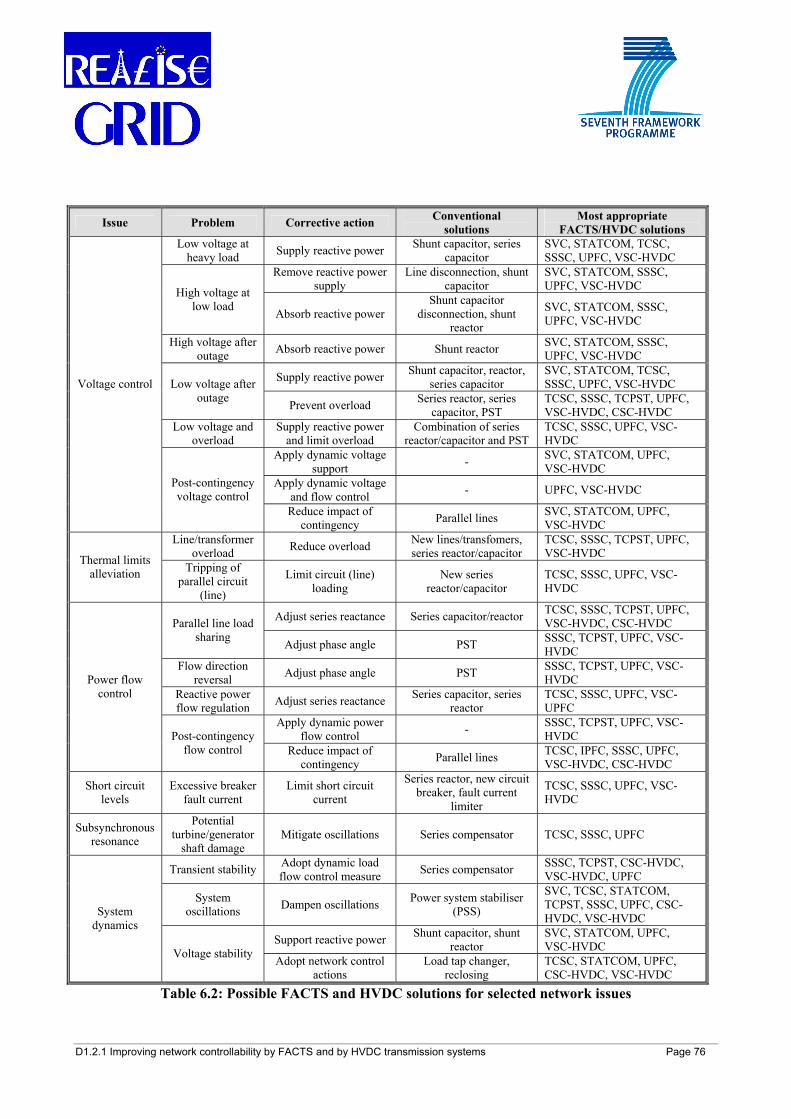
D1.2.1 Improving network controllability by FACTS and by HVDC transmission systems Page 76
Issue Problem Corrective action Conventional solutions
Most appropriate FACTS/HVDC solutions
Low voltage at heavy load Supply reactive power Shunt capacitor, series
capacitor SVC, STATCOM, TCSC, SSSC, UPFC, VSC-HVDC
Remove reactive power supply
Line disconnection, shunt capacitor
SVC, STATCOM, SSSC, UPFC, VSC-HVDC High voltage at
low load Absorb reactive power Shunt capacitor
disconnection, shunt reactor
SVC, STATCOM, SSSC, UPFC, VSC-HVDC
High voltage after outage Absorb reactive power Shunt reactor SVC, STATCOM, SSSC,
UPFC, VSC-HVDC
Supply reactive power Shunt capacitor, reactor, series capacitor
SVC, STATCOM, TCSC, SSSC, UPFC, VSC-HVDC Low voltage after
outage Prevent overload Series reactor, series capacitor, PST
TCSC, SSSC, TCPST, UPFC, VSC-HVDC, CSC-HVDC
Low voltage and overload
Supply reactive power and limit overload
Combination of series reactor/capacitor and PST
TCSC, SSSC, UPFC, VSC-HVDC
Apply dynamic voltage support - SVC, STATCOM, UPFC,
VSC-HVDC Apply dynamic voltage
and flow control - UPFC, VSC-HVDC
Voltage control
Post-contingency voltage control
Reduce impact of contingency Parallel lines SVC, STATCOM, UPFC,
VSC-HVDC Line/transformer
overload Reduce overload New lines/transfomers, series reactor/capacitor
TCSC, SSSC, TCPST, UPFC, VSC-HVDC Thermal limits
alleviation Tripping of parallel circuit
(line)
Limit circuit (line) loading
New series reactor/capacitor
TCSC, SSSC, UPFC, VSC-HVDC
Adjust series reactance Series capacitor/reactor TCSC, SSSC, TCPST, UPFC, VSC-HVDC, CSC-HVDC Parallel line load
sharing Adjust phase angle PST SSSC, TCPST, UPFC, VSC-HVDC
Flow direction reversal Adjust phase angle PST SSSC, TCPST, UPFC, VSC-
HVDC Reactive power flow regulation Adjust series reactance Series capacitor, series
reactor TCSC, SSSC, UPFC, VSC-UPFC
Apply dynamic power flow control - SSSC, TCPST, UPFC, VSC-
HVDC
Power flow control
Post-contingency flow control Reduce impact of
contingency Parallel lines TCSC, IPFC, SSSC, UPFC, VSC-HVDC, CSC-HVDC
Short circuit levels
Excessive breaker fault current
Limit short circuit current
Series reactor, new circuit breaker, fault current
limiter
TCSC, SSSC, UPFC, VSC-HVDC
Subsynchronous resonance
Potential turbine/generator
shaft damage Mitigate oscillations Series compensator TCSC, SSSC, UPFC
Transient stability Adopt dynamic load flow control measure Series compensator SSSC, TCPST, CSC-HVDC,
VSC-HVDC, UPFC
System oscillations Dampen oscillations Power system stabiliser
(PSS)
SVC, TCSC, STATCOM, TCPST, SSSC, UPFC, CSC-HVDC, VSC-HVDC
Support reactive power Shunt capacitor, shunt reactor
SVC, STATCOM, UPFC, VSC-HVDC
System dynamics
Voltage stability Adopt network control actions
Load tap changer, reclosing
TCSC, STATCOM, UPFC, CSC-HVDC, VSC-HVDC
Table 6.2: Possible FACTS and HVDC solutions for selected network issues
D1.2.1 Improving network controllability by FACTS and by HVDC transmission systems Page 77
In the following subsections, after a short introduction on transmission planning processes, general planning guidelines to address specific issues, such as transmission congestion relief, asynchronous systems interconnection and offshore windfarm connection, are provided.
6.2.1 Overview on transmission expansion planning Transmission network planning is a very complex process and recent trends and challenges make it even more complicated. These aspects have been duly highlighted also in REALISEGRID Deliverable D3.1.1 [92] and in the technical literature.
In the past, before the electricity market liberalisation, in a centrally managed power system the system operator could in general control the whole power system: the transmission network was then expanded with the aim to minimise both generation and transmission costs, while meeting static and dynamic technical constraints to ensure a secure and economically efficient operation.
Nowadays, in a liberalised environment, the TSO, responsible for the sole transmission, shall plan the expansion of its network by minimising transmission costs (investment and operation), overcome bottlenecks and pursuing maximum social welfare, when requested by specific regulation, while meeting static and dynamic technical constraints to ensure a secure and economically efficient operation. Socio-environmental constraints must also more and more be duly taken into account in the planning process.
The basic tasks of transmission grid planners can be summarised as in the following: to forecast the power and energy flows on the transmission network, drawing upon a set of scenarios of generation/demand evolution for the targeted period, within the market and regulatory framework; to check whether or not acceptable technical limits might be exceeded within the unchanged network, in standard conditions as well as in case of loss of system components (static/dynamic security analysis); to devise, in presence of criticalities, a set of possible transmission reinforcements/strategies that overcome the constraints and to select the one(s) having the best cost-benefit performance [92][93]. In the following, the different transmission planning aspects are considered and evaluated from the TSO viewpoint at the stage following the static/dynamic security analysis implementation: if network criticalities emerge, a set of possible reinforcements/solutions needs to be selected before a more detailed techno-economic and environmental analysis is performed.
6.2.2 Planning guidelines for transmission congestion relief and capacity enhancement
6.2.2.1 Shifting of power inside the network
The starting point of the selection of the possible candidate network reinforcement within the power grid extension process (see Figure 6.2) is the outcome of a security analysis carried out by probabilistic load flow: this reveals the congested network area which leads to the identification of overloaded transmission lines. In the second step, to solve the issue, it has to be clarified to which extent free capacity on the investigated area ties can be utilized in order to relief the network congestion. If there is not enough free transmission capacity available or if the considered network area is already highly loaded or if the installation of a FACTS device may not lead to the targeted
D1.2.1 Improving network controllability by FACTS and by HVDC transmission systems Page 78
power transfer, the increase of additional transmission capacity within the network zone (i.e. in general the construction of new transmission links) becomes necessary in order to increase the overall transmission capacity of the network section. In case there is enough free transmission capacity available, the shifting of active power to other lines inside the system by a FACTS device should be considered before the construction of new lines: the scope is then to efficiently utilize the given network topology as well as to reduce the economic expenditure and the environmental impact that come along with a physical network expansion. A FACTS device suitable for efficient power flow shifting, as described in Chapter 3, could be installed in one of the substations of the overloaded transmission line. Generally, the installation of multiple neighbouring FACTS devices for shifting the active power surplus to a number of available capacity paths is only feasible if a coordinating control is applied in order to avoid mutual interference between the power flow controllers (these issues will be treated in REALISEGRID Deliverable D1.2.2 “Improving network controllability by coordinated control of HVDC and FACTS devices”).
For a continuous congestion of moderate order of magnitude, the installation of a static device (such as a series capacitor, a series reactor, a TSSC, or a TSSR) may constitute a feasible solution to solve the power flow bottleneck. In cases where the congestion is discontinuous, the application of dynamic devices may be advantageous since these devices are able to monitor the power flow on a transmission line and to limit this power flow to a permitted value when needed. Consequently, they release when the power flow on the considered transmission line returns to normal values which can be independently handled by the transmission line. For a congestion that is associated with a relatively low degree of volatility, slow-switching devices (such as a PST) can be feasible while in case of a relatively high degree of volatility fast-adjusting devices (such as a TCSC, SSSC, UPFC or HVDC back-to-back installation) present possible solutions.
In general, the construction of shunt connected FACTS devices like SVC or STATCON does not directly improve transmission capacity significantly. These devices provide local reactive power compensation. In situations when local reactive power supply is insufficient the transmission grid is used to transport reactive power from other sources. This reactive power transmission reduces the available capacity for active power transmission on affected lines. By providing local reactive power compensation less reactive power needs to be transported through the grid leading to a slightly increase of available transmission capacity. Per contra, other FACTS devices, namely series devices and the combined devices, as they adjust line reactance and series control, do directly improve transmission capacity at significant levels, as stated in Chapter 3, and are a solution whose technical and economic feasibility should be assessed to solve this type of situations. Also, the installation of FACTS able to control more parameters at the same time (for example, power flow control and voltage amplitude) can be very beneficial for solving more than a problem at the same time.
Nevertheless, with the application of FACTS devices the (n-1) security analysis needs to be reviewed for each case: FACTS devices change the naturally set load distribution that (in the above considered cases) includes overloaded transmission lines. These overloaded transmission lines will reappear if the FACTS device fails which in turn may lead to an instability of the overall power grid. Therefore, the counteractions to an extemporaneous malfunction of these FACTS devices have to be considered by a network security analysis which strongly depends on the specific network topology and the TSOs degree of conservation.
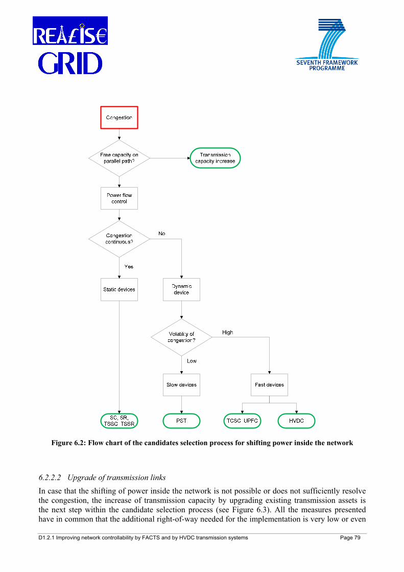
D1.2.1 Improving network controllability by FACTS and by HVDC transmission systems Page 79
Figure 6.2: Flow chart of the candidates selection process for shifting power inside the network
6.2.2.2 Upgrade of transmission links
In case that the shifting of power inside the network is not possible or does not sufficiently resolve the congestion, the increase of transmission capacity by upgrading existing transmission assets is the next step within the candidate selection process (see Figure 6.3). All the measures presented have in common that the additional right-of-way needed for the implementation is very low or even
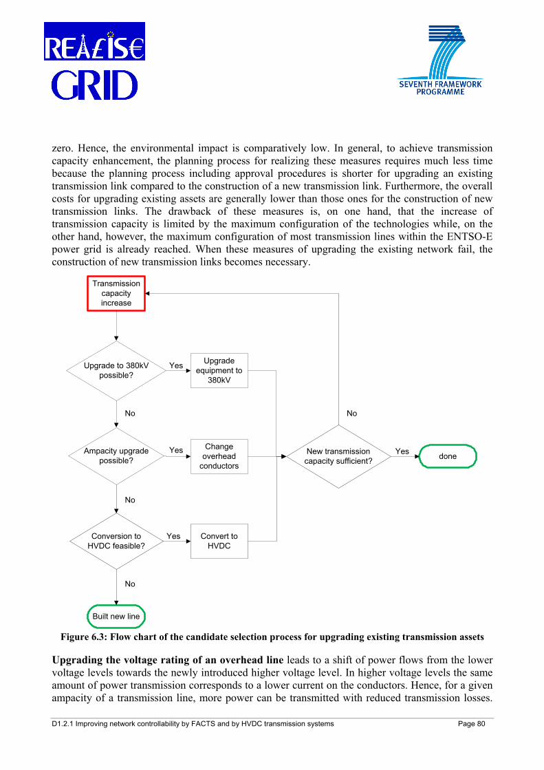
D1.2.1 Improving network controllability by FACTS and by HVDC transmission systems Page 80
zero. Hence, the environmental impact is comparatively low. In general, to achieve transmission capacity enhancement, the planning process for realizing these measures requires much less time because the planning process including approval procedures is shorter for upgrading an existing transmission link compared to the construction of a new transmission link. Furthermore, the overall costs for upgrading existing assets are generally lower than those ones for the construction of new transmission links. The drawback of these measures is, on one hand, that the increase of transmission capacity is limited by the maximum configuration of the technologies while, on the other hand, however, the maximum configuration of most transmission lines within the ENTSO-E power grid is already reached. When these measures of upgrading the existing network fail, the construction of new transmission links becomes necessary.
Figure 6.3: Flow chart of the candidate selection process for upgrading existing transmission assets
Upgrading the voltage rating of an overhead line leads to a shift of power flows from the lower voltage levels towards the newly introduced higher voltage level. In higher voltage levels the same amount of power transmission corresponds to a lower current on the conductors. Hence, for a given ampacity of a transmission line, more power can be transmitted with reduced transmission losses.
Transmission capacity increase
Upgrade to 380kV possible?
Upgrade equipment to
380kV
Ampacity upgrade possible?
Conversion to HVDC feasible?
Change overhead
conductors
Convert to HVDC
New transmission capacity sufficient?
Built new line
done
Yes
No
Yes
Yes
No
No
Yes
No
D1.2.1 Improving network controllability by FACTS and by HVDC transmission systems Page 81
The transmission grid in Europe is mainly based on assets at the voltage levels of 220 kV and 380 kV. Uprating 220 kV assets to a voltage level of 380 kV increases the transmission capacity of the line but generally requires new transmission towers with a larger surface occupation and a larger width of right-of-way. This leads to an increasing environmental impact and to high installation costs. A trade-off needs to be duly considered. At the time of writing, many TSOs in Europe already upgraded their transmission assets from 220 kV to 380 kV wherever possible so that this option may have already become outdated.
Introducing a new voltage layer into the European transmission grid with voltages above 400 kV requires significant changes within the power system structure in order to assure an efficient power transport. If power plants remain connected to the 380 kV level, then power flows need to pass through transformers towards the higher voltage level. These transformers increase the total impedance of the transmission path and compensate the advantage of the higher voltage level. Additionally, the power flow through the transmission lines of the lower voltage levels is only slightly reduced. The introduction of very high voltage levels above 400 kV in Europe would require either very long transmission lines or the connection of large power plants to the new voltage level. In Europe there are very few lines at 750 kV level linking the UCTE and the IPS/UPS system (most of them are however currently out of operation). The introduction of a new grid layer with a voltage above 400 kV usually requires the construction of new transmission lines and an enlargement of the surface occupation. This leads to an increasing environmental impact and to very high installation costs. This option is currently not realistic in continental Europe.
For increasing the ampacity of overhead lines either conductors with a larger cross section or High Temperature Low Sag (HTLS) conductors can be used. Conductors with a larger cross section are capable of carrying higher currents and thus transmit more power. Since the ohmic resistance decreases with increasing cross section, losses for transmitting the same amount of power are reduced by using conductors with a larger cross section. On the downside, conductors with a larger cross section have a higher weight and a higher sagging so that such an upgrade may require new towers to carry these conductors. This leads to an increasing environmental impact and to the medium installation costs. A trade-off should be carefully considered. Alternatively, HTLS conductors (also known as HTC, High Temperature Conductors) allow for a higher current density and can therefore carry higher currents compared to conventional conductors at equal cross section. This directly results in a higher power transfer on the line [87]. Ohmic transmission losses between these two conductor types are equal when carrying the same currents but when HTLS conductors carry very high currents (higher than the maximum current limit of conventional conductors) then it leads to very high transmission losses. Therefore, HTLS conductors are only advisable if the transmission line has a low loading during normal operation and is only highly loaded during short periods of time. HTLS conductors have equal profile and equal sagging like conventional conductors and can therefore be installed on existing towers. An additional option could be the combination of the utilisation of HTLS with FACTS in order to further increase transmission capacity and system controllability. The implementation of high temperature conductors replacing conventional conductors is becoming more and more a frequent practice by European TSOs (reconductoring) to increase transmission capacity at congested borders. An example concerns the France-Italy interconnection corridor [87][90].
D1.2.1 Improving network controllability by FACTS and by HVDC transmission systems Page 82
Converting an HVAC overhead line to HVDC constitutes an interesting option for the increase of transmission capacity due to the increased power density for a given width of right-of-way that can be obtained from an HVDC transmission circuit compared to a conventional HVAC transmission circuit [73]. For the conversion of the line, the suitability of the tower geometry and the tower configuration has to be determined, especially with respect to tower cross arm geometry, tower statics, insulator assemblies and conductor configuration. Generally, no change in the tower construction, their foundation and in the conductors is accepted since these major modifications would lead to high investments which would make the conversion economically unfavourable compared to the replacement of the complete line. In any case, insulators need to be changed when converting from HVAC to HVDC as well as additional space needs to be allocated within or at least in the vicinity of the existing substations in order to accommodate the HVDC converters. This leads to limit investment costs and a project execution time within the medium-term horizon. There is usually no need for time-consuming approval procedures since the width of right-of-way is not changed and hence the environmental impact of this HVAC/HVDC conversion is low.
In the case of bulk-power point-to-point transmission (>1500 MW), the choice of which HVDC technology to apply is today limited to CSC-HVDC as the currently available power ratings of VSC-HVDC are still too low. Furthermore, in case of CSC-HVDC, the ESCR of both considered network nodes have to be determined and enforced if necessary (see Chapter 4). However, in the case of power transmission lower than 1100 MW, VSC-HVDC already constitutes a feasible option which provides higher benefits in both environmental impact and network controllability. The future technological developments of VSC-HVDC towards increased power ratings may allow for considering VSC-HVDC as another option for bulk-power transport.
6.2.2.3 Construction of new transmission links
In addition to the above mentioned measures, new transmission links could be required. The following four options are possible:
• HVAC overhead line • HVDC overhead line • HVAC cable • HVDC cable
HVDC overhead lines and cables are able to transmit more power compared to HVAC overhead lines and cables respectively at equal surface occupation. Furthermore, HVDC links provide additional controllability of the power grid which can be used to optimize transmission losses and to reduce the loading of the HVAC grid. An increased level of controllability on a new HVAC link may be achieved by adding a FACTS device on the analysed corridor: this however may lead to higher investments.
HVDC transmission lines can be set to a fixed level of transmitted power. This working point will also be maintained in case of a network disturbance. Therefore, an HVDC link cannot be overloaded due to a disturbance and is inherently safe. This increases the system reliability.
In the case of VSC-HVDC, additional reactive power support at the connection point is provided. Hence, VSC-HVDC helps maintaining a certain voltage profile within a power network. Reactive
D1.2.1 Improving network controllability by FACTS and by HVDC transmission systems Page 83
power transport on neighbouring lines that are connected to the same network node can be reduced. This frees up transmission capacities for active power transport on neighbouring lines. Therefore, when analyzing the potential of an HVDC link in comparison to conventional HVAC, the positive effect of HVDC on neighbouring nodes has to be considered too. Similar effects in terms of reactive power control, voltage support and transmission capacity enhancement can be also achieved by inserting powerful FACTS devices (e.g. UPFC) on the new HVAC link, with the caveat however, as above recalled, of increasing investments.
HVDC allows going underground without a limitation in cable line length since there is no need for reactive compensation. In cases where an HVDC underground solution is technologically and economically feasible, the environmental impact is reduced (compared to a conventional HVAC overhead line). A recent example of this choice is the new France-Spain interconnection.
However, HVDC converters are expensive. High converter costs can be compensated by lower OHL / cable costs and by lower capitalized transmission losses in case of long connections. A trade-off between all gains and costs should then be duly considered.
6.2.3 Planning guidelines for coupling of asynchronous networks Coupling of asynchronous networks is realised by means of HVDC converters. The interconnecting transmission lines can be based either on full HVDC or on HVAC in combination with a HVDC B2B station. The HVDC converter stations can be based either on CSC-HVDC or on VSC-HVDC technology. For each selected corridor, the interconnection of two asynchronous systems can be then carried out by four general options: HVAC+CSC-HVDC B2B, HVAC+VSC-HVDC B2B, full CSC-HVDC, full VSC-HVDC. Depending on the choice of transmission medium type (cable or overhead line) the possible combinations amount to eight at least. Based on each specific situation, local network conditions, geographical and environmental features, the amount of possible options can surely increase. The criteria for deciding between the HVAC and HVDC technologies are similar to the criteria within a meshed HVAC grid. However, some other aspects (like dynamic features) differ between the two cases: dynamic studies results need then to be taken into due account..
When planning the HVDC elements (either in B2B or in full scheme) several parameters have to be taken into account [91]: link length, DC side power and voltage levels (nominal and limits), type of DC connection (monopolar/bipolar) and return conductor, use of DC side switching between poles/bipoles, use of DC side filter, amount of DC converters per pole/bipole, flow reversal requirement, DC converters/system reliability/availability, AC side voltage levels (nominal and limits), AC side frequency levels (nominal and limits), MVA short circuit limits, AC side insulation levels, AC side reactive power generation and absorption limits, AC side temporary overvoltage, AC side harmonics limits, AC side ground connection, all cost elements, auxiliary equipment data, control and telecommunications features and modalities, local ambient and site temperature conditions, geographical/environmental characteristics.
In the ENTSO-E European system, the five electricity networks areas, when interlinked, are currently interconnected each other via full HVDC links: the reason is related to a clear geographical constraint (long sea distance), practically excluding a possibility for HVAC
D1.2.1 Improving network controllability by FACTS and by HVDC transmission systems Page 84
interconnections. There are then HVDC ties interlinking the networks of former UCTE and NORDEL, UCTE and UKTSOA, ATSOI and UKTSOA, NORDEL and BALTSO. The latter interconnection is the only one coupling asynchronous systems in Europe which is based on VSC-HVDC (Estlink, between Estonia, former BALTSO, and Finland, former NORDEL). At the time of writing, only a single HVAC+HVDC B2B station is in operation in the European system, namely the one at the interface between Finland (former NORDEL, ENTSO-E) and Russia (IPS/UPS). The CSC-HVDC B2B station is located at Vyborg busbar in Russia. Until the second half of the 1990s, other three CSC-HVDC B2B stations were in operation at the interface between the then UCPTE and the former CENTREL system. Further asynchronous interconnections [90] are expected at pan-European level in a short-mid term horizon, namely between former BALTSO and NORDEL, UCTE and NORDEL, UCTE and BALTSO. The latter interconnection project (linking Poland and Lithuania, see also 6.3.4.1 [75]) assumes a strategic role being the first link between former UCTE and BALTSO.
6.2.4 Planning guidelines for the connection of offshore wind farms The connection of offshore wind farms to the power grid generally meets two technological challenges: firstly, high amounts of active power have to be transmitted to the power grid since offshore wind farms consist of a large number of wind turbines; secondly, several kilometers of sea route have to be crossed due to the offshore location. Additionally, environmental constraints need to be met, e.g. low surface occupation and low visual impact of the transmission line. Within this framework, an economically reasonable solution needs to be found. Depending on all three factors (technological challenges, environmental constraints and economical framework) one of the following options may constitute a feasible solution for the connection of offshore wind farms to the main power grid: HVAC submarine cable, VSC-HVDC submarine cable, or CSC-HVDC submarine cable (see Figure 6.4).
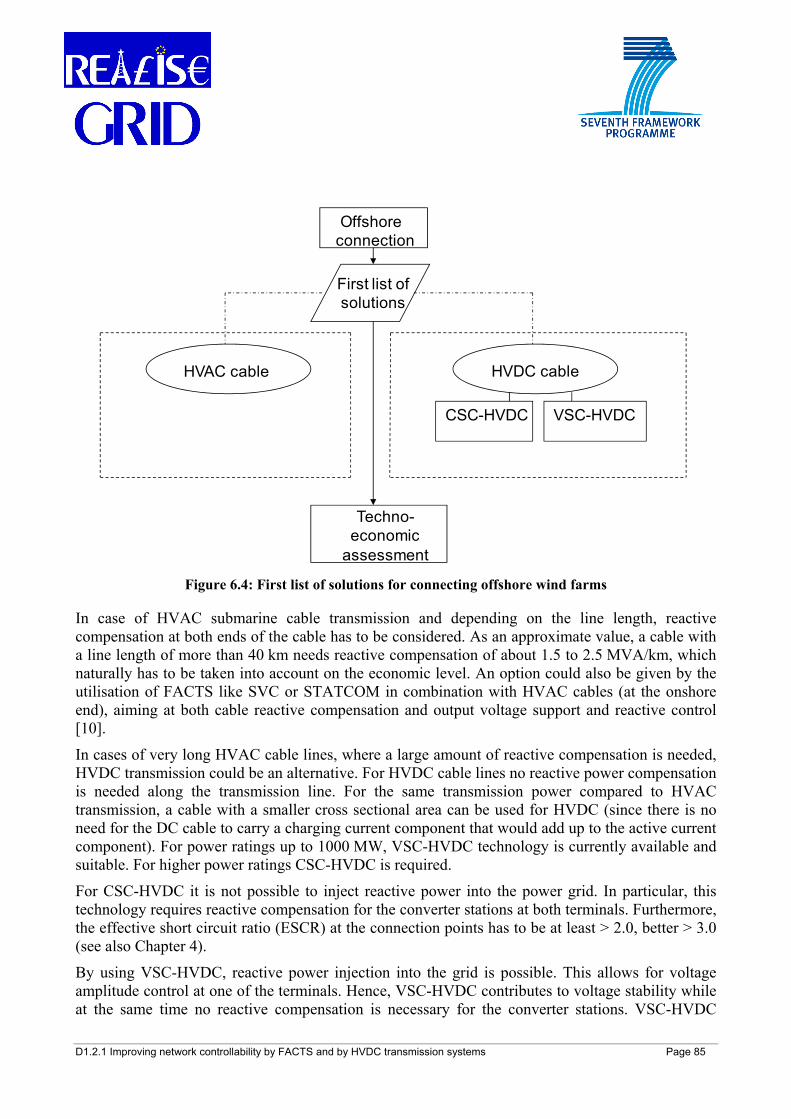
D1.2.1 Improving network controllability by FACTS and by HVDC transmission systems Page 85
Offshore connection
First list of solutions
Techno-economic
assessment
HVAC cable HVDC cable
VSC-HVDCCSC-HVDC
Figure 6.4: First list of solutions for connecting offshore wind farms
In case of HVAC submarine cable transmission and depending on the line length, reactive compensation at both ends of the cable has to be considered. As an approximate value, a cable with a line length of more than 40 km needs reactive compensation of about 1.5 to 2.5 MVA/km, which naturally has to be taken into account on the economic level. An option could also be given by the utilisation of FACTS like SVC or STATCOM in combination with HVAC cables (at the onshore end), aiming at both cable reactive compensation and output voltage support and reactive control [10].
In cases of very long HVAC cable lines, where a large amount of reactive compensation is needed, HVDC transmission could be an alternative. For HVDC cable lines no reactive power compensation is needed along the transmission line. For the same transmission power compared to HVAC transmission, a cable with a smaller cross sectional area can be used for HVDC (since there is no need for the DC cable to carry a charging current component that would add up to the active current component). For power ratings up to 1000 MW, VSC-HVDC technology is currently available and suitable. For higher power ratings CSC-HVDC is required.
For CSC-HVDC it is not possible to inject reactive power into the power grid. In particular, this technology requires reactive compensation for the converter stations at both terminals. Furthermore, the effective short circuit ratio (ESCR) at the connection points has to be at least > 2.0, better > 3.0 (see also Chapter 4).
By using VSC-HVDC, reactive power injection into the grid is possible. This allows for voltage amplitude control at one of the terminals. Hence, VSC-HVDC contributes to voltage stability while at the same time no reactive compensation is necessary for the converter stations. VSC-HVDC
D1.2.1 Improving network controllability by FACTS and by HVDC transmission systems Page 86
provides a faster and smoother control than CSC-HVDC and is suitable for multi-terminal applications. Nevertheless, multi-terminal applications have the hitch that no HVDC circuit breaker is available yet and therefore failure clearing requires tripping of the whole multi-terminal system (see section 4.2.6).
6.3 Examples of FACTS and HVDC applications This section, after introducing some elements necessary for performing cost-benefit analyses of new interconnections options, presents some practical examples of potential applications of FACTS and HVDC to address specific issues in the European power system. Preliminary quantitative results based on [72][75][76] are also displayed in order to select and evaluate the most promising options under certain assumptions in the analysed cases 15.
6.3.1 Cost-benefit analysis of transmission investments Regarding the economic evaluation of an investment project, this requires in general an initial expenditure, which is then gradually recovered by means of the earnings coming from the implemented project. The future revenues have to be discounted according to the expected accumulated inflation and interest rates. In this analysis a fundamental concept is given by the operating cash flow, represented by the revenues generated from operations subtracting the direct and indirect costs, expenses for taxation and interests, investment incomes and dividends paid.
Instead of using FACTS or HVDC technologies, other solutions may envisage the deployment of conventional components, in particular new HVAC lines.
The comparison and prioritisation of alternative solutions is performed via cost-benefit analyses based on the following well known indicators [72]:
• Net Present Value (NPV) of an investment • Internal Rate of Return (IRR) of the invested capital • Profitability Index (PI) of an investment • Pay Back Period (PBP) of an investment
These four indicators are used to techno-economically assess and compare the insertion of FACTS and HVDC with respect to other traditional solutions in the liberalised European power system. Among the economic benefits stemming from an interconnection project between two systems there are the cash revenues calculated as savings derived by an increased cheaper energy flow in the importing power system. These revenues can be expressed in this case in a simple way as
15 As a disclaimer it should be specified that the results presented in the following subsections - also because of the different assumptions, conditions and data considered - may differ from those ones obtained in studies of the relevant stakeholders on the investigated projects.
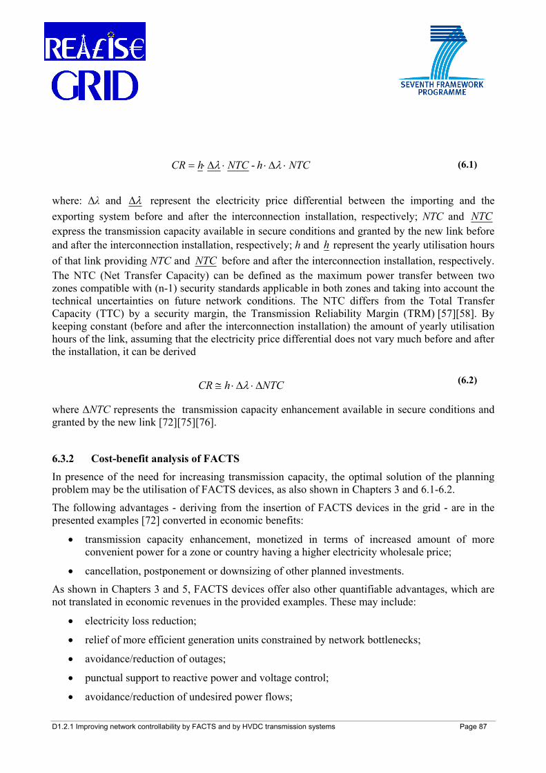
D1.2.1 Improving network controllability by FACTS and by HVDC transmission systems Page 87
where: Δλ and λΔ represent the electricity price differential between the importing and the exporting system before and after the interconnection installation, respectively; NTC and NTC express the transmission capacity available in secure conditions and granted by the new link before and after the interconnection installation, respectively; h and h represent the yearly utilisation hours of that link providing NTC and NTC before and after the interconnection installation, respectively. The NTC (Net Transfer Capacity) can be defined as the maximum power transfer between two zones compatible with (n-1) security standards applicable in both zones and taking into account the technical uncertainties on future network conditions. The NTC differs from the Total Transfer Capacity (TTC) by a security margin, the Transmission Reliability Margin (TRM) [57][58]. By keeping constant (before and after the interconnection installation) the amount of yearly utilisation hours of the link, assuming that the electricity price differential does not vary much before and after the installation, it can be derived
where ΔNTC represents the transmission capacity enhancement available in secure conditions and granted by the new link [72][75][76].
6.3.2 Cost-benefit analysis of FACTS
In presence of the need for increasing transmission capacity, the optimal solution of the planning problem may be the utilisation of FACTS devices, as also shown in Chapters 3 and 6.1-6.2.
The following advantages - deriving from the insertion of FACTS devices in the grid - are in the presented examples [72] converted in economic benefits:
• transmission capacity enhancement, monetized in terms of increased amount of more convenient power for a zone or country having a higher electricity wholesale price;
• cancellation, postponement or downsizing of other planned investments. As shown in Chapters 3 and 5, FACTS devices offer also other quantifiable advantages, which are not translated in economic revenues in the provided examples. These may include:
• electricity loss reduction; • relief of more efficient generation units constrained by network bottlenecks;
• avoidance/reduction of outages; • punctual support to reactive power and voltage control; • avoidance/reduction of undesired power flows;
NTChNTChCR ⋅Δ⋅⋅Δ⋅= λλ - (6.1)
NTChCR Δ⋅Δ⋅≅ λ (6.2)
D1.2.1 Improving network controllability by FACTS and by HVDC transmission systems Page 88
• environmental benefits; • exploitation of RES energy; • system stability enhancement.
Further details about the evaluation of the above listed benefits can be found in REALISEGRID Deliverable D3.3.1 [93].
6.3.3 Cost-benefit analysis of HVDC In case the transmission of a higher level of power between two zones is of concern, a solution may be the deployment of VSC-based HVDC instead of conventional transmission technologies, as also shown in Chapters 4 and 6.1-6.2. Depending on the network features (e.g. adequacy and topology), a new link may offer also the possibility to increasingly exploit more efficient and/or renewable source-based electricity generation spread in the system. This additional capacity can then replace the electricity capacity of less efficient generation (substitution effect) leading to a system CO2 emission reduction. VSC-HVDC can be also used to interconnect asynchronous systems or areas.
The following advantages are quantified in the present analysis [75][76]:
• Transmission capacity enhancement, monetized in terms of increased cheaper energy imported by a zone or country having an averagely higher electricity wholesale price;
• Emissions reduction, as a consequence of the exploitation of more efficient (in particular renewable) electricity generation capacity, quantified in terms of CO2 emissions avoided and monetized in terms of carbon tax savings;
• Surface occupation, evaluated in terms of km2 of land devoted to plants’ right-of ways; • Additional energy exchange secured by fast power flow control devices and monetized in
terms of increased cheaper energy imported by a zone or country with a higher electricity wholesale price.
The latter benefit is achievable by VSC-HVDC links since they can quickly react to steer and control rapid power flow variations also brought about by renewable electricity sources (like wind e.g.).
As seen in Chapters 4-5, VSC-HVDC systems may offer also other advantages, here not quantified, such as: punctual support to reactive power and voltage control; avoidance/reduction of undesired power flows; EMFs (electro-magnetic fields) abatement. Additional benefits, here not monetized, that a network reinforcement may produce are: cancellation, postponement or downsizing of other planned investments; electricity loss reduction; relief of more efficient generation units constrained by network bottlenecks; reduction of energy not supplied after outages; reduction of the amount of generation reserve [75][76][93].
6.3.4 Practical FACTS and HVDC applications in Europe For all investigated potential applications, the reference system is the European transmission grid and the test network (at 400-220 kV) is the one described in [56] suitable for DC studies: it consists
D1.2.1 Improving network controllability by FACTS and by HVDC transmission systems Page 89
of 1254 buses, 378 generators and 1944 lines and conveniently approximates the Continental Europe (former UCTE) network, especially concerning the cross-border flows in winter peak situation. For this system the line capacity limits have been updated with data available from [57]. Cost-benefit analyses have been then based on the results of the simulations (carried out in Matlab®) performed on this European test network.
In addition to the test cases hereinafter presented, several other studies have been carried out for the implementation of FACTS and HVDC in the European power system.
It is worth to outline that FACTS devices have a potential for application in different European systems. In Italy, SVC and STATCON are under consideration for static and dynamic applications, while series and combined controllers might be very useful to relieve congestions in different parts of the system both at internal and cross-border level. In Poland, the different types of FACTS devices might be very effective to manage active and reactive power flow control, voltage regulation and system stability control. In Germany, SVC and series controllers are under consideration, especially for wind integration and power flow control issues [90]. Also in Spain shunt controllers and SSSC device are under study [83].
At general level, the different types of series and combined FACTS devices could provide more effective solutions to the European issues on several cross-border ties than the PSTs there installed actually do.
6.3.4.1 The Poland-Lithuania link
This section investigates the techno-economic and environmental sustainability of building a VSC-HVDC link as an alternative to other conventional technologies, in order to increase the transmission capacity in the liberalised European power system. A VSC-HVDC link, modeled for DC load flow studies, has been inserted in the test network. Simulations have been run to assess the NTC increase granted by a new interconnection line built between two power systems [75]. The results have been then utilised for the calculation of the economic indicators (seen in section 6.3) to compare viability and degree of profitability of the selected options based upon HVAC and HVDC technologies. In addition to the Continental Europe test network (former UCTE system), a part of the interconnected Russian IPS/UPS system, namely the one of the Baltic States Lithuania, Latvia and Estonia (former BALTSO system), has been taken in consideration (see Figure 6.5) [59]. This system, which is operated at 330-220 kV, can be schematically represented by a total of 37 buses, 17 generators and 64 lines (including the interconnections with the other IPS/UPS countries, such as Russia and Belarus, and with Finland via submarine VSC-HVDC link). An equivalent network suitable for DC studies, based on publicly available data [57]-[59], has been utilised for this Baltic grid.
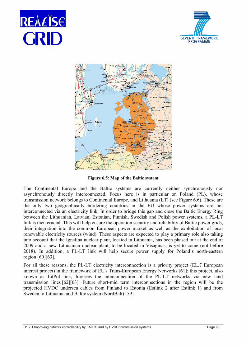
D1.2.1 Improving network controllability by FACTS and by HVDC transmission systems Page 90
Figure 6.5: Map of the Baltic system
The Continental Europe and the Baltic systems are currently neither synchronously nor asynchronously directly interconnected. Focus here is in particular on Poland (PL), whose transmission network belongs to Continental Europe, and Lithuania (LT) (see Figure 6.6). These are the only two geographically bordering countries in the EU whose power systems are not interconnected via an electricity link. In order to bridge this gap and close the Baltic Energy Ring between the Lithuanian, Latvian, Estonian, Finnish, Swedish and Polish power systems, a PL-LT link is then crucial. This will help ensure the operation security and reliability of Baltic power grids, their integration into the common European power market as well as the exploitation of local renewable electricity sources (wind). These aspects are expected to play a primary role also taking into account that the Ignalina nuclear plant, located in Lithuania, has been phased out at the end of 2009 and a new Lithuanian nuclear plant, to be located in Visaginas, is yet to come (not before 2018). In addition, a PL-LT link will help secure power supply for Poland’s north-eastern region [60][63].
For all these reasons, the PL-LT electricity interconnection is a priority project (EL.7 European interest project) in the framework of EU's Trans-European Energy Networks [61]: this project, also known as LitPol link, foresees the interconnection of the PL-LT networks via new land transmission lines [62][63]. Future short-mid term interconnections in the region will be the projected HVDC undersea cables from Finland to Estonia (Estlink 2 after Estlink 1) and from Sweden to Lithuania and Baltic system (NordBalt) [59].
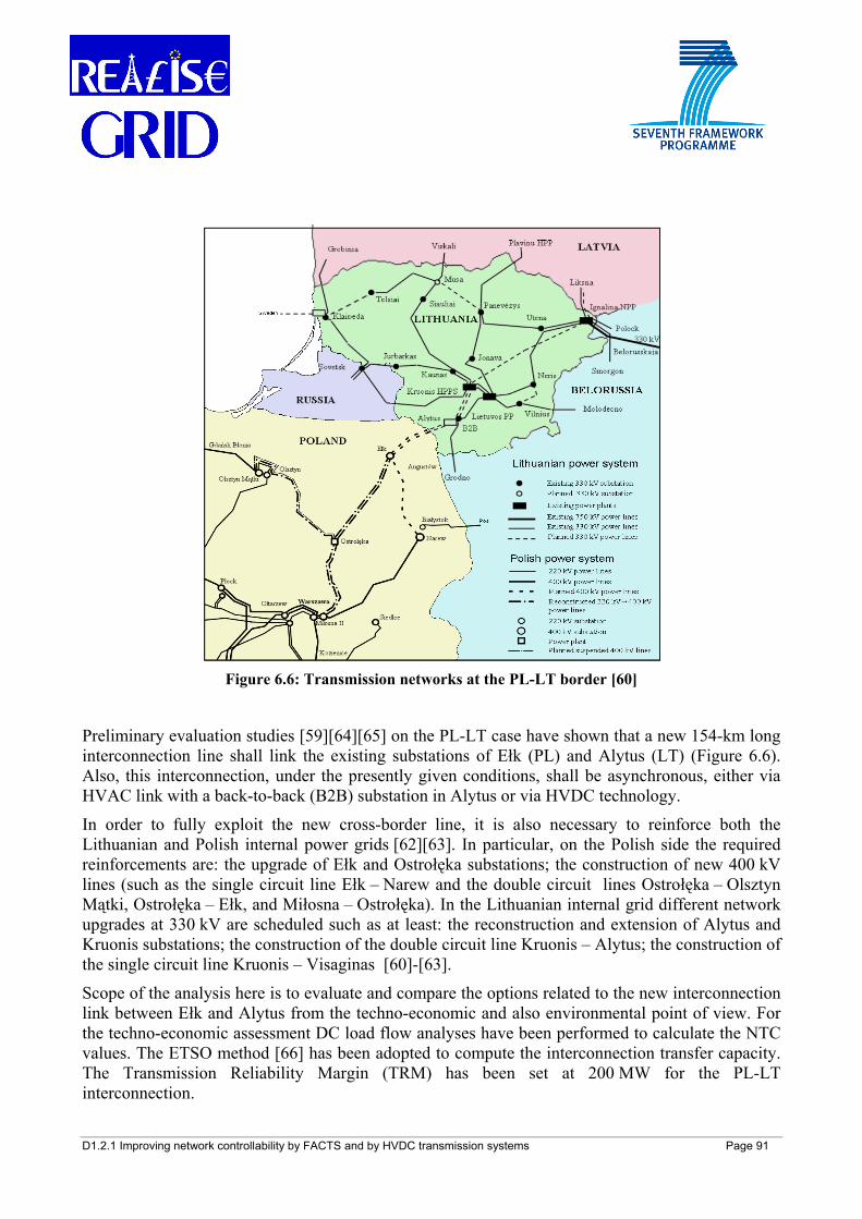
D1.2.1 Improving network controllability by FACTS and by HVDC transmission systems Page 91
Figure 6.6: Transmission networks at the PL-LT border [60]
Preliminary evaluation studies [59][64][65] on the PL-LT case have shown that a new 154-km long interconnection line shall link the existing substations of Ełk (PL) and Alytus (LT) (Figure 6.6). Also, this interconnection, under the presently given conditions, shall be asynchronous, either via HVAC link with a back-to-back (B2B) substation in Alytus or via HVDC technology.
In order to fully exploit the new cross-border line, it is also necessary to reinforce both the Lithuanian and Polish internal power grids [62][63]. In particular, on the Polish side the required reinforcements are: the upgrade of Ełk and Ostrołęka substations; the construction of new 400 kV lines (such as the single circuit line Ełk – Narew and the double circuit lines Ostrołęka – Olsztyn Mątki, Ostrołęka – Ełk, and Miłosna – Ostrołęka). In the Lithuanian internal grid different network upgrades at 330 kV are scheduled such as at least: the reconstruction and extension of Alytus and Kruonis substations; the construction of the double circuit line Kruonis – Alytus; the construction of the single circuit line Kruonis – Visaginas [60]-[63].
Scope of the analysis here is to evaluate and compare the options related to the new interconnection link between Ełk and Alytus from the techno-economic and also environmental point of view. For the techno-economic assessment DC load flow analyses have been performed to calculate the NTC values. The ETSO method [66] has been adopted to compute the interconnection transfer capacity. The Transmission Reliability Margin (TRM) has been set at 200 MW for the PL-LT interconnection.
D1.2.1 Improving network controllability by FACTS and by HVDC transmission systems Page 92
For the environmental assessment it has to be remarked that a large part of the new interconnection line corridor would cross an environmentally protected natural area [61][63]. In this context, emerging technologies such as the VSC-HVDC, for the environmental features and advantages as described in section 5.5, have to be duly taken into account. For this reason, by considering the new cross-border tie with the aim to interconnect the two bordering systems and establish an NTC, four alternative options have been devised and compared by connecting the Ełk and Alytus substations. These four options using either a double HVAC circuit with a rated power of 2x1300 MVA or a HVDC link with 1000 MW rated power are:
• Option 1: double HVAC OHL + B2B
• Option 2: CSC-HVDC underground cable
• Option 3: VSC-HVDC OHL
• Option 4: VSC-HVDC underground cable
Option 1 and Option 2 represent conventional solutions, while Option 3 and Option 4 are advanced solutions. Further DC load flow analyses have resulted in a ΔNTC level of 1000 MW granted by the new 400 kV PL-LT tie. It has been assumed that the considered situation in terms of load and generation is kept over the years of observation (20 years starting from 2014). The 400 kV reinforcements planned in the Polish and in the Lithuanian networks have been implemented in the equivalent network model. For the calculation of the NTC level, contingency analyses by the (n-1) security criterion have been carried out on the cross-border ties. A VSC-HVDC link has been utilised for DC studies. The VSC-HVDC control has been supposed to keep terminal voltages respectively at 98% and 100% of their nominal values. The parameters used for the HVAC and HVDC lines and cables are those ones as in [67]. The total investment costs needed for the four different options are expressed in ranges between minimum and maximum values, based upon the elementary cost used in [75] (updated by Table 5.2). For the 2x1300 MVA HVAC OHL a cost range of 400-800 k€/km has been assumed. In addition to the investment costs for the four options, further cost elements needed to cover possible extra works on neighbouring networks and other local environmental compensations have been taken into account (by .a range of 10-20% of the total investment costs).
In order to compare the different possibilities (Option 1 vs. Option 3 and Option 2 vs. Option 4), a techno-economic assessment is first carried out by using the results of the aforementioned cases and evaluating the economic indicators described in section 6.3. In addition to the enhancement of transmission capacity by VSC-HVDC, the electricity price differential, Δλ, between the importing and exporting systems remains a key element for an investment in VSC-HVDC devices. A parametric evaluation has been conducted to assess the minimum price differentials needed to make the different investment options profitable. It has been assumed that the new interconnector guarantees an energy exchange at the given differential price equivalent to the ΔNTC value available for 7000 yearly hours over the observation period. An interest rate of 10 % has been considered.
Moreover, based on evaluations of [68], it has been considered that the new PL-LT link may grant the installation and operation of additional wind generation capacity in the Baltic regions (particularly wind offshore to be eventually connected to the node of Klaipeda in Lithuania). Thus,
D1.2.1 Improving network controllability by FACTS and by HVDC transmission systems Page 93
wind power may replace conventional thermal power for generating electricity, resulting in a carbon emissions reduction. This benefit can be evaluated over the years of observation by conservatively assuming an additional 300 MW wind capacity operating for 3500 yearly hours and replacing Polish coal-based generation assumed emitting an average 1.0 t CO2/MWh; the carbon tax is set at 20 €/t CO2. In general, the link would serve for prevalently exporting power from Poland to Lithuania (and the other Baltic countries and Finland) in the first years of observation (2014-2020). Instead, the reversal situation might occur from 2020 onwards due to expected stronger environmental constraints on Polish coal-based generation and installation of the new nuclear power plant in Lithuania.
Also, a VSC-HVDC link can offer an increased amount of exchanged energy. In fact, this VSC-HVDC technology is able to make available an additional quota of electricity produced by variable renewable sources, quickly reacting to rapid generation variations (by wind and hydro power generation).
This controllability benefit is achievable by the Option 3 and Option 4. The increased energy exchanged through the VSC-HVDC link is assessed to amount to 700 GWh per year (corresponding to a further 200 MW cross-border capacity).
Comparing the results in Figure 6.7 and Figure 6.8, within the assumed conditions and the considered benefits, Option 3 results the most profitable, while among the solutions resorting to undergrounding Option 2 results slightly more convenient. The installation of a VSC-HVDC underground cable (Option 4-Min) begins to be profitable already for a low price differential (2 EUR/MWh) recorded over the observation period. However, if less optimistic estimates on the investment costs (Option 4-Max) are taken into account, the price differential that makes the project profitable over the observation period amounts to 8 EUR/MWh. As it can be noticed, the fast power flow controllability features offered by Option 3 and Option 4 can ensure levels of profitability respectively higher and similar respect to those ones offered by Option 1 and Option 2. It has to be remarked that the HVAC solution (Option 1) is here penalized by the utilization of a costly back-to-back station (AC/DC/AC converters) needed for the interconnection of two asynchronously operated systems.
In contrast with [64], under the given conditions and assumptions, the HVDC options have to be then taken into due account in the planning process of the new PL-LT interconnection link.
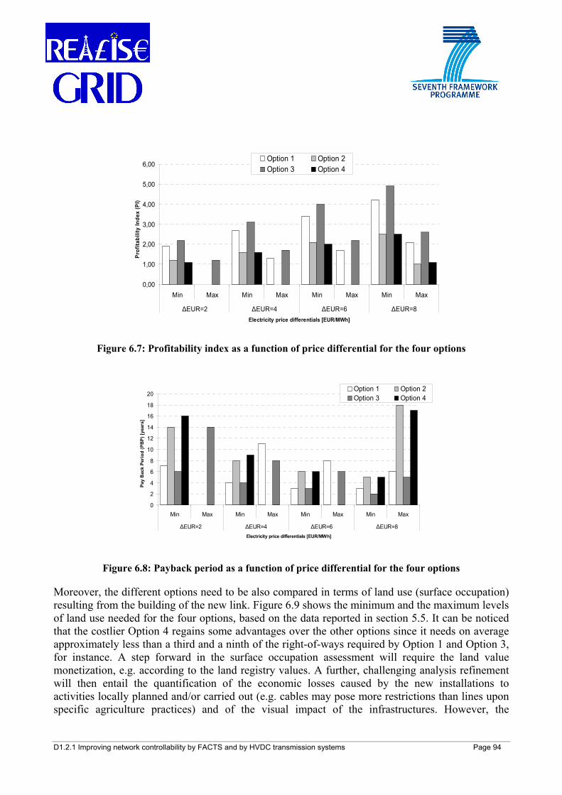
D1.2.1 Improving network controllability by FACTS and by HVDC transmission systems Page 94
0,00
1,00
2,00
3,00
4,00
5,00
6,00
Min Max Min Max Min Max Min Max
ΔEUR=2 ΔEUR=4 ΔEUR=6 ΔEUR=8Electricity price differentials [EUR/MWh]
Prof
itabi
lity
Inde
x (P
I)
Option 1 Option 2Option 3 Option 4
Figure 6.7: Profitability index as a function of price differential for the four options
0
2
4
6
8
10
12
14
16
18
20
Min Max Min Max Min Max Min Max
ΔEUR=2 ΔEUR=4 ΔEUR=6 ΔEUR=8Electricity price differentials [EUR/MWh]
Pay
Bac
k Pe
riod
(PB
P) [y
ears
]
Option 1 Option 2Option 3 Option 4
Figure 6.8: Payback period as a function of price differential for the four options
Moreover, the different options need to be also compared in terms of land use (surface occupation) resulting from the building of the new link. Figure 6.9 shows the minimum and the maximum levels of land use needed for the four options, based on the data reported in section 5.5. It can be noticed that the costlier Option 4 regains some advantages over the other options since it needs on average approximately less than a third and a ninth of the right-of-ways required by Option 1 and Option 3, for instance. A step forward in the surface occupation assessment will require the land value monetization, e.g. according to the land registry values. A further, challenging analysis refinement will then entail the quantification of the economic losses caused by the new installations to activities locally planned and/or carried out (e.g. cables may pose more restrictions than lines upon specific agriculture practices) and of the visual impact of the infrastructures. However, the
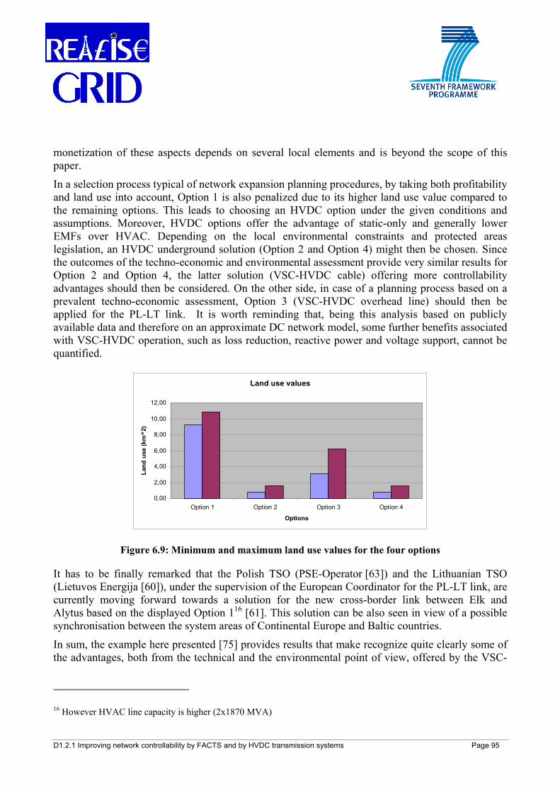
D1.2.1 Improving network controllability by FACTS and by HVDC transmission systems Page 95
monetization of these aspects depends on several local elements and is beyond the scope of this paper.
In a selection process typical of network expansion planning procedures, by taking both profitability and land use into account, Option 1 is also penalized due to its higher land use value compared to the remaining options. This leads to choosing an HVDC option under the given conditions and assumptions. Moreover, HVDC options offer the advantage of static-only and generally lower EMFs over HVAC. Depending on the local environmental constraints and protected areas legislation, an HVDC underground solution (Option 2 and Option 4) might then be chosen. Since the outcomes of the techno-economic and environmental assessment provide very similar results for Option 2 and Option 4, the latter solution (VSC-HVDC cable) offering more controllability advantages should then be considered. On the other side, in case of a planning process based on a prevalent techno-economic assessment, Option 3 (VSC-HVDC overhead line) should then be applied for the PL-LT link. It is worth reminding that, being this analysis based on publicly available data and therefore on an approximate DC network model, some further benefits associated with VSC-HVDC operation, such as loss reduction, reactive power and voltage support, cannot be quantified.
Land use values
0,00
2,00
4,00
6,00
8,00
10,00
12,00
Option 1 Option 2 Option 3 Option 4
Options
Land
use
(km
^2)
Figure 6.9: Minimum and maximum land use values for the four options
It has to be finally remarked that the Polish TSO (PSE-Operator [63]) and the Lithuanian TSO (Lietuvos Energija [60]), under the supervision of the European Coordinator for the PL-LT link, are currently moving forward towards a solution for the new cross-border link between Ełk and Alytus based on the displayed Option 116 [61]. This solution can be also seen in view of a possible synchronisation between the system areas of Continental Europe and Baltic countries.
In sum, the example here presented [75] provides results that make recognize quite clearly some of the advantages, both from the technical and the environmental point of view, offered by the VSC-
16 However HVAC line capacity is higher (2x1870 MVA)
D1.2.1 Improving network controllability by FACTS and by HVDC transmission systems Page 96
HVDC technology. In cases where environmental/social drivers justify the financing of underground solutions, the VSC-HVDC technology represents an attractive option to be taken into account for its flexibility and fast controllability features, in conjunction with HVDC cables.
6.3.4.2 Central Europe cases
A techno-economic assessment of the insertion of FACTS and HVDC to locally enhance the transmission capacity in the Continental European power system is here presented. This analysis is based on load flow implementation results, which have been then utilised for the calculation of the economic indicators (seen in section 6.3.1) needed for assessing and comparing transmission investments.
Reference system is the 400-220 kV European transmission grid. Attention has been paid especially to the regional power transmission system and cross-border ties of Central-East Europe (comprising the networks of Germany, Austria, Poland, Czech Rep., Slovakia, Hungary and Slovenia) [70]. In particular, focus is on the links of Czech Republic (CZ), Slovakia (SK), Austria (AT) and Hungary (HU), where more network corridors are very frequently congested [57][58]. Figure 6.10 depicts a schematic representation of this part of the test network with the respective cross-border capacity limits (as of 2007) [72]. A TRM of 200 MW has been considered for the examined cases. In the following, different cases of FACTS and HVDC applications have been considered: tests simulating the implementation of lossless UPFC and VSC-HVDC, opportunely modeled for DC load flow, have been carried out to compare these technologies with respect to different HVAC lines in the system.
In the base case (without FACTS and HVDC) DC load flow analysis on the test network points out bottlenecks at the CZ-AT and SK-HU borders. In the first case, in fact, the cross-border interconnection lines, Slavetice-Dürnrohr and the 2x220 kV Sokolnice-Bisamberg (see Figure 6.10), transport 635 MW and 250 MW, respectively, which result in a total 885 MW: this value corresponds to the TTC on the CZ-AT tie (since the (n-1) criterion is met). However, the difference between TTC and TRM exceeds the total secure power transit, the Net Transfer Capacity (NTC), set at 600 MW on the CZ-AT interface (2007 data). In the second case there is also a similar condition: the two cross-border lines, Levice-Göd and Gabcikovo-Györ (see Figure 6.10), carry power flows of 863 MW and 457 MW, respectively, for a total 1320 MW cross-border flow, while the total NTC on the SK-HU interface is set at 1100 MW (2007 data) [17]. In this condition, a FACTS device like the UPFC and a VSC-HVDC link have been considered [72][76] as they may increase the transferred power from CZ to AT and from SK to HU by relieving congestions and increasing the cross-border trade.
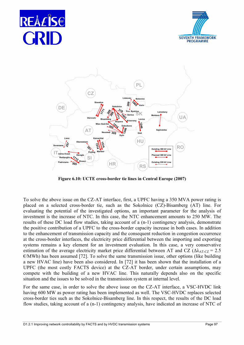
D1.2.1 Improving network controllability by FACTS and by HVDC transmission systems Page 97
SKSokolnice
KrizovanyStupava
Lienz
Soverzene
Nošovice
VarinSlavetice
Dürnrohr Bisamberg
Lemešany
Györ
Wien Süd-Ost
Kainachtal
Maribor
Levice
Göd
DivacaPadriciano
Redipuglia
Udine Ovest Okroglo
Sajóivánka
Moldava
Gabcikovo
257
26917
11
Obersielach
Podlog
351
1514
1514
Neusiedl
1514305
305 1246
1246
1712305
269
Liskovec
Pov. Bystrica
269
Senica
3181503
1711
1465DE
CZ
PL
UA
HU
AT
ITRO
HRSI
RS
Existing 380 kV Line
Planned 380 kV Line
Existing 220 kV Line
Figure 6.10: UCTE cross-border tie lines in Central Europe (2007)
To solve the above issue on the CZ-AT interface, first, a UPFC having a 350 MVA power rating is placed on a selected cross-border tie, such as the Sokolnice (CZ)-Bisamberg (AT) line. For evaluating the potential of the investigated options, an important parameter for the analysis of investment is the increase of NTC. In this case, the NTC enhancement amounts to 250 MW. The results of these DC load flow studies, taking account of a (n-1) contingency analysis, demonstrate the positive contribution of a UPFC to the cross-border capacity increase in both cases. In addition to the enhancement of transmission capacity and the consequent reduction in congestion occurrence at the cross-border interfaces, the electricity price differential between the importing and exporting systems remains a key element for an investment evaluation. In this case, a very conservative estimation of the average electricity market price differential between AT and CZ (ΔλAT-CZ = 2.5 €/MWh) has been assumed [72]. To solve the same transmission issue, other options (like building a new HVAC line) have been also considered. In [72] it has been shown that the installation of a UPFC (the most costly FACTS device) at the CZ-AT border, under certain assumptions, may compete with the building of a new HVAC line. This naturally depends also on the specific situation and the issues to be solved in the transmission system at internal level.
For the same case, in order to solve the above issue on the CZ-AT interface, a VSC-HVDC link having 600 MW as power rating has been implemented as well. The VSC-HVDC replaces selected cross-border ties such as the Sokolnice-Bisamberg line. In this respect, the results of the DC load flow studies, taking account of a (n-1) contingency analysis, have indicated an increase of NTC of
D1.2.1 Improving network controllability by FACTS and by HVDC transmission systems Page 98
250 MW (calculated according to the rules in [58]), proving the positive contribution of VSC-HVDC to the cross-border capacity increase on the interface CZ-AT.
In order to assess the investment in this VSC-HVDC option at CZ-AT interface, the economic indicators seen in section 6.3.1 have to be calculated. To do this, starting time reference is year 2010 with a timeframe of 25 years. It is assumed that the considered situation in terms of load and generation (connected to the transmission network) in the Central-East Europe system will be kept over the years of observation, while planned interconnections in the region (apart from the planned doubling of Slavetice (CZ)-Dürnrohr (AT) line) have been considered. The capital expenditure is considered to be 60 k€/MW for every VSC-HVDC converter (see also Table 5.2), adding 1% of the initial investment for annual maintenance. Two scenarios for the price differential ΔλAT-CZ have been analysed, assuming conservative values of 5 €/MWh (lower price differential scenario) and 7 €/MWh (higher price differential scenario). Considering an interest rate of 10%, it is possible to derive the results shown in Table 6.3.
ΔλAT-CZ NPV IRR PI PBP
5 €/MWh 16.3 M€ 13% 1.25 13 years 7 €/MWh 49 M€ 20% 1.74 7 years
Table 6.3: Economic results for VSC-HVDC on CZ-AT tie
These results [76] prove the techno-economic feasibility of an investment in VSC-HVDC replacing existing HVAC line(s), especially in presence of regions with a high electricity price differential.
The planned doubling of the existing 400 kV line from Slavetice (CZ) to Dürnrohr (AT) has been at the end put in place and solved for the time being the congestion at CZ-AT interface.
In the SK-HU case, the utilisation of a 350 MVA UPFC located on the line Gabcikovo-Györ leads to a NTC increase of 115 MW. This option has been compared with the new HVAC line from the substation of Moldava (SK) to the node of Sajóivánka (HU) (see Figure 6.10). This line has been already planned but still local problems hinder the project [71]. A FACTS device might be a feasible option to bypass these local issues and would require a much shorter lead time than that required for a new line. The analysis carried out in [72] has considered a timeframe of 20 years and a conservative estimation of the average electricity market price differential between HU and SK (ΔλHU-SK = 1.9 €/MWh). It has been also assumed that the situation in terms of load and generation (connected to the transmission network) and price differentials will be kept over the years of observation. The capital expenditure is considered to be 400 k€/km for a new 400 kV transmission line and 90 k€/MVA for a UPFC (see also Table 5.1 and Table 5.2), adding 1% of the initial investment for annual maintenance. Considering an interest rate of 10%, it has been shown in [72] that building the new line is more favourable than installing a UPFC: in this case a higher UPFC rating would be necessary to expand more largely the NTC and have a more feasible alternative. It has also to be remarked however that in this analysis several benefits associated with FACTS utilisation, such as loss reduction, voltage support, reactive power control, have not been addressed. Furthermore, the installation of FACTS devices can be more feasible where several constraints (socio-political, environmental, economic) hinder the extension of the transmission system, particularly in the short-mid term.
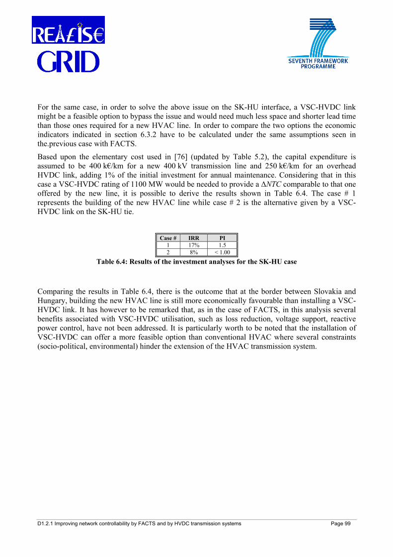
D1.2.1 Improving network controllability by FACTS and by HVDC transmission systems Page 99
For the same case, in order to solve the above issue on the SK-HU interface, a VSC-HVDC link might be a feasible option to bypass the issue and would need much less space and shorter lead time than those ones required for a new HVAC line. In order to compare the two options the economic indicators indicated in section 6.3.2 have to be calculated under the same assumptions seen in the.previous case with FACTS. Based upon the elementary cost used in [76] (updated by Table 5.2), the capital expenditure is assumed to be 400 k€/km for a new 400 kV transmission line and 250 k€/km for an overhead HVDC link, adding 1% of the initial investment for annual maintenance. Considering that in this case a VSC-HVDC rating of 1100 MW would be needed to provide a ΔNTC comparable to that one offered by the new line, it is possible to derive the results shown in Table 6.4. The case # 1 represents the building of the new HVAC line while case # 2 is the alternative given by a VSC-HVDC link on the SK-HU tie.
Case # IRR PI
1 17% 1.5 2 8% < 1.00
Table 6.4: Results of the investment analyses for the SK-HU case
Comparing the results in Table 6.4, there is the outcome that at the border between Slovakia and Hungary, building the new HVAC line is still more economically favourable than installing a VSC-HVDC link. It has however to be remarked that, as in the case of FACTS, in this analysis several benefits associated with VSC-HVDC utilisation, such as loss reduction, voltage support, reactive power control, have not been addressed. It is particularly worth to be noted that the installation of VSC-HVDC can offer a more feasible option than conventional HVAC where several constraints (socio-political, environmental) hinder the extension of the HVAC transmission system.
D1.2.1 Improving network controllability by FACTS and by HVDC transmission systems Page 100
7 CONCLUSIONS
The present report focuses on Flexible Alternating Current Transmission System (FACTS) and High Voltage Direct Current (HVDC) devices: these are innovative and promising power electronics-based technologies which can help transmission planners and operators addressing today’s grid management issues. The final goal is to achieve a modern, flexible, and robust European transmission system.
In the transmission planning process, the network expansion is pursued by transmission planners typically via the utilization of conventional High Voltage Alternating Current (HVAC) lines properly addressing the specific planning issue. Nowadays, due to different environmental constraints, this traditional approach is frequently no longer feasible, implying a higher socio-environmental cost with respect to the benefits possibly gained. This is related to environmental (e.g. public concern over the impact of electromagnetic fields on health, aesthetics of transmission equipment, land value detriment), economic (e.g. time-consuming construction of new lines, need for many years, in some cases, and for money), political (e.g. difficulty in obtaining new rights-of-way) obstacles to building new lines. To circumvent these problems, a number of non-standard technologies can be also deployed, among them FACTS and HVDC technologies. In fact, these devices offer the possibility to increase transmission network capacity and flexibility and generally enhance system reliability, security, and controllability with a limited environmental impact. These properties are especially important in a deregulated environment, where, in presence of more frequent and severe corridor congestions (especially at cross-border level in Europe), fast-reacting FACTS and HVDC elements can efficiently avoid or relieve network congestions. An effective way to cope with this situation consists in more efficiently utilizing the currently existing transmission structures. To this goal, it is necessary to free paths that are ‘occupied’ in undesired power transactions (i.e., loop flows and reactive-power transmission) in order to effectively utilize these lines and to prevent possible system congestion. This can then lead to a reduced need for building new HVAC lines with consequent environmental and economic benefits.
Furthermore, power flow patterns dictated by market decisions are more unpredictable and the uncertainties in generation and network planning are requiring transmission systems to be as flexible as possible. Moreover, the deployment of FACTS and HVDC can allow for a further, smoother integration of variable renewable energy sources (RES) power plants into the European power system. FACTS and HVDC devices are able to address all these needs making utility networks more reliable, more controllable, and more efficient.
FACTS devices are able to quickly control at least one of the parameters directly impacting on transmission line power flow (i.e., series impedance, nodal voltage amplitude, nodal voltage angular difference, line current, and shunt impedance). The utilization of FACTS devices can lead to the following important advantages related to the enhancement of transmission network control:
• control active and reactive power flows in a smooth, rapid way up to a certain level • reduce the undesired reactive-power flows in the system and therewith the network losses • increase the loading of transmission lines to levels nearer their thermal limits without
violating (n-1) security constraints
D1.2.1 Improving network controllability by FACTS and by HVDC transmission systems Page 101
• improve the steady-state and transient stability • reduce the series voltage drops (in amplitude and phase) on the lines • limit the voltage oscillations within the due range in presence of variation of transmission
power • enhance the system damping • control undesired loop flows • control voltage and improve power quality.
Furthermore, FACTS controllers, in comparison to mechanical devices – such as transformer tap changers, shunt capacitor switches etc. that have controlled the AC power system so far – are not subject to mechanical wear: this is a great advantage of FACTS devices in addition to their high flexibility and speed.
FACTS elements can be thyristor-controlled or voltage source-controlled. The voltage source-based devices are the most advanced ones of the FACTS family, offering the possibility for a smoother, faster control of active and/or reactive power flow and/or nodal voltage amplitude independently from the current. The most complete and versatile (and costly) FACTS device is the Unified Power Flow Controller (UPFC), able to independently and simultaneously control all the three parameters. The UPFC has been so far applied just in three installations worldwide (all outside Europe: two in the United States, one in South Korea), while the most widespread FACTS is the Static VAR Compensator (SVC), mostly suitable for voltage control and oscillation damping. In Europe there are several SVC installations, some of them also having the relocatability feature (such as in England): this aspect may play a role in the future as an additional benefit provided by these technologies. SVCs are thyristor-based FACTS, as well as the Thyristor Controlled Series Capacitor (TCSC), which can provide different benefits including dynamic stability and power flow control by regulating the series impedance. These devices are also more frequently used worldwide (recent applications are in Brazil, China, and India), whereas in Europe only one installation has been recorded in Sweden. Another promising and already deployed FACTS is the Static Synchronous Compensator (STATCOM), which can provide a fast control of voltage and reactive power and can therefore be very useful for wind power plants integration.
The drawbacks of the FACTS technology so far are represented by its complexity and, mostly, by its costs, which are higher than those ones of mechanical devices. This factor has slowed a more widespread insertion of FACTS devices in transmission systems. However, since all FACTS controllers are applications of similar technology, their deployment can benefit from economies of scale linked with volume production. The cost of these devices is decreasing as development of high-power electronics and with potential increased savings due to economy of scale.
Capital expenditures for transmission equipment are highly dependent on different parameters such as the power rating, the operating voltage, the local environmental/geographical characteristics and material/manpower costs. In general, environmental constraints increase costs and implementation time for overhead lines (OHL), whilst technological advances significantly reduce costs of power electronics components. It has also to be stressed that to-date the FACTS projects already implemented deploying voltage source-based technologies (like STATCOM and UPFC) are still too
D1.2.1 Improving network controllability by FACTS and by HVDC transmission systems Page 102
few worldwide to make a comparable cost detail analysis. In economic terms, the installation of FACTS devices can be used to have the following direct advantages:
• additional power trading due to increased transmission capability, • avoidance/postponement of investments in new high-voltage transmission lines and/or in
new power generation, • system reliability increase, • system losses reduction.
From the environmental point of view, FACTS devices have also an impact in terms of increased surface occupation in the substations (for instance, for an UPFC, this increase would range from 4000 to 5000 m2). Some other aspects need or can also be evaluated, such as the potential increased noise, or the electromagnetic interference (EMI) emissions. In terms of the materials used, FACTS devices do not use hazardous materials, as they are based on the semiconductors technology, i.e. on the same element (silicon) that is the second most abundant element on the earth crust and the major constituent of most sand in the planet.
As a mature technology with more than 50 years of application, HVDC has been proven to be a reliable and valuable transmission technology. It exhibits characteristics that have already made it widely attractive over HVAC transmission for specific applications, such as long distance power transmission, long submarine cable links and interconnection of asynchronous systems. Currently, recent advances in power electronics, coupled with traditional features of HVDC, may bring to further deploying this technology with the aim of improving operation and supporting the development of onshore and, possibly, offshore European transmission grids. This is the case of the promising self-commutating Voltage Source Converter (VSC)-based HVDC, which represents the state-of-the-art technology for connection of offshore wind farms via HVDC cables and also for multi-terminal applications. Crucial advantages of VSC-HVDC compared to the line-commutated Current Source Converter (CSC)-based HVDC (the classic HVDC) are that it gives the possibility to feed reactive power into a network node and provide a smoother voltage support. This positively impacts on the operation, controllability, and stability of the power grid.
CSC-HVDC is best suited for the transmission of bulk power over long distances. The aim is to provide additional transmission capacity for the large-scale cross-border power trade, or for the transmission of wind power from countries with high wind generation and low load to power importing countries. It is mostly used in the European power system as a feasible solution for the interconnection of power system zones within the pan-European ENTSO-E power grid and for longer undersea cable interconnections. Another potential application of CSC-HVDC is the reinforcement of the B2B (back-to-back) couplings between the still asynchronously operated power grids of ENTSO-E where additional transmission capacity is desirable for further promoting the cross-border power trade.
VSC-HVDC is useful for the interconnection of remote offshore wind farms to the main power grid since VSC-HVDC is not depending on a specified ESCR or on reactive power support at the connection points in order to perform a reliable commutation process. Furthermore, this independency of reactive power support enables VSC-HVDC to perform a black start which helps
D1.2.1 Improving network controllability by FACTS and by HVDC transmission systems Page 103
TSOs to re-energize network sections that suffered from a system blackout. VSC-HVDC can provide additional capacity for the point-to-point power transmission over short- to medium-long distances within a power grid while also providing reactive power support at its terminals. This contributes to power system stability and frees up transmission capacity on neighbouring lines that was formerly occupied by reactive power transmission. In combination with a wide-area monitoring system, the fast modulation of power injection at the HVDC terminals can be used to damp power oscillations within the power grid and to assure system stability.
Although the additional investment costs of a VSC-HVDC converter station are higher than those ones of an AC substation, the investment costs of the overall DC transmission system can be lower than those ones of the AC transmission system: the cost savings of the transmission line can make up for the higher station costs of the VSC station if a certain transmission distance is reached. VSC-based HVDC systems can be a better economic option compared to HVAC systems or to the installation of a local generation source if the transmission distance is large enough.
The environmental fitting of an electrical power transmission system is of increasing importance. In this context, the clear environmental advantage of HVDC transmission is its ability to go underground by the use of HVDC cables. The use of cables minimizes the visual impact of the transmission line since the surface area over the cable run can be renaturalized with e.g. bushes or shallow root trees, as long as the cable can be made accessible for maintenance or repair purposes at short notice. In case of overhead lines, the width of right-of-way can be reduced by approximately 30-50 % when choosing HVDC instead of HVAC transmission. Furthermore, the electromagnetic field emission of HVDC lines is not pulsating and can be forced to minimum values when a dedicated return conductor is used and the conductor arrangement is selected accordingly. The result is a significantly lower electromagnetic pollution compared to the electromagnetic emissions by conventional HVAC transmission, especially when overhead lines are used. However, it shall be stated clearly that today all HVAC overhead and cable lines comply with all requirements in terms of electromagnetic compatibility. It is expected that the public acceptance of electrical power transmission is improved by the use HVDC instead of HVAC transmission systems due to its smaller environmental impact.
The planned France-Spain interconnection line is a clear example where the implementation of an HVDC interconnection is chosen as a technically and environmentally feasible solution. The aim is to address cross-border congestions (frequently occurring in both directions), enhancing the net transfer capacity and avoiding overloading of the transmission line, with a clear environmental advantage over conventional HVAC transmission. The exploitation of HVDC features is also expected by the further deployment of this technology for the planned France-Italy interconnection line as well as for the VSC-HVDC link under construction in southern Sweden (South-West project).
Considering the main features and abilities of FACTS and HVDC, the present report introduces also planning process guidelines to be applied for general and some specific application cases. There are two possible ways to include FACTS and HVDC in the current transmission planning practice, as carried out by network planners: by a bottom-up approach and by a top-down approach. The bottom-up approach focuses firstly on the advantages and disadvantages of FACTS and HVDC
D1.2.1 Improving network controllability by FACTS and by HVDC transmission systems Page 104
transmission systems, the effects they can have on power system operation and the aspects that need to be taken into account during the planning stage of a network expansion process. The top-down approach focuses firstly on a transmission issue, and then on the possible different conventional and advanced solutions, and on the criteria that need to be followed to make a ranking of alternative options.
Three typical issues that European transmission network planners may be frequently confronted with in the future are addressed: the need to increase transmission capacity within a section of the power grid, the coupling of asynchronously operated networks, and the connection of offshore-located wind parks to the main grid.
Schematic flow diagrams, which can offer a support to basically select a list of possible technical solutions to one of the above stated issues (namely, the need to increase transmission capacity), are also presented. The provided list of possible technical solutions needs to be then further proved by network studies taking into account the actual grid configuration; in this frame, the different technological, economic and environmental criteria to address each specific problem have to be considered.
These guidelines provide general schemes and measures, displaying the potential role of FACTS and HVDC while including these advanced technologies among the possible reinforcement options of the transmission expansion planning process.
Some practical examples of potential applications of FACTS and HVDC in the European power system are also reported.
Also, it has to be noted that in a highly meshed network, as the European one, if HVDC and FACTS become extensively deployed, they will deliver real benefits only when subjected to a coordinated and hierarchical control; this in turn requires a wide-area, real-time information gathering and analysis system. Software and Information and Communication Technology (ICT) can contribute as well to increase the adequacy and robustness of the system - thus reducing the need for building new infrastructures - and to augment its observability and governability: these aspects will be treated in REALISEGRID Deliverable D1.2.2.
The final goal is to provide the European TSOs with the key elements and guidelines to support their decision-making process, allowing the inclusion of FACTS and HVDC among the possible reinforcement options of modern transmission expansion planning processes.
D1.2.1 Improving network controllability by FACTS and by HVDC transmission systems Page 105
8 REFERENCES
[1] N.G. Hingorani, High Power Electronics and Flexible AC Transmission System, IEEE Power Engineering Review, Jul. 1988, pp. 3-4.
[2] N.G. Hingorani, L. Gyugyi, Understanding FACTS: Concepts and Technology of Flexible AC Transmission Systems, IEEE Press Inc., 2000.
[3] A.A. Edris, Proposed Terms and Definitions for Flexible AC Transmission Systems (FACTS), IEEE Trans. on Power Delivery, Vol. 12, No. 4, Oct. 1997.
[4] Cigré TF 38-01-06, Load Flow Control in High Voltage Power Systems using FACTS Controllers, Jan. 1996.
[5] X.P. Zhang, C. Rehtanz, B. Pal, Flexible AC Transmission Systems: Modeling and Control, Springer, 2006.
[6] Y.H. Song, A.T. Johns, Flexible AC Transmission Systems (FACTS), IEE Power and Energy Series, 1999.
[7] IEEE PES, FACTS Applications, 1996. [8] IEEE / Cigré FACTS WG, FACTS Overview, 1995. [9] D. Young, Hitting a Moving Target with Relocatables SVCs, IEE Colloquium on FACTS,
London (UK), Nov. 23, 1998. [10] ABB Ltd. Corporation website, http://www.abb.com [11] Siemens Ltd. Corporation website, http://www.siemens.com [12] R.A. Ahangar, A. Sheykholeslami, H. Ghaffari, Power Flow Modelling for Power Systems
with Dynamic Flow Controller, Elektrika, Malaysia, Vol. 10, No. 2, 2008, pp. 22-27. [13] New York Power Authority website, http://www.nypa.gov [14] ABB Ltd., It's time to connect, Information brochure on HVDC Light, 2008. [15] M. Bahrman, HVDC Transmission Overview, IEEE/PES Transmission and Distribution
Conference and Exposition 2008, Chicago (USA), Apr. 20-23, 2008, pp. 1-7. [16] A. Gustafsson, HVDC Cable Systems - State of the Art and Development, Joint AEE/ Cigré
Workshop on HVDC Transmission - Technology State of the Art and Practical Experiences, Rome (Italy), Nov. 27, 2008
[17] R. Rudervall, J.P. Charpentier, R. Sharma, High Voltage Direct Current (HVDC) Transmission Systems Technology Review Paper, Energy Week, 2000.
[18] A. Orzechowski, Analysis of possible enhancement of transmission capacity while converting 220 kV alternating current overhead lines into direct current lines, paper B4-105, Cigré Session 2004.
[19] D.A. Woodford, HVDC Transmission, Manitoba HVDC Research Center, 1998. [20] B.R. Andersen, HVDC Transmission Opportunities and Challenges, 8th IEE International
Conference on AC and DC Power Transmission, London (UK), Mar. 28-31, 2006, pp. 24-29.
[21] Cigré WG B4.39, Integration of Large Scale Wind Generation using HVDC and Power Electronics, Feb. 2009.
[22] Cigré B4.04/A2-1 Joint Task Force, Analysis of HVDC Thyristor Converter Transformer Performance, 2004.
[23] Cigré WG 14.05, Commutation Failures - Causes and Consequences, 1995.
D1.2.1 Improving network controllability by FACTS and by HVDC transmission systems Page 106
[24] K. von Sengbusch, J. Hanson, Einbindung von HGÜ-Systemen in Wechselstromnetze - Erfahrungen und Potentiale, Internationaler ETG-Kongreß, 2007 (in German).
[25] K. Habur, D. O'Leary, FACTS - Flexible Alternating Current Transmission Systems for Cost Effective and Reliable Transmission of Electrical Energy, Siemens - World Bank document.
[26] CESI, IIT, ME, RAMBØLL A/S, TEN-ENERGY-Invest, Summary Report, 2005. [27] ICF Consulting, Unit Costs of Constructing New Transmission Assets at 380kV within the
European Union, Norway and Switzerland, 2002. [28] European Commission, DG Energy and Transport, Trans-European Energy Networks
(TEN-E) website, Priority project of European interest EL.3, 2007. [29] B. Cova, M. de Nigris, Non-conventional Solutions for Reinforcing Connections among
Power Systems: The Example of the New France-Spain Cross-Border Line. Joint AEE/ Cigré Workshop on HVDC Transmission - Technology State of the Art and Practical Experiences, Rome (Italy), Nov. 27, 2008.
[30] Statnett, TenneT, HVDC Transmission and Lifetime Expectancy. [31] G. Xiaojiang, B. Guangquan, T.Yang, M. Shiying, Supplementary Control for SVC to
Improve the Converter Commutation Performance of HVDC, Joint International Conference of POWERCON2008 and IEEE Power India Conference, New Delhi (India), Oct. 12-15, 2008.
[32] R.W. De Doncker, C. Meyer, R. Lenke, F. Mura, Power Electronics for Future Utility Applications, 7th International Conference on Power Electronics and Drive Systems, Bangkok (Thailand), Nov. 27-30, 2007.
[33] R.W. de Doncker, C. Meyer, M. Kowal, Circuit Breaker Concepts for Future High-Power DC-Applications, IEEE Industry Applications Conference 2005, Hong Kong (China), Oct. 2-6, 2005, Vol. 2, pp. 860-866.
[34] P.M. McEwan, S.B. Tennakoon, A Two-Stage DC Thyristor Circuit Breaker, IEEE Trans. on Power Electronics, Vol. 12, 1997, pp. 597-607.
[35] D. Jovcic, Thyristor-based HVDC with Forced Commutation, IEEE Trans. on Power Delivery, Vol. 22, 2007, pp. 557-564.
[36] R. Piovan, L. Zanotto, T. Bonicelli, Vacuum Breaker for High DC Current: Experimental Performances and Operational Limits, IEEE Trans. on Plasma Science, Vol. 37, No. 1, 2009, pp. 229-235.
[37] L. Tang, B.T. Ooi, Protection of VSC-Multi-Terminal HVDC against DC Faults, IEEE Power Electronics Specialists Conference, Cairns (Australia), Jun. 23-27, 2002, Vol. 2, pp. 719-724.
[38] Y.Z. Sun, L. Peng, F. Ma, G.J. Li, P.F. Lv, Design a Fuzzy Controller to Minimize the Effect of HVDC Commutation Failure on Power System, IEEE Trans. on Power Systems, Vol. 23, 2008, pp. 100-107.
[39] F. Schettler, H. Huang, N. Christl, HVDC Transmission Systems using Voltage Source Converter Design and Applications, IEEE PES Summer Meeting, Seattle (USA), Jul. 16-20, 2000.
[40] C. Zhou, Z. Xu, Study on Commutation Failure of Multi-Infeed HVDC System, PowerCon - International Conference on Power System Technology, Kunming (China), Oct. 13-17, 2002.
D1.2.1 Improving network controllability by FACTS and by HVDC transmission systems Page 107
[41] Z. Xu, B. Zhang, S. Sirisukprasert, X. Zhou, A.Q. Huang, The Emitter Turn-Off Thyristor-Based DC Circuit Breaker, Proc. of IEEE-PES Winter Meeting, New York (USA), Jan. 27-31, 2002.
[42] Siemens AG, SVC Availability, 2009. [43] L.J. Cai, I. Erlich, Optimal choice and allocation of FACTS devices in deregulated
electricity market using genetic algorithms, Proc. of IEEE-PES General Meeting, Denver (USA), Jun. 6-12, 2004.
[44] CESI, Analisi e valutazione dell'impatto in rete conseguente all'inserimento dei dispositivi FACTS, Jun. 2000 (in Italian).
[45] D. Klinect, D. Nichols, S. Sebo, L. Xu, X. Liu, B. Cramer, M. Silva, R. Olsen, J. Ramie, Electromagnetic noise emission measurements near the Flexible AC Transmission System (FACTS) device at the Sullivan (TVA) station, Proc. of 2005 IEEE PowerTech Conference, St. Petersburg (Russia), Jun. 27-30, 2005.
[46] M. Matele, Enhancing of transmission capability of power corridors by means of series compensation, PowerTech Conference, Mumbai (India), Oct. 1999.
[47] EPRI, Flexible AC Transmission Systems (FACTS): Hardware Feasibility Study of a Minnesota Power 150-MVA, 115-kV Thyristor Controlled Phase Angle Regulating Transformer (TCPAR), Report TR-103904, Jun. 1994.
[48] Cigré JWG 14/37/38/39-24, FACTS Technology for Open Access, Aug. 2000. [49] EPRI, Guide for Economic Evaluation of Flexible AC Transmission Systems (FACTS) in
Open Access Environments, Report TR-108500, Aug. 1997. [50] European Parliament and Council, Decision No. 1364/2006/EC of the European Parliament
and of the Council of 6 September 2006 laying down guidelines for trans-European energy networks and repealing Decision 96/391/EC and Decision No. 1229/2003/EC, Brussels (Belgium), Sep. 6, 2006.
[51] European Commission, Communication from the Commission to the European Parliament, the Council, the European Economic and Social Committee and the Committee of the Regions, 20 20 by 2020 - Europe's climate change opportunity, COM(2008) 30 final, Brussels (Belgium), Jan. 23, 2008.
[52] European Commission, Communication from the Commission to the European Parliament, the Council, the European Economic and Social Committee and the Committee of the Regions, Investing in the Development of Low Carbon Technologies (SET-Plan), COM(2009) 519 final, Brussels (Belgium), Oct. 7, 2009.
[53] SmartGrids – European Technology Platform for the Electricity Networks of the Future website, http://www.smartgrids.eu/
[54] European Technology Platform SmartGrids, Strategic Deployment Document (SDD) for Europe’s Electricity Networks of the Future [Online]. Available: http://www.smartgrids.eu/
[55] C. Podewils, Eine Rennstrecke für Ökostrom, Photon, Vol. 7, pp. 70-75, Jul. 2007 (in German).
[56] Q. Zhou, J.W. Bialek, Approximate Model of European Interconnected System as a Benchmark System to Study Effects of Cross-Border Trades, IEEE Trans. on Power Systems, Vol. 20, No. 2, May 2005, pp. 782-788.
[57] UCTE (Union for the Coordination of Transmission of Electricity) website http://www.ucte.org/ (now: http://www.entsoe.eu)
D1.2.1 Improving network controllability by FACTS and by HVDC transmission systems Page 108
[58] ETSO (European Transmission System Operators) website http://www.etso-net.org (now: http://www.entsoe.eu)
[59] BALTSO (Association of Baltic TSOs) website http://www.baltso.eu/ (now: http://www.entsoe.eu)
[60] Lietuvos Energija (LE) AB website http://www.lpc.lt/ [61] European Commission, DG Energy and Transport, Trans-European Energy Networks
(TEN-E) website, Priority project of European interest EL.7, 2008 [Online]. Available: http://ec.europa.eu/ten/energy/coordinators/doc/annual/3_mielczarski_en.pdf
[62] BALTREL (Baltic Ring Electricity Co-operation Committee) website http://www.baltrel.org/
[63] PSE-Operator website http://www.pse-operator.pl/ [64] KEMA Consulting, Analysis of the network capacities and possible congestion of the
electricity transmission networks within the accession countries, Jun. 2005 [Online]. Available: http://ec.europa.eu/energy/electricity/publications/doc/kema_accession_countries_final_june_2005.pdf
[65] IPA Energy Consulting, SwedPower, SEK Advisory Services, Lithuania-Poland High Voltage Transmission Inter-Connector Project, Jan. 2003.
[66] ETSO, Procedures for cross-border transmission capacity assessments, Oct. 2001 [Online]. Available: http://www.etso-net.org (now: http://www.entsoe.eu)
[67] N. Barberis Negra, J. Todorovic, T. Ackermann, Loss evaluation of HVAC and HVDC transmission solutions for large offshore wind farms, Electric Power Systems Research, Vol. 76, 2006, pp. 916-927.
[68] POWER (Perspectives of Offshore Wind Energy development in marine areas of Lithuania, Poland and Russia) project website, http://www.corpi.ku.lt/power/
[69] European Commission, Report on progress in creating the internal gas and electricity market, COM(2005)568, Brussels (Belgium), Nov. 2005 [Online]. Available: http://ec.europa.eu/energy/electricity/report_2005/doc/2005_report_en.pdf
[70] ERGEG, Electricity Regional Initiative, Central East Europe Region [Online]. Available: http://www.ergeg.org/portal/page/portal/ERGEG_HOME/ERGEG_RI/ERI/Central-East
[71] European Commission, Energy Package, Priority Interconnection Plan, COM(2006)846, Brussels (Belgium), Jan. 2007 [Online]. Available: http://eur-lex.europa.eu/LexUriServ/site/en/com/2006/com2006_0846en01.pdf
[72] A. L'Abbate, G. Fulli, E. Handschin, Economics of FACTS integration into the liberalised European power system, Proc. of 2007 IEEE PowerTech Conference, Lausanne (Switzerland), Jul. 1-5, 2007.
[73] Cigré WG 14.11, Guide for Upgrading Transmission Systems with HVDC Transmission, Aug. 1998.
[74] Cigré WG B4.37, VSC Transmission, Apr. 2005. [75] A. L’Abbate, G. Fulli, Sustainability analysis of VSC-HVDC in the liberalised European
power system: a practical case, Proc. of 2009 IEEE PowerTech Conference, Bucharest (Romania), Jun. 28 – Jul. 2, 2009.
D1.2.1 Improving network controllability by FACTS and by HVDC transmission systems Page 109
[76] A. L’Abbate, G. Fulli, Targeted HVDC Deployment for a Sustainable European Transmission System Development, Proc. of Power Systems Computation Conference (PSCC) 2008, Glasgow (UK), Jul. 14-18, 2008.
[77] Cigré WG B4.40, Static Synchronous Series Compensator (SSSC), Feb. 2009. [78] A. L’Abbate, Modeling of FACTS Devices and Applications in Liberalized Power Systems,
Doctoral degree dissertation, Politecnico di Bari (Italy)/Universität Dortmund (Germany), Sep. 2003/Feb. 2004.
[79] Cigré WG 14.18, Thyristor Controlled Series Compensation, Dec. 1997. [80] D. Divan, Improving power line utilization and performance with D-FACTS devices, Proc.
of IEEE – PES General Meeting, San Francisco (USA), Jun. 12-16, 2005. [81] N. Mithulananthan, A. Sode-yome, N. Acharya, Application of FACTS Controllers in
Thailand Power Systems, AIT Thailand, Jan. 2005. [82] Areva T&D website, http://www.arevatd.com [83] ENTSO-E, Research and Development Plan - Eurogrid 2020, Jan. 2010,
http://www.entsoe.eu [84] B.A. Renz, A.J.F. Keri, A.S. Mehraban, J.P. Kessinger, C.D. Schauder, L. Gyugyi, L.J.
Kovalsky, A.A. Edris, World’s First Unified Power Flow Controller on the AEP System, paper 14-107, Cigré Session, 1998.
[85] B.H. Chang, S.Y. Kim, J.S. Yoon, S.P. Moon, D.H. Baek, B.M. Kwak, J.B. Choo, Control Strategies Study for KEPCO UPFC Operation Automation in Korean Sub-Transmission System, paper B4-306, Cigré Session, 2006
[86] B. Fardanesh, M. Henderson, B. Shperling, S. Zelingher, L. Gyugyi, C. Schauder, B. Lam, J. Mountford, R. Adapa, A. Edris, Convertible Static Compensator Application to the New York Transmission System, paper 14-103, Cigré Session, 1998.
[87] A. Vaféas, S. Galant, T. Pagano, List of promising innovative grid technologies, REALISEGRID Deliverable D1.4.1, Feb. 2010, http://realisegrid.erse-web.it
[88] E. Zaccone, Synthetic description of performances and benefits of undergrounding transmission, REALISEGRID Deliverable D1.1.1, Dec. 2009, http://realisegrid.erse-web.it
[89] Nokian Capacitors, The largest Utility SVC supply by AREVA T&D Ltd., NC News, 2009. [90] ENTSO-E, Ten-Year Network Development Plan 2010-2020, Mar. 2010,
http://www.entsoe.eu [91] Cigré WG 14.20, Economic Assessment of HVDC Links, Jun. 2001. [92] G. Fulli, A.R. Ciupuliga, A. L’Abbate, M. Gibescu, Review of existing methods for
transmission planning and for grid connection of wind power plants, REALISEGRID Deliverable D3.1.1, Jun. 2009, http://realisegrid.erse-web.it
[93] A. L’Abbate, I. Losa, G. Migliavacca, A.R. Ciupuliga, M. Gibescu, H. Auer, K. Zach, Possible criteria to assess technical-economic and strategic benefits of specific transmission projects, REALISEGRID Deliverable D3.3.1, 2010, http://realisegrid.erse-web.it