Embed Size (px)
Citation preview

Revision Description: Date:
Approved for Use 23rd April 2007
Author: Reviewer: Approved: Jeff Bell Anne Potter Mike Willmore
Engineering Consultant Head of Stations Engineering Operations Engineering Director
Approved
Client: Originator:
Glasshouse 26-28 Glasshouse Yard London EC1A 4JU
+44 (0)20 7017 9000
Location: Project:
Engineering All Station projects
Title:
Project Engineer’s Handbook
Format: Document Number: Revision
A4 GNT-ENG-TM00-0554603 :01
The original master of this document is retained on the Document Management and Collaboration Database. Copies produced from the master, by whatever means, are deemed uncontrolled.
You must confirm that you hold the latest version, before using this document for its intended purpose.
Project Engineer’s Handbook Date: 23 April 2007 Doc No: GNT-ENG-TM00-0554603 Page: 2 of 80
Project Engineer’s Handbook Contents 1.0 Introduction................................................................................................................................................... 5 2.0 Organisation ................................................................................................................................................. 6 3.0 Project Team & Assurance Key Roles ......................................................................................................... 7 4.0 Project Engineer Role & Responsibility Overview...................................................................................... 10 5.0 Key Assurance Documents ....................................................................................................................... 12 5.1 Documents to be produced by the Project Engineer..................................................................... 15 6.0 Generic Project Lifecycle Model- Project Engineers Responsibilities........................................................ 17 7.0 Station Alliance Engineering Reviews........................................................................................................ 24 8.0 Assurance and other key Documents Production/Sign Off Schedule........................................................ 26 9.0 Standard Filing Systems ............................................................................................................................ 27 9.1 Engineering Operations Electronic Filing ...................................................................................... 27 9.2 PE Station File ............................................................................................................................... 27 10.0 Key Engineering Assurance Document Tracker ...................................................................................... 28 11.0 Individual Discipline Support Information ................................................................................................. 29 11.1 Fire Engineering .......................................................................................................................... 29 11.2 Electrical Services ....................................................................................................................... 33 11.3 Human Factors ............................................................................................................................ 36 11.4 Civil/Structural Engineering ......................................................................................................... 40 11.5 Mechanical Services.................................................................................................................... 43 11.6 Building Control Process ............................................................................................................. 45 11.7 Station Communication Systems................................................................................................. 46 11.8 Premises...................................................................................................................................... 51 Appendix A – Reference Documents/Standards/Procedures .......................................................................... 61 Appendix B – Project Engineer Check Sheets Templates ............................................................................... 65 B1 – PGR Check Sheets ..................................................................................................................... 66 B2 – Generic Site Inspection Check Sheets ....................................................................................... 72 B3 – BIU Cat 3 Assets......................................................................................................................... 74 B4 – Engineering Completion Declaration .......................................................................................... 76 Appendix C – Delivery into Service Flowchart ................................................................................................. 79

Project Engineer’s Handbook Date: 23 April 2007 Doc No: GNT-ENG-TM00-0554603 Page: 3 of 80
List of Abbreviations ACE: Alliance Chief Engineer ACHL: Asset Commissioning Handover Log AE: Metronet Rail Asset Engineer AFC: Approved for Construction AIP : Approval in Principle ALARP: As Low as Reasonably Practicable APM: Assistant Project Manager BCG: Building Control Group BiU: Consent to Bring into Use CDS: Conceptual Design Statement CM: Construction Manager DM: Design Manager DT: Design Team DTL: Design Team Leader EAD: Engineering Assurance Documents EAM: Engineering Assurance Manager EAT: Engineering Assurance Team ECD: Engineering Completion Declaration EM: Engineering Manager EMC: Electromagnetic Compatibility FSU: Fire Safety Unit HFIP: Human Factors Integration Plan HSE: Health and Safety Executive ITCHBU: Inspection, Test Commissioning and Bringing into Use Plan ITP: Inspection and Test Plan L & E: Lifts and Escalators LFEPA: London Fire and Emergency Planning Authority LU: London Underground LUCED: London Underground Chief Engineer’s Directorate LUCPO: London Underground Chief Programme Office LUL: London Underground Ltd MAP: Metronet Asset Performance MSAT: Metronet Space Application Team NCR: Non Compliance Report NOWRI: Notification of Works Requiring Inspection PAE: Project Assurance Engineer PAP: Project Assurance Plan PD: Project Director PDM: Project Development Manager PE: Project Engineer PGR: Project Governance Review PM: Project Manager PS: Planning Supervisor’s Representative RS: Requirements Schedule SDC: Site Design Coordinator SRCC: Safety Review and Change Control TE: Metronet Track Engineer TQ: Technical Query

Project Engineer’s Handbook Date: 23 April 2007 Doc No: GNT-ENG-TM00-0554603 Page: 4 of 80
WPE-A: Works, Plant and Equipment Applicability WPP: Works Package Plan

Project Engineer’s Handbook Date: 23 April 2007 Doc No: GNT-ENG-TM00-0554603 Page: 5 of 80
1.0 Introduction The purpose of this document is to provide guidance on the role of the Project Engineer within the Stations Alliance Engineering Director’s Organisation. It describes in detail the Project Engineer’s technical accountability and the way in which technical assurance is provided throughout the lifecycle of the Project.

Project Engineer’s Handbook Date: 23 April 2007 Doc No: GNT-ENG-TM00-0554603 Page: 6 of 80

Project Engineer’s Handbook Date: 23 April 2007 Doc No: GNT-ENG-TM00-0554603 Page: 7 of 80
3.0 Project Team and Key Responsibilities
• Alliance Engineering Director o Role to assure engineering governance of the Alliance Engineering System (people
and processes) and to ensure that engineering risks are managed within an effective framework that drives improvements in integrity, safety and profitability for the Alliance as a whole.
• Project Manager
o Responsible to the Stations Alliance Area Director for planning, controlling and implementing the multidiscipline project in order to deliver the works in accordance with the agreed workscope, meet the requirements for safety, quality and value for money, and meet the requirements for cost and timescale.
• Engineering Manager
o Responsible to the Stations Alliance Area Director for ensuring an appropriate engineering solution is provided for all the projects within their portfolio and that the solution meets the stated requirements and accepted standards. Accountable for ensuring that the Engineering Assurance regime is followed on all projects within his portfolio, including assurance submissions which must meet the required standards and be approved by the appropriate accredited authority.
• Lead Project Engineer
o Responsible to the Engineering Manager and Project Director for a single large complex project or a group of projects to ensure that appropriate engineering solution is provided for all the projects within their portfolio and that the solution meets the stated requirements and accepted standards. Accountable for ensuring that the Engineering Assurance regime is followed on all projects within his portfolio, including assurance submissions which must meet the required standards and be approved by the appropriate accredited authority. Responsible for mentoring of Project Engineers for projects allocated to them.
• Project Engineer
o Responsible to the Project Manager for ensuring the engineering solutions for their projects meet the stated requirements and accepted standards. Accountable for ensuring that the Engineering Assurance regime is followed on their projects, including assurance submissions which must meet the required standards and be approved by the appropriate engineering authority.
• Head of Stations Engineering Authority.
o Delegated responsibility for exercising Engineering governance in respect of Metronet Alliance works on behalf of Metronet SVP Engineering & Safety. Management of Chief Engineers/Architect Team. Responsible for the engineering input into the development of the Requirement Schedule 1 coordinating technical input from Metronet’s Planning and Asset Performance Teams as necessary.

Project Engineer’s Handbook Date: 23 April 2007 Doc No: GNT-ENG-TM00-0554603 Page: 8 of 80
• Alliance Chief Engineers - (Systems Integration, Civils/Structures, Communications,
Electrical, Mechanical, Fire, Premises, L&E, Power, Architect) o Accountable to the Head of Stations Engineering Authority for the technical content of
the Alliance Works for each of the individual disciplines and responsible for developing the RS1s in respect of the discipline and coordinating input from Metronet’s Planning and Maintenance Teams. Support of concession requests and promoting standard’s challenge.
• Head of Stations Engineering Operations
o Responsible for the performance and effectiveness of the Engineering Managers and their teams within the individual Area Director groups. Also responsible for liaison with the Metronet Alliance Chief Engineers, to obtain engineering approval and provide engineering input into Project Value Management as appropriate.
• Head of Engineering Production and Standards
o Acts as the single point of contact regarding standards between the Alliance and Metronet and facilitates queries to standards and requests for concessions.
• Head of Engineering Capability
o Role is to identify, direct, drive, improve and embed engineering capabilities within the engineering organisation. Also to identify and secure business benefits with respect to engineering and its delivery.
• Engineering Assurance Manager
o Responsible for the management of assurance submissions received from the Project Team including initial review of the submissions, gaining acceptance from the relevant Assurance Authority, presenting the submission to LU and dealing, with the assistance of the Project Team, any queries which may arise. Responsible for ad hoc training of Project Engineers to improve and standardise the quality of technical assurance submissions.
• Area Design Manager
o Responsible for leading the area design team, ensuring that the area station design programme is delivered within time and budget targets and to ensure the design meets the specified requirements. Responsible for ensuring that area construction teams receive adequate technical support from area design team.
• Metronet Asset Engineers – Asset Groups as Alliance Chief Engineers
o Responsible for confirming, on behalf of Metronet, the health of assets within their asset group and for ensuring that both self Assured Delivery Activities and the resulting condition of the assets meet the relevant standards.
• Metronet Asset Performance Project Interface Managers
o To provide a single point of contact with the Project in order to facilitate the integration of the Asset Management Plan with all Capital Project Delivery and ensure a smooth acceptance of new assets into the maintenance portfolio and operational service.

Project Engineer’s Handbook Date: 23 April 2007 Doc No: GNT-ENG-TM00-0554603 Page: 9 of 80
• Project Director
o Responsible to the Area Director for delivering the allocated portfolio of stations safely, on time and within budget and achieve continuous performance improvement over the portfolio lifecycle.
• Area Director
o Responsible for leading, managing and coaching the delivery of the stations programme through the Stations Project Teams in compliance with legal, corporate and client standards by safe and efficient performance and in accordance with contractual obligations.

Project Engineer’s Handbook Date: 23 April 2007 Doc No: GNT-ENG-TM00-0554603 Page: 10 of 80
4.0 Project Engineer Role & Responsibility Overview The Project Engineer has a key role to play within the Project. He works alongside the Project Manager and whilst the PM is responsible for delivering the Project to programme and budget, the PE is responsible to the Project Manager for the engineering solutions and providing technical assurance to the Head of Stations Engineering Authority who, in turn, is responsible to the Metronet Asset Engineers. The Project Engineer provides technical leadership, is the technical authority within the scope of the Project and ensures that the technical interface and system integration issues are adequately addressed. Although responding technically to the Head of Station Engineering, the Project Engineer is a key part of the Project Team and, to ensure that engineering issues are universally understood, he needs to communicate directly with many people on the Project Team, in particular the Project Manager, the Construction Manager and the Area Design Manager. He will also need to work closely with the Engineering Assurance Manager, the individual discipline Chief Engineers, the Metronet Asset Performance liaison Engineers and LU Engineering Directorate Engineers. The Station Refurbishment/Modernisation works are, by their nature, multi-discipline and therefore it is essential to carry out a system engineering overview at every stage of the design development and also when changes from the approved design occur during sitework. It is accepted that the Project Engineer may not be technically knowledgeable in all aspects of the work. The Project Engineer is required to undergo training in engineering disciplines other than his own area of expertise, but nevertheless should seek advice from other members of the Engineering organisation with the appropriate experience and/or the Chief Engineer responsible for the particular discipline. The Project Engineer must, at all times, apply the principles of good engineering practice irrespective of the timescale demands of the project. The Project Engineer is responsible for producing, reviewing, and endorsing certain items of the assurance documentation generated by the Project and it suppliers. These documents are listed in greater detail within Section 8. NB: It is essential that the Project Engineer, in conjunction with the Project Planner, is involved in the input into the Project P3, and other subsequent programmes throughout the project lifespan. This is to ensure that sufficient time has been allowed for the submission and subsequent approval of the key assurance documents, including a practical time for document resubmittals following the raising of issues logs either by Metronet or LU. The Project Engineer shall also review the programme in terms of the logic in relation to the Assurance and Engineering Items. In general terms, it is anticipated, during project initiation and design development that the Project Engineer will spend the majority of his time in the office with occasional site visits, but when the project is on site at least 80% of his time he will be located on site. Occasional night site attendance will be required in order to witness the testing and commissioning of key elements.

Project Engineer’s Handbook Date: 23 April 2007 Doc No: GNT-ENG-TM00-0554603 Page: 11 of 80
During the lifecycle of each project, Engineering Reviews will take place and the Project Engineer is responsible for convening and chairing these reviews and make a list of action points who and by when.

Project Engineer’s Handbook Date: 23 April 2007 Doc No: GNT-ENG-TM00-0554603 Page: 12 of 80
5.0 Key Assurance Documents The following is a list of Assurance Documents which the Project is mandated to produce.
• RS1 - a schedule of PPP Contract Requirements. • RS2- the RS1 + additional items required by Metronet.
• RS3 – RS2 scope agreed by LU + any additional items required by LU (i.e. TfL signage) to be
included. This is the basis for all of the subsequent design work unless agreed variations are introduced and authorised at the appropriate level.
• Non Compliance Report (NCR) - Informs LU what non-compliances with standards will
remain upon completion of the Project to be submitted with the RS2.
• Work, Plant and Equipment Applicability (WPE-A) Railway Operators are mandated to gain approval from the HSE before bringing in any new or altered railway works, plant and equipment into use. Works are categorised as either No, Yes Minor Works or Yes Major Works. The submission is sent to LU who forward to HSE who comment upon the suggest category and raise a “no objection” response if applicable. This is produced within the project team, but must go via the Project Engineer for him to review if he did not write it.
• Generic Project Assurance Plan (PAP) – A Generic PAP describing the assurance
arrangements for the Modernisation program, in their entirety, has been approved by LU. This is not a project deliverable; however, its content is applicable to all projects.
• Station Specific PAP - This details the activities carried out by the Works that may introduce
safety risks to the operational railway. This includes both construction and commissioning. It will further identify specific assurance arrangements and assurance deliverables plus any deviations away from the Generic PAP that the project intends to implement. Typically it will make reference to site specific construction and safety risk, Commissioning & handover arrangements and submission dates for assurance deliverables. This is produced within the project team, but must go via the Project Engineer for him to review if he did not write it.
• Safety Review and Change Control (SRCC) This process is to ensure that Operational
Safety Risks are identified prior to start on site and are adequately controlled to ALARP throughout the transition between the existing steady state and the final proposed steady state upon completion of the Project. This document will therefore list all the risks and hazards which will be encountered during the works, include control measures which will be taken to mitigate these risks and identify who is responsible for the mitigation.
• Works Package Plan (WPP) This is a Contractual document which identifies the objectives
including the performance requirements which it is intended to deliver. It also identifies methods/means of fulfilling the obligations, matters on which LU may be requested to give an opinion, the manner in which the assurance and training will be satisfied, how CDM and WPE - Regulations will be satisfied, details planning/conservation issues and any related access booking requirements.

Project Engineer’s Handbook Date: 23 April 2007 Doc No: GNT-ENG-TM00-0554603 Page: 13 of 80
• Conceptual Design Statements (CDS) These documents are produced by the Designers prior to the commencement of detailed design and describe the concept of the scheme as outlined in the RS3, the standards which will be used to develop the design, a preliminary assessment of the concessions which may be required to be granted together with such information as will allow the respective Asset Engineers to assess the impact of the proposals and agree to allow the scheme to proceed to the next stage. Each major item of temporary works will also require a CDS to be produced and authorised by the Asset Engineer. Generally, design standards are frozen at CDS sign off. There should be a CDS produced for every discipline which is submitted to the appropriate Chief Engineer and AE for approval.
• Submission of Approval in Principle (CDS- AIP) This document is the overarching
Submission that covers the concepts identified in the above CDSs. This document is approved by the Metronet Asset Engineers and signed by the Project Assurance Engineer to confirm the Design Principles have been met in their entirety. This document gains “Approval in Principle” and allows detailed design to commence.
• Compliance Submission This is to declare to LU that the design work is complete and if the
designs are complied with, the completed works will meet all relevant requirements. Any exceptions to this such as deviations from the requirements (e.g. concessions, items identified in the NCR) and outstanding design work are to be identified within this document. The Compliance Declaration must have been approved prior to start on site.
• Inspection, Test Commissioning and Bringing into Use Plan (ITCHBU) This document is
produced by the Project Engineer and it describes how the works will be inspected, the testing regime and the sequence in which the various elements of the project will be brought into use. It will reference the ITPs in place to assure the stated requirements and provide details of the maintenance strategy to be followed during the life of the project. The ITCHBU must have been approved prior to start on site. It will also detail the evidence to be collated during the works in the Asset Commissioning & Handover Log ready to form part of the Handover Pack. The systems integration matrix included within the ITCHBU must be completed.
• Consent to Bring Into Use (BiU) In the instance when significant safety related equipment is
to be brought into use this document is to be produced and it describes in detail, the Inspection and Test Plans and how the end user will be given the assurance that each element will fulfill its functional requirements and a full system check will be carried out. This is produced by the Project Engineer.
• EMC File - This is a summary of all of the EMC Documentation contained within the Site
Assurance File and is produced by the Project Engineer, and also checked and approved by the EMC Chief Engineer.
• Engineering Completion Declaration This document, produced by the Project Engineer,
confirms that all aspects of the project including those already brought into use, are compliant with the requirements as declared at the Compliance Stage, or by way of additional Concessions approved during the construction phases of the Project.

Project Engineer’s Handbook Date: 23 April 2007 Doc No: GNT-ENG-TM00-0554603 Page: 14 of 80
• Building Control Process Documentation
o Prior to site commencement - Forms MR-F-10367,MR-F-10369 (formerly BC1,BC2 and BC3).
o During and at completion of construction - Forms MR-F-10368 ,MR-F-10370 MR-F-10371 (formerly BC4, BC5, BC6 and BC 7).
• Other documents to be completed prior to commencement on site
o Fire Protocol – describes the scope of work required to design, supply and install the fire protocol systems at the station from the current state to the standard in Schedule 13 of the PPP Contract.
o Fire Strategy - This covers the overall fire strategy for the station describing the
strategy adopted to protect staff, contractors and the general public. This document may need to be updated during the refurbishment/modernisation works to represent the works as built if changes have been made to the original design.
o Bb224- This is the document used to apply for changes to fire safety measures
already in place. It describes the mandatory process for obtaining London Fire and Emergency Planning Authority (LFEPA) and LU approvals for works that would have an effect on fire precaution details identified on compliance fire plans (Section 12 only), workplace regulations and fire certificates. It is a vital part of ensuring LU’s legal obligations with respect to compliance with the fire legislation. It also aims to provide consistency of application across all parties that are liable to request a change that may affect a station’s compliance fire plan, workplace regulations and fire certification and to ensure a documented audit trail of approvals. The Bb224 may need several iterations dependent on the stageworks involved in completing the project.
o F10- This is used to notify the HSE of any project covered by the CDM Regulations.
o Human Factors Integration Plan (HFIP) presents a comprehensive human factors
risk assessment which identifies what human factors risks/issued exist in relation to the project and how they are to be addressed.
o Disability Access Statement is a review of the current access arrangements
available at the Station. It also describes changes the Project will make and also explain the reasons why any current standards cannot be achieved.
Those documents which to be produced by the Project Engineer are described in Section 5.1 below and a summary schedule of the documents identified above is provided in Section 8 listing in each case.
• The author • The reviewer • The authoriser • The final approving authority

Project Engineer’s Handbook Date: 23 April 2007 Doc No: GNT-ENG-TM00-0554603 Page: 15 of 80
5.1 Documents to be produced by the Project Engineer 5.1.1 WPE-A
• PE to discuss with PM, and complete the standard form recommending the proposed category of the Project and pass to the PM for issue to Metronet for onward transmission to LU.
5.1.2 Site Specific PAP
• PE to discuss with the PM and CM and agree how the station works will be constructed and what assurance regime will be applied throughout the Project lifecycle.
• It is essential that all participants are familiar with the Generic PAP as any departures from this base document will need to be detailed in the Site Specific PAP.
5.1.3 ITCHBU
• The PE to call an ITCHBU planning meeting (allow 1 day duration) with the attendees being PM, APM, CM, SM and all Services Managers.
• PE to lead the discussion on System Engineering and the BiU on the operational Railway. • As an introduction to the production of the BiU document, attention is to be given to how the
Project will Inspect, Test and Commission the New/Altered Assets in order to give the necessary assurances at handover.
• PE to issue a draft of the document to all attendees based on the discussions/agreements reached at the meeting.
• Comments are to be given within 1 week and then the agreed document is to be reissued for all parties to register their acceptance.
• The PE is to retain a log of all comments and a record of acceptance from those involved. • Submission of document to EAT for checking and forward to EAD for document approval.
5.1.4 BiU
• The Bringing into Use required for a station project has been previously detailed in the ITCHBU.
• For Cat 2 and Cat 3 Assets (see Section 6 PGR 4 for definitions), a Consent for Bringing into Use is required from MR Asset Engineers and LU ED respectively.
• In order to produce a Consent for Bringing into Use, the Project Engineer is required to hold a meeting with the appropriate Services Managers and the CM in order to agree the methodology to be employed.
• Once the process has been agreed by all parties the Project Engineer will issue a draft Consent for Bringing into Use document to the meeting attendees for comment and acceptance.
• The Project Engineer is to log all comments and record acceptance from each of the Project Team parties involved.
• The document is then issued to the Engineering Authority and onward issue to LU for final approval for the Bring into Use to progress.
• At least 72hrs before Bringing into Use the Project Engineer is required to chair a ”go-no go” meeting with the Project Team and all stakeholders i.e. Metronet Asset Engineers, Metronet Asset Performance. At this meeting the detailed plans and assurance documentation will be reviewed for completeness and any outstanding documentation handed over.
• The Project Engineer shall obtain agreement from and register that all attendees are in agreement that the Bringing into Use can proceed.

Project Engineer’s Handbook Date: 23 April 2007 Doc No: GNT-ENG-TM00-0554603 Page: 16 of 80
5.1.5 EMC Assurance
• The Project Engineer is responsible for the production of the Works EMC File and once this is signed off by the Chief Engineer it is to be placed within the ACHL. It is important that the Works EMC File is populated with relevant information as it becomes available.
• 5.1.6 Engineering Completion Declaration
• Liaise with the Project Manager and agree target date for Engineering Completion and Practical Completion.
• Prepare ECD document using the Standard Template ref NNNN0000-RPT-STN-TM00-5500003
• Carry out a site audit visit to ensure that all assurance documentation is in place (ACHL) and that the works are nearing completion.
• Prepare copies of required documents as referenced in Engineering Notice 25 (see Appendix B-4).
• At lease 2.5 weeks before EC/PC submit the ECD to Engineering Assurance Team (EAT) for approval and onward issue to the Chief Engineers and Metronet Asset Engineers.
• At the same time as declaring Practical Completion to LUCPO, submit to LUED. • Following the receipt of any issues logs, close out any outstanding matters with the Project
Manager.

Project Engineer’s Handbook Date: 23 April 2007 Doc No: GNT-ENG-TM00-0554603 Page: 17 of 80
6.0 Generic Project Life Cycle Model – Project Engineer’s Responsibilities The Generic Project Life Cycle Model is described in LU Standard E1008 (New and Altered Assets – approvals prior to Bringing into Use) and LU Standard 5-01001-004 A Guide to the Assurance of Engineering. Part E - Assurance Documentation for Station Modernisation and Refurbishment Works. The Project is divided into 5 stages and at the end of each stage a Project Governance Review (PGR) is held at which the status of the project is reviewed and, dependent upon the comparison regarding the desired status against actual progress, the project may be permitted to proceed to the next stage. This PGR is attended by key members of the Project Management and Area Teams. If some documents have yet to be approved, it may be possible to proceed to the next stage provided that the associated risks are understood, acceptable and agreed by the Area Director. PGR 1 - Completion of Project Initiation PGR 2 - Completion of Systems Definition PGR 3 - Completion of Detailed Design PGR 4 - Completion of Construction PGR 5 - Contractual Completion The detailed role of the Project Engineer at each of these stages is described below. PGR 1- Project Initiation At the end of this stage the Project Engineer will have become familiar with the basis for project by:-
• Becoming familiar with the Station Layout. • Reviewing the RS2/3 with the Design Manager and Project Manager. • Reviewing the NCR. • Reviewing adequacy of intrusive/dimension surveys (NB Water Ingress). • Desirable attendance of Key Room site meeting. • Identifying the requirements for CDS production.
There must be a detailed Project Programme in place demonstrating that sufficient time has been allowed for the technical assurance process throughout the project and the PE is to ensure that this has been satisfied by close liaison with the Project Manager and Project Planner.

Project Engineer’s Handbook Date: 23 April 2007 Doc No: GNT-ENG-TM00-0554603 Page: 18 of 80
PGR 2- Systems Definition
• The Project Manager will produce the Works Package Plan and the PE will provide input and review subsequent issues logs with the Project Team following comments from Metronet/LU.
• The Design Team will produce the Fire Strategy Report and the PE is to become familiar with and review the document.
• The Project Engineer is to ensure that the Project has actioned the following:- o Early identification of concessions. o Electrical load applications. o Bb224 application. o Identification of affected 3rd party assets (i.e. Connect/Track Engineer/Signal
Engineer). o Space applications made for both permanent and major temporary works.
• PE to review all discipline CDSs for completeness against the RS3 and requirements of the standard templates. A Civils CDS Clarification Note describes the applicability, requirement and content of Civils CDSs in relation to Station works and must be complied with. Major Stageworks must be addressed and identified to demonstrate buildability.
• CDS documents to be issued to the Chief Engineers, via the Engineering Assurance Team, for onward transmission to the Metronet Asset Engineers.
• Project Engineer to produce station specific PAP. • All of the technical documents listed below are to be in place and authorised as appropriate
prior to the PGR meeting. • Any outstanding matters are to be clearly listed and the potential risks in proceeding fully
evaluated. The following is a list of the main technical assurance documents to be approved at the end of PGR 2.
• PAP • CDS • AIP • Design Concessions – preliminary assessment • Fire Strategy • Accessibility Statement
PGR 3 - Detailed Design At the end of this stage the design will have been finalised with full discipline and system engineering checks having been completed with a clear audit trail in place to substantiate this. The drawings are given “for construction“ status. Full details of the surveys, assessments, calculations, checks and all other design documentation are to be included in Part One of the Station Assurance File produced by the Designers. Engineering Standard E 3714 Cutting, Drilling, Grinding, and Fixing requires that a check on the structural integrity of existing infrastructure must be made prior to any works being carried out. A schedule listing the details is to be completed with a declaration that the check has been carried out and this is to be signed by the Metronet Asset Engineer and included in the Station Assurance File.

Project Engineer’s Handbook Date: 23 April 2007 Doc No: GNT-ENG-TM00-0554603 Page: 19 of 80
During this phase of the design the Project Engineer is required to attend all design engineering review meetings (both single and multi-discipline), review RIBA Stage deliverables and carry out liaison with the Chief Engineers to ensure continuing acceptance of the proposals. Input from the Construction Team is essential during this stage to ensure that the proposals are practical and buildable in terms of the restrictions of the site (both logistical and times available to carry out the works). The Project Engineer is to ensure that staged/temporary works are adequately addressed and detailed to ensure buildability and safe operation of the Railway during the Works. The question of water ingress must be addressed during detailed design taking fully into account any recorded history of dampness to both the station fabric and structural members. The Alliance Chief Structural Engineer, Metronet Asset Engineer and Asset Performance are to be consulted and a cost effective, practical solution is to be developed to satisfy the overall requirements of the PPP Contract. Frequently, water ingress has been found to be caused by leaking Thames Water Mains and samples of the water found within the station are to be tested to determine their chemical content and hence provide some indication of the original source. The Project Engineer shall liaise with the Asset Performance Project Interface Manager to ensure that any Metronet preferred materials specifications and equipment manufacturers are incorporated into the design as far as reasonably required under the Workscope. The object of this is to avoid potential obstacles to a smooth handover and to satisfy the clear need to create standard maintenance regimes thus achieving increased efficiency and productivity. Where the Station project interfaces with other concurrent projects i.e. L & E then the PE shall ensure that the designers take full account of EMC system integration requirements. The Project Engineer is to ensure that the following documents are in place:-
• Site specific PAP • ITCHBU • Compliance Submission- includes
o Signed CDSs and AIP o Station Assurance File /Design Assurance File o Agreement of Concessions o Reference to agreed NCR
• Fire Strategy – Updated if required • Bb224 • HFIP • Building Control Forms MR-F-10367,MR-F-10369 (formerly BC1,BC2 and BC3) • Agreement of 3rd parties to the Works i.e. Track Engineer (Track Clearance Approval E
8013), Signal Engineer, Connect, etc • Electrical Load Applications agreed • Space Allocations agreed (both permanent and temporary works) • Accessibility Statement
PGR 4 – Construction The location changes from office based to a site presence and the role of the Project Engineer during construction is to ensure that the works as constructed fulfill the design intent as described in the

Project Engineer’s Handbook Date: 23 April 2007 Doc No: GNT-ENG-TM00-0554603 Page: 20 of 80
“For Construction” Drawings and Materials and Workmanship Specifications and all back up documentation demonstrating compliance is in place. Change Control It is accepted that changes to this approved design will occur due to various situations such as:
• Site conditions, when uncovered following intrusive surveys and carrying out the work, are different from those anticipated.
• Change of requirements from the Client. • Improvements to the design may be suggested by the Construction team once work has
started. • The design is not clear or contains anomalies. • Additional 3rd party cables/equipment are encountered necessitating change. • Water Ingress investigations prove to need a more robust solution than anticipated. • Changes in locations of CCTV/loudspeaker positions following site testing.
A Change Control/Technical Query procedure must be followed, the overriding principle being that all changes must be authorised at the appropriate level with all discipline and system engineering checks having been made before any changes to the approved design are built. Generally the following main steps will apply.
Project Engineer to liaise with Designers TQ team. Project Engineer reviews response with PM/CM. Project Manager decides course of action. Design Manager to reissue for construction drawings/red line drawings. Discipline Teams to produce “as fitted” drawings. Project Engineer to identify non-conformance in construction. Designers to complete TQ process.
Drawings for Construction The Project Engineer is to ensure that the latest design (for construction) drawings are located on site and are being used for construction. Where minor site changes have been authorised, sketches may be used in preference to waiting for updated drawings to be issued. All site sketches are to have a unique number, be authorised by an appropriate member of the design team and must reference the base drawing(s) which have undergone the change. When drawings need to be updated following the issue of site sketches this should be carried out as soon as possible thereafter and reissued. Drawing / Site Sketch Schedules are to be maintained by the Construction/Site Manager and updated as each change takes place. Conformance/ Workmanship All construction works are to conform to the latest set of Construction Drawings/Site Sketches and to the Workmanship Clauses and the Project Engineer is responsible for carrying out audits, checks etc to ensure this occurs. Any areas of non conformance are to be communicated to the CM for remedial action. Handover of the Project will be under threat if the works are not to the required standard or achieve the required performance.

Project Engineer’s Handbook Date: 23 April 2007 Doc No: GNT-ENG-TM00-0554603 Page: 21 of 80
Fire Strategy Changes in the construction may require this document to be updated and the Project Engineer is responsible for ensuring this is carried out by the Project Team. Temporary Non Compliances (TANC) It is possible that temporary non compliances may arise as a result of stageworks or other temporary situations and the Project Engineer shall ensure that the Project prepares the documentation in accordance with The Management of Temporary Approved Non-Compliances and he will then manage the approval via the Head of Engineering Production and Standards. Bb224 In the event of a fire at the station, the LFEPA must, at all times, be able to, using the information contained in the Bb224. enter the station with current knowledge of the station layout and fire compartmentation. Therefore a Bb224 application must be made and approved prior to any stageworks which involve altered compartmentation, access routes or change of room use being commenced on site. The Project Engineer is to raise and arrange to be submitted any Bb224s which may be required for temporary situations which arise during the works. Inspection of the Works The PE is to manage the Notification of Works Ready for Inspection (NOWRI) process as below.
• Site Teams raise NOWRIs (completion minus 10 working days). • Project Engineer to review and endorse NOWRIs and issue to the NOWRI Submissions
Manager - E mail address: [email protected] • Site Team to produce snag list and submit to PE at least 72 hours before the inspection. • Project Engineer review Snag lists, and perform a site inspection to verify the works are really
ready for inspection. • Project Engineer to endorse snag list and forward to Submissions Manager at least
inspection minus 48 hours. • Project Engineer to facilitate inspection visits with Chief Engineers/Asset Engineers/Asset
Performance. • Site Manager to manage resolution of Snag List – PE to verify that snags have been cleared
and collate any necessary evidence i.e. photos. Bringing into Use Major Safety Related installations such as a Station Control Point are required to follow the BIU procedure which requires a Consent to Bring Into Use Document to be produced. This document is produced by the Project Engineer and details how the facility will be brought into use, the associated Inspection and Test Plans together with the results of any tests available at the time of the document submission. It also describes the contingency plans to be invoked in the event of unsuccessful commissioning of any equipment/system. There are three Asset Categories which require different levels of Authority prior to acceptance to BiU as described in Document No NNNN0000-DSC-STN-TM00-0552385.

Project Engineer’s Handbook Date: 23 April 2007 Doc No: GNT-ENG-TM00-0554603 Page: 22 of 80
• Category 1 – These assets have a low risk to the Operation of the Station and may be brought into use daily at the end of a shift on the Assurance of the Alliance Site Manager, who must ensure that the daily Handback procedure is followed. Typical examples of Category 1 Assets are:
o Wall/Floor/Ceiling Finishes o External Roof Finishes o Stairs/Handrails o Glazing Systems o CMS o Drainage/Water Supplies o Maintenance lighting o Heaters o Doors/Gates……….. etc
• Category 2 – These assets have a medium risk to the Operation of the Station and may be
brought into use only with the approval of the appropriate Asset Engineer(s) who will demonstrate their approval by signing the ”Consent for Bringing into Use” Document. Typical examples of Category 2 Assets are:
o New/temporary Lighting Systems o Switchgear o OLBI o Structural Alterations………..etc
• Category 3 – These assets have a higher risk to the Operation of the Station and therefore will be brought into use only with the approval of the appropriate Asset Engineer and London Underground’s Engineering Directorate who will demonstrate their approval by signing the “Consent for Bringing into Use” Document. Typical examples of Category 3 Assets are:
o Comms Systems o Change of Room/new Room Use o New Fire System….etc
Following the acceptance of the BiU document by LU a BiU Engineering Review 6 meeting is held a minimum of 2 days prior to the date of BiU at which all of the decision is made whether or not to proceed based on the status of the works and the results following satisfactory completion of the testing regime as outlines in the ITP’s. The Project Engineer is responsible for carrying out the activities listed below:
• verification that the requirements for BIU have been met • review of the consent for BIU application (PM team to generate the application) • attendance of the BiU- to ensure that the functional test plan is completed(PE/PM to make
Go/No Go decision) • PE chairs the Go/No Go decision meeting prior to BiU
Site Assurance File (ACHL) The Project Engineer is required to monitor and check the Site Assurance File to ensure that it is kept up to date and the results of all tests, material certifications and other related documents are included and available for inspection by either, LU ED, the Metronet Asset Engineers or Chief Engineers when requested. The Site Assurance File is required to be updated and checked, at least on a weekly basis, to ensure that the current status of the Project Site Assurance Documentation is

Project Engineer’s Handbook Date: 23 April 2007 Doc No: GNT-ENG-TM00-0554603 Page: 23 of 80
fully documented so the information contained therein is an accurate representation of the status at any time. Engineering Completion Declaration A minimum of four weeks before Practical Completion, a draft Engineering Completion Declaration is to be produced by the Project Engineer. This document is a statement which confirms conformance with the required standards with a list of outstanding snagging items which must be completed within a 16 week period following the end of the period in which the snagging list has been agreed. The ECD is issued to the Alliance Chief Engineers, and once approved, is issued to the Metronet Asset Engineers for acceptance. EMC File The Project Engineer is to produce this file as a summary of the EMC related information included within the ACHLs and is a statement of conformity with EMC requirements together with supporting evidence. O & M Manual This manual is produced by the construction discipline teams and is to be audited for completeness by the Project Engineer prior to issue to Chief Engineers. Once approved it will be issued to the Asset Engineers for endorsement and finally issued to Asset Performance. It will contain “as built” drawings which have been produced and assured by each engineering discipline, and the Project Engineer is responsible for satisfying himself and confirming that they are a true representation of the constructed works. The Asset List is to be updated to represent assets which have been demolished and removed plus the new works as constructed. The Project Engineer is to review the Asset List on a weekly basis to ensure that a true record of the site conditions is maintained by the Project. It is also the Project Engineers responsibility to liaise with the Project Interface Manager who will transfer the asset information to Asset Data Management Function (ADMF), in order to ensure that the Ellipse Database is kept up to date. PGR 5 – Contractual Completion At the completion of this stage the Project will have been handed over to Asset Performance and the Project Engineer must be able to verify that all snags have been completed and any outstanding technical matters resolved. The Project Engineer is to attend a lessons learnt workshop to be attended by DM/PM/CM/Chief Engineers/EM at which time the project will be discussed in an open way with the successes and opportunities for improvement fully debated and recorded. A Post Project review, chaired by the Project Director, will take place and the PE/DM will attend in company with other key members of the project team. A report will be subsequently issued summarising the key aspects of the project together with recommendations for future improvements to be adopted.
Project Engineer’s Handbook Date: 23 April 2007 Doc No: GNT-ENG-TM00-0554603 Page: 24 of 80
7.0 Station Alliance Engineering Reviews This process is described in Document No PRC-MNG-TM05-0587064 and runs parallel with the PRG procedure described in Section 6. 8 Engineering Reviews take place during the lifecycle of the Project as listed below together with a summary of the purpose of the meeting. The reviews are to be convened by the Project Engineer or the Engineering Manager who will also chair each meeting.
• Engineering Review 1: Requirements Specification
o Overview of high level requirements o VM exercise o Preliminary construction strategy
• Engineering Review 2: Scope Freeze
o Provide the Project Team with a detailed overview of the established scope o RIBA D aligned to scope o Draft CDSs
• Engineering Review 3: Design Freeze
o Completion of RIBA E o Provides the Project Team with a detailed overview of the established frozen
design o VM exercise o CDSs approved
• Engineering Review 4: Approved for Construction
o Completion of RIBA F Design Documentation o Provides the Project Team with a detailed understanding of the final agreed
design approach as agreed at ER 3
• Engineering Review 5: Construction
o Ensures that engineering integrity is maintained throughout construction o Maintenance of compliance o Change control process followed o There can be a number of reviews during construction dependant upon the
complexity of the project
• Engineering Review 6: BiU
o Occurs prior to the commissioning of Cat 2 and Cat 3 Assets o Ensures that engineering and assurance integrity is being maintained throughout
the commissioning phases of the works o Provides confidence that the constructed systems have been installed correctly

Project Engineer’s Handbook Date: 23 April 2007 Doc No: GNT-ENG-TM00-0554603 Page: 25 of 80
o Provides confidence that the BiU of the assets can be proceed whilst maintaining the operational integrity of the station systems
o • Engineering Review 7: Completion
o To review and confirm that all works are complete and this will be declared. o In particular it is to confirm that all snagging and outstanding works and timescales
for completion thereof are agreed and defined o Validation that the high level requirements for the station have been satisfied
• Engineering Review 8: Requirements Validation
o Provides a forum to identify lessons learnt and best practice initiatives established

Project Engineer’s Handbook Date: 23 April 2007 Doc No: GNT-ENG-TM00-0554603 Page: 26 of 80
8.0 Assurance and other Key Documents - Production/Sign Off Schedule Project Engineer Action
• F - Be familiar with • A – Be Aware of • R - Review • P – Produce Document
Document
PE Action
Prepared by Reviewed By
Authorised By Final Approver
Approved at completion of
Engineering Review
NCR F EAM PDM PAE LUCPO PGR 1 RS1 F PDM PDM PDM LUCPO PGR 1 ER1 RS2 F DT PDM PM LUCPO PGR 1 RS3 F DT PDM PM LUCPO PGR 1 ER2
WPP F PDM PM PAE LUCPO PGR 2 F10 A PS APM PM HSE via LU PGR 2
RIBA B F DT CM PM PM PGR 2 WPE-A P PE EM/LPE PAE HSE via LU PGR 2 ER2
Site Specific PAP P PE EM/LPE PAE LUCPO PGR 2 ER2 SRCC F APM PM PAE LUCPO PGR 2 CDS R DT PE ACE AE PGR 2 ER3 AIP R DT PE ACE AE PGR 2 ER3
Fire Protocol F DT PM AE LUED PGR 2 Space Applications
(permanent) R DT PE PM MSAT PGR 2
Space Applications (Temp) R CM PE PM MSAT PGR 2/3 Design Concessions R DT PM/PE AE LUED PGR 2 ER3
Fire Strategy pre-construction
F DT PM EAM LUED PGR 2
Project Risk Register F APM PM PM PD PGR 2 RIBA C/D F DT CM PM
DM PGR 2 ER2
Accessibility Statement F DT PM PM LUCPO PGR 2 Track Clearance E8013 R DT PE PM TE PGR 3
HFIP R DT PE AE LUCED PGR 3 Bb224 permanent works R DT PE AE LFEPA PGR 3
Bb224 Stageworks R APM PE AE LFEPA PGR 2/3/4 BCG Form MR-F-10367 R DT PE PM BCG PGR 2
Acknowledgement of MR-F-10367
F BCG BCG BCG BCG PGR 2
BCG Form MR-F-10369 R CM PE PM BCG PGR 2 3rd Party Interface Plan F APM PM PM PD PGR 3
Project Information Sheet F APM PM PM PM PGR 2/3 Electrical Load Application R DT PE PM AE PGR 3
Quensh Menu A CM PM PD PD PGR 3 RIBA E F DT CM PM PM PGR 3 ER3
Compliance Declaration R DT PE AE LUED
PGR 3
RIBA F F DT CM PM PM PGR 3 ER4 ITCHBU P PE PM/LPE PM LUED PGR 3 ER5
AFC F DT PM DM PM PGR 3 ER4/5 Temporary Construction
Non Compliances (TANCs) F DT CM PM AE PGR 4
Design Change R CM PE DT PM/PD PGR 4 ER5 Fire Strategy – Construction
completion F DT EM AE LUED PGR 4
NOWRI R CM PE PE AE PGR 4 BCG Form MR-F-10368 A BCG BCG BCG BCG PGR 4
Consent to BiU P PE DM/PM AE LUED PGR 4 ER6 Training Plan A APM PM PM LUCPO PGR 4
ACHL R CM PE PM LU ED PGR 4 EMC File P PE APM PM AE PGR 4
BCG Form MR-F-10370 A APM PM PM PM PGR 4 Engineering Completion
Declaration P PE PM/EM PM LUCED PGR 4 ER7/8
BCG Form MR-F 10371 A BCG
BCG BCG BCG PGR 4
DIS letter to LU A PM PM EAM LUCPO PGR 4 DIS letter from LU A LUED LUED LUED LUCPO PGR 4
H & S File R CM PE PM MAP PGR 5 ER8 Asset Register R CM PE PM MAP PGR 5 ER8

Project Engineer’s Handbook Date: 23 April 2007 Doc No:GNT-ENG-TM00-0554603 Page: 27 of 80
9.0 Standard Filing Systems 9.1 Engineering Operations Electronic Filing System G:\Stations Engineering\STATIONS ENGINEERING OPERATIONS 9.2 PE Station File For ease of reference and in order to establish a consistent approach, the Project Engineer is required to maintain a filing system as below. This is not intended to replace the BoL document depositary system, but to collect copies of key documents which have been approved and have a defined status within the Project. Generic documents have been developed for some assurance deliverables and these are listed separately below. Generic Documents
• PAP • ITCHBU • Concessions • SEMP • CDS • ITPs
Station Specific Documents
• RS3 • CDS • AIP • SRCC • Fire Strategy Report • Disability Access Statement • Bb224 • HFIP • Concessions/PDNCs • Compliance Declaration • ITCHBU • ITPs • BiUs • Engineering Completion Declaration
Drawings/Sketches
• Station layouts • Current Drawing list showing revisions • Site Sketch log • Technical Query Log • Project Change Notices

Project Engineer’s Handbook Date: 23 April 2007 Doc No: GNT-ENG-TM00-0554603 Page: 28 of 80 10.0 Key Assurance Document Tracker
East Ending:06/04/07
Station
BC
V/S
SL
Approvals NCR Scope of work (RS3) WPE-A CDS SRCC PAP Concessions HFIP Report Fire Strategy
Bb224 (P2011) Temporary Structures
Bb224(P2011) Permanent Structures
Compliance (to be issued 2wks after
RIBAE E) ITCHBUConsent for general
bringing into use
Aldgate East SSL
EAT
Approved Approved Approved Approved Approved Approved Concessions applied for on the 08/11/06
Approved Approved Approved Approved Approved 06 Apr 07
CE Approved Approved Approved Approved Approved Approved Approved Approved Approved Approved Approved 13 Apr 07AE/MR Approved Approved Approved Approved Approved Approved Approved Approved TBA TBA Approved 20 Apr 07
LU Approved Approved Approved N/A Approved TBC Approved Approved TBA TBA Submitted 27 Apr 07
Simon PhippsMatthew HoustonProject Notes
Notes
LU approved IL3a, 12/09 07 Feb 06 31 Oct 03 Approved by Metronet Rail on
24/01/07
LU reviewing Rev3 - submitted 10/02/07
LU reviewing Rev 2. LUED approved-back to CPO 13/02
4 Concessions, 2 approved, 1 withdrawn and 1 rejected by MR
Approved 26/09/06 LU endorsed Rev 03, 19/05 with comments requiring resolution in project progression
Awaiting Response.
Platform scaffold application
required ASAP.
Awaiting Response.
Application in stages.
Issues log submitted to
Metronet on 23/3
Drafted this month.
Bayswater SSL
EATApproved Approved Approved Approved Approved Approved Approved Approved Approved Approved Approved
CE Approved Approved Approved Approved Approved Approved Approved Approved Approved Approved ApprovedAE/MR Approved Approved Approved Approved Approved Approved Approved Approved Approved Approved Approved
LU Approved Approved Approved Approved Approved Approved Approved Approved Approved Approved Approved
Martin JoannidesSel YalcinProject Notes
Notes
By Site Inspection.- Letter issued to LU confirming all items
closed
Blackfriars SSL
EATApproved Approved Approved Approved Approved All Submitted to MR 29/06/06 Approved Approved Approved Approved TBA TBA
CE Approved Approved Approved Approved Approved Approved Approved Approved Approved TBA TBA
AE/MR Approved Approved Approved Approved Approved Approved Approved Approved Approved TBA TBA
LUApproved Approved Approved Approved Approved Approved Approved Approved Approved TBA TBA
Chris SmithChidi OqwudireProject Notes:Due to Thamelink modernisation.Expected to resume in 6 months time (Jun 07?)
ON HOLD
LU approved IL4A, 02/10 12 Dec 05 24/06/2006 Approved with
comments
LU approved Rev 01 to CPO 24/05, CPO approved 29/06/06
Declaration Issued 19/12/06
LU approved 08/06, with observations that need to
be resolved
26 Sep 06 26 Sep 06

Project Engineer’s Handbook Date: 23 April 2007 Doc No: GNT-ENG-TM00-0554603 Page: 29 of 80
11.0 Individual Discipline Support Information 11.1 Fire Engineering 11.1.1 The Bb224 process Interface The Project Engineer acts as the single point of contact between the project and the LU Fire Safety Unit (FSU). Confirmation that the process can proceed is gained from the Chief Engineer Fire Metronet Alliance who provides advice, coaching, peer review of the proposals during design, acceptance and handover. The completed works must be in accordance with the approval otherwise the Metronet Rail Asset Engineer and LU Fire Safety manager will not be accepted into service. Legislation The Fire Precautions (Sub Surface Railway Stations) Regulations 1989 Fire Certificates – currently issued to Factories, Offices and Shops Workplace Regulations LU Cat 1, Metronet Cat 2 Standards – also HSE Guide RSPG The Bb224 Procedure Objectives The standard
• Describes the mandatory process for obtaining London Fire and Emergency Planning Authority (LFEPA) and LU for works which have an effect on the fire precaution details as identified on compliance fire plans (section 12 stations only), workplace regulations and fire certificates.
• Ensures that LU’s legal fire obligations are met. • Aims to provide consistency of application where there is a change that may affect the
station’s fire compliance plans. • Provides an audit trail of approvals.
The Drawings/Plans
• Station Layout Drawings - Produced and owned by Metronet Rail • Compliance Fire Plans - produced and owned by LU • Approval Plan (CFP) - produced and owned by LU
Supporting Documentation
• Approved Fire Strategy – must be specific to each station and demonstrate the principle of ALARP.
• Completed Form –all parts to be completed. • Drawings – must be based on MR station layouts and include a table of requirements.
Table to include Room/area identification number, present description, proposed description, detection, compartmentation separation and suppression. Drawings must not include unnecessary detail such as chair and desk locations, wall thicknesses and services details. The submitted drawing must use the same legend as appears on the original Compliance Drawing with particular reference to line colours which represent varying degrees of Fire Resistance.

Project Engineer’s Handbook Date: 23 April 2007 Doc No: GNT-ENG-TM00-0554603 Page: 30 of 80
• Where new rooms are constructed it is essential to obtain new SID numbers from Fire and Premises dept at Metronet Rail.
Approval of Plans Approval is only valid for 9 months. The FSU will normally notify the originator just prior to expiry to confirm the intention of the approval. If the project is to continue the Project Engineer shall notify LU FSU and this area of work can be ring-fenced against any other project using this area. Sitework The Project Engineer must notify LU FSU prior to any works being commenced on site allowing LUFSU time to identify areas of work being carried our on the Fire Compliance Plan. Metronet may be guilty of an offence if this is not done. The clouding of an area on the Fire Compliance Plan removes some of the former compliance requirements and allows work to continue without the need to apply for “Exemptions”. All planned alterations must be carried out strictly in accordance with the formal “Approval Plan”. Works cannot be accepted without this conformance. If site conditions result in the need to change the submitted plans a revised Approval Application must be made without delay. Timescale - 10 working days. Acceptance and Handover Prior to this stage, the Project Engineer must make himself familiar with the following and ensure that the works comply with the regulations which are mandatory. Where concessions are required documentary evidence of their acceptance must be available.
• Fire Compliance Plans. • Approval Plans – all revisions and those which have been revoked or superseded. • The basic requirements of all relevant LU Cat 1 Standards. • The basic requirements of all relevant Metronet Cat 2 and Cat 3 Standards.
The established ITCHBU/ NOWRI processes are to be followed with the new works being inspected for compliance against the Approval Plan by Metronet Asset Engineer’s Agents. Suitable and sufficient Assurance Documentation must be made available for inspection such as letters of approval of plans, evidence of approved concessions etc. Beware of any previous “Exemptions” which may have been granted to former or proposed use as these may take a minimum of 22 days for acceptance by LFEPA prior to granting of ATU (authority to use) by LU. 11.1.2 Fire Safety Engineering Background A public enquiry chaired by Sir Desmond Fennell QC followed the Kings Cross Fire which took place on 18th November 1987.
Project Engineer’s Handbook Date: 23 April 2007 Doc No: GNT-ENG-TM00-0554603 Page: 31 of 80
This enquiry brought about the issue of The Fire Precautions (Sub –surface Railway Stations 1989 followed by The Regulatory Reform (Fire Safety) Order 2005. The Fire Precautions (Sub-surface Railway Stations) Regulations 1989 The term “Section 12 Regulations” is a colloquial term used and is derived from Section 12 of the Fire Precautions Act 1971. The Regulations require London Underground to comply with
• Reg 4 Precautions relating to “Means of Escape” • Reg 5 “Means of Fighting Fire”
o Fire Hydrants o Escalator Water Suppression Systems o Automatic Sprinkler Systems o Water Fog Systems o Gaseous Fire Suppression Systems o Portable Fire Extinguishers
• Reg 6 “Means for Detecting and Giving Warning” o Point Detectors o Linear Heat and fibre optic detection systems o Beam smoke detection Systems o Aspirating smoke detection systems
• Reg 7 “Fire Resisting Construction in Premises” o 7.(1) A part of station premises to which this paragraph applies shall, as far as
reasonably practicable, be separated by fire resisting construction from other parts of the premises, including any other part of the premises to which this paragraph applies.
• Reg 8 “Materials used in internal Construction of Premises” o 8.(1) Any material which is used on or after 18th September 1989 in the
construction of an internal wall or ceiling in any part of station premises to which members of the public have access shall be non-combustible or have low heat emission, and any material on or after that date to the surface of an internal wall or ceiling in such a part of the premises shall offer adequate resistance to the spread of flame over the surface of the material and shall have, if ignited, a reasonable rate of heat release.
Plus other requirements related to Training – Records and Training. Achieving Compliant Design By providing
• means of escape • suppression • Detection • Compartmentation - is achieved by the provision of One Hour Fire Resisting materials on
all sides of a room or area – i.e. o 4 sides plus ceiling and floor o fire resisting doors o fire resisting walls o fire resisting glazing
• Separation A compliant design in accordance with current and proposed regulations will be achieved.

Project Engineer’s Handbook Date: 23 April 2007 Doc No: GNT-ENG-TM00-0554603 Page: 32 of 80
Handover The following Information is required for Handover for the following Rooms and Areas and should be to the Asset Engineer’s Agent PRIOR to carrying out the Acceptance Inspections.
• All areas as detailed on the Approval Plans gained on behalf of the Project • All areas that are shown on the Fire Compliance Plans that have been refurbished as part
of the Project and have had any works carried out within them. I.e. the installation of new Cable Containment Systems, alterations/modifications to Fire Detection or Suppression Systems
These requirements apply even though there may have been no changes to the use of room or alterations made to its construction. Switch Cupboards Small rooms of less than 4 square metres overall floor area and containing only electrical switchgear and which otherwise comply with regulations do not require self closures to be fitted. 11.1.3 Fire Strategy Importance
• Can prevent sitework starting • Can prevent completion and DIS • Direct Impact on scope and programme • Required under LU cat 1 Standard • Required for modifications, refurbishments, SAP, MIP and special projects
Purpose
• To satisfy LU Cat 1 Standard ref 2-01023-001 “The application of fire safety engineering principles to LU premises” – impact of proposed works on existing risk assessment
• LU Cat 1 Standard E 1008 “New or Altered Assets approvals prior to bringing into use” – identify non-compliances, risk assess, justify action/no action, or ALARP
• Assists scope definition • Good industry practice • Ownership lies within LU
Generic/Station Specific Fire Strategy The Fire Strategy Report for any station comprises the Generic FSR and the Station Specific assessment. Generic The 2nd revision of the generic FSR is a Metronet Cat 2 Standard –accepted by LU- but is due for imminent update. The document is managed by Metronet Fire Asset Engineer.
Project Engineer’s Handbook Date: 23 April 2007 Doc No: GNT-ENG-TM00-0554603 Page: 33 of 80
Station Specific - Process
• Prepared by Designers fire design team • There are two main elements
o Description of the works and their fire impact on existing installations o Identification of existing non-compliances
Non-compliances risk assessed/ALARP statements prepared Document reviewed by Alliance Chief Engineers Endorsed by Metronet Fire Asset Engineer Submitted to LU for formal review Review comments and reissue for “no objection” by LU- to be completed prior to
submission of Compliance Declaration Issue final version to LU at Completion taking into account changes from original
submission. 11.2 Electrical Services 11.2.1 Lighting Requirements LU Standard 2-01105-002 – The Lighting of LU Assets
• Safe • Enable effective performance of all necessary tasks inclusive of visually and sensory
impaired o Passengers o Staff
• Welcoming visual environment • Energy Efficient
General (Normal)
• Luminaire must be suitable for its environment o Vandal resistant-public areas o IP65 if exposed to dust/water o IP21 staff and clean areas
• Adjacent luminaries must have lamps of same colour temperature • Light sources shall be of a consistent colour temperature in adjacent areas • Must be a compliant luminaire • Lux levels must reach LU Standards • Lighting Controls required (Building Regs part L) • Luminaire must be in good condition i.e. no dents, holes, scratches, all parts in place etc
Internal Lighting
• Follow CIBSE guide LG3 & LG7 where display screen equipment is installed i.e. louvered luminaries
• Luminaires in false ceilings to be independently fixed • Future – Plug and socket capability on normal supply NOT emergency • Adjacent luminaries should not be on the same phase or circuit

Project Engineer’s Handbook Date: 23 April 2007 Doc No: GNT-ENG-TM00-0554603 Page: 34 of 80
External Lighting
• In open section use glass lanterns • Lighting columns should be hinged for maintenance • Local isolation required for each column • Daylight control required via photocell
Emergency Lighting
• In sub-surface stations level should be 15 lux (usually achieved 1 in 4) • Levels in non section 12 sites should meet requirements of BS 5266(Generally 1 lux –
obstacles 5 lux) • Every room in Sub surface station must have at least one emergency luminaire • Emergency lighting usually supplied by the Off Line Battery Inverter (OLBI)- 1 hour of from
integral battery packs – 3 hrs • Emergency lighting should be identified by a red disk • Luminaries with integral batteries can be identified by an illuminated LED in the fitting • Luminaries supplied via a UPS or OLBI should be wired via fire rated cables
Temporary Lighting
• Requirements are the same as for permanent lighting • If used in construction areas the supply to be 110v not 220v • Lamps, diffusers and refractors should be protected from damage by wires/guards etc • Should be tested and inspected every 12 weeks
11.2.2 Power Requirements
• LU Standard 2 – 01105-006 Low Voltage electrical installations o Objectives to ensure that the LV electrical systems and installations are designed,
installed, maintained and operated in a safe and effective manner
LU Standard 2- 01029 – Load Change application requirements and process to be followed for the connection or disconnection of electrical loads, compressed air, gas and water supplies.
Sources of Power
LU(SPL- Seeboard Powerlink) – Normal Supply DNO (distribution Network Operator) – Emergency supply UPS (essential comms supplies) OLBI (emergency lighting)

Project Engineer’s Handbook Date: 23 April 2007 Doc No: GNT-ENG-TM00-0554603 Page: 35 of 80
Load Applications Required for
Temporary Loads Increase/decrease in permanent loads Disconnection of loads
The PE on behalf of the applicant is required to notify Metronet when the specified load has been connected or disconnected (part 2 of the Load Application reply letter) Uninterruptible Power Supply (UPS) The purpose is to provide power to essential communications equipment to enable the evacuation of stations.
PA racks to have their own integrated battery back up most supply loads such as the SMS, help points, CCTV, monitors etc
Remote monitoring required within the SCP Rooms require co0oling Must not be installed in occupied areas Check kVA rating against design requirements Final load measurement required Tests required
o FAT o On site o Power failure <60dB@1m
• Only authorised persons should be allowed to access the UPS • Must be adequate space and access to the UPS (EAWR 14)
Off line Battery Inverter (OLBI) The purpose is to provide power for the evacuation of Section 12 stations supplied by the Power PFI and NOT as part of the PPP Contract
• Remote monitoring required within the SCP • Final load measurement required after installation • Labelling of final circuits required • Cables to and from OLBI switchgear should be fire rated
Switchgear The purpose is to provide circuit protection on a station and to control the switching of power Types
• Cubicle switchgear o IP rating 54 o Form 4 type 5 o Distribution board external o Metering to be installed o Tests required – FAT and on-site o ID plate required
• Iron clad switchgear

Project Engineer’s Handbook Date: 23 April 2007 Doc No: GNT-ENG-TM00-0554603 Page: 36 of 80
o Made up of individual components on an iron framework or a unistrut o Fuse switches connected by a compliant busbar o Fuse switches and isolators should be IP54
• Distribution boards o Mcb boards should be IP54 o Main switch for mcb board should be an on-load device i.e. rated as AC23 o Type B mcbs should not be used as they are for domestic use
Testing and Inspection To ensure that the LV electrical systems and installations have been designed and installed correctly to BS7671 and can be maintained and operated in a safe and effective manner, the following tests have to be carried out.
• Test and completion certificates • Lux level readings • Calibration certificates • Snagging lists and check lists • Approved design
The above evidence must be available in the ACHL file at DIS for assurance that the electrical assets are ready for inspection.
11.3 Human Factors Definition
• aka Ergonomics - is the application of scientific information concerning humans to the design of objects, systems, and environment for human use
• Is the study of work • Is a fundamental element of System Integration
General
• Our designs cover o Individual: general population demographics, risk perceptions o Job; equipment(SMS), workspace, environment , workload
• LU responsible for
o Individual : competence and training ; discipline o Organisation: culture, staffing levels, shift patterns o Job: equipment(3rd party), tasks, procedures, environment
• Incorporates elements from many subjects including anatomy, physiology, psychology
and design • Specialists apply their diverse knowledge to ensure that products and environments are
comfortable, safe and efficient for people to use. Individual: Design for 5th %ile female, 95th %ile male or 50th %ile for physical constraints. How well we do affects user perceptions Job:

Project Engineer’s Handbook Date: 23 April 2007 Doc No: GNT-ENG-TM00-0554603 Page: 37 of 80
Providing equipment (including design of SMS interface) Design of layout of rooms and desks (SCFs) and CCTV playback suite Influencing environment (heat, noise, ventilation, vibration) Impacting workload (reduce) Human Factors Disciplines
• HFI (Integration) o Cost effective trade off between human capabilities and technology o Ensures activities are planned into lifecycle and issued addressed o HFIP(integration plan) and HFIL (issues log)
• HFE (Engineering)
o User centred design o Context of use, user descriptions, task analysis, prototyping, operability trials,
workload assessments
• HCI(human computer interfaces) o Specifically, development of screen based interfaces
• HF Safety
The Purpose of HF The fundamental commercial reason is to make the workplace as efficient as possible in terms of operator performance by
• Providing a safe place to work • Ensuring compliance with UK legislation
o H & S at Work Act 1974 o DSE (display screen equipment) regulations 1992 o DDA (Disability Discrimination Act 1995) o DPA (Data Protection Act 1998)
• Reducing Sick Leave due to physical injuries (e.g. back ache) and mental illness (e.g.
Stress) > comfortable • Reducing the opportunity for human error > intuitive, functionally safe
Key Drivers
Reduction of accidents- human error and behaviour significant contributors Reduction of accidents - LU environment has inherent occupational hazards Service reliability and availability – operational and maintenance staff make a significant
contribution , both positive and negative

Project Engineer’s Handbook Date: 23 April 2007 Doc No: GNT-ENG-TM00-0554603 Page: 38 of 80
Station Modernisation Programme Potential HF issues in the design of all station equipment and facilities:
Station Environment- Lighting, Heating & Noise Station Layout – Public Areas Communication Facilities Equipment facilities Mass facility WCs
HF input should be maximised as not all issues require HF Specialist i.e.
Is it covered by Standards? Is the consequence of human error low? Is it managed by another discipline?
Station Modernisation Programme - Scope of Work Station Control Facilities (SCF) – operators
Facility location Desk design Equipment location Equipment requirements Room environment
Communications Equipment Rooms (CER) - maintainers CCTV playback suite – secondary operators Design of Non Standard Equipment (e.g. SMS)
HCI Design and operability/usability assessment
Crowd Flow – not evacuation Station Control Facilities Categories A – Group Control B – SCF in SOR (station ops room) C – SCF in SSO (station supervisor’s office) D – SCF in Ticket Office Challenges Existing Facilities
Can’t make things worse Can’t take away an existing facility- even if not a current requirement Space limitations Third Party Equipment Large number of stakeholders

Project Engineer’s Handbook Date: 23 April 2007 Doc No: GNT-ENG-TM00-0554603 Page: 39 of 80
Liaison Key Contacts LU
User Acceptance Managers (UAM) Operational Staff
Metronet Alliance
Chief Engineer HF (delivery HF Design Manager) Design HF (Design HF Design Manager)
NB Once the design has been agreed by the UAM changes must not be made, irrespective of pressure from operational staff, unless instructed by CPO. LU Standards Compliance with the following Cat 1 Standards is mandatory 2-01018-003 (E1035)
Integration of Human factors into Systems Development Mandates HFI approach > HF best practice Required roles: UAM,HFDM Discusses Project Organisation, End User Reps Mandates Operational Concept Mandates Human Factors Integration Plan (HFIP)
2-01018-004 (E1050)
Universal Human Computer Interaction Mandates ISO9241 Parts10, 12-17, and EEMUA 191 Refers to 201018-003(E1035)
Other Standards are ISO 11064: Control Room Standard ISO13407: HF engineering process/lifecycle LU Standard 2-01018-002 Station Planning LU Standard 2-01018-004 Systems Engineering HF Process – LU involvement and agreement/approval
Key Room Locations (SCF,CCTV playback suite, CER) – agreement with CPO via Project Inception Team
Agreement of design concept(sketches) - UAM via Design HFDM) by informal review Approval of Design Drawings – UAM via HFDM by formal review Acceptance of installation prior to BiU – UAM via Delivery HFDM by Site Inspection
Design Output Documents
Generic HF Integration Plan (HFIP) Station Specific HFIP(SS HFIP) Station Specific HF review of Temporary SCF Design- optional Station Specific Temporary SCF (Premises) Drawings – Optional Station Specific HF Review of SCF Design (HFR)

Project Engineer’s Handbook Date: 23 April 2007 Doc No: GNT-ENG-TM00-0554603 Page: 40 of 80
Station Specific SCF (premises) Drawings Station Specific SDC – verification and validation (assurance) Station Specific HF Compliance statement Station Specific Inspection Report
PE Actions
• Read HFR – seek clarification from HFDM is necessary • Check room dimensions against the drawings • Check inventory – LU may have added / replaced legacy kit • Check build against design – if not possible invoke TQ process • Contact Delivery DMHF re HF NOWRI inspection • Delivery DMHF contacts LU UAM to conduct BiU inspection with PE • Complete HFIL and return with appropriate evidence
NB HF applies to Operational Areas (Permanent and Temporary)
• SCF(SOR, SSO, TO) • CCTV playback suite
Mess areas are just kitchens and do not need HF input. Timescales 6 weeks before planned BiU date
• Pre-inspection • BiU inspection • HF issues logs resolution of those issues required before BiU and submission of evidence • Submission of documents to Metronet- can take 5 days. • Submission of BiU documents to LU – can take 21 days. • BiU granted
All remaining issues logs to be cleared before PC/DIS. 11.4 Civil/Structural Engineering Comprise the following Asset Types
• Deep Tube Tunnels (DTT) • Bridges and Structures (B & S) • Earth Structures (ES) • Pumps and Drainage (P & D)
Each Asset is categorised and given a number, this information being shown on station plans and Civil Asset Plans. Deep Tube Tunnel – Typical References LU Asset Reference No: 101 LU Asset Type: Platform Tunnel When Tunnelling Methods are used then it is a DTT asset Asset Reference No: B063/TTPA1 Cross Passages are numbered starting at No 1 in each Station LU Asset Reference No: 104 LU Asset Type Cross Passage between running Tunnels
Project Engineer’s Handbook Date: 23 April 2007 Doc No: GNT-ENG-TM00-0554603 Page: 41 of 80
Asset Reference No: N123/CP19 Asset Reference No: N123/CP17 Earth Structures –Typical References LU Asset Reference No: 200 LU Asset Type: Cutting LU Asset Description: large earthwork trench excavated below natural ground level (containing the trackbed) Asset Reference No: M034/CTS@2300m LU Asset Reference No: 100 LU Asset Type: Embankment LU Asset Description: Earthwork mound above ground level (containing trackbed) Asset Reference No: M020/EM2 Bridges and Structures – Typical References LU Asset Reference No: 261 LU Asset Type: Girdering LU Asset Description: A structures that covers or spans a gap and is composed of multiple columns and beams with infill slabs LU Asset Reference No: 422 LU Asset Type: Access Gantry LU Asset Description: A fixed metal structure providing access to an installation Asset No M073/AG16 LU Asset Reference No: 102 LU Asset Type: Bridge Foot LU Asset Description: A structure that spans a gap and carries pedestrian traffic Asset: M123/C15B LU Asset Reference No:441 LU Asset Type: Spiral Stairs LU Asset Description: A Staircase following a plane curve formed by a point winding about a fixed point at an ever increasing distance from it Asset: M091/SS83 (D shaped spiral Stairs) LU Asset Reference No: 142 LU Asset Type: Canopy Station Entrance) LU Asset Description: A covered structures over the area in front of the station entrance Asset: D019/SEC46 LU Asset Reference No; 141 LU Asset Type: Canopy Platform LU Asset Description: A roof structure covering all or part of a station platform to provide passengers with shelter from the weather Evidence Requirements Stage 1 – RS1/2/3
• Existing Assessments reports and recommendations • Any works identified from General Inspection or from Structural Assessment

Project Engineer’s Handbook Date: 23 April 2007 Doc No: GNT-ENG-TM00-0554603 Page: 42 of 80
• Project Proposal Stage 2: Approval in Principle (AIP) All new designs need a concept and each Asset will require a CDS Note: Typically a Station Project requires a CDS for:
• New Computer Equipment Room (CER) • New Opening at a Station Control Point (SCP) • CMS Support • Column Post foundation (Lighting/PHP/Speaker/Camera)
Stage 3: Compliance Certificate The Compliance Certificate to be substantiated with the following:
• Calculations • Construction Drawings • Design Certificate • E3716 Log Declaration + calculations where necessary • Concessions • Track Clearance -E 8013 Approval
Stage 4: Consent to Test
• If construction details vary from those provided at Compliance, evidence of updated assurance to be provided (TQ process)
• Pull out test certificates for fixings • E3716 Proforma form completion
Stage 5: Engineering Completion Declaration
• Preparation of Red Line Drawings for incorporation into “as built” issue Documentation CDS
• There are two checks for every CDS o Structural Designer (front sheet) o Design Team leader/MR Asset Engineer (AIP Sheet)
• Produced by Structural Design Engineer • Reviewed for completeness by Project Engineer • Reviewed by Chief Engineer Structures • Approved by Metronet Asset Engineer
E 3716- Cutting Grinding, drilling, fixing to and supporting from existing structures (Cat 1 Standard)
• This standard defines the requirements to be met before cutting, grinding, drilling, fixing to or supporting from existing structural members that are part of assets for which London Underground Limited (LU) has responsibility.
Project Engineer’s Handbook Date: 23 April 2007 Doc No: GNT-ENG-TM00-0554603 Page: 43 of 80
• Many existing structures show signs of deterioration. Cutting, or grinding material from, drilling into, and adding or removing elements could exacerbate that deterioration that deterioration and render certain areas unsafe e.g.
o Fixings could themselves be insecurely attached to weak material o The action of cutting, grinding and drilling might physically damage the base
material o The removal of fabric from elements will affect their structural properties o The addition or removal of members is likely to affect a structure’s response under
load. A log is to be completed detailing the works and the type of alterations which the original structure has undergone with a declaration that the structure has been checked and found to be satisfactory following the changes. The log is to be reviewed by the Project Engineer and Chief Engineer Structures before issuing to the Metronet Asset Engineer for approval. Track Clearance E 8013 Approval Construction works on and around station platforms and over the tracks such as acoustic panels, CMS, CCTV cameras, loudspeakers etc may encroach on track clearances and a submission is to be made to the Metronet Track Engineer detailing the proposals and seeking his approval for the works to proceed. The following is to be submitted with the completed proforma:-
• 3 hard copies of A3 size drawings with typical plans and cross sections with dimensions from the edge of the platform.
• A red stamped hard copy will be issued by the Track Engineer as approval. Typical construction errors/omissions
• Lack of lintel through masonry walls o For holes and openings up to 600mm dia use 6mm thick stainless steel plate with
150mm min bearing for walls up to 440mm thick o For walls > 440mm thick use lintel detail as per detail for 600-800mm opening
• CMS encroaching on headroom/passageway width • Change in construction because of buildability problems not being given the required check
and hence assurance evidence • Fixings not being processed in accordance with E3716 • Major structural changes/load applications not having approved CDS • Protruding bolt heads at underslab fixings
11.5 Mechanical Services Mechanical Services comprise the main following elements, all of which must be sited as far as is practical for ease of construction, maintenance access and decommissioning.
• Air Conditioning (air)
o Air Conditioning (Comfort Cooling Unit/CCU) o Room Unit Evaporator- cooling air within a single room (not humidity) o External Unit Condenser –ejects heat to outside air
DX – Direct Expansion-refrigeration gas 1-4 room units-1 outside unit Chilled water 4-20 room units to 1 outside unit
• Heating (air/water)

Project Engineer’s Handbook Date: 23 April 2007 Doc No: GNT-ENG-TM00-0554603 Page: 44 of 80
o Electrical – all station sites • Air – via a wall mounted electrical heater or indirect via a supply Air Handling
Unit (Tempered Air System) • Water – direct via a wall mounted electrical heater or for larger multi
sink/basin installations a Direct Multipoint
o Gas- non Section 12 Stations only • Air - Direct via wall mounted gas fire • Air - Indirect via hot water boiler system • Water – direct via a wall mounted gas fired water heater
• Ventilation (air)
• Supply air system- air taken from an external source is filtered, heated via an Air Handling Unit and distributed to various rooms via ducts
• Extract System- air removed from an internal room and discharged into an external space via an Air Handling Unit or fan and ventilation duct system
• Toilet Extract System Air removed from a staff toilet and discharged into an external space via a Air Handling Unit or fan and ventilation ductwork. This system must be self contained.
• Water Services (not fire/pumps & drainage)
• Mains Water Service (MWS). The incoming main water service will provide drinking water and serves cold water storage Tanks, some cleaners sinks etc
• Cold Water Down Service. (CWDS) is water supplied from a cold water storage tank. It is not drinkable, but serves WC Cisterns, and associated hand basins etc. If the mains water fails the toilet facilities will still operate for a limited time.
NOTE: If an existing station has a number of gas units/fixtures such as gas water heaters, room gas wall heaters which may be replaced with electric units the overall increase in electrical load must be included in the electrical load application. Standards LU Standard E4064 – Design of station and tunnel ventilation – details the minimum requirements for all new works including alteration of , additions to or extensions to tunnel and station ventilation assets throughout LU premises and installations LU Standard 2-01105-004 Station Mechanical Services, utility provision and energy management LU Standard EME-ST-01-018 A2 Mechanical Services Design - The mechanical services design is required to meet and satisfy various Acts, Bye Laws, Policies, Authorities, Standards, Government Legislation and is generally in accordance with the Institution of Chartered Building Services Engineers Guide Books A,B & C and Codes of Practice. Mechanical Services Interfaces
• Electrical Power Supplies for mechanical Plant • Ductwork/Pipework can only be installed within an existing station structure with the
consent of the Structures Asset Engineer or his appointed representative. • Fire Dampers can only be installed within an existing structure with the consent of the
Asset Engineer Structures and Fire Engineer or their appointed representatives.

Project Engineer’s Handbook Date: 23 April 2007 Doc No: GNT-ENG-TM00-0554603 Page: 45 of 80
Commissioning and Handover Documentation required
• Water Services (Drinking Water) o Sterilisation/Chlorination Certificate o Pipework Pressure Test certificate.CWDS/HWS Temperature Test Sheets
• Ductwork(Supply/extract/Toilet extract)
o Fan Test Sheet, duct volume/Terminal Test Sheets and system schematics(Basic Sketch)
• Air Conditioning (CCU)
o Pipework pressure test certificate. Pre commissioning Sheet (FAT sheet) o Cooling/heating fan speed test sheet
Electrical Power
o Schedule of test results for the installation(All mechanical plant; AHU’s CCU’s etc)
All completed commissioning sheets and test data to be kept in the Site Assurance Files
and be available for inspection. 11.6 Building Control Process This is described in Metronet Corporate Procedure MR-Pr-10008- The Building Control Process.
• The internal process to mirror the external local authority • LU Category Standard E1008 - New or altered assets- approvals prior to bringing into use • To ensure that Metronet Alliance complies with Procedure P1008
Assurance Flow
Project team
Building Control Group
Chief Architect/Engineer- Premises and Fire
LU ED
HMRI
Process/Forms • Form MR-F-10376 Initial application to BC – to be made at System Definition Stage

Project Engineer’s Handbook Date: 23 April 2007 Doc No: GNT-ENG-TM00-0554603 Page: 46 of 80
• A revision to the above Form to be submitted at any time following the initial submission if there are any changes. These may be due, to amongst others:
o Change of client brief o Design modification o Change of room use o Non-availability of approved material o Unforeseen changes caused by site conditions
• Form MR-F-10376 - Acknowledgement from BC – this will give details of
o BC reference No o Assigned inspector o Contact details o Timescale for BC assessment and formal reply to the application o Details of any other information required at this stage
• Form MR-F-10369 - Plans Assessment Certificate o A QUAL log may be attached to the certificate giving issues to be either addressed
at this stage or later in the life of the Project.
• Form MR-F-10370 - Declaration of Completion This form is submitted by the Project Team declaring that with the exceptions of any listed items the works have been completed in accordance with the Plans Assessment Certificate.
• Form MR-F-10368 – Site Inspection Certificate This form is completed by the BC
Inspector and will contain comments/observations on the items of work inspected. • Form MR-F-10371 – Certificate of Completion This form is issued by BC and confirms
acceptance of the constructed works in accordance with the Plans Acceptance Certificate. A QUAL log may be attached listing any outstanding items to be completed.
Building Control Contact Details AIS Approved Inspector Services 14 Berkeley Street London W11 8DX Tel 020 7491 1914 Fax 0207 7491 1090 11.7 Station Communication Systems The Contract requires new communications systems to be provided throughout all SSL and BCV Stations. Communications Equipment within the scope of the Metronet Alliance comprises the following:
• Stations Management System (SMS) • Public Address (PA)including Visual Electronic Information Displays(VIEDS) • Closed Circuit Television(CCTV) incl CCTV digital recording system • One Person Operation(OPO) CCTV and Mirrors • Passenger Help points(PHP) • Clocks and system synchronisation • BBMS loudspeaker • Door Alarms

Project Engineer’s Handbook Date: 23 April 2007 Doc No: GNT-ENG-TM00-0554603 Page: 47 of 80
• Others(see later) General
• Generic Designs have been produced for station communication systems • They specify the “kit of parts” for installation on the station and how the components will
interface • They detail how the PPP Contract, LU Standards and other legislation are to be complied
with (notwithstanding concessions) • Communication Systems installed in areas of the station
o Public Areas (entrances/exits, ticket halls, platforms, routeways etc) o Non Public Areas (staff rooms, secure suites, control points, CER)
• Cabling installed throughout the station to provide interconnection(Cable Management System (CMS) provided by Electrical Design Team)
• Interfaces with other disciplines include o Fire (interface with PA) o Structures(mounting of equipment) o Electrical (supply of equipment power/UPS,CMS) o Mechanical (cooling of CER) o Human Factors (layout of control desk and operation/maintenance of equipment)
Communications Equipment Room (CER) 1. Key design activities
• Room built to standards and best practice • Sufficient space for cabinets and other equipment • Adequate access both for equipment cabinets and personnel • Adequate space and lighting to work on equipment cabinets • Adequate cooling of room(very cold = good) • Electrical loading on supply boards • Electrical safety • Strength of structural floor/foundations
2. Equipment Installation dependencies
• Room must be finished before communications equipment is introduced • Electrical supplies must be commissioned and signed off • HVAC must be commissioned and signed off • CER must not be used as a store and always kept clean
Station Management System (SMS) Purpose
• To provide user friendly “front end” to other communication systems • Not specified in Standards but the need is implied in the PPP Contract • SMS touch screen provides control and monitoring of PA,CCTV, PHP and VIEDs • SMS designed to be networkable and expandable • SMS provides remote fault reporting/condition monitoring • Local display of train arrival information is controlled by the CMS server in the CER
Public Address (PA)/Voice Alarm (VA) system

Project Engineer’s Handbook Date: 23 April 2007 Doc No: GNT-ENG-TM00-0554603 Page: 48 of 80
Purpose to
• Allow local live and pre-recorded (e.g. emergency, service related and housekeeping) audible announcements within the station
• Enable station staff to manage incidents from the control room • Support DDA compliance by replicating visual messages • Delivery of PPP contractual requirements and conformance to LU Standards • Voice Alarm on Section 12 stations for evacuation in accordance with BS 5839 part 8
Key Functional/Performance Measures
• Sound Pressure Levels – how loud? • Broadcast to all station areas- all loudspeakers must work! • Intelligibility (RASTI) – how clear and understandable? • Fire System integration (Section 12 or where present)
Key Design activities
• Acoustic design by independent 3rd party • Applying acoustic design to station environment • Sizing of equipment • Electrical Design co-ordination • Structures design co-ordination • Fire Design co-ordination • Human Factors
Closed-circuit television (CCTV) Needed for
• Passenger and staff safety • Visual live monitoring of station environment(safety, crowd control) • Recording and retrieval of images for evidential purposes • Delivery of PPP Contract and conformance to LU Standards
Key Functional/performance measures
• Min 95% coverage of public areas of the station • Coverage of specified areas (e.g. POMs, gatelines, pay phones) • Image heights of views ( detection @20%, recognition @50%) • Characteristics of video(sync pulse , colour burst, video component) • Digital recording of all cameras 24 hrs/day • Digitally recorded images to be retained for 14 days • Automatic switching of camera views
Key Design Activities
• Pre-design survey of proposed camera positions • Agreement with GSM and BTP on proposed camera views • Electrical design co-ordination (supplies and lighting) • Structures design co-ordination • Human Factors
One person Operation (OPO) CCTV & Mirrors

Project Engineer’s Handbook Date: 23 April 2007 Doc No: GNT-ENG-TM00-0554603 Page: 49 of 80
Key Functional/Performance Measures
• OPO is a safety critical system. If the system fails the train service can be disrupted! • During platform works or other assets extreme care must be taken when working around
OPO systems. Knocked cameras must be reported immediately. • A clear view of the PTI (Platform Train Interface) must be achieved at all times. • Min of 10% image height achieved on OPO monitors
Key Station Design Activities
• Identification of existing non-compliances • Platform based risk assessments • Camera positioning • Track clearance gauging and signal sighting • Addressing sun-light issues • Agreement with LU Services Improvement Managers(SIM’s) on proposed camera views • Electrical Design co-ordination (supplies and lighting) • Structures Design co-ordination • Civils design co-ordination • Human Factors
Passenger Help Point (PHP) System To provide
• Passenger security and information • Delivery of PPP Contract and conformance to LU standards • Location for fire call point on Section 12 stations
Key functional/performance measures
• Timely switching of correct CCTV images • Automatic diversion of unanswered emergency calls to BTP • Induction loop performance taking into account background magnetic noise
Key Design Activities
• Pre-design survey of proposed PHP and camera positions • Agreement with GSM and BTP on proposed camera views • Electrical design co-ordination(supplies and lighting) • Structures design co-ordination • Human Factors
Station Clock System Why needed
• Synchronisation of all clocks(operational and public) on the station • Delivery of PPP contract and conformance with LU standards

Project Engineer’s Handbook Date: 23 April 2007 Doc No: GNT-ENG-TM00-0554603 Page: 50 of 80
• Synchronisation of communication systems (e.g. digital recording ,scheduled announcements)
Key Functional/Performance Measures
• Synchronisation to UTC time-code via GPS satellites • Ability to maintain synchronised time if GPS Signal is lost • Uninterrupted synchronisation of other communication systems
Other Items
• BBMS- Breakdown Broadcast Messaging System • Door contacts CER/SER doors • Station to Station telephones • EDNE panels(supply only) • Voice transfer units (very occasional renewal) • Door entry systems (very occasional renewal)
Communications Design – General
• Design undertaken by Alliance station design Team.(ASDT) • Design co-ordination required with all other disciplines • Recurring design issues
o Poor interdiscipline co-ordination with unbuildable designs o Poor CCTV designs with inadequate coverage o Temporary situations(stageworks) not addressed i.e. temp SSO o PHP quantities not being formally agreed during design resulting in unnecessary
rework and hence delays. Communications Installation, commissioning and Testing General
• The installers are responsible for implementing the design • Installation co-ordination required by Station Alliance Management and verified by the PE • Existing systems must be kept in operation during the station works. Failure to do so may
result in station closure • Recurring issues are
o Poor installation quality, especially use of flexible conduit and bracketry o Late documentation to support BiU o Time for communications equipment tends to be squashed into the last few weeks
of the project

Project Engineer’s Handbook Date: 23 April 2007 Doc No: GNT-ENG-TM00-0554603 Page: 51 of 80
Testing To be certain of efficient performance in service the PE is to ensure that
• Generic Factory Acceptance Testing (FAT) is completed for all comms systems. Testing to be witnessed by Metronet and LU.
• Station Specific FATs are completed for all systems prior to shipment to site. FAT reports must be made available and kept in the site files. Testing continues to be sample witnessed by the PE and Comms Chief Engineers
• Inspection and Test Plans – provide records of checks undertaken by the Communications Installer on installation quality , system configuration and system functionality as below
o Station Public Address system o Station CCTV o Station Digital recording System o Station PHP o Station Clock System o Station Management System(interim/full) including Atkins/Thales report on
validation of signalling interfaces o Ancillary devices o Comms EMC o Contracts and Standards
Handover Material Key Items required to support bringing into use or handover into maintenance of communications systems include
• Completed ITPs • CCTV as built camera image report • PA acoustic testing report • Snagging list/outstanding work list • As built drawings and schedules • Asset Registers
11.8 Premises What are Premises Assets?
• Walls • Floors • Ceilings • Roofs • Windows • Doors • Staircases • Ramps • Signage

Project Engineer’s Handbook Date: 23 April 2007 Doc No: GNT-ENG-TM00-0554603 Page: 52 of 80
Heritage Stations
• Grades 1 and 11 Statutorily Listed Stations (Requires Listed Building Consent) • Local Listings • Stations in a Conservation Area • SSL has the following Heritage Stations
o Bow Road o Baker Street o Farringdon o Gloucester Road o Moorgate o Barons Court o Fulham Broadway o Great Portland Street o Harrow on the Hill o Rayners Lane o Uxbridge o Chiswick Park o Eastcote o Wapping o West Brompton
• BCV has the following Heritage Stations
o Piccadilly Circus o Maida Vale o Barkingside o Loughton
Key Points
• Listed Building Consent • Building Control Process (see separate section) • Access Statement (to satisfy DDA Requirements)
Construction Problems
• Slip Resistance of floor tiling • Inappropriate masonry pointing materials and finishes – provide test panels for
inspection/approval • CMS Details • Concessions not in place before sitework commencement • Wall/Floor Tiling Tide Marks • Tiling - Repair v replace
Asset Engineers Premises Assurance Schedule For Refurbishments/Enhanced Refurbishments
Notes: Clause 3.3.8 of LU Cat 1 Standard No. 2-03021-001 A3 titled “Station décor design” states “All repairs that are carried out to décor shall be undertaken in accordance with good industry practice using materials which are of the type, colour and tonal value as similar

Project Engineer’s Handbook Date: 23 April 2007 Doc No: GNT-ENG-TM00-0554603 Page: 53 of 80
as reasonably to those which are in the immediate surrounding area and in such a way that “tidemarks” do not appear”. Patch Repair to finishes - Means on a “Like for like” basis using materials that match exactly in shape, size, colour and texture to a maximum of 10% of any given area. Flooring: - 1. Slip test evidence for existing floors/stairs and ramps - prior to any works and also
after refurbishment – patch repair, deep clean or an applied sealer to aid cleaning/slip resistance.
Notes: Metronet have introduced a programme for testing slip resistance of the public areas of stations to assess the risk of slipping. The tests are based upon a methodology developed by the Health and Safety Executive as described in the document “The assessment of pedestrian slip risk” For station refurbishments it has been accepted that the “low risk” categorisation using the HSE methodology will form the basis of demonstrating an ALARP condition. “Low risk” categorisation using the pendulum test would mean achieving test values of 36-64 and using the Rz micro roughness values of 20 or above would be required. The Slip Resistance for stair treads in public areas shall be as above. The Slip Resistance for existing/refurbished HDTL nosing plates shall be as above. The Slip Resistance for the sloped part of the public ramp shall be as above. The Slip Resistance for new HDTL nosing plates shall achieve the slip resistance required for public profiled floors in the finishes standard. The Slip Resistance for the slope of ramps in non-public areas shall be significantly better than that required for floors in these areas in the finishes standard. Please refer to LU Cat 1 Standard Ref: 2-01107-002 titled “Premises – Station Platforms” with reference to falls on platforms Clauses 3.3.1 and 3.3.2 in particular. Where a totally new platform surface is to be laid the cross-fall shall be no steeper than 1 in 40 or shallower than 1 in 70 away from the back edges of the nosing slabs. On an island platform the surface shall fall from the back edges of both nosing slabs towards the middle. Painting: - 2. Evidence of heat gun testing prior to painting particularly in public areas and escape
routes (Platforms, staircases, ticket hall and other circulations areas). Compatibility of paint systems and agreed with Asset Performance – Stations, Civils & Equipment (formally Asset Maintain).
3. Evidence to confirm the lead content of any removed paint and certification of disposal.

Project Engineer’s Handbook Date: 23 April 2007 Doc No: GNT-ENG-TM00-0554603 Page: 54 of 80
Notes: Please refer to Metronet Cat 2 Standard Ref: MR-S-CV-0001-A1 “Manual of Good Practice for the Application of Surface Coatings to Premises and Structures” Section 11 and Section 12 Clauses 12.1/12.1.1/12.2 . In order to ascertain whether existing painted surfaces present a fire hazard a heat gun test must be carried out. This is conducted for two reasons: • To assess an existing surface for compliance, prior to re-painting. • To assess a newly painted surface for compliance, for quality assurance reasons. Paint assessment applies to both surface and below ground locations. The painted surface must be assessed and, if any of the following apply, then it must be stripped: • If the existing paint thickness is very high, over 500 microns, • If the existing paint layers show signs of stress cracking. • If the paint is flaking or blistering over a significant area. • If there is corrosion of the substrata to a significant degree. • If the paintwork is known or considered to be a fire hazard. It should be assumed that any existing paintwork includes lead based pigments unless it can be proved otherwise. Thus, samples must be taken for chemical analysis to determine the lead content. If paint has a lead content of 1% or more then Health & Safety legislation applies. Such paint must be removed and treated as hazardous lead waste and disposal must be handled by a specialist waste contractor. Wall Tiling: - 4. If over-tiling, evidence is required to show what surveys and methods were carried out
to prove reliability of existing substrate together with a random sample of pull off tests of the new tiling to prove the required adherence.
Notes: The design and installation of wall tiling shall be in accordance with BS 5385-1:1995 titled “Wall and Floor tiling – Part 1: Code of practice for design and installation of internal ceramic and natural stone wall tiling and mosaics in normal conditions. Workmanship of wall tiling shall be in accordance with BS 8000-11.1:1989 titled Workmanship on building sites – Part 11: Code of practice for wall and floor tiling – Section 11.1: Ceramic tiles, terrazzo tiles and mosaics. Glazing: - 5. Manufacturer’s certification is required of any security or fire resisting glazing used
within the project. Stations & Strategy Development: - 6. Copy of “Access Statement” required in accordance with Part M of the Building
Regulations. 7. Copies of any “Heritage/Town Planning” Consents.

Project Engineer’s Handbook Date: 23 April 2007 Doc No: GNT-ENG-TM00-0554603 Page: 55 of 80
8. Evidence confirming that any new finishing materials for walls, floors and ceilings shall have a “Diffuse Reflectance” not less than 35% in accordance with BS 5252:1976 “Framework for colour co-ordination for building purposes” and BS 950-1:1967 “Specification for Artificial daylight for the assessment of colour – Part 1: Illuminant for colour matching and colour appraisal”.
9. Evidence that the light reflectance values (LRVs) to assess “Visual Contrast” between surfaces where required, is greater than 30 points as measured in accordance with BS 8300:2001 “Design of buildings and their approaches to meet the needs of disabled people – Code of practice”.
Asbestos: - 10. Copies of any asbestos removal certification including disposal and a statement of
where asbestos still remains and any encapsulation thereof. Asbestos register must be updated.
11. Copy of the “Hazardous Material Management Plan” (Template doc. No. NNNN0000-TMT-STN-SA00-5500229.
Brickwork/Stonework: - 12. Analysis evidence of existing pointing in order that mix of new pointing is compatible
with existing walling materials and colour match. Also, evidence that a Specialist contractor was employed to do these works.
Notes: All works must be in accordance with BS 8221-2:2000 Code of practice for cleaning and surface repair of buildings – Part 2: Surface repair of natural stones, brick and terracotta. Doors/Door Furniture: - 13. Confirmation of coatings used on existing and new doors including fire doors. 14. Evidence that ironmongery to all doors complies with Metronet and LU requirements. 15. Evidence that signage to doors complies with LU requirements? 16. Evidence of fire certification for existing/new doors and doorsets. Notes: Please refer to LU Cat 1 Standard Ref: 2-01107-006 titled “Premises – Doorsets and Glazing”. Fire doors and doorsets must be certified insitu with complete ironmongery fitted. Please also refer to LU Cat 1 Fire Standards 2-01023-002, 004 & 005. Temporary Works: 17. Evidence is required that due process has been followed regarding all temporary
works. Notes: Temporary works undertaken during refurbishments/enhanced refurbishments shall be in accordance with the following Standards:
Project Engineer’s Handbook Date: 23 April 2007 Doc No: GNT-ENG-TM00-0554603 Page: 56 of 80
• LU Cat 1 Standard No. 2-03022-001 A5 titled “Customer-facing aspects of temporary works at stations.
• Metronet BCV Standard No. E 3312(BCV) A5 titled “Temporary works”. • Metronet SSL Standard No. SSL-S-2000 A1 titled “Temporary works”. General: - 18. Copies of the Building Control documentation including QUAL schedules – Initial
application, Site Inspections, Plans Assessment Certificate, Declaration of Completion and Certificate of Completion in accordance with Metronet Corporate Procedure MR-Pr-10008 A2 “The Building Control Process”.
19. Statement/Schedule of Concessions applied for and approved. If any concessions were rejected how did the Project satisfy requirements?
20. Evidence is required that due process has been followed for changes from the original design beyond the RS3 in accordance with Metronet Alliance Procedure Ref: PRC-CMR-TM00-0596422 Rev. 02 titled “Change Control Board Procedure”.
21. Evidence is required that matching of existing finishes have been approved by the Project Architect.
22. Review of NOWRI’s – Sample, Elemental and Handover are signed off by a Competent Person.
Issue Date: - 07/01/07 3
Premises Asset Engineers Assurance Schedule For Modernisations
Note: Clause 3.3.8 of LU Cat 1 Standard No. 2-03021-001 A3 titled “Station décor design” states “All repairs that are carried out to décor shall be undertaken in accordance with good industry practice using materials which are of the type, colour and tonal value as similar as reasonably to those which are in the immediate surrounding area and in such a way that “tidemarks” do not appear”. Flooring: - 23. Slip Test evidence for new floors – manufacturer’s laboratory tests and post
installation site testing. 24. Slip test evidence for existing floors - prior to any works and also after any remedial
works. 25. Evidence that the finished platform falls are compliant. Notes: Please refer to LU Cat 1 Standard Ref: 2-01107-007 titled “Premises – Finishes” Section 3.4 Clauses 3.4.10./3.4.11/3.4.12 for further slip resistance documentation. Slip Resistance on hard flooring in public areas shall be a mean Slip Resistance Value (SRV) of 40 when tested in the wet and dry. Therefore, in order to achieve this value Projects with newly installed materials should ideally aim for a SRV of 45 since experience has shown that floors will “polish” within a few months of use and hence the SRV will diminish by 2-3 points.

Project Engineer’s Handbook Date: 23 April 2007 Doc No: GNT-ENG-TM00-0554603 Page: 57 of 80
The Slip Resistance on resilient or profiled public flooring shall achieve a minimum 0.40 when tested in the wet against SATRA test method PM144. Areas that are normally restricted to staff shall achieve a mean SRV of 36 or equivalent SATRA test for floors when tested in the wet and dry. Please refer to LU Cat 1 Standard Ref: 2-01107-005 titled “Premises – Stairways and Ramps” for further slip resistance documentation. The Slip Resistance for stair treads in public areas shall be as above. HDTL nosing plates shall achieve the slip resistance required for public profiled floors in the finishes standard. The Slip Resistance for the sloped part of the public ramp shall be 65 Slip Resistance value (SRV) or equivalent SATRA Technology test method TM144. The Slip Resistance for the slope of ramps in non-public areas shall be significantly better than that required for floors in these areas in the finishes standard. Please refer to LU Cat 1 Standard Ref: 2-01107-002 titled “Premises – Station Platforms” with reference to falls on platforms Clauses 3.3.1 and 3.3.2 in particular. All platform surfacing shall be laid to a cross-fall not steeper than 1 in 40 or shallower than 1 in 70 away from the back edges of the nosing slabs. On an island platform the surface shall fall from the back edges of both nosing slabs towards the middle. Painting: - 26. Evidence of heat gun testing prior to painting particularly in public areas and escape
routes (Platforms, staircases, ticket hall and other circulations areas). Compatibility of paint systems and agreed with Asset Performance – Stations, Civils & Equipment (formally Asset Maintain).
27. Evidence to confirm the lead content of any removed paint and certification of disposal.
Notes: Please refer to Metronet Cat 2 Standard Ref: MR-S-CV-0001-A1 “Manual of Good Practice for the Application of Surface Coatings to Premises and Structures” Section 11 and Section 12 Clauses 12.1/12.1.1/12.2 . In order to ascertain whether existing painted surfaces present a fire hazard a heat gun test must be carried out. This is conducted for two reasons: • To assess an existing surface for compliance, prior to re-painting. • To assess a newly painted surface for compliance, for quality assurance reasons. Paint assessment applies to both surface and below ground locations. The painted surface must be assessed and, if any of the following apply, then it must be stripped: • If the existing paint thickness is very high, over 500 microns,

Project Engineer’s Handbook Date: 23 April 2007 Doc No: GNT-ENG-TM00-0554603 Page: 58 of 80
• If the existing paint layers show signs of stress cracking. • If the paint is flaking or blistering over a significant area. • If there is corrosion of the substrata to a significant degree. • If the paintwork is known or considered to be a fire hazard. It should be assumed that any existing paintwork includes lead based pigments unless it can be proved otherwise. Thus, samples must be taken for chemical analysis to determine the lead content. If paint has a lead content of 1% or more then Health & Safety legislation applies. Such paint must be removed and treated as hazardous lead waste and disposal must be handled by a specialist waste contractor. Wall Tiling: - 28. If over-tiling, evidence is required to show what surveys and methods were carried out
to prove reliability of existing substrate together with a random sample of pull off tests of the new tiling to prove the required adherence.
Notes: The design and installation of wall tiling shall be in accordance with BS 5385-1:1995 titled “Wall and Floor tiling – Part 1: Code of practice for design and installation of internal ceramic and natural stone wall tiling and mosaics in normal conditions. Workmanship of wall tiling shall be in accordance with BS 8000-11.1:1989 titled Workmanship on building sites – Part 11: Code of practice for wall and floor tiling – Section 11.1: Ceramic tiles, terrazzo tiles and mosaics. Glazing: - 29. Manufacturer’s certification is required of any security or fire resisting glazing used
within the project. Stations & Strategy Development: - 30. Copy of “Access Statement” required in accordance with Part M of the Building
Regulations. 31. Copies of any “Heritage/Town Planning” Consents. 32. Evidence confirming that finishing materials for walls, floors and ceilings shall have a
“Diffuse Reflectance” not less than 35% in accordance with BS 5252:1976 “Framework for colour co-ordination for building purposes” and BS 950-1:1967 “Specification for Artificial daylight for the assessment of colour – Part 1: Illuminant for colour matching and colour appraisal”.
33. Evidence that the light reflectance values (LRVs) to assess “Visual Contrast” between surfaces where required, is greater than 30 points as measured in accordance with BS 8300:2001 “Design of buildings and their approaches to meet the needs of disabled people – Code of practice”.
Asbestos: - 34. Copies of any asbestos removal certification including disposal and a statement of
where asbestos still remains and any encapsulation thereof. Asbestos register updated.

Project Engineer’s Handbook Date: 23 April 2007 Doc No: GNT-ENG-TM00-0554603 Page: 59 of 80
35. Copy of the “Hazardous Material Management Plan” (Template doc. No. NNNN0000-TMT-STN-SA00-5500229.
Brickwork/Stonework: - 36. Analysis evidence of existing pointing in order that mix of new pointing is compatible
with existing walling materials and colour match. Also, evidence that a Specialist contractor was employed to do these works.
Notes: All works must be in accordance with BS 8221-2:2000 Code of practice for cleaning and surface repair of buildings – Part 2: Surface repair of natural stones, brick and terracotta. Doors/Door Furniture: - 37. Confirmation of coatings used on existing and new doors including fire doors. 38. Evidence that ironmongery to all doors complies with Metronet and LU requirements. 39. Evidence that signage to doors complies with LU requirements. 40. Evidence of fire certification for existing/new doors and doorsets. Notes: Please refer to LU Cat 1 Standard Ref: 2-01107-006 titled “Premises – Doorsets and Glazing”. Fire doors and doorsets must be certified insitu with complete ironmongery fitted. Please also refer to LU Cat 1 Fire Standards 2-01023-002, 004 & 005. Temporary Works: 41. Evidence is required that due process has been followed regarding all temporary
works. Notes: Temporary works undertaken during refurbishments/enhanced refurbishments shall be in accordance with the following Standards: • LU Cat 1 Standard No. 2-03022-001 A5 titled “Customer-facing aspects of temporary
works at stations. • Metronet BCV Standard No. E 3312(BCV) A5 titled “Temporary works”. • Metronet SSL Standard No. SSL-S-2000 A1 titled “Temporary works”. General: - 42. Copies of the Building Control documentation including QUAL schedules – Initial
application, Site Inspections, Plans Assessment Certificate, Declaration of Completion and Certificate of Completion in accordance with Metronet Corporate Procedure MR-Pr-10008 A2 “The Building Control Process”.
43. Statement/Schedule of Concessions applied for and approved. If any concessions were rejected how did the Project satisfy requirements?
44. Evidence is required that due process has been followed for changes from the original design beyond the RS3 in accordance with Metronet Alliance Procedure Ref: PRC-CMR-TM00-0596422 Rev 02 titled “Change Control Board Procedure”.

Project Engineer’s Handbook Date: 23 April 2007 Doc No: GNT-ENG-TM00-0554603 Page: 60 of 80
45. Evidence is required that matching of existing finishes have been approved by the Project Architect.
46. Review of NOWRI’s – Sample, Elemental and Handover are signed off by a Competent Person.
Issue Date: - 07/01/07
Project Engineer’s Handbook Date: 23 April 2007 Doc No: GNT-ENG-TM00-0554603 Page: 61 of 80
APPENDIX A

Project Engineer’s Handbook Date: 23 April 2007 Doc No: GNT-ENG-TM00-0554603 Page: 62 of 80
Reference Documents/Standards/Procedures Note: The Standards/Procedures listed below are the principle documents to be followed, however, for a comprehensive listing refer to PROMS. General
1. LU Standard E1008 New and Altered Assets – approvals prior to Bringing into Use 2. LU Standard 5-01001-004 A Guide to the Assurance of Engineering Part E Assurance 3. Metronet Alliance Procedure PRC-MNG-TM05-0587064-Station Alliance Engineering
Reviews 4. Metronet Alliance Procedure PRC-MNG-TM05-0587025 – Procedure for Site Technical
and Design Queries 5. Metronet Alliance Standard NNNN0000-DSC-STN-TM000-0552385 - Consent for
Bringing into Use: Description of Asset 6. Metronet Alliance Standard PAP-STN-TM00-0550669 - Station Generic Project
Assurance Plan 7. Metronet Alliance Procedure PRC-ENG-TM00-o594408 – Station RIBA Design Stage
Deliverables – Review, Comment and Approval Procedure 8. Metronet Alliance – Alliance Assurance Handbook- Unnumbered 9. Metronet Corporate Procedure Building Control Process MR-Pr-10008
Civils/Structural
1. E 3716 – Cutting Grinding, drilling fixing to and supporting from existing structures 2. E 8013 – Track Clearance Approval 3. SP-2024 A2 Scaffolding for Maintenance Works 4. CED-ST-4112-A2 Scaffolding near the Railway 5. E3304 –Structural Loading 6. E3312 – Temporary Works
Telecommunications LU ED Standards • E9003-A1 Telecommunications Philosophy and Principles
• SCS-ST-0002-A1 System standard for OPO monitors and mirrors • SCS-ST-0034-A2 OPO Systems: track to train CCTV • SCS-ST-0015-A2 Standard for CCTV systems • SCS-ST0010-A3 Passenger security help point system
• SCS-ST0008-A3 Public address systems on sub-surface railway stations • SCS-ST0007-A2 System standard for public address installation on surface railway stations

Project Engineer’s Handbook Date: 23 April 2007 Doc No: GNT-ENG-TM00-0554603 Page: 63 of 80
New LU ED Standards – mandated upon Metronet in draft but not yet formally accepted by Metronet Alliance • 2-01103-003 A1d Operational information systems LU S&SD / Operational Standards • OSS-004-A2(d) Station Surveillance CCTV British Standards • BS 5839 Part 8 Fire detection and alarm systems for buildings, Code of Practice for the
design, installation and servicing of voice alarm systems.
Electrical Services
1. 2-01105-002 The Lighting of LU Assets 2. 2-01105-006 Low Voltage Electrical Installations 3. 2-01029 Load Change Application Requirements 4. Electricity at Work Regulations 1989
Fire Engineering
1. The Fire Precautions (Sub-surface Railway Stations) Regulations 1989 2. 2-01023-001 The Application of Fire Safety Engineering Principles prior to bringing into
use 3. Fire Safety Precautions Compliance with Fire Precautions and Process for Change (Bb224
Process) System Engineering
1. 2-01018-001 Electromagnetic Compatibility 2. 2-01018-002 The Systems Engineering Process Applied to Projects 3. 2-01018-003 Integration of Human Factors into System Development 4. 2-01018-004 Universal Computer Interaction 5. H & S at Work Act 1974 6. Display Screen Equipment Regulations 1992 7. Disability Discrimination Act 1995 8. Data Protection Act 1998
Mechanical Services
1. E 4064 Design of station and tunnel ventilation 2. 2-01105-004 Station Mechanical Services, Utility provision and Energy Management 3. EME-ST-01-018 A2 Mechanical Services Design

Project Engineer’s Handbook Date: 23 April 2007 Doc No: GNT-ENG-TM00-0554603 Page: 64 of 80
Premises 1. 2-01107-002 Premises – Station Platforms 2. MR-S-CV-001 A1 Manual of Good Practice for the application of Surface Coatings to
Premises and Structures 3. 2-01107-006 Premises – Doorsets and Glazing 4. 2-03022-001 A5 Customer Facing Aspects of temporary works at Stations 5. SSl-S-2000 A1 Temporary Works 6. 2-01107-007 Premises – Finishes 7. 2-01107-005 Premises – Stairways and Ramps

Project Engineer’s Handbook Date: 23 April 2007 Doc No: GNT-ENG-TM00-0554603 Page: 65 of 80
Appendix B
B1 PGR Checksheets B2 Generic Site Inspection Sheets B3 BIU Cat 3 Asset B4 Engineering Completion
Declaration

Project Engineer’s Handbook Date: 23 April 2007 Doc No:GNT-ENG-TM00-0554603 Page: 66 of 80
Project Engineer Check Sheets Templates
B1 - PGR Checksheets

Project Engineer’s Handbook Date: 23 April 2007 Doc No:GNT-ENG-TM00-0554603 Page: 67 of 80
Project Engineer Checksheet
End of PGR 1 - Project Initiation
Topic Item Complete CommentsY N
NCR FamiliarizationApproved by LU
Issues Logs agreedKey Room Allocation
Attendance of Site Meeting
RS3Review with PM
Familiarization Site VisitSite Surveys/Verification of Legacy Data
Initial - more may be Topographic/Dimensionalidentified during design Telecom Services
development LV PowerHV power
Mechanical SystemsFire Systems
3rd Party Services/equipmentWater Ingress /extent/sampling
Asset Condition Reports
Civils (incl Assessment Reports)
E & MTelecoms
Fire SystemPremises
Programme sufficient allowance for approval processes
Signed …………………..
Name ……………………
Date ………………………..

Project Engineer’s Handbook Date: 23 April 2007 Doc No:GNT-ENG-TM00-0554603 Page: 68 of 80
Project Engineer Checksheet
End of PGR 2 - Systems Definition
Topic Item Complete CommentsY N
WPPFamiliarization
Approved by LUIssues Logs agreed
Fire Strategy Report FamiliarizationApproved by LU
Issues Logs agreed
F10 Familiarization
WPE-A ProducedAccepted by LU
PAP ProducedApproved by LU
SRCC Approved by LUIssues logs agreed
CDS - Structures Accurate wrt RS3Correct Signatures
Approved
CDS - All disciplines Accurate wrt RS3Correct Signatures
Approved
AIP ApprovedFire Protocol Familiarization
Space Applications (permanent) Familiarization
Space Applications (temporary) Familiarization
Prelimary identification of Design Concessions Approved
Pre- Construction Fire Strategy Approved
Project Risk Register FamiliarizationRIBA C/D Familiarization
Systems compatibility checkAccessibility Statement familiarizationBuilding Control Group MR-F-10367(BC1) issued
MR-F-10367(BC2) acknowledgedMR-F-10369(BC3) received
Bb224 Stageworks Approved
Programme sufficient allowance for approval assurance processes
Signed …………………..
Name ……………………
Date ………………………..

Project Engineer’s Handbook Date: 23 April 2007 Doc No:GNT-ENG-TM00-0554603 Page: 69 of 80
Project Engineer Checksheet
End of PGR 3 - Detailed Design
Topic Item Complete CommentsY N
Track Clearance E8013 ReviewedApproved
HFIP ReviewedApproved
Issues logs approved
Bb224 - permanent works ReviewedApproved
Bb224 - stageworks ReviewedApproved
3rd party Interface Plan familiarizationElectrical Load Applications Reviewed
ApprovedDesign Concessions Reviewed
Approved
RIBA E familiarizationsystem engineering check
review by construction teambuildability satisfied
Compliance declaration reviewedapproved
issued logs approved
RIBA F reviewedsystem engineering check
buildability satisfied
ITCHBU producedapproved
issues logs approved
Fire Strategy update requiredapproved
AFC Issue reviewedincludes all construction team
comments
Programme sufficient allowance for assurance approval processes
Building Control Group MR-F-10369 (BCG3)issues log
Signed …………………..
Name ……………………
Date ………………………..

Project Engineer’s Handbook Date: 23 April 2007 Doc No:GNT-ENG-TM00-0554603 Page: 70 of 80
Project Engineer Checksheet
End of PGR 4 - Construction
Topic Item Complete CommentsY N
NOWRI - a submission is required for each
element/system requiring inspection
Review Snag list create log for each NOWRI
Endorse and issue to Submissions Manager
Attendance by Chief Engineers/Asset Engineers
Completion of snags
Fire Strategy Update requiredreissue if applicable
approved
Site Assurance (ACHL) file - ongoing requirement regular update to suit progress monitor and create audit log
review
Temporary Concessions Review needprocess new applications
approvedPermanent concessions - omissions from compliant
designReview need
process new applicationsapproved
AFC Drawings - current drawings are being worked to
check CM maintains current drawing list monitor and create audit log
check current drawings used for construction
Technical Queries- Design Change produce log
follow processmanage resolution
incorporate changes in new afc drawings
Bb224 -temporary requirement during
construction
Review need and arrange for submittal if required
approvedChange Control process being followed
system engineering checkcorrect authority signaturecorrect authority for issue
Site Sketches check CM maintains current list check current sketches used for
construction
as built information entered on drawings create audit log
Update of Drawings drawings reissuedsite sketches incorporated on
drawingsdrawings reissued
Bringing into Use- Cat 1 Assets- daily Complete check sheets create log for each asset item
Agree outstanding items with CM
Bringing into Use - Cats 2 & 3 Systems
Consent for BiU document approved
issues log approvedComplete check sheets create log for each asset itemattend go/no go meeting
Arrange inspection with Chief Engineers/Asset Engineers/Asset Performance Liaison Engineers
attend BiUconfirm functional test plan
completedEMC File produce
approvedapproved issues logs
Building Control Group MR-F-10368 (BCG 6)MR-F-10371(BCG 7)
Engineering Completion Declaration Produce
issue for approvalapproved
approved issues logsDIS Letter from LU awareness
Signed …………………..
Name ……………………
Date ………………………..

Project Engineer’s Handbook Date: 23 April 2007 Doc No:GNT-ENG-TM00-0554603 Page: 71 of 80
Project Engineer Checksheet
End of PGR 5 - Contract Completion
Topic Item Complete CommentsY N
Outstanding Snags Verify Complete
Outstanding Technical Issues produce schedule
resolve with CM/PM
Lessons Learnt Workshop convene lessons learnt workshop
provide technical input into PM's overall lessons learnt report
H & S File AwarenessAsset Register Update Awareness
Signed …………………..
Name ……………………
Date ………………………..

Project Engineer’s Handbook Date: 23 April 2007 Doc No:GNT-ENG-TM00-0554603 Page: 72 of 80
B2 - General Site Inspection Check Sheets
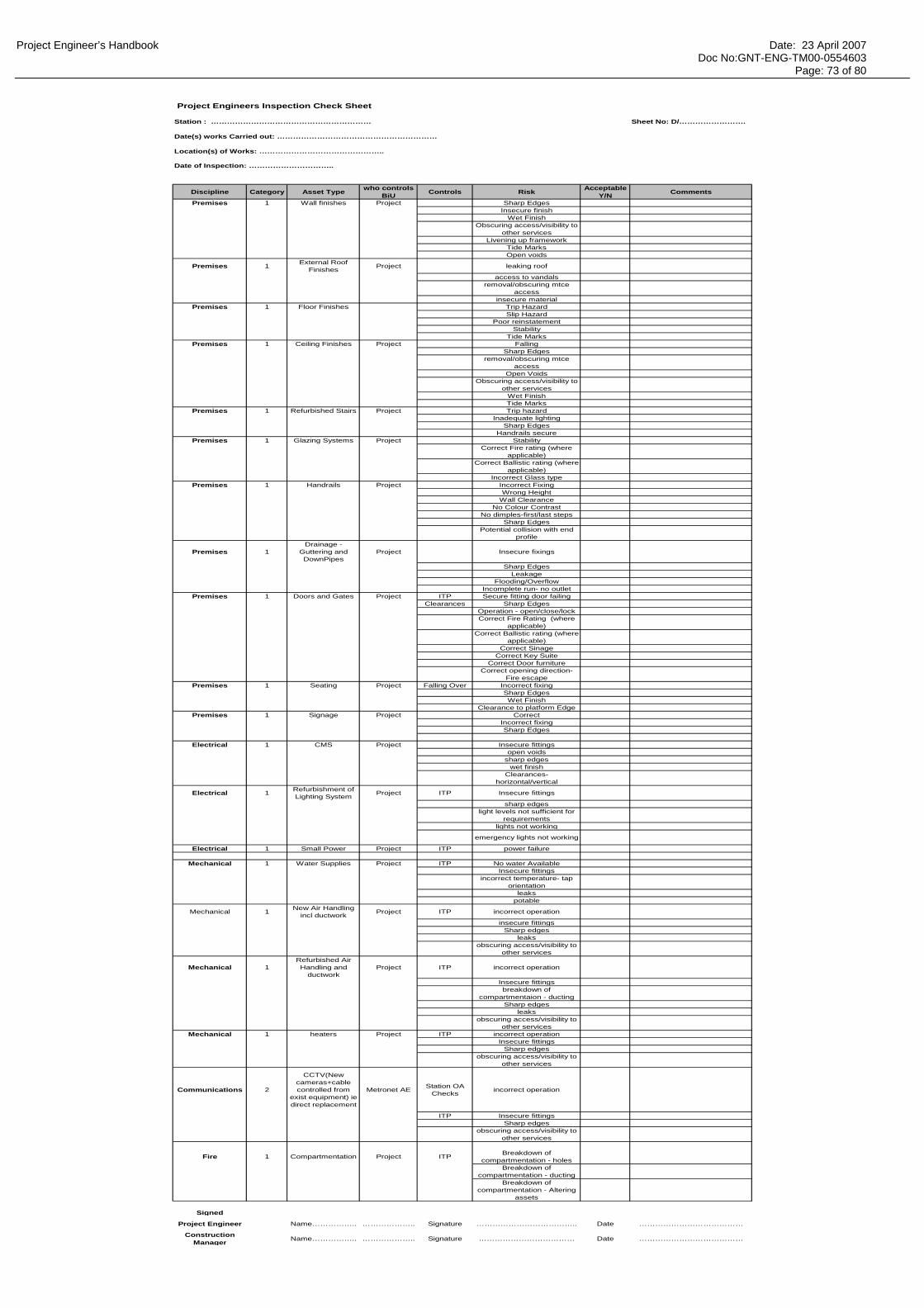
Project Engineer’s Handbook Date: 23 April 2007 Doc No:GNT-ENG-TM00-0554603 Page: 73 of 80
Project Engineers Inspection Check Sheet
Station : …………………………………………………… Sheet No: D/…………………….
Date(s) works Carried out: ……………………………………………………
Location(s) of Works: ………………………………………..
Date of Inspection: …………………………..
Discipline Category Asset Type who controls BiU Controls Risk Acceptable
Y/N Comments
Premises 1 Wall finishes Project Sharp EdgesInsecure finish
Wet FinishObscuring access/visibility to
other servicesLivening up framework
Tide MarksOpen voids
Premises 1 External Roof Finishes Project leaking roof
access to vandalsremoval/obscuring mtce
accessinsecure material
Premises 1 Floor Finishes Trip HazardSlip Hazard
Poor reinstatementStability
Tide MarksPremises 1 Ceiling Finishes Project Falling
Sharp Edgesremoval/obscuring mtce
accessOpen Voids
Obscuring access/visibility to other services
Wet FinishTide Marks
Premises 1 Refurbished Stairs Project Trip hazardInadequate lighting
Sharp EdgesHandrails secure
Premises 1 Glazing Systems Project StabilityCorrect Fire rating (where
applicable)Correct Ballistic rating (where
applicable)Incorrect Glass type
Premises 1 Handrails Project Incorrect FixingWrong Height
Wall ClearanceNo Colour Contrast
No dimples-first/last stepsSharp Edges
Potential collision with end profile
Premises 1Drainage -
Guttering and DownPipes
Project Insecure fixings
Sharp EdgesLeakage
Flooding/OverflowIncomplete run- no outlet
Premises 1 Doors and Gates Project ITP Secure fitting door failingClearances Sharp Edges
Operation - open/close/lockCorrect Fire Rating (where
applicable) Correct Ballistic rating (where
applicable)Correct Sinage
Correct Key SuiteCorrect Door furniture
Correct opening direction- Fire escape
Premises 1 Seating Project Falling Over Incorrect fixingSharp EdgesWet Finish
Clearance to platform EdgePremises 1 Signage Project Correct
Incorrect fixingSharp Edges
Electrical 1 CMS Project Insecure fittingsopen voids
sharp edgeswet finish
Clearances- horizontal/vertical
Electrical 1 Refurbishment of Lighting System Project ITP Insecure fittings
sharp edgeslight levels not sufficient for
requirementslights not working
emergency lights not working
Electrical 1 Small Power Project ITP power failure
Mechanical 1 Water Supplies Project ITP No water AvailableInsecure fittings
incorrect temperature- tap orientation
leakspotable
Mechanical 1 New Air Handling incl ductwork Project ITP incorrect operation
insecure fittingsSharp edges
leaksobscuring access/visibility to
other services
Mechanical 1Refurbished Air Handling and
ductworkProject ITP incorrect operation
Insecure fittingsbreakdown of
compartmentaion - ductingSharp edges
leaksobscuring access/visibility to
other servicesMechanical 1 heaters Project ITP incorrect operation
Insecure fittingsSharp edges
obscuring access/visibility to other services
Communications 2
CCTV(New cameras+cable controlled from
exist equipment) ie direct replacement
Metronet AE Station OA Checks incorrect operation
ITP Insecure fittingsSharp edges
obscuring access/visibility to other services
Fire 1 Compartmentation Project ITP Breakdown of compartmentation - holes
Breakdown of compartmentation - ducting
Breakdown of compartmentation - Altering
assets
Signed
Project Engineer Name…………….. ……………….. Signature ……………………………….. Date …………………………………
Construction Manager Name…………….. ……………….. Signature ……………………………… Date …………………………………
Project Engineer’s Handbook Date: 23 April 2007 Doc No:GNT-ENG-TM00-0554603 Page: 74 of 80
B3 - BiU Cat 3 Assets

Project Engineer’s Handbook Date: 23 April 2007 Doc No:GNT-ENG-TM00-0554603 Page: 75 of 80
BIU CHECKLIST
CompletedY N Comments
General ItemsBiU document approved by LUL - issues log closedGeneric Functional Test Plan in placeATT 1 complete before the BiUATT 2 ready for the BiU
CommsAll works complete ITPs signed off before NOWRI inspectionRed line drawings, signed by affiliate, checked by PEAsset lists - checked by PEACHL files up to dateSnag listsNOWRIs signed off by Chief Engineer/Asset Engineer & Asset PerformanceITPs, red-lines, asset list, basic O&M info accepted by Asset PerformanceS&SD checklistSpexi linesTrain drivers clocksHeritage clocksFull SMSDoor contactsTrain mass detectorsCheck platform VEIDs and other equipment included on Track Clearance ApprovalEMC compliance certsPHP AFIL loopsCCTV playback suiteMetadata on DVR - 14 days of recorded imagesUPS fail testBBMS - functionalTraining - operational Training - maintenance
HFAll works complete NOWRIs signed off by Chiefs Engineers/ Asset Engineers and Asset EngineersHF log closed outTake photos of finished work at BiU for record purposesUser Acceptance Manager inspection complete
Fire All works complete ITPs signedRed line drawings, signed by affiliate, checked by PEAsset lists - checked by PEACHL files up to dateSnag listsNOWRIs signed off by Chief Engineer / Asset Engineer and Asset PerformanceFire stopping certificates, with photos and location drawingFire door certificates for new doors and Bb001 for existingFire extinguishers in SCP/CER/UPSBb224 plan approval in placeBb224 Authority to Use signed by LUL in place (allow 3 days turnaround with LU)Check requirement with Asset Performance to retain redundant equipment
PremisesAll works complete ITPs signedRed line drawings, signed by affiliate, checked by PEAsset lists - checked by PEACHL files up to dateITPs, red-lines, asset list, basic O&M info accepted by Asset PerformanceSnag listsNOWRIs signed off by Chiefs Engineers /Asset Engineers & Asset PerformanceMR-F-10371 (BCG 7) - make sure AIS aware of scope changesSlip test results new and retained floorsSignage
MechanicalAll works complete ITPs signedRed line drawings, signed by affiliate, checked by PEAsset lists - checked by PEACHL files up to dateITPs, red-lines, asset list, basic O&M info accepted by Asset PerformanceSnag listsNOWRIs signed off by Chiefs + Asset PerformanceEMC certs
ElectricalAll works complete ITPs signedRed line drawings, signed by affiliate, checked by PEAsset lists - checked by PEACHL files up to dateITPs, red-lines, asset list, basic O&M info accepted by Asset PerformanceSnag listsNOWRIs signed off by Chief Engineer/Asset Engineer & Asset PerformanceBlock diagrams + red lines must be on siteEDNE signs functionality testLabelling all circuits including DB and earth barLabelling colours - checked by Chief EngineerUPS load testEMC certsLux levels in SCPCER signing in bookHazard signs in CERFirst aid box in UPS room
Third partiesLong line PA - Specialist in Atkins Comms or Assert Maintain -Assurance in placeSCU - Logica/Fentons -Assurance in placePhones/spexi lines - LU IS - Assurance in placeGateline plunger - Prestige Assurance in placeTIM - Connect/Fentons Assurance in place
StructuresAll works completeITPs signedRed line drawings, signed by affiliate, checked by PEACHL files up to dateSnag listsNOWRIs signed off by Chief Engineer/Asset Engineer & Asset Performance

Project Engineer’s Handbook Date: 23 April 2007 Doc No:GNT-ENG-TM00-0554603 Page: 76 of 80
B4 - Engineering Completion Declaration

Project Engineer’s Handbook Date: 23 April 2007 Doc No:GNT-ENG-TM00-0554603 Page: 77 of 80
STATIONS ALLIANCE ENGINEERING NOTICE
Notice No: 025
Rev No: 01
Issue Date: 02/04/07
The purpose of the Stations Alliance Engineering Notice is to communicate or clarify engineering issues which will support the smooth delivery of the stations programme. Applicability to sites (please tick)
All stations
Applicability to Engineering Teams Discipline
SUBJECT Engineering Completion Supporting Information
Background: LU have rejected Engineering Completion Documents because the supporting evidence they expect to be supplied has not been provided. LUL expect the following items to be submitted in support of an Engineering Completion Submission. • Final Lighting Levels • Slip Assessments for floors in public and staff areas
- New floor – SRV test results - Existing Floors (repaired) – HSE assessments before and after works - Existing Floors (not repaired) – HSE assessment
• BCG 7 • Bb224 • Certification that whole station meets separation and compartmentation requirements. • RASTI level survey results • Drainage Survey Results and confirmation of works done Requirements: The attached matrix is to be completed by the Project Engineer and included with every ECD submission. This will advise LU how the required documents have been submitted or if a document is not available, when it will be submitted. The Engineering Team is committed to continuous improvement. If you have any difficulty in applying the content of this notice please send your comments to [email protected]
Prepared By (Print Name): Colin Thomas
Position: Head of Stations Engineering Authority
Sign:
Approved By (Print Name): Mike Willmore
Position: Engineering Director – Civils and Stations
Sign:
L&E
Systems
Human Factors
Fire
Comms
E&M
Structures
EMCPremisesAll
Specific Stations

Project Engineer’s Handbook Date: 23 April 2007 Doc No:GNT-ENG-TM00-0554603 Page: 78 of 80
Station: ………………………………………………………….
Evidence provided in support of Engineering Completion Declaration.
Supporting Document Submitted with ECD
Yes/No
Location of Document
e.g. E-mail, CD etc
If Document is not submitted with ECD, date when it will be issued to
LU.
Comments
Final Lighting Levels
Slip Assessments for Floors in Public and Staff Areas
BCG 7
Bb224
Certification that whole station meets separation and compartmentation requirements.
RASTI level survey results.
Drainage Survey Results and confirmation of works done
I confirm the above information is accurate. Signed:………………………………………….Project Engineer Date:……………………………………………………..

Project Engineer’s Handbook Date: 23 April 2007 Doc No:GNT-ENG-TM00-0554603 Page: 79 of 80
Appendix C

Project Engineer’s Handbook Date: 23 April 2007 Doc No:GNT-ENG-TM00-0554603 Page: 80 of 80
Delivery into Service
Flowchart
DELIVERY INTO SERVICE OF NEW AND ENHANCED FACILITIESPPP Service Contract Schedule 2.1 Appendices 9, 9B & 9C
(notes in brackets [xx] refer to Appendix 9 unless otherwise stated)
Infraco request for Practical Completion [1.1]Infraco issue Draft Snagging List [1.1] and Programme for Completion of Snagging[1.2]
Infraco issue 14 day advance notice of Practical Completion [1.1]
Infraco issue notice of failure to achieve Practical
Completion & advise revised expected date [1.1]
or
LUL give reasons for rejection of Practical
Completion [1.4]
LUL to accept works are
complete within 14 days [1.3]
Appendix 9b: Conditions for Delivery into Service of new or enhancements to Station Facilities to be complied with
Snagging Listaccepted by LUL? [1.4]
LUL issue revised Snagging List to
Infraco [1.4]
Snagging List Date(SLD) [1.4]
Up to 4 Payment Periods (PP)
(after 1st PP end following the SLD)
£10k Abatement per PP for PPs 5 to 10 (after 1st PP end
following the SLD)
Infraco issue 4 week status reports
from 1st Payment Period after SLD
LUL report outstanding Snagging Items to
Fault Reporting Centre [1.7]
Fault Rectification Procedure
[Schedule 2.1 para 3]
SnaggingItems
complete
Appendix 9c: Provision of documents /information relating to DIS of new or enhanced Station Facilities in accordance with the Assurance Plan and Schedule 2.1 clauses 1.9 & 2.8 as a minimum identifying requirements of Appendix 9c 2
PRACTICAL COMPLETION
NO
YES
YES
NO
Snagging Items
complete? [1.6]
YES
NO
Snagging Items
complete? (PPs5-10) [1.6]
NO(PPs 5-9)
YES
DELIVERY INTO SERVICE
COMPLETION OF SNAGGING
Practical Completion
achieved [1.3]
Delivery into Service
NO(PP 10)