Embed Size (px)
Citation preview

Instruction manual
Programmable Automatic Shift System

JRsystems AB, Bäckvägen 18, 19259 Sollentuna, Tel: +46850907300 pg 2
TABLE OF CONTENTS
Section Chapt Page
INTRODUCTION 1 3Nomenclature 1 3Properties 1 3
TECHNICAL DATA 2 4
FUNCTIONS 3 5Automatic shift 3 5Manual shift 3 5Safety features 3 5Other functions 3 6Tachometer 3 7
CONNECTIONS 4 8Connector P1 4 8Connector P2 4 9Connector P3 4 10880170 display unit, measurements 4 10Connector P4 4 11Interface adjustment 4 12Attanuation of signal from magnetic pickup 4 13Using throttle position featurel 4 13
PROGRAMMING 5 14Handling the portable programming unit, PPU 5 14Examine and adjusting parameters 5 14Printer 5 15Adjustable parameters 5 16-20
INSTALLATION 6 21Speed Sensor Kit, SSK 6 21Installation of electronic control unit-ECU 6 21Trouble shooting 6 22Connection sheets 6 23-24Important information 6 25
Shiftronic Instruction manual V2.42 rev5
JRsystems AB, Bäckvägen 18, 19259 Sollentuna, Tel: +46850907300 pg 3
JRsystems AB 2011.08.07
INTRODUCTIONLegend
SHIFTRONIC version 2.00 (part number 880900) consist of the following:ECU Electronic Control Unit – 880903, 880904 and 880905CDU Cab Display Unit - 880170DCK Display Cable Kit - 880-180 2m, -181 3m, -182 4m, -183 5mSSK Speed Sensor Kit - 880116
Other components involved in a SHIFTRONIC application;PPU Portable Programming Unit - 880920PCK Programmer Conversion Kit - 880915CCU Cab control Unit(Shifter) - 875000-, 2-3-400000-series.Printer 880145 (220 V)
880146 (110 V)Printer cable 880144
Features
SHIFTRONIC is a programable electronic device mainly developed for automaticshifting and for protection of powershift-transmission but can also be adapted forspecial applications.
# Analogue input for sensing the throttle position, to activate various functions.
# Simple to programme before and during operation.
# Stabilized and accurate R.P.M monitoring.
# Various types of shift controls (CCU) can be accomodated.
# Both transmission/vehicle- and-engine speed can be monitored.
# Vehicle- and/or acessories malfunction can be detected and displayed.
# Two diffrent ranges (High/Low) with 9 forward and 9 reverse gears.
JRsystems AB, Bäckvägen 18, 19259 Sollentuna, Tel: +46850907300 pg 4
SPECIFICATIONS
Shiftronic Instruction manual V2.42 rev5
Power supply: 12 / 24VDC (10--30VDC).
Enviromental temperature:-40°C--72°C (-40°F--162°F)
Shiftpositions: 9 forward and 9 reverse + high/low range.
Outputs: All inputs/outputs are protected against short-circuit.Max load 1A per outlet, total max load 5A.9 outlets for gear selection.One outlet for engine control.Lock-up. Indication of malfunction.
Inputs: 6 inlets for the cab control unit (CCU).One inlet for monitoring vehicle(transmission) speed.One inlet for manual shift mode.One inlet for sensing the position of the throttle pedal.Lock-up. Inching, Kick-down.2 inlets for indication of malfunction(AUX1;AUX2).One inlet (AUX1) can be used for engine speed monitoring.
Material: Extruded aluminum.
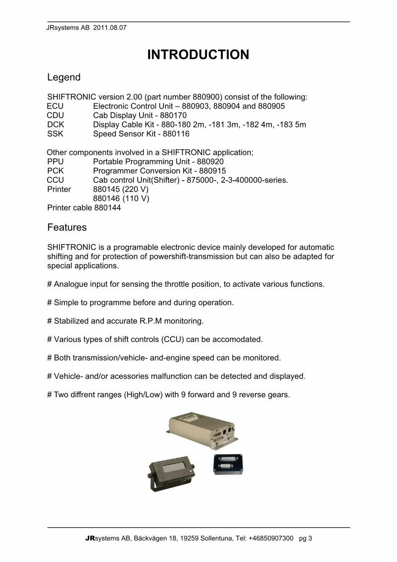
Weight: 880903 - 1.7kg (4.55lbs),880904 and 880905 – 1.7kg (4.55lbs).
Size:

JRsystems AB, Bäckvägen 18, 19259 Sollentuna, Tel: +46850907300 pg 5
JRsystems AB 2011.08.07
FUNCTIONAutomatic shiftSHIFTRONIC constantly monitor the revolution of the propeller- and engine-shaft (ifthe optional mode is selected) and will select appropriate gear according toprogrammed data. In order to prevent continued up- and down-shifting at equalrevolutions of the propeller shaft and of programmed data a hystereses isprogrammable.When the inlet for kick down is activated all speed limit values are increased by acommon percentage.
SHIFTRONIC will not upshift beyond selected gear once chosen by the cab controlunit (CCU). If a gear is selected by the CCU at a moment when the vehicle speed ishigher than programmed value, no shifting will take place until vehicle speed isDecreased.
Manual shiftIf the manual mode is selected SHIFTRONIC will follow selected gears from the CCUregardless of programmed data, except at direction changes.
Security functionsThe following functions are always active in both manual and automatic mode:
Interlock protection:SHIFTRONIC will prevent direction changes or shifting from neutral into gear if speedof the vehicle exceeds programmed data.The display shows REV.
Malfunction:The malfunction inlets (AUX 1; AUX 2) can be programmed in various ways. Alwaysdetected or only when a gear is engaged. They can optionally activate the enginecontrol and/or the malfunction outlets. The display shows a programmable text, e.g.ERROR.
Engine R.P.M.:If engine revolutions are to be monitored one of the malfunction inlets (AUX 1) isused. Two different R.P.M. limits are compared.The maximum permitted R.P.M. ofthe engine is always monitored by SHIFTRONIC. When the programmed limit isexceeded the transmission will automatically shift into neutral and both enginecontrol- and malfunction-outlet will be activated according to selected programmedfunctions. The display shows RPM.
The maximum permitted start engine R.P.M. is only monitored when a gear isengaged after being in neutral. Resulting effect is as described above. The displayshows RPM.

JRsystems AB, Bäckvägen 18, 19259 Sollentuna, Tel: +46850907300 pg 6
Speed sensor:When the propeller shaft R.P.M exceeds a preset limit the pulses are monitored by theECU to ensure that they are regular. If the pulses for any reason, should be irregularor non existant the ECU will interpret it as a sensor failure. The transmission willautomatically shift into neutral and the malfunction outlet will be activated. The displayshows SENS.
Short circuit:The ECU is protected against short circuits at all outlets. If a short circuit shouldoccur or if each outlet is loaded with more than 1A (totally 4A), all outlets will bedeactivated to prevent false gearshifting etc. The display shows AMP.
Other functions
Malfunction mode:If any of above security functions have been activated and a normal circuit activationis subsequently switched on, the ECU should either be shifted into neutral or couldremain in previous position depending on programmed function before starting again.(ERROR KEEP GEAR)
Rev. prot. mode:It is possible to select the following mode: If the CCU is shifted from an engagedgear into neutral when the vehicle is in progress, it can be possible to return toprevious gear but only if the vehicle is in the permitted speed range according toprogrammed value. (REENTER IF REV)
Lock-up:The inlet signal for lock-up corresponds directly to the lock-up outlet, exceptimmediately before and after the lockup is engaged. The time delay is programmable.
Inching:When the inching input is activated, Shiftronic selects neutral-position. Whendeactivated Shiftronic astivates the engine start rpm, to prevent any gear to beengaged at too hich engine speed. The inching cirquit can be normally closed orOpen.
Engine control:The engine control outlet is activated immediately before and after a gear is engagedto provide smooth gear shifting. The time delay is programmable. It is possible to havea common or a separate value for each gear shift. It is also possible toprogram the engine control not to be activated when down-shifting, and/or down-shifting when the kick down inlet is activated.Furthermore it is possible to have theengine control activated when diffrent malfunctions occur.Although the different timeintervals described above are not necessary to control gear shifting and lock-upengagement, the time is monitored anyway. Consequently there has to be a minimumtime before gear- and lock-up-engagement can take place.
Shiftronic Instruction manual V2.42 rev5
JRsystems AB, Bäckvägen 18, 19259 Sollentuna, Tel: +46850907300 pg 7
JRsystems AB 2011.08.07
Special application:To control various other vehicle functions as 4-wheel drive etc., which should not beactivated before the transmission is in it's neutral position and/or before the vehiclehas come to a complete stop, it is possible to receive a signal from the ECU whenthe transmission is in neutral and when the propeller shaft R.P.M is belowprogrammed value of the interlock protection (REV PROT).
Tachometer:To simplify programming of the different speed values the ECU is prepared to displaythe present R.P.M of the transmission- and engine-shafts. This function is activatedby pressing one of the reset buttons situated on the ECU's front panel or on the CDUfront cover. The display will initially show TRANS for a moment, and thenautomatically follow with the present R.P.M of the transmission shaft. By pressing oneof the reset buttons a second time the display will return to it's default mode. Toreceive information of the engine shaft R.P.M, one of the reset buttons has to bepressed a third time. The display will show MOTOR for a moment before the engineR.P.M is displayed.
JRsystems AB, Bäckvägen 18, 19259 Sollentuna, Tel: +46850907300 pg 8
Shiftronic Instruction manual V2.42 rev5
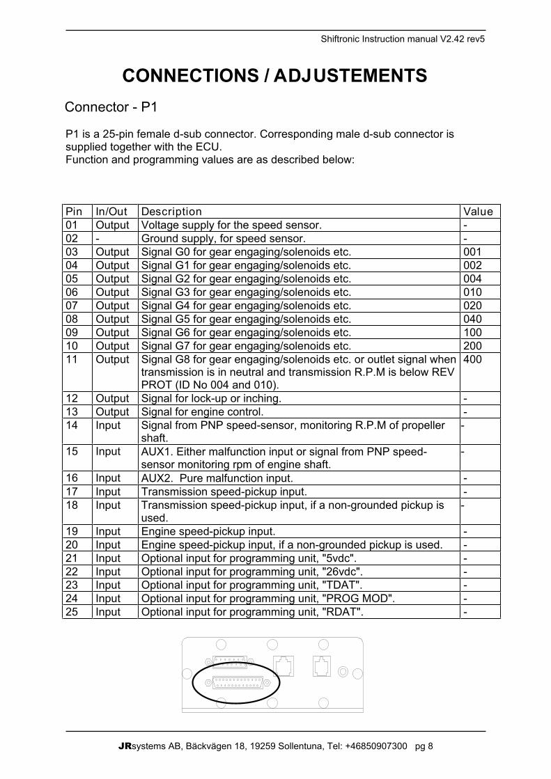
CONNECTIONS / ADJUSTEMENTSConnector - P1
P1 is a 25-pin female d-sub connector. Corresponding male d-sub connector issupplied together with the ECU.Function and programming values are as described below:
Pin In/Out Description Value01 Output Voltage supply for the speed sensor. -02 - Ground supply, for speed sensor. -03 Output Signal G0 for gear engaging/solenoids etc. 00104 Output Signal G1 for gear engaging/solenoids etc. 00205 Output Signal G2 for gear engaging/solenoids etc. 00406 Output Signal G3 for gear engaging/solenoids etc. 01007 Output Signal G4 for gear engaging/solenoids etc. 02008 Output Signal G5 for gear engaging/solenoids etc. 04009 Output Signal G6 for gear engaging/solenoids etc. 10010 Output Signal G7 for gear engaging/solenoids etc. 20011 Output Signal G8 for gear engaging/solenoids etc. or outlet signal when 400
transmission is in neutral and transmission R.P.M is below REVPROT (ID No 004 and 010).
12 Output Signal for lock-up or inching. -13 Output Signal for engine control. -14 Input Signal from PNP speed-sensor, monitoring R.P.M of propeller
shaft.-
15 Input AUX1. Either malfunction input or signal from PNP speed-sensor monitoring rpm of engine shaft.
-
16 Input AUX2. Pure malfunction input. -17 Input Transmission speed-pickup input. -18 Input Transmission speed-pickup input, if a non-grounded pickup is
used.-
19 Input Engine speed-pickup input. -20 Input Engine speed-pickup input, if a non-grounded pickup is used. -21 Input Optional input for programming unit, "5vdc". -22 Input Optional input for programming unit, "26vdc". -23 Input Optional input for programming unit, "TDAT". -24 Input Optional input for programming unit, "PROG MOD". -25 Input Optional input for programming unit, "RDAT". -
JRsystems AB, Bäckvägen 18, 19259 Sollentuna, Tel: +46850907300 pg 9
JRsystems AB 2011.08.07
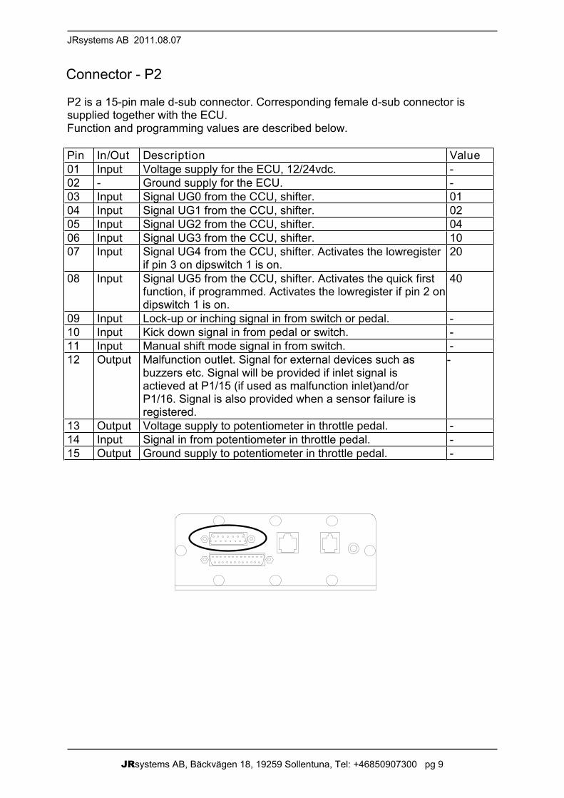
Connector - P2
P2 is a 15-pin male d-sub connector. Corresponding female d-sub connector issupplied together with the ECU.Function and programming values are described below.
Pin In/Out Description Value01 Input Voltage supply for the ECU, 12/24vdc. -02 - Ground supply for the ECU. -03 Input Signal UG0 from the CCU, shifter. 0104 Input Signal UG1 from the CCU, shifter. 0205 Input Signal UG2 from the CCU, shifter. 0406 Input Signal UG3 from the CCU, shifter. 1007 Input Signal UG4 from the CCU, shifter. Activates the lowregister 20
if pin 3 on dipswitch 1 is on.08 Input Signal UG5 from the CCU, shifter. Activates the quick first
function, if programmed. Activates the lowregister if pin 2 ondipswitch 1 is on.
40
09 Input Lock-up or inching signal in from switch or pedal. -10 Input Kick down signal in from pedal or switch. -11 Input Manual shift mode signal in from switch. -12 Output Malfunction outlet. Signal for external devices such as
buzzers etc. Signal will be provided if inlet signal isactieved at P1/15 (if used as malfunction inlet)and/orP1/16. Signal is also provided when a sensor failure isregistered.
-
13 Output Voltage supply to potentiometer in throttle pedal. -14 Input Signal in from potentiometer in throttle pedal. -15 Output Ground supply to potentiometer in throttle pedal. -
JRsystems AB, Bäckvägen 18, 19259 Sollentuna, Tel: +46850907300 pg 10
Shiftronic Instruction manual V2.42 rev5
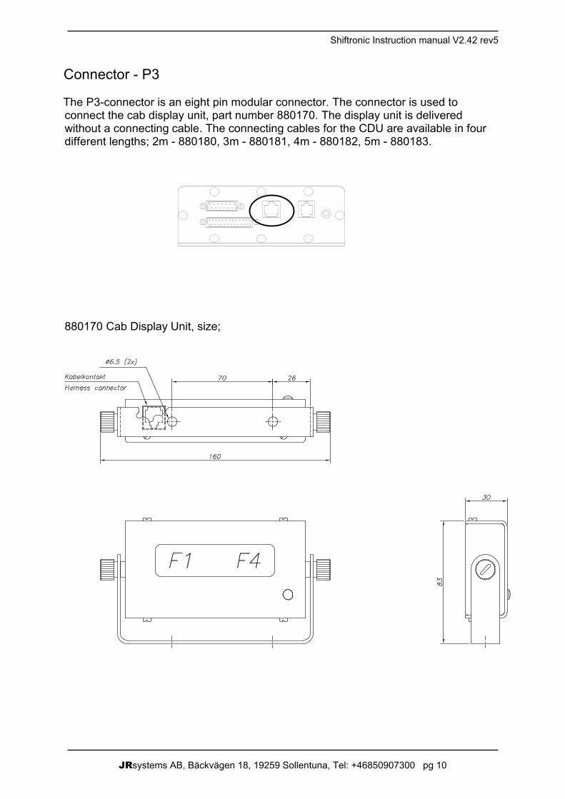
Connector - P3
The P3-connector is an eight pin modular connector. The connector is used toconnect the cab display unit, part number 880170. The display unit is deliveredwithout a connecting cable. The connecting cables for the CDU are available in fourdifferent lengths; 2m - 880180, 3m - 880181, 4m - 880182, 5m - 880183.
880170 Cab Display Unit, size;
JRsystems AB, Bäckvägen 18, 19259 Sollentuna, Tel: +46850907300 pg 11
JRsystems AB 2011.08.07
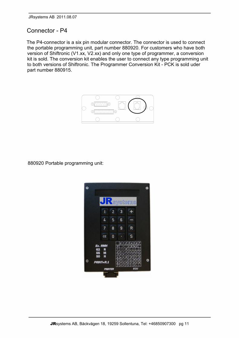
Connector - P4
The P4-connector is a six pin modular connector. The connector is used to connectthe portable programming unit, part number 880920. For customers who have bothversion of Shiftronic (V1.xx, V2.xx) and only one type of programmer, a conversionkit is sold. The conversion kit enables the user to connect any type programming unitto both versions of Shiftronic. The Programmer Conversion Kit - PCK is sold uderpart number 880915.
880920 Portable programming unit:
JRsystems AB, Bäckvägen 18, 19259 Sollentuna, Tel: +46850907300 pg 12
Shiftronic Instruction manual V2.42 rev5
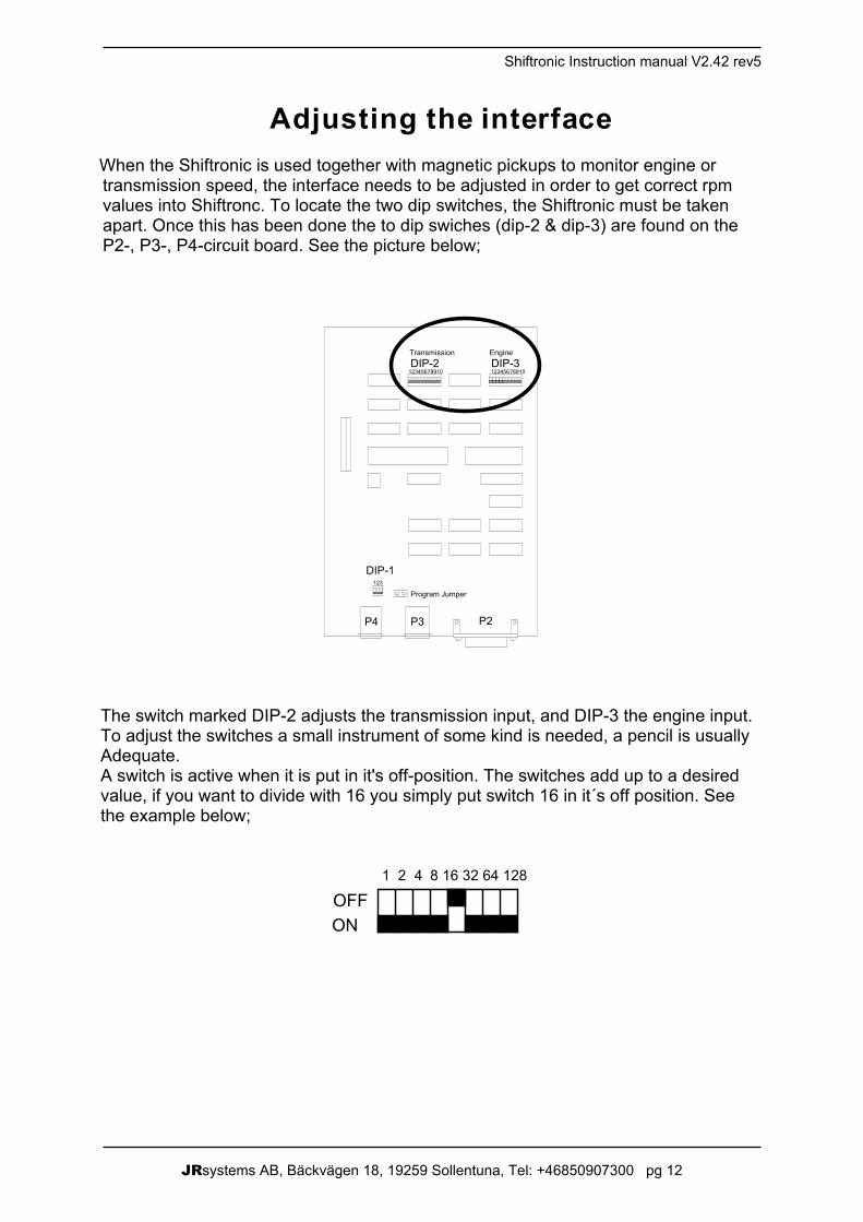
Adjusting the interfaceWhen the Shiftronic is used together with magnetic pickups to monitor engine ortransmission speed, the interface needs to be adjusted in order to get correct rpmvalues into Shiftronc. To locate the two dip switches, the Shiftronic must be takenapart. Once this has been done the to dip swiches (dip-2 & dip-3) are found on theP2-, P3-, P4-circuit board. See the picture below;
Program Jumper
DIP-1
DIP-2 DIP-3
P4 P3 P2
123
12345678910 12345678910
EngineTransmission
The switch marked DIP-2 adjusts the transmission input, and DIP-3 the engine input.To adjust the switches a small instrument of some kind is needed, a pencil is usuallyAdequate.A switch is active when it is put in it's off-position. The switches add up to a desiredvalue, if you want to divide with 16 you simply put switch 16 in it´s off position. Seethe example below;
ONOFF
1 2 4 8 16 32 64 128
JRsystems AB, Bäckvägen 18, 19259 Sollentuna, Tel: +46850907300 pg 13
JRsystems AB 2011.08.07
Attenuation of the signal from a magnetic pickup
The signal from the magnetic-pickup could be disturbed, when the pickup is used tomonitor transmission or engine speed. If that is the case, Shiftronic has a attenuationfeature that could take care of the problem. The general idea is when you damp thesignal coming in, you also damp the disturbances coming in. The attenuation isseparate between the transmission and engine.To activate follow the function you have to disassemble the Shiftronic box, when thisis done you find a dip switch on the P1 circuit board. The switch has two channels,1=Engine2=Transmision. To activate the attenuation function you simply slide the switch fromit's off position to on.The factory preset is both channels- attenuation off.
Using the throttle-position feature
The Shiftronic V2.40 is equipped with an analogue input for sensing the position ofthe throttle pedal. The input is used to activate the Shiftronics lowregister for enginebraking, and/or kickdown feature.Shiftronic constantly monitors the input, and activates the lowregister/kickdown at theadjusted positions. To adjust the activating position there are two trim-potentiometers, one for lowregister- & one for kickdown-position. The function isselected with a dip switch. To activate and adjust the function, follow the instructionbelow;
To activate the function the Shiftronic box has to be disassembled. Once this hasbeen done, a switch can be found on the P2-, P3- & P4-circuit board.The dip switch adjusts the function of the analogue input. The switch has threechannels.1=Activate the kickdown function with the analogue input.2=Activate the lowregister (P2/8) with the analogue input.3=Activate the lowregister (P2/7) with the analogue input.
The two trim potentiometers adjusts the throttle-position where the function is to beactivated. The potentiometers are marked P1 & P2, and are found on the P1 circuitboard.P1 adjusts the kickdown feature. If the potentiometer is turned clockwise, theactivation point is moved towards the end of the throttle-pedals travel.P2 adjusts the lowregister feature. If the potentiometer is turned anti-clockwise, theactivation point is moved towards the beginning of the throttle pedals travel.
JRsystems AB, Bäckvägen 18, 19259 Sollentuna, Tel: +46850907300 pg 14
Shiftronic Instruction manual V2.42 rev5
PROGRAMMING.
Handling the portable programming unit PPU.Connect the programmer to connector P4 on Shiftronic.By connecting a printer to the PPU is possible to get a print out, of currentparammeters in the Shiftronic.The ECU should be switched off before the PPU is connected. When supply isswitched on again after connecting the PPU, the display will show SHIFTRONICV1.XX, XX represents the version of the program that is in the Shiftronic.Note! If the version number of your Shiftronic is different from the one at the top ofevery page in the manual, your manual may be old. Contact your dealer to recieve anew copy.
Examine and adjusting parameters.
By pressing the following push buttons on PPU the following functions will beachieved:
+The parameters will appear on the display of the PPU in sequence until the end(END) of the programme is reached. By pressing the button again the program willrestart from the beginning.
-As above but the parameters will appear in reverse order.
REach parameters has its own identification number, which will be shown on thedisplay of the PPU as soon as the R is pressed.
RXXRBy pressing the buttons in this sequence it is possible to jump directly to requiredparameter.XX = Parameter identification number.
SAfter finding required parameter to be modified and after the new value is enteredthe push button S has to be pressed, to Save the new value.
CEIf an incorrect value is entered, simply press the CE button and the previous valuewill reappear on the display of the PPU.
Textthe text parameters are entered by special number sequences as the legend isshowing on the PPU. The text TEMP is entered by the number sequence : 64, 45,55, 60.
JRsystems AB, Bäckvägen 18, 19259 Sollentuna, Tel: +46850907300 pg 15
JRsystems AB 2011.08.07
PrintPrinting is started by pressing the following sequence on the push buttonson the PPU;”R . 1”, (R dot one).
Printer technical data.Interface connector:All signals according to V24. Pin 2 TD - Data outlet to printer, 1200 baud. Pin 5 CTS - "Ready" signal from printer.Pin 7 SG - Ground signal.
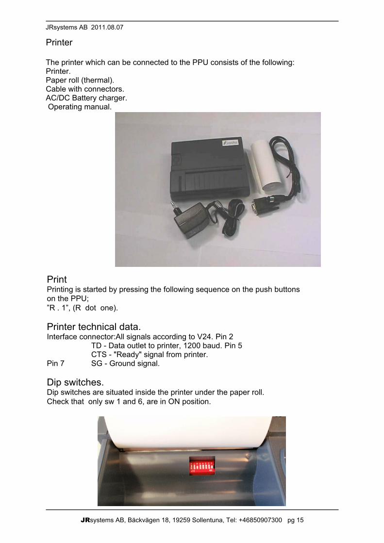
Dip switches.Dip switches are situated inside the printer under the paper roll.Check that only sw 1 and 6, are in ON position.
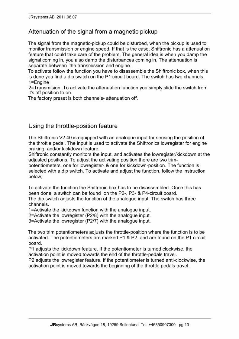
Printer
The printer which can be connected to the PPU consists of the following:Printer.Paper roll (thermal).Cable with connectors.AC/DC Battery charger. Operating manual.
JRsystems AB, Bäckvägen 18, 19259 Sollentuna, Tel: +46850907300 pg 16
Shiftronic Instruction manual V2.42 rev5
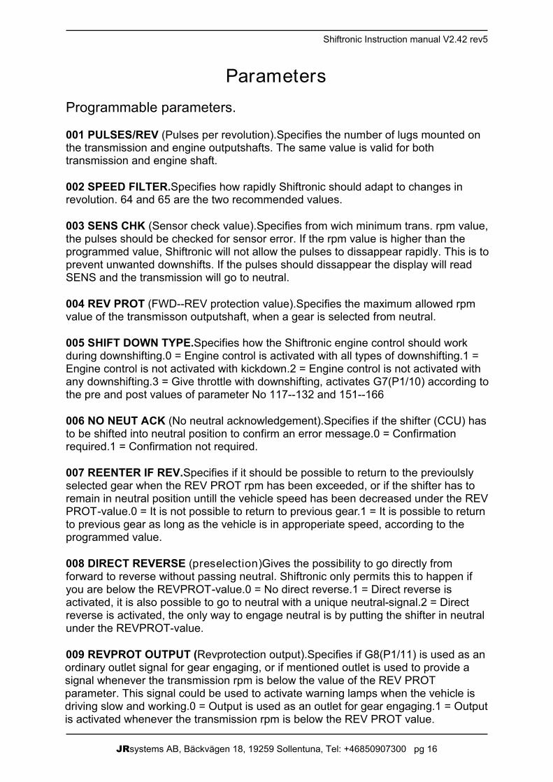
ParametersProgrammable parameters.
001 PULSES/REV (Pulses per revolution).Specifies the number of lugs mounted onthe transmission and engine outputshafts. The same value is valid for bothtransmission and engine shaft.
002 SPEED FILTER.Specifies how rapidly Shiftronic should adapt to changes inrevolution. 64 and 65 are the two recommended values.
003 SENS CHK (Sensor check value).Specifies from wich minimum trans. rpm value,the pulses should be checked for sensor error. If the rpm value is higher than theprogrammed value, Shiftronic will not allow the pulses to dissappear rapidly. This is toprevent unwanted downshifts. If the pulses should dissappear the display will readSENS and the transmission will go to neutral.
004 REV PROT (FWD--REV protection value).Specifies the maximum allowed rpmvalue of the transmisson outputshaft, when a gear is selected from neutral.
005 SHIFT DOWN TYPE.Specifies how the Shiftronic engine control should workduring downshifting.0 = Engine control is activated with all types of downshifting.1 =Engine control is not activated with kickdown.2 = Engine control is not activated withany downshifting.3 = Give throttle with downshifting, activates G7(P1/10) according tothe pre and post values of parameter No 117--132 and 151--166
006 NO NEUT ACK (No neutral acknowledgement).Specifies if the shifter (CCU) hasto be shifted into neutral position to confirm an error message.0 = Confirmationrequired.1 = Confirmation not required.
007 REENTER IF REV.Specifies if it should be possible to return to the previoulslyselected gear when the REV PROT rpm has been exceeded, or if the shifter has toremain in neutral position untill the vehicle speed has been decreased under the REVPROT -value.0 = It is not possible to return to previous gear.1 = It is possible to returnto previous gear as long as the vehicle is in approperiate speed, according to theprogrammed value.
008 DIRECT REVERSE (preselection)Gives the possibility to go directly fromforward to reverse without passing neutral. Shiftronic only permits this to happen ifyou are below the REVPROT -value.0 = No direct reverse.1 = Direct reverse isactivated, it is also possible to go to neutral with a unique neutral-signal.2 = Directreverse is activated, the only way to engage neutral is by putting the shifter in neutralunder the REVPROT-value.
009 REVPROT OUTPUT (Revprotection output).Specifies if G8(P1/11) is used as anordinary outlet signal for gear engaging, or if mentioned outlet is used to provide asignal whenever the transmission rpm is below the value of the REV PROTparameter. This signal could be used to activate warning lamps when the vehicle isdriving slow and working.0 = Output is used as an outlet for gear engaging.1 = Outputis activated whenever the transmission rpm is below the REV PROT value.
JRsystems AB, Bäckvägen 18, 19259 Sollentuna, Tel: +46850907300 pg 17
JRsystems AB 2011.08.07
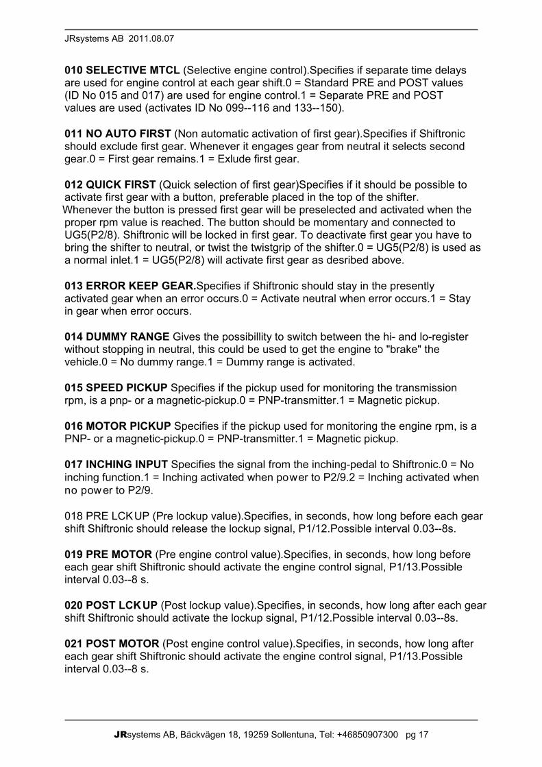
010 SELECTIVE MTCL (Selective engine control).Specifies if separate time delaysare used for engine control at each gear shift.0 = Standard PRE and POST values(ID No 015 and 017) are used for engine control.1 = Separate PRE and POSTvalues are used (activates ID No 099--116 and 133--150).
011 NO AUTO FIRST (Non automatic activation of first gear).Specifies if Shiftronicshould exclude first gear. Whenever it engages gear from neutral it selects secondgear.0 = First gear remains.1 = Exlude first gear.
012 QUICK FIRST (Quick selection of first gear)Specifies if it should be possible toactivate first gear with a button, preferable placed in the top of the shifter.Whenever the button is pressed first gear will be preselected and activated when theproper rpm value is reached. The button should be momentary and connected toUG5(P2/8). Shiftronic will be locked in first gear. To deactivate first gear you have tobring the shifter to neutral, or twist the twistgrip of the shifter.0 = UG5(P2/8) is used asa normal inlet.1 = UG5(P2/8) will activate first gear as desribed above.
013 ERROR KEEP GEAR.Specifies if Shiftronic should stay in the presentlyactivated gear when an error occurs.0 = Activate neutral when error occurs.1 = Stayin gear when error occurs.
014 DUMMY RANGE Gives the possibillity to switch between the hi- and lo-registerwithout stopping in neutral, this could be used to get the engine to "brake" thevehicle.0 = No dummy range.1 = Dummy range is activated.
015 SPEED PICKUP Specifies if the pickup used for monitoring the transmissionrpm, is a pnp- or a magnetic-pickup.0 = PNP-transmitter.1 = Magnetic pickup.
016 MOTOR PICKUP Specifies if the pickup used for monitoring the engine rpm, is aPNP- or a magnetic-pickup.0 = PNP-transmitter.1 = Magnetic pickup.
017 INCHING INPUT Specifies the signal from the inching-pedal to Shiftronic.0 = Noinching function.1 = Inching activated when power to P2/9.2 = Inching activated whenno power to P2/9.
018 PRE LCKUP (Pre lockup value).Specifies, in seconds, how long before each gearshift Shiftronic should release the lockup signal, P1/12.Possible interval 0.03--8s.
019 PRE MOTOR (Pre engine control value).Specifies, in seconds, how long beforeeach gear shift Shiftronic should activate the engine control signal, P1/13.Possibleinterval 0.03--8 s.
020 POST LCKUP (Post lockup value).Specifies, in seconds, how long after each gearshift Shiftronic should activate the lockup signal, P1/12.Possible interval 0.03--8s.
021 POST MOTOR (Post engine control value).Specifies, in seconds, how long aftereach gear shift Shiftronic should activate the engine control signal, P1/13.Possibleinterval 0.03--8 s.
JRsystems AB, Bäckvägen 18, 19259 Sollentuna, Tel: +46850907300 pg 18
Shiftronic Instruction manual V2.42 rev5
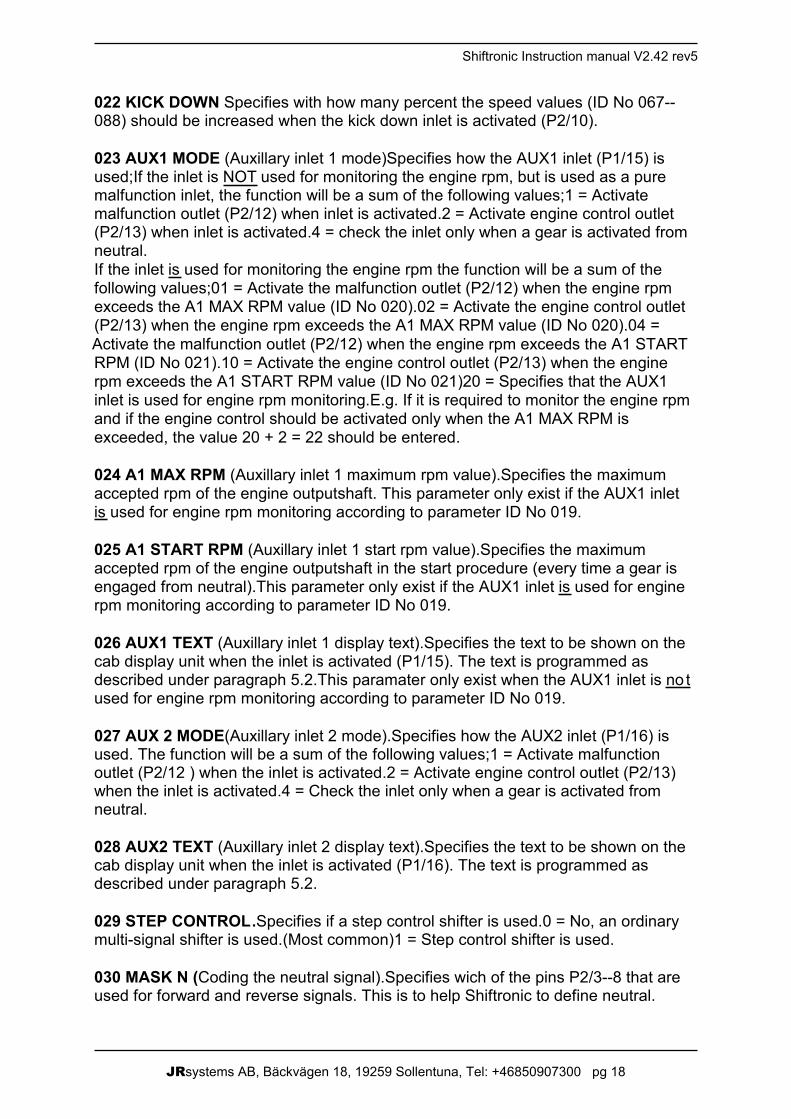
022 KICK DOWN Specifies with how many percent the speed values (ID No 067--088) should be increased when the kick down inlet is activated (P2/10).
023 AUX1 MODE (Auxillary inlet 1 mode)Specifies how the AUX1 inlet (P1/15) isused;If the inlet is NOT used for monitoring the engine rpm, but is used as a puremalfunction inlet, the function will be a sum of the following values;1 = Activatemalfunction outlet (P2/12) when inlet is activated.2 = Activate engine control outlet(P2/13) when inlet is activated.4 = check the inlet only when a gear is activated fromneutral.If the inlet is used for monitoring the engine rpm the function will be a sum of thefollowing values;01 = Activate the malfunction outlet (P2/12) when the engine rpmexceeds the A1 MAX RPM value (ID No 020).02 = Activate the engine control outlet(P2/13) when the engine rpm exceeds the A1 MAX RPM value (ID No 020).04 =Activate the malfunction outlet (P2/12) when the engine rpm exceeds the A1 STARTRPM (ID No 021).10 = Activate the engine control outlet (P2/13) when the enginerpm exceeds the A1 START RPM value (ID No 021)20 = Specifies that the AUX1inlet is used for engine rpm monitoring.E.g. If it is required to monitor the engine rpmand if the engine control should be activated only when the A1 MAX RPM isexceeded, the value 20 + 2 = 22 should be entered.
024 A1 MAX RPM (Auxillary inlet 1 maximum rpm value).Specifies the maximumaccepted rpm of the engine outputshaft. This parameter only exist if the AUX1 inletis used for engine rpm monitoring according to parameter ID No 019.
025 A1 START RPM (Auxillary inlet 1 start rpm value).Specifies the maximumaccepted rpm of the engine outputshaft in the start procedure (every time a gear isengaged from neutral).This parameter only exist if the AUX1 inlet is used for enginerpm monitoring according to parameter ID No 019.
026 AUX1 TEXT (Auxillary inlet 1 display text).Specifies the text to be shown on thecab display unit when the inlet is activated (P1/15). The text is programmed asdescribed under paragraph 5.2.This paramater only exist when the AUX1 inlet is no tused for engine rpm monitoring according to parameter ID No 019.
027 AUX 2 MODE(Auxillary inlet 2 mode).Specifies how the AUX2 inlet (P1/16) isused. The function will be a sum of the following values;1 = Activate malfunctionoutlet (P2/12 ) when the inlet is activated.2 = Activate engine control outlet (P2/13)when the inlet is activated.4 = Check the inlet only when a gear is activated fromneutral.
028 AUX2 TEXT (Auxillary inlet 2 display text).Specifies the text to be shown on thecab display unit when the inlet is activated (P1/16). The text is programmed asdescribed under paragraph 5.2.
029 STEP CONTROL .Specifies if a step control shifter is used.0 = No, an ordinarymulti-signal shifter is used.(Most common)1 = Step control shifter is used.
030 MASK N (Coding the neutral signal).Specifies wich of the pins P2/3--8 that areused for forward and reverse signals. This is to help Shiftronic to define neutral.
JRsystems AB, Bäckvägen 18, 19259 Sollentuna, Tel: +46850907300 pg 19
JRsystems AB 2011.08.07
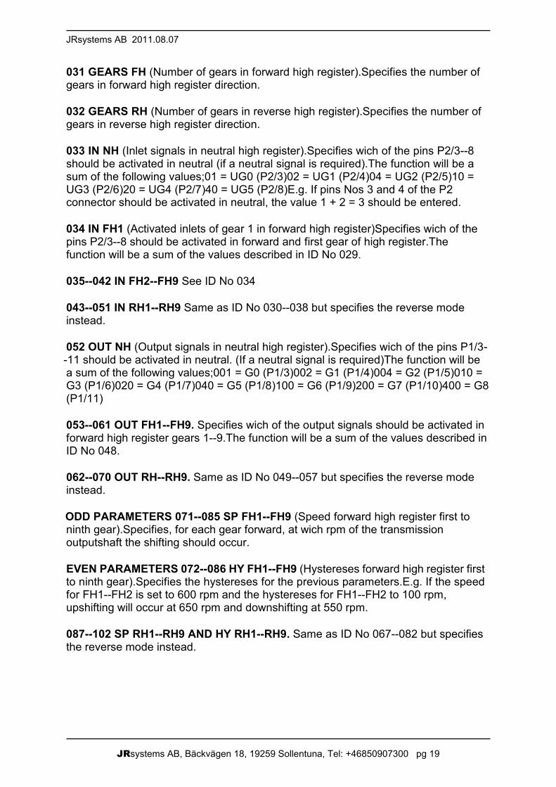
031 GEARS FH (Number of gears in forward high register).Specifies the number ofgears in forward high register direction.
032 GEARS RH (Number of gears in reverse high register).Specifies the number ofgears in reverse high register direction.
033 IN NH (Inlet signals in neutral high register).Specifies wich of the pins P2/3--8should be activated in neutral (if a neutral signal is required).The function will be asum of the following values;01 = UG0 (P2/3)02 = UG1 (P2/4)04 = UG2 (P2/5)10 =UG3 (P2/6)20 = UG4 (P2/7)40 = UG5 (P2/8)E.g. If pins Nos 3 and 4 of the P2connector should be activated in neutral, the value 1 + 2 = 3 should be entered.
034 IN FH1 (Activated inlets of gear 1 in forward high register)Specifies wich of thepins P2/3--8 should be activated in forward and first gear of high register.Thefunction will be a sum of the values described in ID No 029.
035--042 IN FH2--FH9 See ID No 034
043--051 IN RH1--RH9 Same as ID No 030--038 but specifies the reverse modeinstead.
052 OUT NH (Output signals in neutral high register).Specifies wich of the pins P1/3--11 should be activated in neutral. (If a neutral signal is required)The function will bea sum of the following values;001 = G0 (P1/3)002 = G1 (P1/4)004 = G2 (P1/5)010 =G3 (P1/6)020 = G4 (P1/7)040 = G5 (P1/8)100 = G6 (P1/9)200 = G7 (P1/10)400 = G8(P1/11)
053--061 OUT FH1--FH9. Specifies wich of the output signals should be activated inforward high register gears 1--9.The function will be a sum of the values described inID No 048.
062--070 OUT RH--RH9. Same as ID No 049--057 but specifies the reverse modeinstead.
ODD PARAMETERS 071--085 SP FH1--FH9 (Speed forward high register first toninth gear).Specifies, for each gear forward, at wich rpm of the transmissionoutputshaft the shifting should occur.
EVEN PARAMETERS 072--086 HY FH1--FH9 (Hystereses forward high register firstto ninth gear).Specifies the hystereses for the previous parameters.E.g. If the speedfor FH1--FH2 is set to 600 rpm and the hystereses for FH1--FH2 to 100 rpm,upshifting will occur at 650 rpm and downshifting at 550 rpm.
087--102 SP RH1--RH9 AND HY RH1--RH9. Same as ID No 067--082 but specifiesthe reverse mode instead.
JRsystems AB, Bäckvägen 18, 19259 Sollentuna, Tel: +46850907300 pg 20
Shiftronic Instruction manual V2.42 rev5
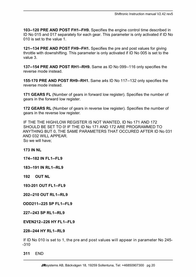
103--120 PRE AND POST FH1--FH9. Specifies the engine control time described inID No 015 and 017 separately for each gear. This parameter is only activated if ID No010 is set to the value 1.
121--134 PRE AND POST FH9--FH1. Specifies the pre and post values for givingthrottle with downshifting. This parameter is only activated if ID No 005 is set to thevalue 3.
137--154 PRE AND POST RH1--RH9. Same as ID No 099--116 only specifies thereverse mode instead.
155-170 PRE AND POST RH9--RH1. Same a4s ID No 117--132 only specifies thereverse mode instead.
171 GEARS FL (Number of gears in forward low register). Specifies the number ofgears in the forward low register.
172 GEARS RL (Number of gears in reverse low register). Specifies the number ofgears in the reverse low register.
IF THE THE HIGH/LOW REGISTER IS NOT WANTED, ID No 171 AND 172SHOULD BE SET TO 0! IF THE ID No 171 AND 172 ARE PROGRAMMED TOANYTHING BUT 0, THE SAME PARAMETERS THAT OCCURED AFTER ID No 031AND 032 WILL APPEAR.So we will have;
173 IN NL
174--182 IN FL1--FL9
183--191 IN RL1--RL9
192 OUT NL
193-201 OUT FL1--FL9
202--210 OUT RL1--RL9
ODD211--225 SP FL1--FL9
227--243 SP RL1--RL9
EVEN212--226 HY FL1--FL9
228--244 HY RL1--RL9
If ID No 010 is set to 1, the pre and post values will appear in parameter No 245--310
311 END
JRsystems AB, Bäckvägen 18, 19259 Sollentuna, Tel: +46850907300 pg 21
JRsystems AB 2011.08.07
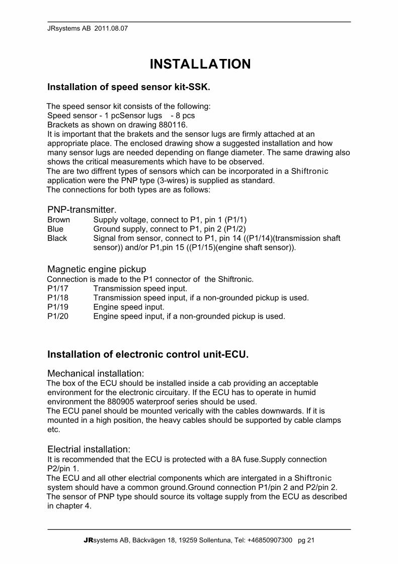
INSTALLATIONInstallation of speed sensor kit-SSK.
The speed sensor kit consists of the following:Speed sensor - 1 pcSensor lugs - 8 pcsBrackets as shown on drawing 880116.It is important that the brakets and the sensor lugs are firmly attached at anappropriate place. The enclosed drawing show a suggested installation and howmany sensor lugs are needed depending on flange diameter. The same drawing alsoshows the critical measurements which have to be observed.The are two diffrent types of sensors which can be incorporated in a Shiftronicapplication were the PNP type (3-wires) is supplied as standard.The connections for both types are as follows:
PNP-transmitter.Brown Supply voltage, connect to P1, pin 1 (P1/1)Blue Ground supply, connect to P1, pin 2 (P1/2)Black Signal from sensor, connect to P1, pin 14 ((P1/14)(transmission shaft
sensor)) and/or P1,pin 15 ((P1/15)(engine shaft sensor)).
Magnetic engine pickupConnection is made to the P1 connector of the Shiftronic.P1/17 Transmission speed input.P1/18 Transmission speed input, if a non-grounded pickup is used.P1/19 Engine speed input.P1/20 Engine speed input, if a non-grounded pickup is used.
Installation of electronic control unit-ECU.
Mechanical installation:The box of the ECU should be installed inside a cab providing an acceptableenvironment for the electronic circuitary. If the ECU has to operate in humidenvironment the 880905 waterproof series should be used.The ECU panel should be mounted verically with the cables downwards. If it ismounted in a high position, the heavy cables should be supported by cable clampsetc.
Electrial installation:It is recommended that the ECU is protected with a 8A fuse.Supply connectionP2/pin 1.The ECU and all other electrial components which are intergated in a Shiftronicsystem should have a common ground.Ground connection P1/pin 2 and P2/pin 2.The sensor of PNP type should source its voltage supply from the ECU as describedin chapter 4.
JRsystems AB, Bäckvägen 18, 19259 Sollentuna, Tel: +46850907300 pg 22
Shiftronic Instruction manual V2.42 rev5
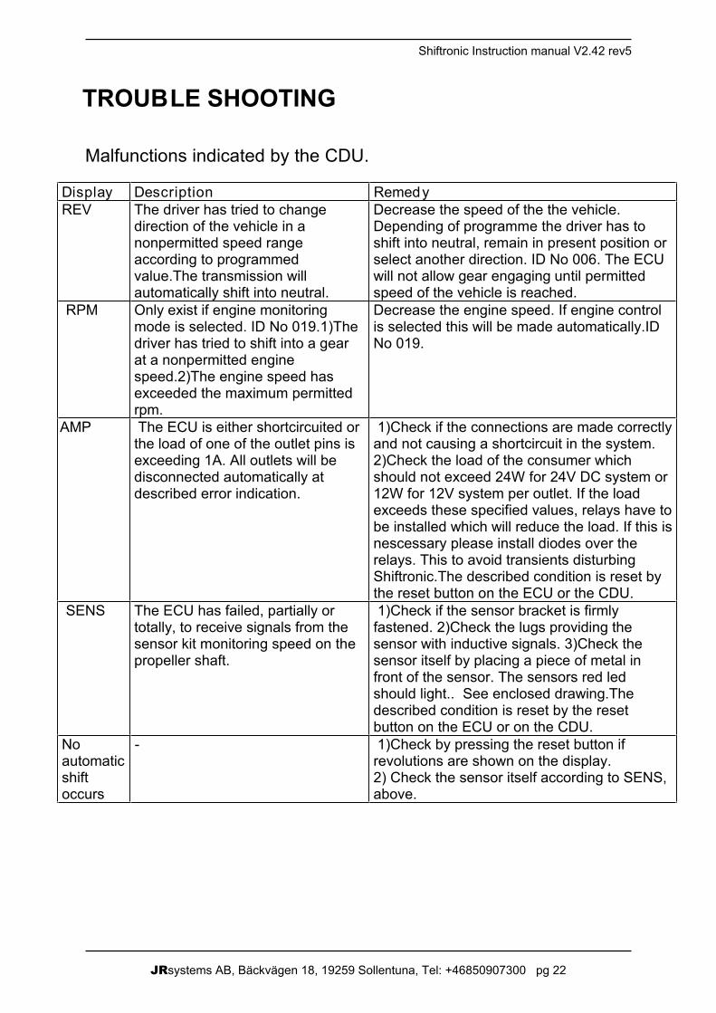
TROUBLE SHOOTING
Malfunctions indicated by the CDU.
Display Description RemedyREV The driver has tried to change
direction of the vehicle in anonpermitted speed rangeaccording to programmedvalue.The transmission willautomatically shift into neutral.
Decrease the speed of the the vehicle.Depending of programme the driver has toshift into neutral, remain in present position orselect another direction. ID No 006. The ECUwill not allow gear engaging until permittedspeed of the vehicle is reached.
RPM Only exist if engine monitoringmode is selected. ID No 019.1)Thedriver has tried to shift into a gearat a nonpermitted enginespeed.2)The engine speed hasexceeded the maximum permittedrpm.
Decrease the engine speed. If engine controlis selected this will be made automatically.IDNo 019.
AMP The ECU is either shortcircuited orthe load of one of the outlet pins isexceeding 1A. All outlets will bedisconnected automatically atdescribed error indication.
1)Check if the connections are made correctlyand not causing a shortcircuit in the system.2)Check the load of the consumer whichshould not exceed 24W for 24V DC system or12W for 12V system per outlet. If the loadexceeds these specified values, relays have tobe installed which will reduce the load. If this isnescessary please install diodes over therelays. This to avoid transients disturbingShiftronic.The described condition is reset bythe reset button on the ECU or the CDU.
SENS The ECU has failed, partially ortotally, to receive signals from thesensor kit monitoring speed on thepropeller shaft.
1)Check if the sensor bracket is firmlyfastened. 2)Check the lugs providing thesensor with inductive signals. 3)Check thesensor itself by placing a piece of metal infront of the sensor. The sensors red ledshould light.. See enclosed drawing.Thedescribed condition is reset by the resetbutton on the ECU or on the CDU.
Noautomaticshiftoccurs
- 1)Check by pressing the reset button ifrevolutions are shown on the display.2) Check the sensor itself according to SENS,above.
JRsystems AB, Bäckvägen 18, 19259 Sollentuna, Tel: +46850907300 pg 23

JRsystems AB, Bäckvägen 18, 19259 Sollentuna, Tel: +46850907300 pg 24

JRsystems AB, Bäckvägen 18, 19259 Sollentuna, Tel: +46850907300 pg 25
Important information, control/ecu units
· Check that the contents of the package are according to order confirmation and that the items are in goodcondition. Put in claim for incorrectness to supplier as soon as possible.
· Ensure a stable voltage source for optimal function. This is true about electric forklift trucks in particular. Supplyvoltage is 12V or 24V and should be secured with a fuse.
· Wiring harness between the control/ecu unit and the actuator should not be drawn together with the vehicle’spower cables or next to power connections on electric engines, radio transmitters, etc. Do not draw the controlunit harness in a closed circle, or through circles of other cables.
· Relays , coils, motors and other devices that can cause interference should be shielded with protective diodesor transient protection to prevent interference.
· Remove the vehicle voltage feed and ground connection from the vehicle if welding is necessary.
· Make sure that you protect the vehicle against static electricity whenever you work with it. Connect the chairarmrest to the vehicle chassis in order to lead away static electricity caused by friction between the driver andthe chair. Outgoing negative voltage from any DC/DC converter preferably be connected to the vehicle chassis.
· Do not open the control/ecu unit. Contact the service organisation if error occurs. If the control unit is opened ormodifies the JRsystems AB guarantee will expire. If the control unit modifies without JRsystems AB permissionwe disclaim our responsibility for the product.
· Do not expose the control/ecu unit to impacts. If someone drop the control unit or similar it should be sent tosupplier for control.
· Clean the control unit regularly with a damp rag with mild soap solution. The control unit cannot be soaked inwater, washed with high-pressure wash or have any other direct contact with water.
· The control unit is to be placed on an armrest to give the best ergonomic benefits. Choose an armrest withswitch in the joint of the chair. Supply voltage shall be disconnected when the armrest is raised.
· Turn off the control/ecu unit if error indication occurs and search for and correct the reason. If the problem is inthe control unit it should be sent to supplier for repair. Do never use a vehicle with a control unit with errorindication.
· Use shielded wires to sensors and connect the shield to the grounded box. Shielded wires should only haveone ground connection point.
· Use sealed connectors and gold plated pins/sockets for analogue signals.
· Include the control unit in the daily inspection of the vehicle before every start-up. Check that the control unit isin good condition especially the bellow, the lever and the buttons. If possible check the harness and theconnector. Contact the vehicle manufacturer for advice or service if you have any hesitations.
· Recommended wire areas: 1,5mm2 for supply voltage and ground. Other wires 0,6mm2. For EMMI: For use of5A (Dig out 1 and Dig out 2) 1,5mm2 is recommended.
· Only valid for EMMI: To secure the specified EMC requirements even in extreme circumstances, werecommend a ferrite placed on the harness as closed to the control unit as possible. Requirements of theferrite: Impedance 168 at 25Mh, 250 at 100 MHz, 300 at 300 MHz and 205 at 500Mhz. JRsystems AB partnumber 848782 or 848783.