Embed Size (px)
Citation preview
AT&T PRACTICE STANDARD SPCS
SECTION 320-235-100 Issue 1, December, 1940
AT&TCo Standard
PROGRAM SWITCHING EQUIPMENT FOR USE WITH
12 OR 14 TYPE PROGRAM AMPLIFIERS DESCRIPTION
.
CONTENTS PAGE
1. GENERAL
2. TRANSMISSION FEATURES
3· CIRCUIT AND EQUIPMENT FEATURES
~~~ General Switching Control Panel
(c Line Preselection and Switching Control Panel
'"l Cue Preselection Co~trol Panel
(E Program Monitor's ~quipment
~; Relay Equipment Permanent Line Connection
4. OPERATION
(A) Procedure (B) Manual· Switching - Non-Preselec-
tion (C) Switching With Line Preselection (D) Switching With Line and Cue
Preselection
5· OFFICE ARRANGEUEN.TS
6. BAY LAYOUTS
7. WIRING AND CABLING
1
3
6
6 8 8
10 11 11 11
12
12 12
15
16
18
19
20
8. DRAWINGS FOR REFERENCE 2]
1, GENERAL
1.01 This section describes the circuit ar-rangement, office equipment, wiring and
operation of apparatus for switching program transmission circuits. The switching equipment provides a means of grouping transmission lines in accordance with the requirements for setting up a broadcasting network for a particular program. This is done by connecting the lines involved to the branches of a bridge in the desired combination. These bridges may be of the C, D, F, or G type, but only one type of bridge may be associated with each switching panel. Circuits of reversible or non-reversible type using 12C, 14A, 14B or 14C program amplifiers can be accommodated by the switching panel.
1,02 For reversible control leads
are carried through and the direction
circuits, the reversing of the individual lines the switching equipment
of transmission o"f the
Copyright, 1940, by American TelephoPrinted in U. S
individual lines is determined in the normal manner by the reversal arrangements covered in other sections of these practices. A number of lines may be grouped in a number of combinations each combination carrying a separate program, The number of lines grouped in one combination is limited only by the number of branches on the bridge involved and the number of combinations by the number of separate bridges associated with the switching panel. The definition of a line in this section covers not only the circuits between the toll program offices but also monitoring branches and loops to broadcasting company studios.
1.03 Since the nature and quantity of switch-ing facilities required varies at dif
ferent program offices, three arrangements of switching equipment are available. Each of these arrangements is flexible in regard to the number of lines and bridges which may be provided. The equipment may be provided for direct· manual switching without line or cue preselection, for manual switching with line preselection, and for automatic switching with line and cue preselection.
1.04 Unfamiliar terms used in this se.ction are defined as follows:
(1)
(2)
(3J
(4)
(5)
A Manual Switch is a switch completed upon the simultaneous operation of the manual s"wi tch key and manual switch control unit by the attendant at the switching position.
An Automatic Switch is a switch completed under control of the program monitor 1 s cue key, when it is opera ted to satisfy the last of the preselected cues required for the switch of the line.
A Slow Switch is a switch made with the switching circuit conditioned to disconnect a line from its existing connection and allow three to five seconds to elapse before completing the new connection.
A Fast Switch is a switch made with the switching circuit conditioned to disconnect a line from its existing connection and immediately complete the new connection preselected,
Line Preselection is the advance selection of program lines to be combined
ne and Telegraph Comp&D¥ . A. Page 1
SECTION 320-235-100
P
(6)
(7)
(8)
(9)
in a program network, in anticipation of an impending switch, regardless of whether the indivi~ual lines are idle or in use at the time of the selection, and the conditioning of the switching circuit for rapid completion of the switch at the required time.
Cue Preselection is the advance selection and association with the preselected lines, of cues wh~ch will be received by program monitors over existing program networks, and the conditioning of the switching circuit fer automatic completion of the preselected switches upon the reception of the required cues.
The Cut Multifle is a horizontal row of· control un~ts in the line control panel associated with the individual program lines, the function of which is to actuate .the switching circuit to disconnect any line or lines from a program network and provide the necessary terminations for the idle status.
Cut Multiple Preselection is the advance selection of a line to be disconnected from a network and left idle and the conditioning of the switching circuit for rapid completion of the switch at the required time.
A Switching Multiple is a horizontal row of control units in the control panel each of which is associated with an indiviaual line and all of which are associated with individual branches of the same bridge.
1.05 The program switching cir~uit for manual switching without line or cue preselec
tion provides:
(1)
(2)
(3)
(4)
(5)
A means of connecting reversible or non-reversible program lines equipped with 12C, 14A, 14B, orl4C amplifiers, to any or.e of a number of bridges.
A means of automatically disconnecting the line from one bridge when it is switched to another bridge, thereby preventing connection of a line to more than one bridge at a time.
A means of disconnecting a line without making a new connection.
Prevention of accidental switching, by means of physically separated tandem keys which must be operated simultaneOusly to perform a switch,
Lamps to indicate idle, or to which nected.
whether a line is point it is con-
age 2
(6)
(7)
A means of connecting terminations to the input o.nd output of 12C, l.4A, and 14B program amplifiers and to bridge branches of l4C amplifiers which are idle.
A means of carrying through the control leads required for reversing.
1.06 The program switching circuit for manual switching with line preselection pro
vides:
(1) A means of preselecting reversible or non-reversible program 'lines equipped with 12C, 14A, l4B or 14C program amplifiers, to any one of a number of bridges, and of checking· the preselection made, in advance of the switching period for which the preselected network is held in ~eadiness.
(2) Simple 'and rapid correction of errors in the preselection of line or bridge.
(3) Switching on a slow or fast basis.
(4) For disconnecting lines, singly or in groups from a bridge and terminating them, without connecting to another bridge.
( 5) Lamps for indicating idle lines, preselected lines, switched lines, cues and any line affected by a fuse failure.
(6) For the completion of the switch manually upon receipt of a cue by the operator or upon receipt of a visual signal from a program monitor who has previously been informed, by means of a visual signal from the switching position, of the completion of. the preselection.
1.07 The program switching circuit arranged for automatic switching with line and
cue preselection provides the same facilities for line preselection as covered in Paragraph 1.06. In addition, the arrangement provides for the preselection of the cue or cues~ upon receipt of which each line is to be switched, and the transfer of control of the switch to keys· known as cue keys, provided at the program monitor's position. The switch is compieted automatically under remote control of the monitor's cue keys when the preselected cue or the last of a number of preselected cues is received over the existing programs.
1.08 Line patching jacks are alwa;)'s provided between the line equipment and the
switching equipment when l4C program amplifiers are utilized and may be provided on an optional basis when 12C, l4A or 14B program amplifiers are utilized. The purpose of these jacks is to provide a convenient means of
ISS 1. SECTION 320-235-100
p~tchin~ a line circuit to a group of switching equipment other than that with which it is normally associated. The patch is made with a four prong patch when 1.4C program amplifiers are used or whm l2C, l4A or 14B program amplifiers arranged for three cord amplifier patching; are used. When l2C program amplifiers arranged for four cord amplifier patching are used, the patch at the patching bay is made by means of an individual patching cord for each pair of jacks.
1.09 The equi nment is designed to mount on standard 19 inch relay rack of either
channel or I-bear:t construction. The equipment with the exception of the cue and cut multiple
LINE I
X X X X X X
X X X X X ~J
Tl Ti! T3 Rl R2 R3
c:::J
r~~ ~ ~ . 1
t•fFr• I• I• (L) OR 18) ~
MON.JKS.
~ XX
( - .,
+- ...._,. -,.y
............ -yyy
~- ,. I• (L) OR
r:> (8l c:::::l
XX ~
'
A
PATW
~ ~AA t.tULT. TO OT.. (8)RELS. AWITH SAt.tt
Fig. l·- Transmission Schematic of Switching Circ
relay unit (J68617 AJ), which is a shop wired and assembled unit is arranged on individual mounting plates or equivalent mounting strips and all equipment is mounted on the bay, wired and tested by the installer.
2. TRANSMISSION FEATURES
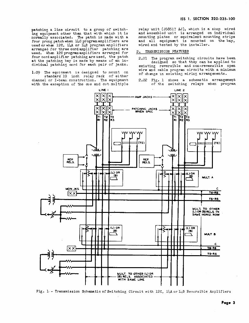
2,01 The program switching circuits have been designed so that they can be applied to
existing reversible and non-reversible open wire and cable program circuits with a minimum of change 1n existin:; wirin~ arrangements.
2,02 Fig. l of the
shows a schematic arrangeme~t switching relays when program
t.tf? JACKS
CHING JACKS HEN SPEC
(TEl
LINE 2
X X X X X X
X X X X X X
Tl T2 T3 Rl R2 R3
~ (TE)
~IQ.,-<=I
~I "'\.A~
s. :;.
l•t}r• I• I• (LlOR (8)
c:::l t.IULT. A
c TS-R6
T&·RS
t.tUL T. TO OTHER CLlOA(B)RtLS. IN SAME HORIZ. ROW
,_ .<. ,. I• (Ll OR ·:s. (8) c:::\. t.tut..T. 8
c T•Ra
TS-RS
HER ILl OR SSOCIATED LINt
uit with 12C, ll..,A or lL1B Reversible .Ar:!plifiers
Page 3

SECTION 320-235-100
P
switching is applied to reversible program circuits equipped with 12C, 14A or l4B amplifiers. On existing cable circuits the 12C amplifier associated with C, D or F type bridges may be involved. Referring to Fig. 1, it will be noted that three separate T and R leads are shown connected to the patching or line jacks as required. The T2 and ~ leads shown on Fig. 1 are wired only in those cases where 12C amplifiers are used and arranged for monitoring
LINE l
t-------AMP
Tl Rl
<L>OR (8)
D <UOR (8)
PATCH
MUL T. TO ORELS. ASSO
SAM
Fig. 2 - Transmission Schema tic of Switching Circui
age 4
winding bridging with four cord patching arrangements and F type bridges. &inoe the F type bridge has a repeating coil input, these additional leads and relay contacts are provided in the swi+.ching circuits to provide for the proper input connection when the associated reversible 12C amplifiers are transmitting into the bridge. The switching circuits have been arranged to operate with the standard remotely controlled reversing
LINE 2
. JACKS ------4~
ING JACKS WHEN SPEC.
D (T[)
THER CL) OR (B) CIATED WITH E LINE
Tl Rl
0 (L) OR
(8l
~ (Ll OR
(8}
0. (TE)
MULT. A
MULT. B
t with 12C, 14A or l4B Non-Reversible Amplifiers
ISS 1 I SECTION 320-235-100
arrangerr.ents which are described in other information.
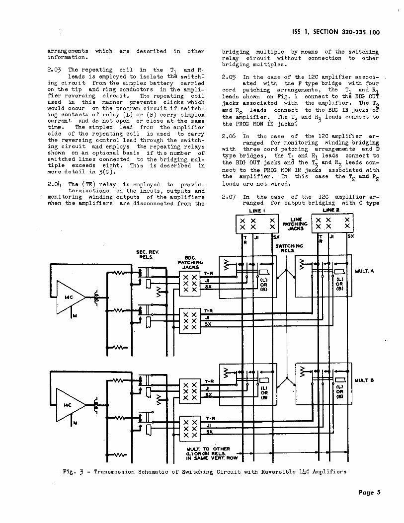
2.03 The repeating coil in the T1 and R1 leads is employed to isolate the switch
ing cirrui t from the simplex battery carried on the tip and ring conductors in the amplifier reversing circuit. The repeating coil used in this manner prevents clicks which would occur on the program circuit if switching contacts of relay (L) or (B) carry simplex current and do not open or close at the same time. The simplex lead from the amplifier side of the repeating coil is used to carry the reversing control lead through the switching circuit ru1d employs the repeating relays shown on an optional basis if ~,e number of switched lines connected to the bridging multiple exceeds eight. This is described in more detail in 3(G).
2.04 The (TE) relay is employed to provide terminations on the inputs, outputs and
monitoring winding outputs of the amplifiers when the amplifiers are disconnected from the
SEC. REV. R!LS. BOG.
PATCHING .JACKS
... AA ill T-R .,. XX
WQ}-.II
~~ XX sx
.. ~ r- XX
L1w ~ "' • II T·R XX
~[} XX .II sx
""" XX
...AAA ......
'"' {ll ..... T·R
~0}-xx
Jl
-~ XX sx
~ r- XX
L1: ~ IT .. T•R XX
~0 XX .II
,.. XX sx
MULT. TO OTH.A AA (L)0R(8) REL"YYY"
IN SAUE· VERT
Fig. 3 - Transmission Schematic of Switching C
brid~ing multiple by means of the switchin~ relay circuit without connection to other bridging multiples.
2.05 In the case of the 12C runplifier associ-a ted with the F type bridge with four
cord patching arrangements, the T1 and R1 leads shown on Fig. 1 connect to the BDG OUT jacks associated with the amplifier. The T2 and R2 leads connect to the BDG IN jacks or the amplifier.. The T
3 and R
3 leads connect to
the PROG MON IN jacks •
2.o6 'In the case of the 12C amplifier ar-ranged for monitoring winding bridging
with three cord patching arrangements and D type bridges, the T1 and R1 leads connect to the BDG OUT jacks and the T and R) leads connect to the PROG MON IN jacfs associated with the amplifier. In this case the T2 and ~ leads are not wired.
2.07 In the case of the 12C amplifier arranged for output bridging with C type
LIN£ I UNl2
I~ X XJ UNE X X X X X PA~G X .X X
'T .II SX T .II SX R
SWITCHING It
RELS.
~ ,. I• - ... 1-5 D. v "'\ D
(L) (L)
UULT.A
OR OR (8) (B)
~ I• 1- ~~· , .. 1-S" 1
CJ c:::l V" (LI <U OR OR (!W (II)
MULT. B
ER S . . ROW
ircuit with Reversible l4C Amplifiers
Page 5
SECTION 320-235-100
bridges, the T1 and R1 leads connect to th6 BDG OUT jacks. The T3 and R3 leads connect to the MON BDG jacks. Here again the T2 and R2 leads are not wired.
2.08 In reversible open wire circuits employ-ing 14A or 14B amplifiers and arranged
for program switching, only C type bridges are employed, In those cases the T1 and R1 leads connect to the E L (east line) jacks. The r
3 and R~ leads connect to the AMP MON SW jacks, The T2 and ~ leads shown in Fig. 1 are not wired when the above arrangements are employed.
2.09 Fig. 2 ~hows the transmission schematic of the switching relays when connected
to cable cir·cui ts equipped with non-reversible 12C amplifiers or to non-reversible open wire program circuits equipped with 14A or 14B amplifiers.
2.10 In the case of non-reversible circuits, only the output lines of the bridging
mu1tiples are switched. The input lines are generally permanently connected to the bridge and the output lines switched to the various multiples as desired. In the case of nonreversible lines, only the T1 and R
1 leads are
involved and when the l2C amplif1er is employed with either monitoring winding or output bridging arrangements, the T1 and R1 leads connect to the BDJ OUT jacks.
2.11 On non-reversible open wire program cir-cuits with 14A or 14B amplifiers an~ C
type bridges, the T1 and R1 leads connect to the E L (east line) jacks. When the F type bridge is associated with the 14A or 14B on non-reversible open wire program circuits, the T1 and R1 leads connect to the BDG OUT jacks.
2.12 Since no reversing control current is involved on non-reversible cable and
open wire circuits, isolating repeating coils between the amplifiers and the bridge legs are not required as in the case of reversibl~ program circuits shown in Fig. 1.
2.13 Fig. 3 shows the transmission ·circuit arrangement employed when the program
switching system is applied to reversible open wire and cable program circuits equipped with the 14C amplifier and associated G type bridge. The operation of the (L) or (B) switching relay connects the T and R leads of the line to a leg of the G type bridge. It also connects the J 1 and SX leadq from the reversing control circuit associated with the reversible line to the G type bridge. The J 1 lead connects to the winding of the secondary reversing relay associated with a particular leg of the bridge and the SX lead carries reversing control current to the other SX leads associated with the various legs of the bridge. 2.14 The bridge patching jacks are those di-
rectly associated with the reversible G
Page 6
type bridge and the T and R leads connect directly to the BDG SW jacks. The line patching jacks are added when the switching system is applied so as to provide full flexibility in the association of the switching relays with different program lines or multiples ~s required, Here the T and R leads 0onneot directly to the L SW jacks. The.primary reversing and control circuits associated with each reversible line connected to the G type bridge provide for the cOnnection of the program lines to the input of the 14C amplifier or output of the G type bridge as required and are described in other standard information.
2.15 Fig. 4 shows a schematic arrangement of the transmission circuit associa~ed with
the switching system when applied to nonreversible open wire or cable program circuits equipped with the l4C amplifier and associated G type bridge. Here again only the output lines of the G type bridge are switched by
·means of the switching system and the. input lines are generally permanently connected to the inputs of the 14C amplifier. The T and R leads on the bridge side of the switching relays connect directly to the BDG SW jacks and the T and R leads on the line side of the switching relays connect directly to the L SW jacks in the same manner as shown in Fig, 3 for reversible cable and open wire program circuits when associated with the 14C amplifier and reversible G type bridge.
3. CIRCUIT AND EQUIPMENT FEATURES
(A) General
3.01 The equi~nent required for switching program circuits can in general be
separated into two parts according to-its functional operation, namely the control panel which sets up the switChes and the relay equipment which performs the switching operations. The control panel is comprised of. control units, keys and lamps required by the swi tchin~ attendant fb r the performance of line and cue preselection and m~~ual switching functions. The relay equipment comprises the relays, resistances and coils necessary for the proper functioning of the circuit.
3.02 Circuit and equipment details of the switohin~ and preselection circuits
are covered on SD-55054-0l, SD-64781-01) SD-64782-01, SD-64783-01, ED-61705-01 and ED-61699-01 (not attached),
3.03 The control unit, which has been coded 36A,' is a compact combination key and
lamp unit, which intimately associates supervisory si~nals with keys. Fig. 5 shows the general features of this control unit. It consists of two lamp sockets accommodating K type lamps and a non-locking push type key havin~ two sets of make contacts, all assembled
0
on a frame in a vertical line. The key is centrally located between the lamp sockets
ISS 1, SECTlON 320-235-100
LINE LINE 2
T R
LINE PATCHING
JACKS
SWITCHING RELS.
~ (U OR
<B>
D (L) OR
(8)
. ~UL T. TO OTHER (L) OR CB) RELS.
T IN SA~E LINE R
T R
~ (L) OR
(B)
~ (L) OR
(8)
T R
MULT. A
MULT. B
Fig. 4- Transmission Schematic ofSwitchin:>; Circuit with Non-Reversible 14.C Amplifier
I
LAMP ___ / SOCKET
LAMP CAP$
PLUNGER
Fig. 5 - No. 36A Control Unit
and its operating plunger is rigidly connected to a plate in which the lamp caps are located. The lamp cap assembly acts as the operating button for the key. The operating face of the control unit is rectangular in shape, approximately 5/8" in width and 1-1/4" in height. It is aTranged for mounting on a special mountirg equivalent to a 1-3/4" x 19" mounting plate which has a capacity for 20 control uni~s. Where a control unit is referred to in the following paragraphs it is understood to be the 36A control unit,
3.04 The control panels are not shop wired units, but are composed of individual
mounting plates and control units, assembled on the bay to form a compact unit for operating purposes. The control panel may be assembled as a line panel or as a cue panel. The control panels in a'particular office may consist of a line panel alone or a line panel and a cue panel. When the line panel only is provided it may be assembled for manual switching
Page 7
SECTION 320-235-100
·
only or for line preselection and manual switchin~. When both the line and cue panels are provided they are arranged for preselection of both line and cue and both automatic and manual swi tchin~ to meet the ,varied switching requirements. Typical arrangements for the three conditions are shown in Figs. 6, 7 and 8.
(B) Control Panel for Switching Without Preselection
3·05 Fig. 6 shows a typical arrangement of the line,control panel where switching,
without line or cue preselection is required and provides a capacity in various sizes, The number of lines in each control panel is limited to 18 per bay and the number of switching multiples, which crorrespond to the number of bridges, is limited only by the available space on the bay. The control units are arranged in vertical and horizontal rows, the vertical rows associated with the lines and the horizontal rows, which compose the svri tching multiple, associated with the bridges, Both. the upper and lower lamp sockets. of these control units are equipped with red lamp caps but onl;r the upper socket is equipped wi tb a lamp which is lighted when a line is connected to the associated bridge. Number designations are shown on the lamp caps, those on the upper lanp caps corresponding to the line number and those on the lower la!np caps corresponding, to the switching multiple number. To the left of the control units in the first multiple row is a master switch (MAS SW) key which is of the non-locking push button trpe. This key is arranged so that simultaneous operation of the n.aster switch key and an individual control unit is required to perform a switch. This is a safety
I
® ()--LA1o4P
Ea [gi=LON£ NO. Q KEY SW I MULT. NO.
~ ~ 2
~ ~ 3
~DESOO STRIP
Fig. 6- Typical Layout ofLine Control Panel
Page 8
feature to prevent false switching by the accidental operation of a single key. Idle line lamps, associated with each line, are located at the top of the control panel in a horizontal row. These larr,ps are equipped with green lamp caps and are lighted when the associated program line is not in use. Below the control units is a row of designation strips, one strip associated with each line.
for Swi tchi " With Line
3.o6 Fig. 7 shows a typical arrangement of the line control panel for line prese
lection and switching either manually without cue preselection or automatically with cue preselection. The capacity of this control panel is limited to 17 lines per bay when cue preselection is not used and to 18 lines per bay when cue preselection is used. The number of switching multiples, which corresponds to number of bridges, is limited only by the available space on the bay.
3.07 The line control units are arranged in vertical and horizontal rows, the verti
cal rows associated with the lines and the horizontal rows, which compose the switching multiples, are associ a ted with the bridges. On these control units the upper lamp equipped with a white ·lamp cap is li[;hted when the line is preselected and is extin~uished when the switch is completed. The lower lamp equipped with a red lamp cap, is lighted when the switch is completed and remains li~hted as long as the connection is maintained. Number designations are shown on the lamp caps, those on the upper lamp caps corresponding to the line number and those on the lower lamp caps correspondinr.; to the switching multiple number.
18
0 @
CONTROL UNOT ---[:J CD Er
~ Er
~ 3 rf
D Arranged for Direct l"'Anual Switching
ISS 1 I SECTION 320-235-100
8 Q--LAMP 0 8 I 18
[]--DE"G STROP D ~~~LINE NO. ~~~t! 0 RL LT
R~ CONTROL UNIT . CUE 0 I 0 I MULT. NO.
ro~~ 0 ® ~~~~ Soz
~~~ r=- .---
~r! ® IIULT
LAMP 0 @ c~ ......_ I--
~f'LM'0 ~ ~ r--
II\ 0 ~ 0 . KEY KEY '-" 0
LT RLS 0 CUE MO I-- I-- - I-- ...__
~~-~ "" ~ ~
© - Q--KEY 0 © -I 18
Fig. 7 - Typical Layout of Line Control Panel Arranged for Preselection
In the right and left end positions of each multiple row are located control units designated (RLS), the upper and lower lamp sockets of which are equipped with green lamp caps.. The upper lamp sockets only are equipped with lamps, which are lighted when no lines .s.re connected to the brldge associated with the switching multiple. The simultaneous opera ti~n of the two (RLS) keys in a switching multiple will release all lines connected to or preselected to the bridge associated with the multiple and transfer the connected lines to the cut multiple. This simultaneous operation of the two keys is a safety feature to prevent release of a muitiple by the accidental operation of a sin~le key.
3.08 When this panel is used without cue pre-selection a multiple cue lamp (MULT CUE)
is provided to indicate when the cue for a manual switch has been received from a program monitor, and serves as a signal to complete the switch. It is equipped with a red lamp cap and is located in the position of each switchin~ multiple which would normally
be equipped with the line control unit for line 18. When the panel is used with cue preselection the multiple cue lamps are omitted affording space for one additional line in the switching mul~iples.
3·09 Below the line control units are located the cut multiple control units arranged
in a horizontal row with one control unit associated with each line. In these control units, the upper lamp, equipped with a white lamp cap, is lighted when the line is preselected and is extinguished when the switch is corr.pleted. The lower lamp equipped with a red lamp cap is lighted when the switch is completed and remains lighted as long as the line is cunnected to the cut multiple. The master cue lamp (MAS CUE) equipped with a red lamp cap is located in the position of the cut multiple which would normally be equipped with the cut multiple control unit for line 18. To the right of this lamp 5s located the master cue key (MO), which is a locking turn button type key. The operation of this key lights the master cue lamp and transmits a signal to
Page 9
SECTION 320-235-100
P
the program monitor indicating that the preselection for the ensuing program is completed, When the panel is used with cue preselection the master cue lamR· and key are omitted affording space for an additional line in the cut multiple~
3.10 Alarm lamps (ALM) equipped with red lamp caps are located at the top of the control
panel in a horizontal row, one lamp being associated with each line. These lamps are arranged to light upon failure of the fuses which supply battery tc the switching circuit for the associated line. They remain lighted, even though the fuses are replaced, until the alarm release key (ALM RLS) is opera ted, The alarm release key is a nonlocking push button type key located to the left of the cut multiple control units,
3.11 Below the cut multip~e control units are located the manual switch control units,
one associated with each line. The upper and lowor lamp sockets of these control units are equipped with white lamp caps. The upper socket only is equipped with a lamp which is lighted when the line is preselected, This lamp acts as a line pilot, indicating a preselection of the associated line and provides a check on a burned out preselection· lamp in
[}-----DE$00. STROP
:!]Fc;l~ ~~
LINE NOS.
CONTROL UNIT MULT. NOS
lwi:n~LAMP ~~
@ ()--LAMP
Fig. 8 - Typical Layout o
age 10
. the swi tchin~ multiple which should be lighted at the same time. The keys of these control units are supplied with ground through contacts of the master switch (MAS SW) key which is of the non-locking push button type and is located to the left of the manual switch control units. When a manual switch control unit is operated simultaneously with the master switch key the connection of the associated line to the bridge or cut multiple for which it has been preselected is completed. Here again the simultaneous operation of two keys reduces the probability of false operation due to accidental operation of a sin~le key.
3 •. 12 At the bottom of the control panel are the timing keys (SLOW-FAST) which con
trol whether the line is to be switched on a slow 0r fast oasis. The designation strips, which perform the same function as those cov~red in Paragraph· 3.05, are located near the top of the control panel be,tween the alarm lamps and the line control units.
(D) Control Panel For Cue Preselection
3.13 Fig. 8 shows a typical arrangement of the cue control panel for cue preselection.
D
--KEY-§]Ef
o@ ••
f Cue Control Panel
·
ISS 1 I SECTION 320-235-100
·
The capaoi ty of this control panel is limited to 18 lines per bay, but the number of switching multiples, which corresponds to the number of bridges, is limited only by the available space on the bay. The designation strips in this arrangement are located at the top of the panel with the cue control units grouped below them in the same manner as the line control units covered in Paragraph 3.07. The cue control units are equipped with white lamp caps in both upper and lower positions but only the upper lamp socket is equipped with a lamp. They perform the same func tiona in preselecting cues as the line control units perfor-m in preselecting lines, The multiple cue lamps are omitted from the l'ine control panel when cue preselection is furnished and are located in the cue control panel to the left of the cue control units.
~.14 The master release keys (MR) and (MRl) and the master cue control unit (MON)
are located. in the extreme right position of the last three multiple rows. The function of the master release keys, which are of the rion-lookin5 push button type, is the restoration of the cue preselection oirc,li t to normal after all preselected lines have been switched and all preselected cues satisfied, The master cue control unit. (MON) is equipped with red lamp caps in the upper and lower positions but only the upper lamp socket is equipped with a lamp to function as a master cue indication. The key and lamp combination perform the same function as covered for the master cue lamp and key in Paragraph 3 .09, and in addition extends control of the switch panel to the monitor's cue keys.
3.15 At the bottom of the control panel are the wait cue lamps (WAIT CUE) which are
equipped with white lamp caps and are lighted when cue preseleotions are made on the assooia ted line, They act as vertical row pilots and provide a check on burned out cue preselection lamps associated with the multiple rows which should be lighted at the same time.
(E) Program Monitor's Equipment
~.16 The equipment appearing before each pro-gram monitor consists of a ~ush button
or lever type key (CUE), two lamps l CUE READY) and (CUE SENT) , and pa tohing jacks when required. The (CUE READY) lamp, equipped with a white lamp cap is lighted, upon the operation of the master cue key in the control panel, when all preseleotions have been completed. It is extinguished by the operation of the monitor's (CUE) key, which also lights the (CUE SENT) lamp equipped with a red lamp cap. These jacks, keysand lamps are located in jack fields, or in other convenient locations at special monitoring positions as specified.
(F) Relay Equipment
~.17 The relay, resistance, and coil equipment, with the exception of the cue and
out multiple relay unit (J68617AJ) 1s arrangetl on. individual mounting plates. Each relay· mounting plate and coil mounting is arranged for eight circuits, and each resistance mounting plate is arranged for 16 circuits. The individual mounting plates are grouped on the bay to facilitate wiring and cabling. When a switching or line preselection relay in a multiple for any line is omitted, a 203 type terminal strip is substituted for terminating the multiple widng to adjacent relays.
3.18 With lines utilizing 12C, l4A or l4E program amplifiers, a repeating coil is
furnished in the transmission leads between the amplifier and switching equipment to isolate the transmission contacts of the awi tohing relay from the reversing control current. A lead from the midpoint of the coil carries the reversing control current through the switching circuit and provides the cue connection when the cue is to be obtained from the bridging multiple. Where more than eight lines are arranged for connection to the same bridge, repeating relays are required in the lead carrying the reversing control current. With lines utilizing 14C program amplifiers the repeating coil and repeating relays are not required, since the reversing control current is carried through the switching circuit in separate leads from the line to the amplifier.
3.19 When 12C, l4A or l4E amplifiers are used, prov1s1on is made for terminating
the input, output and monitoring output when the amplifier is disconnected from the bridge.· The terminating resistances are added to or removed from the circuit under control of the ·switching relays. With l4C program amplifiers this arrangement is unnecessary, since the bridge circuit provides the necessary terminations. • ~.20 f.he 24-volt b~ttery supply for operating
relays and lamps is furnished through a filter located at the fuse board to eliminate the possibility of noise entering the program transmission leads from this source. The battery supply to the relays and lamps associated with each line is supplied from non-ad,iacent parallel fuses to reduce the possibility of program interruptions due to fuse failure .•
~.21 The J68617AJ cue and out multiple relay unit provides a completely wired unit
on a 15-3/4" panel containing the alarm relays and relays for controlling preselection to the out multiple, slow and fast switching, and operation of the switch under manual or automatic control, for 5 circuits.
(G) PermanEil t Line Connection
~.22 A. program line may be permanently connected to a bridge which also aooommo.
datea swi tohed linea. Lines using l4c reversible
Page 11
SECTION 320-235-1 00
or non-reversible program amplifiers or 12C, l4A or l4B non-reversible program amplifiers are permanently connected to ·the bridge in the normal manner for non-switched lines and have no connection with the switching circuit. Lines using 12C, l4A or l4B reversible amplifiers, when permanently connected to the bridge, require a connection for carryin5 the reversing control current between the switched and permanently connected lines. Two arrangements are provided, their use depending on the number of .lines permanently connected to the same bridge.
3.23 When 5 or less lines, permanently con-nected to the same bz·idg;e, are required,
a resistancg simplex across the bridge, and a set of relays for repeatin~ the reversin~ control current into the simplex, arc provided to carry the reversin; control current through the bridge to the perma_'1en tly connected lines. In this case the cue connection is obtaial3d frol:'. the repeating relays when the C).le is to ~e obtained from the bridging multiple. A 0.6 db pad is provided in the transmission leads between the amplifier and its bridge outlet for each permanently connected line, to insert a loss equivalent to that of the repeating coils in the switched lines.
3·24 V..'hen more than 5 lines, permanently con-nected to the same bridge are required,
the resistance simplex with its associated repeatin~ relays, is omitted and a repeating coil is substituted for the 0,6 db pad in the transmission leads of each line permanently connected to the bridge, to perform the same function covered in Paragraph 3,18 for switched lines. Repeating relays are required as covered in Paragraph 3.18 when the combined number of switched lines and lines permanently connected to the bridge through repeating coils, exceeds 8,
4, OPERATION
(A) Procedure
4.01 In direct manual switchin~ the operation is straightforward. In the case of line
or cue preselection arrangements, however, a number of convenient operatin~ features are provided on the switching equipment, and to make more effective use of them there is a ·preferable sequence of operation. Since these featv.res and sequence may not be readily apparent from the detailed descrip~ion of equipment and circuit features, the following brief outline serves to give a general overall picture of program switching. This will be fol-
. lowed by a more detailed discussion of the operation of the equipment,
4,02 Asstuning; the operation starts at a time before the initial broadcasting period
for the day, or immediately after switches have been completed for one program period, the operative steps with their particular features are ·listed in order.
Page 12
(1)
(2)
(3)
(4)
(5)
(6)
(7)
(8)
(9)
Preselect all switches and cues required for the next program period. This may be done by the preselection of the required line followed immediately by the preselection of the required cue or cues, applying to that line. However, if desired the preselection of all lines may be completed before making any cue preselections.
Visually check and correct all line and cue preselections.
Check the position of the SLOW-FAST switch keys. Ordinarily the keys associated with each line will normally remain opera ted to either the SLOW or FAST position and it should not be necessary to check their pos1t1ons before each switching perio~ unless a change is called for on the pro~ram switching order.
Operate the master cue lMAS CUE) key, This should be postp0ned until the shortest convenient time before the first switching cue is expected. The operation of the master cue key energizes the CUE keys at all monitor positions for which cues have been preselected and with these CUE keys energized much in advance of the switchin3 period, the possibility of an unwante~ switch due to accidental operation of a monitor's CUE key is increased,
Monitor's CUE keys are operated upon receipt of predetermined cues. When all preselected cues for each line are received the line will be switched.
Visually check the line and cue preselection control panels to see that all switches have been completed. Any white lamp li~ted on either of the panels indicates an incompleted switch.
Complete, manually any incomplete switch remaining due to failure of the switching equipment.
If practicable determine caus·e of failure to complete switch, and extinguish lighted cue preselec~ion lamps.
Restore the cue preselection panel and lamps at monitor's positions to normal.
(10) Make extra switches at any time between regular switching periods,
(B) Manual Switching Non-Preselection
4.03 The line control panel arrangement for program s~itching on a manual basis
ISS 1 ,· SECTION 320-235-1 00
(A) ~'':" -R~ ·:f-+1 tO • ...__ ___ ....... _
~----------~~--~~
I
CB)
I
TO CORRES. TERMS OF OTHER (A) & (B) RELS. ASSOCIATED WITH SAME LlNE
( OPR) ' RLS
TO ALL OPR RLS) CONT. UNITS
Fig. 9 - Switching Control Circuit Without Preselection 12C, l4A or l4B Program Amplifiers
without preselection is covered in Fig. 6. The swi-tching control circu·i t arrangements for 12C, L4A and l4B prograw. amplifiers are covered in Fig. 9 and for l4C program amplifiers in Fig. 10. Although the control circuits differ from each other in some respects, the operation of the control panel is the same' in all cases.
4,04 In order to perform a switching opera-tion, the line control unit associated
with the line and bridge to be connected, is operated simultaneously with the master switch (MAS SW) key. The operation of the control
r;:~?) (t~i)
(B) ..-....... -e-..1\/v<tJ\1\p,....l rl~n-o CA) ·~-
THRU CONTACTS OF CB) RELS. IN OTHER MULTS. --: ASSOCIATED WITHJ• SAME LINE
I
I
TO CORRES. TERMOF OTHER CA)RELASSOCIATED WITH
SAME LIIIF'
Fig. 10- Switching Control Circuit Without P
unit closes the contacts of its key (OPR RLS) and connects ground from the simultaneously operated (MAS SW) key to the swiuching relays, causing; -them to operate and complete the switch.
4,05 Before the switching relay operated, the line may have been idle or connected to
another bridge. Assuming the line was idle, the operation of the switching relays will remove terminations, connect the line to a bridge, extinguish the green (IDLE LI1~) lamp and light the red lamp in the control unit to indicate the switch has been made. Assuming
---+1 ~*~9~
. S.
I
....__.--It-. ~ .LA (~~$)
TO ALL COPR RLS) CONT. UNITS
reselention l4C Program Amplifiers
Page 13
SECTION 320-235-100
CT!I~ I
Tt Ojc EABF MULT. TO CORRES. ......,__+o-t......., ................. _ RELS. IN SAME VERT. ROW TO OTHER
RELS.j ::M£ MULT.
r---
~
10 OTHER LAMPS IN SAME MULT.
IIMI _n
MULT. (L) r
--j•!•l• ~, .. , .. , ffic~TI
=!="
l ~~·~ 4 I L r '
~ ~ w '
~~I ~~-~ CAl If~ 1
~ ~) IOL£ t_G-I 181 ""-- ,
t---p_ fu ~ ~f_:j ~0 ~ -f1•1-6 . . . . . ----~---..... ~~·~~++~ ~~~+------------------------------.
TO CUE {~' PR£SELECTION CU CKT. .----
--
Page 14
tLP) • ' L-~~~~--------------------~~-~-.. -a-.-l•hL-~--, ~~~ ",!, " II .IT !
'"' _Jj·l~or (CO)Ibr * II~ ........... --:--~ IT - ~~ -- J rr.l 1., (CU) ~ u:; n .._ ~__j I~ I ~ ~ j:f:n ~~l! II l ~ ::::tcUP~-t-,~~LJ'l.i (J) y.r I
I r---lh- ~N~ '------1----t--·'-u! ~ I .ru- ·~ r---- ... ___ . ---------
J ;=:~r-· +---- •
..! ~OW) L
AST j_ SW K£YS
f
·>--
------------
I
Fig, ll - Switching Control Cirauit with Line Preselection
ISS 1 I SECTION 320-235-100
the line was connected to another bridge the operation of the switching relays will release the existing connection and extinguish the red lamp in its associated control unit. It will also connect the line to the bridge associated wi~ the control unit operated and light the red lamp in this control unit to indicate the switch has been made.
4.o6 A line may be disconnected from a bridge without connecting it to another bridge
by simultaneously operating the'{MAS SW) key and the control unit associ a ted with the connected line and bridge. The operation of the {MAS SW) key and control unit will release the switching relays, which release the line from the bridge, connect terminations to the bridge leg or amplifier as required, extinguish the red lamp in the control unit and 1 igh t the green (IDLE LINE) lamp, indicating the line is not connected to any multiple.
(c) Switching With Line Preselection switching)
{Manual
4.07 The line control panel arrangement for program switching with line preselection
is covered in Fig. 7. - Tl1e switching control cir_cui t for 12C, 14A, 14B, and l4C program amplifiers is covered in Fig. 11. Although the control circuit differs slightly for the different type program amplifiers, the operation of the control panel is the same in all cases.
4.08 A program network is·. preselected by momentarily operating the line control
units associated with the lines and multiple ·to be connected. At the time of preselection the lines may be either idle or connected to a bridge. The idle condition is indicated by the associated red lamp being lighted in the cut multiple control unit. The line connected to a bridge ie indicated by the associated red lamp being lighted in the line control unit appearing in the multiple to which the line is connected. These red lamps indicating the condition of the line are not affected by the preselection and remain lighted.
~·09 Referring to Fig. 11, the operation of the line control unit in the multiple
closes the contacts of its key {OPR RLS) which operates the preselec~ion relays (A) and {B) associated with the line to be switched. The operated preselection relays perform the following functions.
(1) Condition the associated switching relay {L) for operation through contacts of relay (A) at such time as the master switch key (MAS sw) and the manual switch control unit (MAN SW) are operated simultaneously.
(2) Light the white lamp in the line control unit to indicate that the preselection has been made.
(3)
(4)
Light a white lamp {ROW PILOT) in the (MAN SW) control unit indicating the line has been preselected and providing a check on the white lamp in the line control unit.
Extinguish the green lamps (IDLE MULT) in the release con·trol units (RLS) associated with the multiple. These lamps were lighted only if the multiple being preselected was idle.
4.10 If a wrong line has been preselected, the associated line control unit is re
operated, releasing the preselection relays; the proper line can then be selected by operating its line control unit. If a wron~ multiple has been preselected the operation of the line control unit associated with the correct multiplE' will release the incorrect preselection and make the correct preselection • •
CAUTION: Care should be taken to operate the control units to the fUll extent of- their travel, since a partial operation may not release the existing preselection even thou0h it does make the correct preselection. This condition is indica ted b two white
amps in line control units associated with the same line being li~ftted simultaneously. The condition should be corrected by operating the line control units associated with the lighted lamps and then making the correct preselection in the usual man.ner.
4.11 When a line required in the network be-ing preselected, is alrea~; connected to
the proper multiple, in the network used for the existing program, no operation is necessary as the connection will remain set up for the ensuing program.
4.12 When a line connected to an existing program is to be disconnected and remain
idle during the ensuing program period, it is preselected to the cut multiple by operating the associated cut multiple control unit. The operation of the cut multiple control unit, closes the contacts of its key {OPR RLS) which operates the cut multipl~ preselection relays associated with the line to be switched. The operation of the preselection relays lights the white lamp in the cut multiple control unit and the white lamp {ROW PILOT) in the associated (MAN sw) control unit, indicating the preselection.
4.13 After all preselections have been made a visual check should be made to ascertain
that all required preselections have been made correctly and that none have been overlooked. In this connection a white light in the line control unit associated with the proper line and multiple will indicate the preselecti~n made. Each line control unit associated with a line and multiple to be connected when the
Page 15
SECTION 320-235-1 QO
. ~
switch is made should have the white lamp lighted except in the case where the line is already connected to the multiple, which will show a lighted red lamp in the line control unit.
4.14 When all preselections have been made and checked the master cue key '(MO),
which is a locking key, is operated shortly before the switch is to take place. The operation of this key lights the red (MAST CUE) lamp at the switching panel and lights a white (CUE READY) lamp at the program monitor position, indica t'ing to the ·monitor that the preselections have been completed and are held in readiness for the switching period, The pro~ram monitor's position circuit is shown in ?ig. 12. When the switching period arrives, the monitor receives an audible cue over the existing pr?gram network and operates his (CUE) key which lights the red (MULT CUE) lampat the switching position. The attendant at the switching position then simultaneously operates the (MAS SW) key and the (MAN SW) control units associated with the lines to be svli tched, which perform the following functions.
sw. c.ot~ C.KT.{
8
OR TO CUE PRESELECTION
CKT. ~C.--o-:1LJ\
{ CUE ) READY
(Al.}
A} 'TO ANNUM. CKT. OR TO AUO. ALM. I.
DC OR WJ · PILOT LAMP CKr.
t
Fig. 13 - Fuse Alarm Circuit
Fig. 12- Program Monitor's Position Circuit
(l)· Release the switching relay associated with the line and multiple formerly connected.
(2) Operate the preselected switching relay which connects the preselected line and multiple.
(3) Release the preselection relays.
(4) Extinguish the white preselection and (ROW PILOT) lamps.
(5) Light a red l~p in the line control unit associated with the line and multiple connected, to indicate the SVIitch has been made.
After all cues have been received and the switch has been completed, the (MO) key is restored to normal, extinguishing the red (MAST CUE) and (MULT CUE) lamps at the switching panel and the white (CUE READY) lamp at the program monitor position. ·
Page 16
4.15 An entire program network, consi~ting of all the lines connected or preselected
to one multiple may be disconnected and the lines and multiple left idle by simultaneously operating the two (RLS) control units at the opposite ends of the row of line preselection control units associated with the multiple. The operation of these control units releases associated preselection and switching relays disconnecting all lines from the multiple and extinguishes the lighted (ROW PILOT), white preselection and red switch indicating lamps associated with the lines and multiple. It also .lights the green lamps (IDLE MULT) in the operated (RLS) control units, indicating the multiple is not connected to any line, and the red lamps associated with the lines in the cut multiple, indicating the line is disconnected from any switching multiple.
4.16 The (SLOW FAST) key associated with each line can be operated to cause the switch
to be made on a slow or fast basis. With the key operated to the slow position, a three to five second interval elapses between disconnecting the line from one multiple and connecting it to another. During this interval the red lamp in th~ associated cut multiple control unit is lighted. With the key operated to the fast position, the line is disconnected from one multiple and immediately connected to another and the red lamp in the associated cut multiple control unit flashes momentarily.
4.17 Snould the parallel fuses supplying bat-tery for the operation of a switching
circuit fail, the associated (ALM) lamp will light and remain lighted until the (ALM RLS) key is operated, even though the fuses have been replaced in the interim. This circuit is covered in Fi~. 13.
4.18
Cue Preselection
When program svri. tchlng with and cue presslection is ubed,
both line separate
ISS 1, SECTION 320-235-100
control panels are required - one for line presele.ction and one for cue preselection. These control panels are described in Part 3 of this section.
4.19 A program network is preselected in the line control panel and is checked and
corrected in the same manner as covered in Paragraphs 4.08 to 4.13 inclusive. This line control panel also provides facilities for disconnecting an entire multiple, for making a switch on a slow or fast basis and for fuse alarms as covered tn Paragraphs )_..l~i to 4.17, inclusive.
WL
cu
MULT. TO ALL CAl &(8) RELS.
IN SAME MULT.
LG
(D)
:r:
cu LC
MULT&(8)
B""--.--~'
TO SW. COHr. CKT TO PROG. WO
Fig. 14 - Cue Presel
4.20 Cue preselection for the prograt• network is accomplished in the cue control panel.
The cue preselection control circuit is covered in Fig. 14. When cue preselection is used, one or more> cues are required to be preselected for the switch of a preselected 1 ine. Those cue control units are opera ted which are common to the vertical row associated with the preselected line and the horizontal rov1s associated with the·program network over which the cue to the program monitor ~ill be received. The operation of each control unit closes the contacts of its key (OPR RLS) which operates the associated preselection relays. The operation of the preselection relays performs tl:c following functions:
. TO ALL (A) RELS.IN SAME VERT. ROW .
(MOJ
(Bl
( ROW) PILOT
I OPR) \RELS
( MULT) CUE
Ct.tR)
(t.tRI)
I
N. POlS.
ection Circuit
Page 17

SECTION 320-235-100
P
(1) Lights the white lamp in the asscciated cue control unit.
(2) Lights thewhite lamp (WAIT CUE) asscciated with the line to be switched.
(3) Prepares a path for the operation of the row cue relays, at such time as the master cue control unit (!'!0) is operated. These row cue relays are associated with. the vertical row of cue control units for each line.
A wrong cue preselection may be released by a second operation of the associated cue control unit.
4.21 After all cue preselections for the pre-selected network, have been made, a
visual check should be made to ascertain that all required cue preselections have been made correctly and that none hs.ve been overlooked·, In this connection a white light, in the cue control units common to the preselected line and the multiples over which the cuss are to be received by the program monitur, will indicate the cue preselection made.
4.22 When all cue preselections have been made, checked and corrected, the master
cue control unit (MO) is operated shortly before the switch is to take place. The operation of this control unit closes the contacts of its key which operates the master cue· relay (MO) to perform ~~e following functions:
(1) Lights the red lamp (MAS CUE) ir. the MO control unit.
(2) Operates the row cue relays over the previously. prepared paths through the preselection relays.
(3) Lights the white (CUE READY) lamp at each program monitor's position corresponding to the multiple on which a cue preselection has been made.
(4) Transfers control of the switching relays to the program monitor's (CUE) keys.
If for any reason a change in the cue preselections is required after the (MO) control unit has been operated, it is necessary to first· release the (MO) relay by the simultaneous operation of the master release keys (MR) and (tffil:)'inorder topreventapremature switch. After the chan~e in cue preselec.tions has been made, the(MO) control unit is again operated,
4.23 When the program awaited cue over
he operates his (CUE) this key:
monitor receives the the existing prcgran,
key. The operation of
( 1) Lights cia ted
a red (CUE SENT) with the (CUE)
lamp assokey at the
monitor position.
age 18
(2) Lights the red (MULT CUE) lamp associated with the multiple, on the cue
preselection panel, over which the cue was received.
(3) Releases the cue preselection relays associated with the multiple over
which the cue was received,
(4) Extinguishes the white lamp in the cue control units associated with the
multiple over which the cue was refleived.
When all the cue preselo~tion rel~s associated with a line are released, the white (WAIT CUE) lamp associated with the line is extinguished and the row cue relays associated with the line are released, performin~ the same functions in completin~ the switch as the sinul taneous operation of the (MAS SW) key anrl (MAN SW) control unit covered in Paragraph 4.14. 4.24 After the swi tc.~ has been co:::plated and
all white lamps extinguished the r:!aster release (~ffi) and (MRl) keys are simul~aneously operated momentarily to restore the cue pre:;election circuit to normal and extinguish the (MULT CUE) and (HASTER CUE) lamps at the cue preselection panel and the (CUE SEKT) lamps at the monitor position.
4.25 If any white lamps associated with the cue or line pr.eselection panels remain
lighted after a switch is completed it is an indication that all cues have not been received or that the switch has not been completed due to a trouble condition. The switching panel attendant can complete the switch mar!ually by simultaneously opera tin:; the (I1AN SW) and (MAS SW) keys on the line preselection and switching panel. The canse of the failure should then be checked, after ·~hich the operation of the (MR) and (MRl) keys as covered above will restore the cue preselection~anel to normal with the exception of the white lamps in the cue preselection control units which remained lighted. These lamps can be extinguished by the operation of the cue preselection control unit in which they appear.
5· OFFICE ARRANGEMENTS
5.01 Program switching relay equipment is lo-cated in the progr~m line and follows
the same general arrangements as covered in standard information for the program transmission .system with which it is used. The switching control panel may be located away from the pro~ra:.: line as covered in detail in Paragraph 6.01 of this section.
5.02 To provide the maximum flexibility in the arrangement and rearrangement of
lines, multiples and monitorin~, cabling is run direct frO!~ the swi tchin;:; equipment terminals to. distributing· tennina.l strips on the switching or pro~ran ?ays for cross connection
I I I I I
I
I i
ISS 1, SECTION 320-235-100
1 I I I I LINE .SW REL.S LINE .SW RELS
I I
LINE LINE PRESELECTION PRESELECTION
RELS RELS CUE PRE.SEL ECT ION
REL!I
I I
LINE CUE CONT PANEL CONT PANEL
8I.A.NK BLANK
JUMPER DUCT JUMPER DUCT DI.STG T .S . CUE & CUT Mut..T CUE & CUT MUL T
LI;J.IE MU RE.~
CUE REL EQPT REL EQPT PRE.SEL EC TION COM LINE REL~
IDLE MULT .SIG REL.S
TERt.t REL.S
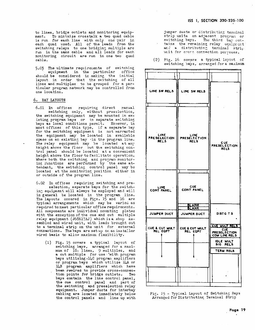
Fig. 15 - Typical Layout of Switchin~ Bays Arranged for Distri".:Jutin~ Terminal Strip
' I
to lines, bridge outlets and monitoring equipment. To minimize crosstalk a two quad cable is r1m for each line with only one ·pair in each quad used. All of the leads from the switching relays to one bridgin; multiple are run in the same cable and all leads for each .monitoring circuit are run in one two quad cable.
5.03 The ultimate requirer.1ents of swit;ching; equipment in the particular office
should be considered in making the initial layout in order that the switching of ali lines and multiples to be grouped for a particular program network may be controlled from one location.
6. BAY LAYOUTS
6.01 In offices requ1r1ng direct nanual switching only, without preselection,
the switching equipment may be mounted in existing program bays or in separate switchin~ bays as local conditions permit. Ho~.vever, in most offices of this type, if a separate bay for the switching equipment is not warranted the equipment may be located in available space on an existin; bay ·in the prograr.t line. Tl:e relay equipment may be located at an~' height above the floor but the switching control panel should be located at a convenient height above the floor to facilitate operation. Where both the switching and pro;rar:t monitorin~ !Unctions are perfo~ed by the same attendant, the switching control panel may be located at the monitorin~ position either in or outside of the program line.
6.02 In offices requirin~ switching and pre-selection, separate bays for the switch
in; equipment will always be employed and will in general be located in the pro~ram line. The layouts covered in Figs. 15 and 16 are typical arrangements which may be varied as required to meet particular office requirements. All components are individual mounting plates with the exception of the cue and cut multiple relay equipment (J68617AJ) which is a shop assembled and wired unit, with leads brought out to a terminal strip on· the unit for external conne.ctions. The bays are set up on an installer wired basis to allow maximum flexibility.
(l) Fig. 15 covers a typical layout of switching bays, arranged for a maximum of 18. lines, 9 multiples, and a cut multiple for use ·'with program bays utilizing-14C progrrun amplifiers or program bays which utilize l4A or l4B program amplifiers which have been rewired to provide cross-connection points for bridge outlets. Two bays contain the line control panel, the cu.e control panel and part of the switching and preselection relay equipment. Jumper ducts for interbay cabling are located immediately below tl1e control panels and line up with
jumper ducts or uistribt'tin; terninal strip units on adjacent proe;rru.1 or switching bays. The third ba~' l'O!"!
tains the remaining; relay equipr-cnt. an~ a distributin:; te~inal stri1· unit for c~o~~ co~nection pur~oses,
(2) Fig. 16 covers a typical layout of switching bays, arranged for a maximum
Page 19
SECTION 320-235-100
~~-~---! I
I CUE & CUT
I RELtE
I l
I t
i '
j
I i
I !
CUECOF'H P
! I I
! I
I LINI CONT P
I I i I CUE &CUT
REI- EI
i I
! !
: i
F' ig. 16 Arran~e
Page 20
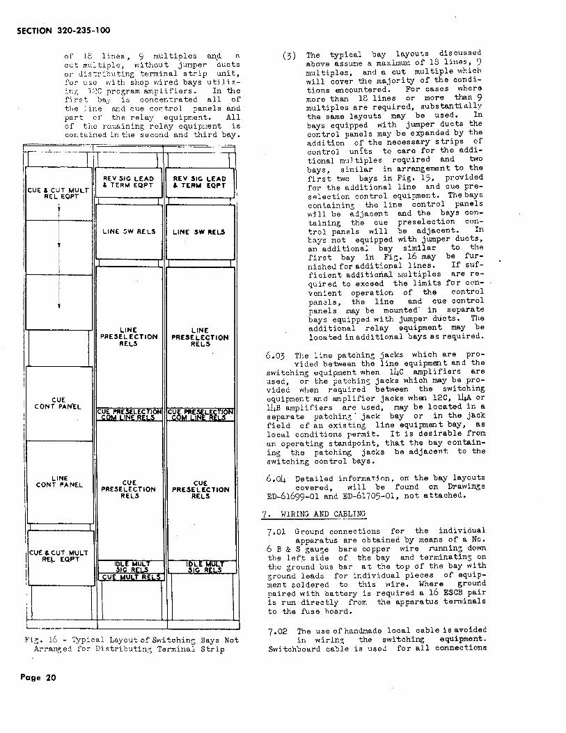
of lc lines, 9 multiples anft a celt multiple, I'Iithout junper ducts o1· disb·i-outing; terminal strip unit, i'oY" use v1i th shop wired bays utilizin::; l2C program amplifiers. In the first bay is concentrated all of the line and cue cor.trol panels and part cf the rela~' equipnent. All of the rc;;;aining; relRy equipuent is col> tained in the second and third bay.
---rt - --=--=
1 I I REV SIG LEAD REV $1G LEAD
MULT & TERM EQPT &. TER ... EQPT
QPT I 1 !
! I i I LINE !:JW RELS LINE SW IIIELS
I 1 I
LINE LINE PRESELECTION PRESELECTION
RELS RELS
AN'EL
cg~PRCi~~L~~l~ON cgg..rt~~L,~l]>N
E ANEL CUE CUE
PRESELECTION PRESELECTION RELS RELS
I
MULT QPT
lg}GE~,-~~ 1fi~E rr_~Ll UEUU T RE _s
- Typical Layout of Switch in:; Bays Not d for Distributin:~ Terminal Strip
(3) The typical bay layouts discussed above assume a maximw:: of 13 lines, 9 multiples, and a cut multiple which will cover the majority of the conditions encountered. For cases VI here more than 18 lines or more than 9 multiples are required, substantially the same layouts may be used, In bays equipped with jumper ducts the control panels may be expanded by the addition of the necessary strips of control unfts to care for the additional multiples required and two bays, similar in arrangement to the first two bays in Fig. 15, provided for the additional line and cue preselection control equipment. The bays containing - the line control panels will be adjacent and the bays containing the cue preselection control panels will be adjacent. In cays not equipped with jumper ducts, an additional bay similar to the first bay in Fi;. 16 may be furnishe<l for additional lines. If sufficient additional r.1ultiples are required to exceed the limits for convenient operation of the control panels, the line and cue control panels may be mounted· in separate bays equipped with jumper ducts. The additional relay equipment may be loca. ted in additional bays as required.
6.03 The line patching jacks which are pro-vided between the line equipment and the
switching equipment when 14C amplifiers are used, or the patching jacks which may be provided when required between the switching equipment and ar:;plifier jacks when 12C, 14A or lhB amplifiers are used, may be located in a separate patching· jack bay or in the jack field of an existing line equipment bay, as local conditions permit. It is desirable from un operating standpoint, that the bay containing the patching jacks be adjacent to the switching control bays.
6.04 Detailed informat.jon, on the bay layouts covered, will be found on Drawings
ED-61699-01 and ED-61705-01, not attached.
7 • WIRING AND CABLING
7.01 Ground connections for the individual apparatus are obtained by neans of a No.
6 B & S gau~e bare copper wire runnin~ down the lef:t side of the bay and terminatin~ on the ground bus bar at the top of the bay with ground leads for individual pieces of equipment soldered to this wire. Where ground paired with battery is required a 16 ESCB pair is run directly from the apparatus terminals to the fuse hoard.
7,02 The use of handmade local cable is avoided in w1r1n~ the switching equipment.
Switchboard cable is used for all connections
ISS 1 I SECTION 320-235-100
tO distributing terminal strips and wherever surface wiring is not practical be:;ween components on th@l bays. To minimize crosstalk, tr~smission leads of differentlevel or carrying different programs such as leads between switching relays and line patching jacks or between switching relays and monitoring equipment are run one circuit per two quad cable. Where all circuits are of the same level or carry the same program, such as circuits from the switching relays to the same bridgint; multiple, they are run ·in the same cable. In all cases the cable covering is kept intact as far along the run as possible to· maintain proper separation of circuits. Th~ detailed cablin9 and wiring arrangements are covered on ED-bl700-0l and on the cross connection figures of SD-55054-0l, SD-64782-01 and SD-64733-0l, not attached.
8. LIST OF..., DRAWINGS
8.01 Drawings for Reference But Not Attached
Title
Program Switching Circuit
Program Switching and Line Preselection Circuit
Program Switching Cue Preselection Circuit
Program Switching Equipment
Program Switching and Preselection Equipment
Cabling Arrangements of Program Switching
Drawing
SD-55054-01
SD-64782-01
SD-64783-01
ED-61705-01
ED-61699-01
ED-61700-01
Page 21 21 Pages