Embed Size (px)
Citation preview
1
DIGITAL
SWITCHING AND
TELECOM
NETWORKS
PEEC5404
7th
semester, ETC
2
Objective of the Module- I:
• To learn about different basic components that are
used in telephone exchanges
• Difference between an automatic exchange and
manual exchange
• Learn about different types of electronic exchanges
and about the software architecture used in an
electronic exchange.
• To differentiate between a single stage and a
multistage network.
• To understand the advantages of multistage network
over a single stage network.
• Design of multistage network to reduce blocking of
calls.
• Design of multistage network to reduce the number of
switching matrices
• To teach different types switching techniques that are
used in exchanges such as time division time
switching, time division space switching and
combination of both types of switching
MODULE-1:
1. INTRODUCTION:
Telecommunication networks carry information signals among entities, which
aregeographically far apart. An entity may be a computer or human being, a facsimile
machine, atele-printer, a data terminal and so on. The entities are involved in the process of
informationtransfer, which may be in the form of a telephone conversation (telephony) or a
file transferbetween two computers or message transfer between two terminals etc.
3
A switch transfers signals from one input port to an appropriate output. A basic problem is
then how to transfer traffic to the correct output port .In the early telephone network,
operator’s closed circuitsmanually. In modern circuit switches this is done electronically in
digital switches. If no circuit is available when a call is made, it will be blocked (rejected).
When a call is finished a connection teardown is required to make the circuit available for
another user.
Fundamentals of switching systems: Types of communication transmission mode:
Simplex : one way communication ex: Radio
Half Duplex : Two way communication shared by single channel ex: walkie
Talkie
Full Duplex : Two way communication simultaneously ex: Telephone
Therefore, telephone comes under the Full Duplex type of communication.
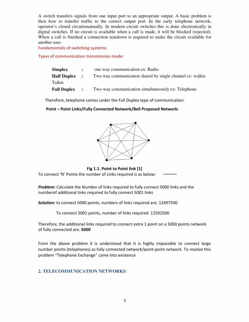
Point – Point Links/Fully Connected Network/Bell Proposed Network:
Fig 1.1. Point to Point link [1]
To connect ‘N’ Points the number of Links required is as below:
Problem: Calculate the Number of links required to fully connect 5000 links and the
numberof additional links required to fully connect 5001 links
Solution: to connect 5000 points, numbers of links required are: 12497500
To connect 5001 points, number of links required: 12502500
Therefore, the additional links required to connect extra 1 point on a 5000 points network
of fully connected are: 5000
From the above problem it is understood that it is highly impossible to connect large
number points (telephones) as fully connected network/point-point network. To resolve this
problem “Telephone Exchange” came into existence
2. TELECOMMUNICATION NETWORKS:
4
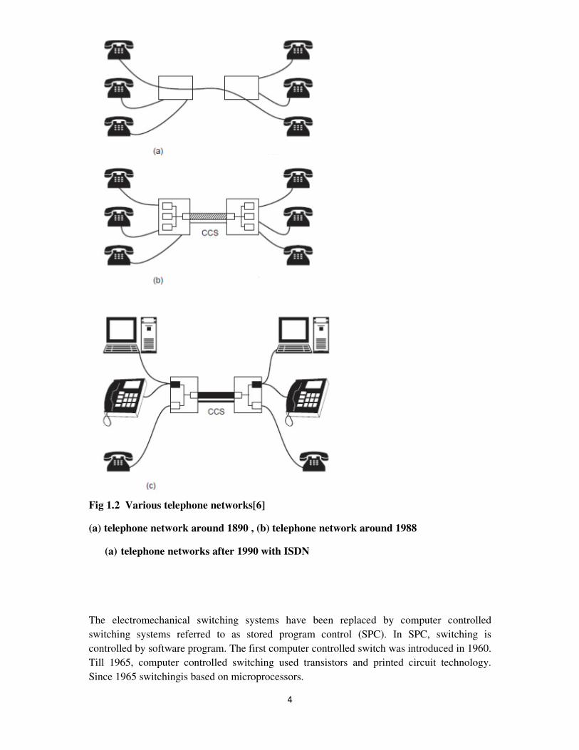
Fig 1.2 Various telephone networks[6]
(a) telephone network around 1890 , (b) telephone network around 1988
(a) telephone networks after 1990 with ISDN
The electromechanical switching systems have been replaced by computer controlled
switching systems referred to as stored program control (SPC). In SPC, switching is
controlled by software program. The first computer controlled switch was introduced in 1960.
Till 1965, computer controlled switching used transistors and printed circuit technology.
Since 1965 switchingis based on microprocessors.
5
3. SIGNAL CHARACTERISTICS:
Telecommunication is mainly concerned with the transmission of messages between two
distant points. The signal that contains the messages is usually converted into electrical waves
before transmission. Our voice is an analog signal which has amplitude and frequency
characteristic.
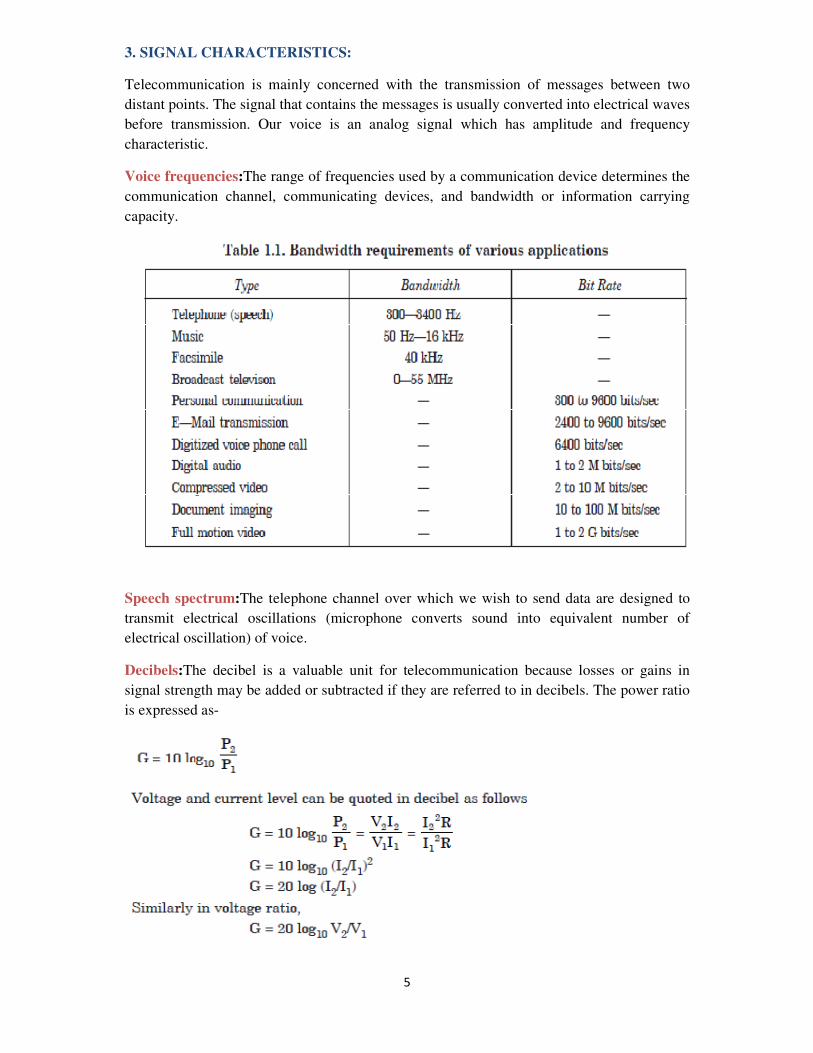
Voice frequencies:The range of frequencies used by a communication device determines the
communication channel, communicating devices, and bandwidth or information carrying
capacity.
Speech spectrum:The telephone channel over which we wish to send data are designed to
transmit electrical oscillations (microphone converts sound into equivalent number of
electrical oscillation) of voice.
Decibels:The decibel is a valuable unit for telecommunication because losses or gains in
signal strength may be added or subtracted if they are referred to in decibels. The power ratio
is expressed as-
6
4. ELEMENTS OF COMMUNICATION SWITCHING SYSTEM
The purpose of a telecommunication switching system is to provide the means to pass
information from any terminal device to any other terminal device selected by the
originator.Telecommunication system can be divided into four main parts. They are
1. End system or Instruments
2. Transmission system
3. Switching system
4. Signaling.
End Systems or Instruments:The end system or instruments are transmitters or receivers
that are responsible for sending information or decoding or inverting received information or
message into an intelligible message. End systems in the telephone network have evolved
from analog telephones to digital handsets and cellular phones. However, endless arrays of
other devices are being attached to telephone lines, including computer terminals used for
data transmission. Fig. 1.3 shows some of the end instruments.
Transmission System:Signals generated by the end system or the instruments should be
transported to the destination by some means. The transmission on links conveys the
information and control signals between the terminals and switching centers.
In general a communication path between two distinct points can be setup connecting a
number of transmission lines in tandem. The transmission links include two-wire lines,
coaxial cables microwave radio, optical fibers and satellites. Functionally, the communication
channels between switching system are referred to as trunks.
Switching System:The switching centers receives the control signals, messages or
conversations and forwards to the required destination, after necessary modification (link
amplifications) if necessary. A switching system is a collection of switching elements
arranged and controlled in such a way as to setup a communication path between any two
distant points.
Signaling Systems:A signaling system in a data communication networks
exchangessignaling information effectively between subscribers. The signaling systems are
essentialbuilding blocks in providing the ultimate objective of a worldwide automatic
telephone servicesstandardized. Signaling provides the interface between different national
systems. Theintroduction of signaling system was the big step in improving the PSTN.
7
The consultative committee on international telegraphy and telephony (CCITT) based in
Geneva, recommended seven formats related to signaling.
5. CRITERIA FOR THE DESIGN OF TELECOMMUNICATION SYSTEM
The design for telephone switching center or equipment requirement in a telecommunication
system is determined on the basis of the traffic intensity of the busy hour. The traffic intersity
is defined as the product of the calling rate and the average holding time. The busy hour is
defined as that continuous sixty-minute period during which the traffic intensity is highest.
Otherwise the average holding time is the average duration of occupancy of traffic path by a
call.
Grade of Service:In telephone field, the so called busy hour traffic is used for planning
purposes. Once the statistical properties of the traffic are known, the objective for the
performance of a switching system should be stated.
GOS is a measure of congestion expressed as the probability that a call will be blocked or
delayed. Thus when dealing with GOS in traffic engineering, the clear understanding .of
blocking criteria, delay criteria and congestion are essential.
Blocking criteria:If the design of a system is based on the fraction of calls blocked (the
blocking probability), then the system is said to be engineered on a blocking basis or call loss
basis. Blocking can occur if all devices are occupied when a demand of service is initiated.
Delay criteria:If the design of a system is based on the fraction of calls delayed longer than a
specified length of time (the delay probability), the system is said to be a waiting system or
engineered on a delay basis. Delay criteria are used in telephone systems for the
dimensioning of registers. In waiting system, a GOS objective could be either the percentage
of calls which are delayed or the percentage, which is delayed more than a certain length of
time.
Congestion:It is the condition in a switching center when a subscriber cannot obtain a
connection to the wanted subscriber immediately. In a circuit switching system, there will be
a period of congestion during which no new calls can be accepted. There are two ways of
specifying congestion.
1. Time congestion: It is the probability that all servers are busy. It is also called the
probability of blocking.
2. Call congestion:It is the proportion of calls arising that do not find a free server. Call
congestion is a loss system and also known as the probability of loss while in a delay system
it is referred to as the probability of waiting.
Measure of GOS:GOS is expressed as a probability. The GOS of 2% (0.02) mean that 98%
of the calls will reach a called instrument if it is free. Generally, GOS is quoted as P.02 or
simply P02 to represent a network busy probability of 0.02. GOS is applied to a terminal-to-
terminal connection. For the system connection many switching centers, the system is
generally broken into following components.
8
(i) An internal call (calling subscriber to switching office)
(ii) An outgoing call to the trunk network (switching office to trunk)
(iii) The trunk network (trunk to trunk)
(iv) A terminating call (switching office to called subscriber)
The GOS of each component is called component GOS. The GOS for internal calls is 3 to
5%, for trunk calls 1-3%, for outgoing calls 2% and for terminating calls 2%. The overall
GOS of a system is approximately the sum of the component grade of service. In practice, in
order to ensure that the GOS does not deteriorate disastrously if the actual busy hour traffic
exceeds the mean; GOS are specified 10% or 20% more of the mean.
6. FUNDAMENTALS FOR THE DESIGN OF TELECOMMUNICATION
NETWORK:
A telephone network is composed of a variety of all processing equipment, interstate
switching links and inters office trunks. Because of the random nature of the call request, the
design ofequipment switching links and trunks are quite difficult. Thus, the traffic analysis is
thefundamental request for the design of cost effective, efficient and effective configuration
ofnetworks. The effectiveness of a network can be evaluated interms of how much traffic
itcarries under normal or average loads and how often the traffic volume exceeds the capacity
ofthe network.Fundamental problem in the design of telecommunication networks concerns
thedimensioning of a route. To dimension the route, volume of traffic required grade of
serviceand capacity (in bits per sec) must be known.
Traffic:In telecommunication system, traffic is defined as the occupancy of the serverin the
network. There are two types of traffic viz. voice traffic and data traffic. For voice traffic,the
calling rate is defined as the number of calls per traffic path during the busy hour. In a day,the
60 minutes interval in which the traffic is highest is called busy hour (BH).
Average occupancy:If the average number of calls to and from a terminal during aperiod T
second is ‘n’ and the average holding time is ‘h’ seconds, the average occupancy of
theterminal is given by
The average occupancy is also referred as traffic flow of traffic intensity. The
internationalunit of telephone traffic is the Erlang.
The average occupancy is also referred as traffic flow of traffic intensity. The international
unit of telephone traffic is the Erlang.
7.DISTRIBUTED&CENTRALIZED SWITCHING SYSTEM
Distributed Model
9
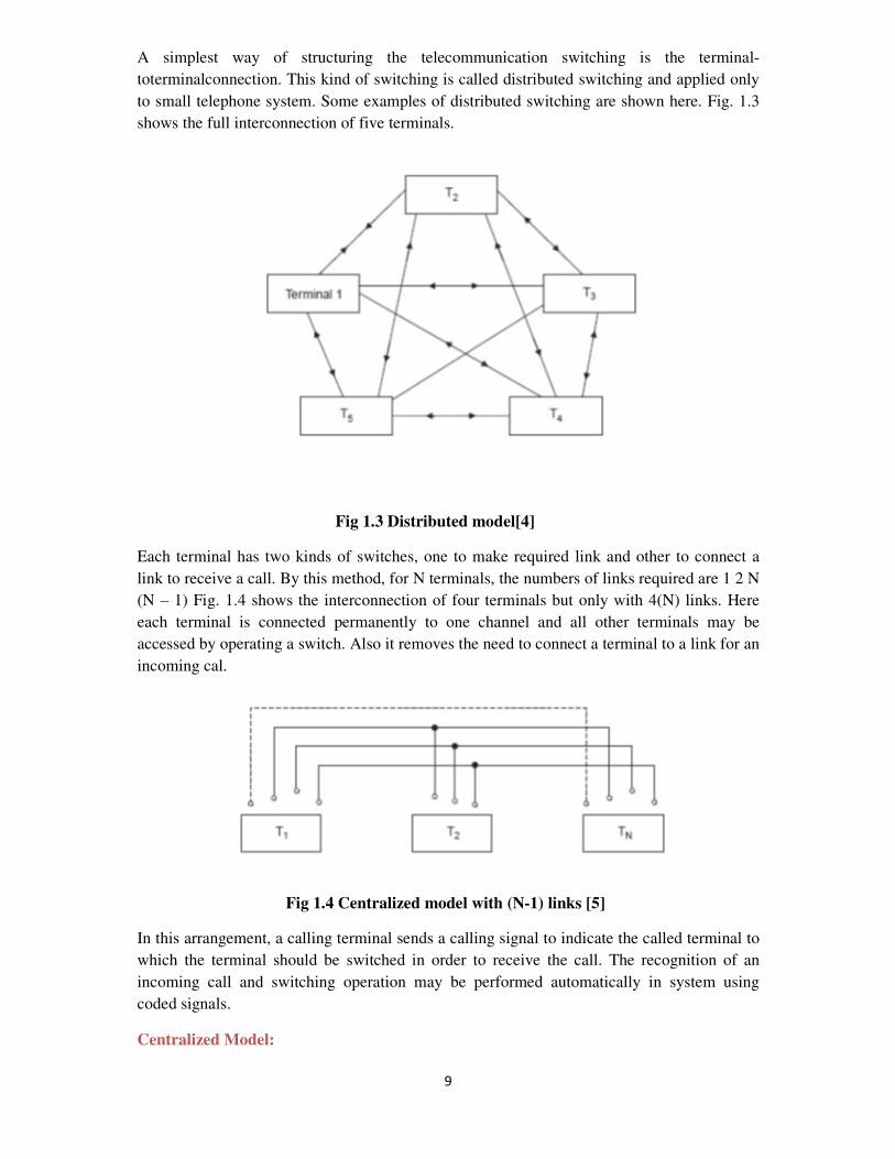
A simplest way of structuring the telecommunication switching is the terminal-
toterminalconnection. This kind of switching is called distributed switching and applied only
to small telephone system. Some examples of distributed switching are shown here. Fig. 1.3
shows the full interconnection of five terminals.
Fig 1.3 Distributed model[4]
Each terminal has two kinds of switches, one to make required link and other to connect a
link to receive a call. By this method, for N terminals, the numbers of links required are 1 2 N
(N – 1) Fig. 1.4 shows the interconnection of four terminals but only with 4(N) links. Here
each terminal is connected permanently to one channel and all other terminals may be
accessed by operating a switch. Also it removes the need to connect a terminal to a link for an
incoming cal.
Fig 1.4 Centralized model with (N-1) links [5]
In this arrangement, a calling terminal sends a calling signal to indicate the called terminal to
which the terminal should be switched in order to receive the call. The recognition of an
incoming call and switching operation may be performed automatically in system using
coded signals.
Centralized Model:
10
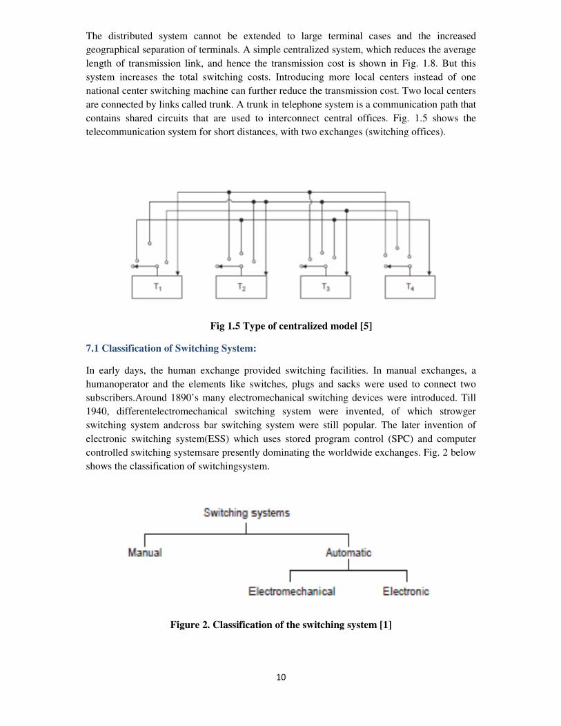
The distributed system cannot be extended to large terminal cases and the increased
geographical separation of terminals. A simple centralized system, which reduces the average
length of transmission link, and hence the transmission cost is shown in Fig. 1.8. But this
system increases the total switching costs. Introducing more local centers instead of one
national center switching machine can further reduce the transmission cost. Two local centers
are connected by links called trunk. A trunk in telephone system is a communication path that
contains shared circuits that are used to interconnect central offices. Fig. 1.5 shows the
telecommunication system for short distances, with two exchanges (switching offices).
Fig 1.5 Type of centralized model [5]
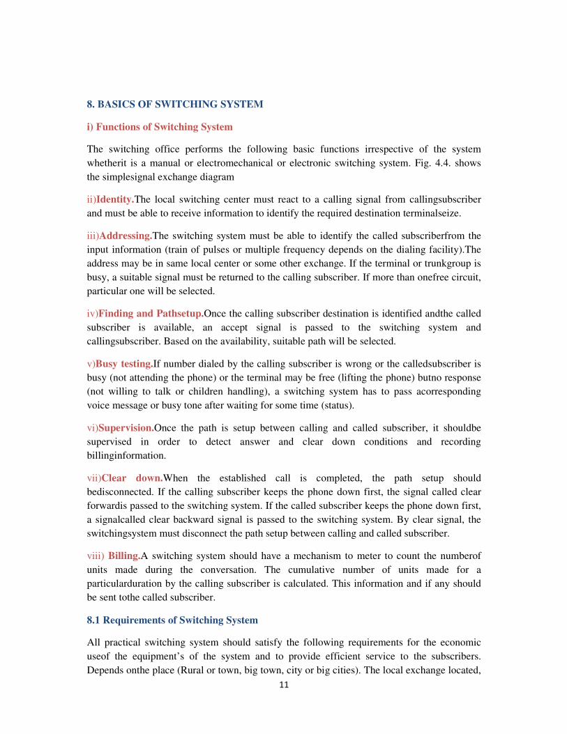
7.1 Classification of Switching System:
In early days, the human exchange provided switching facilities. In manual exchanges, a
humanoperator and the elements like switches, plugs and sacks were used to connect two
subscribers.Around 1890’s many electromechanical switching devices were introduced. Till
1940, differentelectromechanical switching system were invented, of which strowger
switching system andcross bar switching system were still popular. The later invention of
electronic switching system(ESS) which uses stored program control (SPC) and computer
controlled switching systemsare presently dominating the worldwide exchanges. Fig. 2 below
shows the classification of switchingsystem.
Figure 2. Classification of the switching system [1]
11
8. BASICS OF SWITCHING SYSTEM
i) Functions of Switching System
The switching office performs the following basic functions irrespective of the system
whetherit is a manual or electromechanical or electronic switching system. Fig. 4.4. shows
the simplesignal exchange diagram
ii)Identity.The local switching center must react to a calling signal from callingsubscriber
and must be able to receive information to identify the required destination terminalseize.
iii)Addressing.The switching system must be able to identify the called subscriberfrom the
input information (train of pulses or multiple frequency depends on the dialing facility).The
address may be in same local center or some other exchange. If the terminal or trunkgroup is
busy, a suitable signal must be returned to the calling subscriber. If more than onefree circuit,
particular one will be selected.
iv)Finding and Pathsetup.Once the calling subscriber destination is identified andthe called
subscriber is available, an accept signal is passed to the switching system and
callingsubscriber. Based on the availability, suitable path will be selected.
v)Busy testing.If number dialed by the calling subscriber is wrong or the calledsubscriber is
busy (not attending the phone) or the terminal may be free (lifting the phone) butno response
(not willing to talk or children handling), a switching system has to pass acorresponding
voice message or busy tone after waiting for some time (status).
vi)Supervision.Once the path is setup between calling and called subscriber, it shouldbe
supervised in order to detect answer and clear down conditions and recording
billinginformation.
vii)Clear down.When the established call is completed, the path setup should
bedisconnected. If the calling subscriber keeps the phone down first, the signal called clear
forwardis passed to the switching system. If the called subscriber keeps the phone down first,
a signalcalled clear backward signal is passed to the switching system. By clear signal, the
switchingsystem must disconnect the path setup between calling and called subscriber.
viii) Billing.A switching system should have a mechanism to meter to count the numberof
units made during the conversation. The cumulative number of units made for a
particularduration by the calling subscriber is calculated. This information and if any should
be sent tothe called subscriber.
8.1 Requirements of Switching System
All practical switching system should satisfy the following requirements for the economic
useof the equipment’s of the system and to provide efficient service to the subscribers.
Depends onthe place (Rural or town, big town, city or big cities). The local exchange located,
12
the serviceprovided to the subscriber may vary. Some important requirements are discussed
briefly.
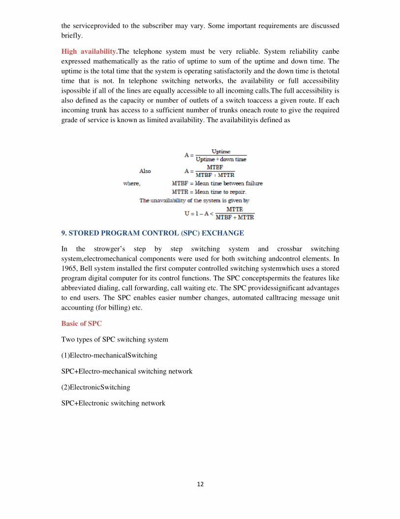
High availability.The telephone system must be very reliable. System reliability canbe
expressed mathematically as the ratio of uptime to sum of the uptime and down time. The
uptime is the total time that the system is operating satisfactorily and the down time is thetotal
time that is not. In telephone switching networks, the availability or full accessibility
ispossible if all of the lines are equally accessible to all incoming calls.The full accessibility is
also defined as the capacity or number of outlets of a switch toaccess a given route. If each
incoming trunk has access to a sufficient number of trunks oneach route to give the required
grade of service is known as limited availability. The availabilityis defined as
9. STORED PROGRAM CONTROL (SPC) EXCHANGE
In the strowger’s step by step switching system and crossbar switching
system,electromechanical components were used for both switching andcontrol elements. In
1965, Bell system installed the first computer controlled switching systemwhich uses a stored
program digital computer for its control functions. The SPC conceptspermits the features like
abbreviated dialing, call forwarding, call waiting etc. The SPC providessignificant advantages
to end users. The SPC enables easier number changes, automated calltracing message unit
accounting (for billing) etc.
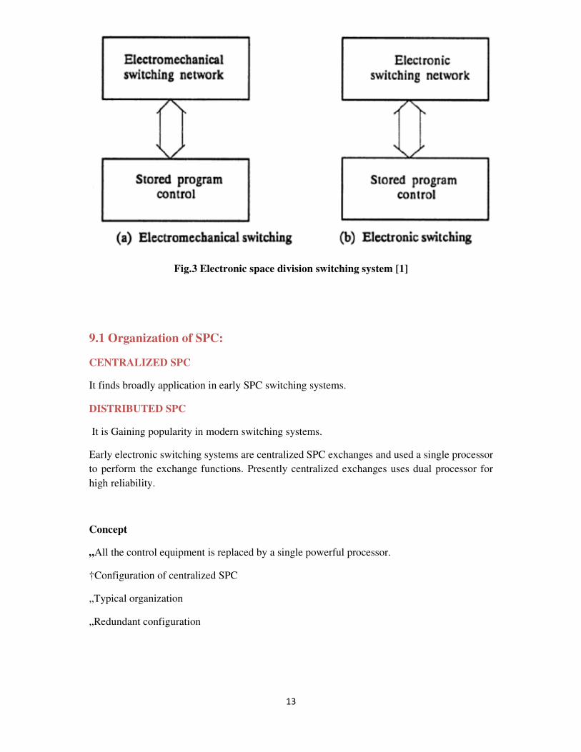
Basic of SPC
Two types of SPC switching system
(1)Electro-mechanicalSwitching
SPC+Electro-mechanical switching network
(2)ElectronicSwitching
SPC+Electronic switching network
13
Fig.3 Electronic space division switching system [1]
9.1 Organization of SPC:
CENTRALIZED SPC
It finds broadly application in early SPC switching systems.
DISTRIBUTED SPC
It is Gaining popularity in modern switching systems.
Early electronic switching systems are centralized SPC exchanges and used a single processor
to perform the exchange functions. Presently centralized exchanges uses dual processor for
high reliability.
Concept
„All the control equipment is replaced by a single powerful processor.
†Configuration of centralized SPC
„Typical organization
„Redundant configuration
14
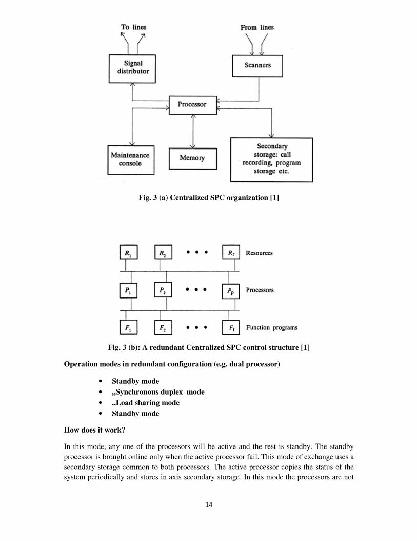
Fig. 3 (a) Centralized SPC organization [1]
Fig. 3 (b): A redundant Centralized SPC control structure [1]
Operation modes in redundant configuration (e.g. dual processor)
• Standby mode
• „Synchronous duplex mode
• „Load sharing mode
• Standby mode
How does it work?
In this mode, any one of the processors will be active and the rest is standby. The standby
processor is brought online only when the active processor fail. This mode of exchange uses a
secondary storage common to both processors. The active processor copies the status of the
system periodically and stores in axis secondary storage. In this mode the processors are not
15
connected directly. In secondary storage, programs and instructions related to the control
functions, routine programs and other required information are stored.
„All processors have the same capability to control the switching procedure.
„One processor is active and the other is on standby, both hardware and software wise.
„The standby processor is brought online only when the active processor fails.
How does the standby processor take over the control properly?
„State of the exchange system should be clear to the standby processor as its starting
point.
Which of the subscribers are busy or free?
Which of the trunks are busy or free?
Which of the paths are connected through the switching network?
Reconstitution of the state
Scanning:
� The standby processor scans all status signals as soon as it is brought into
operation.
� Only the calls which are being established at the time of failure are disturbed.
� Only feasible for small exchanges.
� Shared secondary storage: popular.
Shared secondary storage:
� The active processor copies system status into a secondary storage periodically,
say every 5 seconds.
� As soon as a switchover occurs, the online processor loads the most recent update
of the system status from the secondary storage and continues the operations.
� Only the calls which changed status between the last update and the failure are
disturbed.
� Feasible for large exchanges.
16
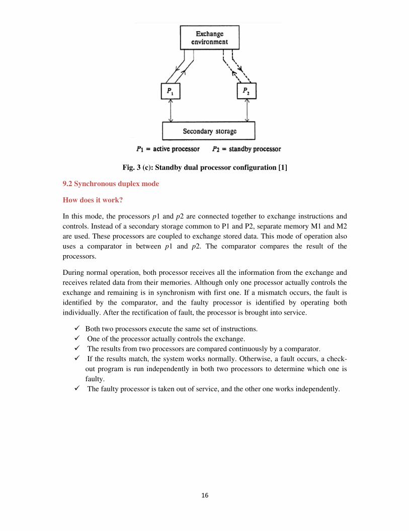
Fig. 3 (c): Standby dual processor configuration [1]
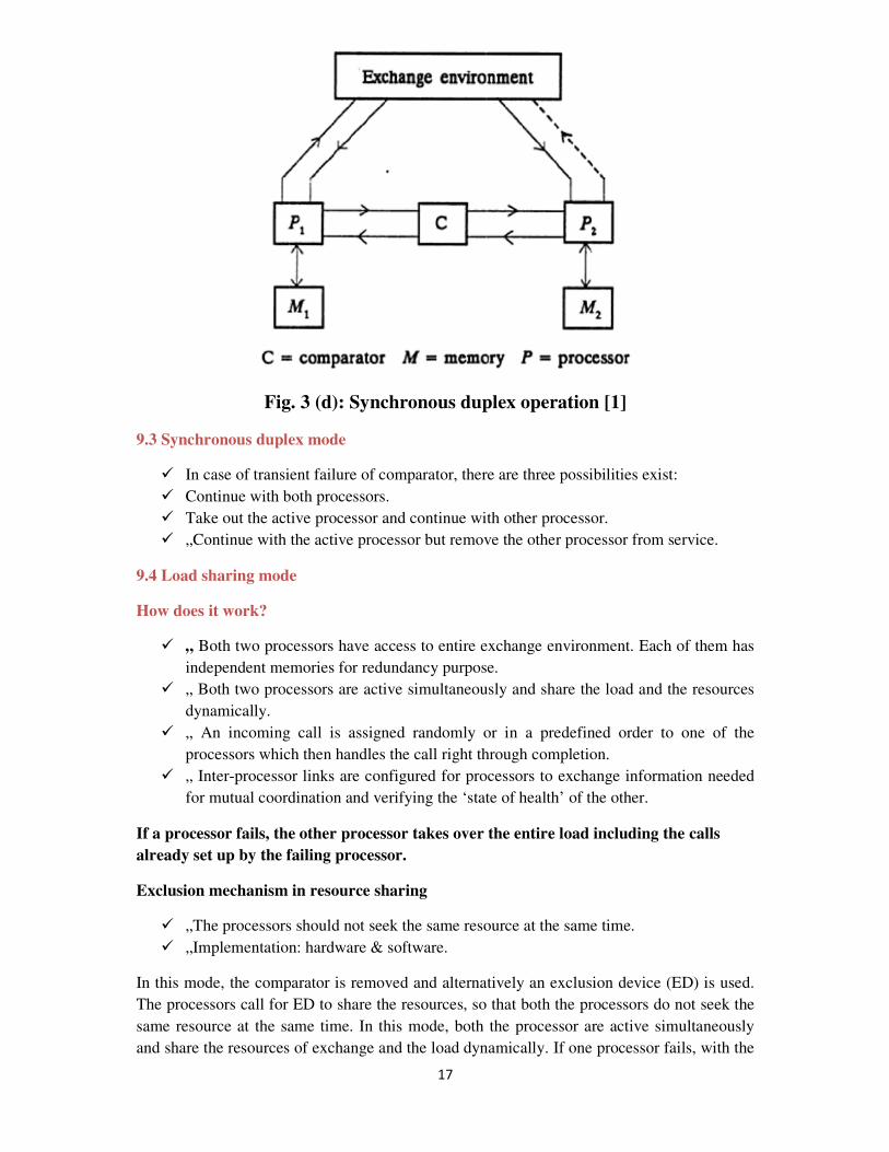
9.2 Synchronous duplex mode
How does it work?
In this mode, the processors p1 and p2 are connected together to exchange instructions and
controls. Instead of a secondary storage common to P1 and P2, separate memory M1 and M2
are used. These processors are coupled to exchange stored data. This mode of operation also
uses a comparator in between p1 and p2. The comparator compares the result of the
processors.
During normal operation, both processor receives all the information from the exchange and
receives related data from their memories. Although only one processor actually controls the
exchange and remaining is in synchronism with first one. If a mismatch occurs, the fault is
identified by the comparator, and the faulty processor is identified by operating both
individually. After the rectification of fault, the processor is brought into service.
� Both two processors execute the same set of instructions.
� One of the processor actually controls the exchange.
� The results from two processors are compared continuously by a comparator.
� If the results match, the system works normally. Otherwise, a fault occurs, a check-
out program is run independently in both two processors to determine which one is
faulty.
� The faulty processor is taken out of service, and the other one works independently.
17
Fig. 3 (d): Synchronous duplex operation [1]
9.3 Synchronous duplex mode
� In case of transient failure of comparator, there are three possibilities exist:
� Continue with both processors.
� Take out the active processor and continue with other processor.
� „Continue with the active processor but remove the other processor from service.
9.4 Load sharing mode
How does it work?
� „ Both two processors have access to entire exchange environment. Each of them has
independent memories for redundancy purpose.
� „ Both two processors are active simultaneously and share the load and the resources
dynamically.
� „ An incoming call is assigned randomly or in a predefined order to one of the
processors which then handles the call right through completion.
� „ Inter-processor links are configured for processors to exchange information needed
for mutual coordination and verifying the ‘state of health’ of the other.
If a processor fails, the other processor takes over the entire load including the calls
already set up by the failing processor.
Exclusion mechanism in resource sharing
� „The processors should not seek the same resource at the same time.
� „Implementation: hardware & software.
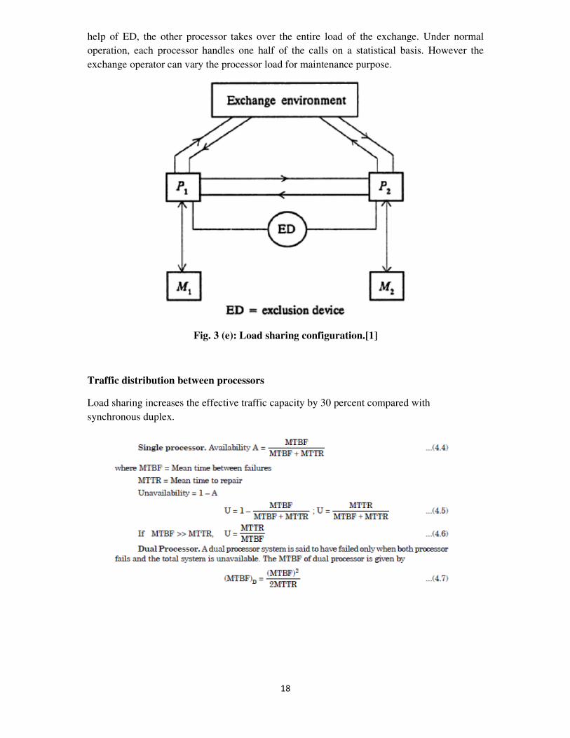
In this mode, the comparator is removed and alternatively an exclusion device (ED) is used.
The processors call for ED to share the resources, so that both the processors do not seek the
same resource at the same time. In this mode, both the processor are active simultaneously
and share the resources of exchange and the load dynamically. If one processor fails, with the
18
help of ED, the other processor takes over the entire load of the exchange. Under normal
operation, each processor handles one half of the calls on a statistical basis. However the
exchange operator can vary the processor load for maintenance purpose.
Fig. 3 (e): Load sharing configuration.[1]
Traffic distribution between processors
Load sharing increases the effective traffic capacity by 30 percent compared with
synchronous duplex.
19
Distributed SPC
The introduction of distributed SPC enabled customers to be provided with a wider range of
services than those available with centralized and electromechanical switching system.
Instead of all processing being performed by a one or two processor in centralized switching,
functions are delegated to separate small processors (referred as regional processors). But
central processors are still required to direct the regional processors and to perform more
complex tasks. The distributed SPC offers better availability and reliability than the
centralized SPC. Entire exchange control functions may be decomposed either horizontally or
vertically for distributed processing. In vertical decomposition, the exchange environment is
divided into several blocks and each block is assigned to a processor that performs all control
functions related to that block of equipment. In horizontal decomposition, each processor
performs one or some of the exchange control functions. Figure shows the distributed control
where switching equipment is divided into parts, each of which has its own processor.
CONCEPT OF DISTRIBUTED SPC
The control functions are shared by many processors within the exchanges.
� Background
� Low cost processors
Advantages
• Better Availability
• Better Reliability
Decomposition of Control Functions
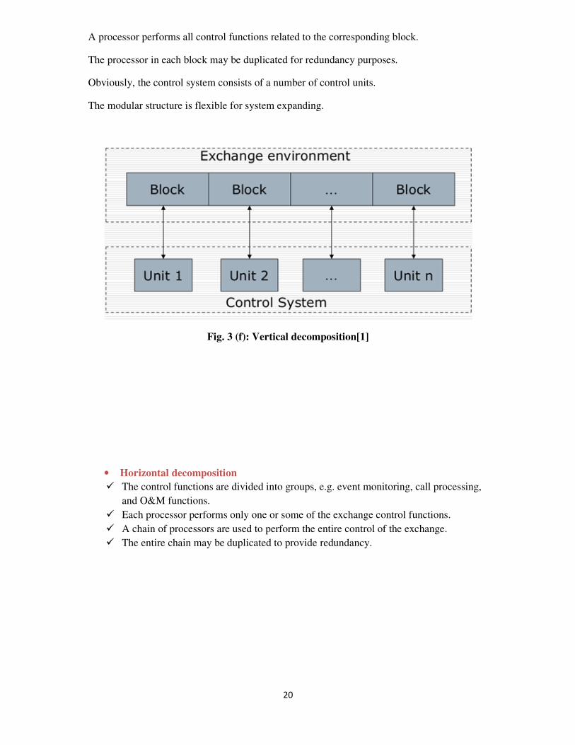
• Vertical decomposition
The exchange environment is divided into several blocks.
Each block is assigned to a processor.
20
A processor performs all control functions related to the corresponding block.
The processor in each block may be duplicated for redundancy purposes.
Obviously, the control system consists of a number of control units.
The modular structure is flexible for system expanding.
Fig. 3 (f): Vertical decomposition[1]
• Horizontal decomposition
� The control functions are divided into groups, e.g. event monitoring, call processing,
and O&M functions.
� Each processor performs only one or some of the exchange control functions.
� A chain of processors are used to perform the entire control of the exchange.
� The entire chain may be duplicated to provide redundancy.
21
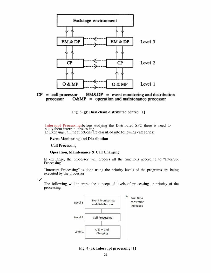
Fig. 3 (g): Dual chain distributed control [1]
� Interrupt Processing:before studying the Distributed SPC there is need to studyabout interrupt processing
� In Exchange, all the functions are classified into following categories:
Event Monitoring and Distribution
Call Processing
Operation, Maintenance & Call Charging
� In exchange, the processor will process all the functions according to “Interrupt
Processing”
� “Interrupt Processing” is done using the priority levels of the programs are being executed by the processor
� The following will interpret the concept of levels of processing or priority of the processing
Fig. 4 (a): Interrupt processing [1]
22
�From the above diagram it is understood that
o Level 3 Process : Event Monitoring and Distribution
o Level2 Process : Call Processing
o Level 1 Process : Operation, Maintenance & Call Charging
o and the priority of Level 3 > Level 2 > Level 1
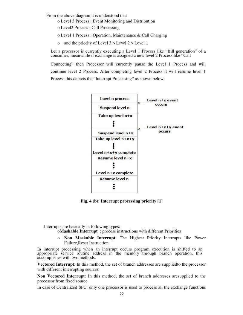
� Let a processor is currently executing a Level 1 Process like “Bill generation” of a consumer, meanwhile if exchange is assigned a new level 2 Process like “Call
Connecting” then Processor will currently pause the Level 1 Process and will
continue level 2 Process. After completing level 2 Process it will resume level 1
Process this depicts the “Interrupt Processing” as shown below:
Fig. 4 (b): Interrupt processing priority [1]
Interrupts are basically in following types: oMaskable Interrupt : process instructions with different Priorities
o Non Maskable Interrupt: The Highest Priority Interrupts like Power
Failure,Reset Instruction In interrupt processing when an interrupt occurs program execution is shifted to an appropriate service routine address in the memory through branch operation, this accomplishes with two methods:
Vectored Interrupt: In this method, the set of branch addresses are suppliedto the processor with different interrupting sources Non Vectored Interrupt: In this method, the set of branch addresses aresupplied to the processor from fixed source In case of Centralized SPC, only one processor is used to process all the exchange functions
23
where as in case of “Distributed SPC” three different processors are used for different levels of operations
Level 3 Processing
Level 3 Processing will include the functions like: � Scanning � Distribution
� Marking
� Controlling all incoming & Outgoing local calls, STD Calls, ISD Calls, Fax &Data services
� Control of all functions are carried by specially designed Processors
with � “Micro-programmed Control”
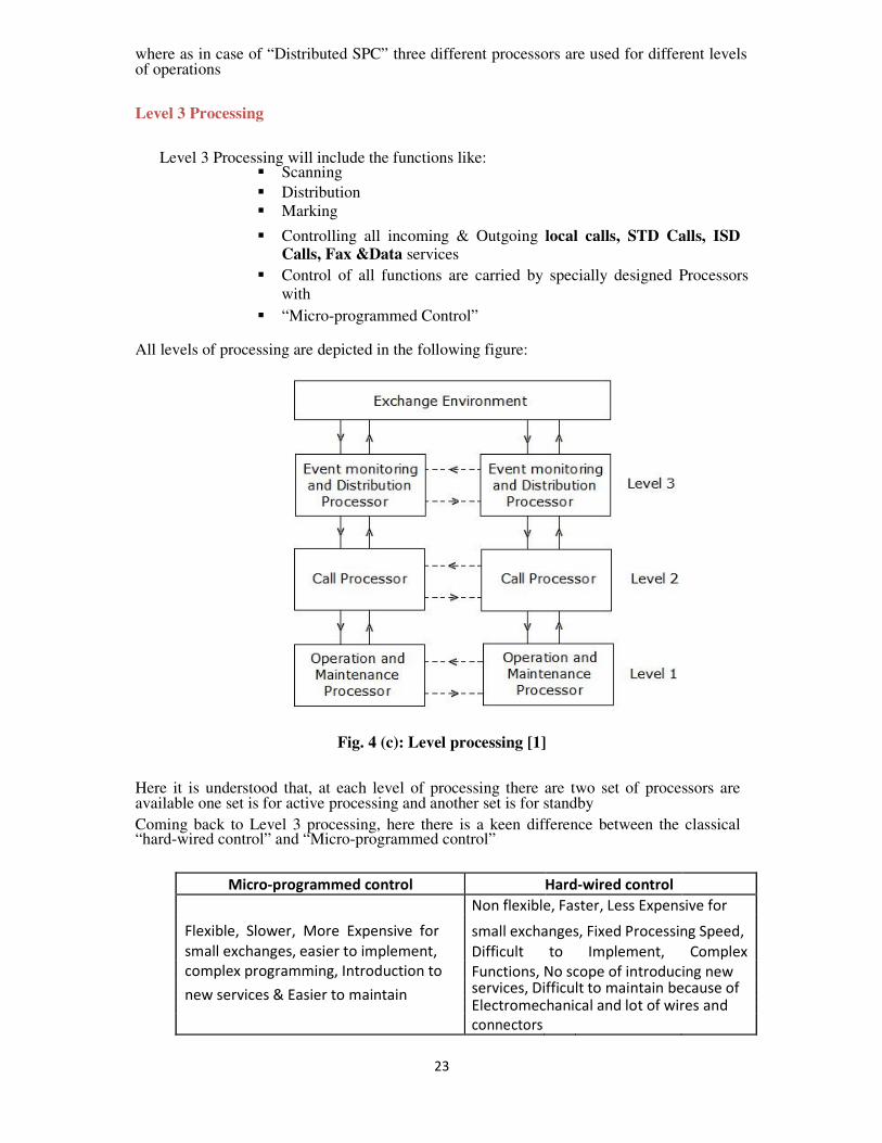
All levels of processing are depicted in the following figure:
Fig. 4 (c): Level processing [1]
Here it is understood that, at each level of processing there are two set of processors are available one set is for active processing and another set is for standby
Coming back to Level 3 processing, here there is a keen difference between the classical “hard-wired control” and “Micro-programmed control”
Micro-programmed control Hard-wired control
Non flexible, Faster, Less Expensive for
Flexible, Slower, More Expensive for small exchanges, Fixed Processing Speed,
small exchanges, easier to implement, Difficult to Implement, Complex
complex programming, Introduction to Functions, No scope of introducing new
new services & Easier to maintain services, Difficult to maintain because of
Electromechanical and lot of wires and
connectors
24
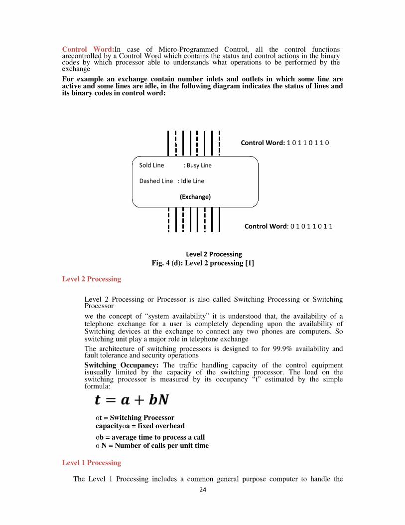
Control Word:In case of Micro-Programmed Control, all the control functions arecontrolled by a Control Word which contains the status and control actions in the binary codes by which processor able to understands what operations to be performed by the exchange
For example an exchange contain number inlets and outlets in which some line are active and some lines are idle, in the following diagram indicates the status of lines and its binary codes in control word:
Control Word: 1 0 1 1 0 1 1 0
Sold Line : Busy Line
Dashed Line : Idle Line
(Exchange)
Control Word: 0 1 0 1 1 0 1 1
Level 2 Processing
Fig. 4 (d): Level 2 processing [1]
Level 2 Processing
� Level 2 Processing or Processor is also called Switching Processing or Switching Processor
� we the concept of “system availability” it is understood that, the availability of a telephone exchange for a user is completely depending upon the availability of Switching devices at the exchange to connect any two phones are computers. So switching unit play a major role in telephone exchange
� The architecture of switching processors is designed to for 99.9% availability and fault tolerance and security operations
� Switching Occupancy: The traffic handling capacity of the control equipment isusually limited by the capacity of the switching processor. The load on the switching processor is measured by its occupancy “t” estimated by the simple formula:
ot = Switching Processor capacityoa = fixed overhead
ob = average time to process a call o N = Number of calls per unit time
Level 1 Processing
The Level 1 Processing includes a common general purpose computer to handle the
25
following operations:
• Bill Charging
• Bill distributing
Monitor Traffic
• Fault tolerance
• Customer Support
• Making a new Service
• Disconnecting a requested serviceProcuring new Equipment
• Paying power bills of exchange.
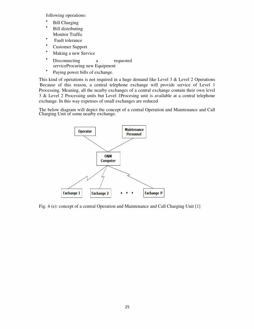
This kind of operations is not required in a huge demand like Level 3 & Level 2 Operations .Because of this reason, a central telephone exchange will provide service of Level 1
Processing. Meaning, all the nearby exchanges of a central exchange contain their own level
3 & Level 2 Processing units but Level 1Procesing unit is available at a central telephone
exchange. In this way expenses of small exchanges are reduced
The below diagram will depict the concept of a central Operation and Maintenance and Call Charging Unit of some nearby exchange. Fig. 4 (e): concept of a central Operation and Maintenance and Call Charging Unit [1]
26
9.5 Software Architecture
Software is basically two types:
i. System Software (Operating System)
ii. Application Software (Software based on Operating System)
Therefore a Special Design and Development is to be done for Switching Operating System
Process: an instruction executed by the processor is commonly called as a “Process”
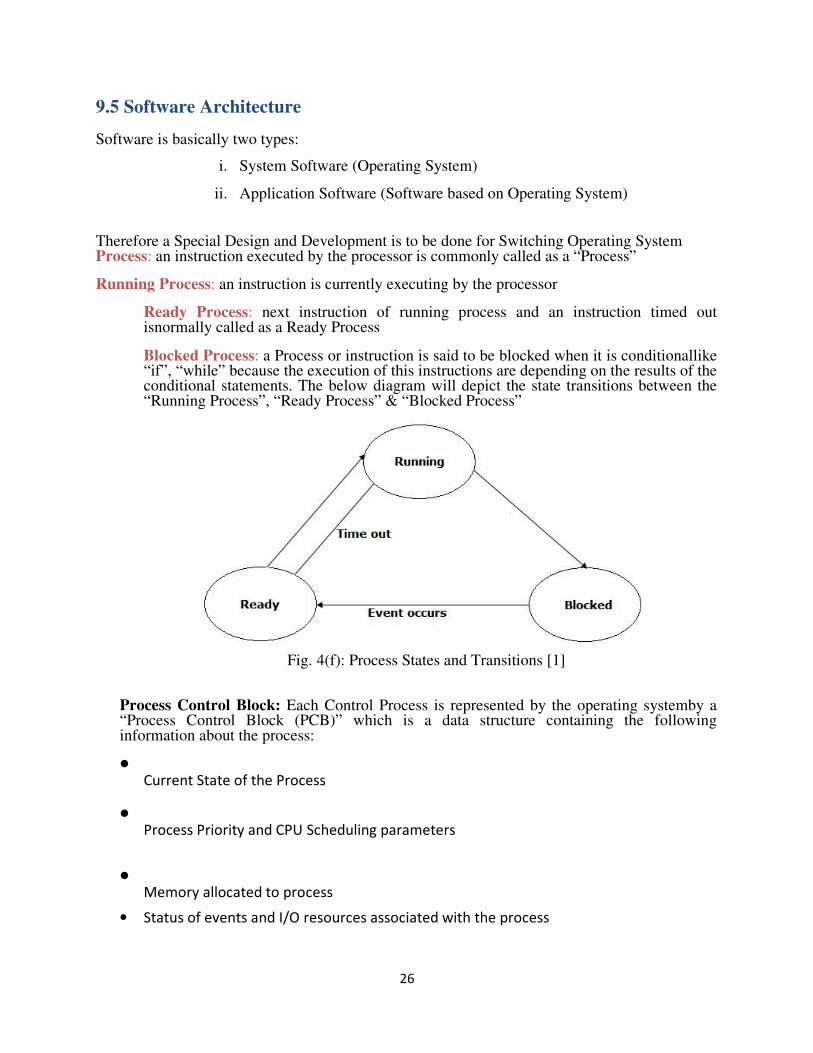
Running Process: an instruction is currently executing by the processor
Ready Process: next instruction of running process and an instruction timed out isnormally called as a Ready Process
Blocked Process: a Process or instruction is said to be blocked when it is conditionallike “if”, “while” because the execution of this instructions are depending on the results of the conditional statements. The below diagram will depict the state transitions between the “Running Process”, “Ready Process” & “Blocked Process”
Fig. 4(f): Process States and Transitions [1]
Process Control Block: Each Control Process is represented by the operating systemby a “Process Control Block (PCB)” which is a data structure containing the following information about the process:
• Current State of the Process
• Process Priority and CPU Scheduling parameters
• Memory allocated to process
• Status of events and I/O resources associated with the process
27
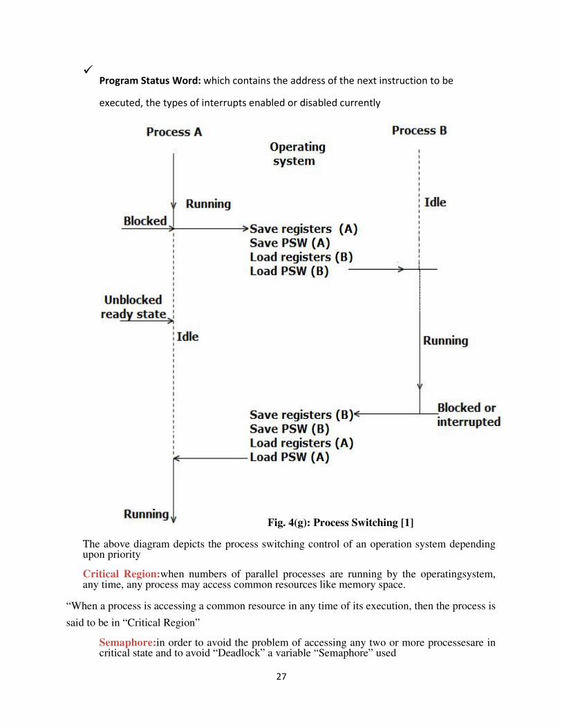
� Program Status Word: which contains the address of the next instruction to be
executed, the types of interrupts enabled or disabled currently
Fig. 4(g): Process Switching [1] The above diagram depicts the process switching control of an operation system depending upon priority
Critical Region:when numbers of parallel processes are running by the operatingsystem, any time, any process may access common resources like memory space.
“When a process is accessing a common resource in any time of its execution, then the process is
said to be in “Critical Region”
Semaphore:in order to avoid the problem of accessing any two or more processesare in critical state and to avoid “Deadlock” a variable “Semaphore” used
28
Semaphore contain a number (which is equal to the number processes of accessingthe common resources or be in critical state) by accessing this number operating system can manage between different processes in “Critical State” and by which, “Deadlock” is avoided.
9.5.1 SOFTWARE PRODUCTION
Basic factors associated with switching software
• Complexity and size of the software
• Long working life required
• Real time operation
• Stringent reliability and availability
• Software portability
Four stages in software production
� Functional specification
� Formal description and detailed specification
� Coding and verification
� †Testing and debugging
9.6 ENHANCED SERVICES
Categories of enhanced services
1. Services associated with the calling subscriber and designed to reduce the time spent on
dialing and the number of dialing errors.
2. Services associated with the called subscriber and designed to increase the call completion
rate.
3. Services involving more than two parties.
4. Miscellaneous services.
Category 1
Abbreviated dialing
Recorded number calls or no dialing calls.
Call back when free
Category 2
Call forwarding
29
Operator answer
Category 3
†Calling number record
†Call waiting
†Consultation hold
†Conference calls
Category 4
†Automatic alarm
†STD barring
†Malicious call tracing
STD:subscriber trunk dialing
9.7 TWO-STAGE NETWORKS
For any single stage network, there exists an equivalent multistage network.
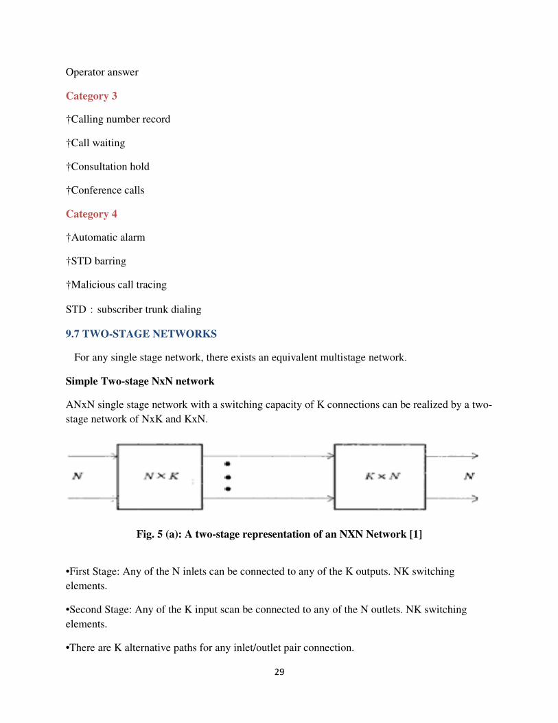
Simple Two-stage NxN network
ANxN single stage network with a switching capacity of K connections can be realized by a two-
stage network of NxK and KxN.
Fig. 5 (a): A two-stage representation of an NXN Network [1]
•First Stage: Any of the N inlets can be connected to any of the K outputs. NK switching
elements.
•Second Stage: Any of the K input scan be connected to any of the N outlets. NK switching
elements.
•There are K alternative paths for any inlet/outlet pair connection.
30
Simple Two-stage NxN network
Full connectivity/full availability
Any of the N inlets can be connected to any of the N outlets.
Example
Assume 10% of the subscribers to be active on average. Set K to be N/16. The number of
switching elements is S=N2/8.
For N=1024, we have K=64, S=131072.
Note: Feasibility & Flexibility
Two-Stage Networks
Single stage vs. multistage networks
Inlet to outlet connection
Quality of link
Utility of cross-points
Establishment of a specific connection
Cross-point & path Redundancy
Number of cross-points
Capacitive loading problem
Blocking feature
Call establishing time
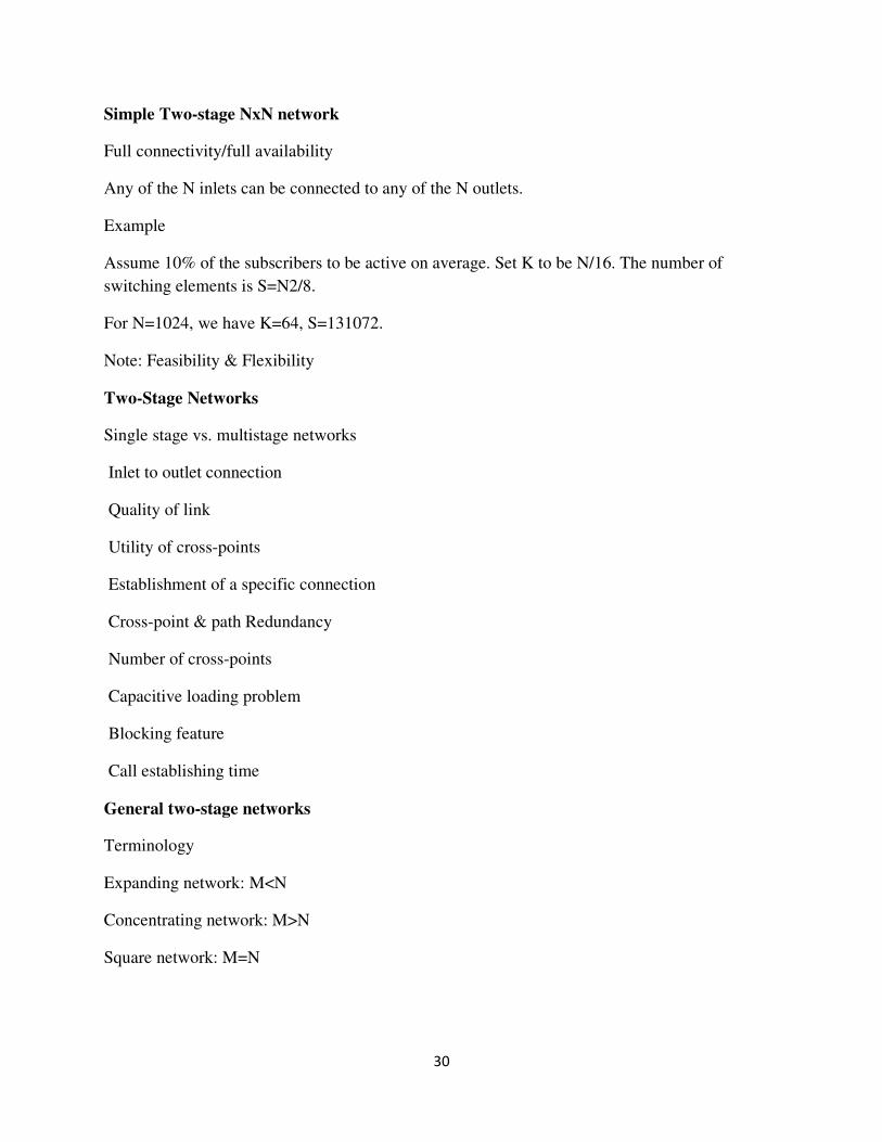
General two-stage networks
Terminology
Expanding network: M<N
Concentrating network: M>N
Square network: M=N
31
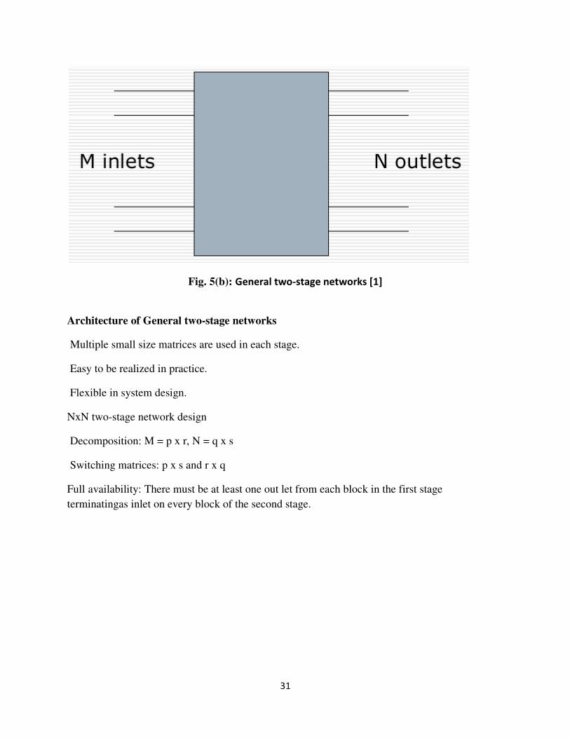
Fig. 5(b): General two-stage networks [1]
Architecture of General two-stage networks
Multiple small size matrices are used in each stage.
Easy to be realized in practice.
Flexible in system design.
NxN two-stage network design
Decomposition: M = p x r, N = q x s
Switching matrices: p x s and r x q
Full availability: There must be at least one out let from each block in the first stage
terminatingas inlet on every block of the second stage.
32
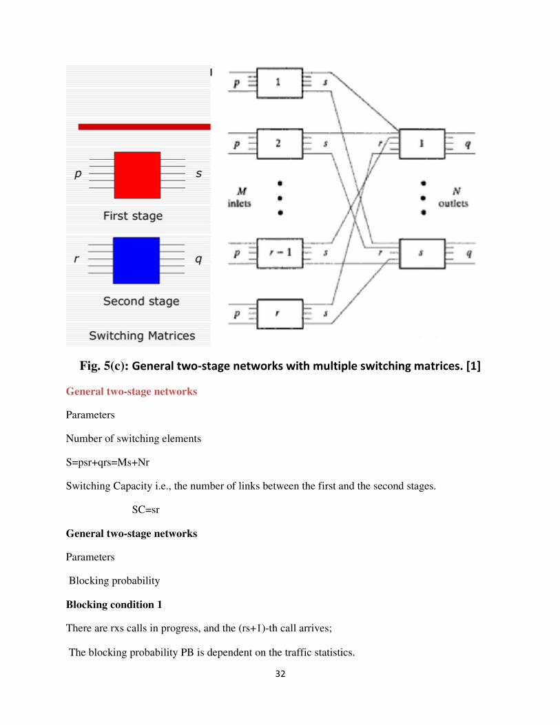
Fig. 5(c): General two-stage networks with multiple switching matrices. [1]
General two-stage networks
Parameters
Number of switching elements
S=psr+qrs=Ms+Nr
Switching Capacity i.e., the number of links between the first and the second stages.
SC=sr
General two-stage networks
Parameters
Blocking probability
Blocking condition 1
There are rxs calls in progress, and the (rs+1)-th call arrives;
The blocking probability PB is dependent on the traffic statistics.
33
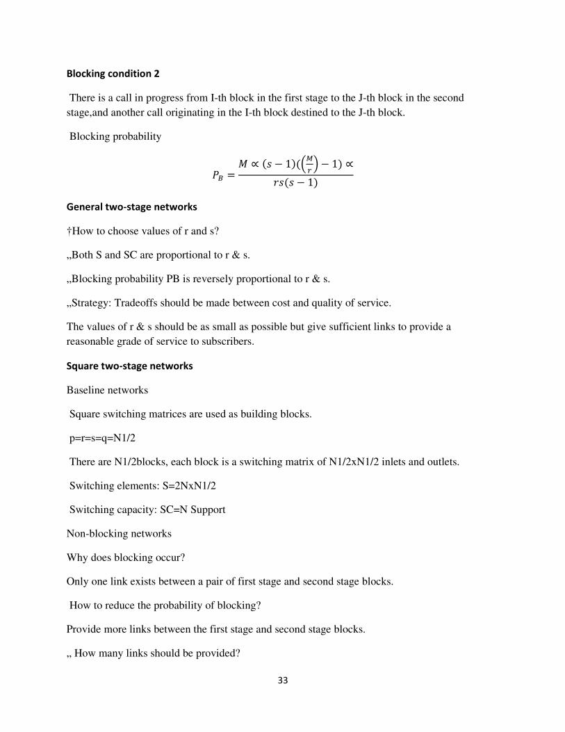
Blocking condition 2
There is a call in progress from I-th block in the first stage to the J-th block in the second
stage,and another call originating in the I-th block destined to the J-th block.
Blocking probability
�� =� ∝ �� − 1��� � − 1 ∝
���� − 1
General two-stage networks
†How to choose values of r and s?
„Both S and SC are proportional to r & s.
„Blocking probability PB is reversely proportional to r & s.
„Strategy: Tradeoffs should be made between cost and quality of service.
The values of r & s should be as small as possible but give sufficient links to provide a
reasonable grade of service to subscribers.
Square two-stage networks
Baseline networks
Square switching matrices are used as building blocks.
p=r=s=q=N1/2
There are N1/2blocks, each block is a switching matrix of N1/2xN1/2 inlets and outlets.
Switching elements: S=2NxN1/2
Switching capacity: SC=N Support
Non-blocking networks
Why does blocking occur?
Only one link exists between a pair of first stage and second stage blocks.
How to reduce the probability of blocking?
Provide more links between the first stage and second stage blocks.
„ How many links should be provided?
34
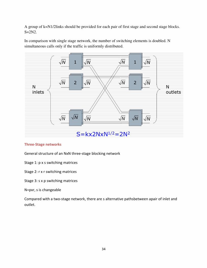
A group of k=N1/2links should be provided for each pair of first stage and second stage blocks.
S=2N2.
In comparison with single stage network, the number of switching elements is doubled. N
simultaneous calls only if the traffic is uniformly distributed.
Three-Stage networks
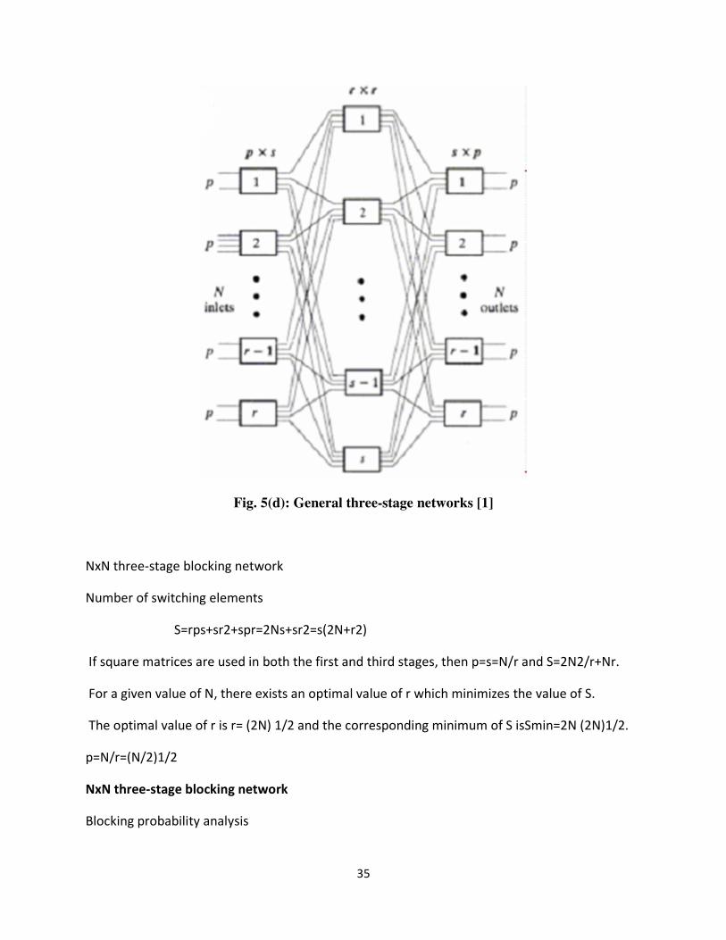
General structure of an NxN three-stage blocking network
Stage 1: p x s switching matrices
Stage 2: r x r switching matrices
Stage 3: s x p switching matrices
N=pxr, s is changeable
Compared with a two-stage network, there are s alternative pathsbetween apair of inlet and
outlet.
35
Fig. 5(d): General three-stage networks [1]
NxN three-stage blocking network
Number of switching elements
S=rps+sr2+spr=2Ns+sr2=s(2N+r2)
If square matrices are used in both the first and third stages, then p=s=N/r and S=2N2/r+Nr.
For a given value of N, there exists an optimal value of r which minimizes the value of S.
The optimal value of r is r= (2N) 1/2 and the corresponding minimum of S isSmin=2N (2N)1/2.
p=N/r=(N/2)1/2
NxN three-stage blocking network
Blocking probability analysis
36
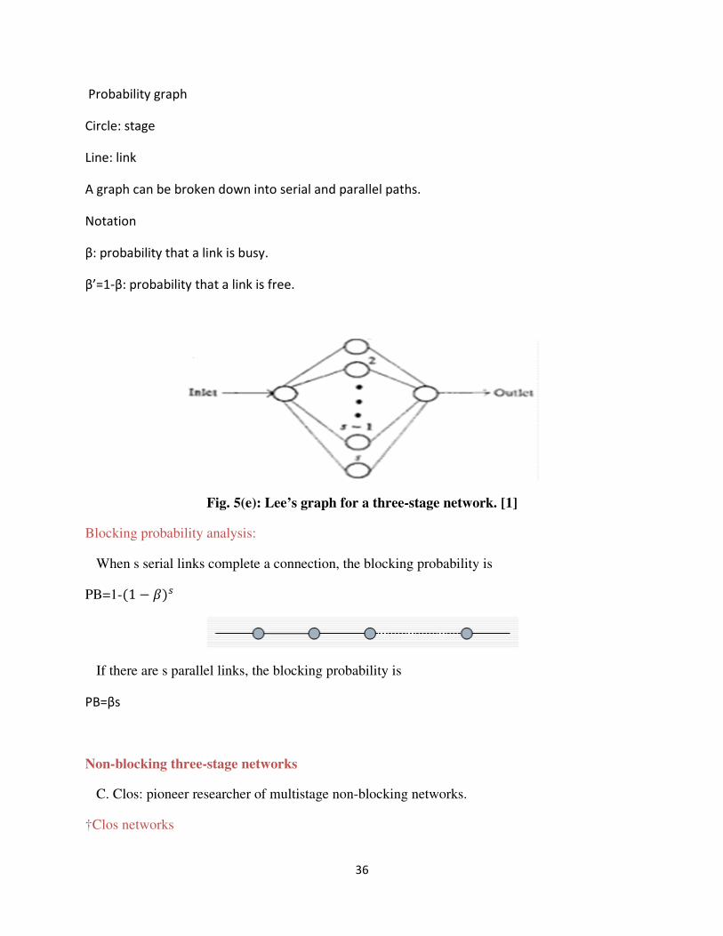
Probability graph
Circle: stage
Line: link
A graph can be broken down into serial and parallel paths.
Notation
β: probability that a link is busy.
β’=1-β: probability that a link is free.
Fig. 5(e): Lee’s graph for a three-stage network. [1]
Blocking probability analysis:
When s serial links complete a connection, the blocking probability is
PB=1-�1 − ��
If there are s parallel links, the blocking probability is
PB=βs
Non-blocking three-stage networks
C. Clos: pioneer researcher of multistage non-blocking networks.
†Clos networks
37
• Multistage non-blocking and fully available networks.
• Much less switching elements are used than that in single stage networks.
Design strategy
Providing adequate number of blocks in middle stages. For three-stage networks, the value of s
should be large enough.
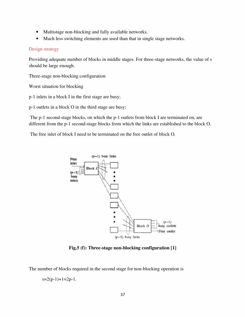
Three-stage non-blocking configuration
Worst situation for blocking
p-1 inlets in a block I in the first stage are busy;
p-1 outlets in a block O in the third stage are busy;
The p-1 second-stage blocks, on which the p-1 outlets from block I are terminated on, are
different from the p-1 second-stage blocks from which the links are established to the block O.
The free inlet of block I need to be terminated on the free outlet of block O.
Fig.5 (f): Three-stage non-blocking configuration [1]
The number of blocks required in the second stage for non-blocking operation is
s=2(p-1)+1=2p-1.
38
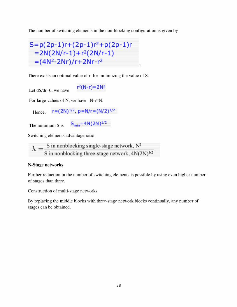
The number of switching elements in the non-blocking configuration is given by
†
There exists an optimal value of r for minimizing the value of S.
Let dS/dr=0, we have
For large values of N, we have N-r≈N.
Hence,
The minimum S is
Switching elements advantage ratio
N-Stage networks
Further reduction in the number of switching elements is possible by using even higher number
of stages than three.
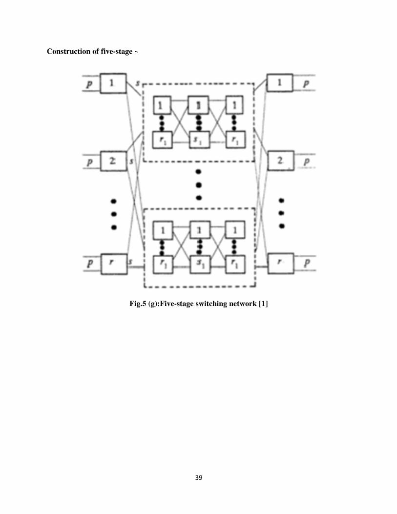
Construction of multi-stage networks
By replacing the middle blocks with three-stage network blocks continually, any number of
stages can be obtained.
39
Construction of five-stage ~
Fig.5 (g):Five-stage switching network [1]
40
10. Telecommunication Switching:
Various facilities of digital switching and transmission are the reason why the analog
switching is slowly getting replaced by digital switching. The incorporation of digital
switching and transmission technique into telecommunications altered the whole
telecommunication industries setup. The reliability of digital switching system is becoming
increasingly important for users of telephone services. Voice and/or data can be represented
using digital signals efficiently than analog signals.
A switching system is called digital when the input to and output from the switching system
can directly support digital signal. Many basic elements of the digital switching system and its
operation are very similar to the stored program control (SPC) switching system. The cost of
an analogue switch is roughly proportional to the number of cross points, but the cost
relationship in digital switching is different.
The functions of the digital switching network are to connect pairs of channels. So that
information arriving at the switching centre in a particular channel on one PCM multiplex
system can be passed to some other channel on an outgoing PCM multiplex systems. To
achieve this switching, two processes referred to as time switching and space switching are
used. The principles of these two switching process are described in this chapter.
In digital data communication (analog or digital signal), a fundamental requirement is that the
receiver should know the starting time and duration of each bit that it receives. To meet this
requirement a synchronous and synchronous transmission are used. These two transmission
techniques are described in this chapter.
Evolution of Digital Swtching System:
41
10.1 Evolution of Digital Switching System:
The early version of electronic switching system is the stored program control (SPC). The SPC
systems have temporary memory for storing transient call information and to carry programming
information. The SPC performs line control, trunk control, ancillary control, maintenance control
etc. The instructions required for performing these operations are resided in a single processor.
For reliability or high availability, the processor may be duplicated. Thus SPC uses centralized
software and hardware architectures.
A modern digital switching system employs a number of processors not uses distributed
software and hardware architectures. The digital switching system also referred as Electronic
Switching System–III generation is purely electronic in operation, the switching process is by
time division/digital transmission, the type of control is stored program common control and the
network uses pulse code modulation.
10.2 TIME DIVISION SWITCHING
Time division switching involves the sharing of cross points for shorter periods of time. This
paves way for the reassign of cross points and its associated circuits for other needed
connections. Therefore, in time division switching, greater savings in cross points can be
achieved. Hence, by using dynamic control mechanisms, a switching element can be assigned to
many inlet-outlet pairs for few microseconds. This is the principle of time division switching.
Time division switching uses time division multiplexing to achieve switching. Two popular
methods that are used in time division multiplexing are (a) the time slot interchange (TSI) and
(b) the TDM bus. In ordinary time division multiplexing, the data reaches the output in the same
order as they sent. But TSI changes the ordering of slots based on the desired connections. The
de-multiplexer separates the slots and passes them to the proper outputs. The TDM uses a control
unit. The control unit opens and closes the gates according to the switching need. The principle
of time division switching can be equally applied to analog and digital signals. For interfacing
sampled analog signals but not digitized, the analog time division switches are attractive. But for
larger switches, there are some limitations due to noise, distortion and crosstalk which normally
42
occurs in PAM signals. Thus analog switching is now used only in smaller switching systems. In
this section, the analog time division switching and digital time division switching are described
briefly.
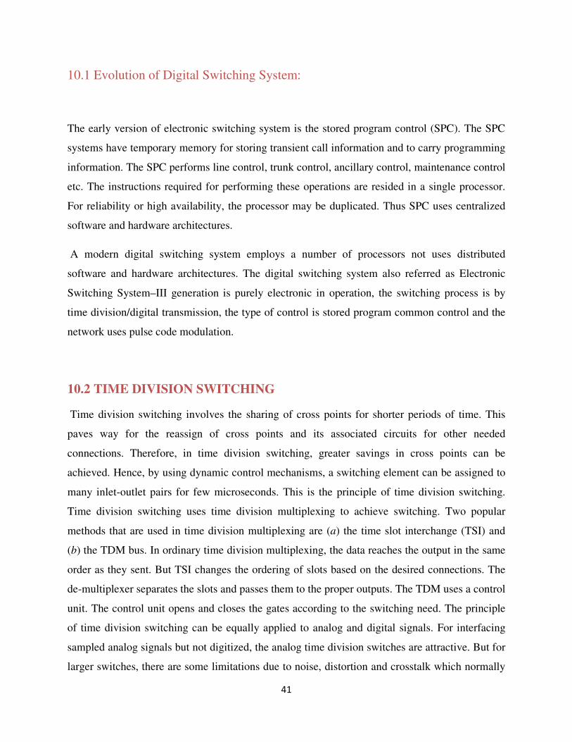
10.3 Analog Time Division Switching
Fig. 6 shows a simple analog time division switching structure. The speech is carried as PAM
analog samples or PCM digital samples, occurring at 125 µs intervals. When PAM samples are
switched in a time division manner, the switching is known as analog time division switching. If
PCM binary samples are switched, then the switching is known as digital time division
switching. A single switching bus supports a multiple number of connections by interleaving
PAM samples from receive line interfaces to transmit line interfaces. There are two cyclic
control stores. The first control store controls gating of inputs onto the bus one sample at a time.
The second control store operates in synchronism with the first and selects the appropriate output
line for each input sample.
Figure 6: Analog time division switching [1]
The selection of inlet/outlet is controlled by various ways. The (a) cyclic control and (b) memory based
control are the important controls and described in the following paragraphs.
43
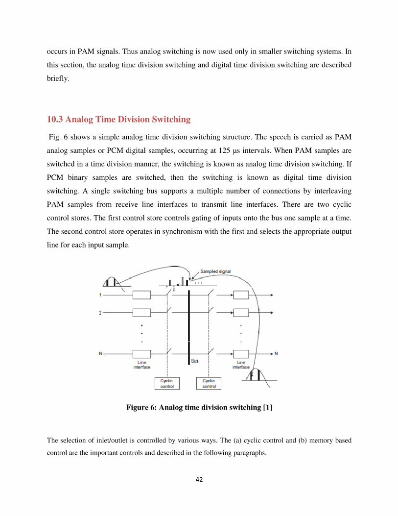
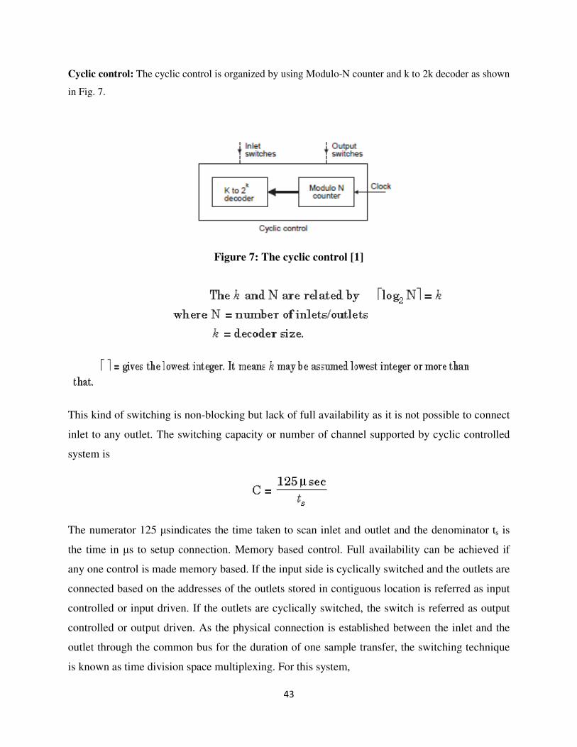
Cyclic control: The cyclic control is organized by using Modulo-N counter and k to 2k decoder as shown
in Fig. 7.
Figure 7: The cyclic control [1]
This kind of switching is non-blocking but lack of full availability as it is not possible to connect
inlet to any outlet. The switching capacity or number of channel supported by cyclic controlled
system is
The numerator 125 µsindicates the time taken to scan inlet and outlet and the denominator ts is
the time in µs to setup connection. Memory based control. Full availability can be achieved if
any one control is made memory based. If the input side is cyclically switched and the outlets are
connected based on the addresses of the outlets stored in contiguous location is referred as input
controlled or input driven. If the outlets are cyclically switched, the switch is referred as output
controlled or output driven. As the physical connection is established between the inlet and the
outlet through the common bus for the duration of one sample transfer, the switching technique
is known as time division space multiplexing. For this system,
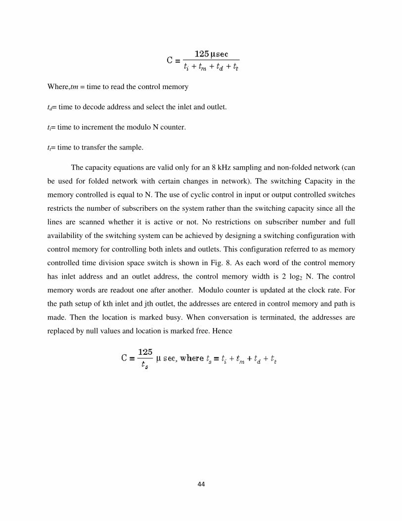
44
Where,tm = time to read the control memory
td= time to decode address and select the inlet and outlet.
ti= time to increment the modulo N counter.
tt= time to transfer the sample.
The capacity equations are valid only for an 8 kHz sampling and non-folded network (can
be used for folded network with certain changes in network). The switching Capacity in the
memory controlled is equal to N. The use of cyclic control in input or output controlled switches
restricts the number of subscribers on the system rather than the switching capacity since all the
lines are scanned whether it is active or not. No restrictions on subscriber number and full
availability of the switching system can be achieved by designing a switching configuration with
control memory for controlling both inlets and outlets. This configuration referred to as memory
controlled time division space switch is shown in Fig. 8. As each word of the control memory
has inlet address and an outlet address, the control memory width is 2 log2 N. The control
memory words are readout one after another. Modulo counter is updated at the clock rate. For
the path setup of kth inlet and jth outlet, the addresses are entered in control memory and path is
made. Then the location is marked busy. When conversation is terminated, the addresses are
replaced by null values and location is marked free. Hence
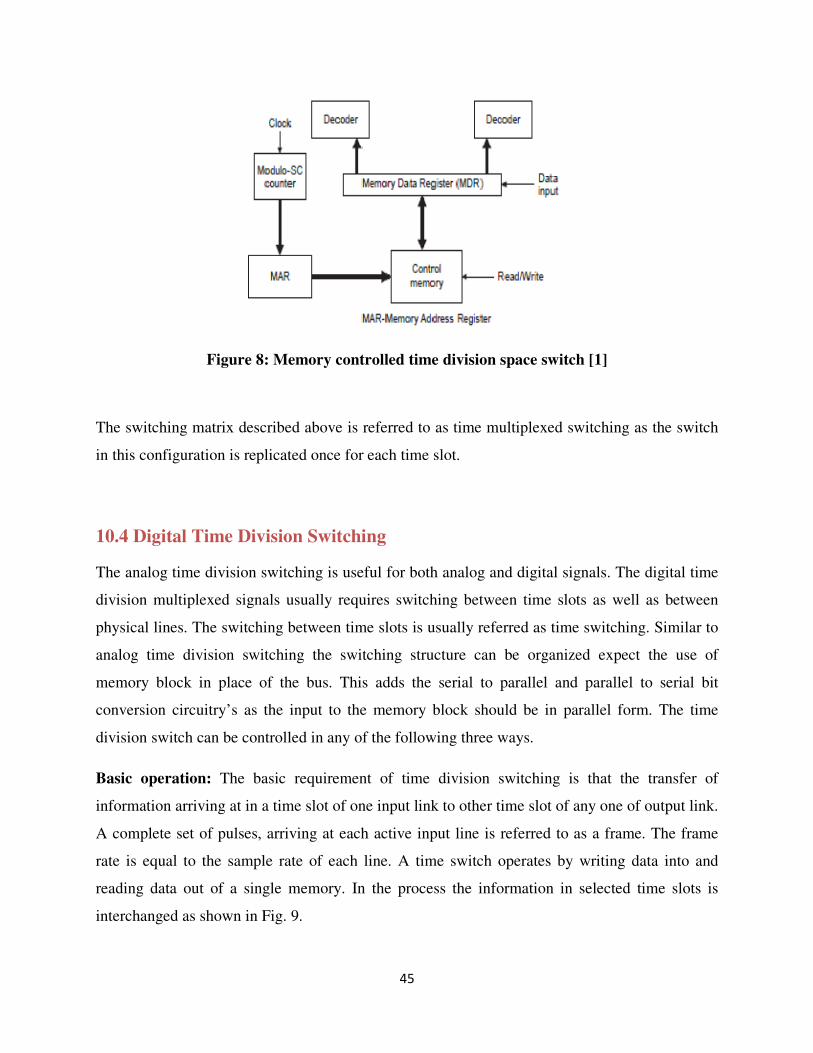
45
Figure 8: Memory controlled time division space switch [1]
The switching matrix described above is referred to as time multiplexed switching as the switch
in this configuration is replicated once for each time slot.
10.4 Digital Time Division Switching
The analog time division switching is useful for both analog and digital signals. The digital time
division multiplexed signals usually requires switching between time slots as well as between
physical lines. The switching between time slots is usually referred as time switching. Similar to
analog time division switching the switching structure can be organized expect the use of
memory block in place of the bus. This adds the serial to parallel and parallel to serial bit
conversion circuitry’s as the input to the memory block should be in parallel form. The time
division switch can be controlled in any of the following three ways.
Basic operation: The basic requirement of time division switching is that the transfer of
information arriving at in a time slot of one input link to other time slot of any one of output link.
A complete set of pulses, arriving at each active input line is referred to as a frame. The frame
rate is equal to the sample rate of each line. A time switch operates by writing data into and
reading data out of a single memory. In the process the information in selected time slots is
interchanged as shown in Fig. 9.
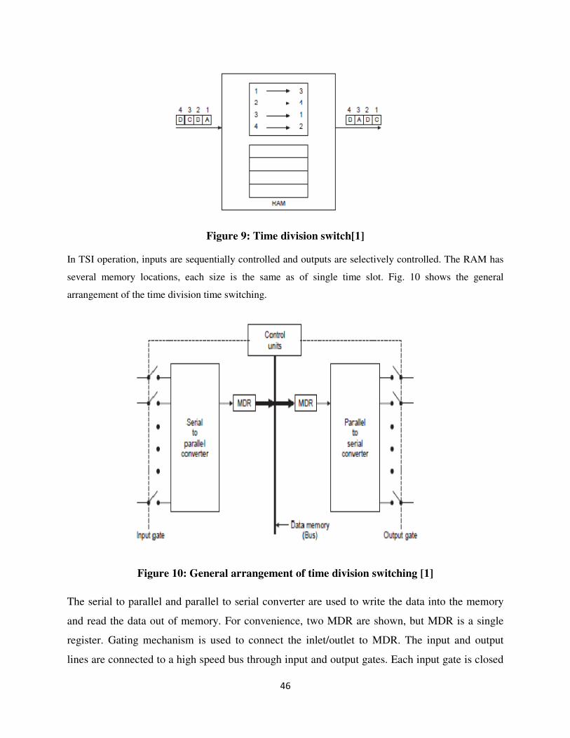
46
Figure 9: Time division switch[1]
In TSI operation, inputs are sequentially controlled and outputs are selectively controlled. The RAM has
several memory locations, each size is the same as of single time slot. Fig. 10 shows the general
arrangement of the time division time switching.
Figure 10: General arrangement of time division switching [1]
The serial to parallel and parallel to serial converter are used to write the data into the memory
and read the data out of memory. For convenience, two MDR are shown, but MDR is a single
register. Gating mechanism is used to connect the inlet/outlet to MDR. The input and output
lines are connected to a high speed bus through input and output gates. Each input gate is closed

47
during one of the four time slots. During the same time slot, only one output gate closed. This
pair of gates allows a burst of data to be transferred from one input line to a specific output line
through the bus. The control unit opens and closes the gates according to switching need. The
time division time switch may be controlled by sequential write/random read or random write/
sequential read. Fig. 10 depicts both modes of operation and indicateshow the memories are
accessed to translate information from time slot 2 to time slot 16. Both methods use a cyclic
control.
Fig. 10 (a) implies that specific memory locations are dedicated to respective channels of the
incoming TDM link. Data are stored in sequential locations in memory by incrementing modulo
N counter with every time slot. Thus incoming data during time slot 2 is stored in the second
location within the memory. On output, information retrieved from the control store specifies
which address is to be accessed for that particular time slot. Thus sixteenth word of control store
contains the number 2, implying that the contents of data store address 2 is transferred to the
output link during outgoing slot 16. Random write/sequential read mode of operation is opposite
to that of sequential write/ random read. Incoming data are written into the memory locations as
specified by the control store, but outgoing data are retrieved sequentially under control of an
outgoing time slot counter. The data received during time slot 2 is written directly into data store
address 16 and it is retrieved during outgoing TDM channel number 16.
Figure 10 (a) : Memory locations allocated to TDM [1]
48
10.5 TWO DIMENSIONAL DIGITAL SWITCHING
Combination of the time and space switches leads to a configuration that achieved both time slot
interchange and sample switching across trunks. These structures also permit a large number of
simultaneous connections to be supported for a given technology. Large digital switches require
switching operations in both a space dimension and a time dimension. There are a large variety
of network configurations that can be used to accomplish these requirements. The incoming and
outgoing PCM highways are spatially separate. So the connection of one line of local exchange
obviously requires space switching to connect to the channel of outgoing highways. Thus the
switching network must be able to receive PCM samples from one time slot and retransmit them
in a different time-slot. This is known as time slot interchange, or simply as time switching. Thus
the switching network must perform both space and time switching.
The space switching and time switching may be accomplished in many ways. A two stage
combination switch may be organized with time switch as first stage and the space switch as the
second stage or vice versa. The resulting configurations are referred as time space (TS) or space
time (ST) switches respectively. Three stage time and space combinations of TST and STS
configurations are more popular and flexible. Very large division switches includes many
combinations of time and space switches. Typical configurations are TSST, TSSSST, and
TSTSTSTS. These switches support 40000 lines or more economically. The general block
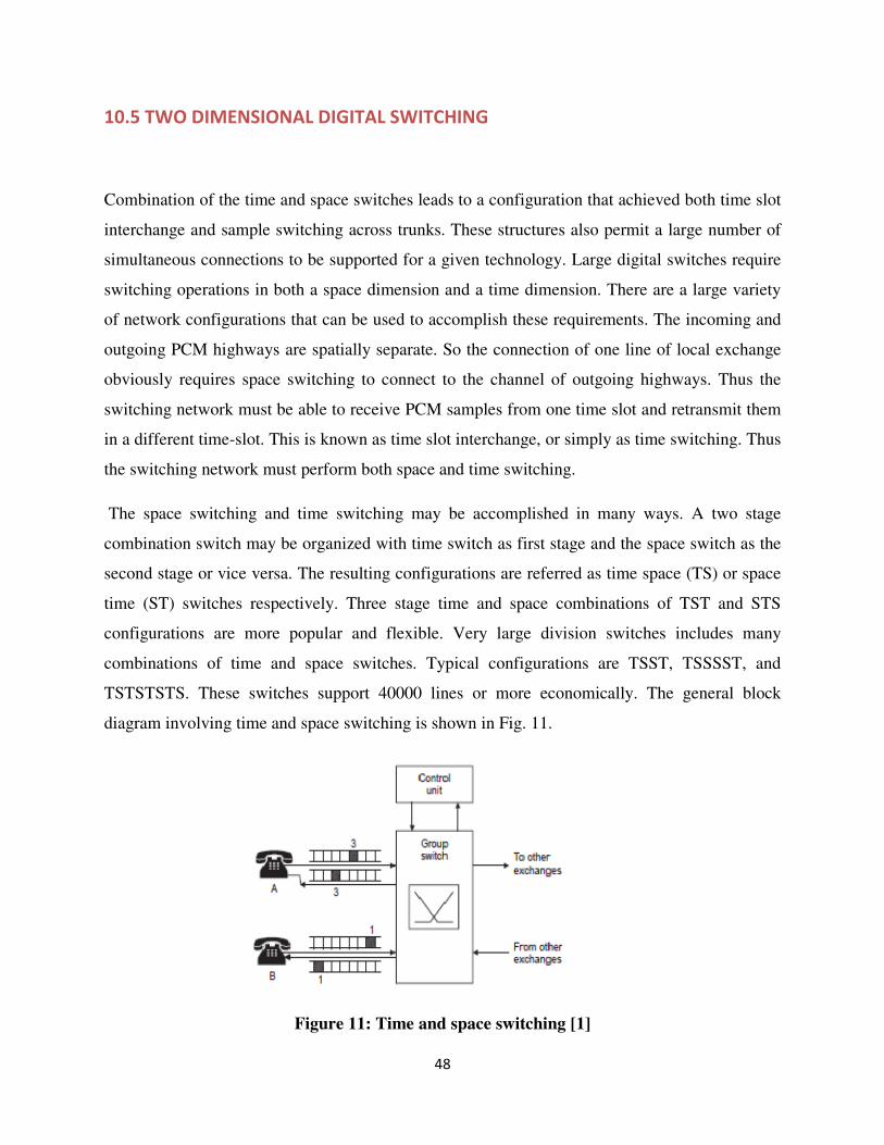
diagram involving time and space switching is shown in Fig. 11.
Figure 11: Time and space switching [1]
49
The main task of the switching part is to interconnect an incoming time slot and an outgoing
time slot. The unit responsible for this function is group switch. There are two types of building
block in the digital group switch. They are time switch and space switch. In Fig. 7, the subscriber
makes a local call to B. The control unit has assigned time slot 3 to the call on its way into the
group switch, and time slot 1 on its way out of the group switch (to B). This is maintained during
the entire call. Similarly B to A also carried out. The fundamental design and structure of the two
switches viz. time switch and space switch are described in the following sections.
11. Space and Time Switches
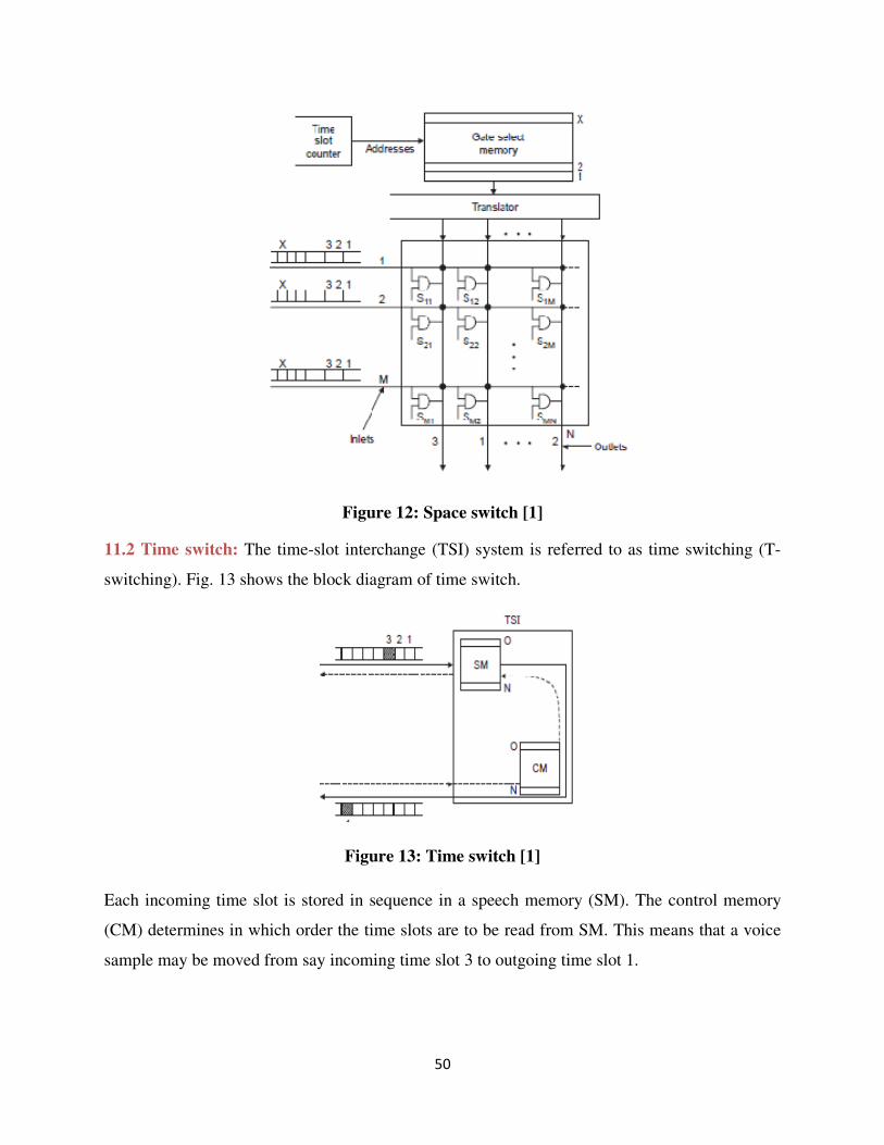
11.1 Space switch: Fig. 12 shows a typical space switch. It uses a space array to provide
switching generally the space switch consists of a matrix of M × N switching points where M is
number of inlets and N is number of outlets. A connection between an inlet and an outlet is made
by the simple logic gates (AND gates). As logic gates are unidirectional, two paths through
switching matrix must be established to accommodate a two way conversation. The logic gate
array can serve for concentration, expansion or distribution depending on M is larger, smaller or
equal to N. Fig. 8 shows only one voice direction. However, the corresponding components are
available for the opposite direction too. A number of M, of X slot multiplexers, provide the
inputs and the outlets are connected to N, X slot de-multiplexers. The gate select memory has X
locations. The word containing information about which cross point is to be enabled is decoded
by the translator. During each internal time slot, one cross point is activated. In the shift to the
next interval time slot, the control memory is incremented by one step, and a new cross point
pattern is formed in the matrix.
50
Figure 12: Space switch [1]
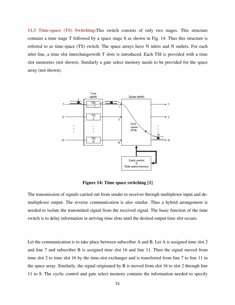
11.2 Time switch: The time-slot interchange (TSI) system is referred to as time switching (T-
switching). Fig. 13 shows the block diagram of time switch.
Figure 13: Time switch [1]
Each incoming time slot is stored in sequence in a speech memory (SM). The control memory
(CM) determines in which order the time slots are to be read from SM. This means that a voice
sample may be moved from say incoming time slot 3 to outgoing time slot 1.
51
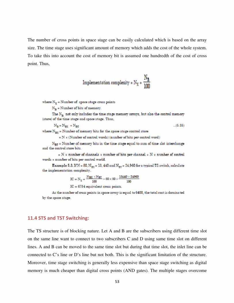
11.3 Time-space (TS) Switching:This switch consists of only two stages. This structure
contains a time stage T followed by a space stage S as shown in Fig. 14. Thus this structure is
referred to as time-space (TS) switch. The space arrays have N inlets and N outlets. For each
inlet line, a time slot interchangerwith T slots is introduced. Each TSI is provided with a time
slot memories (not shown). Similarly a gate select memory needs to be provided for the space
array (not shown).
Figure 14: Time space switching [1]
The transmission of signals carried out from sender to receiver through multiplexer input and de-
multiplexer output. The reverse communication is also similar. Thus a hybrid arrangement is
needed to isolate the transmitted signal from the received signal. The basic function of the time
switch is to delay information in arriving time slots until the desired output time slot occurs.
Let the communication is to take place between subscriber A and B. Let A is assigned time slot 2
and line 7 and subscriber B is assigned time slot 16 and line 11. Then the signal moved from
time slot 2 to time slot 16 by the time-slot exchanger and is transferred from line 7 to line 11 in
the space array. Similarly, the signal originated by B is moved from slot 16 to slot 2 through line
11 to 8. The cyclic control and gate select memory contains the information needed to specify

52
the space stage configuration for each individual time slot of a frame. The time stage has to
provide decays ranging from one time slot to a full frame. During each outgoing time slot,
control information is accessed that specifies inter stage link number to output link. During other
time slots, the space switch is completely reconfigured to support other connections.
Let each time slot interchanger have T slots. If the space array is a N × N, then the simultaneous
connections possible is NT. If T = 128 and N = 16, 2048 connections can be supported. This
structure is not free of blocking. The control store is a parallel end around shift resister. If space
array is at the inlet side and time switch is at the output side, the structure is referred as space
time (ST) switching. Both TS and ST arrangements are equally effective. TS system is used in
DMS 100 digital switching system developed in Canada (1979). It handles 61000 trunks and
accommodates 39000 trunks.
53
The number of cross points in space stage can be easily calculated which is based on the array
size. The time stage uses significant amount of memory which adds the cost of the whole system.
To take this into account the cost of memory bit is assumed one hundredth of the cost of cross
point. Thus,
11.4 STS and TST Switching:
The TS structure is of blocking nature. Let A and B are the subscribers using different time slot
on the same line want to connect to two subscribers C and D using same time slot on different
lines. A and B can be moved to the same time slot but during that time slot, the inlet line can be
connected to C’s line or D’s line but not both. This is the significant limitation of the structure.
Moreover, time stage switching is generally less expensive than space stage switching as digital
memory is much cheaper than digital cross points (AND gates). The multiple stages overcome
54
the limitations of the individual switches and cost savings can also be achieved. TST, STS,
TSST, TSSSST and TSTSTSTSTSTSTS are the switching system configurations used in digital
switching system. However, the TST structure is the most common.
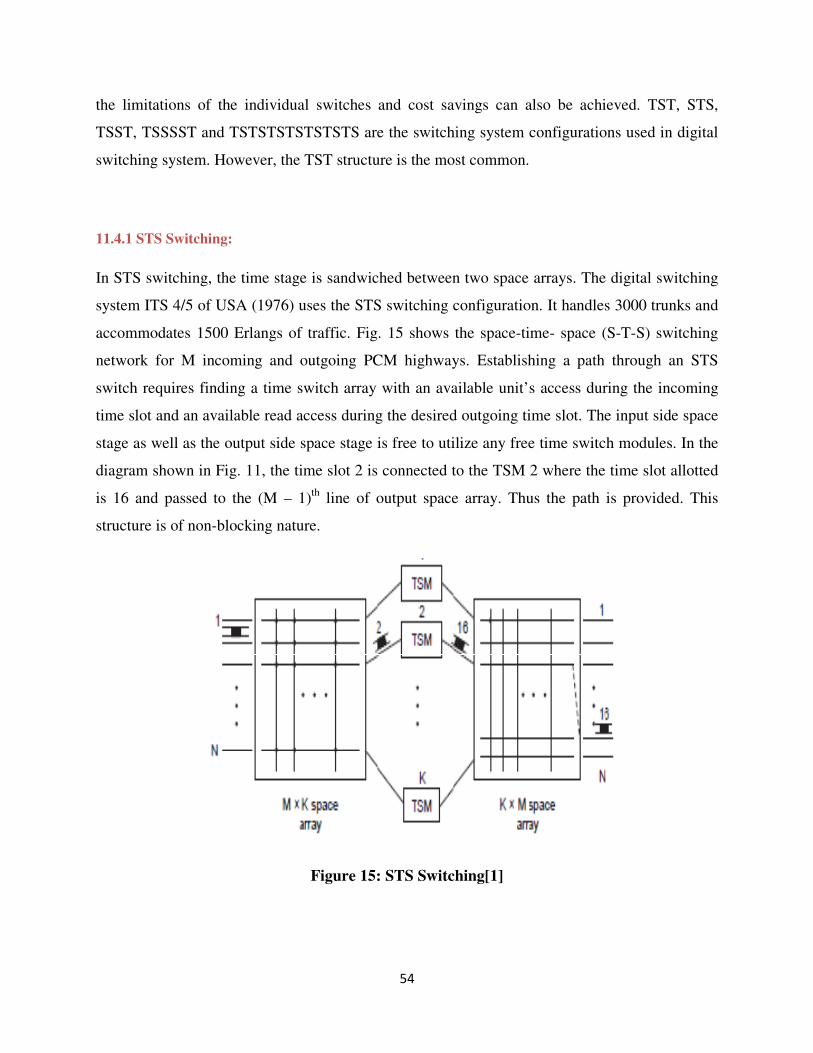
11.4.1 STS Switching:
In STS switching, the time stage is sandwiched between two space arrays. The digital switching
system ITS 4/5 of USA (1976) uses the STS switching configuration. It handles 3000 trunks and
accommodates 1500 Erlangs of traffic. Fig. 15 shows the space-time- space (S-T-S) switching
network for M incoming and outgoing PCM highways. Establishing a path through an STS
switch requires finding a time switch array with an available unit’s access during the incoming
time slot and an available read access during the desired outgoing time slot. The input side space
stage as well as the output side space stage is free to utilize any free time switch modules. In the
diagram shown in Fig. 11, the time slot 2 is connected to the TSM 2 where the time slot allotted
is 16 and passed to the (M – 1)th
line of output space array. Thus the path is provided. This
structure is of non-blocking nature.
Figure 15: STS Switching[1]
55
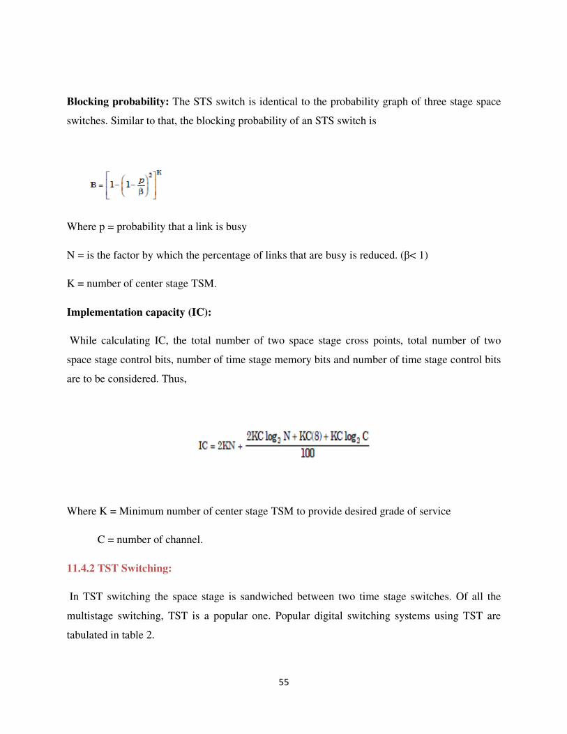
Blocking probability: The STS switch is identical to the probability graph of three stage space
switches. Similar to that, the blocking probability of an STS switch is
Where p = probability that a link is busy
N = is the factor by which the percentage of links that are busy is reduced. (β< 1)
K = number of center stage TSM.
Implementation capacity (IC):
While calculating IC, the total number of two space stage cross points, total number of two
space stage control bits, number of time stage memory bits and number of time stage control bits
are to be considered. Thus,
Where K = Minimum number of center stage TSM to provide desired grade of service
C = number of channel.
11.4.2 TST Switching:
In TST switching the space stage is sandwiched between two time stage switches. Of all the
multistage switching, TST is a popular one. Popular digital switching systems using TST are
tabulated in table 2.
56
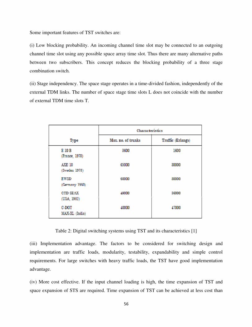
Some important features of TST switches are:
(i) Low blocking probability. An incoming channel time slot may be connected to an outgoing
channel time slot using any possible space array time slot. Thus there are many alternative paths
between two subscribers. This concept reduces the blocking probability of a three stage
combination switch.
(ii) Stage independency. The space stage operates in a time-divided fashion, independently of the
external TDM links. The number of space stage time slots L does not coincide with the number
of external TDM time slots T.
Table 2: Digital switching systems using TST and its characteristics [1]
(iii) Implementation advantage. The factors to be considered for switching design and
implementation are traffic loads, modularity, testability, expandability and simple control
requirements. For large switches with heavy traffic loads, the TST have good implementation
advantage.
(iv) More cost effective. If the input channel loading is high, the time expansion of TST and
space expansion of STS are required. Time expansion of TST can be achieved at less cost than
57
space expansion of STS. In comparison with STS, the TST have certain limitations. For small
switches, the STS architectures are less complex to implement than TST. The control
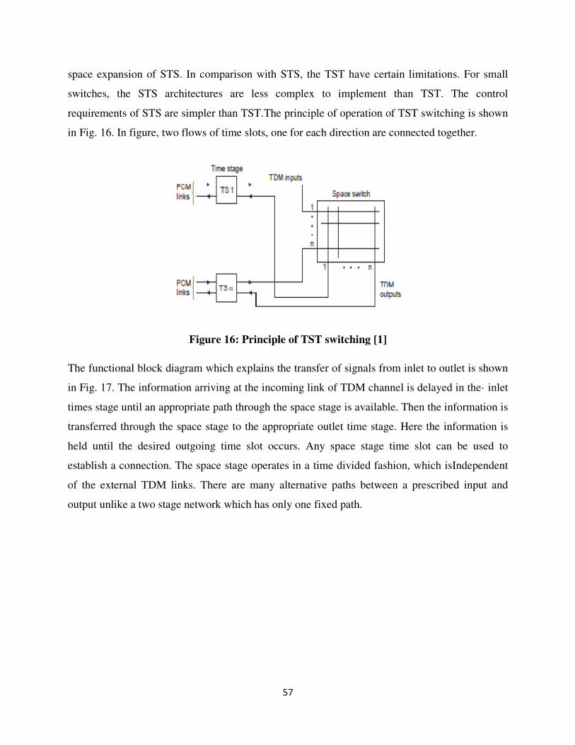
requirements of STS are simpler than TST.The principle of operation of TST switching is shown
in Fig. 16. In figure, two flows of time slots, one for each direction are connected together.
Figure 16: Principle of TST switching [1]
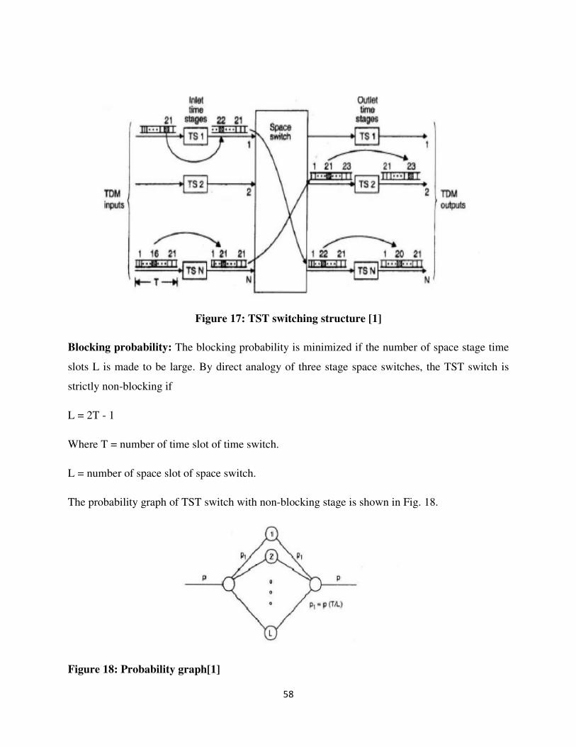
The functional block diagram which explains the transfer of signals from inlet to outlet is shown
in Fig. 17. The information arriving at the incoming link of TDM channel is delayed in the· inlet
times stage until an appropriate path through the space stage is available. Then the information is
transferred through the space stage to the appropriate outlet time stage. Here the information is
held until the desired outgoing time slot occurs. Any space stage time slot can be used to
establish a connection. The space stage operates in a time divided fashion, which isIndependent
of the external TDM links. There are many alternative paths between a prescribed input and
output unlike a two stage network which has only one fixed path.
58
Figure 17: TST switching structure [1]
Blocking probability: The blocking probability is minimized if the number of space stage time
slots L is made to be large. By direct analogy of three stage space switches, the TST switch is
strictly non-blocking if
L = 2T - 1
Where T = number of time slot of time switch.
L = number of space slot of space switch.
The probability graph of TST switch with non-blocking stage is shown in Fig. 18.
Figure 18: Probability graph[1]
59
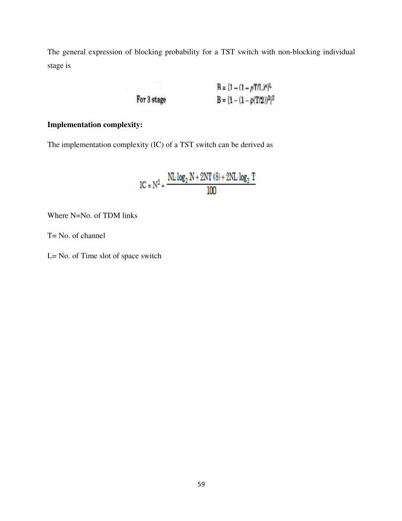
The general expression of blocking probability for a TST switch with non-blocking individual
stage is
Implementation complexity:
The implementation complexity (IC) of a TST switch can be derived as
Where N=No. of TDM links
T= No. of channel
L= No. of Time slot of space switch
60
Objective of the Module- II:
• What is traffic network load?
• What is the meaning of blocking probability and its
physical significance in the telecommunication
network?
• What is grade of service?
• Difference between the grade of service and the
blocking probability.
• Markov Model of a switching system in a
telecommunication network.
• Traffic arrival and service time probability density
function
• Design of blocking model and delay model
• Estimation of call loss in a blocking model and in a
delay model.
• Design of a subscriber loop system
• Different types of signaling techniques that are used in a
telecommunication network.
• Routing protocol used in a telecommunication network.
• Switching hierarchy in a telecommunication network.
61
MODULE-II
12. TRAFFIC ENGINEERING:
Due to the non-availability of switching paths blocking of a subscriber call will occur. For this
we have calculated blocking probabilities as discussed in the previous chapters [1]. These
problems can be avoided by the help of traffic engineering. Traffic engineering analysis enables
one to determine the ability of a telecommunication network to carry a given traffic at a
particular loss probability [1].
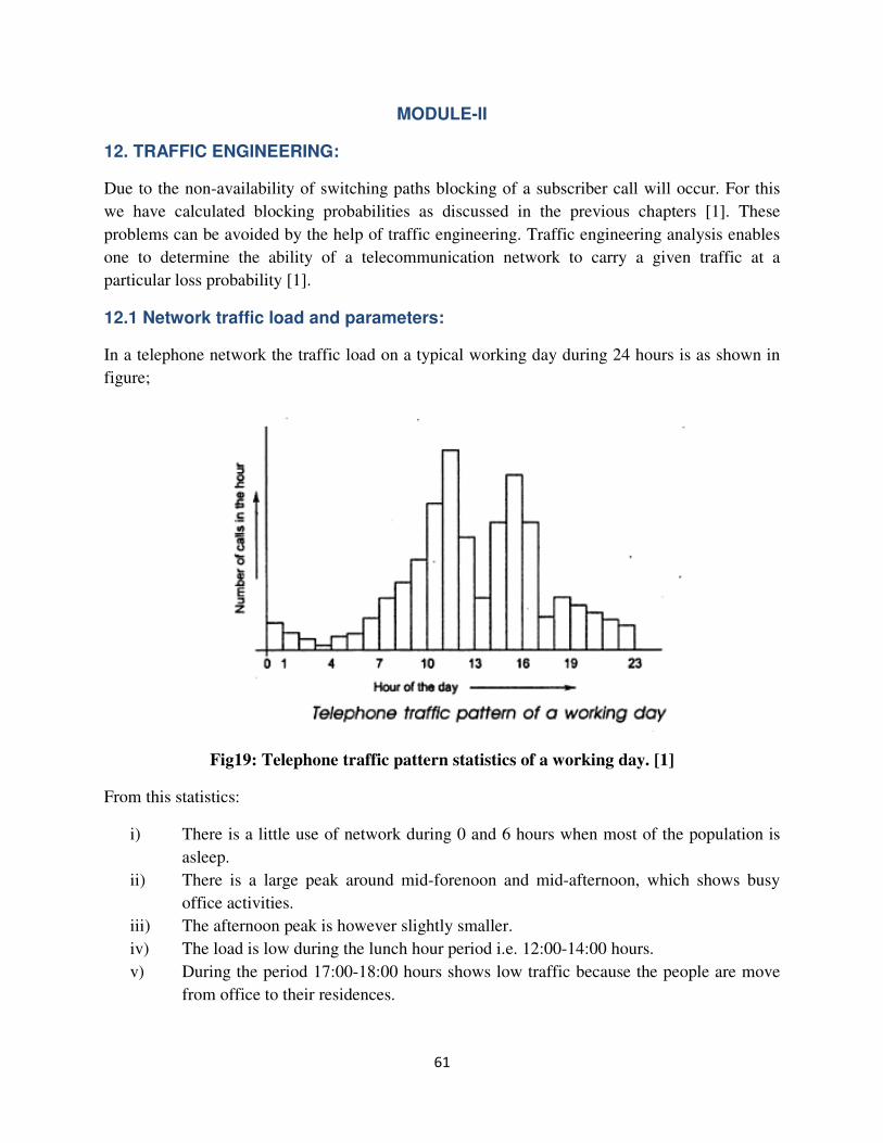
12.1 Network traffic load and parameters:
In a telephone network the traffic load on a typical working day during 24 hours is as shown in
figure;
Fig19: Telephone traffic pattern statistics of a working day. [1]
From this statistics:
i) There is a little use of network during 0 and 6 hours when most of the population is
asleep.
ii) There is a large peak around mid-forenoon and mid-afternoon, which shows busy
office activities.
iii) The afternoon peak is however slightly smaller.
iv) The load is low during the lunch hour period i.e. 12:00-14:00 hours.
v) During the period 17:00-18:00 hours shows low traffic because the people are move
from office to their residences.
62
vi) The peak of domestic calls occurs after 18:00 hours when person reach home and
reduces tariff applies.
vii) During holidays and festival days the traffic pattern is different.
Generally there is a peak of calls occurs around 10:00 hours just before people leave their homes
on outings and another peak occur in the evening when people returns to their home.
There are 3 types of busy hours are defined by CCITT:
1) BUSY HOUR: In a day the 60 minute interval in which the traffic is the highest is called
the busy hour.
2) PEAK BUSY HOUR: The busy hour on each day is called peak busy hour; It varies
from day to day or over a number of days.
3) TIME CONSISTENT BUSY HOUR: The one hour period starting at the same time
each day for which the number of call attempts is greatest over the days.
Again all the call attempts are not materialize into actual conversations for variety of reasons:
Those are due to called line busy, no answers from called lines, and blocking in the trunk
groups or the switching centers [1].
A call attempt is said to be successful or completed if the party answers, successful call
attempts is again categorized into three types: [1]
1. CCR (call completion rate): It is defined as the number of successful calls to the
number of call attempts.
2. BHCA (busy hour call attempts): The number of call attempts in the busy hour is called
busy hour call attempts.
13. GRADE OF SERVICE AND BLOCKING PROBABILITY:
1. The amount of traffic rejected by the network is an quality of service offered by the
network, This is known as grade of service.[2]
2. Grade of service is defined as the ratio of lost traffic to offered traffic.
3. The smaller is the value of grade of service, the better is the service.
63
4. The blocking probability PB is defined as the probability that all the servers in a system
are busy.
5. When all the servers are busy no further traffic can be carried by the system and the
arriving subscriber traffic is blocked.
13.1 DIFFERENCE BETWEEN GOS AND PB
1. Grade of service is also known as call congestion or loss probability where as blocking
probability is otherwise known as time congestion.[2]
2. GOS is a measure from the subscriber point of view i.e. the GOS is zero as there is
always a server available to a subscriber where as blocking probability is a measure from
the network or switching system point of view i.e. the blocking probability is non zero as
there is a definite probability that all the servers are busy at a given instant.
3. GOS is arrived by observing the number of rejected subscriber calls where as PB is
arrived by observing the busy servers in the switching system.
13.2 DELAY PROBABILITY:
If the offered load or the input rate of traffic far exceeds the network capacity, then the queue
lengths become very large and the calls have undesirably long delay. The probability that the
call experiences a delay termed as delay probability [2]. In this case the delay systems are
said to be unstable as they would never be able to clear the load.
The technique of queued up traffic cleared to an acceptable limit to maintain a stable
operation is called flow control.[1]
13.3 MODELLING SWITCHING SYSTEMS:
In a telecommunication network the call generation by the subscribers and the behavior of
the network or the switching system are random process [1] . A random process or a
stochastic process is one in which one or more quantities vary with time such that the
instantaneous variables predictable with certain probability.
We have four different types of stochastic process namely
i. Continuous time continuous state
ii. Continuous time discrete state
iii. Discrete time continuous state
iv. Discrete time discrete state
A discrete state stochastic process is called chain.
Random processes whose statistical parameters do not change with time are known as
stationary process [1].
64
The random processes which have identical time and ensemble averages are known as
ergodic process [1].
In random process if the mean and variance alone are stationary and other higher order
moments may vary with time are known as wide sense stationary process [1].
13.4 MARKOV PROCESS:
Markov process is an important class of random processes that have some special properties.
The properties were defined by A.A Markov in1907.This property is used for modeling of
our switching system [2].
A discrete time markov chain i.e. discrete time discrete state Markov process is defined as
The above equation states that the entire past history (n-1,n-2,n-3) is summarized in its
current status (n),hence the next state (n+1) is determined only by the current state [2].
The interstate transition time in a discrete time markov process is geometrically distributed
and in a continuous time markov process it is exponentially distributed [1].
13.4.1 BIRTH-DEATH PROCESS:
The birth and death process is a special case of the discrete state continuous time Markov
process, which is often called a continuous-time Markov chain. The number of calls in
progress is always between 0 and N. It thus has N + 1 state. If the Markov chain can occur
only to adjacent states (i.e. probability change from each state to the one above and one
below it) the process is known as birth-death (B–D) process [2].
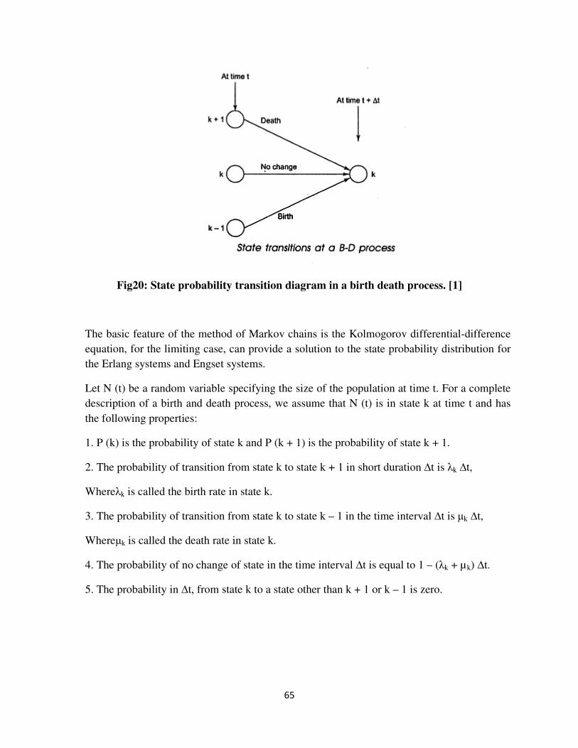
65
Fig20: State probability transition diagram in a birth death process. [1]
The basic feature of the method of Markov chains is the Kolmogorov differential-difference
equation, for the limiting case, can provide a solution to the state probability distribution for
the Erlang systems and Engset systems.
Let N (t) be a random variable specifying the size of the population at time t. For a complete
description of a birth and death process, we assume that N (t) is in state k at time t and has
the following properties:
1. P (k) is the probability of state k and P (k + 1) is the probability of state k + 1.
2. The probability of transition from state k to state k + 1 in short duration ∆t is λk ∆t,
Whereλk is called the birth rate in state k.
3. The probability of transition from state k to state k – 1 in the time interval ∆t is µk ∆t,
Whereµk is called the death rate in state k.
4. The probability of no change of state in the time interval ∆t is equal to 1 – (λk + µk) ∆t.
5. The probability in ∆t, from state k to a state other than k + 1 or k – 1 is zero.
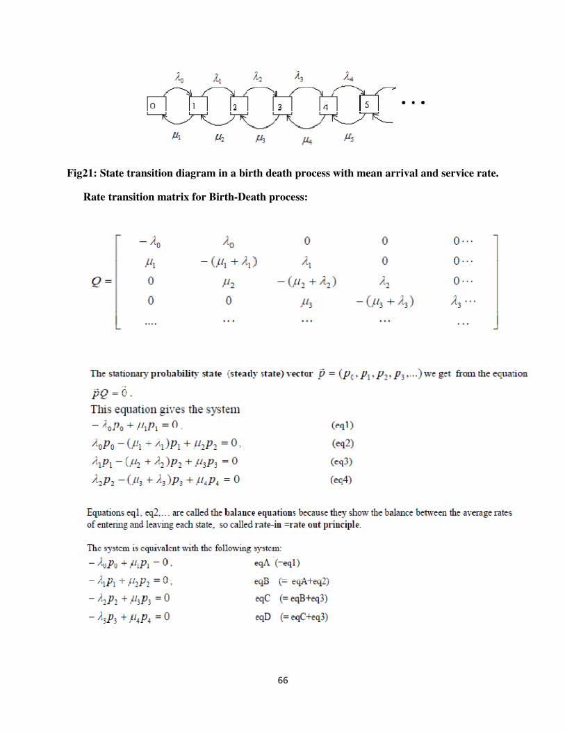
66
Fig21: State transition diagram in a birth death process with mean arrival and service rate.
Rate transition matrix for Birth-Death process:
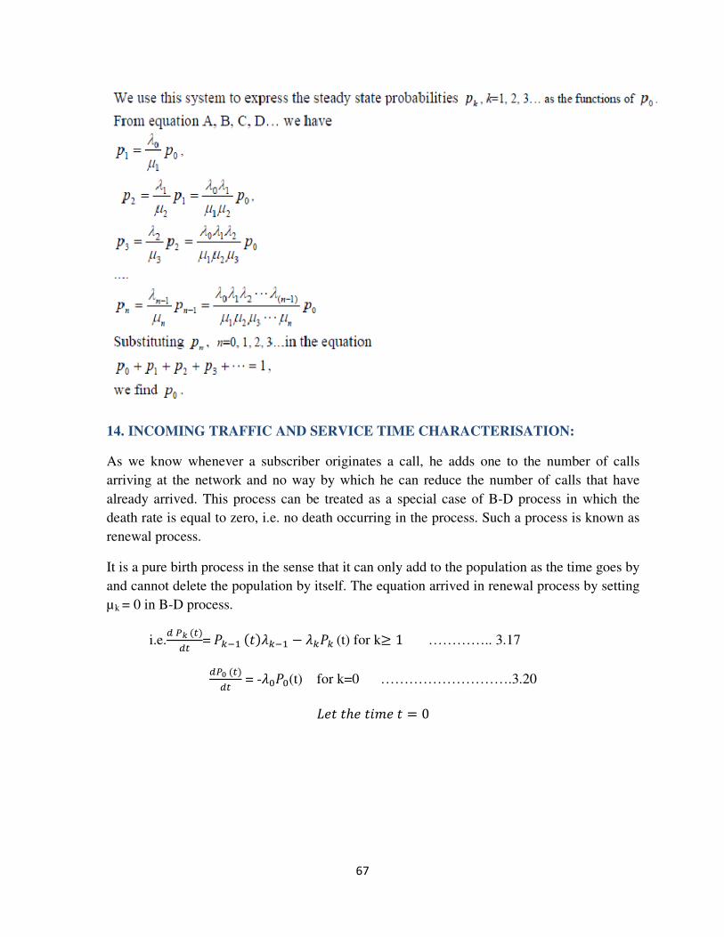
67
14. INCOMING TRAFFIC AND SERVICE TIME CHARACTERISATION:
As we know whenever a subscriber originates a call, he adds one to the number of calls
arriving at the network and no way by which he can reduce the number of calls that have
already arrived. This process can be treated as a special case of B-D process in which the
death rate is equal to zero, i.e. no death occurring in the process. Such a process is known as
renewal process.
It is a pure birth process in the sense that it can only add to the population as the time goes by
and cannot delete the population by itself. The equation arrived in renewal process by setting
µk = 0 in B-D process.
i.e.�����
�� =���������� − ����(t) for k≥ 1 ………….. 3.17
������� = -����(t) for k=0 ……………………….3.20
� ��ℎ �"# � = 0
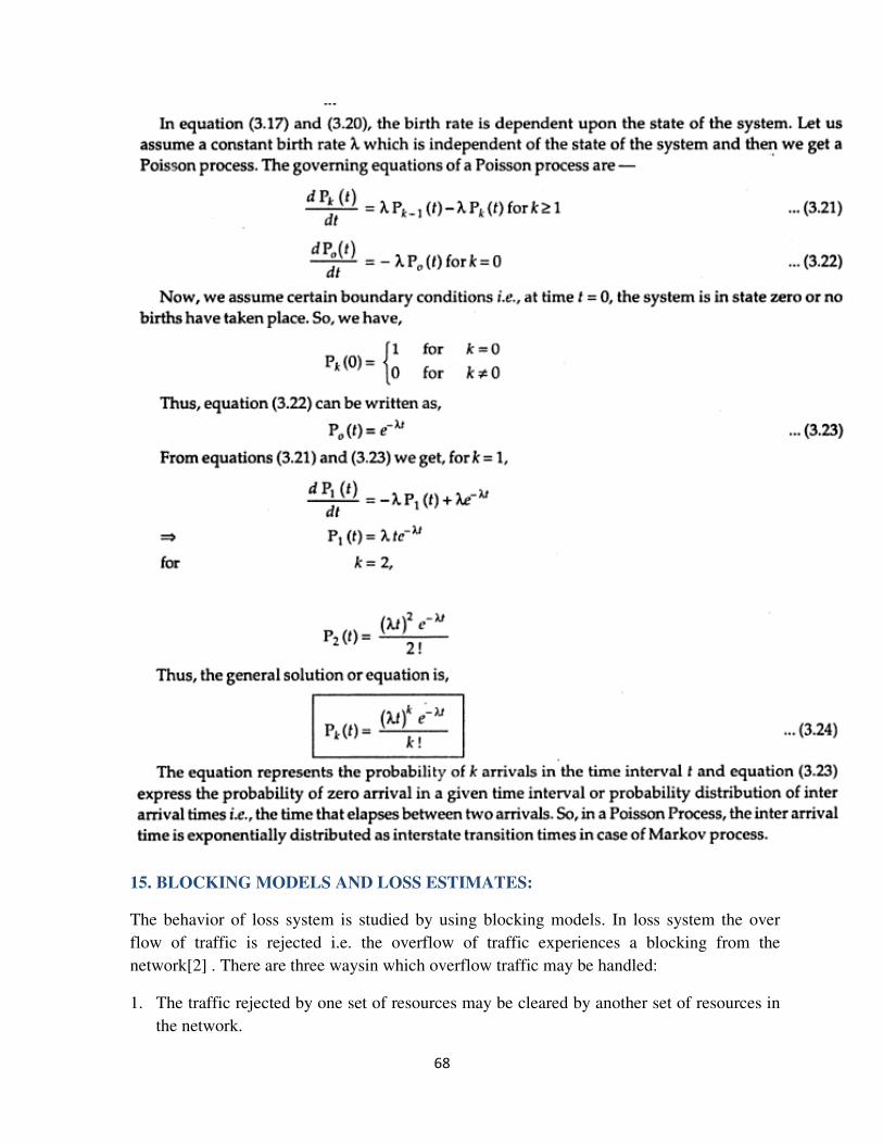
68
15. BLOCKING MODELS AND LOSS ESTIMATES:
The behavior of loss system is studied by using blocking models. In loss system the over
flow of traffic is rejected i.e. the overflow of traffic experiences a blocking from the
network[2] . There are three waysin which overflow traffic may be handled:
1. The traffic rejected by one set of resources may be cleared by another set of resources in
the network.
69
2. The traffic may return to the same resource after some time.
3. The traffic may be held by the resource as if being serviced but actually serviced only
after the resources become available.
Corresponding to the above three cases, we consider three models of loss systems:
a. Lost calls cleared (LCC)
b. Lost calls returned (LCR)
c. Lost calls held (LCH)
a. Lost calls cleared (LCC):
a.1. Lost calls cleared system with infinite sources :
Let’s assume the LCC system using infinite number of subscribers. This model is well
suited for study of the behavior of the trunk transmission systems. Usually there are many trunk
groups emanating from a switching office and terminating on adjacent switching offices.
Whenever a direct trunk group between two switching offices is busy, it is possible to divert the
traffic via other switching offices using different trunk groups. In this way the blocked calls in
one trunk group are cleared via other trunk group
The LCC model assumes that the subscriber on hearing the engaged tone, hangs up and waits for
some length of time before reattempting. He does not reattempt immediately or within a short
time. Such calls are considered to have been cleared from the system and the reattempts are
treated as new calls.
The LCC model was first studied by A. K. Erlang in 1917.The main purpose of the analysis is to
estimate the blocking probability and the grade of service.Consider the Erlang loss system with
N fully accessible lines and exponential holding times. The Erlang loss system can be modeled
by birth and death process with birth and death rate as follows.
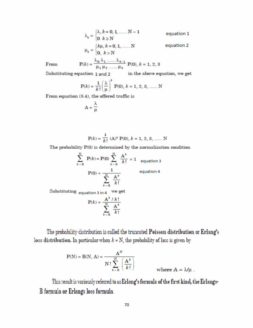
70
71
A.2 Lost Calls Cleared system with finite subscribers:
In case of LCC model with finite subscribers, the call arrival rate is dependent on the number of
subscribers, who are not occupied as the busy subscribers do not generate new calls. The traffic
in this case is known as Engest traffic or pure chance traffic type 2.
72
B. Lost Calls Returned System:
LCR model based on the assumption that the blocked calls return to the system as a form of
retries.So that the offered traffic comprisestwo components:
Offered traffic = new traffic + retry traffic
The following assumptions are made to analyse the LCR model with regard to the nature of
returning calls [1] .
I. Retries calls get the service even if multiple retries are required.
73
II. No new call is generated when a blocked call is being retried.
III. Time between call blocking and regeneration is random stastistically independent of each
other.
IV. Typical working time before a retry is longer than the average holding time .
V. If retries are immidiate ,congestion may occur or the network operation becomes delay
system.
Suppose a system with first attempt call arrival ratio of λ=100 (say).If a percentage B of the call
is blocked,B times λ retries.
C. Lost Calls Held System:
I. In this case, the blocked calls are held in a queue and serviced when necessary facilities
become available.
II. In this system, the total time is not dependent on the waiting time. The total time is
determined by the average service time required.
III. The sources need service continuously for a period of time whether or not the services are
available. As the service becomes free from other calls it handles the queued calls.
IV. If a number of calls blocked, a portion of it is lost until a server become free to service a
call as shown in figure
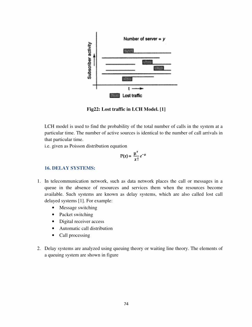
74
Fig22: Lost traffic in LCH Model. [1]
LCH model is used to find the probability of the total number of calls in the system at a
particular time. The number of active sources is identical to the number of call arrivals in
that particular time.
i.e. given as Poisson distribution equation
16. DELAY SYSTEMS:
1. In telecommunication network, such as data network places the call or messages in a
queue in the absence of resources and services them when the resources become
available. Such systems are known as delay systems, which are also called lost call
delayed systems [1]. For example:
• Message switching
• Packet switching
• Digital receiver access
• Automatic call distribution
• Call processing
2. Delay systems are analyzed using queuing theory or waiting line theory. The elements of
a queuing system are shown in figure
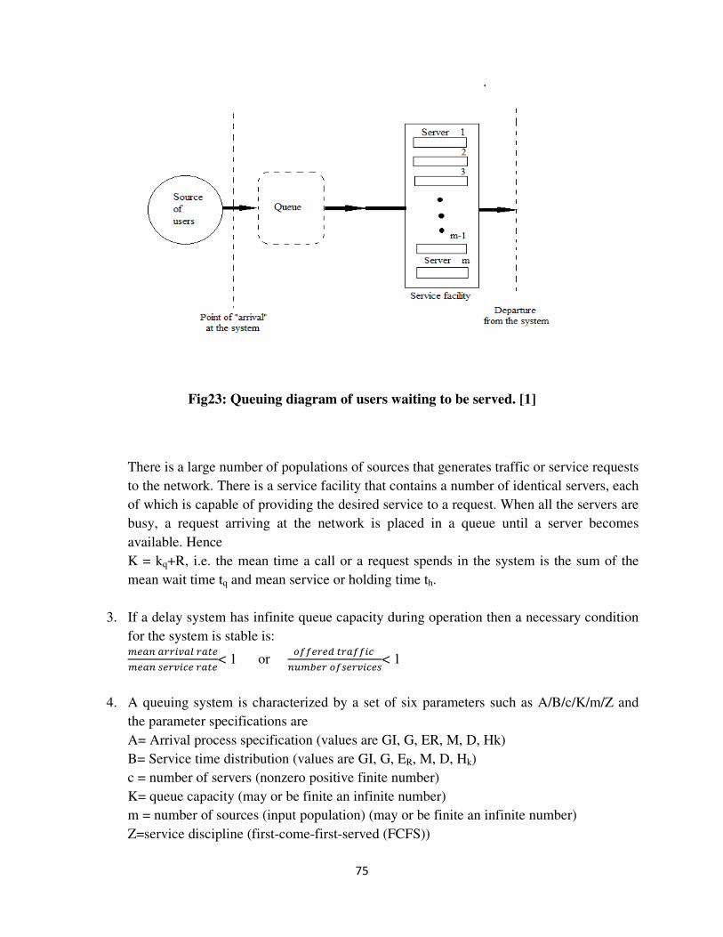
75
Fig23: Queuing diagram of users waiting to be served. [1]
There is a large number of populations of sources that generates traffic or service requests
to the network. There is a service facility that contains a number of identical servers, each
of which is capable of providing the desired service to a request. When all the servers are
busy, a request arriving at the network is placed in a queue until a server becomes
available. Hence
K = kq+R, i.e. the mean time a call or a request spends in the system is the sum of the
mean wait time tq and mean service or holding time th.
3. If a delay system has infinite queue capacity during operation then a necessary condition
for the system is stable is: %&'(' )*'+ '�&%&'(�& *),& '�&< 1 or
-..& &�� '..),(/%0& -.�& *),&�< 1
4. A queuing system is characterized by a set of six parameters such as A/B/c/K/m/Z and
the parameter specifications are
A= Arrival process specification (values are GI, G, ER, M, D, Hk)
B= Service time distribution (values are GI, G, ER, M, D, Hk)
c = number of servers (nonzero positive finite number)
K= queue capacity (may or be finite an infinite number)
m = number of sources (input population) (may or be finite an infinite number)
Z=service discipline (first-come-first-served (FCFS))
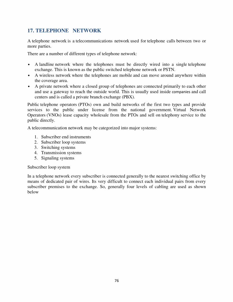
76
17. TELEPHONE NETWORK
A telephone network is a telecommunications network used for telephone calls between two or
more parties.
There are a number of different types of telephone network:
• A landline network where the telephones must be directly wired into a single telephone
exchange. This is known as the public switched telephone network or PSTN.
• A wireless network where the telephones are mobile and can move around anywhere within
the coverage area.
• A private network where a closed group of telephones are connected primarily to each other
and use a gateway to reach the outside world. This is usually used inside companies and call
centers and is called a private branch exchange (PBX).
Public telephone operators (PTOs) own and build networks of the first two types and provide
services to the public under license from the national government. Virtual Network
Operators (VNOs) lease capacity wholesale from the PTOs and sell on telephony service to the
public directly.
A telecommunication network may be categorized into major systems:
1. Subscriber end instruments
2. Subscriber loop systems
3. Switching systems
4. Transmission systems
5. Signaling systems
Subscriber loop system
In a telephone network every subscriber is connected generally to the nearest switching office by
means of dedicated pair of wires. Its very difficult to connect each individual pairs from every
subscriber premises to the exchange. So, generally four levels of cabling are used as shown
below
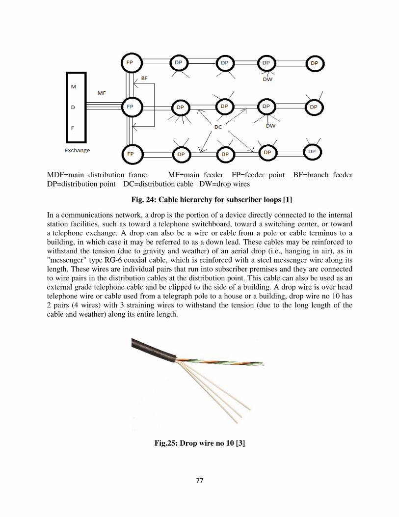
77
MDF=main distribution frame MF=main feeder FP=feeder point BF=branch feeder
DP=distribution point DC=distribution cable DW=drop wires
Fig. 24: Cable hierarchy for subscriber loops [1]
In a communications network, a drop is the portion of a device directly connected to the internal
station facilities, such as toward a telephone switchboard, toward a switching center, or toward
a telephone exchange. A drop can also be a wire or cable from a pole or cable terminus to a
building, in which case it may be referred to as a down lead. These cables may be reinforced to
withstand the tension (due to gravity and weather) of an aerial drop (i.e., hanging in air), as in
"messenger" type RG-6 coaxial cable, which is reinforced with a steel messenger wire along its
length. These wires are individual pairs that run into subscriber premises and they are connected
to wire pairs in the distribution cables at the distribution point. This cable can also be used as an
external grade telephone cable and be clipped to the side of a building. A drop wire is over head
telephone wire or cable used from a telegraph pole to a house or a building, drop wire no 10 has
2 pairs (4 wires) with 3 straining wires to withstand the tension (due to the long length of the
cable and weather) along its entire length.
Fig.25: Drop wire no 10 [3]
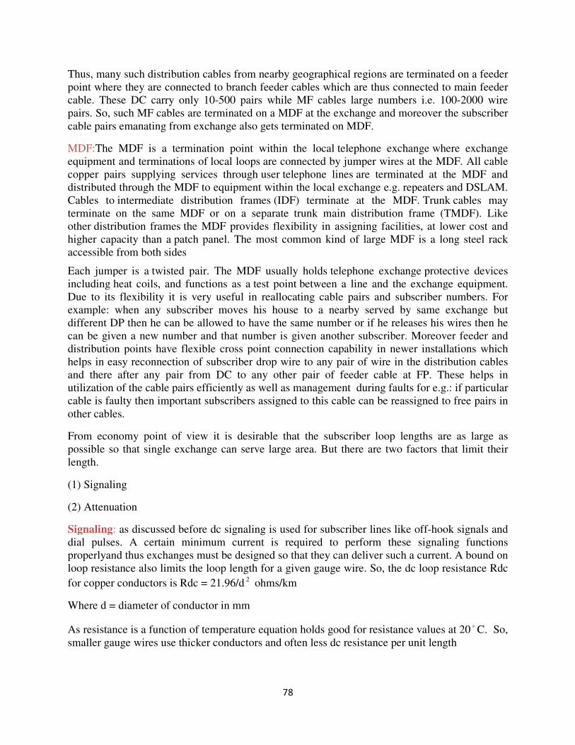
78
Thus, many such distribution cables from nearby geographical regions are terminated on a feeder
point where they are connected to branch feeder cables which are thus connected to main feeder
cable. These DC carry only 10-500 pairs while MF cables large numbers i.e. 100-2000 wire
pairs. So, such MF cables are terminated on a MDF at the exchange and moreover the subscriber
cable pairs emanating from exchange also gets terminated on MDF.
MDF:The MDF is a termination point within the local telephone exchange where exchange
equipment and terminations of local loops are connected by jumper wires at the MDF. All cable
copper pairs supplying services through user telephone lines are terminated at the MDF and
distributed through the MDF to equipment within the local exchange e.g. repeaters and DSLAM.
Cables to intermediate distribution frames (IDF) terminate at the MDF. Trunk cables may
terminate on the same MDF or on a separate trunk main distribution frame (TMDF). Like
other distribution frames the MDF provides flexibility in assigning facilities, at lower cost and
higher capacity than a patch panel. The most common kind of large MDF is a long steel rack
accessible from both sides
Each jumper is a twisted pair. The MDF usually holds telephone exchange protective devices
including heat coils, and functions as a test point between a line and the exchange equipment.
Due to its flexibility it is very useful in reallocating cable pairs and subscriber numbers. For
example: when any subscriber moves his house to a nearby served by same exchange but
different DP then he can be allowed to have the same number or if he releases his wires then he
can be given a new number and that number is given another subscriber. Moreover feeder and
distribution points have flexible cross point connection capability in newer installations which
helps in easy reconnection of subscriber drop wire to any pair of wire in the distribution cables
and there after any pair from DC to any other pair of feeder cable at FP. These helps in
utilization of the cable pairs efficiently as well as management during faults for e.g.: if particular
cable is faulty then important subscribers assigned to this cable can be reassigned to free pairs in
other cables.
From economy point of view it is desirable that the subscriber loop lengths are as large as
possible so that single exchange can serve large area. But there are two factors that limit their
length.
(1) Signaling
(2) Attenuation
Signaling: as discussed before dc signaling is used for subscriber lines like off-hook signals and
dial pulses. A certain minimum current is required to perform these signaling functions
properlyand thus exchanges must be designed so that they can deliver such a current. A bound on
loop resistance also limits the loop length for a given gauge wire. So, the dc loop resistance Rdc
for copper conductors is Rdc = 21.96/d 2 ohms/km
Where d = diameter of conductor in mm
As resistance is a function of temperature equation holds good for resistance values at 20 o C. So,
smaller gauge wires use thicker conductors and often less dc resistance per unit length
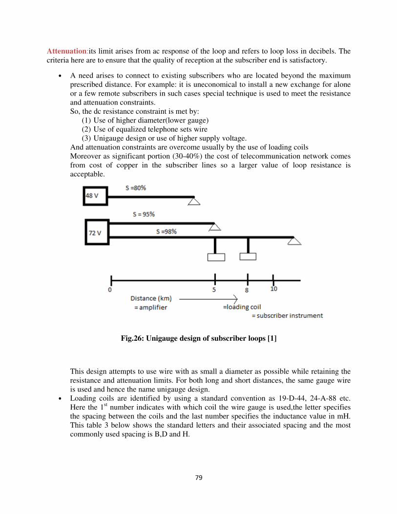
79
Attenuation:its limit arises from ac response of the loop and refers to loop loss in decibels. The
criteria here are to ensure that the quality of reception at the subscriber end is satisfactory.
• A need arises to connect to existing subscribers who are located beyond the maximum
prescribed distance. For example: it is uneconomical to install a new exchange for alone
or a few remote subscribers in such cases special technique is used to meet the resistance
and attenuation constraints.
So, the dc resistance constraint is met by:
(1) Use of higher diameter(lower gauge)
(2) Use of equalized telephone sets wire
(3) Unigauge design or use of higher supply voltage.
And attenuation constraints are overcome usually by the use of loading coils
Moreover as significant portion (30-40%) the cost of telecommunication network comes
from cost of copper in the subscriber lines so a larger value of loop resistance is
acceptable.
Fig.26: Unigauge design of subscriber loops [1]
This design attempts to use wire with as small a diameter as possible while retaining the
resistance and attenuation limits. For both long and short distances, the same gauge wire
is used and hence the name unigauge design.
• Loading coils are identified by using a standard convention as 19-D-44, 24-A-88 etc.
Here the 1st number indicates with which coil the wire gauge is used,the letter specifies
the spacing between the coils and the last number specifies the inductance value in mH.
This table 3 below shows the standard letters and their associated spacing and the most
commonly used spacing is B,D and H.
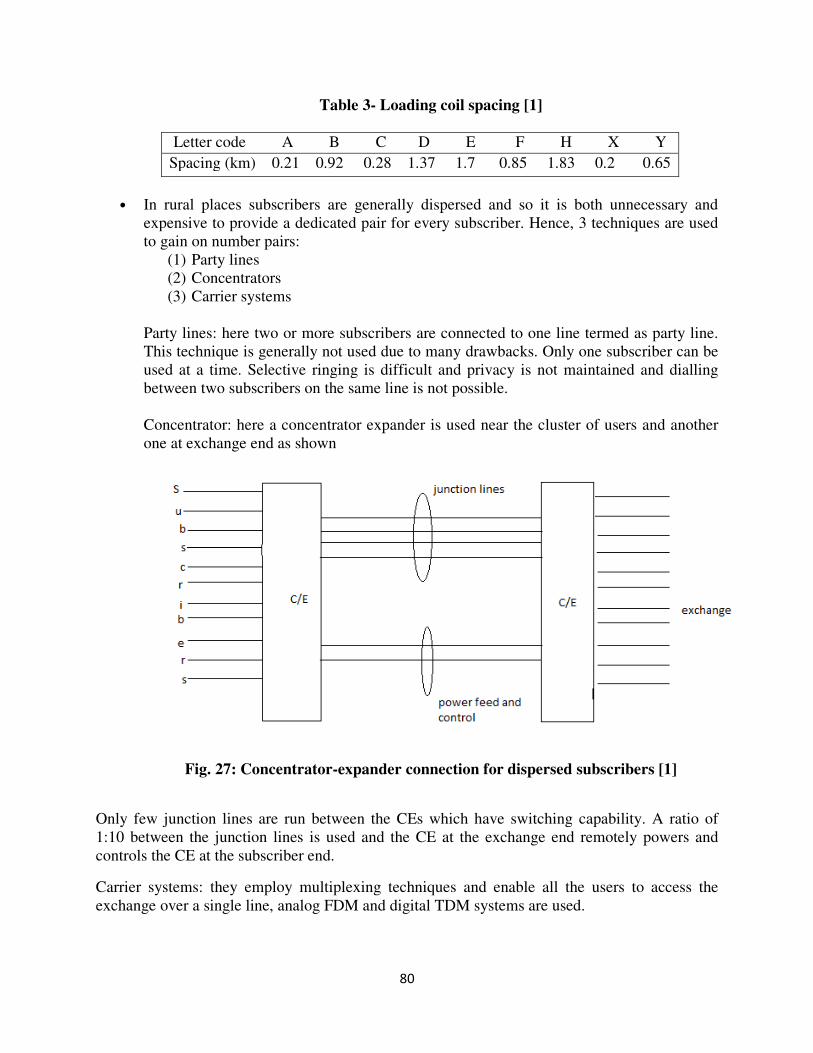
80
Table 3- Loading coil spacing [1]
Letter code A B C D E F H X Y
Spacing (km) 0.21 0.92 0.28 1.37 1.7 0.85 1.83 0.2 0.65
• In rural places subscribers are generally dispersed and so it is both unnecessary and
expensive to provide a dedicated pair for every subscriber. Hence, 3 techniques are used
to gain on number pairs:
(1) Party lines
(2) Concentrators
(3) Carrier systems
Party lines: here two or more subscribers are connected to one line termed as party line.
This technique is generally not used due to many drawbacks. Only one subscriber can be
used at a time. Selective ringing is difficult and privacy is not maintained and dialling
between two subscribers on the same line is not possible.
Concentrator: here a concentrator expander is used near the cluster of users and another
one at exchange end as shown
Fig. 27: Concentrator-expander connection for dispersed subscribers [1]
Only few junction lines are run between the CEs which have switching capability. A ratio of
1:10 between the junction lines is used and the CE at the exchange end remotely powers and
controls the CE at the subscriber end.
Carrier systems: they employ multiplexing techniques and enable all the users to access the
exchange over a single line, analog FDM and digital TDM systems are used.
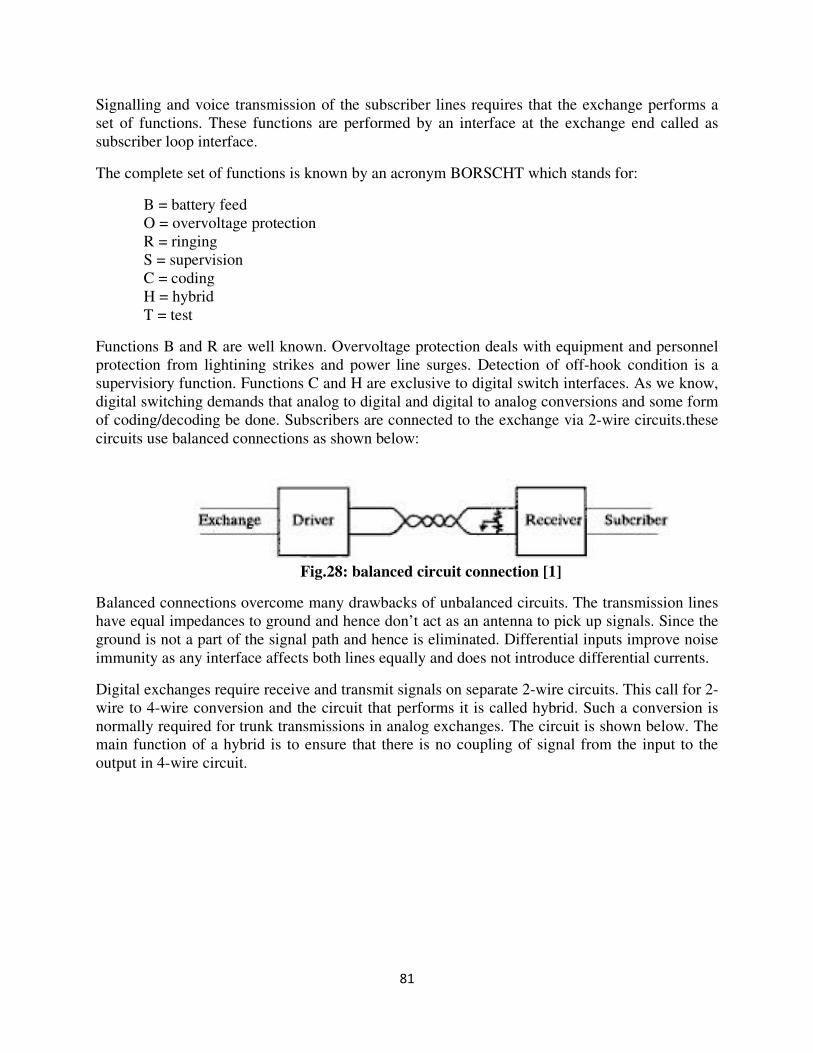
81
Signalling and voice transmission of the subscriber lines requires that the exchange performs a
set of functions. These functions are performed by an interface at the exchange end called as
subscriber loop interface.
The complete set of functions is known by an acronym BORSCHT which stands for:
B = battery feed
O = overvoltage protection
R = ringing
S = supervision
C = coding
H = hybrid
T = test
Functions B and R are well known. Overvoltage protection deals with equipment and personnel
protection from lightining strikes and power line surges. Detection of off-hook condition is a
supervisiory function. Functions C and H are exclusive to digital switch interfaces. As we know,
digital switching demands that analog to digital and digital to analog conversions and some form
of coding/decoding be done. Subscribers are connected to the exchange via 2-wire circuits.these
circuits use balanced connections as shown below:
Fig.28: balanced circuit connection [1]
Balanced connections overcome many drawbacks of unbalanced circuits. The transmission lines
have equal impedances to ground and hence don’t act as an antenna to pick up signals. Since the
ground is not a part of the signal path and hence is eliminated. Differential inputs improve noise
immunity as any interface affects both lines equally and does not introduce differential currents.
Digital exchanges require receive and transmit signals on separate 2-wire circuits. This call for 2-
wire to 4-wire conversion and the circuit that performs it is called hybrid. Such a conversion is
normally required for trunk transmissions in analog exchanges. The circuit is shown below. The
main function of a hybrid is to ensure that there is no coupling of signal from the input to the
output in 4-wire circuit.
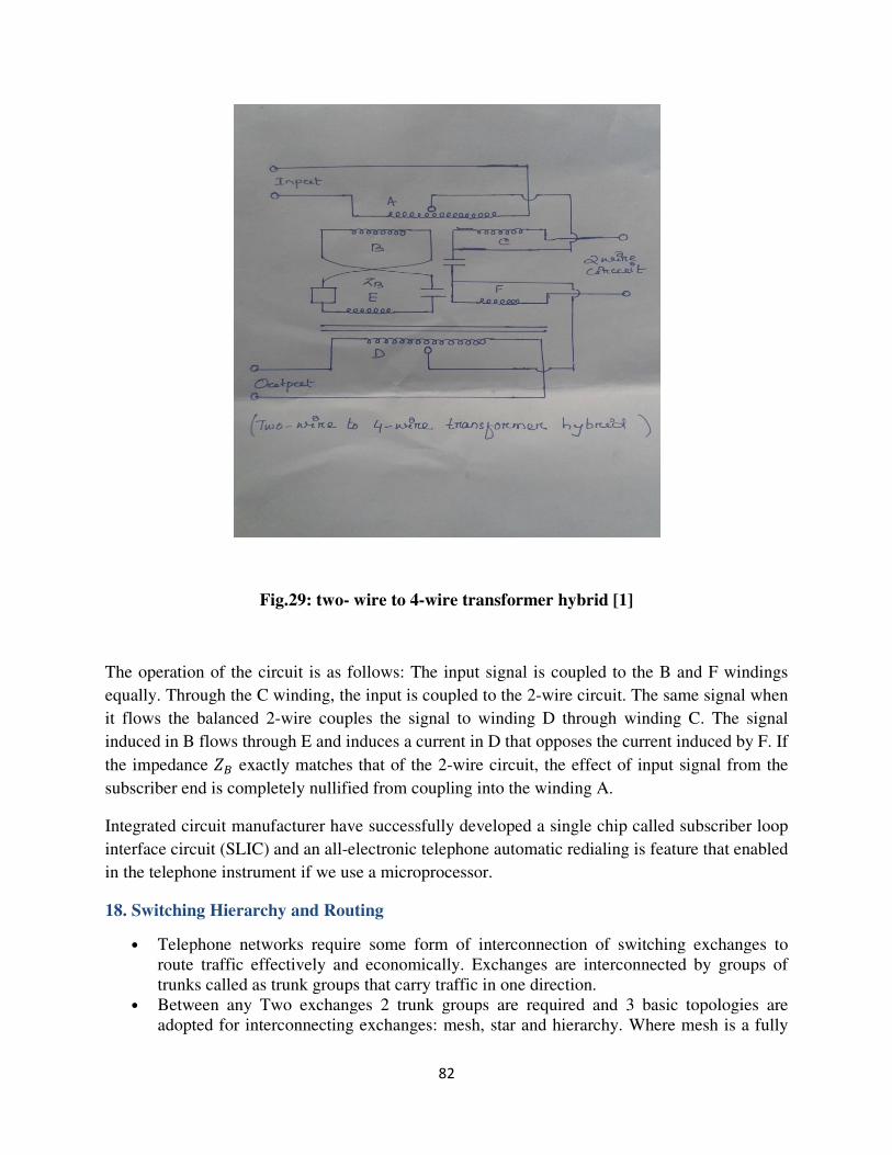
82
Fig.29: two- wire to 4-wire transformer hybrid [1]
The operation of the circuit is as follows: The input signal is coupled to the B and F windings
equally. Through the C winding, the input is coupled to the 2-wire circuit. The same signal when
it flows the balanced 2-wire couples the signal to winding D through winding C. The signal
induced in B flows through E and induces a current in D that opposes the current induced by F. If
the impedance 1� exactly matches that of the 2-wire circuit, the effect of input signal from the
subscriber end is completely nullified from coupling into the winding A.
Integrated circuit manufacturer have successfully developed a single chip called subscriber loop
interface circuit (SLIC) and an all-electronic telephone automatic redialing is feature that enabled
in the telephone instrument if we use a microprocessor.
18. Switching Hierarchy and Routing
• Telephone networks require some form of interconnection of switching exchanges to
route traffic effectively and economically. Exchanges are interconnected by groups of
trunks called as trunk groups that carry traffic in one direction.
• Between any Two exchanges 2 trunk groups are required and 3 basic topologies are
adopted for interconnecting exchanges: mesh, star and hierarchy. Where mesh is a fully
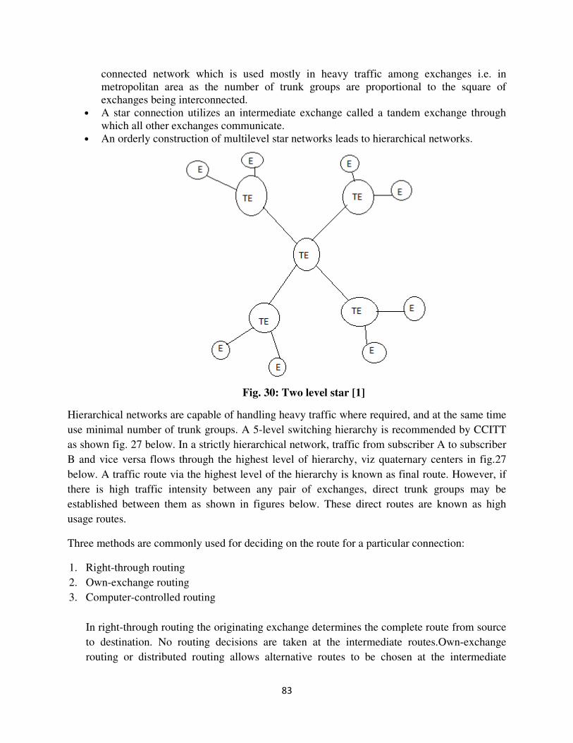
83
connected network which is used mostly in heavy traffic among exchanges i.e. in
metropolitan area as the number of trunk groups are proportional to the square of
exchanges being interconnected.
• A star connection utilizes an intermediate exchange called a tandem exchange through
which all other exchanges communicate.
• An orderly construction of multilevel star networks leads to hierarchical networks.
Fig. 30: Two level star [1]
Hierarchical networks are capable of handling heavy traffic where required, and at the same time
use minimal number of trunk groups. A 5-level switching hierarchy is recommended by CCITT
as shown fig. 27 below. In a strictly hierarchical network, traffic from subscriber A to subscriber
B and vice versa flows through the highest level of hierarchy, viz quaternary centers in fig.27
below. A traffic route via the highest level of the hierarchy is known as final route. However, if
there is high traffic intensity between any pair of exchanges, direct trunk groups may be
established between them as shown in figures below. These direct routes are known as high
usage routes.
Three methods are commonly used for deciding on the route for a particular connection:
1. Right-through routing
2. Own-exchange routing
3. Computer-controlled routing
In right-through routing the originating exchange determines the complete route from source
to destination. No routing decisions are taken at the intermediate routes.Own-exchange
routing or distributed routing allows alternative routes to be chosen at the intermediate
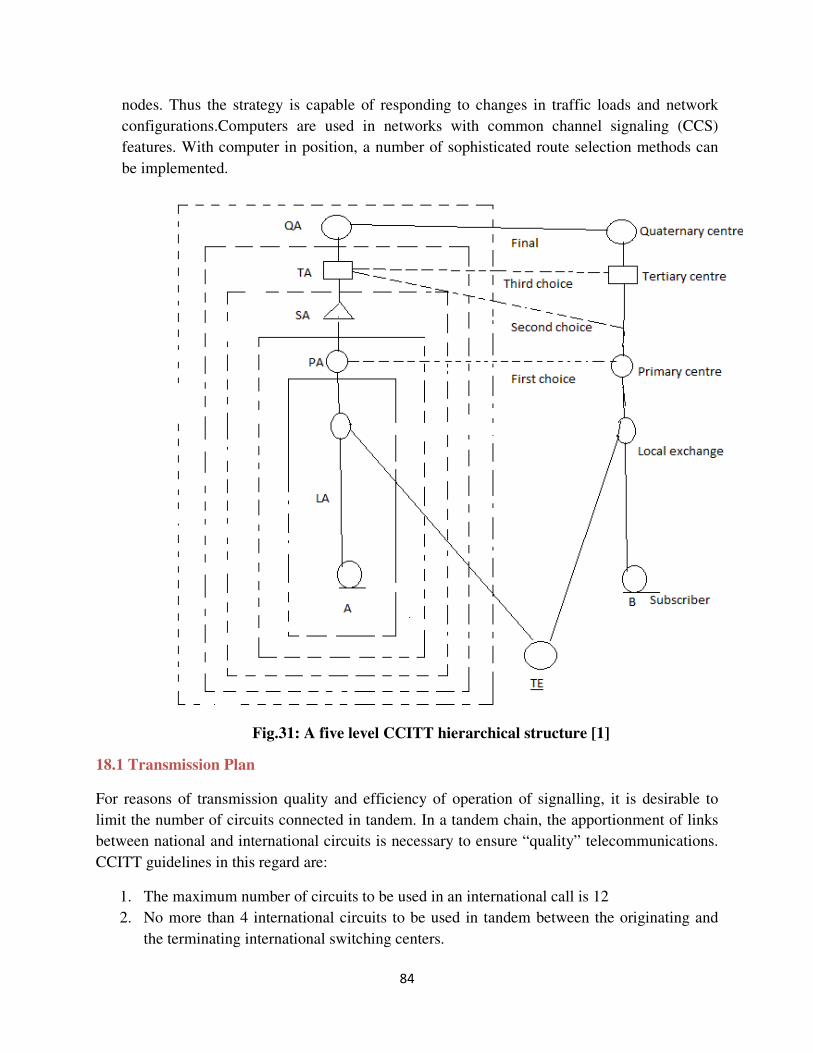
84
nodes. Thus the strategy is capable of responding to changes in traffic loads and network
configurations.Computers are used in networks with common channel signaling (CCS)
features. With computer in position, a number of sophisticated route selection methods can
be implemented.
Fig.31: A five level CCITT hierarchical structure [1]
18.1 Transmission Plan
For reasons of transmission quality and efficiency of operation of signalling, it is desirable to
limit the number of circuits connected in tandem. In a tandem chain, the apportionment of links
between national and international circuits is necessary to ensure “quality” telecommunications.
CCITT guidelines in this regard are:
1. The maximum number of circuits to be used in an international call is 12
2. No more than 4 international circuits to be used in tandem between the originating and
the terminating international switching centers.
85
3. In exceptional cases and for low number of calls the total number of circuits may be 14,
but even in this case, the international circuits are limited to a maximum of 4.
Taking guidelines 1 & 2 we have 8 links available for national circuits, which implies a limit of
four for each national circuits.
The transmission loss is defined in terms of reference equivalents of TRE, ORE and RRE.
CCITT recommends that for 97% of the connections the maximum TRE is limited to 20.8dB and
RRE to 12.2dB between the subscriber and the international interface in the national network.
This gives an overall reference equivalent ORE of 33 db. From one country to another the OREs
range is from 6 to 26 db.
Transmission losses budget should provide for 2 factors other than line and switch losses:
1. Keeping echo levels within limits
2. Control singing.
In analog exchanges, local calls are established on 2 wire circuits. But long distance calls require
2 wire to 4 wire conversion at the subscriber line trunk interface. Due to long distance involved,
the bearer circuits need amplifiers or repeaters at appropriate intervals to boost the signals. The
amplifiers are almost invariably one way devices. Since for long distance circuits need separate
for each direction, leading to conversion into a 4 wire circuits.
The important function of the hybrid is to ensure that the received signal is not coupled. The
coupling is zero only when the 2 wire circuit and the 4 wire circuit impedances are perfectly
matched. However impedance mismatch occurs in most of the connections at the subscriber line
trunk interface. The effect of such mismatch results in echo. If the distance are short , the round
trip delay experienced by the echo is small and becomes unnoticeable.
The echo suppressors are voice attenuators. Normally the echo suppressors remain in a
deactivated state. Speech in one channel activates the echo suppressor in the return path. One
drawback of echo suppressors is that they may clip the beginning portion of speech segments.
New designsof echo suppressors attempt to minimize the time required to reverse directions.
Typical reversal times are in the range of 2-5 ms.
The operation of a system with echo suppressors is clearly half duplex. When telephone lines are
used for data transmission full duplex operation is required. Echo suppressors are usually turned
off for data transmission as it is very difficult to organize data transmission. This is done by
providing a disabler feature in the echo suppressor and triggering the same with a special signal.
Usually a 2025 Hz or 2100 Hz tone transmitted for at least duration of 300 ms with a signal not
less than -5 dB is used to trigger the disabler.Once the time increases the echo becomes
noticeable and annoying to the speaker.
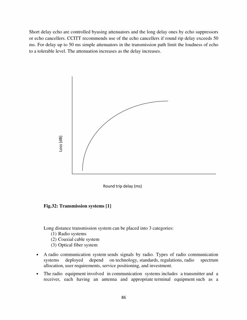
86
Short delay echo are controlled byusing attenuators and the long delay ones by echo suppressors
or echo cancellers. CCITT recommends use of the echo cancellers if round rip delay exceeds 50
ms. For delay up to 50 ms simple attenuators in the transmission path limit the loudness of echo
to a tolerable level. The attenuation increases as the delay increases.
Fig.32: Transmission systems [1]
Long distance transmission system can be placed into 3 categories:
(1) Radio systems
(2) Coaxial cable system
(3) Optical fiber system
• A radio communication system sends signals by radio. Types of radio communication
systems deployed depend on technology, standards, regulations, radio spectrum
allocation, user requirements, service positioning, and investment.
• The radio equipment involved in communication systems includes a transmitter and a
receiver, each having an antenna and appropriate terminal equipment such as a
Round trip delay (ms)
Loss
(d
B)
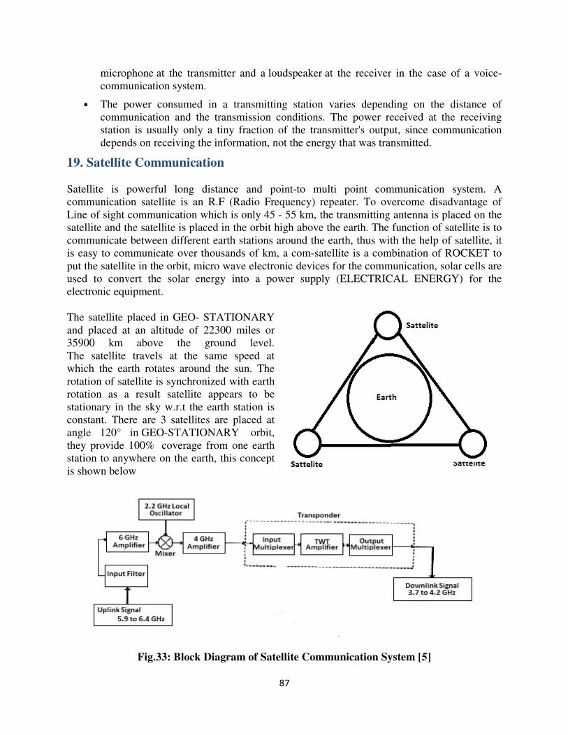
87
microphone at the transmitter and a loudspeaker at the receiver in the case of a voice-
communication system.
• The power consumed in a transmitting station varies depending on the distance of
communication and the transmission conditions. The power received at the receiving
station is usually only a tiny fraction of the transmitter's output, since communication
depends on receiving the information, not the energy that was transmitted.
19. Satellite Communication
Satellite is powerful long distance and point-to multi point communication system. A
communication satellite is an R.F (Radio Frequency) repeater. To overcome disadvantage of
Line of sight communication which is only 45 - 55 km, the transmitting antenna is placed on the
satellite and the satellite is placed in the orbit high above the earth. The function of satellite is to
communicate between different earth stations around the earth, thus with the help of satellite, it
is easy to communicate over thousands of km, a com-satellite is a combination of ROCKET to
put the satellite in the orbit, micro wave electronic devices for the communication, solar cells are
used to convert the solar energy into a power supply (ELECTRICAL ENERGY) for the
electronic equipment.
The satellite placed in GEO- STATIONARY
and placed at an altitude of 22300 miles or
35900 km above the ground level.
The satellite travels at the same speed at
which the earth rotates around the sun. The
rotation of satellite is synchronized with earth
rotation as a result satellite appears to be
stationary in the sky w.r.t the earth station is
constant. There are 3 satellites are placed at
angle 120° in GEO-STATIONARY orbit,
they provide 100% coverage from one earth
station to anywhere on the earth, this concept
is shown below
Fig.33: Block Diagram of Satellite Communication System [5]
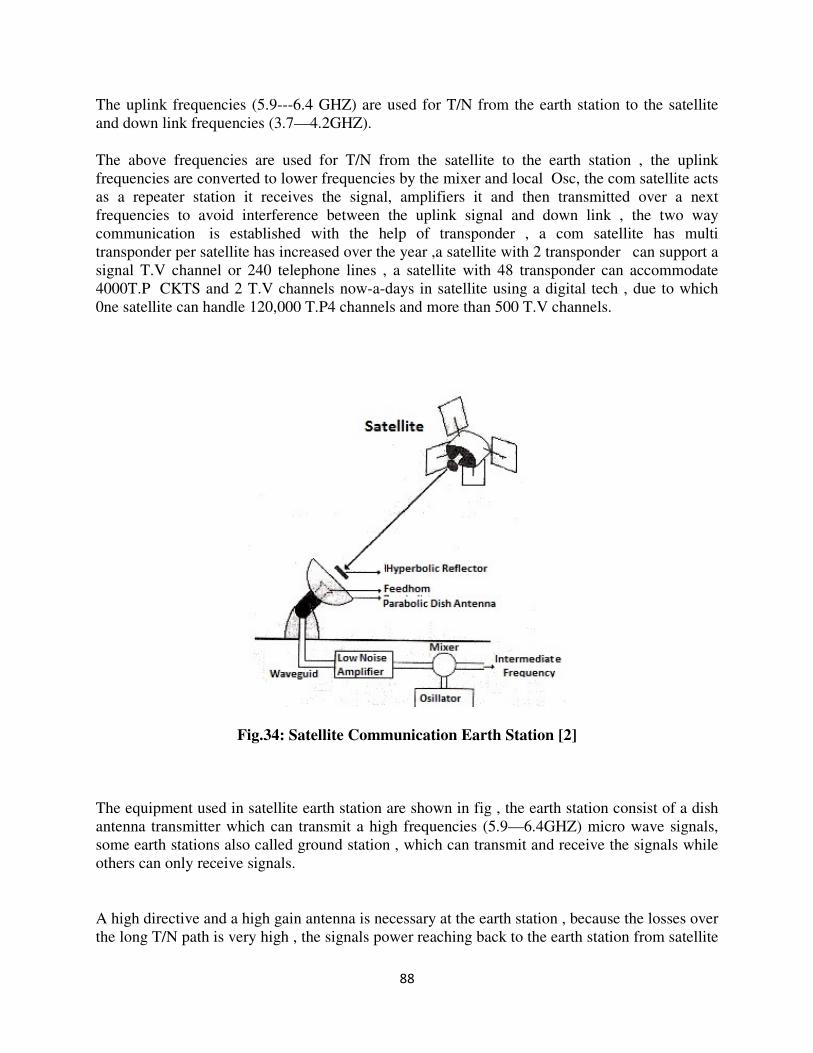
88
The uplink frequencies (5.9---6.4 GHZ) are used for T/N from the earth station to the satellite
and down link frequencies (3.7—4.2GHZ).
The above frequencies are used for T/N from the satellite to the earth station , the uplink
frequencies are converted to lower frequencies by the mixer and local Osc, the com satellite acts
as a repeater station it receives the signal, amplifiers it and then transmitted over a next
frequencies to avoid interference between the uplink signal and down link , the two way
communication is established with the help of transponder , a com satellite has multi
transponder per satellite has increased over the year ,a satellite with 2 transponder can support a
signal T.V channel or 240 telephone lines , a satellite with 48 transponder can accommodate
4000T.P CKTS and 2 T.V channels now-a-days in satellite using a digital tech , due to which
0ne satellite can handle 120,000 T.P4 channels and more than 500 T.V channels.
Fig.34: Satellite Communication Earth Station [2]
The equipment used in satellite earth station are shown in fig , the earth station consist of a dish
antenna transmitter which can transmit a high frequencies (5.9—6.4GHZ) micro wave signals,
some earth stations also called ground station , which can transmit and receive the signals while
others can only receive signals.
A high directive and a high gain antenna is necessary at the earth station , because the losses over
the long T/N path is very high , the signals power reaching back to the earth station from satellite
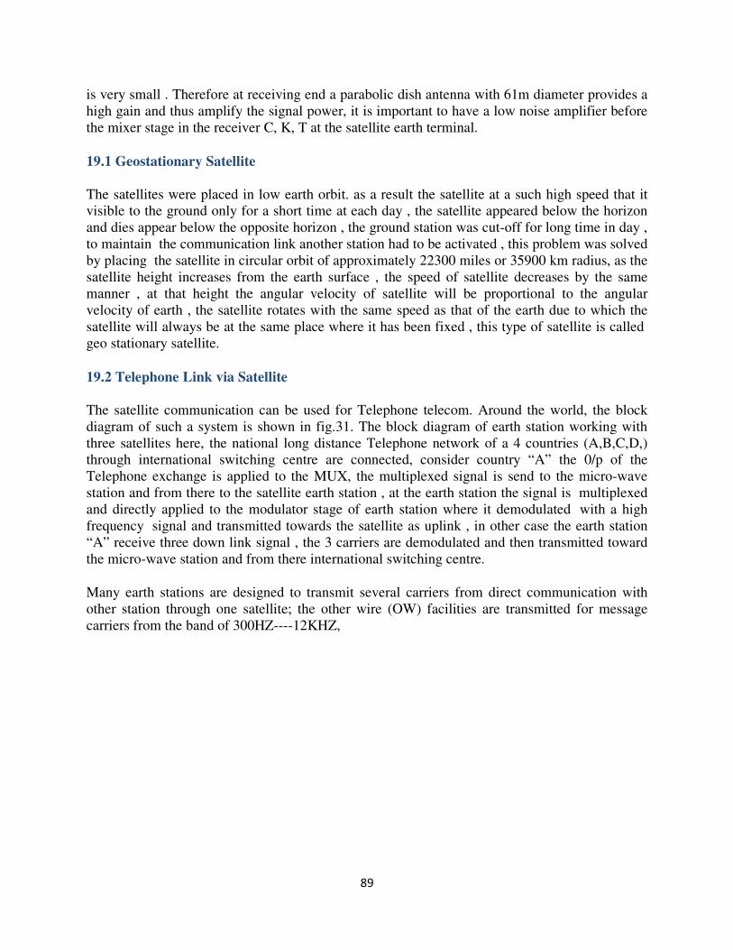
89
is very small . Therefore at receiving end a parabolic dish antenna with 61m diameter provides a
high gain and thus amplify the signal power, it is important to have a low noise amplifier before
the mixer stage in the receiver C, K, T at the satellite earth terminal.
19.1 Geostationary Satellite
The satellites were placed in low earth orbit. as a result the satellite at a such high speed that it
visible to the ground only for a short time at each day , the satellite appeared below the horizon
and dies appear below the opposite horizon , the ground station was cut-off for long time in day ,
to maintain the communication link another station had to be activated , this problem was solved
by placing the satellite in circular orbit of approximately 22300 miles or 35900 km radius, as the
satellite height increases from the earth surface , the speed of satellite decreases by the same
manner , at that height the angular velocity of satellite will be proportional to the angular
velocity of earth , the satellite rotates with the same speed as that of the earth due to which the
satellite will always be at the same place where it has been fixed , this type of satellite is called
geo stationary satellite.
19.2 Telephone Link via Satellite
The satellite communication can be used for Telephone telecom. Around the world, the block
diagram of such a system is shown in fig.31. The block diagram of earth station working with
three satellites here, the national long distance Telephone network of a 4 countries (A,B,C,D,)
through international switching centre are connected, consider country “A” the 0/p of the
Telephone exchange is applied to the MUX, the multiplexed signal is send to the micro-wave
station and from there to the satellite earth station , at the earth station the signal is multiplexed
and directly applied to the modulator stage of earth station where it demodulated with a high
frequency signal and transmitted towards the satellite as uplink , in other case the earth station
“A” receive three down link signal , the 3 carriers are demodulated and then transmitted toward
the micro-wave station and from there international switching centre.
Many earth stations are designed to transmit several carriers from direct communication with
other station through one satellite; the other wire (OW) facilities are transmitted for message
carriers from the band of 300HZ----12KHZ,
90
Fig.35: Satellite communication used for telecom [2]
Merits
1. No tracking is required by Geostationary Satellites.
2. Multiple access points are available in Satellite communication.
3. 24 hour communication can be achieved with the help of satellite.
4. The signal quality of Satellite communication is higher.
5. To put more information on the carrier a broad band can be used.
6. Satellite Communication is used for long distance communication or across oceans.
7. Low transmitting Power and low receiver sensitivity is required by the Satellite in close
elliptical orbits.
Demerits
1. The transmitter and receiver used in satellite communication require high power, most
sensitive transmitters and large diameter antennas.
2. Satellite communication is disturbed by solar activities and cyclones in the space.
3. Due to ageing effect the efficiency of Satellite components decreases.
4. The longer propagation times (APPOX, 300ms) is one of a disadvantage of satellite
communication.
5. The cost for Initial design and launching of the satellite in the orbit results in extremely
high.
91
20. Numbering plans The objective of numbering plan is to uniquely identify every subscriber connected to a
telecommunication network. In early stages of development a numbering scheme was confined
to a single local exchange, and exchanges were identified by the names of the towns in which
they were located. This scheme works well as long as there is only one exchange per town. But
as the subscriber volume grew, it became necessary to introduce more than one exchange in a
town. Generally, a largecentrally located exchange called the main exchange serving the main
business center of the town, and a number of smaller exchanges known as satellite exchanges
serving different residential localities were used to cope with the growing traffic in a large area.
The area containing the complete network of the main exchange, and the satellite is known as
multiexchange area. A common numbering scheme was then required for the area so that the
digits dialed to identify a given terminating exchange do not vary with the exchange originating
the call. For call originating from a location outside the multi-exchange area, there is a need to
identify the area by a common code. The common numbering scheme is sometimes called as the
linked numbering scheme. In this scheme, all exchanges in a townwere collectively identified
by the name of the town.The introduction of subscriber trunkdialing(STD) or directdistance
dialing(DDD) for intercity and intertown long distance connection called for a national
numbering plan, where multiexchange areas are identified uniquely by numbers. Subsequent
development of internationalsubscriber dialing (ISD) makes it necessary to have an
international numbering plans and to have the national numbering plan conform to the
international one. A numbering plan may be open, semi open, or closed. An open numbering
plan, also known as non-uniform numbering scheme, permit wide variation in the number of
digits to be used to identify a subscriber within a multiexchange area or within a country. This
plan is used in countries equipped extensively with non-Director Strowger switching systems. In
such cases, the numbering scheme is usually an exact image of the network structure and
requires to be changed if the networkstructure changes.
A semiopen plan permits number lengths to differ by at most one or two digits. Today the
scheme is the most common and is used in many countries including India, Sweden, Switzerland,
and the United Kingdom. In closed numbering plan the uniform numbering scheme, the
number of digits in a subscriber number is fixed. This scheme is used by a few countries which
include from France, Belgium and the countries in the North America(USA,Canada). An
international numbering plan or world numbering plan has been refined by CCITT in its
recommendation. For the number of purposes, the world is divided into zones. Each zone is
given a single digit code. For the European zone, two codes have been allotted because of the
large number of countries within this zone. Every international telephone number consists of two
parts.
The country code contains one, two or three digits, the first digit being the zone code in which
the country lies. For example France has the country code '33'. In cases where an integrated
numbering plan already covers an entire zone, the countries in that zone are identified by the
single digit zone code itself. All the countries in the North America zone have the code as '1' and
all the countries in the USSR have the code as '7'. It is not clear if this code would change on
account of the recent changes in the political setup of the USSR and the formation of the new
commonwealth of Independent States (CIS).
The existence of a world numbering plan places restrictions on the national numbering plan of
each country. The number of digits in an international subscriber number is limited to an
92
absolute maximum of 12. In practice, with a few exceptions, world numbers are limited to 11
digits. As a result, the number of digits available for a national numbering plans is11-N where N
is the number ofdigits in the country code. In general, a national number consists of three parts.
The area or trunk code identifies a particular numbering area or the multiexchange area of the
called subscriber, and thus determines the routing for a trunk call and the charge for it. A
numbering area is defined as that area in which any two subscribers use identical dialing
procedure to reach any other subscriber in the network. An exchangecode identifies a particular
exchange within a numbering area. It determines the routing for incoming trunk call from
another numbering area or for a call originating from one exchange and destined to another in the
same numbering area. Subscriber line number is used to select the called subscriber line at the
terminating exchange. In CCITT terminology, the combination of the exchange code and the
subscriber line number is known as the subscriber number which is the number listed in the
telephone directory. The term ' local call' here implies a call within a numbering area and the
term 'national call' a trunk call between two different numbering areas within the same country.
Basically there are four possible approaches to dialing procedures:
1. Use a single uniform procedure for all calls, viz. local, national and international calls.
2. Use two different procedures, one for international calls and the other for local and
nationalCalls.
3. Use three different procedures, one for international calls, second for national trunk calls,and
the third for local calls.
4. Use four different procedures, three procedures same as given in 3 above and a fourth
procedure for calls in the adjacent numbering areas.
Approach 1 demands that 11 or 12 digits be dialed uniformly for any number to be obtained.
This places an unnecessary burden on the subscriber and the digit processing subsystems of the
exchanges and hence the approach is not retorted to. In approach 2 , a common procedure of
dialing the full national number for both local and national trunk calls is adopted. This is justified
only if the national trunk traffic represents a high proportion of the total traffic which generally is
not the case. Hence the approach is also not favored.Approach 3 is commonly adopted by most
of the nations. Here a subscriber directory number is dialed for calls within a numbering area, a
national number for national trunk calls, and an international number for foreign calls. A need to
distinguish one class of numbers from the other now arises. A standard technique that has been
adopted for this purpose by most of the countries is the use of a set of one or more prefixdigits.
Since the first digit of the country codes can be any of the digits 1-9, the prefix digit
conveniently starts with a zero. Usually, a single digit '0' prefix is used to distinguish between a
local call and a national call. A two digit '00' or a three digit, e.g. '010' prefix is used to
differentiate between national and international calls. The first prefix digit '0' routes a call to
atrunk exchange and the following prefix digit(s), if any , causes the call to be switched to the
international gateway exchange. The dialing procedure calls for the required prefix to be dialed
followed by the appropriate (national or international number).Approach 4 suggests special short
dialing codes for adjacent numbering areas. This approach tends to reduce the number space
available to users, hence is not extensively used.Size and delineation of numbering areas require
careful consideration. Large numbering areas necessitate long and expensive junctions from
satellite exchanges to central trunk switching centers. A numbering plan must make a generous
allowance for growth in the number of subscribers for up to 50 years ahead. The numbering area
should not be so large that the number of subscribers it will ultimately serve is beyond its
93
numbering capacity. A large number of subscribers within a numbering area imply long
subscriber numbers and cumbersome dialing. A maximum size of seven digits for local numbers
appears to be at the acceptable limit. If the numbering area is small, the number of such areas is
large and so is the number of trunk switching centers. In such a case, the number of area codes
available in the national numbering plan may run out too soon. If the numbering areas are small,
nearby exchanges having considerable traffic between them may belong to different numbering
areas, thus complicating the dialing procedure and entailing higher charges.
Any special provision in numbering scheme has the effect of reducing the number space
available for identifying unique subscribers.Another important aspect of numbering plan is direct
inward dialing(DID) with the advancement of electronics switching must of the PABXS provide
direct dialing access to the public networks i.e. the direct outward dialing(DOD) from extension.
However the incoming calls are routed through the operator.Increasingly the customers now
desire that it should be possible to dial a PABX extension directly from a public network without
having to go through the operator. The DID facility is desirable particularly in the context of any
distance dialing when a caller has to pay for the time that lapses before the operator establishes a
connection to the desire extension.
There are basically two approaches to provide DID facility:-
(i) Use of set suffix digits to the national number to identify PABX extension.
(ii) Allot national number to a PABX extension.
Under the restriction of maximum 12 digits in the international no. approaches & has the effect
of increasing the length of the subscriber no. and thereby reducing the digits available for
exchange and area codes and approaches to reduce the no. of subscribers who can be
accommodated within the numbering scheme of the local exchange. Both approach reduce the
effective no. space available, approach 1 more severely than approach 2.A better approach would
be to add suffix digits over and above the international, national or local no. This can be
exchange or modified in the exchange system.An elegant solution seems to be in the use of
DIMF signaling once the connection is established to PABX system.A data invoice
answer(DIVA) feature is required in the PABX system for this purpose. Here as soon as PABX
is dialed the PABX enables a digit receiver and recorded voice using dialer to dial additional
extension digits. These digits are analyzed by the PABX digits receiver and an appropriate
connection is established.
Another facility demanded by the customer is likely to have a major impact on numbering
scheme.
20.1 Charging Plan
• Providing a telecommunication service calls for investment in capital items as well as
meeting operational expenses. The capital cost includes that of line plant, switching
systems, buildings and land. Operating costs include staff salaries, maintenance cost,
water and electricity charges and miscellaneous expenses.

94
• A telecommunication system administration receives its income from its subscribers. A
charging plan provides for recovering both the capital costs and the operating costs from
subscribers.
• The cost of shared resources like the switching equipment is amortized among a large
number of subscribers over a period of time.
• The cost of dedicated resources like telephone instrument and the subscriber line must be
recovered from individual customers. The operating cost must be worked out depending
on the quantum of resources used I providing a service and the duration for which these
resources are used.
• Taking all these factors in account a charging plan for a telecommunication service levies
three different charges on subscriber:
(1) An initial charge for providing a network connection
(2) A rental or leasing charge
(3) Charges for individual calls made
• A subscriber’s share of the capital costs of the common resources is generally covered in
the initial connection charge and the rental component.
• The rental may be levied on monthly, bimonthly, quarterly, half yearly or annual basis.
Certain operating costs are incurred even if the network carries no traffic. These are
covered by the rental.
• The charges for the individual calls include the operating costs in establishing and
maintaining the calls and a component for capital resources used. There are also other
factors like market policy and government regulation. For example: often government
regulations demand that the revenue from a trunk network be used to subsidies the cost of
local networks. So the local networks still continue to be expensive.
• By feeding revenue from one service to another the subscribers are given reasonable
tariff structures for both local and long distance services.
Charging for individual calls is accounted for by using either a metering instrument connected to
each subscriber line or metering register assigned to each subscriber in the case of electronic
exchanges. The term ‘meter’ is used to denote the instrument or the register. The account in the
meter represents the number of charging units. A bill is raised by assigning a rate to the charging
unit. The count is incremented by sending a pulse to the meter. Charging methods for individual
calls falls under two categories:
(1) Duration independent charging
(2) Duration dependent charging
Local calls within a numbering area are usually charged on a duration independent basis .the
charging meter is incremented once for every successful call, i.e. whenever the called party
answers.
95
In the past, some systems made a distinction between the calls within an exchange and the calls
across the exchanges within a numbering area. Depending upon the number of exchanges
involved in setting of a call, more than one pulse for one call is sent to the charging meter. The
scheme of sending more than one pulse for a call is known as multimetering. Today it is more
usual to apply one unit charge to all the calls within a numbering area irrespective of the number
of exchanges involved.
• To avoid the capital cost of providing meters and operating costs of reading them at
regular intervals and preparing the bills some administrations have adopted a flat rate
tariff system where some fixed charges for an estimated average number of local calls are
included in the rental and this scheme is advantageous to subscribers who make a large
number of calls but unfair to sparing users.
• To reduce the disparity, business subscribers are charged a higher flat rate compared to
domestic subscribers. When flat rate charging is used, the subscribers naturally tend to
make more calls. This necessitates local exchanges to be designed for a higher traffic
level. Some administrations combine both flat rate and call rate charging.
• The rental covers a certain number of free calls per rental period and only calls above this
number are charged for. India uses this scheme .this method is usually adopted from the
marketing angle but this scheme doesn’t provide any particular advantage in terms of
reducing the capital or operating costs.
• With the introduction of STD and ISD automatic charging demands that the subscriber
meters be installed. Moreover with the advancement of data transmission, local calls tend
to be longer in duration and due to these reasons flat charges are going to be discarded
soon.
• In case of duration dependent charging a periodic train of pulses from a common pulse
generator operates the calling subscribers meter at appropriate intervals. This method is
called periodic pulse metering. In this case the charge for a call is proportion to its
duration.
21. SIGNALLING TECHNIQUES
Signalling systems link the variety of switching systems , transmission systems and subscriber
equipment’s in a telecommunication network to enable the network to function as a whole. Three
forms of signaling are involved in telecommunication network:
1. Subscriber loop signaling
2. Intraexchange or register signaling
3. Intraexchange or interregister signaling
Subscriber loop signaling depends upon the type of telephone instrument used. Multifrequency
signaling has brought about new services like data in-voice answer, which fall in the class of user
to user signaling facilities.
96
Intraexchange signaling is internal to the switching system and is heavily dependent upon the
type and design of a switching system. It varies from one model to another even with the same
manufacturer.When inter exchange signaling takes place between exchanges with common
control subsystems and is called interregister signaling. In this main purpose is the exchange of
address digits which pass from exchange to exchange on a link by link basis. Network wide
signaling also involves end to end signaling between originating exchange and terminating
exchange and that form is called line signaling.
Signalling techniques falls under two broad classes:
(1) Inchannel signaling
(2) Common channel signaling
21.1 INCHANNEL SIGNALING
The rang of CCITT specified in-channel signaling systems reflects the evolution of international
signaling requirements to meet the continually changing condition of the international network.
The CCITT in-channel signaling systems and the signaling techniques used in each of them
along with the envisaged applications are presented. The early systems, SS1, SS2 and SS3 are of
historical interest only. At present, interest in the international inchannel signaling is confined to
SS4, SS5 and SS5 bits and in the regional systems to R1 and R2. The other signaling system of
the interest is the PCM signaling. The international signaling systems SS4, SS5 and SS5 bits
adopt in-band signaling using a combination of two voice band frequencies or a single voice
frequency. In additional system SS5 and SS5 bits use multi frequency (MF) signaling for
interregister signaling. In SS4 there is no separate interregister signaling.
In SS5 the line signalling comprises either a compound of the two VF frequency or a continuous
single frequency. Interregister signalling used 2 out of 6 MF code. Initially the system was
jointly developed by UK office and the Bell laboratories for dialing over time assigned speech
international (TASI) equipped transatlantic cables. This was the first application of
intercontinental dialing and of TASI equipment. The system was subsequently specified by the
CCITT as a standard in 1964 and has since found increasing application on other parts of the
world.
In TASI each channel is equipped with a speech detector which on detecting speech arranges for
a circuit to be assigned to that channel. Since this process of speech detection and establishment
of trunk channel association takes definite time the speech burst is clipped for that duration.
Typical clip duration is about 15ms when a channel is available. It increases under busy traffic
conditions when a free channel may not be available immediately. In order to reduce the extent
of interpolation a circuit is not disassociated from the channel for short gapes of speech. For this
purpose the speech detector are provided with a short hangover time and a circuit is disconnected
only when the speech gap is longer than the detector hangover time. The digital counterpart of
TASI is known as digital speech interpolation (DSI)
97
As with speech burst in-channel signalling information also experiences clipping in a TASI
environment. This calls for special consideration in designed signalling system for TASI
environment. Unless signals are of sufficient duration to permit trunk channel association and
reliable recognition at the receiving end there is the like hood of the signal being lost partially or
fully. With pulse signalling it has been determined that a 500ms duration is required to account
for the extreme trunk channel association condition. Allowing for reliable recognition a pulse of
850± 200ms duration is considered suitable. But pulse signal of such length would slow down
the signalling process considerably. The pulse gapes would result in the channel being
disassociation thus leading to unnecessary TASI activity. Moreover fixed length pulses cannot
take advantage of lightly loaded condition when the channel assignment time is slow
Interregister signalling carrying address information would be far too slow if continuous
compelled signalling is adopted. Pulse signalling is preferred here and two different techniques
are used to maintain trunk channel association during the signalling period:
1. The address information transmitted en bloc after gathering all the address digits and
the gaps between the pulses are ensured to be less than the speech detector hangover
time.
2. Address digits are transmitted as and when they arrive and a lock tone is transmitted
during the gaps.
The SS5 adopts en bloc transmission scheme whereas SS5 bits uses the lock tone method. The en
bloc method facilitates checking of the validity of the address by digital count and avoids
expensive intercontinental circuits being ineffectively taken during incomplete dialing. However
this method increases the post dialing delay because the digital are accumulated before the
signalling begins. The lock tone method permits overlapped operation of digits received and
transmitted. It reduces the post dialing delay. The trunk however is not used as efficiently as in
en bloc transmission.
The CCITT R2 signalling system combines an out-band line signalling system and an
interregister MF signalling system. Conceptually out-band signalling includes D.C low
frequency A.C in slot PCM and signalling above the effective speech band. But in practice the
term out-band is applied to system based on A.C signalling using frequency above the upper
frequency limit of the effective speech band i.e. above 3400 Hz and within the 4 KHz speech
channel spacing. Out-band signalling is generally performed only in the FDM transmission
environment.
In FDM system incorporating out-band signalling the channel bandwidth is divided into a speech
sub-channel and a signalling sub-channel using suitable filters. Usually a single frequency
signalling is used. A 4 wire circuit is used for forward and backward signalling paths and for full
duplex operation. The frequency is chosen to lie approximately midway between two adjacent
channels and the CCITT recommends 3825Hz.
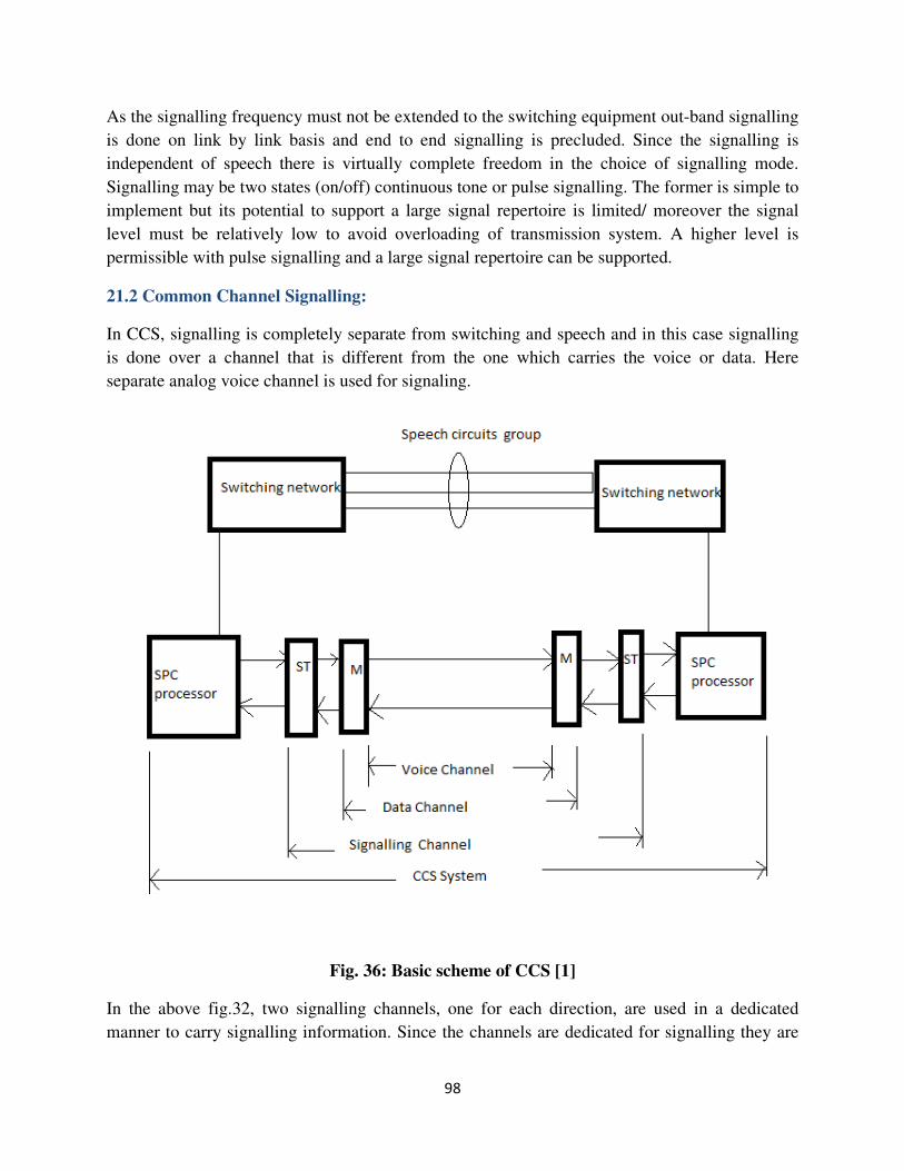
98
As the signalling frequency must not be extended to the switching equipment out-band signalling
is done on link by link basis and end to end signalling is precluded. Since the signalling is
independent of speech there is virtually complete freedom in the choice of signalling mode.
Signalling may be two states (on/off) continuous tone or pulse signalling. The former is simple to
implement but its potential to support a large signal repertoire is limited/ moreover the signal
level must be relatively low to avoid overloading of transmission system. A higher level is
permissible with pulse signalling and a large signal repertoire can be supported.
21.2 Common Channel Signalling:
In CCS, signalling is completely separate from switching and speech and in this case signalling
is done over a channel that is different from the one which carries the voice or data. Here
separate analog voice channel is used for signaling.
Fig. 36: Basic scheme of CCS [1]
In the above fig.32, two signalling channels, one for each direction, are used in a dedicated
manner to carry signalling information. Since the channels are dedicated for signalling they are
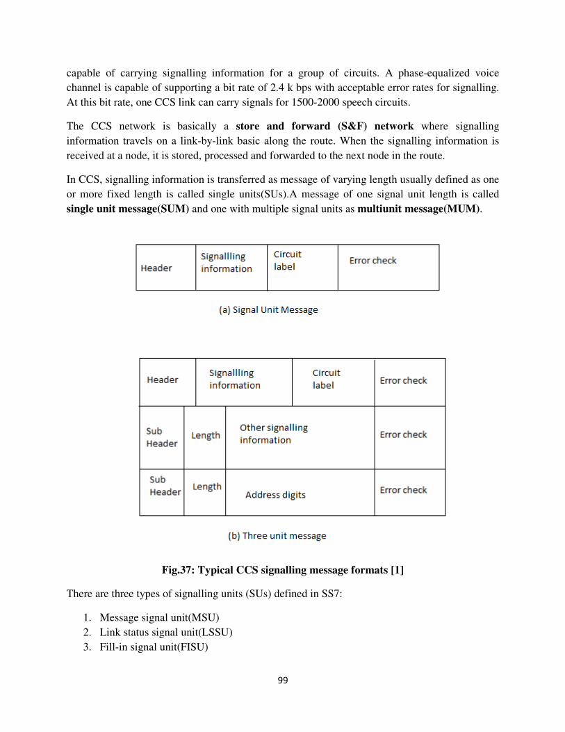
99
capable of carrying signalling information for a group of circuits. A phase-equalized voice
channel is capable of supporting a bit rate of 2.4 k bps with acceptable error rates for signalling.
At this bit rate, one CCS link can carry signals for 1500-2000 speech circuits.
The CCS network is basically a store and forward (S&F) network where signalling
information travels on a link-by-link basic along the route. When the signalling information is
received at a node, it is stored, processed and forwarded to the next node in the route.
In CCS, signalling information is transferred as message of varying length usually defined as one
or more fixed length is called single units(SUs).A message of one signal unit length is called
single unit message(SUM) and one with multiple signal units as multiunit message(MUM).
Fig.37: Typical CCS signalling message formats [1]
There are three types of signalling units (SUs) defined in SS7:
1. Message signal unit(MSU)
2. Link status signal unit(LSSU)
3. Fill-in signal unit(FISU)
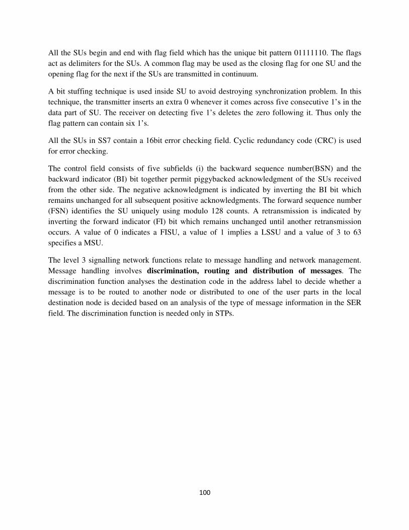
100
All the SUs begin and end with flag field which has the unique bit pattern 01111110. The flags
act as delimiters for the SUs. A common flag may be used as the closing flag for one SU and the
opening flag for the next if the SUs are transmitted in continuum.
A bit stuffing technique is used inside SU to avoid destroying synchronization problem. In this
technique, the transmitter inserts an extra 0 whenever it comes across five consecutive 1’s in the
data part of SU. The receiver on detecting five 1’s deletes the zero following it. Thus only the
flag pattern can contain six 1’s.
All the SUs in SS7 contain a 16bit error checking field. Cyclic redundancy code (CRC) is used
for error checking.
The control field consists of five subfields (i) the backward sequence number(BSN) and the
backward indicator (BI) bit together permit piggybacked acknowledgment of the SUs received
from the other side. The negative acknowledgment is indicated by inverting the BI bit which
remains unchanged for all subsequent positive acknowledgments. The forward sequence number
(FSN) identifies the SU uniquely using modulo 128 counts. A retransmission is indicated by
inverting the forward indicator (FI) bit which remains unchanged until another retransmission
occurs. A value of 0 indicates a FISU, a value of 1 implies a LSSU and a value of 3 to 63
specifies a MSU.
The level 3 signalling network functions relate to message handling and network management.
Message handling involves discrimination, routing and distribution of messages. The
discrimination function analyses the destination code in the address label to decide whether a
message is to be routed to another node or distributed to one of the user parts in the local
destination node is decided based on an analysis of the type of message information in the SER
field. The discrimination function is needed only in STPs.
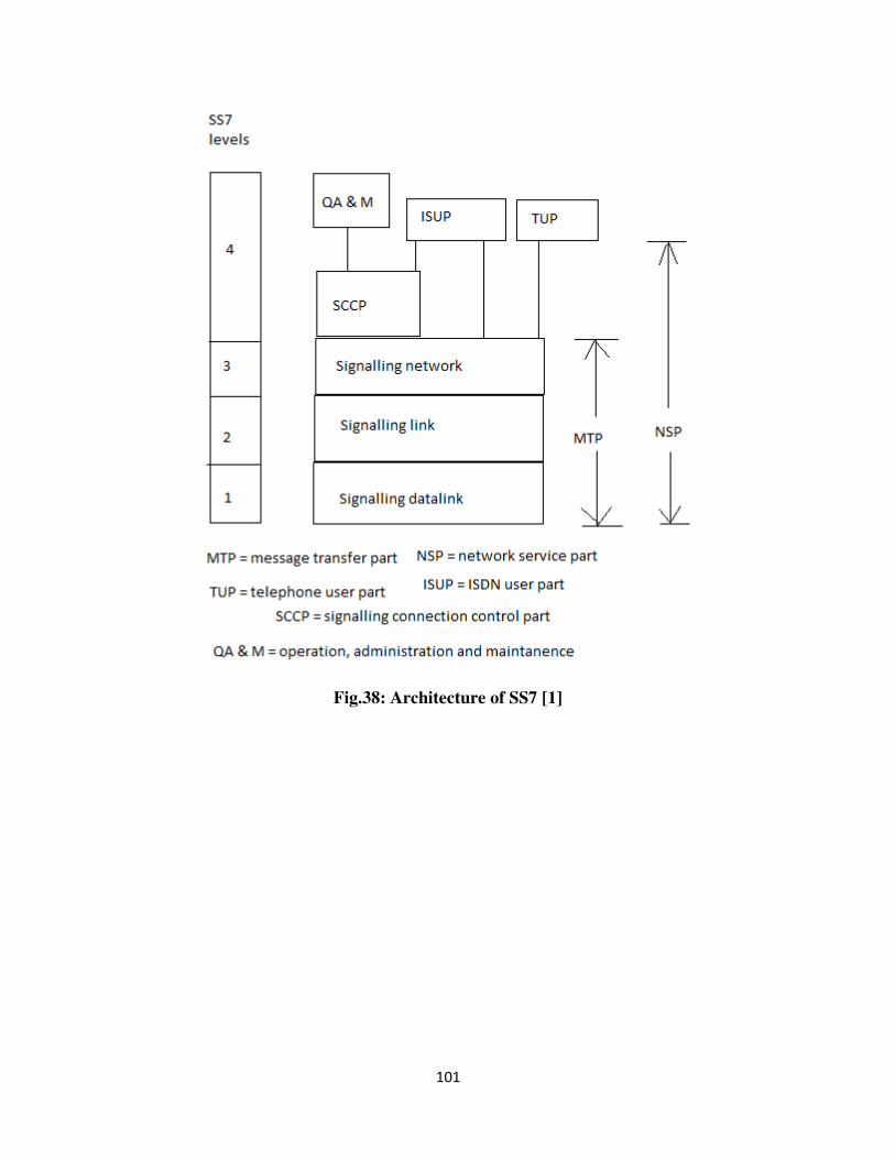
101
Fig.38: Architecture of SS7 [1]
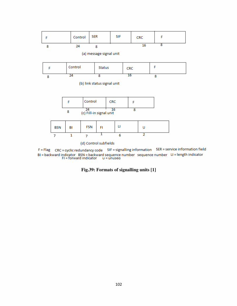
102
Fig.39: Formats of signalling units [1]
103
Objective of the Module- III:
• Transmission of different types of data through public
switched telephone network.
• Architecture of data communication.
• Data networks through satellite.
• Overview of standards that use data network.
• Overview of standards that use integrated service
digital network (ISDN).
• Concepts of broadband ISDN.
• Concepts of voice and data integration.
• Quality of service requirements in ISDN network.
• Transmission channels used in ISDN
• Different types of signalling that are used in ISDN
network.
• Different types of service characteristics that are used in
ISDN network.
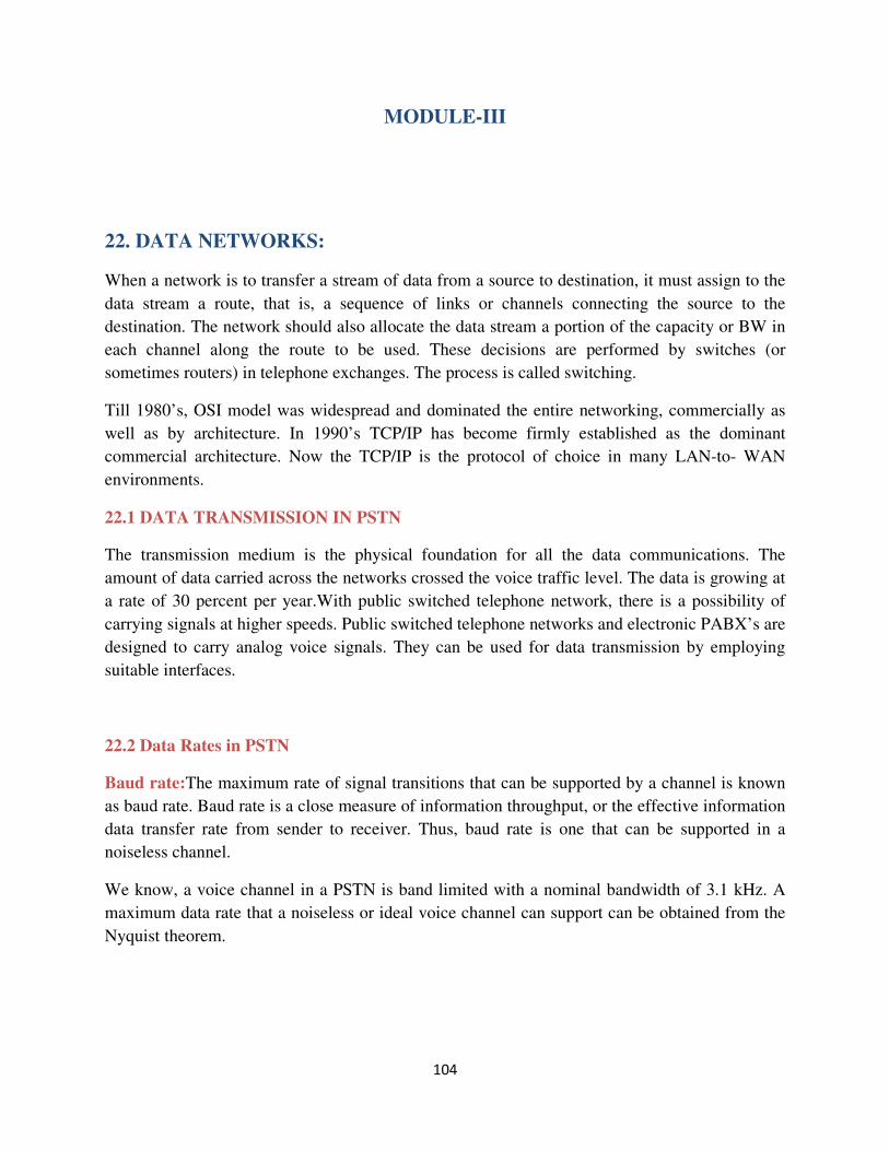
104
MODULE-III
22. DATA NETWORKS:
When a network is to transfer a stream of data from a source to destination, it must assign to the
data stream a route, that is, a sequence of links or channels connecting the source to the
destination. The network should also allocate the data stream a portion of the capacity or BW in
each channel along the route to be used. These decisions are performed by switches (or
sometimes routers) in telephone exchanges. The process is called switching.
Till 1980’s, OSI model was widespread and dominated the entire networking, commercially as
well as by architecture. In 1990’s TCP/IP has become firmly established as the dominant
commercial architecture. Now the TCP/IP is the protocol of choice in many LAN-to- WAN
environments.
22.1 DATA TRANSMISSION IN PSTN
The transmission medium is the physical foundation for all the data communications. The
amount of data carried across the networks crossed the voice traffic level. The data is growing at
a rate of 30 percent per year.With public switched telephone network, there is a possibility of
carrying signals at higher speeds. Public switched telephone networks and electronic PABX’s are
designed to carry analog voice signals. They can be used for data transmission by employing
suitable interfaces.
22.2 Data Rates in PSTN
Baud rate:The maximum rate of signal transitions that can be supported by a channel is known
as baud rate. Baud rate is a close measure of information throughput, or the effective information
data transfer rate from sender to receiver. Thus, baud rate is one that can be supported in a
noiseless channel.
We know, a voice channel in a PSTN is band limited with a nominal bandwidth of 3.1 kHz. A
maximum data rate that a noiseless or ideal voice channel can support can be obtained from the
Nyquist theorem.
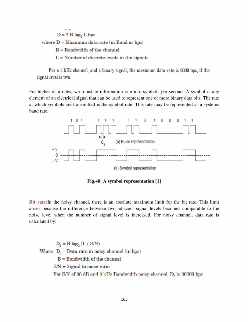
105
For higher data rates, we translate information rate into symbols per second. A symbol is any
element of an electrical signal that can be used to represent one or more binary data bits. The rate
at which symbols are transmitted is the symbol rate. This rate may be represented as a systems
baud rate.
Fig.40: A symbol representation [1]
Bit rate:In the noisy channel, there is an absolute maximum limit for the bit rate. This limit
arises because the difference between two adjacent signal levels becomes comparable to the
noise level when the number of signal level is increased. For noisy channel, data rate is
calculated by:
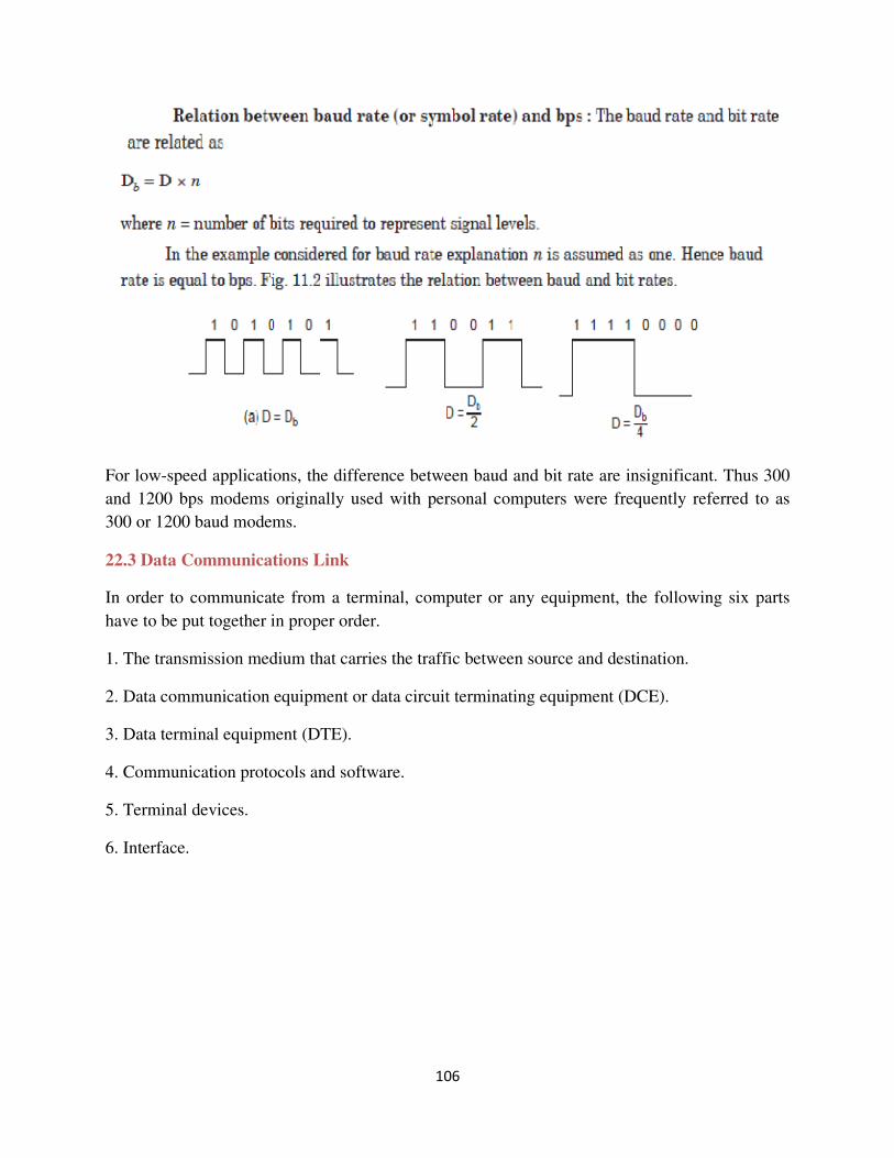
106
For low-speed applications, the difference between baud and bit rate are insignificant. Thus 300
and 1200 bps modems originally used with personal computers were frequently referred to as
300 or 1200 baud modems.
22.3 Data Communications Link
In order to communicate from a terminal, computer or any equipment, the following six parts
have to be put together in proper order.
1. The transmission medium that carries the traffic between source and destination.
2. Data communication equipment or data circuit terminating equipment (DCE).
3. Data terminal equipment (DTE).
4. Communication protocols and software.
5. Terminal devices.
6. Interface.
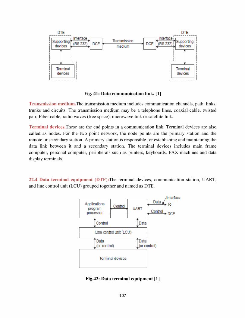
107
Fig. 41: Data communication link. [1]
Transmission medium.The transmission medium includes communication channels, path, links,
trunks and circuits. The transmission medium may be a telephone lines, coaxial cable, twisted
pair, Fiber cable, radio waves (free space), microwave link or satellite link.
Terminal devices.These are the end points in a communication link. Terminal devices are also
called as nodes. For the two point network, the node points are the primary station and the
remote or secondary station. A primary station is responsible for establishing and maintaining the
data link between it and a secondary station. The terminal devices includes main frame
computer, personal computer, peripherals such as printers, keyboards, FAX machines and data
display terminals.
22.4 Data terminal equipment (DTF):The terminal devices, communication station, UART,
and line control unit (LCU) grouped together and named as DTE.
Fig.42: Data terminal equipment [1]
108
UART.The universal asynchronous receiver transmitter (UART) and the universal
synchronous/asynchronous receiver transmitter (USART) perform the parallel to serial
conversion (and vice versa at the receiving station).
Application program processor. An application program used by the DTE, called a protocol,
defines a set of rules that determine requirements for the successful establishment of a data link
and the transfer of actual information between stations. Protocols are key components of
communication architectures. Protocols provide the rules for communication between
counterpart components on different devices. The application programs also direct control
information to the line control unit and UART to allow data flow from the peripheral currently
serviced by the LCU to the UART and out to the DCE.
Line control unit (LCU).Data sent from one station to another usually originates in parallel
binary form from one or more peripheral devices connected to that station through a LCU. The
unit acts as an interface between terminal devices and UART and the application programme
processor.
Interface.RS 232 interface is used to connect UART and the DCE. The RS-232 interface defines
the electrical function of the pins and the mechanical function of the connector. The Electrical
Industry Association (EIA) revised RS-232 C in 1989 and called the revision RS-232 D
(connector with 25 pins). RS-232 is a standard connection for serial communication. All modems
use RS 232 connections and all PCS have a RS 232 port.
Data communication equipment (DCE).The DCE is a modem. This device is used to convert
the serial data stream into a form which is suitable for transmission. This serial data stream
transferred through a transmission medium. At the receiver side, the serial data stream are
converted back to digital and sent to DTE. DCE may be a modem or a computer based node in a
data network.
23. SWITCHING TECHNIQUES:
This section describes various techniques used to establish connections between user exchanges.
Switches are hardware and/or software devices used to connect two or more users temporarily.
Message switching, circuit switching and packet switching are the most important switching
methods. The terminals of the message switching systems are usually teleprinters. In this
switching, delays are incurred but no calls are lost as each messageis queued for each link.
Thus much higher link utilization is achieved. The reason for the delay is that the system is
designed to maximize the utilization of transmission links by queuing message awaiting the use

109
of a line. This switching is also called store and forward switching. The circuit switching sets up
connection between the telephones, telex networks etc. which interchange information directly.
If a subscriber or system to which connection to be made as engaged with other connection, path
setup cannot be made. Thus circuit switching is also referred as lost call system. The modified
form of message switching is called packet switching. Packet switching system carries data from
a terminal or computer as short packets of information to the required destination.
23.1 Message Switching
In message switching, the messages are stored and relayed from secondary storage. So, message
switching is best known by the term store and forward. In message switching, there is no direct
link between the sender and the receiver. A message delivered to the destination is rerouted
along any path before it reaches the destination. It was common in 1960’s and 1970’s.
Fig.43: Message switching network.[1]
Message switching offers the possibility of greatly improved economy. The working of message
switching is as follows. Source sends message M1 to the destination. Suppose that the
transmission path selected is A––C––D. In message switching no complete connection is
required. Thus the each message includes a header contains the destination address, routing
information and priority information (for special cases).
23.2 Circuit Switching:
Circuit switching creates a direct physical connection between two devices such as phones or
computers. In order to setup a direct connection over many links it is necessary that each link to
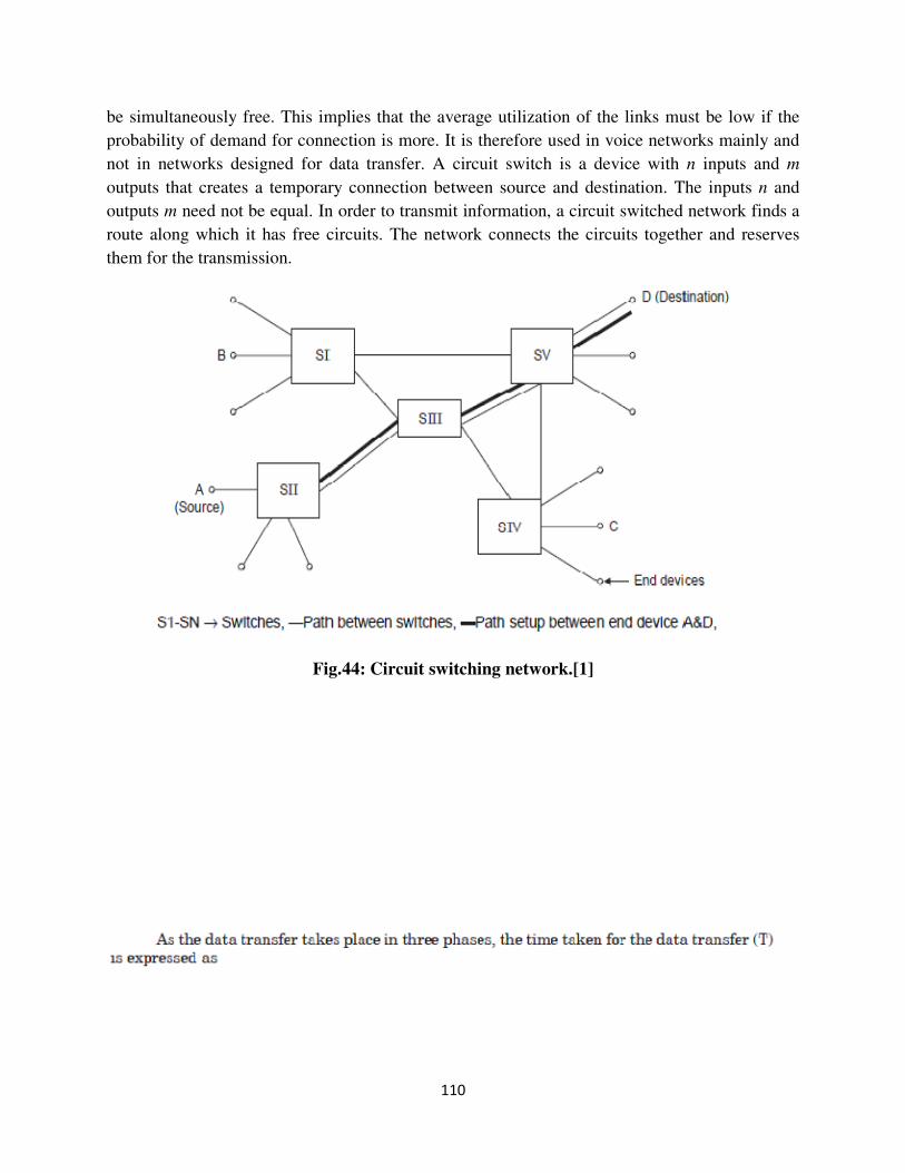
110
be simultaneously free. This implies that the average utilization of the links must be low if the
probability of demand for connection is more. It is therefore used in voice networks mainly and
not in networks designed for data transfer. A circuit switch is a device with n inputs and m
outputs that creates a temporary connection between source and destination. The inputs n and
outputs m need not be equal. In order to transmit information, a circuit switched network finds a
route along which it has free circuits. The network connects the circuits together and reserves
them for the transmission.
Fig.44: Circuit switching network.[1]
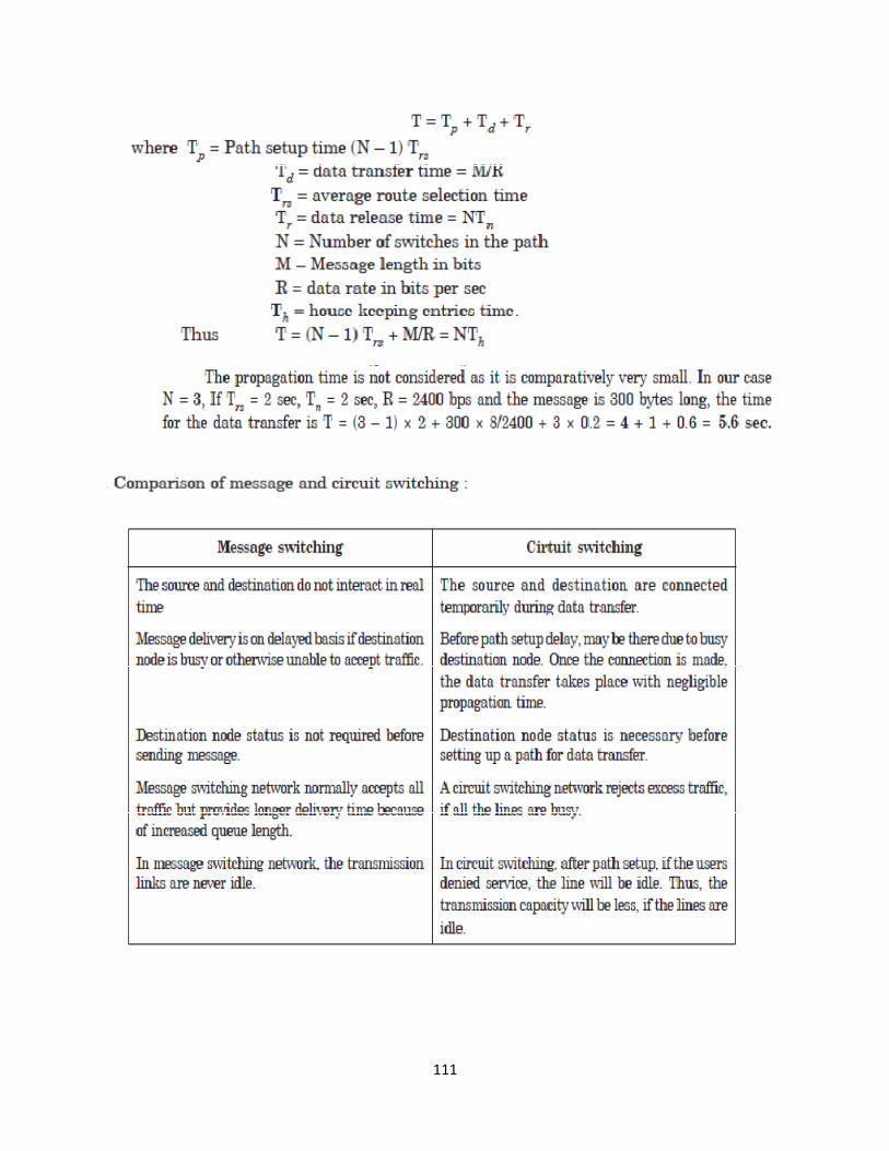
111
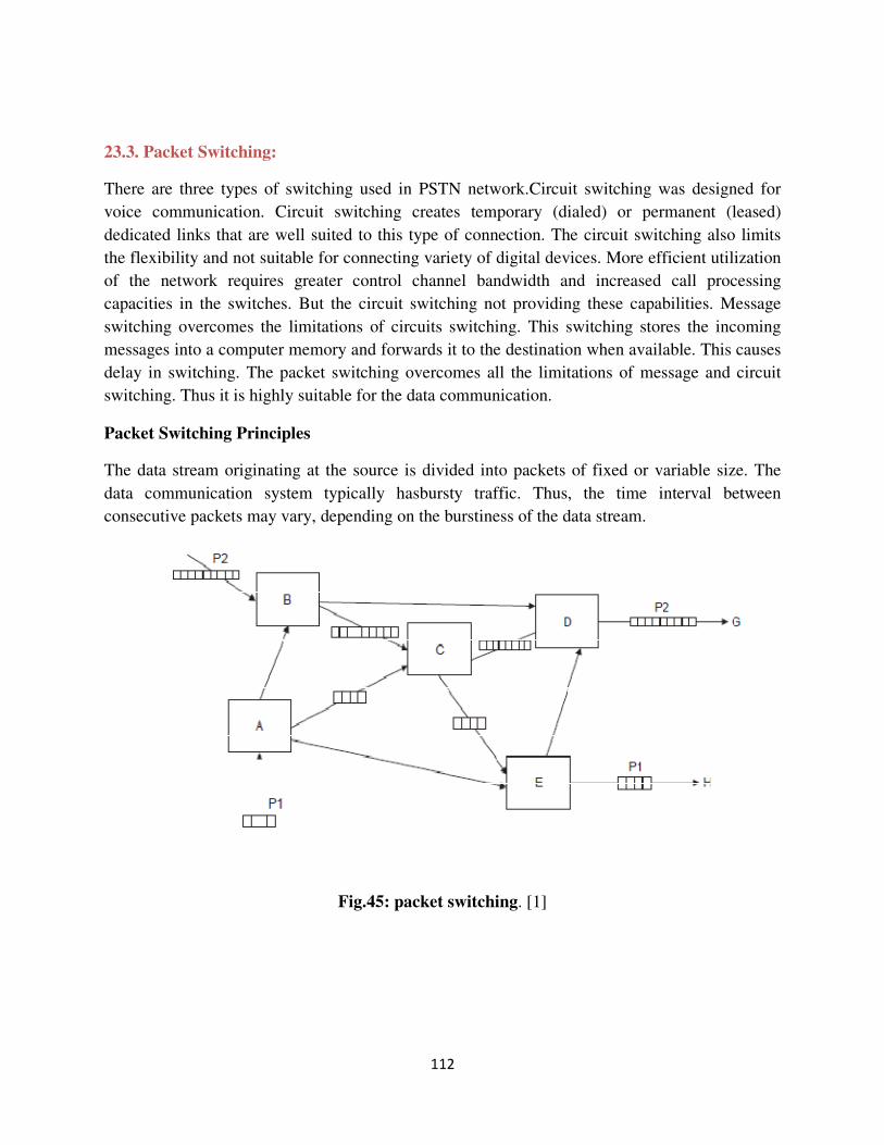
112
23.3. Packet Switching:
There are three types of switching used in PSTN network.Circuit switching was designed for
voice communication. Circuit switching creates temporary (dialed) or permanent (leased)
dedicated links that are well suited to this type of connection. The circuit switching also limits
the flexibility and not suitable for connecting variety of digital devices. More efficient utilization
of the network requires greater control channel bandwidth and increased call processing
capacities in the switches. But the circuit switching not providing these capabilities. Message
switching overcomes the limitations of circuits switching. This switching stores the incoming
messages into a computer memory and forwards it to the destination when available. This causes
delay in switching. The packet switching overcomes all the limitations of message and circuit
switching. Thus it is highly suitable for the data communication.
Packet Switching Principles
The data stream originating at the source is divided into packets of fixed or variable size. The
data communication system typically hasbursty traffic. Thus, the time interval between
consecutive packets may vary, depending on the burstiness of the data stream.
Fig.45: packet switching. [1]
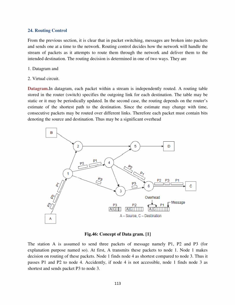
113
24. Routing Control
From the previous section, it is clear that in packet switching, messages are broken into packets
and sends one at a time to the network. Routing control decides how the network will handle the
stream of packets as it attempts to route them through the network and deliver them to the
intended destination. The routing decision is determined in one of two ways. They are
1. Datagram and
2. Virtual circuit.
Datagram.In datagram, each packet within a stream is independently routed. A routing table
stored in the router (switch) specifies the outgoing link for each destination. The table may be
static or it may be periodically updated. In the second case, the routing depends on the router’s
estimate of the shortest path to the destination. Since the estimate may change with time,
consecutive packets may be routed over different links. Therefore each packet must contain bits
denoting the source and destination. Thus may be a significant overhead
Fig.46: Concept of Data gram. [1]
The station A is assumed to send three packets of message namely P1, P2 and P3 (for
explanation purpose named so). At first, A transmits these packets to node 1. Node 1 makes
decision on routing of these packets. Node 1 finds node 4 as shortest compared to node 3. Thus it
passes P1 and P2 to node 4. Accidently, if node 4 is not accessible, node 1 finds node 3 as
shortest and sends packet P3 to node 3.
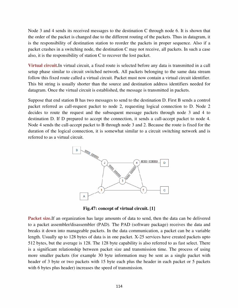
114
Node 3 and 4 sends its received messages to the destination C through node 6. It is shown that
the order of the packet is changed due to the different routing of the packets. Thus in datagram, it
is the responsibility of destination station to reorder the packets in proper sequence. Also if a
packet crashes in a switching node, the destination C may not receive, all packets. In such a case
also, it is the responsibility of station C to recover the lost packet.
Virtual circuit.In virtual circuit, a fixed route is selected before any data is transmitted in a call
setup phase similar to circuit switched network. All packets belonging to the same data stream
follow this fixed route called a virtual circuit. Packet must now contain a virtual circuit identifier.
This bit string is usually shorter than the source and destination address identifiers needed for
datagram. Once the virtual circuit is established, the message is transmitted in packets.
Suppose that end station B has two messages to send to the destination D. First B sends a control
packet referred as call-request packet to node 2, requesting logical connection to D. Node 2
decides to route the request and the subsequent message packets through node 3 and 4 to
destination D. If D prepared to accept the connection, it sends a call-accept packet to node 4.
Node 4 sends the call-accept packet to B through node 3 and 2. Because the route is fixed for the
duration of the logical connection, it is somewhat similar to a circuit switching network and is
referred to as a virtual circuit.
Fig.47: concept of virtual circuit. [1]
Packet size.If an organization has large amounts of data to send, then the data can be delivered
to a packet assembler/disassembler (PAD). The PAD (software package) receives the data and
breaks it down into manageable packets. In the data communication, a packet can be a variable
length. Usually up to 128 bytes of data is in one packet. X-25 services have created packets upto
512 bytes, but the average is 128. The 128 byte capability is also referred to as fast select. There
is a significant relationship between packet size and transmission time. The process of using
more smaller packets (for example 30 byte information may be sent as a single packet with
header of 3 byte or two packets with 15 byte each plus the header in each packet or 5 packets
with 6 bytes plus header) increases the speed of transmission.
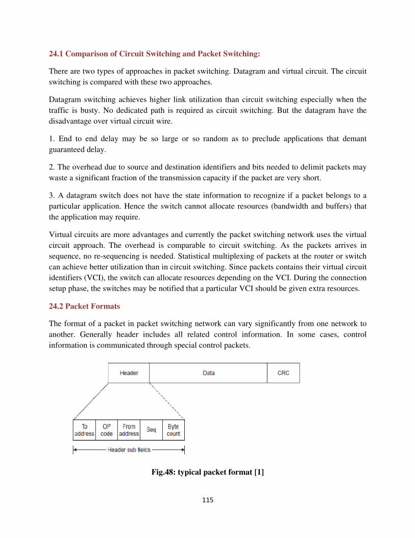
115
24.1 Comparison of Circuit Switching and Packet Switching:
There are two types of approaches in packet switching. Datagram and virtual circuit. The circuit
switching is compared with these two approaches.
Datagram switching achieves higher link utilization than circuit switching especially when the
traffic is busty. No dedicated path is required as circuit switching. But the datagram have the
disadvantage over virtual circuit wire.
1. End to end delay may be so large or so random as to preclude applications that demant
guaranteed delay.
2. The overhead due to source and destination identifiers and bits needed to delimit packets may
waste a significant fraction of the transmission capacity if the packet are very short.
3. A datagram switch does not have the state information to recognize if a packet belongs to a
particular application. Hence the switch cannot allocate resources (bandwidth and buffers) that
the application may require.
Virtual circuits are more advantages and currently the packet switching network uses the virtual
circuit approach. The overhead is comparable to circuit switching. As the packets arrives in
sequence, no re-sequencing is needed. Statistical multiplexing of packets at the router or switch
can achieve better utilization than in circuit switching. Since packets contains their virtual circuit
identifiers (VCI), the switch can allocate resources depending on the VCI. During the connection
setup phase, the switches may be notified that a particular VCI should be given extra resources.
24.2 Packet Formats
The format of a packet in packet switching network can vary significantly from one network to
another. Generally header includes all related control information. In some cases, control
information is communicated through special control packets.
Fig.48: typical packet format [1]
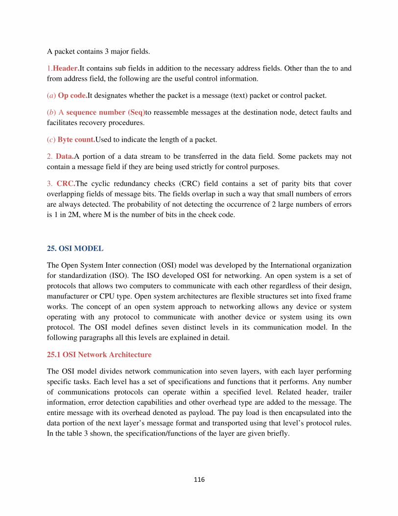
116
A packet contains 3 major fields.
1.Header.It contains sub fields in addition to the necessary address fields. Other than the to and
from address field, the following are the useful control information.
(a) Op code.It designates whether the packet is a message (text) packet or control packet.
(b) A sequence number (Seq)to reassemble messages at the destination node, detect faults and
facilitates recovery procedures.
(c) Byte count.Used to indicate the length of a packet.
2. Data.A portion of a data stream to be transferred in the data field. Some packets may not
contain a message field if they are being used strictly for control purposes.
3. CRC.The cyclic redundancy checks (CRC) field contains a set of parity bits that cover
overlapping fields of message bits. The fields overlap in such a way that small numbers of errors
are always detected. The probability of not detecting the occurrence of 2 large numbers of errors
is 1 in 2M, where M is the number of bits in the cheek code.
25. OSI MODEL
The Open System Inter connection (OSI) model was developed by the International organization
for standardization (ISO). The ISO developed OSI for networking. An open system is a set of
protocols that allows two computers to communicate with each other regardless of their design,
manufacturer or CPU type. Open system architectures are flexible structures set into fixed frame
works. The concept of an open system approach to networking allows any device or system
operating with any protocol to communicate with another device or system using its own
protocol. The OSI model defines seven distinct levels in its communication model. In the
following paragraphs all this levels are explained in detail.
25.1 OSI Network Architecture
The OSI model divides network communication into seven layers, with each layer performing
specific tasks. Each level has a set of specifications and functions that it performs. Any number
of communications protocols can operate within a specified level. Related header, trailer
information, error detection capabilities and other overhead type are added to the message. The
entire message with its overhead denoted as payload. The pay load is then encapsulated into the
data portion of the next layer’s message format and transported using that level’s protocol rules.
In the table 3 shown, the specification/functions of the layer are given briefly.
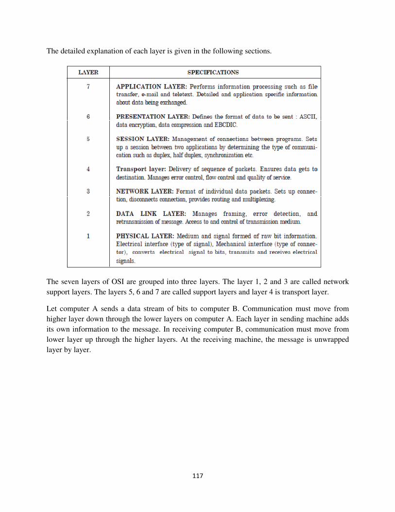
117
The detailed explanation of each layer is given in the following sections.
The seven layers of OSI are grouped into three layers. The layer 1, 2 and 3 are called network
support layers. The layers 5, 6 and 7 are called support layers and layer 4 is transport layer.
Let computer A sends a data stream of bits to computer B. Communication must move from
higher layer down through the lower layers on computer A. Each layer in sending machine adds
its own information to the message. In receiving computer B, communication must move from
lower layer up through the higher layers. At the receiving machine, the message is unwrapped
layer by layer.
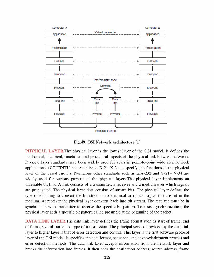
118
Fig.49: OSI Network architecture [1]
PHYSICAL LAYER.The physical layer is the lowest layer of the OSI model. It defines the
mechanical, electrical, functional and procedural aspects of the physical link between networks.
Physical layer standards have been widely used for years in point-to-point wide area network
applications. (CCITT/ITU has established X-21–X-24 to specify the functions at the physical
level of the based circuits. Numerous other standards such as EIA-232 and V-21– V-34 are
widely used for various purpose at the physical layers.The physical layer implements an
unreliable bit link. A link consists of a transmitter, a receiver and a medium over which signals
are propagated. The physical layer data consists of stream bits. The physical layer defines the
type of encoding to convert the bit stream into electrical or optical signal to transmit in the
medium. At receiver the physical layer converts back into bit stream. The receiver must be in
synchronism with transmitter to receive the specific bit pattern. To assist synchronization, the
physical layer adds a specific bit pattern called preamble at the beginning of the packet.
DATA LINK LAYER.The data link layer defines the frame format such as start of frame, end
of frame, size of frame and type of transmission. The principal service provided by the data link
layer to higher layer is that of error detection and control. This layer is the first software protocol
layer of the OSI model. It specifies the data format, sequence, and acknowledgement process and
error detection methods. The data link layer accepts information from the network layer and
breaks the information into frames. It then adds the destination address, source address, frame
119
check sequence (FCS) field and length field to each frame and passes each frame to the physical
layer for transmission on the receiving side, the data link layer accepts the bits from the physical
layer and from them into frame, performing error detection. If the frame is free of error, the data
link layer passes the frame up to the network layer. It performs frame synchronization, that is, it
identifies the beginning and end of each frame. Existing protocols for the data link layer are :
1. Synchronous Data Link Control (SDLC).Developed by IBM as link access for System
Network Architecture.
2. High Level Data Link Control (HDLC).It is a version of SDLC modified by the ISO for use
in the OSI model.
3. Link Access Procedure Balanced (LAPB).The modified version of HDLC is LAPB.
The data link layer also performs the flow control and access control. By flow control, if the rate
at which the data are absorbed by the receiver is less than the rate produced in the sender, the
data link layer imposes a flow control mechanism to prevent overwhelming the receiver. By
access control, when two or more devices are connected to the same link, the protocol of data
link layer determines which device has control over the link at any given time. Two sub layers
defined in the data link are the media access control (MAC) and the logical link control (LLC)
layer. MAC performs address management function. LLC manages flow and error control,
automatic requests for retransmission (APQ) and handshake processes
NETWORK LAYER.If two systems are attached to different networks (links) with connecting
devices between the networks (links), there is often a need for the network layer to accomplish
source to destination delivery. Thus the function of the network layer is to perform routing. The
network layer checks the logical address of each frame and forwards the frame to the next router
based on a look up table. The network layer is responsible for translating each logic address
(name address) to a physical address (MAC address).
TRANSPORT LAYER
The transport layer provides a mechanism for the exchange of data between end systems. It
optimizes the use of network services with providing a requested quality of service to session
entities. The size and complexity of a transport protocol depend on how reliable or unreliable the
underlying network and network layer services are. Essentially, this layer is responsible for the
reliable data transfer between two end nodes and is sometimes referred to as host-tohost layer.
SUPPORT LAYERS
The session layer, presentation layer and application layer are considered as support layers. All
these layers explained in the following paragraphs.
120
SESSION LAYER.The session layer establishes a logical connection between the applications
of two computers that are communicating with each other. The session layer concerns file
management and overall networking functions. Access availability and system time allocations
are included in this layer. The session layer can partition a transfer of a large number of
messages by inserting synchronous points. Specific responsibilities of the session layers are
authentication of user access, fault recovery if a break in service occurs, permitting multiple
applications to share a virtual circuit, connection and disconnection of any node from the
network.
PRESENTATION LAYER.The presentation layer receives information from theapplication
layer and converts into ASCII or Unicode or encrypts or decrypts. This layer isconcerned with
the syntax and semantics of the information exchanged between two systems.
The three basic forms of protocols used in the presentation layer are
1. Virtual terminal protocol, which is used to allow different types of terminals to support
different applications.
2. Virtual file protocol, which handles code conversions’ within files, file communication and
file formatting.
3. Job transfer and manipulating protocols which controls the structure of jobs andrecords.
A separate protocol function known as abstract syntax notation (ASN) specifies file
datastructure.
APPLICATION LAYER.This layer enables users to access the network with applications such
as e-mail, FTP and Telnet. It provides user interfaces and support for various services. Specific
services are (a) Network virtual terminal (b) File transfer access and management (FTAM), (c)
Mail services (d) Directory services (e) Specific User Service Element (SUSE) — deals with
actual user requirements for access and use of the network (f) Common application service
element (CASE) — This sets guidelines for the applications required quality of service and (g)
Specific application service element (SASE) — deals with large amount of data, including
database access.
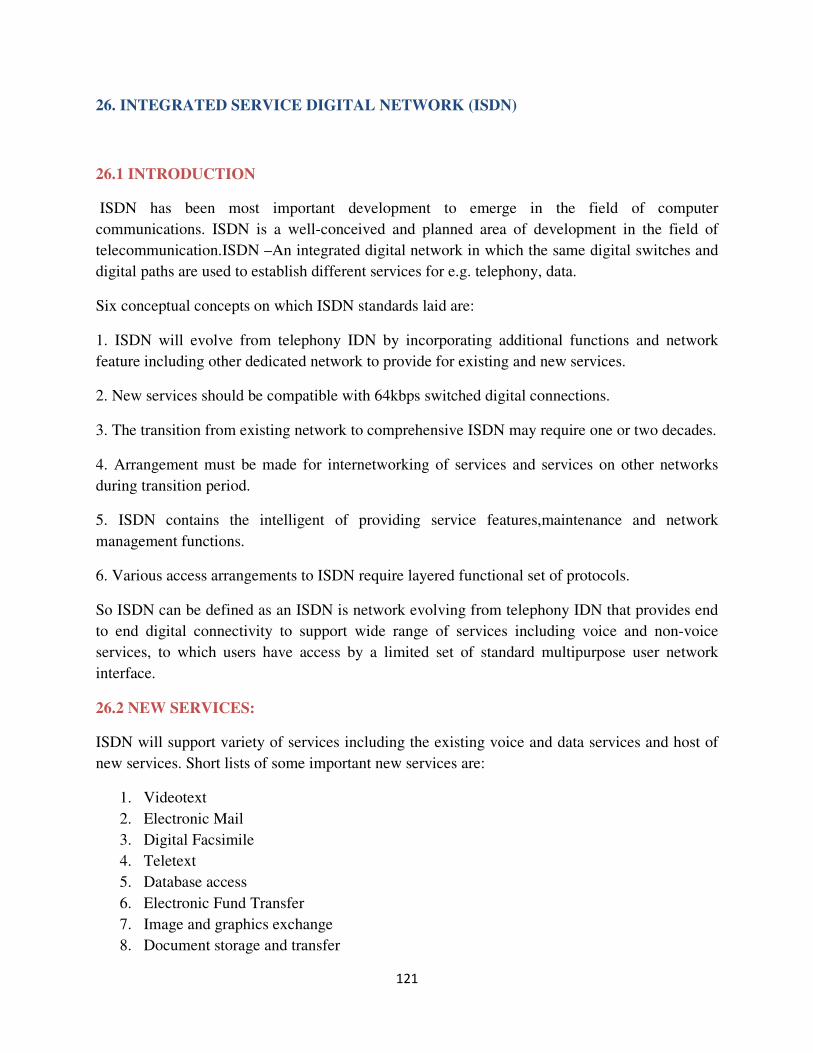
121
26. INTEGRATED SERVICE DIGITAL NETWORK (ISDN)
26.1 INTRODUCTION
ISDN has been most important development to emerge in the field of computer
communications. ISDN is a well-conceived and planned area of development in the field of
telecommunication.ISDN –An integrated digital network in which the same digital switches and
digital paths are used to establish different services for e.g. telephony, data.
Six conceptual concepts on which ISDN standards laid are:
1. ISDN will evolve from telephony IDN by incorporating additional functions and network
feature including other dedicated network to provide for existing and new services.
2. New services should be compatible with 64kbps switched digital connections.
3. The transition from existing network to comprehensive ISDN may require one or two decades.
4. Arrangement must be made for internetworking of services and services on other networks
during transition period.
5. ISDN contains the intelligent of providing service features,maintenance and network
management functions.
6. Various access arrangements to ISDN require layered functional set of protocols.
So ISDN can be defined as an ISDN is network evolving from telephony IDN that provides end
to end digital connectivity to support wide range of services including voice and non-voice
services, to which users have access by a limited set of standard multipurpose user network
interface.
26.2 NEW SERVICES:
ISDN will support variety of services including the existing voice and data services and host of
new services. Short lists of some important new services are:
1. Videotext
2. Electronic Mail
3. Digital Facsimile
4. Teletext
5. Database access
6. Electronic Fund Transfer
7. Image and graphics exchange
8. Document storage and transfer
122
9. Automatic alarm services, e.g., smoke,fire,police,medical
10. Audio and video conferencing
VIDEOTEX
Videotex is a generic term for systems that provide easy to use, low cost computer based services
via communication facilities. Three forms of videotext exist:
1. View data
2. Teletext
3. Open Channel teletext
View data is fully interactive videotex. This means that request for information and service from
a user are actually sent to, received by, and acted on by a centralized computer.
Teletex is broadcast or pseudo-interactive videotext service. Teletext users may select the
information to be seen, the pace at which the information to be displayed and, often sequence of
display. The information cast in the form of frames and set of frames which is called a magazine
is recycled continuously. Teletext is a one way communication system and there is no real
interaction between the user and the computer.
Open channel teletext is totally non-interactive one way videotext. With this form of videotext,
the user receives pre-selected information in predetermined order. There is no interaction either
real or apparent. The user has no control over the pace or sequence of display. Open channel text
may classify into three categories according to the way of preselected information displayed and
the way of display channel is used:
1. Dedicated open channel
2. Open captioning
3. Closed captioning
In dedicated open channel text, a separate transmission channel is dedicated for the display of
preselected information. Open captioning shares a normal display channel and teletext
display appears at fixed intervals along with other programs of channel.
ELECTRONIC MAIL
Electronic Mail is popularly known as email, may be defined as the communication of textual
messages via electronics means. Even the telex communication is electronic in nature but the
differences are telex communication is terminal to terminal, electronic mail communication is
user-to-user. In telex message destined to no. of users are sent to the same terminal form where it
is distributed by an operator or messenger. On the other hand electronic mail delivered to the
mail boxes of individuals. Telex works on a circuit switched mode, where electronic mail is store
and forward(S&F) services. Electronic mail is computer based message system where telex is
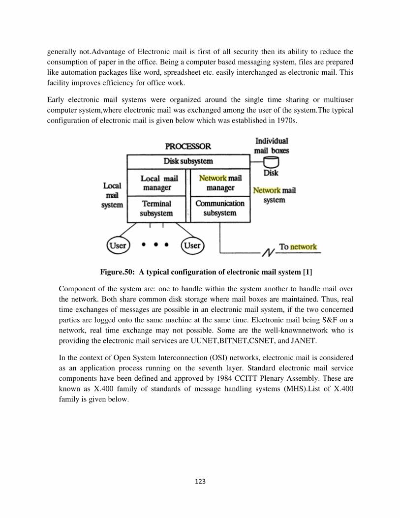
123
generally not.Advantage of Electronic mail is first of all security then its ability to reduce the
consumption of paper in the office. Being a computer based messaging system, files are prepared
like automation packages like word, spreadsheet etc. easily interchanged as electronic mail. This
facility improves efficiency for office work.
Early electronic mail systems were organized around the single time sharing or multiuser
computer system,where electronic mail was exchanged among the user of the system.The typical
configuration of electronic mail is given below which was established in 1970s.
Figure.50: A typical configuration of electronic mail system [1]
Component of the system are: one to handle within the system another to handle mail over
the network. Both share common disk storage where mail boxes are maintained. Thus, real
time exchanges of messages are possible in an electronic mail system, if the two concerned
parties are logged onto the same machine at the same time. Electronic mail being S&F on a
network, real time exchange may not possible. Some are the well-knownnetwork who is
providing the electronic mail services are UUNET,BITNET,CSNET, and JANET.
In the context of Open System Interconnection (OSI) networks, electronic mail is considered
as an application process running on the seventh layer. Standard electronic mail service
components have been defined and approved by 1984 CCITT Plenary Assembly. These are
known as X.400 family of standards of message handling systems (MHS).List of X.400
family is given below.
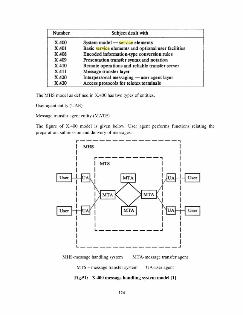
124
The MHS model as defined in X.400 has two types of entities.
User agent entity (UAE)
Message transfer agent entity (MATE)
The figure of X.400 model is given below. User agent performs functions relating the
preparation, submission and delivery of messages.
MHS-message handling system MTA-message transfer agent
MTS – message transfer system UA-user agent
Fig.51: X.400 message handling system model [1]
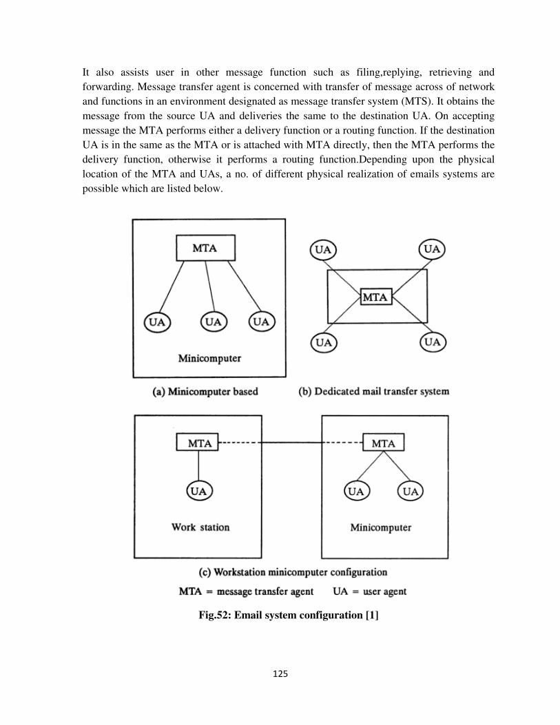
125
It also assists user in other message function such as filing,replying, retrieving and
forwarding. Message transfer agent is concerned with transfer of message across of network
and functions in an environment designated as message transfer system (MTS). It obtains the
message from the source UA and deliveries the same to the destination UA. On accepting
message the MTA performs either a delivery function or a routing function. If the destination
UA is in the same as the MTA or is attached with MTA directly, then the MTA performs the
delivery function, otherwise it performs a routing function.Depending upon the physical
location of the MTA and UAs, a no. of different physical realization of emails systems are
possible which are listed below.
Fig.52: Email system configuration [1]
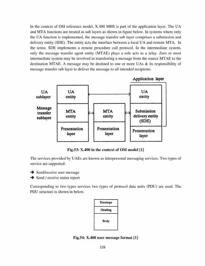
126
In the context of OSI reference model, X.400 MHS is part of the application layer. The UA
and MTA functions are treated as sub layers as shown in figure below. In systems where only
the UA function is implemented, the message transfer sub layer comprises a submission and
delivery entity (SDE). The entity acts the interface between a local UA and remote MTA. In
the sense, SDE implements a remote procedure call protocol. In the intermediate system,
only the message transfer agent entity (MTAE) plays a role acts as a relay. Zero or most
intermediate system may be involved in transferring a message from the source MTAE to the
destination MTAE. A message may be destined to one or more UAs & its responsibility of
message transfer sub layer to deliver the message to all intended recipients.
Fig.53: X.400 in the context of OSI model [1]
The services provided by UAEs are known as interpersonal messaging services. Two types of
service are supported:
� Send/receive user message
� Send / receive status report
Corresponding to two types services two types of protocol data units (PDU) are used. The
PDU structure is shown in below.
Fig.54: X.400 user message format [1]
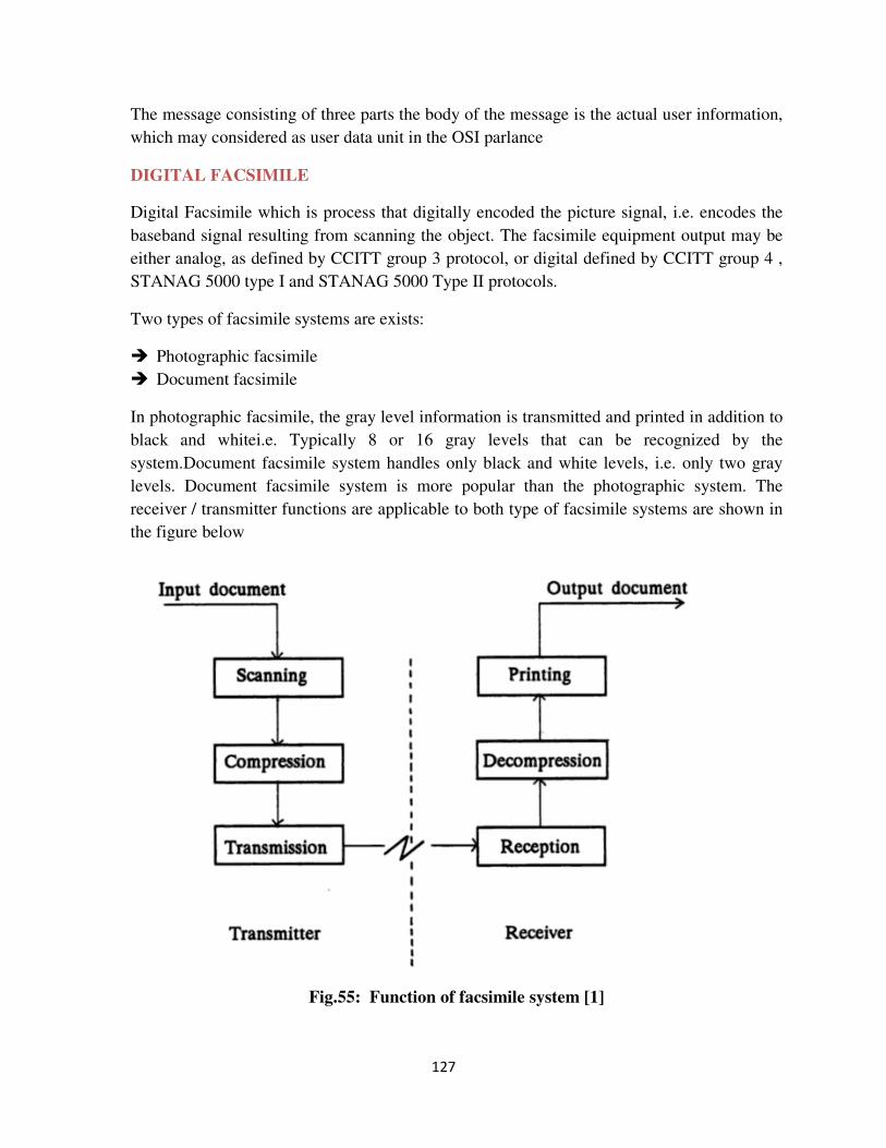
127
The message consisting of three parts the body of the message is the actual user information,
which may considered as user data unit in the OSI parlance
DIGITAL FACSIMILE
Digital Facsimile which is process that digitally encoded the picture signal, i.e. encodes the
baseband signal resulting from scanning the object. The facsimile equipment output may be
either analog, as defined by CCITT group 3 protocol, or digital defined by CCITT group 4 ,
STANAG 5000 type I and STANAG 5000 Type II protocols.
Two types of facsimile systems are exists:
� Photographic facsimile
� Document facsimile
In photographic facsimile, the gray level information is transmitted and printed in addition to
black and whitei.e. Typically 8 or 16 gray levels that can be recognized by the
system.Document facsimile system handles only black and white levels, i.e. only two gray
levels. Document facsimile system is more popular than the photographic system. The
receiver / transmitter functions are applicable to both type of facsimile systems are shown in
the figure below
Fig.55: Function of facsimile system [1]
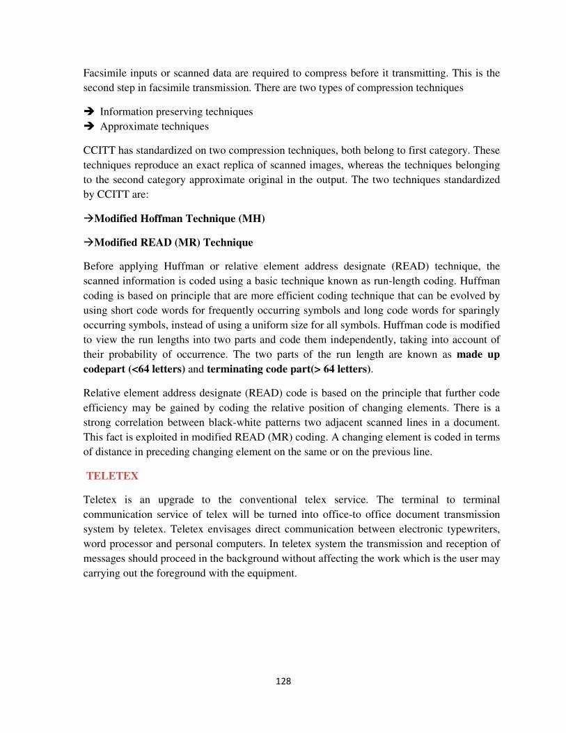
128
Facsimile inputs or scanned data are required to compress before it transmitting. This is the
second step in facsimile transmission. There are two types of compression techniques
� Information preserving techniques
� Approximate techniques
CCITT has standardized on two compression techniques, both belong to first category. These
techniques reproduce an exact replica of scanned images, whereas the techniques belonging
to the second category approximate original in the output. The two techniques standardized
by CCITT are:
�Modified Hoffman Technique (MH)
�Modified READ (MR) Technique
Before applying Huffman or relative element address designate (READ) technique, the
scanned information is coded using a basic technique known as run-length coding. Huffman
coding is based on principle that are more efficient coding technique that can be evolved by
using short code words for frequently occurring symbols and long code words for sparingly
occurring symbols, instead of using a uniform size for all symbols. Huffman code is modified
to view the run lengths into two parts and code them independently, taking into account of
their probability of occurrence. The two parts of the run length are known as made up
codepart (<64 letters) and terminating code part(> 64 letters).
Relative element address designate (READ) code is based on the principle that further code
efficiency may be gained by coding the relative position of changing elements. There is a
strong correlation between black-white patterns two adjacent scanned lines in a document.
This fact is exploited in modified READ (MR) coding. A changing element is coded in terms
of distance in preceding changing element on the same or on the previous line.
TELETEX
Teletex is an upgrade to the conventional telex service. The terminal to terminal
communication service of telex will be turned into office-to office document transmission
system by teletex. Teletex envisages direct communication between electronic typewriters,
word processor and personal computers. In teletex system the transmission and reception of
messages should proceed in the background without affecting the work which is the user may
carrying out the foreground with the equipment.
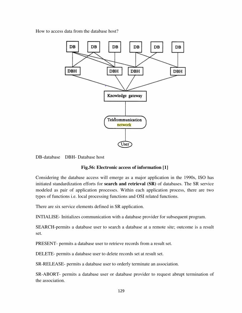
129
How to access data from the database host?
DB-database DBH- Database host
Fig.56: Electronic access of information [1]
Considering the database access will emerge as a major application in the 1990s, ISO has
initiated standardization efforts for search and retrieval (SR) of databases. The SR service
modeled as pair of application processes. Within each application process, there are two
types of functions i.e. local processing functions and OSI related functions.
There are six service elements defined in SR application.
INTIALISE- Initializes communication with a database provider for subsequent program.
SEARCH-permits a database user to search a database at a remote site; outcome is a result
set.
PRESENT- permits a database user to retrieve records from a result set.
DELETE- permits a database user to delete records set at result set.
SR-RELEASE- permits a database user to orderly terminate an association.
SR-ABORT- permits a database user or database provider to request abrupt termination of
the association.
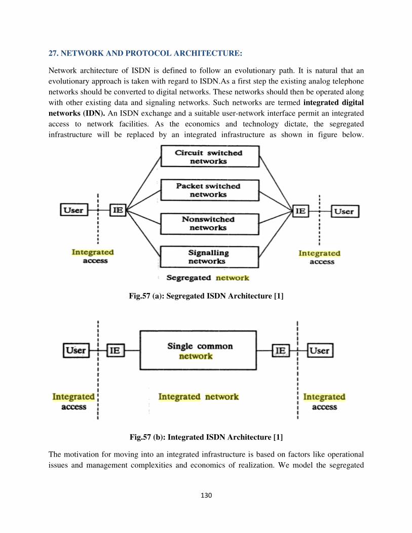
130
27. NETWORK AND PROTOCOL ARCHITECTURE:
Network architecture of ISDN is defined to follow an evolutionary path. It is natural that an
evolutionary approach is taken with regard to ISDN.As a first step the existing analog telephone
networks should be converted to digital networks. These networks should then be operated along
with other existing data and signaling networks. Such networks are termed integrated digital
networks (IDN). An ISDN exchange and a suitable user-network interface permit an integrated
access to network facilities. As the economics and technology dictate, the segregated
infrastructure will be replaced by an integrated infrastructure as shown in figure below.
Fig.57 (a): Segregated ISDN Architecture [1]
Fig.57 (b): Integrated ISDN Architecture [1]
The motivation for moving into an integrated infrastructure is based on factors like operational
issues and management complexities and economics of realization. We model the segregated
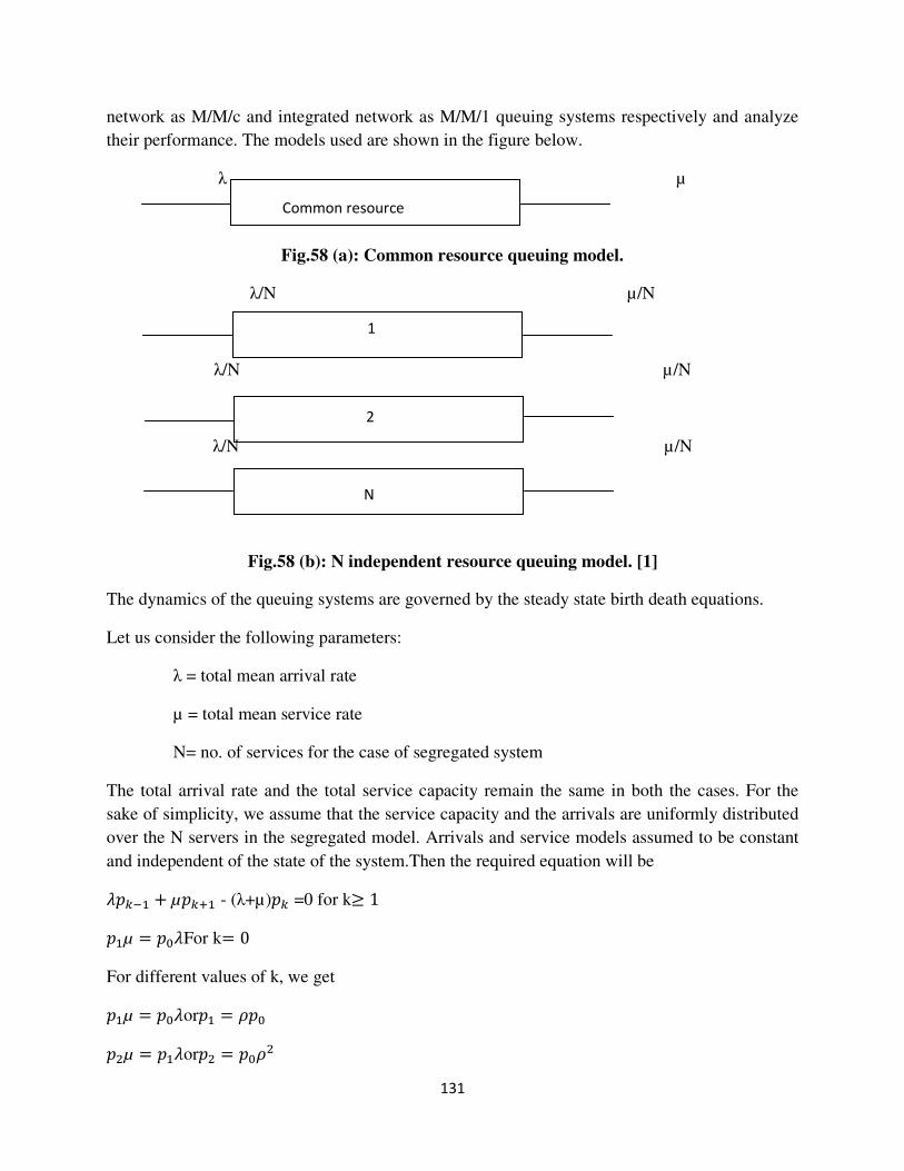
131
network as M/M/c and integrated network as M/M/1 queuing systems respectively and analyze
their performance. The models used are shown in the figure below.
λ µ
Fig.58 (a): Common resource queuing model.
λ/N µ/N
λ/N µ/N
λ/N µ/N
Fig.58 (b): N independent resource queuing model. [1]
The dynamics of the queuing systems are governed by the steady state birth death equations.
Let us consider the following parameters:
λ = total mean arrival rate
µ = total mean service rate
N= no. of services for the case of segregated system
The total arrival rate and the total service capacity remain the same in both the cases. For the
sake of simplicity, we assume that the service capacity and the arrivals are uniformly distributed
over the N servers in the segregated model. Arrivals and service models assumed to be constant
and independent of the state of the system.Then the required equation will be
�2��� + µ2�4� - (λ+µ)2� =0 for k≥ 1
2�µ = 2��For k= 0
For different values of k, we get
2�µ = 2��or2� = 52�
26µ = 2��or26 = 2�56
Common resource
1
2
N
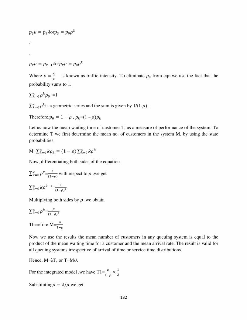
132
27µ = 26�or27 = 2�57
.
.
2�µ = 2����or2�µ = 2�5�
Where 5 = 8µ is known as traffic intensity. To eliminate 2� from eqn.we use the fact that the
probability sums to 1.
∑ 5�5�∞
�:� =1
∑ 5�∞
�:� is a geometric series and the sum is given by 1/(1-5 .
Therefore,2� = 1 − 5 , 5�=(1 – 55�
Let us now the mean waiting time of customer T, as a measure of performance of the system. To
determine T we first determine the mean no. of customers in the system M, by using the state
probabilities.
M=∑ <5� = �1 − 5∑ <5�∞
�:�∞
�:�
Now, differentiating both sides of the equation
∑ 5�∞
�:� =�
���= with respect to 5 ,we get
∑ <5���∞
�:� =�
���=>
Multiplying both sides by 5 ,we obtain
∑ 5�∞
�:� ==
���=>
Therefore M==
��=
Now we use the results the mean number of customers in any queuing system is equal to the
product of the mean waiting time for a customer and the mean arrival rate. The result is valid for
all queuing systems irrespective of arrival of time or service time distributions.
Hence, M=λT, or T=M/λ
For the integrated model ,we have T1==
��= �8
Substituting5 = �/µ,we get
133
T1=8
µ���8/µ ×�8 = �
µ�8
For the segregated system, we have
Ts=�
�µ/A��8/A =A
µ�8 = BC1
Shows the delay performance of segregated system deteriorates by N times if the integrated
system is broken into N segments with 1/Nth of the capacity of the integrated system.
1. The total capacities of the integrated and segregated networks are identical.
2. Input services are identical requirements in both the cases.
3. Services rate distributions are identical.
The protocol architecture of ISDN layer is according to the OSI reference model.ISDN is largely
concerned with the lower layers 1-3 Layers 4-7 concern of service providers. Accordingly lower
three layers are known as bearer service functions. Service offered by service providers are
known as teleservices.
Layer 1(Physical Layer)
The physical layer is the lowest layer of the OSI model. It defines the mechanical, electrical,
functional and procedural aspects of the physical link between networks. Physical layer
standards have been widely used for years in point-to-point wide area network applications.
(CCITT/ITU has established X-21–X-24 to specify the functions at the physical level of the
based circuits. Numerous other standards such as EIA-232 and V-21– V-34 are widely used for
various purposes at the physical layers. The physical layer implements an unreliable bit link. A
link consists of a transmitter, a receiver and a medium over which signals are propagated. The
physical layer data consists of stream bits. The physical layer defines the type of encoding to
convert the bit stream into electrical or optical signal to transmit in the medium. At receiver the
physical layer converts back into bit stream. The receiver must be in synchronism with
transmitter to receive the specific bit pattern. To assist synchronization, the physical layer adds a
specific bit pattern called preamble at the beginning of the packet.
Layer 2(Data Link Layer)
1. Establishing and clearing the data links
2. Error, flow and congestion control
3. Synchronization
The data link layer defines the frame format such as start of frame, end of frame, size of frame
and type of transmission. The principal service provided by the data link layer to higher layer is
that of error detection and control. This layer is the first software protocol layer of the OSI
model. It specifies the data format, sequence, and acknowledgement process and error detection

134
methods. The data link layer accepts information from the network layer and breaks the
information into frames. It then adds the destination address, source address, frame check
sequence (FCS) field and length field to each frame and passes each frame to the physical layer
for transmission on the receiving side, the data link layer accepts the bits from the physical layer
and from them into frame, performing error detection. If the frame is free of error, the data link
layer passes the frame up to the network layer. It performs frame synchronization, that is, it
identifies the beginning and end of each frame. Existing protocols for the data link layer are :
1. Synchronous Data Link Control (SDLC). Developed by IBM as link access for System
Network Architecture.
2. High Level Data Link Control (HDLC). It is a version of SDLC modified by the ISO for use
in the OSI model.
3. Link Access Procedure Balanced (LAPB). The modified version of HDLC is LAPB.
The data link layer also performs the flow control and access control. By flow control, if the rate
at which the data are absorbed by the receiver is less than the rate produced in the sender, the
data link layer imposes a flow control mechanism to prevent overwhelming the receiver. By
access control, when two or more devices are connected to the same link, the protocol of data
link layer determines which device has control over the link at any given time. Two sub layers
defined in the data link are the media access control (MAC) and the logical link control (LLC)
layer. MAC performs address management function. LLC manages flow and error control,
automatic requests for retransmission (APQ) and handshake processes
Layer 3 (Network layer)
1. Addressing and routing
2. Establishing and clearing network level connection
3. User-to-user signaling
4. Network level multiplexing
5. Internetworking Multiplexing
If two systems are attached to different networks (links) with connecting devices between the
networks (links), there is often a need for the network layer to accomplish source to destination
delivery. Thus the function of the network layer is to perform routing. The network layer checks
the logical address of each frame and forwards the frame to the next router based on a look up
table. The network layer is responsible for translating each logic address (name address) to a
physical address (MAC address).
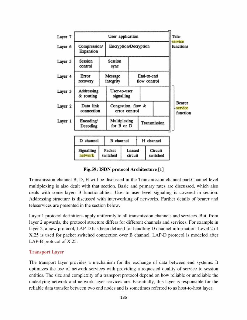
135
Fig.59: ISDN protocol Architecture [1]
Transmission channel B, D, H will be discussed in the Transmission channel part.Channel level
multiplexing is also dealt with that section. Basic and primary rates are discussed, which also
deals with some layers 3 functionalities. User-to user level signaling is covered in section.
Addressing structure is discussed with interworking of networks. Further details of bearer and
teleservices are presented in the section below.
Layer 1 protocol definitions apply uniformly to all transmission channels and services. But, from
layer 2 upwards, the protocol structure differs for different channels and services. For example in
layer 2, a new protocol, LAP-D has been defined for handling D channel information. Level 2 of
X.25 is used for packet switched connection over B channel. LAP-D protocol is modeled after
LAP-B protocol of X.25.
Transport Layer
The transport layer provides a mechanism for the exchange of data between end systems. It
optimizes the use of network services with providing a requested quality of service to session
entities. The size and complexity of a transport protocol depend on how reliable or unreliable the
underlying network and network layer services are. Essentially, this layer is responsible for the
reliable data transfer between two end nodes and is sometimes referred to as host-to-host layer.
136
Support Layers
The session layer, presentation layer and application layer are considered as support layers. All
these layers explained in the following paragraphs.
Session Layers
The session layer establishes a logical connection between the applications of two computers that
are communicating with each other. The session layer concerns file management and overall
networking functions. Access availability and system time allocations are included in this layer.
The session layer can partition a transfer of a large number of messages by inserting synchronous
points. Specific responsibilities of the session layers are authentication of user access, fault
recovery if a break in service occurs, permitting multiple applications to share a virtual circuit,
connection and disconnection of any node from the network.
Presentation Layer The presentation layer receives information from theapplication layer and converts into ASCII or
Unicode or encrypts or decrypts. This layer isconcerned with the syntax and semantics of the
information exchanged between two systems.
The three basic forms of protocols used in the presentation layer are
1. Virtual terminal protocol, which is used to allow different types of terminals to
supportdifferent applications.
2. Virtual file protocol, which handles code conversions’ within files, file communicationand file
formatting.
3. Job transfer and manipulating protocols which controls the structure of jobs andrecords.
A separate protocol function known as abstract syntax notation (ASN) specifies file
datastructure.
Application Layer.
This layer enables users to access the network with applications such as e-mail, FTP and Telnet.
It provides user interfaces and support for various services. Specific services are (a) Network
virtual terminal (b) File transfer access and management (FTAM), (c) Mail services (d) Directory
services (e) Specific User Service Element (SUSE) — deals with actual user requirements for
access and use of the network (f) Common application service element (CASE) — This sets
guidelines for the applications required quality of service and (g) Specific application service
element (SASE) — deals with large amount of data, including database access.
28. TRANSMISSION CHANNELS
In simple word transmission channel is nothing but a path between two nodes in the network. It
may refer to the physical cable, the signal transmitted within the cable or to a sub channel within
137
the carrier frequency. There are three types of fundamental channels in ISDN around which the
entire information transmission is organized. These are
� Basic information channel or B channel,64 kbps
� Signaling channel or D channel, 16 or 64 kbps
� High speed channel or H channel
These three ISDN channels are described below.
B channel (Bearer Channel):B channels are logical digital ‘‘pipes’’ which exist on a single
ISDN line. B channel carry data and services at 64 kbps. It carries data in full duplex mode. Each
B channels provide a 64 kbps clear channel, clear meaning that the entire bandwidth is available
for data, B channels typically form circuit switched connections. B channel connection is an end-
to-end physical circuit that is temporarily dedicated to transferring data between two devices.
The circuit switched nature of B channel connections; combined with their reliability and
relatively high bandwidth makes ISDN suitable for a range of applications including voice,
video, fax and data. B channels are normally used for on-demand connection. As B channel
operation based on circuit switching, it can be configured as semi-permanent or ‘‘nailed up’’
connections.
D channel (Delta Channel): D channel can be either 16 or 64 kbps, depending on the needs of
the user. The primary function of the D channel is to carry control signaling and administrative
information for B channels to set up and tear down the calls. The D channel uses packet switched
connection. The packet switched connection are best adapted to the intermittent but latency
sensitive nature of signalling traffic, accounting for the highly reduced call setup time of 1 to 2
seconds on ISDN calls. Unlike the B-channel, which can function as a simple ‘pipe’, the D
channel is associated with higher level protocols at layers 2 and 3 of OSI model which form the
packet switched connections. The D channel provides the signalling information that is required
for caller identification. It also includes low-rate data transfer and applications such as telemetry
and alarm transmission.
H channels(Hybrid Channel).H channels are suitable for high data rate applications such as
video, teleconferencing and so on. Table 4 gives ISDN channel and its specifications.
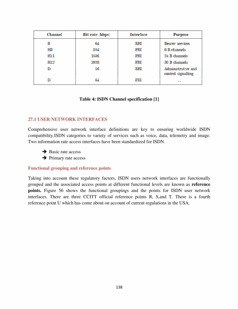
138
Table 4: ISDN Channel specification [1]
27.1 USER NETWORK INTERFACES
Comprehensive user network interface definitions are key to ensuring worldwide ISDN
compatibility.ISDN categories to variety of services such as voice, data, telemetry and image.
Two information rate access interfaces have been standardized for ISDN.
� Basic rate access
� Primary rate access
Functional grouping and reference points
Taking into account these regulatory factors, ISDN users network interfaces are functionally
grouped and the associated access points at different functional levels are known as reference
points. Figure 56 shows the functional groupings and the points for ISDN user network
interfaces. There are three CCITT official reference points R, S,and T. There is a fourth
reference point U which has come about on account of current regulations in the USA.
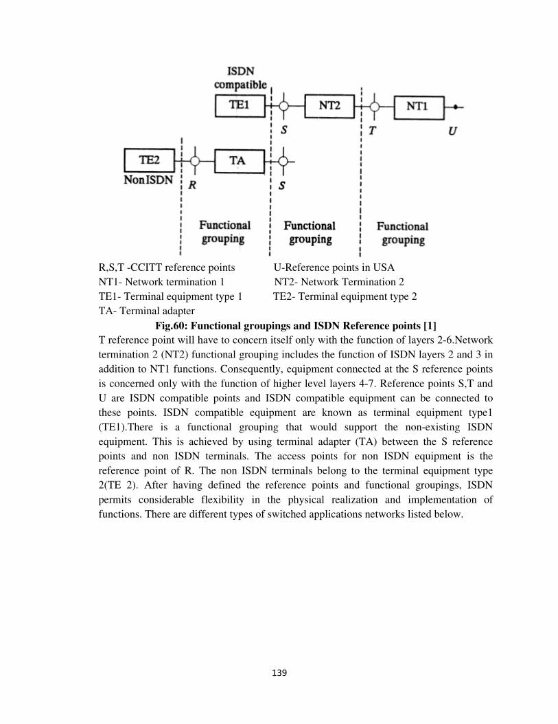
139
R,S,T -CCITT reference points U-Reference points in USA
NT1- Network termination 1 NT2- Network Termination 2
TE1- Terminal equipment type 1 TE2- Terminal equipment type 2
TA- Terminal adapter
Fig.60: Functional groupings and ISDN Reference points [1]
T reference point will have to concern itself only with the function of layers 2-6.Network
termination 2 (NT2) functional grouping includes the function of ISDN layers 2 and 3 in
addition to NT1 functions. Consequently, equipment connected at the S reference points
is concerned only with the function of higher level layers 4-7. Reference points S,T and
U are ISDN compatible points and ISDN compatible equipment can be connected to
these points. ISDN compatible equipment are known as terminal equipment type1
(TE1).There is a functional grouping that would support the non-existing ISDN
equipment. This is achieved by using terminal adapter (TA) between the S reference
points and non ISDN terminals. The access points for non ISDN equipment is the
reference point of R. The non ISDN terminals belong to the terminal equipment type
2(TE 2). After having defined the reference points and functional groupings, ISDN
permits considerable flexibility in the physical realization and implementation of
functions. There are different types of switched applications networks listed below.
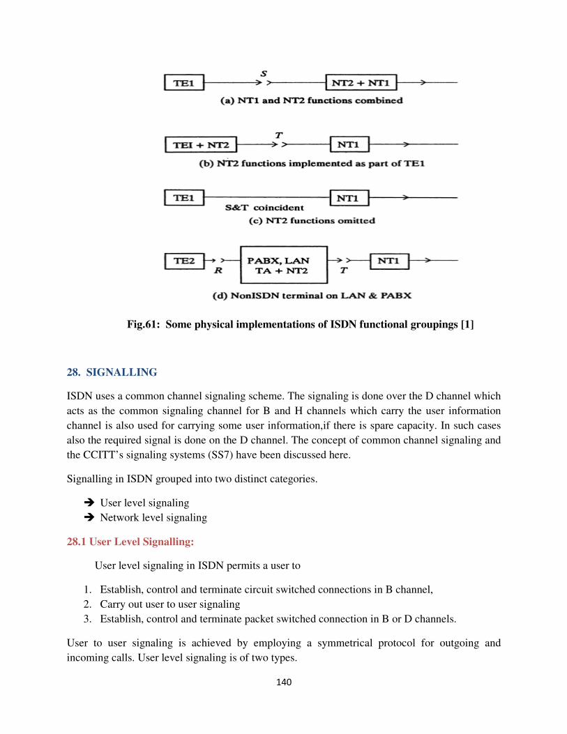
140
Fig.61: Some physical implementations of ISDN functional groupings [1]
28. SIGNALLING
ISDN uses a common channel signaling scheme. The signaling is done over the D channel which
acts as the common signaling channel for B and H channels which carry the user information
channel is also used for carrying some user information,if there is spare capacity. In such cases
also the required signal is done on the D channel. The concept of common channel signaling and
the CCITT’s signaling systems (SS7) have been discussed here.
Signalling in ISDN grouped into two distinct categories.
� User level signaling
� Network level signaling
28.1 User Level Signalling:
User level signaling in ISDN permits a user to
1. Establish, control and terminate circuit switched connections in B channel,
2. Carry out user to user signaling
3. Establish, control and terminate packet switched connection in B or D channels.
User to user signaling is achieved by employing a symmetrical protocol for outgoing and
incoming calls. User level signaling is of two types.
141
� Message based signaling
� Stimulus signaling
Message based signaling is employed when the user end equipment is an intelligent terminal. In
ISDN parlance, an intelligent terminal is known as functional terminal. It provides a user
friendly interface for signaling and performs the function of forming, sending receiving, and
replying messages. The process of establishing, controlling and terminating a call is achieved by
exchanging message between network and terminal. The message may be placed under four
groups.
1. Call establishment messages
2. Call control messages
3. Call disconnect messages
4. Miscellaneous messages
Call establishment group includes set up, call proceeding, alert, connect and connect
acknowledge messages. Alert signal corresponds to ring back signal and is used when a non
automatic answering terminal is used at the receiving end. If the auto answering facility is
available, the terminal responds with connect signal directly and the alert signal is skipped.
Call control groups include suspend and resume messages and also user to user messages.
Call disconnect groups includes disconnect, release, and release complete messages.
The primary function of miscellaneous messages is to negotiate network facilities to support
additional service features like call forwarding, direct inward dialing, reverse charging etc.
All user level messages have a common message format. These fields are mandatory for
all messages.
1. Protocol discriminator
2. Call reference
3. Message type
As the D channel may carry computer and telemetry data etc. In addition to signaling messages,
it is necessary to have a mechanism for differentiating packets and their associated protocols.
The protocol discriminator field is provided for this purpose at present two message protocols are
supported the ISDN signaling message protocol and X.25 level 3 packets protocols.
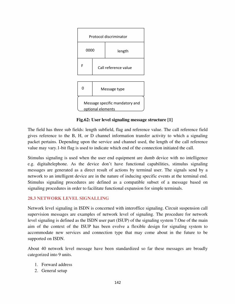
142
Fig.62: User level signaling message structure [1]
The field has three sub fields: length subfield, flag and reference value. The call reference field
gives reference to the B, H, or D channel information transfer activity to which a signaling
packet pertains. Depending upon the service and channel used, the length of the call reference
value may vary.1-bit flag is used to indicate which end of the connection initiated the call.
Stimulus signaling is used when the user end equipment are dumb device with no intelligence
e.g. digitaltelephone. As the device don’t have functional capabilities, stimulus signaling
messages are generated as a direct result of actions by terminal user. The signals send by a
network to an intelligent device are in the nature of inducing specific events at the terminal end.
Stimulus signaling procedures are defined as a compatible subset of a message based on
signaling procedures in order to facilitate functional expansion for simple terminals.
28.3 NETWORK LEVEL SIGNALLING
Network level signaling in ISDN is concerned with interoffice signaling. Circuit suspension call
supervision messages are examples of network level of signaling. The procedure for network
level signaling is defined as the ISDN user part (ISUP) of the signaling system 7.One of the main
aim of the context of the ISUP has been evolve a flexible design for signaling system to
accommodate new services and connection type that may come about in the future to be
supported on ISDN.
About 40 network level message have been standardized so far these messages are broadly
categorized into 9 units.
1. Forward address
2. General setup
Protocol discriminator
0000 length
F Call reference value
0 Message type
Message specific mandatory and
optional elements
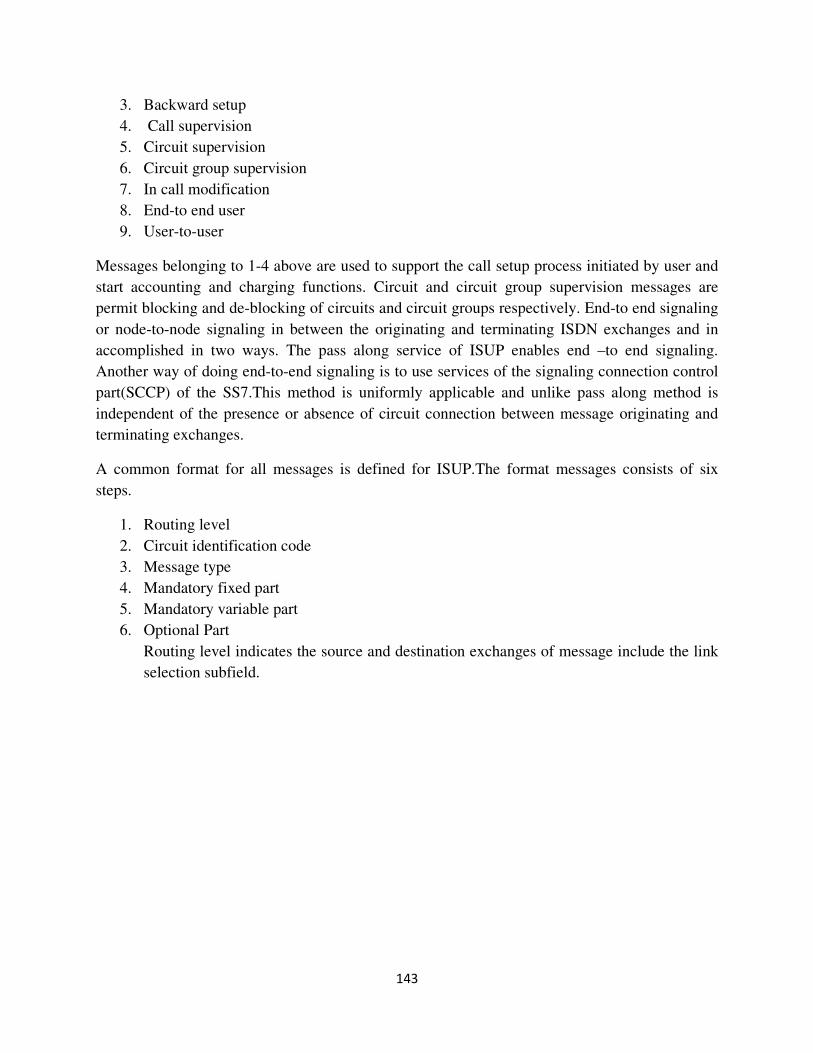
143
3. Backward setup
4. Call supervision
5. Circuit supervision
6. Circuit group supervision
7. In call modification
8. End-to end user
9. User-to-user
Messages belonging to 1-4 above are used to support the call setup process initiated by user and
start accounting and charging functions. Circuit and circuit group supervision messages are
permit blocking and de-blocking of circuits and circuit groups respectively. End-to end signaling
or node-to-node signaling in between the originating and terminating ISDN exchanges and in
accomplished in two ways. The pass along service of ISUP enables end –to end signaling.
Another way of doing end-to-end signaling is to use services of the signaling connection control
part(SCCP) of the SS7.This method is uniformly applicable and unlike pass along method is
independent of the presence or absence of circuit connection between message originating and
terminating exchanges.
A common format for all messages is defined for ISUP.The format messages consists of six
steps.
1. Routing level
2. Circuit identification code
3. Message type
4. Mandatory fixed part
5. Mandatory variable part
6. Optional Part
Routing level indicates the source and destination exchanges of message include the link
selection subfield.
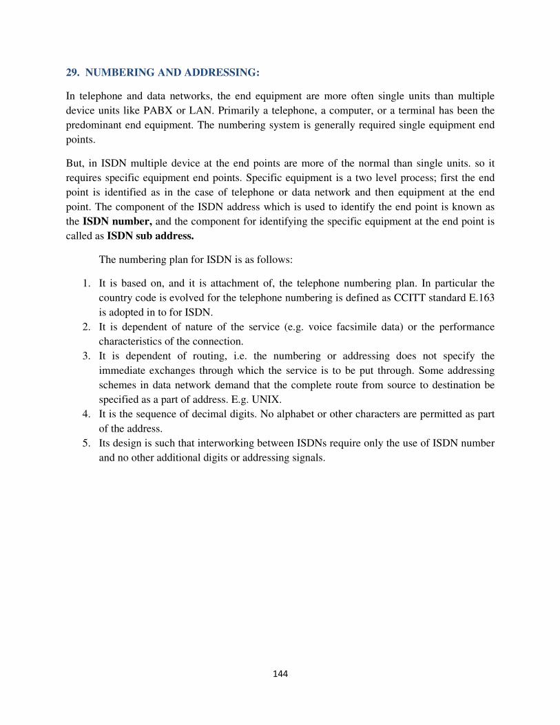
144
29. NUMBERING AND ADDRESSING:
In telephone and data networks, the end equipment are more often single units than multiple
device units like PABX or LAN. Primarily a telephone, a computer, or a terminal has been the
predominant end equipment. The numbering system is generally required single equipment end
points.
But, in ISDN multiple device at the end points are more of the normal than single units. so it
requires specific equipment end points. Specific equipment is a two level process; first the end
point is identified as in the case of telephone or data network and then equipment at the end
point. The component of the ISDN address which is used to identify the end point is known as
the ISDN number, and the component for identifying the specific equipment at the end point is
called as ISDN sub address.
The numbering plan for ISDN is as follows:
1. It is based on, and it is attachment of, the telephone numbering plan. In particular the
country code is evolved for the telephone numbering is defined as CCITT standard E.163
is adopted in to for ISDN.
2. It is dependent of nature of the service (e.g. voice facsimile data) or the performance
characteristics of the connection.
3. It is dependent of routing, i.e. the numbering or addressing does not specify the
immediate exchanges through which the service is to be put through. Some addressing
schemes in data network demand that the complete route from source to destination be
specified as a part of address. E.g. UNIX.
4. It is the sequence of decimal digits. No alphabet or other characters are permitted as part
of the address.
5. Its design is such that interworking between ISDNs require only the use of ISDN number
and no other additional digits or addressing signals.
145
Fig.63: Message format for ISDN user part [1]
29.1 Address Structure
In ISDN address the number part is maximum of 15 digits and the ISDN sub address part a
maximum of 40 digits.
National ISDN number
International ISDN no.
(Maximum 15 digits)
ISDN address
Fig.64: ISDN Address structure [1]
Country
code
National
destination code
Subscriber
Number
Subaddress
Max.
40 digits
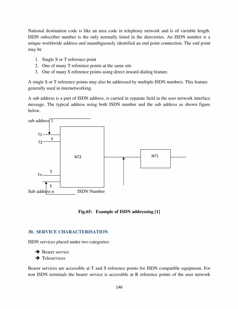
146
National destination code is like an area code in telephony network and is of variable length.
ISDN subscriber number is the only normally listed in the directories. An ISDN number is a
unique worldwide address and unambiguously identified an end point connection. The end point
may be
1. Single S or T reference point
2. One of many T reference points at the same site
3. One of many S reference points using direct inward dialing feature.
A single S or T reference points may also be addressed by multiple ISDN numbers. This feature
generally used in internetworking.
A sub address is a part of ISDN address, is carried in separate field in the user network interface
message. The typical address using both ISDN number and the sub address as shown figure
below.
sub address 1
Sub address n ISDN Number
Fig.65: Example of ISDN addressing [1]
30. SERVICE CHARACTERISATION
ISDN services placed under two categories:
� Bearer service
� Teleservices
Bearer services are accessible at T and S reference points for ISDN compatible equipment. For
non ISDN terminals the bearer service is accessible at R reference points of the user network
T1
T2
Tn
S
S
S
NT2 NT1

147
interface. A packet data transmission is an example of bearer service, whereas
telephony,teletex,videotext and facsimile are under class of teleservices.
Figure 62 shows the ISDN service possibilities.
ISDN Services
Bearer service Tele Services
Basic bearer service Basic teleservices Basic teleservice
+ Supplementary services. Basic bearer services+
Supplementary services
Fig.66: ISDN service categories [1]
Supplementary services call for additional functionalities both in lower and upper layers,
depending on whether they supplement a basic bearer service or a basic teleservice.
Bearer service or lower level service attributes are under three categories:
1. Information transfer attributes
2. Access attributes
3. General attributes
Information transfer attributes describe the network capabilities for digital information transfer
from S/T reference point of one customer to one or more S/T reference points of other
customers. The attributes used for the purpose
1. Transfer mode- circuit switched mode or packet switched mode
2. Transfer rate- one of many standard rates
3. Structure-This type of transmission implies that the integrity of data is maintained by
conveying timing information along with the data transmitted.
4. Transfer capability- It specifies the ability of network to carry structured data or
unstructured data, restricted or unrestricted data, speech,audio and so on.
Some typical examples of transfer capabilities are:
� 8KHZ structured unrestricted
� 8KHZ structured speech
� 8KHZ structured ,3.1KHZ audio
The information transfer attributes 1-4 are referred to as dominant attributes.

148
5. Establishment communication-It can take three values demand, reserved, or permanent
connection. In demand communication, a set communication is setup and released on
demand. In reserve mode setup and release time is fixed in advance by the customer. In
permanent a connection is pre-established.
6. Establishment of connection-It may take three values: switch, semi-permanent,
permanent. Semi-permanent connection is a switched connection but provided for an
indefinite period. Permanent connection is non switched connection, like a leased line
bypassing the ISDN exchange.
7. Communication configuration-The configuration of communication may be point-to-
point, multipoint or broadcast.
8. Connection configuration-The attribute connection configuration is of three sub
attributes:
� Topology
� Uniformity
� Dynamics
Topology may be simple with one connection element or tandem with two or more
connections being formed with two or more elements put in parallel. Uniformity specifies
the homogeneity of elements involved in connection. The dynamics connection deals with
temporal aspect of establishing or releasing connections.
Symmetry deals with the information flow characteristics. Information flow may be
unidirectional or bidirectional symmetric or bidirectional asymmetric. The information
transfer attributes 5-9 are referred to as secondary attributes.
The third category of bearer service attributes, i.e.general attributes including the
followings.
1. Supplementary services
2. Quality of services
3. Connection performance
4. Interworking
5. Commercial or operational attributes
A List of supplementary services in ISDN
Abbreviated dialing closed user group
Do not disturb reverse charging
Call waiting display call forwarding
Call bearing conference calls
Three party services directdialing
City wide Centrexcredit card calling
149
A number of parameters are associated with quality of services:-
Flexibility-Ability to choose different services or terminal equipment and to interwork
services
Cost/Charging-Ability to give correct billing and appropriate billing/ charging information
desired by the user.
User friendliness- Provision of prompts and voice announcements
Ergonomicity-Aesthetic and ergonomic aspects of terminal equipment
Waiting time- Waiting time for the user to obtain service or terminal equipment
Enhance ability-Progressive introduction of new facility and technology upgrades.
Reliability-Mean time between failures, mean time to repair.
Promptness- Delay in establishment /release in connection
Fidelity-quality of production
Backup assistance-User training, maintenance
Transfer speed-End to end information transfer time or through put
Universality-ability to interwork other private or public network
The attributes characterizing teleservices are also placed under three broad categories.:
1. Low layer attributes
2. High layer attributes
3. General attributes
Low layer attributes is same as the attributes for bearer services and in particular the
information transfer and the access attributes. High layer attributes deal with different
communication aspects such as voice, audio, text, facsimile and picture transmission. They
are defined in the forms of protocol confirming the OSI model.
31. INTERWORKING
ISDN interworking network based on three types of networks. i.e. the analog network, the
56kbps digital network for voice or data, and the ISDN with 64 kbps clear channel.
Interoperability is achieved through interworking function (IWF) are different for different
network and interface details.

150
IWF
IWF=Interworking Function
Fig.67: Coexistence of ISDN with other network [1]
Separate reference points have been identified and their interface details have been defined to
enable interworking with different networks.
Reference points Interworking With
K Analog or IDN (voice or data) when the IWF is implemented in ISDN
L Analog or IDN when the IWF is implemented as part of existing network
M Specialized service providers or value added networks(VANs)
N Another ISDN
P A specialized resource with ISDN
Interworking functions of ISDN with other networks having following objectives
1. Determine if the network resources of the nonISDN network are adequate to meet the
ISDN service demand.
Analog
56kbps
ISDN
64kbps
ISDN
151
2. In case the network resources are inadequate, take suitable action to cancel the call,
reroute the call or renegotiate with ISDN to be consistent with the available resources.
3. Map signaling messages two ISDN and nonISDN signaling systems.
4. Ensure service and connection compatibility, such as compatibility of call process tones,
call failure indication and signal processing modules like echo canceller.
5. Provide transmission structure conversion, including modulation technique and frame
structure conversion.
6. Provide error and flow control.
7. Collect data for billing and charging.
8. Coordinate operation and maintenance procedures to be able to isolate faults.
9. Enable interworking of the numbering schemes.
The above interworking functions point to need the parameter exchange among the existing
nonISDN terminals, ISDN terminals, and the strategically located IWF modules.
31.1 Numbering Interworking
The international PSTN numbering scheme used a 12 digit numbers with a two part format of
country code and national significant number. Other ISDN also uses 15 digit numbers.ISO
defined its own numbering scheme in the context of OSI reference model. However two basic
methods for interworking between the ISDN numbering plan and other have been proposed:
� Two-stage or port method
� Single stage or integrated numbering method.
In the port method the numbering plan of the network to which the called party is attached is
treated as calling party’s network and a two stage dialing is used.
The main disadvantages of two stage dialing are:
� The user dials two sets of numbers.
� Dialing is dependent on the relative numbering plans of the called and calling terminal.
� A delimiter or pause is necessary between two stages e.g to obtain the dial tone of
second network.
� The dialing becomes even more cumbersome if more than two networks are evolved in
establishing a connection.
An important advantage of two stage scheme that is simple to implement and is universally
acceptable.
In a single stage or integrated numbering scheme, a prefix is used to identify a particular network
and thereafter the numbering scheme of the destination network is dialed.
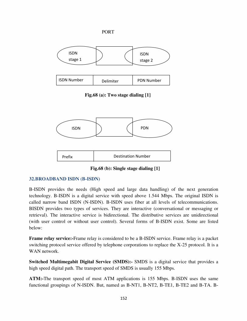
152
PORT
Fig.68 (a): Two stage dialing [1]
Fig.68 (b): Single stage dialing [1]
32.BROADBAND ISDN (B-ISDN)
B-ISDN provides the needs (High speed and large data handling) of the next generation
technology. B-ISDN is a digital service with speed above 1.544 Mbps. The original ISDN is
called narrow band ISDN (N-ISDN). B-ISDN uses fiber at all levels of telecommunications.
BISDN provides two types of services. They are interactive (conversational or messaging or
retrieval). The interactive service is bidirectional. The distributive services are unidirectional
(with user control or without user control). Several forms of B-ISDN exist. Some are listed
below:
Frame relay service:-Frame relay is considered to be a B-ISDN service. Frame relay is a packet
switching protocol service offered by telephone corporations to replace the X-25 protocol. It is a
WAN network.
Switched Multimegabit Digital Service (SMDS):- SMDS is a digital service that provides a
high speed digital path. The transport speed of SMDS is usually 155 Mbps.
ATM:-The transport speed of most ATM applications is 155 Mbps. B-ISDN uses the same
functional groupings of N-ISDN. But, named as B-NT1, B-NT2, B-TE1, B-TE2 and B-TA. B-
ISDN
stage 1
ISDN
stage 2
ISDN Number Delimiter PDN Number
ISDN PDN
Prefix Destination Number
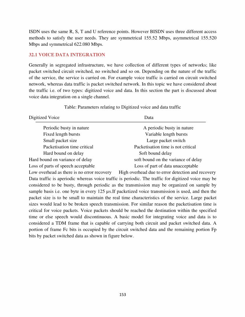
153
ISDN uses the same R, S, T and U reference points. However BISDN uses three different access
methods to satisfy the user needs. They are symmetrical 155.52 Mbps, asymmetrical 155.520
Mbps and symmetrical 622.080 Mbps.
32.1 VOICE DATA INTEGRATION
Generally in segregated infrastructure, we have collection of different types of networks; like
packet switched circuit switched, no switched and so on. Depending on the nature of the traffic
of the service, the service is carried on. For example voice traffic is carried on circuit switched
network, whereas data traffic is packet switched network. In this topic we have considered about
the traffic i.e. of two types: digitized voice and data. In this section the part is discussed about
voice data integration on a single channel.
Table: Parameters relating to Digitized voice and data traffic
Digitized Voice Data
Periodic busty in nature A periodic busty in nature
Fixed length bursts Variable length bursts
Small packet size Large packet switch
Packetisation time critical Packetisation time is not critical
Hard bound on delay Soft bound delay
Hard bound on variance of delay soft bound on the variance of delay
Loss of parts of speech acceptable Loss of part of data unacceptable
Low overhead as there is no error recovery High overhead due to error detection and recovery
Data traffic is aperiodic whereas voice traffic is periodic. The traffic for digitized voice may be
considered to be busty, through periodic as the transmission may be organized on sample by
sample basis i.e. one byte in every 125 µs.If packetized voice transmission is used, and then the
packet size is to be small to maintain the real time characteristics of the service. Large packet
sizes would lead to be broken speech transmission. For similar reason the packetisation time is
critical for voice packets. Voice packets should be reached the destination within the specified
time or else speech would discontinuous. A basic model for integrating voice and data is to
considered a TDM frame that is capable of carrying both circuit and packet switched data. A
portion of frame Fc bits is occupied by the circuit switched data and the remaining portion Fp
bits by packet switched data as shown in figure below.

154
Frame = F bits
Fig.69: An integrated TDM network [1]
Circuit switched traffic= Fc bits
Packet switched traffic= Fp bits
Fc+ Fp=F
A number of circuit switched sources may constitute the Fc bits of the frame. Each source may
require different bandwidth and have different arrival time and holding time characteristics. A
TDM frame may considered containing N slots of b bits each, as a group of b bits likely to be
integral in any traffic.e.g. Voice samples of 8bits or a byte in data.
F=Nb slot ,One slot may be considered as a basic bandwidth unit(BBU) .A source is assigned
one or more BBU’s depending upon the bandwidth requirements. A circuit switched source is
blocked if adequate no. of BBUs are not available for the assignment and a packet switched
source is queued awaiting free BBUs. For voice data integration we restrict the circuit switched
traffic to voice. i.e. all sources have equal bandwidth requirement of one BBU and the same
arrival time and the holding time characteristics. Similarly all packet switched sources may be
considered to have the same arrival and service time characteristics for simplicity.
Voice data Integration schemes followed by may be placed under two characteristics:
� Random allocation of BBUs
� Contiguous allocation of BBUs
In random allocation, any available BBU is allocated to either voice or data using some criterion.
The usual criteria include First-come-first-serve basis (FCFS) and pre-emptive scheduling. In
contiguous allocation schemes attempts are made to gather together all BBUs allotted to voice
and so also BBUs allotted to data traffic. The contiguous allocation schemes can be classified as:
� Fixed boundary scheme
� Movable boundary scheme
In Fixed boundary scheme, the N slots in the frame are divided into two parts containing N1 &
N2 =N-N1, slots respectively as shown figure 65(a).
1 2 3 . . . . . . . N 2 N 1 N
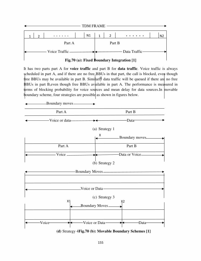
155
TDM FRAME
Part A Part B
Voice Traffic Data Traffic
Fig.70 (a): Fixed Boundary Integration [1]
It has two parts part A for voice traffic and part B for data traffic. Voice traffic is always
scheduled in part A, and if there are no free BBUs in that part, the call is blocked, even though
free BBUs may be available in part B. Similarly data traffic will be queued if there are no free
BBUs in part B,even though free BBUs available in part A. The performance is measured in
terms of blocking probability for voice sources and mean delay for data sources.In movable
boundary scheme, four strategies are possible as shown in figures below.
Boundary moves
Part A Part B
Voice or data Data
(a) Strategy 1
Boundary moves
Part A Part B
Voice Data or Voice
(b) Strategy 2
Boundary Moves
Voice or Data
(c) Strategy 3
Boundary Moves
Voice Voice or Data Data
(d) Strategy 4Fig.70 (b): Movable Boundary Schemes [1]
1 2
. . . . . . N1 1 2 N2 . . . . . .
X
X
X1 X2
156
In strategy 1 and 2, there is a national boundary shown at X. In the former data traffic is allowed
to use free BBUs. If a voice source arrives, then a data source occupying the voice area is pre-
empted and the BBUs are allotted to the voice source .In this sense the boundary moves back and
forth to the left of X. If all the BBUs in part A occupied by voice sources ,further voice arrivals
are blocked even if free BBUs are available in part B. This strategy gives the same blocking
probability performance as the fixed boundary scheme for voice sources;but it provides better
delay performance for data sources.
In strategy 2, the boundary is allowed to move according to figure shown above, thereby
providing additional bandwidth to voice sources when available. Consequently if the voice
sources hold up BBUs in the data traffic for a long time, the delay performance for the data
traffic may be affected adversely.
In strategy 3, the boundary shifts dynamically throughout the frame, depending on the traffic
load. Pre-empting may be permitted in this strategy for voice traffic. In strategy voice may be
completed domination the channel, hence forth some researchers referred to strategy 4 as shown
in figure, where a minimum bandwidth allocation is always assured for both voice or data traffic.
Such traffic is also known as min-max scheduling as there is a minimum and maximum
bandwidth bound for either of traffic.
157
References:
1. Telecommunication Switching Systems and Networks byThiagarjanViswanathan PHI
Publication, NEW DELHI
2. http://www.daenotes.com/electronics/communication-system/satellite-communication
3. (http://www.dropwire.co.uk/)
4. http://www.ies.org/tutorials/fund-telecom/
5. http://telecom.jnag.com/
6. http://www.telephonyworld.com/
7.
158
LECTURE NOTES ON “DIGITAL SWITCHING AND
TELECOM NETWORK”
Semester: 7th semester, B.Tech
Branch: Electronics & Telecommunication Engineering
Subject code: PEEC5404
PREPARED BY:
1) Dr. Urmila Bhanja
Associate Professor
2)Monalisa Nayak
Assistant Professor
3) Paresh Kumar Pasayat
Assistant Professor
Department of Electronics & Telecommunication Engineering.
INDIRA GANDHI INSTITUTE OF TECHNOLOGY
SARANG
ODISHA
759146


![Introduction to telecommunication systems - Pure · -switching systems ... networks or into the upper levels (trunk network). ... Introduction to Telecommunication Systems ]99]](https://img.pdfslide.us/doc/110x75/5ad67e927f8b9a177c8e5e92/introduction-to-telecommunication-systems-pure-systems-networks-or-into-the.jpg)