Embed Size (px)
Citation preview
Profile rail guides - LLR catalogue

1
Contents
1 Introduction ....................................................................41.1 Product description ........................................................51.2 Design ............................................................................61.2.1 Components and material specifications ................7
1.3 Features and benefits ....................................................81.4 Product range .................................................................9
2 Selection guide .............................................................102.1 Technical data .............................................................. 11
2.1.1 General information ............................................... 112.1.2 Load rating .............................................................. 122.1.3 Preload classes ...................................................... 132.1.4 Accuracy .................................................................. 152.1.5 Selection criteria for combination of accuracy classes .............................................................................. 16
2.2 Calculation of bearing loads ....................................... 17
3 Product range ................................................................183.1 Carriage data ................................................................ 19
3.1.1 Carriage LLRHC ... SA ...........................................223.1.2 Carriage LLRHC ... A ..............................................243.1.3 Carriage LLRHC ... LA ............................................263.1.4 Carriage LLRHC ... SU ...........................................283.1.5 Carriage LLRHC ... U ..............................................303.1.6 Carriage LLRHC ... LU ............................................323.1.7 Carriage LLRHC ... R ..............................................343.1.8 Carriage LLRHC ... LR ............................................36
3.2 Rail data .......................................................................393.2.1 LLRHR rails ............................................................403.2.2 LLRHR D2 rails ......................................................42
3.3 Accessories ..................................................................453.3.1 Scraper plate ..........................................................463.3.2 Two-piece front seal .............................................. 473.3.3 Seal kit ...................................................................483.3.4 Bellows ...................................................................493.3.5 Lubrication adapter ...............................................503.3.6 Cover strip ............................................................. 513.3.7 Expanding mandrel to create a slide on the cover strip ..................................................................................523.3.8 Cover strip retaining clamps .................................53
4 Mounting instruction and maintenance .....................544.1 Design rules ..................................................................55
4.1.1 General instructions ................................................554.1.2 Assembly examples ................................................554.1.3 Stop edges, corner radii, screw sizes and tightening torques ..............................................................................564.1.4 Pinning .....................................................................584.1.5 Loading of the screw connections between rail and substructure .....................................................................604.1.6 Height deviation ......................................................614.1.7 Parallelism of mounted rails measured on the rails and the carriages ..............................................................624.1.8 Mounting of lubrication adapter ..............................634.1.9 Mounting bellow ......................................................64
4.2 Maintenance and repairs .............................................654.3 Ordering key .................................................................68

Armada
Toronto
Philadelphia
TurinLiestal
Steyr
Sofia
BudapestMeckesheim
Sales Unit
Manufacturing Unit
Countries supported by Sales Unit
UtrechtMilton Keynes
Gothenburg
Schweinfurt
ChambéryGuyancourt
Pinghu
ShanghaiSeoul
Bangalore
Taouyan
Technology leadership Our journey began over 50 years ago as part of the SKF Group, and our history with SKF provided us with the exper-tise to continuously develop new technologies and use them to create cutting edge products that offer our custom-ers a competitive advantage.
In 2019, we became independent from SKF and changed our name to Ewellix. We are proud of our heritage. This gives us a unique foundation on which to build an agile busi-ness with engineering excellence and innovation as our core strengths.
Global presence and local supportWith our global presence, we are uniquely positioned to deliver standard components and custom-engineered solutions, with full technical and applications support around the world. Long standing relationships with our dis-tributor partners allow us to support customers in a variety of different industries. At Ewellix, we don’t just provide prod-ucts; we engineer integrated solutions that help custom-ers realise their ambitions.
Heritage of innovation for technology leadership
Ewellix is a global innovator and manufacturer of linear motion and actuation solutions.Today, our state-of-the-art linear solutions are designed to increase machine performance, maximise uptime, reduce maintenance, improve safety and save energy.
1 200 employees
16 sales units
9 factories

3
Actuation systems Ball and roller screws Linear guides and systems
Trusted engineering expertise
Engineering for the futureWe work in a wide range of industries, where our solutions provide key functionality for business critical applications.For the medical industry, we provide precision components for use in core medical equipment. Our unparalleled understanding of industrial automation systems is based on decades of research into advanced automation components and techniques.Our deep knowledge of mobile machinery provides powerful and reliable electromechanical solutions for the harshest conditions. In an industrial distribution setting, we supply linear expertise to our partners, empowering them to serve customers with greater efficiency.
We offer excellenceWe have a unique understanding of linear equipment and how it’s integrated in customers’ applications to provide the best performance and machine efficiency.We assist our customers by creating equipment that runs faster, longer and safer and that is sustainable. We provide a wide variety of linear motion components and electromechanical actuators for equipping any automation application, helping our customers reduce its footprint, energy use and maintenance.We push for lower energy consumption that increases productivity and reduces the environmental impact.
Our industry is in motion; pushing towards solutions that reduce environmental impact and leverage new technology. We provide technical and manufacturing expertise to overcome our customers’ challenges.

Introduction
1
5
Introduction
11.1 Product description
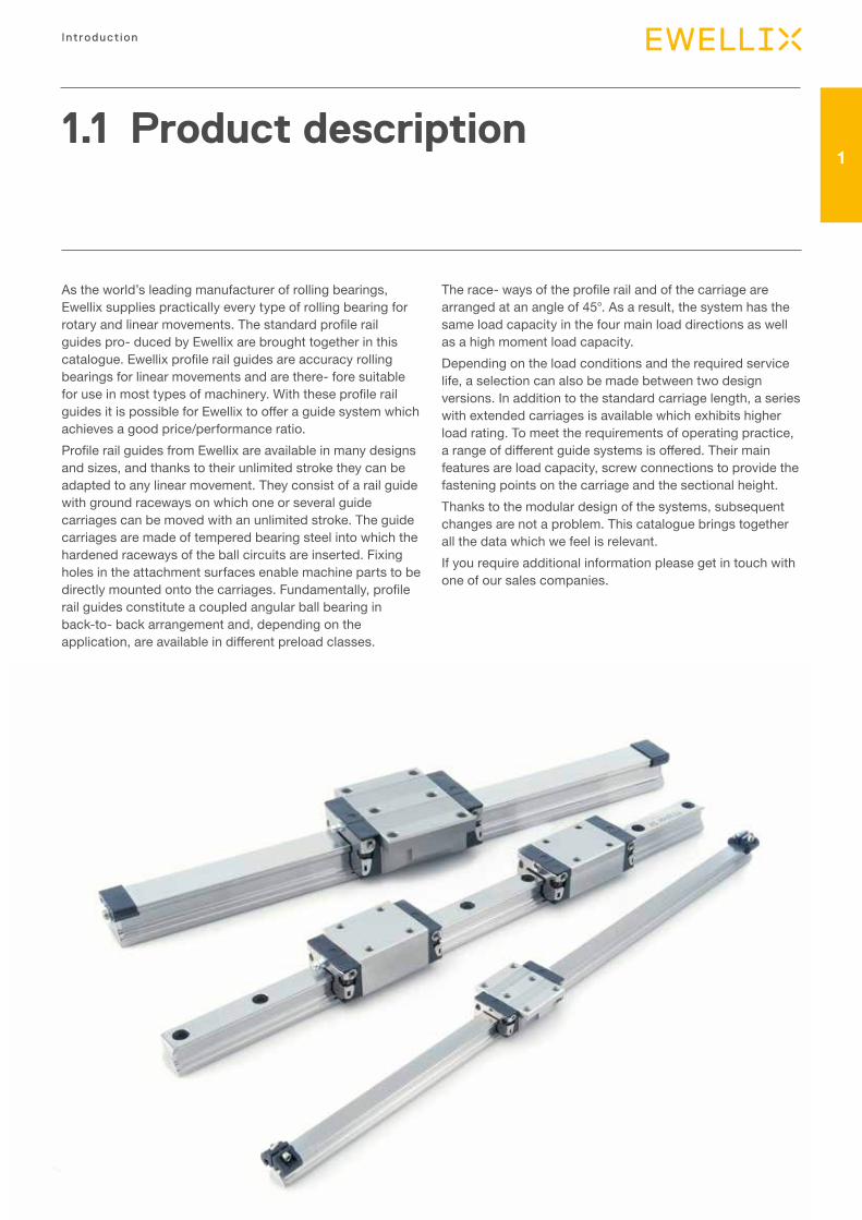
As the world’s leading manufacturer of rolling bearings, Ewellix supplies practically every type of rolling bearing for rotary and linear movements. The standard profile rail guides pro- duced by Ewellix are brought together in this catalogue. Ewellix profile rail guides are accuracy rolling bearings for linear movements and are there- fore suitable for use in most types of machinery. With these profile rail guides it is possible for Ewellix to offer a guide system which achieves a good price/performance ratio.Profile rail guides from Ewellix are available in many designs and sizes, and thanks to their unlimited stroke they can be adapted to any linear movement. They consist of a rail guide with ground raceways on which one or several guide carriages can be moved with an unlimited stroke. The guide carriages are made of tempered bearing steel into which the hardened raceways of the ball circuits are inserted. Fixing holes in the attachment surfaces enable machine parts to be directly mounted onto the carriages. Fundamentally, profile rail guides constitute a coupled angular ball bearing in back-to- back arrangement and, depending on the application, are available in different preload classes.
The race- ways of the profile rail and of the carriage are arranged at an angle of 45°. As a result, the system has the same load capacity in the four main load directions as well as a high moment load capacity.Depending on the load conditions and the required service life, a selection can also be made between two design versions. In addition to the standard carriage length, a series with extended carriages is available which exhibits higher load rating. To meet the requirements of operating practice, a range of different guide systems is offered. Their main features are load capacity, screw connections to provide the fastening points on the carriage and the sectional height.Thanks to the modular design of the systems, subsequent changes are not a problem. This catalogue brings together all the data which we feel is relevant.If you require additional information please get in touch with one of our sales companies.
6
Prof i le ra i l gu ides - LLR
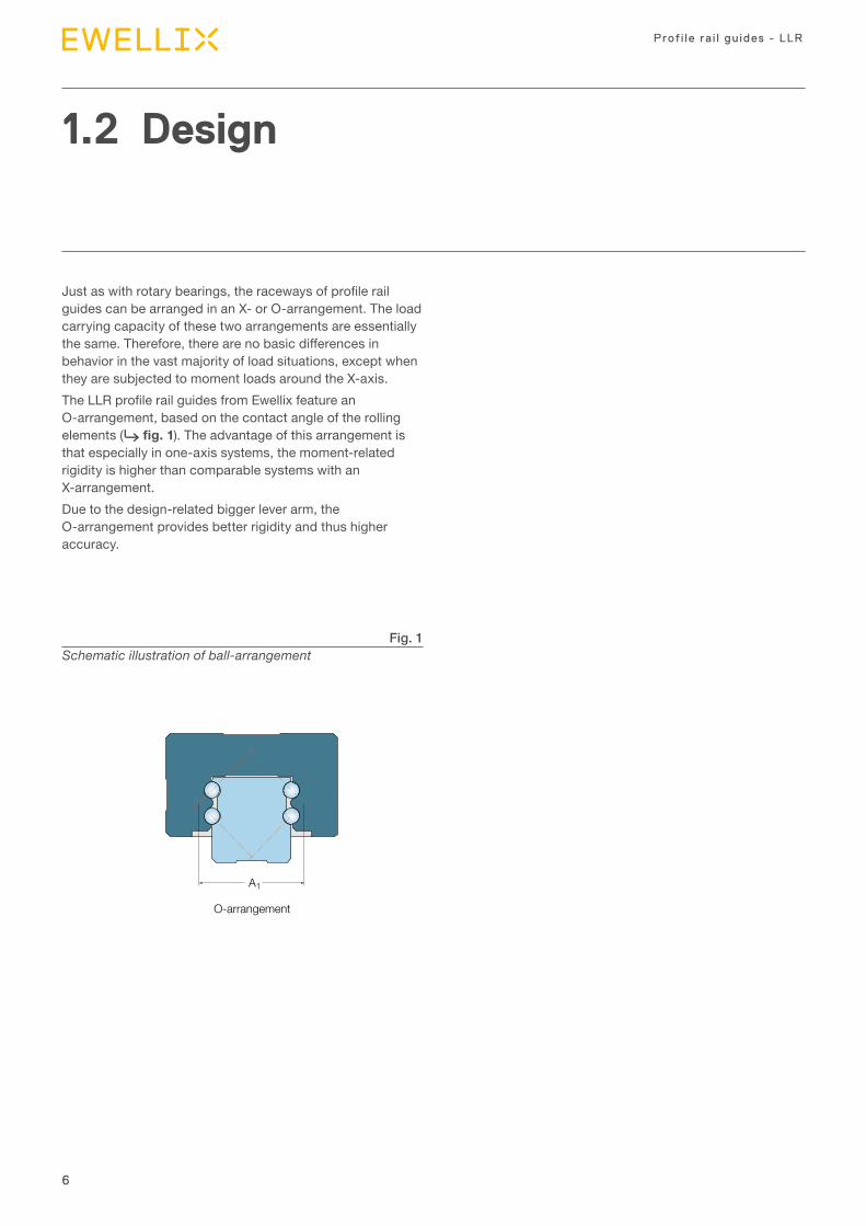
Just as with rotary bearings, the raceways of profile rail guides can be arranged in an X- or O-arrangement. The load carrying capacity of these two arrangements are essentially the same. Therefore, there are no basic differences in behavior in the vast majority of load situations, except when they are subjected to moment loads around the X-axis.The LLR profile rail guides from Ewellix feature an O-arrangement, based on the contact angle of the rolling elements (⮑ fig. 1). The advantage of this arrangement is that especially in one-axis systems, the moment-related rigidity is higher than comparable systems with an X-arrangement.Due to the design-related bigger lever arm, the O-arrangement provides better rigidity and thus higher accuracy.
1.2 Design
A1
O-arrangement
Fig. 1Schematic illustration of ball-arrangement
7
Introduction
1
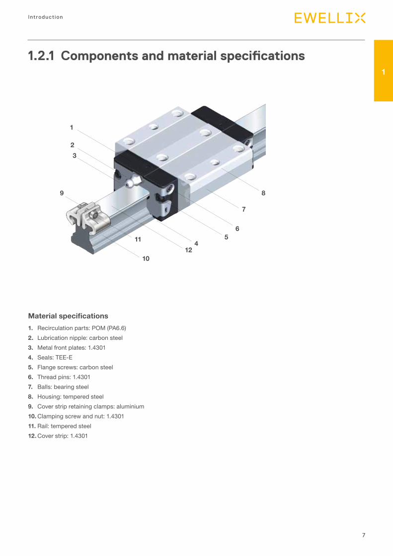
1.2.1 Components and material specifications
1
2
3
9
11
1012
45
6
7
8
1
23
9
10
1112
45
6
7
8
Material specifications1. Recirculation parts: POM (PA6.6)2. Lubrication nipple: carbon steel3. Metal front plates: 1.43014. Seals: TEE-E5. Flange screws: carbon steel6. Thread pins: 1.43017. Balls: bearing steel8. Housing: tempered steel9. Cover strip retaining clamps: aluminium10. Clamping screw and nut: 1.430111. Rail: tempered steel12. Cover strip: 1.4301
8
Prof i le ra i l gu ides - LLR
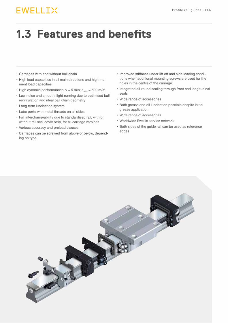
• Carriages with and without ball chain• High load capacities in all main directions and high mo-
ment load capacities• High dynamic performances: v = 5 m/s; amax = 500 m/s2
• Low noise and smooth, light running due to optimised ball recirculation and ideal ball chain geometry
• Long term lubrication system• Lube ports with metal threads on all sides.• Full interchangeability due to standardised rail, with or
without rail seal cover strip, for all carriage versions• Various accuracy and preload classes• Carriages can be screwed from above or below, depend-
ing on type.
1.3 Features and benefits
• Improved stiffness under lift off and side loading condi-tions when additional mounting screws are used for the holes in the centre of the carriage
• Integrated all-round sealing through front and longitudinal seals
• Wide range of accessories• Both grease and oil lubrication possible despite initial
grease application• Wide range of accessories• Worldwide Ewellix service network• Both sides of the guide rail can be used as reference
edges
9
Introduction
11.4 Product range
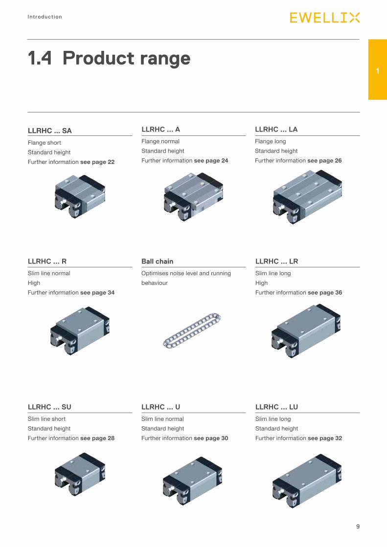
LLRHC ... SAFlange short Standard heightFurther information see page 22
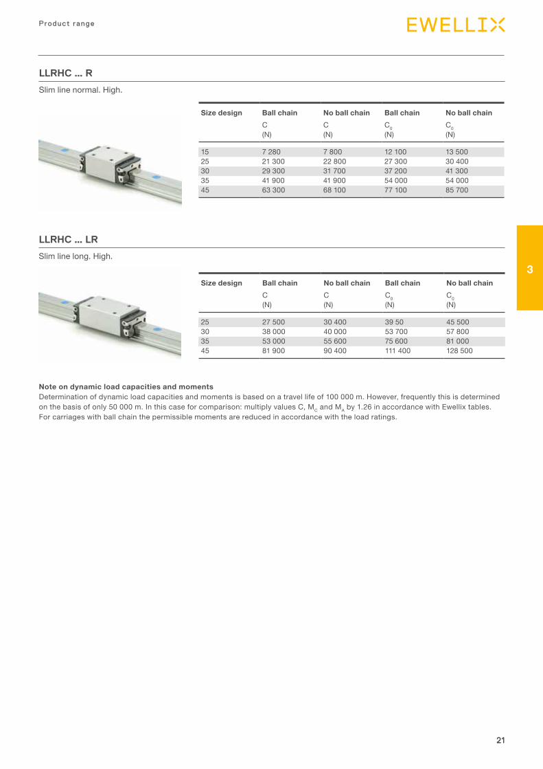
LLRHC ... R
Slim line normalHighFurther information see page 34
LLRHC ... SU
Slim line shortStandard heightFurther information see page 28
Ball chain
Optimises noise level and runningbehaviour
LLRHC ... U
Slim line normalStandard height Further information see page 30
LLRHC ... LR
Slim line longHighFurther information see page 36
LLRHC ... LU
Slim line longStandard heightFurther information see page 32
LLRHC ... A
Flange normal Standard heightFurther information see page 24
LLRHC ... LA
Flange long Standard heightFurther information see page 26
5
LLRHC xx SAFlange short. Standard height.
LLRHC xx AFlange normal. Standard height.
LLRHC xx LAFlange long. Standard height.
LLRHC xx RSlim line normal. High.
Ball chainOptimises noise level and runningbehaviour
LLRHC xx LRSlim line long. High.
LLRHC xx SUSlim line short. Standard height.
LLRHC xx LUSlim line long. Standard height.
LLRHC xx USlim line normal. Standard height.

2 Selection guide

11
2
11
Selection gu ide
2.1 Technical data
2.1.1 General information The general technical data applies to all rail guides (all carriages and rails). Special technical data is listed separately for the individual designs.
Preload classesIn view of the different user require- ments, the ball rail guides can be supplied in four different preload classes.So as not to reduce the service life, the preload should not amount to more than 1/3 of the bearing load F.In general, the stiffness of the carriage increases according to the preload increase.
Guide systems with parallel rails
• In connection with the selected preload class the permissi-ble deviation in parallelism of the rails must also be taken into account (see tables for the various designs).
• For the installation of rail guides in the accuracy class P5 we recommend the version with clearance T0 or the preload class T1 in order to avoid stresses owing to the tolerances.
Speed vmax: 5 m/s
Accelerationamax: 500 m/s2
Only in the case of preloaded systems. In the case of non-preloaded systems: amax = 50 m/s2
Temperature resistancetmax: 100 °CThis is a maximum value which is only permissible for a short time. In continuous operation a maximum temperature of 80 °C must not be exceeded.
12
Prof i le ra i l gu ides - LLR
12
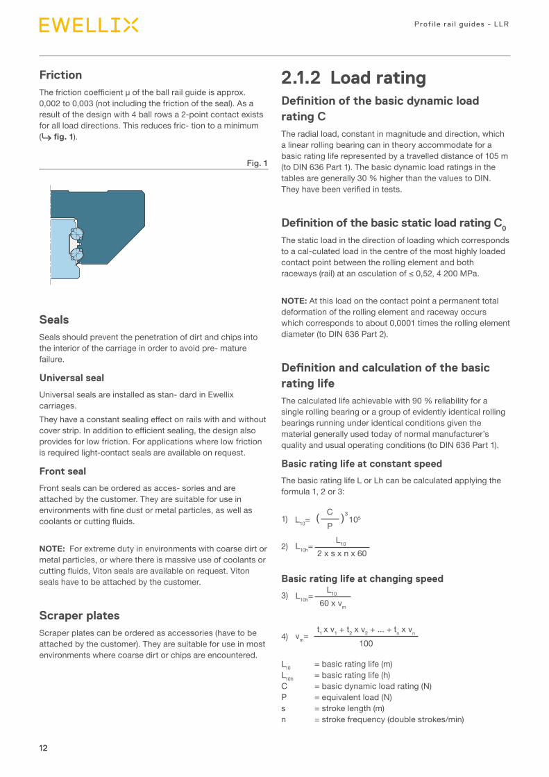
FrictionThe friction coefficient µ of the ball rail guide is approx. 0,002 to 0,003 (not including the friction of the seal). As a result of the design with 4 ball rows a 2-point contact exists for all load directions. This reduces fric- tion to a minimum (⮑ fig. 1).
Fig. 1
SealsSeals should prevent the penetration of dirt and chips into the interior of the carriage in order to avoid pre- mature failure.
Universal seal
Universal seals are installed as stan- dard in Ewellix carriages.They have a constant sealing effect on rails with and without cover strip. In addition to efficient sealing, the design also provides for low friction. For applications where low friction is required light-contact seals are available on request.
Front seal
Front seals can be ordered as acces- sories and are attached by the customer. They are suitable for use in environments with fine dust or metal particles, as well as coolants or cutting fluids.
NOTE: For extreme duty in environments with coarse dirt or metal particles, or where there is massive use of coolants or cutting fluids, Viton seals are available on request. Viton seals have to be attached by the customer.
Scraper platesScraper plates can be ordered as accessories (have to be attached by the customer). They are suitable for use in most environments where coarse dirt or chips are encountered.
2.1.2 Load ratingDefinition of the basic dynamic load rating CThe radial load, constant in magnitude and direction, which a linear rolling bearing can in theory accommodate for a basic rating life represented by a travelled distance of 105 m (to DIN 636 Part 1). The basic dynamic load ratings in the tables are generally 30 % higher than the values to DIN. They have been verified in tests.
Definition of the basic static load rating C0
The static load in the direction of loading which corresponds to a cal-culated load in the centre of the most highly loaded contact point between the rolling element and both raceways (rail) at an osculation of ≤ 0,52, 4 200 MPa.
NOTE: At this load on the contact point a permanent total deformation of the rolling element and raceway occurs which corresponds to about 0,0001 times the rolling element diameter (to DIN 636 Part 2).
Definition and calculation of the basic rating lifeThe calculated life achievable with 90 % reliability for a single rolling bearing or a group of evidently identical rolling bearings running under identical conditions given the material generally used today of normal manufacturer’s quality and usual operating conditions (to DIN 636 Part 1).
Basic rating life at constant speed
The basic rating life L or Lh can be calculated applying the formula 1, 2 or 3:
1) 3
L10= 105
C( )P
2) L10 2 x s x n x 60
L10h=
Basic rating life at changing speed
3)
L10h=L10
60 x vm
4) vm= t1 x v1 + t2 x v2 + ... + tn x vn
100
L10 = basic rating life (m) L10h = basic rating life (h) C = basic dynamic load rating (N) P = equivalent load (N) s = stroke length (m) n = stroke frequency (double strokes/min)
13
2
13
Selection gu ide
vm = mean speed (m/min) v1,v2...vn = travel speeds (m/min) t1,t2...tn = time proportions for v1, v2...vn (%)
The formulae for calculating the service life of profile rail guides apply to a stroke length of S ≥ 2 times the carriage length. At lower values the load rating is reduced. Please consult Ewellix.
Dynamic equivalent bearing load for calculation of the service lifeFor a fluctuating bearing load the dynamic equivalent loading F is calculated according to formula 5:
5) Fm= 3
F13 x s1 + F2
3 x s2 + ... + Fn3 x sn
s
Fm = constant mean load (N)F1, F2 ... Fn = constant loads during stroke lengths s1,
+ s2 +, ...sn (N)s = total stroke length (s = s1 + s2 +, ...+ sn),
during which loads F1, F2 ... Fn have an effect (mm)
* given a combined bearing load
Note on dynamic load capacities and momentsDetermination of dynamic load capacities and moments is based on a travel life of 100 000 m. However, frequently this is determined on the basis of only 50 000 m. In this case for comparison: multiply values C, MC and MA by 1.26 in accordance with Ewellix tables. For carriages with ball chain the permissible moments are reduced in accordance with the load ratings.
Preload class Preload force FPr
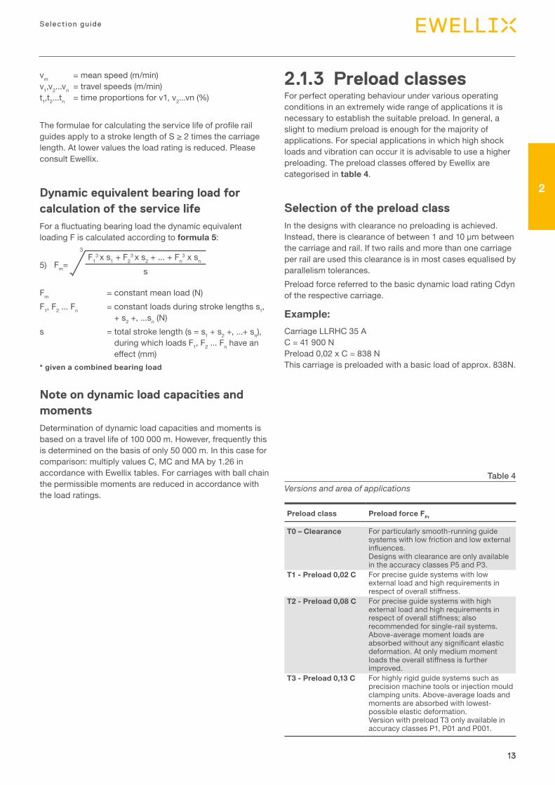
T0 – Clearance For particularly smooth-running guide systems with low friction and low external influences. Designs with clearance are only available in the accuracy classes P5 and P3.
T1 - Preload 0,02 C For precise guide systems with low external load and high requirements in respect of overall stiffness.
T2 - Preload 0,08 C For precise guide systems with high external load and high requirements in respect of overall stiffness; also recommended for single-rail systems. Above-average moment loads are absorbed without any significant elastic deformation. At only medium moment loads the overall stiffness is further improved.
T3 - Preload 0,13 C For highly rigid guide systems such as precision machine tools or injection mould clamping units. Above-average loads and moments are absorbed with lowest-possible elastic deformation.Version with preload T3 only available in accuracy classes P1, P01 and P001.
Table 4Versions and area of applications
2.1.3 Preload classes For perfect operating behaviour under various operating conditions in an extremely wide range of applications it is necessary to establish the suitable preload. In general, a slight to medium preload is enough for the majority of applications. For special applications in which high shock loads and vibration can occur it is advisable to use a higher preloading. The preload classes offered by Ewellix are categorised in table 4.
Selection of the preload classIn the designs with clearance no preloading is achieved. Instead, there is clearance of between 1 and 10 μm between the carriage and rail. If two rails and more than one carriage per rail are used this clearance is in most cases equalised by parallelism tolerances.Preload force referred to the basic dynamic load rating Cdyn of the respective carriage.
Example:Carriage LLRHC 35 A C = 41 900 N Preload 0,02 x C = 838 N This carriage is preloaded with a basic load of approx. 838N.
14
Prof i le ra i l gu ides - LLR
14
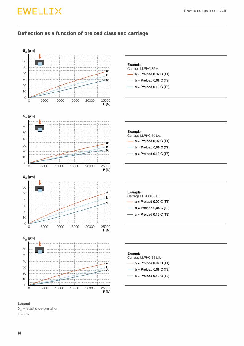
Deflection as a function of preload class and carriage
Legendδel. = elastic deformationF = load
a = Preload 0,02 C (T1)
b = Preload 0,08 C (T2)
c = Preload 0,13 C (T3)
Example:Carriage LLRHC 35 A,
a = Preload 0,02 C (T1)
b = Preload 0,08 C (T2)
c = Preload 0,13 C (T3)
Example:Carriage LLRHC 35 LA,
a = Preload 0,02 C (T1)
b = Preload 0,08 C (T2)
c = Preload 0,13 C (T3)
Example:Carriage LLRHC 35 U,
a = Preload 0,02 C (T1)
b = Preload 0,08 C (T2)
c = Preload 0,13 C (T3)
Example:Carriage LLRHC 35 LU,
60
50
40
30
2010
00 5000 10000 15000 20000 25000
F [N]
δel. [µm]
abc
60
50
40
30
2010
00 5000 10000 15000 20000 25000
F [N]
δel. [µm]
abc
60
50
40
30
2010
00 5000 10000 15000 20000 25000
F [N]
δel. [µm]
abc
60
50
40
30
2010
00 5000 10000 15000 20000 25000
F [N]
δel. [µm]
abc
15
2
15
Selection gu ide
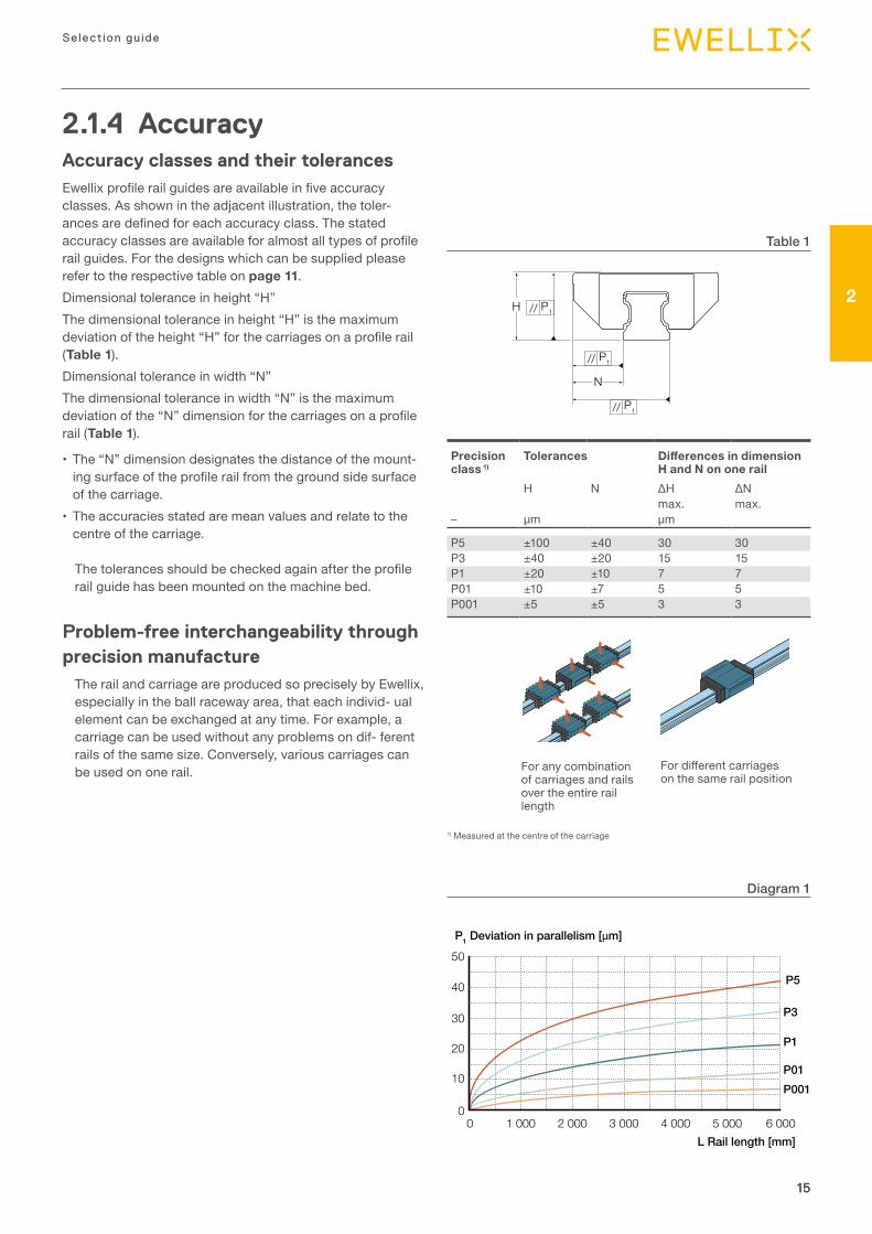
2.1.4 AccuracyAccuracy classes and their tolerancesEwellix profile rail guides are available in five accuracy classes. As shown in the adjacent illustration, the toler- ances are defined for each accuracy class. The stated accuracy classes are available for almost all types of profile rail guides. For the designs which can be supplied please refer to the respective table on page 11.Dimensional tolerance in height “H” The dimensional tolerance in height “H” is the maximum deviation of the height “H” for the carriages on a profile rail (Table 1).Dimensional tolerance in width “N” The dimensional tolerance in width “N” is the maximum deviation of the “N” dimension for the carriages on a profile rail (Table 1).
• The “N” dimension designates the distance of the mount-ing surface of the profile rail from the ground side surface of the carriage.
• The accuracies stated are mean values and relate to the centre of the carriage.
The tolerances should be checked again after the profile rail guide has been mounted on the machine bed.
Problem-free interchangeability through precision manufacture
The rail and carriage are produced so precisely by Ewellix, especially in the ball raceway area, that each individ- ual element can be exchanged at any time. For example, a carriage can be used without any problems on dif- ferent rails of the same size. Conversely, various carriages can be used on one rail.
H P1//
P1
N
//
P1//
For any combination of carriages and rails over the entire rail length
For different carriages on the same rail position
Table 1
Diagram 1
1) Measured at the centre of the carriage
P1 Deviation in parallelism [µm]
L Rail length [mm]
10
30
50
40
20
00
1 000 2 000 3 000 4 000 5 000 6 000
P5
P3
P1
P01P001
Precision class 1)
Tolerances Differences in dimension H and N on one rail
H N ∆H ∆Nmax. max.
– µm µm
P5 ±100 ±40 30 30P3 ±40 ±20 15 15P1 ±20 ±10 7 7P01 ±10 ±7 5 5P001 ±5 ±5 3 3
16
Prof i le ra i l gu ides - LLR
16
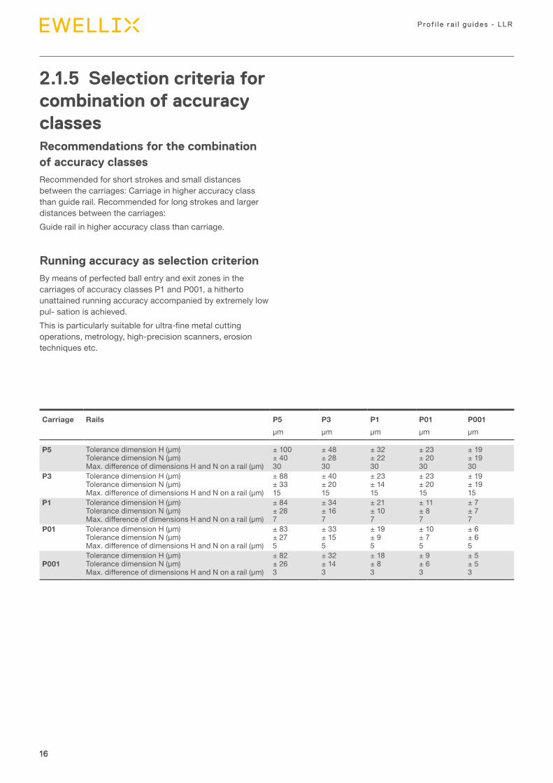
2.1.5 Selection criteria for combination of accuracy classesRecommendations for the combination of accuracy classesRecommended for short strokes and small distances between the carriages: Carriage in higher accuracy class than guide rail. Recommended for long strokes and larger distances between the carriages:Guide rail in higher accuracy class than carriage.
Running accuracy as selection criterionBy means of perfected ball entry and exit zones in the carriages of accuracy classes P1 and P001, a hitherto unattained running accuracy accompanied by extremely low pul- sation is achieved.This is particularly suitable for ultra-fine metal cutting operations, metrology, high-precision scanners, erosion techniques etc.
Carriage Rails P5 P3 P1 P01 P001μm μm μm μm μm
P5 Tolerance dimension H (μm)Tolerance dimension N (μm)Max. difference of dimensions H and N on a rail (μm)
± 100± 4030
± 48± 2830
± 32± 2230
± 23± 2030
± 19± 1930
P3 Tolerance dimension H (μm)Tolerance dimension N (μm)Max. difference of dimensions H and N on a rail (μm)
± 88± 3315
± 40± 2015
± 23± 1415
± 23± 2015
± 19± 1915
P1 Tolerance dimension H (μm)Tolerance dimension N (μm)Max. difference of dimensions H and N on a rail (μm)
± 84± 287
± 34± 167
± 21± 107
± 11± 87
± 7± 77
P01 Tolerance dimension H (μm)Tolerance dimension N (μm)Max. difference of dimensions H and N on a rail (μm)
± 83± 275
± 33± 155
± 19± 95
± 10± 75
± 6± 65
P001Tolerance dimension H (μm)Tolerance dimension N (μm)Max. difference of dimensions H and N on a rail (μm)
± 82± 263
± 32± 143
± 18± 83
± 9± 63
± 5± 53
17
2
17
Selection gu ide
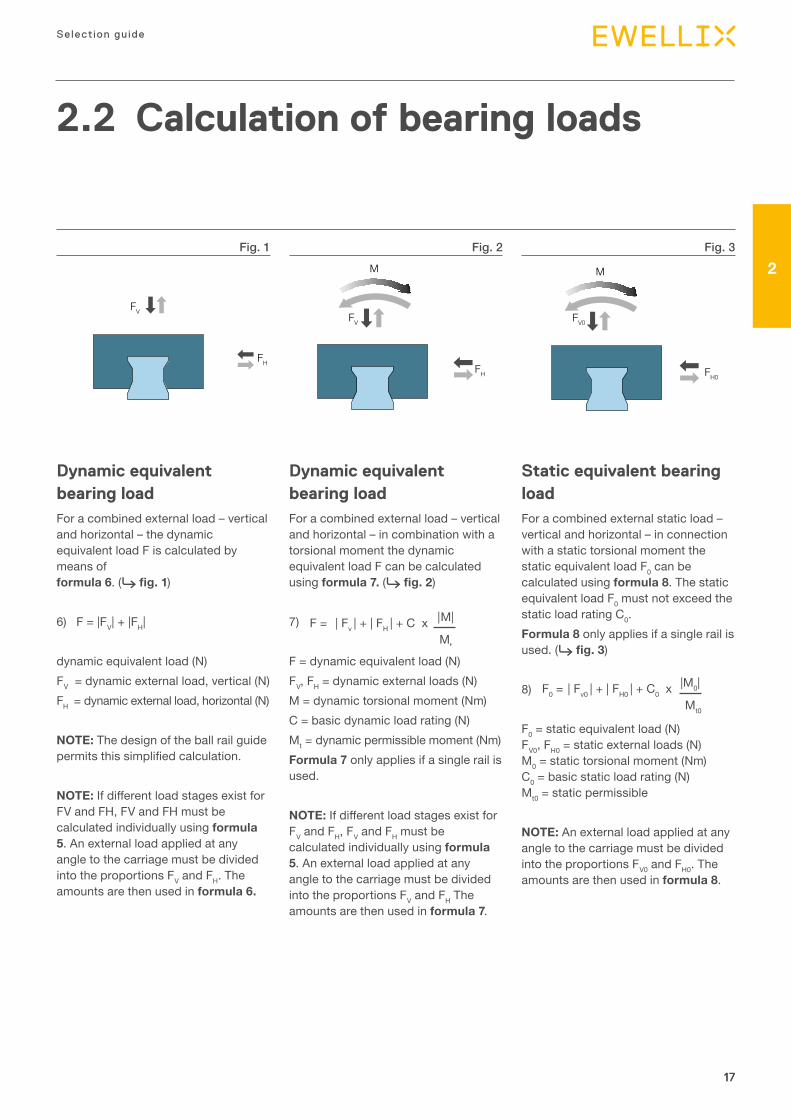
2.2 Calculation of bearing loads
Dynamic equivalent bearing load For a combined external load – vertical and horizontal – the dynamic equivalent load F is calculated by means of formula 6. (⮑ fig. 1)
6) F = |FV| + |FH|
dynamic equivalent load (N)FV = dynamic external load, vertical (N)FH = dynamic external load, horizontal (N)
NOTE: The design of the ball rail guide permits this simplified calculation.
NOTE: If different load stages exist for FV and FH, FV and FH must be calculated individually using formula 5. An external load applied at any angle to the carriage must be divided into the proportions FV and FH. The amounts are then used in formula 6.
Dynamic equivalent bearing load For a combined external load – vertical and horizontal – in combination with a torsional moment the dynamic equivalent load F can be calculated using formula 7. (⮑ fig. 2)
7) | Fv | + | FH | + C x |M|
Mt
F =
F = dynamic equivalent load (N)FV, FH = dynamic external loads (N)M = dynamic torsional moment (Nm)C = basic dynamic load rating (N)Mt = dynamic permissible moment (Nm)Formula 7 only applies if a single rail is used.
NOTE: If different load stages exist for FV and FH, FV and FH must be calculated individually using formula 5. An external load applied at any angle to the carriage must be divided into the proportions FV and FH The amounts are then used in formula 7.
Static equivalent bearing load For a combined external static load – vertical and horizontal – in connection with a static torsional moment the static equivalent load F0 can be calculated using formula 8. The static equivalent load F0 must not exceed the static load rating C0.Formula 8 only applies if a single rail is used. (⮑ fig. 3)
8) | Fv0 | + | FH0 | + C0 x |M0|
Mt0
F0 =
F0 = static equivalent load (N) FV0, FH0 = static external loads (N) M0 = static torsional moment (Nm) C0 = basic static load rating (N) Mt0 = static permissible
NOTE: An external load applied at any angle to the carriage must be divided into the proportions FV0 and FH0. The amounts are then used in formula 8. 1
Fig. 1 Fig. 2 Fig. 3
FV
FH
M
FV
FH
M
FV0
FH0
3 Product range
19
3
19
Product range
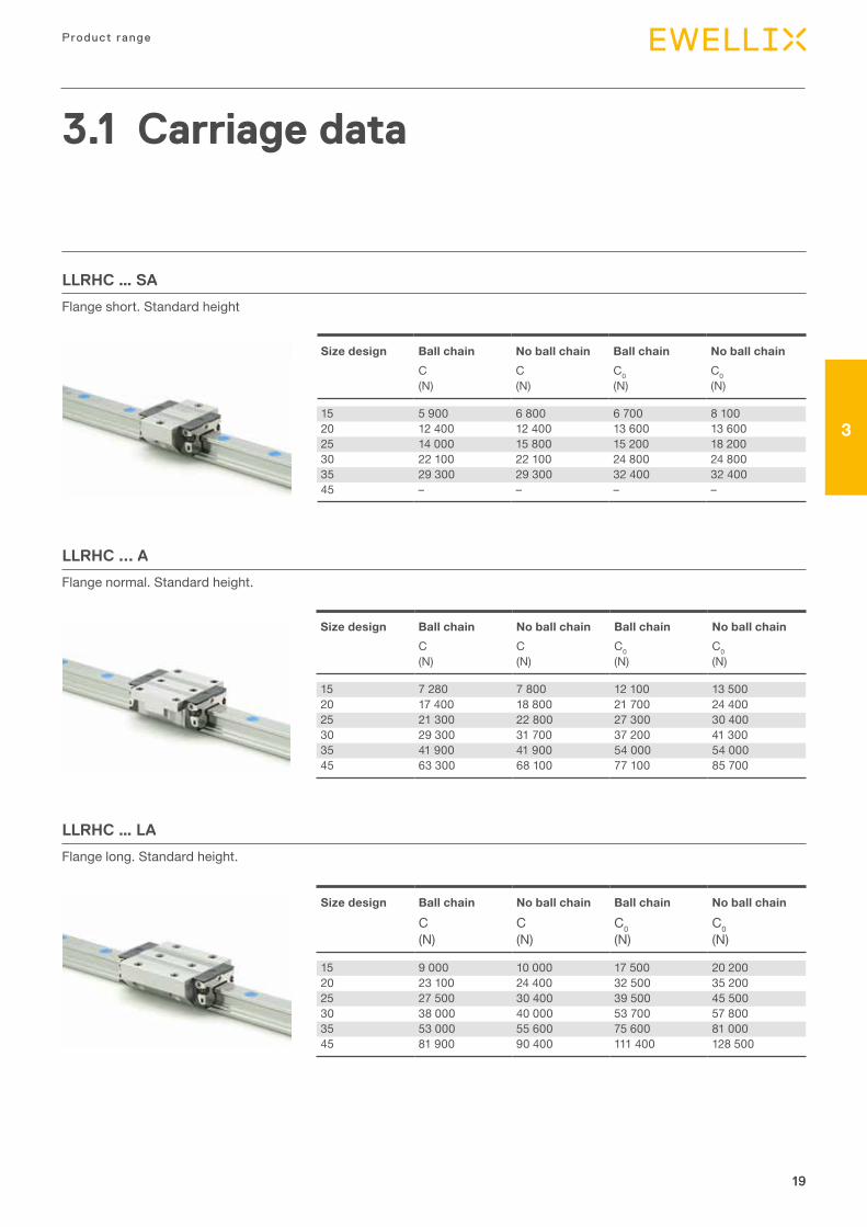
Size design Ball chain No ball chain Ball chain No ball chainC C C0 C0(N) (N) (N) (N)
15 5 900 6 800 6 700 8 10020 12 400 12 400 13 600 13 60025 14 000 15 800 15 200 18 20030 22 100 22 100 24 800 24 80035 29 300 29 300 32 400 32 40045 – – – –
Size design Ball chain No ball chain Ball chain No ball chainC C C0 C0(N) (N) (N) (N)
15 9 000 10 000 17 500 20 20020 23 100 24 400 32 500 35 20025 27 500 30 400 39 500 45 50030 38 000 40 000 53 700 57 80035 53 000 55 600 75 600 81 00045 81 900 90 400 111 400 128 500
Size design Ball chain No ball chain Ball chain No ball chainC C C0 C0(N) (N) (N) (N)
15 7 280 7 800 12 100 13 50020 17 400 18 800 21 700 24 40025 21 300 22 800 27 300 30 40030 29 300 31 700 37 200 41 30035 41 900 41 900 54 000 54 00045 63 300 68 100 77 100 85 700
LLRHC … SA
Flange short. Standard height
LLRHC … LA
Flange long. Standard height.
LLRHC ... A
Flange normal. Standard height.
3.1 Carriage data
20
Prof i le ra i l gu ides - LLR
20
Size design
Ball chain
No ball chain
Ball chain
No ball chain
C C C0 C0(N) (N) (N) (N)
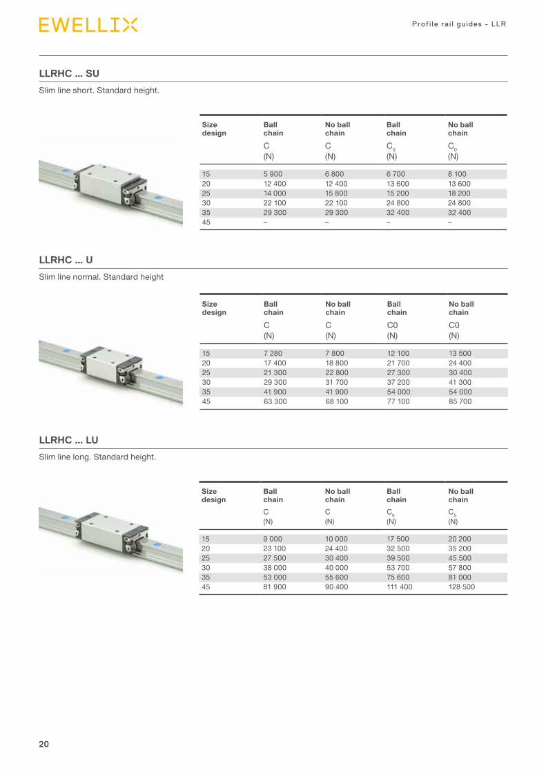
15 7 280 7 800 12 100 13 50020 17 400 18 800 21 700 24 40025 21 300 22 800 27 300 30 40030 29 300 31 700 37 200 41 30035 41 900 41 900 54 000 54 00045 63 300 68 100 77 100 85 700
LLRHC … U
Slim line normal. Standard height
Size design
Ball chain
No ball chain
Ball chain
No ball chain
C C C0 C0(N) (N) (N) (N)
15 9 000 10 000 17 500 20 20020 23 100 24 400 32 500 35 20025 27 500 30 400 39 500 45 50030 38 000 40 000 53 700 57 80035 53 000 55 600 75 600 81 00045 81 900 90 400 111 400 128 500
LLRHC … LU
Slim line long. Standard height.
Size design
Ball chain
No ball chain
Ball chain
No ball chain
C C C0 C0(N) (N) (N) (N)
15 5 900 6 800 6 700 8 10020 12 400 12 400 13 600 13 60025 14 000 15 800 15 200 18 20030 22 100 22 100 24 800 24 80035 29 300 29 300 32 400 32 40045 – – – –
LLRHC … SU
Slim line short. Standard height.
21
3
21
Product range
Size design Ball chain No ball chain Ball chain No ball chainC C C0 C0(N) (N) (N) (N)
15 7 280 7 800 12 100 13 50025 21 300 22 800 27 300 30 40030 29 300 31 700 37 200 41 30035 41 900 41 900 54 000 54 00045 63 300 68 100 77 100 85 700
Size design Ball chain No ball chain Ball chain No ball chainC C C0 C0(N) (N) (N) (N)
25 27 500 30 400 39 50 45 50030 38 000 40 000 53 700 57 80035 53 000 55 600 75 600 81 00045 81 900 90 400 111 400 128 500
Note on dynamic load capacities and momentsDetermination of dynamic load capacities and moments is based on a travel life of 100 000 m. However, frequently this is determined on the basis of only 50 000 m. In this case for comparison: multiply values C, MC and MA by 1.26 in accordance with Ewellix tables.For carriages with ball chain the permissible moments are reduced in accordance with the load ratings.
LLRHC … R
Slim line normal. High.
LLRHC … LR
Slim line long. High.
22
Prof i le ra i l gu ides - LLR
22
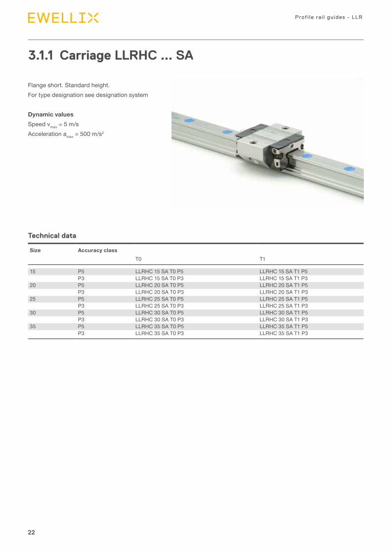
3.1.1 Carriage LLRHC ... SA
Flange short. Standard height.For type designation see designation system
Dynamic valuesSpeed vmax = 5 m/sAcceleration amax = 500 m/s2
Technical data
Size Accuracy classT0 T1
15 P5 LLRHC 15 SA T0 P5 LLRHC 15 SA T1 P5P3 LLRHC 15 SA T0 P3 LLRHC 15 SA T1 P3
20 P5 LLRHC 20 SA T0 P5 LLRHC 20 SA T1 P5P3 LLRHC 20 SA T0 P3 LLRHC 20 SA T1 P3
25 P5 LLRHC 25 SA T0 P5 LLRHC 25 SA T1 P5P3 LLRHC 25 SA T0 P3 LLRHC 25 SA T1 P3
30 P5 LLRHC 30 SA T0 P5 LLRHC 30 SA T1 P5P3 LLRHC 30 SA T0 P3 LLRHC 30 SA T1 P3
35 P5 LLRHC 35 SA T0 P5 LLRHC 35 SA T1 P5P3 LLRHC 35 SA T0 P3 LLRHC 35 SA T1 P3
23
3
23
Product range
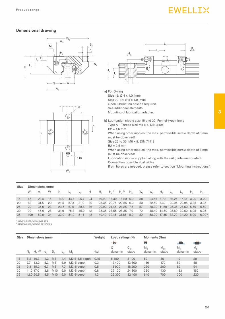
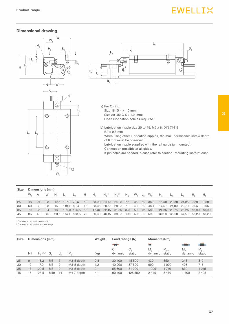
Dimensional drawing
H H1
H5H3
H4 H7
H9
L1
L4B2
A1
H8
W1W3S2
d4
d3
L2
L6
W2
a)
b)
N1
WN
M2
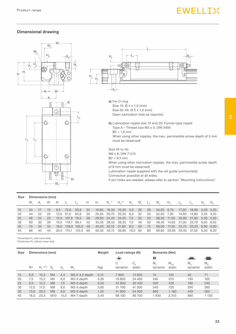
Size Dimensions (mm)W1 A1 W N L1 L2 H H1 H4 1) H4 2) H3 W2 W3 H5 L6 L4 H8 H9
15 47 23,5 15 16,0 44,7 25,7 24 19,90 16,30 16,20 5,0 38 24,55 6,70 16,25 17,85 3,20 3,2020 63 31,5 20 21,5 57,3 31,9 30 25,35 20,75 20,55 6,0 53 32,50 7,30 22,95 22,95 3,35 3,3525 70 35,0 23 23,5 67,0 38,6 36 29,90 24,45 24,25 7,5 57 38,30 11,50 25,35 26,50 5,50 5,5030 90 45,0 28 31,0 75,3 45,0 42 35,35 28,55 28,35 7,0 72 48,40 14,60 28,80 30,50 6,05 6,0535 100 50,0 34 33,0 84,9 51,4 48 40,40 32,15 31,85 8,0 82 58,00 17,35 32,70 34,20 6,90 6,901)
Size Dimensions (mm) Weight Load ratings (N) Moments (Nm)
C C0 MC MC0 MA MBN1 H7 ±0,5 d4 S2 d3 M2 (kg) dynamic static dynamic static dynamic static
15 5,2 10,3 4,3 M5 4,4 M2,5-3,5 depth 0,15 5 400 8 100 52 80 19 2820 7,7 13,2 5,3 M6 6,0 M3-5 depth 0,3 12 400 13 600 150 170 52 5825 9,3 15,2 6,7 M8 7,0 M3-5 depth 0,5 15 900 18 200 230 260 82 9430 11,0 17,0 8,5 M10 9,0 M3-5 depth 0,8 22 100 24 800 380 430 133 15035 12,0 20,5 8,5 M10 9,0 M3-5 depth 1,2 29 300 32 400 640 700 200 220
1) Dimension H4 with cover strip2) Dimension H4 without cover strip
a) For O-ring Size 15: Ø 4 x 1,0 (mm) Size 20-35: Ø 5 x 1,0 (mm) Open lubrication hole as required. See additional elements: Mounting of lubrication adapter.
b) Lubrication nipple size 15 and 20: Funnel-type nipple Type A – Thread size M3 x 5, DIN 3405 B2 = 1,6 mm When using other nipples, the max. permissible screw depth of 5 mm must be observed! Size 25 to 35: M6 x 8, DIN 71412 B2 = 9,5 mm When using other nipples, the max. permissible screw depth of 8 mm must be observed! Lubrication nipple supplied along with the rail guide (unmounted). Connection possible at all sides. If pin holes are needed, please refer to section "Mounting instructions".
24
Prof i le ra i l gu ides - LLR
24
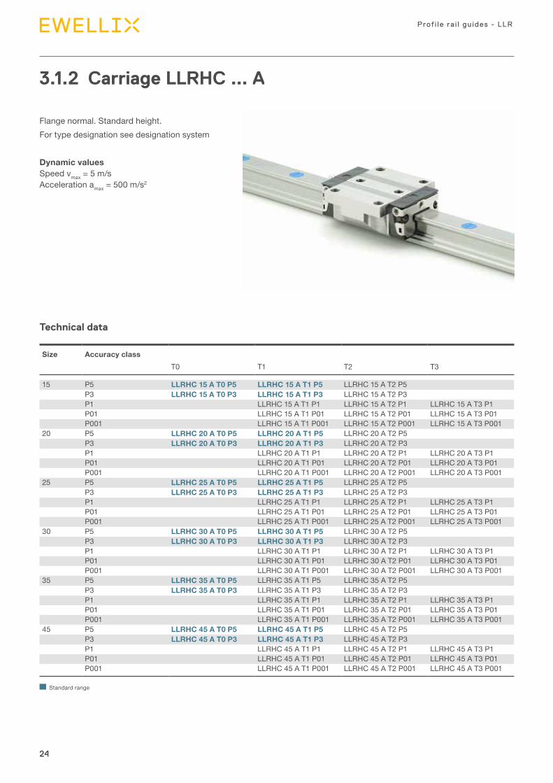
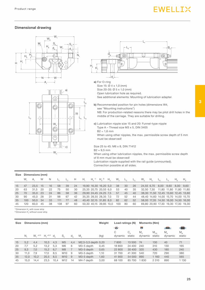
3.1.2 Carriage LLRHC ... A
Flange normal. Standard height.For type designation see designation system
Dynamic values Speed vmax = 5 m/s Acceleration amax = 500 m/s2
Size Accuracy classT0 T1 T2 T3
15 P5 LLRHC 15 A T0 P5 LLRHC 15 A T1 P5 LLRHC 15 A T2 P5P3 LLRHC 15 A T0 P3 LLRHC 15 A T1 P3 LLRHC 15 A T2 P3P1 LLRHC 15 A T1 P1 LLRHC 15 A T2 P1 LLRHC 15 A T3 P1P01 LLRHC 15 A T1 P01 LLRHC 15 A T2 P01 LLRHC 15 A T3 P01P001 LLRHC 15 A T1 P001 LLRHC 15 A T2 P001 LLRHC 15 A T3 P001
20 P5 LLRHC 20 A T0 P5 LLRHC 20 A T1 P5 LLRHC 20 A T2 P5P3 LLRHC 20 A T0 P3 LLRHC 20 A T1 P3 LLRHC 20 A T2 P3P1 LLRHC 20 A T1 P1 LLRHC 20 A T2 P1 LLRHC 20 A T3 P1P01 LLRHC 20 A T1 P01 LLRHC 20 A T2 P01 LLRHC 20 A T3 P01P001 LLRHC 20 A T1 P001 LLRHC 20 A T2 P001 LLRHC 20 A T3 P001
25 P5 LLRHC 25 A T0 P5 LLRHC 25 A T1 P5 LLRHC 25 A T2 P5P3 LLRHC 25 A T0 P3 LLRHC 25 A T1 P3 LLRHC 25 A T2 P3P1 LLRHC 25 A T1 P1 LLRHC 25 A T2 P1 LLRHC 25 A T3 P1P01 LLRHC 25 A T1 P01 LLRHC 25 A T2 P01 LLRHC 25 A T3 P01P001 LLRHC 25 A T1 P001 LLRHC 25 A T2 P001 LLRHC 25 A T3 P001
30 P5 LLRHC 30 A T0 P5 LLRHC 30 A T1 P5 LLRHC 30 A T2 P5P3 LLRHC 30 A T0 P3 LLRHC 30 A T1 P3 LLRHC 30 A T2 P3P1 LLRHC 30 A T1 P1 LLRHC 30 A T2 P1 LLRHC 30 A T3 P1P01 LLRHC 30 A T1 P01 LLRHC 30 A T2 P01 LLRHC 30 A T3 P01P001 LLRHC 30 A T1 P001 LLRHC 30 A T2 P001 LLRHC 30 A T3 P001
35 P5 LLRHC 35 A T0 P5 LLRHC 35 A T1 P5 LLRHC 35 A T2 P5P3 LLRHC 35 A T0 P3 LLRHC 35 A T1 P3 LLRHC 35 A T2 P3P1 LLRHC 35 A T1 P1 LLRHC 35 A T2 P1 LLRHC 35 A T3 P1P01 LLRHC 35 A T1 P01 LLRHC 35 A T2 P01 LLRHC 35 A T3 P01P001 LLRHC 35 A T1 P001 LLRHC 35 A T2 P001 LLRHC 35 A T3 P001
45 P5 LLRHC 45 A T0 P5 LLRHC 45 A T1 P5 LLRHC 45 A T2 P5P3 LLRHC 45 A T0 P3 LLRHC 45 A T1 P3 LLRHC 45 A T2 P3P1 LLRHC 45 A T1 P1 LLRHC 45 A T2 P1 LLRHC 45 A T3 P1P01 LLRHC 45 A T1 P01 LLRHC 45 A T2 P01 LLRHC 45 A T3 P01P001 LLRHC 45 A T1 P001 LLRHC 45 A T2 P001 LLRHC 45 A T3 P001
Standard range
Technical data
25
3
25
Product range
H H1
H5H3
A1
H8
W1W3
W7
S2S2
d4d4
N1
WN
M2
H4 H7
H9
L1
L4 B2
d3
L2
L6
L3L5
W4
W2
a)
b)
c)
Dimensional drawing
a) For O-ring Size 15: Ø 4 x 1,0 (mm) Size 20-35: Ø 5 x 1,0 (mm) Open lubrication hole as required. See additional elements: Mounting of lubrication adapter.
b) Recommended position for pin holes (dimensions W4, see “Mounting instructions”) NB: For production-related reasons there may be pilot drill holes in the middle of the carriage. They are suitable for drilling.
c) Lubrication nipple size 15 and 20: Funnel-type nipple Type A – Thread size M3 x 5, DIN 3405 B2 = 1,6 mm When using other nipples, the max. permissible screw depth of 5 mm must be observed!
Size 25 to 45: M6 x 8, DIN 71412 B2 = 9,5 mm When using other lubrication nipples, the max. permissible screw depth of 8 mm must be observed! Lubrication nipple supplied with the rail guide (unmounted). Connection possible at all sides.
Size Dimensions (mm)W1 A1 W N L1 L2 H H1 H4 1) H4 2) H3 W2 L3 L5 W3 H5 L6 L4 H8 H9
15 47 23,5 15 16 58 39 24 19,90 16,30 16,20 5,0 38 30 26 24,55 6,70 8,00 9,60 8,00 9,6020 63 31,5 20 22 75 50 30 25,35 20,75 20,55 6,0 53 40 35 32,50 7,30 11,80 11,80 11,80 11,8025 70 35,0 23 24 86 58 36 29,90 24,45 24,25 7,5 57 45 40 38,30 11,50 12,45 13,60 12,45 13,6030 90 45,0 28 31 98 67 42 35,35 28,55 28,35 7,0 72 52 44 48,40 14,60 14,00 15,70 14,00 15,7035 100 50,0 34 33 111 77 48 40,40 32,15 31,85 8,0 82 62 52 58,00 17,35 14,50 16,00 14,50 16,0045 120 60,0 45 38 138 97 60 50,30 40,15 39,85 10,0 100 80 60 69,80 20,90 17,30 19,30 17,30 19,30
Size Dimensions (mm) Weight Load ratings (N) Moments (Nm)
C C0 MC MC0 MA MBN1 W7 ±0,5 H7
±0,5 d4 S2 d3 M2 (kg) dynamic static dynamic static dynamic static
15 5,2 4,4 10,3 4,3 M5 4,4 M2,5-3,5 depth 0,20 7 800 13 500 74 130 40 7120 7,7 5,2 13,2 5,3 M6 6 M3-5 depth 0,45 18 800 24 400 240 310 130 16525 9,3 7,0 15,2 6,7 M8 7 M3-5 depth 0,65 22 800 30 400 320 430 180 24030 11,0 7,9 17,0 8,5 M10 9 M3-5 depth 1,10 31 700 41 300 540 720 290 38035 12,0 10,2 20,5 8,5 M10 9 M3-5 depth 1,60 41 900 54 000 890 1 160 440 56545 15,0 14,4 23,5 10,4 M12 14 M4-7 depth 3,00 68 100 85 700 1 830 2 310 890 1 130
1) Dimension H4 with cover strip2) Dimension H4 without cover strip
26
Prof i le ra i l gu ides - LLR
26
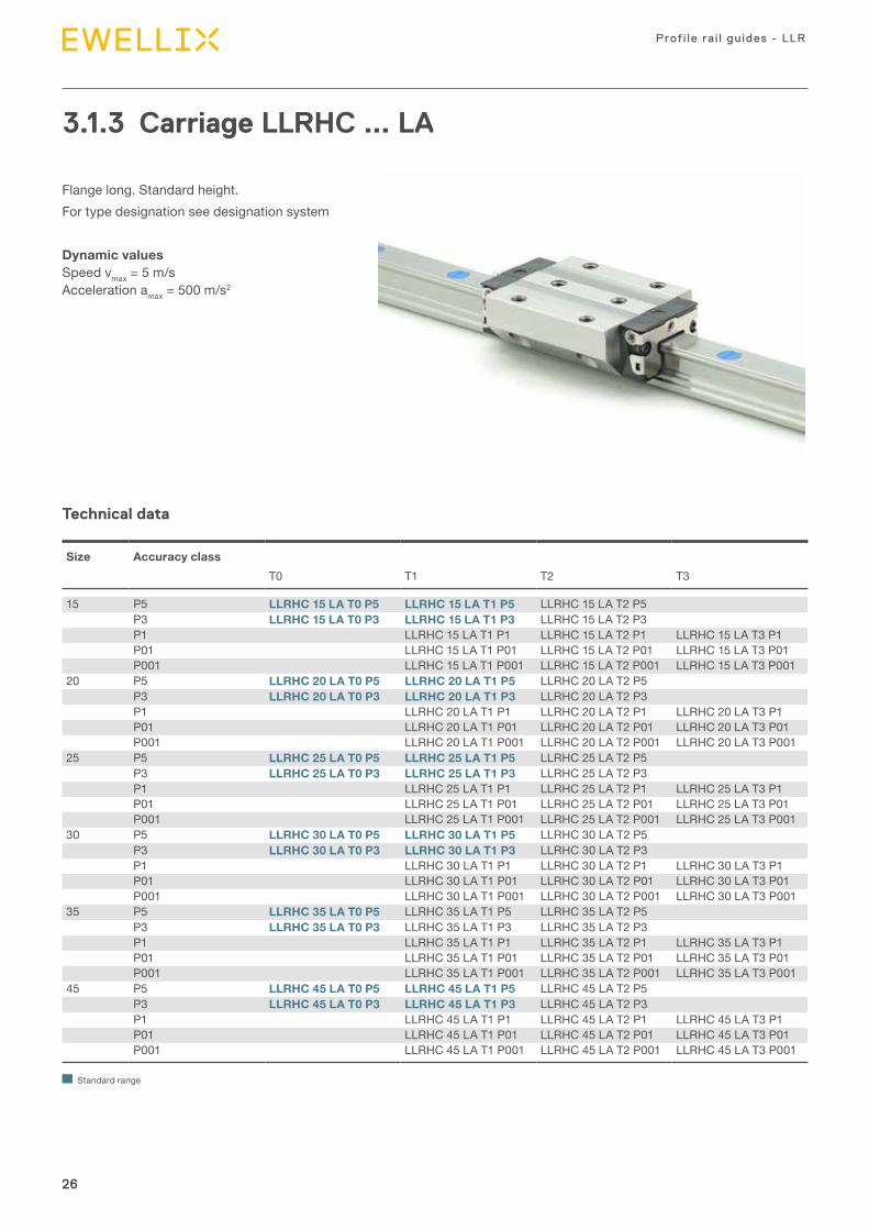
3.1.3 Carriage LLRHC ... LA
Flange long. Standard height.For type designation see designation system
Dynamic values Speed vmax = 5 m/s Acceleration amax = 500 m/s2
Technical data
Size Accuracy classT0 T1 T2 T3
15 P5 LLRHC 15 LA T0 P5 LLRHC 15 LA T1 P5 LLRHC 15 LA T2 P5P3 LLRHC 15 LA T0 P3 LLRHC 15 LA T1 P3 LLRHC 15 LA T2 P3P1 LLRHC 15 LA T1 P1 LLRHC 15 LA T2 P1 LLRHC 15 LA T3 P1P01 LLRHC 15 LA T1 P01 LLRHC 15 LA T2 P01 LLRHC 15 LA T3 P01P001 LLRHC 15 LA T1 P001 LLRHC 15 LA T2 P001 LLRHC 15 LA T3 P001
20 P5 LLRHC 20 LA T0 P5 LLRHC 20 LA T1 P5 LLRHC 20 LA T2 P5P3 LLRHC 20 LA T0 P3 LLRHC 20 LA T1 P3 LLRHC 20 LA T2 P3P1 LLRHC 20 LA T1 P1 LLRHC 20 LA T2 P1 LLRHC 20 LA T3 P1P01 LLRHC 20 LA T1 P01 LLRHC 20 LA T2 P01 LLRHC 20 LA T3 P01P001 LLRHC 20 LA T1 P001 LLRHC 20 LA T2 P001 LLRHC 20 LA T3 P001
25 P5 LLRHC 25 LA T0 P5 LLRHC 25 LA T1 P5 LLRHC 25 LA T2 P5P3 LLRHC 25 LA T0 P3 LLRHC 25 LA T1 P3 LLRHC 25 LA T2 P3P1 LLRHC 25 LA T1 P1 LLRHC 25 LA T2 P1 LLRHC 25 LA T3 P1P01 LLRHC 25 LA T1 P01 LLRHC 25 LA T2 P01 LLRHC 25 LA T3 P01P001 LLRHC 25 LA T1 P001 LLRHC 25 LA T2 P001 LLRHC 25 LA T3 P001
30 P5 LLRHC 30 LA T0 P5 LLRHC 30 LA T1 P5 LLRHC 30 LA T2 P5P3 LLRHC 30 LA T0 P3 LLRHC 30 LA T1 P3 LLRHC 30 LA T2 P3P1 LLRHC 30 LA T1 P1 LLRHC 30 LA T2 P1 LLRHC 30 LA T3 P1P01 LLRHC 30 LA T1 P01 LLRHC 30 LA T2 P01 LLRHC 30 LA T3 P01P001 LLRHC 30 LA T1 P001 LLRHC 30 LA T2 P001 LLRHC 30 LA T3 P001
35 P5 LLRHC 35 LA T0 P5 LLRHC 35 LA T1 P5 LLRHC 35 LA T2 P5P3 LLRHC 35 LA T0 P3 LLRHC 35 LA T1 P3 LLRHC 35 LA T2 P3P1 LLRHC 35 LA T1 P1 LLRHC 35 LA T2 P1 LLRHC 35 LA T3 P1P01 LLRHC 35 LA T1 P01 LLRHC 35 LA T2 P01 LLRHC 35 LA T3 P01P001 LLRHC 35 LA T1 P001 LLRHC 35 LA T2 P001 LLRHC 35 LA T3 P001
45 P5 LLRHC 45 LA T0 P5 LLRHC 45 LA T1 P5 LLRHC 45 LA T2 P5P3 LLRHC 45 LA T0 P3 LLRHC 45 LA T1 P3 LLRHC 45 LA T2 P3P1 LLRHC 45 LA T1 P1 LLRHC 45 LA T2 P1 LLRHC 45 LA T3 P1P01 LLRHC 45 LA T1 P01 LLRHC 45 LA T2 P01 LLRHC 45 LA T3 P01P001 LLRHC 45 LA T1 P001 LLRHC 45 LA T2 P001 LLRHC 45 LA T3 P001
Standard range
27
3
27
Product range
H H1
H5H3
A1
H8
W1W3
W7
S2S2
d4d4
N1
WN
M2
H4 H7
H9
L1
L4 B2
d3
L2
L6
L3L5
W4
W2
a)
b)
c)
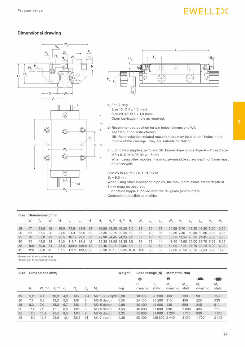
Dimensional drawing
a) For O-ring Size 15: Ø 4 x 1,0 (mm) Size 20-45: Ø 5 x 1,0 (mm) Open lubrication hole as required.
b) Recommended position for pin holes (dimensions W4, see “Mounting instructions”) NB: For production-related reasons there may be pilot drill holes in the middle of the carriage. They are suitable for drilling.
c) Lubrication nipple size 15 and 20: Funnel-type nipple Type A – Thread size M3 x 5, DIN 3405 B2 = 1.6 mm When using other nipples, the max. permissible screw depth of 5 mm must be observed!
Size 25 to 45: M6 x 8, DIN 71412 B2 = 9.5 mm When using other lubrication nipples, the max. permissible screw depth of 8 mm must be observed! Lubrication nipple supplied with the rail guide (unmounted). Connection possible at all sides.
Size Dimensions (mm)W1 A1 W N L1 L2 H H1 H4 1) H4 2) H3 W2 L3 L5 W3 H5 L6 L4 H8 H9
15 47 23,5 15 16,0 72,6 53,6 24 19,90 16,30 16,20 5,0 38 30 26 24,55 6,70 15,20 16,80 3,20 3,2020 63 31,5 20 21,5 91,0 65,6 30 25,35 20,75 20,55 6,0 53 40 35 32,50 7,30 19,80 19,80 3,35 3,3525 70 35,0 23 23,5 107,9 79,5 36 29,90 24,45 24,25 7,5 57 45 40 38,30 11,50 23,30 24,45 5,50 5,5030 90 45,0 28 31,0 119,7 89,4 42 35,35 28,55 28,35 7,0 72 52 44 48,40 14,60 25,00 26,70 6,05 6,0535 100 50,0 34 33,0 139,0 105,5 48 40,40 32,15 31,85 8,0 82 62 52 58,00 17,35 28,75 30,25 6,90 6,9045 120 60,0 45 37,5 174,1 133,5 60 50,30 40,15 39,85 10,0 100 80 60 69,80 20,90 35,50 37,50 8,20 8,20
Size Dimensions (mm) Weight Load ratings (N) Moments (Nm)
C C0 MC MC0 MA MBN1 W7 ±0,5 H7
±0,5 d4 S2 d3 M2 (kg) dynamic static dynamic static dynamic static
15 5,2 4,4 10,3 4,3 M5 4,4 M2,5-3,5 depth 0,30 10 000 20 200 130 190 98 15020 7,7 5,2 13,2 5,3 M6 6 M3-5 depth 0,55 24 400 35 200 310 450 225 33025 9,3 7,0 15,2 6,7 M8 7 M3-5 depth 0,90 30 400 45 500 430 650 345 51030 11,0 7,9 17,0 8,5 M10 9 M3-5 depth 1,50 40 000 57 800 690 1 000 495 71535 12,0 10,2 20,5 8,5 M10 9 M3-5 depth 2,25 55 600 81 000 1 200 1 740 830 1 21545 15,0 12,4 23,5 10,4 M12 14 M4-7 depth 4,30 90 400 128 500 2 440 3 470 1 700 2 425
1) Dimension H4 with cover strip2) Dimension H4 without cover strip
28
Prof i le ra i l gu ides - LLR
28
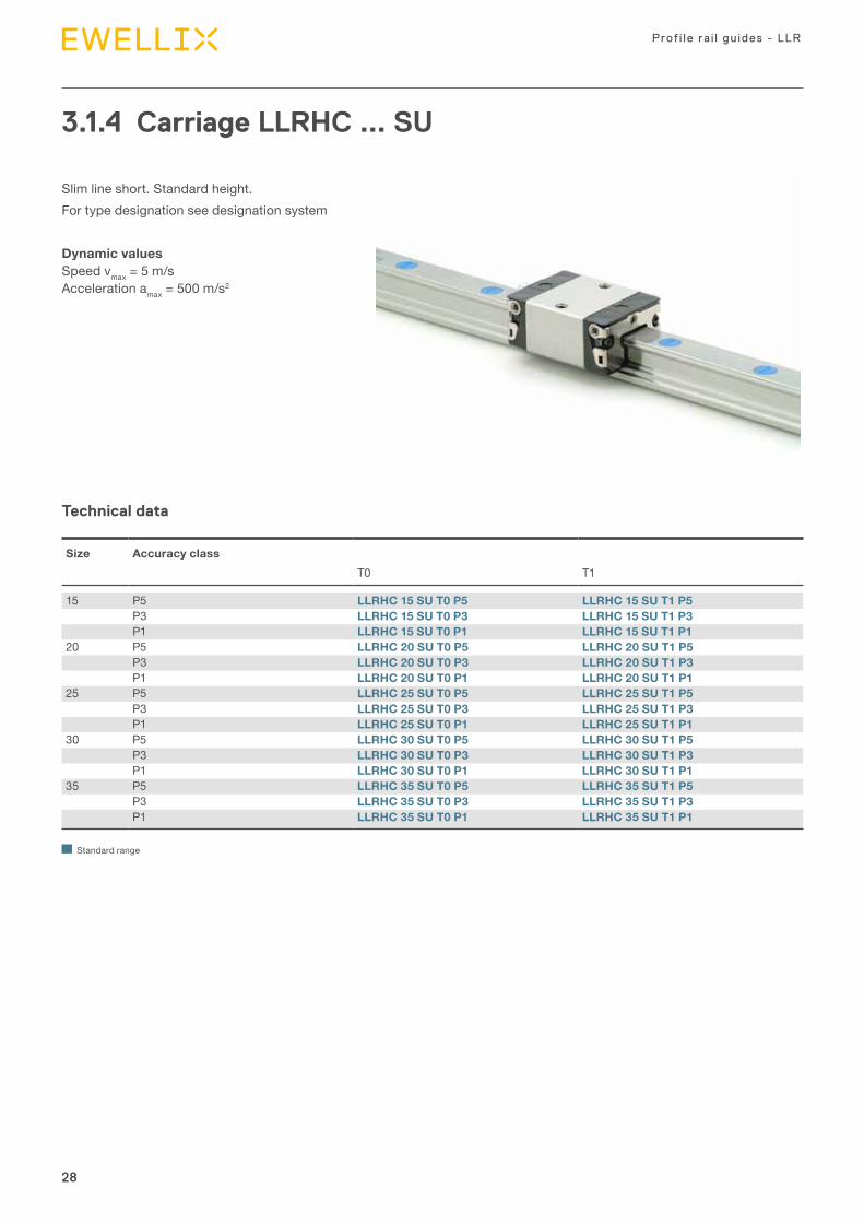
3.1.4 Carriage LLRHC ... SU
Slim line short. Standard height.For type designation see designation system
Dynamic values Speed vmax = 5 m/s Acceleration amax = 500 m/s2
Technical data
Size Accuracy classT0 T1
15 P5 LLRHC 15 SU T0 P5 LLRHC 15 SU T1 P5P3 LLRHC 15 SU T0 P3 LLRHC 15 SU T1 P3P1 LLRHC 15 SU T0 P1 LLRHC 15 SU T1 P1
20 P5 LLRHC 20 SU T0 P5 LLRHC 20 SU T1 P5P3 LLRHC 20 SU T0 P3 LLRHC 20 SU T1 P3P1 LLRHC 20 SU T0 P1 LLRHC 20 SU T1 P1
25 P5 LLRHC 25 SU T0 P5 LLRHC 25 SU T1 P5P3 LLRHC 25 SU T0 P3 LLRHC 25 SU T1 P3P1 LLRHC 25 SU T0 P1 LLRHC 25 SU T1 P1
30 P5 LLRHC 30 SU T0 P5 LLRHC 30 SU T1 P5P3 LLRHC 30 SU T0 P3 LLRHC 30 SU T1 P3P1 LLRHC 30 SU T0 P1 LLRHC 30 SU T1 P1
35 P5 LLRHC 35 SU T0 P5 LLRHC 35 SU T1 P5P3 LLRHC 35 SU T0 P3 LLRHC 35 SU T1 P3P1 LLRHC 35 SU T0 P1 LLRHC 35 SU T1 P1
Standard range
29
3
29
Product range
HH1
H5H3
A1
H8
W1W3
S2
N1
WN
M2
H4 H7
H9
L1
L4 B2
d3
L2
L6
W2
a)
b)
Dimensional drawing
a) For O-ring Size 15: Ø 4 x 1,0 (mm) Size 20-35: Ø 5 x 1,0 (mm) Open lubrication hole as required.
b) Lubrication nipple size 15 and 20: Funnel-type nipple Type A – Thread size M3 x 5, DIN 3405 B2 = 1,6 mm When using other nipples, the max. permissible screw depth of 5 mm must be observed! Size 25 to 35: M6 x 8, DIN 71412 B2 = 9,5 mm When using other lubrication nipples, the max. permissible screw depth of 8 mm must be observed! Lubrication nipple supplied with the rail guide (unmounted). Connection possible at all sides. If pin holes are needed, please refer to section "Mounting instructions".
Size Dimensions (mm)W1 A1 W N L1 L2 H H1 H4 1) H4 2) H3 W2 W3 H5 L6 L4 H8 H9
15 34 17 15 9,5 44,7 25,7 24 19,90 16,30 16,20 5,0 26 24,55 6,70 16,25 17,85 3,20 3,2020 44 22 20 12,0 57,3 31,9 30 25,35 20,75 20,55 6,0 32 32,50 7,30 22,95 22,95 3,35 3,3525 48 24 23 12,5 67,0 38,6 36 29,90 24,45 24,25 7,5 35 38,30 11,50 25,35 26,50 5,50 5,5030 60 30 28 16,0 75,3 45,0 42 35,35 28,55 28,35 7,0 40 48,40 14,60 28,80 30,50 6,05 6,0535 70 35 34 18,0 84,9 51,4 48 40,40 32,15 31,85 8,0 50 58,00 17,35 32,70 34,20 6,90 6,901)
Size Dimensions (mm) Weight Load ratings (N) Moments (Nm)
C C0 MC MC0 MA MBN1 H7
±0,5 S2 d3 M2 (kg) dynamic static dynamic static dynamic static
15 6,0 10,3 M4 4,4 M2,5-3,5 depth 0,10 5 400 8 100 52 80 19 2820 7,5 13,2 M5 6,0 M3-5 depth 0,25 12 400 13 600 150 170 52 5825 9,0 15,2 M6 7,0 M3-5 depth 0,35 15 900 18 200 230 260 82 9430 12,0 17,0 M8 9,0 M3-5 depth 0,60 22 100 24 800 380 430 133 15035 13,0 20,5 M8 9,0 M3-5 depth 0,90 29 300 32 400 640 700 200 220
1) Dimension H4 with cover strip2) Dimension H4 without cover strip
30
Prof i le ra i l gu ides - LLR
30
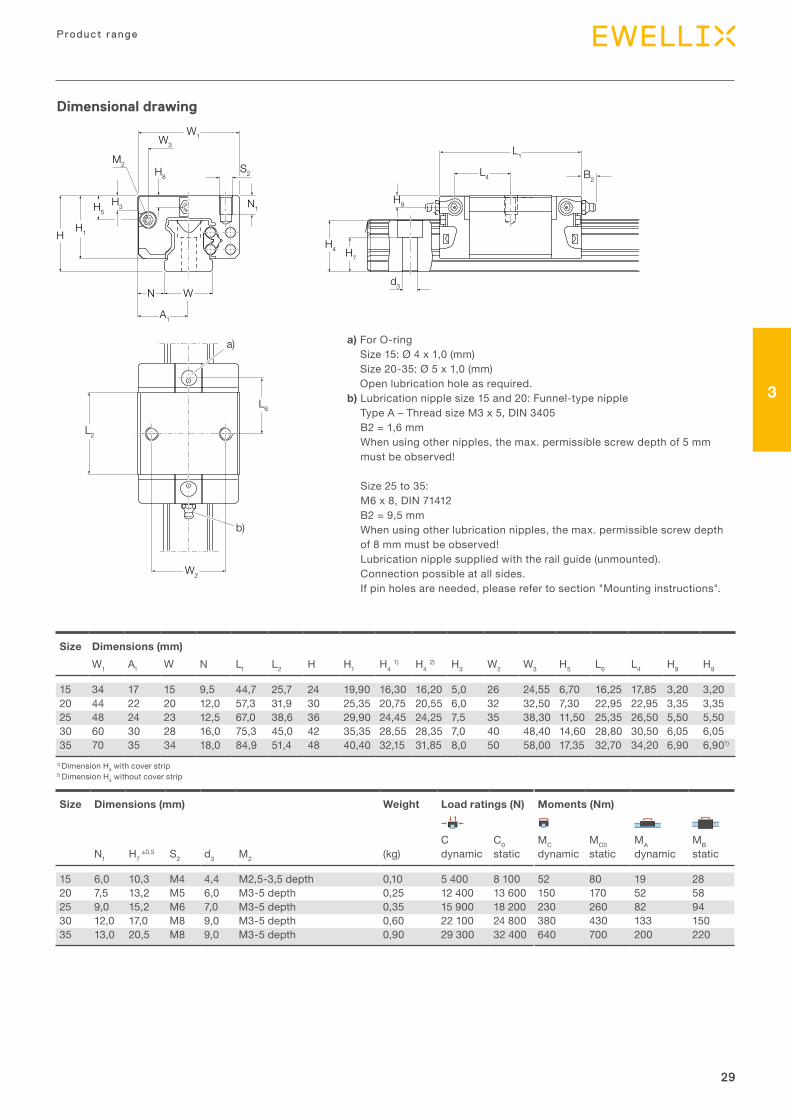
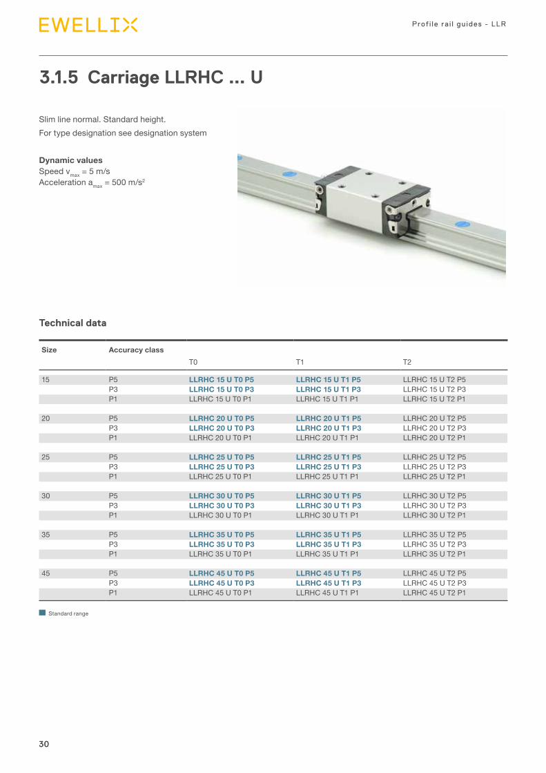
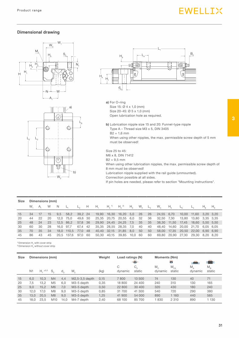
3.1.5 Carriage LLRHC ... U
Slim line normal. Standard height.For type designation see designation system
Dynamic values Speed vmax = 5 m/s Acceleration amax = 500 m/s2
Technical data
Size Accuracy classT0 T1 T2
15 P5 LLRHC 15 U T0 P5 LLRHC 15 U T1 P5 LLRHC 15 U T2 P5P3 LLRHC 15 U T0 P3 LLRHC 15 U T1 P3 LLRHC 15 U T2 P3P1 LLRHC 15 U T0 P1 LLRHC 15 U T1 P1 LLRHC 15 U T2 P1
20 P5 LLRHC 20 U T0 P5 LLRHC 20 U T1 P5 LLRHC 20 U T2 P5P3 LLRHC 20 U T0 P3 LLRHC 20 U T1 P3 LLRHC 20 U T2 P3P1 LLRHC 20 U T0 P1 LLRHC 20 U T1 P1 LLRHC 20 U T2 P1
25 P5 LLRHC 25 U T0 P5 LLRHC 25 U T1 P5 LLRHC 25 U T2 P5P3 LLRHC 25 U T0 P3 LLRHC 25 U T1 P3 LLRHC 25 U T2 P3P1 LLRHC 25 U T0 P1 LLRHC 25 U T1 P1 LLRHC 25 U T2 P1
30 P5 LLRHC 30 U T0 P5 LLRHC 30 U T1 P5 LLRHC 30 U T2 P5P3 LLRHC 30 U T0 P3 LLRHC 30 U T1 P3 LLRHC 30 U T2 P3P1 LLRHC 30 U T0 P1 LLRHC 30 U T1 P1 LLRHC 30 U T2 P1
35 P5 LLRHC 35 U T0 P5 LLRHC 35 U T1 P5 LLRHC 35 U T2 P5P3 LLRHC 35 U T0 P3 LLRHC 35 U T1 P3 LLRHC 35 U T2 P3P1 LLRHC 35 U T0 P1 LLRHC 35 U T1 P1 LLRHC 35 U T2 P1
45 P5 LLRHC 45 U T0 P5 LLRHC 45 U T1 P5 LLRHC 45 U T2 P5P3 LLRHC 45 U T0 P3 LLRHC 45 U T1 P3 LLRHC 45 U T2 P3P1 LLRHC 45 U T0 P1 LLRHC 45 U T1 P1 LLRHC 45 U T2 P1
Standard range
31
3
31
Product range
HH1
H5H3
A1
H8
W1W3
S2
N1
WN
M2
H4 H7
H9
L1
L4B2
d3
L2 L3
L6
W2
a)
b)
Dimensional drawing
Size Dimensions (mm)W1 A1 W N L1 L2 H H1 H4 1) H4 2) H3 W2 L3 W3 H5 L6 L4 H8 H9
15 34 17 15 9,5 58,2 39,2 24 19,90 16,30 16,20 5,0 26 26 24,55 6,70 10,00 11,60 3,20 3,2020 44 22 20 12,0 75,0 49,6 30 25,35 20,75 20,55 6,0 32 36 32,50 7,30 13,80 13,80 3,35 3,3525 48 24 23 12,5 86,2 57,8 36 29,90 24,45 24,25 7,5 35 35 38,30 11,50 17,45 18,60 5,50 5,5030 60 30 28 16,0 97,7 67,4 42 35,35 28,55 28,35 7,0 40 40 48,40 14,60 20,00 21,70 6,05 6,0535 70 35 34 18,0 110,5 77,0 48 40,40 32,15 31,85 8,0 50 50 58,00 17,35 20,50 22,00 6,90 6,9045 86 43 45 20,5 137,6 97,0 60 50,30 40,15 39,85 10,0 60 60 69,80 20,90 27,30 29,30 8,20 8,20
Size Dimensions (mm) Weight Load ratings (N) Moments (Nm)
C C0 MC MC0 MA MBN1 H7 ±0,5 S2 d3 M2 (kg) dynamic static dynamic static dynamic static
15 6,0 10,3 M4 4,4 M2,5-3,5 depth 0,15 7 800 13 500 74 130 40 7120 7,5 13,2 M5 6,0 M3-5 depth 0,35 18 800 24 400 240 310 130 16525 9,0 15,2 M6 7,0 M3-5 depth 0,50 22 800 30 400 320 430 180 24030 12,0 17,0 M8 9,0 M3-5 depth 0,85 31 700 41 300 540 720 290 38035 13,0 20,5 M8 9,0 M3-5 depth 1,25 41 900 54 000 890 1 160 440 56545 18,0 23,5 M10 14,0 M4-7 depth 2,40 68 100 85 700 1 830 2 310 890 1 130
1) Dimension H4 with cover strip2) Dimension H4 without cover strip
a) For O-ring Size 15: Ø 4 x 1,0 (mm) Size 20-45: Ø 5 x 1,0 (mm) Open lubrication hole as required.
b) Lubrication nipple size 15 and 20: Funnel-type nipple Type A – Thread size M3 x 5, DIN 3405 B2 = 1,6 mm When using other nipples, the max. permissible screw depth of 5 mm must be observed!
Size 25 to 45: M6 x 8, DIN 71412 B2 = 9,5 mm When using other lubrication nipples, the max. permissible screw depth of 8 mm must be observed! Lubrication nipple supplied with the rail guide (unmounted). Connection possible at all sides. If pin holes are needed, please refer to section "Mounting instructions".
32
Prof i le ra i l gu ides - LLR
32
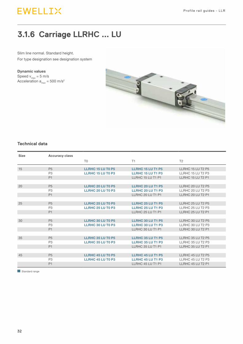
3.1.6 Carriage LLRHC ... LU
Slim line normal. Standard height.For type designation see designation system
Dynamic values Speed vmax = 5 m/s Acceleration amax = 500 m/s2
Technical data
Size Accuracy classT0 T1 T2
15 P5 LLRHC 15 LU T0 P5 LLRHC 15 LU T1 P5 LLRHC 15 LU T2 P5P3 LLRHC 15 LU T0 P3 LLRHC 15 LU T1 P3 LLRHC 15 LU T2 P3P1 LLRHC 15 LU T1 P1 LLRHC 15 LU T2 P1
20 P5 LLRHC 20 LU T0 P5 LLRHC 20 LU T1 P5 LLRHC 20 LU T2 P5P3 LLRHC 20 LU T0 P3 LLRHC 20 LU T1 P3 LLRHC 20 LU T2 P3P1 LLRHC 20 LU T1 P1 LLRHC 20 LU T2 P1
25 P5 LLRHC 25 LU T0 P5 LLRHC 25 LU T1 P5 LLRHC 25 LU T2 P5P3 LLRHC 25 LU T0 P3 LLRHC 25 LU T1 P3 LLRHC 25 LU T2 P3P1 LLRHC 25 LU T1 P1 LLRHC 25 LU T2 P1
30 P5 LLRHC 30 LU T0 P5 LLRHC 30 LU T1 P5 LLRHC 30 LU T2 P5P3 LLRHC 30 LU T0 P3 LLRHC 30 LU T1 P3 LLRHC 30 LU T2 P3P1 LLRHC 30 LU T1 P1 LLRHC 30 LU T2 P1
35 P5 LLRHC 35 LU T0 P5 LLRHC 35 LU T1 P5 LLRHC 35 LU T2 P5P3 LLRHC 35 LU T0 P3 LLRHC 35 LU T1 P3 LLRHC 35 LU T2 P3P1 LLRHC 35 LU T1 P1 LLRHC 35 LU T2 P1
45 P5 LLRHC 45 LU T0 P5 LLRHC 45 LU T1 P5 LLRHC 45 LU T2 P5P3 LLRHC 45 LU T0 P3 LLRHC 45 LU T1 P3 LLRHC 45 LU T2 P3P1 LLRHC 45 LU T1 P1 LLRHC 45 LU T2 P1
Standard range
33
3
33
Product range
HH1
H5H3
A1
H8
W1W3
S2
N1
WN
M2
H4 H7
H9
L1
L4 B2
d3
L2 L3
L6
W2
a)
b)
Dimensional drawing
Size Dimensions (mm)W1 A1 W N L1 L2 H H1 H4 1) H4 2) H3 W2 L3 W3 H5 L6 L4 H8 H9
15 34 17 15 9,5 72,6 53,6 24 19,90 16,30 16,20 5,0 26 26 24,55 6,70 17,20 18,80 3,20 3,2020 44 22 20 12,0 91,0 65,6 30 25,35 20,75 20,55 6,0 32 50 32,50 7,30 14,80 14,80 3,35 3,3525 48 24 23 12,5 107,9 79,5 36 29,90 24,45 24,25 7,5 35 50 38,30 11,50 20,80 21,95 5,50 5,5030 60 30 28 16,0 119,7 89,4 42 35,35 28,55 28,35 7,0 40 60 48,40 14,60 21,00 22,70 6,05 6,0535 70 35 34 18,0 139,0 105,5 48 40,40 32,15 31,85 8,0 50 72 58,00 17,35 23,75 25,25 6,90 6,9045 86 43 45 20,5 174,1 133,5 60 50,30 40,15 39,85 10,0 60 80 69,80 20,90 35,50 37,50 8,20 8,20
Size Dimensions (mm) Weight Load ratings (N) Moments (Nm)
C C0 MC MC0 MA MBN1 H7 ±0,5 S2 d3 M2 (kg) dynamic static dynamic static dynamic static
15 6,0 10,3 M4 4,4 M2,5-3,5 depth 0,15 7 800 13 500 74 130 40 7120 7,5 13,2 M5 6,0 M3-5 depth 0,35 18 800 24 400 240 310 130 16525 9,0 15,2 M6 7,0 M3-5 depth 0,50 22 800 30 400 320 430 180 24030 12,0 17,0 M8 9,0 M3-5 depth 0,85 31 700 41 300 540 720 290 38035 13,0 20,5 M8 9,0 M3-5 depth 1,25 41 900 54 000 890 1 160 440 56545 18,0 23,5 M10 14,0 M4-7 depth 2,40 68 100 85 700 1 830 2 310 890 1 130
1) Dimension H4 with cover strip2) Dimension H4 without cover strip
a) For O-ring Size 15: Ø 4 x 1,0 (mm) Size 20-45: Ø 5 x 1,0 (mm) Open lubrication hole as required.
b) Lubrication nipple size 15 and 20: Funnel-type nipple Type A – Thread size M3 x 5, DIN 3405 B2 = 1,6 mm When using other nipples, the max. permissible screw depth of 5 mm must be observed!
Size 25 to 45: M6 x 8, DIN 71412 B2 = 9,5 mm When using other lubrication nipples, the max. permissible screw depth of 8 mm must be observed! Lubrication nipple supplied with the rail guide (unmounted). Connection possible at all sides. If pin holes are needed, please refer to section "Mounting instructions".
34
Prof i le ra i l gu ides - LLR
34
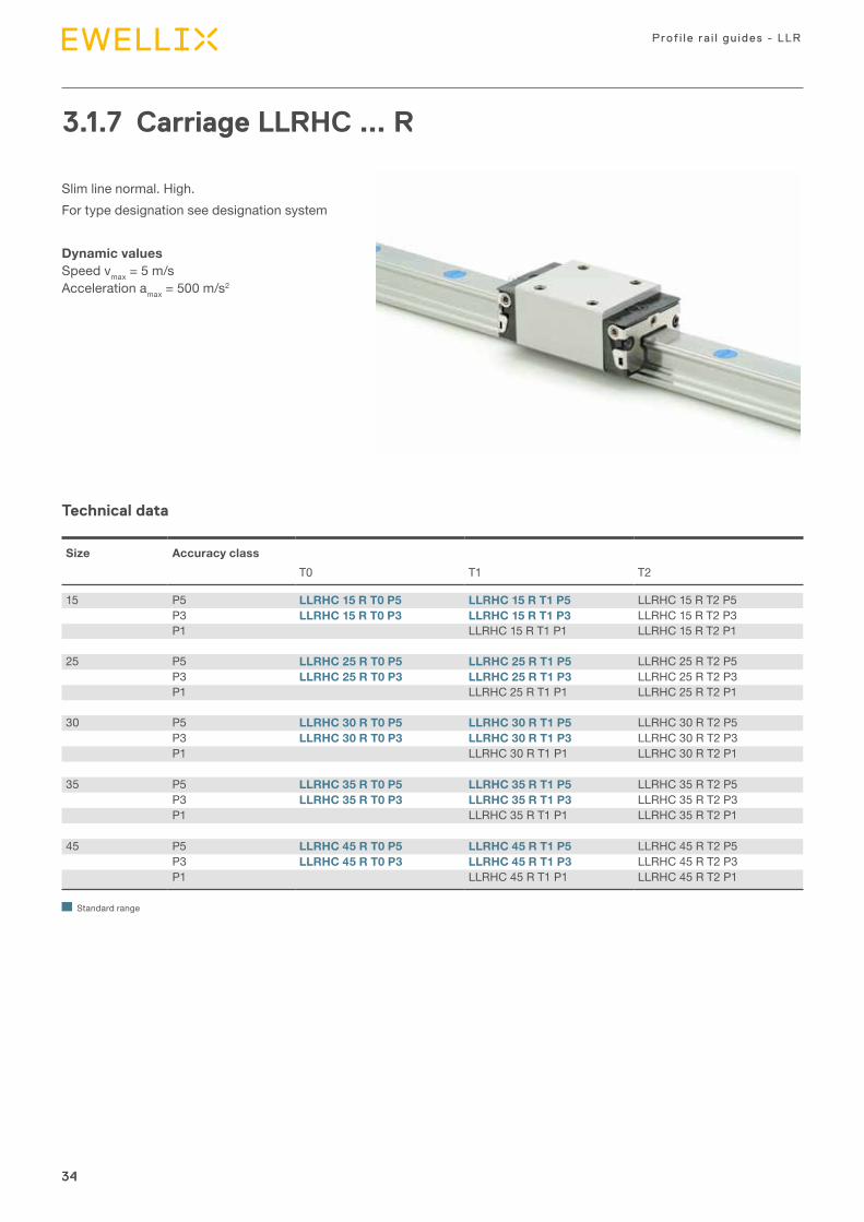
3.1.7 Carriage LLRHC ... R
Slim line normal. High.For type designation see designation system
Dynamic values Speed vmax = 5 m/s Acceleration amax = 500 m/s2
Technical data
Size Accuracy classT0 T1 T2
15 P5 LLRHC 15 R T0 P5 LLRHC 15 R T1 P5 LLRHC 15 R T2 P5P3 LLRHC 15 R T0 P3 LLRHC 15 R T1 P3 LLRHC 15 R T2 P3P1 LLRHC 15 R T1 P1 LLRHC 15 R T2 P1
25 P5 LLRHC 25 R T0 P5 LLRHC 25 R T1 P5 LLRHC 25 R T2 P5P3 LLRHC 25 R T0 P3 LLRHC 25 R T1 P3 LLRHC 25 R T2 P3P1 LLRHC 25 R T1 P1 LLRHC 25 R T2 P1
30 P5 LLRHC 30 R T0 P5 LLRHC 30 R T1 P5 LLRHC 30 R T2 P5P3 LLRHC 30 R T0 P3 LLRHC 30 R T1 P3 LLRHC 30 R T2 P3P1 LLRHC 30 R T1 P1 LLRHC 30 R T2 P1
35 P5 LLRHC 35 R T0 P5 LLRHC 35 R T1 P5 LLRHC 35 R T2 P5P3 LLRHC 35 R T0 P3 LLRHC 35 R T1 P3 LLRHC 35 R T2 P3P1 LLRHC 35 R T1 P1 LLRHC 35 R T2 P1
45 P5 LLRHC 45 R T0 P5 LLRHC 45 R T1 P5 LLRHC 45 R T2 P5P3 LLRHC 45 R T0 P3 LLRHC 45 R T1 P3 LLRHC 45 R T2 P3P1 LLRHC 45 R T1 P1 LLRHC 45 R T2 P1
Standard range
35
3
35
Product range
H H1
H5
H3
A1
H8
W1W3
S2
N1
WN
M2
H4 H7
H9
L1
L4 B2
d3
L2 L3
L6
W2
a)
b)
Dimensional drawing
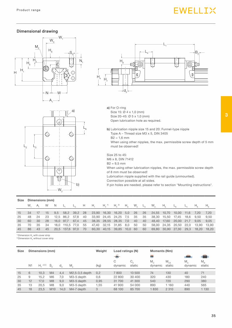
Size Dimensions (mm)W1 A1 W N L1 L2 H H1 H4 1) H4 2) H3 W2 L3 W3 H5 L6 L4 H8 H9
15 34 17 15 9,5 58,2 39,2 28 23,90 16,30 16,20 5,0 26 26 24,55 10,70 10,00 11,6 7,20 7,2025 48 24 23 12,5 86,2 57,8 40 33,90 24,45 24,25 7,5 35 35 38,30 15,50 17,45 18,6 9,50 9,5030 60 30 28 16,0 97,7 67,4 45 38,35 28,55 28,35 7,0 40 40 48,40 17,60 20,00 21,7 9,05 9,0535 70 35 34 18,0 110,5 77,0 55 47,40 32,15 31,85 8,0 50 50 58,00 24,35 20,50 22,0 13,90 13,9045 86 43 45 20,5 137,6 97,0 70 60,30 40,15 39,85 10,0 60 60 69,80 30,90 27,30 29,3 18,20 18,20
Size Dimensions (mm) Weight Load ratings (N) Moments (Nm)
C C0 MC MC0 MA MBN1 H7 ±0,5 S2 d3 M2 (kg) dynamic static dynamic static dynamic static
15 6 10,3 M4 4,4 M2,5-3,5 depth 0,2 7 800 13 500 74 130 40 7125 9 15,2 M6 7,0 M3-5 depth 0,6 22 800 30 400 320 430 180 24030 12 17,0 M8 9,0 M3-5 depth 0,95 31 700 41 300 540 720 290 38035 13 20,5 M8 9,0 M3-5 depth 1,55 41 900 54 000 890 1 160 440 56545 18 23,5 M10 14,0 M4-7 depth 3 68 100 85 700 1 830 2 310 890 1 130
1) Dimension H4 with cover strip2) Dimension H4 without cover strip
a) For O-ring Size 15: Ø 4 x 1,0 (mm) Size 20-45: Ø 5 x 1,0 (mm) Open lubrication hole as required.
b) Lubrication nipple size 15 and 20: Funnel-type nipple Type A – Thread size M3 x 5, DIN 3405 B2 = 1,6 mm When using other nipples, the max. permissible screw depth of 5 mm must be observed!
Size 25 to 45: M6 x 8, DIN 71412 B2 = 9,5 mm When using other lubrication nipples, the max. permissible screw depth of 8 mm must be observed! Lubrication nipple supplied with the rail guide (unmounted). Connection possible at all sides. If pin holes are needed, please refer to section "Mounting instructions".
36
Prof i le ra i l gu ides - LLR
36
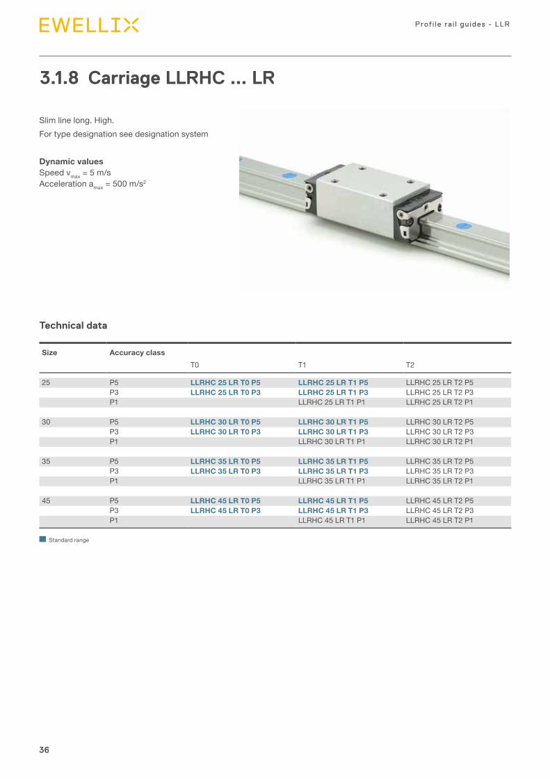
3.1.8 Carriage LLRHC ... LR
Slim line long. High.For type designation see designation system
Dynamic values Speed vmax = 5 m/s Acceleration amax = 500 m/s2
Technical data
Size Accuracy classT0 T1 T2
25 P5 LLRHC 25 LR T0 P5 LLRHC 25 LR T1 P5 LLRHC 25 LR T2 P5P3 LLRHC 25 LR T0 P3 LLRHC 25 LR T1 P3 LLRHC 25 LR T2 P3P1 LLRHC 25 LR T1 P1 LLRHC 25 LR T2 P1
30 P5 LLRHC 30 LR T0 P5 LLRHC 30 LR T1 P5 LLRHC 30 LR T2 P5P3 LLRHC 30 LR T0 P3 LLRHC 30 LR T1 P3 LLRHC 30 LR T2 P3P1 LLRHC 30 LR T1 P1 LLRHC 30 LR T2 P1
35 P5 LLRHC 35 LR T0 P5 LLRHC 35 LR T1 P5 LLRHC 35 LR T2 P5P3 LLRHC 35 LR T0 P3 LLRHC 35 LR T1 P3 LLRHC 35 LR T2 P3P1 LLRHC 35 LR T1 P1 LLRHC 35 LR T2 P1
45 P5 LLRHC 45 LR T0 P5 LLRHC 45 LR T1 P5 LLRHC 45 LR T2 P5P3 LLRHC 45 LR T0 P3 LLRHC 45 LR T1 P3 LLRHC 45 LR T2 P3P1 LLRHC 45 LR T1 P1 LLRHC 45 LR T2 P1
Standard range
37
3
37
Product range
H H1
H5
H3
A1
H8
W1W3
S2
N1
WN
M2
H4 H7
H9
L1
L4B2
d3
L2 L3
L6
W2
a)
b)
Dimensional drawing
Size Dimensions (mm)W1 A1 W N L1 L2 H H1 H4 1) H4 2) H3 W2 L3 W3 H5 L6 L4 H8 H9
25 48 24 23 12,5 107,9 79,5 40 33,90 24,45 24,25 7,5 35 50 38,3 15,50 20,80 21,95 9,50 9,5030 60 30 28 16 119,7 89,4 45 38,35 28,55 28,35 7,0 40 60 48,4 17,60 21,00 22,70 9,05 9,0535 70 35 34 18 139,0 105,5 55 47,40 32,15 31,85 8,0 50 72 58,0 24,35 23,75 25,25 13,90 13,9045 86 43 45 20,5 174,1 133,5 70 60,30 40,15 39,85 10,0 60 80 69,8 30,90 35,50 37,50 18,20 18,20
Size Dimensions (mm) Weight Load ratings (N) Moments (Nm)
C C0 MC MC0 MA MBN1 H7 ±0,5 S2 d3 M2 (kg) dynamic static dynamic static dynamic static
25 9 15,2 M6 7 M3-5 depth 0,8 30 400 45 500 430 650 345 51030 12 17,0 M8 9 M3-5 depth 1,2 40 000 57 800 690 1 000 495 71535 13 20,5 M8 9 M3-5 depth 2,1 55 600 81 000 1 200 1 740 830 1 21545 18 23,5 M10 14 M4-7 depth 4,1 90 400 128 500 2 440 3 470 1 700 2 425
1) Dimension H4 with cover strip2) Dimension H4 without cover strip
a) For O-ring Size 15: Ø 4 x 1,0 (mm) Size 20-45: Ø 5 x 1,0 (mm) Open lubrication hole as required.
b) Lubrication nipple size 25 to 45: M6 x 8, DIN 71412 B2 = 9,5 mm When using other lubrication nipples, the max. permissible screw depth of 8 mm must be observed! Lubrication nipple supplied with the rail guide (unmounted). Connection possible at all sides. If pin holes are needed, please refer to section "Mounting instructions".

39
3
39
Product range
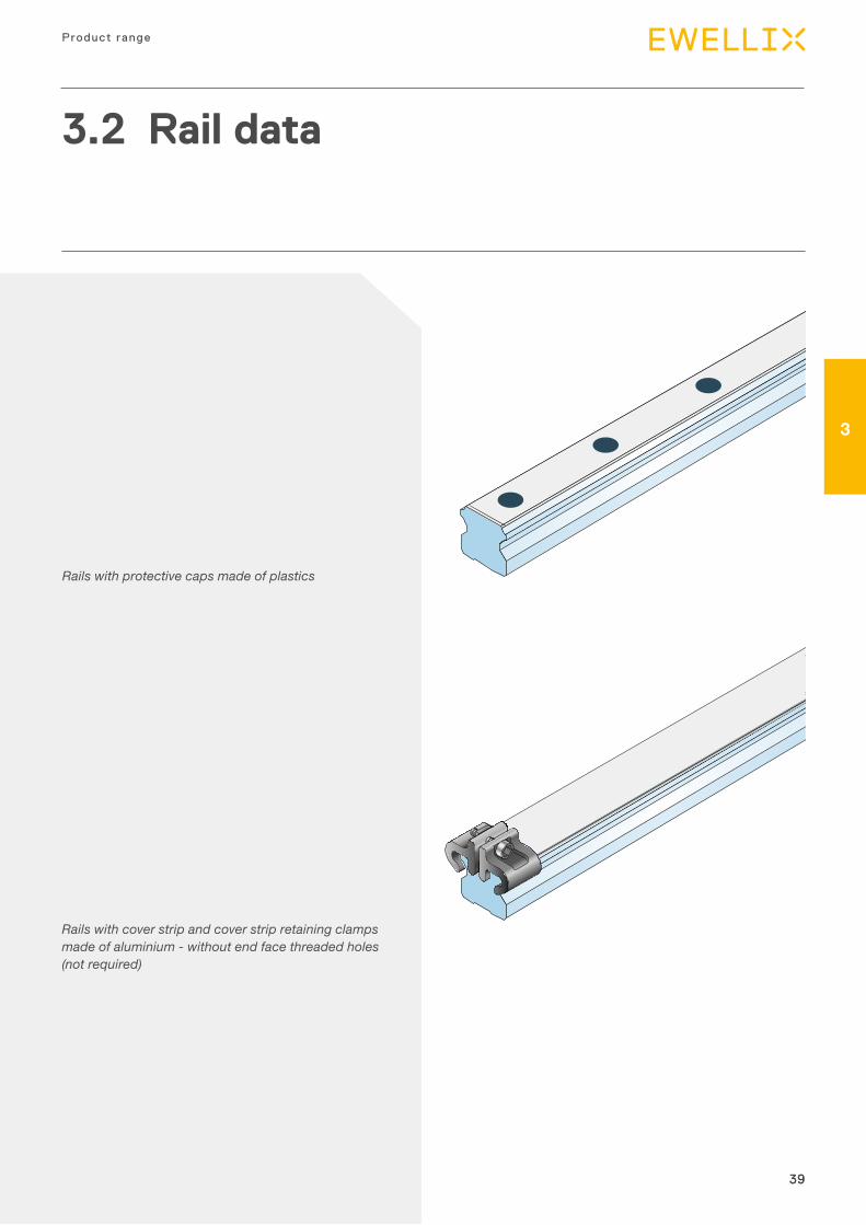
3.2 Rail data
Rails with cover strip and cover strip retaining clamps made of aluminium - without end face threaded holes (not required)
Rails with protective caps made of plastics
40
Prof i le ra i l gu ides - LLR
40
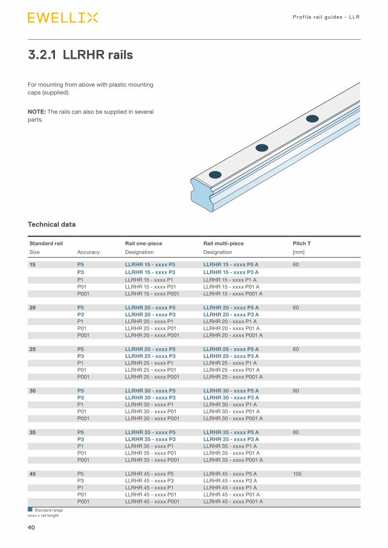
3.2.1 LLRHR rails
For mounting from above with plastic mounting caps (supplied).
NOTE: The rails can also be supplied in several parts.
Technical data
Standard rail Rail one-piece Rail multi-piece Pitch TSize Accuracy Designation Designation [mm]
15 P5 LLRHR 15 - xxxx P5 LLRHR 15 - xxxx P5 A 60P3 LLRHR 15 - xxxx P3 LLRHR 15 - xxxx P3 AP1 LLRHR 15 - xxxx P1 LLRHR 15 - xxxx P1 AP01 LLRHR 15 - xxxx P01 LLRHR 15 - xxxx P01 AP001 LLRHR 15 - xxxx P001 LLRHR 15 - xxxx P001 A
20 P5 LLRHR 20 - xxxx P5 LLRHR 20 - xxxx P5 A 60P3 LLRHR 20 - xxxx P3 LLRHR 20 - xxxx P3 AP1 LLRHR 20 - xxxx P1 LLRHR 20 - xxxx P1 AP01 LLRHR 20 - xxxx P01 LLRHR 20 - xxxx P01 AP001 LLRHR 20 - xxxx P001 LLRHR 20 - xxxx P001 A
25 P5 LLRHR 25 - xxxx P5 LLRHR 25 - xxxx P5 A 60P3 LLRHR 25 - xxxx P3 LLRHR 25 - xxxx P3 AP1 LLRHR 25 - xxxx P1 LLRHR 25 - xxxx P1 AP01 LLRHR 25 - xxxx P01 LLRHR 25 - xxxx P01 AP001 LLRHR 25 - xxxx P001 LLRHR 25 - xxxx P001 A
30 P5 LLRHR 30 - xxxx P5 LLRHR 30 - xxxx P5 A 80P3 LLRHR 30 - xxxx P3 LLRHR 30 - xxxx P3 AP1 LLRHR 30 - xxxx P1 LLRHR 30 - xxxx P1 AP01 LLRHR 30 - xxxx P01 LLRHR 30 - xxxx P01 AP001 LLRHR 30 - xxxx P001 LLRHR 30 - xxxx P001 A
35 P5 LLRHR 35 - xxxx P5 LLRHR 35 - xxxx P5 A 80P3 LLRHR 35 - xxxx P3 LLRHR 35 - xxxx P3 AP1 LLRHR 35 - xxxx P1 LLRHR 35 - xxxx P1 AP01 LLRHR 35 - xxxx P01 LLRHR 35 - xxxx P01 AP001 LLRHR 35 - xxxx P001 LLRHR 35 - xxxx P001 A
45 P5 LLRHR 45 - xxxx P5 LLRHR 45 - xxxx P5 A 105P3 LLRHR 45 - xxxx P3 LLRHR 45 - xxxx P3 AP1 LLRHR 45 - xxxx P1 LLRHR 45 - xxxx P1 AP01 LLRHR 45 - xxxx P01 LLRHR 45 - xxxx P01 AP001 LLRHR 45 - xxxx P001 LLRHR 45 - xxxx P001 A
Standard range xxxx = rail length
41
3
41
Product range
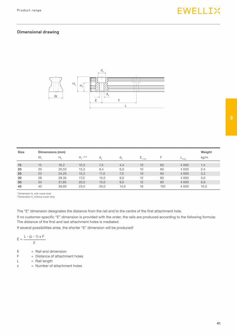
Dimensional drawing
d2
d3WE F
L
H4 H7
Size Dimensions (mm) WeightW1 H4 H7 ±0,5 d2 d3 E1 min F Lmax kg/m
15 15 16,2 10,3 7,4 4,4 10 60 4 000 1,420 20 20,55 13,2 9,4 6,0 10 60 4 000 2,425 23 24,25 15,2 11,0 7,0 10 60 4 000 3,230 28 28,35 17,0 15,0 9,0 12 80 4 000 5,035 34 31,85 20,5 15,0 9,0 12 80 4 000 6,845 45 39,85 23,5 20,0 14,0 16 105 4 000 10,5
1) Dimension H4 with cover strip2) Dimension H4 without cover strip
The “E” dimension designates the distance from the rail end to the centre of the first attachment hole.If no customer-specific “E” dimension is provided with the order, the rails are produced according to the following formula: The distance of the first and last attachment holes is mediated.If several possibilities arise, the shorter “E” dimension will be produced!
E = Rail end dimension F = Distance of attachment holes L = Rail length z = Number of attachment holes
E = L - (z - 1) x F
2
42
Prof i le ra i l gu ides - LLR
42
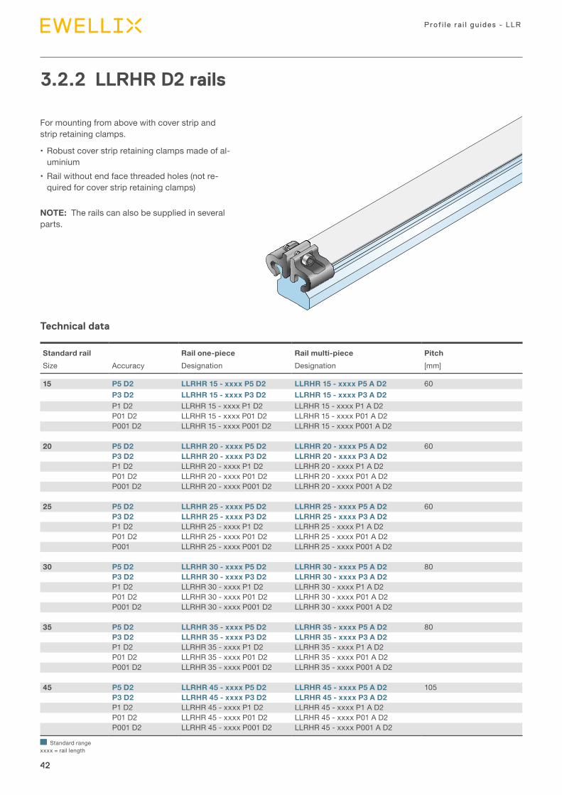
3.2.2 LLRHR D2 rails
For mounting from above with cover strip and strip retaining clamps.
• Robust cover strip retaining clamps made of al-uminium
• Rail without end face threaded holes (not re-quired for cover strip retaining clamps)
NOTE: The rails can also be supplied in several parts.
Technical data
Standard rail Rail one-piece Rail multi-piece PitchSize Accuracy Designation Designation [mm]
15 P5 D2 LLRHR 15 - xxxx P5 D2 LLRHR 15 - xxxx P5 A D2 60P3 D2 LLRHR 15 - xxxx P3 D2 LLRHR 15 - xxxx P3 A D2P1 D2 LLRHR 15 - xxxx P1 D2 LLRHR 15 - xxxx P1 A D2P01 D2 LLRHR 15 - xxxx P01 D2 LLRHR 15 - xxxx P01 A D2P001 D2 LLRHR 15 - xxxx P001 D2 LLRHR 15 - xxxx P001 A D2
20 P5 D2 LLRHR 20 - xxxx P5 D2 LLRHR 20 - xxxx P5 A D2 60P3 D2 LLRHR 20 - xxxx P3 D2 LLRHR 20 - xxxx P3 A D2P1 D2 LLRHR 20 - xxxx P1 D2 LLRHR 20 - xxxx P1 A D2P01 D2 LLRHR 20 - xxxx P01 D2 LLRHR 20 - xxxx P01 A D2P001 D2 LLRHR 20 - xxxx P001 D2 LLRHR 20 - xxxx P001 A D2
25 P5 D2 LLRHR 25 - xxxx P5 D2 LLRHR 25 - xxxx P5 A D2 60P3 D2 LLRHR 25 - xxxx P3 D2 LLRHR 25 - xxxx P3 A D2P1 D2 LLRHR 25 - xxxx P1 D2 LLRHR 25 - xxxx P1 A D2P01 D2 LLRHR 25 - xxxx P01 D2 LLRHR 25 - xxxx P01 A D2P001 LLRHR 25 - xxxx P001 D2 LLRHR 25 - xxxx P001 A D2
30 P5 D2 LLRHR 30 - xxxx P5 D2 LLRHR 30 - xxxx P5 A D2 80P3 D2 LLRHR 30 - xxxx P3 D2 LLRHR 30 - xxxx P3 A D2P1 D2 LLRHR 30 - xxxx P1 D2 LLRHR 30 - xxxx P1 A D2P01 D2 LLRHR 30 - xxxx P01 D2 LLRHR 30 - xxxx P01 A D2P001 D2 LLRHR 30 - xxxx P001 D2 LLRHR 30 - xxxx P001 A D2
35 P5 D2 LLRHR 35 - xxxx P5 D2 LLRHR 35 - xxxx P5 A D2 80P3 D2 LLRHR 35 - xxxx P3 D2 LLRHR 35 - xxxx P3 A D2P1 D2 LLRHR 35 - xxxx P1 D2 LLRHR 35 - xxxx P1 A D2P01 D2 LLRHR 35 - xxxx P01 D2 LLRHR 35 - xxxx P01 A D2P001 D2 LLRHR 35 - xxxx P001 D2 LLRHR 35 - xxxx P001 A D2
45 P5 D2 LLRHR 45 - xxxx P5 D2 LLRHR 45 - xxxx P5 A D2 105P3 D2 LLRHR 45 - xxxx P3 D2 LLRHR 45 - xxxx P3 A D2P1 D2 LLRHR 45 - xxxx P1 D2 LLRHR 45 - xxxx P1 A D2P01 D2 LLRHR 45 - xxxx P01 D2 LLRHR 45 - xxxx P01 A D2P001 D2 LLRHR 45 - xxxx P001 D2 LLRHR 45 - xxxx P001 A D2
Standard range xxxx = rail length
43
3
43
Product range
Dimensional drawing
d2
d3
H4 H7
H6
E F
WL7
L8
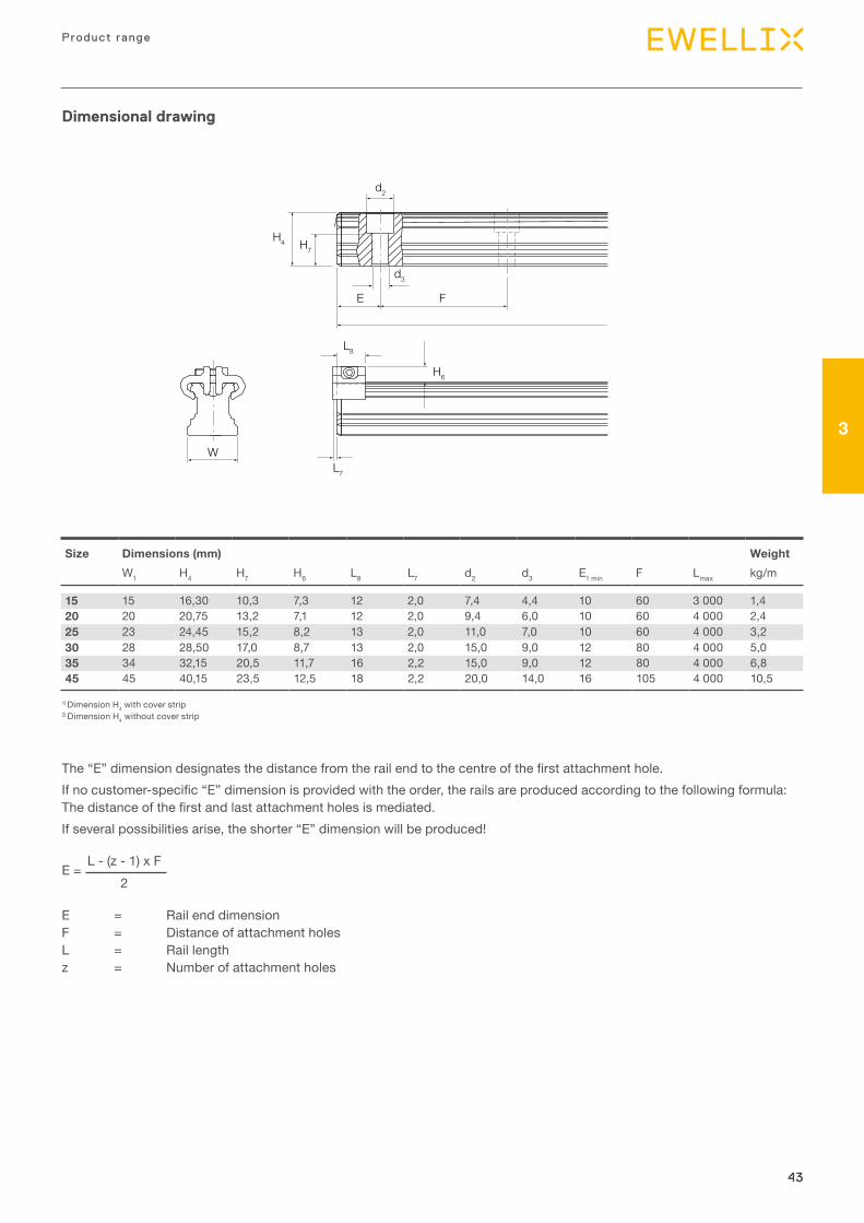
Size Dimensions (mm) WeightW1 H4 H7 H6 L8 L7 d2 d3 E1 min F Lmax kg/m
15 15 16,30 10,3 7,3 12 2,0 7,4 4,4 10 60 3 000 1,420 20 20,75 13,2 7,1 12 2,0 9,4 6,0 10 60 4 000 2,425 23 24,45 15,2 8,2 13 2,0 11,0 7,0 10 60 4 000 3,230 28 28,50 17,0 8,7 13 2,0 15,0 9,0 12 80 4 000 5,035 34 32,15 20,5 11,7 16 2,2 15,0 9,0 12 80 4 000 6,845 45 40,15 23,5 12,5 18 2,2 20,0 14,0 16 105 4 000 10,5
1) Dimension H4 with cover strip2) Dimension H4 without cover strip
The “E” dimension designates the distance from the rail end to the centre of the first attachment hole.If no customer-specific “E” dimension is provided with the order, the rails are produced according to the following formula: The distance of the first and last attachment holes is mediated.If several possibilities arise, the shorter “E” dimension will be produced!
E = Rail end dimension F = Distance of attachment holes L = Rail length z = Number of attachment holes
E = L - (z - 1) x F
2

45
3
45
Product range
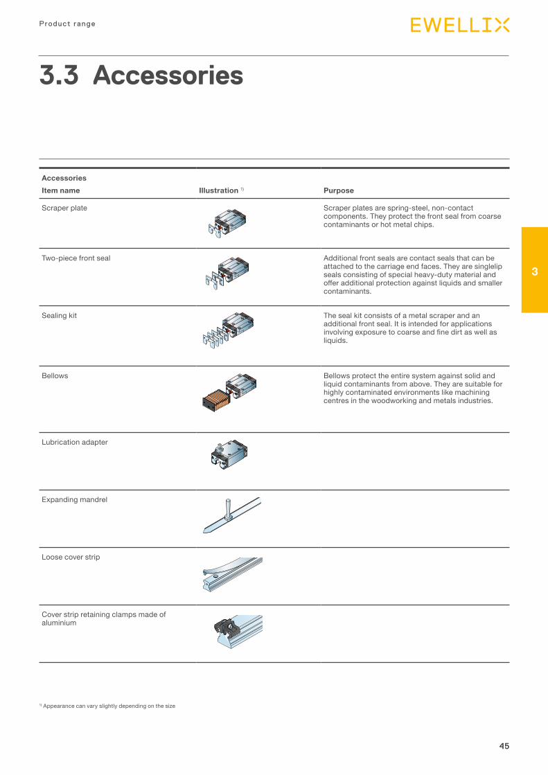
AccessoriesItem name Illustration 1) Purpose
Scraper plate Scraper plates are spring-steel, non-contact components. They protect the front seal from coarse contaminants or hot metal chips.
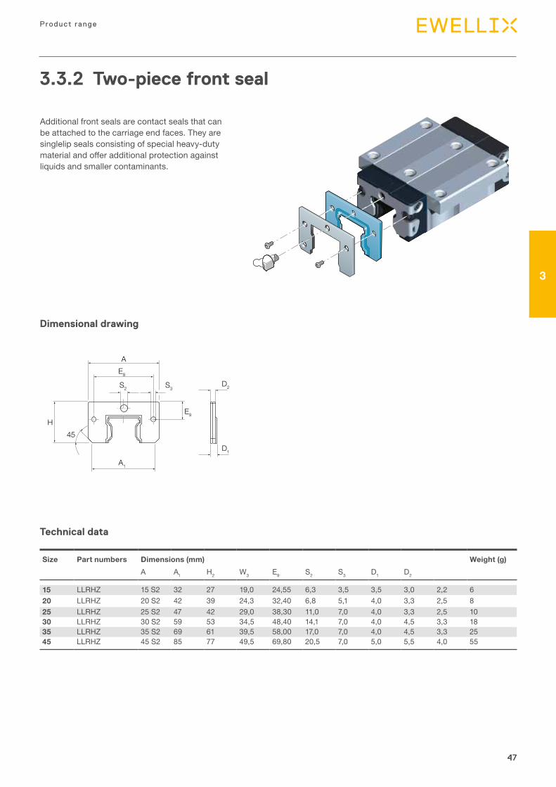
Two-piece front seal Additional front seals are contact seals that can be attached to the carriage end faces. They are singlelip seals consisting of special heavy-duty material and offer additional protection against liquids and smaller contaminants.
Sealing kit The seal kit consists of a metal scraper and an additional front seal. It is intended for applications involving exposure to coarse and fine dirt as well as liquids.
Bellows Bellows protect the entire system against solid and liquid contaminants from above. They are suitable for highly contaminated environments like machining centres in the woodworking and metals industries.
Lubrication adapter
Expanding mandrel
Loose cover strip
Cover strip retaining clamps made of aluminium
3.3 Accessories
1) Appearance can vary slightly depending on the size
46
Prof i le ra i l gu ides - LLR
46
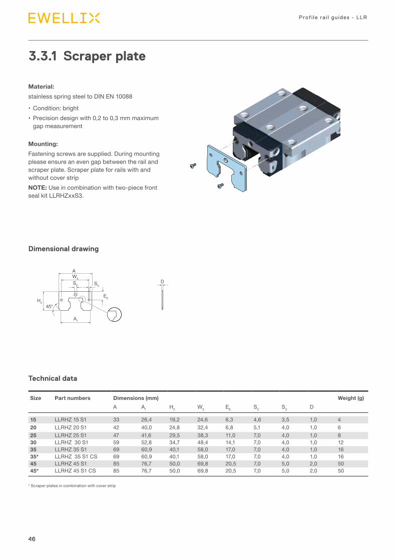
3.3.1 Scraper plate
Material: stainless spring steel to DIN EN 10088
• Condition: bright• Precision design with 0,2 to 0,3 mm maximum
gap measurement
Mounting: Fastening screws are supplied. During mounting please ensure an even gap between the rail and scraper plate. Scraper plate for rails with and without cover stripNOTE: Use in combination with two-piece front seal kit LLRHZxxS3.
Technical data
Dimensional drawing
Size Part numbers Dimensions (mm) Weight (g)A A1 H2 W3 E9 S2 S3 D
15 LLRHZ 15 S1 33 26,4 19,2 24,6 6,3 4,6 3,5 1,0 420 LLRHZ 20 S1 42 40,0 24,8 32,4 6,8 5,1 4,0 1,0 625 LLRHZ 25 S1 47 41,6 29,5 38,3 11,0 7,0 4,0 1,0 830 LLRHZ 30 S1 59 52,8 34,7 48,4 14,1 7,0 4,0 1,0 1235 LLRHZ 35 S1 69 60,9 40,1 58,0 17,0 7,0 4,0 1,0 1635* LLRHZ 35 S1 CS 69 60,9 40,1 58,0 17,0 7,0 4,0 1,0 1645 LLRHZ 45 S1 85 76,7 50,0 69,8 20,5 7,0 5,0 2,0 5045* LLRHZ 45 S1 CS 85 76,7 50,0 69,8 20,5 7,0 5,0 2,0 50
* Scraper plates in combination with cover strip
H2
A
A1
W3
S2 S3D
E9
45°
47
3
47
Product range
Additional front seals are contact seals that can be attached to the carriage end faces. They are singlelip seals consisting of special heavy-duty material and offer additional protection against liquids and smaller contaminants.
3.3.2 Two-piece front seal
45
Two-piece front seal
Seal kitThe seal kit consists of the followingcomponents:1 Scraper plate2 Support plate3 Two-piece front seal
Size Part numbers Dimensions (mm) Weight (g)A A1 H2 W3 E9 S2 S3 D1 D2
15 LLRHZ 15 S2 32 27 19,0 24,55 6,3 3,5 3,5 3,0 2,2 620 LLRHZ 20 S2 42 39 24,3 32,4 6,8 5,1 4 3,3 2,5 825 LLRHZ 25 S2 47 42 29,0 38,3 11,0 7 4 3,3 2,5 1030 LLRHZ 30 S2 59 53 34,5 48,4 14,1 7 4 4,5 3,3 1835 LLRHZ 35 S2 69 61 39,5 58,0 17,0 7 4 4,5 3,3 2545 LLRHZ 45 S2 85 77 49,5 69,8 20,5 7 5 5,5 4,0 55
Size Seal kitDesignation
15 LLRHZ 15 S320 LLRHZ 20 S325 LLRHZ 25 S330 LLRHZ 30 S335 LLRHZ 35 S335 CS* LLRHZ 35 S3 CS45 LLRHZ 45 S345 CS* LLRHZ 45 S3 CS
*Seal kit in combination with cover strip
Technical data
Dimensional drawing
Size Part numbers Dimensions (mm) Weight (g)A A1 H2 W3 E9 S2 S3 D1 D2
15 LLRHZ 15 S2 32 27 19,0 24,55 6,3 3,5 3,5 3,0 2,2 620 LLRHZ 20 S2 42 39 24,3 32,40 6,8 5,1 4,0 3,3 2,5 825 LLRHZ 25 S2 47 42 29,0 38,30 11,0 7,0 4,0 3,3 2,5 1030 LLRHZ 30 S2 59 53 34,5 48,40 14,1 7,0 4,0 4,5 3,3 1835 LLRHZ 35 S2 69 61 39,5 58,00 17,0 7,0 4,0 4,5 3,3 2545 LLRHZ 45 S2 85 77 49,5 69,80 20,5 7,0 5,0 5,5 4,0 55
A
A1
E8
S3S2
E9
D2
D1
45H
48
Prof i le ra i l gu ides - LLR
48
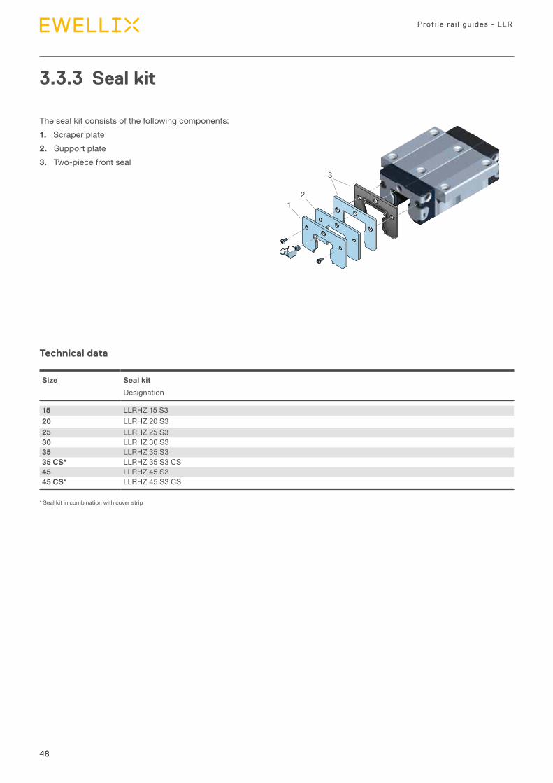
3.3.3 Seal kit
The seal kit consists of the following components:1. Scraper plate2. Support plate3. Two-piece front seal
12
3
Technical data
Size Seal kitDesignation
15 LLRHZ 15 S320 LLRHZ 20 S325 LLRHZ 25 S330 LLRHZ 30 S335 LLRHZ 35 S335 CS* LLRHZ 35 S3 CS45 LLRHZ 45 S345 CS* LLRHZ 45 S3 CS
* Seal kit in combination with cover strip
49
3
49
Product range
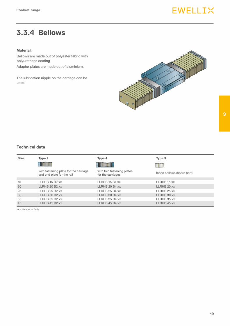
3.3.4 Bellows
Material: Bellows are made out of polyester fabric with polyurethane coatingAdapter plates are made out of aluminium.
The lubrication nipple on the carriage can be used.
Technical data
Size Type 2 Type 4 Type 9
with fastening plate for the carriage and end plate for the rail
with two fastening plates for the carriages loose bellows (spare part)
15 LLRHB 15 B2 xx LLRHB 15 B4 xx LLRHB 15 xx20 LLRHB 20 B2 xx LLRHB 20 B4 xx LLRHB 20 xx25 LLRHB 25 B2 xx LLRHB 25 B4 xx LLRHB 25 xx30 LLRHB 30 B2 xx LLRHB 30 B4 xx LLRHB 30 xx35 LLRHB 35 B2 xx LLRHB 35 B4 xx LLRHB 35 xx45 LLRHB 45 B2 xx LLRHB 45 B4 xx LLRHB 45 xx
xx = Number of folds
50
Prof i le ra i l gu ides - LLR
50
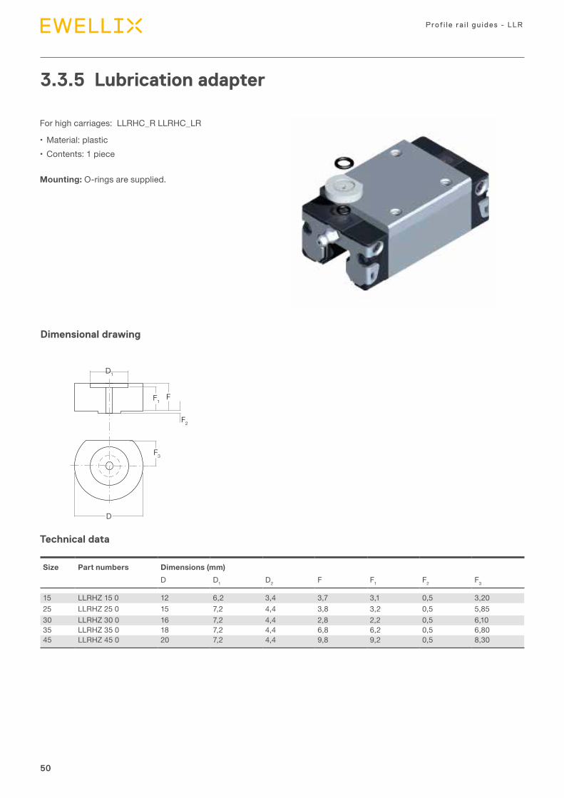
3.3.5 Lubrication adapter
For high carriages: LLRHC_R LLRHC_LR
• Material: plastic• Contents: 1 piece
Mounting: O-rings are supplied.
Technical data
Dimensional drawing
F3
F2
D
F
D1
F1
Size Part numbers Dimensions (mm) D D1 D2 F F1 F2 F3
15 LLRHZ 15 0 12 6,2 3,4 3,7 3,1 0,5 3,2025 LLRHZ 25 0 15 7,2 4,4 3,8 3,2 0,5 5,8530 LLRHZ 30 0 16 7,2 4,4 2,8 2,2 0,5 6,1035 LLRHZ 35 0 18 7,2 4,4 6,8 6,2 0,5 6,8045 LLRHZ 45 0 20 7,2 4,4 9,8 9,2 0,5 8,30
51
3
51
Product range
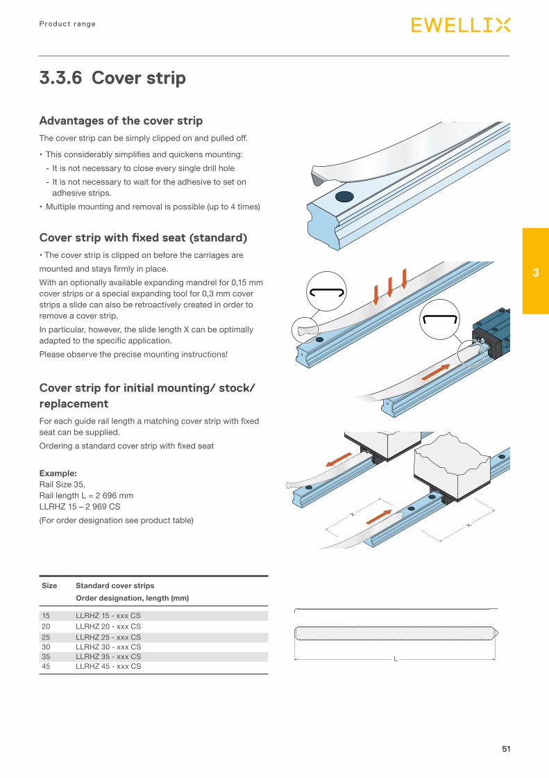
3.3.6 Cover strip
Advantages of the cover stripThe cover strip can be simply clipped on and pulled off.
• This considerably simplifies and quickens mounting: - It is not necessary to close every single drill hole - It is not necessary to wait for the adhesive to set on adhesive strips.
• Multiple mounting and removal is possible (up to 4 times)
Cover strip with fixed seat (standard)• The cover strip is clipped on before the carriages aremounted and stays firmly in place.With an optionally available expanding mandrel for 0,15 mm cover strips or a special expanding tool for 0,3 mm cover strips a slide can also be retroactively created in order to remove a cover strip.In particular, however, the slide length X can be optimally adapted to the specific application.Please observe the precise mounting instructions!
Cover strip for initial mounting/ stock/replacementFor each guide rail length a matching cover strip with fixed seat can be supplied.Ordering a standard cover strip with fixed seat
Example: Rail Size 35, Rail length L = 2 696 mm LLRHZ 15 – 2 969 CS(For order designation see product table)
X
X
L
Size Standard cover stripsOrder designation, length (mm)
15 LLRHZ 15 - xxx CS20 LLRHZ 20 - xxx CS25 LLRHZ 25 - xxx CS30 LLRHZ 30 - xxx CS35 LLRHZ 35 - xxx CS45 LLRHZ 45 - xxx CS
52
Prof i le ra i l gu ides - LLR
52
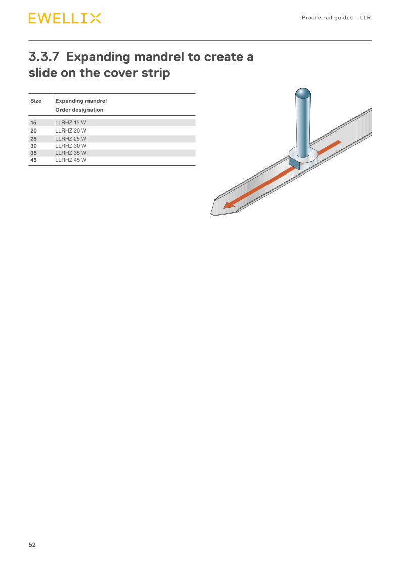
3.3.7 Expanding mandrel to create a slide on the cover strip
Size Expanding mandrelOrder designation
15 LLRHZ 15 W20 LLRHZ 20 W25 LLRHZ 25 W30 LLRHZ 30 W35 LLRHZ 35 W45 LLRHZ 45 W
53
3
53
Product range
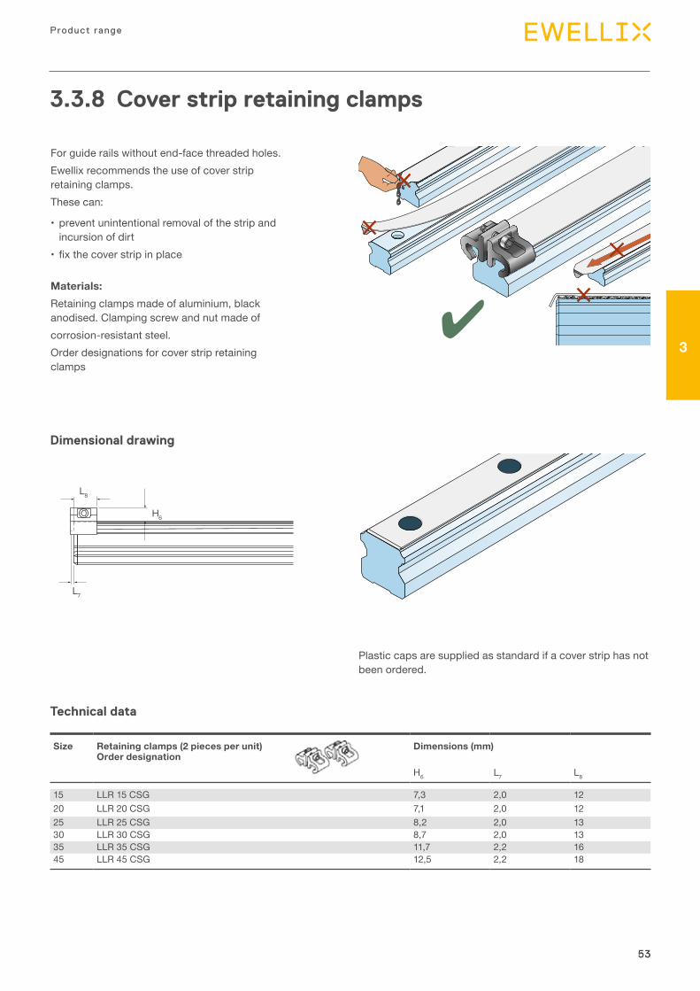
3.3.8 Cover strip retaining clamps
L7
L8
H6
Technical data
Dimensional drawing
Size Retaining clamps (2 pieces per unit) Order designation
Dimensions (mm)
H6 L7 L8
15 LLR 15 CSG 7,3 2,0 1220 LLR 20 CSG 7,1 2,0 1225 LLR 25 CSG 8,2 2,0 1330 LLR 30 CSG 8,7 2,0 1335 LLR 35 CSG 11,7 2,2 1645 LLR 45 CSG 12,5 2,2 18
For guide rails without end-face threaded holes.Ewellix recommends the use of cover strip retaining clamps.These can:
• prevent unintentional removal of the strip and incursion of dirt
• fix the cover strip in place
Materials:Retaining clamps made of aluminium, black anodised. Clamping screw and nut made ofcorrosion-resistant steel.Order designations for cover strip retaining clamps
Plastic caps are supplied as standard if a cover strip has not been ordered.
IntroductionLorem ipsum
Mounting instruction and maintenance
4
55
Mounting instruction and maintenance
4
4.1 Design rules
4.1.1 General instructionsThe following mounting instructions apply to all profile rail guides.Please note, however, that differ-ing specifications exist concerning the parallelism of the rails as well as the screwing and pinning of the car-riages. These are therefore assigned to the individual versions.Ball profile rail guides. are high-quality products. Greatest possible care should be taken during trans-port and subsequent assembly. All steel parts have been oil-protected. The protection materials do not need to be removed if the recom-mended lubricants are used. Detailed mounting instructions are available through your normal Ewellix contact.
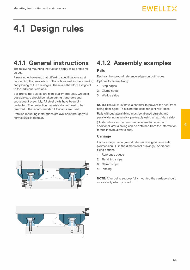
4.1.2 Assembly examplesRails
Each rail has ground reference edges on both sides.Options for lateral fixing:1. Stop edges 2. Clamp strips3. Wedge strips
NOTE: The rail must have a chamfer to prevent the seal from being dam-aged. This is not the case for joint rail tracksRails without lateral fixing must be aligned straight and parallel during assembly, preferably using an auxil-iary strip.(Guide values for the permissible lateral force without additional later-al fixing can be obtained from the information for the individual ver-sions).
Carriage
Each carriage has a ground refer-ence edge on one side (<dimension H3 in the dimensional drawings). Additional fixing options:1. Reference edges2. Retaining strips3. Clamp strips4. Pinning
NOTE: After being successfully mounted the carriage should move easily when pushed.
21
4
1
3
56
Prof i le ra i l gu ides - LLR
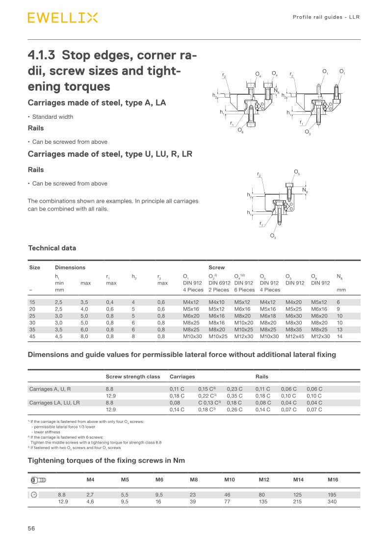
4.1.3 Stop edges, corner ra-dii, screw sizes and tight-ening torquesCarriages made of steel, type A, LA
• Standard width
Rails
• Can be screwed from above
Carriages made of steel, type U, LU, R, LR
Rails
• Can be screwed from above
The combinations shown are examples. In principle all carriages can be combined with all rails.
Tightening torques of the fixing screws in Nm
Dimensions and guide values for permissible lateral force without additional lateral fixing
Size Dimensions Screwh1 r1 h2 r2 O1 O2
2) O41)2) O5 O3 O6 N8
min max max max DIN 912 DIN 6912 DIN 912 DIN 912 DIN 912 DIN 912– mm 4 Pieces 2 Pieces 6 Pieces 4 Pieces mm
15 2,5 3,5 0,4 4 0,6 M4x12 M4x10 M5x12 M4x12 M4x20 M5x12 620 2,5 4,0 0,6 5 0,6 M5x16 M5x12 M6x16 M5x16 M5x25 M6x16 925 3,0 5,0 0,8 5 0,8 M6x20 M6x16 M8x20 M6x18 M6x30 M6x20 1030 3,0 5,0 0,8 6 0,8 M8x25 M8x16 M10x20 M8x20 M8x30 M8x20 1035 3,5 6,0 0,8 6 0,8 M8x25 M8x20 M10x25 M8x25 M8x35 M8x25 1345 4,5 8,0 0,8 8 0,8 M10x30 M10x25 M12x30 M10x30 M12x45 M12x30 14
Screw strength class Carriages Rails
Carriages A, U, R 8.8 0,11 C 0,15 C3) 0,23 C 0,11 C 0,06 C 0,06 C12.9 0,18 C 0,22 C3) 0,35 C 0,18 C 0,10 C 0,10 C
Carriages LA, LU, LR 8.8 0,08 C 0,13 C3) 0,18 C 0,08 C 0,04 C 0,04 C12.9 0,14 C 0,18 C3) 0,26 C 0,14 C 0,07 C 0,07 C
M4 M5 M6 M8 M10 M12 M14 M16
8.8 2,7 5,5 9,5 23 46 80 125 19512.9 4,6 9,5 16 39 77 135 215 340
1) If the carriage is fastened from above with only four O4 screws:- permissible lateral force 1/3 lower- lower stiffness
2) If the carriage is fastened with 6 screws: Tighten the middle screws with a tightening torque for strength class 8.8
3) If fastened with two O2 screws and four O1 screws
Technical data
O4r2
h2 h2
h1
r1O6
N8
r2O4
O3
r1
h1
O1 O1
N8
r2O5
O3
r1
h2
h1
57
Mounting instruction and maintenance
4
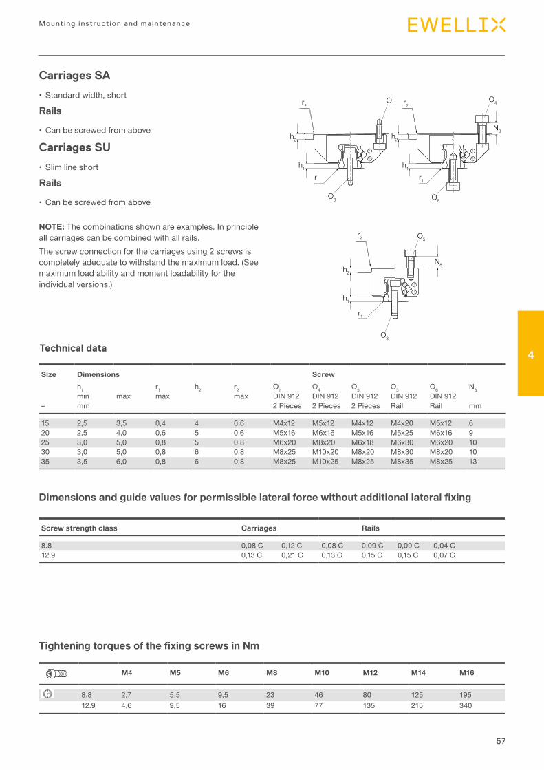
Carriages SA
• Standard width, short
Rails
• Can be screwed from above
Carriages SU
• Slim line short
Rails
• Can be screwed from above
NOTE: The combinations shown are examples. In principle all carriages can be combined with all rails.The screw connection for the carriages using 2 screws is completely adequate to withstand the maximum load. (See maximum load ability and moment loadability for the individual versions.)
Tightening torques of the fixing screws in Nm
Dimensions and guide values for permissible lateral force without additional lateral fixing
Size Dimensions Screwh1 r1 h2 r2 O1 O4 O5 O3 O6 N8min max max max DIN 912 DIN 912 DIN 912 DIN 912 DIN 912
– mm 2 Pieces 2 Pieces 2 Pieces Rail Rail mm
15 2,5 3,5 0,4 4 0,6 M4x12 M5x12 M4x12 M4x20 M5x12 620 2,5 4,0 0,6 5 0,6 M5x16 M6x16 M5x16 M5x25 M6x16 925 3,0 5,0 0,8 5 0,8 M6x20 M8x20 M6x18 M6x30 M6x20 1030 3,0 5,0 0,8 6 0,8 M8x25 M10x20 M8x20 M8x30 M8x20 1035 3,5 6,0 0,8 6 0,8 M8x25 M10x25 M8x25 M8x35 M8x25 13
Screw strength class Carriages Rails
8.8 0,08 C 0,12 C 0,08 C 0,09 C 0,09 C 0,04 C12.9 0,13 C 0,21 C 0,13 C 0,15 C 0,15 C 0,07 C
M4 M5 M6 M8 M10 M12 M14 M16
8.8 2,7 5,5 9,5 23 46 80 125 19512.9 4,6 9,5 16 39 77 135 215 340
Technical data
r2 r2
h2
h1
h2
h1
r1 r1
O3 O6
O4
N8
O1
O5
O3
N8
r1
r2
h2
h1
58
Prof i le ra i l gu ides - LLR
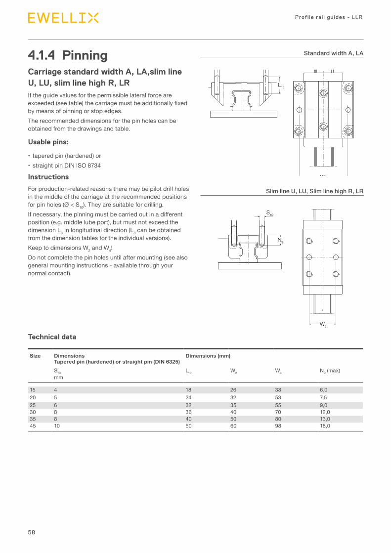
4.1.4 PinningCarriage standard width A, LA,slim line U, LU, slim line high R, LRIf the guide values for the permissible lateral force are exceeded (see table) the carriage must be additionally fixed by means of pinning or stop edges.The recommended dimensions for the pin holes can be obtained from the drawings and table.
Usable pins:
• tapered pin (hardened) or• straight pin DIN ISO 8734
Instructions
For production-related reasons there may be pilot drill holes in the middle of the carriage at the recommended positions for pin holes (Ø < S10). They are suitable for drilling.If necessary, the pinning must be carried out in a different position (e.g. middle lube port), but must not exceed the dimension L3 in longitudinal direction (L3 can be obtained from the dimension tables for the individual versions).Keep to dimensions W2 and W4!Do not complete the pin holes until after mounting (see also general mounting instructions - available through your normal contact).
Technical data
Size Dimensions Tapered pin (hardened) or straight pin (DIN 6325)
Dimensions (mm)
S10 L10 W2 W4 N9 (max)mm
15 4 18 26 38 6,020 5 24 32 53 7,525 6 32 35 55 9,030 8 36 40 70 12,035 8 40 50 80 13,045 10 50 60 98 18,0
Standard width A, LA
Slim line U, LU, Slim line high R, LRStandard width A, LA
S10
L10
W4
S10
N9
W2
Slim line U, LUSlim line high R, LR
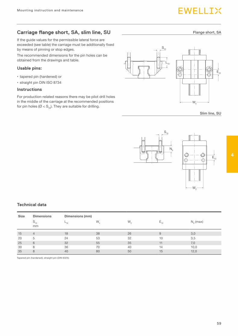
59
Mounting instruction and maintenance
4
Carriage flange short, SA, slim line, SUIf the guide values for the permissible lateral force are exceeded (see table) the carriage must be additionally fixed by means of pinning or stop edges.The recommended dimensions for the pin holes can be obtained from the drawings and table.
Usable pins:
• tapered pin (hardened) or• straight pin DIN ISO 8734
Instructions
For production-related reasons there may be pilot drill holes in the middle of the carriage at the recommended positions for pin holes (Ø < S10). They are suitable for drilling.
Technical data
Size Dimensions Dimensions (mm) S10 L10 W4 W2 E10 N9 (max)mm
15 4 18 38 26 9 3,020 5 24 53 32 10 3,525 6 32 55 35 11 7,030 8 36 70 40 14 10,035 8 40 80 50 15 12,0
Flange short, SA
Slim line, SU
Tapered pin (hardened), straight pin (DIN 6325)
Flange short, SA
S10
L10
E10
W4
Slim line, SU
S10
E10
W2
N9
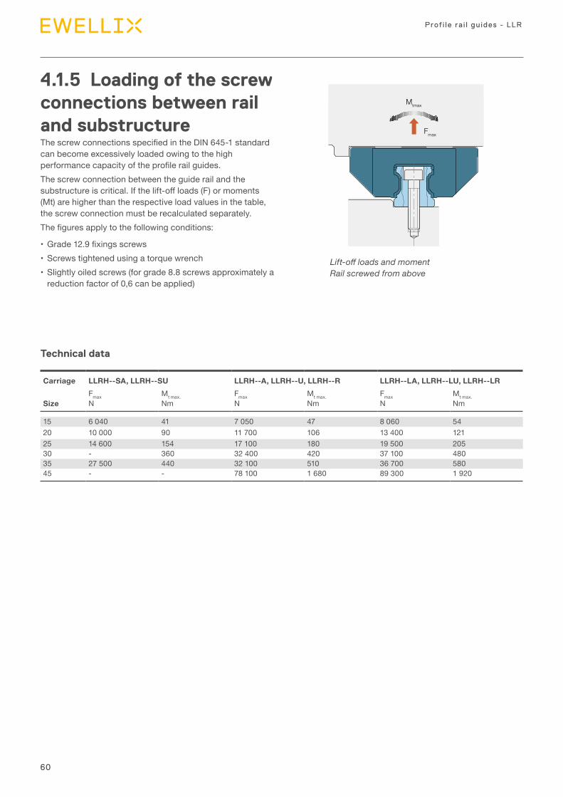
60
Prof i le ra i l gu ides - LLR
Mtmax
Fmax
4.1.5 Loading of the screw connections between rail and substructureThe screw connections specified in the DIN 645-1 standard can become excessively loaded owing to the high performance capacity of the profile rail guides.The screw connection between the guide rail and the substructure is critical. If the lift-off loads (F) or moments (Mt) are higher than the respective load values in the table, the screw connection must be recalculated separately.The figures apply to the following conditions:
• Grade 12.9 fixings screws• Screws tightened using a torque wrench• Slightly oiled screws (for grade 8.8 screws approximately a
reduction factor of 0,6 can be applied)
Technical data
Carriage LLRH--SA, LLRH--SU LLRH--A, LLRH--U, LLRH--R LLRH--LA, LLRH--LU, LLRH--LRFmax Mt max. Fmax Mt max. Fmax Mt max.
Size N Nm N Nm N Nm
15 6 040 41 7 050 47 8 060 5420 10 000 90 11 700 106 13 400 12125 14 600 154 17 100 180 19 500 20530 - 360 32 400 420 37 100 48035 27 500 440 32 100 510 36 700 58045 - - 78 100 1 680 89 300 1 920
Lift-off loads and momentRail screwed from above
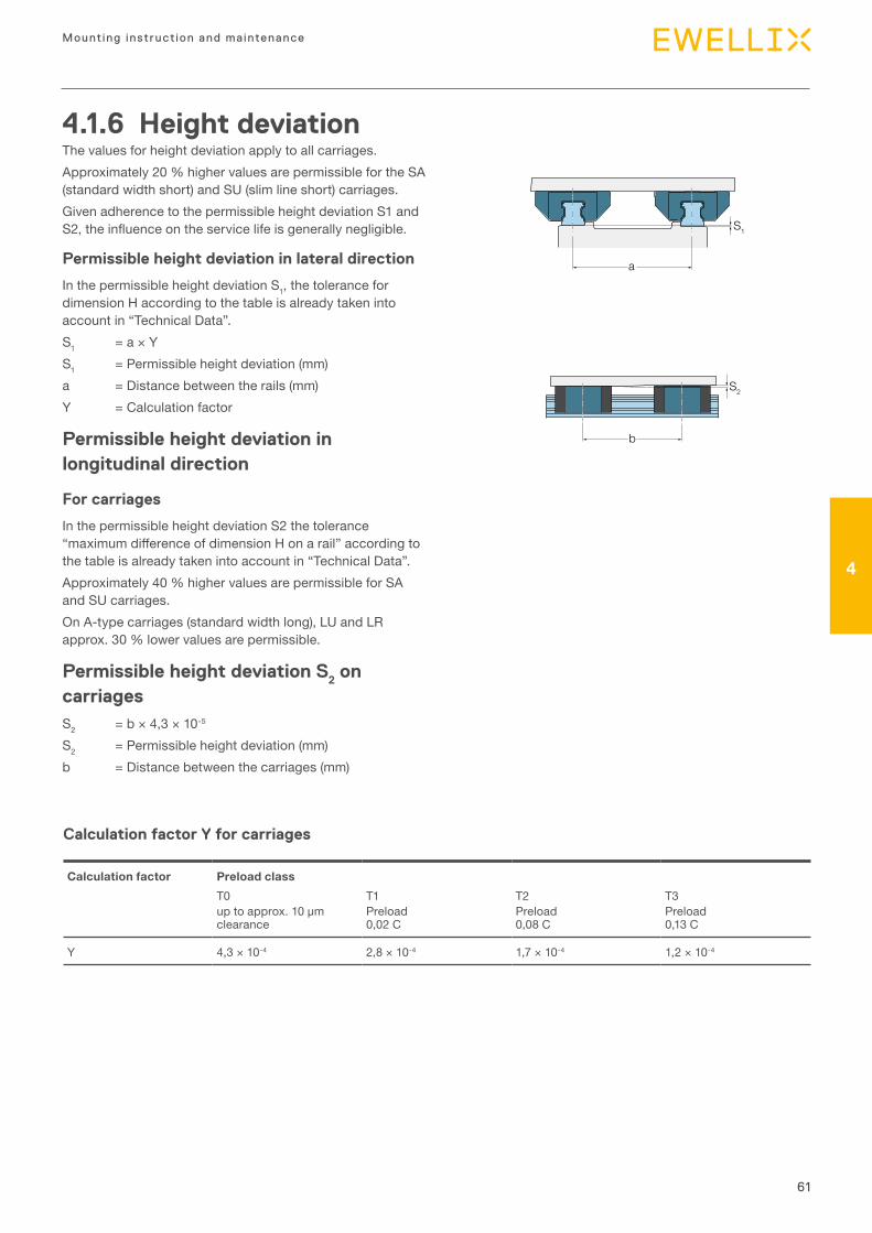
61
Mounting instruction and maintenance
4
Calculation factor Y for carriages
Calculation factor Preload classT0 T1 T2 T3up to approx. 10 μm clearance
Preload 0,02 C
Preload 0,08 C
Preload 0,13 C
Y 4,3 × 10⁻⁴ 2,8 × 10⁻⁴ 1,7 × 10⁻⁴ 1,2 × 10⁻⁴
4.1.6 Height deviationThe values for height deviation apply to all carriages.Approximately 20 % higher values are permissible for the SA (standard width short) and SU (slim line short) carriages.Given adherence to the permissible height deviation S1 and S2, the influence on the service life is generally negligible.
Permissible height deviation in lateral direction
In the permissible height deviation S1, the tolerance for dimension H according to the table is already taken into account in “Technical Data”.S1 = a × YS1 = Permissible height deviation (mm)a = Distance between the rails (mm)Y = Calculation factor
Permissible height deviation in longitudinal direction
For carriages
In the permissible height deviation S2 the tolerance “maximum difference of dimension H on a rail” according to the table is already taken into account in “Technical Data”.Approximately 40 % higher values are permissible for SA and SU carriages.On A-type carriages (standard width long), LU and LR approx. 30 % lower values are permissible.
Permissible height deviation S2 on
carriagesS2 = b × 4,3 × 10⁻⁵
S2 = Permissible height deviation (mm)b = Distance between the carriages (mm)
a
S1
S2
b
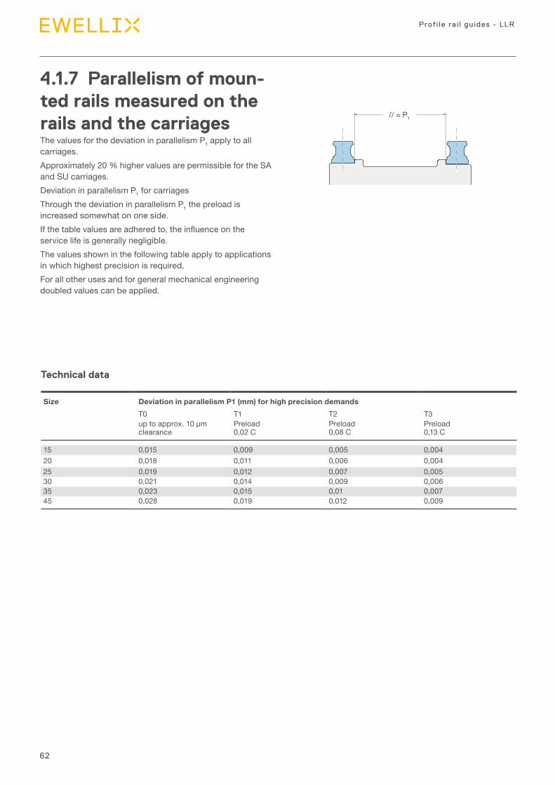
62
Prof i le ra i l gu ides - LLR
4.1.7 Parallelism of moun-ted rails measured on the rails and the carriagesThe values for the deviation in parallelism P1 apply to all carriages.Approximately 20 % higher values are permissible for the SA and SU carriages.Deviation in parallelism P1 for carriagesThrough the deviation in parallelism P1 the preload is increased somewhat on one side.If the table values are adhered to, the influence on the service life is generally negligible.The values shown in the following table apply to applications in which highest precision is required.For all other uses and for general mechanical engineering doubled values can be applied.
Technical data
Size Deviation in parallelism P1 (mm) for high precision demandsT0 T1 T2 T3up to approx. 10 μm clearance
Preload 0,02 C
Preload 0,08 C
Preload 0,13 C
15 0,015 0,009 0,005 0,00420 0,018 0,011 0,006 0,00425 0,019 0,012 0,007 0,00530 0,021 0,014 0,009 0,00635 0,023 0,015 0,01 0,00745 0,028 0,019 0,012 0,009
// = P1

63
Mounting instruction and maintenance
4
4.1.8 Mounting of lubrica-tion adapterA lubrication adapter is necessary on high carriages if lubrication is to take place from the table part.
In the recess for the O-ring seal a further small recess (1) has been preformed. Do not drill this open. Risk of dirt incursion!
• Heat up metal tip (2) with a diameter of 0,8 mm.• Carefully open the recess (1) with the metal tip and push
through. Observe maximum permissible depth Tmax stated in the ta-ble!
• Insert O-ring seal (3) in the recess.• Insert lubrication adapter at an angle in the recess and press the flattened side (4) onto the steel part (5). Use grease for fixing.
• Insert O-ring seal (6) in the lubrication adapter.
Size
Top lubrication opening: maximum permissible depth for penetration Tmax (mm)
Size Top lubrication opening: maximum permissible depth for penetration Tmax (mm)
15 3,620 3,925 3,330 6,635 7,545 8,8
Technical data
4
6
3
1
5
2
Ø 0,8
0,5
Tmax
5
M 3
1,6 8
M 6
Tmax
5
M 3
1,6 8
M 6
Dimensional drawing
DIN 3405, funnel-type nipplefor carriage size 15 and 20
DIN 71412, cone-type nipplefor carriage size 25, 30, 35 and 45
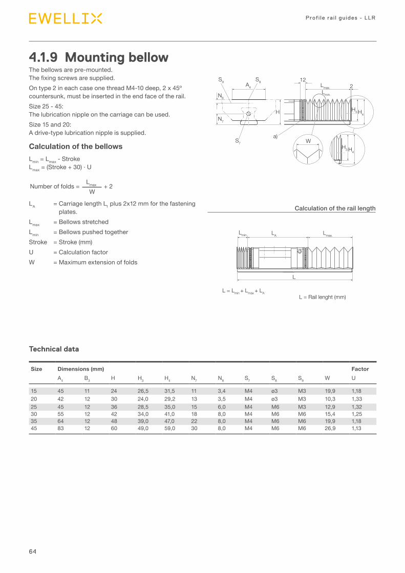
64
Prof i le ra i l gu ides - LLR
S9
S7
a)W
N8
N7
S9 122Lmax.
Lmax.
Lmin.
Lmin. LA
H3H H4
H3 H4
A4
L = Lmin + Lmax + LA
L
L = Rail lenght (mm)
4.1.9 Mounting bellowThe bellows are pre-mounted. The fixing screws are supplied.On type 2 in each case one thread M4-10 deep, 2 x 45º countersunk, must be inserted in the end face of the rail.Size 25 - 45: The lubrication nipple on the carriage can be used.Size 15 and 20: A drive-type lubrication nipple is supplied.
Calculation of the bellowsLmin = Lmax - Stroke Lmax = (Stroke + 30) · U
Lmax W
Number of folds = + 2
LA = Carriage length L1 plus 2x12 mm for the fastening plates.
Lmax = Bellows stretchedLmin = Bellows pushed togetherStroke = Stroke (mm)U = Calculation factorW = Maximum extension of folds
Technical data
Calculation of the rail length
Size Dimensions (mm) FactorA4 B3 H H3 H4 N7 N8 S7 S8 S9 W U
15 45 11 24 26,5 31,5 11 3,4 M4 ø3 M3 19,9 1,1820 42 12 30 24,0 29,2 13 3,5 M4 ø3 M3 10,3 1,3325 45 12 36 28,5 35,0 15 6,0 M4 M6 M3 12,9 1,3230 55 12 42 34,0 41,0 18 8,0 M4 M6 M6 15,4 1,2535 64 12 48 39,0 47,0 22 8,0 M4 M6 M6 19,9 1,1845 83 12 60 49,0 59,0 30 8,0 M4 M6 M6 26,9 1,13
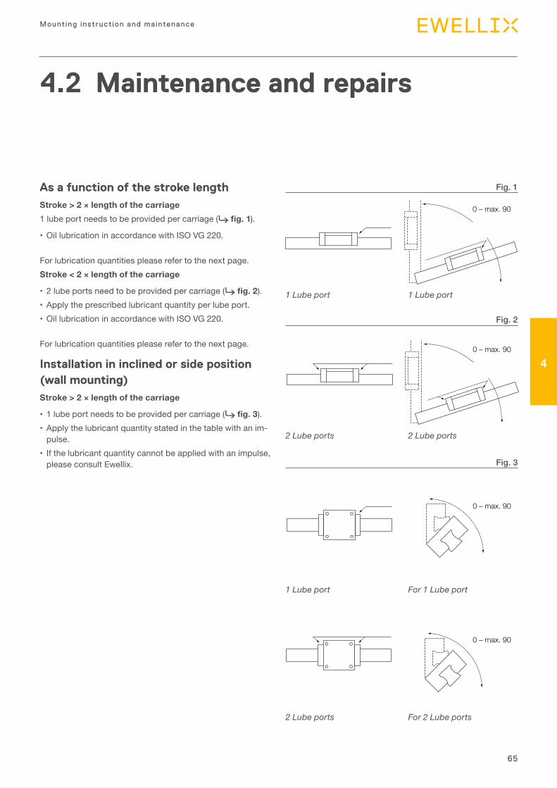
65
Mounting instruction and maintenance
4
4.2 Maintenance and repairs
As a function of the stroke lengthStroke > 2 × length of the carriage1 lube port needs to be provided per carriage (⮑ fig. 1).
• Oil lubrication in accordance with ISO VG 220.
For lubrication quantities please refer to the next page.Stroke < 2 × length of the carriage
• 2 lube ports need to be provided per carriage (⮑ fig. 2).• Apply the prescribed lubricant quantity per lube port.• Oil lubrication in accordance with ISO VG 220.
For lubrication quantities please refer to the next page.
Installation in inclined or side position (wall mounting)Stroke > 2 × length of the carriage
• 1 lube port needs to be provided per carriage (⮑ fig. 3).• Apply the lubricant quantity stated in the table with an im-
pulse.• If the lubricant quantity cannot be applied with an impulse,
please consult Ewellix.
1 Lube port
1 Lube port
2 Lube ports
2 Lube ports
1 Lube port
For 1 Lube port
2 Lube ports
For 2 Lube ports
Fig. 1
Fig. 2
Fig. 3
1 Lube port
2 Lube ports
1 Lube port
1 Lube ports
1 Lube port
0 – max. 90
2 Lube ports
0 – max. 90
For 1 lube port
0 – max. 90
For 2 lube ports
0 – max. 90
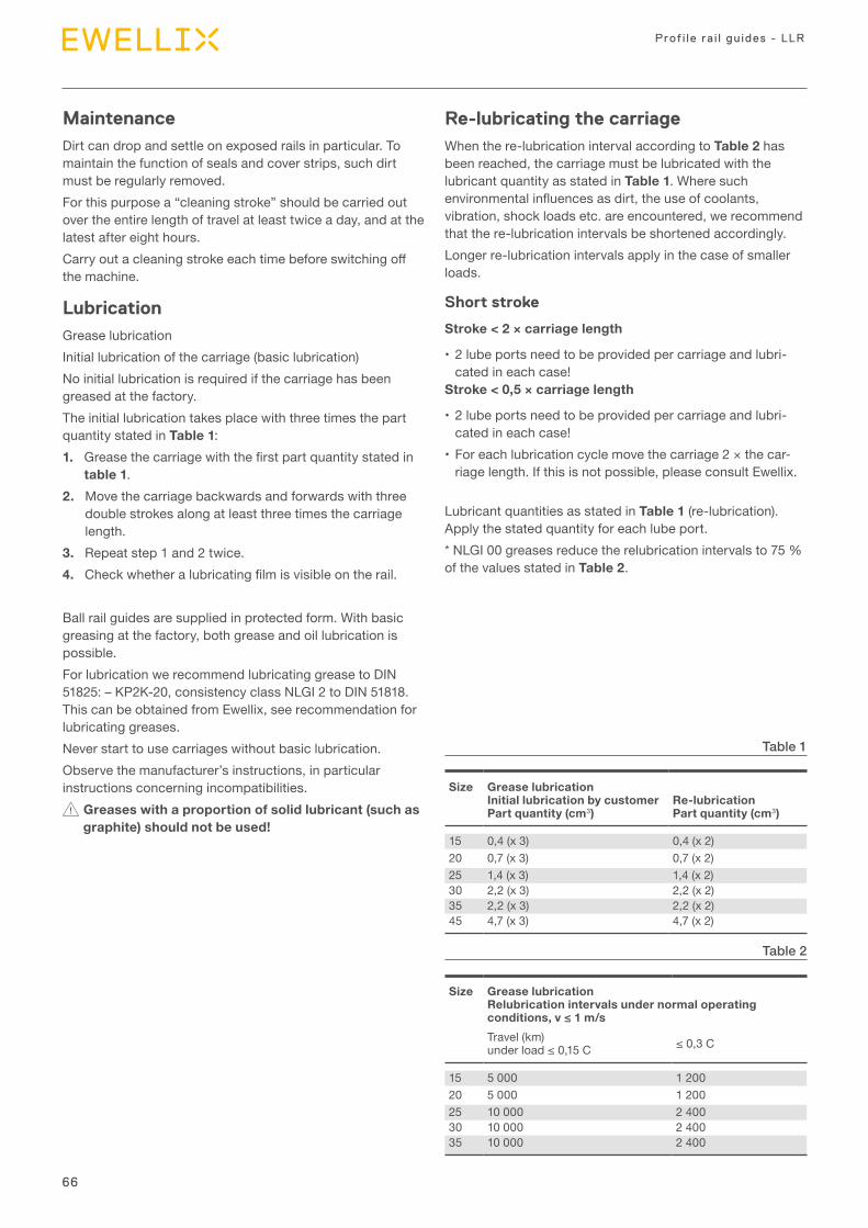
66
Prof i le ra i l gu ides - LLR
MaintenanceDirt can drop and settle on exposed rails in particular. To maintain the function of seals and cover strips, such dirt must be regularly removed.For this purpose a “cleaning stroke” should be carried out over the entire length of travel at least twice a day, and at the latest after eight hours.Carry out a cleaning stroke each time before switching off the machine.
LubricationGrease lubricationInitial lubrication of the carriage (basic lubrication)No initial lubrication is required if the carriage has been greased at the factory.The initial lubrication takes place with three times the part quantity stated in Table 1:1. Grease the carriage with the first part quantity stated in
table 1.2. Move the carriage backwards and forwards with three
double strokes along at least three times the carriage length.
3. Repeat step 1 and 2 twice.4. Check whether a lubricating film is visible on the rail.
Ball rail guides are supplied in protected form. With basic greasing at the factory, both grease and oil lubrication is possible.For lubrication we recommend lubricating grease to DIN 51825: – KP2K-20, consistency class NLGI 2 to DIN 51818. This can be obtained from Ewellix, see recommendation for lubricating greases.Never start to use carriages without basic lubrication.Observe the manufacturer’s instructions, in particular instructions concerning incompatibilities.
Greases with a proportion of solid lubricant (such as graphite) should not be used!
Re-lubricating the carriageWhen the re-lubrication interval according to Table 2 has been reached, the carriage must be lubricated with the lubricant quantity as stated in Table 1. Where such environmental influences as dirt, the use of coolants, vibration, shock loads etc. are encountered, we recommend that the re-lubrication intervals be shortened accordingly.Longer re-lubrication intervals apply in the case of smaller loads.
Short stroke
Stroke < 2 × carriage length
• 2 lube ports need to be provided per carriage and lubri-cated in each case!
Stroke < 0,5 × carriage length
• 2 lube ports need to be provided per carriage and lubri-cated in each case!
• For each lubrication cycle move the carriage 2 × the car-riage length. If this is not possible, please consult Ewellix.
Lubricant quantities as stated in Table 1 (re-lubrication). Apply the stated quantity for each lube port.* NLGI 00 greases reduce the relubrication intervals to 75 % of the values stated in Table 2.
Size Grease lubrication Initial lubrication by customer Part quantity (cm3)
Re-lubrication Part quantity (cm3)
15 0,4 (x 3) 0,4 (x 2)20 0,7 (x 3) 0,7 (x 2)25 1,4 (x 3) 1,4 (x 2)30 2,2 (x 3) 2,2 (x 2)35 2,2 (x 3) 2,2 (x 2)45 4,7 (x 3) 4,7 (x 2)
Size Grease lubrication Relubrication intervals under normal operating conditions, v ≤ 1 m/sTravel (km)under load ≤ 0,15 C ≤ 0,3 C
15 5 000 1 20020 5 000 1 20025 10 000 2 40030 10 000 2 40035 10 000 2 400
Table 1
Table 2
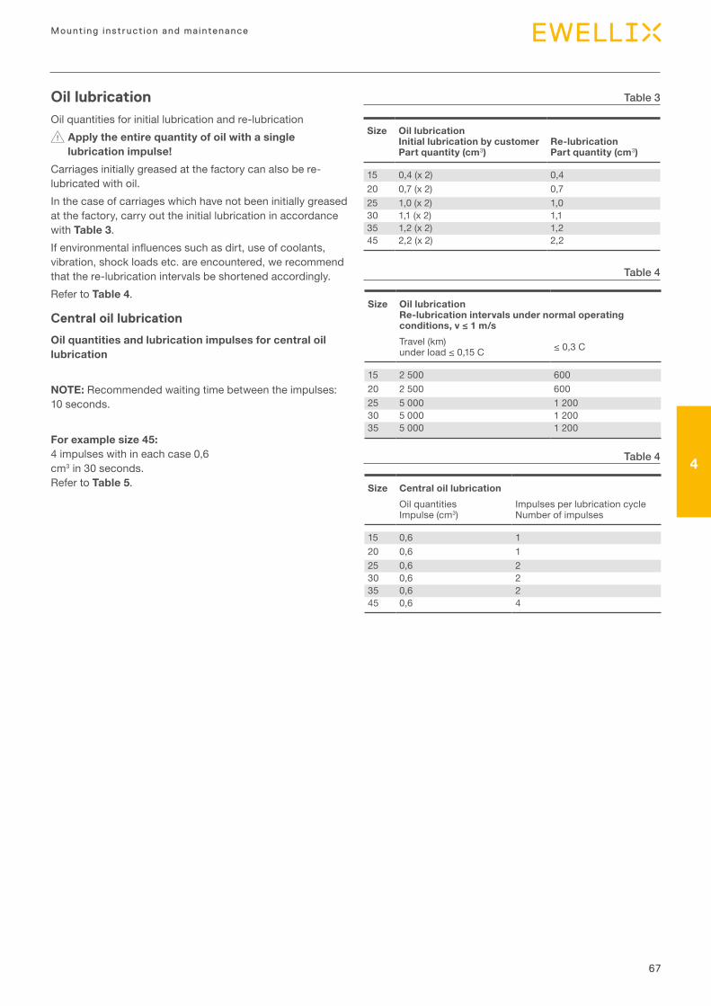
67
Mounting instruction and maintenance
4
Size Oil lubrication Re-lubrication intervals under normal operating conditions, v ≤ 1 m/sTravel (km)under load ≤ 0,15 C ≤ 0,3 C
15 2 500 60020 2 500 60025 5 000 1 20030 5 000 1 20035 5 000 1 200
Size Central oil lubricationOil quantities Impulse (cm3)
Impulses per lubrication cycle Number of impulses
15 0,6 120 0,6 125 0,6 230 0,6 235 0,6 245 0,6 4
Oil lubrication Oil quantities for initial lubrication and re-lubrication
Apply the entire quantity of oil with a single lubrication impulse!
Carriages initially greased at the factory can also be re-lubricated with oil.In the case of carriages which have not been initially greased at the factory, carry out the initial lubrication in accordance with Table 3.If environmental influences such as dirt, use of coolants, vibration, shock loads etc. are encountered, we recommend that the re-lubrication intervals be shortened accordingly.Refer to Table 4.
Central oil lubrication
Oil quantities and lubrication impulses for central oil lubrication
NOTE: Recommended waiting time between the impulses: 10 seconds.
For example size 45: 4 impulses with in each case 0,6 cm3 in 30 seconds. Refer to Table 5.
Size Oil lubrication Initial lubrication by customer Part quantity (cm3)
Re-lubrication Part quantity (cm3)
15 0,4 (x 2) 0,420 0,7 (x 2) 0,725 1,0 (x 2) 1,030 1,1 (x 2) 1,135 1,2 (x 2) 1,245 2,2 (x 2) 2,2
Table 3
Table 4
Table 4
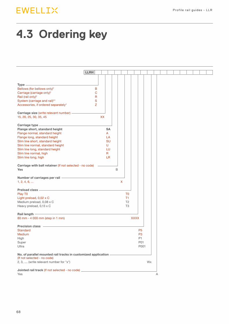
68
Prof i le ra i l gu ides - LLR
Type Bellows (for bellows only)* BCarriage (carriage only)* CRail (rail only)* RSystem (carriage and rail)** SAccessories, if ordered separately* Z
Carriage size (write relevant number)15, 20, 25, 30, 35, 45 XX
Carriage type Flange short, standard height SAFlange normal, standard height AFlange long, standard height LASlim line short, standard height SUSlim line normal, standard height USlim line long, standard height LUSlim line normal, high RSlim line long, high LR
Carriage with ball retainer (If not selected - no code)Yes B
Number of carriages per rail1, 2, 4, 6, ... X
Preload classPlay T0 T0Light preload, 0,02 x C T1Medium preload, 0,08 x C T2Heavy preload, 0,13 x C T3
Rail length80 mm - 4 000 mm (step in 1 mm) XXXX
Precision classStandard P5Medium P3High P1Super P01Ultra P001
No. of parallel mounted rail tracks in customized application (If not selected - no code)2, 3, .... (write relevant number for "x") Wx
Jointed rail track (If not selected - no code)Yes A
4.3 Ordering key
LLRH
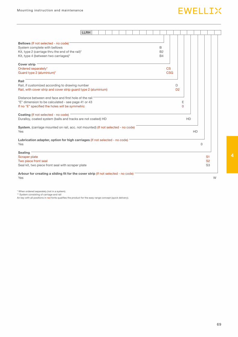
69
Mounting instruction and maintenance
4
LLRH
* When ordered separately (not in a system).** System consisting of carriage and railAn key with all positions in red fonts qualifies the product for the easy range concept (quick delivery).
Bellows (If not selected - no code)System complete with bellows BKit, type 2 (carriage thru the end of the rail)* B2Kit, type 4 (between two carriages)* B4
Cover stripOrdered separately* CSGuard type 2 (aluminium)* CSG
RailRail, if customized according to drawing number DRail, with cover strip and cover strip guard type 2 (aluminium) D2
Distance between end face and first hole of the rail"E" dimension to be calculated - see page 41 or 43 EIf no "E" specified the holes will be symmetric 0
Coating (If not selected - no code)Duralloy, coated system (balls and tracks are not coated) HD HD
System, (carriage mounted on rail, acc. not mounted) (If not selected - no code)Yes HD
Lubrication adapter, option for high carriages (If not selected - no code)Yes 0
SealingScraper plate S1Two piece front seal S2Seal kit, two piece front seal with scraper plate S3
Arbour for creating a sliding fit for the cover strip (If not selected - no code)Yes W


ewellix.com © Ewellix
All contents of this publication are the property of Ewellix, and may not be re-
produced or given to third parties (even extracts) without permission. Although
great care has been taken in the production of this catalog, Ewellix does not take
any responsibility for damage or other loss resulting from omissions or typo-
graphical errors. The photo may differ slightly in appearance from the actual
product. Due to continuous improvements being made in our products, the pro-
duct’s appearance and specifications are subject to change without notice.
PUB NUM IL-06016-EN-May 2020
Certain image(s) used under license from Shutterstock.com.
SKF and SKF logo are trademarks of the SKF Group