Embed Size (px)
Citation preview

Precision rail guides

Contents
SKF – the knowledge engineering company . . . . . . . . . . . . . 4
1 General information . . . . . . . . . . . . . . . . . . . . . . . . . . . 6
1.1 Introduction. . . . . . . . . . . . . . . . . . . . . . . . . . . . . . . . . . 6
1.2 Features and benefits . . . . . . . . . . . . . . . . . . . . . . . . . . 7
1.3 Product overview . . . . . . . . . . . . . . . . . . . . . . . . . . . . . 8
1.4 ACS in general . . . . . . . . . . . . . . . . . . . . . . . . . . . . . . . . 10
1.5 SKF precision rail guides in kit packaging . . . . . . . . . . . . 12
1.6 Technical data . . . . . . . . . . . . . . . . . . . . . . . . . . . . . . . . 13
1.6.1 Materials . . . . . . . . . . . . . . . . . . . . . . . . . . . . . 13
1.6.2 Coating . . . . . . . . . . . . . . . . . . . . . . . . . . . . . . . 13
1.6.3 Permissible operating temperatures . . . . . . . . . 13
1.6.4 Permissible speed and acceleration . . . . . . . . . 13
1.6.5 Permissible minimum load . . . . . . . . . . . . . . . . 13
1.6.6 Permissible maximum load . . . . . . . . . . . . . . . 13
1.6.7 Friction . . . . . . . . . . . . . . . . . . . . . . . . . . . . . . . 13
1.6.8 General rigidity behaviour . . . . . . . . . . . . . . . . . 14
1.6.9 Precision classes of rails . . . . . . . . . . . . . . . . . . 14
1.6.10 Precision of rolling elements . . . . . . . . . . . . . . . 15
1.6.11 Dimensional accuracy . . . . . . . . . . . . . . . . . . . . 15
1.6.12 Grading . . . . . . . . . . . . . . . . . . . . . . . . . . . . . . 15
1.6.13 Jointed rails . . . . . . . . . . . . . . . . . . . . . . . . . . . 16
1.7 Dimensioning of precision rail guide systems. . . . . . . . . 17
1.7.1 The concept of static safety factor calculation . . 17
1.7.2 The method of static safety factor calculation . . 17
1.7.3 Rating life . . . . . . . . . . . . . . . . . . . . . . . . . . . . 18
1.7.4 Rating life calculation . . . . . . . . . . . . . . . . . . . . 18
1.7.5 Service life . . . . . . . . . . . . . . . . . . . . . . . . . . . . 18
1.7.6 Cross reference to related chapters . . . . . . . . . . 18
1.8 Determination of effective load ratings . . . . . . . . . . . . . 19
1.8.1 Static and dynamic load ratings given in
the catalogue . . . . . . . . . . . . . . . . . . . . . . . . . . 19
1.8.2 Influence of hardness . . . . . . . . . . . . . . . . . . . 20
1.8.3 Influence of operating temperature . . . . . . . . . 20
1.8.4 Rail guide arrangements . . . . . . . . . . . . . . . . . 21
1.8.5 Rail guide kinematics . . . . . . . . . . . . . . . . . . . . 21
1.8.6 Number of rolling elements z, zT . . . . . . . . . . . 24
1.8.7 General geometry of a rail guide system . . . . . . 25
1.9 Calculation of bearing loads . . . . . . . . . . . . . . . . . . . . 26
1.9.1 Transfer of external loads to Fy, Fz, Mx, My, Mz . 26
1.9.2 Preload force . . . . . . . . . . . . . . . . . . . . . . . . . 27
1.9.3 Transfer of Fy, Fz, Mx, My, Mz to one load . . . . . 27
1.9.4 Influence of stroke length on equivalent
dynamic load rating . . . . . . . . . . . . . . . . . . . . 28
1.9.5 Equivalent dynamic mean load . . . . . . . . . . . . 28
1.9.6 Maximum resulting load . . . . . . . . . . . . . . . . . 28
1.9.7 Elaborated equation for the static safety factor 29
1.9.8 Elaborated equation for the rating life . . . . . . . 29
1.10 Example dimensioning calculation . . . . . . . . . . . . . . . 30
1.11 Rigidity calculation . . . . . . . . . . . . . . . . . . . . . . . . . . . 36
1.11.1 Determination of elastic deformation
using the nomogram . . . . . . . . . . . . . . . . . . . 36
1.11.2 Determination of resulting deflection of
a rail guide system . . . . . . . . . . . . . . . . . . . . . 42
1.11.3 Calculation example for the resulting
deflection . . . . . . . . . . . . . . . . . . . . . . . . . . . . 43
1.12 Technical data of precision rail guides with
slide coating . . . . . . . . . . . . . . . . . . . . . . . . . . . . . . . . 44
1.12.1 Surface pressure . . . . . . . . . . . . . . . . . . . . . . 44
1.12.2 Wear . . . . . . . . . . . . . . . . . . . . . . . . . . . . . . . 44
1.12.3 Frictional properties . . . . . . . . . . . . . . . . . . . . 44
1.12.4 Temperature range . . . . . . . . . . . . . . . . . . . . 45
1.12.5 Chemical and humidity resistance . . . . . . . . . 45
1.13 Legend . . . . . . . . . . . . . . . . . . . . . . . . . . . . . . . . . . . . 46
2 Product data . . . . . . . . . . . . . . . . . . . . . . . . . . . . . . . . 47
2.1 LWR / LWRB . . . . . . . . . . . . . . . . . . . . . . . . . . . . . . . . 47
2.2 LWRE . . . . . . . . . . . . . . . . . . . . . . . . . . . . . . . . . . . . . 52
2.3 LWRE ACS . . . . . . . . . . . . . . . . . . . . . . . . . . . . . . . . . 57
2.4 LWRE / LWRB ACSM . . . . . . . . . . . . . . . . . . . . . . . . . . 61
2.5 LWRM / LWRV . . . . . . . . . . . . . . . . . . . . . . . . . . . . . . 65
2.6 LWM / LWV . . . . . . . . . . . . . . . . . . . . . . . . . . . . . . . . . 69
2.7 LWM / LWV ACSZ . . . . . . . . . . . . . . . . . . . . . . . . . . . . 73
2.8 LWRPM / LWRPV . . . . . . . . . . . . . . . . . . . . . . . . . . . . 77
2.9 Other products . . . . . . . . . . . . . . . . . . . . . . . . . . . . . . 80
2.9.1 LWML / LWV . . . . . . . . . . . . . . . . . . . . . . . . . . 80
2.9.2 LWN / LWO . . . . . . . . . . . . . . . . . . . . . . . . . . . 80
2.9.3 LWJ / LWS flat rail guides . . . . . . . . . . . . . . . . 80
2.10 GCL / GCLA standard slides . . . . . . . . . . . . . . . . . . . . . 81
2.11 LZM miniature slide . . . . . . . . . . . . . . . . . . . . . . . . . . 86

3 Recommendations . . . . . . . . . . . . . . . . . . . . . . . . . . . . 90
3.1 Design rules . . . . . . . . . . . . . . . . . . . . . . . . . . . . . . . . . 90
3.1.1 Designated use . . . . . . . . . . . . . . . . . . . . . . . . . 90
3.1.2 Typical mounting – clamped arrangement . . . . 90
3.1.3 Accuracy of mounting surfaces . . . . . . . . . . . . . 90
3.1.4 End pieces logic . . . . . . . . . . . . . . . . . . . . . . . . 91
3.1.5 Chamfers on the precision rail guides . . . . . . . . 92
3.1.6 Tolerance of distance between mounting holes . 92
3.1.7 Calculation of J1 dimension . . . . . . . . . . . . . . . . 92
3.1.8 Special mounting screws LWGD . . . . . . . . . . . . 93
3.1.9 Preloading . . . . . . . . . . . . . . . . . . . . . . . . . . . . 94
3.1.10 Tightening torques for mounting screws . . . . . . 94
3.2 Mounting . . . . . . . . . . . . . . . . . . . . . . . . . . . . . . . . . . . . 96
3.2.1 Important requirements . . . . . . . . . . . . . . . . . . 96
3.2.2 General mounting rules . . . . . . . . . . . . . . . . . . 96
3.2.3 Mounting of rail guides without
Anti-Creeping System . . . . . . . . . . . . . . . . . . . 96
3.2.4 Mounting of rail guides with
Anti-Creeping System . . . . . . . . . . . . . . . . . . . 97
3.3 Maintenance . . . . . . . . . . . . . . . . . . . . . . . . . . . . . . . . . 98
3.3.1 Lubrication . . . . . . . . . . . . . . . . . . . . . . . . . . . . 98
3.3.2 Relubrication interval . . . . . . . . . . . . . . . . . . . . 98
3.3.3 Repairs . . . . . . . . . . . . . . . . . . . . . . . . . . . . . . . 98
3.3.4 Stationary conditions / shipping / storage . . . . . 98
3.4 Ordering code . . . . . . . . . . . . . . . . . . . . . . . . . . . . . . . . 99
3.5 Specification sheet . . . . . . . . . . . . . . . . . . . . . . . . . . . . 103
3

From one simple but
inspired solution to
a misalignment
problem in a textile
mill in Sweden, and
fifteen employees in
1907, SKF has
grown to become a
global industrial
knowledge leader.
Over the years, we have built on our exper-
tise in bearings, extending it to seals, mecha-
tronics, services and lubrication systems.
Our knowledge network includes 46 000
employees, 15 000 distributor partners,
offices in more than 130 countries, and a
growing number of SKF Solution Factory
sites around the world.
Research and development
We have hands-on experience in over forty
industries based on our employees’ know-
ledge of real life conditions. In addition, our
world-leading experts and university part-
ners pioneer advanced theoretical research
and development in areas including tribol-
ogy, condition monitoring, asset manage-
ment and bearing life theory. Our ongoing
commitment to research and devel opment
helps us keep our customers at the forefront
of their industries.
Meeting the toughest challenges
Our network of knowledge and experience,
along with our understanding of how our
core technologies can be combined, helps
us create innovative solutions that meet the
toughest of challenges. We work closely with
our customers throughout the asset life
cycle, helping them to profitably and
re spon sibly grow their businesses.
SKF Solution Factory makes SKF knowledge and manu facturing expertise available locally to provide unique solutions and services to our customers.
Working with SKF IT and logistics systems and application experts, SKF Authorized Distributors deliver a valuable mix of product and application knowledge to customers worldwide.
Working for a sustainable future
Since 2005, SKF has worked to reduce the
negative environmental impact from our
operations and those of our suppliers. Our
continuing technology development resulted
in the introduction of the SKF BeyondZero
portfolio of products and services which im-
prove efficiency and reduce energy losses,
as well as enable new technol ogies har-
nessing wind, solar and ocean power. This
combined approach helps reduce the en vir-
on mental impact both in our oper ations and
our customers’ oper ations.
SKF – the knowledge engineering company
4

BearingsSKF is the world leader in the design, development and manufacture of high performance rolling bearings, plain bearings, bearing units and housings.
Machinery maintenanceCondition monitoring technologies and main-tenance services from SKF can help minimize unplanned downtime, improve operational efficiency and reduce maintenance costs.
Sealing solutionsSKF offers standard seals and custom engineered sealing solutions to increase uptime, improve machine reliability, reduce friction and power losses, and extend lubricant life.
MechatronicsSKF fly-by-wire systems for aircraft and drive-by-wire systems for off-road, agricultural and forklift applications replace heavy, grease or oil consuming mechanical and hydraulic systems.
Lubrication solutionsFrom specialized lubricants to state-of-the-art lubrication systems and lubrication management ser vices, lubrication solutions from SKF can help to reduce lubrication related downtime and lubricant consumption.
Actuation and motion controlWith a wide assortment of products – from actu-ators and ball screws to profile rail guides – SKF can work with you to solve your most pressing linear system challenges.
Our knowledge – your successSKF Life Cycle Management is how we combine our technology
platforms and advanced ser vices, and apply them at each stage
of the asset life cycle, to help our customers to be more
success ful, sustainable and profitable.
Working closely with you
Our objective is to help our customers
improve productivity, minimize main ten-
ance, achieve higher energy and resource
efficiency, and optimize designs for long
service life and reliability.
Innovative solutions
Whether the application is linear or rotary
or a combination, SKF engineers can work
with you at each stage of the asset life cycle
to improve machine performance by looking
at the entire application. This approach
doesn’t just focus on individual components
like bearings or seals. It looks at the whole
application to see how each com po nent in-
teracts with each other.
Design optimization and verification
SKF can work with you to optimize current
or new designs with proprietary 3-D mod-
ell ing software that can also be used as a
virtual test rig to confirm the integrity of the
design.
SKF Life Cycle Management
Design and developManufacture and test
Spe
cific
ation
Install a
nd com
mis
sion
Operate and monitor
Maintain and repair
5

1 General information
1.1 Introduction
As the world’s leading rolling bearing manu-
facturer, SKF supplies practically every type
of bearing for rotational and linear motion.
SKF is therefore in a position, both techni-
cally and economically, to meet almost any
customer requirement.
This catalogue covers the entire range of
SKF precision rail guides and accessories.
SKF precision rail guides are highly accurate
products for linear motion and are ideally
suited for use in a wide variety of machine
tools, machining centres, handling systems
and special machinery, as well as in meas-
uring and testing equipment and semi-con-
ductor production machines.
SKF precision rail guides are available in
many different designs, sizes and standard
lengths and which incorporate ball, roller or
needle roller assemblies and slide coatings.
They are supplied with the required acces-
sories for attachment and sealing. The use
of SKF precision rail guides enables the con-
struction of economical, clearance-free lin-
ear guides of almost any type and length,
according to the building block principle.
The characteristics of the precision rail
guides include:
• A constant, high degree of running
accuracy.
• Low-friction, stick-slip free operation.
• High speed of travel.
• Low heat generation.
• Low wear and high reliability.
• High rigidity.
• Excellent load carrying capacity.
If cage creeping is likely, in particular
when the guide is mounted vertically, preci-
sion rail guides with anti-creeping systems
(ACS) are an obvious choice, as they will
eliminate this problem. They are available
for nearly all types of rolling elements.
For applications characterised by high
accelerations or short strokes of high fre-
quency, SKF rail guides with slide coating
are recommended. These rail guides are
also suitable for machine tool applications
where the damping properties of the guides
are of greater importance than is the lower
friction of rolling element rail guides. For
those applications where precision rail
guides are unsuitable, for instance because
of their limited travel, SKF can supply alter-
native forms of linear guidance systems, like
profile rail guides or linear ball bearings.
All fast-selling precision rail guides are
also available in convenient kit packaging.
This ensures the complete delivery of all
components including end pieces and
screws in one package from stock.
This catalogue brings together all the
basic data that we believe will be of interest
to customers. For further specialised advice,
please contact your nearest SKF sales office.
6

1.2 Features and benefits
200100 300 500 800 1 000900
2345678
109
1
0 400 600 700
P10
P5
P2
Deviation in parallelism [µm]
Rail length [mm]
Cage creep test results
Permissible deviation in parallelism between reference surfaces and raceways
10
15
25
30
35
20
5
0
100 20 40 70 9080 10030 50 60
Axial displacement [mm]
Distance travelled [km]
Modular rangeWith the SKF modular range of precision rail guides, outer rail dimensions remain the same, but rolling elements are interchangeable to best meet application demands. With this design modularity, customers can easily increase load rating or extend rating life without having to redesign the equipment. The SKF modular range of precision rail guides covers 80% of dimensions on the market. Additionally, the customer can chose between ball assemblies, crossed roller assemblies, crossed roller assemblies with ACS/ACSM, needle roller assemblies and slide coatings.A
B
Extreme accuracy and positioning repeatabilityCompared to other linear guiding products, precision rail guides provide the highest linear guiding accuracy. Precision rail guides from SKF are available in three different precision classes to meet a range of requirements for preci-sion. The increased accuracy and repeatability enables higher productivity and product quality in diverse applications, e.g. semi-conductors, machine tools, measurement and testing equipment, and medical equipment.
Higher load rating and rigidityCompared to conventional LWR precision rail guides, SKF optimized the inter-nal geometry and developed LWRE precision rail guides for applications that demand robust performance. Part of our modular range, LWRE precision rail guides feature rollers with a 33% larger diameter and utilize the entire roller length than those in LWR rail guides. These LWRE design upgrades fivefolded the load ratings and doubled the rigidity vs. LWR rail guides. In operation, the increased load rating and rigidity helps to increase process stability and reliability, ultimately extending equipment service life and reducing total cost of ownership.
Anti-creeping systemSKF developed the industry’s first anti-cage-creep solution. It keeps the movement of the cage in the required position at the loaded zone, avoids cage creep from high operational speed and acceleration to uneven load distribu-tion and weak adjacent parts, and prevents unplanned downtime and addi-tional maintenance.
In addition, due to defined cage position, SKF precision rail guides with anti-creeping system, or ACS, enable increased accuracy, higher accelera-tions (tested up to 160 m/s2), and reliable vertical installation.
without anti-creeping system
with anti-creeping system
1
7

1.3 Product overview
8

SKF can offer a large assortment of preci-
sion rail guides († table 1). The different
versions, mainly characterized by their type
of rolling elements, are as follows:
• Ball assemblies of LWRB series.
• Ball assemblies with Anti-Creeping
System of LWRB ACSM series.
• Crossed roller assemblies of standard
LWR series.
• Crossed roller assemblies of optimised
LWRE series.
• Crossed roller assemblies with Anti-
Creeping System of LWRE ACS series.
• Crossed roller assemblies with Anti-
Creeping System of LWRE ACSM series.
• Needle roller assemblies of LWRM/LWRV
series.
• Needle roller assemblies of LWM/LWV
series.
• Needle roller assemblies with Anti-Creep-
ing System of LWM/LWV ACSZ series.
• Slide coating of LWRPM/LWRPV series.
The following table shows the complete
range of SKF precision rail guides, together
with all available sizes. The blue shaded areas
indicate the sizes included in the Modular
Range. Contrary to the current lack of uni-
formity within the market, the interchange-
able precision rail guides of the Modular
Range are all within the same outer dimen-
sions († fig. 1). For fast delivery, please
refer to the rail guides that are available in
kit packaging.
Fig. 1
Market situation
SKF modular range
Table 1
Product overview
Type Size (A¥B mm)1 2 3 2211 4 6 9 12 158,5¥4 12¥6 18¥8 22¥11 25¥12 30¥15 31¥15 40¥20 44¥22 50¥25 58¥28 60¥35 70¥40 71¥36 80¥50
LWRB X X – – – – – – – – – – – – –
LWRB ACSM – L – – – – – – – – – – – – –
LWR – – X – – – X – X – L – – – –
LWRE – – X L X – X – X – – – – – –
LWRE ACS – – X L L – X – L – – – – – –
LWRE ACSM – – X L L – X – L – – – – – –
LWRM / V – – – – – – X – X – – – – – –
LWM / V – – – – – X – X – X – L L – L
LWM / V ACSZ – – – – – L – L – L – L L – L
LWRPM / V – – X – – – X – X – – – – – –
X = Prompt delivery in standard lengths (see specific product tables) = Modular rangeL = Delivery time on request – = Not available
A
B
1
9

1.4 ACS in general
Many users are familiar with “cage-creep-
ing” in conventional precision rail guides.
This occurs when the cage moves out of
its intended position, adversely affecting
performance and possibly requiring service.
This effect may occur, for example, as a
result of high acceleration, uneven load
distribution or vertical mounting. SKF has
solved this problem by offering highly
sophisticated Anti-Creeping Systems (ACS)
for most guiding types.
Advantages:
• Cage-creeping eliminated.
• Suitable for high acceleration, vertical
mounting and uneven load distribution.
• Increased accuracy due to defined posi-
tion of the cage.
• Easily interchangeable with standard
precision rail guides because they have
identical dimensions.
• Less downtime and maintenance.
LWRE with ACS
The original anti-creeping system for all
types of LWRE rail guides.
LWRE with ACSM
Refinement of our own ACS solution led to
version ACSM for LWRE rail guides with a
maximum length of 400 mm. The cage, with
an involute-toothed control gear made of
brass, and involute teeth directly machined
into the rail, are especially suitable for high
accelerations.
LWM / LWV with ACSZ
For precision rail guides with needle roller
cages, SKF can offer version ACSZ.
Both rails are equipped with gear racks
made of steel. The cage carries two steel
control gears that help to ensure the correct
cage position.
LWRE with ACS
LWRE with ACSM
LWM / LWV with ACSZ
10

Rails for anti-creeping cages
Rails for ACS- or ACSZ-cages can be
designed for a specified stroke or maximum
stroke, with the length of the toothing in the
rail varied accordingly († fig. 2 and 3). Rails
for ACSM-cages are always made for maxi-
mum stroke.
A rail for maximum stroke has teeth along
its entire length. This may be required for
mounting, maintenance or dismounting
purposes. Rails for ACS- or ACSZ-cages are
delivered with maximum stroke as standard
and no special ordering code is required. For
rails with a specified stroke, the length of the
stroke, which is symmetrical to the rail, must
be stated in millimetres after the suffix
ACS / ACSZ. ACS- and ACSZ-cages must be
operated only along the specified stroke
length to ensure that the control gear is not
damaged.
Ordering example – maximum stroke:
4x LWRE 6500 ACS
2x LWAKE 6x30 ACS
8x LWERE 6
Ordering example – specified stroke of
340 mm:
4x LWRE 6500 ACS 340
2x LWAKE 6x30 ACS
8x LWERE 6
Ordering example – kit packaging:
LWRE 6200 ACSM-KIT
Fig. 2
LWRE ACS standard stroke
Fig. 3
LWRE ACS specified stroke
1
11

Advantages of rail guide kits
• All components required are supplied
ready-to-mount and can be ordered with
a single order number.
• Most kits are available from stock.
• Cage length is easily adjustable.1)
• Load capacities are already calculated for
the kit.2)
• Available with ACS or ACSM for effective
prevention of cage-creeping.
• Rails for ACS- or ACSM-cages with tooth-
ing along entire length (rails for maximum
stroke).
1.5 SKF precision rail guides in kit packagingTo simplify the ordering process and ware-
housing for our customers, SKF offers preci-
sion rail guides in pre-defined kits. Each kit
consists of 4 rails in precision class P10, 2
cages and 8 end pieces (ACSM kits without
end pieces). The available kits can be found
in the specific rail guide chapters. On
request it is possible to order a kit with two
rails in standard length and two short rails
with lead in radius. Additionally the number
of rolling elements can be varied, see order-
ing code.
Completely customised precision rail
guide sets are also possible on request.
1) Do not cut the cage shorter than 2/3 of the total rail length.2) Load capacities are given for a kit of 4 rails and 2 cages in clamped arrangement (C0eff slide, Ceff slide)
12

1.6 Technical data
1.6.1 MaterialsAs standard, precision rails are manufac-
tured from tool steel 90MnCrV8 (1.2842)
with a hardness between 58 and 62 HRC.
However, if required by the application, the
rails can also be supplied in stainless steel,
e.g. X90CrMoV18 (1.4112). All rails from
the LWRE ACSM series are made of stain-
less steel X46Cr13 (1.4034) or X65Cr13
(1.4037).
Standard rolling elements are made from
carbon chromium steel 100Cr6 (1.3505)
with a hardness between 58 and 65 HRC.
Stainless steel rolling elements are available
on request.
The cages of SKF rolling element assem-
blies are manufactured from hard plastic or
aluminium. The material of LWAKE crossed
roller units is POM, and for all other rolling
element assemblies, PA 12 or equivalent,
sometimes reinforced with glass fibres.
Aluminium cages are made of AlMgSi0,5
(EN AW-6060). For other cage materials
such as Peek, steel, brass, etc., please
contact SKF.
Standard end pieces are made of black-
ened steel. Additionally, the standard end
pieces can be supplied as chromed end
pieces when ordered with suffix “/HV”.
1.6.2 CoatingFor corrosive environments, the rails can be
protected with a special TDC (Thin Dense
Chrome) coating. This coating, with a layer
hardness of 900 to 1300 HV, substantially
improves corrosion resistance and thus
increases wear resistance under critical
operating conditions. The salt spray test,
which complies with DIN EN ISO 9227,
resulted in 72h corrosion protection. The
coating is matt grey in colour and complies
with RoHs requirements. The load capacity
is not affected by the coating. Due to the
electrolytic process, the mounting holes and
other grooves or drills might not be fully
coated. The suffix for ordering is “/ HD”.
1.6.3 Permissible operating temperatures
The range of operating temperature for SKF
precision rail guides depends largely on the
particular cage type used. Guides with metal
cages and end pieces without wipers can
generally be used up to +120 °C. For rail
guides with plastic components, the operat-
ing temperature range is –30 °C to +80 °C.
Please note that the temperature limit of the
used lubricant must also be taken into
account.
Permanently higher operating tempera-
tures for precision rail guides without plastic
components are possible but the hardness
of the material and thus the load carrying
capacity will decrease. The detailed explana-
tion of the influence of higher temperatures
on the load carrying capacity (factor ft) can
be found in chapter 1.8.3. The accuracy of
the rail guide worsens with increasing tem-
perature due to changes in the material
structure and dimensional changes.
1.6.4 Permissible speed and acceleration
SKF precision rail guides that are correctly
mounted and preloaded, can be used for
running speeds up to 2 m/s and accelera-
tions up to 25 m/s2. Needle roller cages can
be accelerated with maximum 100 m/s2. For
cages with ACSM, the maximum accelera-
tion is 160 m/s2 and for cages with ACSZ the
value is 100 m/s2. Higher running speeds
and accelerations are possible, depending
on bearing design, bearing size, applied
load, lubricant and bearing preload. In such
instances, please consult SKF.
1.6.5 Permissible minimum load
To prevent the rolling elements from sliding
on the raceway during operation at higher
speeds or high acceleration, the precision
rail guide system must be loaded at all times
with a minimum 2% of the dynamic load
rating. This is particularly important for
applications characterized by highly dynamic
cycles. Precision rail guide systems preloaded
according to the table, Tightening torques of
set screws († chapter 3.1.10), are typically
able to satisfy the stated minimum load
requirements.
1.6.6 Permissible maximum load
ISO 14728 Part 1 stipulates that calculation
of bearing life is valid only when the equiva-
lent dynamic mean load Pm of a precision
rail guide does not exceed 50% of the
dynamic load rating C. Any higher loading
leads to an imbalance of stress distribution,
which can have a negative impact on bear-
ing life. As stated in ISO 14728 Part 2, the
maximum load should not exceed 50% of
the static load rating C0.
1.6.7 FrictionFriction in a precision rail guide with rolling
elements depends not only on the loading,
but on a number of other factors, notably
the type and size of the bearing, the operat-
ing speed, and the properties of the lubri-
cant. The cumulative running resistance of
a rail guide is composed of the rolling and
sliding friction at the contact zone of the
rolling elements, friction at the points of
sliding contact between the rolling elements
and cage, churning work within the lubricant
and friction from the seals or wipers.
The coefficients of friction under normal
operating conditions, with grease lubrication
and good mounting accuracy, are between
0,0005 and 0,004. For rail guides fitted with
wipers, the coefficient of friction and the
starting friction is significantly higher due to
the friction of the wipers themselves.
1
13

1.6.8 General rigidity behaviour
The rigidity of a precision rail guide
(expressed in N/µm) is defined as the ratio
between the acting external load and the
elastic deflection resulting in the rail guide.
Besides the load carrying capacity, rigidity is
one of the most important selection criteria
for a precision rail guide system. The elastic
deflection of a system depends on the mag-
nitude and direction of the external load, the
preload, the type of rail guide including size
and cage length, and the mechanical prop-
erties of the adjacent support structure,
including screws and joints between compo-
nents. On a preloaded rail guide system the
deflection under load within a given load
range will be less than for a rail guide with-
out preload. Variations in contact geometry
are the main factors contributing to the
general rigidity behaviour of the cage types
(† diagram 3). The details are explained in
chapter 1.11.
1.6.9 Precision classes of railsIn order to meet the precision requirements
of rail guide systems, SKF produces rails in
three different precision classes. These are
classified according to the parallelism between
the raceways and reference surfaces A, (as
indicated, on the reverse side of the SKF
label), and B. See table 2 and fig. 4.
Table 2
Tolerance t of parallelism to reference surfaces
Rail length Precision class> ≤ P10 P5 P2
mm µm
0 100 2 1 1100 200 3 2 1200 300 4 2 1
300 400 5 2 2400 500 6 3 2500 600 6 3 2
600 700 7 4 2700 800 8 4 2800 900 8 5 2
900 1 000 9 5 21 000 1 200 10 6 31 200 1 400 11 6 3
1 400 1 6001) 12 7 3
1) Rail length > 1 600 mm, please contact SKF
P10
This is the standard precision class and meets
the requirements of general machinery. The
tolerance of parallelism for a 1 000 mm long
rail is maximum 9 µm.
P5
Precision class P5 satisfies the demands
normally made on the running accuracy for
machine tool applications. The tolerance of
parallelism for a 1 000 mm long rail is 5 µm
maximum.
P2
Precision class P2 is for the most exacting
demands. Rails made to this precision class
should only be used when the associated
components are manufactured to a corre-
spondingly high degree of precision. Rails of
precision class P2 will be manufactured by
SKF to special order.
If the requisite accuracy on the order is
not specified, rails with standard P10
tolerances will be supplied.
Fig. 4
B
A A
B
t B t B
t A t A
Diagram 3
General rigidity behaviour of different rolling elements
External load [N]
LWRB + LWRB
LWRE + LWRE
LWRV + LWRM
LWR + LWR
Deflection [µm]
14

Fig. 5
H2
H1
BT
A
Table 3
Precision of rolling elements
Rolling element Norm Class Roundness Sorting Comment
– – – µm µm –
Balls DIN 5401-1 G10 0,25 1 Standard
Cylinder roller DIN 5402-1 G1 0,5 1 Standard
Needle roller DIN 5402-3 G2 1 2 Standard Not mentioned in DIN G1 0,5 1 Suffix /G1
1.6.10 Precision of rolling elements
The rolling elements used in precision rail
guide cages are of very high quality and
have a specification according to table 3.
Besides the standard type, needle roller
cages can be delivered in class G1, when
ordered with suffix /G1.
1.6.11 Dimensional accuracySKF precision rail guides are produced with
the following tolerances († fig 5):
Width A: +0 / –0,3 mm
Height B: +0 / –0,2 mm
Centre Height H1 = H2: ± 5 µm1)
Assembly Height T = H1 + H2: ± 10 µm1)
Rail length Lrail:
Lrail ≤ 300: ± 0,3 mm
Lrail > 300: ± 0,001 mm ¥ Lrail
1.6.12 GradingFor the typical “clamped” arrangement, four
precision rail guides are needed. To reach
the best performance in terms of lifetime,
rigidity and running behaviour, it is impor-
tant that the centre height of the four rails is
within a small tolerance. This is the reason
why SKF rails are graded and packed
together according following rules:
Rails for crossed roller or ball cages:
Four rails are matched to each other and
packaged as a set.
Rails for needle roller cages or slide
coatings:
Two M shaped and two V shaped rails are
matched and packaged as pairs.
Because of the very close standard toler-
ance of the centre height, it would also be
possible to pair any rail for a standard appli-
cation (precision class P10) if necessary.
1) for rail length Lrail < 1 000 mm
1
15

1.6.13 Jointed railsJointed rails are always graded and well-
sorted by SKF to ensure smooth running.
They are delivered with markings as indi-
cated in fig. 6. For rails composed of two or
more sections, the tolerance for the total
length is ±2 mm.
Fig. 6
Set 1
1 - 1A
1 - 2A 1 - 2A
1 - 1A 1 - 1B 1 - 1B
1 - 2B 1 - 2B
1 - 3B 1- 3B1 - 3A 1- 3A
1 - 4A 1- 4A 1 - 4B 1- 4B
1 1 A
Set number
Rail track
Joint
16

1.7 Dimensioning of precision rail guide systemsOften it is not possible to build a prototype
machine just to find out which the most
suitable guiding for a given application is.
Instead, the following established and
proven procedures are recommended:
• Calculation of rating life
• Calculation of static safety factor
These two calculation methods must con-
sider all loads and forces acting on the
precision rail guide system. Representatives
of the acting bearing load that describe the
whole load case are needed. These repre-
sentatives must combine all forces, leverarms
and torque loads, which can vary by time or
stroke († chapter 1.9 and following). The
rating life of a precision rail guide with roll-
ing elements is defined as the total linear
distance travelled by the rails before the first
sign of material fatigue occurs on one of the
raceways and/or the rolling elements. For
the selection of rail guides based on rating
life calculation († chapter 1.7.3), the
dynamic load rating C, as defined in chapter
1.8, is used. It is expressed as the load that
results in a bearing life of 100 000 m.
1.7.1 The concept of static safety factor calculation
When selecting a precision rail guide, the
static safety factor calculation must be con-
sidered when one of the following cases
arises:
• The bearing operates under load at very
low speeds.
• The bearing operates at normal conditions
but must also accept heavy shock loads.
• The bearing is loaded stationary for long
periods of time.
• The bearing is loaded with P > 50% of the
dynamic load rating C where the theory of
rating life calculation is not valid any
more.
In all such cases, the permissible load is
determined not through material fatigue but
through the permanent physical deformation
at the contact zone of the rolling elements
and raceways. Load applied when stationary
or at very low operating speeds, as well as
heavy shock loads, causes flattening of the
rolling elements and results in damage to
the raceways. The damage may be uneven or
may be spaced along the raceway at intervals
corresponding to the rolling element separa-
tion. This permanent deformation leads to
vibration in the bearing, noisy running and
increased friction and even may cause a
decrease in preload and, in an advanced stage,
an increase in clearance. With continued
operation, this permanent deformation may
become a starting point for fatigue damage
due to resulting peak loads. The seriousness
of these phenomena will depend on the
particular bearing application.
1.7.2 The method of static safety factor calculation
When determining the bearing size according
to static load rating († chapter 1.8), one
must consider a certain relationship, known
as the static safety factor s0 , between the
static load rating C0 and the maximum static
load P0. The static safety factor s0 deter-
mines the degree of safety against excessive
permanent deformation of the rolling
elements and raceways. The static load
rating, C0, is defined as the static load that
would produce a permanent deformation of
0,0001 times the rolling element diameter.
Experience shows that, depending on the
contact conditions, a maximum Hertzian
pressure of 4 000 MPa is permissible at the
zone of maximum load without affecting the
running qualities of the bearing. See also
ISO 14728-2.
Table 4
Static safety factor depending on operating conditions
Operating conditions s0
Normal conditions > 1–2Smooth, vibration-free operation > 2–4Medium vibrations or impact loads 3–5High vibrations or impact loads > 5Overhead installations The general technical rules and standards in the
respective industrial sector must be observed. If the application poses a risk of serious injury, the user must take appropriate design and safety measures that will prevent all rails from becoming detached from the base (e.g. due to loss of rolling elements or failure of screw connections).
Calculation of the static safety factor
For a chosen precision rail guide and a
defined load case, the static safety factor s0
can be calculated by:
C0, eff slide C0, eff slides0 = JJKKL = JJJLL P0 Fres max
where
s0 = static safety factor
C0, eff slide = effective static load rating of
a slide [N]
P0 = maximum static load [N]
Fres max = maximum resulting load [N]
Based on practical experience, guideline val-
ues have been specified for the static safety
factor s0, which depend on the operating
mode and other external factors († table 4).
If, for example, the precision rail guide sys-
tem is exposed to external vibrations from
machinery in close proximity, higher safety
factors should be applied. Moreover, the load
transfer paths between a precision rail guide
system and its support structure should be
taken into account. In particular, the screw
connections must be examined for adequate
safety. For overhead installations of preci-
sion rail guides, higher safety factors should
be applied.
Note: The general technical rules and
standards in the respective industrial sector
also must be observed.
1
17

Requisite static load rating
For specific operating conditions with a
related recommended static safety factor
and a defined load case, the requisite static
load rating C0 can be calculated from the
following formula:
C0, eff slide = s0 P0 = s0 Fres max
where
C0, eff slide = effective static load rating of
a slide [N]
P0 = maximum static load [N]
s0 = static safety factor
Fres max = maximum resulting load [N]
1.7.3 Rating life In laboratory tests and in practice it is found
that the rating life of apparently similar
bearings under completely identical running
conditions can differ. Therefore, calculation
of the appropriate bearing size requires a
full understanding of the concept of bearing
rating life. All references to the dynamic load
rating of SKF precision rail guides apply to
the basic rating life, as covered by the ISO
definition (ISO 14728-1), in which the rating
life is understood as the life reached or
exceeded by 90% of a large group of identical
bearings. The majority of the bearings reach
a longer rating life , and half the total number
of bearings reach at least five times the
basic rating life.
1.7.4 Rating life calculationThe rating life of precision rail guides
expressed in km, Lns, can be calculated using
the following formula:
q C eff slide w p Lns = c1 100 JJKK < P z
In load cases where the length of travel and
stroke frequency is constant, it is often more
useful to calculate the rating lives in operat-
ing hours Lnh using formula 4:
5 107 q C eff slide w pLnh = c1 JKKK JJKK S n 60 < P z
where
Lns = modified basic rating life [km]
Lnh = modified basic rating life [h]
c1 = factor for reliability
Ceff slide = effective dynamic load rating of
a slide [N]
P = equivalent dynamic load [N]
p = life exponent; p = 3 for balls,
p = 10/3 for rollers
n = stroke frequency
[double strokes/min]
S = single stroke length [mm]
Note: The concept of rating life calculation is
only valid in cases where the equivalent
dynamic load P does not exceed 50% of the
dynamic load rating C. See also the indica-
tion for static calculation in chapter 1.7.1.
Note: The life of a precision rail guide can
be calculated to a degree of precision and
reliability governed by the accuracy of the
information about the load case and the
known or calculable operating conditions.
Note: Lifetime calculation is related to the
physical effect of fatigue of material. Fatigue
is the result of shear stresses cyclically
appearing immediately below the load car-
rying surface. After a time, these stresses
cause cracks that gradually extend up to the
surface. As the rolling elements pass over
the crack, fragments of material break away.
This process is known as flaking or spalling.
The flaking progressively increases and
eventually makes the bearing unserviceable.
Factor c1 for reliability
Factor c1 is used in the calculation of bearing
life in cases where the intended prediction of
reliability has to exceed 90%. The corre-
sponding values for c1 are given in table 5.
1.7.5 Service lifeIn addition to rating life, there also exists the
concept of “service life”. This term describes
the period of time for which a given linear
bearing remains operational in a given set of
operating conditions. Therefore, the service
life of the bearing depends not necessarily
on fatigue but also on wear, corrosion, failure
of seals, lubrication intervals (grease life),
misalignment between the rails, vibration
during standstill, etc. Normally, the service
life only can be quantified in tests under
realistic operating conditions or by compari-
son with similar applications.
1.7.6 Cross reference to related chapters
For the two dimensioning concepts presented
in this chapter, static safety factor and basic
rating life, the following input data is
needed:
• The loads acting on the precision rail
guide system. Their calculation will be
explained in detail in chapter 1.9.
• The effective static and dynamic load
rating of a certain precision rail guide
system. Their calculation will be presented
in the next chapter.
Table 5
Factor c1 for reliability
Reliability % Lns c1
90 L10s 195 L5S 0,6296 L4s 0,5397 L3s 0,4498 L2s 0,3399 L1s 0,21
18

1.8 Determination of effective load ratingsFor a slide equipped with four precision rails
and two rolling element assemblies with an
individual number of rolling elements († fig.
11), the effective static and dynamic load
rating are calculated by:
zT 2C0, eff slide = fh0 ft C0,10 JJL 10 f1
q zT 2 w wCeff slide = fh ft C10 JJL < 10 f1 z
where
C0, eff slide = effective static load rating of
a slide [N]
C0,10 = basic static load rating of a rail
guide with specified number of
rolling elements [N]
fh0 = factor for hardness, static
ft = factor for operating temperature
zT = number of load carrying rolling
elements (per cage or per row
for needle rollers)
f1 = factor for load direction
Ceff slide = effective dynamic load rating of
a slide [N]
C10 = basic dynamic load rating of a
rail guide with specified number
of rolling elements [N]
fh = factor for hardness, dynamic
w = rolling element exponent;
w = 0,7 for balls,
w = 7/9 for rollers
1.8.1 Static and dynamic load ratings given in the catalogue
The basic load ratings C10 and C0,10 quoted
in the product data tables of rolling element
assemblies are defined for one rail guide
loaded in the direction shown in fig. 7 and
the following amount of rolling elements:
• For 10 balls under load († fig. 8)
• For 10 crossed rollers under load
(† fig. 9)
• For 20 needle rollers under load
(2¥10 needle rollers per row) († fig. 10)
Fig. 7
Fig. 10
Fig. 8
Fig. 9
1 2 3 4 5 6 7 8 9 10
1 2 3 4 5 6 7 8 9 10
1 2 3 4 5 6 7 8 9 10
1
19

1.8.2 Influence of hardness The full load rating of the rolling element
assembly can be utilized completely (both
factors equal 1) only if the surface hardness
of the raceways is at least 58 HRC. If rails of
stainless or acid-resistant steel are used and
their raceway hardness doesn’t reach the
required limit, the values for the factors fh
and fh0 can be obtained from diagram 4. If
rolling elements with a lower hardness, e.g.
made from stainless steel, are used, the
same factor has to be considered.
Note: The static and dynamic load ratings
for rolling element assemblies with ACSM,
given in the product tables, already are
reduced. The corresponding rails are made
from stainless steel by standard. For this
speciality, it is not useful to additionally
utilize the factors fh0 < 1 and fh < 1.
1.8.3 Influence of operating temperature
When a precision rail guide without plastic
cage is permanently used with operating
temperatures above +120 °C, the load rat-
ings will decrease by a certain amount. In
such cases, the temperature factor ft has to
be taken into consideration. Values of factor
ft can be obtained from diagram 5 as a
function of the operating temperature.
Diagram 4
Factor fh for the influence of hardness
Diagram 5
Factor ft for the influence of operating temperature
HRC
fh
0,2
0,4
0,6
0,8
1
0302520 35 45 605840 50 55
fh0
fh
ft
0,2
0,4
0,6
0,8
1
0200150100 250 300
Operating temperature [°C]
20

1.8.4 Rail guide arrangements
Precision rail guides can be mounted in sev-
eral types of arrangements, to suit the
requirements of the particular application.
Two of these are described below. The
impact of the two types of arrangements on
the load ratings is expressed in factor f1 for
load direction († fig. 11).
Clamped arrangement
The most common way to design a precision
rail guide system is the clamped arrange-
ment, as it has several advantages:
• The rails can be preloaded to meet
demands for rigidity and running
accuracy.
• The system can accommodate loads and
moments in any direction.
• It has a small cross section for compact
construction.
As a rule, rail guide systems in clamped
arrangements consist of two identical preci-
sion rail guides, as shown in fig. 11. With
rail guides in such an arrangement, it is
even possible to adjust the preload, such as
by using set screws, as explained in chapter
3.1.10.
Floating arrangement
A rail guide system in a floating arrangement
consists of a “locating” bearing e.g. a LWR
rail guide, which provides guidance in the
longitudinal and lateral directions, and
another rail guide with two flat raceways,
which acts as the “non-locating” bearing
(† fig. 11). In such arrangements, care
should be taken to ensure that both guide
systems are of similar load rating and rigid-
ity. Rail guide systems in floating arrange-
ment are able to take up loads that are
predominantly vertical only. However, they
can support heavy loads and are simple to
mount. They can be used to advantage
where:
• Thermal expansion must be compensated
• Large distances between supports have
to be bridged
Fig. 11
Clamped arrangement f1 = 2
Floating arrangement f1 = 1
1.8.5 Rail guide kinematicsDepending on the application, considering
the available space, stroke and environmen-
tal conditions, precision rail guide systems
can be designed in different ways. Possible
kinematics and their individual characteris-
tics are described in the next chapters.
When selecting the dimension of a rail guide
and rolling element assembly, the require-
ments regarding geometry and installation
space or the requirements regarding load
rating and rigidity are of primary impor-
tance. In the first case, the maximum appli-
cable cage length is calculated depending on
stroke and length of the rails. The given
equations are transformed, if load capacity
or rigidity requirements determine the
length of the cage. In this case, the length of
the rails is calculated depending on the
length of the cage and stroke.
1
21

Not overrunning systems without wipers
The rolling element assembly always moves
half the distance travelled by the moving rail
and remains between the rails († fig. 12).
In case the geometry is given
Lcage, max = Lrail – 0,5 S
or the rating life / rigidity defined the length
of the rolling element assembly
Lrail, min = Lcage + 0,5 S
where
Lcage, max = maximum length of rolling
element assembly, if rail length
and stroke are predefined [mm]
Lrail = length of the rail [mm]
Lrail, min = minimum length of the rail, if
length of cage and stroke are
predefined [mm]
Lcage = length of rolling element
assembly [mm]
S = intended stroke length [mm]
Precision rail guide system with wipers
If the rail guide has to be sealed with wipers,
it is important to ensure that the lips of the
wipers seal against the raceway of the
opposing rail over the whole length of travel.
Normally, the rail guide arrange ment is fitted
with two rails of different length. The wipers
are attached to the shorter rail, of which the
length is determined according to the for-
mulas given above under heading Not over-
running systems without wipers. The mini-
mum length of the long rail is († fig. 13)
Lrail, long, min = Lcage + 1,5 S + 2 L1
or in case the geometry is given
Lcage, max = Lrail, long – 1,5 S – 2 L1
where
Lrail, long, min = minimum length of the long
rail, if length of cage and
stroke are predefined [mm]
Lcage = length of rolling element
assembly [mm]
L1 = thickness of end piece with
wiper [mm]
Lcage, max = maximum length of rolling
element assembly, if rail length
and stroke are predefined [mm]
Lrail, long = length of the long rail [mm]
S = intended stroke length [mm]
Fig. 12
Fig. 13
Lcage
Lrail
S/4
S/4
S/2
S/2 S
S/4
S/2 + L1 S/2 + L1Lrail
Lcage
Lrail, long
Middle position
Right end position
Left end position
22

Overrunning system without wipers
If a short precision rail moves on a long rail,
overrunning rolling element assemblies
should be preferred. It is important that the
short rail has lead in radius at both rail ends
(ordered with suffix “EG”) so that the over-
running cage causes as little pulsation as
possible. Not every cage is suitable for this
application. The maximum cage overrun
(“free length“ of the cage) depends on the
orientation of the rails and on the cage
material.
In case of priority of installation space, the
length of the components is calculated by
(† fig. 14)
Lcage, max = Lrail, long – 0,5 S
and
Lrail, short = Lrail, long – S
If rigidity or load rating are more important
Lrail, long = Lcage + 0,5 S
and
Lrail, short = Lrail, long – S
where
Lcage, max = maximum length of rolling
element assembly, if rail length
and stroke are predefined [mm]
Lrail, long = length of the long rail [mm]
Lrail, short = length of the short rail in an
overrunning system [mm]
Lcage = length of rolling element
assembly [mm]
S = intended stroke length [mm]
Fig. 14
Lcage
S
Lrail, short
Lrail, long
1
23

1.8.6 Number of rolling elements z, zT
After the calculation of the maximum cage
length Lcage, max and the length of the rails
according to demanded geometry, the num-
ber of rolling elements z has to be calculated
for ordering the right length of rolling ele-
ment assembly. Depending on the different
kinematic types the number of load carry-
ing elements zT has to be defined for the
calculation of the rating life. The following
overview shows the formulas for z and zT.
For kinematic types, where the rolling ele-
ment assembly always remains between the
rails (not overrunning rail guide without
wipers and rail guide with wipers) and all
rolling elements carry load, z = zT is valid. In
overrunning systems, only the rolling ele-
ments underneath the short rail can carry
load, and zT has to be cal culated differently.
The formulas are using the function
“truncate” to get an integer number of roll-
ing elements. With that, the real cage length
for ordering Lcage and the load carrying
length LT, defined from the center of the first
load carrying rolling element to the center of
Not overrunning rail guide without wipers (Standard)
Rail guide with wipers Overrunning rail guide without wipers
Values for t, t1, t2 and t3 for the different cage types are given in the chapter Product data 2.1–2.7.if no value for t2 is given: t2 = t1if no value for t3 is given: t3 = 0
Lcage = (z – 1) t + t1 + t2 + t3
LT = (zT – 1) t + t3
Linstall = Lrail + S + 2 L Linstall = Lrail, long Linstall = Lrail, long + 2 L
Legend:
z = number of rolling elements (per cage or per row for needles)zT = number of load carrying rolling elements (per cage or per row for needles)Lcage = length of rolling element assembly [mm]Lcage, max = maximum length of rolling element assembly [mm]LT = load carrying length [mm]Lrail, short = length of the shorter rail in an overrunning system [mm]Lrail, long = length of the long rail [mm]t = pitch of rolling elements in a cage [mm]t1, t2 = distance of outer rolling element to the end of cage [mm] t3 = length of anti-creeping system [mm]EG = length of lead in radius on each side, typically 1–2 mm [mm]Linstall = length of the complete installation space [mm]L = thickness of the end piece [mm]
Note: “TRUNC” is the mathematical function that truncates a number to an integer by removing the fractional part of the number.
Lcage
Lrail
tt1 t2 t3
Lrail
Lcage
Lrail, long
Lcage
Lrail, short
Lrail, long
q Lcage, max –t1 –t2 –t3 wz = TRUNC JJJJJJJLLL +1 < t z
q Lcage, max –t1 –t2 –t3 wzT = TRUNC JJJJJJJLL +1 < t z
q Lrail, short – t3 –2 EG wzT = TRUNC JJJJJJJLLL +1 < t z
24

the last, can be calculated. Additionally the
formulas for the installation length Linstall are
given.
1.8.7 General geometry of a rail guide system
As a general recommendation, the length of
a rolling element assembly can be chosen
using the following guidelines:
“clamped” arrangement Lcage = S
“floating” arrangement Lcage = 1,5 S
where
Lcage = length of rolling element assembly
[mm]
S = intended stroke length [mm]
It should be remembered, however, that
where loads are heavy, applied off-centre, or
include torque loads, the longest possible
rolling element assembly should be chosen
to achieve both, an even load distribution
and high rigidity.
A further recommendation is that the mean
distance between the rolling element
assemblies B1 should not exceed the load-
carrying length LT († fig. 15):
LT > B1
where
B1 = mean distance between the rolling
element assemblies [mm]
LT = load carrying length [mm]
Fig. 15
B1
LT
1
25

1.9 Calculation of bearing loads The load can be directly inserted into the
rating life equations and the static safety
factor equation, if the load F acting on a rail
guide is constant in magnitude, position and
direction and acts vertically and through the
centre of the raceway. In all other cases, it is
first necessary to calculate the maximum
resulting load Fres, max and the equivalent
dynamic load P. These representative loads
are defined as the loads that would have the
same influence on the rating life and on the
static safety factor s0 as the real set of loads.
How to deal with loads that are not verti-
cally and not through the center of the rail
guide system is described in chapter 1.9.1,
and 1.9.3. How to deal with time- or posi-
tion-varying loads will be explained in chap-
ter 1.9.5.
1.9.1 Transfer of external loads to Fy, Fz, Mx, My, Mz
First, the coordinate system for the selected
layout has to be defined. It is preferred to
define the moving direction as x-axis. The
origin of the coordinate system is set to the
middle of the rolling element assembly and
all lever arms in x-direction are measured
from there. This means, that the coordinate
system moves and that lever arms change
Fig. 16
ORIGIN
+z
ORIGIN
Fz, i
Fx, iFy, i
zi
yixi
+z
+Fy
+x
+Fx
Fx, drive
+Fz
+y
B1+A
B1
+x
MzMx
My
zdrive
with the movement of the guiding
(† fig. 16). In the other directions, the
origin should be symmetrically between the
rolling element assemblies at B1/2 and on
the rails center height († chapter 1.6.11).
Second, all working loads, that have
impact on the rail guide system, have to be
collected. Load directions and lever arms
must not be ignored. The single external
loads are summarized to a set of five values:
Fy, Fz, Mx, My, Mz. These five values are
calculated by
U
Fy = O Fy,i
i = 1
U
Fz = O Fz,i
i = 1
U U
Mx = –O Fy,i zi +O Fz,i yi
i = 1 i = 1
U U
My = O Fx,i zi –O Fz,i xi
i = 1 i = 1
U U
Mz = –O Fx,i yi +O Fy,i xi
i = 1 i = 1
where
Fx,i, Fy,i, Fz,i = single loads in x-, y- or
z-direction that act simul-
taneously on the rail guide
system [N]
Fy, Fz, = summarized force (load) in
y- or z-direction [N]
Mx, My, Mz = summarized torque load in
x-, y- or z-direction [Nm]
xi, yi, zi, = lever arms that are related to
the single loads [m]
i = counter for single loads in
x-, y- or z-direction that act
simultaneously
U = amount of loads that act
simultaneously
Note: The given set of five values, Fy, Fz, Mx,
My, Mz, are independent of the concrete
geometry of the rail guide system.
The premise for the next calculation steps
is that the type and length of rolling element
assembly is chosen and the related charac-
teristic values C, C0 and LT are defined.
Additionally, a value for the mean distance
between rolling element assemblies, B1,
needs to be defined († chapter 1.8.7).
26

1.9.2 Preload forceThe additional load generated by the
preload in a clamped arrangement has to
be considered during the dimensioning
calculation. The factor for preload, fPr,
depends on the type of rolling element
assembly. († chapter 3.1.9). This so-called
preload force is calculated by
FPr = Ceff fPr
Ceff = Ceff slide for clamped arrangement
Where
FPr = preload force [N]
Ceff = effective dynamic load capacity for one
rolling element assembly [N]
fPr = factor for preload, %
1.9.3 Transfer of Fy, Fz, Mx, My, Mz to one load
The set of five load values Fy,Fz, Mx, My, Mz
are summed up to the combined bearing
load
The resulting load Fres , that includes the
preload force FPr , is used for the static
dimensioning.
q s 2 000 Mx s s 6 000 My s s 6 000 Mz s wFres = FPr + Fcomb = FPr + sFys +sFzs +s JJJLLL + JJJLLL + JJJLLL s < s B1 s s LT
s s LT
s z
The equivalent dynamic load P, that consid-
ers the factor for stoke length fs , is used for
dynamic dimensioning.
where
Fcomb = combined bearing load
Fres = resulting load [N]
FPr = preload force [N]
Fy,, Fz, = summarized force (load) in
y- or z-direction [N]
Mx, My, Mz = summarized torque load in
x-, y- or z-direction [Nm]
B1 = mean distance between the
rolling element assemblies [mm]
LT = load carrying length [mm]
P = equivalent dynamic load [N]
fs = factor for stroke length
q s 2 000 Mx s s 6 000 My s s 6 000 Mz s wFcomb = sFys +sFzs +s JJJLLL + JJJLLL + JJJLLL s < s B1 s s LT
s s LT
s z
t s 2 000 Mx s s 6 000 My s s 6 000 Mz s yP = fs Fres = fss FPr +s Fys +s Fzs + JJJLLL + JJJLLL + JJJLLL s v s B1 s s LT
s s LT
s b
1
27

1.9.4 Influence of stroke length on equivalent dynamic load rating
When defining the operating conditions for
the calculation of the basic rating life, it is
assumed that the reference stroke length for
the precision rail guide is equal to the length
of the rolling element assembly. In precision
rail guide applications, however, this rarely
applies. Exhaustive life tests have shown that
there is a reduction in the life of a precision
rail operated with a short stroke length. This
influence of the stroke length in relation to
the length of the rolling element assembly is
shown in diagram 6. For ratios greater than
0,6, the reduction in rating life is insignificant,
but for lower values, the factor fs modifies
the equivalent dynamic load. In the case of
values under 0,1, unfavourable tribological
conditions render the calculation of bearing
life impractical. Under such conditions, the
rating life is determined largely by the slid-
ing conditions in the contact zone.
1.9.5 Equivalent dynamic mean load
The rating life calculation formulas are
based on the assumption that the load and
the speed are constant. In reality the exter-
nal loads, positions and speeds are changing
in most cases and the workflow has to be
separated into load phases with constant or
approximately constant conditions along
their individual strokes. Since the lever arms
in x-direction are changing with the move-
ment of the guiding, the equivalent dynamic
load is varying continuously and for calcula-
tions without electronical devices simplifica-
tions have to be made († diagram 7). All
single load phases are summarized to the
equivalent dynamic mean load Pm depend-
ing on their individual stroke length:
V
7 Os Pj
p s Sj 7 j=1Pm =
pp JJJJL Stot
Stot = S1 +S2 + S3 . . + SV
Diagram 7
Variable load on a precision rail guide
Pm
S1
Fres, max.
S2 S3 Sv
Stot
Fres , P
where
Pm = equivalent dynamic mean load [N]
P = equivalent dynamic load [N]
p = life exponent;
p = 3 for balls,
p = 10/3 for rollers
j = counter for load phases
V = amount of load phases
Sj = individual stroke length [mm]
Stot = total stroke length [mm]
Note: The distance to the reversal points is
relevant for the determination of the factor
fs. Sequenced load phases with identical
moving direction deliver one complete
stroke length.
Diagram 6
Factor fs for the influence of stroke length
fs
0,5
1
1,5
2
2,5
00,20,10 0,3 0,90,5 1,00,4 0,6 0,7 0,8
Stroke length / Length of rolling element assembly
1.9.6 Maximum resulting loadThe maximum value of Fres is required for
calculating the static safety factor s0. To this
end, all loads must be calculated for the
individual stroke lengths. With these figures,
the maximum resulting load Fres, max can be
calculated and then inserted in the equation
for s0.
28

VFres, max = MAXs Fres, js j=1
1.9.7 Elaborated equation for the static safety factor
All given equations related to the static
safety factor can be integated into one
formula:
1.9.8 Elaborated equation for the rating life
All given equations related to the rating life
calculation can be integated into one
formula:
e q s 2 000 Mx s s 6 000 My s s 6 000 Mz s w rFres, max = MAX d FPr +sFys +sFzs +s JJJLLL + JJJLLL + JJJLLL sf x < s B1 s s LT
s s LT
s z c
C0, eff slides0 = JJJLLL = JJJJJJJJJJJJJJJJJJJJJJJJJLLLLLL Fres, max
zT 2fh0 ft C0,10 JJ 10 f1
V e q s 2 000 Mx s s 6 000 My s s 6 000 Mz s w rMAX d FPr +sFys +sFzs +s JJJLLL + JJJLLL + JJJLLL sf j=1 x < s B1 s s LT
s s LT
s z c
e r p
q Ceff slide w s s
Lns = c1 100s JJJs = c1 100 s JJJJJJK s < P z s s s s x c
q zT 2 wwfh ft C10 JJL < 10 f1 z V
7 Os Pj
p s Sj 7 j=1pp JJJJL
Stot
e r p
s s
Lns = c1 100 s JJJJJJJJJJJJJJJJJJJJJJJJJJJJJJJK s s s s s x c
V
7O fs,j
p
7 j=1pp JJJJJJJJJJJJJJJJJJJJJJJJJJJJJL Stot
t s 2 000 Mx,j s s 6 000 My,j s s 6 000 Mz,j s yp
s FPr +sFy,js +sFz,js + JJJLLLL + JJJLLLL + JJJLLLL s Sj v s B1 s s LT s s LT
s b
q zT 2 wwfh ft C10 JJL < 10 f1 z
Lns = c1 100 JJJJJJJJJJJJJJJJJJJJJJJJJJJJJ t s 2 000 Mx,j s s 6 000 My,j s s 6 000 Mz,j s y
p
s FPr +sFy,js +sFz,js + JJJLLLL + JJJLLLL + JJJLLLL s Sj v s B1 s s LT s s LT
s b
V
O fs,jp
j=1
q q zT 2 ww wp fh ft C10 JJL Stot < < 10 f1 z z
1
29

1.10 Example dimensioning calculation The customised SKF precision rail guide
slide we will use for this example is equipped
with an ironless linear motor with high
velocity constancy as drive, with a sealed
optical encoder and with mechanical end
stops. The shown design is typical for preci-
sion rail guide slides († fig. 17).
Description of the application
A construction part (mass 40 kg, length
150 mm, width 100 mm, height 90 mm)
has to be moved in several process steps to
perform a measurement. The first step is a
very precise movement over its entire
length. The measurement can be performed
at a maximum acceleration of 1 m/s2 and is
running at constant room temperature of
22 °C. The next process step, which is done
at standstill, creates a load of 600 N down-
ward in z-direction located symmetrically
between the precision rail guide units and in
x-direction 20 mm inside the construction
part. The available construction space limits
Lrail by 250 mm. To have a certain reserve,
the intended stroke of the slide is 160 mm.
For forward and backward stroke the values
for acceleration and deceleration are equal.
Because of the high demands on repeata-
bility of running accuracy in height- and
sideward direction, an anti-creeping system
is required. So the precision rail guides with
ACSM have to be used.
Questions to be answered:
• Which precision rail guide (size, Lcage) is
sufficient for this application?
• Which maximum stroke will be possible?
• Which static safety factor and rating life in
kilometers can be achieved?
Maximum length of rolling element
assembly
In this example the geometry is given by the
construction space and the demanded stroke.
According to chapter 1.8.5, following formula
has to be used:
Lcage, max = Lrail – 0,5 S
Lcage, max = 250 mm – 0,5 ¥ 160 mm
= 170 mm
Number of rolling elements z, zT
Because of the chosen kinematic – not
overrunning cage without wipers, all rolling
elements carry load all the time and z = zT.
To calculate a real value of z, a certain type
and size of rolling element assembly has to
be chosen. Because of the fact that mass
and external load are not too heavy in this
example we start the calculation with the
smallest possible cage type LWJK 2 ACSM
which may fulfill the requirements. When
checking the maximum rail length of LWRB2
we find out that 200 mm don’t cover the
needs and LWRE 3 ACSM is the smallest
guiding possible. Following formula has to
be used, as described in chapter 1.8.6. The
needed values are given in the relevant
product chapter.
q Lcage, max –t1 –t2 –t3 wz = zT = TRUNC ———————— +1
< t z
q 170 mm –2,65 mm –3,6 mm –9 mm wz = zT = TRUNC ———————————————— +1 = 25
< 6,25 mm z
The number of rolling elements is used to
calculate Lcage needed for ordering:
Lcage = (z – 1) t + t1 + t2 +t3
Lcage = (25 – 1) ¥ 6,25 mm + 2,65 mm
+ 3,6 mm + 9 mm = 165,25 mm
The number of rolling elements is used to
calculate the load carrying length LT:
LT = (zT – 1) t + t3
LT = (25 – 1) ¥ 6,25 mm + 9 mm = 159 mm
With the exact length of the cage, the
resulting maximum stroke can be
calculated.
S = (Lrail – Lcage) 2
S = (250 mm – 165,25 mm) ¥ 2 = 169,5 mm
The general rules Lcage = S for “clamped”
arrangement and LT > B1 are observed.
Table 6
Description Value Reasons for decision
fh0 factor for hardness, static 1 Compare chapter Influence of hardness, 1.8.2fh factor for hardness, dynamic 1 Compare chapter Influence of hardness, 1.8.2ft factor for operating temperature 1 Operating temperature far below 120 °Cf1 factor for load direction 2 Clamped arrangementw rolling element exponent 7/9 Cage with rollers
C0,10 basic static load rating for 10 rollers 8160 N LWAKE 3 ACSM
C10 basic dynamic load rating for 10 rollers 5040 N LWAKE 3 ACSM
30
+z
+Fy
+x
+Fx
Fx, drive
+Fz
+y
1405,3 35
Mz
Mx
My30
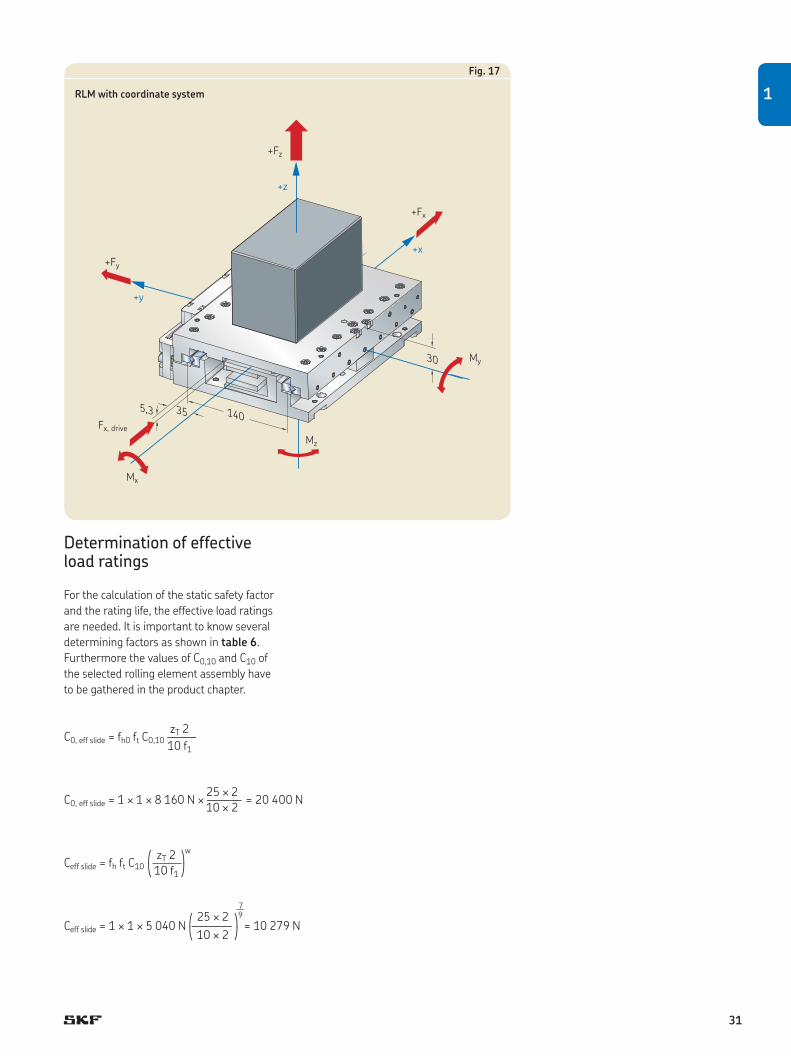
Fig. 17
RLM with coordinate system
Determination of effective load ratings
For the calculation of the static safety factor
and the rating life, the effective load ratings
are needed. It is important to know several
determining factors as shown in table 6.
Furthermore the values of C0,10 and C10 of
the selected rolling element assembly have
to be gathered in the product chapter.
zT 2C0, eff slide = fh0 ft C0,10 ——–
10 f1
q zT 2 wwCeff slide = fh ft C10 ——– < 10 f1 z
25 ¥ 2
C0, eff slide = 1 ¥ 1 ¥ 8 160 N ¥ ——–– = 20 400 N 10 ¥ 2
7 q 25 ¥ 2 w9Ceff slide = 1 ¥ 1 ¥ 5 040 N —––––– = 10 279 N < 10 ¥ 2 z
1
31

Calculation of bearing loads Beside the effective load ratings it is also
necessary to calculate the maximum result-
ing load Fres, max and the equivalent dynamic
mean load Pm of the application. For that, it
is essential to understand the workflow of
the application and where and at what time
the loads are acting. In most cases it is nec-
essary to separate the workflow into load
phases with constant or nearly constant
conditions.
The definition of the general coordinate
system is shown in fig. 17 at the beginning
of this chapter. Fig. 18 shows the lever arms
in x-direction of load phase 6 of the exam-
ple. For an explanation, where to set the
coordinate system, see also chapter 1.9.1.
For each load phase the working loads
have to be summarized to a set of five val-
ues: Fy, Fz, Mx, My, Mz. After that, those five
values and the preload force are transferred
to one load which represents the respective
load phase. The workflow of the application
with its single load phases and the acting
loads including their lever arms of the
example are shown in following systematic
overview († table Load calculation, page 34
and 35). Also the needed formulas and
calculations can be found there. Since the
values for acceleration and deceleration are
equal on forward and backward stroke, it is
here sufficient to calculate Pm only with the
load phases of the forward stroke.
The factor for stroke length has to be
determined with the help of diagram 6,
chapter 1.9.4.
S 150 mm —–– = —————– = 0,91 † fs = 1 Lcage 165,25 mm
The preload force has to be calculated. The
factor for preload fPr depends on the type of
rolling element assembly († chapter
3.1.10).
FPr = fPr Ceff slide
FPr = 0,07 ¥ 10 279 N = 719,5 N
(92,5)
55,037,5
F
Fig. 18
32

Maximum resulting load
The maximum resulting load occurs in load
phase 6.
V
Fres, max = MAX s Fres, j s j=1
Fres, max = 4 362 N
Calculation of the static safety factor
Now for the chosen precision rail guide and
the load phase with the highest resulting
load, the static safety factor s0 can be
calculated.
C0, eff slides0 = —––—–– Fres, max
20 400 Ns0 = —––—––– = 4,68 4 362 N
Equivalent dynamic mean load
For the calculation of the rating life the
equivalent dynamic mean load is needed.
The single values, the needed formula and
the calculations are given in table Load cal-
culations, page 34 and 35. The result is
V
7 Os Pj
p s Sj 7 j=1Pm =
pp JJJJLL = 1 489 N Stot
Rating life calculation
The rating life of precision rail guides
expressed in km, Lns, can now be calculated
using following formula:
q Ceff slide wpLns = c1 100 km —–—– < Pm
z
10 q 10 279 N w 3L10s = 1 ¥ 100 km ¥ —–—––– = 62 640 km < 1 489 N
z
1
33

Load calculations
Workflow divided in load phases
Individual stroke length Sj:Accelleration:Speed:Position at beginning of load phase:
Comment:Forces in Newton [N]Lever arms in Meter [m]Torque loads in Newtonmeter [Nm]
Load phase 1Acceleration, starting from left position
5 mm1 m/s2
Increasing–75 mm
Lever armsx y z
Name of force in x-direction Force Fx
Driving force 40 0,035 –0,0053
Inertia force –40 0 0,075
Name of force in z-direction Force Fz
Construction part –392,4 –0,0375 0
Additional load
0
–392,4
0
–17,93
–1,4
1 841,3
1 841,3
U U
Mx = –O Fy,i zi +O Fz,i yi
i = 1 i = 1
U U
My = O Fx,i zi –O Fz,i xi
i = 1 i = 1
U U
Mz = –O Fx,i yi +O Fy,i xi
i = 1 i = 1
U
Fz = O Fz,i i = 1
U
Fy = O Fy,i
i = 1
q s 2 000 Mx s s 6 000 My s s 6 000 Mz s w
Fres = FPr +sFys +sFzs + s JJJLLL + JJJLLL + JJJLLL s < s B1 s s LT s s LT s z
t s 2 000 Mx s s 6 000 My s s 6 000 Mz s y
P = fs Fres = fss FPr +s Fys +s Fzs + JJJLLL + JJJLLL + JJJLLL s v s B1 s s LT s s LT s b
V 7Os Pj
p s Sj 7
j=1Pm = p JJJJL p
Stot
34

Load phase 2Constant speed
40 mm0 m/s2
0,1 m/s–70 mm
Lever arm is decreasing. As assumption the worst case is chosen for the whole load phase.
Load phase 3Constant speed
60 mm0 m/s2
0,1 m/s0 mm
Lever arm is de creasing, becomes zero and is increasing. As assumption the lever arm is set to zero for the whole load phase.
Load phase 4Constant speed
40 mm0 m/s2
0,1 m/s70 mm
Lever arm is increasing. As assumption the lever arm from the end of this load phase is chosen (worst case).
Load phase 5Deceleration
5 mm–1 m/s2
Decreasing70 mm
Load phase 6Right position at standstill with load
0 mm0 m/s2
0 m/s75 mm
Lever arms Lever arms Lever arms Lever arms Lever armsx x x x y z x y z
Force Fx Force Fx Force Fx Force Fx Force Fx–40 0,035 –0,005340 0 0,075
Force Fz Force Fz Force Fz Force Fz Force Fz–392,4 –0,035 –392,4 0 –392,4 0,035 –392,4 0,035 0 –392,4 0,0375 0
–600 0,0925 0
0 0 0 0 0
–392,4 –392,4 –392,4 –392,4 –992,4
0 0 0 0 0
–13,73 0 13,73 16,95 70,22
0 0 0 1,4 0
1 630,0 1 111,9 1 630,0 1 804,4 4 361,7
1 630,0 1 111,9 1 630,0 1 804,4 4 361,7
7 1 841,3 N10/3 ¥ 5 mm + 1 630 N10/3 ¥ 40 mm + 1 111,9 N10/3 ¥ 60 mm + 1 630 N10/3 ¥ 40 mm + 1 804,4 N10/3 ¥ 5 mmPm = 10/3
7 ——————————————————————————————————————————————————— = 1 489 N
P 5 mm + 40 mm + 60 mm + 40 mm + 5 mm
1
35
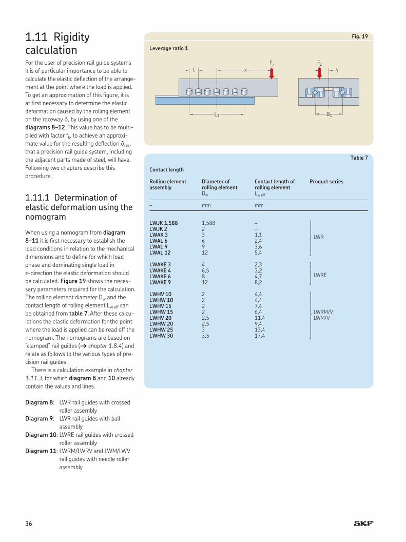
y Fz
B1
x
LT
Fz
t
1.11 Rigidity calculationFor the user of precision rail guide systems
it is of particular importance to be able to
calculate the elastic deflection of the arrange-
ment at the point where the load is applied.
To get an approximation of this figure, it is
at first necessary to determine the elastic
deformation caused by the rolling element
on the raceway d, by using one of the
diagrams 8–12. This value has to be multi-
plied with factor fk, to achieve an approxi-
mate value for the resulting deflection dres,
that a precision rail guide system, including
the adjacent parts made of steel, will have.
Following two chapters describe this
procedure.
1.11.1 Determination of elastic deformation using the nomogram
When using a nomogram from diagram
8–11 it is first necessary to establish the
load conditions in relation to the mechanical
dimensions and to define for which load
phase and dominating single load in
z-direction the elastic deformation should
be calculated. Figure 19 shows the neces-
sary parameters required for the calculation.
The rolling element diameter Dw and the
contact length of rolling element Lw eff can
be obtained from table 7. After these calcu-
lations the elastic deformation for the point
where the load is applied can be read off the
nomogram. The nomograms are based on
”clamped” rail guides († chapter 1.8.4) and
relate as follows to the various types of pre-
cision rail guides.
There is a calculation example in chapter
1.11.3, for which diagram 8 and 10 already
contain the values and lines.
Diagram 8: LWR rail guides with crossed
roller assembly
Diagram 9: LWR rail guides with ball
assembly
Diagram 10: LWRE rail guides with crossed
roller assembly
Diagram 11: LWRM/LWRV and LWM/LWV
rail guides with needle roller
assembly
Table 7
Contact length
Rolling elementassembly
Diameter of rolling element
Contact length of rolling element
Product series
Dw Lw eff
– mm mm
LWJK 1,588 1,588 – r s f LWRssc
LWJK 2 2 –LWAK 3 3 1,1LWAL 6 6 2,4LWAL 9 9 3,6LWAL 12 12 5,4
LWAKE 3 4 2,3 r s f LWRE c
LWAKE 4 6,5 3,2LWAKE 6 8 4,7LWAKE 9 12 8,2
LWHV 10 2 4,4 r s s f LWRM/V LWM/V s s c
LWHW 10 2 4,4LWHV 15 2 7,4LWHW 15 2 6,4LWHV 20 2,5 11,4LWHW 20 2,5 9,4LWHW 25 3 13,4LWHW 30 3,5 17,4
Fig. 19
Leverage ratio 1
36

Preparation
Determination of number of load carrying
rolling elements († chapter 1.8.5 and
1.8.6):
LTzT = — + 1 t
Calculation of average rolling element load
for:
Ball and crossed roller assembly:
FzQ = — zt
Needle roller assembly:
FzQ = —– 2 zt
Calculation of the leverage ratio Rx:
xRx = — t
Calculation of the leverage ratio Ry:
yRy = —– B1
Where
zT = number of load carrying rolling
elements (per cage or per row for
needles)
LT = load carrying length [mm]
t = pitch of rolling elements in cage [mm]
Q = average load per rolling element [N]
Fz = single load in z-direction [N]
x = distance from centre of rolling
element assembly to point of
application of load [mm]
y = distance from centre of rail guide unit
to point of application of load [mm]
B1 = mean distance between the rolling
element assemblies [mm]
Dw = rolling element diameter [mm]
Lw eff = contact length of rolling element [mm]
Identify the elastic deformation in the
nomogram
The values created in section preparation
are now needed to finally identify the elastic
deformation d in the nomogram
(† diagram 8–11).
1
37

Diagram 8
Nomogram of elastic deformation for LWR rail guides with crossed roller assembly
1 2 3 4 6 10 20 40 100 200
zT
d µm500
1 000
500
200
100
50
20
10
5
5
20
0,20,40,60,8
1,01,2
4
6
810
14
20
30
40
50
6 7 8 9 10 15 20 30 40 50
3
Dw69
1215
1825
Q
Ry=y
B1
Rx=xt
38

Diagram 9
Nomogram of elastic deformation for LWR rail guides with ball assembly
5 6 7 8 10 15 20 30 40 50 60 80 100zT
d µm
1 0
005003002001005
0
20
10
4321
2
00,2
0,40,60,8
1,0
1,2
46
10
14
20
30
40
50
60
80
100
6 10 20 40 200 500100
Dw
Q
Ry=yB1
Rx=xt
20
9
63
2
1,5
1215
1
39

Diagram 10
Nomogram of elastic deformation for LWRE rail guides with high capacity crossed roller assembly
1 2 3 4 6 10 20 40 100 200
zT
d µm500
1 000500
2001
005
0
20
10
5
5
20
0,20,60,81,0
1,2
4
6
810
14
20
30
40
50
6 7 8 9 10 15 20 30 40 50
Lw eff
12
108
64
2
Q
Ry=y
B1
Rx=xt
40

Diagram 11
Nomogram of elastic deformation for LWRM / LWRV and LWM / LWV rail guides with needle roller assembly
5 6 7 8 10 15 20 30 40 50 60 80 100zT
d µm
10005002001
005
0
20
10
4321
2
00,2
0,40,6
0,81,0
1,2
46
10
8
14
20
30
40
50
60
80
100
6 10 20 40 200 500100
Lw eff
Q
Ry=yB1
Rx=xt
22
20
18
16
14
12
10
8
1
41

1.11.2 Determination of resulting deflection of a rail guide system
When comparing the measured elastic
deflection of a complete slide system with
the values of the nomograms, the rigidity of
the complete slide system will be found to
be significantly less. This discrepancy is
mainly due to uneven load distribution along
the guide. This happens because inaccura-
cies of form, deviation from parallelism,
improper mounting, etc. and can lead to
variations in the loading of the single rolling
element along the rail guide. By using factor
fk, which is based on the number of load
carrying rolling elements zT and the specific
load on a rolling element k, attention is paid
to this circumstances. The relevant values of
fk for LWRE rail guides with crossed roller
assembly and LWRM/LWRV rail guides or
LWM/LWV rail guides with needle roller
assembly can be obtained from diagram 12.
When calculating the elastic deflection of an
LWR rail guide, the correction factor fk has to
be obtained from diagram 13. When using
LWR rail guides with ball assembly the cal-
culated values conform to the measure-
ments and no factor fk is needed.
For the calculation example in chapter
1.11.3, both diagrams already contain the
values and lines.
Determination of the specific load per rolling
element:
for LWR crossed roller assembly:
Fzk = ——— zT Dw
2
for LWRE crossed roller assembly:
Fzk = ————— zT Dw Lw eff
for needle roller assembly:
Fzk = —————— 2 zT Dw Lw eff
Diagram 12
Correction factor fk for LWRE, LWRM/LWRV or LWM/LWV rail guides
Diagram 13
Correction factor fk for LWR rail guides
1,0
1,4
1,2
2,0
1,91,8
1,6
2
2,42,32,2
fk
zT
5 6 7 8 10 15 25 30 40 50 60 80 100
k = 1
2
5
10
20
5070
100
6,0
1,0
1,5
2,0
3,0
4,0
5,0
fk
5 6 7 8 10 15 25 30 40 50 60 80 100
10 12 14 16 20 30 40 60 80 100
zT
120 160 200
k = 1
2
5
10
20
5070100
Needle roller assembly
LWRE crossed roller assembly
Number of load carrying rolling elements
Number of load carrying rolling elements
where
k = specific load per rolling element
[N/mm2]
Fz = single load in z-direction [N]
zT = number of load carrying rolling
elements (per cage or per row for
needles)
Dw = rolling element diameter [mm]
Lw eff = contact length of rolling element [mm]
42

Calculation of resulting deflection:
dres = fk d
where
dres = resulting deflection [µm]
d = elastic deformation (determined in
nomogram) [µm]
fk = correction factor
1.11.3 Calculation example for the resulting deflection
The standard SKF GCL 6400 slide is loaded
in an extended position with a load of 1 000 N
as shown in table 8. What is the resulting
deflection of the LWR6 rail guide at the point
where the load is applied in this case? How
great would this have been for a LWRE6 rail
guide?
Following values have to be determined
(† table 8).
Table 8
Calculation example for the resulting deflection
Parameter Unit LWR LWRE
Load carrying length LT mm 252 253Pitch of rolling element assembly t mm 9 11Number of load carrying rolling elements zT 29 24Leverage ratio Rx = x/t 26,7 21,8Leverage ratio Ry = y/B1 0,44 0,44Rolling element diameter Dw mm 6 8Contact length of rolling element Lw eff mm 2,4 4,7Average load per rolling element Q N 34,5 41,7Elastic deformation d (determined in nomogram) µm 22,5 13Specific load per rolling element k N/mm2 0,96 1,1Correction factor fk 1,99 2,9Resulting deflection dres µm 45 38
y = 20
Fz
B1 = 45
x = 240
LT max = 260
Fz = 1 000 N
1
43

1.12 Technical data of precision rail guides with slide coating1.12.1 Surface pressure
To achieve a reasonable value for the con-
tact deformation, the surface pressure of
plain bearings or guidings is normally in the
region of 0,2 to 1 N/mm2. Diagram 14
shows the surface deformation of Turcite-B
rail guides expressed in relation to surface
pressure. In case of overload, up to
6 N/mm2, the contact deformation rises to
5 µm but recovers to the original dimension
when the load is relieved.
1.12.2 Wear LWRPM / LWRPV rail guides are character-
ised by their high resistance to wear. The
ground surface of the LWRPV guides is
matched to suit the Turcite-B so that the
degree of wear is kept to a minimum. Even
a certain amount of contamination can be
tolerated without affecting the sliding
qualities since the slide material is capable
of allowing small particles to become
embedded in the surface.
For optimum performance, however, lubri-
cation of the LWRPM / LWRPV rail guides is
recommended. As seen in diagram 15, the
oil-lubricated guide (curve 1) shows less
wear along the length of travel in comparison
with the non-lubricated guide (curve 2). The
values indicated are for an average surface
pressure of 0,4 N/mm2.
1.12.3 Frictional properties Due to the favourable frictional qualities of
Turcite-B, the running speed of a dry sliding
rail guide has relatively little effect on the
coefficient of friction, and ‘stickslip’ is
virtually eliminated.
Diagram 16 illustrates the relationship
between the coefficient of friction for
LWRPM / LWRPV rail guides as a function
of sliding speed. Curve 1 applies to an oil-
lubricated guide, and curve 2 applies to a
non-lubricated installation. The degree of
friction is seen to fall during a ‘smoothing’
phase and then remains relatively constant.
The values indicated are based on an aver-
age surface pressure of 0,2 N/mm2.
Diagram 14
Contact deformation in relation to suface pressure
Diagram 15
Wear in relation to length of travel
Diagram 16
Coefficient of friction as a function of sliding speed
0,5
1,5
2,5
3,5
3
2
1
4
01,00 1,250,50 0,750,250 1,50 1,75 2,00
Surface pressure [N/mm2]
Contact deformation, [µm]
20
10
30
040200 60
Travel [km]
Wear [µm]
0,28
0,24
0,20
0,16
0,12
0,08
0,04
02501005010 25421 6 5 000
10 0002 5001 000500
Speed [mm/min]
Coefficient of friction
1 (lubricated)
1 (lubricated)
2 (dry)
2 (dry)
44

Diagram 17 shows the coefficient
of friction for an oil-lubricated LWRPM /
LWRPV rail guide in relation to the surface
pressure. Here it will be seen that the coef-
ficient of friction for low load conditions is
relatively high, but when the surface pres-
sure reaches 0,2 N/mm2, the coefficient falls
to a minimum and remains constant.
1.12.4 Temperature range The operating temperature of a linear plain
bearing should lie between the limits of
–40°C and +80°C. Higher temperatures
tend to reduce the pressure resistance. In
many cases, the dissipation of heat can be
enhanced through the use of lubricating oil.
1.12.5 Chemical and humidity resistance
Turcite-B possesses excellent chemical
resistance. Moisture absorbency amounts to
a maximum of 0,01 percent and has no sig-
nificant dimensional effect. Sliding surfaces
of Turcite-B are consequently highly resist-
ant to cool conditions and the effect of lubri-
cating oils.
Diagram 17
Coefficient of friction as a function of surface pressure
0,10
0,08
0,06
0,04
0,02
00,40,30,20,10
Surface pressure [N/mm2]
Coefficient of friction
(lubricated)
1
45

Table 9
Legend
B1 mean distance between the rolling element assemblies [mm]C dynamic load rating [N] C0 static load rating [N]C10 basic dynamic load rating of a cage with 10 rolling elements (balls, rollers) or with 2 rows of 10 needles under load [N] C0,10 basic static load rating of a cage with 10 rolling elements (balls, rollers) or with 2 rows of 10 needles under load [N]Ceff effective dynamic load rating of one cage [N]Ceff slide effective dynamic load rating of a slide [N]C0, eff slide effective static load rating of a slide [N] c1 factor for reliabilityd elastic deformation (determined in nomogram) [µm]dres resulting deflection [µm]EG length of lead in radius on each side [mm]f1 factor for load directionfh factor for hardness, dynamicfh0 factor for hardness, staticfk correction factorfPr factor for preload [%]fs, fs,j factor for stroke lengthft factor for operating temperatureFPr preload force [N]Fres resulting load [N]Fres max maximum resulting load [N]Fx,i, Fy,i, Fz,i single loads in x-, y- or z-direction that act simultaneously on the rail guide system [N]Fy, Fz summarized force (load) in y- or z-direction [N]k specific load per rolling element [N/mm2]L10h basic rating life [h] L10s basic rating life [km] Lns modified basic rating life [km] Lcage length of rolling element assembly [mm]Lcage, max maximum length of rolling element assembly, if length of rail and stroke are predefined [mm]Linstall length of the complete installation [mm]Lrail length of the rail [mm]Lrail, min minimum length of the rail, if length of cage and stroke are predefined [mm]Lrail, long length of the long rail [mm]Lrail, long, min minimum length of the long rail, if length of cage and stroke are predefined [mm]Lrail, short length of the short rail in an overrunning system [mm]LT load carrying length [mm]Lw eff contact length of rolling element [mm]Mx, My, Mz summarized torque loads in x-, y- or z-direction [Nm]n stroke frequency [double strokes/min]p life exponent; p = 3 for balls, p = 10/3 for rollersP equivalent dynamic load [N] Pm equivalent dynamic mean load [N] P0 maximum static load [N]Q average load per rolling element [N]Rx leverage ratio in x-directionRy leverage ratio in y-directions0 static safety factorS intended stroke length [mm]Sj individual stroke length [mm] Stot total stroke length [mm] xi, yi, zi, lever arms that are related to the single loads [m] w rolling element exponent; w = 0,7 for balls, w = 7/9 for rollersz number of rolling elements (per cage or per row for needles)zT number of load carrying rolling elements (per cage or per row for needles)
Dimensions from product data:A Width of precision rail guide [mm]L thickness of end piece [mm]L1 thickness of end piece with wiper [mm]t pitch of rolling elements in cage [mm] t1, t2 distance of outer rolling element to the end of the cage [mm] t3 length of anti-creeping system [mm] J1 length between end of rail and first mounting hole [mm]
Indizesi counter for single loads in x-, y- or z-direction that act simultaneouslyU amount of loads that act simultaneouslyj counter for load phasesV amount of load phases
1.13 Legend
46

2 Product data
2.1 LWR / LWRB
Rail guidesLWR and LWRB rail guides are well-proven,
limited-travel linear guides used in numer-
ous applications. They can be used with
crossed roller assemblies or ball assemblies,
depending on the respective application.
LWR rail guides with crossed roller assem-
blies are preferred for high load carrying
capacity and good rigidity behaviour. LWRB
rail guides with ball assembly can be used
where loads are light and/or easy running is
required. The small cross-section is ideal for
applications with limited space.
Rolling element assembliesLWJK ball assemblies, which are used
together with LWRB rails, are provided with
a ball-retaining plastic cage. These are
available for sizes 1 and 2.
LWAK crossed roller assemblies comprise
a plastic cage with retained cylindrical roll-
ers, available as standard for size 3.
LWAL crossed roller assemblies, consist-
ing of an aluminium cage with retained roll-
ers, are available in sizes 6 to 12.
End pieces End pieces prevent drift of the cage away
from the loaded zone. Available types are
LWERA, LWERB as standard end pieces, and
LWERC as end pieces with wipers. All end
pieces are supplied with appropriate mount-
ing screws.
Ordering example:
4x LWR 9600
2x LWAL 9x25
8x LWERA 9
1
47

G1
G
N
A1
J2
BN1
A
DwJ3
A
J3Dw G1
G
N
A1
J2
BN1
L
J1 J1J
G2
G3
LWR precision rail guides
LWRB 1 8,5 4 3,9 1,588 0,11 10 5 5 1,8 M2 1,65 3 1,4 1,9 M1,6 2 LWRB 2 12 6 5,5 2 0,23 15 7,5 7,5 2,5 M3 2,55 4,4 2 2,7 M2,5 3
LWR 3 18 8 8,2 3 0,45 25 12,5 12,5 3,5 M4 3,3 6 3,2 4 M3 6LWR 6 31 15 13,9 6 1,46 50 25 20 6 M6 5,2 9,5 5,2 7 M5 9LWR 9 44 22 19,7 9 3,14 100 50 20 9 M8 6,8 10,5 6,2 10 M6 9LWR 12 58 28 25,9 12 5,23 100 50 30 12 M10 8,5 13,5 8,2 13 M8 12
Designation1) Dimensions Weight Mounting holes End face holes
A B A1 Dw J J1 J1 min J2 G G1 N N1 J3 G2 G3
– mm kg/m mm – mm mm – mm
Designation1) Dimensions Weight Mounting holes End face holes
A B A1 Dw J J1 J1 min J2 G G1 N N1 J3 G2 G3
– mm kg/m mm – mm mm – mm
1) Sizes LWR 15, 18 and 24 are available on request.
LWR LWRB
48

l l l l l L L L L 150 l l l l l l l L L 200
l l l l l l l L l L l 400 l L l l l l l l l l L L L L 1 200
l l l l L L L L L 1 500L L L L L L L L L L L L L 1 500
Available lengths1) Maximum20 30 40 45 50 60 70 75 80 90 100 105 120 135 150 rail lengthL
mm mm
Available lengths1) Maximum rail length50 75 100 125 150 175 200 225 250 275 300 350 400 450 500 550 600 650 700 800 900 1 000
L
mm mm
LWR rail guides in kit packaging
Designation Load ratings1) Stroke2) Type of rail Type of cage Type of end piecedyn. stat. standard max 4 pieces 2 pieces 8 pieces
C C0
– N mm – –
LWR 3050 – Kit 999 1 120 26 33 LWR 3050 LWAK 3x7 LWERA 3LWR 3075 – Kit 1 422 1 760 36 50 LWR 3075 LWAK 3x11 LWERA 3LWR 3100 – Kit 1 811 2 400 46 67 LWR 3100 LWAK 3x15 LWERA 3LWR 3125 – Kit 2 088 2 880 66 83 LWR 3125 LWAK 3x18 LWERA 3LWR 3150 – Kit 2 442 3 520 76 100 LWR 3150 LWAK 3x22 LWERA 3LWR 3175 – Kit 2 781 4 160 86 117 LWR 3175 LWAK 3x26 LWERA 3LWR 3200 – Kit 3 110 4 800 96 133 LWR 3200 LWAK 3x30 LWERA 3
LWR 6100 - Kit 4 915 5 440 50 67 LWR 6100 LWAL 6x8 LWERA 6LWR 6150 - Kit 6 744 8 160 78 100 LWR 6150 LWAL 6x12 LWERA 6LWR 6200 - Kit 8 441 10 880 106 133 LWR 6200 LWAL 6x16 LWERA 6LWR 6250 - Kit 10 045 13 600 134 167 LWR 6250 LWAL 6x20 LWERA 6LWR 6300 – Kit 11 955 17 000 144 200 LWR 6300 LWAL 6x25 LWERA 6LWR 6350 – Kit 13 422 19 720 172 233 LWR 6350 LWAL 6x29 LWERA 6LWR 6400 – Kit 14 846 22 440 200 267 LWR 6400 LWAL 6x33 LWERA 6
1) Load ratings are given for a kit of 4 rails and 2 cages in clamped arrangement.2) Cage length is adjustable but must not be shorter than 2/3 of the total rail length.
1) Other rail lengths are available on request but new J1 dimension has to be calculated as described in chapter 3.1.7, Calculation of J1 dimension.l) Prompt deliveryL) Delivery time on request
2
49

Ball and crossed roller assemblies
Designation Dimensions Load ratings for 10 rolling elements
Maximum cage length
Appropriate rail guide
dynamic static Dw U U1 t t1 C10 C0 10
– mm N Balls/Rollers –
LWJK 1,588 1,588 3,5 0,5 2,2 1 410 580 38 LWRB 1 LWJK 2 2 5 0,75 3,9 1,5 640 720 25 LWRB 2
LWAK 3 3 7,5 1 5 3,5 1 320 1 600 200 LWR 3 LWAL 6 6 14,8 2,7 9 6 5 850 6 800 166 LWR 6 LWAL 9 9 20 4 14 9,4 17 000 18 300 106 LWR 9 LWAL 12 12 25 5 18 12 30 000 30 500 83 LWR 12
U
U1
tt1
Dw Dw
U
U1
tt1
U
U1
tt1
Dw
LWJK LWAK LWAL
50
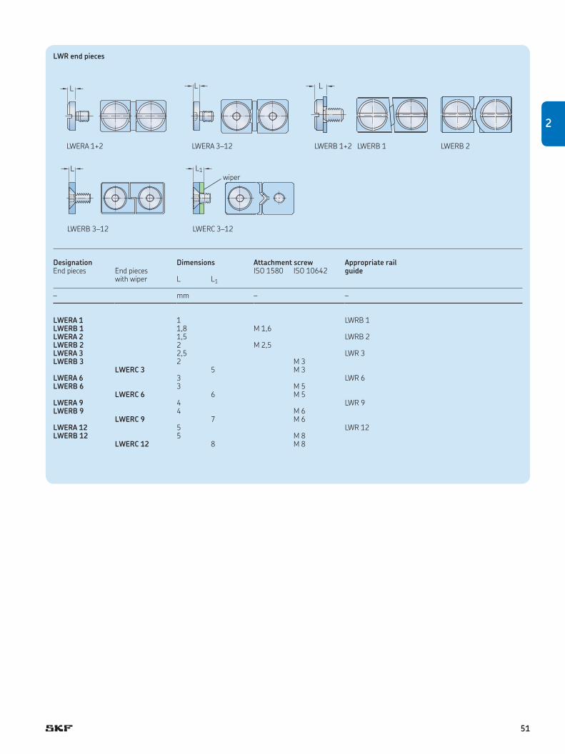
LWR end pieces
Designation Dimensions Attachment screw Appropriate rail guideEnd pieces End pieces
with wiperISO 1580 ISO 10642
L L1
– mm – –
LWERA 1 1 LWRB 1 LWERB 1 1,8 M 1,6 LWERA 2 1,5 LWRB 2 LWERB 2 2 M 2,5 LWERA 3 2,5 LWR 3 LWERB 3 2 M 3
LWERC 3 5 M 3 LWERA 6 3 LWR 6 LWERB 6 3 M 5
LWERC 6 6 M 5 LWERA 9 4 LWR 9 LWERB 9 4 M 6
LWERC 9 7 M 6 LWERA 12 5 LWR 12 LWERB 12 5 M 8
LWERC 12 8 M 8
L
L
L L
LWERA 1+2 LWERA 3–12 LWERB 1+2 LWERB 1 LWERB 2
LWERB 3–12 LWERC 3–12
L1
wiper
51
2

2.2 LWRE
Rail guides LWRE rail guides are a logical development
of the proven LWR rail guides. In addition
to the familiar characteristics of the LWR
series, the LWRE rail guides offer the advan-
tages of fivefold load ratings and a doubling
of the rigidity. This means that for the same
load capacity, a 50% reduction in bearing
size compared with the standard LWR rail
guide is possible († fig. 1). Alternatively,
with the same outer dimensions, greatly
increased static safety and lifetime results.
The improvements are achieved through
optimized internal geometry in conjunction
with larger roller diameters. Furthermore,
LWRE rail guides utilise the whole roller
length so that no tilting moment or edge
stresses can occur († fig. 2). The mounting
and attachment dimensions of the LWRE rail
guides conform to those of all the SKF Mod-
ular Range rail guides included in this
catalogue.
Rolling element assembliesLWAKE crossed roller cages consist of
individual plastic elements. In LWAKE 3, 6
and 9 cages, these elements are assembled
using a ‘snap in’ technique, whereby each
element can be rotated manually through an
angle of 90° († fig. 3). The load rating and
rigidity can be increased by turning the
rollers in the direction of the main load. As
standard, the orientation of the rollers is
alternating. The cage retains the rollers and
at the same time almost fills the free space
between the rails, thus providing good
protection against ingress of dirt. LWAKE 4
cages consist of roller segments fitted
together to the customer’s specific length
requirements. Individual rotating is not
possible for size 4.
End piecesEnd pieces prevent drift of the cage away
from the loaded zone. LWERE end pieces
are generally used for horizontal and vertical
applications. An end piece with wiper,
LWEREC, is available. All end pieces are
supplied with appropriate mounting screws.
Ordering example:
4x LWRE 6200
2x LWAKE 6x13
8x LWERE 6
52

Fig. 1
Fig. 3
Fig. 2
LWRE 6
LWR 12P = 4 000
Dw =
6
Nmm
2
M = Q x e
e = 1,2
Q
Q
M
L w eff =
2,4
L w eff =
4,7
Q
Q
M
M = 0
e =
0
P = 4 000Nmm
2
Dw =
8
LWRE 6
LWR 6
53
2

LWRE precision rail guides
A
DwJ3
G
N
A1
J2
BN1
G1
L
J1 J1J
G2
G3
LWRE 2211 22 11 10,7 4 0,8 40 20 15 4,5 M 5 4,3 7,5 4,1 6 M 3 6
LWRE 3 18 8 8,7 4 0,44 25 12,5 12,5 3,5 M 4 3,3 6 3,2 4 M 3 6 LWRE 4 25 12 12 6,5 0,93 25 12,5 12,5 5 M 4 3,3 6 3,2 5 M 3 6 LWRE 6 31 15 15,2 8 1,44 50 25 20 6 M 6 5,2 9,5 5,2 6,75 M 5 9 LWRE 9 44 22 21,7 12 3,09 100 50 20 9 M 8 6,8 10,5 6,2 9,75 M 6 9
Designation Dimensions Weight Mounting holes End face holes
A B A1 Dw J J1 J1 min J2 G G1 N N1 J3 G2 G3
– mm kg/m mm – mm mm – mm
Designation Dimensions Weight Mounting holes End face holes
A B A1 Dw J J1 J1 min J2 G G1 N N1 J3 G2 G3
– mm kg/m mm – mm mm – mm
54

L L L L L L L L L 500
l l l l l l l L L L L 400 l l l l l l L L L L L 700
l l l l l L l L L L L L L 1 200l l l l l L L L L 1 500
Available lengths1) Maximum80 120 160 200 240 280 320 360 400 rail lengthL
mm mm
Available lengths1) Maximum rail length50 75 100 125 150 175 200 225 250 275 300 350 400 450 500 550 600 650 700 800 900 1 000
L
mm mm
1) Other rail lengths are available on request but new J1 dimension has to be calculated as described in chapter 3.1.7, Calculation of J1 dimension.l) Prompt deliveryL) Delivery time on request
LWRE rail guides in kit packaging
Designation Load ratings1) Stroke2) Type of rail Type of cage Type of end piecedyn. stat. standard max 4 pieces 2 pieces 8 pieces
C C0
– N mm – –
LWRE 3050 – Kit 4 230 5 100 25 33 LWRE 3050 LWAKE 3x6 LWERE 3LWRE 3075 – Kit 5 803 7 650 38 50 LWRE 3075 LWAKE 3x9 LWERE 3LWRE 3100 – Kit 7 263 10 200 50 67 LWRE 3100 LWAKE 3x12 LWERE 3LWRE 3125 – Kit 8 644 12 750 63 83 LWRE 3125 LWAKE 3x15 LWERE 3LWRE 3150 – Kit 9 964 15 300 75 100 LWRE 3150 LWAKE 3x18 LWERE 3LWRE 3175 – Kit 11 238 17 850 88 117 LWRE 3175 LWAKE 3x21 LWERE 3LWRE 3200 – Kit 12 471 20 400 100 133 LWRE 3200 LWAKE 3x24 LWERE 3
LWRE 4100 – Kit 17 300 20 800 39 67 LWRE 4100 LWAKE 4x10 LWERE 4LWRE 4150 – Kit 23 735 31 200 62 100 LWRE 4150 LWAKE 4x15 LWERE 4LWRE 4200 – Kit 28 541 39 520 95 133 LWRE 4200 LWAKE 4x19 LWERE 4LWRE 4250 – Kit 34 246 49 920 118 167 LWRE 4250 LWAKE 4x24 LWERE 4LWRE 4300 – Kit 38 622 58 240 152 200 LWRE 4300 LWAKE 4x28 LWERE 4LWRE 4350 – Kit 43 902 68 640 169 233 LWRE 4350 LWAKE 4x33 LWERE 4LWRE 4400 – Kit 49 009 79 040 192 267 LWRE 4400 LWAKE 4x38 LWERE 4
LWRE 6100 – Kit 25 743 27 300 46 67 LWRE 6100 LWAKE 6x7 LWERE 6LWRE 6150 – Kit 34 000 39 000 80 100 LWRE 6150 LWAKE 6x10 LWERE 6LWRE 6200 – Kit 44 204 54 600 92 133 LWRE 6200 LWAKE 6x14 LWERE 6LWRE 6250 – Kit 51 431 66 300 126 167 LWRE 6250 LWAKE 6x17 LWERE 6LWRE 6300 – Kit 58 382 78 000 160 200 LWRE 6300 LWAKE 6x20 LWERE 6LWRE 6350 – Kit 67 304 93 600 172 233 LWRE 6350 LWAKE 6x24 LWERE 6LWRE 6400 – Kit 73 781 105 300 206 267 LWRE 6400 LWAKE 6x27 LWERE 6
1) Load ratings are given for a kit of 4 rails and 2 cages in clamped arrangement.2) Cage length is adjustable but must not be shorter than 2/3 of the total rail length.
2
55

Crossed roller assemblies
Designation Dimensions Load ratings for 10 rolling elements
Maximum cage length1)
Appropriate rail guide
dynamic static Dw t t1 t2 C10 C0 10
– mm N mm –
LWAKE 3 4 6,25 2,65 3,6 6 300 8 500 1 000 LWRE 3, LWRE 2211 LWAKE 4 6,5 8 4,3 4,3 17 300 20 800 1 000 LWRE 4 LWAKE 6 8 11 5 6 34 000 39 000 1 000 LWRE 6 LWAKE 9 12 16 7,35 8,65 78 000 78 000 1 000 LWRE 9
Dw
tt1 t2Dw
t2tt1
LWAKE 3, 6, 9 LWAKE 4
LWRE end pieces
Designation Dimensions Attachment screw Appropriate rail guideEnd pieces End pieces
with wiperISO 10642
L L1
– mm – –
LWERE 3 2 M 3 LWRE 3, LWRE 2211LWEREC 3 4 M 3 LWRE 3, LWRE 2212
LWERE 4 4 M 3 (DIN 7984) LWRE 4LWERE 6 3 M 5 LWRE 6
LWEREC 6 5 M 5 LWRE 6LWERE 9 3 M 6 LWRE 9
LWEREC 9 6 M 6 LWRE 9
L L1 L
LWERE 3, 6, 9 LWEREC 3, 6, 9 LWERE 4
wiper
1) Longer cages are available on request.
56

2.3 LWRE ACS
Rail guidesLWRE ACS rail guides are identical to LWRE
rail guides, but designed for use with anti-
creeping LWAKE ACS cages. The non-slip
effect is achieved through a patented control
gear attached to the cage, which is in mesh
between the LWRE ACS rails during opera-
tion, thus retaining the cage in its defined
position. As standard, the rails are prepared
for maximum stroke († chapter 1.4).
Rolling element assembliesIn principle, LWAKE ACS are the same as
LWAKE cages, whereby LWAKE ACS crossed
roller cages incorporate an additional control
gear located at the centre of the cage. The
load carrying capacity of LWAKE ACS cages
is also identical with that of LWAKE standard
cages, assuming that they comprise an
identical number of rollers. However, con-
sider that due to their additional control
gear, LWAKE ACS cages are longer than the
corresponding LWAKE cages, even if the
number of rollers is identical. Overrunning
cages should only be used after consulting
SKF.
End piecesEnd pieces are generally not needed, but for
production reasons, the tapped holes on the
rail’s end face are standard and end pieces
can be mounted. LWERE end pieces are
generally used for horizontal and vertical
applications. An end piece with wiper,
LWEREC, is available. All end pieces are
supplied with appropriate mounting screws.
The end pieces for LWRE rail guides are
also suitable for LWRE ACS rail guides.
Ordering example for rail with maximum
stroke:
4x LWRE 6200 ACS
2x LWAKE 6x12 ACS
8x LWERE 6
57
2

LWRE ACS precision rail guides
A
DwJ3
G
N
A1
J2
BN1
G1
L
J1 J1J
G2
G3
LWRE 2211 ACS 22 11 10,7 4 0,8 40 20 15 4,5 M 5 4,3 7,5 4,1 6 M 3 6
LWRE 3 ACS 18 8 8,7 4 0,44 25 12,5 12,5 3,5 M 4 3,3 6 3,2 4 M 3 6LWRE 4 ACS 25 12 12 6,5 0,92 25 12,5 12,5 5 M 4 3,3 6 3,2 5 M 3 6LWRE 6 ACS 31 15 15,2 8 1,44 50 25 20 6 M 6 5,2 9,5 5,2 6,75 M 5 9LWRE 9 ACS 44 22 21,7 12 3,08 100 50 20 9 M 8 6,8 10,5 6,2 9,75 M 6 9
Designation Dimensions Weight Mounting holes End face holes
A B A1 Dw J J1 J1 min J2 G G1 N N1 J3 G2 G3
– mm kg/m mm – mm mm – mm
Designation Dimensions Weight Mounting holes End face holes
A B A1 Dw J J1 J1 min J2 G G1 N N1 J3 G2 G3
– mm kg/m mm – mm mm – mm
58

L L L L L L L L L 500
l l l l l l l L L L L 400 L L L L L L L L L L L 700
l l l L l L l L l L L L L 1 200L L L L L L L L L 1 500
Available lengths1) Maximum80 120 160 200 240 280 320 360 400 rail lengthL
mm mm
Available lengths1) Maximum rail length50 75 100 125 150 175 200 225 250 275 300 350 400 450 500 550 600 650 700 800 900 1 000
L
mm mm
1) Other rail lengths are available on request but new J1 dimension has to be calculated as described in chapter 3.1.7, Calculation of J1 dimension.l) Prompt deliveryL) Delivery time on request
LWRE ACS rail guides in kit packaging
Designation Load ratings1) Stroke2) Type of rail Type of cage Type of end piecedyn. stat. standard max 4 pieces 2 pieces 8 pieces
C C0
– N mm – –
LWRE 3050 ACS – Kit 3 465 4 250 20 33 LWRE 3050 ACS LWAKE 3 x 5 ACS LWERE 3LWRE 3075 ACS – Kit 5 294 6 800 30 50 LWRE 3075 ACS LWAKE 3 x 6 ACS LWERE 3LWRE 3100 ACS – Kit 6 300 8 500 45 67 LWRE 3100 ACS LWAKE 3 x 10 ACS LWERE 3LWRE 3125 ACS – Kit 7 731 11 050 62 83 LWRE 3125 ACS LWAKE 3 x 13 ACS LWERE 3LWRE 3150 ACS – Kit 9 090 13 600 79 100 LWRE 3150 ACS LWAKE 3 x 16 ACS LWERE 3LWRE 3175 ACS – Kit 9 964 15 300 94 117 LWRE 3175 ACS LWAKE 3 x 18 ACS LWERE 3LWRE 3200 ACS – Kit 11 653 18 700 100 133 LWRE 3200 ACS LWAKE 3 x 22 ACS LWERE 3
LWRE 4100 ACS – Kit 14 536 16 640 40 67 LWRE 4100 ACS LWAKE 4x8 ACS LWERE 4LWRE 4150 ACS – Kit 19 944 24 960 79 100 LWRE 4150 ACS LWAKE 4x12 ACS LWERE 4LWRE 4200 ACS – Kit 26 170 35 360 96 133 LWRE 4200 ACS LWAKE 4x17 ACS LWERE 4LWRE 4250 ACS – Kit 30 859 43 680 129 167 LWRE 4250 ACS LWAKE 4x21 ACS LWERE 4LWRE 4300 ACS – Kit 36 452 54080 152 200 LWRE 4300 ACS LWAKE 4x26 ACS LWERE 4LWRE 4350 ACS – Kit 41 813 64 480 175 233 LWRE 4350 ACS LWAKE 4x31 ACS LWERE 4LWRE 4400 ACS – Kit 45 964 72 800 203 267 LWRE 4400 ACS LWAKE 4x35 ACS LWERE 4
LWRE 6100 ACS – Kit 22 826 23 400 37 67 LWRE 6100 ACS LWAKE 6 x 6 ACS LWERE 6LWRE 6150 ACS – Kit 31 318 35 100 71 100 LWRE 6150 ACS LWAKE 6 x 9 ACS LWERE 6LWRE 6200 ACS – Kit 39 196 46 800 105 133 LWRE 6200 ACS LWAKE 6 x 12 ACS LWERE 6LWRE 6250 ACS – Kit 49 056 62 400 117 167 LWRE 6250 ACS LWAKE 6 x 16 ACS LWERE 6LWRE 6300 ACS – Kit 56 093 74 100 151 200 LWRE 6300 ACS LWAKE 6 x 19 ACS LWERE 6LWRE 6350 ACS – Kit 65 107 89 700 163 233 LWRE 6350 ACS LWAKE 6 x 23 ACS LWERE 6LWRE 6400 ACS – Kit 71 640 101 400 197 267 LWRE 6400 ACS LWAKE 6 x 26 ACS LWERE 6
1) Load ratings are given for a kit of 4 rails and 2 cages in clamped arrangement.2) Cage length is adjustable but must not be shorter than 2/3 of the total rail length.
2
59

Crossed roller assemblies
Designation Dimensions Load ratings for 10 rolling elements
Maximum cage length1)
Appropriate rail guide
dynamic static Dw t t1 t2 t3 C10 C0 10
– mm N mm –
LWAKE 3 ACS 4 6,25 2,65 3,6 9 6 300 8 500 1 000 LWRE 3 ACS, LWRE 2211 ACS LWAKE 4 ACS 6,5 8 4,3 4,3 17 17 300 20 800 1 000 LWRE 4 ACS LWAKE 6 ACS 8 11 5 6 15 34 000 39 000 1 000 LWRE 6 ACS LWAKE 9 ACS 12 16 7,35 8,65 21,5 78 000 78 000 1 000 LWRE 9 ACS
Dw
tt1 t3t2Dw
tt1 t3 t2
LWAKE 3, 6, 9 ACS LWAKE 4 ACS
LWRE ACS end pieces
Designation Dimensions Attachment screw Appropriate rail guideEnd pieces End pieces
with wiperISO 10642
L L1
– mm – –
LWERE 3 2 M 3 LWRE 3, LWRE 2211LWEREC 3 4 M 3 LWRE 3, LWRE 2212
LWERE 4 4 M 3 (DIN 7984) LWRE 4LWERE 6 3 M 5 LWRE 6
LWEREC 6 5 M 5 LWRE 6LWERE 9 3 M 6 LWRE 9
LWEREC 9 6 M 6 LWRE 9
L L1 L
LWERE 3, 6, 9 LWEREC 3, 6, 9 LWERE 4
wiper
1) Longer cages are available on request.
60

Rolling element assembliesIn principle, LWAKE ACSM cages are the
same as LWAKE cages, whereby LWAKE
ACSM crossed roller cages incorporate an
additional control gear made of brass located
at the centre of the cage. When defining the
cage length, the additional length of the
control gear should be considered. Over-
running cages should only be used after
consulting SKF. The given load capacities are
already calculated for stainless steel rails,
which means factor fh remains at one for
calculation of the lifetime.
End piecesGenerally, the LWRE ACSM rail guides are
not designed for use with end pieces. How-
ever, if required, this must be stated sepa-
rately in the ordering code of the rail (Option
E7). The end pieces for LWRE rail guides are
also suitable for LWRE ACSM rail guides.
Ordering example:
4x LWRE 3150 ACSM
2x LWAKE 3x16 ACSM
Rail guidesThe refinement of our own ACS solution
became the LWRE and LWRB ACSM rail
guide version. LWRE and LWRB ACSM rail
guides have the same outer dimensions as
those without ACSM, but are designed for
use with anti-creeping LWAKE ACSM cages.
This cage, with an involute-toothed control
gear made of brass and involute teeth
directly machined into the rail, prevent
cage-creeping very effectively and are espe-
cially suited for applications with high accel-
erations († chapter 1.4). These rails are
made of stainless steel as standard.
2.4 LWRE / LWRB ACSM
61
2

LWRE ACSM precision rail guides
A
DwJ3
G
N
A1
J2
BN1
G1
L
J1 J1J
G2
G3
LWRE 2211 ACSM 22 11 10,7 4 0,79 40 20 15 4,5 M 5 4,3 7,5 4,1 6 M 3 6
LWRB 2 ACSM 12 6 5,5 2 0,23 15 7,5 7,5 2,5 M3 2,55 4,4 2 2,7 M2,5 3 LWRE 3 ACSM 18 8 8,7 4 0,44 25 12,5 12,5 3,5 M 4 3,3 6 3,2 4 M 3 6 LWRE 4 ACSM 25 12 12 6,5 0,91 25 12,5 12,5 5 M 4 3,3 6 3,2 5 M 3 6 LWRE 6 ACSM 31 15 15,2 8 1,42 50 25 20 6 M 6 5,2 9,5 5,2 6,75 M 5 9 LWRE 9 ACSM 44 22 21,7 12 3,05 100 50 20 9 M 8 6,8 10,5 6,2 9,75 M 6 9
Designation Dimensions Weight Mounting holes End face holes1)
A B A1 Dw J J1 J1 min J2 G G1 N N1 J3 G2 G3
– mm kg/m mm – mm mm – mm
Designation Dimensions Weight Mounting holes End face holes1)
A B A1 Dw J J1 J1 min J2 G G1 N N1 J3 G2 G3
– mm kg/m mm – mm mm – mm
1) Standard is without end face holes; Option E7 means with end face holes (blue lines)
62

L L L L L L L L L 400
L L L L L L L L L 200 l l l l l l l l l l l l l 400
L L L L L L 400l l l l l l l 400
L L l 400
Available lengths1) Maximum80 120 160 200 240 280 320 360 400 rail lengthL
mm mm
Available lengths1) Maximum rail length30 45 50 60 75 90 100 105 120 125 135 150 175 200 225 250 275 300 350 400
L
mm mm
1) Other rail lengths are available on request but new J1 dimension has to be calculated as described in chapter 3.1.7, Calculation of J1 dimension.l) Prompt deliveryL) Delivery time on request
LWRE ACSM rail guides in kit packaging
Designation Load ratings1), 2) Stroke3) Type of rail Type of cage dyn. stat. standard max 4 pieces 2 pieces
C C0
– N mm – –
LWRE 3050 ACSM – Kit 2 940 4 080 20 33 LWRE 3050 ACSM LWAKE 3 x 5 ACSM LWRE 3075 ACSM – Kit 3 380 4 900 30 50 LWRE 3075 ACSM LWAKE 3 x 6 ACSM LWRE 3100 ACSM – Kit 5 040 8 160 45 67 LWRE 3100 ACSM LWAKE 3 x 10 ACSM LWRE 3125 ACSM – Kit 6 180 10 610 62 83 LWRE 3125 ACSM LWAKE 3 x 13 ACSM LWRE 3150 ACSM – Kit 7 270 13 060 79 100 LWRE 3150 ACSM LWAKE 3 x 16 ACSM LWRE 3175 ACSM – Kit 7 970 14 690 94 117 LWRE 3175 ACSM LWAKE 3 x 18 ACSM LWRE 3200 ACSM – Kit 9 320 17 950 100 133 LWRE 3200 ACSM LWAKE 3 x 22 ACSM
LWRE 6100 ACSM – Kit 18 260 22 460 37 67 LWRE 6100 ACSM LWAKE 6 x 6 ACSM LWRE 6150 ACSM – Kit 25 050 33 700 71 100 LWRE 6150 ACSM LWAKE 6 x 9 ACSM LWRE 6200 ACSM – Kit 31 360 44 930 105 133 LWRE 6200 ACSM LWAKE 6 x 12 ACSM LWRE 6250 ACSM – Kit 39 240 59 900 117 167 LWRE 6250 ACSM LWAKE 6 x 16 ACSM LWRE 6300 ACSM – Kit 44 870 71 140 151 200 LWRE 6300 ACSM LWAKE 6 x 19 ACSM LWRE 6350 ACSM – Kit 52 090 86 110 163 233 LWRE 6350 ACSM LWAKE 6 x 23 ACSM LWRE 6400 ACSM – Kit 57 310 97 340 197 267 LWRE 6400 ACSM LWAKE 6 x 26 ACSM
1) Load ratings are given for a kit of 4 rails and 2 cages in clamped arrangement.2) Calculated with HRC 55 due to stainless rails.3) Cage length is adjustable but must not be shorter than 2/3 of the total rail length.
2
63

Ball and crossed roller assemblies
Designation Dimensions Load ratings for 10 rolling elements
Maximum cage length1)
Appropriate rail guide
dynamic static Dw t t1 t2 t3 C10 C0 10
– mm N Balls/mm
LWJK 2 ACSM 2 3,9 1,5 0 3,9 510 650 24 balls LWRB 2 ACSMLWAKE 3 ACSM 4 6,25 2,65 3,6 9 5 040 8 160 1 000 LWRE 3 ACSM, LWRE 2211 ACSMLWAKE 4 ACSM 6,5 8 4,3 4,3 17 13 840 19 968 1 000 LWRE 4 ACSM LWAKE 6 ACSM 8 11 5 6 15 27 200 37 440 1 000 LWRE 6 ACSMLWAKE 9 ACSM 12 16 7,35 8,65 21,5 62 400 74 880 1 000 LWRE 9 ACSM
Dw tt1 t3
U
LWJK 2 ACSM
tt3
t1
Dwt2
LWAKE 4 ACSM
tt1 t2 t3Dw
LWAKE 3, 6, 9 ACSM
1) Longer cages are available on request.
64

2.5 LWRM / LWRV
Rail guidesLWRM/LWRV rail guides offer guiding sys-
tems with high load carrying capacity and
maximum rigidity. The mounting and inter-
face dimensions of LWRM/LWRV rail guides
conform to those of all the SKF Modular
Range rail guides included in this catalogue.
Needle roller assembliesLWHW needle roller assemblies have
aluminium cages with retained needle rollers.
LWHV needle roller assemblies consist of a
plastic cage with retained needle rollers.
They are available for size 6 and 9 units.
When ordering, the appropriate cage length
in mm should be stated after the cage
designation, e.g.: LWHW 10x225.
End piecesEnd pieces serve to prevent the drift of the
cage away from the loaded zone. Because of
the design of LWRM/LWRV rail guides and
the respective end pieces, only one rail, the
M-shaped or the V-shaped, has to be
equipped with end pieces.
LWEARM and LWEARV end pieces feature
a plastic wiper with a sealing lip that keeps
the raceways virtually free from contamina-
tion. All end pieces are supplied with appro-
priate mounting screws.
Ordering example:
2x LWRM 9400
2x LWRV 9400
2x LWHW 15x358
4x LWERM 9
65
2

LWRM / LWRV precision rail guides
A
Dw
J3
J4
J5
J6
N
J2
A2
B
N1
G1
A3
G
G
J2
A1
B
N1
N
G1
L
J1 J1J
G2
G3
LWRM 6 31 15 16,5 2 1,48 50 25 20 6 M 6 5,2 9,5 5,2 8,5 7 M 3 6 LWRV 6 31 15 17,8 10,8 2 1,61 50 25 20 6 M 6 5,2 9,5 5,2 7 6 M 3 6 LWRM 9 44 22 23,1 2 3,14 100 50 20 9 M 8 6,8 10,5 6,2 10 11 M 5 8 LWRV 9 44 22 26,9 16,6 2 3,71 100 50 20 9 M 8 6,8 10,5 6,2 10 6 M 5 8
Designation1) Dimensions Weight Mounting holes End face holes
A B A1 A2 A3 Dw J J1 J1 min J2 G G1 N N1 J3 J4 J5 J6 G2 G3
– mm kg/m mm – mm mm – mm
1) Sizes LWRM/LWRV 12 and 15 are available on request.
LWRM LWRV
LWRM
66

L
J1 J1J
G2
G3
l l l l l L l L L L 1 200l l l l l L l L L L 1 200
l l l l L L L L L 1 500l l l l l l L L L 1 500
Available lengths1) Maximum rail length100 150 200 250 300 350 400 500 600 700 800 900 1 000
L
mm mm
1) Other rail lengths are available on request but new J1 dimension has to be calculated as described in chapter 3.1.7, Calculation of J1 dimension.l) Prompt deliveryL) Delivery time on request
LWRV
2
67

Needle roller assemblies
Designation Dimensions Load ratings for a cage with 2 rows of 10 needles
Maximum cage length
Appropriate rail guide
dynamic static Dw Lw U t t1 C10 C0 10
– mm N mm
LWHV 10 2 4,8 10 3,75 2,7 10 400 25 500 50 000 LWRM 6/LWRV 6 LWHW 10 2 4,8 10 3,75 2,7 10 400 25 500 2 000 LWRM 6/LWRV 6 LWHV 15 2 7,8 15 3,75 2,7 16 300 45 000 50 000 LWRM 9/LWRV 9 LWHW 15 2 6,8 15 4,5 3,5 14 600 42 500 2 000 LWRM 9/LWRV 9
UDw
Lw
t
t1
U
Dw
Lw
t
t1plastic aluminium
LWHV LWHW
LWRM / LWRV end pieces
Designation Dimensions Attachment screw Appropriate rail guideEnd pieces End pieces
with wiperDIN 7984
L L1
– mm – –
LWERM 6 4 M 3 LWRM 6LWERV 6 4 M 3 LWRV 6
LWEARM 6 6 M 3 LWRM 6LWEARV 6 6 M 3 LWRV 6
LWERM 9 6,5 M 5 LWRM 9LWERV 9 6,5 M 5 LWRV 9
LWEARM 9 8,5 M 5 LWRM 9 LWEARV 9 8,5 M 5 LWRV 9
L1L L1
LWEARVLWERV
Lwiper wiper
LWERM LWEARM LWERV LWEARV
68

Needle roller assembliesLWHW needle roller assemblies comprise
an aluminium cage with needle rollers
arranged at right angles to each other.
The needle rollers are retained by the cage.
LWHV needle roller assemblies, consisting of
a plastic cage with retained needle rollers,
are available in size LWHV15 and LWHV20.
End pieces for LWM/LWV rail guides
End pieces serve to prevent drift of the cage
away from the loaded zone. Because of the
design of LWM/LWV rail guides and the
respective end pieces, only one rail, the
M-shaped or the V-shaped, has to be
equipped with end pieces. LWEAM and
LWEAV end pieces have the addition of a
plastic wiper with a sealing lip that keeps the
raceway virtually free of dirt. All end pieces
are supplied together with mounting screws.
Ordering example
2x LWM 4020200
2x LWV 4020200
2x LWHW 15x130
4x LWEM 4020
2.6 LWM / LWV
Rail guidesLWM/LWV rail guides enable linear guiding
systems to be designed for heavy loads
and with maximum rigidity. The internal
geometry is identical with that of the Modular
Range rails of the LWRM/LWRV series. As
the same needle roller assembly is used, the
load ratings are also the same. The external
dimensions of the LWM/ LWV rail guides
differ slightly from those of the LWRM/LWRV
Modular Range dimensions. LWM/LWV rail
guides are widely used, especially in the
machine tool industry. As standard, they are
supplied with mounting holes of type 15
(through hole with counter bore). If attach-
ment hole type 13 is ordered, corresponding
threaded inserts are supplied with the
guide. Hole type 03, directly-machined
thread with dimension G, is available on
request. For new designs, LWRM/LWRV rail
guides are recommended, and offer the
advantage of being interchangeable with
other rail guides of the Modular Range.
69
2

LWM / LWV precision rail guides
A
Dw
J3
J4
J5
J6
N2
N
A1
B
N1
J2 N2
N
A2
B
N1
J2
A3
L
J1 J1J
G2
G3
1) For lengths L < J+2 ¥ J1min : J = 50 mm (except for LWM/LWV 3015) 2) J1 = (L – ∑J) / 2
LWMHole type 15
LWVHole type 15
LWM
LWM 3015 30 15 16 2 1,4 40 15 5,5 M 4 8,5 4,5 5,25 8 7 M 3 6LWV 3015 30 15 17,2 10,5 2 1,57 40 15 5,5 M 4 8,5 4,5 5,25 7 5,5 M 3 6LWM 4020 40 20 22,3 2 2,75 80 20 7,5 M 6 11,5 6,8 7,5 10 11 M 5 7LWV 4020 40 20 22 13,5 2 2,74 80 20 7,5 M 6 11,5 6,8 7,5 10,5 5,5 M 5 7
LWM 5025 50 25 28 2 4,39 80 20 10 M 6 11,5 6,8 7,5 12 13 M 6 8LWV 5025 50 25 28 17 2 4,37 80 20 10 M 6 11,5 6,8 7,5 13 7 M 6 8LWM 6035 60 35 36 2,5 7,23 100 25 11 M 8 15 9 10 14 20 M 6 8LWV 6035 60 35 36 20 2,5 7,57 100 25 11 M 8 15 9 10 18 8 M 6 8
LWM 7040 70 40 40 3 9,3 100 25 13 M 10 18,5 11 12,5 16 20 M 6 8LWV 7040 70 40 42 24 3 10,1 100 25 13 M 10 18,5 11 12,5 20 10 M 6 8LWM 8050 80 50 45 3,5 13,4 100 25 14 M 12 20 13 14 20 30 M 6 8LWV 8050 80 50 48,5 26 3,5 14,3 100 25 14 M 12 20 13 14 25 10 M 6 8
Designation Dimensions Weight Mounting holes End face holes
A B A1 A2 A3 Dw J1) J1 min2) J2 G N N1 N2 J3 J4 J5 J6 G2 G3
– mm kg/m mm – mm mm – mm
70
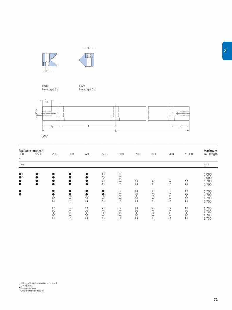
G
G
L
J1 J1J
G2
G3
l2) l l l l L L 1 000l2) l l l l L L 1 000l l l l l L L L L L L 1 700l l l l l L L L L L L 1 700
l l l l l L L L L L 1 700l l l l l L L L L L 1 700
L L L L L L L L L 1 700L L L L L L L L L 1 700
L L L L L L L L L 1 700L L L L L L L L L 1 700L L L L L L L L L 1 700L L L L L L L L L 1 700
Available lengths1) Maximum rail length100 150 200 300 400 500 600 700 800 900 1 000
L
mm mm
1) Other rail lengths available on request2) J = 35 mml) Prompt deliveryL) Delivery time on request
LWMHole type 13
LWVHole type 13
LWV
2
71

Needle roller assemblies
Designation Dimensions Load ratings for a cage with 2 rows of 10 needles
Maximum cage length
Appropriate rail guide
dynamic static Dw Lw U t t1 C10 C0 10
– mm N mm
LWHV 10 2 4,8 10 3,75 2,7 10 400 25 500 50 000 LWM/LWV 3015 LWHW 10 2 4,8 10 3,75 2,7 10 400 25 500 2 000 LWM/LWV 3015 LWHV 15 2 7,8 15 3,75 2,7 16 300 45 000 50 000 LWM/LWV 4020 + 5025 LWHW 15 2 6,8 15 4,5 3,5 14 600 42 500 2 000 LWM/LWV 4020 + 5025
LWHV 20 2,5 11,8 20 5 3,7 32 000 88 000 50 000 LWM/LWV 6035 LWHW 20 2,5 9,8 20 5,5 4 26 000 76 550 2 000 LWM/LWV 6035 LWHW 25 3 13,8 25 6 4,5 43 100 129 400 2 000 LWM/LWV 7040 LWHW 30 3,5 17,8 30 7 5 64 500 195 000 2 000 LWM/LWV 8050
UDw
Lw
t
t1
U
Dw
Lw
t
t1plastic aluminium
LWHV LWHW
LWM / LWV end pieces
Designation Dimensions Attachment screw Appropriate rail guideEnd pieces End pieces
with wiperDIN 7984
L L1
– mm – –
LWEM 3015 4 M 3 LWM 3015 LWEV 3015 4 M 3 LWV 3015
LWEAM 3015 6 M 3 LWM 3015 LWEAV 3015 6 M 3 LWV 3015
LWEM 4020 6,5 M 5 LWM 4020 LWEV 4020 6,5 M 5 LWV 4020
LWEAM 4020 8,5 M 5 LWM 4020 LWEAV 4020 8,5 M 5 LWV 4020
LWEM/LWEV 5025 to 8050 7 M 6 LWM / LWV 5025 to 8050LWEAM/LWEAV 5025 to 8050 9 M 6 LWM / LWV 5025 to 8050
L1Lwiper
LWEM LWEAM
L L1
wiper
LWEV LWEAV
72

2.7 LWM / LWV ACSZ
Rail guidesLWM / LWV ACSZ rail guides are identical to
LWM / LWV rail guides, but designed for use
with anti-creeping LWHW ACSZ cages. For
this purpose, both rails are equipped with
gear racks made of steel. The cage carries
two steel control gears that are always in
mesh with the racks during operation, and
help to ensure the right cage position. As
standard, the rails are prepared for maxi-
mum stroke, with gear racks over the full
rail length († chapter 1.4).
Needle roller assembliesIn principle, LWHW ACSZ are the same as
LWHW cages, whereby LWHW ACSZ needle
roller cages incorporate two steel control
gears located at the centre of the cage. The
load carrying capacity of LWHW ACSZ cages
is also identical with that of LWHW standard
cages. ACSZ does not result in additional
cage length. LWHW ACSZ needle roller
assemblies comprise an aluminium cage
with retained needle rollers.
End piecesGenerally, end pieces are not needed for
LWM / LWV ACSZ rail guides, since cage-
creeping is prevented by the ACSZ. For pro-
duction reasons, the tapped holes on the
rail’s end face are standard, and most end
pieces, as for LWM / LWV rail guides, can be
used with the exception of LWEAV. If tapped
holes on the end face are not required, the
rails should be ordered with option “E1”.
Ordering example
2x LWM 6035300 ACSZ
2x LWV 6035300 ACSZ
2x LWHW 20x220 ACSZ
73
2

LWM / LWV ACSZ precision rail guides
A
Dw
J3
J4
J5
J6
N2
N
A1
BN1
J2 N2
N
A2
B
N1
J2
A3
L
J1 J1J
G2
G3
LWM 3015 ACSZ 30 15 16 2 1,4 40 15 5,5 M 4 8,5 4,5 5,25 8 7 M 3 6LWV 3015 ACSZ 30 15 17,2 10,5 2 1,6 40 15 5,5 M 4 8,5 4,5 5,25 7 5,5 M 3 6LWM 4020 ACSZ 40 20 22,3 2 2,8 80 20 7,5 M 6 11,5 6,8 7,5 10 11 M 5 7LWV 4020 ACSZ 40 20 22 13,5 2 2,8 80 20 7,5 M 6 11,5 6,8 7,5 10,5 5,5 M 5 7
LWM 5025 ACSZ 50 25 28 2 4,5 80 20 10 M 6 11,5 6,8 7,5 12 13 M 6 8LWV 5025 ACSZ 50 25 28 17 2 4,4 80 20 10 M 6 11,5 6,8 7,5 13 7 M 6 8LWM 6035 ACSZ 60 35 36 2,5 7,3 100 25 11 M 8 15 9 10 14 20 M 6 8LWV 6035 ACSZ 60 35 36 20 2,5 7,6 100 25 11 M 8 15 9 10 18 8 M 6 8
LWM 7040 ACSZ 70 40 40 3 9,4 100 25 13 M 10 18,5 11 12,5 16 20 M 6 8LWV 7040 ACSZ 70 40 42 24 3 10,2 100 25 13 M 10 18,5 11 12,5 20 10 M 6 8LWM 8050 ACSZ 80 50 45 3,5 13,5 100 25 14 M 12 20 13 14 20 30 M 6 8LWV 8050 ACSZ 80 50 48,5 26 3,5 14,4 100 25 14 M 12 20 13 14 25 10 M 6 8
Designation Dimensions Weight Mounting holes End face holes
A B A1 A2 A3 Dw J1) J1 min2) J2 G N N1 N2 J3 J4 J5 J6 G2 G3
– mm kg/m mm – mm mm – mm
1) For lengths L < J+2 ¥ J1min : J = 50 mm (except for LWM/LWV 3015) 2) J1 = (L – ∑J) / 2
LWM ACSZ Hole type 15
LWV ACSZ Hole type 15
LWM ACSZ
74

G
G
L
J1 J1J
G2
G3
L2) L L L L L L 1 000L2) L L L L L L 1 000L L L L L L L L L L L 1 700L L L L L L L L L L L 1 700
L L L L L L L L L L 1 700L L L L L L L L L L 1 700
L L L L L L L L L 1 700L L L L L L L L L 1 700
L L L L L L L L L 1 700L L L L L L L L L 1 700L L L L L L L L L 1 700L L L L L L L L L 1 700
Available lengths1) Maximum rail length100 150 200 300 400 500 600 700 800 900 1 000
L
mm mm
1) Other rail lengths available on request2) J = 35 mml) Prompt deliveryL) Delivery time on request
LWM ACSZ Hole type 13
LWV ACSZ Hole type 13
LWV ACSZ
2
75

Needle roller assemblies
Designation Dimensions Load ratings for a cage with 2 rows of 10 needles
Maximum cage length
Appropriate rail guide
dynamic static Dw Lw U t t1 C10 C0 10
– mm N mm
LWHW 10 ACSZ 2 4,8 10 3,75 2,7 10 400 25 500 2 000 LWM/LWV 3015 ACSZLWHW 15 ACSZ 2 6,8 15 4,5 3,5 14 600 42 500 2 000 LWM/LWV 4020 + 5025 ACSZLWHW 20 ACSZ 2,5 9,8 20 5,5 4 26 000 76 550 2 000 LWM/LWV 6035 ACSZLWHW 25 ACSZ 3 13,8 25 6 4,5 43 100 129 400 2 000 LWM/LWV 7040 ACSZLWHW 30 ACSZ 3,5 17,8 30 7 5 64 500 195 000 2 000 LWM/LWV 8050 ACSZ
U
Dw
Lw
t
t1LWHW ACSZ
LWM / LWV ACSZ end pieces
Designation Dimensions Attachment screw Appropriate rail guideEnd pieces End pieces
with wiperDIN 7984
L L1
– mm – –
LWEM 3015 4 M 3 LWM 3015 ACSZLWEV 3015 4 M 3 LWV 3015 ACSZ
LWEAM 3015 6 M 3 LWM 3015 ACSZ
LWEM 4020 6,5 M 5 LWM 4020 ACSZLWEV 4020 6,5 M 5 LWV 4020 ACSZ
LWEAM 4020 8,5 M 5 LWM 4020 ACSZ
LWEM/LWEV 5025 to 8050 7 M 6 LWM / LWV 5025 to 8050 ACSZLWEAM 5025 to 8050 9 M 6 LWM / LWV 5025 to 8050 ACSZ
L1Lwiper
LWEM LWEAM
L L1
wiper
LWEV LWEAV
76

LWRPM / LWRPV Slide coating
Designation1) Dimensions LoadRail guide capacity2)
H C
– mm N / 100 mm
LWRPM 3 0,7 300 LWRPM 6 1,7 700 LWRPM 9 1,7 1 200
2.8 LWRPM / LWRPV
Rail guidesLWRPM/LWRPV rail guides are linear guides
for limited travel, fitted with Turcite-B slide
coating. Based on PTFE, this material is
self-lubricating and offers excellent sliding
properties. The coating is bonded to the
non-hardened LWRPM rail and subse-
quently ground to size. Separate ordering of
the slide coating is not required. The LWRPV
rail is hardened and ground. In order to
avoid damage to the sliding surface of the
LWRPM rail, the LWRPV rail has a lead-in
radius as standard. LWRPM/LWRPV rail
guides should be used where rail guides
with rolling element assemblies are unsuit-
able due to external influences, for example,
extremely short strokes, high impact loads
or dusty environment. The mounting and
interface dimensions of the LWRPM/LWRPV
rail guides conform to those of all the SKF
Modular Range rail guides included in this
catalogue. More details can be found in
chapter “Technical data of precision rail
guides with slide coating”.
LWRPM/LWRPV rail guides are character-
ised by:
•Stick-slip-freeoperation.•Smoothrunning.•Goodemergencyrunningproperties.•Lowwearandhighreliability.•Resistancetocontamination.•Excellentvibrationdampingproperties.
End piecesLWRPM/LWRPV rail guides normally do not
require end pieces. For this reason, tapped
holes on the end faces are also unnecessary.
However, for production reasons, LWRPV
rail guides will, in certain cases, be supplied
with tapped holes.
Ordering example:
2 ¥ LWRPM 6300
2 ¥ LWRPV 6300
H
1) The slide coating is an integral part of the LWRPM rail and does not have to be ordered separately.
2) For a surface loading of approx. 1 N/mm2 (momentary loads of up to 6 N/mm2 are permissible).
77
2

A
H
LWRPM / LWRPV precision rail guides
G
J2
A1
B
N1
N
G1 G
J2
N
A2
G1
A3
B
N1
L
J1 J1J
LWRPM 3 18 8 9,5 0,49 25 12,5 5 3,5 M 4 3,3 6 3,2LWRPV 3 18 8 9,6 6,45 0,48 25 12,5 5 3,5 M 4 3,3 6 3,2LWRPM 6 31 15 16,6 1,6 50 25 7 6 M 6 5,2 9,5 5,2LWRPV 6 31 15 17,8 10,8 1,61 50 25 7 6 M 6 5,2 9,5 5,2
LWRPM 9 44 22 23,1 3,35 100 50 7 9 M 8 6,8 10,5 6,2LWRPV 9 44 22 26,9 16,6 3,71 100 50 7 9 M 8 6,8 10,5 6,2
Designation1) Dimensions Weight Mounting holes
A B A1 A2 A3 J J1 J1 min J2 G G1 N N1
– mm kg/m mm – mm
1) Sizes LWRPM/LWRPV 12 and LWRPM/LWRPV 15 are available on request.
LWRPM LWRPV
LWRPM
78

L
J1 J1J
1) Other rail lengths are available on request but new J1 dimension has to be calculated as described in chapter 3.1.7, Calculation of J1 dimension.l) Prompt deliveryL) Delivery time on request
LWRPV
l l l l l l l L L L L 400l l l l l l l L L L L 400
L l l l l l L L L L L L L L 1 200l l l l l L l L L L L L L 1 200
l l l l L L L L L 1 500l l l L L L L L L 1 500
Available lengths1) Maximum rail length50 75 100 125 150 175 200 225 250 275 300 350 400 450 500 550 600 650 700 800 900 1 000
L
mm mm
2
79

Besides the standard product range, on
request SKF can offer additional cages and
guiding types, such as flat rail guides or
wrap-around guidings. Also, completely
customized guidings can be manufactured
for applications that do not allow the use of
standard products.
2.9.1 LWML / LWVThe LWML rail guide consists of a modified
LWM rail guide with the addition of an inte-
grated adjustment wedge († chapter 3.1.10,
fig. 6). Used in conjunction with an LWV guide
and a needle roller assembly, this provides a
preload-adjustable guide system. Inclination
of the wedge surface is 1,5%, so that a dis-
placement of the wedge by 1 mm brings
about a 15 µm alteration in the height.
LWML rail guides are available in classes
P10 and P5. When ordering, it should be
specified whether the preloading threads
are right-hand or left-hand threads.
2.9.2 LWN / LWOLWN/LWO rail guides differ from the
LWM/LWV rail guides only in height, width
and attachment holes. The internal geom-
etry of the two rail guide series is the
same and their load ratings are identical.
LWN/LWO rail guides are available in preci-
sion classes P10, P5 and P2.
2.9.3 LWJ / LWS flat rail guides
LWJ/LWS flat rail guides are used in con-
junction with LWRM/LWRV, LWM/LWV or
LWN/LWO rail guides as non-locating linear
guides. They are incorporated in floating
slides. LWJ/LWS flat rail guides, as well as
the appropriate rolling element assemblies
and end pieces, are available on request.
Customised guidings
With the knowledge and manufacturing
capabilities existing within SKF, it is possible
for SKF to produce completely customized
guidings or other precision parts.
2.9 Other products
80

GCL and GCLA are pre-assembled slides
made of steel or aluminium, and crossed
roller precision rail guides for applications
that require maximum accuracy and rigidity.
Typical applications are factory automation,
printing, packaging and general machinery.
GCL and GCLA standard slides are available
on request.
Advantages:
• Top and base plate of a GCL are made of
blackened steel or cast iron (depending on
size) or aluminium for GCLA.
• Standard patterns of attachment holes for
easy mounting.
• Upper and lower mounting surfaces are
ground for high running accuracy.
• Reference edge parallel to the slide axis
(opposite of preload set screws).
• Internal end stops to limit the stroke.
• Very low friction of the rail guides.
• Relubrication identical with precision rail
guides, († chapter 3.3).GCL / GCLA data
Guidings:GCL / GCLA 2 LWRB 2 with LWJK 2GCL / GCLA 3 LWR 3 with LWAK 3GCL / GCLA 6 LWR 6 with LWAL 6GCL / GCLA 9 LWR 9 with LWAL 9
Optional with anti creeping solution ACS/ACSM and / or coating
Operating temperature –30 to +80 °CMaximum speed 2 m/sMaximum acceleration 25 m/s2
Friction coefficient 0,003–0,005 (with normal, light lubrication)Preload Preloaded in factory with standard valuesPrecision class P10 (other precision class on request)Lubrication Lightly greased on assembly
Optional customized solutions possible
LGCL / GCLA running accuracy
GCL
Stroke (mm) 25 50 100 200 300
Straightness height Tz 2 mm 2 mm 3 mm 3 mm 4 mmStraightness side Ty 2 mm 2 mm 2 mm 3 mm 3 mm
GCLA
Stroke (mm) 25 50 100 200 300
Straightness height Tz 4 mm 4 mm 6 mm 7 mm 8 mmStraightness side Ty 4 mm 4 mm 5 mm 6 mm 7 mm
2.10 GCL / GCLA standard slides
81
2

GCL
H
J6J2
T
N
N1
L
n ¥ J
B1
J1 J1
G
Dw
H3H1
H2
S/2 S/2
B
GCL 2030 40 21 35 18 18 2 M3 7 14 8 17,5 15GCL 2045 50 30 1¥15GCL 2060 65 40 46 2¥15GCL 2075 80 50 60 3¥15GCL 2090 95 60 75 4¥15GCL 2105 110 70 90 5¥15GCL 2120 125 80 105 6¥15
GCL 3050 60 28 55 30 28 3 M4 9 18,5 10 27,5 25 GCL 3075 80 45 55 1¥25 GCL 3100 105 60 80 2¥25 GCL 3125 130 75 105 3¥25 GCL 3150 155 90 130 4¥25 GCL 3175 180 105 155 5¥25 GCL 3200 205 130 180 6¥25
GCL 6100 100 45 110 60 70 45 6 M6 13 31 15,5 55 50 GCL 6150 160 95 120 1¥50 GCL 6200 210 130 170 2¥50 GCL 6250 260 165 220 3¥50 GCL 6300 310 200 270 4¥50 GCL 6400 410 280 370 6¥50
GCL 9200 145 60 210 130 72 9 M8 16 43 20,5 105 80GCL 9300 310 180 1¥100GCL 9400 410 350 2¥100GCL 9500 510 450 3¥100
Designation1) Dimensions–0,2 ±0,1 Stroke2)
–0,4
B H L S1 S2 B1 Dw G H1 H2 H3 n ¥ J J1 J2
– mm – mm
1) Delivery time generally on request2) S1 standard stroke order designation, e.g. GCL 2060,
S2 extended stroke order designation, e.g. GCL 2060/L3) Take chapter 1.7.2, in consideration.
82
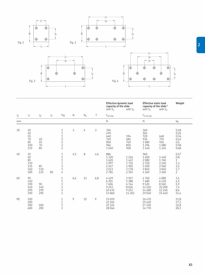
B J6
J7
L
B J6
J8
J7
L
B J6
J8
J7
L
J6
L
B
J9
J8
J7
Fig. 1
Fig. 3
Fig. 2
Fig. 4
30 25 1 3 6 3 394 360 0,1840 1 499 504 0,2655 1 640 594 720 648 0,3470 40 2 769 684 936 792 0,4285 55 2 850 769 1 080 936 0,5100 70 2 966 850 1 296 1 080 0,58115 85 2 1 040 928 1 440 1 224 0,68
40 35 1 4,5 8 4,6 886 960 0,57 60 1 1 320 1 216 1 600 1 440 0,8 85 1 1 620 1 422 2 080 1 760 1 110 1 1 997 1 716 2 720 2 240 1,3 135 85 3 2 267 1 905 3 200 2 560 1,5 160 110 3 2 613 2 178 3 840 3 040 1,7 185 135 85 4 2 781 2 355 4 160 3 360 2
60 90 1 6,6 11 6,8 4 429 3 927 4 760 4 080 3,1 140 1 6 301 5 388 7 480 6 120 4,5 190 90 3 7 606 6 744 9 520 8 160 5,9 240 140 3 9 253 8 026 12 240 10 200 7,2 290 190 3 10 435 9 253 14 280 12 240 8,6 390 290 3 13 060 11 202 19 040 15 640 11,4
90 100 1 9 15 9 15 659 16 470 11,8200 1 22 102 25 620 17,3300 100 3 23 324 27 450 22,8400 200 3 28 046 34 770 28,3
Effective dynamic load capacity of the slide
Effective static load capacity of the slide3)
Weight
with S1 with S2 with S1 with S2
J6 J7 J8 J9 Fig N N1 T Ceff slide C0 eff slide
mm N N kg
2
83

GCLA
GCLA 2030 40 21 35 18 18 2 M3 7 14 8 17,5 15GCLA 2045 50 30 1¥15GCLA 2060 65 40 46 2¥15GCLA 2075 80 50 60 3¥15GCLA 2090 95 60 75 4¥15GCLA 2105 110 70 90 5¥15GCLA 2120 125 80 105 6¥15
GCLA 3050 60 25 55 30 28 3 M4 9 18,5 10 27,5 25 GCLA 3075 80 45 55 1¥25 GCLA 3100 105 60 80 2¥25 GCLA 3125 130 75 105 3¥25 GCLA 3150 155 90 130 4¥25 GCLA 3175 180 105 155 5¥25 GCLA 3200 205 130 180 6¥25
GCLA 6100 100 40 110 60 70 45 6 M6 13 31 15,5 55 50 GCLA 6150 160 95 120 1¥50 GCLA 6200 210 130 170 2¥50 GCLA 6250 260 165 220 3¥50 GCLA 6300 310 200 270 4¥50 GCLA 6400 410 280 370 6¥50
GCLA 9200 145 50 210 130 72 9 M8 16 43 20,5 105 80GCLA 9300 310 180 1¥100GCLA 9400 410 350 2¥100GCLA 9500 510 450 3¥100
Designation1) Dimensions–0,2 ±0,1 Stroke2)
–0,4
B H L S1 S2 B1 Dw G H1 H2 H3 n ¥ J J1 J2
– mm – mm
1) Delivery time generally on request2) S1 standard stroke order designation, e.g. GCLA 2060,
S2 extended stroke order designation, e.g. GCLA 2060/L3) Take chapter 1.7.2, in consideration.
H
J6J2
T
N
N1
L
n ¥ J
B1
J1 J1
G
Dw
H3H1
H2
S/2 S/2
B
84

30 25 1 3 6 3 394 360 0,1140 1 499 504 0,1555 1 640 594 720 648 0,1970 40 2 769 684 936 792 0,2385 55 2 850 769 1 080 936 0,27100 70 2 966 850 1 296 1 080 0,31115 85 2 1 040 928 1 440 1 224 0,35
40 35 1 4,5 8 4,6 886 960 0,29 60 1 1 320 1 216 1 600 1 440 0,42 85 1 1 620 1 422 2 080 1 760 0,55 110 1 1 997 1 716 2 720 2 240 0,68 135 85 3 2 267 1 905 3 200 2 560 0,81 160 110 3 2 613 2 178 3 840 3 040 0,94 185 135 85 4 2 781 2 355 4 160 3 360 1,1
60 90 1 6,6 11 6,8 4 429 3 927 4 760 4 080 1,5 140 1 6 301 5 388 7 480 6 120 2,3 190 90 3 7 606 6 744 9 520 8 160 3 240 140 3 9 253 8 026 12 240 10 200 3,8 290 190 3 10 435 9 253 14 280 12 240 4,5 390 290 3 13 060 11 202 19 040 15 640 6
90 100 1 9 15 9 15 659 16 470 5,9200 1 22 102 25 620 8,7300 100 3 23 324 27 450 11,4400 200 3 28 046 34 770 14,2
Effective dynamic load capacity of the slide
Effective static load capacity of the slide3)
Weight
with S1 with S2 with S1 with S2
J6 J7 J8 J9 Fig N N1 T Ceff slide C0 eff slide
mm N N kg
B J6
J7
L
B J6
J8
J7
L
B J6
J8
J7
L
J6
L
B
J9
J8
J7
Fig. 1
Fig. 3
Fig. 2
Fig. 4
2
85

With the LZM miniature slide product
range, SKF offers the ideal solution for linear
motion applications with short strokes and
compact boundary dimensions. The use of
miniature slides has significantly increased
in medical applications, measurement tech-
nologies and micro mechanics and
assembly.
The various LZM miniature slide com-
ponents are designed to meet the highest
precision standards. LZM miniature slides
feature high running accuracy and smooth
motion, and are manufactured with all-
stainless-steel components. The maximum
value for parallelism between the raceways
and the mounting surface is 3 µm. Optimized
hardness enables long service life and high
performance within compact boundary
dimensions.
Ease of installation is another positive
feature of LZM miniature slides. Unlike
crossed roller systems using 4 rails and
2 cages to be assembled on the production
floor, the LZM miniature slide provides a
complete slide that can simply be bolted into
place without the use of precision devices to
set preload.
Customized miniature slides are also
possible, and SKF will modify existing
designs to meet specific technical require-
ments. Wide versions of LZMs for higher
torque loads can also be supplied on
request. Wide versions of LZMs for higher
torque loads, comparable with wide minia-
ture profile rail guides LLMWS, can also be
supplied on request.
Applications:
• Pneumatics
• Semi-conductor manufacturing
• Medical
• Micro- and electronics assembly
• Measurement applications
• Fibre optics
Advantages:
• Compact design
• High load capacity
• Very good running accuracy
• Smooth running
• High rigidity
• Easy assembly
Ordering example
• LZMHS 9 – 26
(P5, T0 as standard – no need to specify)
• LZMHS 9 – 26 T2 P1
2.11 LZM miniature slide
86

LZM data
LZM technical data
Design Four point contact with identical load angles
Standard range Four sizes: 7, 9, 12 and 15
Optional range Wide versions for 9, 12 and 15
Operating temperature –20 up to +80 °C
Max. speed 3 m/s
Max. acceleration 80 m/s2 (for preloaded LZMs)
Preload classes T0 = light clearance; StandardT1 = zero play to light preloadT2 = preloaded
Precision classes P5 = standardP1 = high
Lubrication Slides are pre-lubricated with ”Paraliq P460”
Material specifications
Carriage and rail Steel 1.4034 / 1.4037Balls Steel 1.3541End pieces PlasticCage Plastic
Dimensional tolerance of H
Precision class mm
P5 +–0,02P1 +–0,01
87
2

LZM miniature slides
h
H1
d3
d2
W3
H
Mx
W2
M1
W
Hct
M2
E F E
n × L5
My
LZM HS 7 – 26 26 5 8 29 – 17 12 7 8 2,35 M2 ¥ 2,5 6LZM HS 7 – 34 34 5 8 37 0 17 12 7 8 2,35 M2 ¥ 2,5 8LZM HS 7 – 50 50 5 8 53 30 17 12 7 8 2,35 M2 ¥ 2,5 12LZM HS 7 – 66 66 5 8 69 30 17 12 7 8 2,35 M2 ¥ 2,5 16
LZM HS 9 – 32 32 9,5 13 35 – 20 15 9 10 3,55 M3 ¥ 3 4LZM HS 9 – 42 42 8 13 45 0 20 15 9 10 3,55 M3 ¥ 3 6LZM HS 9 – 55 55 8 13 58 20 20 15 9 10 3,55 M3 ¥ 3 8LZM HS 9 – 81 81 8 13 84 2¥20 20 15 9 10 3,55 M3 ¥ 3 12LZM HS 9 – 94 94 8 13 97 3¥20 20 15 9 10 3,55 M3 ¥ 3 14
LZM HS 12 – 37 37 11 15 40 – 27 20 12 13 4,7 M3 ¥ 3,5 4LZM HS 12 – 51 51 10,5 15 54 0 27 20 12 13 4,7 M3 ¥ 3,5 6LZM HS 12 – 66 66 10,5 15 69 25 27 20 12 13 4,7 M3 ¥ 3,5 8LZM HS 12 – 96 96 10,5 15 99 50 27 20 12 13 4,7 M3 ¥ 3,5 12LZM HS 12 – 126 126 10,5 15 129 3¥25 27 20 12 13 4,7 M3 ¥ 3,5 16
LZM HS 15 – 52 52 16 20 56 – 32 25 15 16 6 M3 ¥ 4 4LZM HS 15 – 85 85 12,5 20 89 0 32 25 15 16 6 M3 ¥ 4 8LZM HS 15 – 105 105 12,5 20 109 40 32 25 15 16 6 M3 ¥ 4 10LZM HS 15 – 165 165 12,5 20 169 80 32 25 15 16 6 M3 ¥ 4 16
Designation Dimensions
Number of threads M1L L1 L2 L4 n ¥ L5
1) W W2 W3 H H1 M1 ¥ depth
– mm
1) – means no hole; L5 = 0 means one hole in the center
88

L1 L2
L
L1L2
L4
Mz
5,5 15 2,5 ¥ 4,5 ¥ 2,5 M3 2 24 700 1 100 3,5 6 4,62 9,5 15 2,5 ¥ 4,5 ¥ 2,5 M3 2 34 900 1 400 5,5 7 4,62 10 15 2,5 ¥ 4,5 ¥ 2,5 M3 3 50 1 100 2 000 12 10 4,62 10,5 15 2,5 ¥ 4,5 ¥ 2,5 M3 4 66 1 400 2 700 21 14 4,62
6 20 3,5 ¥ 6,5 ¥ 3,5 M4 2 28 1 200 1 800 7 12 5,12 11 20 3,5 ¥ 6,5 ¥ 3,5 M4 2 40 1 400 2 100 11 15 5,12 7,5 20 3,5 ¥ 6,5 ¥ 3,5 M4 3 54 1 900 3 400 18 19 5,12 10,5 20 3,5 ¥ 6,5 ¥ 3,5 M4 4 78 2 500 4 900 43 29 5,12 7 20 3,5 ¥ 6,5 ¥ 3,5 M4 5 92 2 700 5 500 57 33 5,12
6 25 3,5 ¥ 6,5 ¥ 4,5 M4 2 32 2 200 3 300 11 21 6,5 13 25 3,5 ¥ 6,5 ¥ 4,5 M4 2 47 2 600 4 300 22 28 6,5 8 25 3,5 ¥ 6,5 ¥ 4,5 M4 3 62 3 000 5 300 36 36 6,5 10,5 25 3,5 ¥ 6,5 ¥ 4,5 M4 4 95 3 800 7 200 76 52 6,5 13 25 3,5 ¥ 6,5 ¥ 4,5 M4 5 122 4 700 9 700 131 68 6,5
6 40 3,5 ¥ 6,5 ¥ 4,5 M4 2 50 2 800 3 900 25 42 7,65 22,5 40 3,5 ¥ 6,5 ¥ 4,5 M4 2 80 4 600 7 800 73 70 7,65 12,5 40 3,5 ¥ 6,5 ¥ 4,5 M4 3 102 5 100 9 100 106 84 7,65 22,5 40 3,5 ¥ 6,5 ¥ 4,5 M4 4 162 7 300 15 000 264 131 7,65
Number of threads M2E F d3 ¥ d2 ¥ h M2 Max. stroke C C0 MyCo / MzCo MxCo Hct
mm – mm mm
2
89
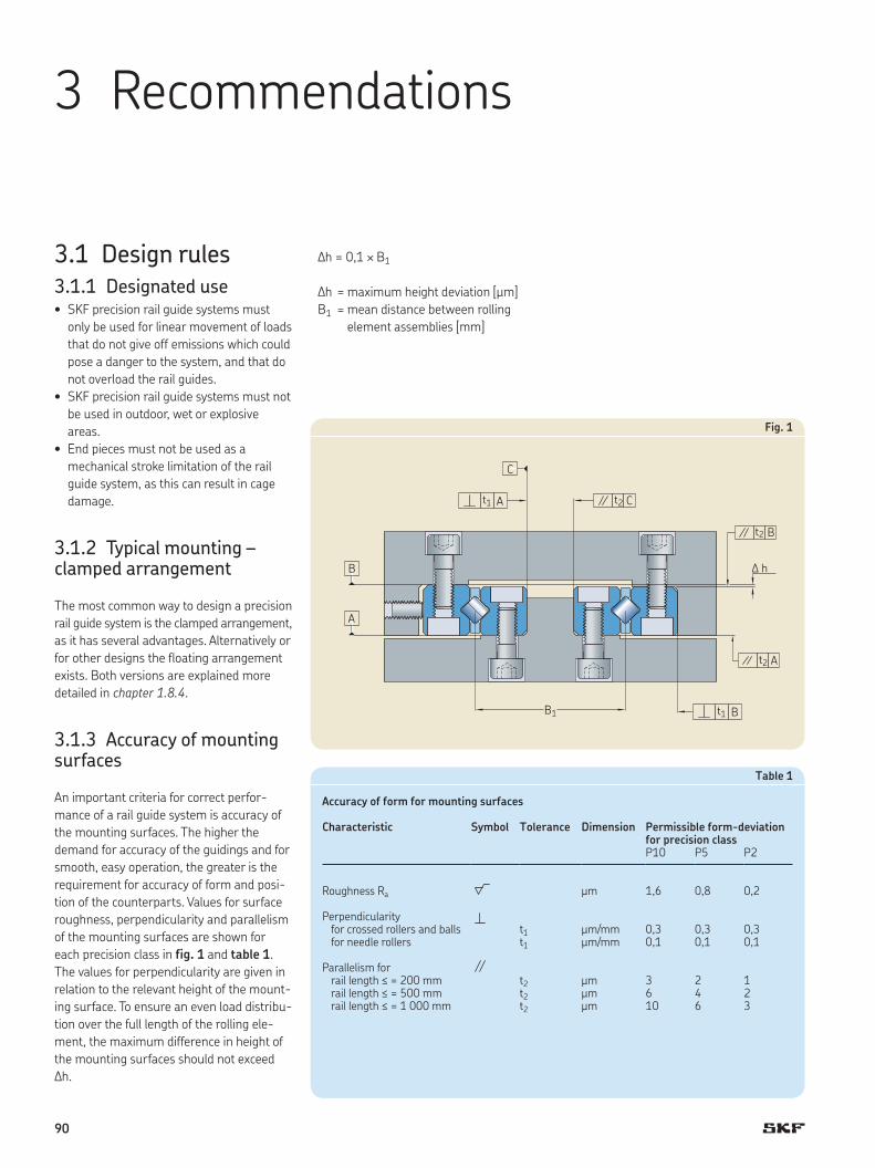
3 Recommendations
3.1 Design rules3.1.1 Designated use• SKF precision rail guide systems must
only be used for linear movement of loads
that do not give off emissions which could
pose a danger to the system, and that do
not overload the rail guides.
• SKF precision rail guide systems must not
be used in outdoor, wet or explosive
areas.
• End pieces must not be used as a
mechanical stroke limitation of the rail
guide system, as this can result in cage
damage.
3.1.2 Typical mounting – clamped arrangement
The most common way to design a precision
rail guide system is the clamped arrangement,
as it has several advantages. Alternatively or
for other designs the floating arrangement
exists. Both versions are explained more
detailed in chapter 1.8.4.
3.1.3 Accuracy of mounting surfaces
An important criteria for correct perfor-
mance of a rail guide system is accuracy of
the mounting surfaces. The higher the
demand for accuracy of the guidings and for
smooth, easy operation, the greater is the
requirement for accuracy of form and posi-
tion of the counterparts. Values for surface
roughness, perpendicularity and parallelism
of the mounting surfaces are shown for
each precision class in fig. 1 and table 1.
The values for perpendicularity are given in
relation to the relevant height of the mount-
ing surface. To ensure an even load distribu-
tion over the full length of the rolling ele-
ment, the maximum difference in height of
the mounting surfaces should not exceed
∆h.
Fig. 1
∆h = 0,1 ¥ B1
∆h = maximum height deviation [µm]
B1 = mean distance between rolling
element assemblies [mm]
C
B
A
t2 C
t2
D h
B
t2 A
t1 A
t1B1 B
Table 1
Accuracy of form for mounting surfaces
Characteristic Symbol Tolerance Dimension Permissible form-deviation for precision class
P10 P5 P2
Roughness Ra µm 1,6 0,8 0,2
Perpendicularity for crossed rollers and balls for needle rollers
µm/mmµm/mm
t1 0,3 0,3 0,3t1 0,1 0,1 0,1
Parallelism for rail length ≤ = 200 mm rail length ≤ = 500 mm rail length ≤ = 1 000 mm
t2 µm 3 2 1t2 µm 6 4 2t2 µm 10 6 3
90

Description of kinematic
Not overrunning rail guide without wipers (Standard)
Rail guide with wipers Overrunning rail guide without wipers
Type of rail
Type of ACS
Long rail Short rail Long rail Short rail
LWRLWRBLWRE
no with end pieces without end pieces
with end pieces and wipers
with end pieces without end pieces
LWRE ACS end pieces not needed, but front face of rails equipped with mounting threads. So end pieces mountable by customer.
without end pieces
with end pieces and wipers
end pieces not needed, but front face of rails equipped with mounting threads. So end pieces mountable by customer.
without end pieces
LWRE ACSM without end pieces without end pieces
with end pieces and wipers
without end pieces without end pieces
LWM / VLWRM / V
no with end pieces on one rail only (on M- or V-shaped rail)
without end pieces
with end pieces and wipers
with end pieces without end pieces
LWM / V ACSZ end pieces not needed, but front face of rails equipped with mounting threads. So end pieces mountable by customer.
without end pieces
with end piece and wipers mounted at the rail with – M-shaped cross
section: o.k. – V-shaped cross section: not
feasible
end pieces not needed, but front face of rails equipped with mounting threads. So end pieces mountable by customer.
without end pieces
Can not be changed
Can be changed on request
LrailLcage
Lrail
Lcage
Lrail, long
Lcage
Lrail, short
Lrail, long
Table 2
End pieces logic
3.1.4 End pieces logicTogether with the different kinematics, also
the end pieces have to be selected accord-
ingly. Table 2 shows the logic.
3
91

3.1.5 Chamfers on the precision rail guides
For the design of surrounding parts, the tol-
erance of the chamfer between the two ref-
erence surfaces of the precision rail guide
must be taken into account. The value c is
depending on the rail width B († fig. 2).
Rail width B ≤ 8 mm: c = 0,4 mm
Rail width B > 8 mm: c = 0,7 mm
3.1.6 Tolerance of distance between mounting holes
The tolerance of distance between the
mounting holes depends on the rail length
Lrail, which has an impact on possible
thermal expansion during heat treatment.
The values shown below are valid for all
mounting holes along the rail. Rails with
tighter tolerances for the distance between
the holes can be supplied on request. For
long rails, the use of special mounting
screws (LWGD) is recommended († fig. 3).
Lrail ≤ 300: t = 0,6 mm
Lrail > 300: t = 0,0016 mm ¥ Lrail
Fig. 2
Fig. 3
Fig. 4
A
B
c × 45°
B
Lrail
J1 J
Jn ×A n ×
t A
L
J1 (J1)J
A
B
3.1.7 Calculation of J1 dimension
Usually the J1 dimension is chosen symmet-
rically on both rail ends. If so, the symmetric
J1 dimension can be calculated with the fol-
lowing formula. The minimum of J1, J1 min, is
stated in the product tables and has to be
taken in consideration.
If an unsymmetric J1 dimension is needed
it can be stated in the ordering code by
using the definition of J1 as shown in figure
“J1 unsymmetrical” († fig. 4).
L–S JJ1 = K—— 2
92

3.1.8 Special mounting screws LWGD
Special mounting screws LWGD help to
compensate for manufacturing tolerances.
The screw strength class is 8.8. All dimen-
sions are given in († table 3).
Table 3
LWGD special mounting screws
Designation1) Dimensions Appropriate rail guide Size
– G1 G2 L4 L5 D d SW – –
LWGD 3 M3 5 12 3 5 2,3 2,5 r 3LWGD 4 M3 5 16 3 5 2,3 2,5 s LWR 4LWGD 2211 M4 5 14 4 6 3 3 s LWRE 2211LWGD 6 M5 8 20 5 8 3,9 4
f LWRM, LWRV 6LWGD 9 M6 12 30 6 8,5 4,6 5
s LWRPM, LWRPV 9
LWGD 12 M8 17 40 8 11,3 6,25 6 c 12
LWGD 4020 M6 14 16 5 8 3,9 4 r 4020LWGD 5025 M6 14 21 5 8 3,9 4 s 5025LWGD 6035 M8 15 30 6 8,5 4,6 5 f LWM, LWV 6035LWGD 7040 M10 17 33 8 11,3 6,3 6 s 7040LWGD 8050 M12 19 41 12 15,8 9,6 10 c 8050
1) other sizes are available on request.
d G1
G2
L5 L4
D
SW width across flats
3
93

3.1.9 PreloadingPrecision rail guides with rolling elements
and in clamped arrangement should always
be mounted without clearance and thus
with a certain preload. Preloading enhances
the rigidity of the system as well as the run-
ning accuracy. Peaks of load at the end of
the cages, caused by torque load My and Mz
are consequently decreased.
The magnitude of the adjustable preload
depends on the actual application and can
be up to 20% of the dynamic load carrying
capacity of the rail guide. The presence of
preload means that the load acting on the
rolling elements must be reduced, and this
should be taken into consideration when the
operating conditions require high preload.
Associated components need corresponding
stiffness.
Rail guides can be preloaded in many
ways. Some examples are shown in
(† fig. 5 to 7). The most common method
is the use of set screws for adjustment. The
number of these screws should at least be
equal to the mounting holes in the rail.
Experience is needed to use this method
successfully, in order to avoid “pinching” the
rail assembly. Table 4 gives approximate
values for a good running precision rail
guide system with a balance of rigidity and
friction.
Preloading of rolling assemblies with any
ACS system is done using the same values.
The use of adjustment bars or adjust-
ment wedges is recommended in cases
where large preloads are required or where
high demands are placed on running accu-
racy. For needle roller cages, SKF can offer
the LWML rail, which is equipped with a
built-in adjustment wedge.
3.1.10 Tightening torques for mounting screws
Depending on the material of the adjacent
components and the screw size, different
values of tightening torques have to be
used for mounting a precision rail guide
(† table 5). Given values are also valid for
the special mounting screws LWGD.
Fig. 7
Preloading with lateral wedge
Fig. 6
Preloading with LWML rail
Fig. 5
Preloading with set screws
94

Table 4
Tightening torques of set screws
Rail type Cage type Set screw distance
Set screw
Factor for preload
Tightening torque
– – mm – % Ncm
LWRB 1 LWJK 1,588 10 M2 20 1,8LWRB 2 LWJK 2 15 M3 10 1,7
LWR 3 LWAK3 25 M3 13 3LWR 3 LWAK3 25 M4 13 4LWR 6 LWAL6 50 M5 9 17LWR 6 LWAL6 50 M6 9 20,4LWR 9 LWAL9 100 M6 8 67,9LWR 9 LWAL9 100 M8 8 90LWR 12 LWAL12 100 M10 8 153,6
LWRE 3 LWAKE3 25 M3 7 6,2LWRE 3 LWAKE3 25 M4 7 8,3LWRE 2211 LWAKE3 40 M3 7 9,9LWRE 2211 LWAKE3 40 M4 7 13,2LWRE 4 LWAKE4 25 M3 5 9,5LWRE 4 LWAKE4 25 M4 5 12,7LWRE 6 LWAKE6 50 M5 3 26,9LWRE 6 LWAKE6 50 M6 3 32,4LWRE 9 LWAKE9 100 M6 3 102,2LWRE 9 LWAKE9 100 M8 3 135,4
LWRM / LWRV 6 LWHV10 50 M6 5 96,9LWRM / LWRV 6 LWHW10 50 M6 5 96,9LWRM / LWRV 9 LWHV15 100 M8 2 161LWRM / LWRV 9 LWHW15 100 M8 2 120,2
LWM / LWV 3015 LWHV10 40 M6 5 77,5LWM / LWV 3015 LWHW10 40 M6 5 77,5LWM / LWV 4020 LWHV15 80 M8 2 128,8LWM / LWV 4020 LWHW15 80 M8 2 96,1LWM / LWV 5025 LWHV15 80 M8 2 128,8LWM / LWV 5025 LWHW15 80 M8 2 96,1LWM / LWV 6035 LWHV20 100 M10 2 294,9LWM / LWV 6035 LWHW20 100 M10 2 217,8LWM / LWV 7040 LWHW25 100 M12 2 395,9LWM / LWV 8050 LWHW30 100 M12 2 507,9
Table 5
Tightening torque of mounting screws
Data for mounting screws in strength class 8.8
Material Screw size M2 M2,5 M3 M3,5 M4 M5 M6 M8 M10 M12 M14
Aluminum Tightening torque [Nm] 0,21 0,44 0,77 1,2 1,7 3,4 6 15 29 50 80Minimum screw-in length [mm] 3,2 4 4,8 5,6 6,4 8 10 13 16 19 22
Cast iron Tightening torque [Nm] 0,25 0,52 0,92 1,4 2,1 4,1 7 17 34 60 94Minimum screw-in length [mm] 3 3,8 4,5 5,3 6 7,5 9 12 15 18 21
Steel Tightening torque [Nm] 0,3 0,61 1,1 1,6 2,4 4,8 8 20 40 69 110Minimum screw-in length [mm] 2,4 3 3,6 4,2 4,8 6 7,2 10 12 14 17
Note: Precision rail guides with slide coating should not be preloaded.
3
95

3.2 Mounting3.2.1 Important requirements
The following instructions describe the
mounting procedures for a SKF precision rail
guide system. Read these instructions care-
fully before starting the installation process.
Skill and cleanliness are essential when
mounting precision rail guides, to obtain
optimum performance and to avoid mount-
ing-induced bearing failure. Mounting
should be carried out in a dry, dust-free
room away from metal-working machines
and other machinery producing swarf or
dust. Prior to mounting the rail guides, all
necessary parts and equipment should be
at hand. Appropriate tools and measuring
devices are to be used at all times. Rail
guides are precision products and should be
handled with due care. Not following these
instructions could reduce system service life
or create a safety risk.
3.2.2 General mounting rulesAll parts of the linear guiding system should
be carefully cleaned and deburred and the
accuracy of form and dimension of all adja-
cent components checked against the speci-
fication, († chapter, 3.1.3). The rails should
not be removed from their original packag-
ing until immediately before mounting, to
minimise the risk of contamination. After
unwrapping, the corrosion inhibitor has to
be removed. When using SKF LGEP2
grease, the corrosion inhibitor can remain
on the raceways. The reference surfaces of
the rails and the mounting surfaces of the
adjacent parts should be carefully cleaned
and lightly oiled to prevent contact corrosion
during operation. The reference surface A is
generally on the opposite side of the SKF
label. Apply the chosen lubricant onto the
raceways and the rolling element assem-
blies prior to mounting.
NOTE: To retain the high performance of
precision rail guides, it is recommended not
to mix rails of different packages (compare
chapter 1.6.12).
3.2.3 Mounting of rail guides without Anti-Creeping System
Mounting of a rail guide in a clamped
arrangement should take place in the
following sequence (fig. 8):
1 Inner rails 3 and 4 are pressed against
the mounting surfaces and bolted down,
applying the prescribed torque.
2 Fixed rail 1 is pressed against the mating
mounting surfaces and bolted down,
applying the prescribed torque.
3 The outer rail 2 is pressed onto its
counterpart and bolted lightly in position.
4 The lubricated cages 5 and 6 are moved
to their desired position (usually centred).
5 The outer rail 2 is used for preload
adjustment because a system in clamped
arrangement has to be operated with zero
clearance or with preload, depending on
the application. The preload is adjusted by
means of set screws 7 with the help of a
torque wrench. For the correct adjust-
ment sequence, follow the numbers on
the set screws as described in Fig. 9. Be
sure to tighten the set screws from inside
to outside, and have rolling elements
underneath the corresponding set screws.
Recommended tightening torques, which
should only be considered as approximate
values, are given in table 4, chapter 3.1.9.
6 The fixing bolts on the outer rail 2 are
tightened by applying the prescribed
torque.
7 The running accuracy of the slide assembly
is checked.
8 The end pieces, if applicable, are mounted.
9 The external end stops of the slide
assembly are mounted. The rolling ele-
ment assemblies should not be used as
counterparts for the end stops.
12
34
56
7
Fig. 8
Mounting sequence
UNIT 1 UNIT 2
96

Fig. 9
Preload sequence
3.2.4 Mounting of rail guides with Anti-Creeping System
In order to avoid damage to the Anti-Creep-
ing System, the rails have to be mounted as
pre-assembled units with the cages correct-
ly positioned. Any direct or indirect force
subjected to the ACS control gear will
damage it.
The following instructions are valid for all
types of Anti-Creeping Systems (ACS, ACSM,
ACSZ).
1 Outer rail 1, inner rail 3, and lubricated
cage 5 are put together as unit 1 with
the cage in its correct position – typically
centred.
2 Unit 2 should be prepared in the same
way by using inner rail 4, outer rail 2
and cage 6.
3 Both units are pushed in to the desired
position between the bottom and top
part from the front side.
4 Unit 1 is pressed against the mounting
surfaces and bolted down, applying the
prescribed torque.
5 Inner rail 4 is pressed against the mat-
ing mounting surfaces and bolted down,
applying the prescribed torque.
6 Outer rail 2 is mounted onto its counter-
part, and bolted lightly in position.
7 The outer rail 2 is used for preload
adjustment because a system in clamped
arrangement has to be operated with
zero clearance or with preload, depend-
ing on the application. The preload is
adjusted by means of set screws 7 with
the help of a torque wrench. For the
correct adjustment sequence, follow the
numbers on the set screws as described
in fig. 9. Be sure to tighten the set
screws from inside to outside and have
rolling elements underneath the corre-
sponding set screws. Recommended
tightening torques, which should only be
considered as approximate values, are
given in table 4, chapter 3.1.9.
8 The fixing bolts on the outer rail 2 are
tightened by applying the prescribed
torque.
9 The running accuracy of the slide
assembly is checked.
10 The end pieces, if applicable, are
mounted.
11 The external end stops of the slide
assembly are mounted. The rolling ele-
ment assemblies should not be used as
counterparts for the end stops.
3 1 2
6 4
5 7
Moving part in centre position; screws 1, 2, 3
Moving part in end position; screws 4, 6
Moving part in other end position, screws 5, 7
3
97

3.3 Maintenance3.3.1 LubricationSKF precision rail guides usually require
very small quantities of lubricant. Both
grease and oil can be used. Lubricants with
solid additives, or grinding emulsions and
coolants are unsuitable.
Under normal operating conditions,
grease is generally used to lubricate rail
guides. Compared to oil, grease is more
easily retained in the bearing arrangement,
particularly where the rail guides are
mounted in an inclined or vertical position.
Grease also contributes to the sealing of the
rail guide against contamination and
humidity.
Since rail guides, particularly in low speed
applications, operate almost exclusively
under borderline or mixed friction condi-
tions, the use of grease with extreme pres-
sure (EP) additives is advisable. SKF recom-
mends using SKF bearing grease LGEP2.
This grease is based on lithium soap and
mineral oil. It has excellent water repellent
and corrosion resistance properties and can
be used in the temperature range –20 °C to
+110°C.
Oil lubrication is often employed in
situations where neighbouring machine
components are oil lubricated, or where
high speeds of travel are involved. A simple
method of lubrication with oil is the oil drop
method. Ordinary mineral oil with EP addi-
tives and viscosities in the range of ISO VG
45 to 200 is suitable.
Lubricant can be supplied to the rail
guides most easily using the lateral gap
between the rails. If this is not possible
because of the design of the arrangement,
rails provided with lubrication holes can be
supplied, in which case a drawing should be
forwarded to SKF, indicating the size and
location of the holes. It is also possible to
connect central lubrication units, which can
be offered by SKF. Be aware that the ACS
control gears and its axis must also be
lubricated.
3.3.2 Relubrication intervalThere are no general rules given for re-
lubrication intervals for precision rail guides,
as these must be individually determined for
each application. However, we recommend
re-lubricating at least once a year.
3.3.3 RepairsIf a precision rail guide system has reached
the end of its service life and needs to be
replaced, SKF recommends replacing the
complete system. When re-ordering, please
identify the size, rail length, J1 dimension
(distance from rail end to first mounting
hole), hole type and cage length / stroke.
3.3.4 Stationary conditions / shipping / storage
If a precision rail guide is stationary for long
periods and subjected to vibration from
external sources, micro movement in the
contact zone between rolling elements and
raceways will lead to damage of those sur-
faces. This damage can result in a significant
increase in running noise, and premature
failure due to material fatigue. Damage of
this kind should be avoided at all costs, for
instance by isolating the bearings from
external vibration and by taking suitable
precautions during transport.
98

Ordering code precision rails
LWRE90300 ACS 50/P5/J1=25
TypeRBRRERMRVMVRPMRPV
SizeFor example 6, 9 or 6035, depending on type
Length in mmFor sizes 1, 2, 3, 4, 6, 2211 and 3015: 3 digits For sizes 9 and 4020 to 8050: 4 digits
Anti-creeping systemNo code without any ACSACS for LWREACSM for LWRB and LWREACSZ for LWM/LWV
Stroke of anti-creeping system in mm († chapter 1.4)No code standard, teeth over the entire length Value possible for ACS and ACSZ, not for ACSM; always symmetrical;
Precision classP10 standard (no code needed)P5 mediumP2 high
Lead in radiusNo code withoutEG lead in radius on both ends
Material / CoatingNo code standard, as described in product tablesHV rails in stainless steel (standard for ACSM)HD thin dense chrome coating
End face holesNo code standard, as described in product tablesE1 without end holes (standard for ACSM, LWRPM and LWRPV)E7 with end holes (for ACSM, LWRPM and LWRPV)
Mounting hole options (on request)No code standard, as described in product tables03 threaded hole10 through hole13 threaded inserts integrated in the rail (only LWM and LWV)15 through hole with counterbore (standard at LWM and LWV, no code needed)
J1 dimension in mmNo code standard, symmetrical J1 on both endsValue unsymmetrical J1 in mm; definition († chapter 3.1.7)
3.4 Ordering code
LW RE 9 0300 ACS 50 / P5 / / / / / J1= 25
3
99

Ordering code rolling element assemblies
LWAKE9x13 ACS
TypeJK for LWRBAL, AK for LWRAKE for LWREHV, HW for LWRM/V and LWM/V
Size1, 2 for LWJK3 for LWAK6, 9, 12 for LWAL3, 4, 6, 9 for LWAKE10, 15 for LWHV10, 15, 20, 25, 30 for LWHW
LengthNumber of rolling elements for ball- and roller cagesLength in mm for needle roller cages
Anti-creeping systemNo code without any ACSACS for LWAKEACSM for LWJK and LWAKEACSZ for LWHW
Precision classNo code standard, as described in product tablesG1 high (only available for needle roller cages)
LW AKE 9 x 13 ACS /
Ordering code special mounting screws
LWGD 9
Size1)
3, 4, 6, 9, 12, 2211 for all rails of the Modular Range and size 22114020, 5025, 6035, 7040, 8050 for LWM/V
Generally the same size as for the rail has to be entered.
LWGD
1) Other sizes on request
100

Ordering code end pieces
LWERE 9
Type1)
ERA for LWR / LWRBERB for LWR / LWRBERC with wiper for LWR
ERE for LWREEREC with wiper for LWRE
ERM for LWRMERV for LWRVEARM with wiper for LWRMEARV with wiper for LWRV
EM for LWMEV for LWVEAM with wiper for LWMEAV with wiper for LWV
Size1 ... 8050Generally the same size as for the rail has to be entered.
CoatingNo code standard, as described in product tablesHV chromed end pieces and screws
Ordering code precision rail guides in kit packaging
TypeRRE
Size3, 6 for R3, 4, 6 for RE
Rail length in mm (as defined in product tables)
Length of short rail in mm (optional, on request)No code standard, four rails with the same rail lengthValue two short rails with given length and lead in radius
and two normal rails
Anti-creeping systemNo code without any ACSACS for LWRE 3, 4, 6ACSM for LWRE 3, 6
Number of rolling elements z (optional, on request)No code standard, as described in product tablesValue when other number of rolling elements is needed
LW /
LW RE 3 300 / 100 EG ACS – KIT / z 10
1) Take table 2, Chapter 3.1.4, in consideration
3
101

102

Please complete the form with all available information and send it to your SKF representative or authorized distributor for product selection.
SKF contact Date
General information
Customer ContactCompany Contact name
Address 1 Job title
Address 2 Department
Post code / Zip City State Phone (including country code) Mobile (including country code)
Country Mail
Reason for requestCurrent product / brand Description
○ Replacement ○ New design ○ Other
Application / Industry
○ Factory automation ○ Food and beverage ○ Machine tools Description
○ Medical ○ Semiconductor ○ Other
Application description
Specification sheet – Precision rail guide
3
103

Stroke Rail length Length of shorter rail Distance B1 Distance B1 + A Guiding system
o r
Maximum height
mm mm mm mm mm mm
(† chapter 1.8.5) ○ No constraints
Required service life distance or time (ill in all ields) Required static safety (in accordance to your business and application)Distance Total time Period of one cycle Stroke of one cycle
km h s mm
Maximum speed1) Maximum acceleration1) Rigidity of guiding system Running accuracy of guiding system
Parallelism in height
m/s m/s2 N/µm µm
1) Here the maximum values. Enter load phase speciic values in table “External loads and load phases”
Parallelism in sideward direction
○ No speciic requirements µm
EnvironmentPresence of dust, dirt or luids Requirements on friction
○ Clean environment, e.g. laboratory ○ Lowest possible friction
○ Standard industrial environment ○ Standard friction
○ Dirty environment, e.g. milling machine ○ No requirement
○ Humid or corrosive environment Preferred material
If yes, please describe: ○ No preference (standard)
○ Stainless steel
○ Coated steel
Temperature [°C]Minimum Operating Maximum ○ Shock loads or vibrations
If yes, please describe:
Lubricant in use
○ Standard (SKF grease LGEP2) ○ OtherPlease specify:
Sketch of the application (or attach a drawing)
Speciication sheet – Precision rail guide
104

Product details
Rail designation (if already known)
Precision class of rail
○ P10 (Standard) ○ P5 (Medium) ○ P2 (High)
Designation of rolling element assembly (if already known)
Anti-creeping system needed (recommended for high accellerations or vertical systems)
○ Yes ○ No
Needed accessories (for details see SKF publication 14259, Precision rail guides)
○ End pieces Designation
○ End pieces with wipers (requires long and short rails)
Designation
○ Special mounting screws – LWGD
Precision rail guides mounted into a complete system
○ GCL ○ GCLA ○ System with drive, e.g. roller screw
Specification sheet – Precision rail guide
3
105

Input for dimensioning calculation
Moving direction (set coordinate system accordingly)Please specify:
○ Horizontal ○ Vertical ○ Other
External loads and load phases
Forces in N, Lever arms in mm measured from deined origin (see graphcis above). If the application has more than 3 load phases, please copy this page.
Load phase 1 Load phase 2 Load phase 3
Stroke mm Stroke mm Stroke mm
Acceleration mm/s2 Acceleration mm/s2 Acceleration mm/s2
Speed m/s Speed m/s Speed m/s
Lever arms in Lever arms in Lever arms in
Force Fx x y z Force Fx x y z Force Fx x y z
Force Fy x y z Force Fy x y z Force Fy x y z
Force Fz x y z Force Fz x y z Force Fz x y z
Speciication sheet – Precision rail guide
ORIGIN
+z
ORIGINORIGINORIGINORIGINORIGINORIGINORIGINORIGINORIGINORIGINORIGINORIGINORIGIN ORIGIN
Fz, i
Fx, iFy, i
zi
yixi
+z
+Fy
+x
+Fx
Fx, drive
+Fz
+y
B1+A
+x
zdrive
B1
106

3

® SKF is a registered trademark of the SKF Group.
Turcite-B is a registered trademark of Busak & Shamban GmbH
© SKF Group 2016The contents of this publication are the copyright of the publisher and may not be reproduced (even extracts) unless prior written permission is granted. Every care has been taken to ensure the accuracy of the information contained in this publication but no liability can be accepted for any loss or damage whether direct, indirect or consequential arising out of the use of the information contained herein.
PUB MT/P1 14259 EN · February 2016
This publication supersedes publication 4183, leaflet LF 6602 and leaflet LF 33.
Certain image(s) used under license from Shutterstock.com
skf.com