Embed Size (px)
Citation preview

Pro Elite ™ Professional SeriesWater Treatment System by GE
For Sales & Service questions please
contact your dealer:
Your local dealer is:
Pro Elite Platinum/Silver Control
Operation Manual

2
Rev C
3
Rev C
QUICK START
TABLE OF CONTENTS
INSTALLER QUICK-START SHEET 4
MANUAL OVERVIEW 9
How To Use This ManualSafety InformationValve FeaturesLocation SelectionWater Line ConnectionDrain Line ConnectionOverflow Line ConnectionRegenerant Line ConnectionElectrical ConnectionValve Camshaft
SYSTEM DISINFECTION 22
Disinfection Of Water Conditioners
DETERMINING IF YOU HAVE A SILVER OR PLATINUM SERIES CONTROL 24
GENERAL PRO ELITE INSTRUCTIONS 24
Display Icons Pro Elite ControlKeypad — ButtonsRegeneration ModesSilver/Platinum Series Initial Power-UpInitial Start-up Step-By-Step Instructions
PLACING CONDITIONER INTO OPERATION (turning on the water) 35
PROGRAMMING THE PRO ELITE FOR 5-CYCLE FILTER APPLICATIONS 38
Manganese Greensand Systems
SILVER/PLATINUM SERIES ADVANCED PROGRAMMING 41
SILVER/PLATINUM SERIES LEVEL II PROFESSIONAL PROGRAMMING 42
PARTS AND ACCESSORIES 45
TROUBLESHOOTING 48

4
Rev C
QUICK START
INSTALLER QUICK-START SHEET
See Determining If You Have a Silver or Platinum Series Control on page 24
to identify your controller.
Silver Control - Electronic time clock control capable of doing 7-day (day of week)
regeneration, or up to a 99 interval day regeneration. This control will operate
both in a conditioner (softener) or 3-cycle filter mode with the same controller.
Platinum Control - Electronic metered-demand (volumetric) controller which
regenerates based on the water usage of the installation site. A calendar override
is a standard feature on this controller.
For 5-cycle filter applications, see page 38 for setting details.
Initial Power-up
Initial Power Up - (CAMSHAFT proceeds to HOME position)
• At initial power-up, the camshaft will need to rotate to the HOME
(in service) position.
• Camshaft may take 1-2 minutes to return to home position.
• Err 3 will be displayed until the camshaft returns to home.
• If more than 2 minutes elapses, verify that the motor is turning the camshaft .
If it is not turning, see the troubleshooting section.
Time & Day
Regen Time & Day
Salt
SU MO TU WE TH FR SA DAYS
LBS
PMMIN
KG
x100x2
PHC
Capacity
Hardness
Manual RegenerationUP ButtonSET ButtonDOWN Button
LCD Display
Time & Day
Regen Time & Day
Salt
Capacity
Hardness
SU MO TU WE TH FR SA DAYS
NOTE: The controller features a self-test sequence. At first power-up of
the control, you may see a number such as 1.00, 1.02, 1.04, or 2.00
displayed. This is an indication that the self-test is not completed. To
complete the test , verify that the turbine cable is connected. Blow into
the turbine port (valve outlet) to spin the turbine. The controller will verify
that the turbine works and the self test will finish. Proceed with the initial
start up procedure.

5
Rev C
QUICK START
Initial Start-up Step-by-step Instructions
Step 1: Select Valve Type
This step may have been performed by your system’s OEM manufacturer.
In this case, proceed to step 3.
• Identify your valve body type by looking at the silver ID sticker on the
back or side of the valve body.
• Select your valve body type using the UP or DOWN buttons.
• The display will show several valve types. The Pro Elite uses the 263
filter valve and the 268 conditioner valve. The other valves will be
displayed only.
Display Valve Body
255 Not used
263 Filter 263, 3-cycle filter
268 Conditioner 268, 7-cycle conditioner
273 Not used
278 Not used
293 Not used
298 Not used
Step 2: Program System Size
This step may have been performed by your system’s OEM manufacturer. In this
case, proceed to step 3.
• Input system size - resin volume - in cubic feet or liters.
• Use UP and DOWN buttons to scroll through resin volume choices.
• Choose the nearest volume to your actual system size.
• To choose a 3-cycle filter operation - press DOWN until an "F" is displayed.
• Press SET to accept the system size you’ve selected.
• If incorrect setting is programmed, see "Resetting the Control" section below.
Step 3: Program Time of Day
• While "12:00" is blinking, set the correct time of day.
• Use the UP and DOWN buttons to scroll to the correct time of day.
• "PM" is indicated, "AM" is not indicated.
• Press SET to accept the correct time of day and advance to the next
parameter.
Step 4: Set Day of Week
• Press SET to make the arrow under SU flash.
• Use the UP and DOWN buttons to advance the arrow until it is under the
correct day of week.
• Press SET to accept and advance to the next parameter.
Step 5: Set Regen Time
• 2:00 (AM) is the default time of regeneration. To accept this time, press the
DOWN button to move to step 6.
• To change the regen time, press SET - causing 2:00 to flash.
• Use the UP and DOWN buttons to advance to the desired regen time.
• Press SET to accept the time and advance to the next parameter.
Step 6: Set Days to Regenerate (Silver Series Time-clock Control Only)
• If using Platinum Series control - proceed to step 6a.
Time & Day
Regen Time & Day
Salt
SU MO TU WE TH FR SA DAYS
Capacity
Hardness
Time & Day
Regen Time & Day
Salt
SU MO TU WE TH FR SA DAYS
Capacity
Hardness
Time & Day
SU MO TU WE TH FR SA DAYS
Capacity
Hardness
Time & Day
Regen Time & Day
Salt
SU MO TU WE TH FR SA DAYS
Capacity
Hardness
Time & Day
Regen Time & Day
Salt
SU MO TU WE TH FR SA DAYS
Capacity
Hardness
Time & Day
Regen Time & Day
Salt
SU MO TU WE TH FR SA DAYS
Capacity
Hardness

6
Rev C
QUICK START
• Set number of days between time-clock regeneration (regen frequency).
• Default time is 3 days.
• Days can be adjusted from 1/2 (.5) to 99 days.
• To change, press SET to make the "3" flash.
• Use the UP and DOWN buttons to change to the number of days desired.
• Press SET to accept the regen frequency, and advance to the next cycle.
To use the 7-day timer option - see full Dealer Installation Manual.
Step 6a: Set Calendar Override (Platinum Series Demand Control Only)
• If using Silver Series control - proceed to step 7.
• Set number of days for calendar override on demand control.
• "0" days is the default for calendar override.
• Days can be adjusted from 1/2 (.5) to 99 days.
• To change, press SET to make the "0" flash.
• Use the UP or DOWN buttons to change to the number of days desired.
• Press SET to accept the regen frequency, and advance to the next cycle.
Step 7: Set Salt Amount (Regenerant Amount)
• Default setting is "9 pounds per ft3 (110 g/L).
• Use UP or DOWN to select regenerant amount.
• Press SET to accept the setting and advance to next parameter.
See page 31 for more complete information on regenerant settings for different system sizes, capacities and expected efficiencies.
Step 8: Estimated Capacity
• System capacity is displayed in total kilograins or kilograms of hardness removed before a regeneration is necessary.
• Value is derived from the system’s resin volume input, and salt amount input .
• The capacity displayed is a suggested value - as recommended by resin manufacturers.
• Capacity is only displayed for information purposes on Silver Series control - it does not (and cannot) need to be changed.
• To change capacity on Platinum Series control, press SET to make the default capacity flash. Use the UP and DOWN buttons to increment to the desired capacity.
• Press SET to accept the setting and advance to the next parameter.
If using Silver Series control, programming is complete. The control will return you to the normal operation
mode.
Time & Day
Regen Time & Day
Salt
SU MO TU WE TH FR SA DAYS
Capacity
Hardness
Time & Day
Regen Time & Day
Backwash Time
SU MO TU WE TH FR SA DAYS
Capacity
Hardness
KG
Time & Day
Regen Time & Day
Salt
SU MO TU WE TH FR SA DAYS
Capacity
Hardness
7Rev C
QUICK START
Step 9: Enter Hardness (Platinum Series Demand Control Only)
• Enter inlet water hardness at installation site.
• Default hardness setting is 25 grains (25 ppm for metric)
• To change hardness, press SET to make the setting flash. Use the UP and DOWN buttons to scroll to the correct hardness.
• Press SET to accept the entered hardness value.
• The control will return you to the normal operation mode.
Initial system programming is now complete. The control will return to normal
operation mode, if a button is not pushed for 30 seconds.
For system start-up procedure, including: purging the mineral tank, refilling the regenerant tank, and drawing
regenerant, see Initial Startup Step-By-Step Instructions on page 29.
Manual Regeneration Procedures
To Initiate a Manual Regeneration:
• Press REGEN once for delayed regeneration.
System will regenerate at next set regen time (2:00 AM).A flashing regen (recycle) symbol will be displayed.
• Press and hold REGEN for 5 seconds to initiate immediate manual regeneration. A solid regen symbol will be displayed.
• After immediate regeneration has begun, press REGEN again to initiate a second manual regeneration. An X2 symbol will be displayed, indicating a second regeneration will follow the first regeneration.
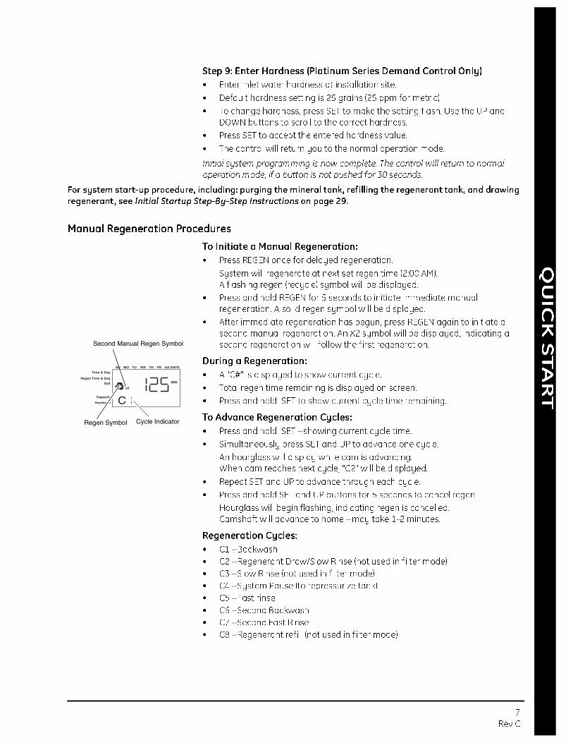
During a Regeneration:
• A "C#" is displayed to show current cycle.
• Total regen time remaining is displayed on screen.
• Press and hold SET to show current cycle time remaining.
To Advance Regeneration Cycles:
• Press and hold SET - showing current cycle time.
• Simultaneously press SET and UP to advance one cycle.
An hourglass will display while cam is advancing.When cam reaches next cycle, "C2" will be displayed.
• Repeat SET and UP to advance through each cycle.
• Press and hold SET and UP buttons for 5 seconds to cancel regen.
Hourglass will begin flashing, indicating regen is cancelled.Camshaft will advance to home - may take 1-2 minutes.
Regeneration Cycles:
• C1 - Backwash
• C2 - Regenerant Draw/Slow Rinse (not used in filter mode)
• C3 - Slow Rinse (not used in filter mode)
• C4 - System Pause (to repressurize tank)
• C5 - Fast rinse
• C6 - Second Backwash
• C7 - Second Fast Rinse
• C8 - Regenerant refill (not used in filter mode)
Time & Day
Regen Time & Day
Salt
SU MO TU WE TH FR SA DAYS
CCapacity
Hardness
MIN
x2
Cycle IndicatorRegen Symbol
Second Manual Regen Symbol

8 Rev C
Resetting The Control
To reset the control:
1. Press and hold SET and DOWN simultaneously for 5 seconds.
2. H0 and the system’s set resin volume (or "F" mode) will be displayed.
3. If a history value other than "H0" is displayed, use the up arrow to scroll through the settings until "H0" is displayed.
4. To reset the control, press and hold SET for 5 seconds.
5. The control will be reset to an unprogrammed state.
6. Go to "Initial Set-up" section of this sheet to reprogram control.
Further programming or set-up instructions can be found in this manual.
Unprogrammed control after reset
Resetting the Pro Elite Control
Time & Day
Regen Time & Day
Salt
SU MO TU WE TH FR SA DAYS
HCapacity
Hardness
Time & Day
Regen Time & Day
Salt
SU MO TU WE TH FR SA DAYS
Capacity
Hardness
WARNING: Resetting the control will delete all information stored in its
memory. This will require you to reprogram the control completely from
the initial power up mode.
How To Use This Manual 9Rev C
MANUAL OVERVIEW
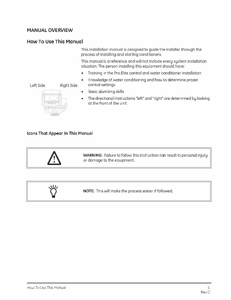
How To Use This Manual
This installation manual is designed to guide the installer through the process of installing and starting conditioners.
This manual is a reference and will not include every system installation situation. The person installing this equipment should have:
• Training in the Pro Elite control and water conditioner installation
• Knowledge of water conditioning and how to determine proper control settings
• Basic plumbing skills
• The directional instructions "left" and “right" are determined by looking at the front of the unit .
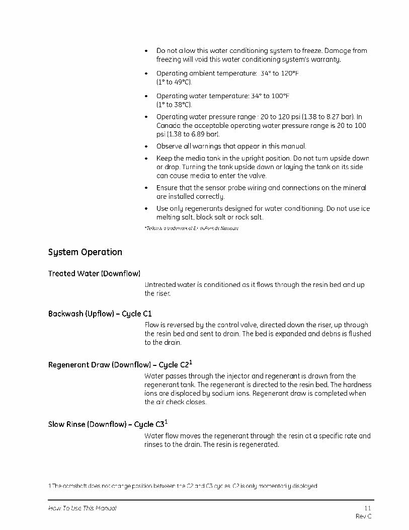
Icons That Appear In This Manual
Left Side Right Side
WARNING: Failure to follow this instruction can result in personal injury or damage to the equipment.
NOTE: This will make the process easier if followed.

10 How To Use This Manual
Rev C
Safety Information
The Pro Elite water conditioner’s control valve conforms to NSF/ANSI 44 and 61 for materials and structural integrity only. Generic systems were tested and certified by WQA as verified by the performance data sheet.
• Please review the entire Installation and Operation Manual before installing the water conditioning system.
• As with all plumbing projects, it is recommended that a trained professional water treatment dealer install the water conditioning system. Please follow all local plumbing codes for installing this water conditioning system.
• This system will not make microbiologically unsafe water safe. Water that is unsafe must be treated separately from this conditioner.
• This water conditioning system is to be used only for potable water.
• Inspect the water conditioning system for carrier shortage or shipping damage before beginning installation.
• Use only lead-free solder and flux, as required by federal and state codes, when installing soldered copper plumbing.
• Use caution when installing soldered metal piping near the water conditioning system. Heat can adversely affect the plastic control valve and bypass valve.
• All plastic connections should be hand tightened. Teflon* tape may be used on connections that do not use an O-ring seal. Do not use pipe dope type sealants on the valve body. Do not use pliers or pipe
wrenches.
• Do not use petroleum-based lubricants such as Vaseline, oils or hydrocarbon-based lubricants. Use only 100% silicone lubricants.
• Use only the power transformer supplied with this water conditioning system.
• All electrical connections must be completed according to local codes.
• The power outlet must be grounded
• Install an appropriate grounding strap across the inlet and outlet piping of the water conditioning system to ensure that a proper ground is maintained.
CAUTION: Dry location use only, unless used with a Listed Class 2 Power Supply suitable for outdoor use.
• To disconnect power, unplug the AC adapter from its power source.
• Observe drain line requirements. The drain line must be a minimum of 1/2-inch diameter. Use 3/4-inch pipe if the backwash flow rate is greater than 7 gpm (26.5 Lpm) or the pipe length is greater than 20 feet (6 m).
• Do not support the weight of the system on the control valve f ittings, plumbing, or the bypass.
TEST
EDAND CERTIF
IED
UNDER
INDUSTRY ST
AN
DARDS
How To Use This Manual 11
Rev C
• Do not allow this water conditioning system to freeze. Damage from freezing will void this water conditioning system’s warranty.
• Operating ambient temperature: 34° to 120°F (1° to 49°C).
• Operating water temperature: 34° to 100°F (1° to 38°C).
• Operating water pressure range : 20 to 120 psi (1.38 to 8.27 bar). In Canada the acceptable operating water pressure range is 20 to 100 psi (1.38 to 6.89 bar).
• Observe all warnings that appear in this manual.
• Keep the media tank in the upright position. Do not turn upside down or drop. Turning the tank upside down or laying the tank on its side can cause media to enter the valve.
• Ensure that the sensor probe wiring and connections on the mineral are installed correctly.
• Use only regenerants designed for water conditioning. Do not use ice melting salt , block salt or rock salt .
*Teflon is a trademark of E.I. duPont de Nemours.
System Operation
Treated Water (Downflow)
Untreated water is conditioned as it flows through the resin bed and up
the riser.
Backwash (Upflow) – Cycle C1
Flow is reversed by the control valve, directed down the riser, up through
the resin bed and sent to drain. The bed is expanded and debris is flushed
to the drain.
Regenerant Draw (Downflow) – Cycle C21
Water passes through the injector and regenerant is drawn from the
regenerant tank. The regenerant is directed to the resin bed. The hardness
ions are displaced by sodium ions. Regenerant draw is completed when
the air check closes.
Slow Rinse (Downflow) – Cycle C31
Water flow moves the regenerant through the resin at a specific rate and
rinses to the drain. The resin is regenerated.
1.The camshaft does not change position between the C2 and C3 cycles. C2 is only momentarily displayed.

12 How To Use This Manual
Rev C
Repressurization – Cycle C4
Pressure is balanced in the valve before continuing the regeneration.
Fast Rinse (Downflow) - Cycle C5
Water passes through the resin bed and up through the riser to drain. All
remaining regenerant residual is rinsed from the resin bed.
2nd Backwash (Upflow) – Cycle C6
Flow is identical to C1 Backwash. The resin is reclassif ied.
2nd Rinse (Downflow) - Cycle C7
Flow is identical to C5 Fast Rinse. The resin bed is rinsed to quality.
Regenerant Refill – Cycle C8
Water is directed to the regenerant tank to create regenerant for the next
regeneration.
Figure 1
Cycle Water Flows
Backwash Fast RinseService Regenerant Draw/Slow Rinse
From Regenerant Tank
Repressurize
To RegenerantTank
Refill

Valve Features 13
Rev C
Valve Features
Figure 2
Valve Identification
Refill Controller
Regenerant Tube Connection
Injector and cap
Valve Discs
Outlet
Drain
Inlet
Backwash
Injector Screen
Camshaft
Drain Control
Filter
Control ModuleMount
One Piece ValveDisc Spring
Motor
Optical Sensor
Right Side
Left Side

14 Location Selection
Rev C
Figure 3
Pro Elite Control Identification
Location Selection
Location of a water treatment system is important. The following
conditions are required:
• Level platform or floor
• Room to access equipment for maintenance and adding regenerant
(salt) to tank.
• Ambient temperatures over 34°F (1°C) and below 120°F (49°C).
• Water pressure below 120 psi (8.27 bar) and above 20 psi
(1.4 bar).
• In Canada the water pressure must be below 100 psi (6.89 bar).
• Constant electrical supply to operate the controller.
• Total minimum pipe run to water heater of ten feet (three meters) to
prevent backup of hot water into system.
• Local drain for discharge as close as possible.
• Water line connections with shutoff or bypass valves.
• Must meet any local and state codes for site of installation.
• Valve is designed for minor plumbing misalignments. Do not support
weight of system on the plumbing.
• Be sure all soldered pipes are fully cooled before attaching plastic
valve to the plumbing.
CAUTION: Dry location use only, unless used with a Listed Class 2 Power
Supply suitable for outdoor use.
Time & Day
Regen Time & Day
Salt
SU MO TU WE TH FR SA DAYS
LBS
PMMIN
KG
x100x2
PHC
Capacity
Hardness
LCD Display
Manual Regen ButtonDown Button
Set Button Up Button
Silver/Platinum Series Turbine Input or Dry Contact Signal Input
Main Motor &
Optical Sensor
Connection
AC Adapter
(low voltage)
Input
No Salt DetectorConnection
Front
Back

Water Line Connection 15
Rev C
Outdoor Locations
When the water conditioning system is installed outdoors, several items
must be considered.
• Moisture — The valve and controller are rated for NEMA 3 locations.
Falling water should not affect performance.
The system is not designed to withstand extreme humidity or water
spray from below. Examples are: constant heavy mist , near corrosive
environment, upwards spray from sprinkler.
• Direct Sunlight — The materials used will fade or discolor over time in
direct sunlight. The integrity of the materials will not degrade to cause
system failures.
• Temperature — Extreme hot or cold temperatures may cause damage
to the valve or controller.
Freezing temperatures will freeze the water in the valve. This will cause
physical damage to the internal parts as well as the plumbing.
High temperatures will affect the controller. The display may become
unreadable but the controller should continue to function. When the
temperature drops down into normal operating limits the display will
return to normal.
• Insects — The controller and valve have been designed to keep all but
the smallest insects out of the critical areas. Any holes in the top plate
can be covered with a metal foil duct work tape. The top cover should
be installed securely in place.
• Wind — The Pro Elite cover is designed to withstand a 30 mph
(48 Kph) wind when properly installed on the valve.
Water Line Connection
A bypass valve system should be installed on all water conditioning
systems. Bypass valves isolate the conditioner from the water system and
allow unconditioned water to be used. Service or routine maintenance
procedures may also require that the system is bypassed. Figures 4 and 5
show the two common bypass methods.

16 Water Line Connection
Rev C
Figure 4
Series 1265 bypass
Figure 5
Typical Globe Valve Bypass System
Normal Operation In Bypass
BYPASSBYPASS
BY
PA
SS
BY
PA
SS
Water
Conditioner
In Out
Water
Conditioner
In Out
WaterC
WaterC di i
Normal Operation In Bypass
Water
Conditioner
Water
Conditioner
WARNING: The inlet water must be connected to the inlet port of the
valve. When replacing non-Autotrol valves, the inlet and outlet may be
reversed. It is also possible for the plumbing to be installed in an
opposite order.
Do not solder pipes with lead-based solder.
WARNING: Do not use tools to tighten plastic fittings. Over time, stress
may break the connections. When the 1265 bypass valve is used, only
hand tighten the plastic nuts.

Drain Line Connection 17
Rev C
Drain Line Connection
1. The unit should be above and not more than 20 feet (6.1 m) from the
drain. Use an appropriate adapter fitting to connect 1/2-inch (1.3 cm) plastic tubing to the drain line connection of the control valve.
2. If the backwash flow rate exceeds 5 gpm (22.7 Lpm) or if the unit is located 20-40 feet (6.1-12.2 m) from drain, use 3/4-inch (1.9 cm) tubing. Use appropriate f ittings to connect the 3/4-inch tubing to the3/4-inch NPT drain connection on valve.
3. The drain line may be elevated up to 6 feet (1.8 m) providing the run does not exceed 15 feet (4.6 m) and water pressure at the conditioner is not less than 40 psi (2.76 bar). Elevation can increase by 2 feet (61 cm) for each additional 10 psi (.69 bar) of water pressure at the drain connector.
4. Where the drain line is elevated but empties into a drain below the level of the control valve, form a 7-inch (18-cm) loop at the far end of the line so that the bottom of the loop is level with the drain line connection. This will provide an adequate siphon trap.
Where the drain empties into an overhead sewer line, a sink-type trap must be used.
Secure the end of the drain line to prevent it from moving.
Figure 6Drain Line Connection
WARNING: Do not use petroleum grease on gaskets when connecting bypass plumbing. Use only 100% silicone grease products when installing any plastic valve. Non-silicone grease may cause plastic components to fail over time.
NOTE: Standard commercial practices are expressed here. Local codes may require changes to the following suggestions. Check with local authorities before installing a system.
Right WayAir Gap
Drain

18 Overflow Line Connection
Rev C
Overflow Line Connection
(not used with 3-cycle filter system)
In the event of a malfunction, the regenerant TANK OVERFLOW will direct “overflow” to the drain instead of spilling on the floor. This fitting should be on the side of the cabinet or regenerant tank. Most tank manufacturers include a post for the tank overflow connector.
To connect the overflow line, locate hole on side of tank. Insert overflow fitting into tank and tighten with plastic thumb nut and gasket as shown (Figure 7). Attach length of 1/2-inch (1.3-cm) I.D. tubing (not supplied) to fitting and run to drain. Do not elevate overflow line higher than overflow fitting.
Do not tie into drain line of control unit . Overflow line must be a direct , separate line from overflow fitting to drain, sewer or tub. Allow an air gap as per drain line instructions.
Figure 7Overflow Line Connection
NOTE: Waste connections or drain outlet shall be designed and constructed to provide for connection to the sanitary waste system through an air-gap of 2 pipe diameters or 1 inch (22 mm) whichever is larger.
WARNING: Never insert drain line directly into a drain, sewer line, or trap (Figure 6). Always allow an air gap between the drain line and the wastewater to prevent the possibility of sewage being back-siphoned into the conditioner.
Overflow Fitting
Drain Tubing
Air Gap
Drain
Secure hose in place

Regenerant Line Connection 19
Rev C
Regenerant Line Connection (not used with 3-cycle filter system)
The regenerant line from the tank connects to the valve. Make the connections and hand tighten. Be sure that the regenerant line is secure and free from air leaks. Even a small leak may cause the regenerant line to drain out, and the conditioner will not draw regenerant from the tank. This may also introduce air into the valve causing problems with valve operation.
Figure 8Regenerant Connection for 268 Valve
An aircheck must be used in the regenerant line when installing a 268 valve.
NOTE: When installing a 3-cycle f ilter use a cap on the regenerant line connection to prevent water seepage from the port. See Parts and
Accessories section for part number.
Regenerant Line ConnectionNOTE: Be sure to use a 3/8" NPT plumbing connection when attaching regenerant line to the valve.

20 Electrical Connection
Rev C
Figure 9 Regenerant Tank Check Valve (not provided)*
* Furnished as an option from conditioner system manufacturer.
Electrical Connection
WARNING: This valve and control are for dry location use only unless
used with a Listed Class 2 power supply suitable for outdoor use.
NOTE: There are no user servicable parts in the AC Adaptor, Motor, or
Control Board.
Valve Camshaft 21
Rev C
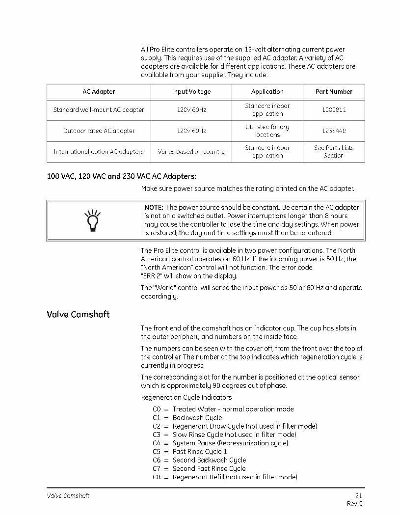
All Pro Elite controllers operate on 12-volt alternating current power
supply. This requires use of the supplied AC adapter. A variety of AC
adapters are available for different applications. These AC adapters are
available from your supplier. They include:
100 VAC, 120 VAC and 230 VAC AC Adapters:
Make sure power source matches the rating printed on the AC adapter.
The Pro Elite control is available in two power configurations. The North
American control operates on 60 Hz. If the incoming power is 50 Hz, the
"North American" control will not function. The error code
"ERR 2" will show on the display.
The "World" control will sense the input power as 50 or 60 Hz and operate
accordingly.
Valve Camshaft
The front end of the camshaft has an indicator cup. The cup has slots in
the outer periphery and numbers on the inside face.
The numbers can be seen with the cover off, from the front over the top of
the controller. The number at the top indicates which regeneration cycle is
currently in progress.
The corresponding slot for the number is positioned at the optical sensor
which is approximately 90 degrees out of phase.
Regeneration Cycle Indicators
C0 = Treated Water - normal operation mode
C1 = Backwash Cycle
C2 = Regenerant Draw Cycle (not used in filter mode)
C3 = Slow Rinse Cycle (not used in filter mode)
C4 = System Pause (Repressurization cycle)
C5 = Fast Rinse Cycle 1
C6 = Second Backwash Cycle
C7 = Second Fast Rinse Cycle
C8 = Regenerant Refill (not used in filter mode)
AC Adapter Input Voltage Application Part Number
Standard wall-mount AC adapter 120V 60HzStandard indoor
application1000811
Outdoor rated AC adapter 120V 60HzUL listed for dry
locations1235448
International option AC adapters Varies based on countryStandard indoor
application
See Parts Lists
Section
NOTE: The power source should be constant. Be certain the AC adapter
is not on a switched outlet . Power interruptions longer than 8 hours
may cause the controller to lose the time and day settings. When power
is restored, the day and time settings must then be re-entered.

22 Disinfection Of Water Conditioners
Rev C
SYSTEM DISINFECTION
Disinfection Of Water Conditioners
The materials of construction of the modern water conditioner will not
support bacterial growth, nor will these materials contaminate a water
supply. During normal use, a conditioner may become fouled with organic
matter, or in some cases with bacteria from the water supply. This may
result in an off-taste or odor in the water.
Some conditioners may need to be disinfected after installation and some
conditioners will require periodic disinfection during their normal life.
Depending upon the conditions of use, the style of conditioner, the type of
ion exchanger, and the disinfectant available, a choice can be made
among the following methods.
Sodium or Calcium Hypochlorite
Application
These materials are satisfactory for use with polystyrene resins, synthetic gel zeolite, greensand and bentonites.
5.25% Sodium Hypochlorite
These solutions are available under trade names such as Clorox*. If stronger solutions are used, such as those sold for commercial laundries, adjust the dosage accordingly.
1. Dosage
A. Polystyrene resin; 1.2 fluid ounce (35.5 mL) per cubic foot.
B. Non-resinous exchangers; 0.8 fluid ounce (23.7 mL) per cubic foot.
2. Brine tank conditioners
A. Backwash the conditioner and add the required amount of hypochlorite solution to the well of the regenerant tank. The regenerant tank should have water in it to permit the solution to be carried into the conditioner.
B. Proceed with the normal regeneration.
*Clorox is a trademark of the Clorox Company.

Disinfection Of Water Conditioners 23
Rev C
Calcium Hypochlorite
Calcium hypochlorite, 70% available chlorine, is available in several forms including tablets and granules. These solid materials may be used directly without dissolving before use.
1. Dosage
A. Two grains (approximately 0.1 ounce [3 mL]) per cubic foot.
2. Regenerant tank conditioners
A. Backwash the conditioner and add the required amount of hypochlorite to the well of the regenerant tank. The regenerant tank should have water in it to permit the chlorine solution to be carried into the conditioner.
B. Proceed with the normal regeneration.

24 Display Icons Pro Elite Control
Rev C
DETERMINING IF YOU HAVE A SILVER OR PLATINUM SERIES CONTROL
If you are unsure of your control model, simply remove the cover and disconnect the control module from the control valve. On the back of the control valve is a silver label that will show your model and version revision.
Figure 10
GENERAL PRO ELITE INSTRUCTIONS
Display Icons Pro Elite Control
Figure 11
Pentair WaterMilwaukee, WI USAAutotrol BrandModel Sensor12 V/ 60 Hz/ 4W
VERSION 1.02WO#4340000Ser. No: 716090052683-3
Model Sensor:
Silver/Platinum
Serial number with date code
g/L
PMMIN
KGx2
Time & Day
Regen Time & Day
Salt
SU MO TU WE TH FR SA DAYS
x100PHCCapacity
Hardness Lbs/ft3
1 2
3
4
5
6
7
8
9
1011
12
1314
15
16
1718
19
20
212223242526
27
28
NOTE: In normal operation and during programming, only a few of the icons will actually be displayed.
Display Icons Pro Elite Control 25
Rev C
1. Days of the week. The flag immediately below the day will appear when that day has been programmed as a day the system should regenerate (used with 7-day timer programming).
2. See #3
3. This cursor is displayed when the days between regeneration are being programmed (used with .5 to 99 day regeneration programming).
4. One of these cursors will be displayed to indicate which day will be programmed into the control.
5. "PM" indicates that the time displayed is between 12:00 noon and 12:00 midnight (there is no AM indicator). PM indicator is not used if clock mode is set to 24-hour.
6. When "MIN" is displayed, the value entered is in minute increments.
7. When g/L is displayed, the value for regenerant amount entered is in grams/Liter.
8. When "Kg" is displayed, the value entered is in kilograms or kilograins.
9. Four digits used to display the time or program value. Also used for error codes.
10. Colon flashes as part of the time display. Indicates normal operation (Silver Series only).
11. Locked/unlocked indicator. In Level I programming this is displayed when the current parameter is locked-out. It is also used in Level II programming to indicate if the displayed parameter will be locked (icon will flash) when controller is in Level I.
12. When "x2" is displayed, a second regeneration has been called for.
13. The recycle sign is displayed (flashing) when a regeneration at the next time of regeneration has been called for. Also displayed (continuous) when in regeneration.
14. The display cursor is next to "SALT" when programming the amount of regenerant. If the controller is on a 3-cycle filter then backwash time is programmed.
15. The display cursor is next to "REGEN TIME & DAY" when programming the time of regeneration and the days of regeneration.
16. The display cursor is next to "TIME & DAY" when programming the current time and day.
17. The hourglass is displayed when the motor is running. The camshaft should be turning.
18. These cursors will appear next to the item that is currently displayed.

26 Keypad — Buttons
Rev C
19. X100 multiplier for large values.
20. When Lbs/ft3 is displayed the value for regenerant amount entered is in pounds/cubic foot.
21. Faucet is displayed when the current flow rate is displayed. Control may show the faucet and "0", indicating no flow.
22. Maintenance interval display turns on if the months in service exceed the value programmed in P11.
23. Used with #24, #25, and #26. Displays a sequence number or a value.
24. History Values (H). The number displayed by #23 identifies which history value is currently displayed.
25. Parameter (P). Displayed only in Level II Programming. The number displayed by #23 identifies which parameter is currently displayed.
26. Cycle (C). The number displayed by #23 is the current cycle in the regeneration sequence.
27. Hardness setting—only used with Platinum Series controls.
28. Capacity display—shows estimated system capacity.
Keypad — Buttons
Figure 12
1. DOWN arrow. Generally used to scroll down or increment through a group of choices.
2. SET. Used to accept a setting that normally becomes stored in memory. Also used together with the arrow buttons.
3. UP arrow. Generally used to scroll up or increment through a group of choices.
2
1
3
4

Regeneration Modes 27
Rev C
4. Regenerate. Used to command the controller to regenerate. Also used to change the lock mode.
Programming Conventions
The Pro Elite control is programmed using the buttons on the keypad. The programming instructions will be described two ways whenever a section has keypad input.
First , a table shows simplified instructions. Second, text follows that describes the action. In each table:
"Action" lists the event or action desired.
"Keys" are listed as:
UP for up arrow
DOWN for down arrow
SET for set
REGEN for regeneration
"Duration" describes how long a button is held down:
P/R for press and releaseHOLD for press and holdX sec for a number of seconds to press the button and hold it down
"Display" calls out the display icons that are visible.
Regeneration Modes
The Pro Elite controls can be regenerated either automatically or manually. During a regeneration, the total time remaining of the regeneration will be displayed on the control. The current cycle is shown in the lower left of the display.
To Initiate a Manual Regeneration:
• Press REGEN once for delayed regeneration. System will regenerate at next set regen time (2:00 AM).A flashing regen (recycle) symbol will be displayed.
• Press and hold REGEN for 5 seconds to initiate immediate manual regeneration. A solid regen symbol will be displayed.
• After immediate regeneration has begun, press REGEN again to initiate a second manual regeneration. A flashing "x2" symbol indicates the second regeneration will start at the time of regeneration. Press and hold REGEN to turn on the second
NOTE: If a button is not pushed for thirty seconds, the control returns to normal operation mode. Pushing the Regenerate button immediately returns the control to normal operation.
28 Regeneration Modes
Rev C
regeneration immediately following the current regeneration. The double regeneration is indicated by the "x2" symbol being on steady.
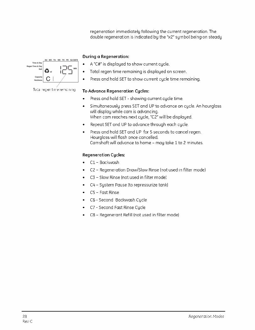
During a Regeneration:
• A "C#" is displayed to show current cycle.
• Total regen time remaining is displayed on screen.
• Press and hold SET to show current cycle time remaining.
To Advance Regeneration Cycles:
• Press and hold SET - showing current cycle time.
• Simultaneously press SET and UP to advance on cycle. An hourglass will display while cam is advancing.When cam reaches next cycle, "C2” will be displayed.
• Repeat SET and UP to advance through each cycle.
• Press and hold SET and UP for 5 seconds to cancel regen.Hourglass will flash once cancelled.Camshaft will advance to home – may take 1 to 2 minutes.
Regeneration Cycles:
• C1 – Backwash
• C2 – Regeneration Draw/Slow Rinse (not used in filter mode)
• C3 – Slow Rinse (not used in filter mode)
• C4 – System Pause (to repressurize tank)
• C5 – Fast Rinse
• C6 - Second Backwash Cycle
• C7 - Second Fast Rinse Cycle
• C8 – Regenerant Refill (not used in filter mode)
Time & Day
Regen Time & Day
Salt
SU MO TU WE TH FR SA DAYS
CCapacity
Hardness
MIN
x2
Total regen time remaining

Silver/Platinum Series Initial Power-Up 29
Rev C
Silver/Platinum Series Initial Power-Up
Initial Power Up – (Camshaft proceeds to HOME position)
• At initial power-up, the camshaft may need to rotate to the HOME (in service) position.
• Camshaft may take 1 to 2 minutes to return to HOME position.
• Err 3 will be displayed until the camshaft returns to HOME position.
• If more than 2 minutes elapses, verify that the motor is turning the camshaft. If it is not turning, contact Dealer.
Initial Start-up Step-By-Step Instructions
For FA filter applications, please program as normal below. See section Programming the 700 for 5-Cycle Filter Applications.
Step 1: Select Valve Type
This step may have been performed by your system’s OEM manufacturer. In this case, proceed to step 3.
• Identify your valve body type by looking at the silver ID sticker on the back or side of the valve body.
• Select your valve body type using the UP and DOWN buttons.
• Display Valve Body255 Not used263 Filter 263, 3-cycle filter268 Conditioner 268, 7-cycle conditioner273 Not used278 Not used293 Not used298 Not used
Time & Day
Regen Time & Day
Salt
Capacity
Hardness
SU MO TU WE TH FR SA DAYS
NOTE: The Pro Elite control features a self-test sequence. At first power-up of the control, you may see a number such as 1.00, 1.02, 1.04, or 2.00 displayed. This is an indication that the self-test is not completed. To complete the test , verify that the turbine cable is connected. Blow air into the turbine port (valve outlet) to spin the turbine. The control will verify that the turbine works and the self-test will finish. Proceed with the initial start-up procedure.

30 Initial Start-up Step-By-Step Instructions
Rev C
Step 2: Program System Size
This step may have been performed by your system’s OEM manufacturer. In this case, proceed to step 3.
• Input system size – media volume (For FA filters, choose your closest media volume) – in cubic feet or liters.
• Use UP and DOWN buttons to scroll through resin volume choices.
• Choose the nearest volume to your actual system size.
• Press SET to accept the system size you’ve selected.
• If incorrect setting is programmed, see “Resetting the Control” section
below.
Set 3: Program Time of Day
• While “12:00” is blinking, set the correct time of day.
• Use the UP and DOWN buttons to scroll to the correct time of day.
• “PM” is indicated, “AM” is not indicated.
• Press SET to accept the correct time of day and advance to the next parameter.
Step 4: Set Day of Week
• Press SET to make the arrow under “SU” flash.
• Use the UP and DOWN buttons to advance the arrow until it is under the correct day of week.
• Press SET to accept and advance to the next parameter.
After steps 1-4, the control will operate most systems. Proceed to step
5 if further adjustments to your system’s programming is needed.
Step 5: Set Regen Time
• 2:00 (AM) is the default time of regeneration. To accept this time, press the DOWN button to move to step 6.
• To change the regen time, press SET – causing “2:00” to flash.
Time & Day
Regen Time & Day
Salt
SU MO TU WE TH FR SA DAYS
Capacity
Hardness
NOTE: Capacity is the result of the amount of media in the tank and the salt setting. The default capacity will be changed by selecting a different regenerant setting.
NOTE: If the control was incorrectly set to the wrong valve body, press the DOWN button and SET button for f ive seconds to display resin volume in "HO". Press and hold the SET button for five seconds to reset the control. Use the UP or DOWN buttons to increment the display to the correct valve body. Press SET.
Time & Day
SU MO TU WE TH FR SA DAYS
Capacity
Hardness
Time & Day
Regen Time & Day
Salt
SU MO TU WE TH FR SA DAYS
Capacity
Hardness
Time & Day
Regen Time & Day
Salt
SU MO TU WE TH FR SA DAYS
Capacity
Hardness

Initial Start-up Step-By-Step Instructions 31
Rev C
• Use the UP and DOWN buttons to advance to the desired regen time.
• Press SET to accept the time and advance to the next parameter.
Step 6: Set Days to Regenerate (Silver Series Time-Clock Control Only)
• If using Platinum Series control – proceed to step 6a.
• Set number of days between time-clock regeneration (regen frequency).
• Default time is 3 days.
• Days can be adjusted from ½ (.5) to 99 days.
• To change, press SET to make the “3” flash.
• Use the UP and DOWN buttons to change the number of days desired.
• Press SET to accept the regen frequency, and advance to the next cycle.
• To use the 7-day timer option –see Dealer Installation Manual.
Step 6a: Set Calendar Override (Platinum Series Demand Control Only)
• If using Silver Series control – proceed to step 7.
• Set number of days for calendar override on demand control.
• “0” days is the default for calendar override.
• Days can be adjusted from ½ (.5) to 99 days.
• To change, press SET to make the “0” flash.
• Use the UP and DOWN buttons to change to the number of days desired. Press SET to accept the regen frequency, and advance to the next cycle.
Step 7: Amount of Regenerant used per Regeneration
If the installation is a f ilter, skip to Filter Backwash Time. The amount of
regenerant does not apply.
• Select regenerant amount.
• The default setting is 9 lbs of salt per ft3 of resin (110 grams/Liter).
• The 255 and 268 valves will follow the high eff iciency settings. See Table 1
Time & Day
Regen Time & Day
Salt
SU MO TU WE TH FR SA DAYS
Capacity
Hardness
WARNING: Silver Series Control only: Setting days between regeneration to zero will cause the system to not regenerate. This setting is used for selecting regeneration on specif ic days or to use with a remote regeneration input.
Time & Day
Regen Time & Day
Salt
SU MO TU WE TH FR SA DAYS
Capacity
Hardness

32 Initial Start-up Step-By-Step Instructions
Rev C
• To program the regenerant amount, press SET to enter the change
mode. The 9 (lbs/ft3) default will begin to flash. Use UP and DOWN to scroll through the available settings. Press SET to enter the amount.
• Filter backwash time (filter mode only)
If the system is set up as a filter, regenerant amount is unnecessary. The control deactivates the regenerant amount setting, and changes to an adjustable backwash time in minutes.
• Press SET to change the time.
• The default time of 14 minutes will begin to flash.
• Use UP and DOWN to select the appropriate backwash time for the media type and amount used. The control can use 0 to 99 minutes for backwash.
• Press SET again to enter that time.
Table 1- High Efficiency Exchange Capacity
Salt lbs/cu ft
Exchange
Capacity
grains/cu ft
Salt grams/liter
Exchange Capacity
grams/liter
3 14100 50 33.6
4 18307 60 40.0
5 21160 70 44.5
6 23490 80 48.4
7 25460 90 51.8
8 27167 100 54.9
9 28673 110 57.7
10 30019 120 60.2
11 31238 130 62.6
12 32350 140 64.8
13 33373 150 66.8
14 34320 170 70.4
15 35202 200 75.2
16 36027 230 79.3
17 36802 260 82.9
18 37533 290 86.1
Table 2
To Convert Capacity in Into Capacity in Multiply by
kilograms (kg) kilograins (kgr) 15.43
kilograins (kgr) kilograms (kg) 0.0648
moles of CaCO3 kilograms (kg) 0.10
equivalents of CaCO3 kilograms (kg) 0.05
Time & Day
Regen Time & Day
Backwash Time
SU MO TU WE TH FR SA DAYS
Capacity
Hardness

Initial Start-up Step-By-Step Instructions 33
Rev C
Step 8: Estimated Capacity
• System capacity is displayed in total kilograins or kilograms of hardness removed before a regeneration is necessary.
• Value is derived from the system’s resin volume input, and salt amount input.
• The capacity displayed is a suggested value – as recommended by resin manufacturers.
• Capacity is only displayed for information purposes on Silver Series control – it cannot be changed.
• To change capacity on Platinum Series control, press SET to make the default capacity flash. Use the UP and DOWN buttons to increment to the desired capacity.
• Press SET to accept the setting and advance to the next parameter.
• FA filters: see section on capacity, Setting the Pro Elite for 5-Cycle
Filter Applications.
If using the Silver Series control, programming is complete. The control will
return you to the normal operation mode.
Step 9: Enter Hardness (Platinum Series Demand Control Only)
• Enter inlet water hardness at installation site.
• Default hardness setting is 25 grains (25 ppm for metric).
• To change hardness, press SET to make the setting flags. Use the UP and DOWN buttons to scroll to the correct hardness.
• Press SET to accept the entered hardness value.
• The control will return you to the normal operation mode.
• FA filters: see section on capacity, Setting the Pro Elite for 5-Cycle
Filter Applications.
Initial system programming is now complete. The control will return to
normal operation mode, if a button is not pushed for 30 seconds.
Viewing Cycle Times
• Press and hold the UP and SET buttons for 3 seconds when the control is in the "in service mode" to access the "cycle time display mode". The display will show a small "c" followed by a number in the lower portion of the display.
• Press the UP and DOWN buttons to display the programmed cycle time.
• Press the REGEN button to exit the "cycle times display mode".
KG
Time & Day
Regen Time & Day
Salt
SU MO TU WE TH FR SA DAYS
Capacity
Hardness
KG
Time & Day
Regen Time & Day
Salt
SU MO TU WE TH FR SA DAYS
Capacity
Hardness

34 Initial Start-up Step-By-Step Instructions
Rev C
Adjusting Cycle Times
• Press SET when in the "cycle time display mode". The cycle time in minutes will flash, indicating the cycle time can be changed.
• Press the UP or DOWN buttons to change the flashing time.
• Press SET while the cycle time is flashing to enter the flashing value.
NOTE: The draw and refill cycle times cannot be changed in cycle time programming for conditioner valves. Draw and refill times are calculated using the draw and refill rates and salt amounts. The draw and ref ill cycle times may be programmed for 3-cycle filters.

Initial Start-up Step-By-Step Instructions 35
Rev C
PLACING CONDITIONER INTO OPERATION (turning on the water)
Start Up 268 Conditioner and FA Filter Only
After you have performed the previous initial power-up steps, you will need to place the conditioner into operation. Follow these steps carefully,
as they differ from previous Autotrol valve instructions.
1. Remove the cover from the valve. Removing the cover will allow you to see that the camshaft is turning, and in which cycle the camshaft is currently positioned.
2. With the supply water for the system still turned off, position the bypass valve to the “not in bypass” (normal operation) position.
3. Hold the REGEN button on the control down for 5 seconds. This will initiate a manual regeneration.
The control will indicate that the motor is turning the camshaft to the cycle C1 (Backwash) position by flashing an hourglass. The control will display the total regen time remaining.
If you press and hold the SET button, the control will indicate the time remaining in the current cycle.
4. Fill the media tank with water.
A. While the control is in cycle C1 (Backwash), open the water supply valve very slowly to approximately the 1/4 open position.
B. When all of the air has been purged from the media tank (water begins to flow steadily from the drain line), open the main supply valve all of the way. This will purge the final air from the tank.
C. Allow water to run to drain until the water runs clear from the drain line. This purges any refuse from the media bed.
D. Turn off the water supply and let the system stand for about five minutes. This will allow any air trapped to escape from the tank.
WARNING: Do not rotate the camshaft by hand or damage to the unit may occur. Use the control to step the camshaft electronically through the cycles.
Time & Day
Regen Time & Day
Salt
SU MO TU WE TH FR SA DAYS
CCapacity
Hardness
Flashing
WARNING: If opened too rapidly or too far, media may be lost out of the tank into the valve or the plumbing. In the 1/4 open position, you should hear air slowly escaping from the valve drain line.

36 Initial Start-up Step-By-Step Instructions
Rev C
5. Add water to the regenerant tank (initial fill) (268 conditioner and FA filters only).
A. With a bucket or hose, add approximately 4 gallons (15 liters) of water to the regenerant tank.
If the tank has a salt platform in the bottom of the tank, add water until the water level is approximately 1 inch (25 mm) above the platform.
6. Engage the refill cycle to prime the line between the regenerant tank and the valve (conditioner only).
A. Slowly open the main water supply valve again, to the fully open position. Be sure not to open too rapidly as that would push the media out of the media tank.
B. Advance the control to the Refill (C8) position. From cycle C1 (Backwash), press and hold the SET button. This will display the current cycle.
While pressing the SET button, press UP to advance to the next cycle. Continue to advance through each cycle until you have reached cycle C8 (Refill).
C. With the water supply completely open, when you arrive at cycle C8 (Refill), the control will direct water down through the line to the regenerant tank. Let the water flow through the line until all air bubbles have been purged from the line.
D. Do not let the water flow down the line to the tank for more than one to two minutes, or the tank may overfill.
E. Once the air is purged from the line, press the SET button and the UP button simultaneously to advance to cycle C0 (Treated Water) position.
NOTE: We recommend that you do not put regenerant into the tank until after the control valve has been put into operation. With no regenerant in the tank, it is much easier to view water flow and motion in the tank.
NOTE: As you advance through each cycle there will be a slight delay before you can advance to the next cycle. The hourglass icon will light while the camshaft is indexing. There may be a pause at cycle C4 (System Pause). This cycle allows the water/air pressure to equalize on each side of the valve discs before moving on. The hourglass will not be visible indicating that the system is paused.
Time & Day
Regen Time & Day
Salt
SU MO TU WE TH FR SA DAYS
CCapacity
Hardness

Initial Start-up Step-By-Step Instructions 37
Rev C
7. Draw water from the regenerant tank.
A. From the treated water position (cycle C0), advance the valve to the draw regenerant position. Hold the REGEN button down for five seconds.
The control will begin a manual regen, and advance the control valve to the cycle C1 (Backwash). Press the SET and UP button to advance to cycle C2 (Draw).
B. With the control in this position, check to see that the water in the regenerant tank is being drawn out of the tank. The water level in the tank should recede very slowly.
C. Observe the water being drawn from the regenerant tank for at least three minutes. If the water level does not recede, or goes up, check all hose connections. C2 should be displayed.
8. If the water level is receding from the regenerant tank you can then advance the control back to the treated water (C0) position by pressing SET and the UP buttons simultaneously to advance the control to the C0 position.
9. Finally, turn on a faucet plumbed after the water conditioner. Run the faucet until the water runs clear.

38 Manganese Greensand Systems
Rev C
PROGRAMMING THE PRO ELITE FOR 5-CYCLE FILTER APPLICATIONS
Manganese Greensand Systems
Sizing FA Filters
Potassium permanganate regenerating iron filters should be sized for the
appropriate backwash and injector sizes.
Backwash Control
Be sure to choose the appropriate backwash flow rate control (see Parts
section) as recommended by your media manufacturer.
Injector
Use the same injector size as you would for your conditioner control tank
diameter.
Refill Control
An FA filter can use the 0.33 gpm refill control that is featured as standard
with the Pro Elite control. Use a check valve in your potassium
permanganate feeder to prevent overflow.
Initial Resin Volume Setting
Programming for a manganese greensand system requires a few minor
adjustments to the programming to operate the control correctly. The
initial resin volume should be set to the closest volume of the manganese
greensand in the system. For example, if the system contains two cubic
feet of manganese greensand, program in 2.00 for the resin volume.
"Salt" Setting for KMNO3 Regenerant
Be sure the regenerant (salt setting) is set high enough to operate the float
shut off in the regenerant storage tank.
All other settings will remain the same as mentioned in the previous
programming sections.
Days Between Regeneration Setting (Silver Series FA)
To set the days between regenerations, consult the media manufacturer
for the actual capacity of the media.
In general, manganese greensand has a capacity of 10,000 ppm of
removal capability per cubic foot of media. Calculate the capacity of the
system by taking the number of cubic feet of media and multiply by
10,000.
For example, using a 1 cubic foot system provides 10,000 ppm of removal
capability.
The next step is to calculate the demand for the system. Multiply the
predicted daily water usage by the iron content in ppm.

Manganese Greensand Systems 39
Rev C
For example, an average person uses 75 gallons of water per day. Four people living in a home use 300 gallons of water (75 gallons x 4 people) per day. Assume the incoming water has 10 ppm of iron. Now calculate the daily demand: multiply the gallons of water used per day (300) by the ppm of iron content (10) = 3000 ppm of daily capacity usage.
Now take the system capacity (10,000), divided by the daily demand (3,000) = 3.3 days of capacity. Since you will run out of capacity before the beginning of the fourth day, the proper setting for days between regeneration is 3 days.
For example:
4 people x 75 gals per person = 300 gallons used per day.
10 ppm iron x 300 gal/day = 3000 ppm/day
10,000 ppm capacity ÷ 3000 ppm/day = 3.3 days of total capacity
Solution = regenerate every 3 days.
Volume/Demand Regeneration Setting
To set a Platinum Series demand system for iron removal you must:
• Know your media capacity. Generally, one cubic foot of magnesium greensand can remove 10,000 ppm of iron.
• Know the iron concentration in your water.
To have your system regenerate on demand, set your system’s capacity (P7) to the appropriate factor. On the Platinum Series control, it will read Kg, but you will actually be working in ppm of iron.
• If your system is one cubic foot, set the capacity to "10" kg, meaning 10,000. For two cubic feet , set the capacity to "20" kg.
• Set your hardness to the level of ppm iron in your water. If you have 3 ppm of iron, set the Platinum Series control to "3".
• The control will calculate the remaining volume capacity in gallons
(m3) and count down to regeneration.
Time & Day
Regen Time & Day
Salt Amount
SU MO TU WE TH FR SA DAYS
Capacity
Hardness
KG
Time & Day
Regen Time & Day
Salt Amount
SU MO TU WE TH FR SA DAYS
Capacity
Hardness

40 Things You Might Need to Know
Rev C
Things You Might Need to Know
• When the control is f irst plugged in, it may display a flashing hourglass and the message Err 3, this means that the controller is rotating to the home position. If the Err 2 is displayed, check that the incoming power frequency matches the controller. The North American control will not run with 50 Hz input.
• The preset default time of regeneration is 2:00 AM.
• English or Metric? The World control senses the electrical input and decides which is needed. The North American control only runs on 60 Hz and defaults to English units.
• The Pro Elite control can be programmed to regenerate on specific days of the week.
• If electrical power is not available, the camshaft can be rotated counterclockwise by hand if the motor is removed.
• The Pro Elite controls send commands to the motor for camshaft movement. However, water pressure/flow are required during the regeneration cycle for backwash, purge and ref ill, and brine draw to actually take place.
• Make sure control power source is plugged in. The transformer should be connected to a non-switched power source.
• You can start programming at the beginning by resetting the control mode. When viewing H0 (History Value) push and hold SET for five seconds. The display reverts back to 255 and any programmed information is lost . Return to Pro Elite Initial Power Up.
SILVER/PLATINUM SERIES ADVANCED PROGRAMMING 41
Rev C
SILVER/PLATINUM SERIES ADVANCED PROGRAMMING
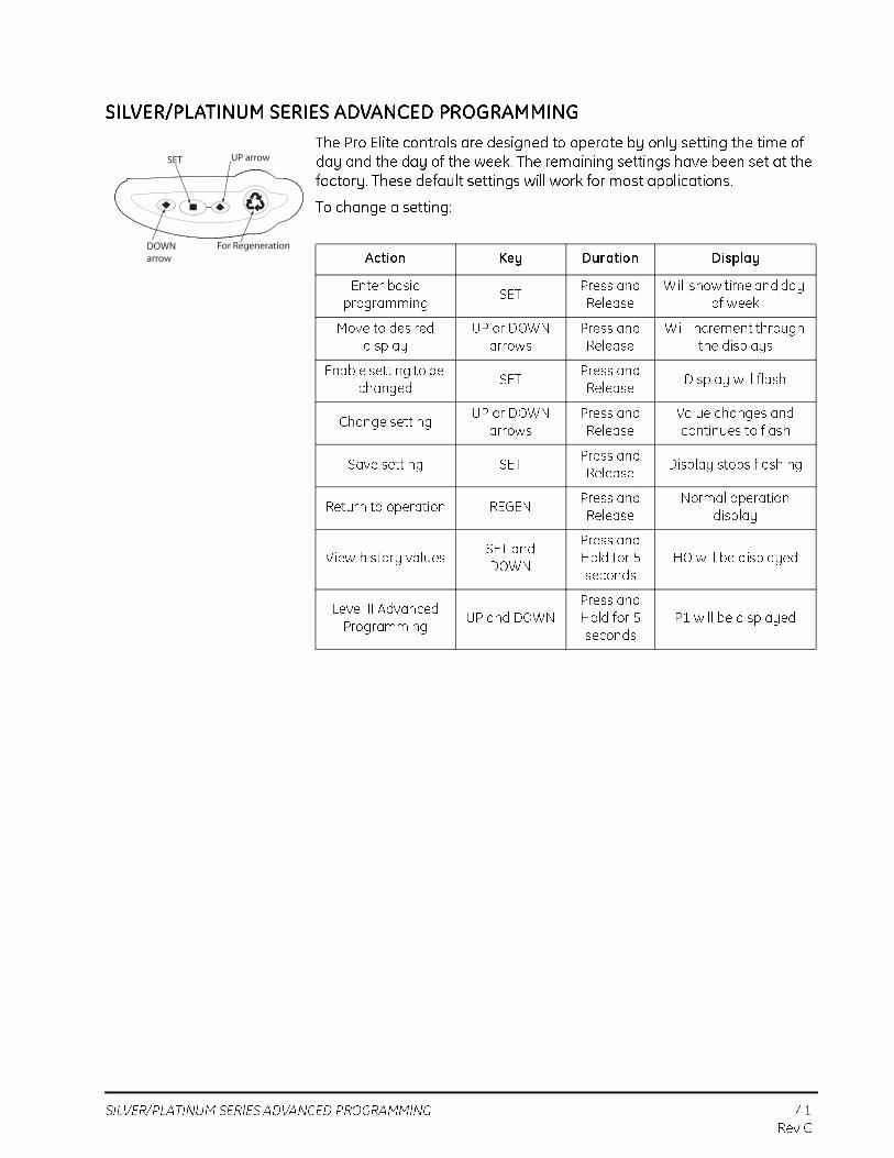
The Pro Elite controls are designed to operate by only setting the time of day and the day of the week. The remaining settings have been set at the factory. These default settings will work for most applications.
To change a setting:
Action Key Duration Display
Enter basic
programmingSET
Press and
Release
Will show time and day
of week
Move to desired
display
UP or DOWN
arrows
Press and
Release
Will increment through
the displays
Enable setting to be
changedSET
Press and
ReleaseDisplay will flash
Change setting UP or DOWN
arrows
Press and
Release
Value changes and
continues to flash
Save setting SETPress and
ReleaseDisplay stops flashing
Return to operation REGENPress and
Release
Normal operation
display
View history valuesSET and
DOWN
Press and
Hold for 5
seconds
HO will be displayed
Level II Advanced
ProgrammingUP and DOWN
Press and
Hold for 5
seconds
P1 will be displayed
For Regeneration
SET UP arrow
DOWNarrow

42 SILVER/PLATINUM SERIES LEVEL II PROFESSIONAL PRO-
GRAMMING
SILVER/PLATINUM SERIES LEVEL II PROFESSIONAL PROGRAMMING
The Silver/Platinum Series features a special programming level that allows the installing dealer to make changes to the control for more demanding applications. The home owner/end user should never have to access this level.
To enter Level II programming press and hold UP and DOWN for 5 seconds. A "P" value will be displayed indicating Level II.
Level II menus include:
P1 = Time of day
P2 = Day of week
P3 = Time of regeneration
P4 = Number of days between regeneration (99 day calendar override)
P5 = Not used (Silver Series only)
P6 = Amount of regenerant used per regeneration or filter backwash time (salt setting)
P7 = System capacity
P8 = Hardness
P9 = Units of measure
P10 = Clock mode
P11 = Service interval
P12 = Remote regeneration switch delay
P13 = Refill sensor control (conditioner only)
0 = Off1 = Salt detector only2 = Chlorine generation
P14 = Refill rate (conditioner only)
P15 = Draw rate (conditioner only)
P16 = Reserve type
P17 = Initial average or f ixed reserve
P18 = Flow sensor select
P19 = K-factor or pulse equivalent
See the Professional dealers manual for further details on setting Level II parameters.
Time & Day
Regen Time & Day
Salt Amount
SU MO TU WE TH FR SA DAYS
PCapacity
Hardness
P Value
Accessing History Values 43
Rev C
Accessing History Values
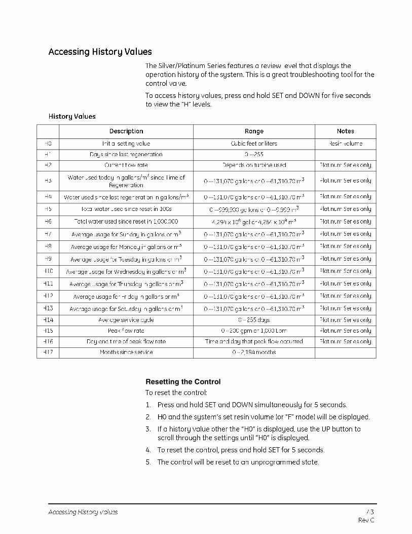
The Silver/Platinum Series features a review level that displays the operation history of the system. This is a great troubleshooting tool for the control valve.
To access history values, press and hold SET and DOWN for five seconds to view the "H" levels.
History Values
Resetting the Control
To reset the control:
1. Press and hold SET and DOWN simultaneously for 5 seconds.
2. H0 and the system’s set resin volume (or “F” mode) will be displayed.
3. If a history value other the “H0” is displayed, use the UP button to scroll through the settings until “H0” is displayed.
4. To reset the control, press and hold SET for 5 seconds.
5. The control will be reset to an unprogrammed state.
Description Range Notes
H0 Initial setting value Cubic feet or liters Resin volume
H1 Days since last regeneration 0 – 255
H2 Current flow rate Depends on turbine used Platinum Series only
H3 Water used today in gallons/m3 since Time of Regeneration
0 – 131,070 gallons or 0 – 61,310.70 m3 Platinum Series only
H4 Water used since last regeneration in gallons/m3 0 – 131,070 gallons or 0 – 61,310.70 m3 Platinum Series only
H5 Total water used since reset in 100s 0 – 999,900 gallons or 0 – 9,999 m3 Platinum Series only
H6 Total water used since reset in 1,000,000 4,294 x 106 gal or 4,264 x 104 m3 Platinum Series only
H7 Average usage for Sunday in gallons or m3 0 – 131,070 gallons or 0 – 61,310.70 m3 Platinum Series only
H8 Average usage for Monday in gallons or m3 0 – 131,070 gallons or 0 – 61,310.70 m3 Platinum Series only
H9 Average usage for Tuesday in gallons or m3 0 – 131,070 gallons or 0 – 61,310.70 m3 Platinum Series only
H10 Average usage for Wednesday in gallons or m3 0 – 131,070 gallons or 0 – 61,310.70 m3 Platinum Series only
H11 Average usage for Thursday in gallons or m3 0 – 131,070 gallons or 0 – 61,310.70 m3 Platinum Series only
H12 Average usage for Friday in gallons or m3 0 – 131,070 gallons or 0 – 61,310.70 m3 Platinum Series only
H13 Average usage for Saturday in gallons or m3 0 – 131,070 gallons or 0 – 61,310.70 m3 Platinum Series only
H14 Average service cycle 0 - 255 days Platinum Series only
H15 Peak flow rate 0 - 200 gpm or 1,000 Lpm Platinum Series only
H16 Day and time of peak flow rate Time and day that peak flow occurred Platinum Series only
H17 Months since service 0 - 2,184 months

44 Accessing History Values
Rev C
6. Go to “Initial Set-up” section to reprogram control.
WARNING: Resetting the control will delete all information stored in its
memory, except time and day. This will require you to reprogram the control
completely from the initial power-up mode.

Valve Exploded View 45
Rev C
PARTS AND ACCESSORIES
Valve Exploded View
2
1
3
4
5
6
7
8
910
11
12
13
14
16
15
17
18
19
11

46 Valve Parts List
Rev C
Valve Parts List
*Not shown on drawing.
Code
Part
No. Description Qty. Code
Part
No. Description Qty.1 1244652 Valve Assembly w/o Flow Controls 1 10 1243510 Regenerant Refill Control, 0.33 gpm
2 1235338 Top Plate 1 11 1030502 Ball, Flow Control 1
3 1235339 Valve Disc Spring, One Piece, Valve 1 * 1030334 Plugged Refill Flow Control
12 1002449 Drain Fitting Elbow (3/4-inch hose barbed) 1
4 3022113 Cover, Valve, w/Insert , Pro Elite 1 13 1010428 O-Ring 1
14 1000269 Injector Cap with O-Ring 1
5 1235352 Cam, Pro Elite Valve, STD, Black 1 15 1035622 Tank Ring 1
6 Drain Control Assembly: 1 * 1041174 Valve Disc Kit: Standard
1000209 No. 7 (1.3 gpm; 4.9 Lpm) 16 Plumbing Adapter Kits: 1
1000210 No. 8 (1.7 gpm; 6.4 Lpm) 1001606 3/4-inch Copper Tube Adapter Kit
1000211 No. 9 (2.2 gpm; 8.3 Lpm) 1001670 1-inch Copper Tube Adapter Kit
1000212 No. 10 (2.7 gpm; 10.2 Lpm) 1001608 22-mm Copper Tube Adapter Kit
1000213 No. 12 (3.9 gpm; 14.76 Lpm) 1001613 3/4-inch CPVC Tube Adapter Kit
1000214 No. 13 (4.5 gpm; 17 Lpm) 1001614 1-inch CPVC Tube Adapter Kit
1000215 No. 14 (5.3 gpm; 20 Lpm) 1001615 25-mm CPVC Tube Adapter Kit
* 1239760 Blending Valve Kit Pro Elite Top Plate 1001769 3/4-inch NPT Plastic Pipe Adapter Kit
* Drain Line Flow Control (External) 1001603 1-inch NPT Plastic Pipe Adapter Kit
1030355 Drain Line Flow Control, 5 gpm (19 Lpm) 1001604 3/4-inch BSPT Plastic Pipe Adapter Kit
1030356 Drain Line Flow Control, 6 gpm (22.5 Lpm) 1001605 1-inch BSPT Plastic Pipe Adapter Kit
1030357 Drain Line Flow Control, 7 gpm (26.5 Lpm) 1001611 3/4-inch BSPT Brass Pipe Adapter Kit
1030358 Drain Line Flow Control, 8 gpm (30 Lpm) 1001610 1-inch NPT Brass Pipe Adapter Kit
1030359 Drain Line Flow Control, 9 gpm (34 Lpm) 1001612 1-inch BSPT Brass Pipe Adapter Kit
1030360 Drain Line Flow Control, 10 gpm (38 Lpm) 17 1235361 Motor w/Spacer & Pinion, Pro Elite Control, 1
7 1235369 Motor/Optical Cable Assembly Pro Elite 1 12 V, 50/60 Hz
Controller/Module, Sensor, Photo Interrupter 18 1001986 13/16 inch Rubber Insert (Optional) 1
8 1000226 Screen/Cap Assembly w/ O-Ring 1 19 1235446 Turbine Cable 1
9 1035732 “G” Injector (High Efficienty) - Tan 1 * 1010154 Tank O-Ring 1
(8-inch tank) * 1033444 Internal Turbine Meter
1035733 “H” Injector (High Efficiency) - Lt Purple * 1233187 Motor Locking Pin
(9-inch tank) * 1299336 Chlorine Generator Kit
1035734 “J” Injector (High Efficiency) - Lt Blue * 1033444 Turbine Assembly
(10-inch tank) * 1041174 Valve Disc Kit , Standard
1035735 “K” Injector (High Efficiency) - Pink * 1239979 Cable Harness, Remote Regen Silver Series Filter
(12-inch tank) * 1239711 Switch Kit , Front Mount, 0.1 amp
1035736 “L” Injector (High Efficienncy) - Orange * 1239752 Switch Kit , Front Mount 5 amp
(13 & 14-inch tanks) * 1239753 Switch Kit , Top Plate Mount, 0.1 amp
1032978 Plugged Injector for 263 Filter * 3022110 Skirt
1032985 Plugged Injector Cap

Pro Elite Control Parts List 47
Rev C
Pro Elite Control Parts List
Silver/Platinum Control
Time & Day
Regen Time & Day
Salt
SU MO TU WE TH FR SA DAYS
LBS
PMMIN
KG
x100x2
PHC
Capacity
Hardness
AC Adapter
Time/Day
Su Mo Tu We Th Fr Sa DAYS
Regeneration Time/DaySalt Amount
Control Overlays
Code
Part
No. Description Qty. Code
Part
No. Description Qty.Electronics Modules/Controllers 1 AC Adapter
1242150 Silver Series Control 1000810 Japanese
1242162 Silver Series F Control 1000811 North American
1242168 Platinum Series Control 1000812 Australian
1242170 Platinum Series F Control 1000813 British
Electrical Components 1000814 European
1235269 Motor/Opticla Cable Assembly, Pro Elite 1030234 Transformer Extension Cord 15 foot (4.5m)
Control 1235448 North American Outdoor AC Adapter
1235373 Module, Sensor, Photo Interrupter Overlays
1235361 Motor w/Spacer & Pinion, Pro Elite
Control 12V, 50/60 Hz
1244336 Refill Sensor Probe for Salt Detector
Applications
1256257 Remote Mount Kit

48 Pro Elite Control Parts List
Rev C
TROUBLESHOOTING
Pro Elite Control Troubleshooting
Problem Possible Cause Solution
ERR 1 is displayed Control power has been connected and
the control is not sure of the state of the
operation.
Press the UP arrow and the control
should reset.
ERR 2 is displayed Control power does not match 50 or 60
Hz.
Disconnect and reconnect the power.
If problem persists, obtain the
appropriate control or AC adapter for
either 50 or 60 Hz power.
ERR 3 is displayed Control does not know the position of the
camshaft . Camshaft should be rotating
to find Home position.
Wait for two minutes for the control to
return to Home position. The hourglass
should be flashing on the display
indicating the motor is running.
Camshaft is not turning during ERR 3
display.
Check that motor is connected.
Verify that motor wire harness is
connected to motor and control module.
Verify that optical sensor is connected
and in place.
Verify that motor gear has engaged cam
gear.
If everything is connected, try replacing
in this order:
—Wire harness
—Motor
—Optical sensor
—Control
If camshaft is turning for more than five
minutes to find Home position:
Verify that optical sensor is in place and
connected to wire.
Verify that camshaft is connected
appropriately.
Verify that no dirt or rubbish is clogging
any of the cam slots.
If motor continues to rotate indefinitely,
replace the following components in this
order:
—Wire harness
—Motor
—Optical sensor
—Control
Four dashes displayed:
— — : — —
Power failure occurred Press SET to reset the time display.

Pro Elite Control Parts List 49
Rev C
System Troubleshooting
Problem Possible Cause Solution
1. Brine tank overflow.
a. Uncontrolled brine refill flow rate.
b. Drain control clogged with resin or other debris.
a. Remove brine control to clean ball and seat.
b. Clean drain control.
2. Flowing or dripping water at drain or brine line after regeneration.
a. Valve stem return spring weak.
b. Debris is preventing valve disc from closing.
a. Replace spring. (Contact dealer.)
b. Remove debris.
3. Hard water leakage after regeneration.
a. Improper regeneration.
b. Leaking of external bypass valve.
c. O-ring around riser pipe damaged.
d. Incorrect capacity.
a. Repeat regeneration after making certain correct salt dosage was set .
b. Replace bypass valve. (Contact dealer.)
c. Replace O-ring. (Contact dealer.)
d. Verify appropriate salt amount and system capacity. (Contact dealer.)
4. Control will not draw brine.
a. Low water pressure.
b. Restricted drain line.
c. Injector plugged.
d. Injector defective.
e. Valve disc 2 and/or 3 not closed.
f. Air check valve prematurely closed.
a. Make correct setting according to instructions.
b. Remove restriction.
c. Clean injector and screen.
d. Replace injector and cap. (Contact dealer.)
e. Remove foreign matter from disc and check disc for closing by pushing in on stem. Replace if needed. (Contact dealer.)
f. Put control momentarily into brine refill, C8. Replace or repair air check if needed. (Contact dealer.)
5. Control will not regenerate automatically.
a. AC adapter or motor not connected.
b. Defective motor.
a. Connect power.
b. Replace motor. (Contact dealer.)
6. Control regenerates at wrong time of day.
a. Controller set incorrectly. a. Correct time setting according to instructions.
7. Valve will not draw brine.
a. Low water pressure.
b. Restricted drain line.
c. Injector plugged.
d. Injector defective.
a. Set pump to maintain 20 psi at softener.
b. Change drain to remove restriction.
c. Clean injector and screen.
d. Replace injector. (Contact dealer.)
8. System using more or less salt than regenerant setting.
a. Foreign matter in valve causing incorrect flow rates.
a. Remove brine control and flush out foreign matter. Advance control to brine/slow rinse, C2 to clean valve (after so doing position control to "fast rinse, C7” to remove regenerant from tank).
9. Intermittent or irregular regenerant draw.
a. Low water pressure.
b. Defective injector.
a. Set pump to maintain 20 psi at conditioner.
b. Replace injector. (Contact dealer.)
50 Pro Elite Control Parts List
Rev C
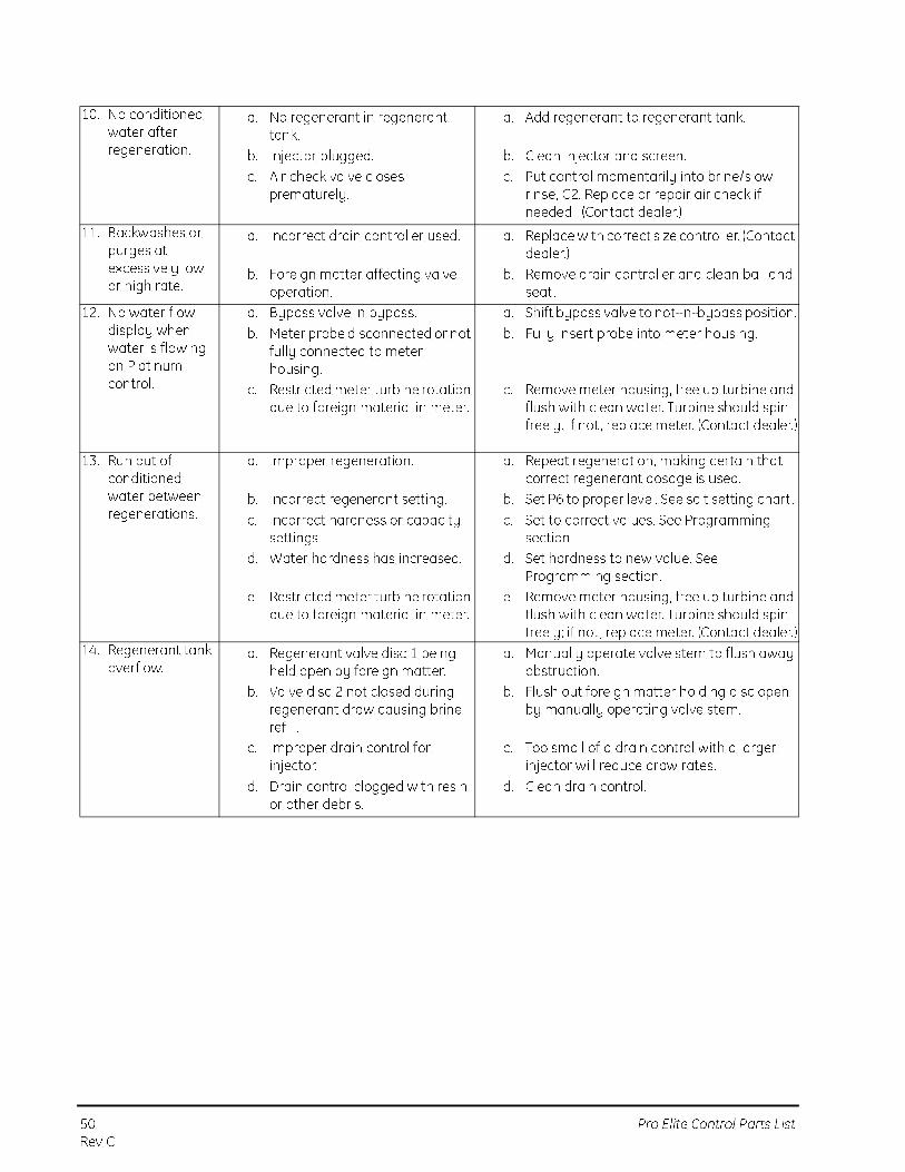
10. No conditioned water after regeneration.
a. No regenerant in regenerant tank.
b. Injector plugged.
c. Air check valve closes prematurely.
a. Add regenerant to regenerant tank.
b. Clean injector and screen.
c. Put control momentarily into brine/slow rinse, C2. Replace or repair air check if needed. (Contact dealer.)
11. Backwashes or purges at excessively low or high rate.
a. Incorrect drain controller used.
b. Foreign matter affecting valve operation.
a. Replace with correct size controller. (Contact dealer.)
b. Remove drain controller and clean ball and seat.
12. No water flow display when water is flowing on Platinum control.
a. Bypass valve in bypass.
b. Meter probe disconnected or not fully connected to meter housing.
c. Restricted meter turbine rotation due to foreign material in meter.
a. Shift bypass valve to not-in-bypass position.
b. Fully insert probe into meter housing.
c. Remove meter housing, free up turbine and flush with clean water. Turbine should spin freely. If not , replace meter. (Contact dealer.)
13. Run out of conditioned water between regenerations.
a. Improper regeneration.
b. Incorrect regenerant setting.
c. Incorrect hardness or capacity settings.
d. Water hardness has increased.
e. Restricted meter turbine rotation due to foreign material in meter.
a. Repeat regeneration, making certain that correct regenerant dosage is used.
b. Set P6 to proper level. See salt setting chart .
c. Set to correct values. See Programming section.
d. Set hardness to new value. See Programming section.
e. Remove meter housing, free up turbine and flush with clean water. Turbine should spin freely; if not , replace meter. (Contact dealer.)
14. Regenerant tank overflow.
a. Regenerant valve disc 1 being held open by foreign matter.
b. Valve disc 2 not closed during regenerant draw causing brine refill.
c. Improper drain control for injector.
d. Drain control clogged with resin or other debris.
a. Manually operate valve stem to flush away obstruction.
b. Flush out foreign matter holding disc open by manually operating valve stem.
c. Too small of a drain control with a larger injector will reduce draw rates.
d. Clean drain control.

Pro Elite Control Parts List 51Rev C

© 2009 Pentair Residential Filtration, LLCP/N 3022430 Rev. C MA09