Embed Size (px)
Citation preview

Product Data
40MHHHigh Wall Ductless SystemSizes 09 to 24
INDUSTRY LEADING FEATURES / BENEFITS
A PERFECT BALANCE BETWEENBUDGET LIMITS, ENERGY SAVINGS ANDCOMFORT.The 40MHH series ductless systems are a matched combination ofan outdoor condensing unit and an indoor fan coil unit connectedonly by refrigerant tubing and wires.
The fan coil is mounted on the wall, near the ceiling. This selectionof fan coils permits creative solutions to design problems such as:
� Add−ons to current space (an office or family roomaddition)
� Special space requirements
� When changes in the load cannot be handled by theexisting system
� When adding air conditioning to spaces that are heatedby hydronic or electric heat and have no ductwork
� Historical renovations or any application wherepreserving the look of the original structure is essential.
The ideal compliment to your ducted system when it is impracticalor prohibitively expensive to use ductwork.These compact indoor fan coil units take up very little space in theroom and do not obstruct windows. The fan coils are attractivelystyled to blend with most room decors. Advanced systemcomponents incorporate innovative technology to provide reliablecooling performance at low sound levels.

2
LOW SOUND LEVELSWhen noise is a concern, the ductless systems are the answer. Theindoor units are whisper quiet. There are no compressors indoors,either in the conditioned space or directly over it, and there isnone of the noise usually generated by air being forced throughductwork.
SECURE OPERATIONIf security is an issue, outdoor and indoor units are connected onlyby refrigerant piping and wiring to prevent intruders from crawlingthrough ductwork. In addition, since the outdoor units can beinstalled close to an outside wall, coils are protected from vandalsand severe weather.
FAST INSTALLATIONThis compact ductless system is simple to install. A mountingbracket is standard with the indoor units and only wire and pipingneed to be run between the indoor and outdoor units. These unitsare fast and easy to install ensuring minimal disruption tocustomers in the home or workplace. This makes the ductlesssystems the equipment of choice, especially in retrofit situations.
SIMPLE SERVICING AND MAINTENANCERemoving the top panel on outdoor units provides immediateaccess to the control compartment, providing a service technicianaccess to check unit operation. In addition, the draw−thru design ofthe outdoor section means that dirt accumulates on the outsidesurface of the coil. Coils can be cleaned quickly from the insideusing a pressure hose and detergent.On all indoor units, service and maintenance expense is reduceddue to easy−to−use cleanable filters. In addition, these high wallsystems have extensive self−diagnostics to assist introubleshooting.
BUILT−IN RELIABILITYDuctless system indoor and outdoor units are designed to provideyears of trouble−free operation.The high wall indoor units include protection against freeze−upand high evaporator temperatures on heat pumps.The condensing units on heat pumps are protected by a threeminute time delay before the compressor starts the over−currentprotection and the high temperature protection.
INDIVIDUAL ROOM COMFORTMaximum comfort is provided because each space can becontrolled individually based on usage pattern. The air sweepfeature provided permits optimal room air mixing to eliminate hotand cold spots for occupant comfort. In addition, year−roundcomfort can be provided with heat pumps.
ECONOMICAL OPERATIONThe ductless system design allows individual room heating orcooling when required. There is no need to run large supply−airfans or chilled water pumps to handle a few spaces with uniqueload patterns. In addition, because air is moved only in the spacerequired, no energy is wasted while air moves through the ducts.
EASY−TO−USE CONTROLSThe high wall units have microprocessor−based controls to providethe ultimate in comfort and efficiency. The user friendly wirelessremote control provides the interface between the user and the unit.
ACCESSORIESCustomizing these ductless systems to your application is easilyaccomplished.Adding a condensate pump accessory to the high wall fan coilprovides installation flexibility.
OPTIONAL WIRED CONTROLLER
AGENCY LISTINGSAll systems are listed with AHRI (Air Conditioning, Heating &Refrigeration Institute), and ETL.

3
MODEL NUMBER NOMENCLATURE
QH
SYSTEM TYPEH = COOLING ONLYQ = HEAT PUMP
INDOOR FAN COIL TYPEH = HIGH WALL
NOT USED
INDOOR UNIT
40 MH 309
40= FAN COIL UNIT
MH = MODEL
VOLTAGE1 =115-1-603 = 208/230-1-60
NOMINAL CAPACITY09 - 3/4 TON12 - 1 TON18 - 1-1/2 TONS 24 - 2 TONS
NOT USED
- --
Use of the AHRI CertifiedTM Mark indicates amanufacturer’s participation in the program For verification of certification for individual products, go to www.ahridirectory.org.

4
STANDARD FEATURES AND ACCESSORIESEase Of Installation
Mounting Brackets S
Low Voltage Controls S
Comfort Features
Microprocessor Controls S
Wired Remote Control A
Wireless Remote Control S
Automatic Up-Down Airflow Louver Swing S
Air Direction Control S
Auto Restart Function S
Cold Blow Protection On Heat Pumps S
Freeze Protection Mode On Heat Pumps S
Turbo Mode S
Silence Mode S
Auto Changeover On Heat Pumps S
Follow Me SEnergy Saving Features
Sleep Mode S
Stop/Start Timer S
46°F Heating Mode (Heating Setback) SSafety And Reliability
Indoor Coil Freeze Protection S
Indoor Coil High Temp Protection in Heating Mode S
Ease Of Service And Maintenance
Cleanable Filters S
Diagnostics S
Application Flexibility
Condensate Pumps ALegendS StandardA Accessory
ACCESSORIES
ACCESSORY NO. DESCRIPTION FOR MODELS
53DS-900---117CONDENSATE PUMP
(115V)SIZES 09, 12 (115V)
53DS-900---118CONDENSATE PUMP
(208-230V)SIZES 09, 12, 18, 24,
(208-230V)
KSACN0401AAAWIRED REMOTE
CONTROLALL SIZES
53DS-900---089INSULATED 25’ LINE
SET - 1/4” X 3/8”SIZE 09
53DS-900---008INSULATED 25’ LINE
SET - 1/4“ X 1/2”SIZES 12, 18
INDOOR UNITS
Fig. 1 – Condensate Pump AccessoryOn high wall fan coils, the condensate pump has a lift capabilityof 12 ft. (3.6 m) on the discharge side with the pump mounted inthe fan coil or 6 ft. (1.8 m) on the suction side if the pump isremote mounted. The pump is recommended when an adequatedrain line pitch cannot be provided, or when the condensate mustmove up to exit.NOTE: An external 115v power source is required to run thepump on unit sizes 9k and 12k.

5
DIMENSIONS − INDOORHIGH WALL UNIT SIZE 9K 12K 9K 12K 18K 24K
Voltage (115V) (115V) (208/230V) (208/230V) (208/230V) (20/230V)
Height In. (mm) 11.81(300) 11.81(300) 11.81(300) 11.81(300) 12.8(325) 13.41(341)
Width In. (mm) 28.53(725) 32.00(813) 28.53(725) 32.00(813) 38.36(974) 43.83(1113)
Depth In. (mm) 7.75(197) 7.75(197) 7.75(197) 7.75(197) 8.87(225) 9.22(234)
Weight-Net(Cooling Only)
Lbs (kg) 16.53(7.5) 17.64(8) 16.53(7.5) 17.64(8) 23.15(10.5) 30.86(14)
Weight-Net(Heat Pump)
Lbs (kg) 21.83(9.9) 22.49(10.2) 21.16 (9.6) 22.49(10.2) 31.97(14.5) 40.12(18.2)
Units: Inches [mm]
Fig. 2 – Size 9K

6
DIMENSIONS − INDOOR (CONT)
Units: Inches [mm]
Fig. 3 – Size 12K
7
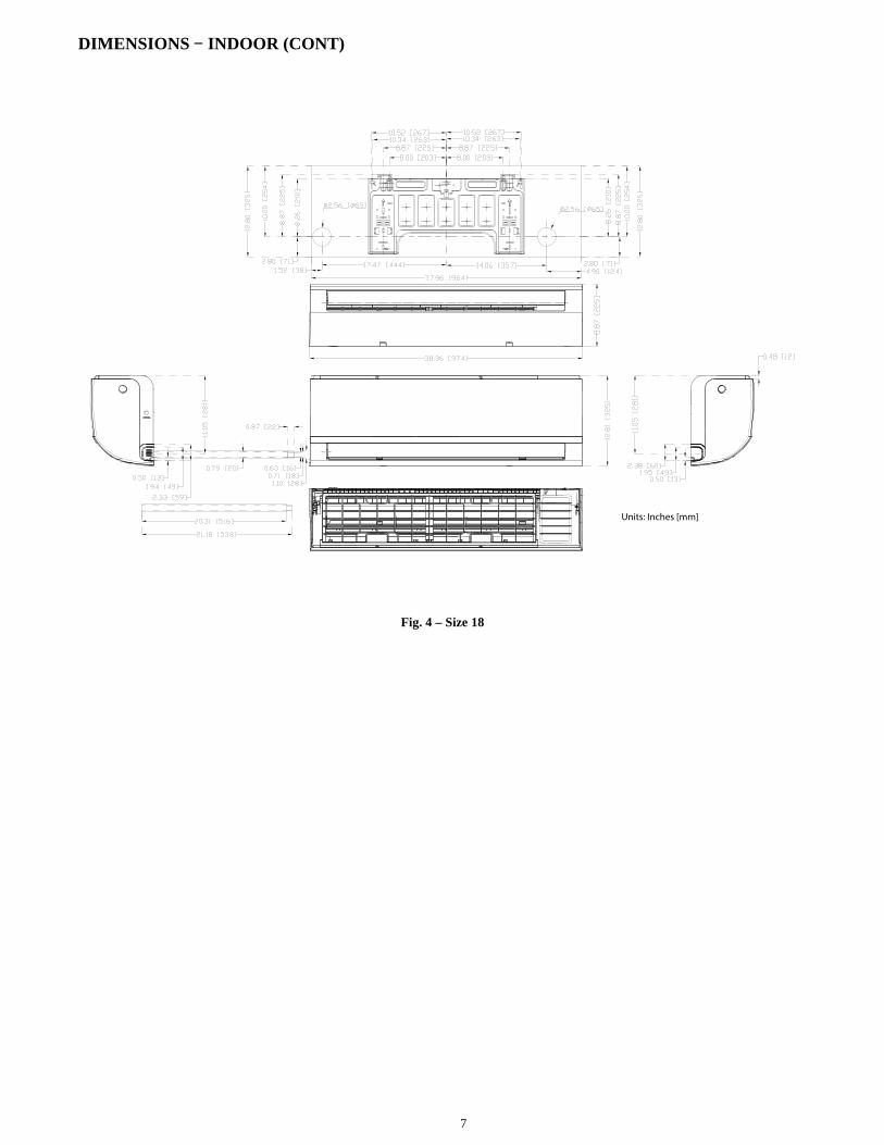
DIMENSIONS − INDOOR (CONT)
Units: Inches [mm]
Fig. 4 – Size 18
8
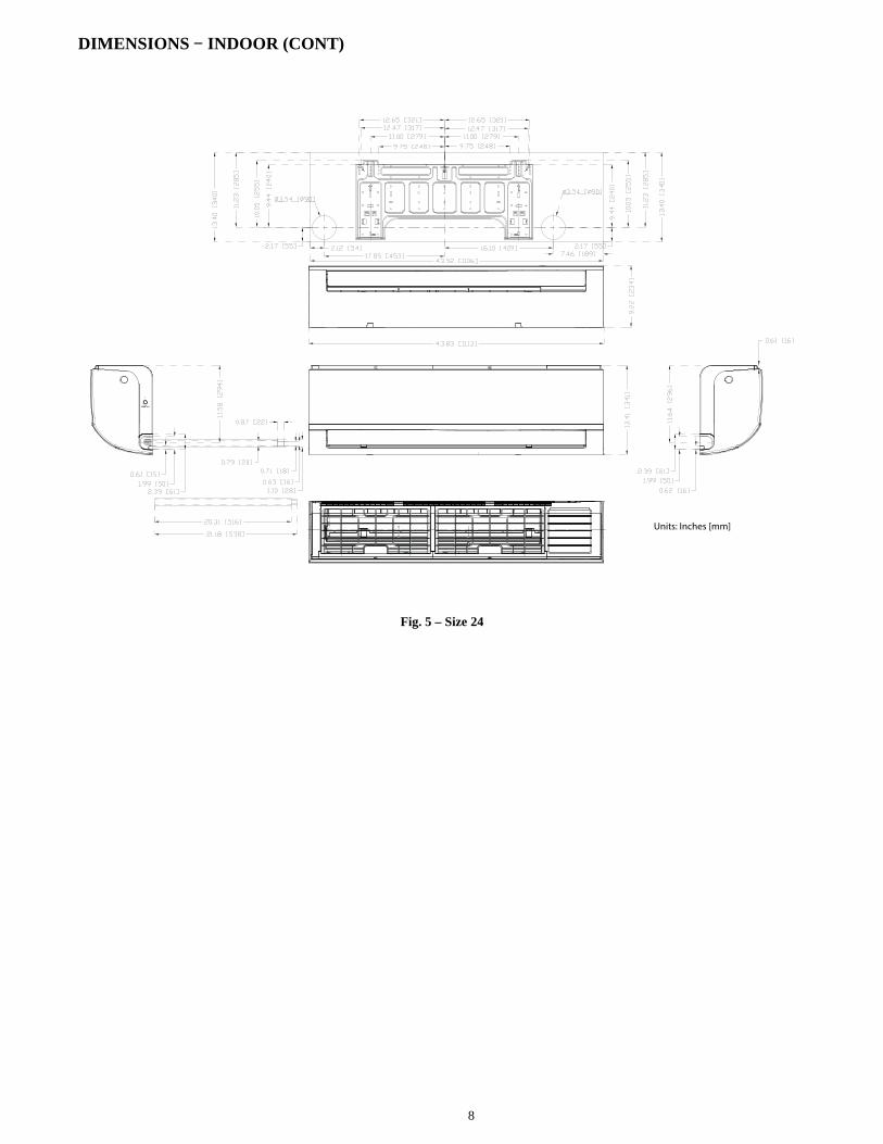
DIMENSIONS − INDOOR (CONT)
Units: Inches [mm]
Fig. 5 – Size 24

9
CLEARANCES − INDOOR
6" (0.15m) min.
5"(0.13m)
min.
6'
5"(0.13m)
min.
(1.8m)
CEILING
FLOOR
Fig. 6 – Indoor Unit Clearance

10
SPECIFICATIONS − COOLING ONLY
COOLING ONLY
SystemSize 9 12 9 12 18 24
Indoor Model 40MHHC09---1 40MHHC12---1 40MHHC09---3 40MHHC12---3 40MHHC18---3 40MHHC24---3
Electrical
Voltage, Phase,Cycle
V/Ph/Hz 115-1-60 115-1-60 208/230-1-60 208/230-1-60 208/230-1-60 208/230-1-60
Power Supply Indoor unit powered from outdoor unit
MCA A. 0.3 0.3 0.25 0.25 0.4 0.45
Controls
Wireless Remote Controller(° F/° C Convertible)
Standard Standard Standard Standard Standard Standard
Wired Remote Controller(° F/° C Convertible)
Optional Optional Optional Optional Optional Optional
OperatingRange
Cooling Indoor DBMin -Max
° F(° C) 63~90 (17~32) 63~90 (17~32) 63~90 (17~32) 63~90 (17~32) 63~90 (17~32) 63~90 (17~32)
Piping
Pipe ConnectionSize - Liquid
in (mm) 1/4 (6.35) 1/4 (6.35) 1/4 (6.35) 1/4 (6.35) 1/4 (6.35) 3/8 (9.52)
Pipe ConnectionSize - Suction
in (mm) 3/8 (9.52) 1/2 (12.7) 3/8 (9.52) 1/2 (12.7) 1/2 (12.7) 5/8 (16)
Indoor Coil
Face Area (sq. ft.) Sq. Ft. 1.14 1.48 1.14 1.48 2.58 2.59
No. Rows 2 2 2 2 2 2
Fins per inch 20 20 20 20 20 20
Circuits 2 2 2 2 2 2
Indoor
Unit Width in (mm) 28.53 (725) 32.00 (813) 28.53 (725) 32.00 (813) 38.36 (974) 43.83 (1113)
Unit Height in (mm) 11.81 (300) 11.81 (300) 11.81 (300) 11.81 (300) 12.8 (325) 13.41 (341)
Unit Depth in (mm) 7.75 (197) 7.75 (197) 7.75 (197) 7.75 (197) 8.87 (225) 9.22 (234)
Net Weight lbs (kg) 16.53 (7.5) 17.64 (8) 16.53 (7.5) 17.64 (8) 23.15 (10.5) 30.86 (14)
Number of Fan Speeds 4 4 4 4 4 4
Airflow (lowest tohighest)
CFM 163/205/239/265 190/239/301/328 177/224/260/286 188/238/305 344/422/506/550 420/514/609/640
Sound Pressure(lowest to highest)
dB(A) 27/35/39/40 29/36/41/42 28/35/39/40 28/35/40/42 34/39/43/45 39/44/49/49
Air throw Data ft (m) 20 (6.1) 22 (6.7) 20.3 (6.2) 22 (6.7) 24 (7.3) 39.4 (12)
Moisture removalPint/h(L/h)
2.07 ( 0.98) 3.17 ( 1.50) 2.07 (0.98 ) 3.09 ( 1.46) 4.61 (2.18) 6.38 (3.02 )
Field Drain PipeSize O.D.
in (mm) 0.625 (16) 0.625 (16) 0.625 (16) 0.625 (16) 0.625 (16) 0.625 (16)
Performance may vary based on the compatible outdoor units. See the respective pages on the outdoor unit's product data for performance data.
COMPATIBILITY TABLEIndoor Unit 40MHHC09---1 40MHHC12---1 40MHHC09---3 40MHHC12---3 40MHHC18---3 40MHHC24---3
Outdoor Unit Single Zone 38MHRC09A--1 38MHRC12A--1 38MHRC09A--3 38MHRC12A--3 38MHRC18A--3 38MHRC24A--3
Outdoor Unit Multi-Zone
Cooling Only NOT compatible with Multi-zone Outdoor Units.

11
SPECIFICATIONS − HEAT PUMP
HEAT PUMP
SystemSize 9 12 9 12 18 24
Indoor Model 40MHHQ09---1 40MHHQ12---1 40MHHQ09---3 40MHHQ12---3 40MHHQ18---3 40MHHQ24---3
Electrical
Voltage, Phase,Cycle
V/Ph/Hz 115-1-60 115-1-60 208/230-1-60 208/230-1-60 208/230-1-60 208/230-1-60
Power Supply Indoor unit powered from outdoor unit
MCA A. 0.3 0.3 0.25 0.25 0.28 0.45
Controls
Wireless Remote Controller(° F/° C Convertible)
Standard Standard Standard Standard Standard Standard
Wired Remote Controller(° F/° C Convertible)
Optional Optional Optional Optional Optional Optional
OperatingRange
Cooling Indoor DBMin -Max
° F(° C) 63~90 (17~32) 63~90 (17~32) 63~90 (17~32) 63~90 (17~32) 63~90 (17~32) 63~90 (17~32)
Heating Indoor DBMin -Max
° F(° C) 32~86 (0~30) 32~86 (0~30) 32~86 (0~30) 32~86 (0~30) 32~86 (0~30) 32~86 (0~30)
Piping
Pipe ConnectionSize - Liquid
in (mm) 1/4 (6.35) 1/4 (6.35) 1/4 (6.35) 1/4 (6.35) 1/4 (6.35) 3/8 (9.52)
Pipe ConnectionSize - Suction
in (mm) 3/8 (9.52) 1/2 (12.7) 3/8 (9.52) 1/2 (12.7) 1/2 (12.7) 5/8 (16)
Indoor Coil
Face Area (sq. ft.) Sq. Ft. 1.14 1.48 1.14 1.48 2.58 2.58
No. Rows 2 2 2 2 2 2
Fins per inch 20 20 20 20 20 20
Circuits 2 2 2 2 2 2
Indoor
Unit Width in (mm) 28.53 (725) 32.00 (813) 28.53 (725) 32.00 (813) 38.36 (974) 43.83 (1113)
Unit Height in (mm) 11.81 (300) 11.81 (300) 11.81 (300) 11.81 (300) 12.8 (325) 13.41 (341)
Unit Depth in (mm) 7.75 (197) 7.75 (197) 7.75 (197) 7.75 (197) 8.87 (225) 9.22 (234)
Net Weight lbs (kg) 21.83(9.9) 22.49(10.2) 21.16 (9.6) 22.49(10.2) 31.97(14.5) 40.12(18.2)
Number of Fan Speeds 4 4 4 4 4 4
Airflow (lowest tohighest)
CFM 153/253/282/312 200/265/306/329 165/229/271/324 212/282/324/353 353/412/529/559 353/483/589/647
Sound Pressure(lowest to highest)
dB(A) 31/35/39/41 29/38/42/42 31/36/40/42 34/39/41/43 34/39/44/46 38/42/48/49
Air throw Data ft (m) 20.7 (6.3) 22 (6.7) 20.3 (6.2) 22.6 (6.9) 25 (7.6) 37.7 (11.5)
Moisture removalPint/h(L/h)
2.03 ( 0.96) 3.49 ( 1.65) 2.05 (0.97) 3.38 (1.6) 4.63 (2.19) 5.73 (2.71)
Field Drain PipeSize O.D.
in (mm) 0.625 (16) 0.625 (16) 0.625 (16) 0.625 (16) 0.625 (16) 0.625 (16)
Performance may vary based on the compatible outdoor units. See the respective pages on outdoor unit's product data for performance data.
COMPATIBILITY TABLEIndoor Unit 40MHHQ09---1 40MHHQ12---1 40MHHQ09---3 40MHHQ12---3 40MHHQ18---3 40MHHQ24---3
Outdoor Unit Single Zone 38MHRQ09A--1 38MHRQ12A--1 38MHRQ09A--3 38MHRQ12A--3 38MHRQ18A--3 38MHRQ24A--3
Outdoor Unit Multi-Zone
38MGRQ18B--3
38MGRQ24C--3
38MGRQ30D--3
38MGRQ36D--3
38MGRQ48E--3

12
APPLICATION DATAUNIT SELECTIONSelect equipment that either matches or is supports slightly morethan the anticipated peak load. This provides better humiditycontrol, fewer unit cycles, and less part−load operation.For units used in spaces with high sensible loads, base equipmentselection on unit sensible load, not on total anticipated load. Adjustfor anticipated room wet bulb temperature to avoid undersizing theequipment.
UNIT MOUNTING (INDOOR)Refer to the unit’s installation instructions for further details.Unit leveling − For reliable operation, units should be level in allplanes.Clearance − Provide adequate clearance for airflow (see Fig. 6).Unit location − Select a location which provides the best aircirculation for the room. These units should be positioned as highas possible on the wall for the best air circulation. The unit returnand discharge should not be obstructed by furniture, curtains, oranything which may cause unit short cycling or air recirculation.Place the unit in the middle of the selected wall (if possible). Usean outside wall, if available, to make piping easier, and place theunit so it faces the normal location of room occupants.
UNIT MOUNTING (OUTDOOR)Refer to the unit’s installation instructions for further details.Do not install the indoor or outdoor units in a location with specialenvironmental conditions. For those applications, contact yourDuctless representative.
MOUNTING TEMPLATERefer to the unit’s installation instructions for further details.The fan coil units are furnished with mounting to mark the locationof the wiring, and the refrigeration line hole locations.
SUPPORTAdequate support must be provided to support the weight of allthe fan coils. Refer to the Physical Data section for fan coilweights, and the base unit dimensional drawings for the mountingbracket locations.
SYSTEM OPERATING CONDITIONSOPERATING RANGE
MIN / MAX °F (°C)
COOLING HEATING
Indoor DB 63 / 90 (17 / 32) 32 / 86 (0 / 30)
NOTE: Reference the product installation instructions for moreinformation.
DRAIN CONNECTIONSInstall drains to meet the local sanitation codes. If adequate gravitydrainage cannot be provided, the unit should be equipped with anaccessory condensate pump. The high wall fan coil unit condensatepumps have a maximum lift of 10’ (3.05 m) for 9k and 12k unitsand 25’ (7.62 m) for 18k and 24k units.See the physical dimension tables for the drain sizes.NOTE: High wall fan coil units have internal condensate traps.A trap is not required.
Drain connections may be routed through alternate locations onmost fan coils (see Fig. 7).
Pipe holder
Pipe cover
Right piping
Left piping
Pipe cover
Right back piping
Left back piping
1 2
3
4
Fig. 7 – Piping Locations

13
WIRINGAll wires must be sized per NEC (National Electrical Code) orCEC (Canadian Electrical Code) and local codes. Use ElectricalData table MCA (minimum circuit amps) and MOCP (maximumover current protection) to correctly size the wires and thedisconnect fuse or breakers respectively. Per the caution note, onlystranded copper conductors with a 600 volt rating and doubleinsulated copper wire must be used.The use of BX cable is not recommended.
Recommended Connection Method for Power andCommunication Wiring − Power andCommunication Wiring:The main power is supplied to the outdoor unit. The field supplied14/3 power/communication wiring from the outdoor unit to indoorunit consists of four (4) wires and provides the power for theindoor unit. Two wires are high voltage AC power, one iscommunication wiring and the other is a ground wire.
Recommended Connection Method for Power andCommunication Wiring (To minimizecommunication wiring interference)PowerWiring:The main power is supplied to the outdoor unit. The field suppliedpower wiring from the outdoor unit to indoor unit consists of three(3) wires and provides the power for the indoor unit. Two wires arehigh voltage AC power and one is a ground wire.To minimize voltage drop, the factory recommended wire size is14/2 stranded with a ground.
Communication Wiring:A separate shielded Stranded copper conductor only, with a 600volt rating and double insulated copper wire, must be used as thecommunication wire from the outdoor unit to the indoor unit.Please use a separate shielded 16GA stranded control wire.
CAUTION!
EQUIPMENT DAMAGE HAZARD
Failure to follow this caution may result in equipmentdamage or improper operation.
� Wires should be sized based on NEC and local codes.
� Use copper conductors only with a 600 volt rating and double insulated copper wire.
CAUTION!
EQUIPMENT DAMAGE HAZARD
Failure to follow this caution may result in equipmentdamage or improper operation.� Be sure to comply with local codes while running wire
from the indoor unit to the outdoor unit.� Every wire must be connected firmly. Loose wiring
may cause the terminal to overheat or result in unitmalfunction. A fire hazard may also exist. Ensure allwiring is tightly connected.
� No wire should touch the refrigerant tubing,compressor or any moving parts.
� Disconnecting means must be provided and shall belocated within sight and readily accessible from the airconditioner.
� Connecting cable with conduit shall be routed throughthe hole in the conduit panel.
CONTROL SYSTEMThe indoor unit is equipped with a microprocessor control toperform two functions:
1. Provide safety for the system2. Control the system and provide optimum levels of comfort
and efficiency.
The main microprocessor is located on the control board of thefan coil unit (outdoor units also have a microprocessor) withthermistors located in the fan coil air inlet and on the indoor coil.Heat pump units have a thermistor on the outdoor coil. Thesethermistors monitor the system operation to maintain the unitwithin acceptable parameters and controls the operating mode.
WIRELESS REMOTE CONTROL
Fig. 8 – Wireless remote control
1. A wireless remote control is supplied for system operationfor system operation of all high wall units.
2. Each battery operated wireless (infrared) remote controlmay be used to control more than one unit.
WIRED REMOTE CONTROL (OPTIONAL)P/N KSACN0401AAA
1. Optional wired remote controller used for system operationof all high wall units.
2. Kit includes a wired remote controller and a connectingcable.
3. Connect with wire terminal between remote controller andindoor unit.
4. Display in �F or �C and temperature increments every 1�For every 1�C.

14
AIR FLOW DATACOOLING ONLY 9K (115V) 12K (115V) 9K (208/230V) 12K (208/230V) 18K (208/230V) 24K (208/230V)
Indoor (CFM)
Turbo 265 328 286 335 550 640
High 239 301 260 305 506 609
Medium 205 239 224 238 422 519
Low 163 190 177 188 344 420
HEAT PUMP 9K (115V) 12K (115V) 9K (208/230V) 12K (208/230V) 18K (208/230V) 24K (208/230V)
Indoor (CFM)
Turbo 312 329 312 329 312 329
High 282 306 271 324 529 589
Medium 253 265 229 282 412 483
Low 153 200 165 212 353 353
AIR THROW DATAHIGH WALL UNIT CAPACITY MAX. APPROXIMATE AIR THROW FT. (M) APPROXIMATE AIR THROW RANGE. (M)
COOLING ONLY
9K (115) 20 (6.1) 4.6~20.7 (1.4~6.3)
12K (115) 22 (6.7) 4.6~22.6 (1.4~6.9)
9K (208) 20.3 (6.2) 4.6~20.7 (1.4~6.3)
12K (208) 22 (6.7) 4.6~22.6 (1.4~6.9)
18K (208) 24 (7.3) 4.6~29.5 (1.4~9.0)
24K (208) 39.4 (12) 7.2~44.9 (2.2~13.7)
HEAT PUMP
9K (115) 20.7 (6.3) 4.6~21.3 (1.4~6.5)
12K (115) 22 (6.7) 4.6~22.6 (1.4~6.9)
9K (208) 20.3 (6.2) 4.6~20.7 (1.4~6.3)
12K (208) 22.6 (6.9) 4.6~23.6 (1.4~7.2)
18K (208) 25 (7.6) 4.6~30.2 (1.4~9.2)
24K (208) 37.7 (11.5) 5.9~43.3 (18.~13.3)
MOISTURE REMOVALCOOLING ONLY
Size 9K 12K 9K 12K 18K 24K
Voltage, Phase, Cycle V/Ph/Hz 115-1-60 115-1-60 208/230-1-60 208/230-1-60 208/230-1-60 208/230-1-60
Dehumidifyingvolume
L/h 0.98 1.50 0.98 1.46 2.18 3.02
Dehumidifyingvolume
PINT/h 2.07 3.17 2.07 3.09 4.61 6.38
HEAT PUMP
Size 9K 12K 9K 12K 18K 24K
Voltage, Phase, Cycle V/Ph/Hz 115-1-60 115-1-60 208/230-1-60 208/230-1-60 208/230-1-60 208/230-1-60
Dehumidifyingvolume
L/h 0.96 1.65 0.97 1.60 2.19 2.71
Dehumidifyingvolume
PINT/h 2.03 3.49 2.05 3.38 4.63 5.73
SOUND PRESSURECooling Only 9K (115V) 12K (115V) 9K (208/230V) 12K (208/230V) 18K (208/230V) 24K (208/230V)
CoolingOperation
Indoor
Dba at
(High / Med /Low CFM
40/39/35/27 42/41/36/29 40/39/35/28 42.8/40.5/35/28 45.2/43.5/39.5/34.5 49.4/49/44/39.5
Heat Pump 9K (115V) 12K (115V) 9K (208/230V) 12K (208/230V) 18K (208/230V) 24K (208/230V)
CoolingOperation
Indoor Dba at
(High / Med /Low CFM
41.4/39.4/35.7/31.1 42.6/42.0/38.4/29.6 42.5/40.9/36.6/31.4 43.9/41.8/39.5/34.0 46.4/44.5/39.0/34.6 49.7/48.2/42.9/38.5
HeatingOperation
Indoor SoundPressure
38.3/37.9/34.1/29.2 41.5/41.2/35.9/25.8 42.3/39.5/33.3/28 42.6/42.0/39.3/34.2 44.9/42.3/36.7/33.2 49.7/44.9/38.9/31.3

15
FAN AND MOTOR SPECIFICATIONS
Cooling Only9K
(115V)12K
(115V)9K
(208/230V)12K
(208/230V)18K
(208/230V)24K
(208/230V)
High Wall Fan
Material Acrylonitrile Styrene+30%GF
Type GL-94*520-I GL-94*605-N GL-94*520-I GL-94*605-N GL-98*758-I GL-108*818
Diameter In. (mm) 3.7(94) 3.7(94) 3.7(94) 3.7(94) 3.86(98) 4.25(108)
Height In. (mm) 20.5(520) 23.8(605) 20.5(520) 23.8(605) 29.8(758) 32.2(818)
High Wall
Fan Motor
ModelRPG15A/YKFG-15-4-28-1
RPG15A/YKFG-15-4-28-1
RPG20B/YKFG-20-4-10L
RPG20B/YKFG-20-4-10L
YKFG-28-4-6-5
RPG45B/YKFG-45-4-13
Volts V 115 115 220 220 220 220
Phase 1 1 1 1 1 1
FLA 0.43 0.43 0.235 0.235 0.4 0.6
Type AC
InsulationClass
E E E E E B
SafeClass
IPX4 IPX4 IPX4 IPX4 IPX4 IPX4
Input W 46 46 47.4 47.4 58.5 83.5
Output W 15 15 20 20 28 45
Range ofCurrent
Amps 0.425±10% 0.425±10% 0.218±10% 0.218±10% 0.267±10% 0.38±10%
RatedCurrent
Amps 0.3 0.3 0.25 0.25 0.4 0.45
Rated HP HP 0.02 0.02 0.027 0.027 0.037 0.061
Speed Rev/min 1030/900/750 1100/900/750 1030/900/750 1100/900/750 1150/1000/850 1150/1000/850
RatedRPM
Rev/min 1030 1100 1030 1100 1150 1150
Max.Input
W 56 56 50 50 74.4 129
Heat Pump9K
(115V)12K
(115V)9K
(208/230V)12K
(208/230V)18K
(208/230V)24K
(208/230V)
High Wall Fan
Material Acrylonitrile Styrene +30%GF
Type GL-94*605-N GL-94*605-N GL-94*605-N GL-94*605-N GL-98*758-I GL-108*818
Diameter In. (mm) 3.7(94) 3.7(94) 3.7(94) 3.7(94) 3.86(98) 4.25(108)
Height In. (mm) 23.8(605) 23.8(605) 23.8(605) 23.8(605) 29.8(758) 32.2(818)
High Wall
Fan Motor
ModelYKFG-15-4-
28-1ZKFP-20-8-
5ZKFP-20-8-
6ZKFP-20-8-
6YKFG-28-4-
6-5ZKFP-58-8-
1
Volts V 115 DC160 DC310 DC310 220 DC310
Phase 1 3 3 3 1 3
FLA 0.43 0.47 0.34 0.34 0.4 0.45
Type AC DC DC DC AC DC
InsulationClass
E E E E E E
SafeClass
IPX4 IPX4 IPX4 IPX4 IPX4 IPX4
Input W 46 25 21 21 58.5 62
Output W 15 20 20 20 28 58
Range ofCurrent
Amps 0.425±10% 0.17±10% 0.067±10% 0.067±10% 0.267±10% 0.19±10%
RatedCurrent
Amps 0.3 0.3 0.25 0.25 0.28 0.45
Rated HP HP 0.02 0.027 0.027 0.027 0.037 0.078
Speed Rev/min 1080/900/750 1250/900/800 1200/1050/800 1100/900/750 1150/900/800 1100/900/700
RatedRPM
Rev/min 1080 1250 1200 1100 1150 1100
Max.Input
W 56 25 21 21 74.4 62

16
WIRING DIAGRAMS
INDOOR WIRING DIAGRAM
ROOM TEMPERATURE SENSOR
YELLOWY/G
RED
N_IN
CN31
RY1
L-OUT
L-INBLUE(BLACK)
DISPLAY BOARD
CN18
MULTI-FUNCTION CONTROL BOARD
OPTI
ONAL CN3
MAIN BOARD
CN2CN4
CN1CN40CN43
CN32
2
CN42 CN41 CN45 CN46CN44X Y E 12V/5V HA HB
0
8
4
123567C
9ABDE
F
1 2
O N 0
8
4
123567C
9ABDE
F
1 2
O NO N0
8
4
123567C
9ABDEF
1 2
O N 0
8
4
123567C
9ABDE
F
1 2
O NE N C 3+F 1E N C 3+F 1
0~F 0~F 0~F 0~F 0~F 0~F 0~F 0~F N E TA D D R E S SN E TA D D R E S S
C O D EC O D E0~15 16~3116~31 32~4732~47 48~6348~63
FOR SETTING NETADDRESS (CCM Comm.Bus)FOR SETTING NETADDRESS ( )
To CCM Comm. Bus or 485 Wire-controller
To Randomly Connected Wire-controller
To Remote Switch
To Remote Alarm
4
3
(MULTI-FUNCTION CONTROL BOARD)
- - - - This symbol indicates the element is optional,the actual shape shall prevail.
INDOOR U NIT
OUT DOOR U NIT
J X1L N S
SWIN
G MO
TOR1
5
M
CN19
M
CN22
5(10)
SWIN
G MO
TOR2
OPT
ION
AL
INDOOR FAN
M
5(3or2)
CN12 P_1
ION
OPTIONALY/G
CN27
3
CN13
Applicable to AC motor only
OPTIONAL CAP
PIPE TEMPERATURE SENSOR
PLASMACN26
OPTIONAL
CN29
CN15
2
4
Wire ControllerOPTIONAL
Wi-Fi Controller
OPTIONAL
OPTIONAL
5
CN701
SWITCH BOARD
2
ROOM TEMPERATURE SENSORCN14
Fig. 9 – Wiring Diagram Sizes 09−12 (115V)

17
WIRING DIAGRAMS (CONTINUED)
INDOOR WIRING DIAGRAM
ROOM TEMPERATURE SENSOR
YELLOWY/G
RED
N_IN
CN31
RY1
L-OUT
L-INBLUE(BLACK)
DISPLAY BOARD
CN18
MULTI-FUNCTION CONTROL BOARD
OPTI
ONAL CN3
MAIN BOARD
CN2CN4
CN1CN40CN43
CN32
2
CN42 CN41 CN45 CN46CN44X Y E 12V/5V HA HB
0
8
4
123567C
9ABDE
F
1 2
O N 0
8
4
123567C
9ABDE
F
1 2
O NO N0
8
4
123567C
9ABDEF
1 2
O N 0
8
4
123567C
9ABDE
F
1 2
O NE N C 3+F 1E N C 3+F 1
0~F 0~F 0~F 0~F 0~F 0~F 0~F 0~F N E TA D D R E S SN E TA D D R E S S
C O D EC O D E0~15 16~3116~31 32~4732~47 48~6348~63
FOR SETTING NETADDRESS (CCM Comm.Bus)FOR SETTING NETADDRESS ( )
To CCM Comm. Bus or 485 Wire-controller
To Randomly Connected Wire-controller
To Remote Switch
To Remote Alarm
4
3
(MULTI-FUNCTION CONTROL BOARD)
- - - - This symbol indicates the element is optional,the actual shape shall prevail.
INDOOR U NIT
OUT DOOR U NIT
J X1L1 L2 S
SWIN
G MO
TOR1
5
M
CN19
M
CN22
5(10)
SWIN
G MO
TOR2
OPT
ION
AL
INDOOR FAN
M
5(3or2)
CN12 P_1
ION
OPTIONALY/G
CN27
3
CN13
Applicable to AC motor only
OPTIONAL CAP
PIPE TEMPERATURE SENSOR
PLASMACN26
OPTIONAL
CN29
CN15
2
4
Wire ControllerOPTIONAL
Wi-Fi Controller
OPTIONAL
OPTIONAL
5
CN701
SWITCH BOARD
2
ROOM TEMPERATURE SENSORCN14
Fig. 10 – Wiring Diagram Sizes 09−24 (208−230V)

18
GUIDE SPECIFICATIONSINDOOR WALL−MOUNTED DUCTLESS UNITS
Size Range: 3/4 to 2 Ton Nominal Cooling and Heating CapacityModel Number: 40MHH
PART 1 − GENERAL1.01 System DescriptionIndoor, wall−mounted, direct−expansion fan coils are matched withthe cooling only or the heat pump outdoor unit.
1.02 Agency ListingsUnit is rated per AHRI Standards 210/240 and listed in the AHRIdirectory as a matched system.
1.03 Delivery, Storage, And HandlingUnits are stored and handled per the unit manufacturer’srecommendations.
1.04 Warranty (For Inclusion By SpecifyingEngineer)
PART 2 − PRODUCTS2.01 EquipmentA. General: Indoor, direct−expansion, wall−mounted fan coil The unit is complete with a cooling/heating coil, fan, fan motor,piping connectors, electrical controls, microprocessor controlsystem, and integral temperature sensing. The unit is furnishedwith an integral wall mounting bracket and mounting hardware.B. Unit Cabinet:Cabinet discharge and inlet grilles are attractively styled,high−impact polystyrene. The Cabinet is fully insulated forimproved thermal and acoustic performance.C. Fans:
1. Fan is the tangential direct−drive blower type with air intakeat the top of the unit and discharge at the bottom front. Anautomatic, motor−driven vertical air sweep is provided asstandard equipment.
2. The air sweep operation is user selectable. The verticalsweep may be adjusted (using the remote control). Thehorizontal air direction may be set manually.
D. Coil:The coil is a copper tube with aluminum fins and galvanized steel tubesheets. The fins are bonded to the tubes by mechanical expansion andblue hydrophilic pre−coated. A drip pan under the coil has a drainconnection for the hose attachment to remove condensate. Thecondensate pan has an internal trap.E. Motors:Motors are open drip−proof, with a permanently lubricated ballbearing. The fan motors shall be 4−speed.F. Controls:Controls consist of a microprocessor−based control system whichshall control space temperature, determine optimum fan speed,and run self diagnostics. The temperature control range is from62�F to 86�F (17�C to 30�C) in increments of 1�F or 1�C, andhave 46�F Heating Mode (Heating Setback). The wireless remotecontroller has the ability to act as the temperature sensing locationfor room comfort.
The unit has the following functions as a minimum:1. An automatic restart after a power failure at the same
operating conditions as at the failure.
2. A timer function to provide a minimum 24−hour timercycle for system Auto Start/Stop.
3. Temperature−sensing controls have sense return airtemperature.
4. Indoor coil freeze protection.
5. Wireless infrared remote control to enter set points andoperating conditions.
6. Automatic air sweep control to provide on or off activationof air sweep louvers.
7. Dehumidification mode provides increased latent removalcapability by modulating the system operation and the setpoint temperature.
8. Fan−only operation to provide room air circulation when nocooling is required.
9. Diagnostics provide continuous checks of unit operationand warn of possible malfunctions. Error messages appearon the unit.
10. Fan speed control is user−selectable: turbo, high, medium,low, or microprocessor controlled automatic operationduring all operating modes.
11. Automatic heating−to−cooling changeover in the heat pumpmode. The control includes a deadband to prevent rapidmode cycling between heating and cooling.
12. Indoor coil high temperature protection are provided todetect excessive indoor discharge temperature when the unitis in the heat pump mode.
G. Filters:Unit has a filter track with factory−supplied cleanable filters.H. Electrical Requirements:Indoor fan motor to operate on 115V on model sizes 09−12 and on208−230V on model sizes 09−24, as specified. Power is suppliedby the outdoor unit.I. Operating Characteristics:The system has a minimum SEER (Seasonal Energy EfficiencyRatio) and HSPF at AHRI conditions, as listed on thespecifications table.J. Refrigerant Lines:All units should have refrigerant lines that can be oriented toconnect from the left, right or back of unit. Both refrigerant linesneed to be insulated.K. Special Features (Field Installed):
1. Condensate Pump: The condensate pump removes condensate from the drainpan when gravity drainage cannot be used. The pump isdesigned for quiet operation. The pump consists of twoparts: an internal reservoir/sensor assembly, and a remotesound−shielded pump assembly. A liquid level sensor inthe reservoir stops the cooling operation if the liquid levelin the reservoir is unacceptable.
Copyright 2017 Carrier Corporation � 7310 W. Morris St. � Indianapolis, IN 46231 Edition Date: 01/17
Manufacturer reserves the right to change, at any time, specifications and designs without notice and without obligations.
Catalog No: 40MHH-01PD
Replaces: NEW