Embed Size (px)
Citation preview
Product Data
40MB*DDucted Style Ductless SystemSizes 09 to 48
NOTE: Images for illustration purposes only. Actual models maybe slightly different.
INDUSTRY LEADING FEATURES / BENEFITS
A PERFECT BALANCE BETWEENBUDGET LIMITS, ENERGY SAVINGS ANDCOMFORT.The 40MB*D series ducted style ductless systems are a matchedcombination of an outdoor condensing unit and an indoor fan coilunit connected only by refrigerant tubing and wires.
The fan coil is mounted in the ceiling. This selection of fan coilspermits creative solutions to design problems such as:
� Add−ons to current space (an office or family roomaddition)
� Special space requirements
� When changes in the load cannot be handled by theexisting system.
� Historical renovations or any application wherepreserving the look of the original structure is essential.
These compact indoor fan coil units take up very little space abovethe ceiling. Advanced system components incorporate innovativetechnology to provide reliable cooling performance at low soundlevels.
2
LOW SOUND LEVELSWhen noise is a concern, the ductless split systems are the answer.The indoor units are whisper quiet. There are no compressorsindoors, either in the conditioned space or directly over it, andthere is none of the noise usually generated by air being forcedthrough ductwork.
SECURE OPERATIONIf security is an issue, outdoor and indoor units are connected onlyby refrigerant piping and wiring to prevent intruders fromcrawling through ductwork. In addition, since outdoor units canbe installed close to an outside wall, coils are protected fromvandals and severe weather.
FAST INSTALLATIONThis compact ductless system is simple to install. A mountingbracket and duct work is needed for the indoor units, and onlywire and piping need run between the indoor and outdoor units.These units are fast and easy to install ensuring minimaldisruption to customers in the home or workplace. This makes theducted style ductless systems the equipment of choice, especiallyin retrofit situations.
SIMPLE SERVICING AND MAINTENANCERemoving the top panel on outdoor units provides immediateaccess to the control compartment, providing a service technicianaccess to check unit operation. In addition, the draw−thru design ofthe outdoor section means that dirt accumulates on the outsidesurface of the coil. Coils can be cleaned quickly from the insideusing a pressure hose and detergent.On all indoor units, service and maintenance expense is reduceddue to easy accessible service panels. In addition, these ductedsystems have extensive self−diagnostics to assist introubleshooting.
BUILT−IN RELIABILITYDucted style ductless system indoor and outdoor units are designedto provide years of trouble−free operation.The ducted indoor units include protection against freeze−up andhigh evaporator temperatures on heat pumps.The condensing units on heat pumps are protected by a threeminute time delay before the compressor starts the over−currentprotection and the high temperature protection.
INDIVIDUAL ROOM COMFORTMaximum comfort is provided because each space can becontrolled individually based on usage pattern. The air sweepfeature provided permits optimal room air mixing to eliminate hotand cold spots for occupant comfort. In addition, year−roundcomfort can be provided with heat pumps.
ECONOMICAL OPERATIONThe ducted style ductless system design allows individual ormulti−room heating or cooling when required. There is no need torun large supply−air fans or chilled water pumps to handle a fewspaces with unique load patterns.
EASY−TO−USE CONTROLSThe ducted units have microprocessor−based controls to providethe ultimate in comfort and efficiency. The user friendly wired andwireless remote control provides the interface between user andthe unit.
BUILT−IN CONDENSATE LIFT PUMPFactory installed condensate lift pump on the ducted fan coilprovides installation flexibility.
OPTIONAL WIRED CONTROLLERTimer Function
STANDARD WIRED CONTROLLER7 Day Programmable
AGENCY LISTINGSAll systems are listed with AHRI (Air Conditioning, Heating &Refrigeration Institute), and ETL.
3
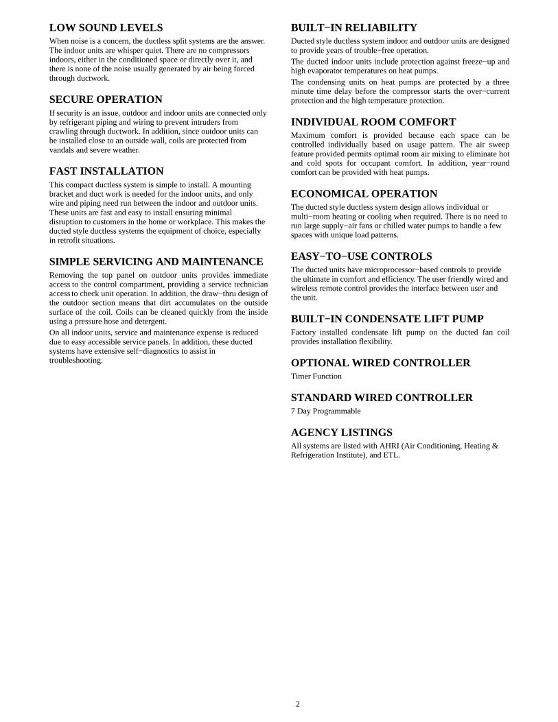
MODEL NUMBER NOMENCLATURE
BQ D
B = ALL SIZES
SYSTEM TYPEQ = HEAT PUMP
NOT USED
INDOOR UNIT
40 MB 309
40 = FAN COIL UNIT
MB = MODEL
VOLTAGE3 = 208/230-1-60
NOMINAL CAPACITY09 - 3/4 TON12 - 1 TON18 - 1-1/2 TONS 24 - 2 TONS 36 - 3 TONS48 - 4 TONS
INDOOR FAN COIL TYPE
D = DUCTED STYLE
- -
Use of the AHRI CertifiedTM Mark indicates amanufacturer’s participation in the program For verification of certification for individual products, go to www.ahridirectory.org.
4
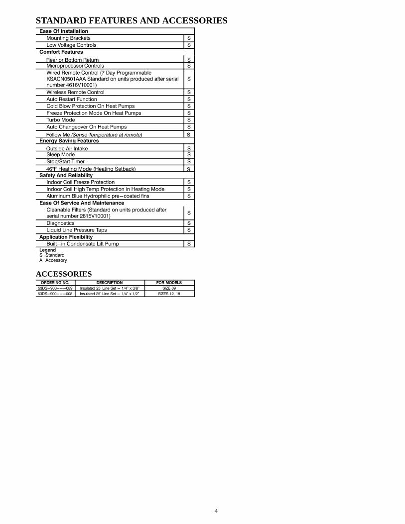
STANDARD FEATURES AND ACCESSORIESEase Of Installation
Mounting Brackets S
Low Voltage Controls S
Comfort Features
Rear or Bottom Return SMicroprocessor Controls S
Wired Remote Control (7 Day ProgrammableKSACN0501AAA Standard on units produced after serialnumber 4616V10001)
S
Wireless Remote Control S
Auto Restart Function S
Cold Blow Protection On Heat Pumps S
Freeze Protection Mode On Heat Pumps S
Turbo Mode S
Auto Changeover On Heat Pumps S
Follow Me (Sense Temperature at remote) SEnergy Saving Features
Outside Air Intake SSleep Mode S
Stop/Start Timer S
46°F Heating Mode (Heating Setback) SSafety And Reliability
Indoor Coil Freeze Protection S
Indoor Coil High Temp Protection in Heating Mode S
Aluminum Blue Hydrophilic pre-coated fins S
Ease Of Service And Maintenance
Cleanable Filters (Standard on units produced afterserial number 2815V10001)
S
Diagnostics S
Liquid Line Pressure Taps S
Application Flexibility
Built-in Condensate Lift Pump SLegendS StandardA Accessory
ACCESSORIESORDERING NO. DESCRIPTION FOR MODELS
53DS-900---089 Insulated 25’ Line Set - 1/4” x 3/8” SIZE 09
53DS-900---008 Insulated 25’ Line Set - 1/4“ x 1/2” SIZES 12, 18

5
DIMENSIONS − INDOOR
A
C
B
D
J
I
K
Air filter air inlet from rear side
air inlet from bottom side
FEGH
Electric control box
Air filter
L4-install hanger
Gas side
Liquid side
M
W1
W2
H1
H2
0.98(25) Drain connecting
pipe ( for pump )
Test mouth & Test cover
Outside Air Intake
Ø 0.98(25)
Drain pipe
Ø 0.98(25)
Drain pipe
Fig. 1 – Indoor Unit
OUTLINE DIMENSIONSAIR OUTLET
OPENING SIZEAIR RETURN
OPENING SIZEHANGAR
BRACKETSREFRIGERANT
PIPE LOCATIONS
OPERATINGWEIGHTlb. (kg)
Size A B C D E F G H I J K L M H1 H2 W1 W2
927.6(700)
8.2(210)
25(635)
22.4(570)
2.5(65)
19.4(493)
1.3(35)
4.6(119)
23.4(595)
7.8(200)
3.1(80)
29.1(740)
13.8(350)
4.7(120)
5.6(143)
3.7(95)
5.9(150)
39.9(18.1)
1227.6(700)
8.2(210)
25(635)
22.4(570)
2.5(65)
19.4(493)
1.3(35)
4.6(119)
23.4(595)
7.8(200)
3.1(80)
29.1(740)
13.8(350)
4.7(120)
5.6(143)
3.7(95)
5.9(150)
39.9(18.1)
1836.2(920)
8.2(210)
25(635)
22.4(570)
2.5(65)
28.07(713)
1.3(35)
4.6(119)
32.0(815)
7.8(200)
3.1(80)
37.8(960)
13.8(350)
4.7(120)
5.6(143)
3.7(95)
5.9(150)
50.7(23)
2436.2(920)
10.6(270)
25(635)
22.4(570)
2.5(65)
28.07(713)
1.3(35)
7.0(179)
32.0(815)
10.2(260)
0.7(20)
37.8(960)
13.8(350)
4.7(120)
5.6(143)
3.7(95)
5.9(150)
57.3(26)
3644.8
(1140)10.6(270)
30.5(775)
27.9(710)
2.5(65)
36.7(933)
1.3(35)
7.0(179)
40.7(1035)
10.2(260)
0.7(20)
46.5(1180)
19.3(490)
4.7(120)
5.6(143)
3.7(95)
5.9(150)
77.1(35)
4847.2
(1200)11.8(300)
34.1(865)
31.4(800)
3.1(80)
38.1(968)
1.5(40)
8.0(204)
43.0(1094)
11.3(288)
1.7(45)
48.8(1240)
19.7(500)
6.9(175)
7.8(198)
6.1(155)
8.3(210)
99.2(45)
6
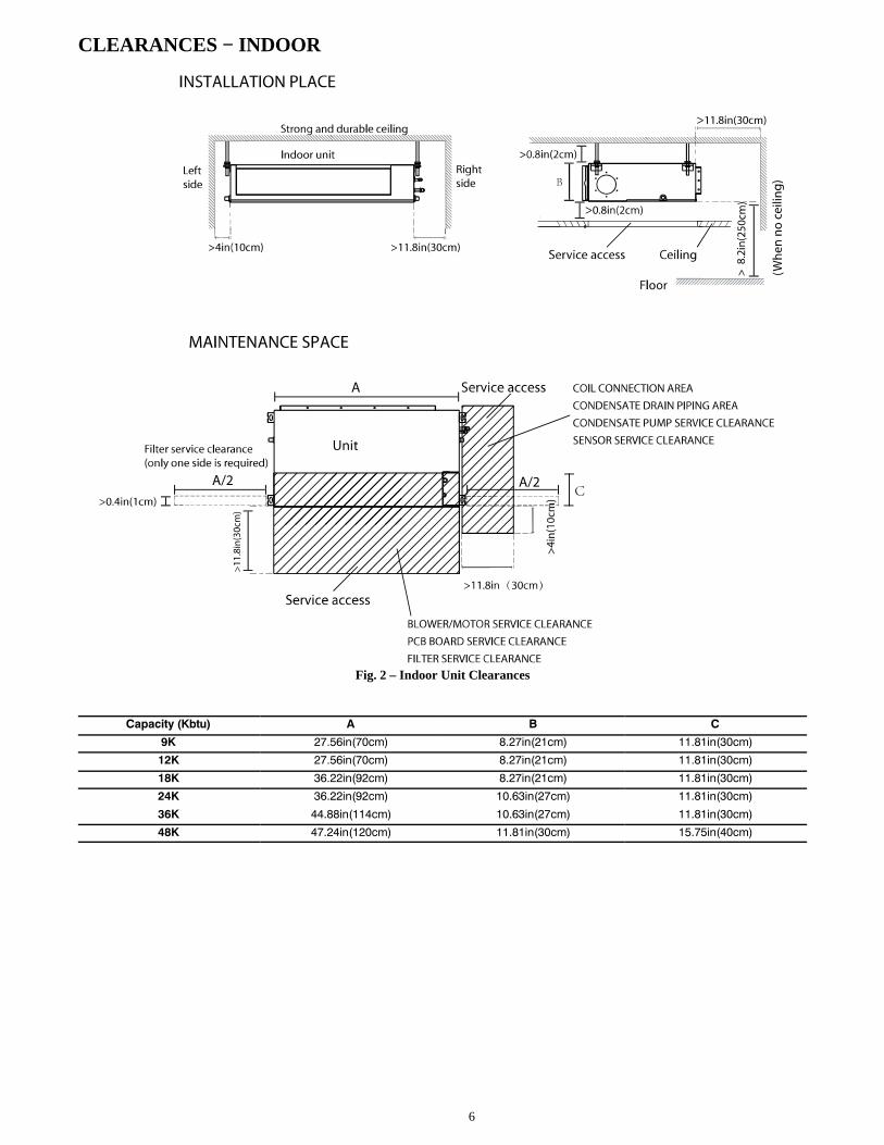
CLEARANCES − INDOOR
A
A/2 A/2
Fig. 2 – Indoor Unit Clearances
Capacity (Kbtu) A B C
9K 27.56in(70cm) 8.27in(21cm) 11.81in(30cm)
12K 27.56in(70cm) 8.27in(21cm) 11.81in(30cm)
18K 36.22in(92cm) 8.27in(21cm) 11.81in(30cm)
24K 36.22in(92cm) 10.63in(27cm) 11.81in(30cm)
36K 44.88in(114cm) 10.63in(27cm) 11.81in(30cm)
48K 47.24in(120cm) 11.81in(30cm) 15.75in(40cm)
7
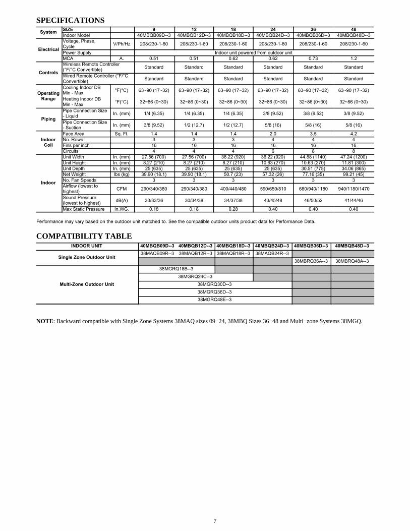
SPECIFICATIONSSystem
SIZE 9 12 18 24 36 48
Indoor Model 40MBQB09D--3 40MBQB12D--3 40MBQB18D--3 40MBQB24D--3 40MBQB36D--3 40MBQB48D--3
Electrical
Voltage, Phase,Cycle
V/Ph/Hz 208/230-1-60 208/230-1-60 208/230-1-60 208/230-1-60 208/230-1-60 208/230-1-60
Power Supply Indoor unit powered from outdoor unit
MCA A. 0.51 0.51 0.62 0.62 0.73 1.2
Controls
Wireless Remote Controller(°F/°C Convertible)
Standard Standard Standard Standard Standard Standard
Wired Remote Controller (°F/°CConvertible)
Standard Standard Standard Standard Standard Standard
OperatingRange
Cooling Indoor DBMin - Max
°F(°C) 63~90 (17~32) 63~90 (17~32) 63~90 (17~32) 63~90 (17~32) 63~90 (17~32) 63~90 (17~32)
Heating Indoor DBMin - Max
°F(°C) 32~86 (0~30) 32~86 (0~30) 32~86 (0~30) 32~86 (0~30) 32~86 (0~30) 32~86 (0~30)
Piping
Pipe Connection Size- Liquid
In. (mm) 1/4 (6.35) 1/4 (6.35) 1/4 (6.35) 3/8 (9.52) 3/8 (9.52) 3/8 (9.52)
Pipe Connection Size- Suction
In. (mm) 3/8 (9.52) 1/2 (12.7) 1/2 (12.7) 5/8 (16) 5/8 (16) 5/8 (16)
IndoorCoil
Face Area Sq. Ft. 1.4 1.4 1.4 2.0 3.5 4.2
No. Rows 3 3 3 4 4 4
Fins per inch 16 16 16 16 16 16
Circuits 4 4 4 6 8 8
Indoor
Unit Width In. (mm) 27.56 (700) 27.56 (700) 36.22 (920) 36.22 (920) 44.88 (1140) 47.24 (1200)
Unit Height In. (mm) 8.27 (210) 8.27 (210) 8.27 (210) 10.63 (270) 10.63 (270) 11.81 (300)
Unit Depth In. (mm) 25 (635) 25 (635) 25 (635) 25 (635) 30.51 (775) 34.06 (865)
Net Weight lbs (kg) 39.90 (18.1) 39.90 (18.1) 50.7 (23) 57.32 (26) 77.16 (35) 99.21 (45)
No. Fan Speeds 3 3 3 3 3 3
Airflow (lowest tohighest)
CFM 290/340/380 290/340/380 400/440/480 590/650/810 680/940/1180 940/1180/1470
Sound Pressure(lowest to highest)
dB(A) 30/33/36 30/34/38 34/37/38 43/45/48 46/50/52 41/44/46
Max Static Pressure In.WG. 0.18 0.18 0.28 0.40 0.40 0.40
Performance may vary based on the outdoor unit matched to. See the compatible outdoor units product data for Performance Data.
COMPATIBILITY TABLEINDOOR UNIT 40MBQB09D--3 40MBQB12D--3 40MBQB18D--3 40MBQB24D--3 40MBQB36D--3 40MBQB48D--3
Single Zone Outdoor Unit38MAQB09R--3 38MAQB12R--3 38MAQB18R--3 38MAQB24R--3
38MBRQ36A--3 38MBRQ48A--3
Multi-Zone Outdoor Unit
38MGRQ18B--3
38MGRQ24C--3
38MGRQ30D--3
38MGRQ36D--3
38MGRQ48E--3
NOTE: Backward compatible with Single Zone Systems 38MAQ sizes 09−24, 38MBQ Sizes 36−48 and Multi−zone Systems 38MGQ.
8
APPLICATION DATAUNIT SELECTIONSelect equipment to either match or that can handle slightly lessthan the anticipated peak load. This provides better humiditycontrol, fewer unit cycles, and less part−load operation.For units used in spaces with high sensible loads, base equipmentselection on unit sensible load, not on a total anticipated load.Adjust for anticipated room wet bulb temperature to avoidundersizing equipment.
UNIT MOUNTING (INDOOR)Refer to unit Installation Instructions for further details.Unit leveling − For reliable operation, units should be level in allplanes.Clearance − Provide adequate clearance for airflow as shown inFig. 3.Unit location − Select a location which provides the best aircirculation for the room.These units should be positioned as accessible as possible abovethe ceiling. The unit return and discharge should not be obstructedby furniture, curtains, or anything which may cause unit shortcycling or air recirculation. Duct the unit in the middle of theselected wall (if possible). Duct towards an outside wall, ifavailable, to make piping easier, and place the unit so it faces thenormal location of room occupants.
UNIT MOUNTING (OUTDOOR)Refer to unit Installation Instructions for further details.Do not install the indoor or outdoor units in a location with specialenvironmental conditions. For those applications, contact yourductless representative.
MOUNTINGRefer to unit’s Installation Instructions for further details.
SUPPORTAdequate support must be provided to support the weight of all fancoils. Refer to the Physical Data section for fan coil weights, andthe base unit dimensional drawings for the location of mountingbrackets.
SYSTEM OPERATING CONDITIONSOPERATING RANGE
Min / Max °F (°C)
Cooling Heating
Indoor DB 63 / 90 (17 / 32) 32 / 86 (0 / 30)
Indoor WB 59 / 84 (15 / 29)
NOTE: Reference the product Installation Instructions for moreinformation.
DRAIN CONNECTIONSInstall drains to meet local sanitation codes. The standard ductedfan coil unit condensate lift pump has a maximum lift of 29.5 in.(750mm).
WIRINGAll wires must be sized per NEC (National Electrical Code) orCEC (Canadian Electrical Code) and local codes. Use the ElectricalData table MCA (minimum circuit amps) and MOCP (maximumover current protection) to correctly size the wires and thedisconnect fuse or breakers respectively. Per the caution note, onlyStranded copper conductors with a 600 volt rating and doubleinsulated copper wire must be used.NOTE: The use of BX cable is not recommended.
Recommended Connection Method for Power andCommunication Wiring − Power andCommunication Wiring:The main power is supplied to the outdoor unit. The field supplied14/3 power/communication wiring from the outdoor unit to theindoor unit consists of four (4) wires and provides the power forthe indoor unit. Two wires are high voltage AC power, one iscommunication wiring and the other is a ground wire.
Recommended Connection Method for Power andCommunication Wiring (To minimizecommunication wiring interference)PowerWiring:The main power is supplied to the outdoor unit. The field suppliedpower wiring from the outdoor unit to the indoor unit consists ofthree (3) wires and provides the power for the indoor unit. Twowires are high voltage AC power and one is a ground wire. Tominimize voltage drop, the factory recommended wire size is 14/2stranded with a ground.
Communication Wiring:A separate shielded stranded copper conductor only, with aminimum 600 volt rating and double insulated copper wire, mustbe used as the communication wire from the outdoor unit to theindoor unit. Please use a separate shielded 16GA stranded controlwire.
CAUTION!
EQUIPMENT DAMAGE HAZARD
Failure to follow this caution may result in equipmentdamage or improper operation.
� Wires should be sized based on NEC and local codes.
� Use copper conductors only with a 600 volt rating anddouble insulated copper wire.
CAUTION!
EQUIPMENT DAMAGE HAZARD
Failure to follow this caution may result in equipmentdamage or improper operation.� Be sure to comply with local codes while running wire
from indoor unit to outdoor unit.� Every wire must be connected firmly. Loose wiring
may cause terminal to overheat or result in unitmalfunction. A fire hazard may also exist. Therefore,be sure all wiring is tightly connected.
� No wire should be allowed to touch refrigerant tubing,compressor or any moving parts.
� Disconnecting means must be provided and shall belocated within sight and readily accessible from the airconditioner.
� Connecting cable with conduit shall be routed throughhole in the conduit panel.
9
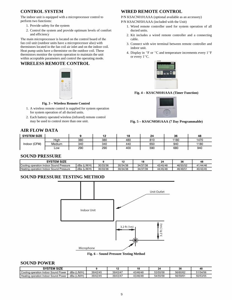
CONTROL SYSTEMThe indoor unit is equipped with a microprocessor control toperform two functions:
1. Provide safety for the system
2. Control the system and provide optimum levels of comfortand efficiency
The main microprocessor is located on the control board of thefan coil unit (outdoor units have a microprocessor also) withthermistors located in the fan coil air inlet and on the indoor coil.Heat pump units have a thermistor on the outdoor coil. Thesethermistors monitor the system operation to maintain the unitwithin acceptable parameters and control the operating mode.
WIRELESS REMOTE CONTROL
Fig. 3 – Wireless Remote Control
1. A wireless remote control is supplied for system operationfor system operation of all ducted units.
2. Each battery operated wireless (infrared) remote controlmay be used to control more than one unit.
WIRED REMOTE CONTROLP/N KSACN0101AAA (optional available as an accessory)P/N KSACN0501AAA (included with the Unit)
1. Wired remote controller used for system operation of allducted units.
2. Kit includes a wired remote controller and a connectingcable.
3. Connect with wire terminal between remote controller andindoor unit.
4. Display in �F or �C and temperature increments every 1�For every 1�C.
Fig. 4 – KSACN0101AAA (Timer Function)
Fig. 5 – KSACN0501AAA (7 Day Programmable)
AIR FLOW DATASYSTEM SIZE 9 12 18 24 36 48
Indoor (CFM)
High 380 380 480 810 1180 1470
Medium 340 340 440 650 940 1180
Low 290 290 400 590 680 940
SOUND PRESSURESYSTEM SIZE 9 12 18 24 36 48
Cooling operation Indoor Sound Pressure dBa (L/M/H) 30/33/36 30/34/38 34/37/38 43/45/48 46/50/52 41/44/46
Heating operation Indoor Sound Pressure dBa (L/M/H) 30/33/36 30/34/38 34/37/39 44/45/48 46/49/51 40/43/45
SOUND PRESSURE TESTING METHOD
3.2
ft (1
m)
3.2 ft (1m)
Indoor Unit
Unit Outlet
Microphone
x
Fig. 6 – Sound Pressure Testing Method
SOUND POWERSYSTEM SIZE 9 12 18 24 36 48
Cooling operation Indoor Sound Power dBa (L/M/H) 39/42/45 39/43/47 43/46/48 53/55/58 56/60/62 51/54/56
Heating operation Indoor Sound Power dBa (L/M/H) 39/42/45 39/43/47 43/46/48 54/55/58 56/59/61 50/53/55

10
ELECTRICAL DATA
UNIT SIZE INDOOR FANMAX FUSE
CB AMP
V-PH-HZ FLA HP W
Refer to outdoor unit installation instructions –Indoor unit powered by the outdoor unit
9
208-230/1/60
1.03 0.07 55
12 1.03 0.07 55
18 0.83 0.12 90
24 0.83 0.12 90
36 1.263 0.2 150
48 2.23 0.32 240
LEGEND
FLA - Full Load Amps
FAN AND MOTOR SPECIFICATIONSSYSTEM SIZE 9 12 18 24 36 48
IndoorFan
Material ABS ABS ABS ABS ABS ABS
Type LX-140*150*12-41J LX-140*150*12-41J LX-142*180*12-42J LX-188*190*12-40J LX-188*190*12-40J LX-188*190*12-40J
Diameter inch 140 140 142 188 188 188
Height inch 150 150 180 190 490 490
IndoorFan
Motor
Model WZDK55-38GS-W WZDK55-38GS-W WZDK90-38GS-W WZDK90-38GS-W WZDK150-38GS-W WZDK240-38GS-W
Type DC DC DC DC DC DC
Phase 3 3 3 3 3 3
FLA 1.03 1.03 0.83 0.83 1.263 2.23
Insulation class E E E E E E
SafeClass
IPX0 IPX0 IPX0 IPX0 IPX0 IPX0
Input W 118 118 143 143 167 276
Output W 55 55 90 90 150 240
Range ofCurrent
Amps 1.03±10% 1.03±10% 1.15±10% 1.15±10% 1.263±10% 2.23±10%
RatedCurrent
Amps 1.03 1.03 0.83 0.83 1.263 2.23
Rated HP HP 0.073 0.073 0.12 0.12 0.2 0.32
Speed rev/min 1100/950/800 1150/1000/900 1100/1050/880/820 1030/880/800 1120/1000/860 1040/950/830
RatedRPM
rev/min 1450 1450 1200 1200 1180 1200
Max.Input
W 118 118 143 143 167 276

11
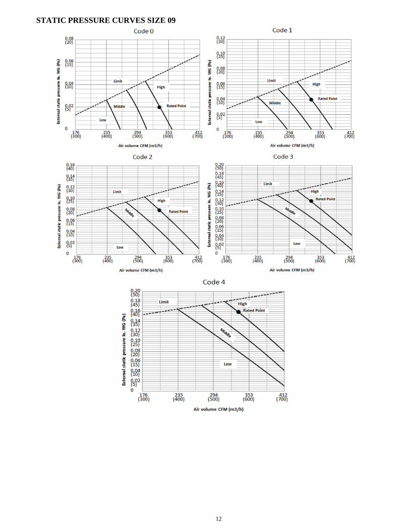
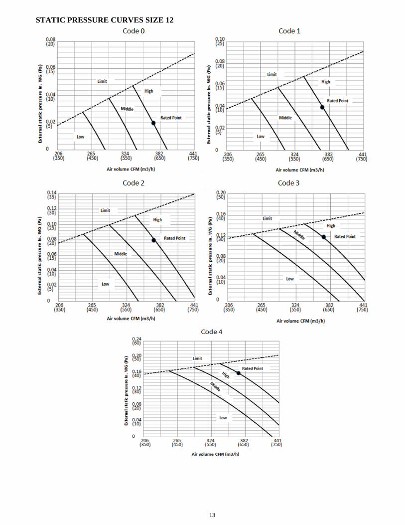
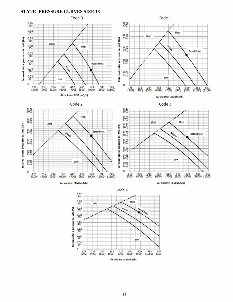
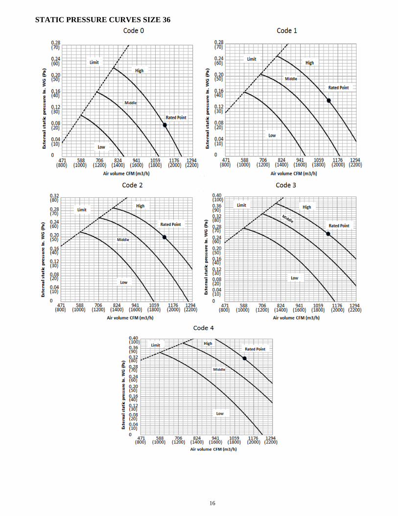
FAN PERFORMANCES AT VARYING STATIC PRESSURES (DUCTED UNITS)The static pressure of the indoor unit has been set in the factory according to the table below.
Static PressureRange In. WG (Pa)
Size 0 1 2 3 4
9 and 120.02(5)
0.04(10)
0.08(20)
0.12(30)
0.16(40)
0-0.18(0-45)
180.04(10)
0.10(25)
0.14(35)
0.18(45)
0.22(55)
0-0.28(0-70)
240.04(10)
0.10(25)
0.16(40)
0.22(55)
0.28(70)
0-0.40(0-100)
36 and 480.08(20)
0.14(35)
0.20(50)
0.26(65)
0.32(80)
0-0.40(0-100)
Factory Setting √
SYSTEM SIZE 9K 12K 18K 24K 36K 48K
HighCFM 335 370 520 820 1120 1470
CMH 570 629 884 1394 1904 2499
MediumCFM 290 320 430 620 940 1180
CMH 493 544 731 1054 1598 2006
LowCFM 240 260 360 520 680 940
CMH 408 442 612 884 1156 1598
12
STATIC PRESSURE CURVES SIZE 09
13
STATIC PRESSURE CURVES SIZE 12
14
STATIC PRESSURE CURVES SIZE 18

15
STATIC PRESSURE CURVES SIZE 24
16
STATIC PRESSURE CURVES SIZE 36

17
STATIC PRESSURE CURVES SIZE 48
18
WIRING DIAGRAMS
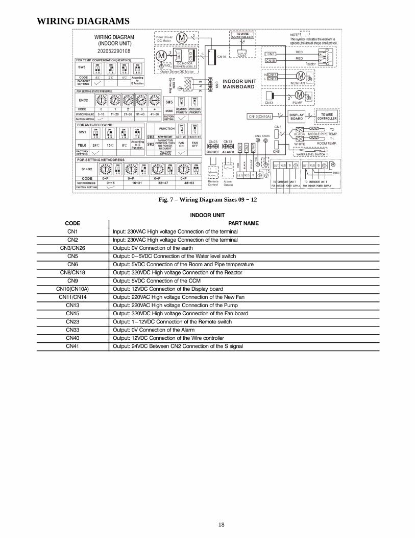
Fig. 7 – Wiring Diagram Sizes 09 − 12
INDOOR UNIT
CODE PART NAME
CN1 Input: 230VAC High voltage Connection of the terminal
CN2 Input: 230VAC High voltage Connection of the terminal
CN3/CN26 Output: 0V Connection of the earth
CN5 Output: 0-5VDC Connection of the Water level switch
CN6 Output: 5VDC Connection of the Room and Pipe temperature
CN8/CN18 Output: 320VDC High voltage Connection of the Reactor
CN9 Output: 5VDC Connection of the CCM
CN10(CN10A) Output: 12VDC Connection of the Display board
CN11/CN14 Output: 220VAC High voltage Connection of the New Fan
CN13 Output: 220VAC High voltage Connection of the Pump
CN15 Output: 320VDC High voltage Connection of the Fan board
CN23 Output: 1-12VDC Connection of the Remote switch
CN33 Output: 0V Connection of the Alarm
CN40 Output: 12VDC Connection of the Wire controller
CN41 Output: 24VDC Between CN2 Connection of the S signal

19
WIRING DIAGRAMS (CONT)
Fig. 8 – Wiring Diagram Size 18
INDOOR UNIT
CODE PART NAME
CN1 Input: 230VAC High voltage Connection of the terminal
CN2 Input: 230VAC High voltage Connection of the terminal
CN3/CN26 Output: 0V Connection of the earth
CN5 Output: 0-5VDC Connection of the Water level switch
CN6 Output: 5VDC Connection of the Room and Pipe temperature
CN8/CN18 Output: 320VDC High voltage Connection of the Reactor
CN9 Output: 5VDC Connection of the CCM
CN10(CN10A) Output: 12VDC Connection of the Display board
CN11/CN14 Output: 220VAC High voltage Connection of the New Fan
CN13 Output: 220VAC High voltage Connection of the Pump
CN15 Output: 320VDC High voltage Connection of the Fan board
CN23 Output: 1-12VDC Connection of the Remote switch
CN33 Output: 0V Connection of the Alarm
CN40 Output: 12VDC Connection of the Wire controller
CN41 Output: 24VDC Between CN2 Connection of the S signal
20
WIRING DIAGRAMS (CONT)
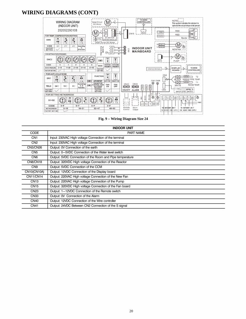
Fig. 9 – Wiring Diagram Size 24
INDOOR UNIT
CODE PART NAME
CN1 Input: 230VAC High voltage Connection of the terminal
CN2 Input: 230VAC High voltage Connection of the terminal
CN3/CN26 Output: 0V Connection of the earth
CN5 Output: 0-5VDC Connection of the Water level switch
CN6 Output: 5VDC Connection of the Room and Pipe temperature
CN8/CN18 Output: 320VDC High voltage Connection of the Reactor
CN9 Output: 5VDC Connection of the CCM
CN10(CN10A) Output: 12VDC Connection of the Display board
CN11/CN14 Output: 220VAC High voltage Connection of the New Fan
CN13 Output: 220VAC High voltage Connection of the Pump
CN15 Output: 320VDC High voltage Connection of the Fan board
CN23 Output: 1-12VDC Connection of the Remote switch
CN33 Output: 0V Connection of the Alarm
CN40 Output: 12VDC Connection of the Wire controller
CN41 Output: 24VDC Between CN2 Connection of the S signal

21
WIRING DIAGRAMS (CONT)
Fig. 10 – Wiring Diagram Size 36
INDOOR UNIT
CODE PART NAME
CN1 Input: 230VAC High voltage Connection of the terminal
CN2 Input: 230VAC High voltage Connection of the terminal
CN3 Output: 0V Connection of the earth
CN5 Output: 0-5VDC Connection of the Water level switch
CN6 Output: 5VDC Connection of the Room and Pipe temperature
CN7 Output: 5VDC Connection of the Outer Pipe temperature
CN9 Output: 5VDC Connection of the CCM and RS-485
CN10(CN10A) Output: 12VDC Connection of the Display board
CN13 Output: 220VAC High voltage Connection of the Pump
CN15 Output: 320VDC High voltage Connection of the Fan board
CN23 Output: 1-12VDC Connection of the Remote switch
CN33 Output: 0V Connection of the Alarm
CN40 Output: 12VDC Connection of the Wire controller
22
WIRING DIAGRAMS (CONT)
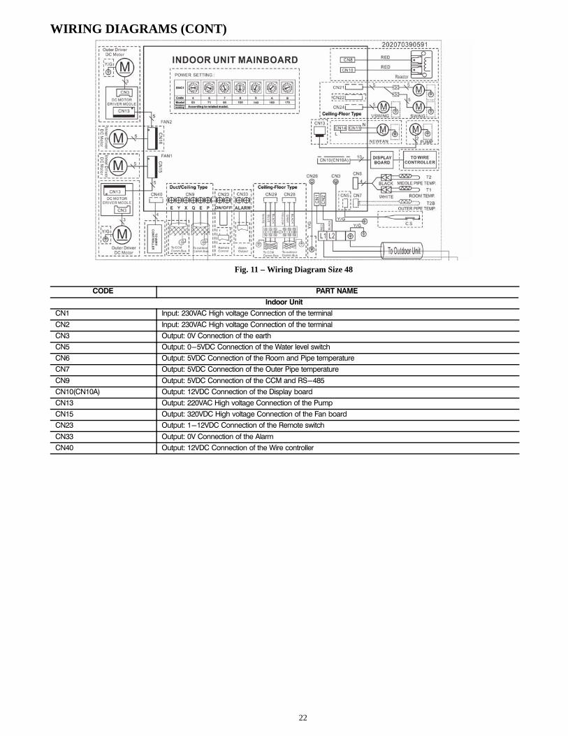
Fig. 11 – Wiring Diagram Size 48
CODE PART NAME
Indoor Unit
CN1 Input: 230VAC High voltage Connection of the terminal
CN2 Input: 230VAC High voltage Connection of the terminal
CN3 Output: 0V Connection of the earth
CN5 Output: 0-5VDC Connection of the Water level switch
CN6 Output: 5VDC Connection of the Room and Pipe temperature
CN7 Output: 5VDC Connection of the Outer Pipe temperature
CN9 Output: 5VDC Connection of the CCM and RS-485
CN10(CN10A) Output: 12VDC Connection of the Display board
CN13 Output: 220VAC High voltage Connection of the Pump
CN15 Output: 320VDC High voltage Connection of the Fan board
CN23 Output: 1-12VDC Connection of the Remote switch
CN33 Output: 0V Connection of the Alarm
CN40 Output: 12VDC Connection of the Wire controller
23
GUIDE SPECIFICATIONSINDOOR CEILING−MOUNTED DUCTED STYLE DUCTLESS UNITS
Size Range: 3/4 to 4 Ton Nominal Cooling and Heating CapacityModel Number: 40MB*D
PART 1 − GENERAL1.01 System DescriptionIndoor, ceiling−mounted, direct−expansion fan coils are matchedwith a heat pump outdoor unit.
1.02 Agency ListingsUnit is rated per AHRI Standards 210/240 and listed in the AHRIdirectory as a matched system.
1.03 Delivery, Storage, And HandlingUnits are stored and handled per unit the manufacturer’srecommendations.
1.04 Warranty (For Inclusion By SpecifyingEngineer)
PART 2 − PRODUCTS2.01 EquipmentA. General:Indoor, direct−expansion, ceiling−mounted fan coil. The unit iscomplete with cooling/heating coil, fan, fan motor, pipingconnectors, electrical controls, microprocessor control system, andintegral temperature sensing.B. Unit Cabinet:Unit cabinet is constructed of galvanized steel. The cabinet is fullyinsulated for improved thermal and acoustic performance.C. Fans:The fan is tangential direct−drive blower type with air intake at therear or bottom of the unit and discharge at the front.D. Coil:The coil is a copper tube with aluminum fins and galvanized steeltube sheets. The fins are bonded to the tubes by mechanicalexpansion and specially blue hydrophilic pre−coated for enhancedwet−ability. A drip pan under the coil has a factory installedcondensate pump and drain connection for hose attachment toremove condensate.E. Motors:The motors has an open drip−proof, permanently lubricated ballbearing with inherent overload protection. Fan motors are 3−speed.F. Controls:The controls consist of a microprocessor−based control systemwhich controls the space temperature, determines optimum fanspeed, and runs self diagnostics. The temperature control range is62�F to 86�F (17�C to 30�C) in increments of 1�F or 1�C, andhas a 46�F Heating Mode (Heating Setback). The wireless remotecontroller can act as the temperature sensing location for roomcomfort.
The unit has the following functions as a minimum:1. An automatic restart after power failure at the same
operating conditions as at failure.
2. A timer function to provide a minimum 24−hour timercycle for system Auto Start/Stop.
3. Temperature−sensing controls sense return air temperature.
4. Indoor coil freeze protection.5. Wireless infrared remote control to enter set points and
operating conditions.6. Dehumidification mode provides increased latent removal
capability by modulating system operation and set pointtemperature.
7. Fan−only operation to provide room air circulation when nocooling is required.
8. Diagnostics provide continuous checks of unit operationand warn of possible malfunctions. Error messages appearon the unit.
9. The fan speed control is user−selectable: high, medium,low, or microprocessor controlled automatic operationduring all operating modes.
10. Automatic heating−to−cooling changeover in heat pumpmode. The control includes deadband to prevent rapid modecycling between heating and cooling.
11. Indoor coil high temperature protection is provided to detectan excessive indoor discharge temperature when unit is inthe heat pump mode.
G. Electrical Requirements:The indoor fan motor operates on 208−230V. Power is suppliedfrom the outdoor unit.H. Operating Characteristics:The 40MB*D system has a minimum SEER (Seasonal EnergyEfficiency Ratio) and HSPF at AHRI conditions, as listed on thespecifications table.I. Refrigerant Lines:All units have refrigerant lines that can be oriented to connect fromthe side of the unit. Both refrigerant lines need to be insulated.

24
Copyright 2017 Carrier Corp. � 7310 W. Morris St. � Indianapolis, IN 46231 . Edition Date: 02/17
Manufacturer reserves the right to change, at any time, specifications and designs without notice and without obligations.
Catalog No: 40MBD-03PD
Replaces: 40MBD-02PD