Embed Size (px)
Citation preview

Copyright 2006 Carrier Corporation Form 35L,N-1PD
Dual duct variable air volume (VAV)terminal units provide:• 22-gage zinc coated steel• Optional 20-gage galvanized steel
casing for additional strength anddurability
• Casing and all optional liners meetUL-181 (Underwriters Laboratories)and NFPA-90A (National Fire Pro-tection Association) requirements
Features/BenefitsCarrier’s 35L,N terminal unitsoffer a compact design withdiverse control packages(pneumatic, analog, electricand direct digital controloptions).Flexible, high performance unitsThe 35L,N dual duct terminals aredesigned to maintain optimum temper-atures in the conditioned zone by vary-ing the air volume supplied by the hot and cold supply ducts while providing the proper discharge air temperature. Pressure independent pneumatic,analog electronic and direct digital electronic control sequences are avail-able for variable or constant volume applications.
35L35N
Dual Duct, Variable Air VolumeTerminal Units
50 to 7100 Nominal Cfm
ProductData
35L
35N

2
Application flexibilityThe 35L,N unit casings are construct-ed of 22 gage (20 gage optional) zinc coated steel. Units can be equipped without a liner or insulated (dual densi-ty, foil lined and cellular insulation op-tions available). Both casing and liner options meet NFPA-90A (National Fire
Protection Association) and UL-181 (Underwriters’ Laboratories) stan-dards. All units have round inlets, and rectangular discharge connections. All round inlets have a raised collar bead to ensure tight inlet duct connections.
The 35L (variable air volume only) unit features a compact design suited
for variable air volume applications where blending of hot and cold air is not required.
The 35N (variable or constant vol-ume) unit features an integral attenua-tor and hot/cold airstream blending chamber for precise discharge temper-ature control.
Table of contentsPage
Features/Benefits . . . . . . . . . . . . . . . . . . . . . . . . . . . . . . . . . . . . . . . . . . .1-3Model Number Nomenclature . . . . . . . . . . . . . . . . . . . . . . . . . . . . . . . . . . . 4ARI Capacity Ratings . . . . . . . . . . . . . . . . . . . . . . . . . . . . . . . . . . . . . . . . . 5Selection Procedure . . . . . . . . . . . . . . . . . . . . . . . . . . . . . . . . . . . . . . . . . . 5Physical Data . . . . . . . . . . . . . . . . . . . . . . . . . . . . . . . . . . . . . . . . . . . . . . . 6Options and Accessories . . . . . . . . . . . . . . . . . . . . . . . . . . . . . . . . . . . . . .6,7Dimensions . . . . . . . . . . . . . . . . . . . . . . . . . . . . . . . . . . . . . . . . . . . . . . .8,9Performance Data . . . . . . . . . . . . . . . . . . . . . . . . . . . . . . . . . . . . . . . .10-15Application Data . . . . . . . . . . . . . . . . . . . . . . . . . . . . . . . . . . . . . . . . . . . 16Guide Specifications . . . . . . . . . . . . . . . . . . . . . . . . . . . . . . . . . . . . . . .17,18
Features/Benefits (cont)

3
10000
8000
6000
4000
2000
1000
800
600
400
200
10080
60
40
20
100.01 .03 .05 0.1 0.3 0.5 1
710
522
362
232
2086
1449
1174927
3709
2840
7250
FLOW PROBE PRESSURE DIFFERENTIAL IN. WG
CF
M
CF
MA
TO
NE
INC
HS
IGN
AL
SIZE 4
SIZE 5SIZE 6SIZE 7SIZE 8SIZE 9SIZE 10SIZE 12SIZE 14SIZE 16
SIZE 22
522
927
1449
2086
2840
10
100
100
10000
0.01 0.10.02 0.04 0.06 0.2 0.3 0.4 0.6 0.8 1.01.19.74.6 5.8 6.8 8.20.0 3.41.2 1.8 2.3
CF
M
CF
M A
T O
NE
INC
H S
IGN
AL
PRESSURE DIFFERENTIAL IN. WGVOLTS (ANALOG CONTROLS)
SIZE 6 INLET
SIZE 8 INLETSIZE 10 INLETSIZE 12 INLETSIZE 14 INLETSIZE 16 INLET2000
4000
6000
8000
800
600
400
200
80
60
40
20
3665
927
3709
1449
2086
2840
10
100
1000
10000
0.01 0.1 1.0
CF
M A
T O
NE
INC
H S
IGN
AL
FLOWCONSTANT
0.02 0.04 0.06 0.2 0.3 0.4 0.6 0.8
0.0 3.4 111.2 1.8 2.3 4.6 5.8 6.8 8.2 9.7
PRESSURE DIFFERENTIAL IN. WG VOLTS (ANALOG CONTROLS)
CF
M
SIZE 14 AND 16 INLET
SIZE 12 INLET
SIZE 10 INLET
SIZE 8 INLET
SIZE 6 INLET
35L DUAL DUCT LINEAR PROBE CFM VS PRESSURE SIGNAL GRAPH35L DUAL DUCT INLET FLOW PROBE CHART
35N DUAL DUCT INLET FLOW PROBE CHART 35N DUAL DUCT OUTLET FLOW PROBE CHART
NOTE: Size 16 discharge is same as inlet.

4
Model number nomenclature35L MODEL NUMBER NOMENCLATURE
35N MODEL NUMBER NOMENCLATURE
LEGENDCCN — Carrier Control Network® ControlsPIC — Product Integrated Controls

5
35L ARI RATINGSDISCHARGE RADIATED
35N ARI RATINGSDISCHARGE RADIATED
LEGEND
*ARI — Air Conditioning and Refrigeration Institute.
Selection procedureRefer to the Carrier Electronic Selection Program for infor-mation to determine unit sizing for your needs. See thePerformance data tables in this document for airflow, pres-sure drop and sound information.
INLETSIZE
RATEDCFM
MIN.∆Ps
POWER LEVELS (dB) AT 1.5 IN. WG ∆Ps2 3 4 5 6 7
4 150 0.100 61 61 55 51 49 455 250 0.100 61 62 57 52 50 476 400 0.100 63 68 61 54 50 487 550 0.100 67 69 59 55 52 498 700 0.100 67 70 61 57 54 519 900 0.100 67 66 61 57 55 52
10 1100 0.100 67 66 61 58 56 5312 1600 0.100 68 68 64 60 57 5414 2100 0.100 69 68 64 61 58 5616 2800 0.100 70 68 64 62 59 57
INLETSIZE
RATEDCFM
MIN.∆Ps
POWER LEVELS (dB) AT 1.5 IN. WG ∆Ps2 3 4 5 6 7
4 150 0.100 58 50 43 38 35 315 250 0.100 59 53 45 38 35 326 400 0.100 60 58 50 39 36 337 550 0.100 60 58 50 41 36 348 700 0.100 60 59 50 42 37 359 900 0.100 60 56 50 42 39 35
10 1100 0.100 60 56 51 42 39 3512 1600 0.100 60 57 51 47 44 3614 2100 0.100 60 58 51 47 44 3616 2800 0.100 62 59 53 49 44 40
INLETSIZE
RATEDCFM
MIN.∆Ps
POWER LEVELS (dB) AT 1.5 IN. WG ∆Ps2 3 4 5 6 7
6 400 0.440 67 66 63 55 49 428 700 0.387 71 68 64 58 51 44
10 1100 0.541 63 65 62 56 52 4612 1600 0.467 68 64 63 57 52 4714 2100 0.531 68 67 64 59 54 4816 2800 0.462 72 70 66 60 56 52
INLETSIZE
RATEDCFM
MIN.∆Ps
POWER LEVELS (dB) AT 1.5 IN. WG ∆Ps2 3 4 5 6 7
6 400 0.440 63 61 53 46 43 408 700 0.387 65 61 55 51 50 50
10 1100 0.541 66 62 56 50 48 4612 1600 0.467 64 63 57 52 50 4714 2100 0.531 69 63 58 52 51 4816 2800 0.462 71 63 60 53 50 49
∆Ps — Difference in static pressure from the inlet to the dischargeMin ∆Ps — Minimum static pressure required to achieve rated airflow
35L units are tested and certified in accordance withARI Standard 880-98.
ARI* capacity ratings

6
35L UNIT WEIGHTS (lb)*
35N UNIT WEIGHTS (lb)*
DDC — Direct Digital Controls*Data based on the following:
1. Units are constructed with a 22 gage casing.2. Unit insulation is 1/2-in. thick 1.5 lb dual density insulation.
Options and accessoriesControl optionsThe 35L,N dual duct units are offered with a wide varietyof factory-mounted controls that regulate the volume of airdelivery from the unit and respond to cooling and heatingload requirements of the conditioned space. Stand-alonecontrols will fulfill the thermal requirements of a givencontrol space. These devices are available in both pneu-matic and electronic arrangements. Carrier PIC (ProductIntegrated Controls) is a communicating control that isintegrated with the building system. The PIC controls arecompatible with the CCN (Carrier Comfort Network®)system. A number of DDC (Direct Digital Controls) controlpackages by others are available for consignment mount-ing, as indicated.
Control offerings are:35(L,N)A: Analog Electronic35(L,N)C: PIC Direct Digital Electronic35(L,N)P: Pneumatic35(L,N)N: None or DDC by others
Each control approach offers a variety of operating func-tions; a control package number identifies combinations ofcontrol functions. The following listings contain the basicfunction arrangements for each control offering. Becauseof the variety of functions available, circuit diagrams, oper-ating sequences, and function descriptions are contained inseparate Application Data publications. Refer to the specif-ic control publication for details.
CCN control arrangementsThe CCN control packages must be used in combinationwith a thermostat. Thermostats are not included in theCCN package. 4160: Constant volume dual duct4170: 35N only, variable volume dual duct, constant mini-mum cooling (requires cold deck inlet and total flow probe)4175: 35N only, variable volume dual duct, cooling close-off during heating (requires hot deck inlet and total flowprobe)4180: Constant ventilation dual duct, Cooling only(requires cold deck inlet and total flow probe4190: Variable Air Volume (VAV) with Demand ControlVentilation (DCV) requires separate CO2 sensorCCN thermostats (ordered separately)Thermostat: 33ZCT55SPT: RT (room temperature) sensor,with override only.Thermostat: 33ZCT56SPT: RT (room temperature) sensor,with set point adjust and override.Thermostat: 33ZCT58SPT: Communicating room tem-perature sensor with LCD, set point adjust, fan control andoccupancy override.Thermostat: 33ZCT56CO2: RT (room temperature) andCO2
sensor, with set point adjust and override.Thermostat: 33ZCT55CO2: RT (room temperature) andCO2
sensor, with override only.
SIZE BASE UNIT WITH PNEUMATICCONTROLS
WITH DDC OR ANALOGCONTROLS
4,5,6 29 37 477,8 33 41 51
9,10 41 49 5912 51 59 6914 67 75 8516 75 83 9322 129 137 147
SIZE BASE UNIT WITH PNEUMATICCONTROLS
WITH DDC OR ANALOGCONTROLS
6 31 39 498 42 50 60
10 61 69 7912 80 88 9814 98 106 11616 111 119 129
Physical data

7
Analog electronic control arrangementControl package is pressure independent and includes astandard linear airflow sensor in both the hot and coldinlets for variable air volume control, 24 volt transformer,control enclosures, and a wall thermostat to match thecontrol type.2400 — Heating and cooling control, hot and cold inletairflow sensing (35L,N)2440 — Heating and cooling control, hot inlet and dis-charge airflow sensing (35N only)2470 — Heating and cooling control, cold inlet and dis-charge airflow sensing (35N only)
Direct digital electronic control arrangements (field supplied)Control packages are field supplied for factory mounting,unless otherwise noted. All DDC control arrangementsinclude a standard linear inlet flow sensor, transformer to24 volts and control enclosure.
Contact Carrier for details about mounting field-suppliedcontrols.
Pneumatic control arrangementAll control packages are pressure independent and includestandard linear airflow sensors in both the hot and cold in-lets for variable air volume control or an airflow sensor inone inlet and the unit discharge for constant volume con-trol arrangements.Variable air volume control (units 35L,N):Inlet air sensing1500 — Multi-function controller, DA-NC cold inlet, NChot inlet1501 — Multi-function controller, DA-NC cold inlet, NOhot inlet1502 — Multi-function controller, DA-NO cold inlet, NOhot inlet1503 — Multi-function controller, DA-NO cold inlet, NChot inlet1504 — Multi-function controller, RA-NC cold inlet, NChot inlet1505 — Multi-function controller, RA-NC cold inlet, NOhot inlet1506 — Multi-function controller, RA-NO cold inlet, NOhot inlet1507 — Multi-function controller, RA-NO cold inlet, NChot inletConstant volume control (35N):(Inlet/discharge air sensing)1508 — Multi-function controller, DA-NC cold inlet, NChot inlet
1509 — Multi-function controller, DA-NC cold inlet, NOhot inlet1510 — Multi-function controller, DA-NO cold inlet, NOhot inlet1511 — Multi-function controller, DA-NO cold inlet, NChot inlet1512 — Multi-function controller, RA-NC cold inlet, NChot inlet1513 — Multi-function controller, RA-NC cold inlet, NOhot inlet1514 — Multi-function controller, RA-NO cold inlet, NOhot inlet1515 — Multi-function controller, RA-NO cold inlet, NChot inlet1516 — Multi-function controller, DA-NC cold inlet, NChot inlet1517 — Multi-function controller, DA-NC cold inlet, NOhot inlet1518 — Multi-function controller, DA-NO cold inlet, NOhot inlet1519 — Multi-function controller, DA-NO cold inlet, NChot inlet1520 — Multi-function controller, RA-NC cold inlet, NChot inlet1521 — Multi-function controller, RA-NC cold inlet, NOhot inlet1522 — Multi-function controller, RA-NO cold inlet, NOhot inlet1523 — Multi-function controller, RA-NO cold inlet, NChot inletPneumatic control legend:DA — Direct acting thermostatRA — Reverse acting thermostatNO — Normally open damper positionNC — Normally closed damper positionMulti-function controller — Capable of providing DA-NO,DA-NC, RA-NC or RA-NO functions.
No Control0000: 35L,N box only D000: 35L,N box with control box onlyD001: 35L,N box with control box and transformer
Options and accessories (cont)

8
Dimensions — 35L base unit
INLET VIEW – SIZES 4-16 SIDE VIEW
**H18"
**H
**
C**
AIRFLOW
INLETD
W
CHARTED 'A' DIMENSION INCLUDESINLET ADAPTER PROVIDED
ON SIZES 4 & 5
**ALLOW AT LEAST 24" CLEARANCEFOR CONTROLS ON EITHER SIDE
OF ALL UNIT SIZES
A
A LOPTIONAL HANGER
BRACKET(6 PLCS)
OPTIONAL HANGER BRACKETS - (6 PLCS)
W 76 1/8”
INLET VIEW - SIZE 22 ONLY
35L BASE UNIT
NOTE: Dimensions are shown as inches (mm).
INLETSIZE(in.)
MAXIMUMRATED
AIRFLOWCFM (L/s)
A C D H L W
4 229 (108) 53/8 (137) 121/8 (308) 37/8 (98) 8 (203) 151/2 (394) 241/8 (613)5 358 (169) 53/8 (137) 121/8 (308) 47/8 (124) 8 (203) 151/2 (394) 241/8 (613)6 515 (243) 33/8 (86) 121/8 (308) 57/8 (149) 8 (203) 151/2 (394) 241/8 (613)7 701 (331) 33/8 (86) 121/8 (308) 67/8 (175) 10 (254) 151/2 (394) 241/8 (613)8 916 (432) 33/8 (86) 121/8 (308) 77/8 (200) 10 (254) 151/2 (394) 241/8 (613)9 1159 (547) 33/8 (86) 141/8 (359) 87/8 (225) 121/2 (318) 151/2 (394) 281/8 (714)
10 1431 (675) 33/8 (86) 141/8 (359) 97/8 (251) 121/2 (318) 151/2 (394) 281/8 (714)12 2060 (972) 33/8 (86) 161/8 (410) 117/8 (302) 15 (381) 151/2 (394) 321/8 (816)14 2804 (1323) 33/8 (86) 201/8 (511) 137/8 (352) 171/2 (445) 151/2 (394) 401/8 (1019)16 3662 (1728) 33/8 (86) 241/8 (613) 157/8 (403) 18 (457) 151/2 (394) 481/8 (1222)22 7000 (3304) 33/8 (86) 381/8 (968) 237/8 x 157/8 (606 x 403) 18 (457) 15 (381) 761/8 (1934)
9
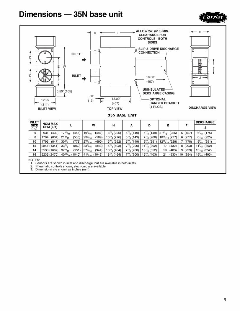
Dimensions — 35N base unit
J
H
J
A
.50”
INLET
(13)(457)
L
18.00”
18.00”
INLET
TOP VIEW DISCHARGE VIEW
(457)
SLIP & DRIVE DISCHARGECONNECTION
ALLOW 24” (610) MIN.CLEARANCE FOR
CONTROLS - BOTHSIDES
OPTIONALHANGER BRACKET(4 PLCS)
UNINSULATEDDISCHARGE CASING
W
D
12.25
E
F
D
6.50” (165)
(311)INLET VIEW
35N BASE UNIT
NOTES:1. Sensors are shown in inlet and discharge, but are available in both inlets.2. Pneumatic controls shown, electronic are available.3. Dimensions are shown as inches (mm).
INLETSIZE(in.)
NOM MAXCFM (L/s) L W H A D E F
DISCHARGE
J
6 931 (439) 1715/16 (456) 193/16 (487) 87/8 (225) 57/8 (149) 57/8 (149) 815/16 (226) 5 (127) 67/8 (175)8 1704 (804) 213/16 (538) 233/16 (589) 107/8 (276) 57/8 (149) 77/8 (200) 1015/16 (277) 6 (277) 87/8 (225)
10 1795 (847) 305/8 (778) 273/16 (690) 137/8 (352) 57/8 (149) 97/8 (251) 1215/16 (328) 7 (178) 97/8 (251)12 2841 (1341) 337/8 (860) 333/16 (843) 157/8 (403) 77/8 (200) 117/8 (302) 17 (432) 8 (203) 117/8 (302)14 3533 (1667) 377/16 (951) 373/16 (944) 181/4 (464) 77/8 (200) 137/8 (352) 19 (483) 9 (229) 137/8 (352)16 5235 (2470) 4015/16 (1040) 413/16 (1046) 181/4 (464) 77/8 (200) 157/8 (403) 21 (533) 10 (254) 157/8 (403)

10
35L NON-MIXING DUAL DUCTBASIC PRESSURE DATA
*CCN (Carrier Comfort Network®) controls permit a lower minimumflow.
NOTES:1. ∆Ps is the difference in static pressure across the assembly, with
the damper fully open.2. To obtain Total Pressure, add the Velocity Pressure for a
given CFM to the Static Pressure drop (∆Ps) of the desiredconfiguration.
INLETSIZE(in.)
CFM MINIMUM AIRFLOW(CFM)*
MINIMUM CCNAIRFLOW (CFM)
MINIMUM INLET STATIC PRESSURE(Unit Pressure Drop) (in. wg)
MINIMUM SYSTEM OPERATINGPRESSURE (in. wg)Velocity
PressureBasicUnit
∆ VPS ∆ PS
4(0.09)
50 40or0
23or0
0.02 0.00
0.03110 0.10 0.01170 0.23 0.02230 0.43 0.03
5(0.14)
75 63or0
36or0
0.02 0.00
0.08170 0.09 0.02265 0.23 0.04360 0.43 0.08
6(0.20)
100 90or0
52or0
0.02 0.01
0.17240 0.09 0.04380 0.22 0.09520 0.42 0.17
7(0.27)
150 123or0
71or0
0.02 0.01
0.17330 0.09 0.04525 0.23 0.09710 0.41 0.17
8(0.35)
200 160or0
93or0
0.02 0.01
0.18440 0.09 0.04675 0.21 0.09925 0.39 0.17
9(0.44)
250 203or0
117or0
0.02 0.01
0.31550 0.08 0.07875 0.21 0.17
1200 0.40 0.32
10(0.55)
300 251or0
145or0
0.02 0.01
0.17675 0.08 0.041075 0.20 0.101450 0.36 0.17
12(0.78)
450 361or0
208or0
0.02 0.01
0.171000 0.08 0.041550 0.19 0.092100 0.34 0.17
14(1.07)
600 491or0
284or0
0.01 0.01
0.181375 0.07 0.042125 0.17 0.102900 0.31 0.19
16(1.40)
800 642or0
371or0
0.01 0.01
0.181775 0.06 0.042725 0.14 0.093700 0.25 0.17
22(2.63)
1200 1211or0
699or0
0.00 0.00
0.173300 0.04 0.045200 0.09 0.097000 0.17 0.17
Performance data
11
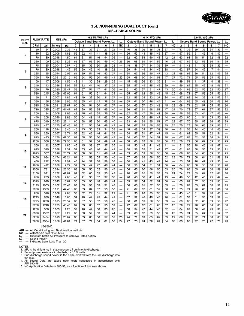
35L NON-MIXING DUAL DUCT (cont)DISCHARGE SOUND
LEGEND
NOTES:1. ∆Ps is the difference in static pressure from inlet to discharge.2. Sound power levels are in decibels, re 10-12 watts.3. End discharge sound power is the noise emitted from the unit discharge into
the duct.4. All Sound Data are based upon tests conducted in accordance with
ARI 880-98.5. NC Application Data from 885-98, as a function of flow rate shown.
INLETSIZE
FLOW RATE MIN ∆Ps0.5 IN. WG ∆Ps 1.0 IN. WG ∆Ps 2.0 IN. WG ∆Ps
Octave Band Sound Power, Lw Lp Octave Band Sound Power, Lw Lp Octave Band Sound Power, Lw Lp
CFM L/s in. wg pa 2 3 4 5 6 7 NC 2 3 4 5 6 7 NC 2 3 4 5 6 7 NC
4
50 24 0.002 0.39 45 37 32 31 27 22 — 46 38 36 35 31 27 — 47 39 39 39 34 33 —110 52 0.008 1.88 55 52 44 41 38 31 — 56 53 48 45 42 37 — 57 55 51 49 46 42 —170 80 0.018 4.50 61 61 51 46 44 36 — 62 62 54 50 48 42 21 63 63 58 54 52 48 22
230 109 0.033 8.23 65 67 55 50 49 40 26 66 68 59 54 52 46 28 67 69 62 58 56 51 29
5
75 35 0.004 0.87 45 35 33 30 28 23 — 48 38 37 34 33 29 — 51 42 41 38 38 35 —170 80 0.018 4.49 55 50 45 40 38 32 — 59 54 49 44 42 38 — 62 57 54 49 47 44 —
265 125 0.044 10.93 61 59 51 46 43 37 — 64 62 56 50 47 43 21 68 66 60 54 52 49 25360 170 0.081 20.16 65 64 56 50 46 41 23 68 68 60 54 51 47 27 72 71 65 59 55 52 31
6
100 47 0.006 1.56 42 41 30 28 29 25 — 45 46 36 33 35 31 — 49 51 41 37 40 38 —
240 113 0.036 8.95 52 52 44 40 37 32 — 55 57 49 45 43 39 — 59 62 55 49 48 46 21380 179 0.090 22.47 58 57 51 47 41 36 — 61 63 57 51 47 43 20 64 68 62 55 52 50 27520 245 0.169 42.05 61 61 56 51 44 39 — 65 67 62 55 49 45 25 68 72 67 59 55 52 31
7
150 71 0.007 1.85 48 49 32 30 31 27 — 52 55 38 33 37 34 — 57 62 44 36 43 42 21330 156 0.036 8.96 55 55 44 42 38 33 — 59 61 50 46 44 41 — 64 68 55 49 50 48 26525 248 0.091 22.67 60 58 51 50 42 37 — 64 65 57 53 49 45 23 68 71 62 57 55 52 30
710 335 0.167 41.47 62 60 55 55 45 40 — 66 67 61 58 51 47 24 70 73 67 61 57 55 32
8
200 94 0.008 2.03 49 46 41 35 36 31 — 52 52 47 39 41 38 — 56 58 53 44 47 45 —440 208 0.040 9.83 56 54 49 45 42 37 — 60 60 55 49 47 44 — 63 65 61 54 53 50 24
675 319 0.093 23.14 60 58 53 50 45 40 — 63 64 59 55 51 47 22 67 70 65 59 56 53 29925 437 0.175 43.45 63 61 56 54 48 42 — 66 67 62 59 53 49 25 70 73 68 63 59 56 31
9
250 118 0.014 3.45 45 43 35 33 34 33 — 48 48 39 37 39 40 — 51 53 44 40 44 46 —
550 260 0.067 16.71 55 52 46 44 41 39 — 58 57 51 47 47 45 — 61 62 55 51 52 51 —875 413 0.170 42.30 61 58 53 50 46 42 — 64 63 57 54 51 48 — 67 67 62 58 56 54 25
1200 566 0.320 79.56 65 61 57 54 49 44 — 68 66 62 58 54 50 23 70 71 66 62 59 56 29
10
300 142 0.007 1.85 45 45 38 37 37 35 — 48 50 43 41 43 41 — 51 55 48 46 48 47 —675 319 0.038 9.37 54 53 48 46 44 41 — 58 58 53 51 49 47 — 61 63 58 55 55 53 21
1075 507 0.096 23.77 60 58 54 51 48 44 — 63 63 59 56 53 50 — 66 68 64 60 59 56 25
1450 684 0.174 43.24 64 61 58 55 50 46 — 67 66 63 59 56 52 23 70 71 68 64 61 59 29
12
450 212 0.008 1.97 46 44 37 38 39 38 — 50 49 41 43 44 44 — 53 54 46 47 49 50 —1000 472 0.039 9.72 57 53 49 47 46 44 — 60 58 54 51 51 50 — 64 63 58 56 56 56 20
1550 731 0.094 23.35 63 58 56 52 50 47 — 66 63 60 56 55 53 20 70 68 65 61 60 59 262100 991 0.172 42.87 67 62 60 55 53 49 — 70 67 65 59 58 55 24 74 72 69 64 62 61 30
14
600 283 0.008 2.03 43 41 35 37 37 38 — 46 46 38 41 41 43 — 49 50 42 45 45 49 —
1375 649 0.043 10.67 56 53 50 48 46 44 — 59 57 54 52 51 50 — 63 61 57 56 55 55 —2125 1003 0.102 25.48 63 59 58 53 51 48 — 66 63 61 57 55 53 — 70 67 65 61 60 59 252900 1369 0.191 47.45 68 63 64 57 55 50 — 71 67 67 61 59 56 25 75 71 70 65 63 61 30
16
800 378 0.008 2.03 38 32 24 31 32 29 — 41 36 28 35 36 35 — 45 40 31 39 40 40 —1775 838 0.040 10.00 54 48 44 45 44 41 — 57 52 48 49 48 46 — 61 57 51 53 53 52 —2725 1286 0.095 23.57 63 57 55 52 50 47 — 66 61 59 56 55 53 — 69 65 62 60 59 58 22
3700 1746 0.175 43.45 69 63 63 57 55 52 — 72 67 67 61 60 57 25 76 72 70 65 64 63 30
22
1200 566 0.005 1.23 52 46 44 38 35 26 — 58 54 47 44 40 32 — 64 62 50 49 45 38 —3300 1557 0.037 9.29 63 58 59 53 50 44 — 69 66 62 59 55 50 23 75 74 65 64 61 57 32
5200 2454 0.093 23.07 68 63 66 60 57 52 20 74 71 69 65 62 59 29 80 79 72 71 68 65 387000 3304 0.168 41.81 71 67 71 64 61 58 24 77 75 74 70 67 64 33 83 83 77 75 72 70 43
ARI — Air Conditioning and Refrigeration InstituteNC — ARI 885-98 Test ConditionsLp — Minimum Static Air Pressure to Achieve Rated AirflowLw — Sound Power— — Indicates Level Less Than 20

12
35L NON-MIXING DUAL DUCT (cont)RADIATED SOUND POWER
LEGEND
NOTES:1. ∆Ps is the difference in static pressure from inlet to discharge.2. Sound power levels are in decibels, re 10-12 watts.3. Radiated sound power is the noise transmitted through the casing walls.4. All Sound Data are based upon tests conducted in accordance with
ARI 880-98.5. NC Application Data from 885-98, mineral tile ceiling.
INLETSIZE
FLOW RATE MIN ∆Ps0.5 IN. WG ∆Ps 1.0 IN. WG ∆Ps 2.0 IN. WG ∆Ps
Octave Band Sound Power, Lw Lp Octave Band Sound Power, Lw Lp Octave Band Sound Power, Lw Lp
CFM L/s in. wg pa 2 3 4 5 6 7 NC 2 3 4 5 6 7 NC 2 3 4 5 6 7 NC
4
50 24 0.002 0.39 36 27 22 21 16 7 — 37 28 25 24 18 12 — 38 30 28 26 20 17 —
110 52 0.008 1.88 49 41 32 32 29 21 — 50 42 36 34 31 25 — 51 44 39 36 33 30 —170 80 0.018 4.50 56 49 38 38 36 28 — 57 50 42 40 38 33 — 58 52 45 42 40 37 —230 109 0.033 8.23 61 54 43 42 41 33 24 62 56 46 44 43 38 25 63 57 50 46 45 42 26
5
75 35 0.004 0.87 39 22 17 14 9 5 — 45 27 22 17 13 11 — 50 32 27 20 17 18 —170 80 0.018 4.49 48 37 29 27 23 16 — 53 42 34 31 26 22 — 59 47 40 34 30 29 20265 125 0.044 10.93 53 45 36 35 30 22 — 58 50 41 38 34 28 — 63 55 46 41 38 35 26
360 170 0.081 20.16 56 50 41 40 35 26 — 61 55 46 43 39 32 24 67 60 51 46 43 39 31
6
100 47 0.006 1.56 41 32 22 20 16 10 — 44 37 26 23 20 15 — 48 41 30 27 24 21 —240 113 0.036 8.95 50 43 35 33 29 22 — 53 48 39 36 32 28 — 56 52 44 39 36 33 20
380 179 0.090 22.47 55 49 43 39 35 28 — 58 53 47 42 39 34 22 61 58 51 45 43 40 27520 245 0.169 42.05 58 53 48 44 40 33 22 61 57 52 47 43 39 26 64 62 56 50 47 44 32
7
150 71 0.007 1.85 38 40 24 18 13 6 — 42 45 30 22 17 12 — 46 51 36 26 21 17 —330 156 0.036 8.96 48 45 35 29 24 17 — 51 51 41 33 28 23 — 55 56 47 37 32 28 25525 248 0.091 22.67 53 48 41 36 31 23 — 57 54 47 40 35 29 22 61 59 53 44 39 35 29
710 335 0.167 41.47 57 50 45 40 36 27 — 61 56 51 44 40 33 25 64 61 57 48 44 39 32
8
200 94 0.008 2.03 42 36 29 24 22 14 — 45 41 36 29 27 21 — 49 47 43 34 32 28 —440 208 0.040 9.83 50 43 37 33 30 22 — 53 49 44 38 35 29 — 56 54 51 43 40 36 25
675 319 0.093 23.14 54 47 41 38 34 27 — 57 52 48 42 39 34 22 60 58 55 47 44 40 30925 437 0.175 43.45 57 49 44 41 37 30 — 60 55 51 46 42 37 26 63 61 58 51 47 44 33
9
250 118 0.014 3.45 39 33 22 23 20 16 — 42 39 27 27 26 25 — 46 45 31 31 31 33 —
550 260 0.067 16.71 48 39 34 32 28 21 — 52 45 39 36 33 29 — 55 51 43 40 39 38 —875 413 0.170 42.30 54 43 41 37 32 23 — 57 49 46 41 38 32 — 61 55 50 45 43 40 24
1200 566 0.320 79.56 58 45 46 41 35 25 — 61 51 50 45 41 33 25 64 57 55 49 46 42 29
10
300 142 0.007 1.85 32 30 20 16 10 –1 — 37 36 23 21 18 11 — 43 43 27 26 27 22 —675 319 0.038 9.37 42 38 36 29 21 9 — 48 44 39 34 29 21 — 54 50 43 38 37 32 —
1075 507 0.096 23.77 48 42 45 36 27 15 — 54 48 48 41 35 26 22 60 54 52 45 43 38 26
1450 684 0.174 43.24 52 44 51 40 30 18 25 58 51 54 45 39 30 29 64 57 58 50 47 42 33
12
450 212 0.008 1.97 38 42 29 24 21 15 — 43 46 33 28 26 20 — 47 51 38 32 31 26 —1000 472 0.039 9.72 47 46 39 35 32 24 — 51 50 43 39 36 30 — 56 55 48 43 41 35 23
1550 731 0.094 23.35 52 48 44 40 37 29 — 56 52 49 44 42 35 23 60 57 54 48 47 40 282100 991 0.172 42.87 55 49 48 44 41 32 22 59 54 53 48 46 38 27 64 59 57 52 51 44 32
14
600 283 0.008 2.03 34 33 23 25 24 22 — 39 39 26 29 28 27 — 43 44 30 32 32 31 —
1375 649 0.043 10.67 45 41 37 35 34 30 — 49 47 40 38 37 35 — 54 52 43 42 41 39 202125 1003 0.102 25.48 50 45 44 40 39 34 — 55 51 48 43 43 39 22 59 56 51 47 46 43 252900 1369 0.191 47.45 54 48 50 43 42 37 24 59 54 53 47 46 42 27 63 59 56 50 50 46 31
16
800 378 0.008 2.03 38 35 30 29 25 19 — 42 41 35 34 32 27 — 47 46 40 39 40 35 —1775 838 0.040 10.00 48 43 40 37 32 25 — 52 49 45 42 39 33 — 57 54 50 47 46 41 242725 1286 0.095 23.57 53 47 45 41 36 29 — 58 53 50 47 43 37 25 63 59 55 52 50 45 30
3700 1746 0.175 43.45 57 50 49 45 38 31 23 62 56 54 50 46 39 29 66 62 59 55 53 48 34
22
1200 566 0.005 1.23 46 49 39 39 40 39 — 50 52 43 41 42 41 — 53 54 47 43 44 43 233300 1557 0.037 9.29 55 55 50 48 49 48 24 59 58 54 50 51 50 28 63 61 58 52 53 52 32
5200 2454 0.093 23.07 60 58 55 51 53 52 30 64 61 59 54 55 54 34 68 64 62 56 57 56 387000 3304 0.168 41.81 63 60 58 54 56 55 33 67 63 62 56 58 57 37 70 66 66 58 60 59 41
ARI — Air Conditioning and Refrigeration InstituteNC — ARI 885-98 Test ConditionsLp — Minimum Static Air Pressure to Achieve Rated AirflowLw — Sound Power— — Indicates Level Less Than 20
Performance data (cont)
13
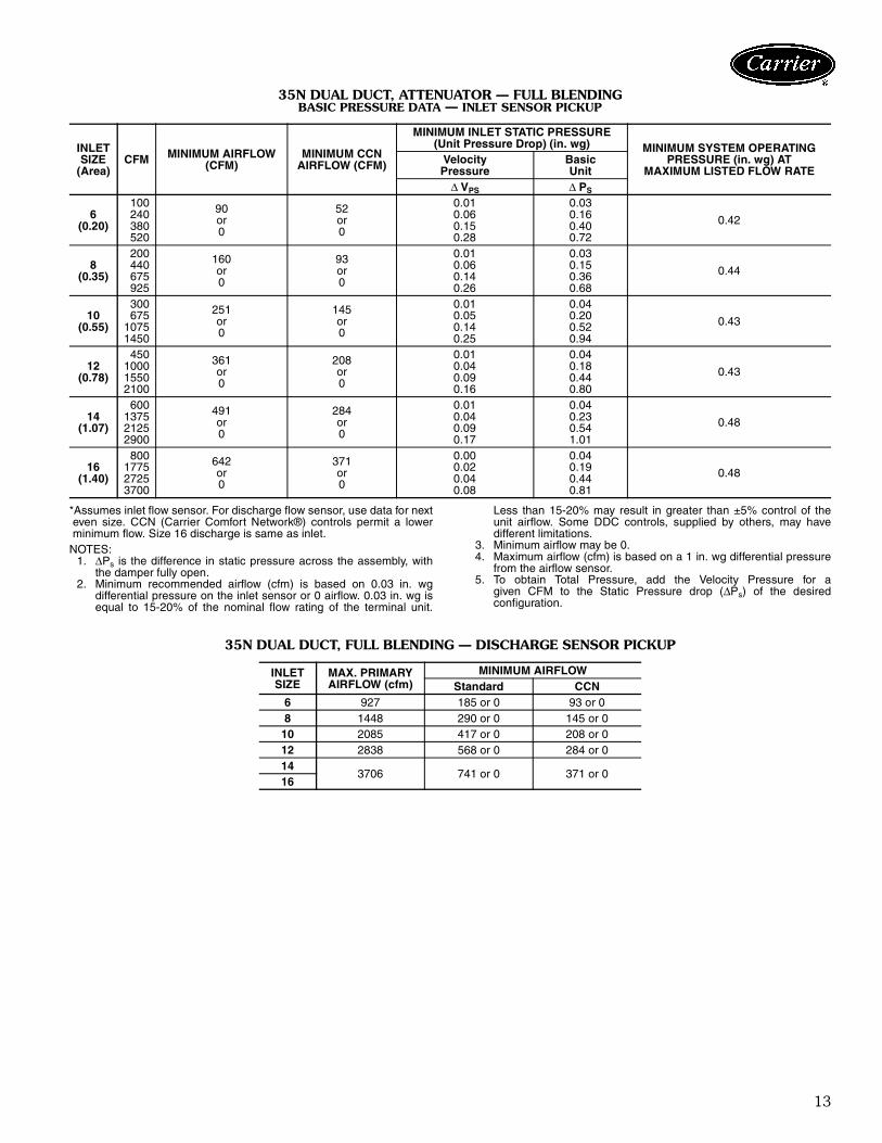
35N DUAL DUCT, ATTENUATOR — FULL BLENDINGBASIC PRESSURE DATA — INLET SENSOR PICKUP
*Assumes inlet flow sensor. For discharge flow sensor, use data for nexteven size. CCN (Carrier Comfort Network®) controls permit a lowerminimum flow. Size 16 discharge is same as inlet.
NOTES:1. ∆Ps is the difference in static pressure across the assembly, with
the damper fully open.2. Minimum recommended airflow (cfm) is based on 0.03 in. wg
differential pressure on the inlet sensor or 0 airflow. 0.03 in. wg isequal to 15-20% of the nominal flow rating of the terminal unit.
Less than 15-20% may result in greater than ±5% control of theunit airflow. Some DDC controls, supplied by others, may havedifferent limitations.
3. Minimum airflow may be 0.4. Maximum airflow (cfm) is based on a 1 in. wg differential pressure
from the airflow sensor.5. To obtain Total Pressure, add the Velocity Pressure for a
given CFM to the Static Pressure drop (∆Ps) of the desiredconfiguration.
35N DUAL DUCT, FULL BLENDING — DISCHARGE SENSOR PICKUP
INLETSIZE
(Area)CFM MINIMUM AIRFLOW
(CFM)MINIMUM CCN
AIRFLOW (CFM)
MINIMUM INLET STATIC PRESSURE(Unit Pressure Drop) (in. wg) MINIMUM SYSTEM OPERATING
PRESSURE (in. wg) ATMAXIMUM LISTED FLOW RATE
VelocityPressure
BasicUnit
∆ VPS ∆ PS
6(0.20)
100 90or0
52or0
0.01 0.03
0.42240 0.06 0.16380 0.15 0.40520 0.28 0.72
8(0.35)
200 160or0
93or0
0.01 0.03
0.44440 0.06 0.15675 0.14 0.36925 0.26 0.68
10(0.55)
300 251or0
145or0
0.01 0.04
0.43675 0.05 0.201075 0.14 0.521450 0.25 0.94
12(0.78)
450 361or0
208or0
0.01 0.04
0.431000 0.04 0.181550 0.09 0.442100 0.16 0.80
14(1.07)
600 491or0
284or0
0.01 0.04
0.481375 0.04 0.232125 0.09 0.542900 0.17 1.01
16(1.40)
800 642or0
371or0
0.00 0.04
0.481775 0.02 0.192725 0.04 0.443700 0.08 0.81
INLETSIZE
MAX. PRIMARYAIRFLOW (cfm)
MINIMUM AIRFLOWStandard CCN
6 927 185 or 0 93 or 08 1448 290 or 0 145 or 0
10 2085 417 or 0 208 or 012 2838 568 or 0 284 or 014
3706 741 or 0 371 or 016

14
35N DUAL DUCT, FULL BLENDING (cont)DISCHARGE SOUND
LEGEND
NOTES:1. ∆Ps is the difference in static pressure from inlet to discharge.2. Sound power levels are in decibels, re 10-12 watts.3. End discharge sound power is the noise emitted from the unit discharge into
the duct.4. All Sound Data are based upon tests conducted in accordance with
ARI 880-98.5. NC Application Data from ARI 885-98, at airflow shown.
INLETSIZE
FLOW RATE MIN ∆Ps0.5 IN. WG ∆Ps 1.0 IN. WG ∆Ps 2.0 IN. WG ∆Ps
Octave Band Sound Power, Lw Lp Octave Band Sound Power, Lw Lp Octave Band Sound Power, Lw Lp
CFM L/s in. wg pa 2 3 4 5 6 7 NC 2 3 4 5 6 7 NC 2 3 4 5 6 7 NC
6
100 47 0.028 6.8 44 44 40 31 27 21 — 49 50 48 38 33 28 — 54 57 55 46 40 36 —
240 113 0.158 39.4 53 51 47 39 34 27 — 59 58 54 46 41 34 — 64 64 62 54 47 42 24380 179 0.398 98.9 59 55 50 44 38 30 — 64 62 58 51 44 38 — 69 68 65 58 51 45 27520 245 0.744 185.1 * * * * * * — 67 65 60 54 47 40 23 72 71 68 61 54 47 30
8
200 94 0.032 7.9 49 48 43 38 32 23 — 55 55 51 45 39 31 — 61 63 59 52 46 39 22440 208 0.153 38.0 57 53 49 43 37 28 — 63 60 56 50 44 37 — 69 68 64 58 51 45 26675 319 0.360 89.5 62 56 52 46 40 31 — 67 63 59 53 47 39 21 73 70 67 60 54 48 30
925 437 0.676 168.1 * * * * * * — 71 65 62 55 49 42 22 76 72 69 63 56 50 31
10
300 142 0.040 10.0 41 44 41 37 32 23 — 47 52 48 42 36 29 — 54 59 55 48 41 35 —675 319 0.204 50.7 48 50 47 44 39 31 — 55 57 54 49 44 37 — 61 65 61 55 49 44 23
1075 507 0.517 128.6 * * * * * * — 59 60 57 53 49 42 — 65 68 64 59 53 49 251450 684 0.941 234.1 * * * * * * — 62 62 60 56 52 46 — 68 70 67 61 56 52 28
12
450 212 0.037 9.2 53 48 46 40 35 28 — 59 55 52 45 39 34 — 65 61 58 50 44 40 —1000 472 0.182 45.4 57 51 51 46 41 33 — 63 58 57 51 45 40 — 68 65 63 56 50 46 221550 731 0.438 109.0 59 53 53 49 44 36 — 64 60 59 54 49 43 — 70 67 65 59 54 49 24
2100 991 0.804 200.1 * * * * * * — 66 61 61 56 51 45 — 72 68 67 61 56 51 26
14
600 283 0.043 10.8 49 47 46 41 35 27 — 55 55 52 46 40 34 — 62 62 58 51 45 41 211375 649 0.228 56.6 54 52 51 47 42 34 — 61 60 58 52 47 41 — 68 67 64 58 52 48 25
2125 1003 0.544 135.3 * * * * * * — 64 62 61 56 51 44 — 71 70 67 61 56 51 282900 1369 1.013 252.0 * * * * * * — 66 64 63 58 54 47 21 73 72 69 63 59 54 30
16
800 378 0.038 9.4 58 55 53 47 41 38 — 61 58 55 48 42 39 — 64 61 57 50 44 41 —
1775 838 0.186 46.2 64 62 59 54 49 45 — 67 65 61 55 51 46 22 70 67 64 57 52 48 252725 1286 0.437 108.8 67 65 63 58 54 49 23 70 68 65 59 55 50 26 73 71 67 61 57 52 293700 1746 0.806 200.7 * * * * * * — 72 71 67 62 58 53 29 75 73 70 64 60 55 32
ARI — Air Conditioning and Refrigeration InstituteNC — ARI 885-98 Test ConditionsLp — Minimum Static Air Pressure to Achieve Rated AirflowLw — Sound Power* — Indicates Data Point Exceeds Minimum Pressure— — Indicates Level Less Than 20
Performance data (cont)

15
35N DUAL DUCT, FULL BLENDING (cont)RADIATED SOUND POWER
LEGEND
NOTES:1. ∆Ps is the difference in static pressure from inlet to discharge.2. Sound power levels are in decibels, re 10-12 watts.3. Radiated sound power is the noise transmitted through the casing walls.4. All Sound Data are based upon tests conducted in accordance with
ARI 880-98.5. NC Application Data from ARI 885-98, mineral tile ceiling.
INLETSIZE
FLOW RATE MIN ∆Ps0.5 IN. WG ∆Ps 1.0 IN. WG ∆Ps 2.0 IN. WG ∆Ps
Octave Band Sound Power, Lw Lp Octave Band Sound Power, Lw Lp Octave Band Sound Power, Lw Lp
CFM L/s in. wg pa 2 3 4 5 6 7 NC 2 3 4 5 6 7 NC 2 3 4 5 6 7 NC
6
100 47 0.028 6.8 40 37 29 24 25 23 — 45 44 37 30 30 31 — 51 52 45 36 35 38 —240 113 0.158 39.4 49 45 36 32 31 27 — 55 52 44 38 36 34 20 60 60 52 44 41 41 29380 179 0.398 98.9 54 49 39 37 35 29 — 60 56 48 42 40 36 25 65 64 56 48 45 43 34
520 245 0.744 185.1 * * * * * * — 63 59 50 45 42 37 28 69 67 58 51 47 44 37
8
200 94 0.032 7.9 51 50 41 39 41 41 — 51 49 41 39 40 40 — 50 48 40 38 40 39 —440 208 0.153 38.0 61 58 50 47 47 47 27 60 57 50 46 47 46 26 59 56 49 46 46 46 25
675 319 0.360 89.5 66 62 55 51 51 50 32 65 61 55 51 50 50 31 64 61 54 50 50 49 30925 437 0.676 168.1 * * * * * * — 69 65 58 54 53 52 35 68 64 57 53 53 52 34
10
300 142 0.040 10.0 42 41 33 30 29 27 — 50 48 39 34 34 33 — 57 56 44 39 38 39 25
675 319 0.204 50.7 50 47 42 39 37 33 — 57 54 48 43 41 39 23 64 62 53 47 46 45 321075 507 0.517 128.6 * * * * * * — 61 58 53 48 46 42 27 68 65 58 52 50 48 361450 684 0.941 234.1 * * * * * * — 64 60 56 51 49 44 31 71 68 62 55 53 50 39
12
450 212 0.037 9.2 42 43 35 32 29 26 — 50 51 41 37 34 33 — 57 58 46 41 38 40 281000 472 0.182 45.4 49 48 44 40 38 33 — 56 56 49 45 42 39 24 63 64 55 49 47 46 341550 731 0.438 109.0 52 51 49 44 42 36 23 60 59 54 49 47 43 29 67 66 59 54 51 50 37
2100 991 0.804 200.1 * * * * * * — 62 60 57 52 50 45 32 69 68 63 57 54 52 39
14
600 283 0.043 10.8 56 46 40 35 35 33 — 60 52 45 39 40 39 22 64 58 50 44 44 46 281375 649 0.228 56.6 61 51 47 41 40 36 23 65 57 52 46 45 43 28 69 63 57 50 50 49 33
2125 1003 0.544 135.3 * * * * * * — 67 60 55 49 48 44 31 71 66 60 54 53 51 362900 1369 1.013 252.0 * * * * * * — 69 61 58 52 50 46 33 73 68 63 56 55 52 39
16
800 378 0.038 9.4 54 44 39 34 34 34 — 60 50 44 38 38 39 22 67 57 49 42 42 45 31
1775 838 0.186 46.2 58 49 47 42 40 38 21 64 56 52 46 44 43 28 71 62 57 50 49 49 362725 1286 0.437 108.8 60 52 52 46 43 40 26 67 59 56 50 47 45 31 73 65 61 54 52 51 393700 1746 0.806 200.7 * * * * * * — 68 61 60 53 50 47 35 75 67 64 57 54 53 41
ARI — Air Conditioning and Refrigeration InstituteNC — ARI 885-98 Test ConditionsLp — Minimum Static Air Pressure to Achieve Rated AirflowLw — Sound Power* — Indicates Data Point Exceeds Minimum Pressure— — Indicates Level Less Than 20

16
35L NON-MIXING DUAL DUCTAPPLICATION ASSUMPTIONS
35N DUAL DUCT, ATTENUATOR — FULL BLENDINGAPPLICATION ASSUMPTIONS
Notes for Sound Data Tables:Air Conditioning and Refrigeration Institute (ARI) andASHRAE (American Society of Heating, Refrigeration andAir Conditioning Engineers) provide guidance in bothmeasuring sound power levels (per ARI 880-98), and inestimating the resultant room sound pressure, typicallyshown as an NC level (per ARI 885-98 — 2002 addendum— Appendix E). American Society of Heating, Refrigera-tion and Air Conditioning Engineers (ASHRAE) handbooksprovide detailed acoustical guidance. Air Conditioningand Refrigeration Institute (ARI) Standard 885 is anapplication standard which provides tables and equations
for determining acoustical deduction based on theASHRAE guides, as well as additional information provid-ed by manufacturers.
All sound data shown by octave bands is raw datawithout any corrections for room absorption or duct atten-uation. This sound power data is tested in accordance withARI Standard 880-98.
The NC values reflect a more accurate sound levelestimate for typical office spaces or other applications.These NC levels are calculated based on procedures fromARI Standard 885-98.
ARI 885-98 OCTAVE BANDS (dB)DISCHARGE <300 CFM 2 3 4 5 6 7
Env. Effect 2 1 0 0 0 0Duct Lining, 5 ft, 8 x 8 x 1 in. 2 6 12 25 29 18End Reflection 9 5 2 0 0 0Power Division (0 outlets) 0 0 0 0 0 05 ft, 8 in. Flex Duct 6 10 18 20 21 12Space Effect 5 6 7 8 9 10Total Attenuation 24 28 39 53 59 40
ARI 885-98 OCTAVE BANDS (dB)DISCHARGE 300-700 CFM 2 3 4 5 6 7
Env. Effect 2 1 0 0 0 0Duct Lining, 5 ft, 12 x 12 x 1 in. 2 4 10 20 20 1410 in. End Reflection 9 5 1 0 0 0Power Division (2 outlets) 3 3 3 3 3 35 ft, 8 in. Flex Duct 6 10 18 20 21 12Space Effect 5 6 7 8 9 10Total Attenuation 27 29 40 51 53 39
ARI 885-98 OCTAVE BANDS (dB)DISCHARGE >700 CFM 2 3 4 5 6 7
Env. Effect 2 1 0 0 0 0Duct Lining, 5 ft, 15 x 15 x 1 in. 2 3 9 18 17 12End Reflection 9 5 2 0 0 0Power Division (3 outlets) 5 5 5 5 5 55 ft, 8 in. Flex Duct 6 10 18 20 21 12Space Effect 5 6 7 8 9 10Total Attenuation 29 30 41 51 52 39
ARI 885-98 OCTAVE BANDS (dB)RADIATED 2 3 4 5 6 7
Mineral Tile Space/Ceiling Effect 16 18 20 26 31 36Environ. Effect 2 1 0 0 0 0Total dB Reduction 18 19 20 26 31 36
Application data

17
Dual Duct VAV Terminal UnitHVAC Guide SpecificationsSize Range: 50 to 7100 Nominal Cfm (35L)Size Range: 50 to 3700 Nominal Cfm (35N)
Carrier Model Number: (35L Units):35LA (Analog Electronic Control)35LC (Product Integrated Controls [PIC], Carrier Comfort Network [CCN])35LN (No Control)35LP (Pneumatic Control)
Carrier Model Number: (35N Units):35NA (Analog Electronic Control)35NC (Product Integrated Controls [PIC], Carrier Comfort Network [CCN])35NN (No Control)35NP (Pneumatic Control)
General0.01 SYSTEM DESCRIPTION:
Variable air volume control box for installation in aceiling that permits access to the unit. Manufacturershall supply unit(s) of the design, number, size andperformance as shown on equipment drawings andschedules. Unit(s) are for use in conjunction with airdistribution manifolds, distribution ductwork andceiling-mounted diffusers.
0.02 QUALITY ASSURANCE:A. Insulation shall meet NFPA-90A requirements for
flame spread and smoke generation and UL-181requirements for anti-erosion, corrosion and fungusproperties.
B. 35L sound power levels shall be ARI certified inaccordance with the requirements of ARI 880-98.35N sound power levels are tested in accordancewith the requirements of ARI 880-98.
0.03 DELIVERY AND STORAGE:Units shall be stored and handled per manufacturer’srecommendations.
Part 1 — Products1.01 EQUIPMENT:
A. General:Factory-assembled, externally powered, variable airvolume control terminal. Unit shall be complete witha damper assembly, flow sensor, externally mountedvolume controller, collars for duct connection and allrequired features. Control box shall be clearlymarked with an identification label that lists suchinformation as nominal cfm, maximum and mini-mum factory-set airflow limits.
B. Unit Cabinet:1. [35L] Constructed of 22-gage galvanized steel
with round or rectangular inlet collar andrectangular discharge with slip and drive
connection. Also available with 20-gage galva-nized steel case.[35N] Constructed of 22-gage galvanized steelwith round inlet collar and rectangular dischargewith slip and drive connection. Also availablewith 20-gage galvanized steel case.All primary air inlet collars shall accommodatestandard flex duct sizes.
2. Insulated with 1/2-in. thick, 1.5-lb equivalentdensity mat-faced insulation that meets therequirements of UL-181 and NFPA-90A.
3. 1-IN. THICK INSULATION (ALTERNATIVE TOITEM 2): Unit casing shall be lined with dual den-sity, 1-in. thick, 3 lb density fiberglass insulationthat meets UL-181 and NFPA-90A.
4. [35N Only:] FOIL ENCAPSULATED INSULA-TION (ALTERNATIVE TO ITEM 2): Unit casingshall be lined with nylon reinforced foil-wrappedexposed edges, either 1-in. or 1/2-in. thick,11/2 lb density fiberglass insulation that meetsUL-181 and NFPA-90A.
5. STERILINER INSULATION (ALTERNATIVE TOITEM 2): Unit casing shall be lined with 13/16-in.thick, 4 lb density, rigid board insulation withnylon reinforced foil covering insulation fibers thatmeets UL-181 and NFPA-90A. Liner shall beattached to unit casing by insulation adhesive andfull-seam-length Z-strips to enclose and seal theinsulation cut edges.
6. NO LINER (ALTERNATIVE TO ITEM 2): Unitcasing shall be equipped with no internal insula-tion liner.
7. [35L Only] STERILWALL INSULATION:(ALTERNATIVE TO ITEM 2): Unit casing shallbe lined with either 1/2-in. thick or 1-in. thick,1½ lb density insulation, meeting UL-181 andNFPA-90A, enclosed between the unit casingand either a non-perforated internal sheetmetal cover extending over the fiberglass insula-tion, as well as covering the liner cut edges.
8. PERFORATED DOUBLEWALL LINER(ALTERNATIVE TO ITEM 2): 23% perforatedinternal sheet metal cover extending over thefiberglass insulation, as well as covering theliner cut edges.
9. CELLULAR INSULATION (ALTERNATIVE TOITEM 2): Unit casing shall be lined with 3/8-in.thick, smooth surface, closed-cell elastomericthermal insulation for fiber free application.
C. Damper Assembly:The control air damper assembly shall be constructedof heavy gage steel with solid shaft rotating in Delrin®bearings. Damper shaft shall be marked on the endto indicate damper position. Damper blade shall incor-porate a flexible gasket for tight airflow shutoff andoperate over a full 90 degrees.
Guide specifications

18
D. Controls:1. Units shall have pressure-independent pneu-
matic, electronic, or communicating controls, asspecified, capable of maintaining required airflowset points ± 5% of the unit’s capacity at any inletpressure up to 6 in. wg, when measured at theeither inlet duct.[35N] In addition, the unit shall be capable ofmaintaining required airflow set points ± 5% ofthe unit’s capacity at any inlet pressure up to6 in. wg, when measured at the discharge inletduct.
2. The controllers shall be capable of resettingbetween factory or field-set maximum andminimum (>350 cfm inlet duct velocity) set pointsto satisfy the room thermostat demand.
3. The unit shall be equipped with an amplifiedlinear averaging flow probe located horizontallyacross each inlet. The sensor will provide adifferential pressure signal amplified to equal3 times the velocity pressure with an accuracyof at least ± 10% throughout the range of 350to 2600 cfm inlet duct velocity, depending onthe controller employed.
4. [35N] Optionally, a center-averaging sensorshall be provided at the unit discharge. Thesensor will provide a differential pressure signalamplified to equal 3 times the velocity pressurewith an accuracy of at least ± 10% throughoutthe range of 350 to 2600 cfm inlet duct veloc-ity, depending on the controller employed.
Guide specifications (cont)


Manufacturer reserves the right to discontinue, or change at any time, specifications or designs without notice and without incurring obligations.New Pg 20 Catalog No. 04-52350004-01 Printed in U.S.A. Form 35L,N-1PD
Replaces: 35L,M,N-2PDBook 3Tab 6a
Carrier Corporation • Syracuse, New York 13221 1-06
Book 4Tab 4AT1