Embed Size (px)
Citation preview

Product Data SheetJanuary 2014
00813-0100-4750, Rev FA
THE 8750WA MAGNETIC FLOWMETER
Rosemount reliability in a customized offering specific to the Water and Wastewater industries
Available in flanged and wafer styles
Polyurethane, PTFE and Neoprene Liners
Line sizes 1/2-in. to 48-in. available in North America
Line sizes 42-in. (1050 mm) and 48-in. (1200 mm) available Globally
Line sizes > 48-in. (1200 mm) available Consult Factory
Options for:- Diagnostic Suite for improved maintenance practices- Diagnostic Suite for simplified meter verification- Submersible to IP68- NSF Drinking Water Certification
Rosemount 8750WA Magnetic Flowmeter System For Water and Wastewater Industries

2
Rosemount 8750WA January 2014
www.rosemount.com
The Rosemount 8750WA Magmeter Sensor delivers reliability for water and wastewater industries
Operation
The operating principle of the magnetic flowmeter system is based upon Faraday’s Law of electromagnetic induction, which states that a voltage will be induced in a conductor moving through a magnetic field.
Faraday’s Law: E=kBDV
The magnitude of the induced voltage E is directly proportional to the velocity of the conductor V, conductor width D, and the strength of the magnetic field B. The figure below of a Model 8750WA sensor illustrates the relationship between the physical components of the magnetic flowmeter and Faraday’s Law.
Magnetic field coils placed on opposite sides of the pipe generate a magnetic field. As the conductive process liquid moves through the field with average velocity V, electrodes sense the induced voltage. The width of the conductor is represented by the distance between electrodes. An insulating liner prevents the induced voltage signal from shorting to the pipe wall.
The only variable in this application of Faraday’s Law is the velocity of the conductive liquid V because field strength is controlled constant and electrode spacing is fixed. Therefore, the induced voltage E is directly proportional to liquid velocity, resulting in the inherently linear output of a Rosemount Magnetic Flowmeter.
Field mount transmitter
The field mount Rosemount 32ES transmitter has a die cast aluminum housing for excellent reliability. With an optional backlit 2 line by 16 character local operator interface, the transmitter can be configured by optical switches to simplify adjustments without removing the cover.
Wall mount transmitter
The wall mount Rosemount 12ES transmitter features an easy to use operator interface and the Rosemount magmeter diagnostics. The intuitive 15 button keypad provides instant access to the most commonly used functions, and the 2 line by 20 character display provide clear indication. Together they provide fast, intuitive, and easy configuration.
Content
Rosemount 8750WA specifications . . . . . . . . . . . . . . . . . . . . . . . . . . . . . . . . . . . . . . . . . . . . . . . . . . . . . . . . . . . . . . . . . . . . . . . . page 9
Dimensional drawings . . . . . . . . . . . . . . . . . . . . . . . . . . . . . . . . . . . . . . . . . . . . . . . . . . . . . . . . . . . . . . . . . . . . . . . . . . . . . . . . . page 15
Magnetic Flowmeter sizing . . . . . . . . . . . . . . . . . . . . . . . . . . . . . . . . . . . . . . . . . . . . . . . . . . . . . . . . . . . . . . . . . . . . . . . . . . . . . page 21
Material selection . . . . . . . . . . . . . . . . . . . . . . . . . . . . . . . . . . . . . . . . . . . . . . . . . . . . . . . . . . . . . . . . . . . . . . . . . . . . . . . . . . . . page 25
Ordering information . . . . . . . . . . . . . . . . . . . . . . . . . . . . . . . . . . . . . . . . . . . . . . . . . . . . . . . . . . . . . . . . . . . . . . . . . . . . . . . . . page 26

3
Rosemount 8750WAJanuary 2014
www.rosemount.com
Flanged sensors
Flanged sensors are fabricated from stainless and carbon steel and welded to provide a hermetic seal that protects against moisture and other contaminants. Sizes range from 1/2-in. (15 mm) to 48-in. (1200 mm) standard (larger sizes available - consult factory). The sealed housing ensures maximum sensor reliability by protecting all internal components and wiring from the most hostile environments.
Wafer sensors
The flangeless design of the wafer sensor makes it an economical, compact, and lightweight alternative to flanged magnetic flowmeters. Alignment spacers provided with every sensor assist with centering the sensor in the process line making installation easier.
9
Rosemount 8750WAJanuary 2014
www.rosemount.com
Rosemount 8750WA specificationsFunctional specifications
Service
Water and water-based fluids
Line sizes
1/2 -in. to 48-in. (15 mm to 1200 mm)
Sensor compensation
Rosemount sensors are flow-calibrated and assigned a calibration factor at the factory. The calibration factor is entered into the transmitter, enabling interchangeability of sensors without calculations or a compromise in accuracy.
Conductivity limits
Process liquid must have a conductivity of 5 microsiemens/cm (5 micro-mhos/cm) or greater.
Pressure limits
Per ASME B16.5 and ASME B16.47 for the flange selected.
Sensor coil resistance
flanged: 7 - 16 �
wafer: 10 - 18 �
Flow rate range
Capable of processing signals from fluids that are traveling between 0.04 and 30 ft/s (0.01 to 10 m/s) for both forward and reverse flow in all sensor sizes. Full scale continuously adjustable between –30 and 30 ft/s (–10 to 10 m/s).
Sensor ambient temperature limits
–20 to 140 °F (–29 to 60 °C)
Process temperature limits
Polyurethane lining
0 to 140 °F (-18 to 60 °C)
Neoprene lining
0 to 185 °F (-18 to 85 °C)
PTFE lining
-20 to 248 °F (-29 to 120 °C)
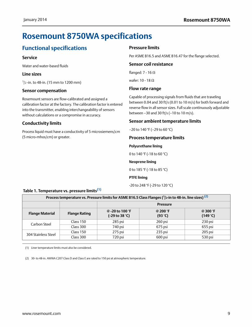
Table 1. Temperature vs. pressure limits(1)
Process temperature vs. Pressure limits for ASME B16.5 Class Flanges (1/2-in to 48-in. line sizes) (2)
Pressure
Flange Material Flange Rating@ -20 to 100 °F(-29 to 38 °C)
@ 200 °F(93 °C)
@ 300 °F(149 °C)
Carbon SteelClass 150 285 psi 260 psi 230 psiClass 300 740 psi 675 psi 655 psi
304 Stainless SteelClass 150 275 psi 235 psi 205 psiClass 300 720 psi 600 psi 530 psi
(1) Liner temperature limits must also be considered.
(2) 30- to 48-in. AWWA C207 Class D and Class E are rated to 150 psi at atmospheric temperature.
10
Rosemount 8750WA January 2014
www.rosemount.com
Optional discrete output function (AX)
Externally powered at 5 to 24 VDC, transistor switch closure up to indicate either:
Reverse flow: Activates switch closure output when reverse flow is detected. The reverse flow rate is displayed.
Zero flow: Activates switch closure output when flow goes to 0 ft/s.
Empty pipe:Activates switch closure output when an empty pipe condition is detected.
Transmitter faults:Activates switch closure output when a transmitter fault is detected.
Flow limits (2):Activates switch closure output when the transmitter measures a flow rate that meets the conditions established for this alert. There are two independent flow limit alerts that can be configured as discrete outputs.
Totalizer limit:Activates switch closure output when the transmitter measures a total flow that meets the conditions established for this alert.
Diagnostic status:Activates switch closure output when the transmitter detects a condition that meets the configured criteria of this output.
Optional digital input function
Externally powered at 5 to 24 VDC, transistor switch closure up to indicate either:
Net total reset: Resets the net totalizer value to zero.
Positive Zero Return (PZR): Simulates zero-flow condition.
Output testing
Analog output testTransmitter may be commanded to supply a specified current between 3.5 and 23 mA.
Pulse output testTransmitter may be commanded to supply a specified frequency between 1 and 10,000 Hz.
Security lockout
Security lockout switch on the electronics board can be set to deactivate all LOI and HART-based communicator functions to protect configuration variables from unwanted or accidental change.
8732 LOI lockoutAll optical switches on the display can be locked locally from the display layout configuration screen by holding the upper right optical switch for 10 seconds. The display can be reactivated holding the same switch for 10 seconds.
Submergence protection (sensor) - SA/SB/SC/SD/SE/SF options
IP68. Continuous submergence to 30 ft. (10 m). Requires conduit entries of the sensor remote junction box be properly sealed to prevent water ingress. This requires the user to install sealed IP68 approved cable glands, conduit connections, or conduit plugs.
Option Codes SA, SB, SC, SD, SE, and SF provide a pre-wired potted and sealed junction box to prevent the ingress of water. These options still require the use of sealed conduits to meet IP68 protection requirements.
Example of a protection category:
Identity letters - IPFirst identity number - 6(1)
Second identity number - 8(2)
(1) Protection against the entry of dust (dust-proof). Complete contact prevention.
(2) The enclosure is suitable for constant submersion in water under given conditions which are determined by the manufacturer (submersion).
11
Rosemount 8750WAJanuary 2014
www.rosemount.com
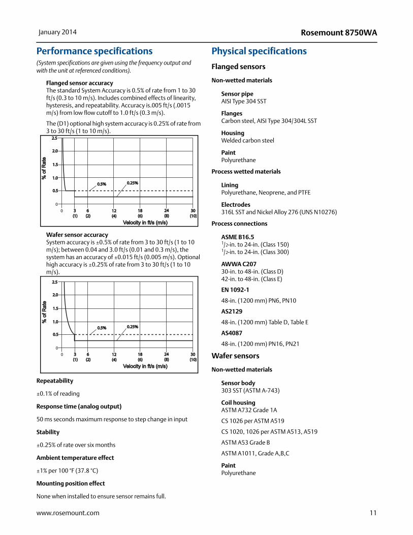
Performance specifications(System specifications are given using the frequency output and with the unit at referenced conditions).
Flanged sensor accuracyThe standard System Accuracy is 0.5% of rate from 1 to 30 ft/s (0.3 to 10 m/s). Includes combined effects of linearity, hysteresis, and repeatability. Accuracy is.005 ft/s (.0015 m/s) from low flow cutoff to 1.0 ft/s (0.3 m/s).
The (D1) optional high system accuracy is 0.25% of rate from 3 to 30 ft/s (1 to 10 m/s).
Wafer sensor accuracySystem accuracy is ±0.5% of rate from 3 to 30 ft/s (1 to 10 m/s); between 0.04 and 3.0 ft/s (0.01 and 0.3 m/s), the system has an accuracy of ±0.015 ft/s (0.005 m/s). Optional high accuracy is ±0.25% of rate from 3 to 30 ft/s (1 to 10 m/s).
Repeatability
±0.1% of reading
Response time (analog output)
50 ms seconds maximum response to step change in input
Stability
±0.25% of rate over six months
Ambient temperature effect
±1% per 100 °F (37.8 °C)
Mounting position effect
None when installed to ensure sensor remains full.
Physical specifications
Flanged sensors
Non-wetted materials
Sensor pipeAISI Type 304 SST
FlangesCarbon steel, AISI Type 304/304L SST
HousingWelded carbon steel
PaintPolyurethane
Process wetted materials
LiningPolyurethane, Neoprene, and PTFE
Electrodes316L SST and Nickel Alloy 276 (UNS N10276)
Process connections
ASME B16.51/2-in. to 24-in. (Class 150)1/2-in. to 24-in. (Class 300)
AWWA C207 30-in. to 48-in. (Class D)42-in. to 48-in. (Class E)
EN 1092-1
48-in. (1200 mm) PN6, PN10
AS2129
48-in. (1200 mm) Table D, Table E
AS4087
48-in. (1200 mm) PN16, PN21
Wafer sensors
Non-wetted materials
Sensor body303 SST (ASTM A-743)
Coil housingASTM A732 Grade 1A
CS 1026 per ASTM A519
CS 1020, 1026 per ASTM A513, A519
ASTM A53 Grade B
ASTM A1011, Grade A,B,C
PaintPolyurethane
0
0.50.5
1.01.0
1.51.5
2.02.0
2.52.5
0 3 3 (1)(1)
6 6 (2)(2)
12 12 (4)(4)
18 18 (6)(6)
24 24 (8)(8)
30 30 (10)(10)
Velocity in ft/s (m/s)Velocity in ft/s (m/s)
% o
f Rat
e%
of R
ate
0.5%0.5% 0.25%0.25%
0
0.50.5
1.01.0
1.51.5
2.02.0
2.52.5
0 3 3 (1)(1)
6 6 (2)(2)
12 12 (4)(4)
18 18 (6)(6)
24 24 (8)(8)
30 30 (10)(10)
Velocity in ft/s (m/s)Velocity in ft/s (m/s)
% o
f Rat
e%
of R
ate
0.5%0.5% 0.25%0.25%
12
Rosemount 8750WA January 2014
www.rosemount.com
Process-wetted materials
LiningPTFE
Electrodes316L SST, Nickel Alloy 276 (UNS N10276)
Process connections
Mounts between these Flange ConfigurationsASME B16.5: 1/2-in. to 8-in. Class 150, 300
Studs, nuts, and washersASME B16.51/2-in. and 1-in. (15 mm and 25 mm):316 SST, ASTM A193, Grade B8M, Class 1 threaded mounting studs; ASTM A194, Grade 8M heavy hex nuts; SAE per ANSI B18.2.1, Type A, Series N flat washers.
1/2-in. to 8-in. (40 mm to 200 mm):CS, ASTM A193, Grade B7, Class 1 threaded mounting studs; ASTM A194, Grade 2H heavy hex nuts; SAE per ANSI B18.2.1, Type A, Series N flat washers; all items clear, chromate zinc-plated.
Electrical connections
Two 1/2–14 NPT connections with number 8 screw terminals are provided in the terminal enclosure for electrical wiring.
Process reference electrode
A process reference electrode is installed similarly to the measurement electrodes through the lining of the sensor. It will be made of the same material as the measurement electrodes.
Grounding rings - (optional)
Grounding rings are installed between the flange and the sensor face on both ends of the sensor. Single ground rings can be installed on either end of the sensor. They have an I.D. slightly larger than the sensor I.D. and an external tab to attach ground wiring. Grounding rings are available in 316L SST and Nickel Alloy 276 (UNS N10276).
Lining protectors - (optional)
Lining protectors are installed on the flanges at both ends of the sensor. The leading edge of lining material is protected by the lining protector; lining protectors cannot be removed once they are installed. Lining protectors are available in 316L SST and Nickel Alloy 276 (UNS N10276).
Dimensions
See Figure 8, Figure 9, and Table 3.
Weight
See Table 2 and Table 3
Transmitters
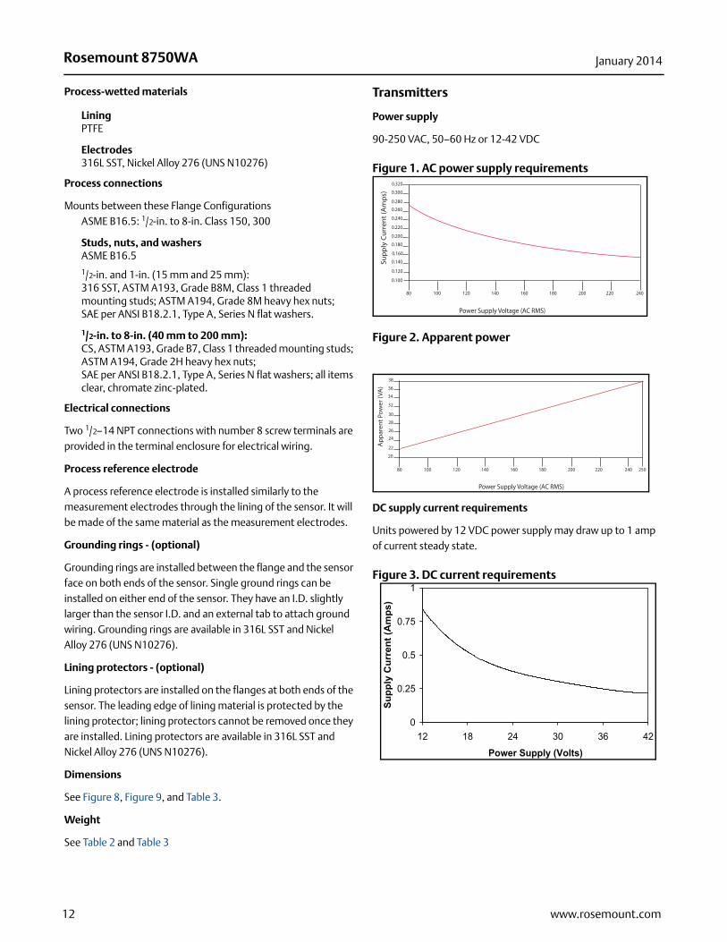
Power supply
90-250 VAC, 50–60 Hz or 12-42 VDC
Figure 1. AC power supply requirements
Figure 2. Apparent power
DC supply current requirements
Units powered by 12 VDC power supply may draw up to 1 amp of current steady state.
Figure 3. DC current requirements
Sup
ply
Cur
rent
(Am
ps)
0.100
0.120
0.140
0.180
0.200
0.220
0.240
0.260
0.280
0.300
0.320
0.160
80 100 120 140 160 180 200 220 240
Power Supply Voltage (AC RMS)
80 100 120 140 160 180 200 220 240
Power Supply Voltage (AC RMS)
20
22
24
26
28
30
32
34
36
38A
ppar
ent P
ower
(VA
)
250
0
0.25
0.5
0.75
1
12 18 24 30 36 42
Power Supply (Volts)
Supp
ly C
urre
nt (A
mps
)
13
Rosemount 8750WAJanuary 2014
www.rosemount.com
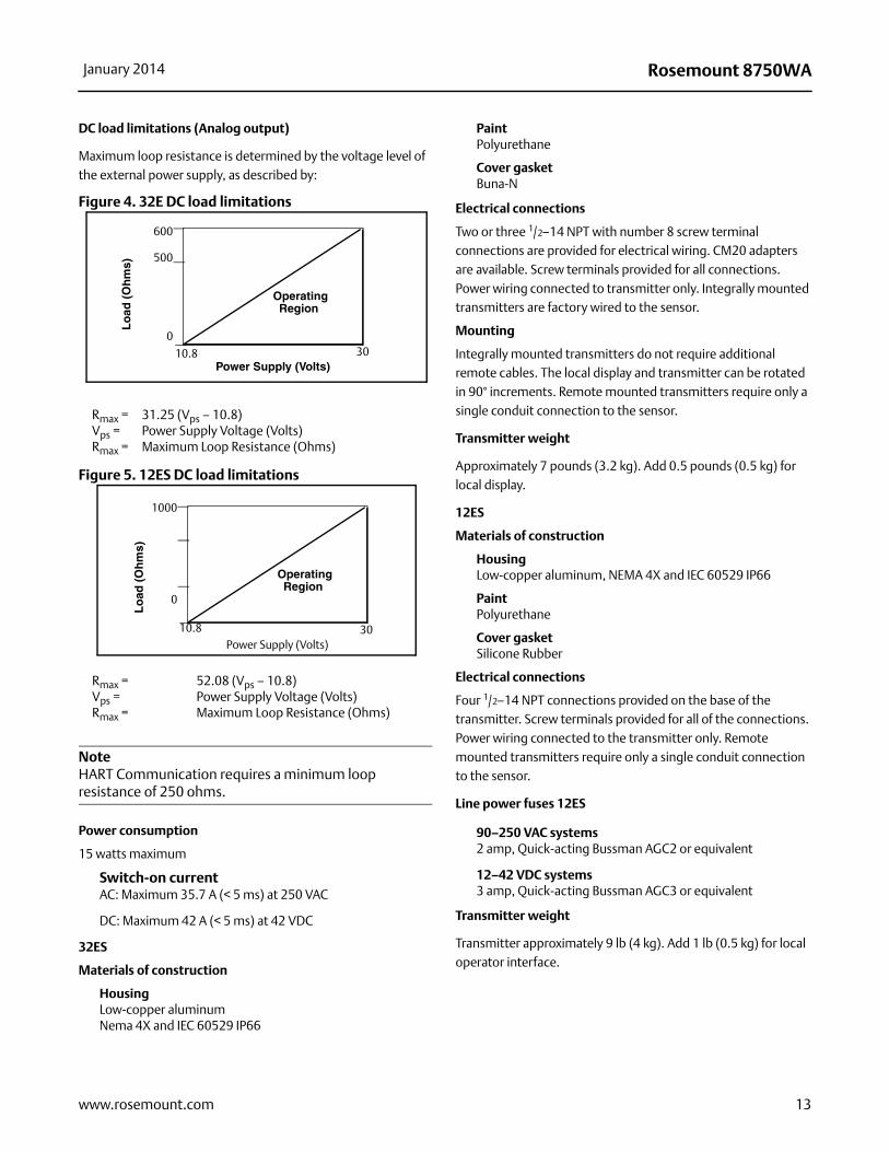
DC load limitations (Analog output)
Maximum loop resistance is determined by the voltage level of the external power supply, as described by:
Figure 4. 32E DC load limitations
Figure 5. 12ES DC load limitations
NoteHART Communication requires a minimum loop resistance of 250 ohms.
Power consumption
15 watts maximum
Switch-on currentAC: Maximum 35.7 A (< 5 ms) at 250 VAC
DC: Maximum 42 A (< 5 ms) at 42 VDC
32ES
Materials of construction
HousingLow-copper aluminumNema 4X and IEC 60529 IP66
PaintPolyurethane
Cover gasketBuna-N
Electrical connections
Two or three 1/2–14 NPT with number 8 screw terminal connections are provided for electrical wiring. CM20 adapters are available. Screw terminals provided for all connections. Power wiring connected to transmitter only. Integrally mounted transmitters are factory wired to the sensor.
Mounting
Integrally mounted transmitters do not require additional remote cables. The local display and transmitter can be rotated in 90° increments. Remote mounted transmitters require only a single conduit connection to the sensor.
Transmitter weight
Approximately 7 pounds (3.2 kg). Add 0.5 pounds (0.5 kg) for local display.
12ES
Materials of construction
HousingLow-copper aluminum, NEMA 4X and IEC 60529 IP66
PaintPolyurethane
Cover gasketSilicone Rubber
Electrical connections
Four 1/2–14 NPT connections provided on the base of the transmitter. Screw terminals provided for all of the connections. Power wiring connected to the transmitter only. Remote mounted transmitters require only a single conduit connection to the sensor.
Line power fuses 12ES
90–250 VAC systems2 amp, Quick-acting Bussman AGC2 or equivalent
12–42 VDC systems3 amp, Quick-acting Bussman AGC3 or equivalent
Transmitter weight
Transmitter approximately 9 lb (4 kg). Add 1 lb (0.5 kg) for local operator interface.
Rmax = 31.25 (Vps – 10.8)Vps = Power Supply Voltage (Volts)Rmax = Maximum Loop Resistance (Ohms)
Rmax = 52.08 (Vps – 10.8)Vps = Power Supply Voltage (Volts)Rmax = Maximum Loop Resistance (Ohms)
Power Supply (Volts)
Lo
ad (
Oh
ms)
OperatingRegion
600
500
0
10.8 30
Power Supply (Volts)
Lo
ad (
Oh
ms)
OperatingRegion
1000
0
10.8 30