Embed Size (px)
Citation preview
Product Data Sheet00813-0100-4308, Rev DD
December 2019
Rosemount™ 3308 Series Wireless GuidedWave Radar, 3308A
■ World’s first true wireless Guided Wave Radar based on field proven, market leading technologies
■ Accurate, direct level and interface measurements virtually unaffected by process conditions
■ Fast and simple commissioning with self-organizing wireless network, intuitive user interface and cut-to-fit probes
■ Minimized maintenance with no wires, no moving parts, no re-calibration, long battery life and advanced diagnostics for betterprocess insight
Introduction
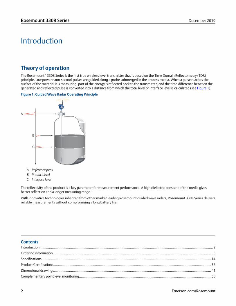
Theory of operationThe Rosemount™ 3308 Series is the first true wireless level transmitter that is based on the Time Domain Reflectometry (TDR)principle. Low power nano-second-pulses are guided along a probe submerged in the process media. When a pulse reaches thesurface of the material it is measuring, part of the energy is reflected back to the transmitter, and the time difference between thegenerated and reflected pulse is converted into a distance from which the total level or interface level is calculated (see Figure 1).
Figure 1: Guided Wave Radar Operating Principle
A. Reference peakB. Product levelC. Interface level
The reflectivity of the product is a key parameter for measurement performance. A high dielectric constant of the media givesbetter reflection and a longer measuring range.
With innovative technologies inherited from other market leading Rosemount guided wave radars, Rosemount 3308 Series deliversreliable measurements without compromising a long battery life.
ContentsIntroduction...................................................................................................................................................................................... 2
Ordering information........................................................................................................................................................................ 5
Specifications.................................................................................................................................................................................. 14
Product Certifications......................................................................................................................................................................36
Dimensional drawings..................................................................................................................................................................... 41
Complementary point level monitoring...........................................................................................................................................50
Rosemount 3308 Series December 2019
2 Emerson.com/Rosemount
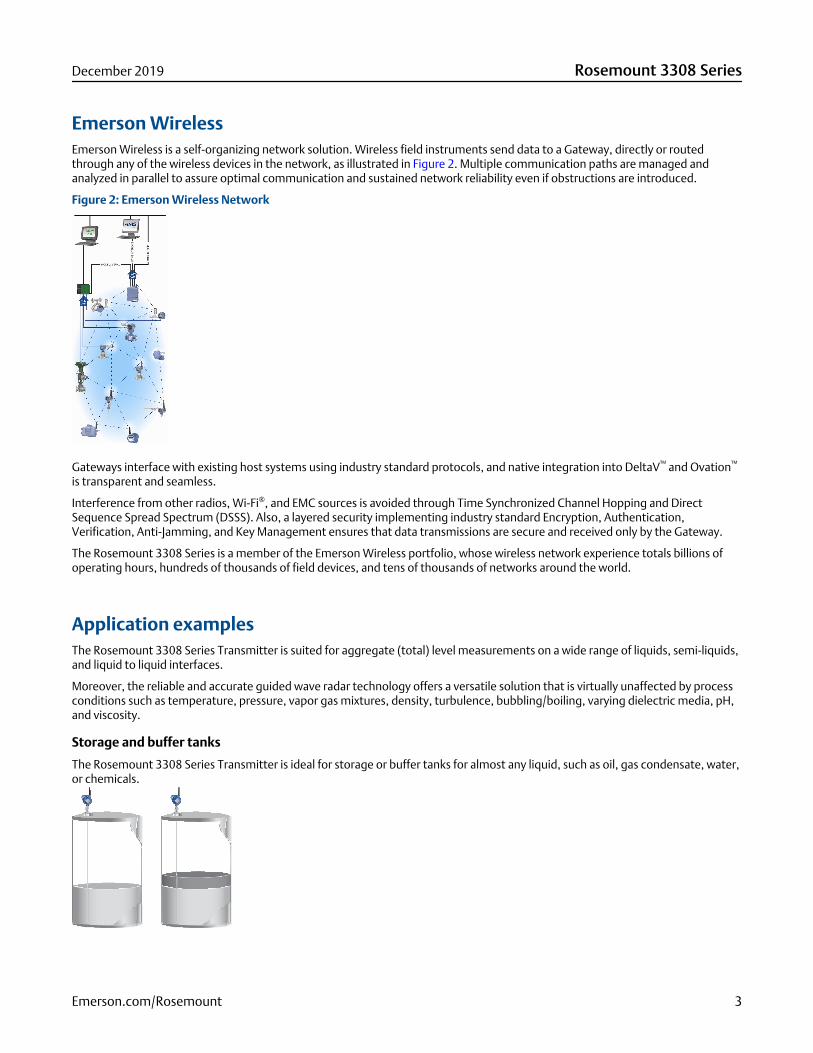
Emerson WirelessEmerson Wireless is a self-organizing network solution. Wireless field instruments send data to a Gateway, directly or routedthrough any of the wireless devices in the network, as illustrated in Figure 2. Multiple communication paths are managed andanalyzed in parallel to assure optimal communication and sustained network reliability even if obstructions are introduced.
Figure 2: Emerson Wireless Network
Gateways interface with existing host systems using industry standard protocols, and native integration into DeltaV™ and Ovation™
is transparent and seamless.
Interference from other radios, Wi-Fi®, and EMC sources is avoided through Time Synchronized Channel Hopping and DirectSequence Spread Spectrum (DSSS). Also, a layered security implementing industry standard Encryption, Authentication,Verification, Anti-Jamming, and Key Management ensures that data transmissions are secure and received only by the Gateway.
The Rosemount 3308 Series is a member of the Emerson Wireless portfolio, whose wireless network experience totals billions ofoperating hours, hundreds of thousands of field devices, and tens of thousands of networks around the world.
Application examplesThe Rosemount 3308 Series Transmitter is suited for aggregate (total) level measurements on a wide range of liquids, semi-liquids,and liquid to liquid interfaces.
Moreover, the reliable and accurate guided wave radar technology offers a versatile solution that is virtually unaffected by processconditions such as temperature, pressure, vapor gas mixtures, density, turbulence, bubbling/boiling, varying dielectric media, pH,and viscosity.
Storage and buffer tanks
The Rosemount 3308 Series Transmitter is ideal for storage or buffer tanks for almost any liquid, such as oil, gas condensate, water,or chemicals.
December 2019 Rosemount 3308 Series
Emerson.com/Rosemount 3
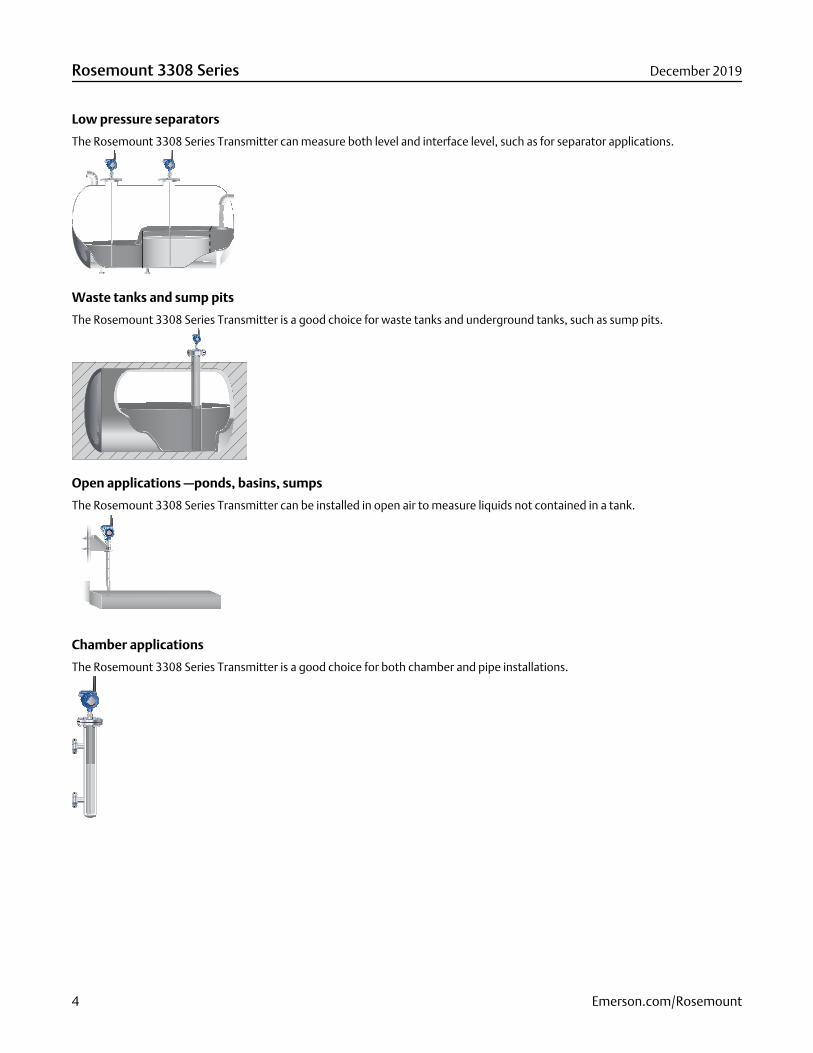
Low pressure separators
The Rosemount 3308 Series Transmitter can measure both level and interface level, such as for separator applications.
Waste tanks and sump pits
The Rosemount 3308 Series Transmitter is a good choice for waste tanks and underground tanks, such as sump pits.
Open applications —ponds, basins, sumps
The Rosemount 3308 Series Transmitter can be installed in open air to measure liquids not contained in a tank.
Chamber applications
The Rosemount 3308 Series Transmitter is a good choice for both chamber and pipe installations.
Rosemount 3308 Series December 2019
4 Emerson.com/Rosemount
Ordering information
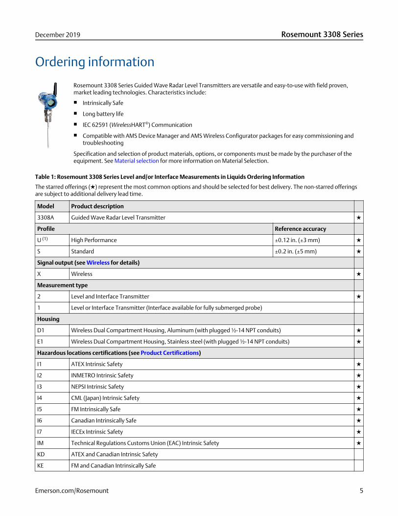
Rosemount 3308 Series Guided Wave Radar Level Transmitters are versatile and easy-to-use with field proven,market leading technologies. Characteristics include:
■ Intrinsically Safe
■ Long battery life
■ IEC 62591 (WirelessHART®) Communication
■ Compatible with AMS Device Manager and AMS Wireless Configurator packages for easy commissioning andtroubleshooting
Specification and selection of product materials, options, or components must be made by the purchaser of theequipment. See Material selection for more information on Material Selection.
Table 1: Rosemount 3308 Series Level and/or Interface Measurements in Liquids Ordering Information
The starred offerings (★) represent the most common options and should be selected for best delivery. The non-starred offeringsare subject to additional delivery lead time.
Model Product description
3308A Guided Wave Radar Level Transmitter ★
Profile Reference accuracy
U (1) High Performance ±0.12 in. (±3 mm) ★
S Standard ±0.2 in. (±5 mm) ★
Signal output (see Wireless for details)
X Wireless ★
Measurement type
2 Level and Interface Transmitter ★
1 Level or Interface Transmitter (Interface available for fully submerged probe)
Housing
D1 Wireless Dual Compartment Housing, Aluminum (with plugged ½-14 NPT conduits) ★
E1 Wireless Dual Compartment Housing, Stainless steel (with plugged ½-14 NPT conduits) ★
Hazardous locations certifications (see Product Certifications)
I1 ATEX Intrinsic Safety ★
I2 INMETRO Intrinsic Safety ★
I3 NEPSI Intrinsic Safety ★
I4 CML (Japan) Intrinsic Safety ★
I5 FM Intrinsically Safe ★
I6 Canadian Intrinsically Safe ★
I7 IECEx Intrinsic Safety ★
IM Technical Regulations Customs Union (EAC) Intrinsic Safety ★
KD ATEX and Canadian Intrinsic Safety
KE FM and Canadian Intrinsically Safe
December 2019 Rosemount 3308 Series
Emerson.com/Rosemount 5
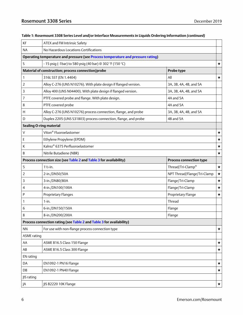
Table 1: Rosemount 3308 Series Level and/or Interface Measurements in Liquids Ordering Information (continued)
KF ATEX and FM Intrinsic Safety
NA No Hazardous Locations Certifications
Operating temperature and pressure (see Process temperature and pressure rating)
S - 15 psig (-1bar) to 580 psig (40 bar) @ 302 °F (150 °C) ★
Material of construction; process connection/probe Probe type
1 316L SST (EN 1.4404) All ★
2 Alloy C-276 (UNS N10276). With plate design if flanged version. 3A, 3B, 4A, 4B, and 5A
3 Alloy 400 (UNS N04400). With plate design if flanged version. 3A, 3B, 4A, 4B, and 5A
7 PTFE covered probe and flange. With plate design. 4A and 5A
8 PTFE covered probe 4A and 5A
H Alloy C-276 (UNS N10276) process connection, flange, and probe 3A, 3B, 4A, 4B, and 5A
D Duplex 2205 (UNS S31803) process connection, flange, and probe 4B and 5A
Sealing O-ring material
V Viton® Fluoroelastomer ★
E Ethylene Propylene (EPDM) ★
K Kalrez® 6375 Perfluoroelastomer ★
B Nitrile Butadiene (NBR) ★
Process connection size (see Table 2 and Table 3 for availability) Process connection type
5 1½-in. Thread/Tri-Clamp® ★
2 2-in./DN50/50A NPT Thread/Flange/Tri-Clamp ★
3 3-in./DN80/80A Flange/Tri-Clamp ★
4 4-in./DN100/100A Flange/Tri-Clamp ★
P Proprietary Flanges Proprietary Flange ★
1 1-in. Thread
6 6-in./DN150/150A Flange
8 8-in./DN200/200A Flange
Process connection rating (see Table 2 and Table 3 for availability)
NN For use with non-flange process connection type ★
ASME rating
AA ASME B16.5 Class 150 Flange ★
AB ASME B16.5 Class 300 Flange ★
EN rating
DA EN1092-1 PN16 Flange ★
DB EN1092-1 PN40 Flange ★
JIS rating
JA JIS B2220 10K Flange ★
Rosemount 3308 Series December 2019
6 Emerson.com/Rosemount
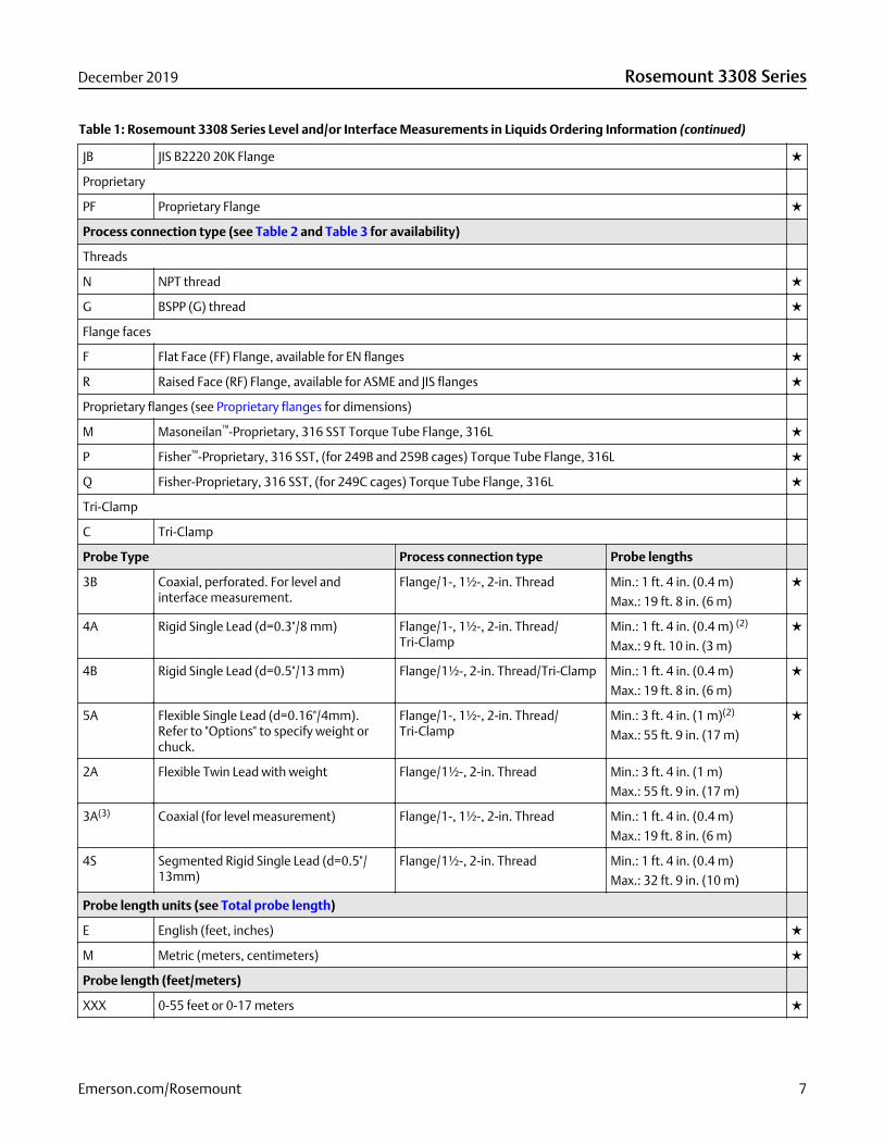
Table 1: Rosemount 3308 Series Level and/or Interface Measurements in Liquids Ordering Information (continued)
JB JIS B2220 20K Flange ★
Proprietary
PF Proprietary Flange ★
Process connection type (see Table 2 and Table 3 for availability)
Threads
N NPT thread ★
G BSPP (G) thread ★
Flange faces
F Flat Face (FF) Flange, available for EN flanges ★
R Raised Face (RF) Flange, available for ASME and JIS flanges ★
Proprietary flanges (see Proprietary flanges for dimensions)
M Masoneilan™-Proprietary, 316 SST Torque Tube Flange, 316L ★
P Fisher™-Proprietary, 316 SST, (for 249B and 259B cages) Torque Tube Flange, 316L ★
Q Fisher-Proprietary, 316 SST, (for 249C cages) Torque Tube Flange, 316L ★
Tri-Clamp
C Tri-Clamp
Probe Type Process connection type Probe lengths
3B Coaxial, perforated. For level andinterface measurement.
Flange/1-, 1½-, 2-in. Thread Min.: 1 ft. 4 in. (0.4 m)
Max.: 19 ft. 8 in. (6 m)
★
4A Rigid Single Lead (d=0.3"/8 mm) Flange/1-, 1½-, 2-in. Thread/Tri-Clamp
Min.: 1 ft. 4 in. (0.4 m) (2)
Max.: 9 ft. 10 in. (3 m)
★
4B Rigid Single Lead (d=0.5"/13 mm) Flange/1½-, 2-in. Thread/Tri-Clamp Min.: 1 ft. 4 in. (0.4 m)
Max.: 19 ft. 8 in. (6 m)
★
5A Flexible Single Lead (d=0.16"/4mm).Refer to "Options" to specify weight orchuck.
Flange/1-, 1½-, 2-in. Thread/Tri-Clamp
Min.: 3 ft. 4 in. (1 m)(2)
Max.: 55 ft. 9 in. (17 m)
★
2A Flexible Twin Lead with weight Flange/1½-, 2-in. Thread Min.: 3 ft. 4 in. (1 m)
Max.: 55 ft. 9 in. (17 m)
3A(3) Coaxial (for level measurement) Flange/1-, 1½-, 2-in. Thread Min.: 1 ft. 4 in. (0.4 m)
Max.: 19 ft. 8 in. (6 m)
4S Segmented Rigid Single Lead (d=0.5"/13mm)
Flange/1½-, 2-in. Thread Min.: 1 ft. 4 in. (0.4 m)
Max.: 32 ft. 9 in. (10 m)
Probe length units (see Total probe length)
E English (feet, inches) ★
M Metric (meters, centimeters) ★
Probe length (feet/meters)
XXX 0-55 feet or 0-17 meters ★
December 2019 Rosemount 3308 Series
Emerson.com/Rosemount 7
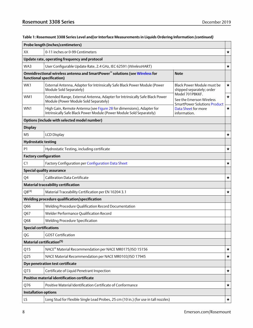
Table 1: Rosemount 3308 Series Level and/or Interface Measurements in Liquids Ordering Information (continued)
Probe length (inches/centimeters)
XX 0-11 inches or 0-99 Centimeters ★
Update rate, operating frequency and protocol
WA3 User Configurable Update Rate, 2.4 GHz, IEC 62591 (WirelessHART) ★
Omnidirectional wireless antenna and SmartPower™ solutions (see Wireless forfunctional specification)
Note
WK1 External Antenna, Adapter for Intrinsically Safe Black Power Module (PowerModule Sold Separately)
Black Power Module must beshipped separately; orderModel 701PBKKF.
See the Emerson WirelessSmartPower Solutions ProductData Sheet for moreinformation.
★
WM1 Extended Range, External Antenna, Adapter for Intrinsically Safe Black PowerModule (Power Module Sold Separately)
★
WN1 High Gain, Remote Antenna (see Figure 28 for dimensions), Adapter forIntrinsically Safe Black Power Module (Power Module Sold Separately)
★
Options (include with selected model number)
Display
M5 LCD Display ★
Hydrostatic testing
P1 Hydrostatic Testing, including certificate ★
Factory configuration
C1 Factory Configuration per Configuration Data Sheet ★
Special quality assurance
Q4 Calibration Data Certificate ★
Material traceability certification
Q8(4) Material Traceability Certification per EN 10204 3.1 ★
Welding procedure qualification/specification
Q66 Welding Procedure Qualification Record Documentation
Q67 Welder Performance Qualification Record
Q68 Welding Procedure Specification
Special certifications
QG GOST Certification
Material certification(5)
Q15 NACE® Material Recommendation per NACE MR0175/ISO 15156 ★
Q25 NACE Material Recommendation per NACE MR0103/ISO 17945 ★
Dye penetration test certificate
Q73 Certificate of Liquid Penetrant Inspection ★
Positive material identification certificate
Q76 Positive Material Identification Certificate of Conformance ★
Installation options
LS Long Stud for Flexible Single Lead Probes, 25 cm (10 in.) (for use in tall nozzles) ★
Rosemount 3308 Series December 2019
8 Emerson.com/Rosemount
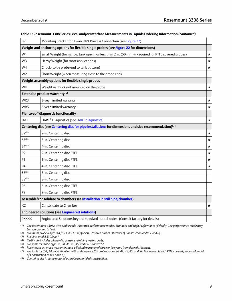
Table 1: Rosemount 3308 Series Level and/or Interface Measurements in Liquids Ordering Information (continued)
BR Mounting Bracket for 1½-in. NPT Process Connection (see Figure 27)
Weight and anchoring options for flexible single probes (see Figure 22 for dimensions)
W1 Small Weight (for narrow tank openings less than 2 in. (50 mm)) (Required for PTFE covered probes) ★
W3 Heavy Weight (for most applications) ★
W4 Chuck (to tie probe end to tank bottom) ★
W2 Short Weight (when measuring close to the probe end)
Weight assembly options for flexible single probes
WU Weight or chuck not mounted on the probe ★
Extended product warranty(6)
WR3 3-year limited warranty ★
WR5 5-year limited warranty ★
Plantweb™ diagnostic functionality
DA1 HART® Diagnostics (see HART diagnostics) ★
Centering disc (see Centering disc for pipe installations for dimensions and size recommendation)(7)
S2(8) 2-in. Centering disc ★
S3(8) 3-in. Centering disc ★
S4(8) 4-in. Centering disc ★
P2 2-in. Centering disc PTFE ★
P3 3-in. Centering disc PTFE ★
P4 4-in. Centering disc PTFE ★
S6(8) 6-in. Centering disc
S8(8) 8-in. Centering disc
P6 6-in. Centering disc PTFE
P8 8-in. Centering disc PTFE
Assemble/consolidate to chamber (see Installation in still pipe/chamber)
XC Consolidate to Chamber ★
Engineered solutions (see Engineered solutions)
PXXXX Engineered Solutions beyond standard model codes. (Consult factory for details)
(1) The Rosemount 3308A with profile code U has two performance modes: Standard and High Performance (default). The performance mode maybe reconfigured in field.
(2) Minimum probe length is 4 ft. 11 in. (1.5 m) for PTFE covered probes (Material of Construction codes 7 and 8).(3) Requires model 3308Axx1.(4) Certificate includes all metallic pressure retaining wetted parts.(5) Available for Probe Type 3A, 3B, 4A, 4B, 4S, and PTFE-coated 5A.(6) Rosemount extended warranties have a limited warranty of three or five years from date of shipment.(7) Available for SST, Alloy C-276, Alloy 400, and Duplex 2205 probes, types 2A, 4A, 4B, 4S, and 5A. Not available with PTFE covered probes (Material
of Construction codes 7 and 8).(8) Centering disc in same material as probe material of construction.
December 2019 Rosemount 3308 Series
Emerson.com/Rosemount 9
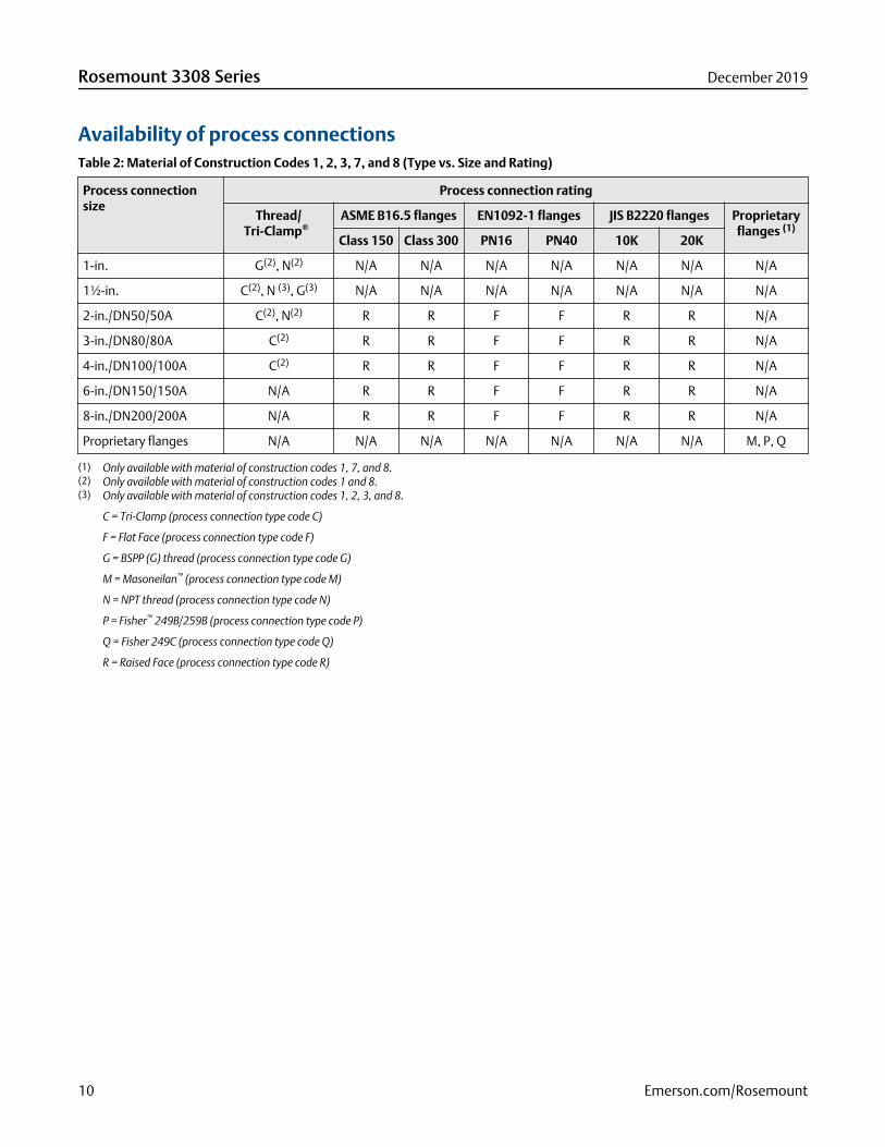
Availability of process connectionsTable 2: Material of Construction Codes 1, 2, 3, 7, and 8 (Type vs. Size and Rating)
Process connectionsize
Process connection rating
Thread/Tri-Clamp®
ASME B16.5 flanges EN1092-1 flanges JIS B2220 flanges Proprietaryflanges (1)
Class 150 Class 300 PN16 PN40 10K 20K
1-in. G(2), N(2) N/A N/A N/A N/A N/A N/A N/A
1½-in. C(2), N (3), G(3) N/A N/A N/A N/A N/A N/A N/A
2-in./DN50/50A C(2), N(2) R R F F R R N/A
3-in./DN80/80A C(2) R R F F R R N/A
4-in./DN100/100A C(2) R R F F R R N/A
6-in./DN150/150A N/A R R F F R R N/A
8-in./DN200/200A N/A R R F F R R N/A
Proprietary flanges N/A N/A N/A N/A N/A N/A N/A M, P, Q
(1) Only available with material of construction codes 1, 7, and 8.(2) Only available with material of construction codes 1 and 8.(3) Only available with material of construction codes 1, 2, 3, and 8.
C = Tri-Clamp (process connection type code C)
F = Flat Face (process connection type code F)
G = BSPP (G) thread (process connection type code G)
M = Masoneilan™ (process connection type code M)
N = NPT thread (process connection type code N)
P = Fisher™ 249B/259B (process connection type code P)
Q = Fisher 249C (process connection type code Q)
R = Raised Face (process connection type code R)
Rosemount 3308 Series December 2019
10 Emerson.com/Rosemount
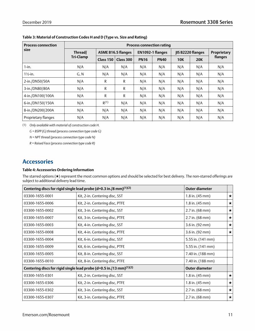
Table 3: Material of Construction Codes H and D (Type vs. Size and Rating)
Process connectionsize
Process connection rating
Thread/Tri-Clamp
ASME B16.5 flanges EN1092-1 flanges JIS B2220 flanges Proprietaryflanges
Class 150 Class 300 PN16 PN40 10K 20K
1-in. N/A N/A N/A N/A N/A N/A N/A N/A
1½-in. G, N N/A N/A N/A N/A N/A N/A N/A
2-in./DN50/50A N/A R R N/A N/A N/A N/A N/A
3-in./DN80/80A N/A R R N/A N/A N/A N/A N/A
4-in./DN100/100A N/A R R N/A N/A N/A N/A N/A
6-in./DN150/150A N/A R(1) N/A N/A N/A N/A N/A N/A
8-in./DN200/200A N/A N/A N/A N/A N/A N/A N/A N/A
Proprietary flanges N/A N/A N/A N/A N/A N/A N/A N/A
(1) Only available with material of construction code H.
G = BSPP (G) thread (process connection type code G)
N = NPT thread (process connection type code N)
R = Raised Face (process connection type code R)
AccessoriesTable 4: Accessories Ordering Information
The starred options (★) represent the most common options and should be selected for best delivery. The non-starred offerings aresubject to additional delivery lead time.
Centering discs for rigid single lead probe (d=0.3 in./8 mm)(1)(2) Outer diameter
03300-1655-0001 Kit, 2-in. Centering disc, SST 1.8 in. (45 mm) ★
03300-1655-0006 Kit, 2-in. Centering disc, PTFE 1.8 in. (45 mm) ★
03300-1655-0002 Kit, 3-in. Centering disc, SST 2.7 in. (68 mm) ★
03300-1655-0007 Kit, 3-in. Centering disc, PTFE 2.7 in. (68 mm) ★
03300-1655-0003 Kit, 4-in. Centering disc, SST 3.6 in. (92 mm) ★
03300-1655-0008 Kit, 4-in. Centering disc, PTFE 3.6 in. (92 mm) ★
03300-1655-0004 Kit, 6-in. Centering disc, SST 5.55 in. (141 mm)
03300-1655-0009 Kit, 6-in. Centering disc, PTFE 5.55 in. (141 mm)
03300-1655-0005 Kit, 8-in. Centering disc, SST 7.40 in. (188 mm)
03300-1655-0010 Kit, 8-in. Centering disc, PTFE 7.40 in. (188 mm)
Centering discs for rigid single lead probe (d=0.5 in./13 mm)(1)(2) Outer diameter
03300-1655-0301 Kit, 2-in. Centering disc, SST 1.8 in. (45 mm) ★
03300-1655-0306 Kit, 2-in. Centering disc, PTFE 1.8 in. (45 mm) ★
03300-1655-0302 Kit, 3-in. Centering disc, SST 2.7 in. (68 mm) ★
03300-1655-0307 Kit, 3-in. Centering disc, PTFE 2.7 in. (68 mm) ★
December 2019 Rosemount 3308 Series
Emerson.com/Rosemount 11
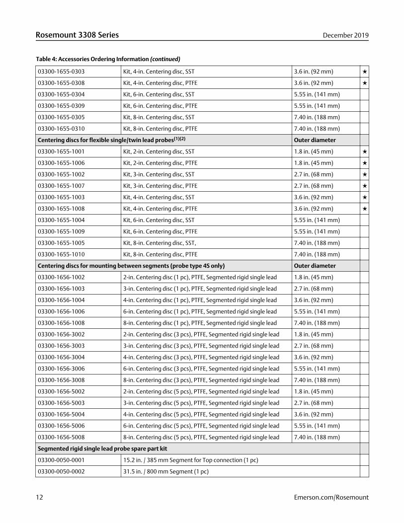
Table 4: Accessories Ordering Information (continued)
03300-1655-0303 Kit, 4-in. Centering disc, SST 3.6 in. (92 mm) ★
03300-1655-0308 Kit, 4-in. Centering disc, PTFE 3.6 in. (92 mm) ★
03300-1655-0304 Kit, 6-in. Centering disc, SST 5.55 in. (141 mm)
03300-1655-0309 Kit, 6-in. Centering disc, PTFE 5.55 in. (141 mm)
03300-1655-0305 Kit, 8-in. Centering disc, SST 7.40 in. (188 mm)
03300-1655-0310 Kit, 8-in. Centering disc, PTFE 7.40 in. (188 mm)
Centering discs for flexible single/twin lead probes(1)(2) Outer diameter
03300-1655-1001 Kit, 2-in. Centering disc, SST 1.8 in. (45 mm) ★
03300-1655-1006 Kit, 2-in. Centering disc, PTFE 1.8 in. (45 mm) ★
03300-1655-1002 Kit, 3-in. Centering disc, SST 2.7 in. (68 mm) ★
03300-1655-1007 Kit, 3-in. Centering disc, PTFE 2.7 in. (68 mm) ★
03300-1655-1003 Kit, 4-in. Centering disc, SST 3.6 in. (92 mm) ★
03300-1655-1008 Kit, 4-in. Centering disc, PTFE 3.6 in. (92 mm) ★
03300-1655-1004 Kit, 6-in. Centering disc, SST 5.55 in. (141 mm)
03300-1655-1009 Kit, 6-in. Centering disc, PTFE 5.55 in. (141 mm)
03300-1655-1005 Kit, 8-in. Centering disc, SST, 7.40 in. (188 mm)
03300-1655-1010 Kit, 8-in. Centering disc, PTFE 7.40 in. (188 mm)
Centering discs for mounting between segments (probe type 4S only) Outer diameter
03300-1656-1002 2-in. Centering disc (1 pc), PTFE, Segmented rigid single lead 1.8 in. (45 mm)
03300-1656-1003 3-in. Centering disc (1 pc), PTFE, Segmented rigid single lead 2.7 in. (68 mm)
03300-1656-1004 4-in. Centering disc (1 pc), PTFE, Segmented rigid single lead 3.6 in. (92 mm)
03300-1656-1006 6-in. Centering disc (1 pc), PTFE, Segmented rigid single lead 5.55 in. (141 mm)
03300-1656-1008 8-in. Centering disc (1 pc), PTFE, Segmented rigid single lead 7.40 in. (188 mm)
03300-1656-3002 2-in. Centering disc (3 pcs), PTFE, Segmented rigid single lead 1.8 in. (45 mm)
03300-1656-3003 3-in. Centering disc (3 pcs), PTFE, Segmented rigid single lead 2.7 in. (68 mm)
03300-1656-3004 4-in. Centering disc (3 pcs), PTFE, Segmented rigid single lead 3.6 in. (92 mm)
03300-1656-3006 6-in. Centering disc (3 pcs), PTFE, Segmented rigid single lead 5.55 in. (141 mm)
03300-1656-3008 8-in. Centering disc (3 pcs), PTFE, Segmented rigid single lead 7.40 in. (188 mm)
03300-1656-5002 2-in. Centering disc (5 pcs), PTFE, Segmented rigid single lead 1.8 in. (45 mm)
03300-1656-5003 3-in. Centering disc (5 pcs), PTFE, Segmented rigid single lead 2.7 in. (68 mm)
03300-1656-5004 4-in. Centering disc (5 pcs), PTFE, Segmented rigid single lead 3.6 in. (92 mm)
03300-1656-5006 6-in. Centering disc (5 pcs), PTFE, Segmented rigid single lead 5.55 in. (141 mm)
03300-1656-5008 8-in. Centering disc (5 pcs), PTFE, Segmented rigid single lead 7.40 in. (188 mm)
Segmented rigid single lead probe spare part kit
03300-0050-0001 15.2 in. / 385 mm Segment for Top connection (1 pc)
03300-0050-0002 31.5 in. / 800 mm Segment (1 pc)
Rosemount 3308 Series December 2019
12 Emerson.com/Rosemount
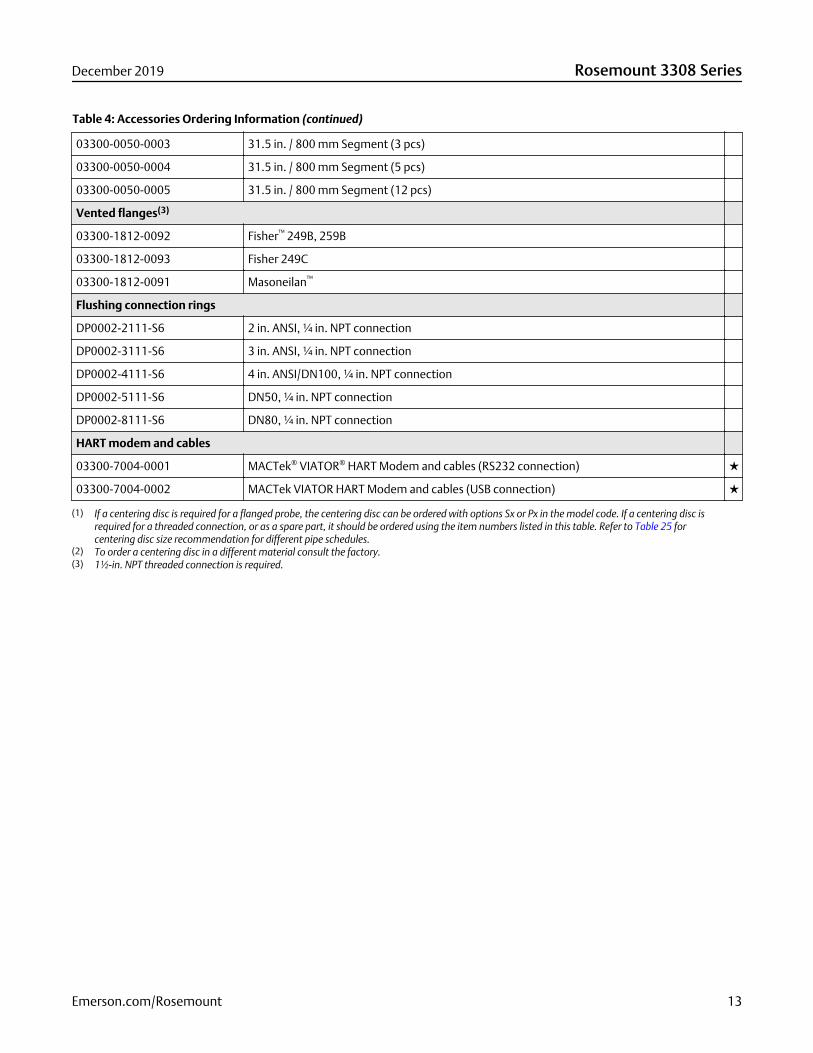
Table 4: Accessories Ordering Information (continued)
03300-0050-0003 31.5 in. / 800 mm Segment (3 pcs)
03300-0050-0004 31.5 in. / 800 mm Segment (5 pcs)
03300-0050-0005 31.5 in. / 800 mm Segment (12 pcs)
Vented flanges(3)
03300-1812-0092 Fisher™ 249B, 259B
03300-1812-0093 Fisher 249C
03300-1812-0091 Masoneilan™
Flushing connection rings
DP0002-2111-S6 2 in. ANSI, ¼ in. NPT connection
DP0002-3111-S6 3 in. ANSI, ¼ in. NPT connection
DP0002-4111-S6 4 in. ANSI/DN100, ¼ in. NPT connection
DP0002-5111-S6 DN50, ¼ in. NPT connection
DP0002-8111-S6 DN80, ¼ in. NPT connection
HART modem and cables
03300-7004-0001 MACTek® VIATOR® HART Modem and cables (RS232 connection) ★
03300-7004-0002 MACTek VIATOR HART Modem and cables (USB connection) ★
(1) If a centering disc is required for a flanged probe, the centering disc can be ordered with options Sx or Px in the model code. If a centering disc isrequired for a threaded connection, or as a spare part, it should be ordered using the item numbers listed in this table. Refer to Table 25 forcentering disc size recommendation for different pipe schedules.
(2) To order a centering disc in a different material consult the factory.(3) 1½-in. NPT threaded connection is required.
December 2019 Rosemount 3308 Series
Emerson.com/Rosemount 13
Specifications
Performance specifications
General
Reference conditions
■ Probe: Flexible single lead
■ Vessel: 4-in. pipe
■ Measurement target: Water
■ Temperature: 68 to 77 °F (20 to 25 °C)
■ Relative humidity: 30-80%
Reference accuracy
High performance (profile code U): ±0.12 in. (±3 mm), when distance < 33 ft. (10 m)
±0.03% of measured distance, when distance > 33 ft. (10 m)
Standard (profile code S): ±0.2 in. (±5 mm), when distance < 33 ft. (10 m)
±0.05% of measured distance, when distance > 33 ft. (10 m)
Refer to the IEC 60770-1 standard for a definition of radar specific performance parameters and if applicable corresponding testprocedure.
Ambient temperature effect
±0.08 in. (±2 mm)/10 K(1)
Electromagnetic interference effect
Deviation through electromagnetic interference according to EN 61326:
■ External antenna (WK1 option): < ±0.25 in. (±6 mm)
■ Extended range, external antenna (WM1 option): < ±0.35 in. (±9 mm)
■ Remote (WN1 option): < ±0.2 in. (±5 mm)
Power module battery life
■ High performance: 5 years at one minute update rate
■ Standard: 9 years at one minute update rate
Reference conditions are 70 °F (21 °C), and routing data for three additional network devices.
Environment
Vibration resistance
No effect when tested per the requirements of IEC60770-1 (1999): High Vibration Level - field or pipeline (10-60 Hz 0.21 mmdisplacement peak amplitude / 60-2000 Hz 3g).
Electromagnetic compatibility
■ Meets EN 61326-1:2013, EN 61326-2-3:2013, and NE21:2012 if installed in metallic vessels or still pipes.
(1) Ambient temperature effect specification valid over temperature range -40 °F to 185 °F (-40 °C to 85 °C).
Rosemount 3308 Series December 2019
14 Emerson.com/Rosemount
■ For optimal single lead probe performance in non-metallic tanks, the probe must be mounted with a metal flange, or screwedin to a metal sheet (d > 14 in./350 mm) if a threaded version is used.
Related information
Installation in non-metallic tanks and open-air applications
Pressure Equipment Directive (PED)
Complies with 2014/68/EU article 4.3
Radio approvals
■ Radio Equipment Directive (RED) 2014/53/EU
■ Part 15 of the FCC Rules
■ Industry Canada RSS 211
Contamination/product build-up■ Single lead probes are preferred when there is a risk of contamination (because build-up can result in the product bridging
across the two leads for twin versions; between the inner lead and outer pipe for the coaxial probe).
■ For viscous or sticky applications, PTFE probes are recommended. Periodic cleaning may also be required.
■ For viscous or sticky applications, it is not recommended to use centering discs mounted along the single lead probe.
■ Signal Quality Metrics (option code DA1) can be used to determine when to clean the probe. Transmitters equipped with theDiagnostics Suite option can calculate Signal Quality Metrics.
Table 5: Maximum Recommended Viscosity and Contamination/Build-up
Probe type Maximum viscosity Contamination/build-up
Single lead 8000 cP(1) Build-up allowed
Twin lead 1500 cP Thin build-up allowed, but no bridging
Coaxial 500 cP Not recommended
(1) Consult your local Emerson representative in the case of agitation/turbulence and high viscous products.
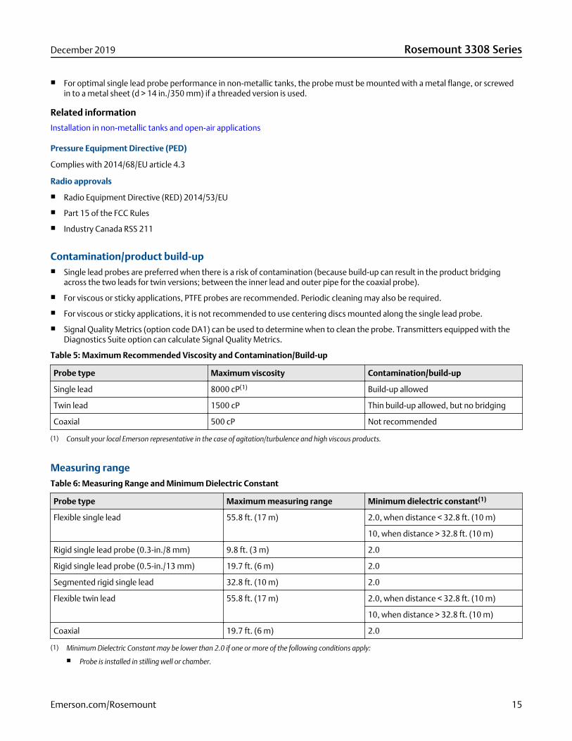
Measuring rangeTable 6: Measuring Range and Minimum Dielectric Constant
Probe type Maximum measuring range Minimum dielectric constant(1)
Flexible single lead 55.8 ft. (17 m) 2.0, when distance < 32.8 ft. (10 m)
10, when distance > 32.8 ft. (10 m)
Rigid single lead probe (0.3-in./8 mm) 9.8 ft. (3 m) 2.0
Rigid single lead probe (0.5-in./13 mm) 19.7 ft. (6 m) 2.0
Segmented rigid single lead 32.8 ft. (10 m) 2.0
Flexible twin lead 55.8 ft. (17 m) 2.0, when distance < 32.8 ft. (10 m)
10, when distance > 32.8 ft. (10 m)
Coaxial 19.7 ft. (6 m) 2.0
(1) Minimum Dielectric Constant may be lower than 2.0 if one or more of the following conditions apply:
■ Probe is installed in stilling well or chamber.
December 2019 Rosemount 3308 Series
Emerson.com/Rosemount 15
■ Maximum measuring range is not utilized.
■ Noise Threshold is manually adjusted to a lower level.
Interface measuring range
The maximum allowable upper product thickness/measuring range is primarily determined by the dielectric constants of the twoliquids.
Typical applications include interfaces between oil/oil-like and water/water-like liquids, with a low (<3) dielectric constant for theupper product and a high (>20) dielectric constant for the lower product. For such applications, the maximum measuring range islimited by the length of the coaxial and rigid single lead probes.
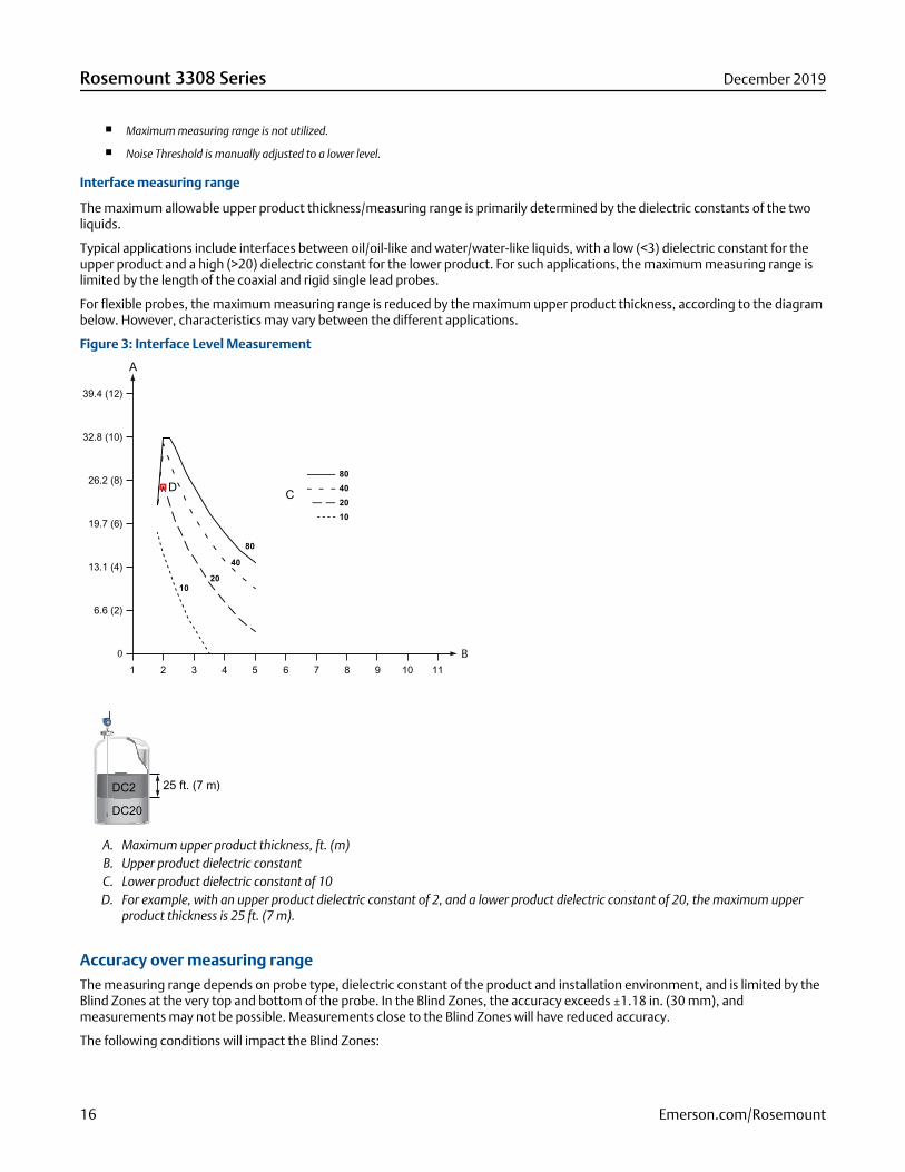
For flexible probes, the maximum measuring range is reduced by the maximum upper product thickness, according to the diagrambelow. However, characteristics may vary between the different applications.
Figure 3: Interface Level Measurement
0
25 ft. (7 m)DC2
DC20
1 2 43 5 6 7 8 9 10 11
6.6 (2)
13.1 (4)
19.7 (6)
26.2 (8)
32.8 (10)
39.4 (12)
D
A
C
B
A. Maximum upper product thickness, ft. (m)B. Upper product dielectric constantC. Lower product dielectric constant of 10D. For example, with an upper product dielectric constant of 2, and a lower product dielectric constant of 20, the maximum upper
product thickness is 25 ft. (7 m).
Accuracy over measuring rangeThe measuring range depends on probe type, dielectric constant of the product and installation environment, and is limited by theBlind Zones at the very top and bottom of the probe. In the Blind Zones, the accuracy exceeds ±1.18 in. (30 mm), andmeasurements may not be possible. Measurements close to the Blind Zones will have reduced accuracy.
The following conditions will impact the Blind Zones:
Rosemount 3308 Series December 2019
16 Emerson.com/Rosemount
■ If the single lead probes or twin probes are installed in a nozzle, the nozzle height shall be added to the specified Upper BlindZone.
■ The measuring range for the PTFE covered flexible single lead probe includes the weight when measuring on a high dielectricmedia.
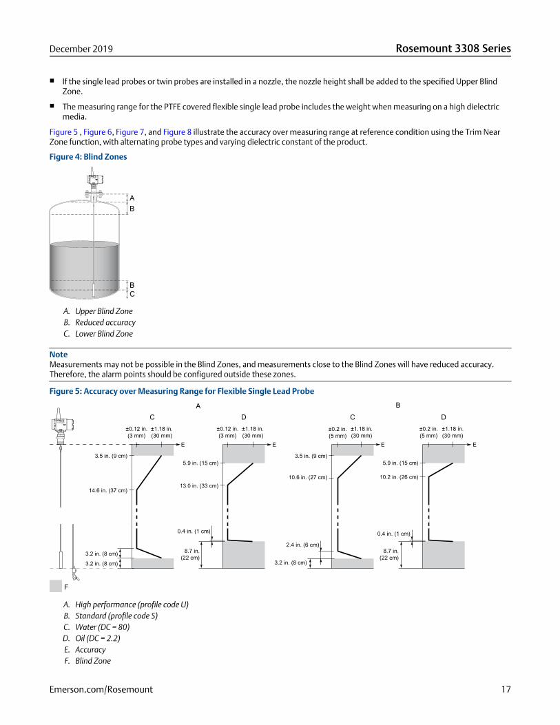
Figure 5 , Figure 6, Figure 7, and Figure 8 illustrate the accuracy over measuring range at reference condition using the Trim NearZone function, with alternating probe types and varying dielectric constant of the product.
Figure 4: Blind Zones
A. Upper Blind ZoneB. Reduced accuracyC. Lower Blind Zone
NoteMeasurements may not be possible in the Blind Zones, and measurements close to the Blind Zones will have reduced accuracy.Therefore, the alarm points should be configured outside these zones.
Figure 5: Accuracy over Measuring Range for Flexible Single Lead Probe
±0.12 in.(3 mm)
±1.18 in.(30 mm)
±0.12 in.(3 mm)
E E E E
±1.18 in.(30 mm)
±0.2 in.(5 mm)
±1.18 in.(30 mm)
±0.2 in.(5 mm)
±1.18 in.(30 mm)
C D C DA B
3.5 in. (9 cm)
14.6 in. (37 cm)13.0 in. (33 cm)
5.9 in. (15 cm) 5.9 in. (15 cm)
0.4 in. (1 cm)
8.7 in. (22 cm)
0.4 in. (1 cm)
8.7 in.(22 cm)
2.4 in. (6 cm)
3.2 in. (8 cm)3.2 in. (8 cm)
3.2 in. (8 cm)
3.5 in. (9 cm)
10.6 in. (27 cm) 10.2 in. (26 cm)
F
A. High performance (profile code U)B. Standard (profile code S)C. Water (DC = 80)D. Oil (DC = 2.2)E. AccuracyF. Blind Zone
December 2019 Rosemount 3308 Series
Emerson.com/Rosemount 17
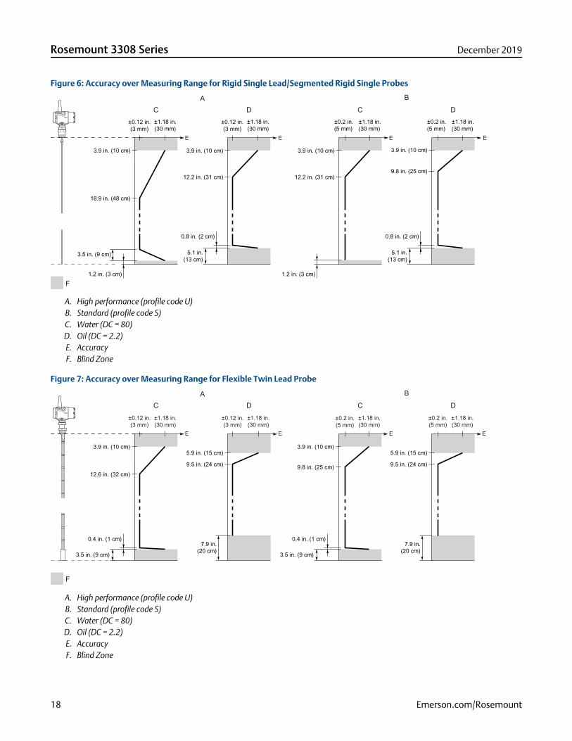
Figure 6: Accuracy over Measuring Range for Rigid Single Lead/Segmented Rigid Single Probes
0.8 in. (2 cm)
5.1 in.(13 cm)
±0.2 in.(5 mm)
3.9 in. (10 cm)3.9 in. (10 cm)
12.2 in. (31 cm)9.8 in. (25 cm)
±0.12 in.(3 mm)
±1.18 in.(30 mm)
±0.12 in.(3 mm)
±1.18 in.(30 mm)
±0.2 in.(5 mm)
±1.18 in.(30 mm)
±1.18 in.(30 mm)
3.5 in. (9 cm)
1.2 in. (3 cm) 1.2 in. (3 cm)
3.9 in. (10 cm)
18.9 in. (48 cm)
3.9 in. (10 cm)
12.2 in. (31 cm)
0.8 in. (2 cm)
5.1 in.(13 cm)
E E E E
C D C DA B
F
A. High performance (profile code U)B. Standard (profile code S)C. Water (DC = 80)D. Oil (DC = 2.2)E. AccuracyF. Blind Zone
Figure 7: Accuracy over Measuring Range for Flexible Twin Lead Probe
0.4 in. (1 cm)
3.5 in. (9 cm)
0.4 in. (1 cm)
3.5 in. (9 cm)
7.9 in.(20 cm)
7.9 in.(20 cm)
5.9 in. (15 cm)
9.5 in. (24 cm)
5.9 in. (15 cm)
9.5 in. (24 cm)
3.9 in. (10 cm)
12.6 in. (32 cm)
3.9 in. (10 cm)
9.8 in. (25 cm)
±0.12 in.(3 mm)
±1.18 in.(30 mm)
±0.12 in.(3 mm)
±1.18 in.(30 mm)
±0.2 in.(5 mm)
±1.18 in.(30 mm)
±0.2 in.(5 mm)
±1.18 in.(30 mm)
E E E E
C D C DA B
F
A. High performance (profile code U)B. Standard (profile code S)C. Water (DC = 80)D. Oil (DC = 2.2)E. AccuracyF. Blind Zone
Rosemount 3308 Series December 2019
18 Emerson.com/Rosemount
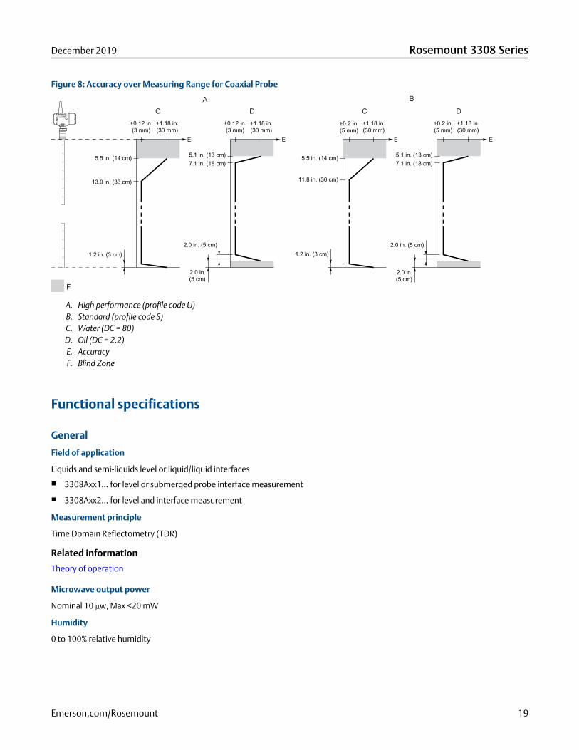
Figure 8: Accuracy over Measuring Range for Coaxial Probe
±0.12 in.(3 mm)
±1.18 in.(30 mm)
±0.12 in.(3 mm)
±1.18 in.(30 mm)
±0.2 in.(5 mm)
±1.18 in.(30 mm)
±0.2 in.(5 mm)
±1.18 in.(30 mm)
5.5 in. (14 cm) 5.5 in. (14 cm)
11.8 in. (30 cm)13.0 in. (33 cm)
5.1 in. (13 cm)7.1 in. (18 cm)
5.1 in. (13 cm)7.1 in. (18 cm)
2.0 in. (5 cm)
2.0 in.(5 cm)
2.0 in. (5 cm)
2.0 in.(5 cm)
1.2 in. (3 cm) 1.2 in. (3 cm)
E E E E
C D C DA B
F
A. High performance (profile code U)B. Standard (profile code S)C. Water (DC = 80)D. Oil (DC = 2.2)E. AccuracyF. Blind Zone
Functional specifications
General
Field of application
Liquids and semi-liquids level or liquid/liquid interfaces
■ 3308Axx1... for level or submerged probe interface measurement
■ 3308Axx2... for level and interface measurement
Measurement principle
Time Domain Reflectometry (TDR)
Related information
Theory of operation
Microwave output power
Nominal 10 µw, Max <20 mW
Humidity
0 to 100% relative humidity
December 2019 Rosemount 3308 Series
Emerson.com/Rosemount 19
Wireless
Output
IEC 62591 (WirelessHART®) 2.4 GHz
Transmit rate
User selectable, 4 seconds to 60 minutes
Frequency range
2400 - 2483.5 MHz
Radio frequency output from antenna
■ External antenna (WK1 option): < 10 mW (+10dBm) EIRP
■ Extended range, external antenna (WM1 option): < 18 mW (12.5dBm) EIRP
■ Remote (WN1 option): < 40mW (16dBm) EIRP
Modulation type
QPSK/iEEE 802.15.4 IEC 62591 (WirelessHART)
Number of channels
15
Channel spacing
5 MHz
Emission designation
G1D
Display and configuration
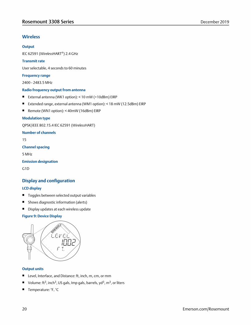
LCD display
■ Toggles between selected output variables
■ Shows diagnostic information (alerts)
■ Display updates at each wireless update
Figure 9: Device Display
Output units
■ Level, Interface, and Distance: ft, inch, m, cm, or mm
■ Volume: ft3, inch3, US gals, Imp gals, barrels, yd3, m3, or liters
■ Temperature: °F, °C
Rosemount 3308 Series December 2019
20 Emerson.com/Rosemount
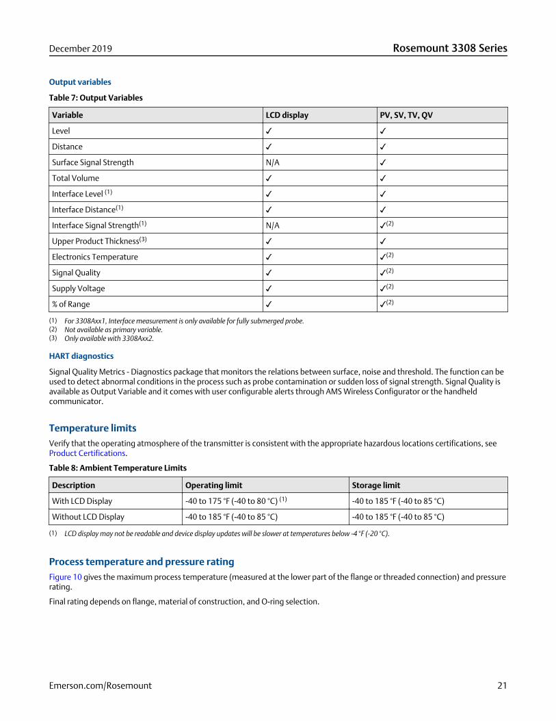
Output variables
Table 7: Output Variables
Variable LCD display PV, SV, TV, QV
Level ✓ ✓
Distance ✓ ✓
Surface Signal Strength N/A ✓
Total Volume ✓ ✓
Interface Level (1) ✓ ✓
Interface Distance(1) ✓ ✓
Interface Signal Strength(1) N/A ✓(2)
Upper Product Thickness(3) ✓ ✓
Electronics Temperature ✓ ✓(2)
Signal Quality ✓ ✓(2)
Supply Voltage ✓ ✓(2)
% of Range ✓ ✓(2)
(1) For 3308Axx1, Interface measurement is only available for fully submerged probe.(2) Not available as primary variable.(3) Only available with 3308Axx2.
HART diagnostics
Signal Quality Metrics - Diagnostics package that monitors the relations between surface, noise and threshold. The function can beused to detect abnormal conditions in the process such as probe contamination or sudden loss of signal strength. Signal Quality isavailable as Output Variable and it comes with user configurable alerts through AMS Wireless Configurator or the handheldcommunicator.
Temperature limitsVerify that the operating atmosphere of the transmitter is consistent with the appropriate hazardous locations certifications, seeProduct Certifications.
Table 8: Ambient Temperature Limits
Description Operating limit Storage limit
With LCD Display -40 to 175 °F (-40 to 80 °C) (1) -40 to 185 °F (-40 to 85 °C)
Without LCD Display -40 to 185 °F (-40 to 85 °C) -40 to 185 °F (-40 to 85 °C)
(1) LCD display may not be readable and device display updates will be slower at temperatures below -4 °F (-20 °C).
Process temperature and pressure ratingFigure 10 gives the maximum process temperature (measured at the lower part of the flange or threaded connection) and pressurerating.
Final rating depends on flange, material of construction, and O-ring selection.
December 2019 Rosemount 3308 Series
Emerson.com/Rosemount 21
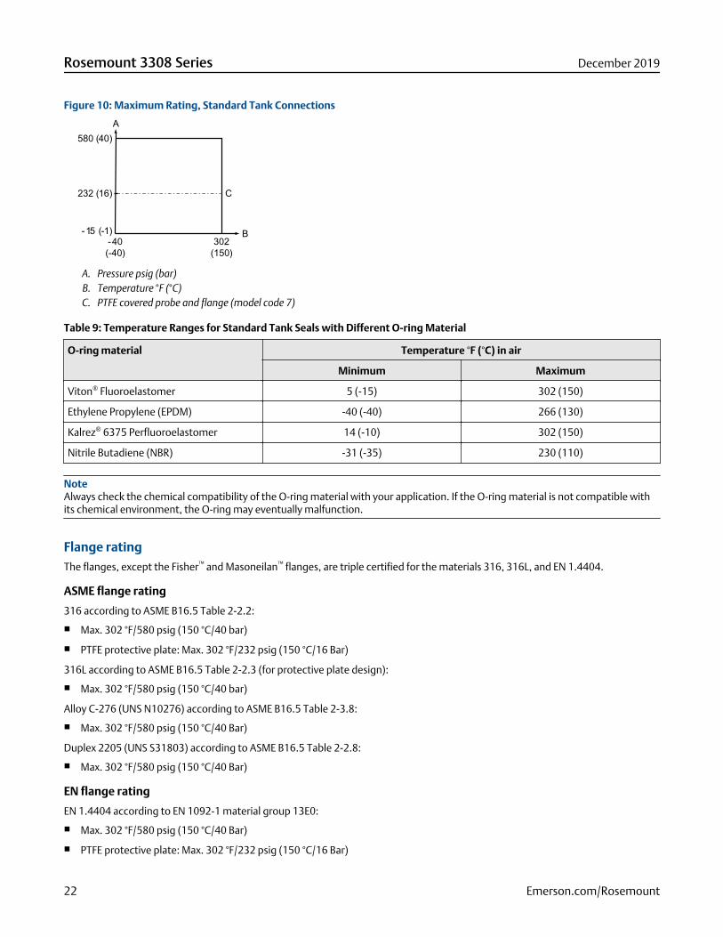
Figure 10: Maximum Rating, Standard Tank Connections
580 (40)
232 (16)
-15 (-1)-40 (-40)
302 (150)
A
C
B
A. Pressure psig (bar)B. Temperature °F (°C)C. PTFE covered probe and flange (model code 7)
Table 9: Temperature Ranges for Standard Tank Seals with Different O-ring Material
O-ring material Temperature °F (°C) in air
Minimum Maximum
Viton® Fluoroelastomer 5 (-15) 302 (150)
Ethylene Propylene (EPDM) -40 (-40) 266 (130)
Kalrez® 6375 Perfluoroelastomer 14 (-10) 302 (150)
Nitrile Butadiene (NBR) -31 (-35) 230 (110)
NoteAlways check the chemical compatibility of the O-ring material with your application. If the O-ring material is not compatible withits chemical environment, the O-ring may eventually malfunction.
Flange ratingThe flanges, except the Fisher™ and Masoneilan™ flanges, are triple certified for the materials 316, 316L, and EN 1.4404.
ASME flange rating
316 according to ASME B16.5 Table 2-2.2:
■ Max. 302 °F/580 psig (150 °C/40 bar)
■ PTFE protective plate: Max. 302 °F/232 psig (150 °C/16 Bar)
316L according to ASME B16.5 Table 2-2.3 (for protective plate design):
■ Max. 302 °F/580 psig (150 °C/40 bar)
Alloy C-276 (UNS N10276) according to ASME B16.5 Table 2-3.8:
■ Max. 302 °F/580 psig (150 °C/40 Bar)
Duplex 2205 (UNS S31803) according to ASME B16.5 Table 2-2.8:
■ Max. 302 °F/580 psig (150 °C/40 Bar)
EN flange rating
EN 1.4404 according to EN 1092-1 material group 13E0:
■ Max. 302 °F/580 psig (150 °C/40 Bar)
■ PTFE protective plate: Max. 302 °F/232 psig (150 °C/16 Bar)
Rosemount 3308 Series December 2019
22 Emerson.com/Rosemount
Alloy C-276 (UNS N10276) according to EN 1092-1 material group 12E0:
■ Max. 302 °F/580 psig (150 °C/40 Bar)
Duplex 2205 (EN 1.4462) according to EN 1092-1 material group 16E0:
■ Max. 580 psig (40 Bar), -22 °F (-30 °C) up to max 302 °F (150 °C)(2)
JIS flange rating
316 according to JIS B2220 material group 2.2:
■ Max. 302 °F/580 psig (150 °C/40 Bar)
■ PTFE protective plate: Max. 302 °F/232 psig (150 °C/16 Bar)
316L according to JIS B2220 material group 2.3 (for protective plate design):
■ Max. 302 °F/580 psig (150 °C/40 Bar)
Fisher and Masoneilan flange rating
316 according to ASME B16.5 Table 2-2.2:
■ Max. 302 °F/580 psig (150 °C/40 Bar)
Tri-Clamp® ratingTable 10: Tri-Clamp Rating
Size Maximum pressure (bar)(1)
1½-in. (37.5 mm) 16
2-in. (50 mm) 16
3-in. (75 mm) 10
4-in. (100 mm) 10
(1) The final rating depends on the clamp and gasket.
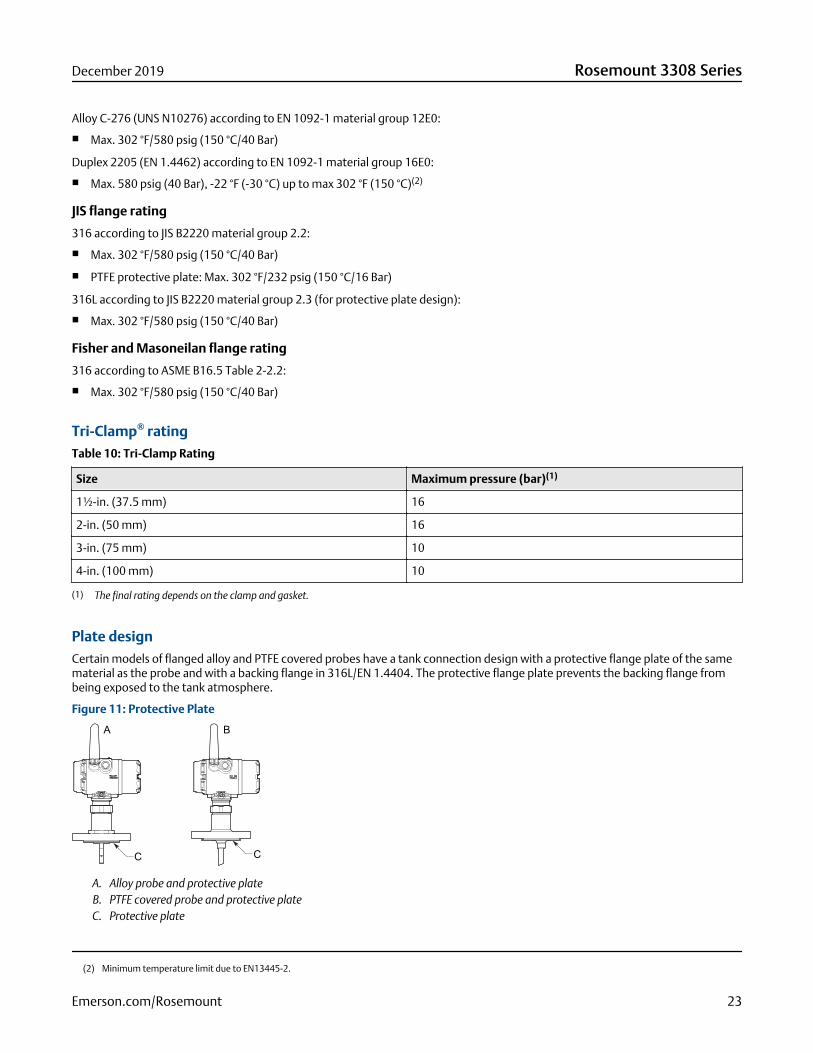
Plate designCertain models of flanged alloy and PTFE covered probes have a tank connection design with a protective flange plate of the samematerial as the probe and with a backing flange in 316L/EN 1.4404. The protective flange plate prevents the backing flange frombeing exposed to the tank atmosphere.
Figure 11: Protective Plate
A. Alloy probe and protective plateB. PTFE covered probe and protective plateC. Protective plate
(2) Minimum temperature limit due to EN13445-2.
December 2019 Rosemount 3308 Series
Emerson.com/Rosemount 23
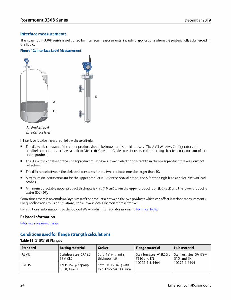
Interface measurementsThe Rosemount 3308 Series is well suited for interface measurements, including applications where the probe is fully submerged inthe liquid.
Figure 12: Interface Level Measurement
A. Product levelB. Interface level
If interface is to be measured, follow these criteria:
■ The dielectric constant of the upper product should be known and should not vary. The AMS Wireless Configurator andhandheld communicator have a built-in Dielectric Constant Guide to assist users in determining the dielectric constant of theupper product.
■ The dielectric constant of the upper product must have a lower dielectric constant than the lower product to have a distinctreflection.
■ The difference between the dielectric constants for the two products must be larger than 10.
■ Maximum dielectric constant for the upper product is 10 for the coaxial probe, and 5 for the single lead and flexible twin leadprobes.
■ Minimum detectable upper product thickness is 4 in. (10 cm) when the upper product is oil (DC=2.2) and the lower product iswater (DC=80).
Sometimes there is an emulsion layer (mix of the products) between the two products which can affect interface measurements.For guidelines on emulsion situations, consult your local Emerson representative.
For additional information, see the Guided Wave Radar Interface Measurement Technical Note.
Related information
Interface measuring range
Conditions used for flange strength calculationsTable 11: 316/316L Flanges
Standard Bolting material Gasket Flange material Hub material
ASME Stainless steel SA193B8M Cl.2
Soft (1a) with min.thickness 1.6 mm
Stainless steel A182 Gr.F316 and EN10222-5-1.4404
Stainless steel SA479M316, and EN10272-1.4404
EN, JIS EN 1515-1/-2 group13E0, A4-70
Soft (EN 1514-1) withmin. thickness 1.6 mm
Rosemount 3308 Series December 2019
24 Emerson.com/Rosemount
Table 12: Process Connection with Plate Design
Standard Bolting material Gasket Flange material Hub material
ASME Stainless steel SA193B8M Cl.2
Soft (1a) with min.thickness 1.6 mm
Stainless steel A182 Gr.F316L/F316 and EN10222-5-1.4404
SB574 Gr. N10276 orSB164 Gr. N04400
EN, JIS EN 1515-1/-2 group13E0, A4-70
Soft (EN 1514-1) withmin. thickness 1.6 mm
Table 13: Alloy C-276 Flanges
Standard Bolting material Gasket Flange material Hub material
ASME UNS N10276 Soft (1a) with min.thickness 1.6 mm
SB462 Gr. N10276(solution annealedcondition) or SB575 Gr.N10276 (solutionannealed condition)
SB574 Gr. N10276
EN, JIS Soft (EN 1514-1) withmin. thickness 1.6 mm
Table 14: Duplex 2205 Flanges
Standard Bolting material Gasket Flange material Hub material
ASME A193 B7 or A320 L7 Soft (1a) with min.thickness 1.6 mm
Duplex stainless steelSA/A182 F51 andEN10222-5-1.4462 orSA/A240 Gr. S31803and EN10028-7-1.4462
Stainless steel SA479MS31803 and EN10272-1.4462
EN, JIS Bumax® 88 Soft (EN 1514-1) withmin. thickness 1.6 mm
Physical specifications
Material selectionEmerson provides a variety of Rosemount products with various product options and configurations including materials ofconstruction that can be expected to perform well in a wide range of applications. The Rosemount product information presentedis intended as a guide for the purchaser to make an appropriate selection for the application. It is the purchaser’s sole responsibilityto make a careful analysis of all process parameters (such as all chemical components, temperature, pressure, flow rate, abrasives,contaminants, etc.), when specifying product, materials, options, and components for the particular application. Emerson is not ina position to evaluate or guarantee the compatibility of the process fluid or other process parameters with the product, options,configuration or materials of construction selected.
Engineered solutionsWhen standard model codes are not sufficient to fulfill requirements, please consult the factory to explore possible EngineeredSolutions. This is typically, but not exclusively, related to the choice of wetted materials or the design of a process connection.These Engineered Solutions are part of the expanded offerings and may be subject to additional delivery lead time. For ordering,factory will supply a special P-labeled numeric option code that should be added at the end of the standard model string.
Housing and enclosure
Ingress protection
IP66/67 and NEMA® 4X
Tank connectionThe tank connection consists of a tank seal, a flange, Tri-Clamp®, or NPT or BSPP (G) threads.
December 2019 Rosemount 3308 Series
Emerson.com/Rosemount 25
Flange dimensionsFollows ASME B16.5, JIS B2220, and EN 1092-1 standards for blind flanges. For Proprietary Fisher™ and Masoneilan™ flanges, seeProprietary flanges.
Probes
Probe versions
Flexible single lead, rigid single lead, segmented rigid single lead, flexible twin lead, and coaxial.
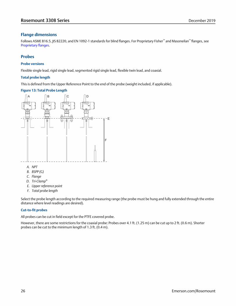
Total probe length
This is defined from the Upper Reference Point to the end of the probe (weight included, if applicable).
Figure 13: Total Probe Length
A. NPTB. BSPP (G)C. FlangeD. Tri-Clamp®
E. Upper reference pointF. Total probe length
Select the probe length according to the required measuring range (the probe must be hung and fully extended through the entiredistance where level readings are desired).
Cut-to-fit probes
All probes can be cut in field except for the PTFE covered probe.
However, there are some restrictions for the coaxial probe: Probes over 4.1 ft. (1.25 m) can be cut up to 2 ft. (0.6 m). Shorterprobes can be cut to the minimum length of 1.3 ft. (0.4 m).
Rosemount 3308 Series December 2019
26 Emerson.com/Rosemount
Minimum and maximum probe length
Probe type Probe length
Flexible single lead 3.3 to 55.8 ft. (1 to 17 m)
Rigid single lead (0.3 in./8 mm) 1.3 to 9.8 ft. (0.4 to 3 m)
Rigid single lead (0.5 in./13 mm) 1.3 to 19.7 ft. (0.4 to 6 m)
Segmented rigid single lead 1.3 to 32.8 ft. (0.4 to 10 m)
Flexible twin lead 3.3 to 55.8 ft. (1 to 17 m)
Coaxial 1.3 to 19.7 ft. (0.4 to 6 m)
Probe angle
0 to 90 degrees from vertical axis
Tensile strength
■ 0.16 in. (4 mm) Flexible single lead SST: 2698 lb (12 kN)
■ 0.16 in. (4 mm) Flexible single lead Alloy C-276: 1798 lb (8 kN)
■ 0.16 in. (4 mm) Flexible single lead Alloy 400: 1124 lb (5 kN)
■ 0.16 in. (4 mm) Flexible single lead Duplex 2205: 1349 lb (6 kN)
■ Flexible twin lead SST: 2023 lb (9 kN)
Collapse load
■ 0.16 in. (4 mm) Flexible single lead SST: 3597 lb (16 kN)
■ 0.16 in. (4 mm) Flexible single lead Alloy C-276: 2023 lb (9 kN)
■ 0.16 in. (4 mm) Flexible single lead Alloy 400: 1349 lb (6 kN)
■ 0.16 in. (4 mm) Flexible single lead Duplex 2205: 1574 lb (7 kN)
Sideway capacity
■ Rigid single lead/Segmented rigid single lead: 4.4 ft. lbf, 0.44 lb at 9.8 ft. (6 Nm, 0.2 kg at 3 m)
■ Coaxial: 73.7 ft. lbf, 3.7 lb at 19.7 ft. (100 Nm, 1.67 kg at 6 m)
Material exposed to tank atmosphereTable 15: Standard Probe (Operating Temperature and Pressure Code S)
Material of construction code Material exposed to tank atmosphere
1 316L (EN 1.4404), 316, PTFE, PFA, silicone grease, and O-ring materials
2 and H Alloy C-276 (UNS N10276), PTFE, PFA, silicone grease, and O-ring materials
3 Alloy 400 (UNS N04400), Alloy K500, PTFE, PFA, silicone grease, and O-ring materials
7 PTFE (1 mm PTFE cover)
8 PTFE, 316/316L (EN 1.4404), silicone grease, and O-ring materials
D Duplex 2205 (UNS S31803/EN 1.4462), Duplex 2507 (UNS S32750/EN 1.4410), PTFE,PFA, silicone grease, and O-ring materials
December 2019 Rosemount 3308 Series
Emerson.com/Rosemount 27
WeightTable 16: Flange and Probes
Item Weight
Flange Depends on flange size
Flexible single lead probe 0.05 lb/ft. (0.08 kg/m)
Rigid single lead probe (0.3-in./8 mm) 0.27 lb/ft. (0.4 kg/m)
Rigid single lead probe (0.5-in./13 mm) 0.71 lb/ft. (1.06 kg/m)
Segmented rigid single lead probe 0.71 lb/ft. (1.06 kg/m)
Flexible twin lead probe 0.09 lb/ft. (0.14 kg/m)
Coaxial probe 0.67 lb/ft. (1 kg/m)
Table 17: End Weight
Item Weight
Small weight (code W1) SST probe: 0.88 lb (0.40 kg)
PTFE covered probe: 2.20 lb (1 kg)
Short weight (code W2) 0.88 lb (0.40 kg)
Heavy weight (code W3) 2.43 lb (1.10 kg)
Weight for twin lead probe 1.3 lb (0.60 kg)
End weight and anchoring optionsThere are in total four weight and anchoring options for flexible single lead probes. See Figure 22 for dimensions.
Small weight (code W1)
A small weight is recommended for narrow tank openings less than 1.5 in. (38 mm). Required weight option for PTFE coveredprobes.
Short weight (code W2)
A short weight is available for the single flexible stainless steel probe. It is recommended for maximized measuring ranges withmeasurements close to the probe end.
Heavy weight (code W3)
A heavy weight is the recommended choice for most applications.
Chuck (code W4)
To tie probe end to tank bottom.
Installation and mounting considerations
Free space requirement
If the probe is mounted close to a wall, nozzle or other tank obstruction, noise might appear in the level signal. Therefore thefollowing minimum clearance, according to Table 18, must be maintained.
Rosemount 3308 Series December 2019
28 Emerson.com/Rosemount
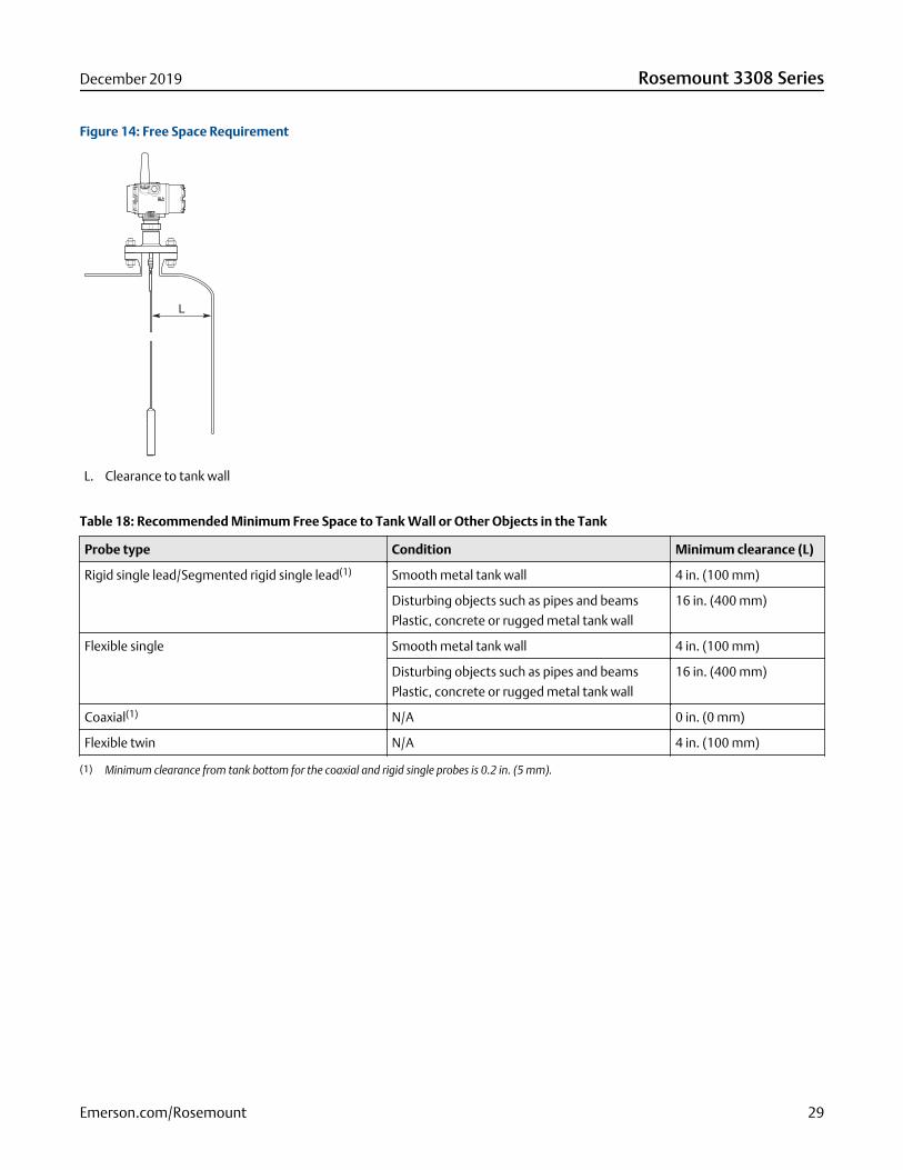
Figure 14: Free Space Requirement
L. Clearance to tank wall
Table 18: Recommended Minimum Free Space to Tank Wall or Other Objects in the Tank
Probe type Condition Minimum clearance (L)
Rigid single lead/Segmented rigid single lead(1) Smooth metal tank wall 4 in. (100 mm)
Disturbing objects such as pipes and beams
Plastic, concrete or rugged metal tank wall
16 in. (400 mm)
Flexible single Smooth metal tank wall 4 in. (100 mm)
Disturbing objects such as pipes and beams
Plastic, concrete or rugged metal tank wall
16 in. (400 mm)
Coaxial(1) N/A 0 in. (0 mm)
Flexible twin N/A 4 in. (100 mm)
(1) Minimum clearance from tank bottom for the coaxial and rigid single probes is 0.2 in. (5 mm).
December 2019 Rosemount 3308 Series
Emerson.com/Rosemount 29
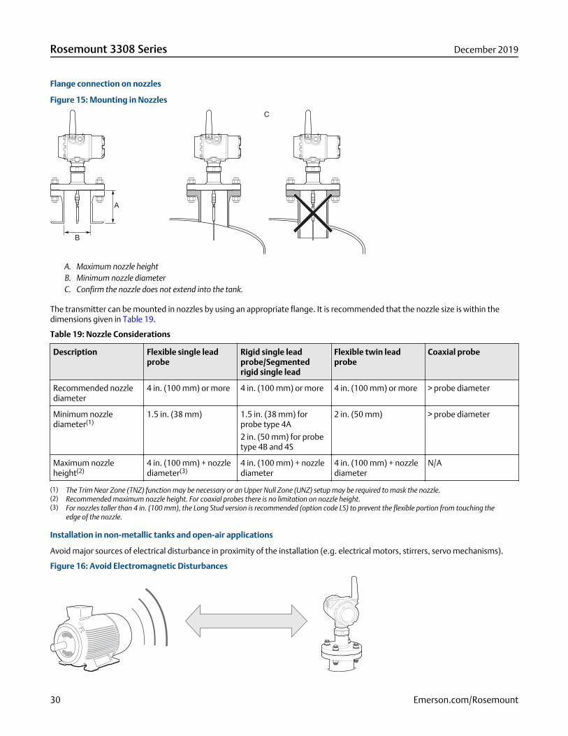
Flange connection on nozzles
Figure 15: Mounting in Nozzles
A. Maximum nozzle heightB. Minimum nozzle diameterC. Confirm the nozzle does not extend into the tank.
The transmitter can be mounted in nozzles by using an appropriate flange. It is recommended that the nozzle size is within thedimensions given in Table 19.
Table 19: Nozzle Considerations
Description Flexible single leadprobe
Rigid single leadprobe/Segmentedrigid single lead
Flexible twin leadprobe
Coaxial probe
Recommended nozzlediameter
4 in. (100 mm) or more 4 in. (100 mm) or more 4 in. (100 mm) or more > probe diameter
Minimum nozzlediameter(1)
1.5 in. (38 mm) 1.5 in. (38 mm) forprobe type 4A
2 in. (50 mm) for probetype 4B and 4S
2 in. (50 mm) > probe diameter
Maximum nozzleheight(2)
4 in. (100 mm) + nozzlediameter(3)
4 in. (100 mm) + nozzlediameter
4 in. (100 mm) + nozzlediameter
N/A
(1) The Trim Near Zone (TNZ) function may be necessary or an Upper Null Zone (UNZ) setup may be required to mask the nozzle.(2) Recommended maximum nozzle height. For coaxial probes there is no limitation on nozzle height.(3) For nozzles taller than 4 in. (100 mm), the Long Stud version is recommended (option code LS) to prevent the flexible portion from touching the
edge of the nozzle.
Installation in non-metallic tanks and open-air applications
Avoid major sources of electrical disturbance in proximity of the installation (e.g. electrical motors, stirrers, servo mechanisms).
Figure 16: Avoid Electromagnetic Disturbances
Rosemount 3308 Series December 2019
30 Emerson.com/Rosemount

For clean liquids, use a coaxial probe to reduce effect of potential electrical disturbances.
Figure 17: Coaxial Probe in an Open-Air Application
For optimal single lead probe performance in non-metallic tanks, the probe must be mounted with a metal flange, or screwed in toa metal sheet (d > 14 in./350 mm) if a threaded version is used.
Figure 18: Mounting in Non-Metallic Tanks
A. Metal flangeB. Metal sheet (d > 14 in./350 mm)
Minimum distance between two single probes
When installing multiple Rosemount 3308A Level Transmitters with single probes in the same tank, ensure to place the devices atproper distance from each other to avoid the risk of interference caused by cross-talk. Table 20 provides recommended minimumdistance between two probes. A coaxial probe or a probe installed in a still pipe will not cause any cross-talk.
Table 20: Minimum Distance between Single Probes
Product Minimum distance between probes
Oil (DC = 2.1) 5.2 ft. (1.6 m)
Water (DC = 80) 3.3 ft. (1.0 m)
Installation in still pipe/chamber
General chamber considerations
Dimensioning the chamber/pipe correctly and selecting the appropriate probe is key to the success in these applications. Whenselecting a smaller chamber/pipe diameter, such as 2-in., a flexible probe is not suitable due to the chance of it coming into contactwith the walls. Also, relatively large side inlets may interfere with the signal.
When gas lift and/or turbulence may occur (e.g. boiling hydrocarbons), a 3- or 4-in. chamber/pipe diameter is recommended formaximum measurement reliability. This is especially true in high pressure and high temperature installations.
December 2019 Rosemount 3308 Series
Emerson.com/Rosemount 31
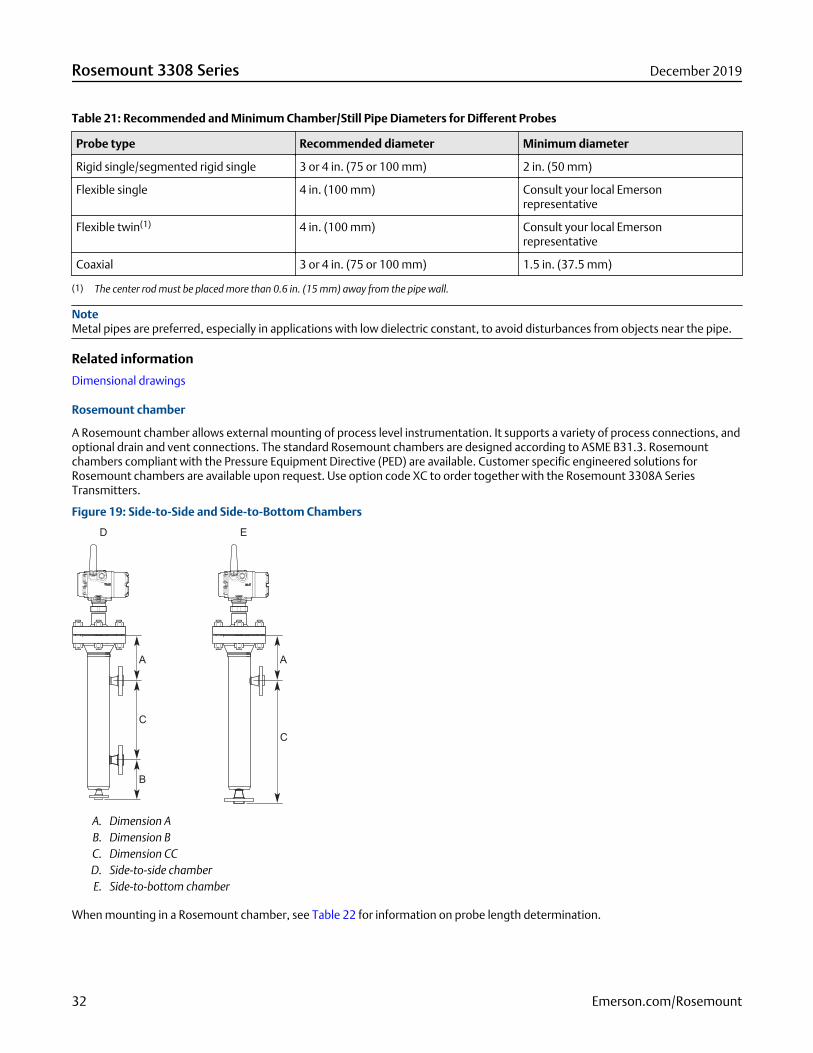
Table 21: Recommended and Minimum Chamber/Still Pipe Diameters for Different Probes
Probe type Recommended diameter Minimum diameter
Rigid single/segmented rigid single 3 or 4 in. (75 or 100 mm) 2 in. (50 mm)
Flexible single 4 in. (100 mm) Consult your local Emersonrepresentative
Flexible twin(1) 4 in. (100 mm) Consult your local Emersonrepresentative
Coaxial 3 or 4 in. (75 or 100 mm) 1.5 in. (37.5 mm)
(1) The center rod must be placed more than 0.6 in. (15 mm) away from the pipe wall.
NoteMetal pipes are preferred, especially in applications with low dielectric constant, to avoid disturbances from objects near the pipe.
Related information
Dimensional drawings
Rosemount chamber
A Rosemount chamber allows external mounting of process level instrumentation. It supports a variety of process connections, andoptional drain and vent connections. The standard Rosemount chambers are designed according to ASME B31.3. Rosemountchambers compliant with the Pressure Equipment Directive (PED) are available. Customer specific engineered solutions forRosemount chambers are available upon request. Use option code XC to order together with the Rosemount 3308A SeriesTransmitters.
Figure 19: Side-to-Side and Side-to-Bottom Chambers
A. Dimension AB. Dimension BC. Dimension CCD. Side-to-side chamberE. Side-to-bottom chamber
When mounting in a Rosemount chamber, see Table 22 for information on probe length determination.
Rosemount 3308 Series December 2019
32 Emerson.com/Rosemount
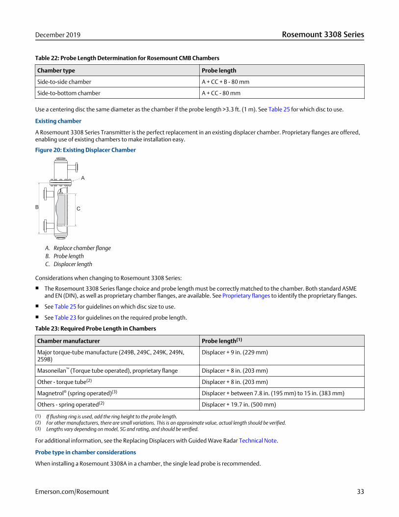
Table 22: Probe Length Determination for Rosemount CMB Chambers
Chamber type Probe length
Side-to-side chamber A + CC + B - 80 mm
Side-to-bottom chamber A + CC - 80 mm
Use a centering disc the same diameter as the chamber if the probe length >3.3 ft. (1 m). See Table 25 for which disc to use.
Existing chamber
A Rosemount 3308 Series Transmitter is the perfect replacement in an existing displacer chamber. Proprietary flanges are offered,enabling use of existing chambers to make installation easy.
Figure 20: Existing Displacer Chamber
A. Replace chamber flangeB. Probe lengthC. Displacer length
Considerations when changing to Rosemount 3308 Series:
■ The Rosemount 3308 Series flange choice and probe length must be correctly matched to the chamber. Both standard ASMEand EN (DIN), as well as proprietary chamber flanges, are available. See Proprietary flanges to identify the proprietary flanges.
■ See Table 25 for guidelines on which disc size to use.
■ See Table 23 for guidelines on the required probe length.
Table 23: Required Probe Length in Chambers
Chamber manufacturer Probe length(1)
Major torque-tube manufacture (249B, 249C, 249K, 249N,259B)
Displacer + 9 in. (229 mm)
Masoneilan™ (Torque tube operated), proprietary flange Displacer + 8 in. (203 mm)
Other - torque tube(2) Displacer + 8 in. (203 mm)
Magnetrol® (spring operated)(3) Displacer + between 7.8 in. (195 mm) to 15 in. (383 mm)
Others - spring operated(2) Displacer + 19.7 in. (500 mm)
(1) If flushing ring is used, add the ring height to the probe length.(2) For other manufacturers, there are small variations. This is an approximate value, actual length should be verified.(3) Lengths vary depending on model, SG and rating, and should be verified.
For additional information, see the Replacing Displacers with Guided Wave Radar Technical Note.
Probe type in chamber considerations
When installing a Rosemount 3308A in a chamber, the single lead probe is recommended.
December 2019 Rosemount 3308 Series
Emerson.com/Rosemount 33
The probe must not touch the chamber wall, should extend the full height of the chamber, but not touch the bottom of thechamber.
The probe length determines if a single rigid or single flexible probe should be used:
■ Less than 19.7 ft. (6.0 m): Rigid single probe is recommended. Use a centering disc for probe > 3.3 ft. (1 m). When mountingspace is limited, use a flexible single probe with a weight and centering disc.
■ More than 19.7 ft. (6.0 m): Use flexible single probe with a weight and centering disc.
PTFE covered probes are not recommended for chamber/pipe installations.
Centering disc for pipe installationsTo prevent the probe from contacting the chamber or pipe wall, centering discs are available for flexible single, rigid single, andflexible twin lead probes. The disc is attached to the end of the probe. Discs are made of stainless steel, Alloy C-276, Duplex 2205,or PTFE.
For the segmented rigid single lead probe, up to five PTFE centering discs can be mounted along the probe, but keep a minimumdistance of two segments between the discs. Additionally, a disc in SST or PTFE (part number 03300-1655-xxxx) can be attached tothe end of the probe.
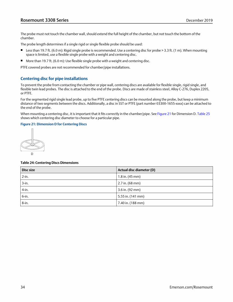
When mounting a centering disc, it is important that it fits correctly in the chamber/pipe. See Figure 21 for Dimension D. Table 25shows which centering disc diameter to choose for a particular pipe.
Figure 21: Dimension D for Centering Discs
Table 24: Centering Discs Dimensions
Disc size Actual disc diameter (D)
2-in. 1.8 in. (45 mm)
3-in. 2.7 in. (68 mm)
4-in. 3.6 in. (92 mm)
6-in. 5.55 in. (141 mm)
8-in. 7.40 in. (188 mm)
Rosemount 3308 Series December 2019
34 Emerson.com/Rosemount
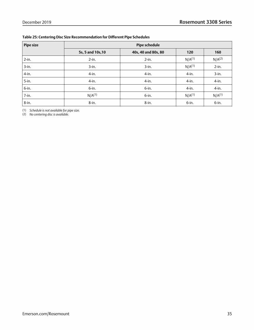
Table 25: Centering Disc Size Recommendation for Different Pipe Schedules
Pipe size Pipe schedule
5s, 5 and 10s,10 40s, 40 and 80s, 80 120 160
2-in. 2-in. 2-in. N/A(1) N/A(2)
3-in. 3-in. 3-in. N/A(1) 2-in.
4-in. 4-in. 4-in. 4-in. 3-in.
5-in. 4-in. 4-in. 4-in. 4-in.
6-in. 6-in. 6-in. 4-in. 4-in.
7-in. N/A(1) 6-in. N/A(1) N/A(1)
8-in. 8-in. 8-in. 6-in. 6-in.
(1) Schedule is not available for pipe size.(2) No centering disc is available.
December 2019 Rosemount 3308 Series
Emerson.com/Rosemount 35
Product CertificationsRev 1.8
European directive informationThe most recent revision of the EU Declaration of Conformity can be found at Emerson.com/Rosemount.
Ordinary location certificationAs standard, the transmitter has been examined and tested to determine that the design meets the basic electrical, mechanical,and fire protection requirements by a nationally recognized test laboratory (NRTL) as accredited by the Federal Occupational Safetyand Health Administration (OSHA).
Telecommunication complianceAll wireless devices require certification to ensure that they adhere to regulations regarding the use of the RF spectrum. Nearlyevery country requires this type of product certification. Emerson is working with governmental agencies around the world tosupply fully compliant products and remove the risk of violating country directives or laws governing wireless device usage.
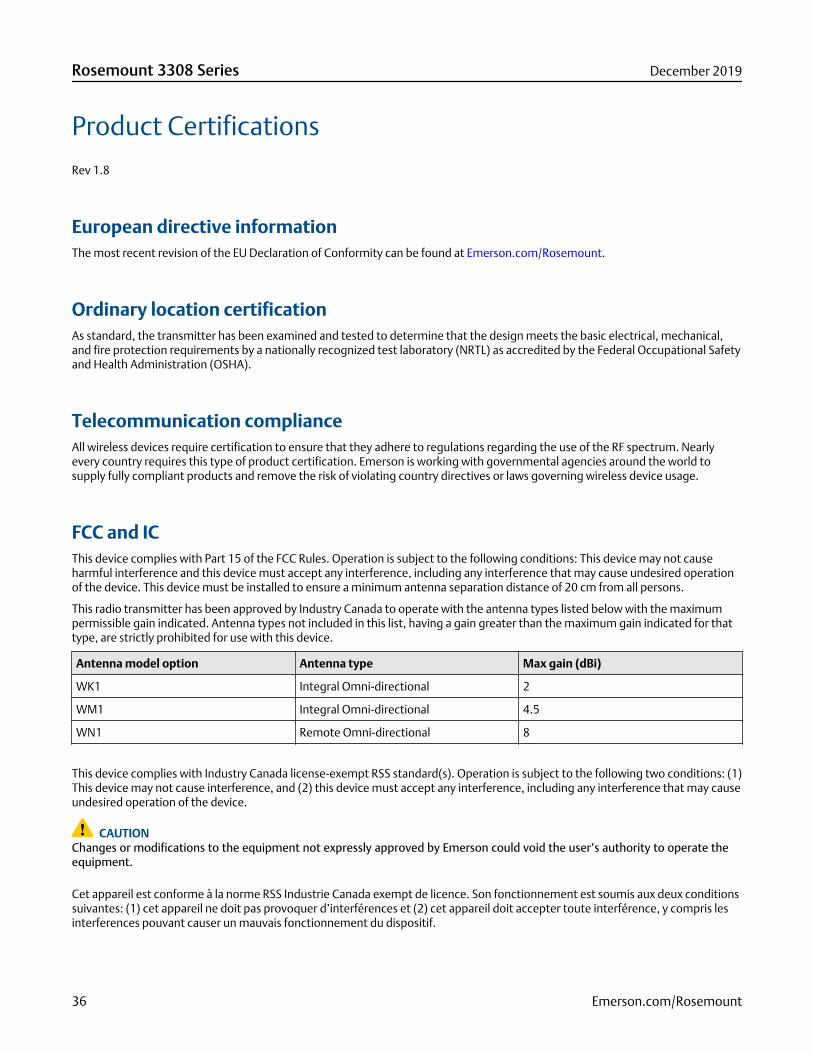
FCC and ICThis device complies with Part 15 of the FCC Rules. Operation is subject to the following conditions: This device may not causeharmful interference and this device must accept any interference, including any interference that may cause undesired operationof the device. This device must be installed to ensure a minimum antenna separation distance of 20 cm from all persons.
This radio transmitter has been approved by Industry Canada to operate with the antenna types listed below with the maximumpermissible gain indicated. Antenna types not included in this list, having a gain greater than the maximum gain indicated for thattype, are strictly prohibited for use with this device.
Antenna model option Antenna type Max gain (dBi)
WK1 Integral Omni-directional 2
WM1 Integral Omni-directional 4.5
WN1 Remote Omni-directional 8
This device complies with Industry Canada license-exempt RSS standard(s). Operation is subject to the following two conditions: (1)This device may not cause interference, and (2) this device must accept any interference, including any interference that may causeundesired operation of the device.
CAUTIONChanges or modifications to the equipment not expressly approved by Emerson could void the user’s authority to operate theequipment.
Cet appareil est conforme à la norme RSS Industrie Canada exempt de licence. Son fonctionnement est soumis aux deux conditionssuivantes: (1) cet appareil ne doit pas provoquer d’interférences et (2) cet appareil doit accepter toute interférence, y compris lesinterferences pouvant causer un mauvais fonctionnement du dispositif.
Rosemount 3308 Series December 2019
36 Emerson.com/Rosemount
CAUTIONLes changements ou les modifications apportés à l'équipement qui n'est pas expressément approuvé par Emerson pourraientannuler l'autorité de l'utilisateur à utiliser cet équipement.
Installing equipment in North AmericaThe US National Electrical Code® (NEC) and the Canadian Electrical Code (CEC) permit the use of Division marked equipment inZones and Zone marked equipment in Divisions. The markings must be suitable for the area classification, gas, and temperatureclass. This information is clearly defined in the respective codes.
USA
I5 US Intrinsic Safety (IS)
Certificate FM17US0014X
Standards FM Class 3600 - 2011, FM Class 3610 - 2015, FM Class 3810 - 2005, ANSI/ISA 60079-0:2013, ANSI/UL60079-11:2014, ANSI/ISA 61010-1:2004, ANSI/NEMA® 250 - 2003, ANSI/IEC 60529:2004
Markings IS CL I, DIV 1, GP A, B, C, D T4; (-55°C ≤ Ta ≤ +70°C)
Class 1, Zone 0 AEx ia IIC T4 Ga; (-55°C ≤ Ta ≤ +70°C)
when installed per Rosemount drawing 03308-1010;
Type 4X; IP66/67
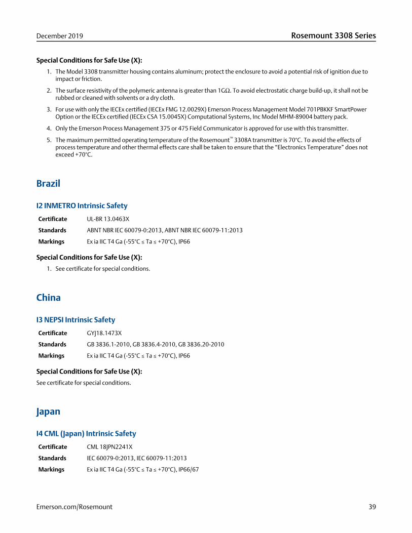
Special Conditions for Safe Use (X):
1. The Model 3308 transmitter housing contains aluminum; protect the enclosure to avoid a potential risk of ignition due toimpact or friction.
2. The surface resistivity of the polymeric antenna is greater than 1GΩ. To avoid electrostatic charge build-up, it shall not berubbed or cleaned with solvents or a dry cloth.
3. For use with only the Emerson Process Management Model 701PBKKF SmartPower™ Option or the Computational Systems,Inc Model MHM-89004 battery module.
4. Only the Emerson Process Management 375 or 475 Field Communicator is approved for use with this transmitter.
5. The maximum permitted operating temperature of the Rosemount™ 3308A transmitter is 70°C. To avoid the effects ofprocess temperature and other thermal effects care shall be taken to ensure that the “Electronics Temperature” does notexceed +70°C.
Canada
I6 Canada Intrinsically Safe
Certificate FM17CA0007X
Standards C22.2 No. 94-M91:1991 (R2011), CAN/CSA C22.2 No. 60079-0:2015, CAN/CSA 22.2 60079-11:2014, C22.2No 61010-1:2004, C22.2 No. 60529:2016
Markings Intrinsically Safe
Class I, Division 1, Groups A, B, C and D T4; (-55°C ≤ Ta ≤ +70°C)
Ex ia IIC Ga T4; (-55°C ≤ Ta ≤ +70°C)
December 2019 Rosemount 3308 Series
Emerson.com/Rosemount 37
when installed per Rosemount drawing 03308-1010;
Type 4X; IP66/67
Special Conditions for Safe Use (X):
1. The Model 3308 transmitter housing contains aluminum; protect the enclosure to avoid a potential risk of ignition due toimpact or friction.
2. The surface resistivity of the polymeric antenna is greater than 1GΩ. To avoid electrostatic charge build-up, it shall not berubbed or cleaned with solvents or a dry cloth.
3. For use with only the Emerson Process Management Model 701PBKKF SmartPower™ Option or the Computational Systems,Inc Model MHM-89004 battery module.
4. Only the Emerson Process Management 375 or 475 Field Communicator is approved for use with this transmitter.
5. The maximum permitted operating temperature of the Rosemount™ 3308A transmitter is 70°C. To avoid the effects ofprocess temperature and other thermal effects care shall be taken to ensure that the “Electronics Temperature” does notexceed +70°C.
Europe
I1 ATEX Intrinsic Safety
Certificate FM 12ATEX0072X
Standards EN 60079-0: 2012 + A11:2013, EN 60079-11: 2012, EN 60529:1991 + A1:2000 + A2:2013
Markings II 1 G Ex ia IIC T4 Ga, (-55°C ≤ Ta ≤ +70°C)
Special Conditions for Safe Use (X):
1. The Model 3308 transmitter housing contains aluminum; protect the enclosure to avoid a potential risk of ignition due toimpact or friction.
2. The surface resistivity of the polymeric antenna is greater than 1GΩ. To avoid electrostatic charge build-up, it shall not berubbed or cleaned with solvents or a dry cloth.
3. For use with only the ATEX certified (Baseefa11ATEX0042X) Emerson Process Management Model 701PBKKF SmartPowerOption or the ATEX certified (Sira 15ATEX2332X) Computational Systems, Inc Model MHM-89004 battery module.
4. Only the ATEX certified (BVS03ATEXE347, BVS09ATEXE023) Emerson Process Management 375 or 475 Field Communicatoris approved for use with this transmitter.
5. The maximum permitted operating temperature of the Rosemount™ 3308A transmitter is 70°C. To avoid the effects ofprocess temperature and other thermal effects care shall be taken to ensure that the “Electronics Temperature” does notexceed +70°C.
International
I7 IECEx Intrinsic Safety
Certificate IECEx FMG 12.0029X
Standards IEC 60079-0: 2011, IEC 60079-11: 2011
Markings Ex ia IIC T4 Ga, (-55°C ≤ Ta ≤ +70°C)
Rosemount 3308 Series December 2019
38 Emerson.com/Rosemount
Special Conditions for Safe Use (X):
1. The Model 3308 transmitter housing contains aluminum; protect the enclosure to avoid a potential risk of ignition due toimpact or friction.
2. The surface resistivity of the polymeric antenna is greater than 1GΩ. To avoid electrostatic charge build-up, it shall not berubbed or cleaned with solvents or a dry cloth.
3. For use with only the IECEx certified (IECEx FMG 12.0029X) Emerson Process Management Model 701PBKKF SmartPowerOption or the IECEx certified (IECEx CSA 15.0045X) Computational Systems, Inc Model MHM-89004 battery pack.
4. Only the Emerson Process Management 375 or 475 Field Communicator is approved for use with this transmitter.
5. The maximum permitted operating temperature of the Rosemount™ 3308A transmitter is 70°C. To avoid the effects ofprocess temperature and other thermal effects care shall be taken to ensure that the “Electronics Temperature” does notexceed +70°C.
Brazil
I2 INMETRO Intrinsic Safety
Certificate UL-BR 13.0463X
Standards ABNT NBR IEC 60079-0:2013, ABNT NBR IEC 60079-11:2013
Markings Ex ia IIC T4 Ga (-55°C ≤ Ta ≤ +70°C), IP66
Special Conditions for Safe Use (X):
1. See certificate for special conditions.
China
I3 NEPSI Intrinsic Safety
Certificate GYJ18.1473X
Standards GB 3836.1-2010, GB 3836.4-2010, GB 3836.20-2010
Markings Ex ia IIC T4 Ga (-55°C ≤ Ta ≤ +70°C), IP66
Special Conditions for Safe Use (X):
See certificate for special conditions.
Japan
I4 CML (Japan) Intrinsic Safety
Certificate CML 18JPN2241X
Standards IEC 60079-0:2013, IEC 60079-11:2013
Markings Ex ia IIC T4 Ga (-55°C ≤ Ta ≤ +70°C), IP66/67
December 2019 Rosemount 3308 Series
Emerson.com/Rosemount 39
Special Conditions for Safe Use (X):
See certificate for special conditions.
Technical Regulations Customs Union (EAC)
IM EAC Intrinsic Safety
Certificate EAЭC RU C-US EX01.B.00041/19
Standards IEC 60079-0:2011, IEC 60079-11:2010
Markings 0Ex ia IIC T4 Ga X, -55°C to +70°C, IP66, IP67
Special Conditions for Safe Use (X):
See certificate for special conditions.
Rosemount 3308 Series December 2019
40 Emerson.com/Rosemount
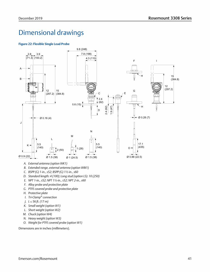
Dimensional drawingsFigure 22: Flexible Single Lead Probe
3.9(100.2)
2.8(71.3)
B
A
J
KO
12(297.2)
15(384.8)
5.5 (140)
Ø 0.9 (22)
L
Ø 0.16 (4) Ø 0.28 (7)
H
2 (50)
Ø 1.5 (38)
N
5.5(140)
Ø 1.5 (38)
M
Ø 1 (24.5)
E
2.4
(62)
1.9
(47)
17.1(435)
Ø 0.88 (22.5)
G
I
H
F
12(297.2)
0.6 (15)
7.8 (198)
9.8 (248)
4.3 (110)
C
2.4(62)
D
1 (26)
15(384.8)
A. External antenna (option WK1)B. Extended range, external antenna (option WM1)C. BSPP (G) 1-in., s52; BSPP (G) 1½-in., s60D. Standard length: 4 (100); Long stud (option LS): 10 (250)E. NPT 1-in., s52; NPT 1½-in., s52; NPT 2-in., s60F. Alloy probe and protective plate
G. PTFE covered probe and protective plateH. Protective plate
I. Tri-Clamp® connectionJ. L ≤ 56 ft. (17 m)
K. Small weight (option W1)L. Short weight (option W2)
M. Chuck (option W4)N. Heavy weight (option W3)O. Weight for PTFE covered probe (option W1)
Dimensions are in inches (millimeters).
December 2019 Rosemount 3308 Series
Emerson.com/Rosemount 41
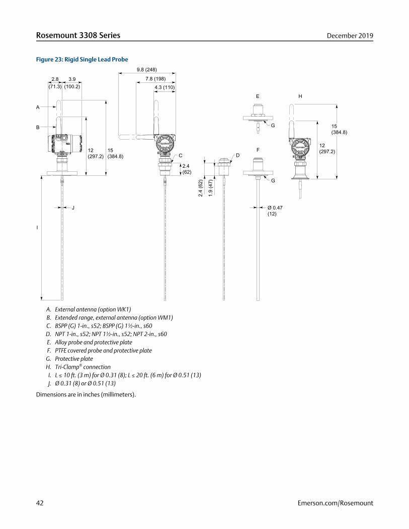
Figure 23: Rigid Single Lead Probe
I
G
D
2.4
(62)
1.9
(47)
E
G
F
3.9(100.2)
2.8(71.3)
B
A
12(297.2)
15(384.8)
J Ø 0.47(12)
C
2.4(62)
7.8 (198)
9.8 (248)
4.3 (110)
12(297.2)
H
15(384.8)
A. External antenna (option WK1)B. Extended range, external antenna (option WM1)C. BSPP (G) 1-in., s52; BSPP (G) 1½-in., s60D. NPT 1-in., s52; NPT 1½-in., s52; NPT 2-in., s60E. Alloy probe and protective plateF. PTFE covered probe and protective plate
G. Protective plateH. Tri-Clamp® connection
I. L ≤ 10 ft. (3 m) for Ø 0.31 (8); L ≤ 20 ft. (6 m) for Ø 0.51 (13)J. Ø 0.31 (8) or Ø 0.51 (13)
Dimensions are in inches (millimeters).
Rosemount 3308 Series December 2019
42 Emerson.com/Rosemount
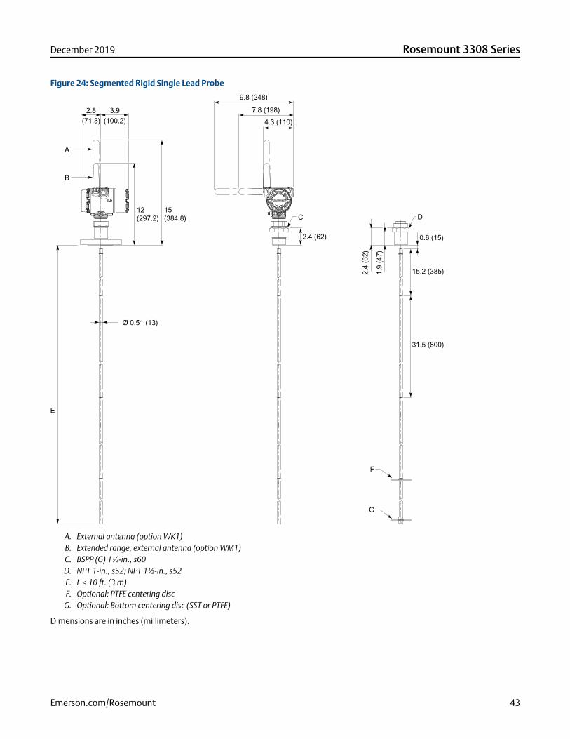
Figure 24: Segmented Rigid Single Lead Probe
F
G
0.6 (15)
15.2 (385)
31.5 (800)
Ø 0.51 (13)
E
D
2.4
(62)
1.9
(47)
C
2.4 (62)
3.9(100.2)
2.8(71.3)
B
A
12(297.2)
15(384.8)
7.8 (198)
9.8 (248)
4.3 (110)
A. External antenna (option WK1)B. Extended range, external antenna (option WM1)C. BSPP (G) 1½-in., s60D. NPT 1-in., s52; NPT 1½-in., s52E. L ≤ 10 ft. (3 m)F. Optional: PTFE centering disc
G. Optional: Bottom centering disc (SST or PTFE)
Dimensions are in inches (millimeters).
December 2019 Rosemount 3308 Series
Emerson.com/Rosemount 43
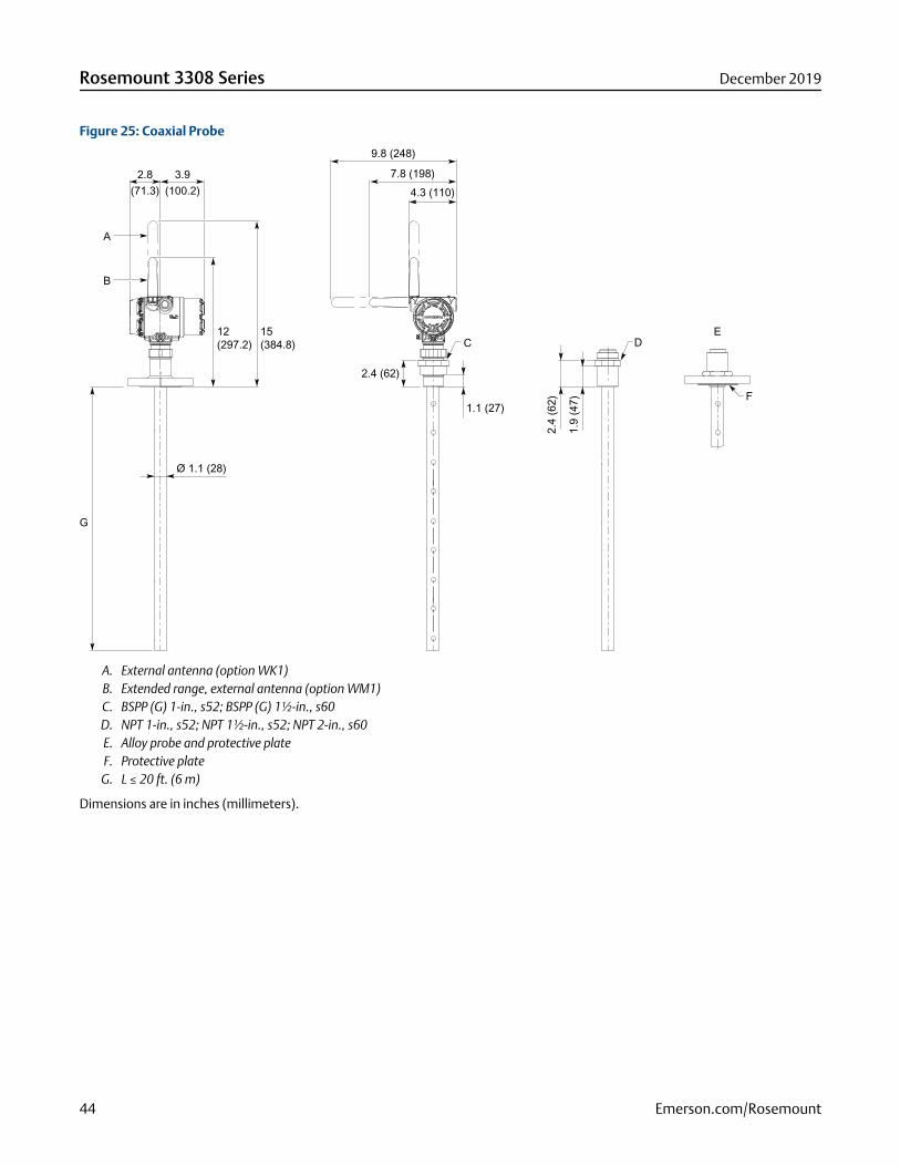
Figure 25: Coaxial Probe
2.4 (62)
1.1 (27)
Ø 1.1 (28)
F
E
G
D
2.4
(62)
1.9
(47)
C
3.9(100.2)
2.8(71.3)
B
A
12(297.2)
15(384.8)
7.8 (198)
9.8 (248)
4.3 (110)
A. External antenna (option WK1)B. Extended range, external antenna (option WM1)C. BSPP (G) 1-in., s52; BSPP (G) 1½-in., s60D. NPT 1-in., s52; NPT 1½-in., s52; NPT 2-in., s60E. Alloy probe and protective plateF. Protective plate
G. L ≤ 20 ft. (6 m)
Dimensions are in inches (millimeters).
Rosemount 3308 Series December 2019
44 Emerson.com/Rosemount
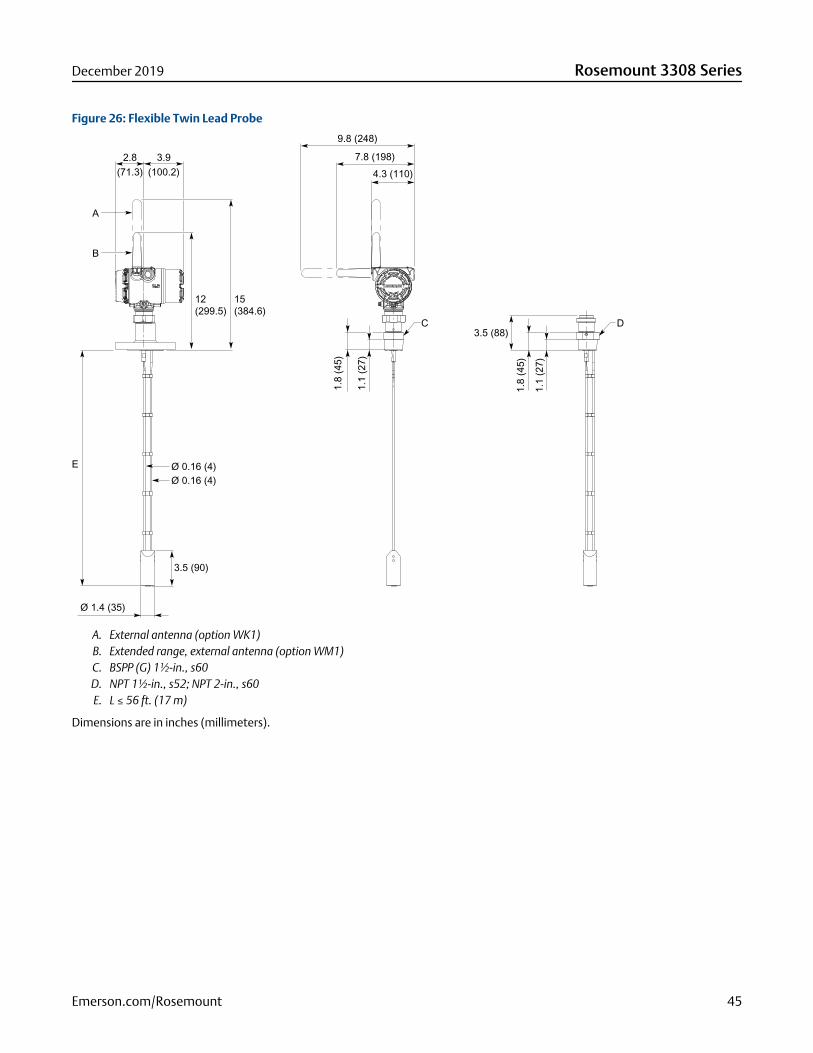
Figure 26: Flexible Twin Lead Probe
3.5 (88)
Ø 0.16 (4)Ø 0.16 (4)
1.8
(45)
1.1
(27)
Ø 1.4 (35)
3.5 (90)
E
C D1.
8 (4
5)
1.1
(27)
3.9(100.2)
2.8(71.3)
B
A
12(299.5)
15(384.6)
7.8 (198)
9.8 (248)
4.3 (110)
A. External antenna (option WK1)B. Extended range, external antenna (option WM1)C. BSPP (G) 1½-in., s60D. NPT 1½-in., s52; NPT 2-in., s60E. L ≤ 56 ft. (17 m)
Dimensions are in inches (millimeters).
December 2019 Rosemount 3308 Series
Emerson.com/Rosemount 45
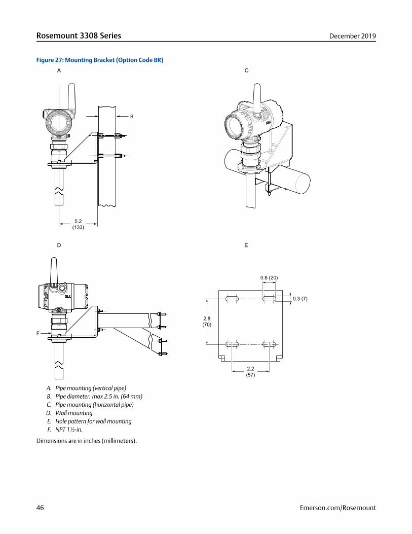
Figure 27: Mounting Bracket (Option Code BR)
2.2(57)
0.3 (7)
0.8 (20)
2.8(70)
5.2(133)
F
B
A
D E
C
A. Pipe mounting (vertical pipe)B. Pipe diameter, max 2.5 in. (64 mm)C. Pipe mounting (horizontal pipe)D. Wall mountingE. Hole pattern for wall mountingF. NPT 1½-in.
Dimensions are in inches (millimeters).
Rosemount 3308 Series December 2019
46 Emerson.com/Rosemount
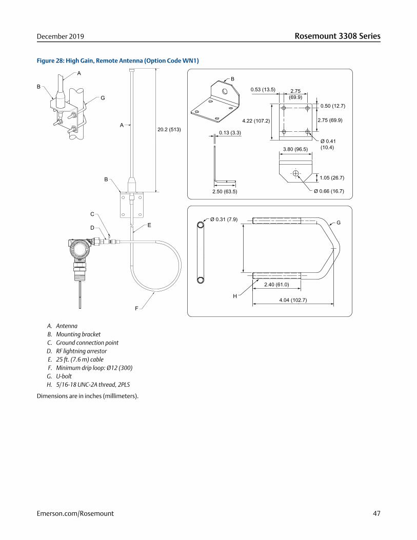
Figure 28: High Gain, Remote Antenna (Option Code WN1)
IN E
XPLOSIVE ATMOSPHERE
KEEP TIGHT WHEN CIRCUIT A
LIVE
A
B
B
G
B
C
F
D
20.2 (513)
E
H
Ø 0.31 (7.9)
0.13 (3.3)
1.05 (26.7)
Ø 0.66 (16.7)
Ø 0.41 (10.4)
2.75 (69.9)4.22 (107.2)
0.53 (13.5) 2.75 (69.9)
0.50 (12.7)
3.80 (96.5)
2.40 (61.0)
4.04 (102.7)
G
A
2.50 (63.5)
A. AntennaB. Mounting bracketC. Ground connection pointD. RF lightning arrestorE. 25 ft. (7.6 m) cableF. Minimum drip loop: Ø12 (300)
G. U-boltH. 5/16-18 UNC-2A thread, 2PLS
Dimensions are in inches (millimeters).
December 2019 Rosemount 3308 Series
Emerson.com/Rosemount 47
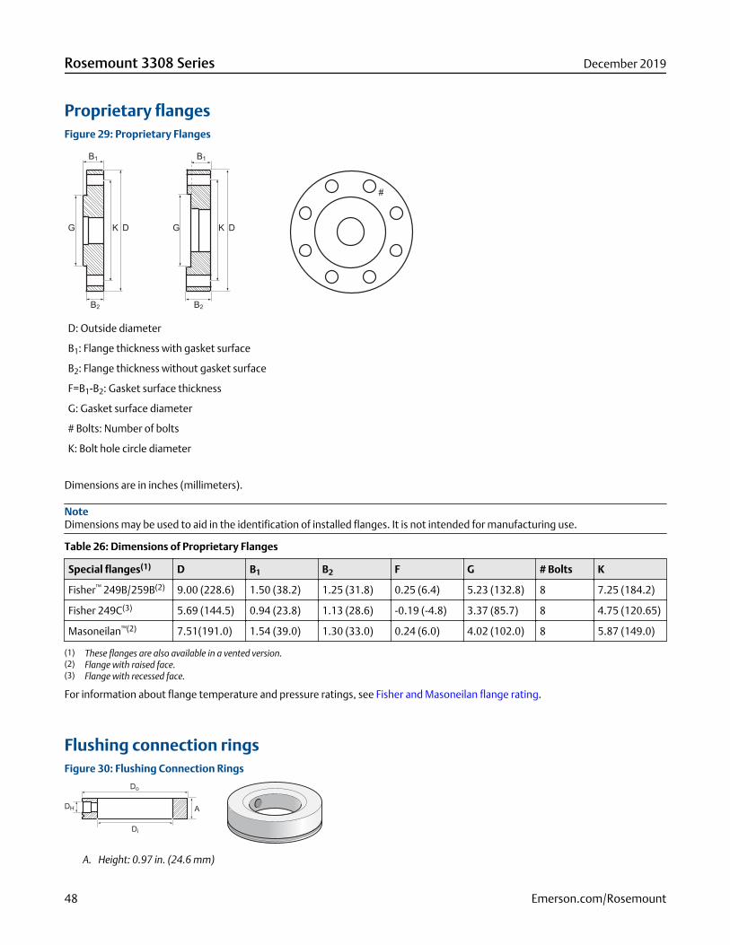
Proprietary flangesFigure 29: Proprietary Flanges
D: Outside diameter
B1: Flange thickness with gasket surface
B2: Flange thickness without gasket surface
F=B1-B2: Gasket surface thickness
G: Gasket surface diameter
# Bolts: Number of bolts
K: Bolt hole circle diameter
Dimensions are in inches (millimeters).
NoteDimensions may be used to aid in the identification of installed flanges. It is not intended for manufacturing use.
Table 26: Dimensions of Proprietary Flanges
Special flanges(1) D B1 B2 F G # Bolts K
Fisher™ 249B/259B(2) 9.00 (228.6) 1.50 (38.2) 1.25 (31.8) 0.25 (6.4) 5.23 (132.8) 8 7.25 (184.2)
Fisher 249C(3) 5.69 (144.5) 0.94 (23.8) 1.13 (28.6) -0.19 (-4.8) 3.37 (85.7) 8 4.75 (120.65)
Masoneilan™(2) 7.51(191.0) 1.54 (39.0) 1.30 (33.0) 0.24 (6.0) 4.02 (102.0) 8 5.87 (149.0)
(1) These flanges are also available in a vented version.(2) Flange with raised face.(3) Flange with recessed face.
For information about flange temperature and pressure ratings, see Fisher and Masoneilan flange rating.
Flushing connection ringsFigure 30: Flushing Connection Rings
A. Height: 0.97 in. (24.6 mm)
Rosemount 3308 Series December 2019
48 Emerson.com/Rosemount
Table 27: Pressure and Temperature Rating for Flushing Ring up to Class 2500
Flushing connection rings Di Do DH
2 in. ANSI 2.12 (53.8) 3.62 (91.9) ¼ in. NPT
3 in. ANSI 3.60 (91.4) 5.00 (127.0) ¼ in. NPT
4 in. ANSI/DN100 3.60 (91.4) 6.20 (157.5) ¼ in. NPT
DN50 2.40 (61.0) 4.00 (102.0) ¼ in. NPT
DN80 3.60 (91.4) 5.43 (138.0) ¼ in. NPT
December 2019 Rosemount 3308 Series
Emerson.com/Rosemount 49
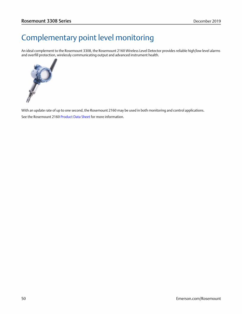
Complementary point level monitoringAn ideal complement to the Rosemount 3308, the Rosemount 2160 Wireless Level Detector provides reliable high/low level alarmsand overfill protection, wirelessly communicating output and advanced instrument health.
With an update rate of up to one second, the Rosemount 2160 may be used in both monitoring and control applications.
See the Rosemount 2160 Product Data Sheet for more information.
Rosemount 3308 Series December 2019
50 Emerson.com/Rosemount

December 2019 Rosemount 3308 Series
Emerson.com/Rosemount 51

00813-0100-4308Rev. DD
December 2019
Global HeadquartersEmerson Automation Solutions6021 Innovation Blvd.Shakopee, MN 55379, USA
+1 800 999 9307 or +1 952 906 8888
+1 952 204 8889
North America Regional OfficeEmerson Automation Solutions8200 Market Blvd.Chanhassen, MN 55317, USA
+1 800 999 9307 or +1 952 906 8888
+1 952 204 8889
Latin America Regional OfficeEmerson Automation Solutions1300 Concord Terrace, Suite 400Sunrise, FL 33323, USA
+1 954 846 5030
+1 954 846 5121
Europe Regional OfficeEmerson Automation Solutions EuropeGmbHNeuhofstrasse 19a P.O. Box 1046CH 6340 BaarSwitzerland
+41 (0) 41 768 6111
+41 (0) 41 768 6300
Asia Pacific Regional OfficeEmerson Automation Solutions1 Pandan CrescentSingapore 128461
+65 6777 8211
+65 6777 0947
Middle East and Africa Regional OfficeEmerson Automation SolutionsEmerson FZE P.O. Box 17033Jebel Ali Free Zone - South 2Dubai, United Arab Emirates
+971 4 8118100
+971 4 8865465
Linkedin.com/company/Emerson-Automation-Solutions
Twitter.com/Rosemount_News
Facebook.com/Rosemount
Youtube.com/user/RosemountMeasurement
©2019 Emerson. All rights reserved.
Emerson Terms and Conditions of Sale are available upon request. The Emerson logo is atrademark and service mark of Emerson Electric Co. Rosemount is a mark of one of theEmerson family of companies. All other marks are the property of their respective owners.