Embed Size (px)
Citation preview
© 2020 Irizar Heavy Industries Inc. All rights reserved
Exceeding International Standards since 1999 ` 1 | P a g e
IRIZAR HEAVY INDUSTRIES INC Head Office: 1512 Adamson View, Edmonton, Alberta T6W 0V4, Canada
Factory: 464014 RR 235, County of Wetaskiwin, AB, T0C 1Z0, Canada Phone: 1 780 450 6695, Fax: 1 780 485 6677
Email: [email protected] Website: www.jirizar.com
PRODUCT CATALOG 2020
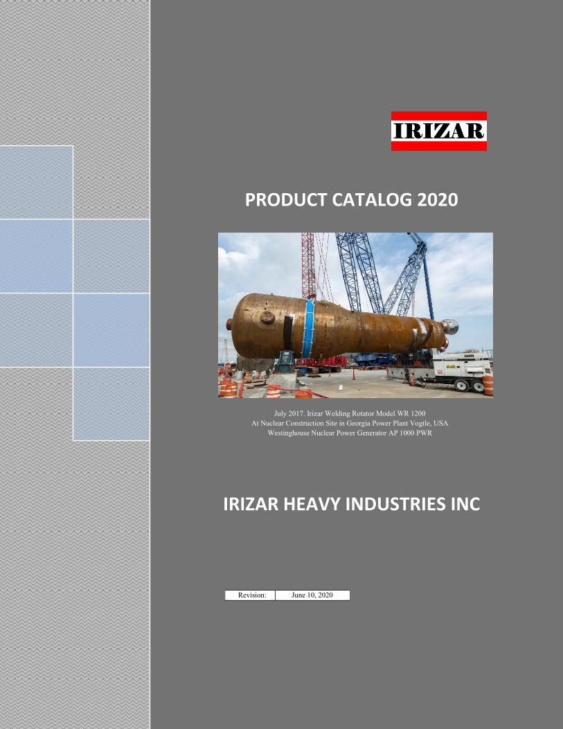
July 2017. Irizar Welding Rotator Model WR 1200
At Nuclear Construction Site in Georgia Power Plant Vogtle, USA
Westinghouse Nuclear Power Generator AP 1000 PWR
IRIZAR HEAVY INDUSTRIES INC
Revision: June 10, 2020

Product Catalog 2020
© 2020 Irizar Heavy Industries Inc. All rights reserved
Exceeding International Standards since 1999 ` 2 | P a g e
IRIZAR HEAVY INDUSTRIES INC Head Office: 1512 Adamson View, Edmonton, Alberta T6W 0V4, Canada Factory: 464014 RR 235, County of Wetaskiwin, AB, T0C 1Z0, Canada
Phone: 1 780 450 6695, Fax: 1 780 485 6677 Email: [email protected] Website: www.jirizar.com
PRODUCT RANGE
1. Conventional Welding Rotators: From 1 to 2,000 MT
2. Anti-Drift (Anti-Creep) Turning Rolls: From 250 to 3,000 MT
3. Self Aligned Rotators: From 5 to 500 MT
4. Chain Welding Rotators: 20 MT
5. Pipe Rotators: From 1 to 25 MT
6. Welding Positioners: From 0.3 to 100 MT
7. Head & Tail Stock: From 1 to 100 MT
8. Welding Manipulators: From 2 x 2 m to 8 x 6 m (vertical x horizontal)
9. Girth Welders: AGW-1, AGW-1-C, AGW-2, LNG AGW-1 & Motorized Baskets
10. Tank Lifting Jacks: Up to 3,000 MT tank weightlifting capacity. Jacks with load capacity
of 12 MT & 25 MT. Applicable on Field Erected Tanks API-650, LNG API 620 Welded
Tanks, Grain Bins, and Smooth Wall Bolted Tanks.
Irizar Heavy Industries Inc is proudly a
Canadian Company with headquarters in
Edmonton, Canada.
INDUSTRIAL SEGMENT
Our products have been used among other
industries: Oil & Gas, Power Generation,
Nuclear, Aerospace, Pipes and Pressure
Vessels, Onshore & Offshore Wind
Towers and Monopiles, Rail Tanks,
Defense Industry, Mining, and Food
Industry.
DESIGN: Our products are Designed & Engineered in Canada; and, made by our own Factory in China. We are proud to own The World Largest
Stock of Welding Positioning Equipment and Tank Lifting Jacks. Our warehouse it’s located in Wetaskiwin Alberta Canada in a thirty acres lot;
at thirty-five minutes from Edmonton International Airport. Welcome to visit our Show Room.
STOCK & DELIVERY: We are proud to have The World Largest Stock of Welding Positioning Equipment and Tank Lifting Jacks. Available a
multi-million-dollar stock; around, 95% of the products on this brochure. It means, over 3,000 units, and 25,000 spare parts. Our delivery in
Canada is 3 to 5 days; in USA & US-Mexican border, one week; in Latino America approx. 4 weeks; World-Wide around 5 to 6 weeks
EXPORTATION: We have exported over sixty countries, among them: Angola, Argentina, Australia, Belgium, Bahamas, Bolivia, Brazil, Canada,
Chad, Chile, China, Colombia, Costa Rica, Cote D’ Ivoire, Denmark, Ecuador, Egypt, France, Germany, Greece, Guatemala, India, Indonesia,
Ireland, Italy, Japan, Jordan, Kazakhstan, Kuwait, Madagascar, Martinique & Guadeloupe, Mexico, Morocco, Netherlands, New Zealand, Nigeria,
Norway, Oman, Pakistan, Panama, Paraguay, Peru, Philippines, Poland, Romania, Russia Federation, Saudi Arabia, Singapore, Serbia, South
Africa, Spain, Tanzania, Taiwan (China), Thailand, Ukraine, United Arab Emirates, United Kingdom, Uruguay, USA and Venezuela.
OUR GOALS: To Build State of art High-Tech Products; to Exceed International-Standards; to provide Top-Quality and Safety Products; to
provide First-Class Service; to offer the Most Competitive-Price; to Deliver within the Shortest-Time; and to Build a Long-Term Business
Relationship with our customers. Our company produces finished products; but there is more to it. Passionate employees in every department
which captivate what we stand for, to great ideas and true commitment; to do our best. Research & Development: Everything start from the
research for the perfect materials tested by extensive and rigorous testing methods. With our state-of-the-art testing and measurement equipment,
we regularly rise the bar again and again. Our design engineers only aim for the best. Production and Logistics: Quality comes first. With constant
quality control immersed within the production process, we guaranty prestige products for our clients. Each product is pack and ship in premium
packaging. Sales & Marketing: Our multinational team covers more than fifty countries all over the World. Technical Support: Our trust, know
how, integrity, as well as, our fast and flexible service is always appreciated.
Page CONTENTS
Anti-Drift Welding Rotator Model WR 3000
3000 MT (6,600,000 #) load and rotation capacity
3 Conventional Tank Turning Rolls WR Series
5 Anti-Drift Turning Rolls AD-WR Series
6 Self-Aligned Tank Turning Rolls SAR Series
9 Chain Welding Rotators & Custom Built
10 Fit Up Rolls Growing Line
11 Pipe Rotators PR & PP Series
12 Welding Positioners WP Series
14 Welding Positioners CWP Series
15 Welding Positioners PL Series
15 Head & Tail Stock HT Series
15 Turn-Tables TT Series
16 Welding Manipulators WM Series Notes: The information contained on this brochure is intended to
be accurate. However, the manufacturer reserves the right to
make changes in design which may not be included
Limited Warranty
Terms and Conditions of Sale
18 Automatic Girth Welders AGW Series
21 Linear Oscillator Welding Tractor
22 Irizar Magnetic Device
22 Tank Jacking System

Product Catalog 2020
© 2020 Irizar Heavy Industries Inc. All rights reserved
Exceeding International Standards since 1999 ` 3 | P a g e
IRIZAR HEAVY INDUSTRIES INC Head Office: 1512 Adamson View, Edmonton, Alberta T6W 0V4, Canada Factory: 464014 RR 235, County of Wetaskiwin, AB, T0C 1Z0, Canada
Phone: 1 780 450 6695, Fax: 1 780 485 6677 Email: [email protected] Website: www.jirizar.com
Conventional Tank Turning Rolls, WR Series Conventional Welding Rotators, also known as: Tank Rollers, Welding Rollers, Tank Rotators, Weld Rotators, Pipe
Rotators, Welding Rolls, Welding Rotators, Vessel Rollers, Tank Rolls and Turning Rolls
Model
Load &
Rotation
Capacity
(MT)
Rotation
speed
(mm/min)
Power
(kW)
Torque
(Nm)
Vessel
Diameter
Range
(mm)
Wheel
(mm)
Dimensions
L*W*H (mm) Weight
(MT) Diam Width Power Roll Idler Roll
WR 3 3 100-1000 2*0.25 1200 150-2500 200 112 1900*500*450 1350*300*450 0.35
WR 5 5 100-1000 2*0.37 2200 150-3200 250 140 2000*500*480 1600*380*480 0.80
WR 10 10 100-1000 2*0.55 4000 250-4800 300 170 2440*610*550 2320*450*550 1.00
WR 20 20 100-1000 2*1.10 9250 250-4800 350 180 3000*675*600 2500*500*600 1.50
WR 40 40 100-1000 2*1.50 14400 250-4800 400 200 3100*700*650 2610*700*650 2.30
WR 60 60 100-1000 2*2.20 23750 300-5200 450 220 3450*820*830 3000*820*830 2.40
WR 80 80 100-1000 2*3.00 26400 300-5200 500 240 4380*900*890 3400*700*890 2.90
WR 100 100 100-1000 2*3.00 36000 350-7800 500 260 4380*970*980 3800*760*980 4.80
WR 150 150 100-1000 2*4.00 48000 350-7800 500 260 4210*1000*980 3800*800*980 5.50
WR 250 250 100-1000 2*5.50 87000 550-9000 660 260 4900*1060*1100 4380*920*1100 10.00
WR 400 400 100-1000 2*5.50 92000 550-9000 700 300 5900*1140*1180 5500*920*1180 17.50
WR 600 600 100-1000 2*7.50 162000 550-9000 900 360 6900*1300*1600 6000*1200*1600 27.50
WR 800 800 100-1000 2*11.0 237000 550-9000 900 380 7100*1400*1600 6500*1260*1600 35
WR 1000 1000 100-1000 2*11.0 360000 1100-12000 1000 400 7500*1600*1700 7000*1320*1700 40.
WR 1200 1200 100-1000 2*11.0 360000 1100-12000 1000 450 8500*1600*1800 7500*1320*1800 48
WR 1600 1600 100-1000 2*18.5 NA 1100-12000 1200 600 8500*2320*2800 11000*2028*2800 110
WR 2000 2000 100-1000 2*25.9 NA 1100-12000 1200 600 8500*2320*2800 11000*2028*2800 140
3D: WR 3 - WR 400 3D: WR 600 - WR 1200 Photos/Video
Features
1. Engineered in Canada; made in China
2. Prototype static and dynamic tested at full capacity by Canadian Testing Laboratory
3. Rotators wheels from Model WR 3 to WR 100 are made of Cast Iron; covered with
heavy duty rubber HSA80, and two steel rings at the side. Rotators wheels for WR 150
and larger are made of Cast Steel ASTM 80-40 or equivalent; Then, quenched and
tempered at 43 ~ 45 HRC (Rockwell C).
4. Remote Control Box with 12 m cable. Control: Forward/Stop/Reverse/Variable speed
adjustment with digital display in mm/min
5. Center to center distance between wheels adjustable by means of bolts and nuts
6. Angle between wheel’s center and vessel center must be on the range of 45° to 110°.
Never use less than 45° since produce un-safe condition. For increase traction use angles
from 90° to 110°
7. Increase power rotation capacity up to 50% more by adding extra idler; table sheet next
page. Valid only when: a) Vessel has no eccentricity loads, b) Each rotator takes one
third of the vessel weight
Quality
1. Canadian Standard Association CSA or QPS label SPE 1000-99: On main control box.
Ask when ordering. CE Mark Certificate of Conformity No 181108/JIR/05; issue by
Consultants Europe BV in The Netherlands
2. Gearbox’s shells made of cast iron ASTM-A48-A48M or equivalent
3. Others: Open gears made of Q235 steel or equivalent; Shafts made of ANSI-1045 or
equivalent; Motors and control box with IP 54 protection against dust and heavy rain;
Frequency driver made by TECO Westinghouse; Shot blasted ISO 8501-SA2.5
Standard Package: 1. One Power Roll, dual motor, with
Control Box and Remote Control Box with 12 m cable, 2. One
Idler Roll, 3. Operation Manual with Electric Diagram, 4. One
year Warranty
Optional
1. Foot Pedal. Control: Forward/Stop/Reverse 2. Wireless Remote Control: With 60 m reach and 128
channels. Control: Forward/Stop/Reverse/Variable speed
adjustment with digital display in mm/min
3. Interface wiring for PLC control
4. Turning rolls mounted idler or motorized bogies with
constant speed of 1.5 m/minute; or, variable speed 0.15 to
1.5 m/minute
5. Screw Device (manual or motorized) for adjust center to
center wheel distance. Available for models up to WR 150 6. Anti-Drift Turning Rolls: Minimize the screw effect
(longitudinal displacement) while vessel is rotating. Axial
vessel accuracy of ± 3.0 mm; Available in rollers from
100 to 3000 MT.
7. Brake Motors for vessels with large “eccentricity”. It
means, large GC offset from the tank rotation center line.
8. Rotator’s wheels covered with polyurethane HSA95. Ideal
for construction of stainless-steel tanks. Available for
rotators up to WR 300.
9. Rotators for shot blasting and painting with explosion
proof on both motors and main control box
10. Synchronized Device: Synchronize rotation speed of two
power rotators
Irizar Model WR 1200
Product Catalog 2020
© 2020 Irizar Heavy Industries Inc. All rights reserved
Exceeding International Standards since 1999 ` 4 | P a g e
IRIZAR HEAVY INDUSTRIES INC Head Office: 1512 Adamson View, Edmonton, Alberta T6W 0V4, Canada
Factory: 464014 RR 235, County of Wetaskiwin, AB, T0C 1Z0, Canada Phone: 1 780 450 6695, Fax: 1 780 485 6677
Email: [email protected] Website: www.jirizar.com
(*) Valid only if vessel has no eccentric load
Model
Vessel
Dimeter
Range
(mm)
Max Load & Rotation Capacity (MT)
1 Power + 1 Idler 1 Power + 2 Idlers
WR 3 150-2500 3 4.5
WR 5 150-3200 5 7.5
WR 10 250-4800 10 15
WR 20 250-4800 20 30
WR 40 250-4800 40 60
WR 60 300-5200 60 90
WR 80 300-5200 80 120
WR 100 350-7800 100 150
WR 150 350-7800 150 225
WR 250 350-9000 250 375
WR 400 350-7500 400 600
WR 600 550-9000 600 900
WR 800 550-9000 800 1200
WR 1000 1100-12000 1000 1500
WR 1200 1100-12000 1200 1800
WR 1600 1100-12000 1600 2400
WR 2000 1100-12000 2000 3000
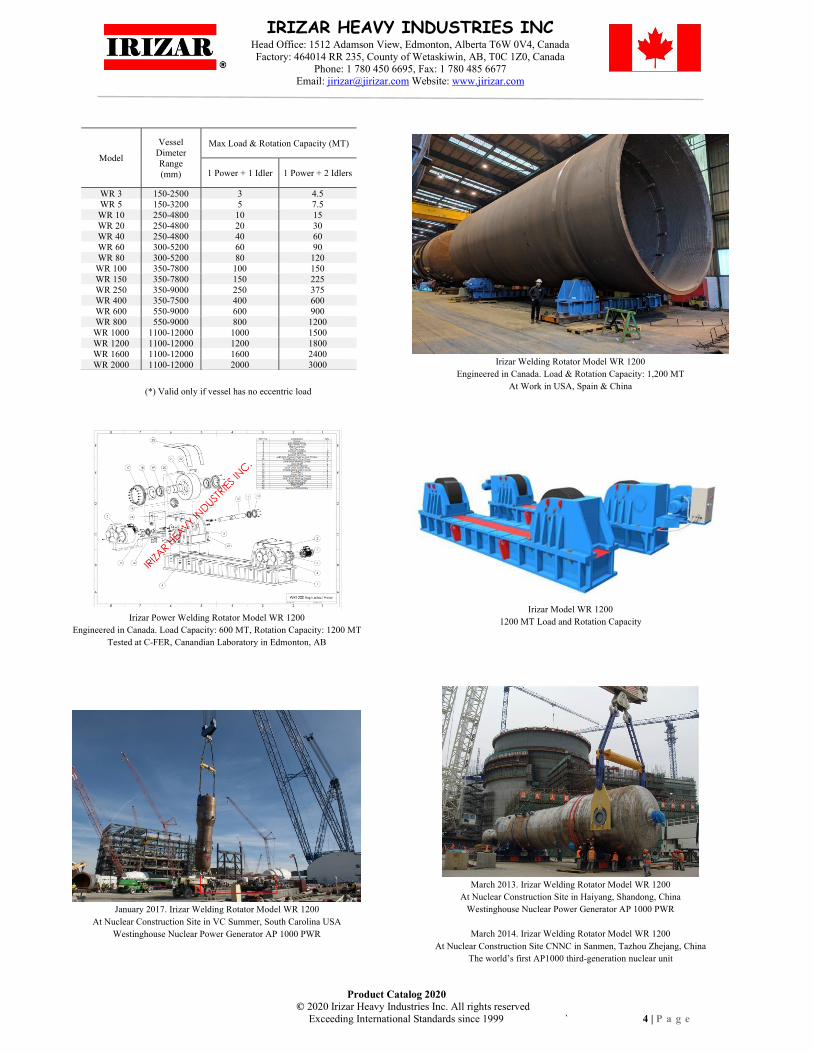
Irizar Welding Rotator Model WR 1200
Engineered in Canada. Load & Rotation Capacity: 1,200 MT
At Work in USA, Spain & China
Irizar Power Welding Rotator Model WR 1200
Engineered in Canada. Load Capacity: 600 MT, Rotation Capacity: 1200 MT
Tested at C-FER, Canandian Laboratory in Edmonton, AB
Irizar Model WR 1200
1200 MT Load and Rotation Capacity
January 2017. Irizar Welding Rotator Model WR 1200
At Nuclear Construction Site in VC Summer, South Carolina USA
Westinghouse Nuclear Power Generator AP 1000 PWR
March 2013. Irizar Welding Rotator Model WR 1200
At Nuclear Construction Site in Haiyang, Shandong, China
Westinghouse Nuclear Power Generator AP 1000 PWR
March 2014. Irizar Welding Rotator Model WR 1200
At Nuclear Construction Site CNNC in Sanmen, Tazhou Zhejang, China
The world’s first AP1000 third-generation nuclear unit

Product Catalog 2020
© 2020 Irizar Heavy Industries Inc. All rights reserved
Exceeding International Standards since 1999 ` 5 | P a g e
IRIZAR HEAVY INDUSTRIES INC Head Office: 1512 Adamson View, Edmonton, Alberta T6W 0V4, Canada
Factory: 464014 RR 235, County of Wetaskiwin, AB, T0C 1Z0, Canada Phone: 1 780 450 6695, Fax: 1 780 485 6677
Email: [email protected] Website: www.jirizar.com
Anti-Drift Turning Rolls, AD-WR Series
Anti-Drift Turning Rolls: Also known as Anti-Creep Rotators.
Minimize the screw effect (longitudinal displacement) while vessel
is rotating. Axial vessel accuracy of ± 3.0 mm. Anti-Drift Welding
Rotators from 100 to 3000 MT
Standard Package
1. One Power Roll with Control Box and Remote-Control Box
2. One Idler Roll with up/down servo motor on both wheels
3. Manual Anti-Drift Controlled; it means, controlled by a hand
control for up/down motors
4. Operation Manual with Electrical Diagram
5. One year Warranty
Optional: PLC & Sensor Automatic Anti-Drift Controlled
Video
3000 MT, Irizar Anti-Drift Welding Rotator Model AD-WR 3000
3000 MT (6,600,000 #) Load and Rotation capacity
Model
Load &
Rotation
Capacity
(MT)
Rotation
speed
(mm/min)
Power
(kW)
Vessel
Diameter
Range
(mm)
Wheel
(mm) Dimensions
L*H*W1*W2 (mm)
Weight
(MT) Diameter Width
AD WR 100 100 100-1000 2*3.0 1000-8000 500 260 5300*1070*1000*600 6.24
AD WR 150 150 100-1000 2*4.0 1000-8000 500 260 5700*1140*1050*650 7.15
AD WR 250 250 100-1000 2*5.5 1000-9000 660 260 5700*1250*1140*700 13.00
AD WR 400 400 100-1000 2*5.5 1200-9000 700 300 6600*1450*1320*830 22.75
AD WR 600 600 100-1000 2*7.5 1500-9000 900 360 7200*1845*1650*1000 35.75
AD WR 800 800 100-1000 2*11.0 2000-9000 900 380 7900*1845*2000*1300 45.50
AD WR 1000 1000 100-1000 2*11.0 2000-9000 1000 400 7900*1860*2100*1500 52.00
AD WR 1200 1200 100-1000 2*11.0 2000-9000 1000 450 7900*1860*2150*1600 62.40
AD WR 1600 1600 100-1000 2*20.00 2000-9000 1200 600 7900*1860*2400*1800 143.00
AD WR 2000 2000 100-1000 2*24.0 2000-9000 1200 600 8500*1960*2560*1900 182.00
AD WR 3000 3000 100-1000 2*24 + 30 2000-4000 1500 800 10000*2695*3210*2440 300.00
500 MT, Irizar Model WR 500 with Anti-Drift
3000 MT, Irizar Anti-Drift Welding Rotator Model AD-WR 3000
1600 MT, Irizar Model Anti-Drift Power WR 1600
1600 MT, Irizar Model Anti-Drift Idler IR 1600

Product Catalog 2020
© 2020 Irizar Heavy Industries Inc. All rights reserved
Exceeding International Standards since 1999 ` 6 | P a g e
IRIZAR HEAVY INDUSTRIES INC Head Office: 1512 Adamson View, Edmonton, Alberta T6W 0V4, Canada
Factory: 464014 RR 235, County of Wetaskiwin, AB, T0C 1Z0, Canada Phone: 1 780 450 6695, Fax: 1 780 485 6677
Email: [email protected] Website: www.jirizar.com
Self-Aligned Tank Turning Rolls, SAR Series Self Aligned Rotators also known as: Self Aligning (Adjusted, Alignment, Adjustment) Rollers
Model
Load &
Rotation
Capacity
(MT)
Rotation
speed
(mm/min)
Power
(kW)
Torque
(Nm)
Vessel
Diameter
Range
(mm)
Wheel
(mm)
Dimensions
L*W*H (mm) Weight
(MT) Diameter Width Power Roll Idler Roll
SAR 5 5 100-1000 0.75 3188
Chart
Next Page
250 140 1620*690*700 1380*380*700 0.85
SAR 10 10 100-1000 1.10 7652 300 170 1880*780*820 1454*390*820 1.20
SAR 20 20 100-1000 1.50 13093 350 180 2150*960*850 1700*480*850 2.00
SAR 40 40 100-1000 3.00 20405 400 200 2600*1000*1100 2200*500*1100 3.00
SAR 60 60 100-1000 4.00 30608 450 220 3000*1100*1150 2500*540*1150 4.00
SAR 80 80 100-1000 4.00 34009 500 240 3200*1200*1200 2700*620*1200 4.50
SAR 100 100 100-1000 5.50 46800 500 260 3500*1200*1400 3000*750*1400 5.50
SAR 150 150 100-1000 3.0*2 51900 500 220 3500*1200*1400 3000*750*1400 6.00
SAR 250 250 100-1000 5.5*2 93600 660 260 5010*1200*1600 3800*790*1600 12.00
SAR 500 500 100-1000 7.5*2 124000 800 300 5800*1400*2000 5000*1000*2000 28.00
Features
1. Designed and Engineered in Canada; made in China
2. Prototype static and dynamic tested at full capacity by Canadian Testing
Laboratory
3. Rollers align itself with the vessel diameter. Enable weight distribution in four
idler wheels on idler roll and four motorized wheels on power rotator
4. Rotators wheels from SAR 5 up to SAR 100 are made of Cast Iron; covered with
heavy duty rubber HSA80, and two steel rings at the side. Rotators wheels from
SAR 150 up to SAR 150 are made of Cast Steel ASTM 80-40 or equivalent; then,
quenched and tempered at 43 ~ 45 HRC (Rockwell C)
5. Remote Control Box with 12 m cable. Control: Forward/Stop/Reverse/ Variable
speed adjustment with digital display in mm/min
6. Increase power rotation capacity up to 50% more by adding extra idler; table
sheet next page. Valid only when: a) Vessel has no eccentricity loads, b) Each
rotator takes one third of the weight
Quality
1. Engineered in Canada; made in China
2. Canadian Standard Association CSA or QPS label SPE 1000-99: On main control
box. Ask when ordering.
3. CE Mark Certificate of Conformity No 181108/JIR/05; issue by Consultants
Europe BV in The Netherlands
4. Gearbox’s shells made of cast iron ASTM-A48-A48M or equivalent
5. Open gears made of Q235 steel or equivalent
6. Shafts made of ANSI-1045 or equivalent
7. Motors and control box with IP 54 protection against dust and heavy rain
8. Frequency driver made by TECO Westinghouse
9. Shot blasted ISO 8501-SA2.5
3D: SAR 5 - SAR 100 3D: SAR 150 - SAR 500 Photos/Video
Standard Package: 1. One Power Roll, dual motor, with
Control Box and Remote Control Box with 12 m cable, 2.
One idler roll, 3. Operation Manual with Electric
Diagram, 4. One year Warranty
Work Pieces with Eccentric Loads ≥ 25 inches of GC.
Select the Rotator Model: Rotation Capacity (MT) ≥ 5 x
Vessel Weight (MT) x GC (inches) / Vessel Radius
(inches). In addition, Brake’s motor may be required if:
Vessel Radius (inches) x 0.7 ≥ GC (inches)
Optional
1. Foot Pedal. Control: Forward/Stop/Reverse
2. Wireless Remote Control: With 60 m reach and 128
channels. Control: Forward/Stop/Reverse/Variable
speed adjustment with digital display in mm/min
3. Interface wiring for PLC control
4. Turning rolls mounted over idler or motorized bogie
with constant speed of 1.5 m/min; or, variable speed
from 0.15 to 1.5 m/minute
5. Brake Motors for vessels with large “eccentricity”.
It means, large GC offset from the tank rotation
center line
6. Rotator’s wheels covered with polyurethane
HSA95. Ideal for construction of stainless-steel
tanks. Available for rollers up to SAR 500.
7. Synchronized Device: Synchronize rotation speed
of two power rotators

Product Catalog 2020
© 2020 Irizar Heavy Industries Inc. All rights reserved
Exceeding International Standards since 1999 7 | P a g e
IRIZAR HEAVY INDUSTRIES INC Head Office: 1512 Adamson View, Edmonton, Alberta T6W 0V4, Canada Factory: 464014 RR 235, County of Wetaskiwin, AB, T0C 1Z0, Canada
Phone: 1 780 450 6695, Fax: 1 780 485 6677 Email: [email protected] Website: www.jirizar.com
Vessel sits on Four Wheels within the Roller’s Self Adjustable Zone
Table # 1 (Maximum Load Capacity)
Model
Vessel
Diameter
Range
(mm)
Max Load and Rotation Capacity (MT)
1 Power + 1 Idler 1 Power + 2 Idlers
SAR 5 770-2300 5 7.5
SAR 10 920-2800 10 15
SAR 20 1170-3500 20 30
SAR 40 1400-5200 40 60
SAR 60 1550-4800 60 90
SAR 80 1730-5000 80 120
SAR 100 2010-5500 100 150
SAR 150 2810-6000 150 225
SAR 250 2810-8000 250 375
SAR 500 3110-8000 500 750 (*) Valid only if vessel has no eccentric load
Vessel sits only on Bottom Wheels Table # 2 (Reduced Load Capacity)
Model
Vessel
Diameter
Range
(mm)
Max Load and Rotation Capacity (MT)
1 Power + 1 Idler 1 Power + 2 Idlers
SAR 5 250-760 3.75 5.62
SAR 10 320-910 7.50 11.25
SAR 20 500-1160 15.00 22.50
SAR 40 900-1390 30.00 45.00
SAR 60 750-1540 45.00 67.50
SAR 80 850-1720 60.00 90.00
SAR 100 1000-2000 75.00 112.50
SAR 150 1100-2800 112.50 168.75
SAR 250 1800-2800 187.50 281.25
SAR 500 1800-3100 375.00 562.50
(*) Valid only if vessel has no eccentric load
Advantage
1. Self Aligned Welding Rotator (SAR): Adjust itself to vessel
diameters within the Roller’s Self Adjustable Zone (Table # 1);
therefore, eliminate downtime. Conventional Welding
Rotators (WR): Require manually adjustment for setting up
center to center distance between wheels. It is made by means
of nuts and bolts; imply, downtime for adjust and torque.
2. SAR Rotator Set (power & idler) has eight wheels; four of
them motorized. WR rotator set has only four wheels; two of
them motorized. SAR Rotator provide: a) Extra support to
avoid tank deformation; when the vessel sits on wheels; b)
Additional friction between tank and wheels; it helps to reduce
the possibility of tank spin when eccentricity is an issue.
Facts
1. Self Aligned Power Rotator has four
motorized wheels
2. Self Aligned Set provides provide better
weight distribution
Disadvantage
When vessel sits only on bottom wheels (Table # 2),
the SAR Rollers load capacity is reduced.
500 MT, Irizar Model SAR 500
500 MT Irizar Model SAR 500 at work in Saudi Arabia

Product Catalog 2020
© 2020 Irizar Heavy Industries Inc. All rights reserved
Exceeding International Standards since 1999 8 | P a g e
IRIZAR HEAVY INDUSTRIES INC Head Office: 1512 Adamson View, Edmonton, Alberta T6W 0V4, Canada Factory: 464014 RR 235, County of Wetaskiwin, AB, T0C 1Z0, Canada
Phone: 1 780 450 6695, Fax: 1 780 485 6677 Email: [email protected] Website: www.jirizar.com
500 MT, Irizar Model SAR 500 at work in UAE
Welding Rotator Model SAR 100
Engineered in Canada, Tested at C-FER, Canandian Laboratory
Double Wheel Self Aligned Model SAR 40
This is a custom-built roller with sixteen wheels; eight of
them motorized
Application
1. When extra wheels are required to avoid work piece
deformation; while sitting on wheels.
2. When additional friction is required to avoid spin
3. For Wind Turbine Blade construction; and, other
industrial applications Double Wheel Self Aligned Welding Rotor Model SAR 40
Self Aligned Welding Rolls Model SAR 100
Self Aligned Welding Rolls Model SAR 150
Self Aligned Welding Rolls Model SAR 80
Gears Self Aligned Welding Rotator Model SAR 40
Product Catalog 2020
© 2020 Irizar Heavy Industries Inc. All rights reserved
Exceeding International Standards since 1999 9 | P a g e
IRIZAR HEAVY INDUSTRIES INC Head Office: 1512 Adamson View, Edmonton, Alberta T6W 0V4, Canada Factory: 464014 RR 235, County of Wetaskiwin, AB, T0C 1Z0, Canada
Phone: 1 780 450 6695, Fax: 1 780 485 6677 Email: [email protected] Website: www.jirizar.com
Chain Welding Rotator, CWR Series
Application: Chain Welding Rotators are used for construction of light gauge vessels made
of stainless steel or aluminum; very common on the Brewing and Food Industries; and, also
on the Cosmetic and Pharmaceutic Industries. This rotator is also used for the construction of
Fiberglass Tanks.
Designed: Rollers are designed to prevent the tank sits on the roller’s wheels, which may lead to produce indentation, scratches and other damages on thin wall tanks. The work piece sits
on a chain covered with heavy duty rubber.
Idler Bogies on CWR 20: For user convenience, power rotator and idler rotator come with
idler bogies; very friendly to adjust tank length, and also to move forward the tank to another station; or even, to move away from the fabrication shop.
Model
Load &
Rotation
Capacity (MT)
Speed
(mm/min)
Power
(kW)
Vessel Diameter
(mm)
Wheel
(mm)
Dimensions
L*W*H (mm) Weight
(MT) Diameter Width Power Roll Idler Roll
CWR-5 5 150 -1500 2 @ 0.37 500 – 2,000 320 150 2800 *600*500 2500*500*500 1.50
CWR-20 20 100-1000 2 @ 1.50 1,000 – 5,000 420 240 3450*1030*658 3450*1000*658 3.50
Features
1. CWR-5: Fix Base 2. CWR-20: Idler Bogies on
power and idler rotator Center to center distance
between wheels: 2,250 mm
3. Motors and Control Box IP54 class
Standard Package
1. One Power Roll with Control Box and Remote-
Control Box with 12 m cable. Control: Forward/Stop/Reverse/Variable speed
adjustment with digital display in mm/min
2. One Idler Roll 3. Operation Manual
4. Electric Diagram 5. One year Warranty
Optional
1. 1. For Fit Up we can supply additional two idler
rotators. Therefore, the first shell sits on one power and one idler; the second shell sits on two extra idlers.
2. Wireless Remote Control: With 60 m reach and 128
channels. Control: Forward/Stop/Reverse/Variable
speed adjustment with digital display in mm/min
3. Foot Pedal. Control: Forward/Stop/Reverse
Custom Built Rotator
Anti-Drift Turning Rolls
Bed Rollers
Concrete Drum Welding Positioner
Cone Rotators
1BFit Up Rolls
I Beam Rotators
Large Diameter Rotators
Lifting Scissor Rollers
2BPipe Rotator PR-1
3BPower Pole Rotators
Rotators with Bogies
Rotators with Screw Device Adjustment
Shot Blasting & Painting Rotators
Turbine Rotator
Certificates
CE Mark
WR 1200 Certificate
Beam Rotator
Dodecagon Power Pole Rotator
Welding Rotator Model WR 100 with Bogies
At work in Calgary, AB, Canada
Concrete Drum Positioner
Chain Welding Rotator Model CWR-5
Bed Rollers
Photos/Video
Product Catalog 2020
© 2020 Irizar Heavy Industries Inc. All rights reserved
Exceeding International Standards since 1999 10 | P a g e
IRIZAR HEAVY INDUSTRIES INC Head Office: 1512 Adamson View, Edmonton, Alberta T6W 0V4, Canada Factory: 464014 RR 235, County of Wetaskiwin, AB, T0C 1Z0, Canada
Phone: 1 780 450 6695, Fax: 1 780 485 6677 Email: [email protected] Website: www.jirizar.com
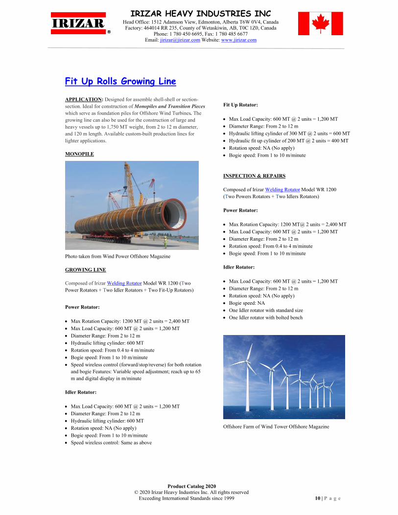
Fit Up Rolls Growing Line
APPLICATION: Designed for assemble shell-shell or section-
section. Ideal for construction of Monopiles and Transition Pieces
which serve as foundation piles for Offshore Wind Turbines. The
growing line can also be used for the construction of large and
heavy vessels up to 1,750 MT weight, from 2 to 12 m diameter,
and 120 m length. Available custom-built production lines for
lighter applications.
MONOPILE
Photo taken from Wind Power Offshore Magazine
GROWING LINE
Composed of Irizar Welding Rotator Model WR 1200 (Two
Power Rotators + Two Idler Rotators + Two Fit-Up Rotators)
Power Rotator:
• Max Rotation Capacity: 1200 MT @ 2 units = 2,400 MT
• Max Load Capacity: 600 MT @ 2 units = 1,200 MT
• Diameter Range: From 2 to 12 m
• Hydraulic lifting cylinder: 600 MT
• Rotation speed: From 0.4 to 4 m/minute
• Bogie speed: From 1 to 10 m/minute
• Speed wireless control (forward/stop/reverse) for both rotation
and bogie Features: Variable speed adjustment; reach up to 65
m and digital display in m/minute
Idler Rotator:
• Max Load Capacity: 600 MT @ 2 units = 1,200 MT
• Diameter Range: From 2 to 12 m
• Hydraulic lifting cylinder: 600 MT
• Rotation speed: NA (No apply)
• Bogie speed: From 1 to 10 m/minute
• Speed wireless control: Same as above
Fit Up Rotator:
• Max Load Capacity: 600 MT @ 2 units = 1,200 MT
• Diameter Range: From 2 to 12 m
• Hydraulic lifting cylinder of 300 MT @ 2 units = 600 MT
• Hydraulic fit up cylinder of 200 MT @ 2 units = 400 MT
• Rotation speed: NA (No apply)
• Bogie speed: From 1 to 10 m/minute
INSPECTION & REPAIRS
Composed of Irizar Welding Rotator Model WR 1200
(Two Powers Rotators + Two Idlers Rotators)
Power Rotator:
• Max Rotation Capacity: 1200 MT@ 2 units = 2,400 MT
• Max Load Capacity: 600 MT @ 2 units = 1,200 MT
• Diameter Range: From 2 to 12 m
• Rotation speed: From 0.4 to 4 m/minute
• Bogie speed: From 1 to 10 m/minute
Idler Rotator:
• Max Load Capacity: 600 MT @ 2 units = 1,200 MT
• Diameter Range: From 2 to 12 m
• Rotation speed: NA (No apply)
• Bogie speed: NA
• One Idler rotator with standard size
• One Idler rotator with bolted bench
Offshore Farm of Wind Tower Offshore Magazine
Product Catalog 2020
© 2020 Irizar Heavy Industries Inc. All rights reserved
Exceeding International Standards since 1999 11 | P a g e
IRIZAR HEAVY INDUSTRIES INC Head Office: 1512 Adamson View, Edmonton, Alberta T6W 0V4, Canada Factory: 464014 RR 235, County of Wetaskiwin, AB, T0C 1Z0, Canada
Phone: 1 780 450 6695, Fax: 1 780 485 6677 Email: [email protected] Website: www.jirizar.com
1 MT, Irizar Pipe Rotator Model PR 1
Pipe Rotator,Series
Pipe Rotator Model PR 1
Load and Rotation Capacity: 1 MT
Pipe Diameter: From 20 up to 1,000 mm
Linear Speed: From 80-2,400 mm/minute
Input Power: 110/115 V, 50/60 Hz, 1 P
Power: 0.18 kW, DC motor
Torque: 1000 Nm
Control box: Forward, Stop, Reverse,
analog speed control
Wheel Diameter: 200 mm
Wheel Width: 50 mm
Foot Control: Included
Power (L*W*H): 300*250*370 mm
Idler (L*W*H): 500*200*370 mm
Weight: 65 kilos
PR Series
Photos/Video
Pipe Rotator PR Series, also known as Pipe Spool Rotator. It is used for pipe spool
fabrication with long pipes with high eccentric loads. It has an assisting pressure column for
pipe clamping.
Technical Information: a) Manual screw adjustment device to modify center to center wheel
distance in both power and idler rolls, b) Column turning: ± 90° (manual), c) Working height
(floor to roll wheels): Approx. 650 mm
Standard Package: 1. One Power Roll with assisting pressure column. Remote Control Box
with 12 m cable. Control: Forward/Stop/Reverse/Variable speed adjustment with digital display
in mm/minute, 2. One Idler Roll, 3. Operation Manual, 4. Electric Diagram, and 5. One year
Warranty
Optional: a) Foot Pedal: Forward/Stop/Reverse, b) Wireless Remote Control: Up to 60 m
reach. Control: Forward/Stop/Reverse/Variable speed adjustment with digital display in
mm/min
Model
Load &
Rotation
Capacity
(MT)
Rotation
Speed
(mm/min)
Pipe Diameter
(mm)
Column Dimensions
L*W*H
(mm)
Power
(kW)
Weight
(MT) Assisting
Pressure
(kg)
Lifting
Speed
(mm/min)
PR 5 5 100-1000 50-600 ≤ 450 145 1500*1200*1800 0.75 1.30
PR 5L 5 70-1700 100-1200 ≤ 450 145 1500*1200*2300 0.75 1.50
PR 10 10 70-1700 50-600 ≤ 450 145 1700*1300*1800 1.10 2.50
PR 10L 10 70-1700 100-1200 ≤ 450 145 1700*1300*2300 1.10 2.70
PR 25 25 70-1700 100-1500 ≤ 450 500 1900*1500*3000 3.00 3.00
PP Series
Pipe Rotator PP Series is used for pipe spool fabrication with short pipes with high eccentric
loads. It has a tilt angle of ± 45º, and an assisting pressure column for pipe clamping.
Technical Information: a) Manual adjustment for modifying center to center wheel distance, b)
Dimensions and weight subject to change without notice.
Standard Package: 1. Power Roll with Remote Control Box with 12 m cable. Control:
Forward/Stop/Reverse/Variable speed adjustment with digital display in mm/minute, 2.
Operation Manual, 3. Electric Diagram, 4. One year Warranty
Optional: a) Foot Pedal. Control: Forward/Stop/Reverse, b) Idler support with adjustable height
mounted over manual bogies, c) Wireless Remote Control: Up to 60 m reach. Control:
Forward/Stop/Reverse/Variable speed adjustment digital display in mm/min
Photos/Video
Model
Load &
Rotation
Capacity
(MT)
Rotation
Speed
(mm/min)
Tilt
Angle
Pipe
Diameter
(mm)
Column Dimensions
L*W*H
(mm)
Power
(kW)
Weight
(MT) Assisting
Pressure (kg)
Lifting Speed
(mm/min)
PP-1 1 70-1700 ± 45º 50-426 ≤ 450 300 1200*800*1800 0.75 1.00
PP-2 2 70-1700 ± 45º 50-630 ≤ 450 300 1200*800*1800 1.10 1.40
PP-3 3 70-1700 ± 45º 50-800 ≤ 450 300 1300*800*1800 1.10 1.50

Product Catalog 2020
© 2020 Irizar Heavy Industries Inc. All rights reserved
Exceeding International Standards since 1999 12 | P a g e
IRIZAR HEAVY INDUSTRIES INC Head Office: 1512 Adamson View, Edmonton, Alberta T6W 0V4, Canada Factory: 464014 RR 235, County of Wetaskiwin, AB, T0C 1Z0, Canada
Phone: 1 780 450 6695, Fax: 1 780 485 6677 Email: [email protected] Website: www.jirizar.com
Welding Positioners, WP Series
WP Series, Fixed height Irizar Model WP 5
AH-WP Series, Adjustable height
88,000 # @ 47.25” GC, Irizar Model CWP 40
Model
Load
Cap
(MT)
Power
(kW)
Max
Gra
vit
y C
ente
r
(mm
)
Max
Ecc
entr
icit
y
(mm
)
Table
Max
Work
Pie
ce
Dia
. @
90°
Til
t
(mm
)
Torque
(Nm)
Til
t A
ng
le (
°)
Dimensions
L*W*H
(mm)
Weight
(MT)
Speed (RPM)
Surf
ace
ro
tati
on ç
(m
m)
Dia
met
er
(mm
)
Rota
tion
Til
t
Rota
tion
Til
t
Rota
tion
Til
t
WP 0.3 0.30 0.37 N/A 200 150 0.10~1.0 N/A 150 600 800 1286 N/A 0-90° 930*660*720 0.3
WP 0.6 0.60 0.75 0.75 200 150 0.10~1.0 1.09 210 1000 1500 2600 2676 0-90° 1200*900*850 0.7
WP 1 1 1.10 1.50 250 200 0.05~0.5 0.80 240 1200 2000 8345 7257 0-120° 1400*1200*1200 1.0
WP 3 3 1.50 2.20 300 200 0.05~0.5 0.23 250 1400 2100 8519 37617 0-120° 2100*1500*1350 2.5
WP 5 5 2.20 3.00 300 200 0.05~0.5 0.16 280 1500 2500 14913 71119 0-120° 2200*1500*1450 3.7
WP 10 10 3.00 5.50 400 200 0.05~0.2 0.24 280 2000 3200 71720 91029 0-120° 2700*2000*1850 5.8
WP 20 20 4.00 7.50 450 200 0.05~0.5 0.10 290 2300 3200 90000 315000 0-135° 3300*2230*2000 11
WP 30 30 7.50 11.0 500 200 0.05~0.5 0.10 290 3000 3400 120000 420000 0-135° 3675*3000*2750 18
WP 40 40 11.0 11.0 500 200 0.05~0.5 0.10 300 3500 3400 142000 500000 0-135° 4000*3000*3300 22
WP 50 50 11.0 15.0 500 200 0.05~0.5 0.10 300 3500 4200 163000 550000 0-135° 4525*3500*4100 27
3D: WP 0.6 - WP 1 3D: WP 3 - WP 10 Photos Video
Features
1. Designed and Engineered in Canada; made in China
2. Main Control Box controls tilt rotation (*): Forward/Stop/Reverse
3. Remote Control Box with 12 m cable. Control:
Forward/Stop/Reverse/Variable speed adjustment on table rotation.
Digital display in mm/min is included
4. Tilt break through gear reducer motor or motor with electric break
5. “T” shaped channels on table surface
6. Octagonal Tables of WP 30 and larger. Octagon size has an inscribed
circumference of 2.3 m Ø.
7. Quality: 1. Gearbox’s shells made of cast iron ASTM-A48-A48M or
equivalent; 2. Open gears made of Q235 steel or equivalent; 3. Shafts
made of ANSI 1045 or equivalent; 4. Motors and control box with IP 54
protection against dust and heavy rain; 5. Frequency driver made by
TECO Westinghouse; 6. Shot blasted: Ensure the paint holds longer
8. Safety: WP 20 and larger adopt double motor and double gear on tilt
(*) Variable speed on tilt: Optional
Standard Package: 1. Welding Positioner with Control Box
and Remote Control Box with 12 m cable, 2. Operation
Manual with Electric Diagram, 3. One year Warranty
Optional
1. Foot Pedal. Control table rotation:
Forward/Stop/Reverse
2. Tilt variable speed
3. Wireless remote control: With 60 m reach and 128
channels. Control table rotation: Forward/Stop/Reverse/
4. Variable speed adjustment with digital display.
5. Interface wiring for PLC control
6. Table extension arms for reach larger work pieces on
WP 30 and larger. Max work piece diameter in red
color table above
7. Synchronized Device: Synchronize rotation speed of
two WP. Increase rotation capacity 100% when both
positioners are placed one in front of other and work
piece is loaded on tables at 90° (vertical position)
8. CE mark
Model Work Piece Gravity Center (mm)* VS Load Capacity (kg or MT) **
Max
Eccentricity
Notes:
(*) The
maximum
gravity center
measured from
the table surface
(**) The
maximum load
capacity when
the positioner’s
table is at 90° tilt
(mm) 200 250 300 350 400 450 500 600 700 800 900 1000 1200 1400 1600 1800
(mm)
WP 0.3 Kgs 300 240 200 171 150 133 120 100 150
WP 0.6 Kgs 600 480 400 342 300 266 240 200 150
WP 1 Kgs 1000 833 714 625 555 500 416 357 312 277 200
WP 3 Kgs 3000 2571 2250 2000 1800 1500 1285 1125 1000 200
WP 5 Kgs 5000 4285 3750 3333 3000 2500 2142 1870 1666 200
WP 10 MT 10 8.8 8 6.6 5.7 5 4.4 4 3.3 2.8 2.5 2.2 200
WP 20 MT 20 17.1 15 13.3 12 10 8.5 7.5 6.6 200
WP 30 MT 30 25.7 22.5 20 18 15 12.8 11.2 10 200
WP 40 MT 40 35 31.1 28 23.3 20 17.5 15.5 200
WP 50 MT 50 44.4 40 33.3 28.5 25 22.2 200
Product Catalog 2020
© 2020 Irizar Heavy Industries Inc. All rights reserved
Exceeding International Standards since 1999 13 | P a g e
IRIZAR HEAVY INDUSTRIES INC Head Office: 1512 Adamson View, Edmonton, Alberta T6W 0V4, Canada Factory: 464014 RR 235, County of Wetaskiwin, AB, T0C 1Z0, Canada
Phone: 1 780 450 6695, Fax: 1 780 485 6677 Email: [email protected] Website: www.jirizar.com
1 MT (2,200 #) @ 250 mm GC, Irizar Model WP 1
Notes
1. Custom-built Welding Positioners available
2. Rental: Available in Canada and USA
3. Concrete Drum Positioner
4. The information contained in this brochure is intended to be
accurate. However, the manufacturer reserves the right to make
changes in design which may not be included
0.6 MT (1,320 #) @ 200 mm GC, Irizar Model WP 0.6
5 MT (11,000 #) @ 300 mm GC, Irizar Model WP 5
10 MT (22,000 #) @ 400 mm GC, Irizar Model WP 10
At Work in Edmonton, AB, Canada
20 MT (44,000 #) @ 600 mm GC, Irizar Model WP 20
Shipped to Topeka, Kansas USA & Tatsumo, Japan
40 MT @ 1,200 mm GC, Irizar Model CWP 40
At work Portland, Oregon, USA
88,000 # @ 47.25” GC, Irizar Model CWP 40
At work Portland, Oregon, USA
Product Catalog 2020
© 2020 Irizar Heavy Industries Inc. All rights reserved
Exceeding International Standards since 1999 14 | P a g e
IRIZAR HEAVY INDUSTRIES INC Head Office: 1512 Adamson View, Edmonton, Alberta T6W 0V4, Canada Factory: 464014 RR 235, County of Wetaskiwin, AB, T0C 1Z0, Canada
Phone: 1 780 450 6695, Fax: 1 780 485 6677 Email: [email protected] Website: www.jirizar.com
Welding Positioners, CWP Series
60 MT @ 1,800 mm GC, Irizar Model CWP 60
132,000 # @ 70.86” GC, Irizar Model CWP 60
60 MT @ 1,800 mm GC, Irizar Model CWP 60
Model
Load
Cap
(MT)
Power
(kW)
Max
Gra
vit
y C
ente
r
(mm
)
Max
Ecc
entr
icit
y
(m
m)
Table
Max
Work
Pie
ce
Dia
. @
90°
Til
t
(mm
)
Torque
(N-m)
Til
t A
ng
le (
°)
Dimensions
L*W*H
(mm)
Weight
(MT)
Speed (RPM)
Tab
le S
urf
ace
to
rota
tio
n ç
(m
m)
Ro
tati
on
Til
t
Ro
tati
on
Til
t
Ro
tati
on
Til
t
CWP 30 30 11 2*5.5 1200 400
0.0
2 ~
0.2
0.0
1 ~
0.1
200 4000 120000 420000 0-90° 6370*2800*2300 33
CWP 40 40 11 2*7.5 1200 400 200 4000 142000 500000 0-90° 6370*2800*2300 34
CWP 50 50 15 2*7.5 1200 400 350 4000 163000 550000 0-90° 6370*2800*2300 35
CWP 60 60 18.50 2*11 1800 300 400 5500 195000 670000 0-90° 8100*4000*3100 65
CWP 70 70 22 2*11 1800 300 450 5500 250000 950000 0-90° 8100*4000*3100 67
CWP 80 80 22 2*15 1800 300 500 5500 335000 1460000 0-90° 8100*4000*3100 68
CWP 90 90 2*15 2*18.5 2000 300 500 6000 425000 1700000 0-90° 9300*4300*3500 72
CWP 100 100 2*15 2*18.5 2000 300 550 6000 470000 1900000 0-90° 9300*4300*3500 75
Features
1. Designed and Engineered in Canada; made in China
2. Control Box with emergency stop
3. Remote Control Box with 24 m cable. Control: Forward/Stop/Reverse/Variable
4. speed adjustment on table rotation and tilt. Digital display in RPM
5. Rotation variable speed from 0.02 to 0.20 RPM
6. Tilt variable speed from 0.01 to 0.10 RPM
7. Self lock worm gear boxes with electric brake to prevent table tilt when motor
stop
8. Octagon table within an inscribed circumference from 2.20 up to 3.00 m Ø.
9. Include “T” shaped channels at 45° on table surface
Quality
1. Engineered in Canada; made in China
2. Canadian Standard Association CSA or QPS label SPE 1000-99: On main control
box. Ask when ordering.
3. CE Mark Certificate of Conformity No 181108/JIR/05; issue by Consultants
Europe BV in The Netherlands
4. Gearbox’s shells made of cast iron ASTM-A48-A48M or equivalent
5. Open gears made of Q235 steel or equivalent
Photos/Video 6. Shafts made of ANSI-1045 or equivalent
7. Motors and control box with IP 54 protection against
dust and heavy rain
8. Frequency driver made by TECO Westinghouse
9. Shot blasted ISO 8501-SA2.5
10. Safety tilt device composed of a gas cylinder support
on gear to prevent table tilt in case a gear box brake
Standard Package
1. Welding Positioner with Control Box and Remote-Control
Box with 24 m cable
2. Operation Manual with Electric Diagram
3. One year Warranty
Optional
1. Table extension arms to reach larger work pieces. Arm’s
length: work piece OD + 0.70 m
2. Tilt angle from 0° to 135° forward
Model Work Piece Gravity Center (mm)* VS. Load Capacity (MT)**
Max
Eccentricity Notes:
(*) Maximum gravity center measured from the
table surface
(**) Maximum load capacity when the
positioner’s table is at 90 tilt
(mm) 1200 1400 1600 1800 2000 2200 2400 2600 2800 3000
(mm)
CWP 30 MT 30.0 25.7 22.5 20,0 18.0 16.3 15.0 13.8 12.8 12.0 400
CWP 40 MT 40.0 34.2 30.0 26.6 24.0 21.8 20.0 18.4 17.1 16.0 400
CWP 50 MT 50.0 42.8 37.5 33.3 30.0 27.2 25.0 23.0 21.4 20.0 400
CWP 60 MT 60.0 54.0 49.0 45.0 41.5 38.5 36.0 300
CWP 70 MT 70.0 63.0 57.2 52.5 48.4 45.0 42.0 300
CWP 80 MT 80.0 72.0 65.4 60.0 55.3 51.4 48.0 300
CWP 90 MT 90.0 81.8 75.0 69.2 64.2 60.0 300
CWP 100 MT 100.0 91.0 83.3 76.9 71.4 66.6 300

Product Catalog 2020
© 2020 Irizar Heavy Industries Inc. All rights reserved
Exceeding International Standards since 1999 15 | P a g e
IRIZAR HEAVY INDUSTRIES INC Head Office: 1512 Adamson View, Edmonton, Alberta T6W 0V4, Canada Factory: 464014 RR 235, County of Wetaskiwin, AB, T0C 1Z0, Canada
Phone: 1 780 450 6695, Fax: 1 780 485 6677 Email: [email protected] Website: www.jirizar.com
Head & Tail Stock, HT Series
Model
Load
Cap.
(MT)
Table
Diameter
(mm)
Adjustable
Rotation
Center
(mm)
Rotation
Speed
(RPM)
Elevation
Speed
(m/min)
Max
Eccen
(mm)
Torque
(Kg-m)
Power
(kW)
Weight
(MT)
HT-20
HT 1 1.0 800 800~1,500 0.15~1.50 1.0 150 210 2.0 1.50
HT 3 3.0 800 800~1,500 0.15~1.50 1.0 150 640 4.0 3.20
HT 5 5.0 800 800~1,500 0.10~1.00 0.6 150 900 6.0 5.10
HT 10 10 1,000 1,000~1,500 0.10~1.00 0.6 200 1,880 10.0 10.0
HT 15 15 1,000 1,000~1,500 0.10~1.00 0.6 200 3,360 16.0 13.0
HT 20 20 1,000 1,000~2,000 0.10~1.00 0.6 250 6,700 22.0 14.0
HT 30 30 1,000 1,000~2,000 0.10~1.00 0.6 250 8,500 24.0 16.0
HT 40 40 1,000 1,000~2,000 0.05~0.50 0.6 250 12,000 30.0 18.0
HT 50 50 1,000 1,000~2,000 0.05~0.50 0.6 250 15,000 32.0 23.0
HT 75 75 1,500 1,200~2,000 0.05~0.50 0.5 250 23,000 35.0 24.0
HT 100 100 1,500 1,200~2,000 0.05~0.50 0.5 250 31,000 45.0 26.0
Model Work Piece Gravity Center (mm)* VS Load Capacity (MT)**
Configuration
Head Stock:
Fixed
Tail Stock
Mounted over
idler bogies for
adjust work
piece length
(mm) 250 350 450 550 650 750 850 950 10000
HT 1 MT 1 0.70 0.50 0.45
HT 3 MT 3 2.10 1.50 1.35 1.15 1.00
HT 5 MT 5 3.50 2.50 2.25 1.92 1.66 1.47
HT 10 MT 10 7.00 5.00 4.50 3.80 3.20 2.80 2.63 2.50
HT 15 MT 15 10.50 7.50 6.70 5.70 5.00 4.40 3.90 3.75
HT 20 MT 20 14.20 11.00 9.00 7.70 6.60 5.80 5.20 5.00
HT 30 MT 30 21.40 16.66 13.64 11.54 10.00 8.80 7.80 7.50
HT 40 MT 40 28.57 22.22 18.18 15.38 13.33 11.00 10.40 10.00
HT 50 MT 50 35.70 27.00 22.00 19.00 16.00 14.00 13.00 12.00
HT 75 MT 75 53.00 41.00 34.00 28.00 25.00 22.00 19.00 18.00
HT 100 MT 100 71.00 55.00 45.00 38.00 33.00 29.00 26.00 25.00
Welding Positioner, PL Series
Model
Load
Cap.
(MT)
Table
Diameter
(mm)
Height
Adjustment
(mm)
Rotation
Speed
(RPM)
Elevation
Speed
(m/min)
Max
GC
(mm)
Max
Eccentricity
(mm)
Power
(kW)
Weight
(MT)
PL 1.0 1.00 900 800~1,900 0.15~1.50 1.00 300 200 3.50 1.50
PL 2.5 2.50 900 800~1,900 0.15~1.50 1.00 300 200 4.00 2.50
PL 5.0 5.00 1,200 800~1,900 0.02~0.20 0.45 300 200 8.00 3.50
PL 7.5 7.50 1,800 820~2,300 0.02~0.20 0.45 300 200 12.00 4.50
PL 10.0 10.0 1,800 820~2,300 0.02~0.20 0.45 300 200 18.50 5.50
Turntables, TT Series
Model
Load
Cap.
(MT)
Table
Diameter
(mm)
Rotation
Speed
(RPM)
Max
Eccentricity
(mm)
Dimensions
L*W*H
(mm)
Torque
(Nm)
Power
(kW)
Weight
(MT)
TT 0.5 0.5 800 0.10~1.00 200 800*800*400 80 0.18 0.90
TT 1 1 1000 0.10~1.00 200 1000*1000*500 100 0.25 1.00
TT 3 3 1500 0.05~0.50 200 1500*1500*600 400 0.55 1.10
TT 5 5 1500 0.05~0.50 200 1500*1500*650 600 0.75 1.30
TT 10 10 1800 0.05~0.50 200 1800*1800*650 1200 1.10 1.50
TT 20 20 2000 0.02~0.20 200 2000*2000*750 2400 1.50 2.50
TT 50 50 2500 0.015~0.15 200 2500*2500*750 6000 2.20 4.50
TT 75 75 2800 0.015~0.15 200 2600*2600*850 9000 3.00 6.00
TT 100 100 2800 0.010~0.10 200 2800*2800*1000 12000 4.00 7.80
Features
1. Designed and Engineered in Canada; made in China
2. Remote Control Box with 12 m cable length: 1) On Head Stock Model HT. Includes:
Variable speed on table rotation: Forward / Stop / Reverse; Digital display in RPM; and,
adjustable center rotation height: Up / Down; 2) On Turntable Model TT: Variable speed on
table rotation: Forward / Stop / Reverse; Digital display in RPM; 3) On Welding Positioner
Model PL. Includes: Variable speed on table rotation: Forward / Stop / Reverse; Digital
display in RPM; and, tilt speed control, and height adjustment: Up / Down
3. “T” shaped channels on table surface
Standard Package: a) Welding Positioner PL or
Head & Tail Stock or Turntable, b) Control Box
and Remote Control Box, c) Operation Manual
with Electric Diagram, d) One year Warranty
Optional: a) Foot control pedal. Control:
Forward/Stop/Reverse, b) Extension arms on
Turntable for increase table diameter, c) CE mark
Photos
Photos-Video

Product Catalog 2020
© 2020 Irizar Heavy Industries Inc. All rights reserved
Exceeding International Standards since 1999 16 | P a g e
IRIZAR HEAVY INDUSTRIES INC Head Office: 1512 Adamson View, Edmonton, Alberta T6W 0V4, Canada Factory: 464014 RR 235, County of Wetaskiwin, AB, T0C 1Z0, Canada
Phone: 1 780 450 6695, Fax: 1 780 485 6677 Email: [email protected] Website: www.jirizar.com
Welding Manipulators, WM Series Manufacture Welding Manipulators, also known as: Welding Booms and Welding Columns
IRIZAR 3D Model WM 4040 & SAR 40
Model
WM YYXX
SS = Self Stand
Boom Column Trolley or Base Self Stand
Po
wer
(k
W)
Est
imat
ed P
ack
ing
Dim
.
Co
lum
-Bo
om
(L
*W
*H
)
(m
)
Wei
gh
t (M
T)
(A)
Vertical
Expansion (m)
(B)
Horizontal
Expansion (m)
Up
–D
ow
n
Sp
eed
(m
/min
)
In–
Ou
t
Sp
eed
(m
/min
)
Tra
vel
ing
Pre
cisi
on
Sp
eed
(%
)
Max
lo
ad a
t b
oo
m
extr
emit
y (
Kil
os
@ 1
2”
GC
)
Ro
tati
on
An
gle
± 1
80
º
(C)
hei
gh
t (m
)
Pac
kin
g D
im
D*
E*
0.3
0
(m)
(F)
Rai
l ç
to ç
(m
m)
spee
d (
m/m
in)
Effective Min-Max Effective Min-Max
SS WM 1530 1.5 0.53~2.03 3.0 1.0~4.0 1.00
0.1
2 t
o 1
.20
± 2
%
200 manual 3.20 N/A N/A N/A 2.75 3.50*1.40*0.60 2.00
WM 3030 3.0 0.75~3.75 3.0 1.0~4.0 1.00 200 motorized 5.50 2.40*1.90*0.3 1600 1.50 2.75 5.50*1.40*0.70 3.00
WM 4040 4.0 0.75~4.75 4.0 1.0~5.0 1.00 200 motorized 6.50 2.40*1.90*0.3 1600 1.50 2.75 6.50*1.50*0.80 4.00
WM 5050 5.0 1.10~6.10 5.0 1.0~6.0 0.90 300 motorized 7.80 2.40*2.10*0.3 1798 1.50 3.35 7.80*1.60*0.90 5.00
WM 6060 6.0 1.10~7.10 6.0 1.0~7.0 0.90 300 motorized 9.00 2.40*2.10*0.3 1798 1.50 3.35 9.80*1.70*1.00 6.50
SS WM 7060 7.0 1.20~8.20 6.0 1.0~7.0 0.90 300 motorized 10.00 3.20*2.40*0.3 NA NA 4.25 10.80*1.70*1.1 11.00
SS WM 8060 8.0 1.20~9.20 6.0 1.0~7.0 0.90 300 motorized 11.00 3.20*2.40*0.3 NA NA 4.25 11.80*1.70*1.2 13.00
Standard Package: 1) Welding Manipulator mounted on motorized trolley; 2)
Control Box & Remote-Control Box, 3) Operation Manual with Electrical
Diagram. 4) One year Warranty
Features
1. Boom expansion speed (in-out): From 0.12 to 1.20 m/min
2. Boom lifting (up-down) speed: Constant
3. Trolley motorized travel speed: 1.5 m/minute
4. Column rotation angle: ± 180º
5. Column rotation speed: Approx. 0.30 RPM
6. Main Control Box fixed on trolley: Control column rotation:
Forward/Stop/Reverse.
7. Remote Control Box with 12 m cable length. Control: Variable speed on
boom in-out: Forward/Stop/Reverse. Digital display in mm/min Also
control boom lifting: Up/Stop/Down
8. Boom Features:
• Standard: For Min 1.50 m ID.
• Custom Built: Min 20” ID using WM 3030
• Counterweight system to ensure smooth vertical travel
• Cable organizer: Included
9. Power Source Platforms: Available on Trolley. Max load capacity of 1.5
MT. Platforms can handle: Lincoln Power Waves AC/DC 1000, or DC-
1500/AC-1200, or equivalent
3D Model Photos Videos
10. Gearbox’s shells made of cast iron ASTM-A48-A48M or
equivalent
11. Open gears made of Q235 steel or equivalent
12. Shafts made of ANSI 1045 or equivalent
13. Motors and control box with IP 54 protection against dust and
heavy rain
14. Frequency driver made by TECO Westinghouse
15. Stress Relieved on Column and Boom
16. Shot blasted ISO 8501-SA2.5
Welding Manipulator Guide Selection
1. Determine the largest tank diameter to be fabricated
2. Determine the largest longitudinal seam to be welded
3. Select the WM YYXX
4. Y = Maximum effective boom vertical expansion (up-down) in m
5. X = Maximum effective boom horizontal expansion (in-out) in m
6. Check if column height of the selected WM fits below your
overhead crane; otherwise, we can custom built column height
Safety
1. Boom anti-fall safety device on WM 3030 and up 2. Trolley anti-fall safety device 3. Limit switches in all directions
Product Catalog 2020
© 2020 Irizar Heavy Industries Inc. All rights reserved
Exceeding International Standards since 1999 17 | P a g e
IRIZAR HEAVY INDUSTRIES INC Head Office: 1512 Adamson View, Edmonton, Alberta T6W 0V4, Canada
Factory: 464014 RR 235, County of Wetaskiwin, AB, T0C 1Z0, Canada Phone: 1 780 450 6695, Fax: 1 780 485 6677
Email: [email protected] Website: www.jirizar.com
Boom Configuration for Longitudinal and Circumferential (SAW) Submerged Arc Welding
3D Model for Single Head
Quality
1. Engineered in Canada; made in China
2. Welding Equipment: Lincoln Electric Company; made in USA
3. Canadian Standard Association CSA or QPS label SPE 1000-99:
On main control box. Ask when ordering.
4. CE Mark Certificate of Conformity No 181108/JIR/05; issue by
Consultants Europe BV in The Netherlands
Optional
1. Wireless Control
2. Submerged Arc Welding Equipment
For Single Wire with Idealarc Lincoln Power Source DC 1000
For Tandem Wire with Lincoln Power Wave AC/DC 1000
3. Irizar Manual Cross Slide for Single Head
Max 50 kilos @ 12” GC. Stroke 80 x 80 mm
4. Irizar Motorized Cross Slide for Single Head
Max 100 kilos @ 12” GC. Stroke: 80 x 80 mm
5. Seam Tracker Model 100 for Single Head
Max 100 kilos @ 12” GC. Stroke: 200 x 200 mm
6. Irizar Motorized Cross Slide for Tandem Head
Max 200 kilos @ 24” GC. Stroke 250 x 250 mm
Wireless control: Included
Tandem Bracket w/two manual cross slides of 300 mm x 300 mm
7. Flux Recovery Model FRU-80: 50 kilos flux capacity
8. Flux Recovery Model FRU-100: 100 kilos flux capacity
9. Flux Oven: 50 & 100 kilos
10. Welding Wire Drum Feed Assist
Drum weight: 500 to 1,000 lbs
Drum diameter: 20 to 26”
Turn table w/brake: Included
11. Camera Monitoring System
12. Welding Manipulator Trolley variable speed: 0.15 - 1.50
m/minute
13. Trolley with Ultra Fine pression transmission:
Applicable: For welding long seams or I beams
14. Wireless Remote Control: With 60 m reach and 128 channels.
Control Boom (in-out): Forward/Stop/Reverse/Variable speed
adjustment
15. CE Mark
Custom Built
1. Self Stand Welding Manipulators (Fixed base): SS WM
2. WM 4040 for welding Steel Box Columns
3. For TIG applications: 1. WM with linear drive. 2. welding
rotator with servomotors, 3. Arc Length Controller
4. Welding Gantry
Irizar Motorized Cross Slide for Tandem Head
Irizar Welding Manipulator with SAW Lincoln Welding Head and Controller; Wire Reel,
Seam Tracker Model 100 & Flux Recovery Model FRU-80. Minimum ID 25” (63.5 mm)
with boom efective horizontal stroke from 3 up to 6 m (10’ up to 20’)
IRIZAR 3D Model WM 4040 & WR 40

Product Catalog 2020
© 2020 Irizar Heavy Industries Inc. All rights reserved
Exceeding International Standards since 1999 18 | P a g e
IRIZAR HEAVY INDUSTRIES INC Head Office: 1512 Adamson View, Edmonton, Alberta T6W 0V4, Canada
Factory: 464014 RR 235, County of Wetaskiwin, AB, T0C 1Z0, Canada Phone: 1 780 450 6695, Fax: 1 780 485 6677
Email: [email protected] Website: www.jirizar.com
Automatic Girth Welder, AGW Series Girth Welders, also known as: Tank Welder and 3 O’ Clock Welder
The AGW is a self-propelled frame designed to apply efficient horizontal seam welds by means of the Submerged Arc Welding (SAW) Process.
Compared with conventional techniques, the AGW reduces the construction rate 25 times and cuts welding time by 2.
Model AGW-1 AGW-2 AGW-1- C LNG AGW-1 Motorized Basket
Application
Click for 3D Model
Traditional Method
Tank Jacking Method Traditional Method TM, TJ & LNG Tanks Traditional Method
Traditional Method
Tank Jacking Method
Type Single Side Double Side Single Side Single Side Single Side
Speed (mm/min) 200 to 2,900 200 to 2,900 200 to 2,900 200 to 2,900 2,900
Manual Operated (by clutch lever) No No Yes No Yes
Plate Height (m) 1.25-3.0 TJ & 1.80-3.0 TM 1.80 to 3.0 Min 0.80 m (**) 1.80 to 3.0 1.80 to 3.0
Tank Diameter (m) Min 5.0 Min 8.0 Min 3.0 Min 8.0 Min 5.0
Plate Thickness (mm) 8 to 50 8 to 50 6 to 50 8 to 50 8 to 50
Weight Fixture (kgs) 680 1,360 208 580 380
Weight Power Storage & Cables (kgs) 150 + 70 = 220 150 @ 2 + 140 = 440 150 + 180 + 70 = 400 150 + 70 = 220 Not Apply
Weight (kgs) (*) 900 1,800 608 800 380
Package Dimensions W*D*H (m) 1.55 x 1.20 x 2.65 3.10 x 2.50 x 2.65 1.10 x 0.62 x 1.73 1.55 x 0.85 x 2.65 1.55 x 1.10 x 2.65
Power Source Dimensions L*W*H (m) 1.30 x 1.10 x 1.30 1.30 x 1.10 x 1.30 @ 2 1.30 x 1.10 x 1.30 1.30 x 1.10 x 1.30 Not Apply
Input Power (V, Hz, P) 240/60/3 or 380/50/3 240/60/3 or 380/50/3 240/60/3 or 380/50/3 240/60/3 or 380/50/3 240/60/3 or 380/50/3
Power (kW) 0.19 0.19 0.19 0.19 0.19
Notes
1. TM: Traditional Tank Construction Method (Down-Top)
2. TJ: Tank Jacking Method (Top–Down)
3. (*) Weight does not include Lincoln Power Source
4. (**) AGW-1-C plate height: Minimum 0.8 m; only on the first/top shell
5. Power source options: Lincoln Flex Tech 650 X or Lincoln DC 1000; Both units came with NA3S single
welding head. Power source weight is 74.8 or 372 kilos, depending of the model
6. Conversion Kit available to split one AGW-2 in two AGW-1; or to convert one AGW-2 in two AGW-1
7. Arm for hanging winch with maximum load of 100 kilos. Electric winch not included
8. Flux Belts: ½” x 3.5” x 36¾”
9. Welding Procedure Specifications (WPS), Procedure Qualifications Records (PQR) and Welder
Qualification Test (WQT) must be prepared and qualified by the user in accordance with the applicable
Codes, Standards and Project Specifications; remains full buyer’s responsibility
10. Frame Support: Not supplied by us. Required for qualification of WPS, PQR and WQT; also, for hanging
the unit when is not in service at jobsite
AGW-1
Frame Support
Application
1. AGW-1: Apply circumferential SAW seams. It is compatible with Traditional Tank Construction Method
driving hanged on the upper edge of the tank. It is also compatible with Tank Jacking Method driving at
ground level; outside and around the tank, on a flat bar of 3/8” x 6”
2. AGW-1-C: Apply circumferential SAW seams. Use for welding API 650 and LNG API 620 when are built
with jacks. This unit fits on 850 mm space; drives on a flat bar of 3/8”x 4” hanged on brackets.
3. Linear Oscillator Welding Tractor: Apply vertical up MIG/MAG seams; either inside or outside the
tank. Unit can also apply circumferential seam welds. Video
4. Motorized Basket: It is used for tank welding inspections and repairs. Apply on Traditional Method and
Tank Jacking Method. Power cable 4 wires, 60 m length x 2.50 mm² is not included
5. Irizar Magnetic Device: Apply circumferential SAW fillets on Annular Plate vs Tank Bottom; either,
inside or outside the tank. 3D Model & Video. Include magnetic device itself; do not include Lincoln LT-7
Welding Tractor, neither Lincoln Power Source and cables.
6. LNG AGW-1: Apply circumferential SAW seams. Use for welding LNG Double Wall Tanks when are
built with Traditional Method. This unit fits on 1.0 m space between inner & outer tanks.

Product Catalog 2020
© 2020 Irizar Heavy Industries Inc. All rights reserved
Exceeding International Standards since 1999 19 | P a g e
IRIZAR HEAVY INDUSTRIES INC Head Office: 1512 Adamson View, Edmonton, Alberta T6W 0V4, Canada
Factory: 464014 RR 235, County of Wetaskiwin, AB, T0C 1Z0, Canada Phone: 1 780 450 6695, Fax: 1 780 485 6677
Email: [email protected] Website: www.jirizar.com
Standard Package
Notes
1. Selection of Lincoln Power Source FlexTec 650 X or DC-1000, depends of the amperes required on the User’s Welding Procedure
2. Irizar Fixtures (AGW-1, AGW-2 & AGW-1-C) have been designed to fit with Lincoln Power Source, Lincoln NA3S Welding Head and NA3S
Wire Feeder. Some customer claim to have modified our brackets to fit welding head and welding controllers of ESAB, Miller, and other brands.
3. Reference Item # 9: Standard package include 60 m welding cable of 120 mm²; it is rated up to 650 amps. Additional welding cables available at
extra cost. For 800 or 1000 amps, it is required two or three welding cable of 120 mm²; respectively.
Features
1. Control Box:
• Forward/Stop/Reverse with Digital display with variable speed
• Flux recovery: On/Off
• Four plugs in of 110 V, 50/60 HZ, 1 P or 220 V, 50/60 HZ, 1P
• Emergency Stop
2. Motors & Control Box: IP 54 protection; against dust and heavy rain
3. Frequency Driver: Made by TECO Westinghouse or Panasonic
Quality
1. Irizar AGW-Fixture: Engineered in Canada; made in China
2. Welding Equipment: Lincoln Electric Company; made in USA
3. Assemble & Tested: Irizar AGW-Fixture with Lincoln Eqp; Canada
4. Canadian Standard Association CSA or QPS label SPE 1000-99:
On main control box. Ask when ordering.
5. CE Mark Certificate of Conformity No 181108/JIR/05; issued by
Consultants Europe BV in The Netherlands
Item Description AGW-1 Single
Side
AGW-2 Double
Side
AGW-1-C Single Side
Compact
1 Lincoln Electric Power Source FlexTec 650 X or DC-1000. Include: Lincoln NA3S Welding
Head Controller & NA3S Wire Feeder; Lincoln wire reel, brackets & cables. 1 set 2 sets 1 set
2 Irizar Heavy duty motorized carriage 1 unit 1 unit 1 unit
3 Irizar Control Box: Forward/Stop/Reverse/Speed Adjustment with display in mm/min. Four
plugs in of 110 V, 50/60 HZ, 1 P or 220 V, 50/60 HZ, 1P 1 unit 1 unit 1 unit
4 Flux recovery & delivery system; flux belt 4” width x 40”. Flux assembly 150 mm wheel’s
diameter. Flux capacity: 25 kg on AGW-1/AGW-2; and, 20 kg on AGW-1-C 1 set 2 sets 1 set
5 Manual welding head (X-Y) cross slide w/ 6” stroke 1 unit 2 units 1 unit
6 Operator seat with toolbox 1 unit 2 units N/A
7 TECO Westinghouse frequency driver 1 unit 1 unit 1 unit
8 Power source storage steel box 1 unit 2 units 1 unit
9 Cables: 1) Welding cable 120 mm²: 60 m x 1 wire; 2) Power cable 2.5 mm²: 60 m x 4 wires;
3) Control cable 1.5 mm²: 60 m x 10 wires 1 set 2 sets 1 set
10 Electric control panel 1 unit 1 unit 1 unit
11 Operation Manual & Electric Diagram 1 set 1 set 1 set
12 Warranty 1 year 1 year 1 year
Irizar Magnetic Device
(optional): Apply horizontal IF
Submerged Arc Welding (SAW)
fillets, outside/inside the Annular
Plate to the Tank Bottom, by
means of a Lincoln LT-7 Tractor

Product Catalog 2020
© 2020 Irizar Heavy Industries Inc. All rights reserved
Exceeding International Standards since 1999 20 | P a g e
IRIZAR HEAVY INDUSTRIES INC Head Office: 1512 Adamson View, Edmonton, Alberta T6W 0V4, Canada
Factory: 464014 RR 235, County of Wetaskiwin, AB, T0C 1Z0, Canada Phone: 1 780 450 6695, Fax: 1 780 485 6677
Email: [email protected] Website: www.jirizar.com
AGW-1 (Traditional Method)
Circumferential Welding for Outside the Tank
AGW-2 (Traditional Method)
Circumferential Seam Inside/Outside simultaneously
AGW-1 (Compatible with Lifting Jacks)
Circumferential Welding for Outside the Tank
3D AGW-1-C (Compact)
Motorized Basket (For Inspections & Repairs) Video
3D Traditional & 3D Jacking Tank Construction Method
3D AGW-1 (Traditional Method)
Driving hung on the upper edge
Electric Winch: Not included
3D AGW-1 (Compatible with Lifting Jacks)
Running outside on rail at floor level
3D AGW-2 (Traditional Method)
Electric Winch: Not included

Product Catalog 2020
© 2020 Irizar Heavy Industries Inc. All rights reserved
Exceeding International Standards since 1999 21 | P a g e
IRIZAR HEAVY INDUSTRIES INC Head Office: 1512 Adamson View, Edmonton, Alberta T6W 0V4, Canada
Factory: 464014 RR 235, County of Wetaskiwin, AB, T0C 1Z0, Canada Phone: 1 780 450 6695, Fax: 1 780 485 6677
Email: [email protected] Website: www.jirizar.com
Linear Oscillator Welding Tractor
Linear Oscillator Welding Tractor: Apply vertical up MIG/MAG
seams; either inside or outside the tank. Unit can also apply
circumferential seam welds.
Features
1. On/Off Switch
2. Quick Clamping Torch Holder for MIG/MAG welding gun
3. Forward/Reverse Travel Switch
4. Interface Welding Machine Switch
5. Variable Speed Knob: From 100 to 1040 mm/minute (4 - 41 IPM)
6. Oscillation Weaving Knob: From 0 - 2 seconds
7. Oscillation Stroke Knob (crown width): 0 - 34 mm (± 17)
8. Oscillation Left Time Knob: 0 – 2 seconds
9. Oscillation Right Time Knob: 0 – 2 seconds
10. Origin Location Knob (Left, Zero, Right)
11. Oscillation Pattern Selection Knob: Five types
12. Power Supply: AC 110 V, 50/60 HZ, single
13. Flexible Rail Track: Two of 1,800 mm length each; plus, twelve
magnets
Irizar Magnetic Device
Irizar Magnetic Device with Lincoln LT-7 Welding Tractor:
Apply circumferential SAW fillets on Annular Plate vs Tank
Bottom; either, inside or outside the tank. Include magnetic
device itself; do not included Lincoln LT-7 Welding Tractor,
neither Lincoln Power Source and cables.
Features
1. Minimum OD Tank: 5 m (16.4’)
2. Minimum Outside Annular Plate: 50.8 mm (2”)
3. Device can roll over a crown of 3 mm (1/8”) maximum
4. Packing (m): 0.60 (L) x 0.40 (W) x 0.28 (H) @ 17 kg
3D Model Video
Video
SAW Lincoln LT-7 Welding Tractor
With Irizar Magnetic Device (red color)
Packing
Tractor: 500 mm (L) x 400 mm (W) x 250 mm (H) @ 11 kg
Tracks: 2000 mm (L) x 50 mm (W) x 50 mm (H) @ 8 kg
Magnets: 500 mm (L) x 200 mm (W) x 200 mm (H) @ 25 kg

Product Catalog 2020
© 2020 Irizar Heavy Industries Inc. All rights reserved
Exceeding International Standards since 1999 22 | P a g e
IRIZAR HEAVY INDUSTRIES INC Head Office: 1512 Adamson View, Edmonton, Alberta T6W 0V4, Canada
Factory: 464014 RR 235, County of Wetaskiwin, AB, T0C 1Z0, Canada Phone: 1 780 450 6695, Fax: 1 780 485 6677
Email: [email protected] Website: www.jirizar.com
Tank Jacking System Tank Jacking, also known as: Tank Erection, Hydraulic Tank Jacks, and Tank Lifting Jacks
Corpus Christi Texas USA, 40 m OD. SS Tank
Applications
Tank Construction
Tank Repairs & Modifications/Alterations
1. Dismantling & Removal
2. Floor & Annular Plate Replacement
3. Bottom Shell Replacement
4. Tank Capacity Expansion
Industry Segment
Oil refineries, petrochemical plants, fertilizer plants, power generating
stations, petroleum product installations & depots, and liquid storage
terminals ports.
Experience
Irizar lifting jacks have been used worldwide for the construction of over
five thousand field erected tanks. Maximum tank lifted until now is 2,650
MT.
Standard Package
1. Jacks with Trestles
2. Power Pack
3. Operation Manual and Electrical Diagram
4. One year Warranty
Key Features
1. Designed and Engineered in Canada.
2. Constructing Procedure: Tank erection is made from top course
downwards; opposite, to the traditional construction method.
3. Erection Safe: Tank is lifted hydraulically, and holds mechanically. It
means, the tank does not slide down, even in the case of power pack
failure/removal, electrical power shutdown, or hydraulic hose
burst.
4. Flexible: Tank jacking equipment can be split for erection of small
tanks; or expanded, by adding extra jacks.
5. Cost- Effectiveness: a) Large cranes are no longer required; roof is
built over the first ring at floor level. Our system saves thousands
of dollars in crane rental. b) Tank shell plates are fed at floor level;
therefore, scaffolding is minimized
6. Productivity Increase: Personal at jobsite works from inside the
tank; under roof cover at a maximum height of 6.50 m. Personal
working from outside the tank, do their job at a maximum height
of 3.50 m. Therefore, construction process increase productivity in
all the steps, from assembling, tack welding, circumferential and
longitudinal welding, inspection and repairs.
Lifting Jacks Specifications
Description Jack Model
12 MT - 3000
Jack Model
25 MT - 3000
Working capacity (metric tons) 12 25
Tested load (metric tons) 18 37.5
Double action jack Yes Yes
Minimum outside diameter (m) 3.50 3.50
Minimum shell thickness (mm) 3.175 (1/8”) 3.175 (1/8”)
Minimum shell height (mm) 1,350 1,350
Maximum shell height (mm) Up to 3,000 Up to 3,000
Arc-distance between jacks (m) 1.50 - 3.0 1.50 - 3.0
Jack unitary climb (mm/stroke) 100 100
Lifting time (mm/minute) ~ 100 ~ 100
Jack weight (kg) 64 90
Trestle & Stay Pipes weight (kg) 250 410
Approx. weight/set (kg) 314 500
Packing weight (kg) 40 40
Power Pack Specifications
Description
Tank
Capacity
(Liters)
Pump
Flow
(LPM)
Working
Pressure
(PSI)
Weight
(Kilos)
Electric Power Pack for Jack 12
10 HP, Max 34 jacks 350 22 1,750 350
20 HP, Max 65 jacks 350 45 1,750 375
40 HP, Max 115 jacks 500 96 1,750 575
Two of 40 HP, Max 230 jacks 1,000 192 1,750 1,150
Gas Power Pack for Grain Bins
13 HP, Max 34 jacks 227 22 1750 350
Electric Power Pack for Jack 25
20 HP, Max 20 jacks 350 45 2,400 375
40 HP, Max 38 jacks 500 96 2,400 575
Two of 40 HP, Max 76 jacks 1,000 192 2,400 1,150
Three of 40 HP, Max 114 jacks 1,500 288 2,400 1,725
Video


![Water Leakage Detecting SystemWR-10A WR-10A9 WR-20A WR-20A9 WR-0A WR-0A9 WR-0A WR-0A9 ª5_Aª55 AC100V00はAC200V00] dª5. yÈ0W'Ã&t yÈ100W'Ã&t yÈ10W'Ã&t yÈ10W'Ã&t 検知 10](https://img.pdfslide.us/doc/110x75/5f05a78d7e708231d41409c0/water-leakage-detecting-system-wr-10a-wr-10a9-wr-20a-wr-20a9-wr-0a-wr-0a9-wr-0a.jpg)