Embed Size (px)
Citation preview
1
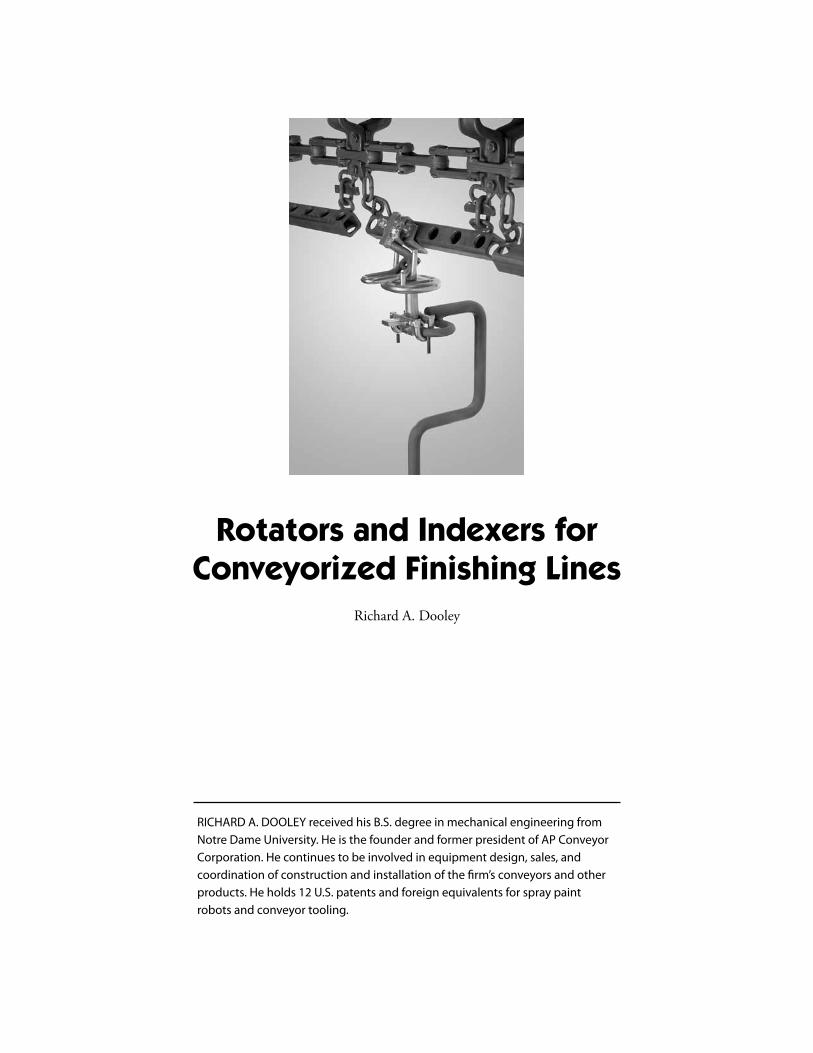
Rotators and Indexers for Conveyorized Finishing Lines
Richard A. Dooley
RICHARD A. DOOLEY received his B.S. degree in mechanical engineering from Notre Dame University. He is the founder and former president of AP Conveyor Corporation. He continues to be involved in equipment design, sales, and coordination of construction and installation of the firm’s conveyors and other products. He holds 12 U.S. patents and foreign equivalents for spray paint robots and conveyor tooling.
2
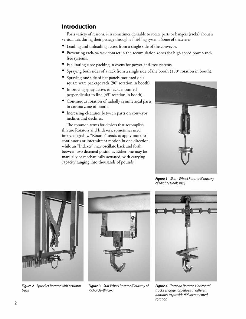
Introduction For a variety of reasons, it is sometimes desirable to rotate parts or hangers (racks) about a vertical axis during their passage through a finishing system. Some of these are:
• Loading and unloading access from a single side of the conveyor.• Preventing rack-to-rack contact in the accumulation zones for high speed power-and-
free systems.• Facilitating close packing in ovens for power-and-free systems.• Spraying both sides of a rack from a single side of the booth (180° rotation in booth).• Spraying one side of flat panels mounted on a
square ware package rack (90° rotation in booth).• Improving spray access to racks mounted
perpendicular to line (45° rotation in booth).• Continuous rotation of radially symmetrical parts
in corona zone of booth.• Increasing clearance between parts on conveyor
inclines and declines. The common terms for devices that accomplish this are Rotators and Indexers, sometimes used interchangeably. “Rotator” tends to apply more to continuous or intermittent motion in one direction, while an “Indexer” may oscillate back and forth between two detented positions. Either one may be manually or mechanically actuated, with carrying capacity ranging into thousands of pounds.
Figure 1 – Skate Wheel Rotator (Courtesy of Mighty Hook, Inc.)
Figure 2 – Sprocket Rotator with actuator track
Figure 3 – Star Wheel Rotator (Courtesy of Richards–Wilcox)
Figure 4 – Torpedo Rotator. Horizontal tracks engage torpedoes at different altitudes to provide 90° incremented rotation
3
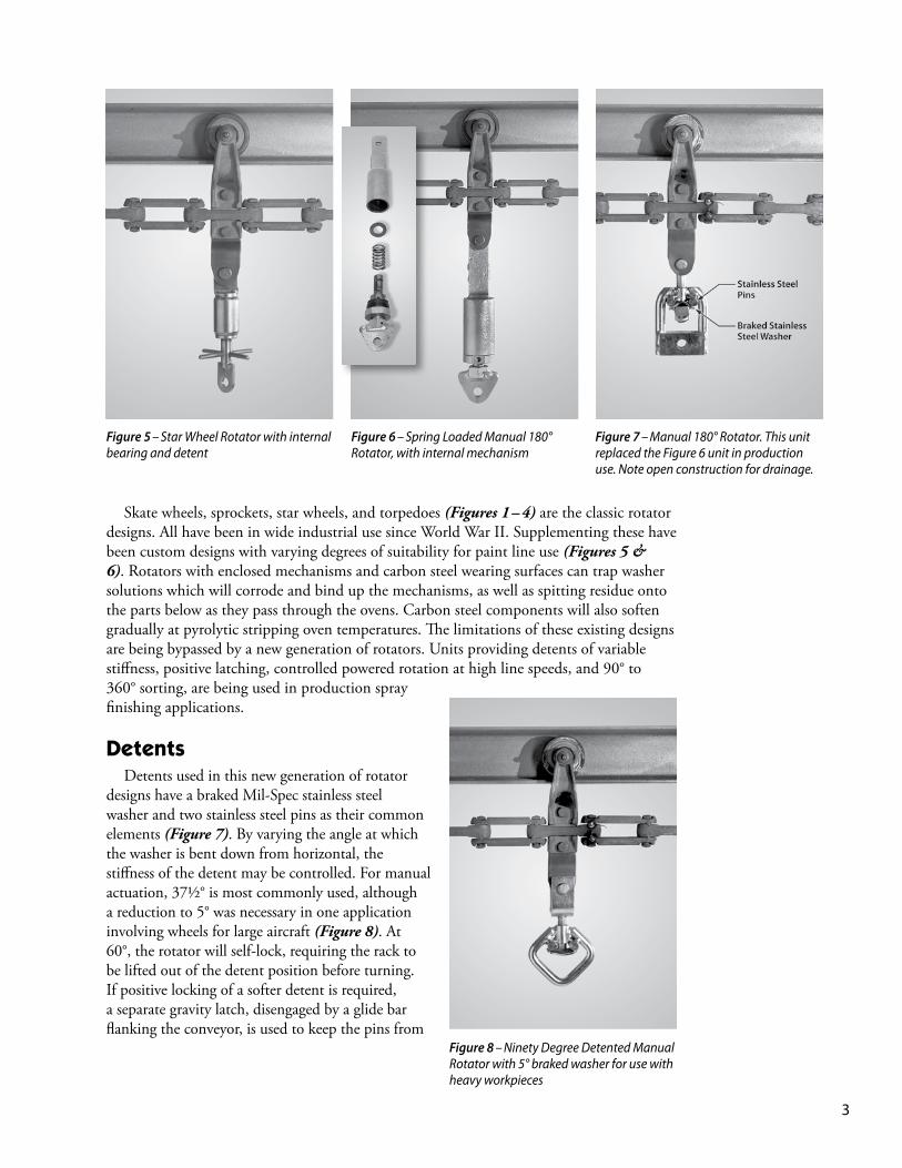
Skate wheels, sprockets, star wheels, and torpedoes (Figures 1 – 4) are the classic rotator designs. All have been in wide industrial use since World War II. Supplementing these have been custom designs with varying degrees of suitability for paint line use (Figures 5 & 6). Rotators with enclosed mechanisms and carbon steel wearing surfaces can trap washer solutions which will corrode and bind up the mechanisms, as well as spitting residue onto the parts below as they pass through the ovens. Carbon steel components will also soften gradually at pyrolytic stripping oven temperatures. The limitations of these existing designs are being bypassed by a new generation of rotators. Units providing detents of variable stiffness, positive latching, controlled powered rotation at high line speeds, and 90° to 360° sorting, are being used in production spray finishing applications.
Detents Detents used in this new generation of rotator designs have a braked Mil-Spec stainless steel washer and two stainless steel pins as their common elements (Figure 7). By varying the angle at which the washer is bent down from horizontal, the stiffness of the detent may be controlled. For manual actuation, 37½° is most commonly used, although a reduction to 5° was necessary in one application involving wheels for large aircraft (Figure 8). At 60°, the rotator will self-lock, requiring the rack to be lifted out of the detent position before turning. If positive locking of a softer detent is required, a separate gravity latch, disengaged by a glide bar flanking the conveyor, is used to keep the pins from
Figure 5 – Star Wheel Rotator with internal bearing and detent
Figure 7 – Manual 180° Rotator. This unit replaced the Figure 6 unit in production use. Note open construction for drainage.
Figure 8 – Ninety Degree Detented Manual Rotator with 5° braked washer for use with heavy workpieces
Figure 6 – Spring Loaded Manual 180° Rotator, with internal mechanism
4
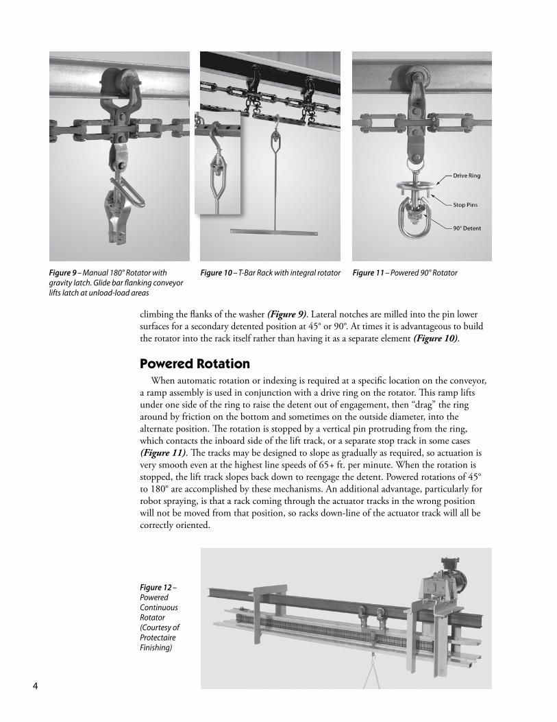
climbing the flanks of the washer (Figure 9). Lateral notches are milled into the pin lower surfaces for a secondary detented position at 45° or 90°. At times it is advantageous to build the rotator into the rack itself rather than having it as a separate element (Figure 10).
Powered Rotation When automatic rotation or indexing is required at a specific location on the conveyor, a ramp assembly is used in conjunction with a drive ring on the rotator. This ramp lifts under one side of the ring to raise the detent out of engagement, then “drag” the ring around by friction on the bottom and sometimes on the outside diameter, into the alternate position. The rotation is stopped by a vertical pin protruding from the ring, which contacts the inboard side of the lift track, or a separate stop track in some cases (Figure 11). The tracks may be designed to slope as gradually as required, so actuation is very smooth even at the highest line speeds of 65 + ft. per minute. When the rotation is stopped, the lift track slopes back down to reengage the detent. Powered rotations of 45° to 180° are accomplished by these mechanisms. An additional advantage, particularly for robot spraying, is that a rack coming through the actuator tracks in the wrong position will not be moved from that position, so racks down-line of the actuator track will all be correctly oriented.
Figure 11 – Powered 90° Rotator
Figure 12 – Powered Continuous Rotator (Courtesy of Protectaire Finishing)
Figure 10 – T-Bar Rack with integral rotator Figure 9 – Manual 180° Rotator with gravity latch. Glide bar flanking conveyor lifts latch at unload-load areas
5
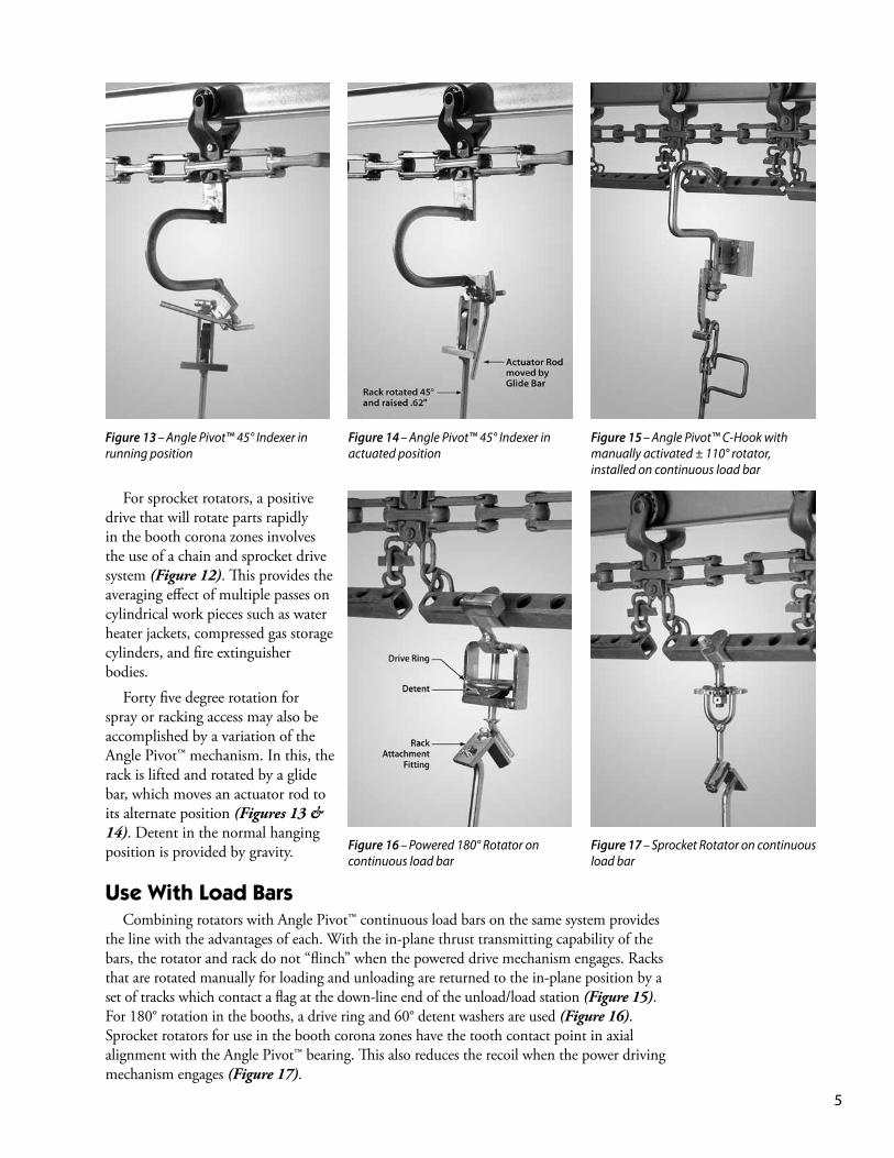
For sprocket rotators, a positive drive that will rotate parts rapidly in the booth corona zones involves the use of a chain and sprocket drive system (Figure 12). This provides the averaging effect of multiple passes on cylindrical work pieces such as water heater jackets, compressed gas storage cylinders, and fire extinguisher bodies.
Forty five degree rotation for spray or racking access may also be accomplished by a variation of the Angle Pivot™ mechanism. In this, the rack is lifted and rotated by a glide bar, which moves an actuator rod to its alternate position (Figures 13 & 14). Detent in the normal hanging position is provided by gravity.
Use With Load Bars Combining rotators with Angle Pivot™ continuous load bars on the same system provides the line with the advantages of each. With the in-plane thrust transmitting capability of the bars, the rotator and rack do not “flinch” when the powered drive mechanism engages. Racks that are rotated manually for loading and unloading are returned to the in-plane position by a set of tracks which contact a flag at the down-line end of the unload/load station (Figure 15). For 180° rotation in the booths, a drive ring and 60° detent washers are used (Figure 16). Sprocket rotators for use in the booth corona zones have the tooth contact point in axial alignment with the Angle Pivot™ bearing. This also reduces the recoil when the power driving mechanism engages (Figure 17).
Figure 13 – Angle Pivot™ 45° Indexer in running position
Figure 14 – Angle Pivot™ 45° Indexer in actuated position
Figure 15 – Angle Pivot™ C-Hook with manually activated ± 110° rotator, installed on continuous load bar
Figure 16 – Powered 180° Rotator on continuous load bar
Figure 17 – Sprocket Rotator on continuous load bar
6
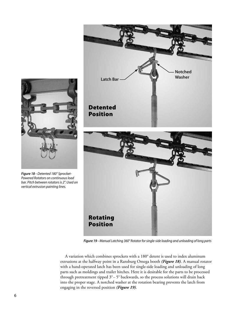
A variation which combines sprockets with a 180° detent is used to index aluminum extrusions at the halfway point in a Ransburg Omega booth (Figure 18). A manual rotator with a hand-operated latch has been used for single-side loading and unloading of long parts such as moldings and trailer hitches. Here it is desirable for the parts to be processed through pretreatment tipped 3° – 5° backwards, so the process solutions will drain back into the proper stage. A notched washer at the rotation bearing prevents the latch from engaging in the reversed position (Figure 19).
Figure 19 – Manual Latching 360° Rotator for single-side loading and unloading of long parts
Figure 18 – Detented 180° Sprocket-Powered Rotators on continuous load bar. Pitch between rotators is 2". Used on vertical extrusion painting lines.
7
Figure 21 – Actuator Track Assembly for Figure 20 rotator, friction driven from conveyor chain
Figure 22 – Actuator Track Assembly in retracted position
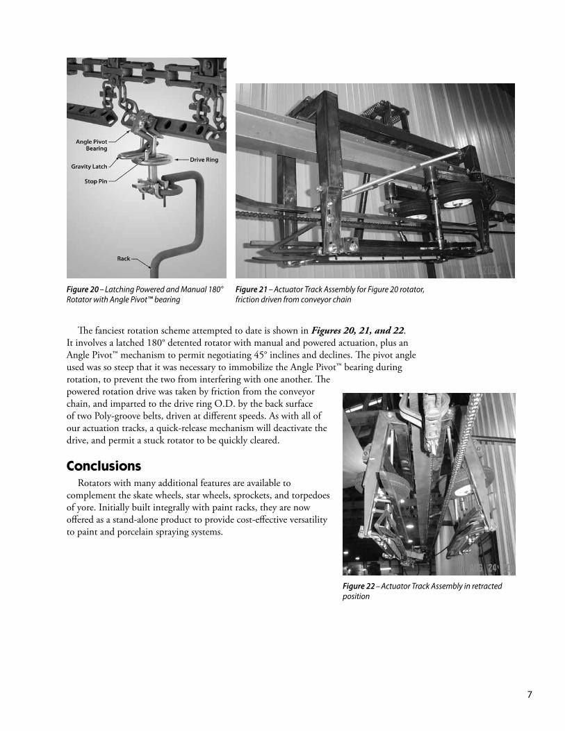
Figure 20 – Latching Powered and Manual 180° Rotator with Angle Pivot™ bearing
The fanciest rotation scheme attempted to date is shown in Figures 20, 21, and 22. It involves a latched 180° detented rotator with manual and powered actuation, plus an Angle Pivot™ mechanism to permit negotiating 45° inclines and declines. The pivot angle used was so steep that it was necessary to immobilize the Angle Pivot™ bearing during rotation, to prevent the two from interfering with one another. The powered rotation drive was taken by friction from the conveyor chain, and imparted to the drive ring O.D. by the back surface of two Poly-groove belts, driven at different speeds. As with all of our actuation tracks, a quick-release mechanism will deactivate the drive, and permit a stuck rotator to be quickly cleared.
Conclusions Rotators with many additional features are available to complement the skate wheels, star wheels, sprockets, and torpedoes of yore. Initially built integrally with paint racks, they are now offered as a stand-alone product to provide cost-effective versatility to paint and porcelain spraying systems.

8
1017 N. Cicero Ave.Chicago, IL 60651 USA Phone: 773-378-1909 Fax: 773-378-2083 Email: [email protected]
A Division of


![Rockers, Rotators and Shakers [ES]](https://img.pdfslide.us/doc/110x75/589d9b9b1a28abef498bc862/rockers-rotators-and-shakers-es.jpg)