Embed Size (px)
Citation preview
ArchiCAD NOTES
PRODUCE 2D ARCHITECTURAL DRAWINGS USING CAD SOFTWARE
SIN: 27957
Semester 2, 2010
Created: K.Berry, November 2007 F04A7 © Central TAFE 2008 Revised: V.Catalano, 1 July 2009 BDCAD402A Produce technical drawings to architectural conventions using CAD software page 1
Table of Contents
ArchiCAD Introduction ………………………………...……………………… 1
The ArchiCAD User Interface………………….……………………………… 2
Guidelines.........…………………………………………………………………. 6
Drawing Techniques ……………………………………….………………….. 9
Editing Techniques ……………………………………….………………….. 14
Parameter Transfer …………………….……………………………………… 20
Project Preferences ……………………………………………………………. 21
Wall Tool ……………………………..………………………………………….. 23
Parametric Objects ……………………………..……………………………… 25
Slab Tool…………………………………………………………………………. 30
Roof Tool ………………………………………………………………………... 33
Text ..……………………………………………………………………………… 38
Dimensioning………….……………………………………………………....... 38
Navigator Project Map ………………………………………………………… 58
Layers ….………………………………………………………………………… 62
Created: K.Berry, November 2007 F04A7 © Central TAFE 2008 Revised: V.Catalano, 1 July 2009 BDCAD402A Produce technical drawings to architectural conventions using CAD software page 1
ArchiCAD INTRODUCTION STARTING THE COMPUTER
• Turn the computer on.
• Hold down CTRL and ALT key and press the DELETE key
• When the dialogue box appears asking for a user name and password, enter the User Name and Password on your enrolment form. • Note: change your password at next login STARTING ArchiCAD Select the ArchiCAD icon from the desktop
Archicad.lnk
ArchiCAD
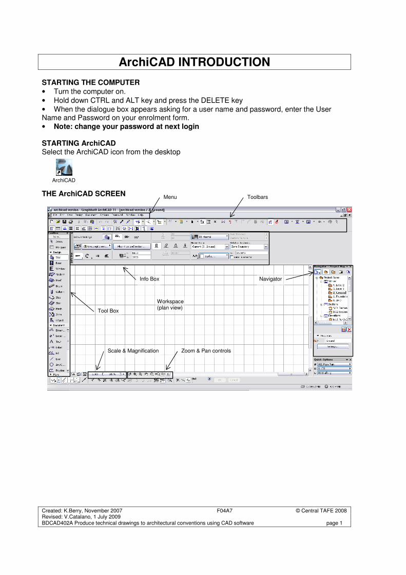
THE ArchiCAD SCREEN
Workspace (plan view)
Navigator
Zoom & Pan controls Scale & Magnification
Info Box
Menu
Tool Box
Toolbars
Created: K.Berry, November 2007 F04A7 © Central TAFE 2008 Revised: V.Catalano, 1 July 2009 BDCAD402A Produce technical drawings to architectural conventions using CAD software page 2
The ArchiCAD User Interface
Menus The menu bar displays pull down menus with related commands grouped under a main heading Some are specific to ArchiCAD and others common to other programs including Word and Excel.
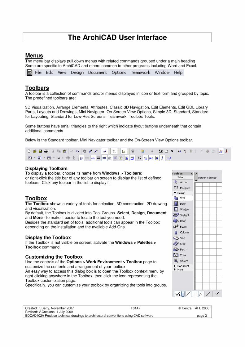
Toolbars A toolbar is a collection of commands and/or menus displayed in icon or text form and grouped by topic. The predefined toolbars are: 3D Visualization, Arrange Elements, Attributes, Classic 3D Navigation, Edit Elements, Edit GDL Library Parts, Layouts and Drawings, Mini Navigator, On-Screen View Options, Simple 3D, Standard, Standard for Layouting, Standard for Low-Res Screens, Teamwork, Toolbox Tools.
Some buttons have small triangles to the right which indicate flyout buttons underneath that contain additional commands Below is the Standard toolbar, Mini Navigator toolbar and the On-Screen View Options toolbar.
Displaying Toolbars To display a toolbar, choose its name from Windows > Toolbars;
or right-click the title bar of any toolbar on screen to display the list of defined toolbars. Click any toolbar in the list to display it.
Toolbox The Toolbox shows a variety of tools for selection, 3D construction, 2D drawing and visualization. By default, the Toolbox is divided into Tool Groups -Select, Design, Document and More - to make it easier to locate the tool you need. Besides the standard set of tools, additional tools can appear in the Toolbox depending on the installation and the available Add-Ons.
Display the Toolbox If the Toolbox is not visible on screen, activate the Windows > Palettes > Toolbox command.
Customizing the Toolbox Use the controls of the Options > Work Environment > Toolbox page to
customize the contents and arrangement of your toolbox. An easy way to access this dialog box is to open the Toolbox context menu by right-clicking anywhere in the Toolbox, then click the icon representing the Toolbox customization page: Specifically, you can customize your toolbox by organizing the tools into groups.
Created: K.Berry, November 2007 F04A7 © Central TAFE 2008 Revised: V.Catalano, 1 July 2009 BDCAD402A Produce technical drawings to architectural conventions using CAD software page 3
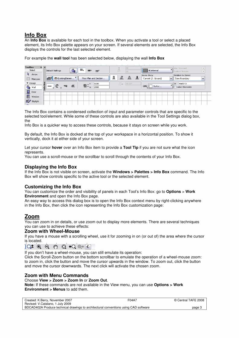
Info Box An Info Box is available for each tool in the toolbox. When you activate a tool or select a placed
element, its Info Box palette appears on your screen. If several elements are selected, the Info Box displays the controls for the last selected element. For example the wall tool has been selected below, displaying the wall Info Box
The Info Box contains a condensed collection of input and parameter controls that are specific to the selected tool/element. While some of these controls are also available in the Tool Settings dialog box, the Info Box is a quicker way to access these controls, because it stays on screen while you work. By default, the Info Box is docked at the top of your workspace in a horizontal position. To show it vertically, dock it at either side of your screen. Let your cursor hover over an Info Box item to provide a Tool Tip if you are not sure what the icon
represents. You can use a scroll-mouse or the scrollbar to scroll through the contents of your Info Box.
Displaying the Info Box If the Info Box is not visible on screen, activate the Windows > Palettes > Info Box command. The Info Box will show controls specific to the active tool or the selected element.
Customizing the Info Box You can customize the order and visibility of panels in each Tool’s Info Box: go to Options > Work Environment and open the Info Box page. An easy way to access this dialog box is to open the Info Box context menu by right-clicking anywhere in the Info Box, then click the icon representing the Info Box customization page:
Zoom You can zoom in on details, or use zoom out to display more elements. There are several techniques you can use to achieve these effects:
Zoom with Wheel-Mouse If you have a mouse with a scrolling wheel, use it for zooming in on (or out of) the area where the cursor is located.
If you don’t have a wheel-mouse, you can still emulate its operation: Click the Scroll-Zoom button on the bottom scrollbar to emulate the operation of a wheel-mouse zoom: to zoom in, click the button and move the cursor upwards in the window. To zoom out, click the button and move the cursor downwards. The next click will activate the chosen zoom.
Zoom with Menu Commands Choose View > Zoom > Zoom In or Zoom Out. Note: If these commands are not available in the View menu, you can use Options > Work Environment > Menus to add them.
Created: K.Berry, November 2007 F04A7 © Central TAFE 2008 Revised: V.Catalano, 1 July 2009 BDCAD402A Produce technical drawings to architectural conventions using CAD software page 4
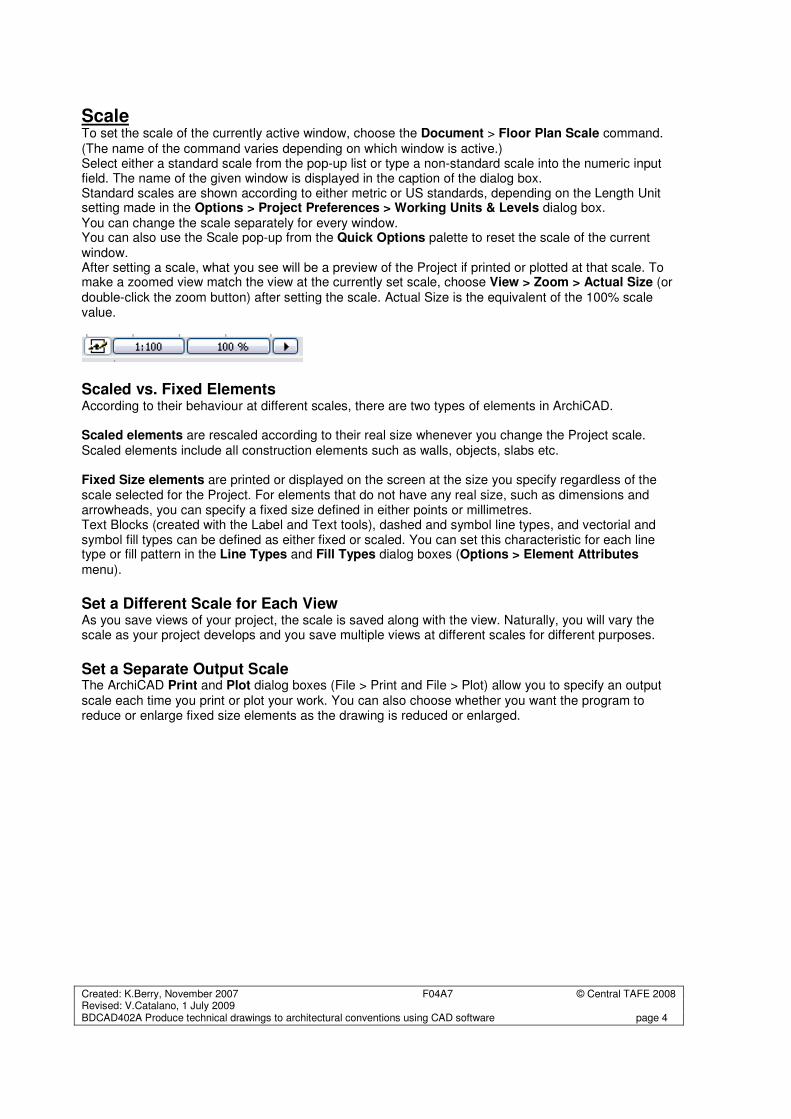
Scale To set the scale of the currently active window, choose the Document > Floor Plan Scale command.
(The name of the command varies depending on which window is active.) Select either a standard scale from the pop-up list or type a non-standard scale into the numeric input field. The name of the given window is displayed in the caption of the dialog box. Standard scales are shown according to either metric or US standards, depending on the Length Unit setting made in the Options > Project Preferences > Working Units & Levels dialog box. You can change the scale separately for every window. You can also use the Scale pop-up from the Quick Options palette to reset the scale of the current window. After setting a scale, what you see will be a preview of the Project if printed or plotted at that scale. To make a zoomed view match the view at the currently set scale, choose View > Zoom > Actual Size (or double-click the zoom button) after setting the scale. Actual Size is the equivalent of the 100% scale value.
Scaled vs. Fixed Elements According to their behaviour at different scales, there are two types of elements in ArchiCAD. Scaled elements are rescaled according to their real size whenever you change the Project scale. Scaled elements include all construction elements such as walls, objects, slabs etc. Fixed Size elements are printed or displayed on the screen at the size you specify regardless of the scale selected for the Project. For elements that do not have any real size, such as dimensions and arrowheads, you can specify a fixed size defined in either points or millimetres. Text Blocks (created with the Label and Text tools), dashed and symbol line types, and vectorial and symbol fill types can be defined as either fixed or scaled. You can set this characteristic for each line type or fill pattern in the Line Types and Fill Types dialog boxes (Options > Element Attributes
menu).
Set a Different Scale for Each View As you save views of your project, the scale is saved along with the view. Naturally, you will vary the scale as your project develops and you save multiple views at different scales for different purposes.
Set a Separate Output Scale The ArchiCAD Print and Plot dialog boxes (File > Print and File > Plot) allow you to specify an output scale each time you print or plot your work. You can also choose whether you want the program to reduce or enlarge fixed size elements as the drawing is reduced or enlarged.
Created: K.Berry, November 2007 F04A7 © Central TAFE 2008 Revised: V.Catalano, 1 July 2009 BDCAD402A Produce technical drawings to architectural conventions using CAD software page 5
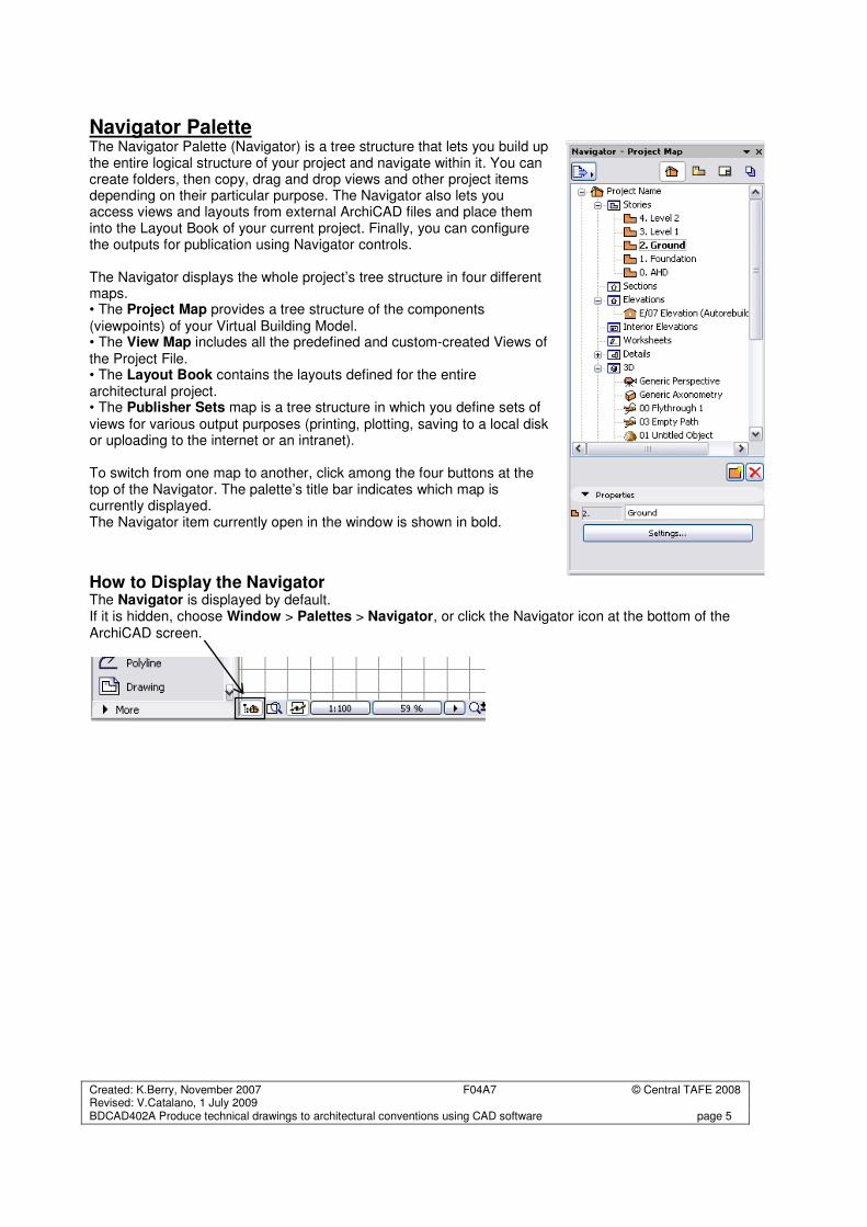
Navigator Palette The Navigator Palette (Navigator) is a tree structure that lets you build up the entire logical structure of your project and navigate within it. You can create folders, then copy, drag and drop views and other project items depending on their particular purpose. The Navigator also lets you access views and layouts from external ArchiCAD files and place them into the Layout Book of your current project. Finally, you can configure the outputs for publication using Navigator controls. The Navigator displays the whole project’s tree structure in four different maps. • The Project Map provides a tree structure of the components (viewpoints) of your Virtual Building Model. • The View Map includes all the predefined and custom-created Views of the Project File. • The Layout Book contains the layouts defined for the entire architectural project. • The Publisher Sets map is a tree structure in which you define sets of views for various output purposes (printing, plotting, saving to a local disk or uploading to the internet or an intranet). To switch from one map to another, click among the four buttons at the top of the Navigator. The palette’s title bar indicates which map is currently displayed. The Navigator item currently open in the window is shown in bold.
How to Display the Navigator The Navigator is displayed by default. If it is hidden, choose Window > Palettes > Navigator, or click the Navigator icon at the bottom of the ArchiCAD screen.
Created: K.Berry, November 2007 F04A7 © Central TAFE 2008 Revised: V.Catalano, 1 July 2009 BDCAD402A Produce technical drawings to architectural conventions using CAD software page 6
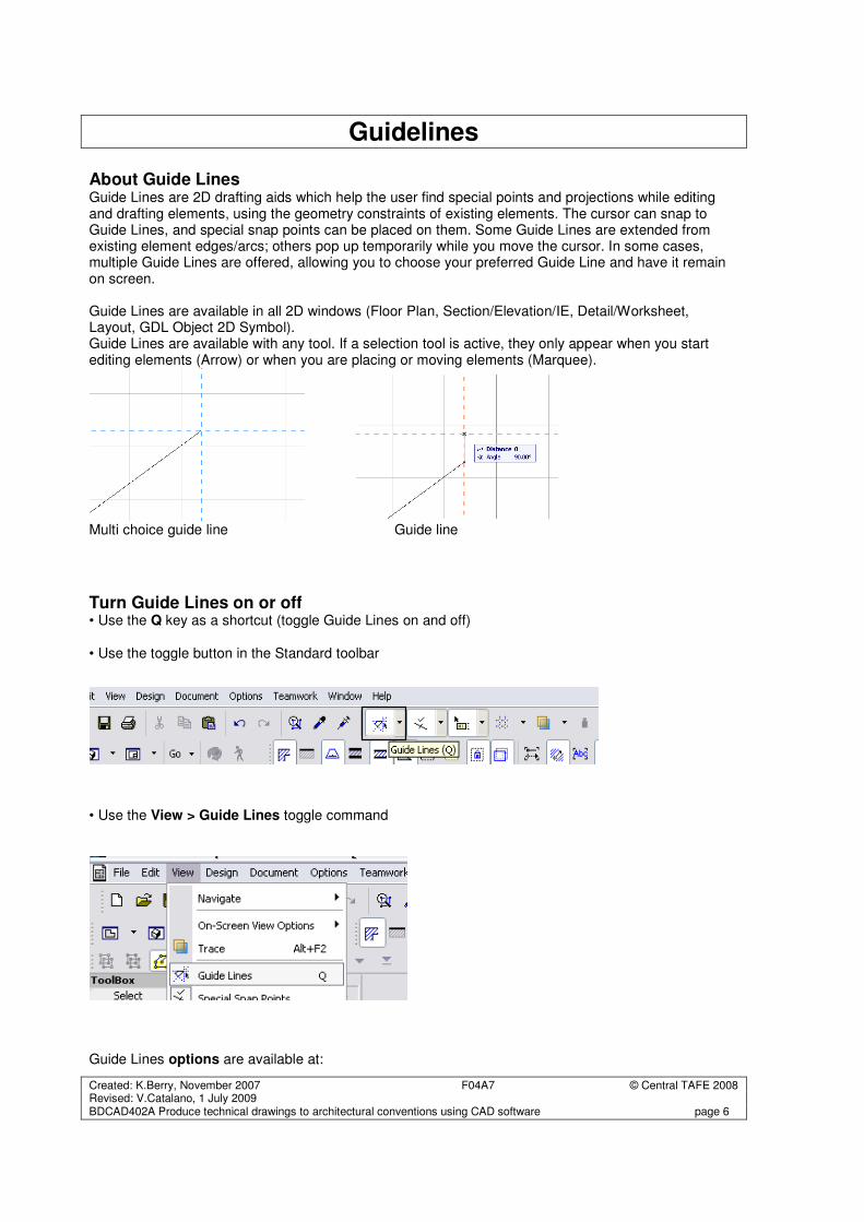
Guidelines About Guide Lines Guide Lines are 2D drafting aids which help the user find special points and projections while editing and drafting elements, using the geometry constraints of existing elements. The cursor can snap to Guide Lines, and special snap points can be placed on them. Some Guide Lines are extended from existing element edges/arcs; others pop up temporarily while you move the cursor. In some cases, multiple Guide Lines are offered, allowing you to choose your preferred Guide Line and have it remain on screen. Guide Lines are available in all 2D windows (Floor Plan, Section/Elevation/IE, Detail/Worksheet, Layout, GDL Object 2D Symbol). Guide Lines are available with any tool. If a selection tool is active, they only appear when you start editing elements (Arrow) or when you are placing or moving elements (Marquee).
Multi choice guide line Guide line
Turn Guide Lines on or off • Use the Q key as a shortcut (toggle Guide Lines on and off) • Use the toggle button in the Standard toolbar • Use the View > Guide Lines toggle command
Guide Lines options are available at:
Created: K.Berry, November 2007 F04A7 © Central TAFE 2008 Revised: V.Catalano, 1 July 2009 BDCAD402A Produce technical drawings to architectural conventions using CAD software page 7
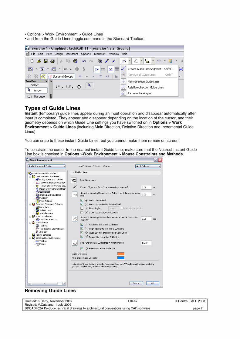
• Options > Work Environment > Guide Lines • and from the Guide Lines toggle command in the Standard Toolbar.
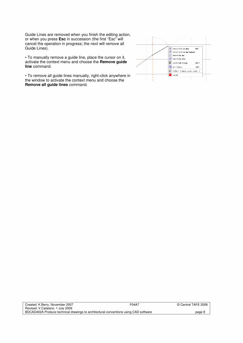
Types of Guide Lines Instant (temporary) guide lines appear during an input operation and disappear automatically after input is completed. They appear and disappear depending on the location of the cursor, and their geometry depends on which Guide Line settings you have switched on in Options > Work Environment > Guide Lines (including Main Direction, Relative Direction and Incremental Guide
Lines). You can snap to these instant Guide Lines, but you cannot make them remain on screen. To constrain the cursor to the nearest instant Guide Line, make sure that the Nearest Instant Guide Line box is checked in Options >Work Environment > Mouse Constraints and Methods.
Removing Guide Lines
Created: K.Berry, November 2007 F04A7 © Central TAFE 2008 Revised: V.Catalano, 1 July 2009 BDCAD402A Produce technical drawings to architectural conventions using CAD software page 8
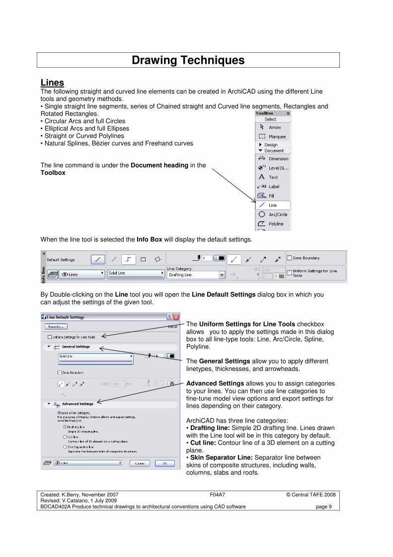
Guide Lines are removed when you finish the editing action, or when you press Esc in succession (the first “Esc” will cancel the operation in progress; the next will remove all Guide Lines). • To manually remove a guide line, place the cursor on it, activate the context menu and choose the Remove guide line command. • To remove all guide lines manually, right-click anywhere in the window to activate the context menu and choose the Remove all guide lines command.
Created: K.Berry, November 2007 F04A7 © Central TAFE 2008 Revised: V.Catalano, 1 July 2009 BDCAD402A Produce technical drawings to architectural conventions using CAD software page 9
Drawing Techniques
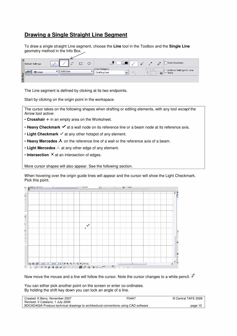
Lines The following straight and curved line elements can be created in ArchiCAD using the different Line tools and geometry methods. • Single straight line segments, series of Chained straight and Curved line segments, Rectangles and Rotated Rectangles. • Circular Arcs and full Circles • Elliptical Arcs and full Ellipses • Straight or Curved Polylines • Natural Splines, Bézier curves and Freehand curves The line command is under the Document heading in the Toolbox When the line tool is selected the Info Box will display the default settings.
By Double-clicking on the Line tool you will open the Line Default Settings dialog box in which you can adjust the settings of the given tool.
The Uniform Settings for Line Tools checkbox allows you to apply the settings made in this dialog box to all line-type tools: Line, Arc/Circle, Spline, Polyline. The General Settings allow you to apply different linetypes, thicknesses, and arrowheads. Advanced Settings allows you to assign categories to your lines. You can then use line categories to fine-tune model view options and export settings for lines depending on their category. ArchiCAD has three line categories: • Drafting line: Simple 2D drafting line. Lines drawn with the Line tool will be in this category by default. • Cut line: Contour line of a 3D element on a cutting plane. • Skin Separator Line: Separator line between skins of composite structures, including walls, columns, slabs and roofs.
Created: K.Berry, November 2007 F04A7 © Central TAFE 2008 Revised: V.Catalano, 1 July 2009 BDCAD402A Produce technical drawings to architectural conventions using CAD software page 10
Drawing a Single Straight Line Segment To draw a single straight Line segment, choose the Line tool in the Toolbox and the Single Line geometry method in the Info Box.
The Line segment is defined by clicking at its two endpoints. Start by clicking on the origin point in the workspace.
The cursor takes on the following shapes when drafting or editing elements, with any tool except the Arrow tool active:
• Crosshair + in an empty area on the Worksheet.
• Heavy Checkmark at a wall node on its reference line or a beam node at its reference axis.
• Light Checkmark at any other hotspot of any element.
• Heavy Mercedes on the reference line of a wall or the reference axis of a beam.
• Light Mercedes at any other edge of any element.
• Intersection at an intersection of edges.
More cursor shapes will also appear. See the following section.
When hovering over the origin guide lines will appear and the cursor will show the Light Checkmark. Pick this point.
Now move the mouse and a line will follow the cursor. Note the cursor changes to a white pencil. You can either pick another point on the screen or enter co-ordinates. By holding the shift key down you can lock an angle of a line.
Created: K.Berry, November 2007 F04A7 © Central TAFE 2008 Revised: V.Catalano, 1 July 2009 BDCAD402A Produce technical drawings to architectural conventions using CAD software page 11
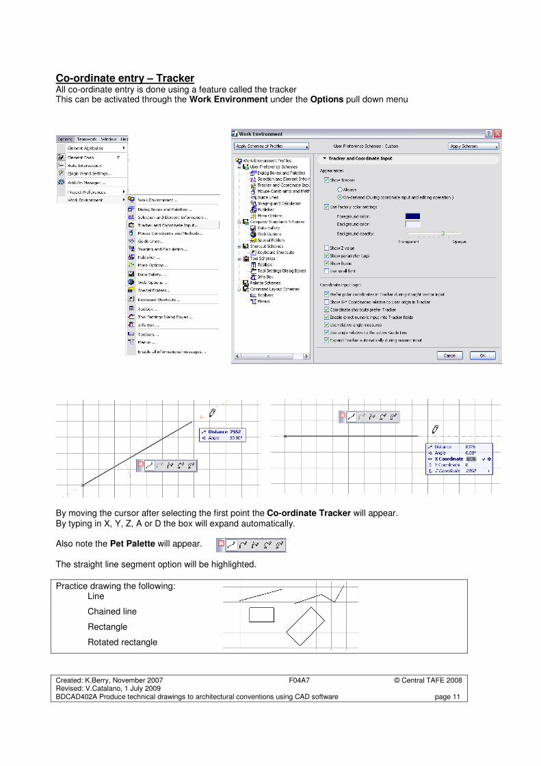
Co-ordinate entry – Tracker All co-ordinate entry is done using a feature called the tracker This can be activated through the Work Environment under the Options pull down menu
By moving the cursor after selecting the first point the Co-ordinate Tracker will appear. By typing in X, Y, Z, A or D the box will expand automatically. Also note the Pet Palette will appear. The straight line segment option will be highlighted.
Practice drawing the following: Line
Chained line
Rectangle
Rotated rectangle
Created: K.Berry, November 2007 F04A7 © Central TAFE 2008 Revised: V.Catalano, 1 July 2009 BDCAD402A Produce technical drawings to architectural conventions using CAD software page 12
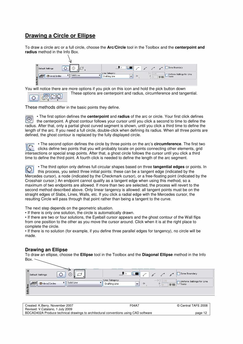
Drawing a Circle or Ellipse To draw a circle arc or a full circle, choose the Arc/Circle tool in the Toolbox and the centerpoint and radius method in the Info Box.
You will notice there are more options if you pick on this icon and hold the pick button down
These options are centerpoint and radius, circumference and tangential.
These methods differ in the basic points they define.
• The first option defines the centerpoint and radius of the arc or circle. Your first click defines
the centerpoint. A ghost contour follows your cursor until you click a second to time to define the radius. After that, only a partial ghost curved segment is shown, until you click a third time to define the length of the arc. If you need a full circle, double-click when defining its radius. When all three points are defined, the ghost contour is replaced by the fully displayed circle.
• The second option defines the circle by three points on the arc’s circumference. The first two clicks define two points that you will probably locate on points connecting other elements, grid
intersections or special snap points. After that, a ghost circle follows the cursor until you click a third time to define the third point. A fourth click is needed to define the length of the arc segment.
• The third option only defines full circular shapes based on three tangential edges or points. In
this process, you select three initial points: these can be a tangent edge (indicated by the Mercedes cursor), a node (indicated by the Checkmark cursor), or a free-floating point (indicated by the Crosshair cursor.) An endpoint cannot qualify as a tangent edge when using this method, so a maximum of two endpoints are allowed. If more than two are selected, the process will revert to the second method described above. Only linear tangency is allowed: all tangent points must be on the straight edges of Slabs, Lines, Walls, etc. If you click a radial edge with the Mercedes cursor, the resulting Circle will pass through that point rather than being a tangent to the curve. The next step depends on the geometric situation. • If there is only one solution, the circle is automatically drawn. • If there are two or four solutions, the Eyeball cursor appears and the ghost contour of the Wall flips from one position to the other as you move the cursor around. Click when it is at the right place to complete the circle. • If there is no solution (for example, if you define three parallel edges for tangency), no circle will be made.
Drawing an Ellipse To draw an ellipse, choose the Ellipse tool in the Toolbox and the Diagonal Ellipse method in the Info Box.
Created: K.Berry, November 2007 F04A7 © Central TAFE 2008 Revised: V.Catalano, 1 July 2009 BDCAD402A Produce technical drawings to architectural conventions using CAD software page 13
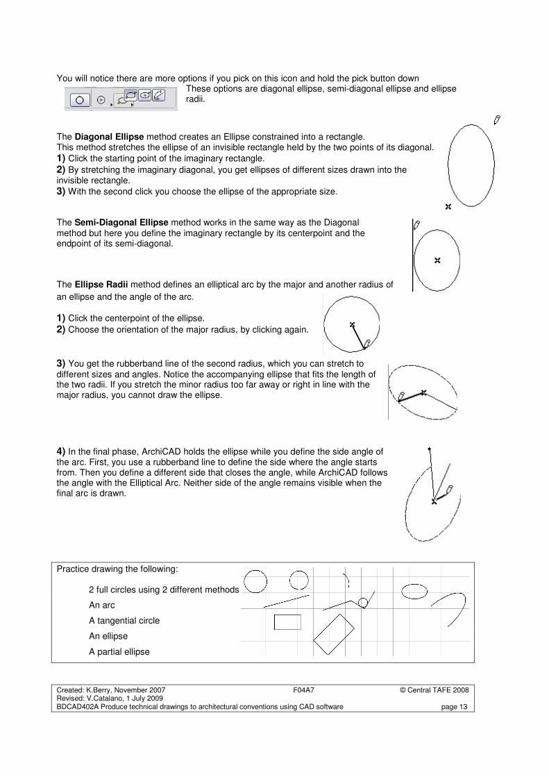
You will notice there are more options if you pick on this icon and hold the pick button down These options are diagonal ellipse, semi-diagonal ellipse and ellipse radii.
The Diagonal Ellipse method creates an Ellipse constrained into a rectangle. This method stretches the ellipse of an invisible rectangle held by the two points of its diagonal.
1) Click the starting point of the imaginary rectangle.
2) By stretching the imaginary diagonal, you get ellipses of different sizes drawn into the invisible rectangle.
3) With the second click you choose the ellipse of the appropriate size. The Semi-Diagonal Ellipse method works in the same way as the Diagonal
method but here you define the imaginary rectangle by its centerpoint and the endpoint of its semi-diagonal. The Ellipse Radii method defines an elliptical arc by the major and another radius of
an ellipse and the angle of the arc.
1) Click the centerpoint of the ellipse.
2) Choose the orientation of the major radius, by clicking again.
3) You get the rubberband line of the second radius, which you can stretch to
different sizes and angles. Notice the accompanying ellipse that fits the length of the two radii. If you stretch the minor radius too far away or right in line with the major radius, you cannot draw the ellipse. 4) In the final phase, ArchiCAD holds the ellipse while you define the side angle of the arc. First, you use a rubberband line to define the side where the angle starts from. Then you define a different side that closes the angle, while ArchiCAD follows the angle with the Elliptical Arc. Neither side of the angle remains visible when the final arc is drawn.
Practice drawing the following: 2 full circles using 2 different methods
An arc
A tangential circle
An ellipse
A partial ellipse
Created: K.Berry, November 2007 F04A7 © Central TAFE 2008 Revised: V.Catalano, 1 July 2009 BDCAD402A Produce technical drawings to architectural conventions using CAD software page 14
Editing Techniques
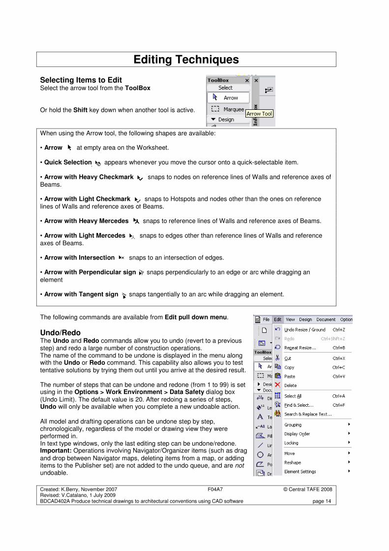
Selecting Items to Edit Select the arrow tool from the ToolBox Or hold the Shift key down when another tool is active.
When using the Arrow tool, the following shapes are available: • Arrow at empty area on the Worksheet. • Quick Selection appears whenever you move the cursor onto a quick-selectable item. • Arrow with Heavy Checkmark snaps to nodes on reference lines of Walls and reference axes of Beams. • Arrow with Light Checkmark snaps to Hotspots and nodes other than the ones on reference lines of Walls and reference axes of Beams. • Arrow with Heavy Mercedes snaps to reference lines of Walls and reference axes of Beams. • Arrow with Light Mercedes snaps to edges other than reference lines of Walls and reference
axes of Beams. • Arrow with Intersection snaps to an intersection of edges. • Arrow with Perpendicular sign snaps perpendicularly to an edge or arc while dragging an
element • Arrow with Tangent sign snaps tangentially to an arc while dragging an element.
The following commands are available from Edit pull down menu.
Undo/Redo The Undo and Redo commands allow you to undo (revert to a previous step) and redo a large number of construction operations. The name of the command to be undone is displayed in the menu along with the Undo or Redo command. This capability also allows you to test tentative solutions by trying them out until you arrive at the desired result. The number of steps that can be undone and redone (from 1 to 99) is set using in the Options > Work Environment > Data Safety dialog box (Undo Limit). The default value is 20. After redoing a series of steps, Undo will only be available when you complete a new undoable action. All model and drafting operations can be undone step by step, chronologically, regardless of the model or drawing view they were performed in. In text type windows, only the last editing step can be undone/redone. Important: Operations involving Navigator/Organizer items (such as drag
and drop between Navigator maps, deleting items from a map, or adding items to the Publisher set) are not added to the undo queue, and are not undoable.
Created: K.Berry, November 2007 F04A7 © Central TAFE 2008 Revised: V.Catalano, 1 July 2009 BDCAD402A Produce technical drawings to architectural conventions using CAD software page 15
Cut The Edit > Cut command removes selected elements from a Project and places them on the Clipboard for future use via the Paste command. It can also be used for dialog box or Coordinate Box numeric field contents. Note: The Cut command is not available in the 3D Window. The selection can be made with either the Arrow or the Marquee tool.
If you cut a construction element from a Model-type Section/Elevation/IE window, the element is also cut from the Floor Plan. In Text type windows, you can use the Cut command as in any word processor.
Copy The Edit > Copy command puts the selected construction or text elements on the Clipboard, but the
selected elements are not removed from the original document. The selection can be made with either the Arrow or the Marquee tool. Note: You cannot create new construction elements in Section/Elevation/IE windows using Copy/Paste.
(The only exception is if you use the “Drag a copy” command to move a Door/Window, in a model-type Section window.) In the 3D window, the Copy command is only available with the Marquee tool.
Paste Use Edit > Paste command to insert the contents of the Clipboard onto the current Project or a text
Window. When pasting cut elements into a Section/Elevation/IE or Detail/Worksheet window, the elements are pasted as drawing primitives (points, lines and fills). Note: You cannot create new construction elements in Section/Elevation/IE windows using either
Cut/Paste or Copy/Paste. The Paste command is not available in the 3D window. When you are pasting with a multiple story marquee, an alert appears asking you to identify the copied story to merge to the current one. If you Cut/Copy and then Paste a selection between stories at the same zoom level with no Panning operations in between, the contents of the Clipboard are pasted into the same position they were originally cut or copied from.
Delete The Edit > Delete command removes selected items from Project or text Windows. The deleted elements are not preserved on the Clipboard. They are easily retrieved by Undo. The keyboard equivalent of Delete is hitting the Backspace or Delete key. Deleting construction elements in any model window (Floor Plan, 3D, model-type Section/Elevation/IE) will also clear these elements from all the other windows. Note: Deleting any additional (i.e. manually added) elements from a model-type Section/Elevation/IE window or any elements from a drawing-type Section/Elevation/IE window will leave all other windows unchanged.
Created: K.Berry, November 2007 F04A7 © Central TAFE 2008 Revised: V.Catalano, 1 July 2009 BDCAD402A Produce technical drawings to architectural conventions using CAD software page 16
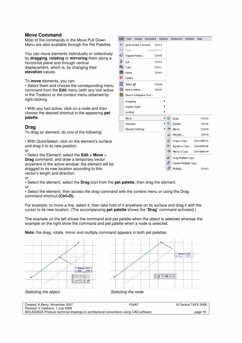
Move Command Most of the commands in the Move Pull Down Menu are also available through the Pet Palettes. You can move elements individually or collectively by dragging, rotating or mirroring them along a horizontal plane and through vertical displacement, which is, by changing their elevation values. To move elements, you can: • Select them and choose the corresponding menu command from the Edit menu (with any tool active in the Toolbox) or the context menu obtained by right-clicking. • With any tool active, click on a node and then choose the desired shortcut in the appearing pet palette.
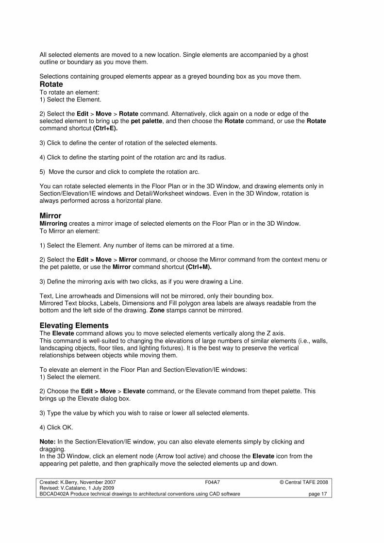
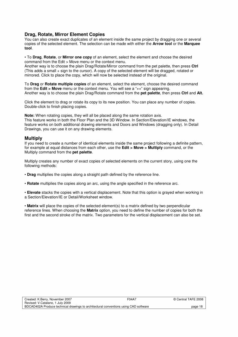
Drag To drag an element, do one of the following: • With QuickSelect: click on the element’s surface and drag it to its new position. or • Select the Element; select the Edit > Move > Drag command, and draw a temporary vector anywhere in the active window: the element will be dragged to its new location according to this vector’s length and direction. or • Select the element, select the Drag icon from the pet palette, then drag the element. or • Select the element, then access the drag command with the context menu or using the Drag command shortcut (Ctrl+D). For example: to move a line, select it, then take hold of it anywhere on its surface and drag it with the cursor to its new location. (The accompanying pet palette shows the “Drag” command activated.) The example on the left shows the command and pet palette when the object is selected whereas the example on the right show the command and pet palette when a node is selected. Note: the drag, rotate, mirror and multiply command appears in both pet palettes
Selecting the object Selecting the node
Created: K.Berry, November 2007 F04A7 © Central TAFE 2008 Revised: V.Catalano, 1 July 2009 BDCAD402A Produce technical drawings to architectural conventions using CAD software page 17
All selected elements are moved to a new location. Single elements are accompanied by a ghost outline or boundary as you move them. Selections containing grouped elements appear as a greyed bounding box as you move them.
Rotate To rotate an element: 1) Select the Element. 2) Select the Edit > Move > Rotate command. Alternatively, click again on a node or edge of the selected element to bring up the pet palette, and then choose the Rotate command, or use the Rotate command shortcut (Ctrl+E).
3) Click to define the center of rotation of the selected elements. 4) Click to define the starting point of the rotation arc and its radius. 5) Move the cursor and click to complete the rotation arc. You can rotate selected elements in the Floor Plan or in the 3D Window, and drawing elements only in Section/Elevation/IE windows and Detail/Worksheet windows. Even in the 3D Window, rotation is always performed across a horizontal plane.
Mirror Mirroring creates a mirror image of selected elements on the Floor Plan or in the 3D Window.
To Mirror an element: 1) Select the Element. Any number of items can be mirrored at a time. 2) Select the Edit > Move > Mirror command, or choose the Mirror command from the context menu or the pet palette, or use the Mirror command shortcut (Ctrl+M). 3) Define the mirroring axis with two clicks, as if you were drawing a Line. Text, Line arrowheads and Dimensions will not be mirrored, only their bounding box. Mirrored Text blocks, Labels, Dimensions and Fill polygon area labels are always readable from the bottom and the left side of the drawing. Zone stamps cannot be mirrored.
Elevating Elements The Elevate command allows you to move selected elements vertically along the Z axis.
This command is well-suited to changing the elevations of large numbers of similar elements (i.e., walls, landscaping objects, floor tiles, and lighting fixtures). It is the best way to preserve the vertical relationships between objects while moving them. To elevate an element in the Floor Plan and Section/Elevation/IE windows: 1) Select the element. 2) Choose the Edit > Move > Elevate command, or the Elevate command from thepet palette. This brings up the Elevate dialog box. 3) Type the value by which you wish to raise or lower all selected elements. 4) Click OK. Note: In the Section/Elevation/IE window, you can also elevate elements simply by clicking and dragging. In the 3D Window, click an element node (Arrow tool active) and choose the Elevate icon from the appearing pet palette, and then graphically move the selected elements up and down.
Created: K.Berry, November 2007 F04A7 © Central TAFE 2008 Revised: V.Catalano, 1 July 2009 BDCAD402A Produce technical drawings to architectural conventions using CAD software page 18
Drag, Rotate, Mirror Element Copies You can also create exact duplicates of an element inside the same project by dragging one or several copies of the selected element. The selection can be made with either the Arrow tool or the Marquee tool. • To Drag, Rotate, or Mirror one copy of an element, select the element and choose the desired command from the Edit > Move menu or the context menu. Another way is to choose the plain Drag/Rotate/Mirror command from the pet palette, then press Ctrl (This adds a small + sign to the cursor). A copy of the selected element will be dragged, rotated or mirrored. Click to place the copy, which will now be selected instead of the original. To Drag or Rotate multiple copies of an element, select the element, choose the desired command from the Edit > Move menu or the context menu. You will see a “++” sign appearing. Another way is to choose the plain Drag/Rotate command from the pet palette, then press Ctrl and Alt.
Click the element to drag or rotate its copy to its new position. You can place any number of copies. Double-click to finish placing copies. Note: When rotating copies, they will all be placed along the same rotation axis. This feature works in both the Floor Plan and the 3D Window. In Section/Elevation/IE windows, the feature works on both additional drawing elements and Doors and Windows (dragging only). In Detail Drawings, you can use it on any drawing elements.
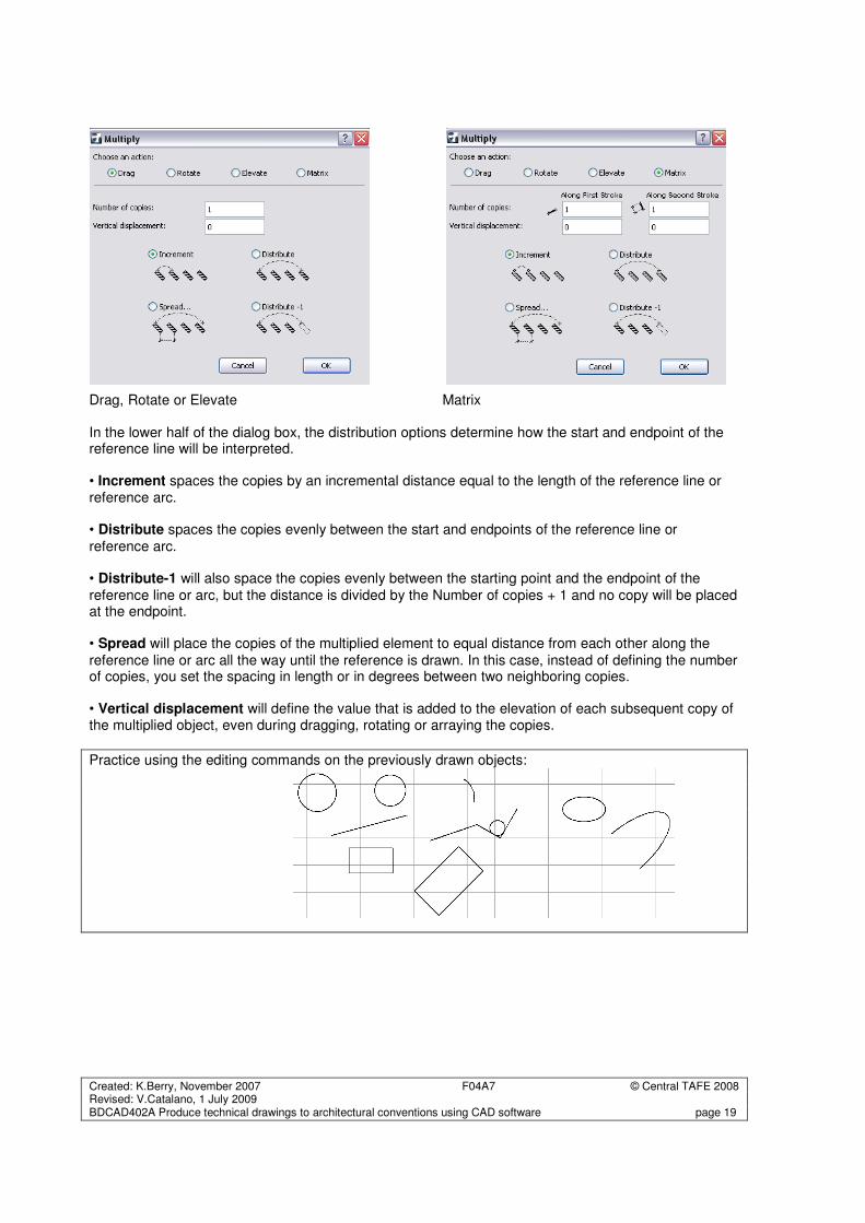
Multiply If you need to create a number of identical elements inside the same project following a definite pattern, for example at equal distances from each other, use the Edit > Move > Multiply command, or the Multiply command from the pet palette. Multiply creates any number of exact copies of selected elements on the current story, using one the following methods: • Drag multiplies the copies along a straight path defined by the reference line. • Rotate multiplies the copies along an arc, using the angle specified in the reference arc. • Elevate stacks the copies with a vertical displacement. Note that this option is grayed when working in a Section/Elevation/IE or Detail/Worksheet window. • Matrix will place the copies of the selected element(s) to a matrix defined by two perpendicular reference lines. When choosing the Matrix option, you need to define the number of copies for both the
first and the second stroke of the matrix. Two parameters for the vertical displacement can also be set.
Created: K.Berry, November 2007 F04A7 © Central TAFE 2008 Revised: V.Catalano, 1 July 2009 BDCAD402A Produce technical drawings to architectural conventions using CAD software page 19
Drag, Rotate or Elevate Matrix In the lower half of the dialog box, the distribution options determine how the start and endpoint of the reference line will be interpreted. • Increment spaces the copies by an incremental distance equal to the length of the reference line or reference arc. • Distribute spaces the copies evenly between the start and endpoints of the reference line or
reference arc. • Distribute-1 will also space the copies evenly between the starting point and the endpoint of the
reference line or arc, but the distance is divided by the Number of copies + 1 and no copy will be placed at the endpoint. • Spread will place the copies of the multiplied element to equal distance from each other along the
reference line or arc all the way until the reference is drawn. In this case, instead of defining the number of copies, you set the spacing in length or in degrees between two neighboring copies. • Vertical displacement will define the value that is added to the elevation of each subsequent copy of the multiplied object, even during dragging, rotating or arraying the copies.
Practice using the editing commands on the previously drawn objects:
Created: K.Berry, November 2007 F04A7 © Central TAFE 2008 Revised: V.Catalano, 1 July 2009 BDCAD402A Produce technical drawings to architectural conventions using CAD software page 20
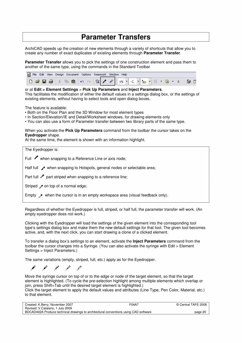
Parameter Transfers ArchiCAD speeds up the creation of new elements through a variety of shortcuts that allow you to create any number of exact duplicates of existing elements through Parameter Transfer. Parameter Transfer allows you to pick the settings of one construction element and pass them to another of the same type, using the commands in the Standard Toolbar
or at Edit > Element Settings > Pick Up Parameters and Inject Parameters. This facilitates the modification of either the default values in a settings dialog box, or the settings of existing elements, without having to select tools and open dialog boxes. The feature is available: • Both on the Floor Plan and the 3D Window for most element types • In Section/Elevation/IE and Detail/Worksheet windows, for drawing elements only • You can also use a form of Parameter transfer between two library parts of the same type. When you activate the Pick Up Parameters command from the toolbar the cursor takes on the Eyedropper shape. At the same time, the element is shown with an information highlight.
The Eyedropper is: Full when snapping to a Reference Line or axis node; Half full when snapping to Hotspots, general nodes or selectable area; Part full part striped when snapping to a reference line; Striped on top of a normal edge; Empty when the cursor is in an empty workspace area (visual feedback only).
Regardless of whether the Eyedropper is full, striped, or half full, the parameter transfer will work. (An empty eyedropper does not work.) Clicking with the Eyedropper will load the settings of the given element into the corresponding tool type’s settings dialog box and make them the new default settings for that tool. The given tool becomes active, and, with the next click, you can start drawing a clone of a clicked element. To transfer a dialog box’s settings to an element, activate the Inject Parameters command from the
toolbar the cursor changes into a Syringe. (You can also activate the syringe with Edit > Element Settings > Inject Parameters.) The same variations (empty, striped, full, etc.) apply as for the Eyedropper.
Move the syringe cursor on top of or to the edge or node of the target element, so that the target element is highlighted. (To cycle the pre-selection highlight among multiple elements which overlap or join, press Shift+Tab until the desired target element is highlighted.) Click the target element to apply the default values and attributes (Line Type, Pen Color, Material, etc.) to that element.
Created: K.Berry, November 2007 F04A7 © Central TAFE 2008 Revised: V.Catalano, 1 July 2009 BDCAD402A Produce technical drawings to architectural conventions using CAD software page 21
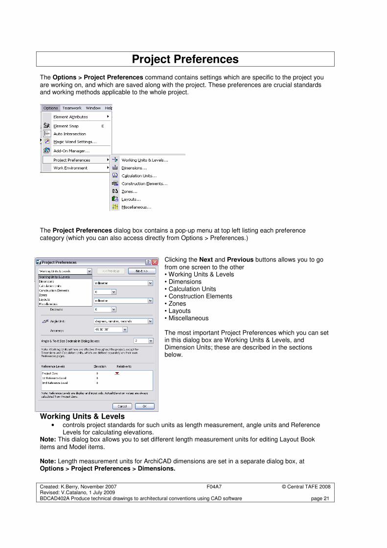
Project Preferences The Options > Project Preferences command contains settings which are specific to the project you
are working on, and which are saved along with the project. These preferences are crucial standards and working methods applicable to the whole project. The Project Preferences dialog box contains a pop-up menu at top left listing each preference category (which you can also access directly from Options > Preferences.)
Clicking the Next and Previous buttons allows you to go
from one screen to the other • Working Units & Levels • Dimensions • Calculation Units • Construction Elements • Zones • Layouts • Miscellaneous The most important Project Preferences which you can set in this dialog box are Working Units & Levels, and Dimension Units; these are described in the sections below.
Working Units & Levels • controls project standards for such units as length measurement, angle units and Reference
Levels for calculating elevations. Note: This dialog box allows you to set different length measurement units for editing Layout Book
items and Model items. Note: Length measurement units for ArchiCAD dimensions are set in a separate dialog box, at Options > Project Preferences > Dimensions.
Created: K.Berry, November 2007 F04A7 © Central TAFE 2008 Revised: V.Catalano, 1 July 2009 BDCAD402A Produce technical drawings to architectural conventions using CAD software page 22
Dimension Units To set dimension unit preferences for the current project, open Options > Project Preferences > Dimensions. Each project can be assigned its own Dimensioning Standard. These are predefined sets of units that affect the entire project at a single click. This is useful if you are working on several projects requiring different levels of accuracy (construction details versus site plans) However, you can fine-tune any of the dimension unit types in the project. For example, if you are working with the millimeter standard, but decide to display Door/Window dimensions in centimeters, choose Door/Window as the dimension type and change its units to centimeters. The project Standard is now “Custom.” You can save this new standard under its own name by clicking “Add.” Dimension unit standards you set here are saved along with your project. While the Dimension Standard set here applies to the Project globally, you can apply a different dimension standard to any view of the Project, if needed. To change the dimension standard for any single view, open its View Settings and adjust its Dimensions setting.
Calculation Units
• controls the settings for length, area, volume and angle units.
Construction Elements • controls the linetypes of the construction elements for storey above and/or below the current
storey.
• controls the 3D intersection priorities.
Zones • sets the areas and objects to be calculated within the zones.
Layouts • controls the display of the layouts.
Created: K.Berry, November 2007 F04A7 © Central TAFE 2008 Revised: V.Catalano, 1 July 2009 BDCAD402A Produce technical drawings to architectural conventions using CAD software page 23
Wall Tool
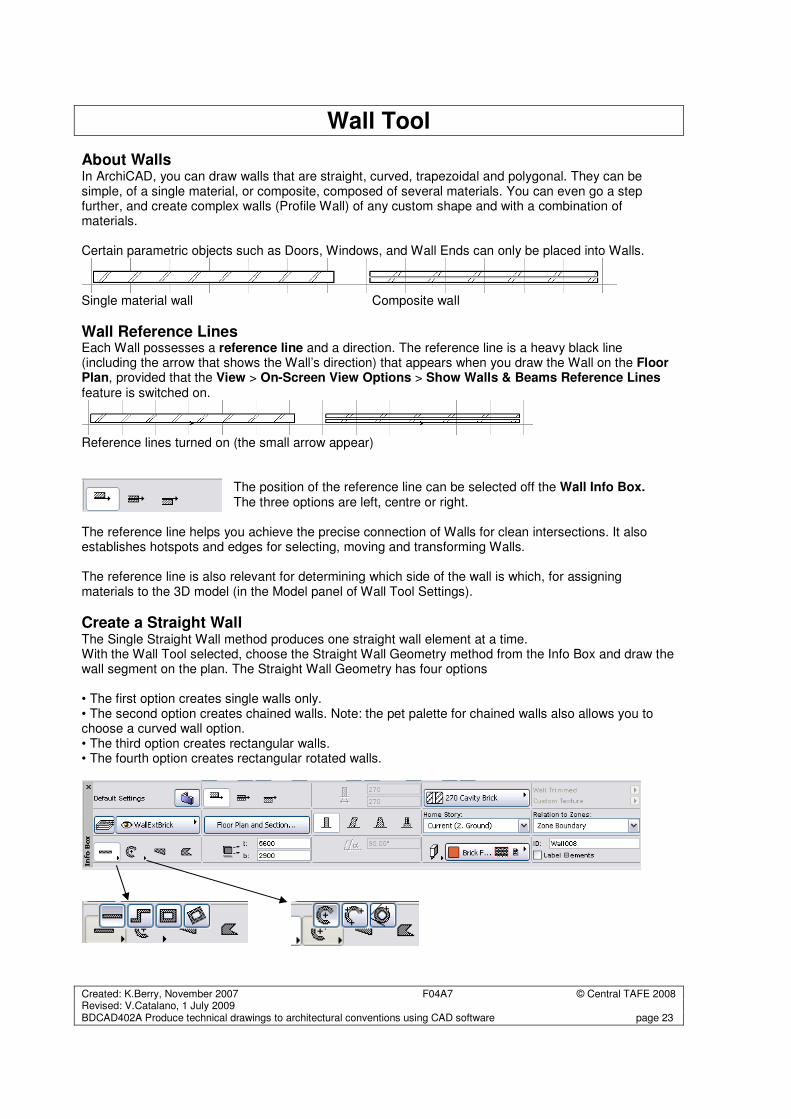
About Walls In ArchiCAD, you can draw walls that are straight, curved, trapezoidal and polygonal. They can be simple, of a single material, or composite, composed of several materials. You can even go a step further, and create complex walls (Profile Wall) of any custom shape and with a combination of materials. Certain parametric objects such as Doors, Windows, and Wall Ends can only be placed into Walls.
Single material wall Composite wall
Wall Reference Lines Each Wall possesses a reference line and a direction. The reference line is a heavy black line (including the arrow that shows the Wall’s direction) that appears when you draw the Wall on the Floor Plan, provided that the View > On-Screen View Options > Show Walls & Beams Reference Lines feature is switched on.
Reference lines turned on (the small arrow appear)
The position of the reference line can be selected off the Wall Info Box. The three options are left, centre or right.
The reference line helps you achieve the precise connection of Walls for clean intersections. It also establishes hotspots and edges for selecting, moving and transforming Walls. The reference line is also relevant for determining which side of the wall is which, for assigning materials to the 3D model (in the Model panel of Wall Tool Settings).
Create a Straight Wall The Single Straight Wall method produces one straight wall element at a time. With the Wall Tool selected, choose the Straight Wall Geometry method from the Info Box and draw the wall segment on the plan. The Straight Wall Geometry has four options • The first option creates single walls only. • The second option creates chained walls. Note: the pet palette for chained walls also allows you to choose a curved wall option. • The third option creates rectangular walls. • The fourth option creates rectangular rotated walls.
Created: K.Berry, November 2007 F04A7 © Central TAFE 2008 Revised: V.Catalano, 1 July 2009 BDCAD402A Produce technical drawings to architectural conventions using CAD software page 24
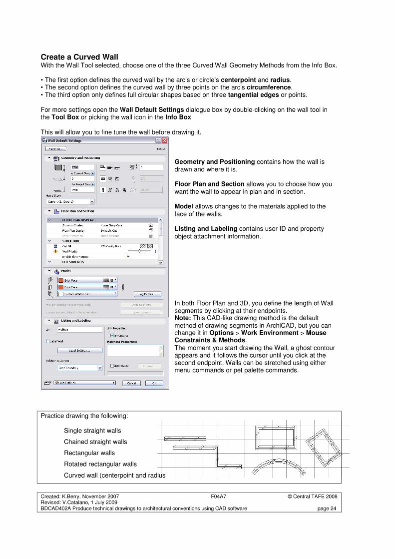
Create a Curved Wall With the Wall Tool selected, choose one of the three Curved Wall Geometry Methods from the Info Box. • The first option defines the curved wall by the arc’s or circle’s centerpoint and radius. • The second option defines the curved wall by three points on the arc’s circumference. • The third option only defines full circular shapes based on three tangential edges or points. For more settings open the Wall Default Settings dialogue box by double-clicking on the wall tool in the Tool Box or picking the wall icon in the Info Box This will allow you to fine tune the wall before drawing it.
Geometry and Positioning contains how the wall is drawn and where it is. Floor Plan and Section allows you to choose how you want the wall to appear in plan and in section. Model allows changes to the materials applied to the face of the walls. Listing and Labeling contains user ID and property object attachment information. In both Floor Plan and 3D, you define the length of Wall segments by clicking at their endpoints. Note: This CAD-like drawing method is the default method of drawing segments in ArchiCAD, but you can change it in Options > Work Environment > Mouse Constraints & Methods.
The moment you start drawing the Wall, a ghost contour appears and it follows the cursor until you click at the second endpoint. Walls can be stretched using either menu commands or pet palette commands.
Practice drawing the following: Single straight walls
Chained straight walls
Rectangular walls
Rotated rectangular walls
Curved wall (centerpoint and radius
Created: K.Berry, November 2007 F04A7 © Central TAFE 2008 Revised: V.Catalano, 1 July 2009 BDCAD402A Produce technical drawings to architectural conventions using CAD software page 25
Parametric Objects
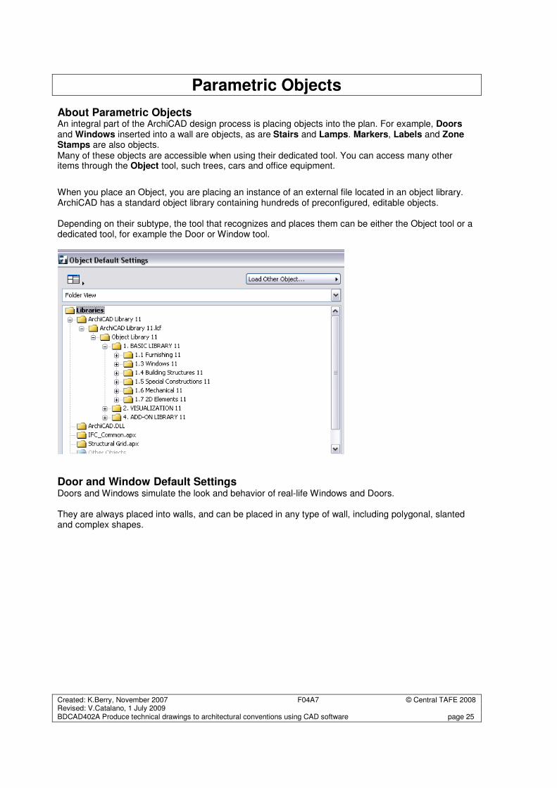
About Parametric Objects An integral part of the ArchiCAD design process is placing objects into the plan. For example, Doors and Windows inserted into a wall are objects, as are Stairs and Lamps. Markers, Labels and Zone Stamps are also objects. Many of these objects are accessible when using their dedicated tool. You can access many other items through the Object tool, such trees, cars and office equipment.
When you place an Object, you are placing an instance of an external file located in an object library. ArchiCAD has a standard object library containing hundreds of preconfigured, editable objects. Depending on their subtype, the tool that recognizes and places them can be either the Object tool or a dedicated tool, for example the Door or Window tool.
Door and Window Default Settings Doors and Windows simulate the look and behavior of real-life Windows and Doors. They are always placed into walls, and can be placed in any type of wall, including polygonal, slanted and complex shapes.
Created: K.Berry, November 2007 F04A7 © Central TAFE 2008 Revised: V.Catalano, 1 July 2009 BDCAD402A Produce technical drawings to architectural conventions using CAD software page 26
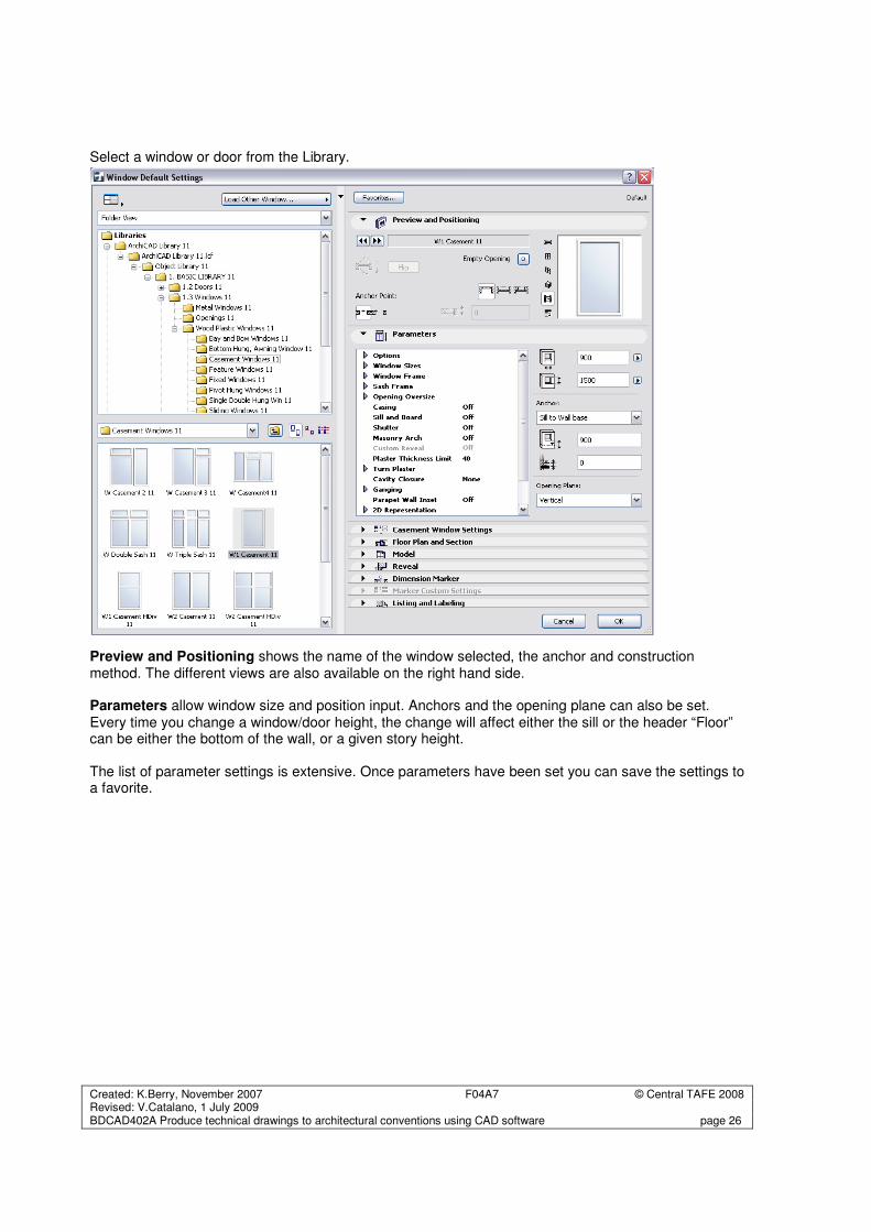
Select a window or door from the Library.
Preview and Positioning shows the name of the window selected, the anchor and construction method. The different views are also available on the right hand side. Parameters allow window size and position input. Anchors and the opening plane can also be set. Every time you change a window/door height, the change will affect either the sill or the header “Floor” can be either the bottom of the wall, or a given story height. The list of parameter settings is extensive. Once parameters have been set you can save the settings to a favorite.
Created: K.Berry, November 2007 F04A7 © Central TAFE 2008 Revised: V.Catalano, 1 July 2009 BDCAD402A Produce technical drawings to architectural conventions using CAD software page 27
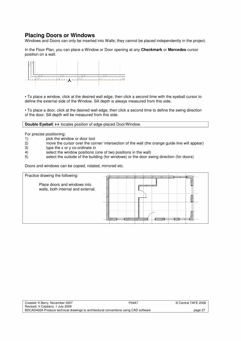
Placing Doors or Windows
Windows and Doors can only be inserted into Walls; they cannot be placed independently in the project. In the Floor Plan, you can place a Window or Door opening at any Checkmark or Mercedes cursor position on a wall.
• To place a window, click at the desired wall edge, then click a second time with the eyeball cursor to define the external side of the Window. Sill depth is always measured from this side. • To place a door, click at the desired wall edge, then click a second time to define the swing direction of the door. Sill depth will be measured from this side.
Double Eyeball locates position of edge-placed Door/Window.
For precise positioning: 1) pick the window or door tool 2) move the cursor over the corner/ intersection of the wall (the orange guide line will appear) 3) type the x or y co-ordinate in 4) select the window positions (one of two positions in the wall) 5) select the outside of the building (for windows) or the door swing direction (for doors) Doors and windows can be copied, rotated, mirrored etc.
Practice drawing the following: Place doors and windows into walls, both internal and external.
Created: K.Berry, November 2007 F04A7 © Central TAFE 2008 Revised: V.Catalano, 1 July 2009 BDCAD402A Produce technical drawings to architectural conventions using CAD software page 28
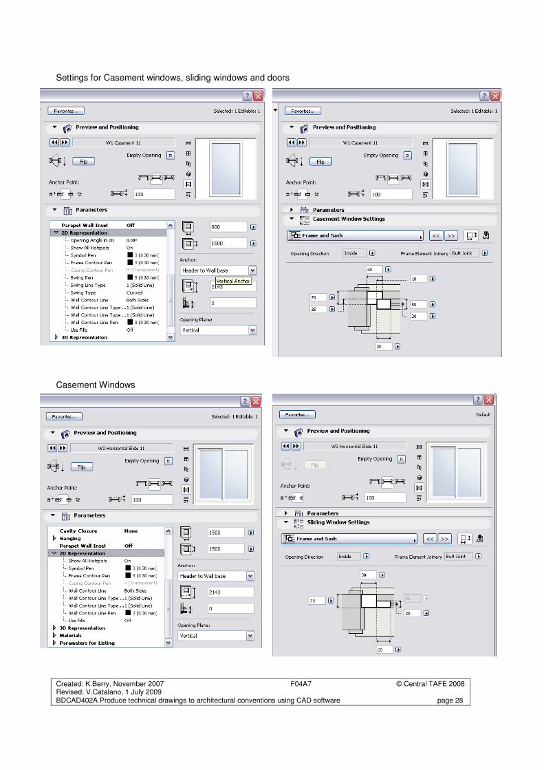
Settings for Casement windows, sliding windows and doors
Casement Windows
Created: K.Berry, November 2007 F04A7 © Central TAFE 2008 Revised: V.Catalano, 1 July 2009 BDCAD402A Produce technical drawings to architectural conventions using CAD software page 29
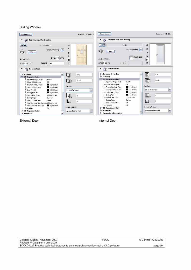
Sliding Window
External Door Internal Door
Created: K.Berry, November 2007 F04A7 © Central TAFE 2008 Revised: V.Catalano, 1 July 2009 BDCAD402A Produce technical drawings to architectural conventions using CAD software page 30
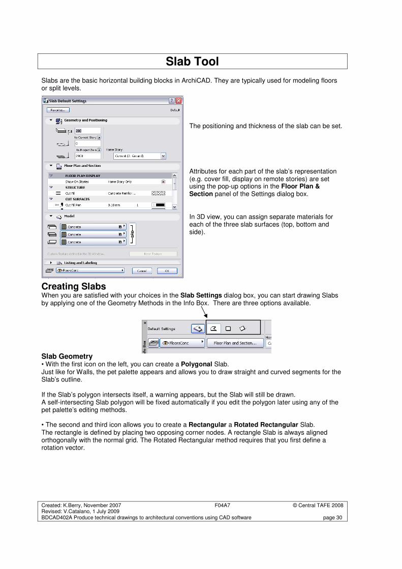
Slab Tool Slabs are the basic horizontal building blocks in ArchiCAD. They are typically used for modeling floors or split levels.
The positioning and thickness of the slab can be set. Attributes for each part of the slab’s representation (e.g. cover fill, display on remote stories) are set using the pop-up options in the Floor Plan & Section panel of the Settings dialog box. In 3D view, you can assign separate materials for each of the three slab surfaces (top, bottom and side).
Creating Slabs When you are satisfied with your choices in the Slab Settings dialog box, you can start drawing Slabs by applying one of the Geometry Methods in the Info Box. There are three options available.
Slab Geometry • With the first icon on the left, you can create a Polygonal Slab. Just like for Walls, the pet palette appears and allows you to draw straight and curved segments for the Slab’s outline. If the Slab’s polygon intersects itself, a warning appears, but the Slab will still be drawn. A self-intersecting Slab polygon will be fixed automatically if you edit the polygon later using any of the pet palette’s editing methods. • The second and third icon allows you to create a Rectangular a Rotated Rectangular Slab. The rectangle is defined by placing two opposing corner nodes. A rectangle Slab is always aligned orthogonally with the normal grid. The Rotated Rectangular method requires that you first define a rotation vector.
Created: K.Berry, November 2007 F04A7 © Central TAFE 2008 Revised: V.Catalano, 1 July 2009 BDCAD402A Produce technical drawings to architectural conventions using CAD software page 31
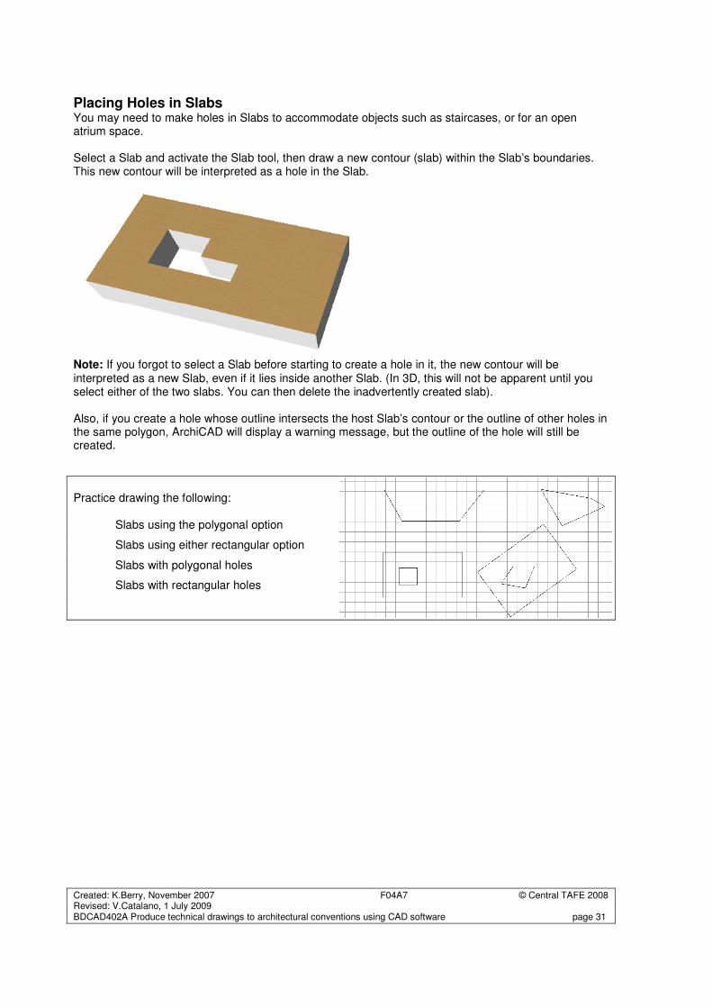
Placing Holes in Slabs You may need to make holes in Slabs to accommodate objects such as staircases, or for an open atrium space. Select a Slab and activate the Slab tool, then draw a new contour (slab) within the Slab’s boundaries. This new contour will be interpreted as a hole in the Slab.
Note: If you forgot to select a Slab before starting to create a hole in it, the new contour will be interpreted as a new Slab, even if it lies inside another Slab. (In 3D, this will not be apparent until you select either of the two slabs. You can then delete the inadvertently created slab). Also, if you create a hole whose outline intersects the host Slab’s contour or the outline of other holes in the same polygon, ArchiCAD will display a warning message, but the outline of the hole will still be created.
Practice drawing the following: Slabs using the polygonal option
Slabs using either rectangular option
Slabs with polygonal holes
Slabs with rectangular holes
Created: K.Berry, November 2007 F04A7 © Central TAFE 2008 Revised: V.Catalano, 1 July 2009 BDCAD402A Produce technical drawings to architectural conventions using CAD software page 32
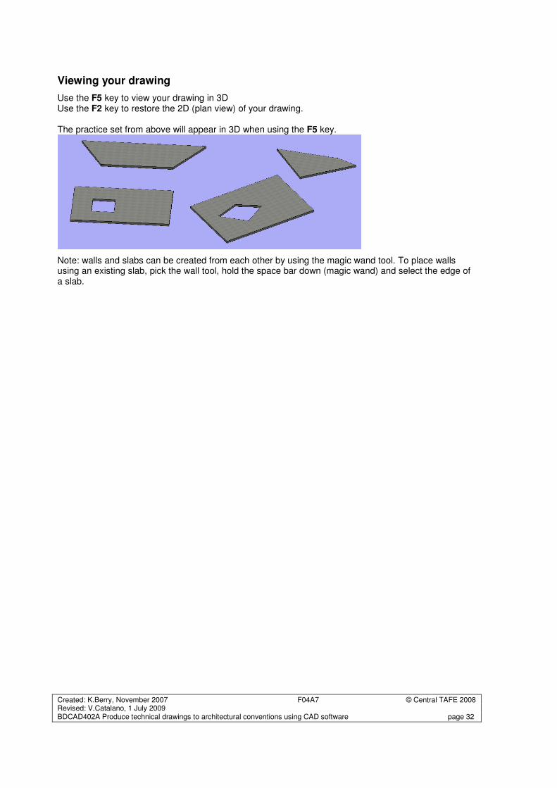
Viewing your drawing
Use the F5 key to view your drawing in 3D Use the F2 key to restore the 2D (plan view) of your drawing. The practice set from above will appear in 3D when using the F5 key.
Note: walls and slabs can be created from each other by using the magic wand tool. To place walls using an existing slab, pick the wall tool, hold the space bar down (magic wand) and select the edge of a slab.
Created: K.Berry, November 2007 F04A7 © Central TAFE 2008 Revised: V.Catalano, 1 July 2009 BDCAD402A Produce technical drawings to architectural conventions using CAD software page 33
Roof Tool
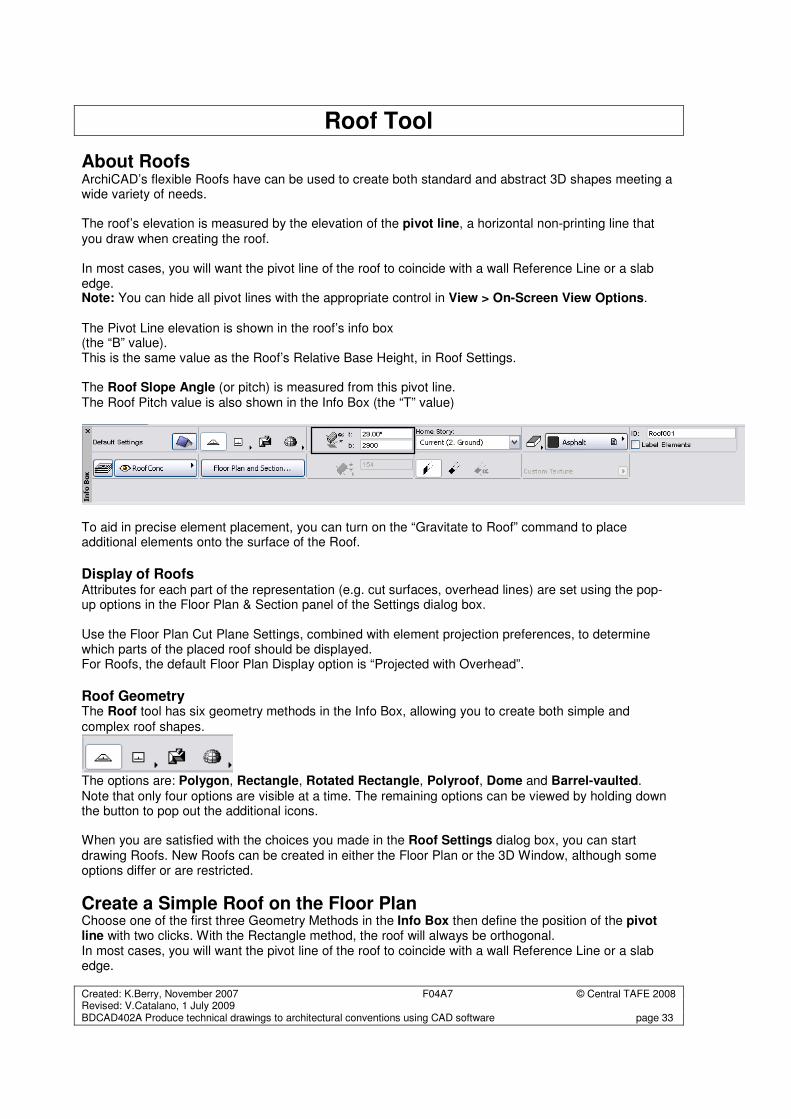
About Roofs ArchiCAD’s flexible Roofs have can be used to create both standard and abstract 3D shapes meeting a wide variety of needs. The roof’s elevation is measured by the elevation of the pivot line, a horizontal non-printing line that you draw when creating the roof. In most cases, you will want the pivot line of the roof to coincide with a wall Reference Line or a slab edge. Note: You can hide all pivot lines with the appropriate control in View > On-Screen View Options.
The Pivot Line elevation is shown in the roof’s info box (the “B” value). This is the same value as the Roof’s Relative Base Height, in Roof Settings. The Roof Slope Angle (or pitch) is measured from this pivot line. The Roof Pitch value is also shown in the Info Box (the “T” value)
To aid in precise element placement, you can turn on the “Gravitate to Roof” command to place additional elements onto the surface of the Roof.
Display of Roofs Attributes for each part of the representation (e.g. cut surfaces, overhead lines) are set using the pop-up options in the Floor Plan & Section panel of the Settings dialog box. Use the Floor Plan Cut Plane Settings, combined with element projection preferences, to determine which parts of the placed roof should be displayed. For Roofs, the default Floor Plan Display option is “Projected with Overhead”.
Roof Geometry The Roof tool has six geometry methods in the Info Box, allowing you to create both simple and
complex roof shapes.
The options are: Polygon, Rectangle, Rotated Rectangle, Polyroof, Dome and Barrel-vaulted.
Note that only four options are visible at a time. The remaining options can be viewed by holding down the button to pop out the additional icons. When you are satisfied with the choices you made in the Roof Settings dialog box, you can start drawing Roofs. New Roofs can be created in either the Floor Plan or the 3D Window, although some options differ or are restricted.
Create a Simple Roof on the Floor Plan Choose one of the first three Geometry Methods in the Info Box then define the position of the pivot line with two clicks. With the Rectangle method, the roof will always be orthogonal. In most cases, you will want the pivot line of the roof to coincide with a wall Reference Line or a slab edge.
Created: K.Berry, November 2007 F04A7 © Central TAFE 2008 Revised: V.Catalano, 1 July 2009 BDCAD402A Produce technical drawings to architectural conventions using CAD software page 34
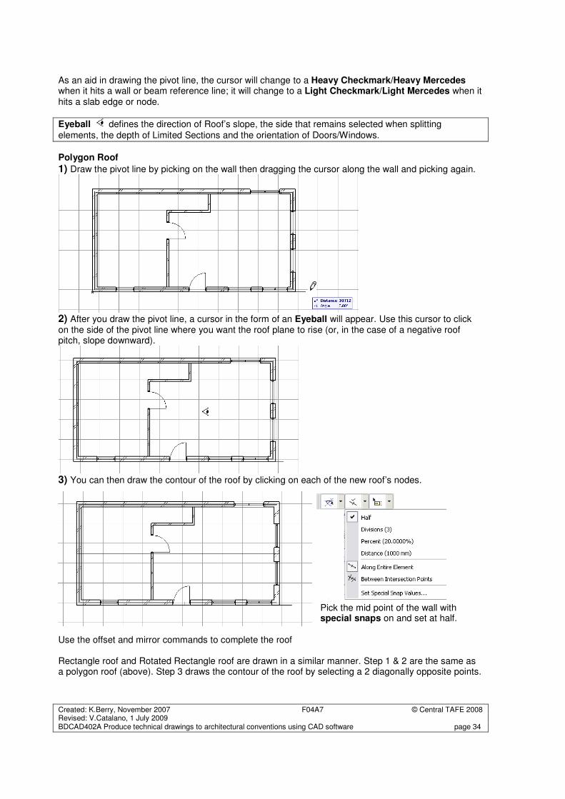
As an aid in drawing the pivot line, the cursor will change to a Heavy Checkmark/Heavy Mercedes when it hits a wall or beam reference line; it will change to a Light Checkmark/Light Mercedes when it hits a slab edge or node.
Eyeball defines the direction of Roof’s slope, the side that remains selected when splitting
elements, the depth of Limited Sections and the orientation of Doors/Windows.
Polygon Roof
1) Draw the pivot line by picking on the wall then dragging the cursor along the wall and picking again.
2) After you draw the pivot line, a cursor in the form of an Eyeball will appear. Use this cursor to click on the side of the pivot line where you want the roof plane to rise (or, in the case of a negative roof pitch, slope downward).
3) You can then draw the contour of the roof by clicking on each of the new roof’s nodes.
Pick the mid point of the wall with special snaps on and set at half.
Use the offset and mirror commands to complete the roof Rectangle roof and Rotated Rectangle roof are drawn in a similar manner. Step 1 & 2 are the same as a polygon roof (above). Step 3 draws the contour of the roof by selecting a 2 diagonally opposite points.
Created: K.Berry, November 2007 F04A7 © Central TAFE 2008 Revised: V.Catalano, 1 July 2009 BDCAD402A Produce technical drawings to architectural conventions using CAD software page 35
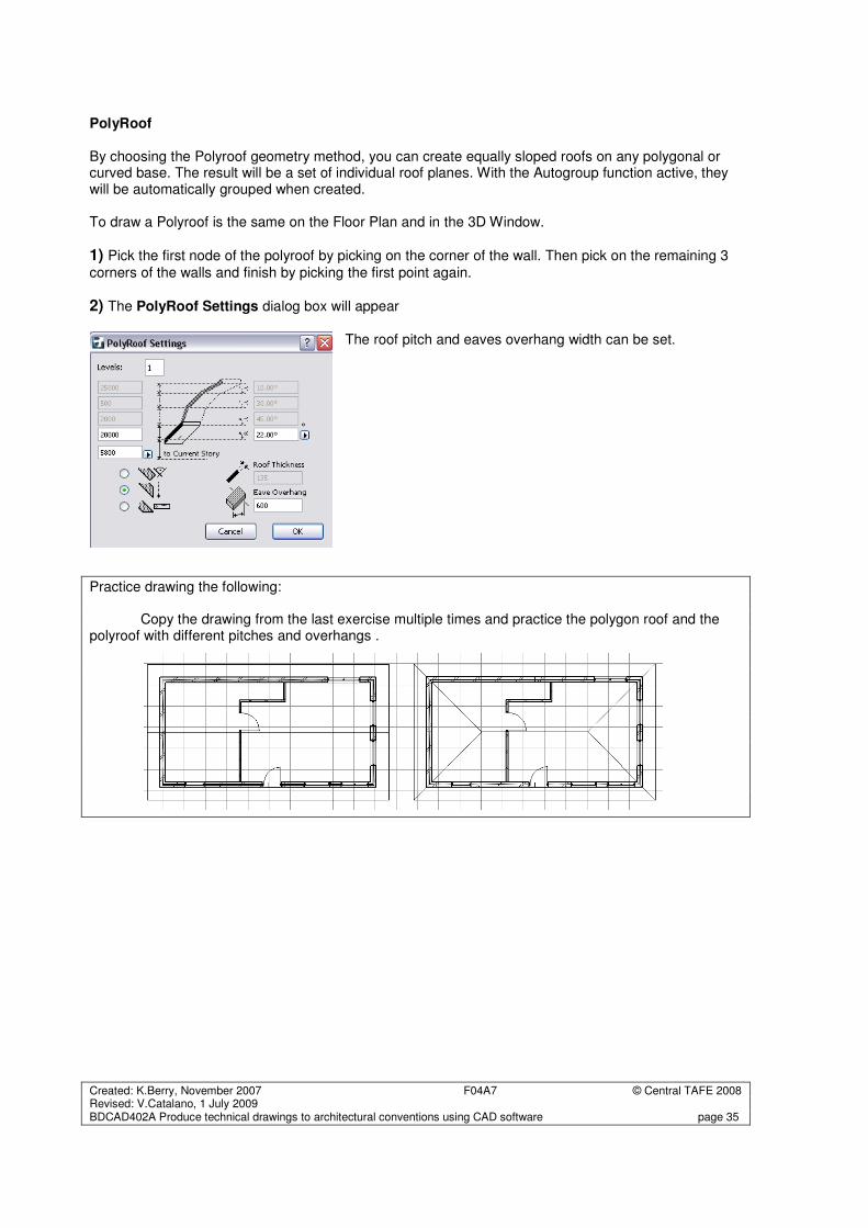
PolyRoof By choosing the Polyroof geometry method, you can create equally sloped roofs on any polygonal or curved base. The result will be a set of individual roof planes. With the Autogroup function active, they will be automatically grouped when created. To draw a Polyroof is the same on the Floor Plan and in the 3D Window.
1) Pick the first node of the polyroof by picking on the corner of the wall. Then pick on the remaining 3
corners of the walls and finish by picking the first point again.
2) The PolyRoof Settings dialog box will appear
The roof pitch and eaves overhang width can be set.
Practice drawing the following: Copy the drawing from the last exercise multiple times and practice the polygon roof and the polyroof with different pitches and overhangs .
Created: K.Berry, November 2007 F04A7 © Central TAFE 2008 Revised: V.Catalano, 1 July 2009 BDCAD402A Produce technical drawings to architectural conventions using CAD software page 36
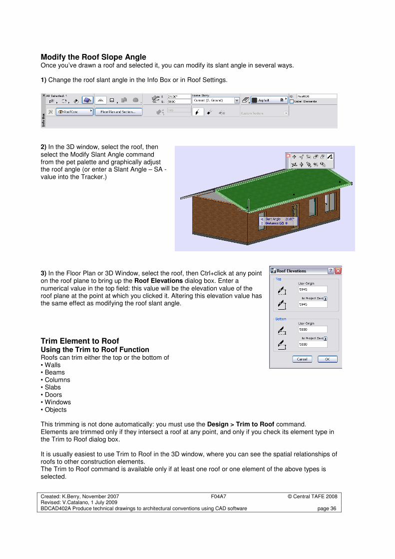
Modify the Roof Slope Angle Once you’ve drawn a roof and selected it, you can modify its slant angle in several ways. 1) Change the roof slant angle in the Info Box or in Roof Settings.
2) In the 3D window, select the roof, then select the Modify Slant Angle command from the pet palette and graphically adjust the roof angle (or enter a Slant Angle – SA - value into the Tracker.) 3) In the Floor Plan or 3D Window, select the roof, then Ctrl+click at any point on the roof plane to bring up the Roof Elevations dialog box. Enter a numerical value in the top field: this value will be the elevation value of the roof plane at the point at which you clicked it. Altering this elevation value has the same effect as modifying the roof slant angle.
Trim Element to Roof Using the Trim to Roof Function Roofs can trim either the top or the bottom of • Walls • Beams • Columns • Slabs • Doors • Windows • Objects This trimming is not done automatically: you must use the Design > Trim to Roof command. Elements are trimmed only if they intersect a roof at any point, and only if you check its element type in the Trim to Roof dialog box. It is usually easiest to use Trim to Roof in the 3D window, where you can see the spatial relationships of roofs to other construction elements. The Trim to Roof command is available only if at least one roof or one element of the above types is selected.
Created: K.Berry, November 2007 F04A7 © Central TAFE 2008 Revised: V.Catalano, 1 July 2009 BDCAD402A Produce technical drawings to architectural conventions using CAD software page 37
To trim elements to a roof, follow these steps:
1) Do one of the following: • Select the elements you wish to trim. (Remember, only elements which intersect a roof at any point can be trimmed); or • Select the roof(s) to which you want to trim elements; or • Select both elements and roof(s). Selection of roofs and/or elements narrows the scope of the Trim. If you select only a roof, all eligible elements are trimmed; if you select only elements, they will be trimmed to all the eligible roofs.
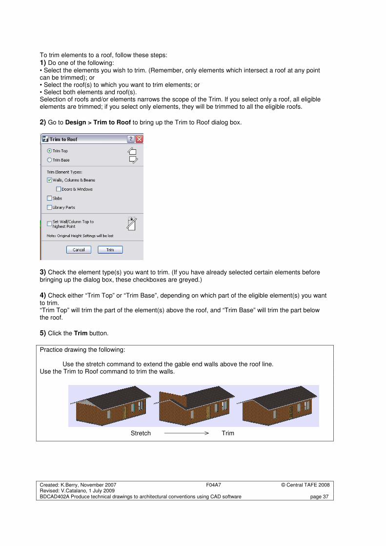
2) Go to Design > Trim to Roof to bring up the Trim to Roof dialog box.
3) Check the element type(s) you want to trim. (If you have already selected certain elements before bringing up the dialog box, these checkboxes are greyed.)
4) Check either “Trim Top” or “Trim Base”, depending on which part of the eligible element(s) you want to trim. “Trim Top” will trim the part of the element(s) above the roof, and “Trim Base” will trim the part below the roof.
5) Click the Trim button.
Practice drawing the following: Use the stretch command to extend the gable end walls above the roof line. Use the Trim to Roof command to trim the walls.
Stretch Trim
Created: K.Berry, November 2007 F04A7 © Central TAFE 2008 Revised: V.Catalano, 1 July 2009 BDCAD402A Produce technical drawings to architectural conventions using CAD software page 38
Text
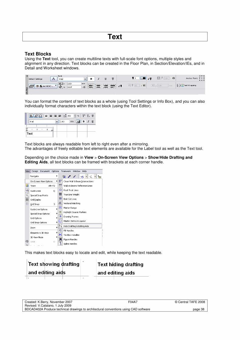
Text Blocks Using the Text tool, you can create multiline texts with full-scale font options, multiple styles and alignment in any direction. Text blocks can be created in the Floor Plan, in Section/Elevation/IEs, and in Detail and Worksheet windows.
You can format the content of text blocks as a whole (using Tool Settings or Info Box), and you can also individually format characters within the text block (using the Text Editor).
Text blocks are always readable from left to right even after a mirroring. The advantages of freely editable text elements are available for the Label tool as well as the Text tool. Depending on the choice made in View > On-Screen View Options > Show/Hide Drafting and Editing Aids, all text blocks can be framed with brackets at each corner handle. This makes text blocks easy to locate and edit, while keeping the text readable.
Created: K.Berry, November 2007 F04A7 © Central TAFE 2008 Revised: V.Catalano, 1 July 2009 BDCAD402A Produce technical drawings to architectural conventions using CAD software page 39
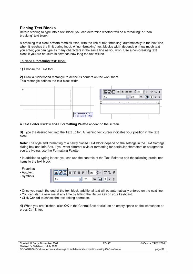
Placing Text Blocks Before starting to type into a text block, you can determine whether will be a “breaking” or “non-breaking” text block. A breaking text block’s width remains fixed, with the line of text “breaking” automatically to the next line when it reaches the limit during input. A “non-breaking” text block’s width depends on how much text you enter; you can type as many characters in the same line as you wish. Use a non-breaking text block if you are not sure in advance how long the text will be. To place a “breaking text” block:
1) Choose the Text tool.
2) Draw a rubberband rectangle to define its corners on the worksheet.
This rectangle defines the text block width.
A Text Editor window and a Formatting Palette appear on the screen.
3) Type the desired text into the Text Editor. A flashing text cursor indicates your position in the text block. Note: The style and formatting of a newly placed Text Block depend on the settings in the Text Settings dialog box and Info Box. If you want different style or formatting for particular characters or paragraphs you are typing, use the Formatting Palette. • In addition to typing in text, you can use the controls of the Text Editor to add the following predefined items to the text block - Favorites - Autotext - Symbols • Once you reach the end of the text block, additional text will be automatically entered on the next line. • You can start a new line at any time by hitting the Return key on your keyboard. • Click Cancel to cancel the text editing operation.
4) When you are finished, click OK in the Control Box; or click on an empty space on the worksheet; or press Ctrl-Enter.
Created: K.Berry, November 2007 F04A7 © Central TAFE 2008 Revised: V.Catalano, 1 July 2009 BDCAD402A Produce technical drawings to architectural conventions using CAD software page 40
To place a “non-breaking” text block:
1) Choose the Text tool.
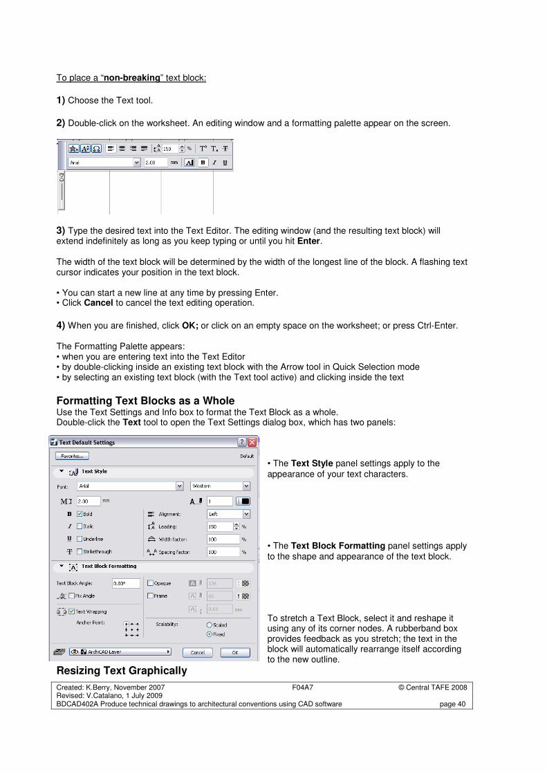
2) Double-click on the worksheet. An editing window and a formatting palette appear on the screen.
3) Type the desired text into the Text Editor. The editing window (and the resulting text block) will extend indefinitely as long as you keep typing or until you hit Enter. The width of the text block will be determined by the width of the longest line of the block. A flashing text cursor indicates your position in the text block. • You can start a new line at any time by pressing Enter. • Click Cancel to cancel the text editing operation.
4) When you are finished, click OK; or click on an empty space on the worksheet; or press Ctrl-Enter. The Formatting Palette appears: • when you are entering text into the Text Editor • by double-clicking inside an existing text block with the Arrow tool in Quick Selection mode • by selecting an existing text block (with the Text tool active) and clicking inside the text
Formatting Text Blocks as a Whole Use the Text Settings and Info box to format the Text Block as a whole. Double-click the Text tool to open the Text Settings dialog box, which has two panels:
• The Text Style panel settings apply to the
appearance of your text characters. • The Text Block Formatting panel settings apply to the shape and appearance of the text block. To stretch a Text Block, select it and reshape it using any of its corner nodes. A rubberband box provides feedback as you stretch; the text in the block will automatically rearrange itself according to the new outline.
Resizing Text Graphically
Created: K.Berry, November 2007 F04A7 © Central TAFE 2008 Revised: V.Catalano, 1 July 2009 BDCAD402A Produce technical drawings to architectural conventions using CAD software page 41
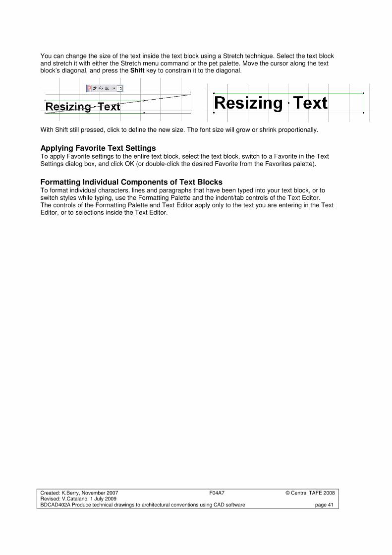
You can change the size of the text inside the text block using a Stretch technique. Select the text block and stretch it with either the Stretch menu command or the pet palette. Move the cursor along the text block’s diagonal, and press the Shift key to constrain it to the diagonal.
With Shift still pressed, click to define the new size. The font size will grow or shrink proportionally.
Applying Favorite Text Settings To apply Favorite settings to the entire text block, select the text block, switch to a Favorite in the Text Settings dialog box, and click OK (or double-click the desired Favorite from the Favorites palette).
Formatting Individual Components of Text Blocks To format individual characters, lines and paragraphs that have been typed into your text block, or to switch styles while typing, use the Formatting Palette and the indent/tab controls of the Text Editor. The controls of the Formatting Palette and Text Editor apply only to the text you are entering in the Text Editor, or to selections inside the Text Editor.
Created: K.Berry, November 2007 F04A7 © Central TAFE 2008 Revised: V.Catalano, 1 July 2009 BDCAD402A Produce technical drawings to architectural conventions using CAD software page 42
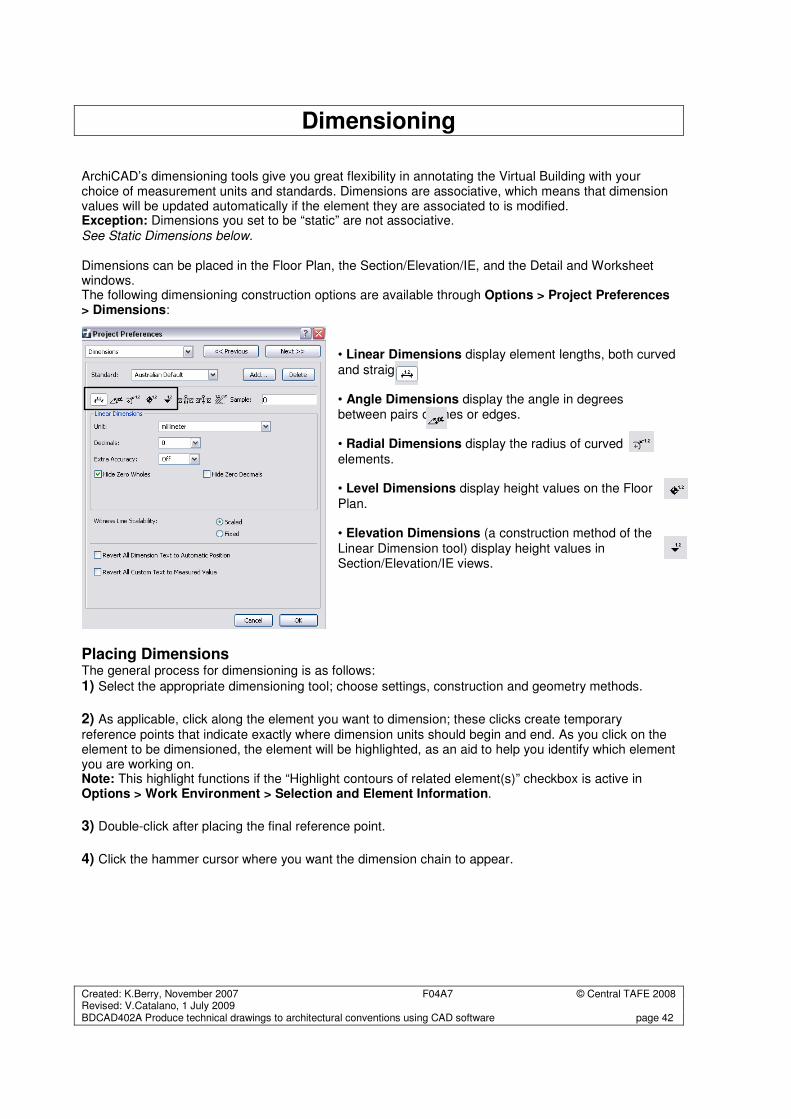
Dimensioning ArchiCAD’s dimensioning tools give you great flexibility in annotating the Virtual Building with your choice of measurement units and standards. Dimensions are associative, which means that dimension values will be updated automatically if the element they are associated to is modified. Exception: Dimensions you set to be “static” are not associative. See Static Dimensions below. Dimensions can be placed in the Floor Plan, the Section/Elevation/IE, and the Detail and Worksheet windows. The following dimensioning construction options are available through Options > Project Preferences > Dimensions:
• Linear Dimensions display element lengths, both curved
and straight. • Angle Dimensions display the angle in degrees between pairs of lines or edges. • Radial Dimensions display the radius of curved
elements. • Level Dimensions display height values on the Floor
Plan. • Elevation Dimensions (a construction method of the Linear Dimension tool) display height values in Section/Elevation/IE views.
Placing Dimensions The general process for dimensioning is as follows:
1) Select the appropriate dimensioning tool; choose settings, construction and geometry methods.
2) As applicable, click along the element you want to dimension; these clicks create temporary reference points that indicate exactly where dimension units should begin and end. As you click on the element to be dimensioned, the element will be highlighted, as an aid to help you identify which element you are working on. Note: This highlight functions if the “Highlight contours of related element(s)” checkbox is active in Options > Work Environment > Selection and Element Information.
3) Double-click after placing the final reference point.
4) Click the hammer cursor where you want the dimension chain to appear.
Created: K.Berry, November 2007 F04A7 © Central TAFE 2008 Revised: V.Catalano, 1 July 2009 BDCAD402A Produce technical drawings to architectural conventions using CAD software page 43
Dimensioning Standards ArchiCAD supports the use of different Dimensioning Standards. You can customize their use for the current project in Options > Project Preferences > Dimensions. This is particularly useful when working on several Projects with differing levels of accuracy (construction details versus site plans)
• Hammer places Dimension chains, Angular Dimensions, the Elevation Dimension array, Zone
Stamps and Fill areas; it also appears when closing polygons.
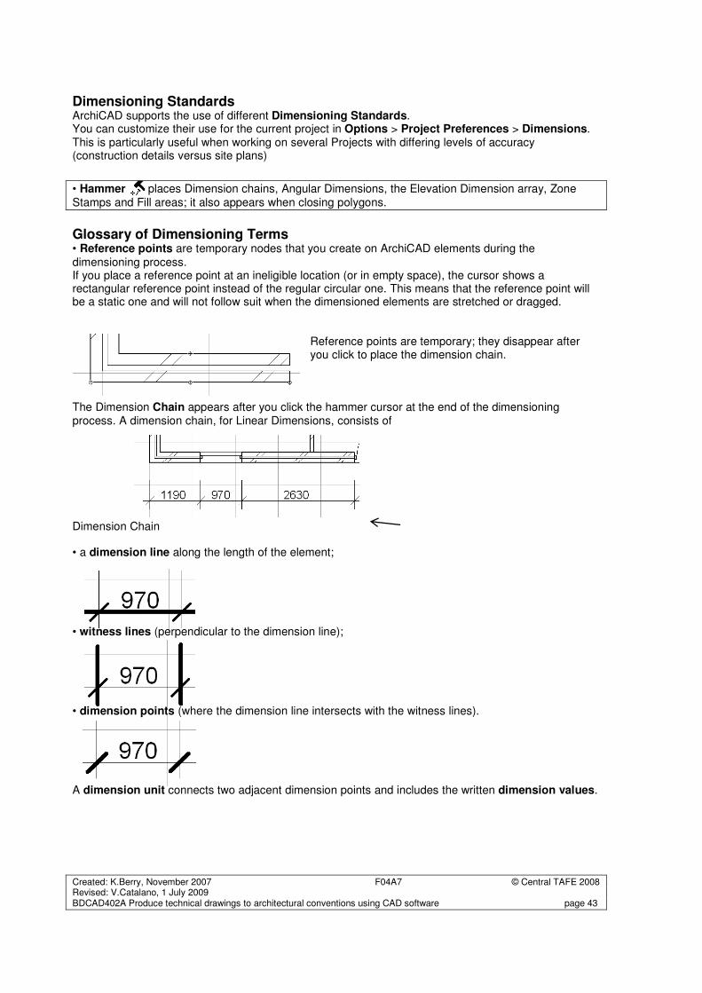
Glossary of Dimensioning Terms • Reference points are temporary nodes that you create on ArchiCAD elements during the
dimensioning process. If you place a reference point at an ineligible location (or in empty space), the cursor shows a rectangular reference point instead of the regular circular one. This means that the reference point will be a static one and will not follow suit when the dimensioned elements are stretched or dragged.
Reference points are temporary; they disappear after you click to place the dimension chain.
The Dimension Chain appears after you click the hammer cursor at the end of the dimensioning process. A dimension chain, for Linear Dimensions, consists of Dimension Chain • a dimension line along the length of the element;
• witness lines (perpendicular to the dimension line);
• dimension points (where the dimension line intersects with the witness lines). A dimension unit connects two adjacent dimension points and includes the written dimension values.
Created: K.Berry, November 2007 F04A7 © Central TAFE 2008 Revised: V.Catalano, 1 July 2009 BDCAD402A Produce technical drawings to architectural conventions using CAD software page 44
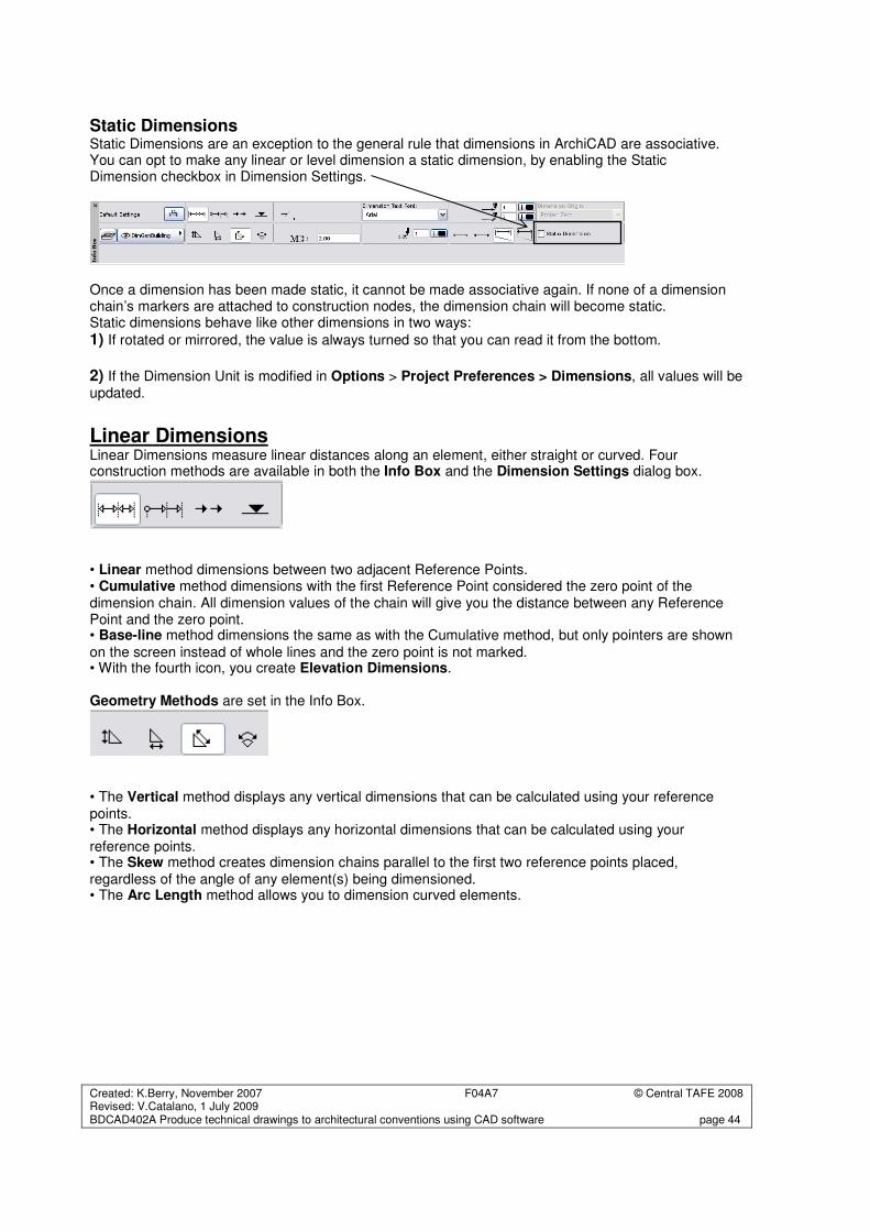
Static Dimensions Static Dimensions are an exception to the general rule that dimensions in ArchiCAD are associative. You can opt to make any linear or level dimension a static dimension, by enabling the Static Dimension checkbox in Dimension Settings.
Once a dimension has been made static, it cannot be made associative again. If none of a dimension chain’s markers are attached to construction nodes, the dimension chain will become static. Static dimensions behave like other dimensions in two ways:
1) If rotated or mirrored, the value is always turned so that you can read it from the bottom.
2) If the Dimension Unit is modified in Options > Project Preferences > Dimensions, all values will be updated.
Linear Dimensions Linear Dimensions measure linear distances along an element, either straight or curved. Four construction methods are available in both the Info Box and the Dimension Settings dialog box.
• Linear method dimensions between two adjacent Reference Points. • Cumulative method dimensions with the first Reference Point considered the zero point of the dimension chain. All dimension values of the chain will give you the distance between any Reference Point and the zero point. • Base-line method dimensions the same as with the Cumulative method, but only pointers are shown
on the screen instead of whole lines and the zero point is not marked. • With the fourth icon, you create Elevation Dimensions. Geometry Methods are set in the Info Box.
• The Vertical method displays any vertical dimensions that can be calculated using your reference points. • The Horizontal method displays any horizontal dimensions that can be calculated using your reference points. • The Skew method creates dimension chains parallel to the first two reference points placed, regardless of the angle of any element(s) being dimensioned. • The Arc Length method allows you to dimension curved elements.
Created: K.Berry, November 2007 F04A7 © Central TAFE 2008 Revised: V.Catalano, 1 July 2009 BDCAD402A Produce technical drawings to architectural conventions using CAD software page 45
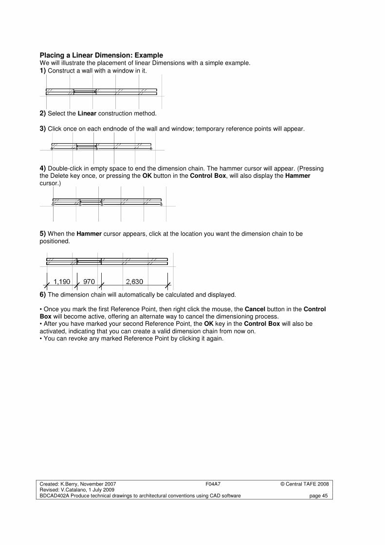
Placing a Linear Dimension: Example We will illustrate the placement of linear Dimensions with a simple example.
1) Construct a wall with a window in it.
2) Select the Linear construction method.
3) Click once on each endnode of the wall and window; temporary reference points will appear.
4) Double-click in empty space to end the dimension chain. The hammer cursor will appear. (Pressing the Delete key once, or pressing the OK button in the Control Box, will also display the Hammer cursor.)
5) When the Hammer cursor appears, click at the location you want the dimension chain to be positioned.
6) The dimension chain will automatically be calculated and displayed.
• Once you mark the first Reference Point, then right click the mouse, the Cancel button in the Control Box will become active, offering an alternate way to cancel the dimensioning process. • After you have marked your second Reference Point, the OK key in the Control Box will also be
activated, indicating that you can create a valid dimension chain from now on. • You can revoke any marked Reference Point by clicking it again.
Created: K.Berry, November 2007 F04A7 © Central TAFE 2008 Revised: V.Catalano, 1 July 2009 BDCAD402A Produce technical drawings to architectural conventions using CAD software page 46
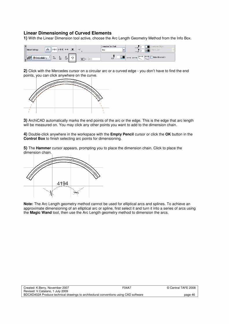
Linear Dimensioning of Curved Elements 1) With the Linear Dimension tool active, choose the Arc Length Geometry Method from the Info Box.
2) Click with the Mercedes cursor on a circular arc or a curved edge - you don’t have to find the end
points, you can click anywhere on the curve.
3) ArchiCAD automatically marks the end points of the arc or the edge. This is the edge that arc length will be measured on. You may click any other points you want to add to the dimension chain.
4) Double-click anywhere in the workspace with the Empty Pencil cursor or click the OK button in the Control Box to finish selecting arc points for dimensioning.
5) The Hammer cursor appears, prompting you to place the dimension chain. Click to place the dimension chain.
Note: The Arc Length geometry method cannot be used for elliptical arcs and splines. To achieve an
approximate dimensioning of an elliptical arc or spline, first select it and turn it into a series of arcs using the Magic Wand tool, then use the Arc Length geometry method to dimension the arcs.
Created: K.Berry, November 2007 F04A7 © Central TAFE 2008 Revised: V.Catalano, 1 July 2009 BDCAD402A Produce technical drawings to architectural conventions using CAD software page 47
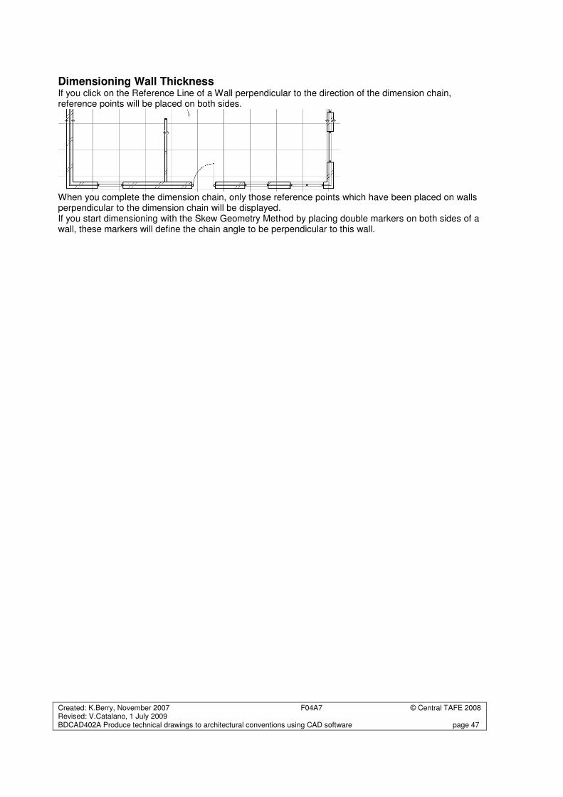
Dimensioning Wall Thickness If you click on the Reference Line of a Wall perpendicular to the direction of the dimension chain, reference points will be placed on both sides.
When you complete the dimension chain, only those reference points which have been placed on walls perpendicular to the dimension chain will be displayed. If you start dimensioning with the Skew Geometry Method by placing double markers on both sides of a wall, these markers will define the chain angle to be perpendicular to this wall.
Created: K.Berry, November 2007 F04A7 © Central TAFE 2008 Revised: V.Catalano, 1 July 2009 BDCAD402A Produce technical drawings to architectural conventions using CAD software page 48
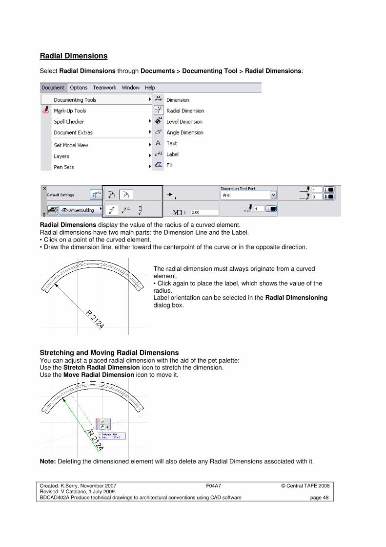
Radial Dimensions Select Radial Dimensions through Documents > Documenting Tool > Radial Dimensions:
Radial Dimensions display the value of the radius of a curved element.
Radial dimensions have two main parts: the Dimension Line and the Label. • Click on a point of the curved element. • Draw the dimension line, either toward the centerpoint of the curve or in the opposite direction.
The radial dimension must always originate from a curved element. • Click again to place the label, which shows the value of the radius. Label orientation can be selected in the Radial Dimensioning dialog box.
Stretching and Moving Radial Dimensions You can adjust a placed radial dimension with the aid of the pet palette: Use the Stretch Radial Dimension icon to stretch the dimension. Use the Move Radial Dimension icon to move it.
Note: Deleting the dimensioned element will also delete any Radial Dimensions associated with it.
Created: K.Berry, November 2007 F04A7 © Central TAFE 2008 Revised: V.Catalano, 1 July 2009 BDCAD402A Produce technical drawings to architectural conventions using CAD software page 49
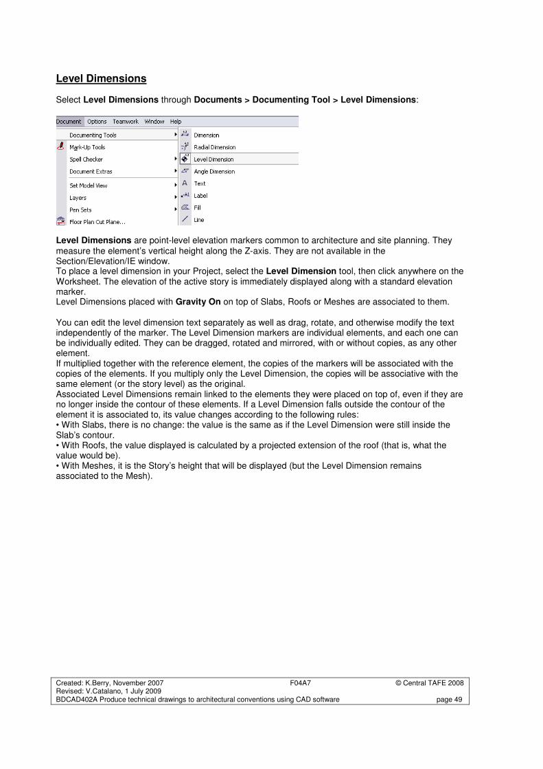
Level Dimensions Select Level Dimensions through Documents > Documenting Tool > Level Dimensions:
Level Dimensions are point-level elevation markers common to architecture and site planning. They
measure the element’s vertical height along the Z-axis. They are not available in the Section/Elevation/IE window. To place a level dimension in your Project, select the Level Dimension tool, then click anywhere on the Worksheet. The elevation of the active story is immediately displayed along with a standard elevation marker. Level Dimensions placed with Gravity On on top of Slabs, Roofs or Meshes are associated to them. You can edit the level dimension text separately as well as drag, rotate, and otherwise modify the text independently of the marker. The Level Dimension markers are individual elements, and each one can be individually edited. They can be dragged, rotated and mirrored, with or without copies, as any other element. If multiplied together with the reference element, the copies of the markers will be associated with the copies of the elements. If you multiply only the Level Dimension, the copies will be associative with the same element (or the story level) as the original. Associated Level Dimensions remain linked to the elements they were placed on top of, even if they are no longer inside the contour of these elements. If a Level Dimension falls outside the contour of the element it is associated to, its value changes according to the following rules: • With Slabs, there is no change: the value is the same as if the Level Dimension were still inside the Slab’s contour. • With Roofs, the value displayed is calculated by a projected extension of the roof (that is, what the value would be). • With Meshes, it is the Story’s height that will be displayed (but the Level Dimension remains associated to the Mesh).
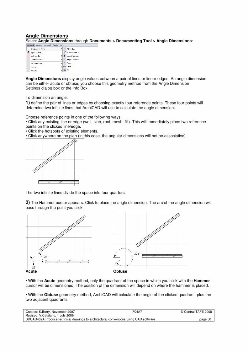
Created: K.Berry, November 2007 F04A7 © Central TAFE 2008 Revised: V.Catalano, 1 July 2009 BDCAD402A Produce technical drawings to architectural conventions using CAD software page 50
Angle Dimensions Select Angle Dimensions through Documents > Documenting Tool > Angle Dimensions:
Angle Dimensions display angle values between a pair of lines or linear edges. An angle dimension
can be either acute or obtuse; you choose this geometry method from the Angle Dimension Settings dialog box or the Info Box. To dimension an angle:
1) define the pair of lines or edges by choosing exactly four reference points. These four points will
determine two infinite lines that ArchiCAD will use to calculate the angle dimension. Choose reference points in one of the following ways: • Click any existing line or edge (wall, slab, roof, mesh, fill). This will immediately place two reference points on the clicked line/edge. • Click the hotspots of existing elements. • Click anywhere on the plan (in this case, the angular dimensions will not be associative).
The two infinite lines divide the space into four quarters.
2) The Hammer cursor appears. Click to place the angle dimension. The arc of the angle dimension will
pass through the point you click.
Acute Obtuse • With the Acute geometry method, only the quadrant of the space in which you click with the Hammer cursor will be dimensioned. The position of the dimension will depend on where the hammer is placed. • With the Obtuse geometry method, ArchiCAD will calculate the angle of the clicked quadrant, plus the two adjacent quadrants.
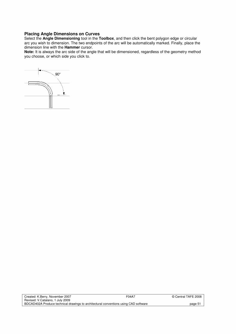
Created: K.Berry, November 2007 F04A7 © Central TAFE 2008 Revised: V.Catalano, 1 July 2009 BDCAD402A Produce technical drawings to architectural conventions using CAD software page 51
Placing Angle Dimensions on Curves Select the Angle Dimensioning tool in the Toolbox, and then click the bent polygon edge or circular
arc you wish to dimension. The two endpoints of the arc will be automatically marked. Finally, place the dimension line with the Hammer cursor. Note: It is always the arc side of the angle that will be dimensioned, regardless of the geometry method you choose, or which side you click to.
Created: K.Berry, November 2007 F04A7 © Central TAFE 2008 Revised: V.Catalano, 1 July 2009 BDCAD402A Produce technical drawings to architectural conventions using CAD software page 52
Elevation Dimensions Select Elevation Dimensions from the Tool Box: A special case of the linear Dimension tool is the Elevation Dimensioning construction method.
Elevation Dimensions allow you to place height markers in Section/Elevation/IE windows. Elevation Dimensioning is calculated based on the Dimension Origin, which you can set as needed in the Dimension Settings dialog box. A series of Elevation Dimensions behaves as an associative dimension chain. You can select and edit the whole series by clicking on the invisible axis of the chain (where the cursor changes to Mercedes with Arrow) with the Arrow tool or Shift-clicking with another tool active. Individual markers in the chain cannot be edited. For Elevation Dimensions only, you can choose the Reference Levels defined in Options > Project Preferences > Working Units & Levels for the placement of the dimensions.
You can also use Elevation Dimensions on the Floor Plan, but there they only measure the Floor Plan’s Y-axis from the current Project/User Origin. Place individual markers by clicking the point you want to dimension, then click OK in the Control Box. Use the Hammer cursor to position the marker. To place a chain of Elevation markers, click multiple points, then click OK and use the Hammer cursor to place the chain. Note: Hotlinked Modules placed in the Project may contain Elevation Dimensions that refer to a User Origin. In this case, the dimension values will be the same as in the source Project. Different rules apply if you move the Elevation Dimensions in the host Project: • If you select and move all elements related to an Elevation Dimension without selecting the dimension chain itself, the dimension chain will move with them. The origin of the dimension values will keep its position, which means that the numbers will change. • If you select and drag elements together with the Elevation Dimension they relate to, and the dimension chain has a custom origin, the origin will move with the dimensions, which means that the numbers will keep their values.
Associative Dimensions in Sections/Elevations/IE Dimensions in the Section/Elevation/IE Windows are associative, meaning that every dimension point you create adheres to its reference point. For instance, when you stretch the Window in the wall, it will cause the entire dimension chain to be automatically updated. Elevation Dimensions and Angle Dimensions are also associative. • When a Model type Section is turned into a Drawing type Section, hotspots are generated on the elements to mark the associated dimension points. • When the Drawing type Section is updated from the model, the dimensions associated to the hotspots will be regenerated to reflect the changes to the model.
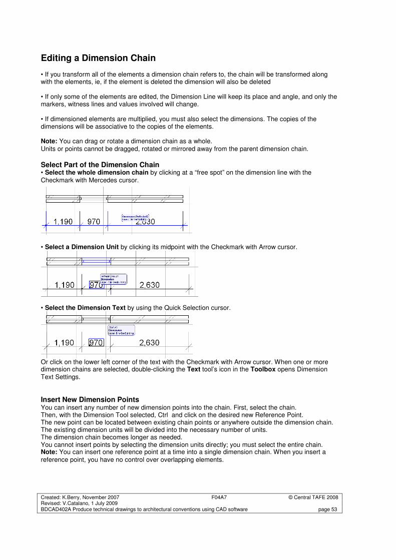
Created: K.Berry, November 2007 F04A7 © Central TAFE 2008 Revised: V.Catalano, 1 July 2009 BDCAD402A Produce technical drawings to architectural conventions using CAD software page 53
Editing a Dimension Chain • If you transform all of the elements a dimension chain refers to, the chain will be transformed along with the elements, ie, if the element is deleted the dimension will also be deleted • If only some of the elements are edited, the Dimension Line will keep its place and angle, and only the markers, witness lines and values involved will change. • If dimensioned elements are multiplied, you must also select the dimensions. The copies of the dimensions will be associative to the copies of the elements. Note: You can drag or rotate a dimension chain as a whole. Units or points cannot be dragged, rotated or mirrored away from the parent dimension chain.
Select Part of the Dimension Chain • Select the whole dimension chain by clicking at a “free spot” on the dimension line with the
Checkmark with Mercedes cursor.
• Select a Dimension Unit by clicking its midpoint with the Checkmark with Arrow cursor.
• Select the Dimension Text by using the Quick Selection cursor.
Or click on the lower left corner of the text with the Checkmark with Arrow cursor. When one or more dimension chains are selected, double-clicking the Text tool’s icon in the Toolbox opens Dimension Text Settings.
Insert New Dimension Points You can insert any number of new dimension points into the chain. First, select the chain. Then, with the Dimension Tool selected, Ctrl and click on the desired new Reference Point. The new point can be located between existing chain points or anywhere outside the dimension chain. The existing dimension units will be divided into the necessary number of units. The dimension chain becomes longer as needed. You cannot insert points by selecting the dimension units directly; you must select the entire chain. Note: You can insert one reference point at a time into a single dimension chain. When you insert a
reference point, you have no control over overlapping elements.
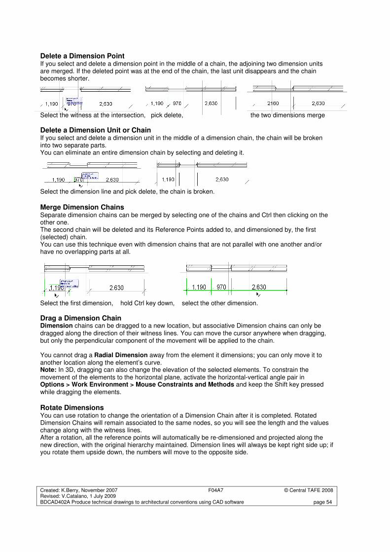
Created: K.Berry, November 2007 F04A7 © Central TAFE 2008 Revised: V.Catalano, 1 July 2009 BDCAD402A Produce technical drawings to architectural conventions using CAD software page 54
Delete a Dimension Point If you select and delete a dimension point in the middle of a chain, the adjoining two dimension units are merged. If the deleted point was at the end of the chain, the last unit disappears and the chain becomes shorter. Select the witness at the intersection, pick delete, the two dimensions merge
Delete a Dimension Unit or Chain If you select and delete a dimension unit in the middle of a dimension chain, the chain will be broken into two separate parts. You can eliminate an entire dimension chain by selecting and deleting it.
Select the dimension line and pick delete, the chain is broken.
Merge Dimension Chains Separate dimension chains can be merged by selecting one of the chains and Ctrl then clicking on the other one. The second chain will be deleted and its Reference Points added to, and dimensioned by, the first (selected) chain. You can use this technique even with dimension chains that are not parallel with one another and/or have no overlapping parts at all. Select the first dimension, hold Ctrl key down, select the other dimension.
Drag a Dimension Chain Dimension chains can be dragged to a new location, but associative Dimension chains can only be dragged along the direction of their witness lines. You can move the cursor anywhere when dragging, but only the perpendicular component of the movement will be applied to the chain. You cannot drag a Radial Dimension away from the element it dimensions; you can only move it to another location along the element’s curve. Note: In 3D, dragging can also change the elevation of the selected elements. To constrain the movement of the elements to the horizontal plane, activate the horizontal-vertical angle pair in Options > Work Environment > Mouse Constraints and Methods and keep the Shift key pressed while dragging the elements.
Rotate Dimensions You can use rotation to change the orientation of a Dimension Chain after it is completed. Rotated Dimension Chains will remain associated to the same nodes, so you will see the length and the values change along with the witness lines. After a rotation, all the reference points will automatically be re-dimensioned and projected along the new direction, with the original hierarchy maintained. Dimension lines will always be kept right side up; if you rotate them upside down, the numbers will move to the opposite side.
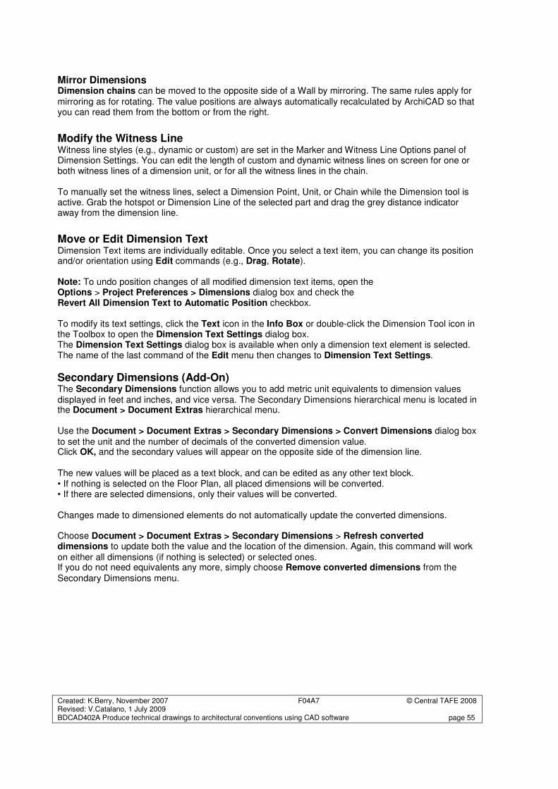
Created: K.Berry, November 2007 F04A7 © Central TAFE 2008 Revised: V.Catalano, 1 July 2009 BDCAD402A Produce technical drawings to architectural conventions using CAD software page 55
Mirror Dimensions Dimension chains can be moved to the opposite side of a Wall by mirroring. The same rules apply for
mirroring as for rotating. The value positions are always automatically recalculated by ArchiCAD so that you can read them from the bottom or from the right.
Modify the Witness Line Witness line styles (e.g., dynamic or custom) are set in the Marker and Witness Line Options panel of Dimension Settings. You can edit the length of custom and dynamic witness lines on screen for one or both witness lines of a dimension unit, or for all the witness lines in the chain. To manually set the witness lines, select a Dimension Point, Unit, or Chain while the Dimension tool is active. Grab the hotspot or Dimension Line of the selected part and drag the grey distance indicator away from the dimension line.
Move or Edit Dimension Text Dimension Text items are individually editable. Once you select a text item, you can change its position and/or orientation using Edit commands (e.g., Drag, Rotate). Note: To undo position changes of all modified dimension text items, open the Options > Project Preferences > Dimensions dialog box and check the Revert All Dimension Text to Automatic Position checkbox. To modify its text settings, click the Text icon in the Info Box or double-click the Dimension Tool icon in the Toolbox to open the Dimension Text Settings dialog box. The Dimension Text Settings dialog box is available when only a dimension text element is selected. The name of the last command of the Edit menu then changes to Dimension Text Settings.
Secondary Dimensions (Add-On) The Secondary Dimensions function allows you to add metric unit equivalents to dimension values displayed in feet and inches, and vice versa. The Secondary Dimensions hierarchical menu is located in the Document > Document Extras hierarchical menu. Use the Document > Document Extras > Secondary Dimensions > Convert Dimensions dialog box
to set the unit and the number of decimals of the converted dimension value. Click OK, and the secondary values will appear on the opposite side of the dimension line. The new values will be placed as a text block, and can be edited as any other text block. • If nothing is selected on the Floor Plan, all placed dimensions will be converted. • If there are selected dimensions, only their values will be converted. Changes made to dimensioned elements do not automatically update the converted dimensions. Choose Document > Document Extras > Secondary Dimensions > Refresh converted dimensions to update both the value and the location of the dimension. Again, this command will work
on either all dimensions (if nothing is selected) or selected ones. If you do not need equivalents any more, simply choose Remove converted dimensions from the
Secondary Dimensions menu.
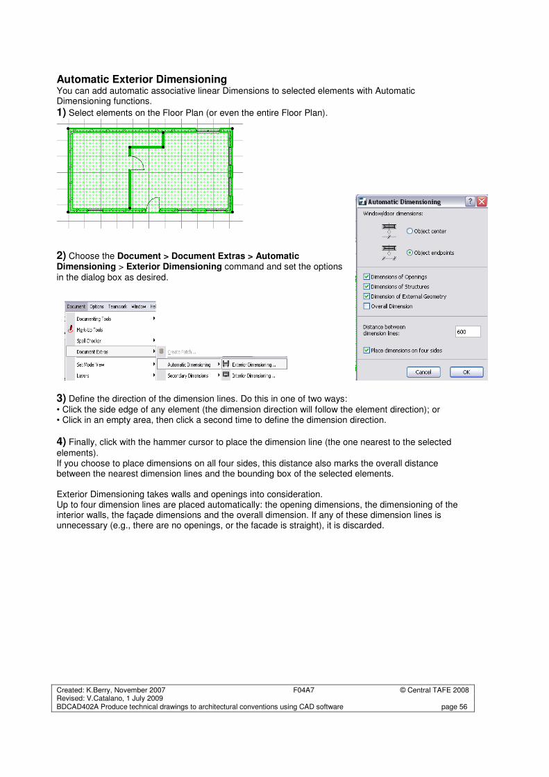
Created: K.Berry, November 2007 F04A7 © Central TAFE 2008 Revised: V.Catalano, 1 July 2009 BDCAD402A Produce technical drawings to architectural conventions using CAD software page 56
Automatic Exterior Dimensioning You can add automatic associative linear Dimensions to selected elements with Automatic Dimensioning functions.
1) Select elements on the Floor Plan (or even the entire Floor Plan).
2) Choose the Document > Document Extras > Automatic Dimensioning > Exterior Dimensioning command and set the options
in the dialog box as desired.
3) Define the direction of the dimension lines. Do this in one of two ways:
• Click the side edge of any element (the dimension direction will follow the element direction); or • Click in an empty area, then click a second time to define the dimension direction.
4) Finally, click with the hammer cursor to place the dimension line (the one nearest to the selected
elements). If you choose to place dimensions on all four sides, this distance also marks the overall distance between the nearest dimension lines and the bounding box of the selected elements. Exterior Dimensioning takes walls and openings into consideration. Up to four dimension lines are placed automatically: the opening dimensions, the dimensioning of the interior walls, the façade dimensions and the overall dimension. If any of these dimension lines is unnecessary (e.g., there are no openings, or the facade is straight), it is discarded.
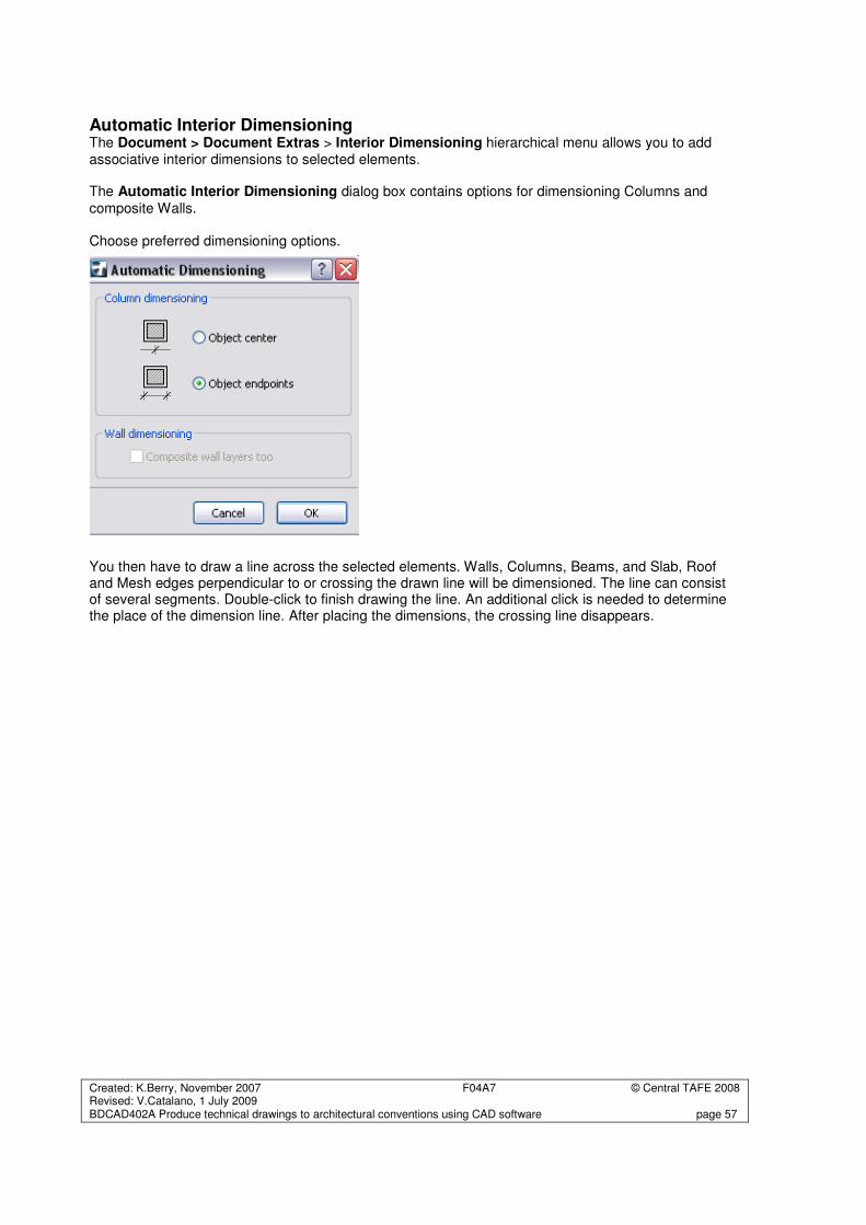
Created: K.Berry, November 2007 F04A7 © Central TAFE 2008 Revised: V.Catalano, 1 July 2009 BDCAD402A Produce technical drawings to architectural conventions using CAD software page 57
Automatic Interior Dimensioning The Document > Document Extras > Interior Dimensioning hierarchical menu allows you to add associative interior dimensions to selected elements. The Automatic Interior Dimensioning dialog box contains options for dimensioning Columns and
composite Walls.
Choose preferred dimensioning options.
You then have to draw a line across the selected elements. Walls, Columns, Beams, and Slab, Roof and Mesh edges perpendicular to or crossing the drawn line will be dimensioned. The line can consist of several segments. Double-click to finish drawing the line. An additional click is needed to determine the place of the dimension line. After placing the dimensions, the crossing line disappears.
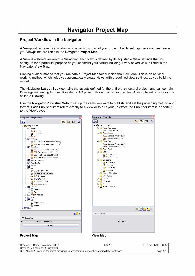
Created: K.Berry, November 2007 F04A7 © Central TAFE 2008 Revised: V.Catalano, 1 July 2009 BDCAD402A Produce technical drawings to architectural conventions using CAD software page 58
Navigator Project Map
Project Workflow in the Navigator A Viewpoint represents a window onto a particular part of your project, but its settings have not been saved yet. Viewpoints are listed in the Navigator Project Map. A View is a stored version of a Viewpoint; each view is defined by its adjustable View Settings that you configure for a particular purpose as you construct your Virtual Building. Every saved view is listed in the Navigator View Map. Cloning a folder means that you recreate a Project Map folder inside the View Map. This is an optional working method which helps you automatically create views, with predefined view settings, as you build the model. The Navigator Layout Book contains the layouts defined for the entire architectural project, and can contain Drawings originating from multiple ArchiCAD project files and other source files. A view placed on a Layout is called a Drawing. Use the Navigator Publisher Sets to set up the items you want to publish, and set the publishing method and
format. Each Publisher item refers directly to a View or to a Layout (in effect, the Publisher item is a shortcut to the View/Layout).
Project Map View Map
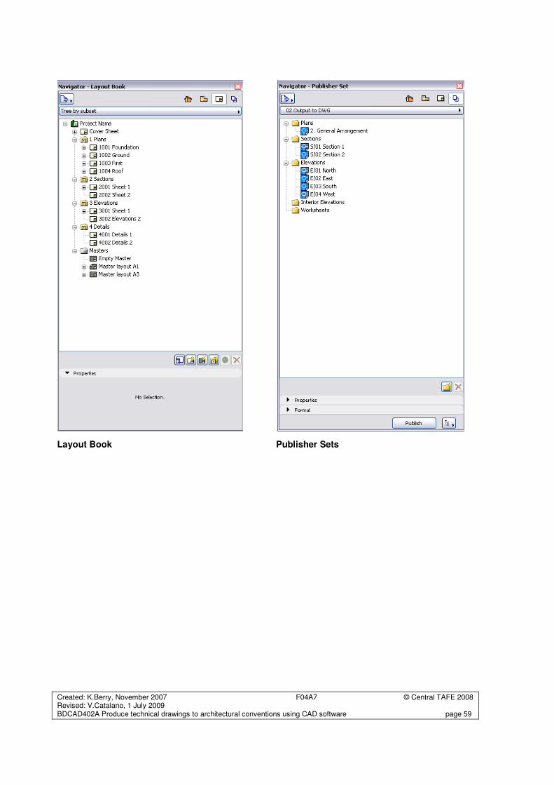
Created: K.Berry, November 2007 F04A7 © Central TAFE 2008 Revised: V.Catalano, 1 July 2009 BDCAD402A Produce technical drawings to architectural conventions using CAD software page 59
Layout Book Publisher Sets
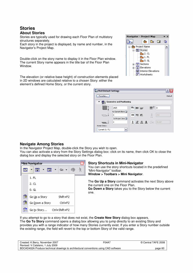
Created: K.Berry, November 2007 F04A7 © Central TAFE 2008 Revised: V.Catalano, 1 July 2009 BDCAD402A Produce technical drawings to architectural conventions using CAD software page 60
Stories About Stories Stories are typically used for drawing each Floor Plan of multistory structures separately. Each story in the project is displayed, by name and number, in the Navigator’s Project Map. Double-click on the story name to display it in the Floor Plan window. The current Story name appears in the title bar of the Floor Plan Window. The elevation (or relative base height) of construction elements placed in 2D windows are calculated relative to a chosen Story: either the element’s defined Home Story, or the current story.
Navigate Among Stories In the Navigator Project Map, double-click the Story you wish to open. You can also activate a story from the Story Settings dialog box: click on its name, then click OK to close the dialog box and display the selected story on the Floor Plan.
Story Shortcuts in Mini-Navigator You can use the story shortcuts located in the predefined “Mini-Navigator” toolbar. Window > Toolbars > Mini Navigator. The Go Up a Story command activates the next Story above the current one on the Floor Plan. Go Down a Story takes you to the Story below the current one.
If you attempt to go to a story that does not exist, the Create New Story dialog box appears. The Go To Story command opens a dialog box allowing you to jump directly to an existing Story and provides you with a range indicator of how many Stories currently exist. If you enter a Story number outside the existing range, the field will revert to the top or bottom Story of the valid range.
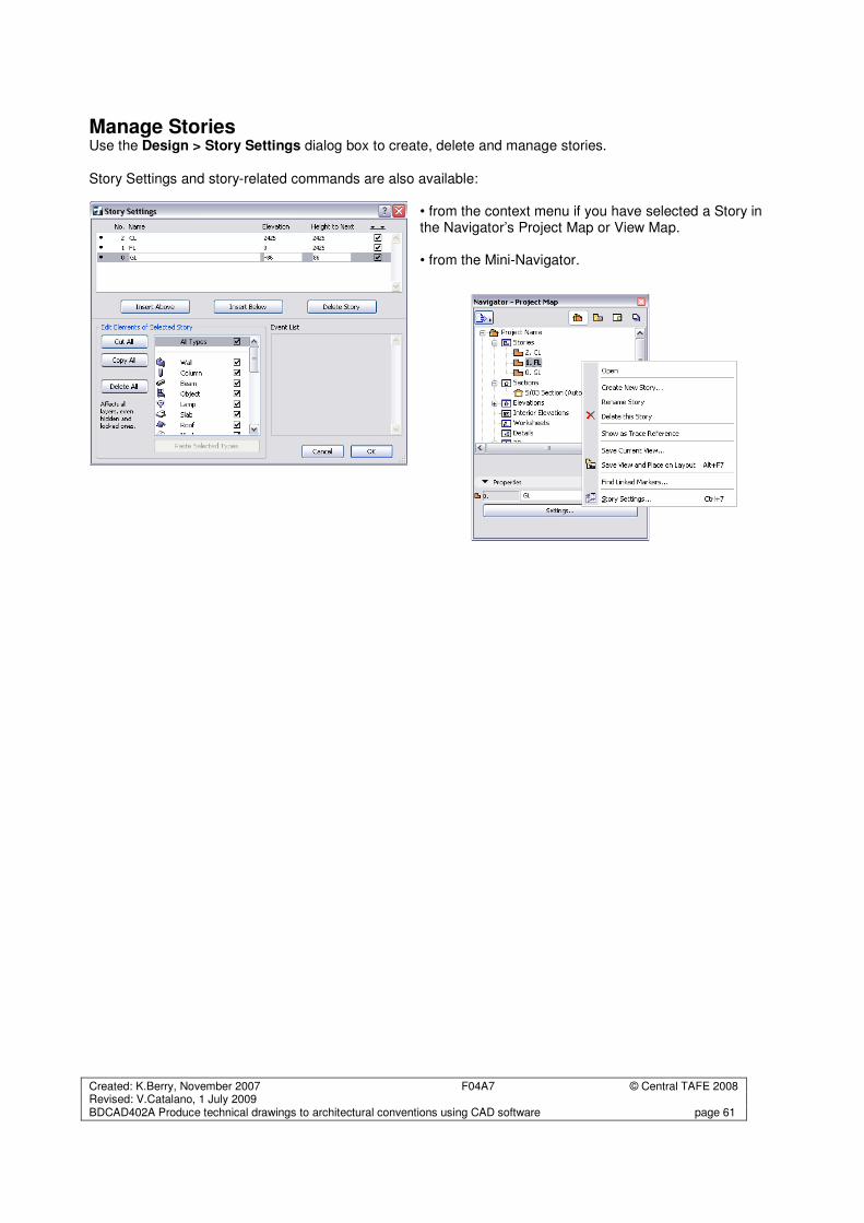
Created: K.Berry, November 2007 F04A7 © Central TAFE 2008 Revised: V.Catalano, 1 July 2009 BDCAD402A Produce technical drawings to architectural conventions using CAD software page 61
Manage Stories Use the Design > Story Settings dialog box to create, delete and manage stories.
Story Settings and story-related commands are also available:
• from the context menu if you have selected a Story in the Navigator’s Project Map or View Map. • from the Mini-Navigator.
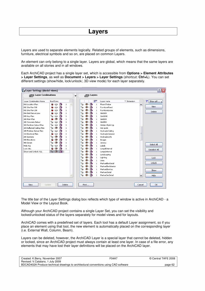
Created: K.Berry, November 2007 F04A7 © Central TAFE 2008 Revised: V.Catalano, 1 July 2009 BDCAD402A Produce technical drawings to architectural conventions using CAD software page 62
Layers Layers are used to separate elements logically. Related groups of elements, such as dimensions, furniture, electrical symbols and so on, are placed on common Layers. An element can only belong to a single layer. Layers are global, which means that the same layers are available on all stories and in all windows. Each ArchiCAD project has a single layer set, which is accessible from Options > Element Attributes > Layer Settings, as well as Document > Layers > Layer Settings (shortcut: Ctrl+L). You can set
different settings (show/hide, lock/unlock/, 3D view mode) for each layer separately.
The title bar of the Layer Settings dialog box reflects which type of window is active in ArchiCAD - a Model View or the Layout Book. Although your ArchiCAD project contains a single Layer Set, you can set the visibility and locked/unlocked status of the layers separately for model views and for layouts. ArchiCAD comes with a predefined set of layers. Each tool has a default Layer assignment, so if you place an element using that tool, the new element is automatically placed on the corresponding layer (i.e. External Wall, Column, Beam). Layers can be deleted, however, the ArchiCAD Layer is a special layer that cannot be deleted, hidden or locked, since an ArchiCAD project must always contain at least one layer. In case of a file error, any elements that may have lost their layer definitions will be placed on the ArchiCAD layer.
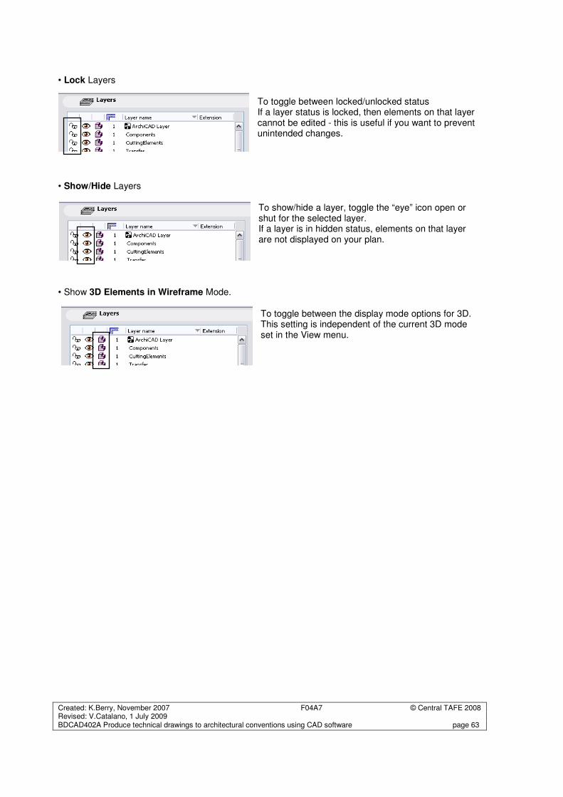
Created: K.Berry, November 2007 F04A7 © Central TAFE 2008 Revised: V.Catalano, 1 July 2009 BDCAD402A Produce technical drawings to architectural conventions using CAD software page 63
• Lock Layers To toggle between locked/unlocked status If a layer status is locked, then elements on that layer cannot be edited - this is useful if you want to prevent unintended changes.
• Show/Hide Layers
To show/hide a layer, toggle the “eye” icon open or shut for the selected layer. If a layer is in hidden status, elements on that layer are not displayed on your plan.
• Show 3D Elements in Wireframe Mode.
To toggle between the display mode options for 3D. This setting is independent of the current 3D mode set in the View menu.


![7E300 [Auto]CAD Basics: Foundations and 2D drawings 7E300 International CA(A)D-course](https://img.pdfslide.us/doc/110x75/56649d595503460f94a38e92/7e300-autocad-basics-foundations-and-2d-drawings-7e300-international-caad-course.jpg)