Embed Size (px)
Citation preview

BIM models generation from 2D CAD drawings and 3D scans: an analysis of challenges and opportunities for AEC practitioners
H. Barki1, F. Fadli1, A. Shaat2, P. Boguslawski3 & L. Mahdjoubi3 1Department of Architecture and Urban Planning, College of Engineering, Qatar University, Qatar 2MZ & Partners Architectural & Engineering Consultancy, Qatar 3Department of Architecture and the Built Environment, University of the West of England, UK
Abstract
Despite the recent and significant developments of BIM tools, available evidence reveals that current trends in BIM are tailored towards the design and construction phases of new projects, while most of the already existing projects, traditionally designed through CAD approaches, could hugely benefit from BIM integration. Automatic capture and conversion of CAD data into BIM models has remained a challenge. So far basic approaches ensuring either functional correctness or visual accuracy were advocated, but with limited success. In this paper, we propose a case study approach to examine the challenges and potential solutions of automatic BIM data capture and reconstruction of an existing skyscraper in Qatar – for which the construction phase has been achieved through traditional CAD design, using available as-built 2D CAD drawings and emerging data capture techniques such as 3D laser scanning and photogrammetry. The research targets BIM reconstruction for emergency preparedness and also seeks to address the strengths and limitations of available BIM reconstruction solutions of existing structures. Finally, we elaborate on future work directions that aim to speed-up the BIM generation process, as well as to add some automation capabilities to it. Keywords: 3D capture, Capture-to-BIM, CAD-to-BIM, laser scanning, photogrammetry, BIM reconstruction.
www.witpress.com, ISSN 1743-3509 (on-line) WIT Transactions on The Built Environment, Vol 149, © 2015 WIT Press
Building Information Modelling (BIM) in Design, Construction and Operations 369
doi:10.2495/BIM150311
1 Introduction to CAD and Capture to BIM
Building Information Modelling (BIM) is an innovative process and approach aiming to improve the management of Architecture, Engineering and Construction (AEC) projects [1]. Through the provision of intelligent concepts and objects, it helps AEC practitioners for developing efficient synchronization and harmonization of the different project aspects and steps [2], necessary for the unification of the design approaches, and guaranteeing the consistency and coordination of the project data among project stakeholders, regardless of the design updates, and leading to substantial benefits including cost reduction, time saving, etc. [3]. BIM is a recent approach that aims to complement or supersede traditional CAD design for the management of AEC projects. The current state of the art [4–6] shows that it is much easier to achieve BIM for new projects than for already existing ones, as the latter may be either undocumented or documented only through traditional non-BIM approaches, for which the incorporation of the existing models and data into BIM systems remains a challenge. This is a big concern when one considers that many countries have realized the importance of BIM and are initiating BIM reforms and pushing towards its adoption by putting strict deadlines, e.g. 2016 for UK [6]. In order to benefit from BIM for existing projects, one has to find automated or semi-automated ways to convert or incorporate any existing building data into a BIM system. Unfortunately, the capture and conversion of building data into BIM is still a big challenge. For documented projects, it is natural to think about exploiting CAD data and extracting BIM from it, while for undocumented projects, the trend goes towards the usage of data capture. Surprisingly, despite the fact that most of the existing buildings have been managed through CAD approaches, CAD-to-BIM conversion has retained little attention among researchers. Usually, CAD data is used as a footprint that is imported into 3D BIM software, where the BIM system creation is done manually through 3D sketching. Depending on the BIM system purposes, such manual conversion may target either functional correctness or visual accuracy [7]. Thanks to the recent developments in capture hardware, it is now possible to collect information about a scene in a cheap and precise manner. This ability induced the emergence of Capture-to-BIM approach which targets the automatic generation of BIM systems for (existing or under-construction) projects, by first extracting useful knowledge from the captured data through the usage of various shape descriptors [8, 9] and then converting that knowledge and incorporating it into BIM systems. Unfortunately, until now, many challenges need to be tackled before one can achieve an automated Capture-to-BIM generation. Most of the knowledge extraction approaches deal only with one or some aspects of the knowledge extraction task. For instance, a method has been proposed in [10] for the automatic recognition of simple CAD objects (columns and planar objects) but requires an a priori knowledge about the recognized model. Similar and related work focusing on fitting range data to simple CAD primitives (spheres, cylinders, and cuboids) can be found in [11, 12]. Based on a shape grammar, a 3D indoor
www.witpress.com, ISSN 1743-3509 (on-line) WIT Transactions on The Built Environment, Vol 149, © 2015 WIT Press
370 Building Information Modelling (BIM) in Design, Construction and Operations
scene modelling method has been presented in [13], where scenes were modelled by iteratively manipulating cuboid shapes. This method has been successfully applied to real point clouds but seems to be limited to basic scenes exhibiting cubical rooms. Starting from LiDAR data and operating at a larger scale, a method using recursive minimum bounding rectangles has been proposed in [14] for the automatic reconstruction of digital building models exhibiting right-angled corners. Other object recognition and knowledge extraction approaches used in the context of building and scene modelling may be found in [15, 16], just to cite a few. On the other hand, an important limitation of the current Capture-to-BIM state of the art concerns the automatic integration of the knowledge extracted from the raw data into a BIM system (managed by a specific data format or specific software), as this subtask has not retained much of the research attention, compared to the large literature available for object recognition. Based on the aforementioned CAD-to-BIM and Capture-to-BIM pros and cons discussions, the existing literature shows that CAD-to-BIM usage remained superficial in the sense that no automatic approaches have been proposed (CAD drawings used as original footprints). On the other hand, the trend goes towards the usage of the advanced capture techniques to achieve Capture-to-BIM tasks. The usage of CAD approaches is limited to documented projects only and CAD information may be outdated, unreliable, and may also lack details that are crucial for a particular application. In contrast, 3D capture overcomes the aforementioned CAD modelling limitations as it handles undocumented projects, provides an up-to-date source of information about a facility, and allows capturing more details than what can be found in CAD drawings. Furthermore, advanced capture techniques may currently constitute the only way to capture dynamic facility information which cannot be encoded into CAD drawings. When it comes to time and technical skills considerations, advanced capture techniques require less time and less technical qualifications for data acquisition as modern capture devices are user-friendly, can be handled in a short time, and allow capturing large amounts of data in seconds. On the other hand, CAD modelling has a steep learning curve, is usually an error prone, fastidious, and time consuming task, especially for complex projects (cf. section 4.1). For small budgets, CAD modelling requiring cheap software may be the unique modelling solution as 3D capture requires expensive equipment, for which the price decrease didn’t follow the rapid drop of other electronic devices. In a recent work [17], we have reviewed 3D data capture techniques and showed that an ideal technology doesn’t exist for an application domain, even for ours (BIM for emergency preparedness). While laser scanning excels in accurately capturing the spatial configuration of a scene, photogrammetry performs better when it comes to extracting visual information like texture and colours. The conclusions drawn by this study motivate us to combine the usage of laser scanning and photogrammetry for the 3D scene capture, in order to benefit from both approaches and to overcome their limitations, in addition to exploiting the already existing CAD drawings providing valuable as-built information about our case study building.
www.witpress.com, ISSN 1743-3509 (on-line) WIT Transactions on The Built Environment, Vol 149, © 2015 WIT Press
Building Information Modelling (BIM) in Design, Construction and Operations 371
In the sequel, we will first introduce in section 2 our case study building for which we are building a BIM system for future emergency preparedness purposes. Then, we briefly review the preliminary data we have (as-built plans) and discuss the data capture technology we are using in this study. Finally, throughout our concrete study example, we discuss the BIM system creation steps we have performed, in addition to examining the challenges we faced and proposing potential solutions or automating some tasks.
2 Overview of the case study building
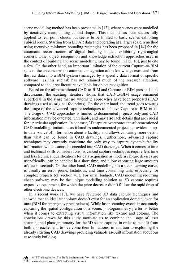
The main case study of this investigation is a high-rise tower located in the Westbay area of Doha, the capital of the state of Qatar (Figure 1). The tower has been designed by “MZ & Partners Architectural & Engineering Consultancy”, which is involved in our current project as a member of the steering committee. The tower is at the latter fit-out stages and it is composed of 4 basement levels, 1 ground level, and 50 recreational and office levels [18]. The tower levels (ground–50th) are arranged to host office floors (4th–46th), recreational spaces (47th–48th) which have been converted to VIP offices, and technical floors (49th–50th).
Figure 1: A view of the case study tower (taken from http://www.skyscrapercenter.com/doha/world-trade-center-doha/ 9918/).
3 Information acquisition from the tower
A major task of our work would be to gather information about the tower and its environment and to facilitate the access to it. By its nature, the problem at hand is a mix of 2D (facility architectural plans) and 3D (structure of the buildings, behaviour of persons within them, etc.).
www.witpress.com, ISSN 1743-3509 (on-line) WIT Transactions on The Built Environment, Vol 149, © 2015 WIT Press
372 Building Information Modelling (BIM) in Design, Construction and Operations
3.1 CAD information
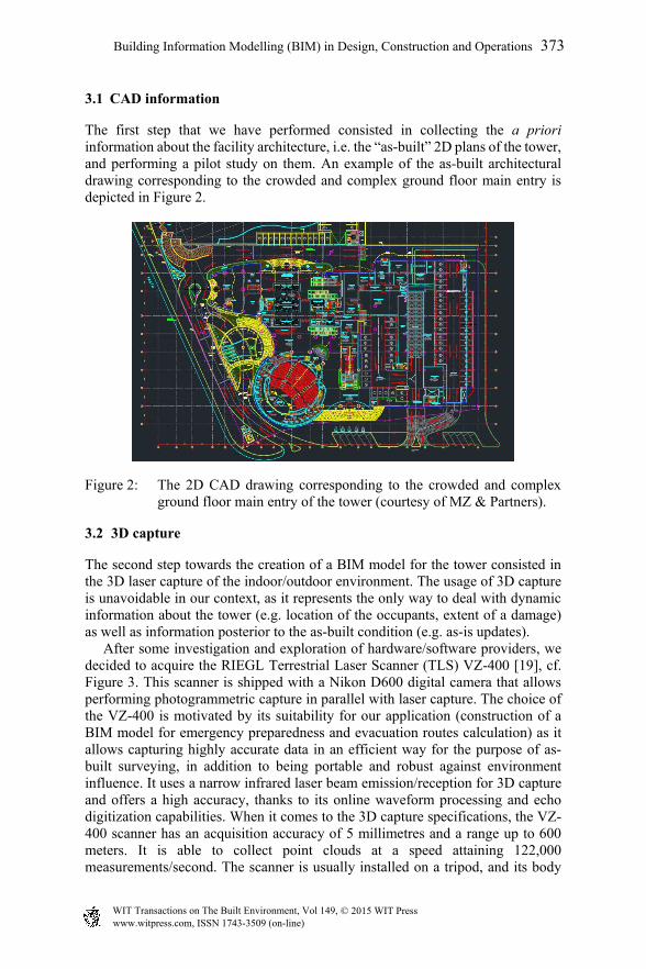
The first step that we have performed consisted in collecting the a priori information about the facility architecture, i.e. the “as-built” 2D plans of the tower, and performing a pilot study on them. An example of the as-built architectural drawing corresponding to the crowded and complex ground floor main entry is depicted in Figure 2.
Figure 2: The 2D CAD drawing corresponding to the crowded and complex ground floor main entry of the tower (courtesy of MZ & Partners).
3.2 3D capture
The second step towards the creation of a BIM model for the tower consisted in the 3D laser capture of the indoor/outdoor environment. The usage of 3D capture is unavoidable in our context, as it represents the only way to deal with dynamic information about the tower (e.g. location of the occupants, extent of a damage) as well as information posterior to the as-built condition (e.g. as-is updates). After some investigation and exploration of hardware/software providers, we decided to acquire the RIEGL Terrestrial Laser Scanner (TLS) VZ-400 [19], cf. Figure 3. This scanner is shipped with a Nikon D600 digital camera that allows performing photogrammetric capture in parallel with laser capture. The choice of the VZ-400 is motivated by its suitability for our application (construction of a BIM model for emergency preparedness and evacuation routes calculation) as it allows capturing highly accurate data in an efficient way for the purpose of as-built surveying, in addition to being portable and robust against environment influence. It uses a narrow infrared laser beam emission/reception for 3D capture and offers a high accuracy, thanks to its online waveform processing and echo digitization capabilities. When it comes to the 3D capture specifications, the VZ-400 scanner has an acquisition accuracy of 5 millimetres and a range up to 600 meters. It is able to collect point clouds at a speed attaining 122,000 measurements/second. The scanner is usually installed on a tripod, and its body
www.witpress.com, ISSN 1743-3509 (on-line) WIT Transactions on The Built Environment, Vol 149, © 2015 WIT Press
Building Information Modelling (BIM) in Design, Construction and Operations 373
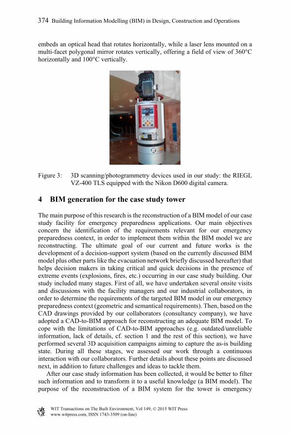
embeds an optical head that rotates horizontally, while a laser lens mounted on a multi-facet polygonal mirror rotates vertically, offering a field of view of 360°C horizontally and 100°C vertically.
Figure 3: 3D scanning/photogrammetry devices used in our study: the RIEGL VZ-400 TLS equipped with the Nikon D600 digital camera.
4 BIM generation for the case study tower
The main purpose of this research is the reconstruction of a BIM model of our case study facility for emergency preparedness applications. Our main objectives concern the identification of the requirements relevant for our emergency preparedness context, in order to implement them within the BIM model we are reconstructing. The ultimate goal of our current and future works is the development of a decision-support system (based on the currently discussed BIM model plus other parts like the evacuation network briefly discussed hereafter) that helps decision makers in taking critical and quick decisions in the presence of extreme events (explosions, fires, etc.) occurring in our case study building. Our study included many stages. First of all, we have undertaken several onsite visits and discussions with the facility managers and our industrial collaborators, in order to determine the requirements of the targeted BIM model in our emergency preparedness context (geometric and semantical requirements). Then, based on the CAD drawings provided by our collaborators (consultancy company), we have adopted a CAD-to-BIM approach for reconstructing an adequate BIM model. To cope with the limitations of CAD-to-BIM approaches (e.g. outdated/unreliable information, lack of details, cf. section 1 and the rest of this section), we have performed several 3D acquisition campaigns aiming to capture the as-is building state. During all these stages, we assessed our work through a continuous interaction with our collaborators. Further details about these points are discussed next, in addition to future challenges and ideas to tackle them. After our case study information has been collected, it would be better to filter such information and to transform it to a useful knowledge (a BIM model). The purpose of the reconstruction of a BIM system for the tower is emergency
www.witpress.com, ISSN 1743-3509 (on-line) WIT Transactions on The Built Environment, Vol 149, © 2015 WIT Press
374 Building Information Modelling (BIM) in Design, Construction and Operations
preparedness, where evacuation routes will be calculated and people guided through safest paths in case of extreme events. Such a model has to provide relevant information in this regard. Besides the building information capture step, the modelled system has to provide two main aspects of knowledge about the facility: geometric/spatial configuration of the building, and the necessary semantics decorating or enriching the building features. The capture of the facility information and the extraction of the relevant knowledge are discussed hereafter. In this study, we adopted Autodesk Revit as the BIM reconstruction environment or tool. Our choice is motivated by the following reasons: (1) Revit is the primary BIM tool used by our industrial collaborators who designed the building and provided us with the as-built CAD drawings, (2) Revit has the most important market share, meaning that the BIM model composing our emergency decision support system will have better chances to be adopted by the facility manager and that its adaptation or generalization to other facilities will reach a large percentage of future clients, (3) Revit allows combining CAD data, BIM data, and 3D capture data making it a central tool for our research, and (4) the emergency preparedness decision support system we are targeting is developed in two parts, the first part being the actually discussed BIM model, while the second one is the emergency navigation network which is computed from the BIM model after the latter has been exported to an adequate gbXML format, a task for which Revit excels. Details about the second part (navigation network) of our system and Revit-gbXML usage can be found in [17].
4.1 Geometric/spatial BIM information
Encoding the geometric information of the facility is an essential task as the evacuation routes are calculated based on the former. Such routes can be seen as the skeletons of the indoor spaces composing the building. In order to capture the geometry of the tower, we have exploited both CAD drawings and 3D laser capture. First of all, we have studied the CAD drawings offered to us in order to determine which geometric information to include and which information can be safely ignored, in order to keep the BIM system as simple as possible, while providing all required information. In our context, the geometry/spatial requirement have been identified to coincide with the encoding of the geometry (location and dimensions) of the building main elements, which include doors, walls, windows, and columns. Other elements or decorations were ignored as they do not influence the evacuation network calculation. The main difficulties arising during this preliminary CAD study, which may take many weeks depending on the drawings complexity and the building size, concern the observed discrepancy of the drawings and the manual extraction/edition of CAD/BIM information. Regarding the first issue, as many subcontractors have been involved in the design stage of the tower, it was not easy to deal with the varying conventions and notations used by these subcontractors. For example and just to cite a few of them, some building elements were not documented in the CAD drawings at all (e.g. structural walls), others were documented in the schedules without being actually used in the corresponding drawings, and for some element families like doors, the
www.witpress.com, ISSN 1743-3509 (on-line) WIT Transactions on The Built Environment, Vol 149, © 2015 WIT Press
Building Information Modelling (BIM) in Design, Construction and Operations 375
same element type (or unique reference in schedules) had different conflicting documentations and parameters (e.g. different width/height parameters) among different drawings. These concerns raise two questions: (1) how to retrieve the information of undocumented elements and (2) which documentation to follow among the conflicting ones. To answer the first question, we had to manually measure the geometry of the undocumented elements (columns) and report it in the created BIM elements. The solution we found the most appropriate for the second question about conflicting documentations for the same element type was to consider the most often encountered documentation. However, even if this choice seems the most logic and natural one, it may affect the evacuation network computations. To overcome this issue, we decided to encode the error of the geometry measurements as part of the concerned BIM elements themselves and to thus allow accounted for such errors during the evacuation network computations. The second issue concerns the manual extraction of CAD data and its manual incorporation into the BIM system. Such a widely used conversion strategy is error prone, fastidious, exhausting, and time consuming (many months for building like the one considered in this paper). The manual conversion wide spread is justified by the absence of automatic or semi-automatic approaches. A future work alternative that we propose in this sense is to take benefit from the programmable interfaces of the recent CAD and BIM software, in order to guide this process, at least by allowing some user interaction, as fully automating it seems to be impossible, due to CAD design deficiencies (absence of explicit links between design geometry and semantics). Such an approach may reduce the time and cost of CAD-to-BIM switch. Also regarding geometric information acquisition, we have performed several 3D laser/photogrammetric captures as the CAD drawings only encode the as-built configurations. Depending on the complexity of a particular building level (geometry, presence of obstacles), the necessary time for capturing the corresponding as-is information may vary from half a day (4–5 hours) to one day or more, and comprises the time necessary for positioning reflectors, calibrating the scanner/camera, capturing, and moving the scanner among the different scan positions. Other factors affecting the capture time include the used capture resolution and the field experience of the operator. For instance, the capture of atypical floor required 2 operators, 4 hours, and 12 scan positions, while the capture of the relevant areas of the crowded ground floor of Figure 2 took 2 days. For all our capture campaigns and because high scanning resolution is not necessary for our emergency preparedness application and the level of detail we want to reproduce, we adopted an average resolution scan pattern (panorama 40) of the TLS VZ-400 that requires 3 minutes per scan position. Figure 4 depicts a captured point cloud sample. One of the encountered minor capture difficulties concerned the unavailability of indoor GPS positioning, as microwaves are influenced by the building structure. The captured data will be used alongside the CAD converted data, in order to account for as-is configuration by incrementally building the BIM system. One of the challenges we are addressing concerns the automatic detection of as-built and as-is differences. Even if it is possible to manually import the point cloud into BIM
www.witpress.com, ISSN 1743-3509 (on-line) WIT Transactions on The Built Environment, Vol 149, © 2015 WIT Press
376 Building Information Modelling (BIM) in Design, Construction and Operations
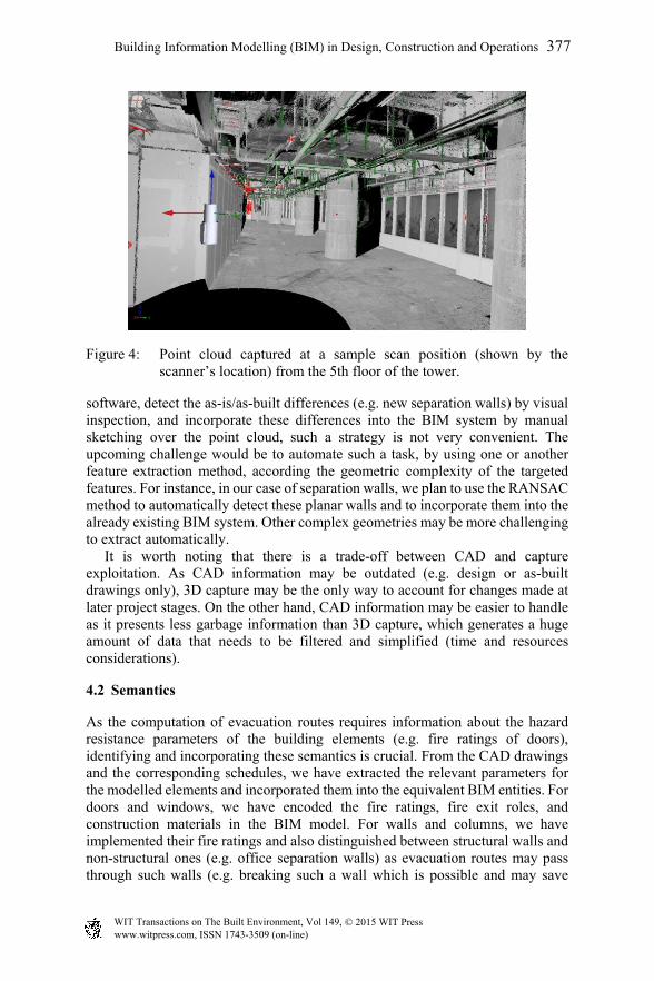
Figure 4: Point cloud captured at a sample scan position (shown by the scanner’s location) from the 5th floor of the tower.
software, detect the as-is/as-built differences (e.g. new separation walls) by visual inspection, and incorporate these differences into the BIM system by manual sketching over the point cloud, such a strategy is not very convenient. The upcoming challenge would be to automate such a task, by using one or another feature extraction method, according the geometric complexity of the targeted features. For instance, in our case of separation walls, we plan to use the RANSAC method to automatically detect these planar walls and to incorporate them into the already existing BIM system. Other complex geometries may be more challenging to extract automatically. It is worth noting that there is a trade-off between CAD and capture exploitation. As CAD information may be outdated (e.g. design or as-built drawings only), 3D capture may be the only way to account for changes made at later project stages. On the other hand, CAD information may be easier to handle as it presents less garbage information than 3D capture, which generates a huge amount of data that needs to be filtered and simplified (time and resources considerations).
4.2 Semantics
As the computation of evacuation routes requires information about the hazard resistance parameters of the building elements (e.g. fire ratings of doors), identifying and incorporating these semantics is crucial. From the CAD drawings and the corresponding schedules, we have extracted the relevant parameters for the modelled elements and incorporated them into the equivalent BIM entities. For doors and windows, we have encoded the fire ratings, fire exit roles, and construction materials in the BIM model. For walls and columns, we have implemented their fire ratings and also distinguished between structural walls and non-structural ones (e.g. office separation walls) as evacuation routes may pass through such walls (e.g. breaking such a wall which is possible and may save
www.witpress.com, ISSN 1743-3509 (on-line) WIT Transactions on The Built Environment, Vol 149, © 2015 WIT Press
Building Information Modelling (BIM) in Design, Construction and Operations 377
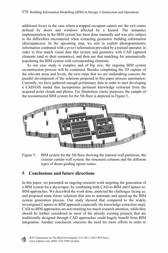
additional lives) in the case where a trapped occupant cannot use the exit routes defined by doors and windows affected by a hazard. The semantics implementation in the BIM system has been done manually and was also subject to the difficulties encountered when extracting geometric building information (discrepancies). In the upcoming step, we aim to exploit photogrammetric information combined with a priori information provided by a trained operator, in order to first match visual data like texture and geometry with CAD captured elements (and so their semantics), and then use that matching for automatically populating the BIM system with corresponding elements. As our case study is complex and of big size, the ongoing BIM system reconstruction process will be continued. Besides completing the 3D capture of the relevant areas and levels, the next steps that we are undertaking concern the parallel development of the solutions proposed in this paper process automation. Currently, we have gathered enough preliminary data in order to start developing a CAD/GIS model that incorporates pertinent knowledge extracted from the acquired point clouds and photos. For illustration clarity purposes, the sample of the reconstructed BIM system for the 5th floor is depicted in Figure 5.
Figure 5: BIM system for the 5th floor showing the internal wall partitions, the exterior curtain wall system, the structural columns and the different types of doors guiding egress routes.
5 Conclusions and future directions
In this paper, we presented an ongoing research work targeting the generation of a BIM system for a skyscraper, by combining both CAD-to-BIM and Capture-to-BIM approaches. We described the work done, analysed the challenges facing us, and proposed some future solutions that aim to automate and speed-up the BIM system generation process. Our study showed that compared to the widely investigated Capture-to BIM approach (especially the knowledge extraction step), CAD-to-BIM approaches are not retaining too much research attention, while they should be further considered as most of the already existing projects that are traditionally designed through CAD approaches could hugely benefit from BIM integration. Another conclusion concerns the need for more efforts in order to
www.witpress.com, ISSN 1743-3509 (on-line) WIT Transactions on The Built Environment, Vol 149, © 2015 WIT Press
378 Building Information Modelling (BIM) in Design, Construction and Operations
address the issue of integrating extracted knowledge into BIM systems, representing an important sub-task in Capture-to-BIM approaches. Based on this study, both CAD-to-BIM and Capture-to-BIM approaches present pros and cons, the choice of the adequate technology depends on many parameters, like the BIM system requirements (level of detail of the model and targeted application) and time and cost considerations. The recent trends recommend the usage of advanced capture technologies in situations where traditional CAD modelling reaches its limits and where cost considerations are not a major obstacle. As previously stated, an ideal capture technology cannot be unambiguously recommended for a particular application domain, but the combined usage of different technologies is preferred whenever possible, in order to combine their strengths and overcome their limitations.
Acknowledgements
This research/publication was made possible by a National Priority Research Program NPRP award (NPRP-06-1208-2-492) from the Qatar National Research Fund (a member of The Qatar Foundation). The statements made herein are solely the responsibility of the author(s). Note: Special thanks go to the building owner, the facility managers, and our industrial collaborators who made our site-visits and fieldwork successful.
References
[1] Eastman, C., Teicholz, P., Sacks, R. & Liston, K., BIM Handbook: A Guide to Building Information Modeling for Owners, Managers, Designers, Engineers and Contractors. Wiley Publishing, 2nd edition, 2011.
[2] Barlish, K. & Sullivan, K., How to measure the benefits of BIM – A case study approach. Automation in Construction, 24, pp. 149-159, 2012.
[3] Bryde, D., Broquetas, M. & Volm, J.M., The project benefits of building information modelling (BIM). International Journal of Project Management, 31(7), pp. 971-980, 2013.
[4] Volk, R., Stengel, J. & Schultmann, F., Building Information Modeling (BIM) for existing buildings – Literature review and future needs. Automation in Construction, 38, pp. 109-127, 2014.
[5] Arayici, Y. & Tah, J., Towards building information modelling for existing structures. Eleventh International Conference on Civil, Structural and Environmental Engineering Computing, Stirlingshire, UK, pp. 210-222, 2008.
[6] Eadie, R., Browne, M., Odeyinka, H., McKeown, C. & McNiff, S., BIM implementation throughout the UK construction project lifecycle: An analysis. Automation in Construction, 36, pp. 145-151, 2013.
[7] Grabowski, R., CAD & BIM: Is There A Free Pass? A Report on GRAPHISOFT ArchiCADs DWG Workflow. Technical report, ArchiCAD, 2010.
www.witpress.com, ISSN 1743-3509 (on-line) WIT Transactions on The Built Environment, Vol 149, © 2015 WIT Press
Building Information Modelling (BIM) in Design, Construction and Operations 379
[8] Loncaric, S., A survey of shape analysis techniques. Pattern Recognition, 31(8), pp. 983-1001, 1998.
[9] Zhang, D. & Lu, G., Review of shape representation and description techniques. Pattern Recognition, 37(1), pp. 1-19, 2004.
[10] Bosché, F. & Haas, C.T., Automated retrieval of 3D CAD model objects in construction range images. Automation in Construction, 17, pp. 499-512, 2008.
[11] Kwon, S.W., Bosché, F., Kim, C., Haas, C.T. & Liapi, K.A., Fitting range data to primitives for rapid local 3D modeling using sparse range point clouds. Automation in Construction, 13(1), pp. 67-81, 2004.
[12] Bosché, F., Automated recognition of 3D CAD model objects in laser scans and calculation of as-built dimensions for dimensional compliance control in construction. Advanced Engineering Informatics, 24(1), pp. 107-118, 2010.
[13] Khoshelham, K. & Díaz-Vilariño, L., 3D Modelling of Interior Spaces: Learning the Language of Indoor Architecture. ISPRS – International Archives of the Photogrammetry, Remote Sensing and Spatial Information Sciences, XL-5, pp. 321-326, 2014.
[14] Kwak, E. & Habib, A., Automatic representation and reconstruction of DBM from LiDAR data using Recursive Minimum Bounding Rectangle. ISPRS Journal of Photogrammetry and Remote Sensing, 93, pp. 171-191, 2014.
[15] Brilakis, I., Lourakis, M., Sacks, R., Savarese, S., Christodoulou, S., Teizer, J. & Makhmalbaf, A., Toward automated generation of parametric BIMs based on hybrid video and laser scanning data. Advanced Engineering Informatics, 24(4), pp. 456-465, 2010.
[16] Arayici, Y., An approach for real world data modelling with the 3D terrestrial laser scanner for built environment. Automation in Construction, 16(6), pp. 816-829, 2007.
[17] Fadli, F., Barki, H., Boguslawski, P. & Mahdjoubi, L., 3D scene capture: a comprehensive review of techniques and tools for efficient Life Cycle Analysis (LCA) and Emergency Preparedness (EP) applications. proceedings of the International Conference on Building Information Modelling (BIM) in Design, Constructions and Operations, 2015.
[18] MZ & Partners, World Trade Center (WTC) Tower – Doha: Project description, 2009.
[19] RIEGL Laser Measurement Systems, http://www.riegl.com/
www.witpress.com, ISSN 1743-3509 (on-line) WIT Transactions on The Built Environment, Vol 149, © 2015 WIT Press
380 Building Information Modelling (BIM) in Design, Construction and Operations