Embed Size (px)
Citation preview
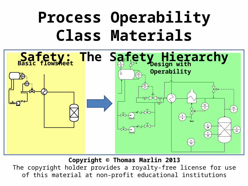
Process Operability Class MaterialsSafety: The Safety Hierarchy
Copyright © Thomas Marlin 2013The copyright holder provides a royalty-free license for use of this material at non-profit
educational institutions
FC1
LC1
FC
1
TC
1
TC
2
T
10
T
12
T
11
T
13
fuel
LC
1
L2
LAHLAL
F
4
Basic flowsheet Design with Operability
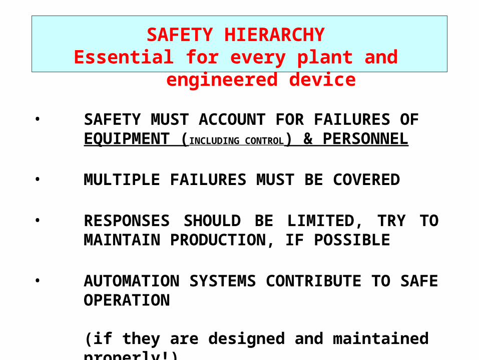
SAFETY HIERARCHYEssential for every plant and engineered device
• SAFETY MUST ACCOUNT FOR FAILURES OF EQUIPMENT (INCLUDING CONTROL) & PERSONNEL
• MULTIPLE FAILURES MUST BE COVERED
• RESPONSES SHOULD BE LIMITED, TRY TO MAINTAIN PRODUCTION, IF POSSIBLE
• AUTOMATION SYSTEMS CONTRIBUTE TO SAFE OPERATION
(if they are designed and maintained properly!)
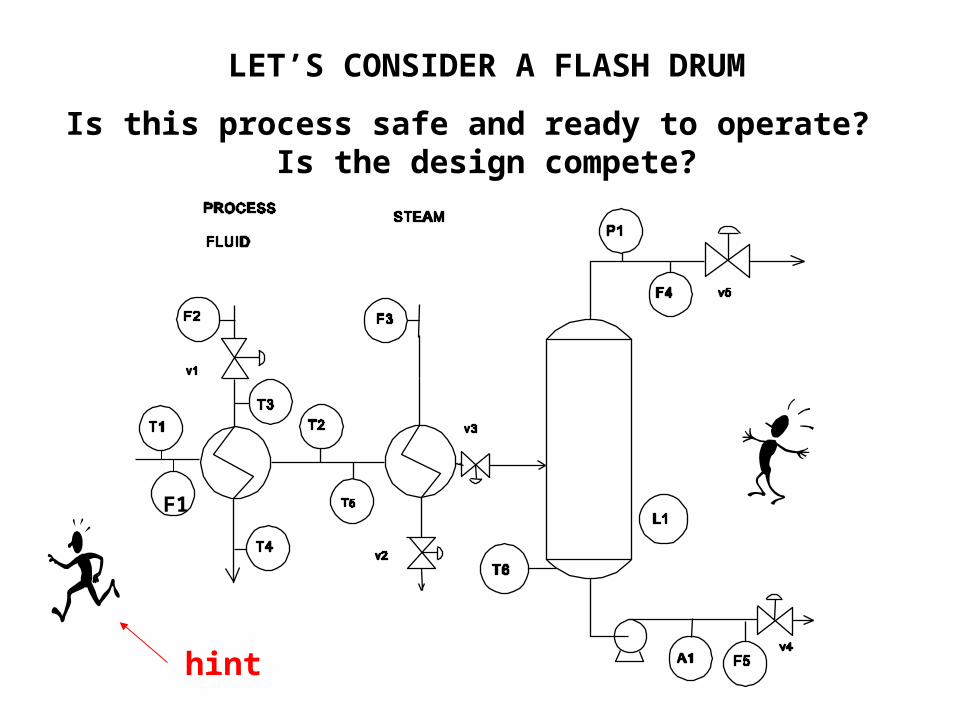
LET’S CONSIDER A FLASH DRUM
Is this process safe and ready to operate? Is the design compete?
F1
hint
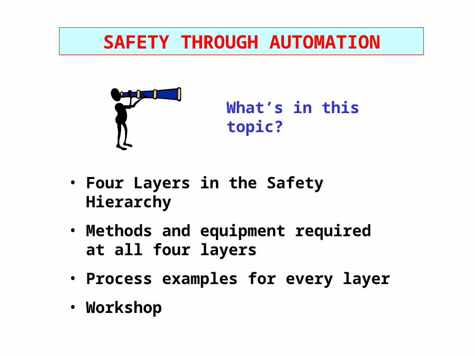
• Four Layers in the Safety Hierarchy
• Methods and equipment required at all four layers
• Process examples for every layer
• Workshop
What’s in this topic?
SAFETY THROUGH AUTOMATION
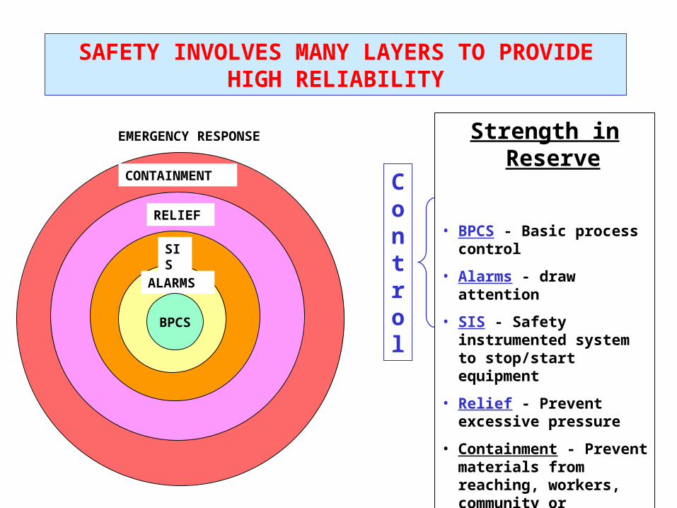
ALARMS
SIS
RELIEF
CONTAINMENT
EMERGENCY RESPONSE
BPCS
Strength in Reserve
• BPCS - Basic process control
• Alarms - draw attention
• SIS - Safety instrumented system to stop/start equipment
• Relief - Prevent excessive pressure
• Containment - Prevent materials from reaching, workers, community or environment
• Emergency Response - evacuation, fire fighting, health care, etc.
SAFETY INVOLVES MANY LAYERS TO PROVIDE HIGH RELIABILITY
Control
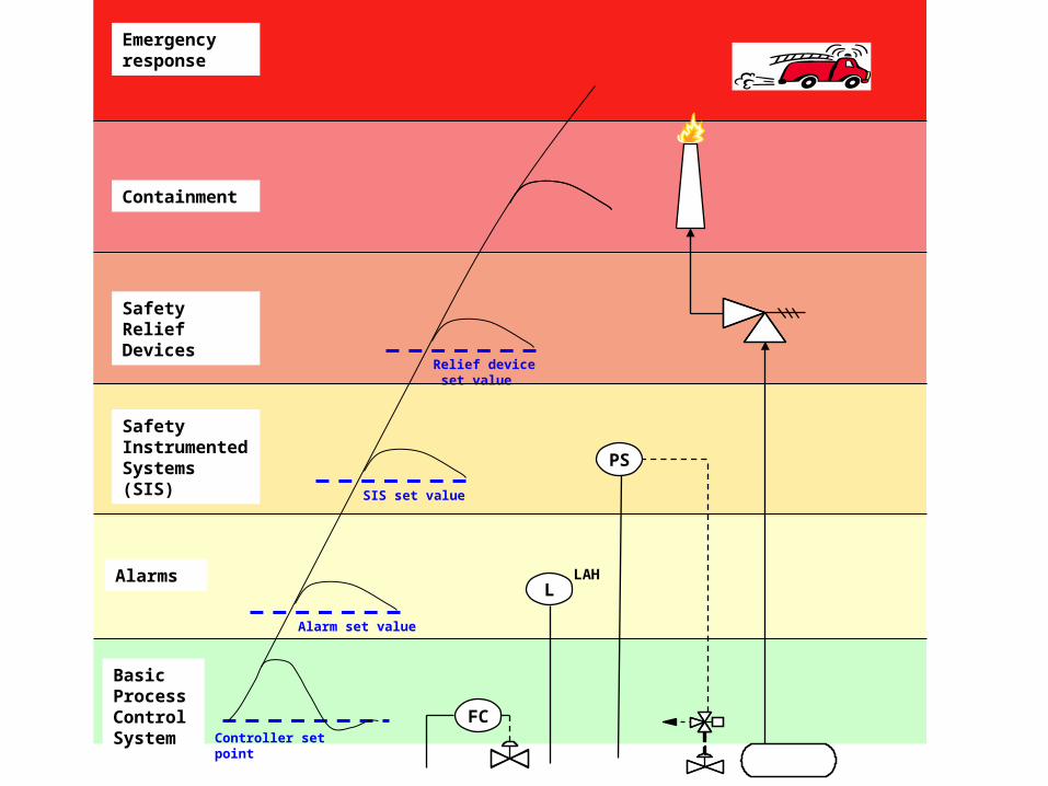
Basic Process Control System
Alarms
Controller set point
Alarm set value
Safety Instrumented Systems(SIS) SIS set value
Relief device set value
Safety Relief Devices
Containment
Emergency response
FC
LLAH
PS
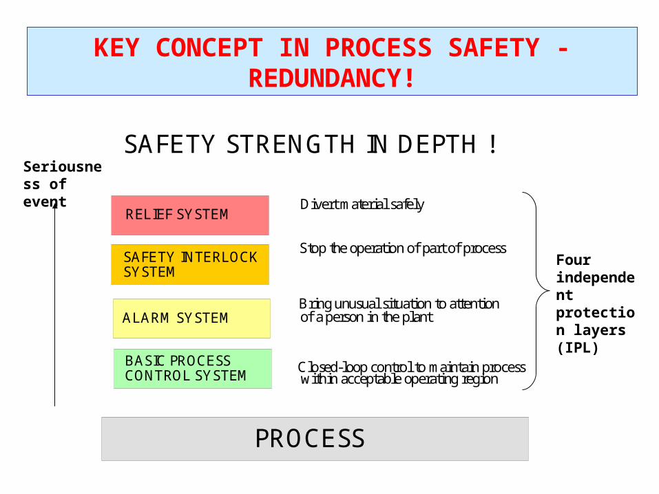
SAFETY STRENGTH IN DEPTH !
PROCESS
RELIEF SYSTEM
SAFETY INTERLOCK SYSTEM
ALARM SYSTEM
BASIC PROCESSCONTROL SYSTEM
Closed-loop control to maintain processwithin acceptable operating region
Bring unusual situation to attentionof a person in the plant
Stop the operation of part of process
Divert material safely
KEY CONCEPT IN PROCESS SAFETY - REDUNDANCY!
Seriousness of event
Four independent protection layers (IPL)
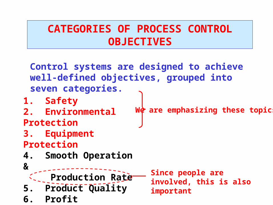
CATEGORIES OF PROCESS CONTROL OBJECTIVES
1. Safety2. Environmental Protection3. Equipment Protection4. Smooth Operation & Production Rate5. Product Quality6. Profit7. Monitoring & Diagnosis
We are emphasizing these topics
Since people are involved, this is also important
Control systems are designed to achieve well-defined objectives, grouped into seven categories.
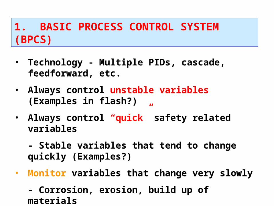
1. BASIC PROCESS CONTROL SYSTEM (BPCS)
• Technology - Multiple PIDs, cascade, feedforward, etc.
• Always control unstable variables (Examples in flash?)
• Always control “quick” safety related variables
- Stable variables that tend to change quickly (Examples?)
• Monitor variables that change very slowly
- Corrosion, erosion, build up of materials
• Provide safe response to critical instrumentation failures
- But, we use instrumentation in the BPCS?
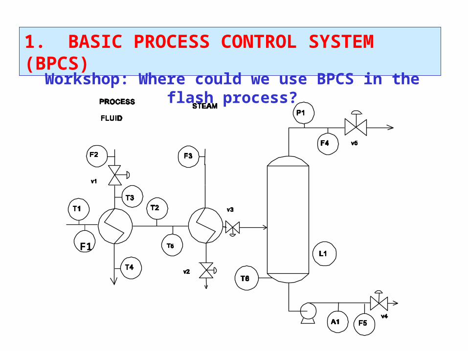
1. BASIC PROCESS CONTROL SYSTEM (BPCS)
Workshop: Where could we use BPCS in the flash process?
F1
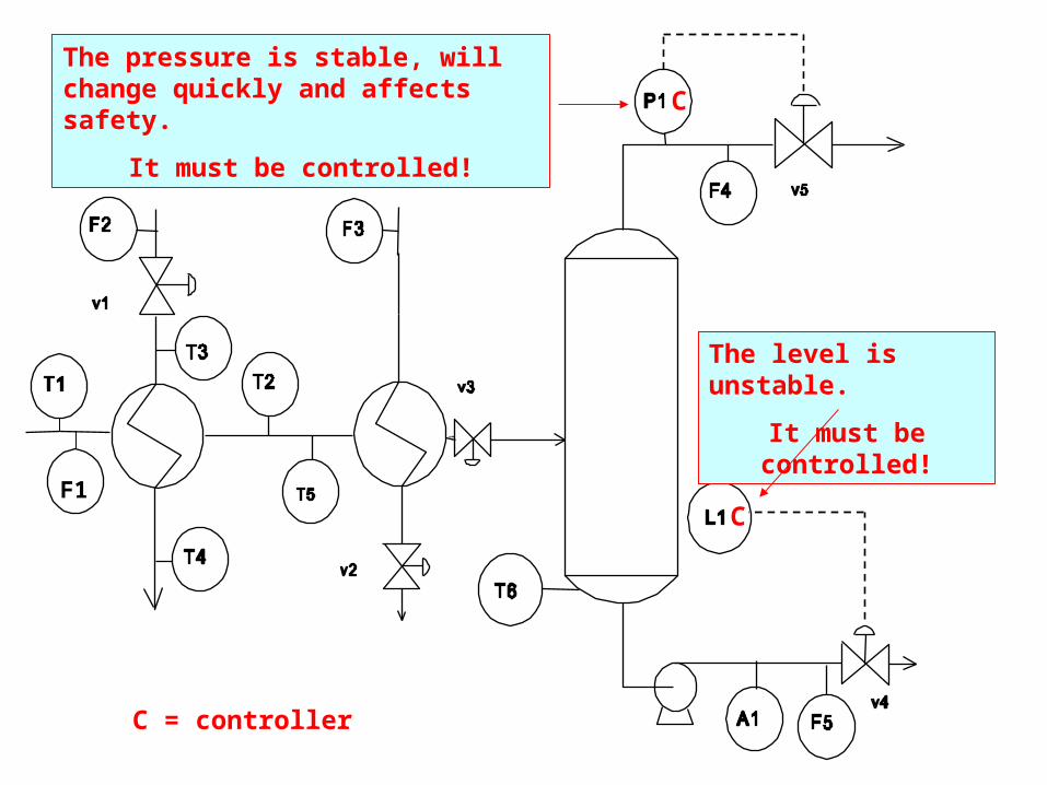
The level is unstable.
It must be controlled!
The pressure is stable, will change quickly and affects safety.
It must be controlled!
F1
C = controller
C
C
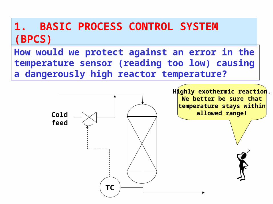
1. BASIC PROCESS CONTROL SYSTEM (BPCS)
How would we protect against an error in the temperature sensor (reading too low) causing a dangerously high reactor temperature?
TC
Coldfeed
Highly exothermic reaction.We better be sure that
temperature stays withinallowed range!
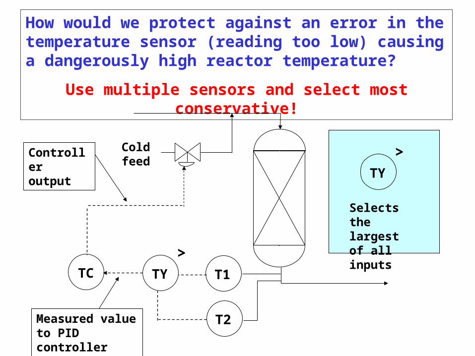
How would we protect against an error in the temperature sensor (reading too low) causing a dangerously high reactor temperature?
Use multiple sensors and select most conservative!
T1
Coldfeed
T2
TYTC
Measured valueto PID controller
Controlleroutput
>
TY
>
Selects the largest of all inputs
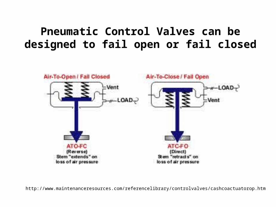
http://www.maintenanceresources.com/referencelibrary/controlvalves/cashcoactuatorop.htm
Pneumatic Control Valves can be designed to fail open or fail closed
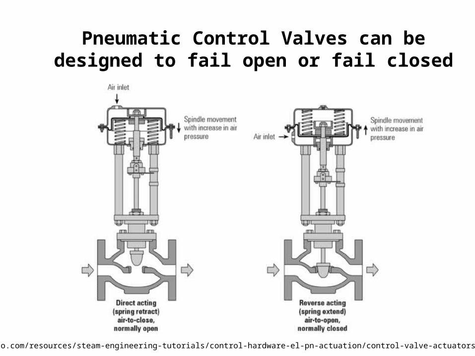
Pneumatic Control Valves can be designed to fail open or fail closed
http://www.spiraxsarco.com/resources/steam-engineering-tutorials/control-hardware-el-pn-actuation/control-valve-actuators-and-positioners.asp
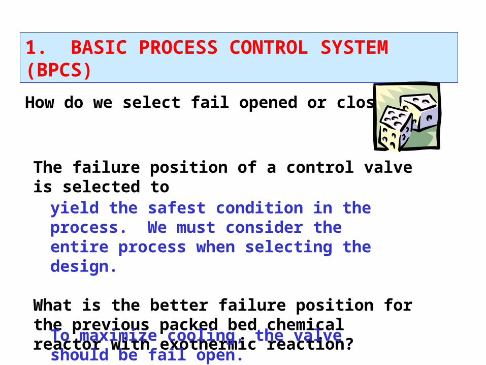
1. BASIC PROCESS CONTROL SYSTEM (BPCS)
How do we select fail opened or closed?
The failure position of a control valve is selected to
What is the better failure position for the previous packed bed chemical reactor with exothermic reaction?
yield the safest condition in the process. We must consider the entire process when selecting the design.
To maximize cooling, the valve should be fail open.
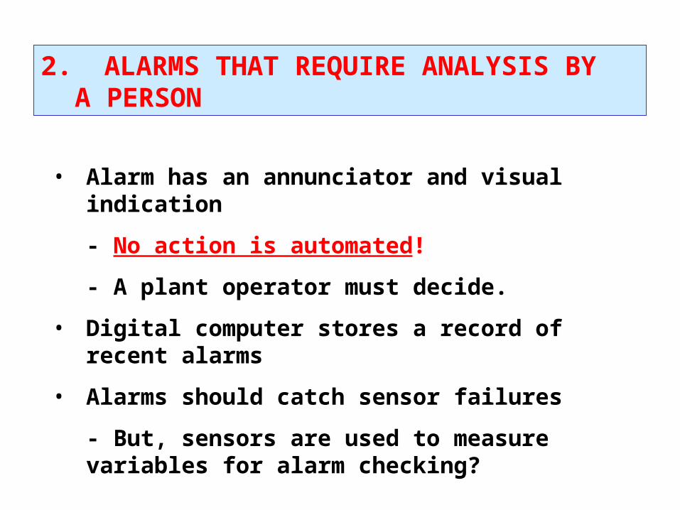
2. ALARMS THAT REQUIRE ANALYSIS BY A PERSON
• Alarm has an annunciator and visual indication
- No action is automated!
- A plant operator must decide.
• Digital computer stores a record of recent alarms
• Alarms should catch sensor failures
- But, sensors are used to measure variables for alarm checking?
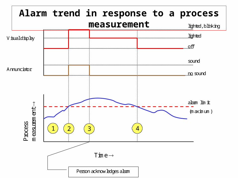
Time
Pro
cess
mea
sure
men
t
alarm limit
(maximum)
Annunciator
sound
no sound
off
lighted
lighted, blinking
Visual display
Person acknowledges alarm
1 2 3 4
Alarm trend in response to a process measurement
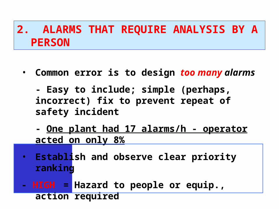
2. ALARMS THAT REQUIRE ANALYSIS BY A PERSON
• Common error is to design too many alarms
- Easy to include; simple (perhaps, incorrect) fix to prevent repeat of safety incident
- One plant had 17 alarms/h - operator acted on only 8%
• Establish and observe clear priority ranking
- HIGH = Hazard to people or equip., action required
- MEDIUM = Loss of $$, close monitoring required
- LOWLOW = investigate when time available
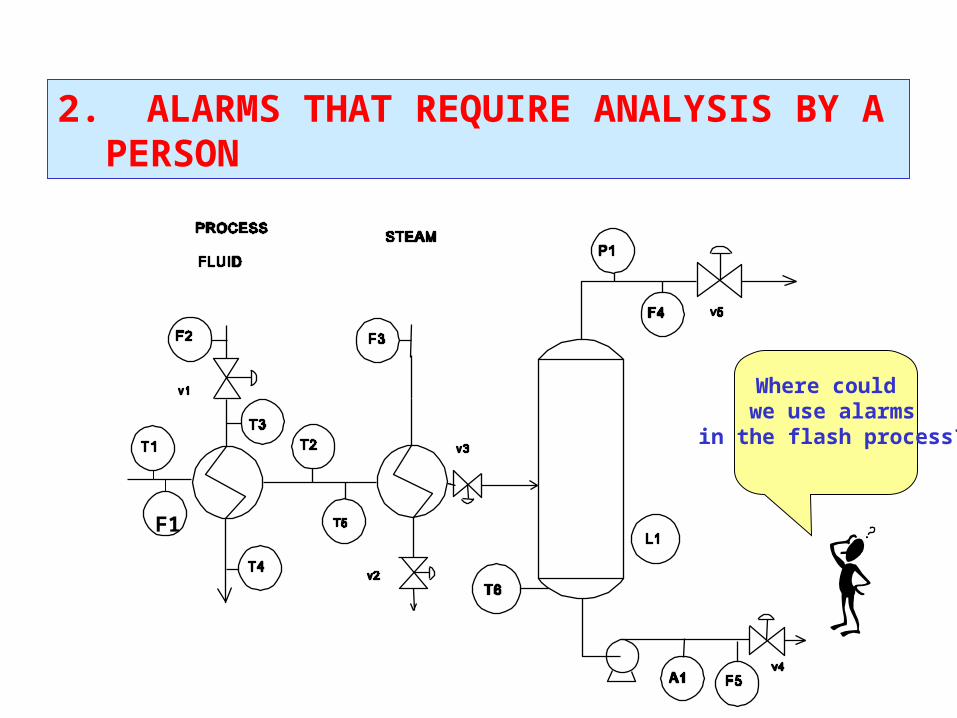
2. ALARMS THAT REQUIRE ANALYSIS BY A PERSON
F1
Where could we use alarms
in the flash process?
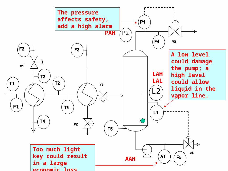
A low level could damage the pump; a high level could allow liquid in the vapor line.
The pressure affects safety, add a high alarm
F1
LAHLAL
Too much light key could result in a large economic loss
AAH
PAH P2
L2
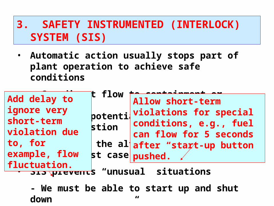
3. SAFETY INSTRUMENTED (INTERLOCK) SYSTEM (SIS)
• Automatic action usually stops part of plant operation to achieve safe conditions
- Can divert flow to containment or disposal- Can stop potentially hazardous process, e.g., combustion
• Capacity of the alternative process must be for “worst case”
• SIS prevents “unusual” situations
- We must be able to start up and shut down- Very fast “blips” might not be significant
Allow short-term violations for special conditions, e.g., fuel can flow for 5 seconds after “start-up button pushed.
Add delay to ignore very short-term violation due to, for example, flow fluctuation.
• Also called emergency shutdown system (ESS)
• SIS should respond properly to instrumentation failures
- But, instrumentation is required for SIS?
• Extreme corrective action is required and automated
- More aggressive than process control (BPCS)
• Alarm to operator when an SIS takes action
3. SAFETY INSTRUMENTED (INTERLOCK) SYSTEM (SIS)
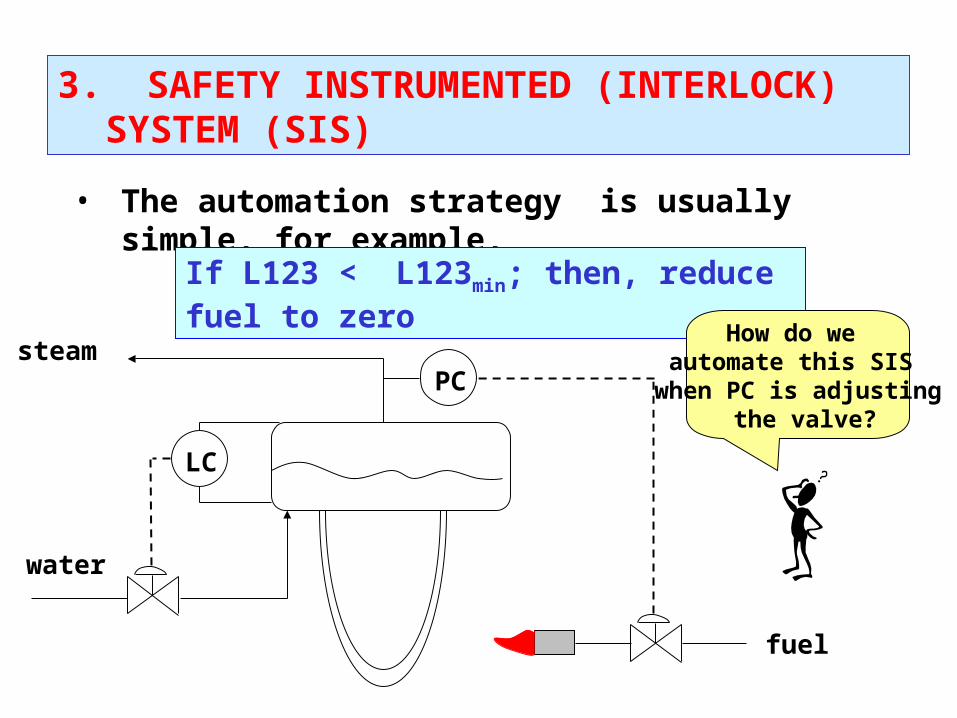
• The automation strategy is usually simple, for example,
If L123 < L123min; then, reduce fuel to zero
steam
water
LC
PC
fuel
How do we automate this SIS
when PC is adjusting the valve?
3. SAFETY INSTRUMENTED (INTERLOCK) SYSTEM (SIS)

If L123 < L123min; then, reduce fuel to zero
steam
water
LC
PC
fuel
LS s s
fc fc
15 psig
LS = level switch, note that separate sensor is used
s = solenoid valve (open/closed) fc = fail closed
Extra valve with tight shutoff
i/p
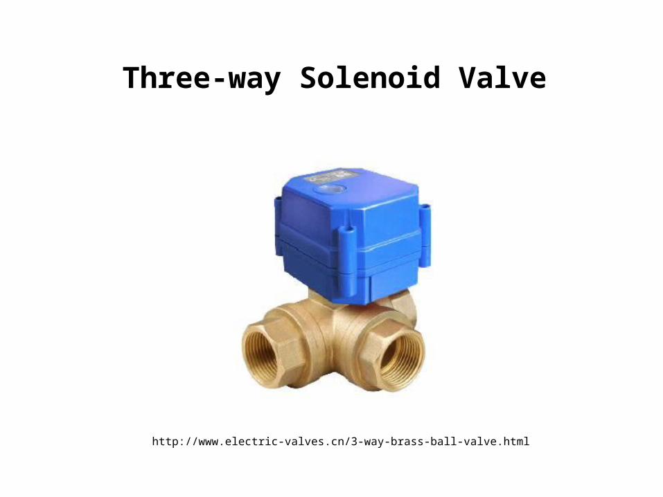
http://www.electric-valves.cn/3-way-brass-ball-valve.html
Three-way Solenoid Valve
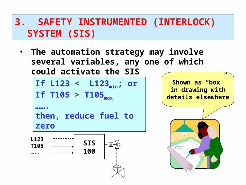
• The automation strategy may involve several variables, any one of which could activate the SIS
If L123 < L123min; orIf T105 > T105max
…….then, reduce fuel to zero
SIS100
L123T105…..
s
Shown as “box” in drawing with details elsewhere
3. SAFETY INSTRUMENTED (INTERLOCK) SYSTEM (SIS)
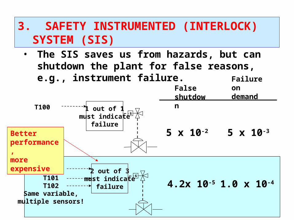
• The SIS saves us from hazards, but can shutdown the plant for false reasons, e.g., instrument failure.
1 out of 1 must indicate
failure
T100s
2 out of 3 must indicate
failure
T100T101T102
Same variable,multiple sensors!
s
Falseshutdown
Failure on demand
5 x 10-35 x 10-2
4.2x 10⁻⁵ 1.0 x 10⁻⁴
Better performance,more expensive
3. SAFETY INSTRUMENTED (INTERLOCK) SYSTEM (SIS)
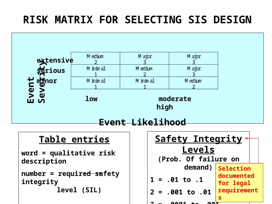
Medium2
Major3
Major3
Minimal1
Medium2
Major3
Minimal1
Minimal1
Medium2
low moderate high
Event Likelihood
Eve
nt
Sev
erit
y
extensive
serious
minor
Table entries
word = qualitative risk description
number = required safety integrity level (SIL)
Safety Integrity Levels(Prob. Of failure on demand)
1 = .01 to .1
2 = .001 to .01
3 = .0001 to .001
RISK MATRIX FOR SELECTING SIS DESIGN
Selection documented for legal requirements
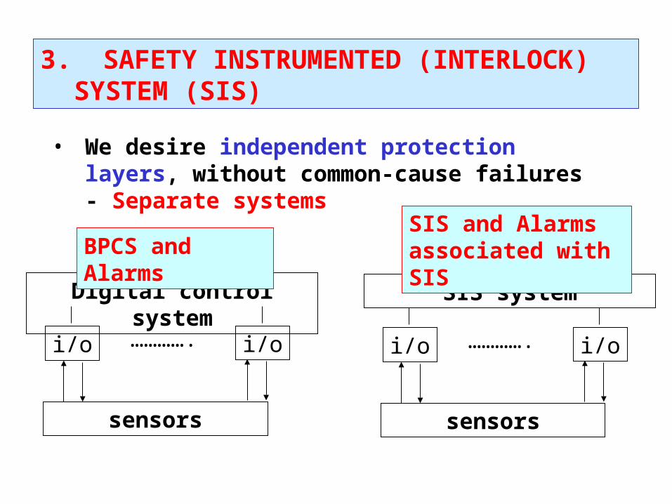
• We desire independent protection layers, without common-cause failures - Separate systems
sensors
SIS system
i/o i/o………….
sensors
Digital control system
i/o i/o………….
BPCS and Alarms SIS and Alarms associated with SIS
3. SAFETY INSTRUMENTED (INTERLOCK) SYSTEM (SIS)
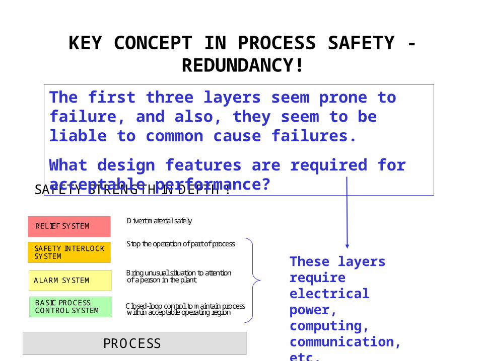
SAFETY STRENGTH IN DEPTH !
PROCESS
RELIEF SYSTEM
SAFETY INTERLOCK SYSTEM
ALARM SYSTEM
BASIC PROCESSCONTROL SYSTEM
Closed-loop control to maintain processwithin acceptable operating region
Bring unusual situation to attentionof a person in the plant
Stop the operation of part of process
Divert material safely
KEY CONCEPT IN PROCESS SAFETY - REDUNDANCY!
The first three layers seem prone to failure, and also, they seem to be liable to common cause failures.
What design features are required for acceptable performance?
These layers require electrical power, computing, communication, etc.
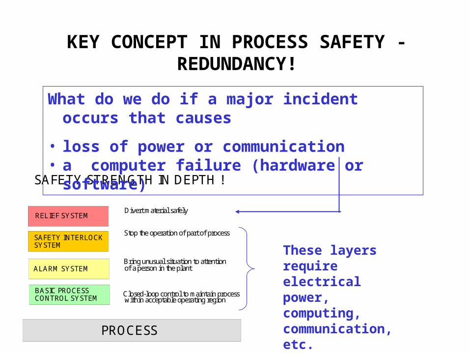
SAFETY STRENGTH IN DEPTH !
PROCESS
RELIEF SYSTEM
SAFETY INTERLOCK SYSTEM
ALARM SYSTEM
BASIC PROCESSCONTROL SYSTEM
Closed-loop control to maintain processwithin acceptable operating region
Bring unusual situation to attentionof a person in the plant
Stop the operation of part of process
Divert material safely
These layers require electrical power, computing, communication, etc.
KEY CONCEPT IN PROCESS SAFETY - REDUNDANCY!
What do we do if a major incident occurs that causes
• loss of power or communication• a computer failure (hardware or software)
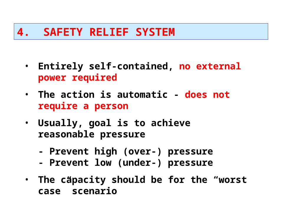
4. SAFETY RELIEF SYSTEM
• Entirely self-contained, no external power required
• The action is automatic - does not require a person
• Usually, goal is to achieve reasonable pressure
- Prevent high (over-) pressure- Prevent low (under-) pressure
• The capacity should be for the “worst case” scenario
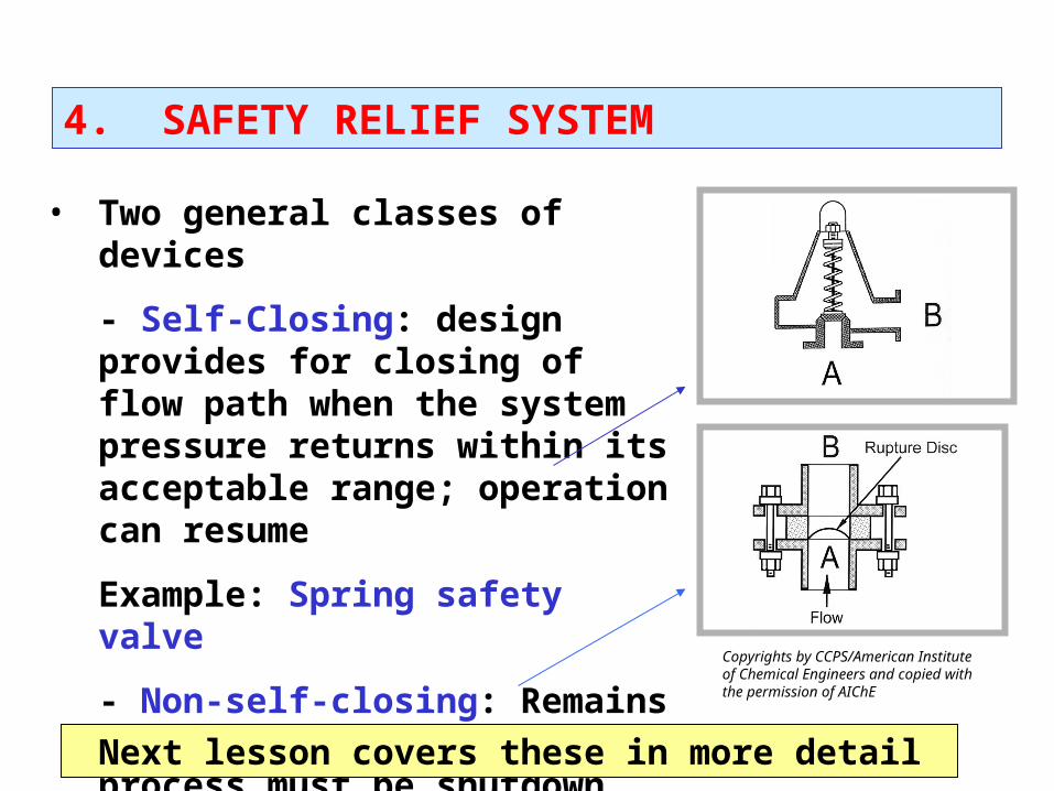
4. SAFETY RELIEF SYSTEM
• Two general classes of devices
- Self-Closing: design provides for closing of flow path when the system pressure returns within its acceptable range; operation can resume
Example: Spring safety valve
- Non-self-closing: Remains open. Typically, the process must be shutdown and the device replaced
Example: Burst diaphragm
Next lesson covers these in more detail
Copyrights by CCPS/American Institute of Chemical Engineers and copied with the permission of AIChE
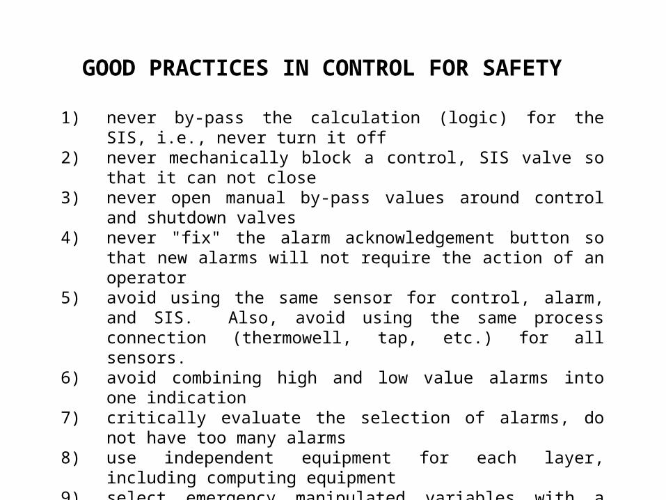
GOOD PRACTICES IN CONTROL FOR SAFETY
1) never by-pass the calculation (logic) for the SIS, i.e., never turn it off
2) never mechanically block a control, SIS valve so that it can not close
3) never open manual by-pass values around control and shutdown valves
4) never "fix" the alarm acknowledgement button so that new alarms will not require the action of an operator
5) avoid using the same sensor for control, alarm, and SIS. Also, avoid using the same process connection (thermowell, tap, etc.) for all sensors.
6) avoid combining high and low value alarms into one indication
7) critically evaluate the selection of alarms, do not have too many alarms
8) use independent equipment for each layer, including computing equipment
9) select emergency manipulated variables with a fast effect on the key process variable
10) use redundant equipment for critical functions11) provide capability for maintenance testing, since the
systems are normally in "stand-by” for long times - then must respond as designed!
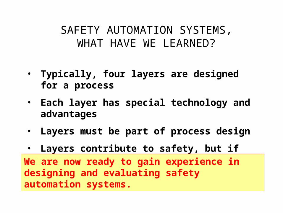
SAFETY AUTOMATION SYSTEMS,WHAT HAVE WE LEARNED?
• Typically, four layers are designed for a process
• Each layer has special technology and advantages
• Layers must be part of process design
• Layers contribute to safety, but if incorrect, can be unsafe
We are now ready to gain experience in designing and evaluating safety automation systems.
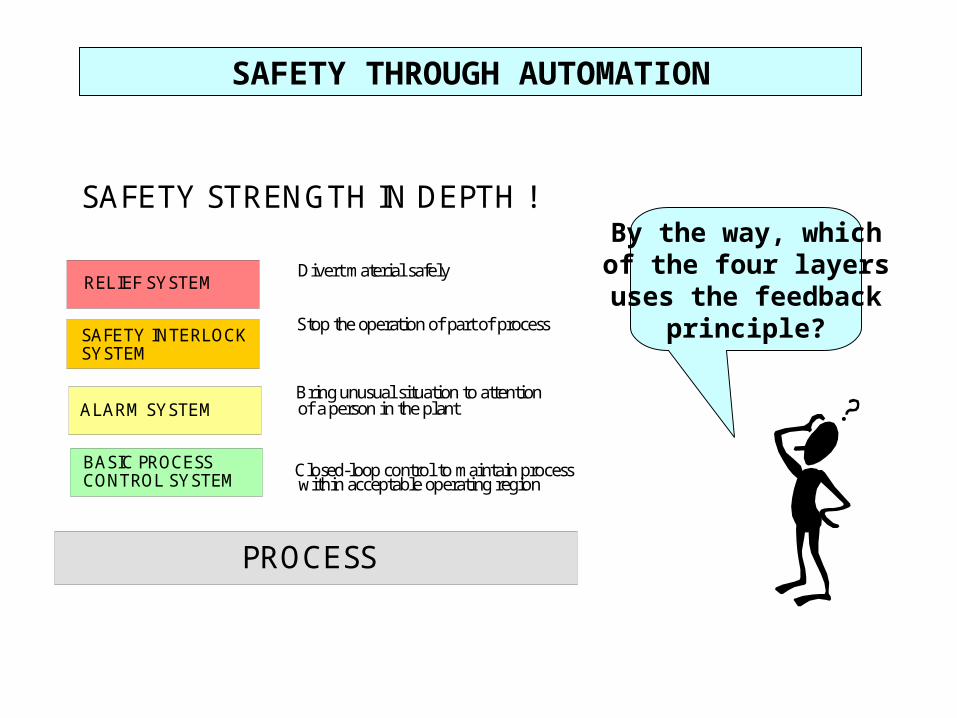
SAFETY STRENGTH IN DEPTH !
PROCESS
RELIEF SYSTEM
SAFETY INTERLOCK SYSTEM
ALARM SYSTEM
BASIC PROCESSCONTROL SYSTEM
Closed-loop control to maintain processwithin acceptable operating region
Bring unusual situation to attentionof a person in the plant
Stop the operation of part of process
Divert material safely
By the way, whichof the four layersuses the feedback
principle?
SAFETY THROUGH AUTOMATION
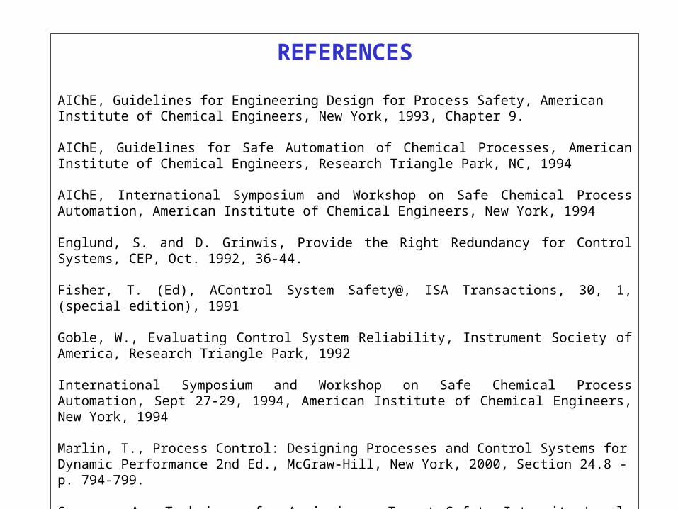
REFERENCES
AIChE, Guidelines for Engineering Design for Process Safety, American Institute of Chemical Engineers, New York, 1993, Chapter 9.
AIChE, Guidelines for Safe Automation of Chemical Processes, American Institute of Chemical Engineers, Research Triangle Park, NC, 1994
AIChE, International Symposium and Workshop on Safe Chemical Process Automation, American Institute of Chemical Engineers, New York, 1994
Englund, S. and D. Grinwis, Provide the Right Redundancy for Control Systems, CEP, Oct. 1992, 36-44.
Fisher, T. (Ed), AControl System Safety@, ISA Transactions, 30, 1, (special edition), 1991
Goble, W., Evaluating Control System Reliability, Instrument Society of America, Research Triangle Park, 1992
International Symposium and Workshop on Safe Chemical Process Automation, Sept 27-29, 1994, American Institute of Chemical Engineers, New York, 1994
Marlin, T., Process Control: Designing Processes and Control Systems for Dynamic Performance 2nd Ed., McGraw-Hill, New York, 2000, Section 24.8 - p. 794-799.
Summers, A., Techniques for Assigning a Target Safety Integrity Level, ISA Transactions, 37, 1998, 95-104.
SAFETY THROUGH AUTOMATION WORKSHOP 1
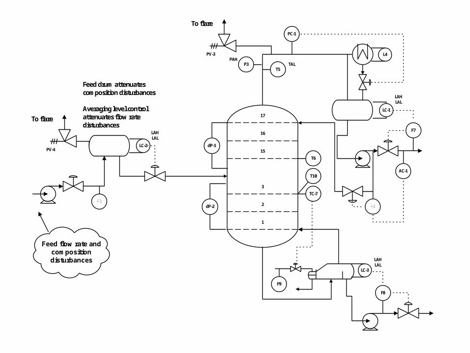
1. Review the distillation process on the next slide.
2. Locate at least one example of each of the four layers of safety automation
(If a layer is missing, add it.)
3. Evaluate each example that you find.
(Remember, the example is for educational purposes which could include errors for workshops.)
1
2
3
15
16
17
LC-1
LC-3
LC-2
Feed drum attenuates composition disturbances
Averaging level control attenuates flow rate disturbances
dP-1
dP-2
To flare
T5
T6
TC-7
AC-1
LAHLAL
LAHLAL
PAH
PC-1
P3
F3F4
F7
F8
F9
Feed flow rate and composition disturbances
PV-3
TAL
T10
L4
LAHLAL
To flare
PV-4
SAFETY THROUGH AUTOMATION WORKSHOP 2
1. Review the fired heater process on the next slide.
2. Equipment would be damaged and personnel could be injured if the combustion continued when the process is not operating properly.
Determine a mal-operation that could lead to unsafe operation.
3. Determine the sensors, the final element(s) and SIS logic to provide a safe system.
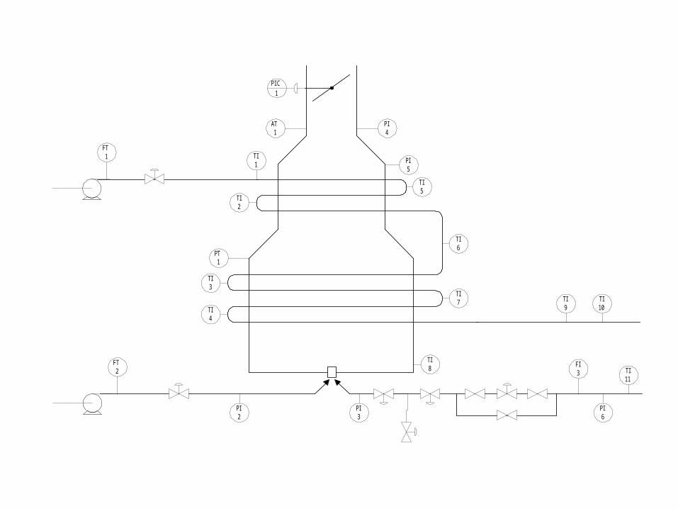
FT1
FT2
PT1
PIC
1
AT1
TI1
TI2
TI3
TI4
PI2
PI3
PI4
TI5
TI6
TI7
TI8
TI9
FI3
TI10
TI11
PI5
PI6