Embed Size (px)
Citation preview

Process Design and Heat Integration for the Power-to-Methanol Route
Léonard Grégoire, Giulini Davide, Villarreal-Singer Diego, Dumont Marie-Noëlle
Nice, ECCE 10, September 2015
1

Outline
1. Introduction
2. Model Description
3. Results
4. Heat Integration
5. Conclusions and Further Work
2

1. Introduction
3
Background: Renewable Energy Storage with Liquid Fuels
European Commission goals to reduce greenhouse gas emissions by 80%
below 1990 levels by 2050, 20% by 2020 (Energy Roadmap 2050).
Varying nature of renewable sources causes time imbalance between
production and consumption.
Need for energy storage at different time-scales:
Second and minute scale for frequency regulation
Inter-seasonal scale: Power-to-gas, power-to-fuel

1. Introduction
Power-to-Methanol route
I. CO2 Capture
II. H2O/CO2 Co-Electrolysis
III. Methanol Synthesis and Purification
Methanol as liquid energy carrier - easy and cheap long term energy storage
(22.7 MJ/kg) - converted to electricity or fuel use
- CO2 neutral, if renewable sources are used
Léonard et al., 2015. Electricity storage with liquid fuels in a zone powered by 100% variable renewables, IEEE 978-1-4673-6692-2. 4

2. Model Description
5
H2O/CO2 Co-Electrolysis model
1. H2 + CO2 → H2O + CO
2. H2O → H2 + ½ O2
CO2 → CO + ½ O2
3. H2 + CO2 → H2O + CO
- Redlich-Kwong-Soave equation of state
- Solid Oxide Electrolysis Cell at 850°C
and 1.013 bar
- H2O/CO2/H2 feed ratio: 100/45/10
- Operation at thermoneutral point
- H2O and CO2 utilization factor: 70%
Outlet
Gas Present Model Sun et al. (2012) Relative
Molar Fraction [%] Molar Fraction [%] Error [%]
H2O 15.2 15.0 1.33
H2 39.7 40.0 0.75
CO 33.2 32.0 3.75
CO2 11.7 12.0 2.50

2. Model Description
6
Methanol Synthesis model
CO2 + 3 H2 ↔ CH3OH + H2O
CO2 + H2 ↔ CO + H2O
Bos and Brilman, 2014. DOI:10.1016/j.cej.2014.10.059
Methanol Synthesis usually reaches
low per-pass conversions:
- Strongly exothermic reaction
(low temperature required)
- Need for high pressure (~50 bar)
- High recycle flow for industrial processes
Internal Condensation Reactor
- Internal liquid condensation and gas
recirculation
- Leads to 100% conversion
- Small scale applications allow better
heat management

2. Model Description
7
Methanol Synthesis model
DISTCOL
METRECOV
DISTCOND
PRGSPLIT
HTXREC
FLASH
COOLREACFEEDHEATMIX
REACTOR
BACKPRES
REACIN
REACOUT
DIST IN
DIST1
WAT
DIST2
EXHAUST
MET
R2REC
PURGE
R1
FLASHINFP5
S1
METWAT
1. Methanol Synthesis
- Redlich-Kwong-Soave equation of state
- Simplified Reactor (equilibrium is achieved): 250°C; 50 bar
- Side reactions neglected
- Condenser: 25°C; 50 bar
- Recycle (2% purge)
2. Methanol Purification
- NRTL model
- Distillation column
with 11 stages
- 1.013 bar

2. Model Description
8
Global Model
REQUIL
1RWGS
HT2
HT1
MIXER
SEP
RSTOIC
2ELECTR
REQUIL
3RWGS
DISTCOL
METRECOV
DISTCOND
PRGSPLIT
HTXREC
FLASH
COOLREAC
FEEDHEAT
FCOMP1
MIX
FCOMP2
ICFCONDKOD
ICFHTX
FEEDCOOL
REACTOR
HTXH2
BACKPRES
1IN
2IN
LIQ1
F3
CO2 F2
H2O
H2
2OUT
O2OUTCATHOUT
HOTSYNG
LIQ3
REACIN
REACOUT
DIST IN
DIST1
WAT
DIST2
EXHAUST
MET
R2REC
PURGE
R1
FLASHIN
FP5
MF3
FP1FP4
FP3
FP2
WATIC
MF2
WATKOD
S1
F1
METWAT
Sub-processes linked through 2 stages-compression with intermediate cooling.
Models of the two parts are validated separately, according to experimental
data available.
3. Results
9
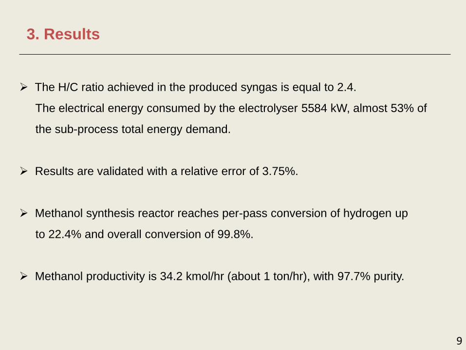
The H/C ratio achieved in the produced syngas is equal to 2.4.
The electrical energy consumed by the electrolyser 5584 kW, almost 53% of
the sub-process total energy demand.
Results are validated with a relative error of 3.75%.
Methanol synthesis reactor reaches per-pass conversion of hydrogen up
to 22.4% and overall conversion of 99.8%.
Methanol productivity is 34.2 kmol/hr (about 1 ton/hr), with 97.7% purity.

4. Heat Integration
Pinch Point Analysis
• Problem targeting:
6 cold streams – 7 hot streams
• Minimum approach ΔT: 20°C
• Pinch point: 245.2°C
• Minimum utility requirements
Hot: 935.6 kW
Cold: 1563.3 kW
Heat Exchanger Network
• Maximum energy recovery
design saves 73% of
energy required.
• Above the pinch:
3 HE and 5 hot utilities
• Below the pinch:
9 HE and 6 cold utilities
0100200300400500600700800900
0 500 1000 1500 2000 2500 3000 3500 4000 4500 5000 5500 6000
Shif
ted
Te
mp
era
ture
[°C
]
Heat Flow [kW]
Cold Composite Curve
Hot Composite Curve
0
1
2
3
4
5
6
7
8
9
10
11
12
13
0 50 100 150 200 250 300 350 400 450 500 550 600 650 700 750 800 850 900
He
at S
tre
am N
um
be
r
Actual Temperatures [°C]
Cold Hot Pinch Pinch
10

4. Heat Integration
Economic Evaluation
• Overall Heat Transfer Coefficient (U) preliminary
estimation for each exchanger.
• Total Heat Transfer Area (A) estimation: 2657 m2.
• Bare module cost (CBM) estimation using method
described by Turton et al. (2013), updated with
CEPC Index (April 2015): 6,292,835 €.
Q = U · A · ΔTLMTD · f
Atot = Σi[Qi / (ΔTLMTD,i · Ui)]
CBM = C0 · (B1 + B2 fm fp)
Efficiency Assessment
• Process efficiency without HEN: 51.4%.
• Process efficiency with HEN: 70.8%.
11
HHVout_Met – HHVin_H2
η = Qin + Pel + Pcomp
Inlet H2
HHV
(HHVin_H2)
Outlet Methanol
HHV
(HHVout_Met)
Electrical
Power Input
(Pel)
0.795 7.053 7.316
Hot Utilities
without HEN
(Qin)
Hot Utilities
with HEN
(Qin)
Compression
Power Input
(Pcomp)
4.265 0.936 0.590 MW

5. Conclusions and Further Work
12
An efficient process for CO2-neutral methanol production is proposed as
long-term energy storage.
Production rate of 1 tonCH3OH/hr, corresponding to typical decentralized
energy storage.
Benefits from a heat exchangers network design, but high capital cost
needed.
Solid Oxide cells allow both electrolysis and fuel cell mode.
A preliminary model is proposed, some further improvements are required:
- Use of recycled H2 for the electrolyser
- Pressurized electrolyser
- Build a detailed reactor to implement methanol synthesis kinetics
Integration of carbon capture (Léonard, 2014) in the efficiency assessment.

Nice, ECCE 10, September 2015
Thank you for your attention!
13