Embed Size (px)
Citation preview
14. Symposium Energieinnovation, 10.-12.02.2016, Graz/Austria
Seite 1 von 24
ENERGY SAVINGS OF INTERCOMPANY HEAT
INTEGRATION - A METHODOLOGICAL
FRAMEWORK – PART I
Ali Aydemir, Clemens Rohde, Simon Möhren
Fraunhofer Institute for Systems and Innovation Research ISI, Breslauer Strasse 48, 76139 Karlsruhe, Germany, +49 721 6809 305, [email protected],
www.isi.fraunhofer.de
Abstract:
Background and literature review
Heat or process integration is a technical concept to minimize the cooling and heating
requirements of industrial plants. The basic idea behind heat integration is to interconnect
processes requiring cold with those requiring heat via a heat exchanger, thus reducing the
overall energy demand (Kemp, 2007). The more processes that can be interconnected within
a heat exchanger network (HEN), the more savings heat integration can achieve. Thus, it is
recommended that production sites featuring more than one factory/production hall set up
HENs which extend beyond the individual production halls. An additional concept is to
interconnect production sites not belonging to the same company. This concept is called
intercompany process or heat integration (Hiete et al., 2012).
Several case studies exist that analyse large production sites or industrial estates and
assess the potential energy savings due to HENs. The studies focus mainly on the
methodologies of how to analyse total sites. Only a few publications are explicitly dedicated
to the field of “intercompany energy integration” and discuss the relevant factors.
The potential energy savings due to intercompany heat integration have not been estimated
so far for Germany. This is mainly due to the lack of data. However, it would be useful to
have a structured method for estimating the energy saving potentials due to intercompany
heat integration beyond case study approaches, especially with regard to policy design to
increase the uptake of heat integration and industrial energy demand projections. This paper
presents part of a methodological framework to systematically estimate these potentials for
regions, which combines methodologies from spatial analysis and heat integration. The focus
in this paper is on the methodologies from heat integration and paves the way for another
paper dealing with the methodologies from spatial analysis.
Methodology to assess HENs and its practical application
To quantify the energy-saving potentials of intercompany heat integration, it is necessary to
have information on the heating and cooling requirements of the affected companies and
their respective location. Furthermore, a methodology is needed to assess a possible HEN
based on this information. In this paper, we present and apply a methodology for assessing
intercompany HENs, a step which represents one major pillar of the overall methodological
framework.
First, we describe the methodology applied. Special attention is paid to aspects relevant for
intercompany heat integration such as investments in pipes and possible part-load operation.
14. Symposium Energieinnovation, 10.-12.02.2016, Graz/Austria
Seite 2 von 24
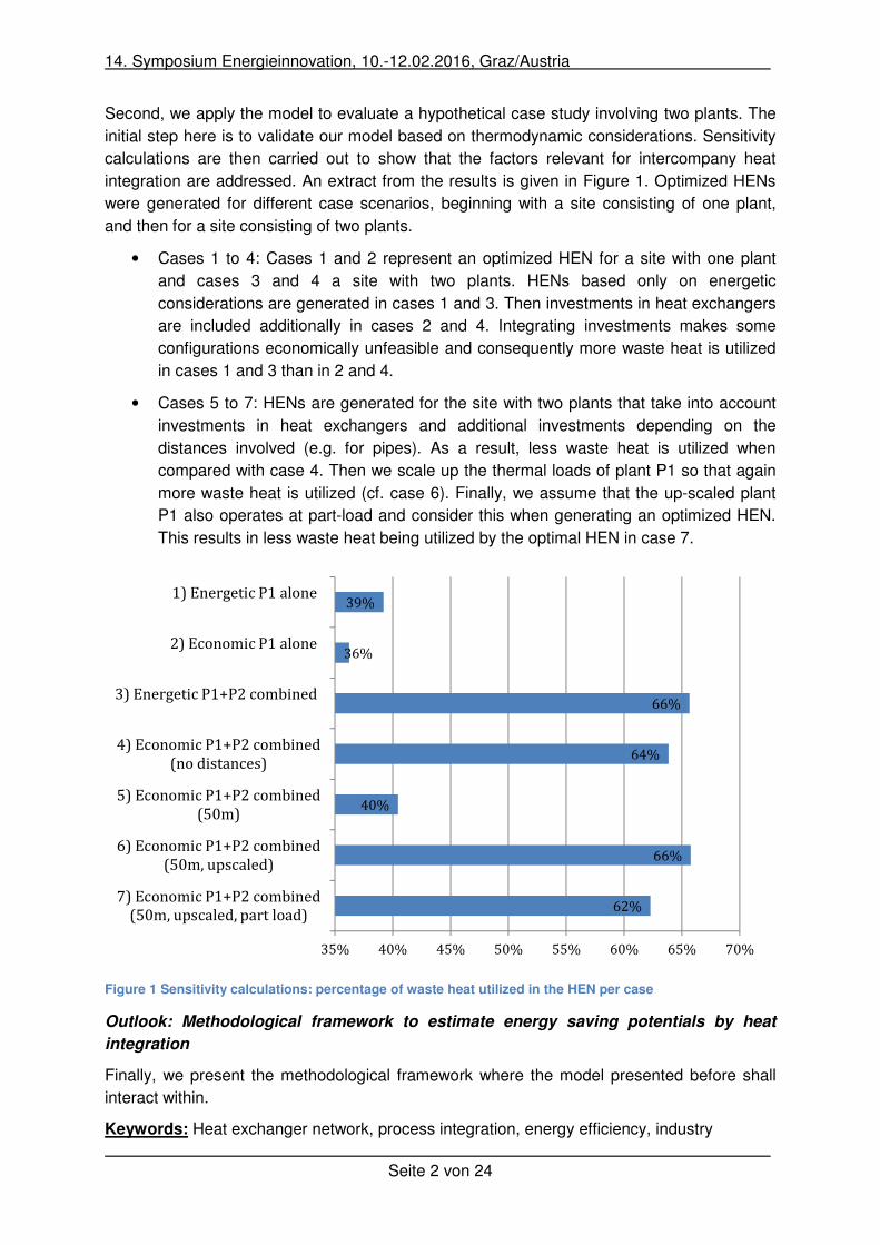
Second, we apply the model to evaluate a hypothetical case study involving two plants. The
initial step here is to validate our model based on thermodynamic considerations. Sensitivity
calculations are then carried out to show that the factors relevant for intercompany heat
integration are addressed. An extract from the results is given in Figure 1. Optimized HENs
were generated for different case scenarios, beginning with a site consisting of one plant,
and then for a site consisting of two plants.
• Cases 1 to 4: Cases 1 and 2 represent an optimized HEN for a site with one plant
and cases 3 and 4 a site with two plants. HENs based only on energetic
considerations are generated in cases 1 and 3. Then investments in heat exchangers
are included additionally in cases 2 and 4. Integrating investments makes some
configurations economically unfeasible and consequently more waste heat is utilized
in cases 1 and 3 than in 2 and 4.
• Cases 5 to 7: HENs are generated for the site with two plants that take into account
investments in heat exchangers and additional investments depending on the
distances involved (e.g. for pipes). As a result, less waste heat is utilized when
compared with case 4. Then we scale up the thermal loads of plant P1 so that again
more waste heat is utilized (cf. case 6). Finally, we assume that the up-scaled plant
P1 also operates at part-load and consider this when generating an optimized HEN.
This results in less waste heat being utilized by the optimal HEN in case 7.
Figure 1 Sensitivity calculations: percentage of waste heat utilized in the HEN per case
Outlook: Methodological framework to estimate energy saving potentials by heat
integration
Finally, we present the methodological framework where the model presented before shall
interact within.
Keywords: Heat exchanger network, process integration, energy efficiency, industry
62%
66%
40%
64%
66%
36%
39%
35% 40% 45% 50% 55% 60% 65% 70%
7) Economic P1+P2 combined
(50m, upscaled, part load)
6) Economic P1+P2 combined
(50m, upscaled)
5) Economic P1+P2 combined
(50m)
4) Economic P1+P2 combined
(no distances)
3) Energetic P1+P2 combined
2) Economic P1 alone
1) Energetic P1 alone
14. Symposium Energieinnovation, 10.-12.02.2016, Graz/Austria
Seite 3 von 24
1 Background
Increasing energy efficiency in every sector is a major pillar of Germany’s energy policy to
tackle climate change and increase supply security. Intercompany heat integration is one
option to increase energy efficiency in industry. This refers to integrating the heat supply of
companies in close spatial proximity to each other. So far, the potential energy savings due
to intercompany heat integration have not yet been estimated for Germany. This is mainly
due to the lack of data. Thus, it would be useful to have a structured way to estimate the
energy-saving potentials due to intercompany heat integration beyond case study
approaches, especially with regard to designing policy to increase the uptake of heat
integration.
Energy demand models are employed to estimate the possible energy savings due to energy
efficiency measures under differing policy scenarios. Currently, they do not address the
efficiency option of intercompany heat integration but could be extended by a framework to
assess its energy saving potential. Potential energy savings due to intercompany heat
integration could then be included in industrial energy demand projections as well.
This paper presents a methodological framework to systematically estimate these potentials
for regions, which combines methodologies from spatial analysis and heat integration. The
focus in this paper is on the methodologies from heat integration and it paves the way for
another paper dealing with the methodologies from spatial analysis.
1.1 Waste heat in the context of policy goals
In Germany, industry accounts for approximately 30% of final energy demand (Rohde, 2013).
75% of this share is used to provide heat, of which 65% is process heat. Thus options to
improve the energy efficiency of heat generation in industry are of major relevance for energy
policy in Germany.
Waste heat is generated by many industrial processes using process heat. From a technical
point of view, waste heat can be described as unwanted heat generated by an industrial
process (Pehnt, 2010). From a social point of view, it can be described as heat which is a by-
product of industrial processes and currently not utilized, but which could be used for society
and industry in the future (Viklund et al., 2014). Pehnt et al. (2011) estimate the waste heat
over 140°C for different economic sectors in Germany. With regard to the final energy
necessary to generate the appropriate process heat, they estimate waste heat potentials for
Germany of between 3% and 40% depending on the sector. The total estimated amount of
available waste heat over 140°C corresponds to 12% of industrial final energy consumption.
In order to harvest these energy-saving potentials in Germany, the utilization of waste heat is
supported by a dedicated funding scheme and accompanying measures are considered
within the National Action Plan for Energy Efficiency (BMWi, 2014).
Several measures have to be considered when evaluating the energy-saving potentials of
utilizing waste heat (SAENA, 2012). First, measures to eliminate waste heat should be
evaluated. If this is not possible, it can be evaluated whether heat recovery measures are
energetically and economically feasible.
14. Symposium Energieinnovation, 10.-12.02.2016, Graz/Austria
Seite 4 von 24
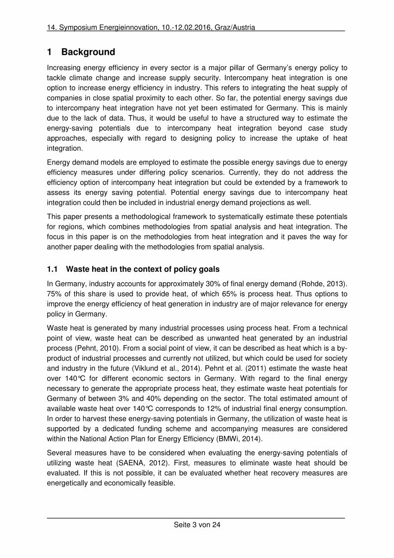
Heat recovery measures can be applied within or outside the processes generating the
waste heat. One example for heat recovery within the process is the use of an economizer in
a steam generation system to recover energy from the exhaust gas for pre-heating the
feedwater. An example for heat recovery outside the process is using the waste heat from an
industrial furnace to heat an office building. Heat recovery applied outside the process can
be further differentiated according to whether the measure takes place only inside the
company producing the waste heat or also outside the company. An overview of the
differentiation of heat recovery measures is given in Figure 2. Finally, waste heat can be
recovered and also used to generate other process media such as electricity or cold.
Intercompany heat integration is a heat recovery measure which takes place across
company boundaries. In the following, the basic terms of intercompany heat integration are
introduced and the state of knowledge is presented.
Figure 2: Heat recovery within a process (left-hand side); heat recovery outside a process with possible company border (right-hand side) (adapted from Hirzel et al., 2013)
1.2 Heat integration: a technical concept to reduce energy demand
Heat or process integration is a technical concept to minimize the cooling and heating
requirements of industrial plants. The basic idea behind heat integration is to interconnect
processes requiring cold with processes requiring heat via a heat exchanger, thus reducing
the overall energy demand (Kemp, 2006). A system of heat exchangers interconnecting
several processes requiring heat and cold is called a heat exchanger network (HEN). Such
HENs are common in the chemical industry (Smith, 2005). The more processes that can be
interconnected at reasonable expense within a HEN, the more savings can be achieved with
heat integration. Thus, production sites with more than one factory/production hall could set
up HENs that extend beyond production halls. An additional concept is to interconnect
production sites not belonging to the same company. This concept is called intercompany
process or heat integration (Hiete et al., 2012). Here, two or more companies use the same
HEN with the aim of reducing their overall energy demand with respect to heating and
cooling.
Pro
cess
Useful energy
Heat
recovery
Non usable
waste heat
Recovered
heat
Pro
cess 1
Useful energy 1
Heat
recovery
Useful energy 2
Pro
cess 2Non usable
waste heat
Non usable
waste heat
Possible company
border
14. Symposium Energieinnovation, 10.-12.02.2016, Graz/Austria
Seite 5 von 24
The scientific literature addresses intercompany heat integration directly and indirectly. There
are several case studies analysing large production sites or industrial estates to assess
potential energy savings. The papers focus mainly on the methodologies for analysing sites
and address intercompany heat integration indirectly. For example, Hackl et al. (2011) apply
total site analysis (TSA) to an industrial estate consisting of five chemical companies. They
show that the current utility demand could be eliminated completely by using a HEN.
Further papers and studies estimate the heat recovery potentials for specified regions. These
studies and/or papers deal with how to identify and quantify the amount of waste heat
available in regions and how to estimate the technological and economical potentials to
recover these amounts of heat. Among the technological options considered, intercompany
heat integration might be addressed indirectly as well. For example, in a report prepared by
element energy (2014), the potential for recovering and using waste heat from industry is
estimated for the UK. To do so heat loads, related waste heat and nearby heat sinks around
the waste heat sources are modelled spatially. The recovery potential is then calculated by
applying a techno-economic model. Within this model, competing technological options are
evaluated for each source of waste heat and the best one is selected with regard to technical
or economical objectives. “Over-the-fence” solutions connecting the modelled waste heat
sources and nearby sinks are also taken into account. Nearby heat sinks might be district
heating networks or other companies. Thus, intercompany heat integration is included as a
technological option in this study. However, the modelling assumes only a single source sink-
technology combination, i.e. point-to-point and not an integrated heat network. Thus the
potential saving due to intercompany heat integration might be underestimated, especially for
industrial estates.
District heating networks are also usually operated by companies. With this in mind, a
connection between a plant and a district heating network could be considered a case of
intercompany heat integration as well. Thus, papers dealing with the use of industrial waste
heat in district heating networks might address intercompany heat integration in a wider
sense as well. Examples can be found in Broberg et al. (2012), and Hummel et al. (2014).
Finally, a few publications are explicitly dedicated to the field of “intercompany energy
integration”. For instance, Hiete et al. (2012) examine a hypothetical case study where a set
of companies is located around a chemical pulp manufacturer. They assess a HEN
interconnecting these sites including investments in pipes and heat exchangers.
Furthermore, they model the decision process whether and how a HEN could be established
between the participating companies using game theory. Please note that ‘intercompany
energy integration’ is the umbrella term for ‘intercompany heat integration’ and also covers
the aspect of two or more companies sharing utilities as well as HENs across company
boundaries (Fichtner et al., 2002). Hills et al. (2014) also deal explicitly with intercompany
heat integration. They analyse the suitability of different industries for inter-site heat
integration. First, they model heat loads for a steel, cement, paper and fertiliser plant. Then,
they demonstrate the theoretical savings which could be achieved by interconnecting theses
sites using a HEN. The HEN is modelled by applying Pinch analysis and evaluated
technically and economically. However, due to the limitations of Pinch analysis, investments
for pipes are not taken into account.
14. Symposium Energieinnovation, 10.-12.02.2016, Graz/Austria
Seite 6 von 24
2 Methodological framework
In order to quantify the energy-saving potentials of intercompany heat integration, it is
necessary to have information on the heating and cooling requirements of the affected
companies and their respective location. Furthermore, a methodology is needed to assess a
possible HEN based on this information. In this paper, we present and apply a methodology
for assessing intercompany HENs, which represents one major pillar of the overall
methodological framework.
In the following, we first present different approaches to generate HENs. We discuss Pinch
analysis as the most common approach to generate energetically-optimized HENs. We then
look at mathematical approaches to generate energetically-optimized HENs. Based on this,
we present arguments why mathematical approaches are best suited to the central question
here; estimating the energy saving-potentials of intercompany heat integration.
Second, we describe the methodology applied in our framework, which combines
approaches from Pinch analysis and operations research. Special attention is paid to aspects
relevant for intercompany heat integration such as investments in pipes, and heat losses. We
also describe how to address time-dependent load variations of the affected companies to a
certain extent.
2.1 Approaches to generate energetically-optimized HENs
For two processes interconnected by one heat exchanger, the amount of heat which can be
exchanged theoretically can be estimated quite simply, given the boundaries set by
temperatures, type and mass flow of the affected process media. If more than two processes
are being operated, it is still generally possible to interconnect each of them with more than
one of the other processes using a HEN. However, it is more difficult to calculate the amount
of heat which can be exchanged theoretically as the boundaries set by each process are less
clear (Raskovic, 2009). This is also the problem when designing a feasible HEN, mainly due
to the high number of possible networks which have to be evaluated. For five hot and five
cold processes, the number of possible (not valid) network combinations is 25! ≈ 1.5 ∙ 10. 2.1.1 Pinch analysis
Different techniques and approaches to design feasible HEN configurations exist. Among
them, Pinch analysis-based approaches are the most common in industry (Natural
Resources Canada, 2003). They provide a framework to generate feasible HENs with the
aim of reducing the overall energy demand based on thermodynamic considerations
(Radgen, 1996). The basics of Pinch analysis were introduced by Linnhoff et al. (1978). They
presented design rules on how to generate feasible HENs with minimum energy
requirements. The methodology was then further developed to account for the trade-off
between capital costs and energy recovery (Linnhoff and Ahmad, 1990). The final Pinch
design method was presented in Linnhoff and Ahmad (1990), and Ahmad et al. (1990). One
way to categorize the approaches used to design HENs is to distinguish between Pinch
analysis-based approaches and approaches using mathematical programming, i.e.
mathematical approaches (Koraviyotin and Siemanond (2015)).
14. Symposium Energieinnovation, 10.-12.02.2016, Graz/Austria
Seite 7 von 24
The basic idea of Pinch analysis is to identify the so called ‘pinch’, which separates the
overall system into two thermodynamically distinct regions, resulting in two separate design
problems. The processes are divided up into those that have to be heated up and those that
have to be cooled down and separated according to temperature intervals. The temperature
intervals used to separate the flows are generated based on the inlet and outlet temperature
of each process flow and the minimum temperature difference chosen for the heat
exchanger. These intervals finally serve to identify the heating and cooling demand for the
overall system. This is done by calculating the energy requirements of each process within
each temperature interval using the heat capacity and mass flow of the affected processes
under the assumption that heat capacities are independent of temperature. The calculated
amounts are then usually summed up and visualised in diagrams that plot the so called hot
and cold composite curves. The pinch is the temperature where the hot and cold composite
curves are closest to each other considering a minimum temperature driving force. The
minimum heating and cooling requirements can then be estimated directly based on the
diagram.
To design a HEN with minimum energy requirements, the corresponding network is then
formed by applying design heuristics considering the so called pinch rules. The design is
separated by the pinch, resulting in a design problem above and below the pinch. The pinch
rules then prescribe that the HEN is designed for both problems such that no cold utilities are
used above the pinch, no hot utilities below the pinch, and that no heat is transferred across
the pinch. The central design heuristic suggests creating networks for both problems by
starting at the pinch, where the problem is most constrained.
Software exists to create HENs based on Pinch analysis. This supports engineers in creating
feasible HENs considering the pinch rules (i.e. PinCH, www.pinch-analyse.ch). It provides
the user with suggestions on how to develop the HEN. As the designer still controls the
procedure, such approaches can be classified as semi-automatic. However, semi-automatic
Pinch analysis-based approaches do not guarantee the optimal solution, i.e. the HEN with
minimum energy requirements (Stanislaw Sieniutycz and Jacek Jezowski, 2013).
Furthermore, a HEN that achieves minimum energy targets by separating the problem into a
design above and below the pinch usually needs more heat exchangers, than if the pinch
division had been ignored (Kemp, 2006). Thus, options ignoring pinch rules might offer
advantages in some design cases (Radgen, 1996). Finally, large problems could lead to
combinatorial challenges for the designer.
2.1.2 Mathematical approaches
Mathematical approaches generate feasible HENs automatically. Objective functions are
formulated to generate a HEN with minimum energy requirements. Cerda et al. (1983)
presented the first mathematical approach to generate feasible HENs using the transport
algorithm. Other approaches exist, such as models using transhipment algorithms (Papoulias
and Grossmann (1983), Chen et al. (2015)) and superstructure models to retrofit HENs and
for HEN synthesis (Ciric and Floudas (1989), Yee and Grossmann (1990)). An overview of
the mathematical approaches to generate HENs is given in Escobar and Trierweiler (2013).
14. Symposium Energieinnovation, 10.-12.02.2016, Graz/Austria
Seite 8 von 24
The advantages of mathematical models are that they are systematic and can be
implemented automatically. Furthermore, they can be extended flexibly by adjusting objective
functions and/or adding constraints so that, for example, the number of heat exchangers can
be minimized. Finally, generating HENs using linear formulated mathematical models is
much faster than using Pinch analysis-based approaches.
2.1.3 Conclusion based on requirements
Our goal is to develop a model framework for estimating the energy-saving potentials of
intercompany heat integration in regions to be specified. With regard to intercompany HENs,
the distances between participating companies are of major relevance as investments in
piping can crucially influence the cost efficiency of intercompany HENs (Ludwig, 2012). Pinch
analysis-based approaches currently do not provide the possibility to address investments for
piping by taking distances into account, which is one of their major drawbacks. Furthermore,
we want to provide a framework which allows flexible adaptation of the size of the region
depending on policy research needs. This means the framework must be able to assess
industrial estates, cities, metropolitan areas and much larger regions using the same
approach. For example, for metropolitan areas, it is typically necessary to evaluate
intercompany HENs for several hundred companies. This would be very time consuming
using Pinch analysis-based approaches and is another drawback in terms of our goal.
Therefore, we argue that mathematical approaches are best suited to evaluating
intercompany HENs. We use a transport algorithm in our framework. As a linear model is
formulated, it can be guaranteed that intercompany HENs are evaluated and compared
rapidly and reliably. The structure of the model also allows several topics relevant for
intercompany HENs to be addressed, such as investments in piping and the dynamic loads
of the assessed companies. In the following, we describe how we address such factors in our
model to assess intercompany HENs.
2.2 Generating intercompany HENs using the transport algorithm
Cerda et al. (1983) demonstrate how to generate energetically-optimized HENs by combining
approaches from Pinch analysis and operations research. In Pinch analysis, each hot and
cold process flow is separated according to temperature intervals to calculate the energy
requirements for each process in each interval. This approach is used in classical Pinch
analysis to create composite curves to identify the pinch and generate an energetically-
optimized HEN based on heuristic rules (Stanislaw Sieniutycz and Jacek Jezowski, 2013).
However, this separation also allows each cold process flow to be represented by a set of
energy demands and each hot process flow by a set of energy supplies. This is why the task
of generating an energetically-optimized HEN can be formulated as a general transport
problem.
The transport problem has its origins in operations research and deals with the task of
minimizing the transport costs between supplies and demands, given the cost for each
possible route between supply and demand (Fourer et al., 2003). The objective function of
the general minimization equation for transport problems is as follows: �� ��� ∑ ∑ ��� ∙ ����� .
The costs per unit transported from supply i to demand j are indicated by ���, and ��� represents the quantity transported from the same supply to the same demand.
14. Symposium Energieinnovation, 10.-12.02.2016, Graz/Austria
Seite 9 von 24
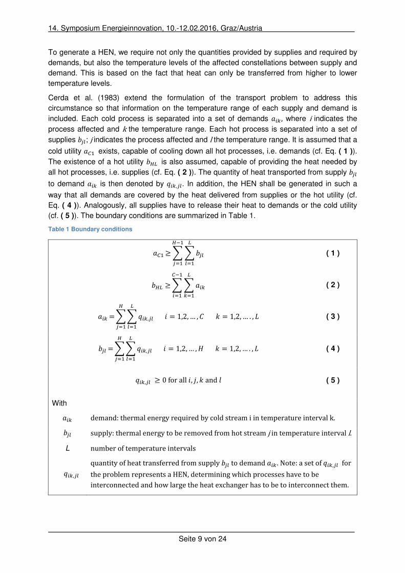
To generate a HEN, we require not only the quantities provided by supplies and required by
demands, but also the temperature levels of the affected constellations between supply and
demand. This is based on the fact that heat can only be transferred from higher to lower
temperature levels.
Cerda et al. (1983) extend the formulation of the transport problem to address this
circumstance so that information on the temperature range of each supply and demand is
included. Each cold process is separated into a set of demands ��� , where i indicates the
process affected and k the temperature range. Each hot process is separated into a set of
supplies ���; jindicates the process affected and l the temperature range. It is assumed that a
cold utility � ! exists, capable of cooling down all hot processes, i.e. demands (cf. Eq. ( 1 )).
The existence of a hot utility �"# is also assumed, capable of providing the heat needed by
all hot processes, i.e. supplies (cf. Eq. ( 2 )). The quantity of heat transported from supply ��� to demand ��� is then denoted by $��,��. In addition, the HEN shall be generated in such a
way that all demands are covered by the heat delivered from supplies or the hot utility (cf.
Eq. ( 4 )). Analogously, all supplies have to release their heat to demands or the cold utility
(cf. ( 5 )). The boundary conditions are summarized in Table 1.
Table 1 Boundary conditions
� !≥&&���#�'!
"(!�'! ( 1 )
�"# ≥&&���#�'!
(!�'! ( 2 )
��� =&&$��,��#�'!
"�'! � = 1,2,… , +, = 1,2,… . , - ( 3 )
��� =&&$��,��#�'!
"�'! � = 1,2,… ,., = 1,2,… . , - ( 4 )
$��,�� ≥ 0forall�, 3, ,and6 ( 5 )
With ��� demand:thermalenergyrequiredbycoldstreamiintemperatureintervalk. ��� supply:thermalenergytoberemovedfromhotstreamjintemperatureintervall.L numberoftemperatureintervals $��,�� quantityofheattransferredfromsupply���todemand��� .Note:asetof$��,�� fortheproblemrepresentsaHEN,determiningwhichprocesseshavetobeinterconnectedandhowlargetheheatexchangerhastobetointerconnectthem.
14. Symposium Energieinnovation, 10.-12.02.2016, Graz/Austria
Seite 10 von 24
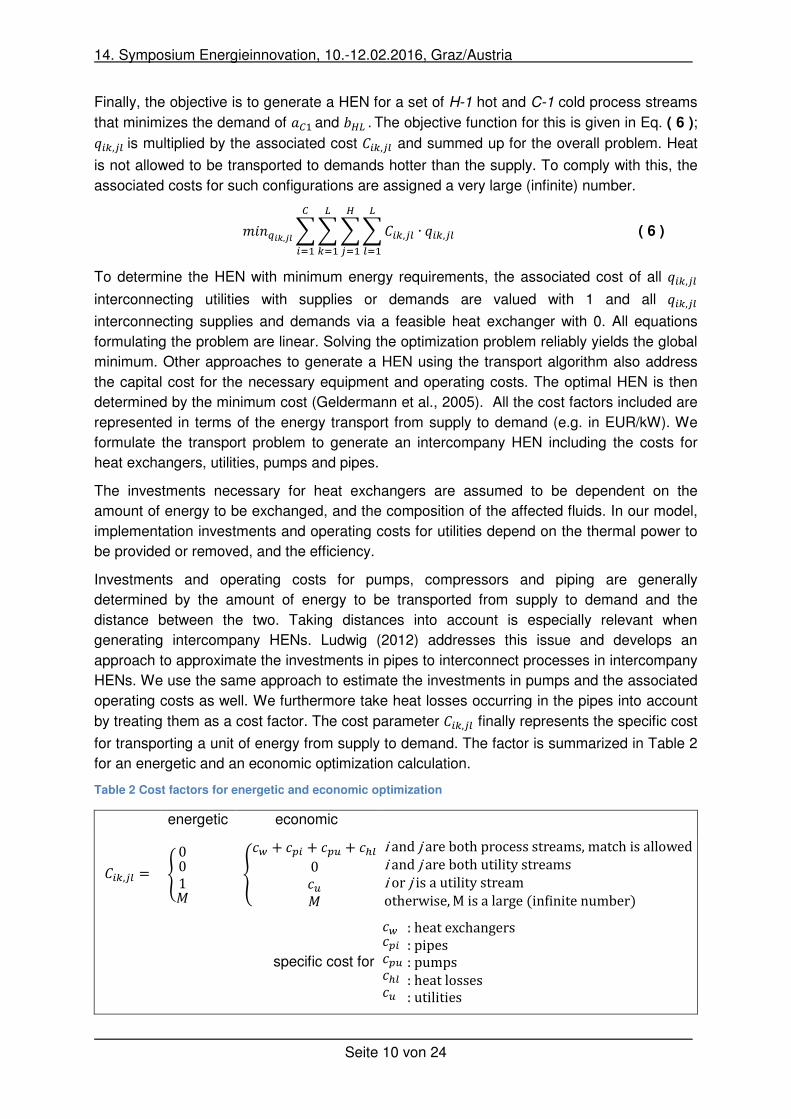
Finally, the objective is to generate a HEN for a set of H-1 hot and C-1 cold process streams
that minimizes the demand of � !and �"#.The objective function for this is given in Eq. ( 6 ); $��,�� is multiplied by the associated cost +��,�� and summed up for the overall problem. Heat
is not allowed to be transported to demands hotter than the supply. To comply with this, the
associated costs for such configurations are assigned a very large (infinite) number.
�� J�K,�L &&&&+��,�� ∙ $��,��#�'!
"�'!
#�'!
�'! ( 6 )
To determine the HEN with minimum energy requirements, the associated cost of all $��,�� interconnecting utilities with supplies or demands are valued with 1 and all $��,�� interconnecting supplies and demands via a feasible heat exchanger with 0. All equations
formulating the problem are linear. Solving the optimization problem reliably yields the global
minimum. Other approaches to generate a HEN using the transport algorithm also address
the capital cost for the necessary equipment and operating costs. The optimal HEN is then
determined by the minimum cost (Geldermann et al., 2005). All the cost factors included are
represented in terms of the energy transport from supply to demand (e.g. in EUR/kW). We
formulate the transport problem to generate an intercompany HEN including the costs for
heat exchangers, utilities, pumps and pipes.
The investments necessary for heat exchangers are assumed to be dependent on the
amount of energy to be exchanged, and the composition of the affected fluids. In our model,
implementation investments and operating costs for utilities depend on the thermal power to
be provided or removed, and the efficiency.
Investments and operating costs for pumps, compressors and piping are generally
determined by the amount of energy to be transported from supply to demand and the
distance between the two. Taking distances into account is especially relevant when
generating intercompany HENs. Ludwig (2012) addresses this issue and develops an
approach to approximate the investments in pipes to interconnect processes in intercompany
HENs. We use the same approach to estimate the investments in pumps and the associated
operating costs as well. We furthermore take heat losses occurring in the pipes into account
by treating them as a cost factor. The cost parameter +��,�� finally represents the specific cost
for transporting a unit of energy from supply to demand. The factor is summarized in Table 2
for an energetic and an economic optimization calculation.
Table 2 Cost factors for energetic and economic optimization
energetic economic
+��,�� = M001NO P�Q + �S� + �ST + �U�0�TN O iandjarebothprocessstreams,matchisallowediandjarebothutilitystreamsiorjisautilitystreamotherwise,Misalarge(inXinitenumber)
specific cost for
�Q �S��ST�U��T
:heatexchangers:pipes:pumps:heatlosses:utilities
14. Symposium Energieinnovation, 10.-12.02.2016, Graz/Austria
Seite 11 von 24
In order to assess intercompany HENs in a wider, systemic context, it might be relevant to
address the dynamic load profiles of the participating plants as well. Let us assume that a
plant provides “waste”-heat to another plant via a HEN. If this plant then starts to operate at
part-load and provides less heat to the interconnected plant than under the original design
conditions, then the interconnected plant has to make up the missing heat using its own
utilities. This circumstance could be addressed by simulating the behaviour of HENs derived
by optimization on an hourly basis and then optimizing the HEN again with regard to variable
load behaviour. This is a system dynamics approach, which is also possible due to the hourly
simulation of storages etc. However, this would increase the size of the problem and the
calculating time as well. We want to develop a model framework applicable to estimating the
energy-saving potentials in “larger” regions. This usually requires the assessment of HENs
for several hundreds of companies, making calculating time a significant factor. Therefore,
we have to compromise between technologically very detailed modelling (system dynamics
approach) and taking dynamic aspects into account by addressing dynamic load behaviour in
the formulation of the transport problem. For the estimation of energy-saving potentials due
to intercompany heat integration, the assumption is that companies include predicted load
variations in the assessments of a possible HEN between them. Such an approach has the
advantage that the problem is still linear, and the calculation time per constellation does not
increase in general. Therefore, we extend the formulation of the objective function as follows:
�� JZ�K,Z�L&&&&&+[��,[�� ∙ $[��,[��#�'!
"�'!
#�'!
�'!
\['! ( 7 )
The quantity of heat transported from supply �[�� to demand �[�� is then denoted by $[��,[��; t indicates the time in the formulation. As heat exchanger surfaces cannot be adjusted from
time step to time step, further boundary conditions are necessary to guarantee that the
network generated is technically feasible. First, we add a constraint to guarantee that no links
are generated between supplies and demands from different time steps (cf. Eq. ( 8 )). $[��,[�� ≥ 0forall�, 3, ,, 6� ]^, but $[��,[�� = 0if^fromsupplyanddemandisnotequal ( 8 )
Second, we add a constraint to guarantee that the heat exchanger can work at full capacity,
but not above. Therefore, we always model the first time step as a full load case for all
processes. We further assume that the thermal requirements of processes are linearly
dependent on the load in the plant. Thus, we introduce a part-load factor PF.PFrepresents a
lower load of the processes where the supplies and demands come from. For example, for a
hot and a cold process, one demand and one supply is generated for two time steps. The
supply operates at 50% part load in the second time step, but the demand stays at full load.
Thus, the heat which can be exchanged between the supply and demand in the second time
step is restricted with regard to the first time step as follows: $!!,!! ≤ $!!!,!!! ∙0.5.Accordingly, the constraint is given in Eq. ( 9 ).
$[��,[�� ≤ $!��,!�� ∙ bc[ , forall�, 3, ,, 6and^ , with bc[ ≤ 1 ( 9 )
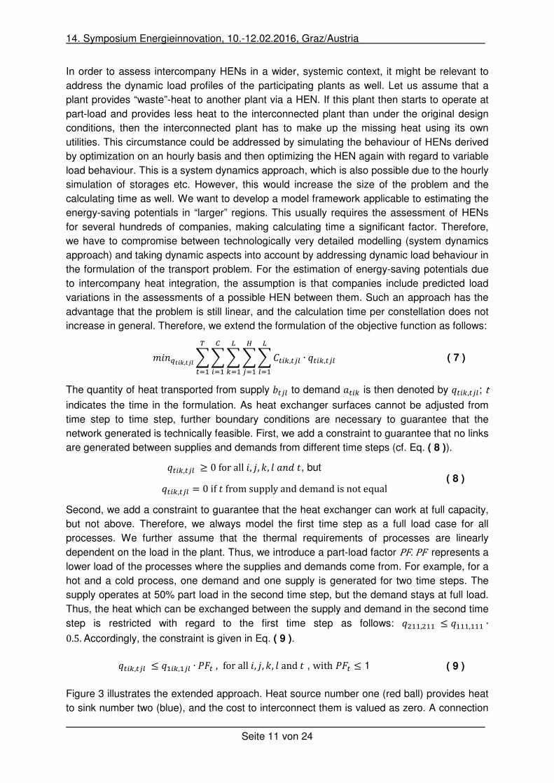
Figure 3 illustrates the extended approach. Heat source number one (red ball) provides heat
to sink number two (blue), and the cost to interconnect them is valued as zero. A connection
14. Symposium Energieinnovation, 10.-12.02.2016, Graz/Austria
Seite 12 von 24
from source number one to sink number three is not allowed so the interconnection costs are
valued as infinite. Interconnections from heat source number one in time step one to heat
sinks in time step two are generally valued with the same cost applied within one time step.
However, Eq. ( 8 ) stops connections being generated between different time steps.
Furthermore Eq. ( 9 ) compares the possible connection between heat source one and heat
sink two for different time steps and forces them to stand in a certain relation to each other .
Figure 3 Visualisation of the extended approach (blue: heat sinks, red: heat source)
3
210
3
210
Time step 2
Time step 1
Eq.8
Eq.9
14. Symposium Energieinnovation, 10.-12.02.2016, Graz/Austria
Seite 13 von 24
3 A case study of intercompany energy integration
We apply the model in a case study to evaluate the hypothetical interconnection of two plants
within a HEN. The goal of the case study is to provide:
• A validation of the energetic optimization calculation.
• A comparison of the economic optimization calculation with a consultant report.
• A sensitivity test with regard to the factors relevant for intercompany heat integration.
We chose a coating plant (P1) as the first plant for the system to be optimized. This
represents a plant which could potentially deliver heat to another plant. The chosen coating
plant has already been analysed by a team of consultants from the Swiss Energy Agency
with regard to its energetic optimization potentials (Grieder et al., 2011). They employed
Pinch analysis using the commercial software PinCH to assess thef potential energy savings
of using a HEN.
Two coating processes are applied within the plant. For component parts with high coating
requirements, a process is used with organic pulverized paint (EPS-coating). Other
component parts are coated with porcelain enamel (Enamel-coating). The components are
pre-treated prior to each coating process.
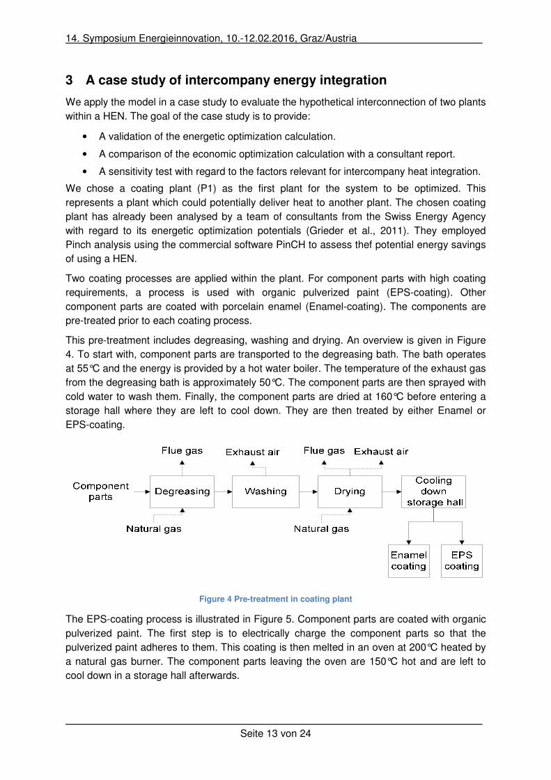
This pre-treatment includes degreasing, washing and drying. An overview is given in Figure
4. To start with, component parts are transported to the degreasing bath. The bath operates
at 55°C and the energy is provided by a hot water boiler. The temperature of the exhaust gas
from the degreasing bath is approximately 50°C. The component parts are then sprayed with
cold water to wash them. Finally, the component parts are dried at 160°C before entering a
storage hall where they are left to cool down. They are then treated by either Enamel or
EPS-coating.
Figure 4 Pre-treatment in coating plant
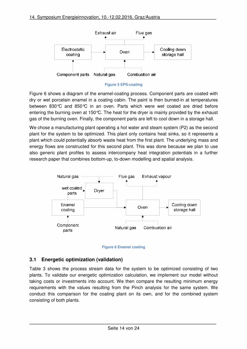
The EPS-coating process is illustrated in Figure 5. Component parts are coated with organic
pulverized paint. The first step is to electrically charge the component parts so that the
pulverized paint adheres to them. This coating is then melted in an oven at 200°C heated by
a natural gas burner. The component parts leaving the oven are 150°C hot and are left to
cool down in a storage hall afterwards.
14. Symposium Energieinnovation, 10.-12.02.2016, Graz/Austria
Seite 14 von 24
Figure 5 EPS-coating
Figure 6 shows a diagram of the enamel-coating process. Component parts are coated with
dry or wet porcelain enamel in a coating cabin. The paint is then burned-in at temperatures
between 830°C and 850°C in an oven. Parts which were wet coated are dried before
entering the burning oven at 150°C. The heat for the dryer is mainly provided by the exhaust
gas of the burning oven. Finally, the component parts are left to cool down in a storage hall.
We chose a manufacturing plant operating a hot water and steam system (P2) as the second
plant for the system to be optimized. This plant only contains heat sinks, so it represents a
plant which could potentially absorb waste heat from the first plant. The underlying mass and
energy flows are constructed for this second plant. This was done because we plan to use
also generic plant profiles to assess intercompany heat integration potentials in a further
research paper that combines bottom-up, to-down modelling and spatial analysis.
Figure 6 Enamel coating
3.1 Energetic optimization (validation)
Table 3 shows the process stream data for the system to be optimized consisting of two
plants. To validate our energetic optimization calculation, we implement our model without
taking costs or investments into account. We then compare the resulting minimum energy
requirements with the values resulting from the Pinch analysis for the same system. We
conduct this comparison for the coating plant on its own, and for the combined system
consisting of both plants.
14. Symposium Energieinnovation, 10.-12.02.2016, Graz/Austria
Seite 15 von 24
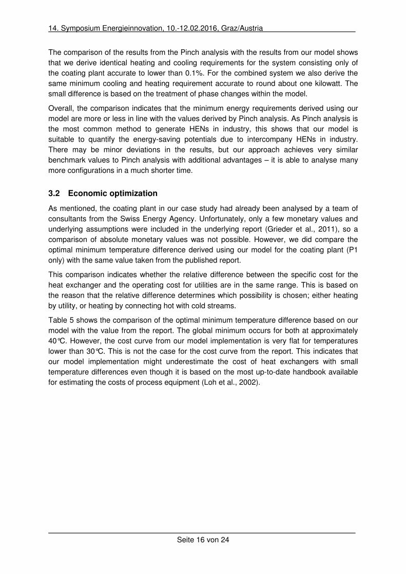
Table 3 Process stream data
Description Medium
Tin [°C]
Tout [°C]
cp [kJ/kg*K]
Q [kW] Plant
Degreasing , Hot bath Cold Water 55 60 16,840 157 P1
EPS oven, Hot cabin Cold Air 195 200 1,000 173 P1
Dryer enamel, Hot cabin Cold Air 145 150 1,000 157 P1
EPS oven, Combustion air Cold Air 9 55 1,004 9 P1
Dryer enamel, Combustion air Cold Air 9 55 1,004 3 P1
Dryer pre-treatment, Hot cabin Cold Air 155 160 1,100 173 P1
Degreasing , Exhaust air Hot Air 50 20 0,991 -73 P1
EPS oven, Flue gas Hot Air 260 20 1,104 -20 P1
EPS oven, Exhaust air Hot Air 200 20 1,004 -70 P1
Enamel oven, Exhaust vapour Hot Air 95 20 1,004 -70 P1
Dryer enamel, Exhaust air Hot Air 150 20 1,101 -33 P1
Dryer pre-treatment, Exhaust air Hot Air 160 20 1,303 -213 P1
Hot Water Cold Water 20 100 4,183 198 P2
Steam (incl. energy for vaporisation) Cold Water 100 200 2,042 463 P2
Steam Cold Water 200 500 1,975 26 P2
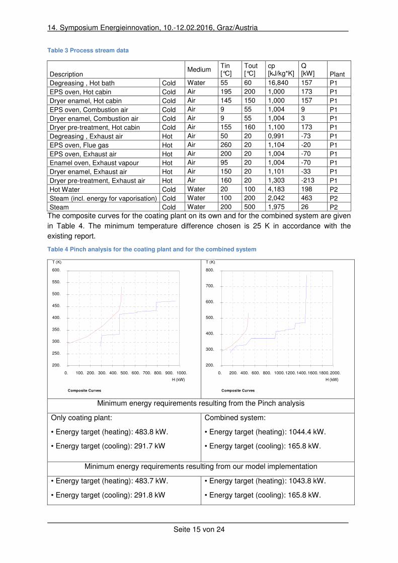
The composite curves for the coating plant on its own and for the combined system are given
in Table 4. The minimum temperature difference chosen is 25 K in accordance with the
existing report.
Table 4 Pinch analysis for the coating plant and for the combined system
Minimum energy requirements resulting from the Pinch analysis
Only coating plant:
• Energy target (heating): 483.8 kW.
• Energy target (cooling): 291.7 kW
Combined system:
• Energy target (heating): 1044.4 kW.
• Energy target (cooling): 165.8 kW.
Minimum energy requirements resulting from our model implementation
• Energy target (heating): 483.7 kW.
• Energy target (cooling): 291.8 kW
• Energy target (heating): 1043.8 kW.
• Energy target (cooling): 165.8 kW.
0. 100. 200. 300. 400. 500. 600. 700. 800. 900. 1000.
200.
250.
300.
350.
400.
450.
500.
550.
600.
H (kW)
T (K)
Composite Curves
0. 200. 400. 600. 800. 1000.1200.1400.1600.1800.2000.
200.
300.
400.
500.
600.
700.
800.
H (kW)
T (K)
Composite Curves
14. Symposium Energieinnovation, 10.-12.02.2016, Graz/Austria
Seite 16 von 24
The comparison of the results from the Pinch analysis with the results from our model shows
that we derive identical heating and cooling requirements for the system consisting only of
the coating plant accurate to lower than 0.1%. For the combined system we also derive the
same minimum cooling and heating requirement accurate to round about one kilowatt. The
small difference is based on the treatment of phase changes within the model.
Overall, the comparison indicates that the minimum energy requirements derived using our
model are more or less in line with the values derived by Pinch analysis. As Pinch analysis is
the most common method to generate HENs in industry, this shows that our model is
suitable to quantify the energy-saving potentials due to intercompany HENs in industry.
There may be minor deviations in the results, but our approach achieves very similar
benchmark values to Pinch analysis with additional advantages – it is able to analyse many
more configurations in a much shorter time.
3.2 Economic optimization
As mentioned, the coating plant in our case study had already been analysed by a team of
consultants from the Swiss Energy Agency. Unfortunately, only a few monetary values and
underlying assumptions were included in the underlying report (Grieder et al., 2011), so a
comparison of absolute monetary values was not possible. However, we did compare the
optimal minimum temperature difference derived using our model for the coating plant (P1
only) with the same value taken from the published report.
This comparison indicates whether the relative difference between the specific cost for the
heat exchanger and the operating cost for utilities are in the same range. This is based on
the reason that the relative difference determines which possibility is chosen; either heating
by utility, or heating by connecting hot with cold streams.
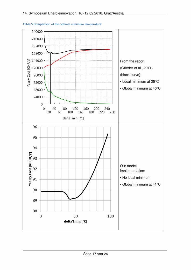
Table 5 shows the comparison of the optimal minimum temperature difference based on our
model with the value from the report. The global minimum occurs for both at approximately
40°C. However, the cost curve from our model implementation is very flat for temperatures
lower than 30°C. This is not the case for the cost curve from the report. This indicates that
our model implementation might underestimate the cost of heat exchangers with small
temperature differences even though it is based on the most up-to-date handbook available
for estimating the costs of process equipment (Loh et al., 2002).
14. Symposium Energieinnovation, 10.-12.02.2016, Graz/Austria
Seite 17 von 24
Table 5 Comparison of the optimal minimum temperature
From the report
(Grieder et al., 2011)
(black curve):
• Local minimum at 25°C
• Global minimum at 40°C
Our model
implementation:
• No local minimum
• Global minimum at 41°C
88
89
90
91
92
93
94
95
96
0 50 100
Ye
ar
lyC
os
t[k
EU
R/
y]
deltaTmin [°C]
14. Symposium Energieinnovation, 10.-12.02.2016, Graz/Austria
Seite 18 von 24
3.3 Sensitivity test
The sensitivity test was to see whether our model responds plausibly to the factors relevant
for intercompany heat integration. We generated HENs for the coating plant only and for the
system combing the coating plant with the manufacturing plant varying thermal loads,
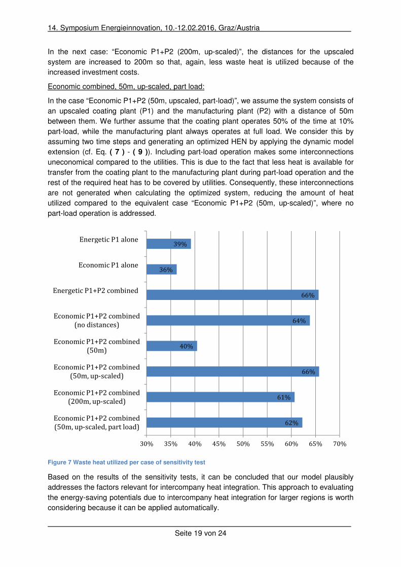
distances and load behaviour. An extract is given in Figure 7. In the following, we discuss the
results and present arguments for the model’s plausibility.
Energetic and Economic alone:
The sensitivity calculations “Energetic and Economic alone” represent optimized HENs for
the coating plant only (P1).
In the first case “Energetic P1 alone”, the HEN was generated based only on energetic
considerations. In the second case “Economic P1 alone”, additional investments in heat
exchangers were included, so that each energetically possible interconnection between heat
sink and source is benchmarked with its specific costs. The specific costs for utilities to
provide heat or cold for each heat sink or heat source were also taken into account. To
generate a HEN, the model decides whether the thermal needs for each heat sink and
source are best satisfied by connecting the heat sink and source by a heat exchanger or by
using utilities with regard to the overall objective function - minimizing the costs of the overall
system. Thus, sometimes it is cheaper to use utilities than to interconnect heat sources and
sinks. This can be seen in Figure 7. Figure 7 illustrates how much of the heat needed by all
the heat sinks is provided by heat exchangers between heat sources and sinks, i.e. how
much “waste heat” would be utilized in the HEN. It can be seen that less waste heat is
utilized for the case “Economic P1 alone” than for the case “Energetic P1 alone”.
Energetic and Economic combined:
The sensitivity calculations “Energetic and Economic combined” represent optimized HENs
for the system consisting of the coating plant (P1) and the manufacturing plant (P2). Again,
two HENs are generated; one based on energetic and one based on economic
considerations. Consequently, more waste heat would be utilized by a HEN in the case
“Energetic P1+P2 combined” than in the case “Economic P1+P2 (no distances)”. Please note
that, for the second case, no investments related to distances are taken into account.
Economic combined, 50m, 50m-upscaled and 200m-upsclaed:
In the case “Economic P1+P2 (50m)”, a HEN is generated for both plants taking into account
the investments for heat exchangers and those related to the distances between the sites
(e.g. for pipes), in this case for a distance of 50m. As a result, less waste heat is utilized than
in the case “Economic combined (no distances)”, as interconnections across company
borders have to compete with utilities situated at each site. The reason is that especially
potential interconnections where only small amounts of heat are transferred become not
competitive.
Then the amount of waste heat from the first plant is scaled up by increasing the thermal
loads in the case “Economic P1+P2 (50m, up-scaled)”. The result is that some
interconnections between P1 and P2 are now competitive compared to the utilities, so that
more waste heat is utilized than in the previous case with no upscaling.
14. Symposium Energieinnovation, 10.-12.02.2016, Graz/Austria
Seite 19 von 24
In the next case: “Economic P1+P2 (200m, up-scaled)”, the distances for the upscaled
system are increased to 200m so that, again, less waste heat is utilized because of the
increased investment costs.
Economic combined, 50m, up-scaled, part load:
In the case “Economic P1+P2 (50m, upscaled, part-load)”, we assume the system consists of
an upscaled coating plant (P1) and the manufacturing plant (P2) with a distance of 50m
between them. We further assume that the coating plant operates 50% of the time at 10%
part-load, while the manufacturing plant always operates at full load. We consider this by
assuming two time steps and generating an optimized HEN by applying the dynamic model
extension (cf. Eq. ( 7 ) - ( 9 )). Including part-load operation makes some interconnections
uneconomical compared to the utilities. This is due to the fact that less heat is available for
transfer from the coating plant to the manufacturing plant during part-load operation and the
rest of the required heat has to be covered by utilities. Consequently, these interconnections
are not generated when calculating the optimized system, reducing the amount of heat
utilized compared to the equivalent case “Economic P1+P2 (50m, up-scaled)”, where no
part-load operation is addressed.
Figure 7 Waste heat utilized per case of sensitivity test
Based on the results of the sensitivity tests, it can be concluded that our model plausibly
addresses the factors relevant for intercompany heat integration. This approach to evaluating
the energy-saving potentials due to intercompany heat integration for larger regions is worth
considering because it can be applied automatically.
62%
61%
66%
40%
64%
66%
36%
39%
30% 35% 40% 45% 50% 55% 60% 65% 70%
Economic P1+P2 combined
(50m, up-scaled, part load)
Economic P1+P2 combined
(200m, up-scaled)
Economic P1+P2 combined
(50m, up-scaled)
Economic P1+P2 combined
(50m)
Economic P1+P2 combined
(no distances)
Energetic P1+P2 combined
Economic P1 alone
Energetic P1 alone
14. Symposium Energieinnovation, 10.-12.02.2016, Graz/Austria
Seite 20 von 24
4 Summary
This contribution began by pointing out the current gaps with regard to assessing the
potential energy savings due to intercompany heat integration. A few case studies have been
made, but only one (element energy et al., 2014) has addressed the potential savings for an
entire region from utilizing waste heat, and also considered intercompany heat integration.
Element energy (2014) analysed the potential for recovering waste heat from industry in the
UK and included “over the fence” solutions, i.e. intercompany heat integration.
However, the modelling assumes a single source-sink technology combination and does not
include integrated heat networks. Furthermore, there are no known studies for Germany or
other countries. In addition, intercompany heat integration is not addressed as an efficiency
option in models of industrial energy demand projections. Thus, we argue that a framework
to systematically assess the energy-saving potentials due to intercompany heat integration
for regions might help to close these gaps; allowing structured studies for more regions and
the consideration of intercompany heat integration as a saving option in models of industrial
energy demand projection.
Second, we presented a model to evaluate the energy savings due to intercompany HENs
based on information about the heating and cooling requirements of the affected companies
and their distance to each other. The model operates using the transport algorithm and
represents a mathematical approach to generating HENs, which means it offers the
possibility to evaluate many cases automatically and quickly. This is a great advantage
compared to semi-automatic approaches such as Pinch analysis with regard to the overriding
problem - providing a framework to systematically estimate the energy-saving potentials due
to intercompany heat integration for regions.
Finally, we applied the model to evaluate a hypothetical case study of two plants. The results
indicate that the theoretical energy savings derived with our model are valid for combinations
of plants. The results are also very similar to those derived using Pinch analysis, which is the
most common approach to generating HENs in industry. If investments in heat integration
are also addressed, it can be further shown that the relevant factors concerning
intercompany heat integration such as the distance between plants, or possible part load
operation are also plausibly addressed.
5 Outlook
The model implemented here could be applied to a huge number of case studies
automatically to estimate the energy-saving potentials for regions due to intercompany heat
integration. To do so, first the region would have to be specified and data collected on the
heating and cooling requirements for the companies in that region. This data collection could
be done via expert interviews or surveys. As this approach is cost-intensive and time-
consuming, it is worth considering more generic approaches. For some energy-intensive
industries, commercial databases exist on plant locations (e.g. steel, pulp and paper
production, cement). These usually contain information on location, capacity and historical
production per year. As these industries are more or less homogeneous with regard to the
production processes applied, generic “bottom-up modelled” process schemes could be
developed for them. The cooling and heating requirements for the plants contained in the
14. Symposium Energieinnovation, 10.-12.02.2016, Graz/Austria
Seite 21 von 24
databases could then be differentiated by temperature depending on the activity data
contained in the databases (i.e. production per year). As energy-intensive industries often
have still unused waste heat (Persson et al.,2014), this would at least capture the
energetically-relevant companies for intercompany heat integration.
Some commercial databases also exist for non-energy-intensive companies, which contain
financial figures such as turnover differentiated by company or site (i.e. Hoppenstedt,
http://www.hoppenstedt-firmendatenbank.de). Analysing economic sectors with regard to
energy costs and applied fuels and combining this with information on the typical
temperature ranges applied in each sector (Wagner, 2002) allows the construction of generic
plant profiles for non-energy-intensive sites. Non-energy-intensive plants could then at least
be represented by a set of heat sinks in specific temperature ranges. Based on these data,
promising combinations of sites for intercompany HENs could be identified.
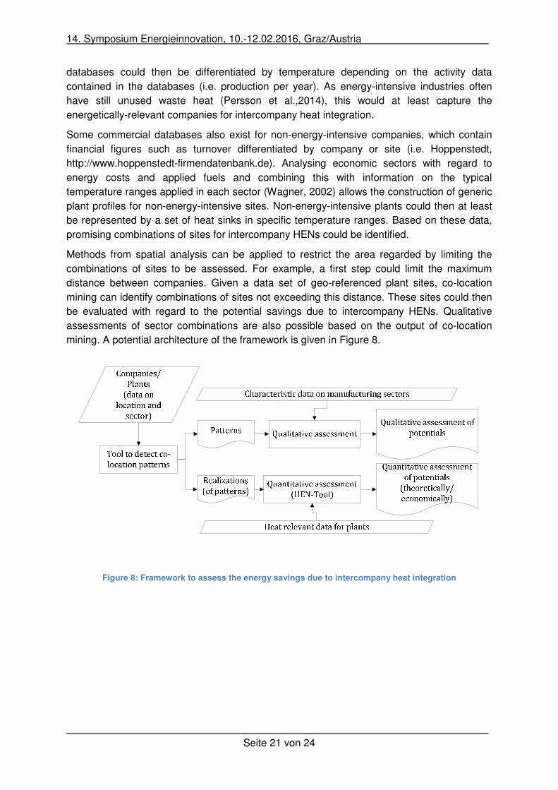
Methods from spatial analysis can be applied to restrict the area regarded by limiting the
combinations of sites to be assessed. For example, a first step could limit the maximum
distance between companies. Given a data set of geo-referenced plant sites, co-location
mining can identify combinations of sites not exceeding this distance. These sites could then
be evaluated with regard to the potential savings due to intercompany HENs. Qualitative
assessments of sector combinations are also possible based on the output of co-location
mining. A potential architecture of the framework is given in Figure 8.
Figure 8: Framework to assess the energy savings due to intercompany heat integration
14. Symposium Energieinnovation, 10.-12.02.2016, Graz/Austria
Seite 22 von 24
6 References
Ahmad, S., Linnhoff, B., Smith, R., 1990. Cost optimum heat exchanger networks—2. targets and design for detailed capital cost models. Computers & Chemical Engineering, 14, 751–767.
BMWi, 2014. National Action Plan on Energy Efficiency (NAPE). http://www.bmwi.de/BMWi/Redaktion/PDF/M-O/nape-national-action-plan-on-energy-efficiency,property=pdf,bereich=bmwi2012,sprache=de,rwb=true.pdf (22 January, 2016).
Broberg, S., Backlund, S., Karlsson, M., Thollander, P., 2012. Industrial excess heat deliveries to Swedish district heating networks. Drop it like it's hot. Energy Policy, 51, 332–339.
Broberg Viklund, S., Johansson, M.T., 2014. Technologies for utilization of industrial excess heat. Potentials for energy recovery and CO2 emission reduction. Energy Conversion and Management, 77, 369–379.
Cerda, J., Westerberg, A.W., Mason, D., Linnhoff, B., 1983. Minimum utility usage in heat exchanger network synthesis A transportation problem. Chemical Engineering Science, 38, 373–387.
Chen, Y., Grossmann, I.E., Miller, D.C., 2015. Computational strategies for large-scale MILP transshipment models for heat exchanger network synthesis. Computers & Chemical Engineering, 82, 68–83.
Ciric, A.R., Floudas, C.A., 1989. A retrofit approach for heat exchanger networks. Computers & Chemical Engineering, 13, 703–715.
Element Energy, Ecofys, Imperial College, Stevenson, P., 2014. The potential for recovering and using surplus heat from industry. https://www.gov.uk/government/publications/the-potential-for-recovering-and-using-surplus-heat-from-industry (22 January, 2016).
Escobar, M., Trierweiler, J.O., 2013. Optimal heat exchanger network synthesis. A case study comparison. Applied Thermal Engineering, 51, 801–826.
Fichtner, W., Frank, M., Rentz, O., 2004. Inter-firm energy supply concepts. An option for cleaner energy production. Journal of Cleaner Production, 12, 891–899.
Fourer, R., Gay, D.M., Kernighan, B.W., 2003. AMPL. A modeling language for mathematical programming, 2nd ed. Thomson/Brooks/Cole, Pacific Grove, CA.
Geldermann, J., Treitz, M., Rentz, O., 2006. Integrated technique assessment based on the pinch analysis approach for the design of production networks. European Journal of Operational Research, 171, 1020–1032.
Grieder, T., DM Energieberatung AG, 2011. Prozessoptimierung mit der Pinch-Methode V-Zug AG. SCHLUSSBERICHT.
Hiete, M., Ludwig, J., Schultmann, F., 2012. Intercompany Energy Integration. Journal of Industrial Ecology, 16, 689–698. http://dx.doi.org/10.1111/j.1530-9290.2012.00462.x.
Hills, T., Gambhir, A., Fennell, P.S., 2014. The suitability of different types of industry for inter-site heat integration. in: European Council for an Energy-Efficient Economy (Ed.), ECEEE 2014 Industrial Summer Study: conference proceedings, Arnhem 2014. Retool for a competitive and sustainable industry. ECEEE, Stockholm.
Hummel, M., Kranzl, L., Villotti, C., 2014. Assessment of the economic viability of the integration of industrial waste heat into existing district heating grids. in: European Council for an Energy-Efficient Economy (Ed.), ECEEE 2014 Industrial Summer Study: conference proceedings, Arnhem 2014. Retool for a competitive and sustainable industry. ECEEE, Stockholm, pp. 537–545.
14. Symposium Energieinnovation, 10.-12.02.2016, Graz/Austria
Seite 23 von 24
Kattenstein, T., Draht, T., Ziolek A., Unger H., Wagner H.-J., 2002. Validierung und kommunale Disaggregierung des Expertensystems HERAKLES, Bochum.
Kemp, I.C., 2007. Pinch analysis and process integration. A user guide on process integration for the efficient use of energy, 2nd ed. Butterworth-Heinemann, Oxford.
Klotz, E.-M., Koepp, M., Peter, F., Thamling, N., Wünsch, M., Ziegenhagen, I., Eikmeier, B., Fette, M., Janßen, K., Jochem, E., Reitze, F., Schön, M., Toro, F., Gailfuß, M., 2014. Potenzial- und Kosten-Nutzen-Analyse zu den Einsatzmöglichkeiten von Kraft-Wärme-Kopplung(Umsetzung der EU-Energieeffizienzrichtlinie) sowie Evaluierung des KWKG im Jahr 2014.
Koraviyotin, S., Kitipat, S., 2015. Heat Exchanger Network Synthesis/Retrofit using MINLPStage-wise Superstructure with Non-isothermal Mixing. in: Sauro Pierucci, Jirí J. Klemeš (Ed.), CHEMICAL ENGINEERING TRANSACTIONS. online Volume 43, 2015, pp. 1273–1279.
Linnhoff, B., Ahmad, S., 1990. Cost optimum heat exchanger networks—1. Minimum energy and capital using simple models for capital cost. Computers & Chemical Engineering, 14, 729–750.
Linnhoff, B., Flower, J.R., 1978. Synthesis of heat exchanger networks. I. Systematic generation of energy optimal networks. AIChE Journal, 24, 633–642.
Loh H.P., Lyons, J., White, C., 2002. Process Equipment Cost Estimation - Final Report (27 January, 2016).
Ludwig, J.M., 2012. Energieeffizienz durch Planung betriebsübergreifender Prozessintegration mit der Pinch-Analyse. KIT Scientific Publishing; Technische Informationsbibliothek u. Universitätsbibliothek, Karlsruhe, Hannover.
Natural Resources Canada, 2003. Pinch Analysis: For the Efficient Use of Energy, Water and Hydrogen (27 January, 2016).
Papoulias, S.A., Grossmann, I.E., 1983. A structural optimization approach in process synthesis—II. Computers & Chemical Engineering, 7, 707–721.
Pehnt, M., 2010. Energieeffizienz. Ein Lehr- und Handbuch. Springer-Verlag Berlin Heidelberg, Berlin, Heidelberg.
Pehnt, M., Bodeker, J., Arens, M., Jochem, E., Idrissova, F., 2011. Industrial waste heat‐tapping into a neglected efficiency potential. in: European Council for an Energy-Efficient Economy (Ed.), Energy efficiency first: the foundation of a low-carbon society. ECEEE 2011 Summer Study : conference proceedings, 6-11 June 2011, Belambra Presquile de Giens, France. ECEEE, Stockholm, pp. 691–700.
Persson, U., Möller, B., Werner, S., 2014. Heat Roadmap Europe. Identifying strategic heat synergy regions. Energy Policy, 74, 663–681.
Radgen, P., Lucas, K., 1996. Energy system analysis of a fertilizer complex - Pinch analysis vs. Exergy analysis. Chemical Engineering & Technology, 19, 192–195.
Rašković, P., Stoiljković, S., 2009. Pinch design method in the case of a limited number of process streams. Energy, 34, 593–612.
Rohde, C., 2013. Erstellung von Anwendungsbilanzen für das Jahr 2012 für das verarbeitende Gewerbe mit Aktualisierungen für die Jahre 2009-2011. http://www.ag-energiebilanzen.de/ (27 January, 2016).
Roman Hackl, Eva Andersson, Simon Harvey, 2011. Targeting for energy efficiency and improved energy collaboration between different companies using total site analysis (TSA). Energy, 36, 4609–4615. http://www.sciencedirect.com/science/article/pii/S0360544211001897.

14. Symposium Energieinnovation, 10.-12.02.2016, Graz/Austria
Seite 24 von 24
Sächsische Energieagentur GmbH (SAENA), 2012. Technologien zur Abwärmenutzung. http://www.saena.de/download/Broschueren/BU_Technologien_der_Abwaermenutzung.pdf (27 January, 2016).
Sauro Pierucci, Jirí J. Klemeš (Ed.), 2015. CHEMICAL ENGINEERING TRANSACTIONS. online Volume 43, 2015.
Sieniutycz, S., Jeżowski, J., 2013. Energy optimization in process systems and fuel cells, Second edition. Elsevier Science, Oxford.
Smith, R., 2005. Chemical process design and integration. Wiley, Chichester, West Sussex, England, Hoboken, NJ.
Yee, T.F., Grossmann, I.E., 1990. Simultaneous optimization models for heat integration—II. Heat exchanger network synthesis. Computers & Chemical Engineering, 14, 1165–1184.