Embed Size (px)
Citation preview
MPSL-DFG Field Sampling Team SOP Procedure Number: 1.0 Standard Operating Procedures (SOPs) for Conducting Field Measurements and Field Collections of Water and Bed Sediment Samples in SWAMP
Date: 15 October 2007
MPSL-DFG_FieldSOP_v1.0 Page: 1 of 64 Marine Pollution Studies Laboratory – Department of Fish and Game (MPSL-DFG) Standard Operating Procedures (SOPs) for Conducting Field Measurements and Field Collections of Water and Bed Sediment Samples in the Surface Water Ambient Monitoring Program (SWAMP) The SOPs below are for reference and information purposes only, the documents are not required by the Surface Water Ambient Monitoring Program (SWAMP). Please see the SWAMP Quality Assurance Management Plan ( http://www.swrcb.ca.gov/swamp/qamp.html ) for more information regarding SWAMP QA/QC requirements.
Table of Contents Field Measurements…………………………………………………………………………….2 Field Collection Procedures for Water Samples…………………………………………………………………………………………30 Field Collection Procedures for Bed Sediment Samples……………………………………................................................................................58
MPSL-DFG Field Sampling Team SOP Procedure Number: 1.0 Standard Operating Procedures (SOPs) for Conducting Field Measurements and Field Collections of Water and Bed Sediment Samples in SWAMP
Date: 15 October 2007
MPSL-DFG_FieldSOP_v1.0 Page: 2 of 64
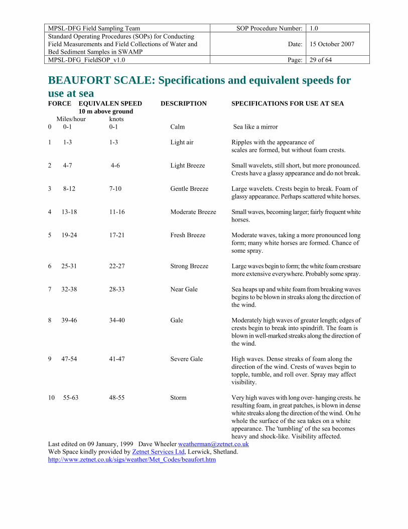
Field Measurements Field Data Sheets Field data sheets are used to record field observations, probe measurements, and water and sediment chemistry sampling. Field data sheets are provided through the Marine Pollution Studies Laboratory website at: http://mpsl.mlml.calstate.edu/swdwnlds.htm Click on the Field Data Sheets for the most recent versions. There are guidelines provided below to standardize what is recorded on all data sheets and that should be helpful in completing each form. The Beaufort Scale (see at the end of this document) is also used for specifications and equivalent wind speeds for water conditions. The entries discussed below and on the field data sheets are recorded at each sampling site.
Notes to Standardize SWAMP Field Data Sheets
(For in the field use) Upon arrival at a sampling site, record visual observations on the appearance of the water and other information related to water quality and water use. Key Reminders to identify samples:
1. Sample Time is the SAME for all samples (Water, Sediment, & Probe) taken at the sampling event. Use time of FIRST sample as it is important for the chain of custody (COC).
2. Left Bank/Right Bank Left bank is defined as the bank to the left of the observer when facing downstream, and the right bank is to the right of the observer when facing downstream
FIELD OBSERVATIONS: (each one of these observations has a Comment field in the database so use comment space on data sheet to add information about an observation if necessary)
1. DOMINANT SUBSTRATE: if possible; describe DOMINANT substrate type; use UNK if you cannot see the dominant substrate type
2. WADEABILITY: in general, is the water body being sampled wadeable to the average person AT the POINT of SAMPLE
3. BEAUFORT SCALE: use scale 0-12; refer to scales listed at the end of this document. 4. WIND DIRECTION: records the direction from which the wind is blowing 5. PICTURES: Digital photos are taken to help document the actual sampling site. The
convention is to take photos facing DOWNSTREAM, overlooking the site. Right bank and left bank are thus defined in this downstream-facing direction. Document any discrepancies from this convention. Only one photo is necessary, if both, left and right
MPSL-DFG Field Sampling Team SOP Procedure Number: 1.0 Standard Operating Procedures (SOPs) for Conducting Field Measurements and Field Collections of Water and Bed Sediment Samples in SWAMP
Date: 15 October 2007
MPSL-DFG_FieldSOP_v1.0 Page: 3 of 64
bank, fit into one frame. Record all photos in the field data sheet space to record picture numbers given by camera; be sure to rename accordingly back in the office. All photos should be renamed and saved with the StationCode_yyyy_mm_dd_uniquecode (e.g. 123ABC123_2007_07_01_BBDS).
6. SITE ODOR: Note if hydrogen sulfide odor, musty odor, sewage odor, etc. is in the sampling reach
7. SKY CODE: Note recent meteorological events that may have impacted water quality 8. OTHER PRESENCE: VASCULAR refers to terrestrial plants or submerged aquatic
vegetation (SAV) and NONVASCULAR refers to plankton, periphyton etc. 9. PRECIPITATION: Note if any precipitation is occurring during sampling 10. PRECIPITATION LAST 24 HOURS: Note how much precipitation has occurred
within the last 24-h of sampling 11. WATER ODOR: Note if the sample water being collected has odor 12. WATER CLARITY: this describes the clarity of the water while standing creek side;
clear represents water that is clear to the bottom, cloudy may not be clear to bottom but greater than 4” can be seen through the water column.
13. WATER COLOR: This is the color of the water from standing creek side 14. OBSERVED FLOW: Visual estimates in cubic ft/s.
SAMPLE DETAILS: 1. EVENT TYPE: Note the event type based which type of media is being collected 2. SAMPLE TYPE: GRAB samples are when bottles are filled from a single depth;
INTEGRATED sample are taken from MULTIPLE depths and combined. a. GRAB: use 0.1 for subsurface samples; if too shallow to submerge bottle; depth =0 b. INTEGRATED: -88 in depth sampled, record depths combined in sample comments
3. SAMPLING CREW: J. Smith, S. Ride (first person listed is crew leader) 4. STARTING BANK: Which side of the stream was accessed first. Bearings are always
recorded looking downstream 5. OCCUPATION METHOD: What media was used to access the site 6. TARGET LAT/LONG: Refers to the existing station location that the sampling crew is
trying to achieve; can be filled out prior to sampling 7. ACTUAL LAT/ LONG: is the location of the current sample event. 8. SAMPLE LOCATION: describes from where IN water body sample was taken: Can be
combined; ex: bank/thalweg or midchannel /thalweg 9. HYDROMODIFICATION: Describe existing hydromodifications such as a grade
control, drainage pipes, bridge, culvert 10. HYDROMOD LOC: if there was an IMMEDIATE (with in range potentially effecting
sample) hydromodification; was sample taken upstream or downstream of modification; if there is no hydromodification, NA is appropriate
11. STREAM DEPTH, WIDTH & DISTANCE FROM BANK: describe in meters at point of sample. Distance from bank should be recorded from the starting bank
MPSL-DFG Field Sampling Team SOP Procedure Number: 1.0 Standard Operating Procedures (SOPs) for Conducting Field Measurements and Field Collections of Water and Bed Sediment Samples in SWAMP
Date: 15 October 2007
MPSL-DFG_FieldSOP_v1.0 Page: 4 of 64 Field Data Logbook A Field Data Logbook or a Field Folder is taken into the field on each sampling trip. The use of bound or loose-leaf notebooks is left up to the entity conducting the monitoring. A good safety precaution against the loss of a bound field data logbook is to photocopy the current pages upon returning from the field. These pages are kept on file at the specific sample collection entity’s office. If a loose-leaf notebook is used, take care to remove original field data log sheets from the notebook and file in the office. Copies of the field data log sheets may be left in the notebook for future reference. Field Data Logbooks (bound or loose leaf sheets) are maintained on file indefinitely in each regional office or contract laboratory office. They are never discarded, since the logbook may be the only written record of field measurements. Field Data Logbooks are reviewed periodically during SWAMP QA site visits. At this point, these field notes are not inclusive of the information that would be collected for biological assessment work, and several other data measurement types. Flow Sampling crews should be notified on reconnaissance forms if it is known that there is an operational United States Geological Survey (USGS) gage is located at or nearby a sampling site. If there is a USGS gage nearby, a gage height in feet is recorded and later converted to an instantaneous flow value and recorded in the logbook. The gage height is always to be reported to the USGS for conversion to flow. If a USGS gage is not available, a flow measurement should be taken, if requested. See Instantaneous Flow Measurement information starting on page 13 in this document. In addition, it is recommended that a flow severity value is recorded at each stream or river station that is not tidally influenced. See the Flow Severity section starting on page 13 of this document. Centroid velocity measurements may also be taken as a minimum acceptable rough characterization of the stream flow as requested, although this measurement is not to be recorded as a flow, since it is only a velocity measurement. Record of Samples Collected for Purposes of Chemical Analysis The general types of chemical samples to be collected are listed for each site, since this may vary from site-to-site (e.g., metals-in-water, pesticides-in-sediments, routine water quality). Analyses authorization forms are recommended since different authorized laboratories perform different chemical analyses. The method of preservation for each chemical sample is recorded, as appropriate. Record of Data Submission The Logbook field must indicate in some manner whether data recorded in the logbook has been transcribed onto data forms and submitted to the SWAMP data management staff.
MPSL-DFG Field Sampling Team SOP Procedure Number: 1.0 Standard Operating Procedures (SOPs) for Conducting Field Measurements and Field Collections of Water and Bed Sediment Samples in SWAMP
Date: 15 October 2007
MPSL-DFG_FieldSOP_v1.0 Page: 5 of 64 Other Observations Water Appearance
Sediment Appearance
Note general appearance (e.g., color, unusual amount of suspended matter, debris or foam)
Color, Odor and sediment composition should be noted. Weather
Note recent meteorological events that may have impacted water quality; (e.g., heavy rains, cold front, very dry, very wet)
Biological Activity
Note excessive macrophyte, phytoplankton or periphyton growth. The observation of water color and excessive algal growth is very important in explaining high chlorophyll a values. Other observations such as presence of fish, birds and spawning fish are noted.
Watershed or Instream Activities
Note instream or drainage basin activities or events that are impacting water quality (e.g., bridge construction, shoreline mowing, livestock watering upstream).
Record of Pertinent Observations Related to Water Quality and Stream Uses
If the water quality conditions are exceptionally poor, note that standards are not met in the observations, (e.g., dissolved oxygen is below minimum criteria). Note uses (e.g., swimming, wading, boating, fishing, irrigation pumps, navigation). Eventually, for setting water quality standards, the level of use will be based on comments related to the level of fishing and swimming activities observed at a station.
Specific Sample Information
Note specific comments about the sample itself that may be useful in interpreting the results of the analysis (e.g., number of sediment grabs, or type and number of fish in a tissue sample). If the sample was collected for a complaint or fish kill, make a note of this in the observation section.
Missing Parameters
If a scheduled parameter or group of parameters is not collected, make some note of this in the comments.
Field Data Measurements While collecting water samples (see Field Collection Procedures for Water Samples section), record appropriate field measurements. When field measurements are made with a multiparameter instrument, it is preferable to place the sonde in the body of water to be sampled and allow it to equilibrate in the dissolved oxygen (D.O.) mode while water samples are collected. Field measurements are made at the centroid of flow, if the stream visually appears to be completely mixed from shore to shore. Centroid is defined as the midpoint of that portion of the stream width which contains 50% of the total flow. For routine field measurements, the date, time and depth are reported as a grab. Measure Quality Objectives (MQO’s) for field measurements are listed in appendix C of the SWAMP QAMP.
MPSL-DFG Field Sampling Team SOP Procedure Number: 1.0 Standard Operating Procedures (SOPs) for Conducting Field Measurements and Field Collections of Water and Bed Sediment Samples in SWAMP
Date: 15 October 2007
MPSL-DFG_FieldSOP_v1.0 Page: 6 of 64 Recommended Depths for Conducting Field Data Measurements Water Depth Less than 5 ft (<1.5 m)
If the water depth is less than 5 ft (1.5 m), grab samples for water are taken at approximately 0.1 m (4 in.), and multi-probe measurements are taken at approximately 0.2 m (8 in.). This is because all sensors have to be submerged, so 0.1 m would not be deep enough. But taking a grab sample at 0.2 m is not always feasible, as it is difficult to submerge bottles to that depth, and in many cases the bottle will hit the stream bottom.
Water Depth Greater than 5 ft (>1.5 m)
If the water depth at the sampling point exceeds 5 ft (1.5 m) in depth, a vertical profile of dissolved oxygen, temperature, pH and specific conductance are made using the multiparameter probe equipment. The depth of the sonde at the time of measurement is most accurately determined from the depth sensor on the multiparameter sonde rather than depth labels on the cable.
Vertical Depth Profiles and Depth-Integrated Sample Collection
If depth integration sampling is being conducted, or if vertical profile measurements are requested, multi-probe measurements are made starting at a depth of 0.2 m, and are then conducted at 1.0, 2.0, 3.0, 4.0, and 5.0 m depths after that until 5.0 m depth is reached. Beginning at 5.0 m, measurements are made every 5.0 m through depth profile.
Field data for multiparameter vertical depth profiles are recorded in final form on the SWAMP Field Data Sheets and submitted to the SWAMP data management staff. Go to http://mpsl.mlml.calstate.edu/swdwnlds.htm for detailed information on data reporting. Water Temperature (OC) Water temperature data are recorded for each SWAMP visit in final form in a Field Data Logbook and submitted to the SWAMP data management staff. See http://mpsl.mlml.calstate.edu/swdwnlds.htm for detailed information on data reporting.
Temperature Sampling Procedures Temperature is measured in-stream at the depth(s) specified above. Measuring temperature directly from the stream by immersing a multiprobe instrument or thermometer is preferred.
Hand Held Centigrade Thermometer If an electronic meter is not available, the temperature is measured with a hand-held, centigrade thermometer (Rawson, 1982).
< In wadeable streams, stand so that a shadow is cast upon the site for temperature measurement.
MPSL-DFG Field Sampling Team SOP Procedure Number: 1.0 Standard Operating Procedures (SOPs) for Conducting Field Measurements and Field Collections of Water and Bed Sediment Samples in SWAMP
Date: 15 October 2007
MPSL-DFG_FieldSOP_v1.0 Page: 7 of 64
< Hold the thermometer by its top and immerse it in the water. Position the thermometer so that the scale can be read.
< Allow the thermometer to stabilize for at least one minute, then without removing the thermometer from the water, read the temperature to the nearest 0.1o C and record.
< Do not read temperature with the thermometer out of the water. Temperature readings made with modern digital instruments are accurate to within +_ 0.1o C.
Temperature Measurement from a Bucket When temperature cannot be measured in-stream, it can be measured in a bucket-Nalgene or plastic. Care must be taken to insure a measurement representative of in-stream conditions. The following conditions must be met when measuring temperature from a bucket:
< The bucket must be large enough to allow full immersion of the probe or thermometer.
< The bucket must be brought to the same temperature as the water before it is filled. < The probe must be placed in the bucket immediately, before the temperature changes. < The bucket must be shaded from direct sunlight and strong breezes prior to and
during temperature measurement. < The probe is allowed to equilibrate for at least one minute before temperature is
recorded. < After these measurements are made, this water is discarded and another sample is
drawn for water samples which are sent to the laboratory. pH (standard units) pH data is recorded for each SWAMP visit in final form on the Field Data Sheets and submitted to the SWAMP data management staff. See http://mpsl.mlml.calstate.edu/swdwnlds.htm for detailed information on data reporting. pH Sampling Equipment The pH meter should be calibrated according to the recommended procedures for calibration and maintenance of SWAMP field equipment. Calibration directions are listed in the manufactures field equipment operations manual. The pH function is pre and post calibrated every 24 h of use for multiparameter instruments. pH Sampling Procedures In-stream Method Preferably, pH is measured directly in-stream at the depth(s) specified earlier in this document. Allow the pH probe to equilibrate for at least one minute before pH is recorded to the nearest 0.1 pH unit. pH Measurement from a Bucket When pH cannot be measured in-stream, it can be measured in a bucket-Nalgene or plastic. The following precautions are outlined above; “Temperature Measurement from a Bucket”.
MPSL-DFG Field Sampling Team SOP Procedure Number: 1.0 Standard Operating Procedures (SOPs) for Conducting Field Measurements and Field Collections of Water and Bed Sediment Samples in SWAMP
Date: 15 October 2007
MPSL-DFG_FieldSOP_v1.0 Page: 8 of 64 Potential Problems < If the pH meter value does not stabilize in several minutes, out gassing of carbon dioxide or hydrogen sulfide, or the settling of charged clay particles may be occurring (Rawson, 1982).
< If out gassing is suspected as the cause of meter drift, collect a fresh sample, immerse the pH probe and read pH at one minute.
< If suspended clay particles are the suspected cause of meter drift, allow the sample to settle for 10 min, then read the pH in the upper layer of sample without agitating the sample.
< With care, pH measurements can be accurately measured to the nearest 0.1 pH unit. Dissolved Oxygen (mg/L) Dissolved oxygen (D.O.) data is recorded for each SWAMP visit in final form on a Field Data Sheet and submitted to the SWAMP data management staff. See http://mpsl.mlml.calstate.edu/swdwnlds.htm for detailed information on data reporting. Dissolved Oxygen Sampling Equipment The dissolved oxygen meter should be calibrated according to the recommended procedures for calibration and maintenance of SWAMP field equipment. Calibration directions are listed in the manufactures field equipment operations manual.
Multiprobe Instrument Pre and post calibrate the D.O. sensor every 24 h and for elevations greater than 500 ft on the multiprobe instrument. Preferably, D.O. is measured directly in-stream at the depth(s) specified in the Field Measurements section above. The D.O. probe must equilibrate for at least 90 s before D.O. is recorded to the nearest 0.1 % saturation or mg/L. Care must be taken at profile stations to insure that the reading is stable for each depth. Since dissolved oxygen takes the longest to stabilize, record this parameter after temperature, conductivity and pH. If the D.O. probe has an operable, automatic stirrer attached, the D.O. probe does not have to be manually stirred. However, if the probe is not equipped with an automatic stirrer, manual stirring must be provided by raising and lowering the probe at a rate of 1 ft/s (0.3m/s) without agitating the water surface. If the stream velocity at the sampling point exceeds 1 ft/s, the probe membrane can be pointed upstream into the flow and manual stirring can be avoided (Rawson, 1982). D.O. Measurement from a Bucket When D.O. cannot be measured in-stream, it can be measured in a bucket-Nalgene or plastic, following precautions outlined in the Temperature Measurement from a Bucket listed above. During equilibration and reading, water should be moved past the membrane surface at a velocity of 1 ft/s (0.3 m/sec), either by automatic stirrer or manual stirring. If stirred manually in a bucket, the water surface is not agitated (Rawson, 1982).
MPSL-DFG Field Sampling Team SOP Procedure Number: 1.0 Standard Operating Procedures (SOPs) for Conducting Field Measurements and Field Collections of Water and Bed Sediment Samples in SWAMP
Date: 15 October 2007
MPSL-DFG_FieldSOP_v1.0 Page: 9 of 64 24-Hour Average D.O. (if requested in special study) Unattended 24-Hour D.O. Data Collection Why Collect 24-Hour Data Dissolved oxygen sampling for standards compliance is targeted to water bodies where low instantaneous D.O. levels indicate partial or nonsupport of designated aquatic life uses. Intensive monitoring is conducted with automated equipment that is preset to record and store field measurements hourly over one 24-h period. Four or more dissolved oxygen measurements may also be made manually at 4-6-h intervals over one 24-h period, as long as one is made near sunrise (0500-0900 h) to approximate the daily minimum. However, data collected with automated equipment is preferred. When to Take Measurements All 24-h D.O. monitoring events must be spaced over an index period representing warm-weather seasons of the year (approx March 15-October 15), with between one-half to two-thirds of the measurements occurring during the critical period (July 1-September 30). The critical period of the year is when minimum stream flows, maximum temperatures, and minimum dissolved oxygen concentrations typically occur in area streams. A flow measurement must be taken at the time of deployment. In a perennial stream, a 24-h data for standards compliance can not be used if the flow is less than the 7Q2. In perennial streams, the D.O. criterion to do not apply for flows under the 7Q2. A period of about one month must separate each 24-h sampling event. Additional samples may be collected outside the index period to further characterize a water body, but that information is generally not used for assessing standards compliance. Frequency of Measurements The measurement interval should be no more than once per 15 min and no less than once per hour. Where to Take Measurements For purposes of determining standards compliance with the 24-h average criteria, samples collected near the surface will be considered representative of the mixed surface layer. In deep streams, reservoirs, and tidally influenced water bodies, automated equipment is positioned between 1 foot (from the surface) to one-half the depth of the mixed surface layer. At least 10 24-h monitoring events (using the 24-h criteria and/or absolute minimum criteria) at each site within a 5-year period are recommended to provide adequate data for assessment. When to Collect Other Routine Samples, if doing 24-hour D.O. measurements Other routine field measurements and water samples should be collect at either the time of deployment, at the reference check, or when the multiprobe recording 24-h data is retrieved. When ever possible, flow must be measured at the 24-h site. Priority for Scheduling 24-Hour Sampling Events
< 303d listed waterbodies < Waterbodies with Concerns for DO problems (too few samples available for full use
assessment).
MPSL-DFG Field Sampling Team SOP Procedure Number: 1.0 Standard Operating Procedures (SOPs) for Conducting Field Measurements and Field Collections of Water and Bed Sediment Samples in SWAMP
Date: 15 October 2007
MPSL-DFG_FieldSOP_v1.0 Page: 10 of 64
< Occurrence of low D.O. concentrations observed during the day < Waterbodies with trends indicating declining D.O. concentrations < Waterbodies which would contribute to an Ecoregion data set
Data Reporting for 24-hour D.O. measurements Dissolved oxygen values recorded over the 24-h period are summed and divided by the number of measurements to determine the average concentration, which is compared to the 24-h criterion. The lowest D.O. value from each 24-h set is compared to the minimum criterion. There will be occasions when a complete 24-h data set won’t be possible. For example, if there are 18 measurements instead of 24, a time weighted diurnal average needs to be calculated. This can be easily done using GW Basic. Support of assigned aquatic life use is based on 24-h D.O. average and minimum criteria for each monitoring event. Report the 24-h average D.O. value, number of measurements over a 24-h period, and the minimum, and maximum values. Report data as a time composite sample with a beginning and ending date and time, covering the 24-h period measured.
Specific Conductance (µS/cm)
Specific conductance should be recorded for each SWAMP visit in final form on a Field Data Sheet and submitted to the SWAMP data management staff. See http://mpsl.mlml.calstate.edu/swdwnlds.htm for detailed information on data reporting. Specific Conductance Sampling Equipment The conductivity meter should be calibrated according to the recommended procedures for calibration and maintenance of SWAMP field equipment. Calibration directions are listed in the manufactures field equipment operations manual. Specific Conductance Sampling Procedure Preferably, conductivity is measured directly in-stream at the depth(s) specified earlier in this document. Allow the conductivity probe to equilibrate for at least one minute before specific conductance is recorded to three significant figures (if the value exceeds 100). The primary physical problem in using a specific conductance meter is entrapment of air in the conductivity probe chambers. The presence of air in the probe is indicated by unstable specific conductance values fluctuating up to _+100 µS/cm. The entrainment of air can be minimized by slowly, carefully placing the probe into the water; and when the probe is completely submerged, quickly move it through the water to release any air bubbles. If specific conductance cannot be measured in-stream, it should be measured in the container it can be measured in a bucket-Nalgene or plastic. The following precautions are outlined above; “Temperature Measurement from a Bucket”. Salinity (parts per thousand--ppt, or ‰) The value for salinity is computed from chloride concentration or specific conductance. The calculation assumes a nearly constant ratio for major ions in an estuary when seawater is diluted
MPSL-DFG Field Sampling Team SOP Procedure Number: 1.0 Standard Operating Procedures (SOPs) for Conducting Field Measurements and Field Collections of Water and Bed Sediment Samples in SWAMP
Date: 15 October 2007
MPSL-DFG_FieldSOP_v1.0 Page: 11 of 64 by river water. This assumption does not hold for cases where salinity is less than about three parts per thousand. Salinity determinations at such low values are only approximate. In estuarine waters, salinity is a relevant and meaningful parameter. Often the salinity may be low, approaching that of freshwater. Nevertheless, this is useful information. Determine if a station is estuarine from historical records (i.e., experiences cases where salinity is >2.0 ppt) and always report salinity at this station, regardless of the salinity during periods of high flow. Salinity is measured directly in-stream at the depth(s) specified earlier in this document. Salinity data should be recorded for each SWAMP visit in final form on a Field Data Sheet and submitted to the SWAMP data management staff. See http://mpsl.mlml.calstate.edu/swdwnlds.htm for detailed information on data reporting. Values between 2.0 ppt and 1.0 ppt should be reported as <2.0 ppt rather than the actual value and values <1.0 ppt should be reported as <1.0 ppt. The field instruments compute salinity from specific conductance and temperature, and display the value in parts per thousand. Report salinity values above 2.0 ppt to the nearest 0.1 ppt. Secchi Disc Transparency (meters)--if requested in special study Secchi disk transparency should be recorded for each SWAMP visit in final form on a Field Data Sheet and submitted to the SWAMP data management staff. See http://mpsl.mlml.calstate.edu/swdwnlds.htm for detailed information on data reporting. Secchi Disk Sampling Equipment
< Secchi disk, 20 cm in diameter < Measuring tape
Secchi Disk Transparency Sampling Procedures Preferably, Secchi disk transparency is measured directly in-stream wherever conditions allow. The Secchi disk should be clean, weighted and suspended with chain, wire, or Dacron line (the line used to suspend the Secchi disk should not be nylon or cotton; stretching may cause erroneous readings). Another option is to attach the Secchi disk to a metal rod calibrated in metric units. Average Turbidity
The Secchi disk should be lowered vertically in a location shielded from direct sunlight. Glare from the water's surface will affect the accuracy of the measurement. Don't wear sunglasses. Slowly lower the disk until it disappears from view. The person viewing the disk should maintain an eye level of less than two meters above the water's surface. Note the depth at which the disk disappears from view.
MPSL-DFG Field Sampling Team SOP Procedure Number: 1.0 Standard Operating Procedures (SOPs) for Conducting Field Measurements and Field Collections of Water and Bed Sediment Samples in SWAMP
Date: 15 October 2007
MPSL-DFG_FieldSOP_v1.0 Page: 12 of 64
Slowly raise the disk until it becomes visible. Note the depth at which the disk reappears. Compute the mathematical average of the two depths noted and record the average value to two significant figures in the field logbook. The recorded average value is the Secchi disk transparency.
High Turbidity (Muddy Water)
In streams with very high turbidity, high velocity, and/or poor access, it may be necessary to measure Secchi disk transparency in a bucket. Fill the bucket from the centroid of flow being careful not to disturb the substrate. Follow steps above for measuring the Secchi disk depth within 30 s after raising the filled bucket from the water's surface. Or, re-suspend the solids by stirring, then quickly make the measurement. Record Secchi disk transparency to two significant figures.
Low Turbidity (Clear Water)
Some bodies of water will be so clear and shallow that it will not be possible to lower the Secchi disk until it disappears from view. Measure and record the depth at the deepest point accessible. Report Secchi disk transparency as greater than the deepest depth measured.
Example (Low Turbidity): South Fork Rocky Creek is a small (<1 ft3/s) clear stream. The stream in the vicinity of the sampling site was less than 1 m deep and the bottom was clearly visible everywhere. However, a pool was located in the stream next to a bridge. The maximum depth of the pool was 2.6 m at which depth the Secchi disk was still visible. Therefore, Secchi disk transparency for South Fork Rocky Creek was recorded as > 2.6 m. Importance of Secchi Disk Data Eutrophication, the natural aging process in reservoirs and lakes is accelerated by human activities which add nutrients to lakes, reservoirs, and the surrounding watersheds. Section 314 of the Clean Water Act (CWA) of 1987 requires all states to classify lakes and reservoirs according to trophic state. Although chlorophyll a is the most direct measure of algal biomass, other indices and programs utilize Secchi disk depth as the primary factor. Turbidity Measurement with Turbidity Meter Nephelometric Turbidity can be determined by measuring the amount of scatter when light is passed through a sample using a turbidity meter. The LaMotte 2020 Turbidity meter is a suitable instrument for example.
MPSL-DFG Field Sampling Team SOP Procedure Number: 1.0 Standard Operating Procedures (SOPs) for Conducting Field Measurements and Field Collections of Water and Bed Sediment Samples in SWAMP
Date: 15 October 2007
MPSL-DFG_FieldSOP_v1.0 Page: 13 of 64 Meters should be calibrated using a standard close to the expected sample value. For instructions on how to operate the instruments refer to the manufacturer’s manual. Turbidity measurements can be executed together with water sampling. The turbidity sample has to be representative for the sampled water mass. Make sure that no gas bubbles are trapped in the vial for the reading and that the outside of the vial is wiped completely clean (i.e., meaning free of moisture, lint and fingerprints). Take several measurements to assure an accurate reading. Do not record values that vary greatly. If variations are small, record an average. If settling particles are present, record a reading before and one after settling. The meter might have to be recalibrated with a different standard, if the sample water readings are outside of the calibration standard limits. Days Since Last Significant Precipitation Significant precipitation is defined as any amount that visibly influences water quality. Water quality in small to medium streams and in the headwaters of many reservoirs is influenced by runoff during and immediately after rainfall events. This influence is site specific and poorly studied. As part of a new initiative to understand and regulate the adverse effects of runoff, SWAMP would like to associate recent rains or melted snow with ambient water quality, using a parameter defined as "days since last significant precipitation". Record the number of days, rounded to the nearest whole number, since a rain has occurred that, in the best professional judgment of monitoring personnel, may have influenced water quality. If it is raining when the sample is collected, or has rained within the last 24-h, report a value of <1. If it has been a long time since a significant rain, record this as greater than that particular value, for example >7 days. If confidence about the recent history of precipitation is low, draw a line through the space on the data form. Flow Severity -- recommended new parameter Flow severity should be noted for each SWAMP visit to non-tidally influenced flowing streams and submitted in the comments on the SWAMP Field Data Sheet. It should be recorded even if flow is visible but not measurable on that sampling visit. There are no numerical flow guidelines associated with flow severity. This is an observational measurement that is highly dependent on the knowledge of monitoring personnel. It is a simple but useful piece of information when assessing water quality data. For example, a bacteria value of 10,000 with a flow severity of 1 would represent something entirely different than the same value with a flow severity of 5. The six flow severity values are; 1=No Flow, 2= Low Flow, 3 = Normal Flow, 4 = Flood, 5 = High Flow, and 6 = Dry. The following are detailed descriptions of severity values: 1
No Flow When a flow severity of one (1 = no flow) is recorded for a sampling visit, then a flow value of zero ft3/s should also be recorded for that sampling visit. A flow severity of one (1) (no flow) describes situations where the stream has water visible in isolated pools. There should be no obvious shallow subsurface flow in sand or gravel beds between isolated pools. Low flow does not only apply
MPSL-DFG Field Sampling Team SOP Procedure Number: 1.0 Standard Operating Procedures (SOPs) for Conducting Field Measurements and Field Collections of Water and Bed Sediment Samples in SWAMP
Date: 15 October 2007
MPSL-DFG_FieldSOP_v1.0 Page: 14 of 64
to streams with pools. It also applies to long reaches of bayous and streams that have no detectable flow but may have water from bank to bank.
2
Low Flow When stream flow is considered low a flow severity value of two (2) is recorded for the visit and the corresponding flow measurement is also recorded for that visit. In streams too shallow for a flow measurement but with detected water movement, record a value of < 0.10 cfs. Note: Use a stick or other light object to verified the direction of water movement (i.e., movement is downstream and not the affect of wind.) What is low for one stream could be high for another.
3
Normal Flow When stream flow is considered normal, a flow severity value of three (3) is recorded for the visit and the corresponding flow measurement is also be recorded for that visit. Normal is highly dependent on the stream. Like low flow, what is normal for one could be high or low for another stream.
4 and 5
Flood and High Flow Flow severity values for high and flood flows have long been established by EPA and are not sequential. Flood flow is reported as a flow severity of four (4) and high flows are reported as a flow severity of five (5). High flows would be characterized by flows that leave the normal stream channel but stay within the stream banks. Flood flows are those which leave the confines of the normal stream channel and move out on to the flood plain.
6
Dry When the stream is dry a flow severity value of six (6 = dry) is recorded for the sampling visit. In this case the flow is not reported. This will indicate that the stream is completely dry with no visible pools.
Flow information for over 200 USGS sites is available on the Internet. The address is http://water.usgs.gov/index.html. This is useful information in determining flow conditions prior to sampling. This information may be included in general observations. Flow Measurement Method (Reporting) The method (or instrument) used to measure flow is noted by reporting a method number. The method numbers are:
1- Flow Gage Station (USGS/IBWC)
3- Electric (ex. Marsh-McBirney)
2- Mechanical (ex. Pigmy meter)
4- Weir/Flume
5- Other (orange peel, etc.)
MPSL-DFG Field Sampling Team SOP Procedure Number: 1.0 Standard Operating Procedures (SOPs) for Conducting Field Measurements and Field Collections of Water and Bed Sediment Samples in SWAMP
Date: 15 October 2007
MPSL-DFG_FieldSOP_v1.0 Page: 15 of 64 Flow (ft3/s) If requested, flow data should be recorded for each monitoring visit to non-tidal, flowing streams. Flow data should be recorded in final form on a Field Data Sheet and submitted to the SWAMP data management staff. See http://mpsl.mlml.calstate.edu/swdwnlds.htm for detailed information on data reporting. The following are two exceptions to the flow reporting requirement: No Flow/ Pools
If there is no flow at a stream site and accessible, isolated pools remain in the stream bed, collect and report the required field data and laboratory samples from the pools and report instantaneous flow. Under these conditions, flow (ft3/s) should be reported as zero. The reported flow severity value should be one. Pools may represent natural low-flow conditions in some streams and the chemistry of these pools will reveal natural background conditions.
Dry
If the stream bed holds no water, the sampling visit is finished. Report that the stream was "dry" in the observations and record a value of six (meaning "dry") for flow severity. No value is reported for flow since there is no water.
Flow Measurement If a flow measurement is required at a site, measure and record flow after recording visual observations. The intent of measuring flow first is to delay collection of chemical and biological water samples with limited holding times. Care must be taken not to collect water samples in the area disturbed during flow measurement. There are several acceptable flow measurement methods that can be used. U.S. Geological Survey (USGS) Gaging Station Some SWAMP Stations are sampled at sites where the USGS maintains flow gaging equipment. On any type of sampling visit to a site that has a USGS flow gage, observe and record the gage height to the nearest hundredth of a foot in the field logbook. Upon return to the office, contact the USGS office responsible for maintaining the gage. USGS personnel can provide the flow value in cubic feet per second (ft3/s) that corresponds to the gage height. Although SWAMP personnel may have a rating curve available to them, shifts associated with changes in the stream bed may occur over time. Always call the USGS to determine the shift. At some sites the shift changes frequently. At others, the relation between stream flow and gage height is almost unchanging. If a gage is no longer maintained by USGS, cross out the recorded gage height and be prepared to measure flow by another method on the return visit to that site. Several factors may influence the accuracy of the USGS rating curves that are used to convert gage height to flow. If there is any doubt about the accuracy of a USGS gage height reading or flow rating curve, sampling personnel should measure the flow if possible. Gage height may be indicated at a USGS gage by one of three methods:
MPSL-DFG Field Sampling Team SOP Procedure Number: 1.0 Standard Operating Procedures (SOPs) for Conducting Field Measurements and Field Collections of Water and Bed Sediment Samples in SWAMP
Date: 15 October 2007
MPSL-DFG_FieldSOP_v1.0 Page: 16 of 64
Staff Gage
Staff gages are enameled steel plates (with the appearance of large measuring tapes) bolted to some stable structure. For example, staff gages may be bolted to concrete bridge abutments, pillars, or docks. The staff gage face is white with black lettering and gradations. The gradations shown are feet, tenths of a foot, and 0.02 of a foot. The point at which the water level crosses the staff gage should be recorded to the nearest hundredth of a foot.
Wire Weight Gage
Wire weight gages are locked, metal boxes with approximate dimensions of 15 in. long x 12 in. tall x 12 in. deep. Wire weight gages are usually affixed to bridge rails near mid-stream. They must be unlocked with a USGS key. The wire weight gages house a weight attached by wire cable to a graduated reel (gradations are tenths and hundredths of feet) with a counter at one end.
When the reel is released the weight can be gradually lowered until the bottom of the weight contacts the water surface. At the point of contact, the weight causes the water surface to ripple slightly. Maintaining the weight in that position, record the counter value to the nearest whole number and the point indicated by the stylus on the graduated reel to the nearest hundredth of a foot. Determine if the gage is the movable type that can be moved to multiple locations on the bridge. This type is common on braided streams. A correction value is stamped on the bridge near each point that the gage can be attached. Record the corrected value as the gage height in feet.
Bubble Gage
Bubble gages are locked in metal sheds that are approximately 4 ft wide x 4 ft deep x 6.5 ft tall. The gage houses are most frequently located on the shore near a bridge but sometimes are attached to bridge pillars near mid-stream or established on the stream bank far from any bridge. The gage house must be unlocked with a USGS key. Bubble gages in gage houses usually indicate the gage height in two or three locations. A counter attached to the manometer system indicates gage height in feet. Some gage houses have stilling wells that can be entered. Often there is a staff gage on the inside wall.
Most bubble gages are also equipped with digital recorders. Digital recorders consist of two white, coded discs, approximately 4 in. in diameter with a punch tape overlapping a portion of each disc. The discs are marked with 100 gradations. As the front of the digital recorder is viewed, the stylus at the disc on the left indicates height in feet. The stylus at the disc on the right indicates gage height in hundredths of feet. The gage height from both discs should be added and the number recorded in the field logbook as gage height to the nearest hundredth of a foot.
Many USGS metal sheds also contain a surface level recorder. This devise can be opened to determine how stable stream flow has been prior to the sampling event. Record observations concerning the flow hydrograph.
MPSL-DFG Field Sampling Team SOP Procedure Number: 1.0 Standard Operating Procedures (SOPs) for Conducting Field Measurements and Field Collections of Water and Bed Sediment Samples in SWAMP
Date: 15 October 2007
MPSL-DFG_FieldSOP_v1.0 Page: 17 of 64 Instantaneous Flow Measurement Water quality monitoring visits to sites where there are no nearby USGS flow gauges will require water quality monitoring personnel to measure flow, when requested by Regional Water Quality Control Boards (Regional Boards). Flow Measurement Equipment Flow meter One of the following or an equivalent:
< Marsh-McBirney Electronic meter < Montedoro-Whitney Electronic meter < Price Pigmy meter (with timer and beeper) < Price meter, Type AA (with Columbus weight)
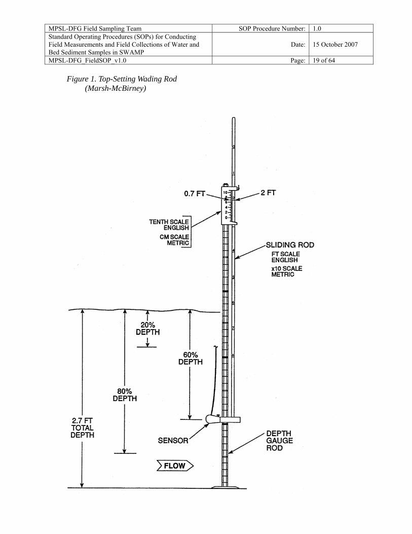
Additional Equipment < Top-setting wading rod (preferably measured in tenths of feet)(see Figure 1). < Tape measure (with gradations every tenth of a foot).
Flow Measurement Procedure (USGS, 1969) Select a stream reach with the following characteristics:
< Straight reach with laminar flow (threads of velocity parallel to each other) and bank to bank. These conditions are typically found immediately upstream of riffle areas or places where the stream channel is constricted.
< The site should have an even streambed free of large rocks, weeds, and protruding obstructions that create turbulence. The site should not have dead water areas near the banks, and a minimum amount of turbulence or back eddies.
Flat Streambed Profile (cross section) Stretch the measuring tape across the stream at right angles to the direction of flow. When using an electronic flow meter, the tape does not have to be exactly perpendicular to the bank (direction of flow). When using a propeller or pigmy type meter, however, corrections for deviation from perpendicular must be made. If necessary and possible, modify the measuring cross section to provide acceptable conditions by building dikes to cut off dead water and shallow flows, remove rocks, weeds, and debris in the reach of stream one or two meters upstream from the measurement cross section. After modifying a streambed, allow the flow to stabilize before starting the flow measurement. Record the following information on the flow measurement form (see example Flow Measurement Forms at end of this document):
< Station Location and Station ID < Date < Time measurement is initiated and ended < Name of person(s) measuring flow < Note if measurements are in feet or meters < Total stream width and width of each measurement section < For each cross section, record the mid-point, section depth and flow velocity
MPSL-DFG Field Sampling Team SOP Procedure Number: 1.0 Standard Operating Procedures (SOPs) for Conducting Field Measurements and Field Collections of Water and Bed Sediment Samples in SWAMP
Date: 15 October 2007
MPSL-DFG_FieldSOP_v1.0 Page: 18 of 64 Measuring the Stream Width Measure and record the stream width between the points where the tape is stretched (waters edge to waters edge). Determining the Number of Flow Cross Sections Determine the spacing and location of flow measurement sections. Some judgment is required depending on the shape of the stream bed. Measurements must be representative of the velocity within the cross-section. If the stream banks are straight and the depth is nearly constant and the bottom is free of large obstructions, fewer measurements are needed, because the flow is homogeneous over a large section. Flow measurement sections do not have to be equal width. However, they should be unless an obstacle or other obstruction prevents an accurate velocity measurement at that point. No flow measurement section should have greater than 10% of the total flow. If the stream width is less than 5 ft, use flow sections with a width of 0.5 ft (See example 1 on page 23 of this document). If the stream width is greater than 5 ft, the minimum number of flow measurements is 10. The preferred number of flow measurement cross sections is 20-30 (See Example 2 on page 24 on this document). The total stream width is 26 ft with 20 measurements, section widths will be 1.3 ft (26/20 = 1.3). Determining the Mid-Point of the Cross Section To find the mid-point of a cross section, divide the cross section width in half. Using Example 2 (see forms at end of document); < The total stream width is 26 ft with 20 cross sections and each cross section width is equal
to 1.3 ft. < Divide 1.3 ft in half and the mid-point of the first section is 0.65 ft. In this example the tape
at waters edge is set at zero (0) ft. < By adding 0.65 to zero the mid-point of the first section is 0.65 ft. < Each subsequent mid-point is found by adding the section width (1.3 ft) to the previous
mid-point. For example; MIDPOINT #1 is 0.65 + 0.0 = 0.65; MIDPOINT #2 is 0.65 + 1.3= 1.95 ft; MIDPOINT #3 is 1.95 + 1.3 = 3.25 ft and ....MIDPOINT # 20 is 24.05 +1.3.
< Place the top setting wading rod at 0.65 ft for the first measurement. < Using a top setting wading rod, measure the depth at the mid-point of the first flow
measurement section and record to the nearest 0.01 ft.
MPSL-DFG Field Sampling Team SOP Procedure Number: 1.0 Standard Operating Procedures (SOPs) for Conducting Field Measurements and Field Collections of Water and Bed Sediment Samples in SWAMP
Date: 15 October 2007
MPSL-DFG_FieldSOP_v1.0 Page: 19 of 64
Figure 1. Top-Setting Wading Rod (Marsh-McBirney)
MPSL-DFG Field Sampling Team SOP Procedure Number: 1.0 Standard Operating Procedures (SOPs) for Conducting Field Measurements and Field Collections of Water and Bed Sediment Samples in SWAMP
Date: 15 October 2007
MPSL-DFG_FieldSOP_v1.0 Page: 20 of 64 Adjusting the Sensor Depth at a Cross Section
Adjust the position of the sensor to the correct depth at each mid-point. The purpose of the top setting wading rod is to allow the user to easily set the sensor at 20%, 60%, and 80% of the total depth. The total depth can be measured with the depth gage rod. Each single mark represents 0.10 foot, each double mark represents 0.50 foot, and each triple mark represents 1.00 foot (see Figure 2).
For Depths < 2.5 Ft
If the depth is less than 2.5 ft, only one measurement is required at each measurement section. To set the sensor at 60% of the depth, line up the foot scale on the sliding rod with the tenth scale, located on top of the depth gage rod. If, for example, the total depth is 2.7 ft (as shown on Figure 2), then line up the 2 on the foot scale with the 7 on the tenth scale (Marsh-McBirney 1990).
For Depths > 2.5 Ft
If the depth is greater than 2.5 ft, two measurements should be taken at 20% and 80% of the total depth. To set the sensor at 20% of the depth, multiply the total depth by two. For example, if the total depth is 2.7 ft, the rod would be set at 5.4 ft (2.7 x 2). Line up the 5 on the sliding rod with the 4 on the tenth scale.
For Depths > 2.5 Ft (cont)
To set the sensor at 80% of the depth, divide the total depth by two. For example, the total depth is 2.7 ft the rod would be set at 1.35 ft (2.7/2). Line up the 1 on the sliding rod with the 0.35 on the tenth scale. The average of the two velocity measurements is used in the flow calculation. See page 2-36 for an example of a flow form recording measurements for depths greater than 2.5 ft.
NOTE: The point where the rod is set for 20 and 80% of the depth will not equal values derived by calculating 20 and 80% of the total depth.
Measuring Velocity (this has typically been measured at 6/10 of the total depth, for velocity-only measurements)
< Position the meter at the correct depth and place at the mid-point of the flow measurement section. Measure and record the velocity and depth. The wading rod is kept vertical and the flow sensor kept perpendicular to the tape rather than perpendicular to the flow while measuring velocity with an electronic flow meter. When using a propeller or pigmy-type meter, however, the instrument should be perpendicular to the flow.
< Permit the meter to adjust to the current for a few seconds. Measure the velocity for a minimum of 20 s with the Marsh-McBirney and Montedoro-Whitney meters. Measure velocity for a minimum of 40 s (preferably 2 min with the Price and pigmy meters).
< When measuring the flow by wading, stand in the position that least affects the velocity
of the water passing the current meter. The person wading stands a minimum of 1.5 ft downstream and off to the side of the flow sensor.
MPSL-DFG Field Sampling Team SOP Procedure Number: 1.0 Standard Operating Procedures (SOPs) for Conducting Field Measurements and Field Collections of Water and Bed Sediment Samples in SWAMP
Date: 15 October 2007
MPSL-DFG_FieldSOP_v1.0 Page: 21 of 64
< A flow sensor, equipped with cable and weight may be used to measure flows where the water is too deep to wade. Follow the procedure involving meters attached to wading rods.
< Report flow values less than 10 ft2 /s to two significant figures. Report flow values greater than 10 ft3/s to the nearest whole number, but no more than three significant figures.
< In cases where the flow is low and falling over an obstruction, it may be possible to measure the flow by timing how long it takes to fill a bucket of known volume.
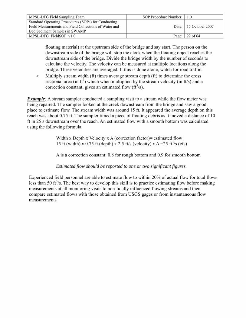
Avoid measuring flow in areas with back eddies. The first choice would be to select a site with no back eddy development. However, this can not be avoided in certain situations. Measure the negative flows in the areas with back eddies. These negative values will be included in the final flow calculation. Calculating Flow To calculate flow, multiply the width x depth (ft2) to derive the area of the flow measurement section. The area of the section is then multiplied by the velocity (ft/s) to calculate the flow in cubic feet per second (cfs or ft3/sec) for that flow measurement section. When flow is calculated for all of the measurement sections, they are added together for the total stream flow (see Figure 2). Q=Total Flow (or discharge), W=Width, D=Depth, V=Velocity. Q = (W1 * D1 * V1) + (W2 *D2* V2) + ...... (Wn*Dn*Vn) What to Do with Negative Values Do not treat cross sections with negative flow values as zero. Negative values obtained from areas with back eddies should be subtracted during the summation of the flow for a site. Flow Estimate (ft3/s) Flow estimate data may be recorded for a non-tidally influenced stream when it is not possible to measure flows by one of the methods described above. Flow estimates are subjective measures based on field personnel's experience and ability to estimate distances, depths, and velocities. If flow can not be measured at a routine non-tidal station, a new site should be selected where flow can be measured. Flow Estimate Procedure
< Observe the stream and choose a reach of the stream where it is possible to estimate the stream cross section and velocity.
< Estimate stream width (ft) at that reach and record. < Estimate average stream depth (ft) at that reach and record. Estimate stream velocity
(ft/s) at that reach and record. A good way to do this is to time the travel of a piece of floating debris. If doing this method from a bridge, measure the width of the bridge. Have one person drop a floating object (something that can be distinguished from other
MPSL-DFG Field Sampling Team SOP Procedure Number: 1.0 Standard Operating Procedures (SOPs) for Conducting Field Measurements and Field Collections of Water and Bed Sediment Samples in SWAMP
Date: 15 October 2007
MPSL-DFG_FieldSOP_v1.0 Page: 22 of 64
floating material) at the upstream side of the bridge and say start. The person on the downstream side of the bridge will stop the clock when the floating object reaches the downstream side of the bridge. Divide the bridge width by the number of seconds to calculate the velocity. The velocity can be measured at multiple locations along the bridge. These velocities are averaged. If this is done alone, watch for road traffic.
< Multiply stream width (ft) times average stream depth (ft) to determine the cross sectional area (in ft2) which when multiplied by the stream velocity (in ft/s) and a correction constant, gives an estimated flow (ft3/s).
Example: A stream sampler conducted a sampling visit to a stream while the flow meter was being repaired. The sampler looked at the creek downstream from the bridge and saw a good place to estimate flow. The stream width was around 15 ft. It appeared the average depth on this reach was about 0.75 ft. The sampler timed a piece of floating debris as it moved a distance of 10 ft in 25 s downstream over the reach. An estimated flow with a smooth bottom was calculated using the following formula.
Width x Depth x Velocity x A (correction factor)= estimated flow 15 ft (width) x 0.75 ft (depth) x 2.5 ft/s (velocity) x A =25 ft3/s (cfs)
A is a correction constant: 0.8 for rough bottom and 0.9 for smooth bottom
Estimated flow should be reported to one or two significant figures.
Experienced field personnel are able to estimate flow to within 20% of actual flow for total flows less than 50 ft3/s. The best way to develop this skill is to practice estimating flow before making measurements at all monitoring visits to non-tidally influenced flowing streams and then compare estimated flows with those obtained from USGS gages or from instantaneous flow measurements
MPSL-DFG Field Sampling Team SOP Procedure Number: 1.0 Standard Operating Procedures (SOPs) for Conducting Field Measurements and Field Collections of Water and Date: 15 October 2007 Bed Sediment Samples in SWAMP MPSL-DFG_FieldSOP_v1.0 Page: 23 of 64
Figure 2. Stream Flow (Discharge) Measurement
MPSL-DFG Field Sampling Team SOP Procedure Number: 1.0 Standard Operating Procedures (SOPs) for Conducting Field Measurements and Field Collections of Water and Bed Sediment Samples in SWAMP
Date: 15 October 2007
MPSL-DFG_FieldSOP_v1.0 Page: 24 of 64
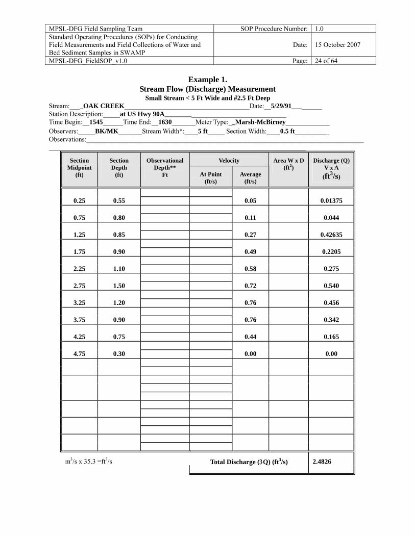
Example 1. Stream Flow (Discharge) Measurement
Small Stream < 5 Ft Wide and #2.5 Ft Deep Stream:____OAK CREEK_____________________________________Date:__5/29/91_________ Station Description:_____at US Hwy 90A____________________________________ Time Begin:__1545______Time End:__1630_______Meter Type:__Marsh-McBirney_____________ Observers:_____BK/MK_______Stream Width*:____5 ft_____ Section Width:____0.5 ft__________ Observations:______________________________________________________________________________________________________________________________________________________________
Velocity
Section
Midpoint (ft)
Section Depth
(ft)
Observational
Depth** Ft
At Point
(ft/s)
Average
(ft/s)
Area W x D
(ft2)
Discharge (Q)
V x A (ft3/s)
0.25
0.55
0.05
0.01375
0.75
0.80
0.11
0.044
1.25
0.85
0.27
0.42635
1.75
0.90
0.49
0.2205
2.25
1.10
0.58
0.275
2.75
1.50
0.72
0.540
3.25
1.20
0.76
0.456
3.75
0.90
0.76
0.342
4.25
0.75
0.44
0.165
4.75
0.30
0.00
0.00
2.4826
m3/s x 35.3 =ft3/s
Total Discharge (3Q) (ft3/s)
MPSL-DFG Field Sampling Team SOP Procedure Number: 1.0 Standard Operating Procedures (SOPs) for Conducting Field Measurements and Field Collections of Water and Bed Sediment Samples in SWAMP
Date: 15 October 2007
MPSL-DFG_FieldSOP_v1.0 Page: 25 of 64
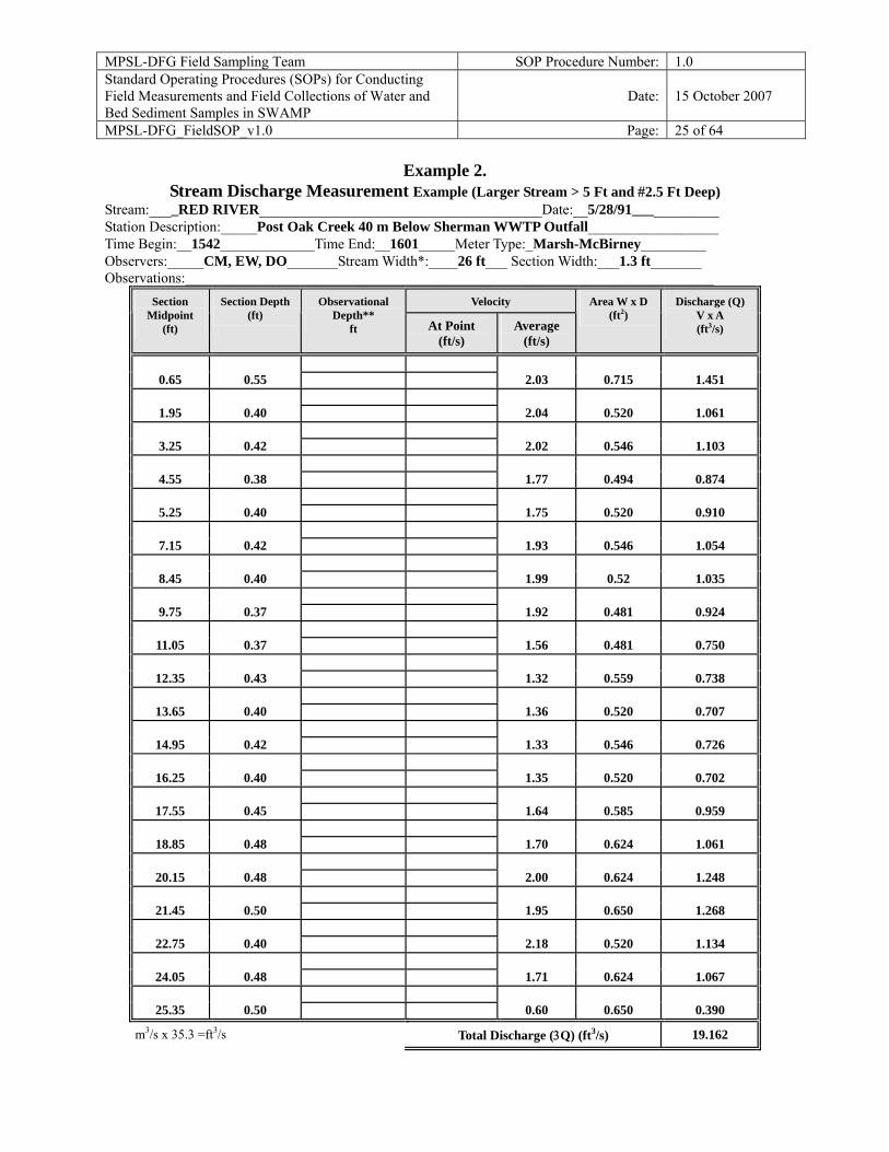
Example 2. Stream Discharge Measurement Example (Larger Stream > 5 Ft and #2.5 Ft Deep)
Stream:____RED RIVER_______________________________________Date:__5/28/91____________ Station Description:_____Post Oak Creek 40 m Below Sherman WWTP Outfall__________________ Time Begin:__1542_____________Time End:__1601_____Meter Type:_Marsh-McBirney_________ Observers:_____CM, EW, DO_______Stream Width*:____26 ft___ Section Width:___1.3 ft_______ Observations:_________________________________________________________________________
Veloci y t
Section
Midpoint (ft)
Section Depth
(ft)
Observational
Depth** ft
At Point
(ft/s)
Average
(ft/s)
Area W x D
(ft2)
Discharge (Q)
V x A (ft3/s)
0.65
0.55
2.03
0.715
1.451
1.95
0.40
2.04
0.520
1.061
3.25
0.42
2.02
0.546
1.103
4.55
0.38
1.77
0.494
0.874
5.25
0.40
1.75
0.520
0.910
7.15
0.42
1.93
0.546
1.054
8.45
0.40
1.99
0.52
1.035
9.75
0.37
1.92
0.481
0.924
11.05
0.37
1.56
0.481
0.750
12.35
0.43
1.32
0.559
0.738
13.65
0.40
1.36
0.520
0.707
14.95
0.42
1.33
0.546
0.726
16.25
0.40
1.35
0.520
0.702
17.55
0.45
1.64
0.585
0.959
18.85
0.48
1.70
0.624
1.061
20.15
0.48
2.00
0.624
1.248
21.45
0.50
1.95
0.650
1.268
22.75
0.40
2.18
0.520
1.134
24.05
0.48
1.71
0.624
1.067
25.35
0.50
0.60
0.650
0.390
m3/s x 35.3 =ft3/s
Total Discharge (3Q) (ft3/s)
19.162
MPSL-DFG Field Sampling Team SOP Procedure Number: 1.0 Standard Operating Procedures (SOPs) for Conducting Field Measurements and Field Collections of Water and Bed Sediment Samples in SWAMP
Date: 15 October 2007
MPSL-DFG_FieldSOP_v1.0 Page: 26 of 64
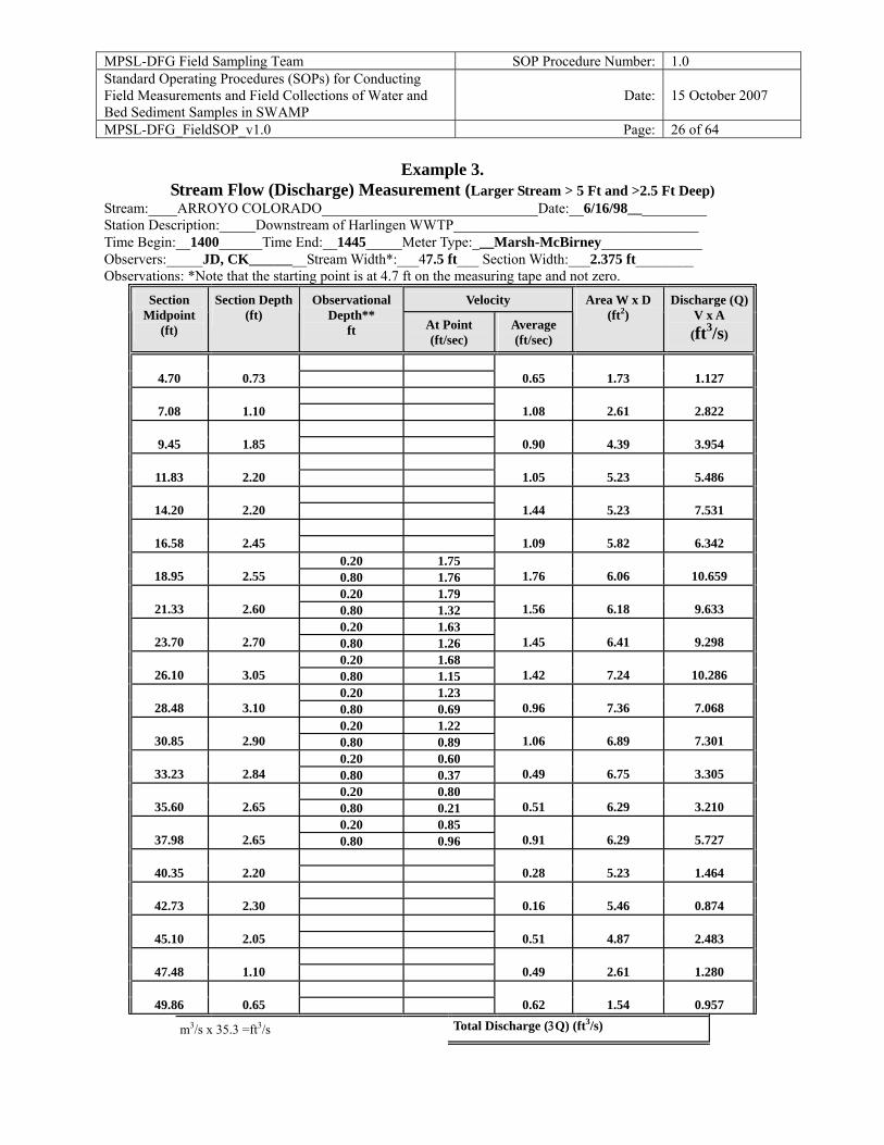
Example 3. Stream Flow (Discharge) Measurement (Larger Stream > 5 Ft and >2.5 Ft Deep)
Stream:____ARROYO COLORADO______________________________Date:__6/16/98___________ Station Description:_____Downstream of Harlingen WWTP__________________________________ Time Begin:__1400______Time End:__1445_____Meter Type:___Marsh-McBirney______________ Observers:_____JD, CK________Stream Width*:___47.5 ft___ Section Width:___2.375 ft________ Observations: *Note that the starting point is at 4.7 ft on the measuring tape and not zero.
Velocity
Section
Midpoint (ft)
Section Depth
(ft)
Observational
Depth** ft
At Point (ft/sec)
Average (ft/sec)
Area W x D
(ft2)
Discharge (Q)
V x A (ft3/s)
4.70
0.73
0.65
1.73
1.127
7.08
1.10
1.08
2.61
2.822
9.45
1.85
0.90
4.39
3.954
11.83
2.20
1.05
5.23
5.486
14.20
2.20
1.44
5.23
7.531
16.58
2.45
1.09
5.82
6.342
0.20 1.75 18.95
2.55 0.80 1.76
1.76
6.06
10.659
0.20 1.79 21.33
2.60 0.80 1.32
1.56
6.18
9.633
0.20 1.63 23.70
2.70 0.80 1.26
1.45
6.41
9.298
0.20 1.68 26.10
3.05 0.80 1.15
1.42
7.24
10.286
0.20 1.23 28.48
3.10 0.80 0.69
0.96
7.36
7.068
0.20 1.22 30.85
2.90 0.80 0.89
1.06
6.89
7.301
0.20 0.60 33.23
2.84 0.80 0.37
0.49
6.75
3.305
0.20 0.80 35.60
2.65 0.80 0.21
0.51
6.29
3.210
0.20 0.85 37.98
2.65 0.80 0.96
0.91
6.29
5.727
40.35
2.20
0.28
5.23
1.464
42.73
2.30
0.16
5.46
0.874
45.10
2.05
0.51
4.87
2.483
47.48
1.10
0.49
2.61
1.280
49.86
0.65
0.62
1.54
0.957
m3/s x 35.3 =ft3/s Total Discharge (3Q) (ft3/s)
MPSL-DFG Field Sampling Team SOP Procedure Number: 1.0 Standard Operating Procedures (SOPs) for Conducting Field Measurements and Field Collections of Water and Bed Sediment Samples in SWAMP
Date: 15 October 2007
MPSL-DFG_FieldSOP_v1.0 Page: 27 of 64
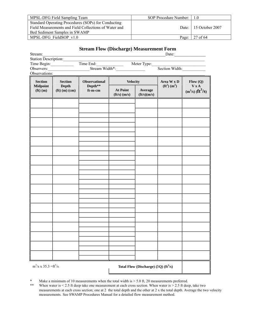
Stream Flow (Discharge) Measurement Form Stream:___________________________________________________________Date:_______________ Station Description:____________________________________________________________________ Time Begin:___________ Time End:_____________ Meter Type:__________________________ Observers:____________________ Stream Width*:______________ Section Width:___________ Observations:_________________________________________________________________________
Velocity
Section
Midpoint (ft) (m)
Section Depth
(ft) (m) (cm)
Observational
Depth** ft-m-cm
At Point
(ft/s) (m/s)
Average
(ft/s)(m/s)
Area W x D
(ft2) (m2)
Flow (Q)
V x A (m3/s) (ft3/s)
m3/s x 35.3 =ft3/s
Total Flow (Discharge) (3Q) (ft3/s)
* Make a minimum of 10 measurements when the total width is > 5.0 ft, 20 measurements preferred. ** When water is < 2.5 ft deep take one measurement at each cross section. When water is > 2.5 ft deep, take two
measurements at each cross section; one at 2 the total depth and the other at 2 x the total depth. Average the two velocity measurements. See SWAMP Procedures Manual for a detailed flow measurement method.
MPSL-DFG Field Sampling Team SOP Procedure Number: 1.0 Standard Operating Procedures (SOPs) for Conducting Field Measurements and Field Collections of Water and Bed Sediment Samples in SWAMP
Date: 15 October 2007
MPSL-DFG_FieldSOP_v1.0 Page: 28 of 64
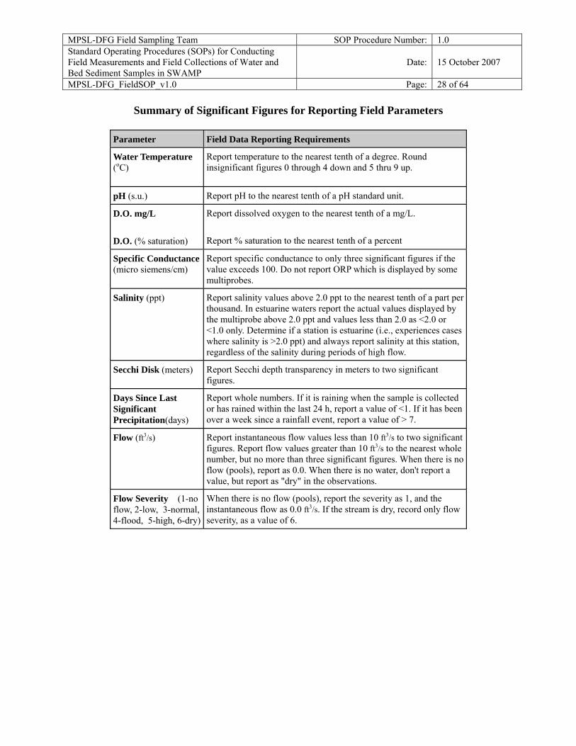
Summary of Significant Figures for Reporting Field Parameters
Parameter Field Data Reporting Requirements
Water Temperature (oC)
Report temperature to the nearest tenth of a degree. Round insignificant figures 0 through 4 down and 5 thru 9 up.
pH (s.u.)
Report pH to the nearest tenth of a pH standard unit.
D.O. mg/L D.O. (% saturation)
Report dissolved oxygen to the nearest tenth of a mg/L. Report % saturation to the nearest tenth of a percent
Specific Conductance (micro siemens/cm)
Report specific conductance to only three significant figures if the value exceeds 100. Do not report ORP which is displayed by some multiprobes.
Salinity (ppt)
Report salinity values above 2.0 ppt to the nearest tenth of a part per thousand. In estuarine waters report the actual values displayed by the multiprobe above 2.0 ppt and values less than 2.0 as <2.0 or <1.0 only. Determine if a station is estuarine (i.e., experiences cases where salinity is >2.0 ppt) and always report salinity at this station, regardless of the salinity during periods of high flow.
Secchi Disk (meters)
Report Secchi depth transparency in meters to two significant figures.
Days Since Last Significant Precipitation(days)
Report whole numbers. If it is raining when the sample is collected or has rained within the last 24 h, report a value of <1. If it has been over a week since a rainfall event, report a value of > 7.
Flow (ft3/s)
Report instantaneous flow values less than 10 ft3/s to two significant figures. Report flow values greater than 10 ft3/s to the nearest whole number, but no more than three significant figures. When there is no flow (pools), report as 0.0. When there is no water, don't report a value, but report as "dry" in the observations.
Flow Severity (1-no flow, 2-low, 3-normal, 4-flood, 5-high, 6-dry)
When there is no flow (pools), report the severity as 1, and the instantaneous flow as 0.0 ft3/s. If the stream is dry, record only flow severity, as a value of 6.
MPSL-DFG Field Sampling Team SOP Procedure Number: 1.0 Standard Operating Procedures (SOPs) for Conducting Field Measurements and Field Collections of Water and Bed Sediment Samples in SWAMP
Date: 15 October 2007
MPSL-DFG_FieldSOP_v1.0 Page: 29 of 64
BEAUFORT SCALE: Specifications and equivalent speeds for use at sea FORCE EQUIVALEN SPEED DESCRIPTION SPECIFICATIONS FOR USE AT SEA 10 m above ground Miles/hour knots 0 0-1 0-1 Calm Sea like a mirror 1 1-3 1-3 Light air Ripples with the appearance of scales are formed, but without foam crests. 2 4-7 4-6 Light Breeze Small wavelets, still short, but more pronounced. Crests have a glassy appearance and do not break. 3 8-12 7-10 Gentle Breeze Large wavelets. Crests begin to break. Foam of glassy appearance. Perhaps scattered white horses. 4 13-18 11-16 Moderate Breeze Small waves, becoming larger; fairly frequent white horses. 5 19-24 17-21 Fresh Breeze Moderate waves, taking a more pronounced long form; many white horses are formed. Chance of some spray. 6 25-31 22-27 Strong Breeze Large waves begin to form; the white foam crestsare more extensive everywhere. Probably some spray. 7 32-38 28-33 Near Gale Sea heaps up and white foam from breaking waves begins to be blown in streaks along the direction of the wind. 8 39-46 34-40 Gale Moderately high waves of greater length; edges of crests begin to break into spindrift. The foam is blown in well-marked streaks along the direction of the wind. 9 47-54 41-47 Severe Gale High waves. Dense streaks of foam along the direction of the wind. Crests of waves begin to topple, tumble, and roll over. Spray may affect visibility. 10 55-63 48-55 Storm Very high waves with long over- hanging crests. he resulting foam, in great patches, is blown in dense white streaks along the direction of the wind. On he whole the surface of the sea takes on a white appearance. The 'tumbling' of the sea becomes heavy and shock-like. Visibility affected. Last edited on 09 January, 1999 Dave Wheeler [email protected] Web Space kindly provided by Zetnet Services Ltd, Lerwick, Shetland. http://www.zetnet.co.uk/sigs/weather/Met_Codes/beaufort.htm
MPSL-DFG Field Sampling Team SOP Procedure Number: 1.0 Standard Operating Procedures (SOPs) for Conducting Field Measurements and Field Collections of Water and Bed Sediment Samples in SWAMP
Date: 15 October 2007
MPSL-DFG_FieldSOP_v1.0 Page: 30 of 64
Field Collection Procedures for Water Samples Scope and Application This protocol describes the techniques used to collect water samples in the field in a way that neither contaminates, loses, or changes the chemical form of the analytes of interest. The samples are collected in the field into previously cleaned and tested (if necessary) sample bottles of a material appropriate to the analysis to be conducted. Pre-cleaned sampling equipment is used for each site, whenever possible and/or when necessary. Appropriate sampling technique and measuring equipment may vary depending on the location, sample type, sampling objective, and weather. Trade names used in connection with equipment or supplies do not constitute an endorsement of the product.
Summary of Method Appropriate sample containers and field measurement gear as well as sampling gear are transported to the site where samples are collected according to each sample’s protocol. Water velocity, turbidity, temperature, pH, conductivity, dissolved oxygen as well as other field data are measured and recorded using the appropriate equipment. These field data measurement protocols are provided in the SWAMP Field Measurement SOP. Samples are put on ice and appropriately shipped to the processing laboratories. This procedure has been modified from the Texas Natural Resources Conservation Commission’s Procedure Manual for Surface Water Quality Monitoring, with major input from the United State’s Geological Survey’s (USGS’s) National Water Quality Assessment (NAWQA) Protocol for Collection of Stream Water Samples, for which due credit is herewith given.
WATER SAMPLE COLLECTION Water chemistry and bacteriological samples, as requested, are collected at the same location. Water samples are best collected before any other work is done at the site. If other work (e.g., sediment sample collection, flow measurement or biological/habitat sample collection or assessment) is done after or downstream of the collection of water samples, it might be difficult to collect representative samples for water chemistry and bacteriology from the disturbed stream. Care must be taken, though, to not disturb sediment collection sites when taking water samples. The following general information applies to all types of water samples, unless noted otherwise:
Sample Collection Depth
Sub-Surface Grab Sample Samples are collected at 0.1 m below the water surface. Containers should be opened and re-capped under water in most cases. Depth-integrated Sample If a depth-integrated sample is
MPSL-DFG Field Sampling Team SOP Procedure Number: 1.0 Standard Operating Procedures (SOPs) for Conducting Field Measurements and Field Collections of Water and Bed Sediment Samples in SWAMP
Date: 15 October 2007
MPSL-DFG_FieldSOP_v1.0 Page: 31 of 64
taken, the sample is pumped from discrete intervals within the entire water column. Surface Grab Sample Samples are collected at the surface when water depth is <0.1 m. Since there is a difference in water chemistry on the surface, compared to subsurface, surface water should be noted on the field data sheet as 0 m.
Where to Collect Samples
Water samples are collected from a location in the stream where the stream visually appears to be completely mixed. Ideally this would be at the centroid of the flow (Centroid is defined as the midpoint of that portion of the stream width, which contains 50% of the total flow), but depth and flow do not always allow centroid collection. For stream samples, the sampling spot must be accessible for sampling physicochemical parameters, either by bridge, boat or wading. Sampling from the shoreline of any water body (meaning standing on shore and sampling from there) is the least acceptable method, but in some cases is necessary. In reservoirs, lakes, rivers, and coastal bays, samples are collected from boats at designated locations provided by Regional Water Quality Control Boards (Regional Boards).
Sampling Order if Multiple Media are Requested to be Collected
The order of events at every site has to be carefully planned. For example, if sediment is to be collected, the substrate can not be disturbed by stepping over or on it; water samples can not be taken where disturbed sediment would lead to a higher content of suspended matter in the sample. For the most part, water samples are best collected before any other work is done at the site. This information pertains to walk-in sampling.
Sample Container Labels
Label each container with the station ID, sample code, matrix type, analysis type, project ID, and date and time of collection (in most cases, containers will be pre-labeled). After sampling, secure the label by taping around the bottle with clear packaging tape.
Procedural Notes For inorganic and organic water samples, bottles do not have to be rinsed if they are I-Chem 200 series or higher or ESS PC grade or higher. This means that the sample bottles are analyzed for contamination, and a certification of analysis is included with the bottles. Other sample containers are usually rinsed at least three times if the bottles do not meet these
MPSL-DFG Field Sampling Team SOP Procedure Number: 1.0 Standard Operating Procedures (SOPs) for Conducting Field Measurements and Field Collections of Water and Bed Sediment Samples in SWAMP
Date: 15 October 2007
MPSL-DFG_FieldSOP_v1.0 Page: 32 of 64
requirements. See filling instruction for each type of analyses if there is uncertainty. If applicable to the sample and analysis type, the sample container should be opened and re-capped under water.
Sample Short-term Storage and Preservation
Properly store and preserve samples as soon as possible. Usually this is done immediately after returning from the collection by placing the containers on bagged, crushed or cube ice in an ice chest. Sufficient ice will be needed to lower the sample temperature to at least 4 °C within 45 min after time of collection. Sample temperature will be maintained at 4 °C until delivered to the laboratory. Care is taken at all times during sample collection, handling and transport to prevent exposure of the sample to direct sunlight. Samples are preserved in the laboratory, if necessary, according to protocol for specific analysis (acidification in most cases).
Field Safety Issues Proper gloves must be worn to prevent contamination of the sample and to protect the sampler from environmental hazards (disposable polyethylene, nitrile, or non-talc latex gloves are recommended, however, metals and mercury sample containers can only be sampled and handled using polyethylene gloves as the outer layer). Wear at least one layer of gloves, but two layers help protect against leaks. One layer of shoulder high gloves worn as a first (inside) layer is recommended to have the best protection for the sampler. Safety precautions are needed when collecting samples, especially samples that are suspected to contain hazardous substances, bacteria, or viruses.
Sample Handling and Shipping
Due to increased shipping restrictions, samples being sent via a freight carrier require additional packing. Although care is taken in sealing the ice chest, leaks can and do occur. Samples and ice should be bagged placed inside a large trash bag inside the ice chest for shipping. Ice should be double bagged to prevent melted ice water from leaking into the sample. The large trash bag can be sealed by simply twisting the bag closed (while removing excess air) and taping the tail down. Prior to shipping the drain plug of the ice chests have to be taped shut. Leaking ice chests can cause samples to be returned or arrive at the lab beyond the holding time. Although glass containers are acceptable for sample collection, bubble wrap must be used when shipping glass.
MPSL-DFG Field Sampling Team SOP Procedure Number: 1.0 Standard Operating Procedures (SOPs) for Conducting Field Measurements and Field Collections of Water and Bed Sediment Samples in SWAMP
Date: 15 October 2007
MPSL-DFG_FieldSOP_v1.0 Page: 33 of 64
Chain of Custody (COC) Forms
Every shipment must contain a complete Chain of Custody (COC) Form that lists all samples collected and the analyses to be performed on these samples. Make sure a COC is included for every laboratory, every time you send a shipment of samples. Electronic COCs can also be emailed to the various laboratories but must be sent before the samples arrive at their destinations. Include region and trip information as well as any special instructions to the laboratory on the COC. The original COC sheet (not the copies) is included with the shipment (insert into ziplock bag) One copy goes to the sampling coordinator, and the sampling crew keeps one copy. Samples collected should have the salinity (in ppt), depth of collection, and date/time collected for each station on every COC. Write a comment on this form, if you want to warn the laboratory personnel about possibly hazardous samples that contain high bacteria, chlorine or organic levels.
Field QC Samples for Water Analyses
Field duplicates are currently submitted at an annual rate of 5%. Field travel blanks are required for volatile organic compounds at a rate of one per cooler shipped. Field blanks are required for trace metals (including mercury and methyl mercury), DOC, and volatile organic compounds in water at a rate of 5%. See Appendix C of the SWAMP QAMP for detailed Field QC requirements.
Field Site Data Sheets Each visited field site requires a field observation completed SWAMP Field Data Sheet, even if no samples are collected (i.e. at a site which is found to be dry). If water and/or sediment samples are collected, all elements of the SWAMP Field Data Sheet must be completely filled out.
General Pre-Sampling Procedures
Instruments. All instruments must be in proper working condition. Make sure all calibrations are current. Multi-probe sondes should be pre-calibrated every morning prior to sampling and post-calibrated within 24 h of the original calibration. Conductivity should also be calibrated between stations if there is a significant change in salinity. Dissolved oxygen sensors should be re-calibrated if there is a 500 ft
MPSL-DFG Field Sampling Team SOP Procedure Number: 1.0 Standard Operating Procedures (SOPs) for Conducting Field Measurements and Field Collections of Water and Bed Sediment Samples in SWAMP
Date: 15 October 2007
MPSL-DFG_FieldSOP_v1.0 Page: 34 of 64
change in elevation. Calibration Standards. Pack all needed calibration standards. Sample Storage Preparations. A sufficient amount of cube ice, blue ice and dry ice as well as enough coolers of the appropriate type/size must be brought into the field, or sources for purchasing these supplies identified in advance. Sample Container Preparation. After arriving at the sample station, pack all needed sample containers for carriage to the actual collection site, and label them with a pre-printed label containing Station ID, Sample Code, Matrix info, Analysis Type info, Project ID and blank fields for date and time (if not already pre-labeled). Safety Gear. Pack all necessary safety gear like waders, protective gloves and safety vests. Walk to the site. For longer hikes to reach a sample collection site, large hiking backpacks are recommended for transport of gear, instruments and containers. Tote bins can be used, if the sampling site can be accessed reasonably close to the vehicle. GPS. At the sampling site, compare/record reconnaissance GPS reading with current site reading and note differences. GPS coordinates should be in Decimal Degrees (e.g. 38.12345 -117.12345).
COLLECTION OF WATER SAMPLES FOR ANALYSIS OF CONVENTIONAL CONSTITUENTS In most streams, sub-surface (0.1 m below surface) water is representative of the water mass. A water sample for analysis of conventional constituents is collected by the grab method in most cases, immersing the container beneath the water surface to a depth of 0.1 m. Sites accessed by bridge can be sampled with a sample container-suspending device. Extreme care must be taken to avoid contaminating the sample with debris from the rope and bridge. Care must also be taken to rinse the device between stations. If the centroid of the stream cannot be sampled by wading, sampling devices can be attached to an extendable sampling pole.
MPSL-DFG Field Sampling Team SOP Procedure Number: 1.0 Standard Operating Procedures (SOPs) for Conducting Field Measurements and Field Collections of Water and Bed Sediment Samples in SWAMP
Date: 15 October 2007
MPSL-DFG_FieldSOP_v1.0 Page: 35 of 64
In some cases, depth-integrated sampling is required, as requested by Regional Boards. This is useful when lakes or rivers are stratified and a sample is wanted that represents the entire water column. Depth-integrated sample collection is explained later in this document.
Conventional Water Constituents, Routinely Requested in SWAMP
Chloride, sulfate, nitrite, nitrate (or nitrate+nitrate), ortho-phosphate, fluoride, total phosphorus, ammonia, TKN, alkalinity, chlorophyll a.
Conventional Water Constituents, Occasionally Requested in SWAMP
Total Suspended Solids (TSS) or Suspended Sediment Concentration (SSC), Total Dissolved Solids (TDS--especially if total metals requested), Total Organic Carbon (TOC), Dissolved Organic Carbon (DOC), hardness (if trace metals analysis is requested).
Conventional Water Constituents Sample Volume
Due to the potential for vastly different arrays of requested analyses for conventional constituents, please refer to table at the end of this document, as well as the Sample Handling Requirements Tables in Appendix C of the QAMP, for information on the proper volume to collect for the various types of analyses.
Conventional Water Constituents Sample Container Type
Due to the potential for vastly different arrays of requested analyses for conventional constituents, please refer to table at the end of this document, as well as the Sample Handling Requirements Tables in Appendix C of the QAMP, for information on the proper type of sample containers.
Chlorophyll a Syringe Sample Method
Chlorophyll a syringe method: Chlorophyll a is sampled by forcing water with a 60-mL syringe through a filter holder containing a 25-mm glass microfiber filter. The 60-mL syringe and an in-line filter holder are rinsed three times with the ambient water before filtration. The syringe is then filled with 60 mL of ambient water. The filter holder is then removed and a 25-mm glass microfiber filter is placed inside. The filter holder is then screwed onto the syringe and the ambient water is then flushed through the filter. The filter holder is removed every time more water needs to be drawn into the syringe. The process is then repeated until the desired amount of Chlorophyll a is present (usually 60 to 360 mL depending on the water clarity). When filtering is complete the filter holder is opened and the filter is removed with tweezers without
MPSL-DFG Field Sampling Team SOP Procedure Number: 1.0 Standard Operating Procedures (SOPs) for Conducting Field Measurements and Field Collections of Water and Bed Sediment Samples in SWAMP
Date: 15 October 2007
MPSL-DFG_FieldSOP_v1.0 Page: 36 of 64
touching the Chlorophyll a. The filter is then folded in half, then again, in half with the Chlorophyll a inside the folds. The folded filter is then wrapped in aluminum foil and placed in an envelope labeled with the site information and the volume filtered. The envelope is then immediately placed on dry ice until transferred to the lab.
MPSL-DFG Field Sampling Team SOP Procedure Number: 1.0 Standard Operating Procedures (SOPs) for Conducting Field Measurements and Field Collections of Water and Bed Sediment Samples in SWAMP
Date: 15 October 2007
MPSL-DFG_FieldSOP_v1.0 Page: 37 of 64
Collection of Water Samples for Analysis of Trace Metals (Including Mercury) When deciding to measure total and dissolved metals in water the purpose of the sampling must be considered. Water quality standards for the protection of aquatic life are determined for the dissolved form of heavy metals in most cases, although this, too, can vary within different Basin Plans for different regions. The exception to routinely conducting dissolved metals analyses is usually mercury (and often selenium). Water quality standards usually apply to the total form of mercury (and often selenium), and not the dissolved form of these elements. Several regions are interested in conducting total metals analyses, in order to address specific issues. In order to budget inputs, transport, and accumulation of metals, it is necessary to know the concentration of total metals in the water column, sediments, effluent, etc. Sample collection for trace metals and mercury in water requires “Clean Hands/Dirty Hands” methodology.
Metals-in-water: General Information
Unless otherwise requested to collect for total metals analysis, dissolved metals are collected for all elements with the exception of mercury. Metals-in-water samples should not be collected during periods of abnormally high turbidity if at all possible. Samples with high turbidity are unstable in terms of soluble metals, and it is difficult to collect a representative grab sample. Special study sampling, however, may be an exception. For example, wet weather sampling is likely to include some samples with high turbidity.
Metals-in-water: Sample Collection Depth
Collect a metals sample from a depth of 0.1 m using a sub -surface grab method, or at discrete depths using a depth-integrated sampling method with a peristaltic pump (described further down). In most streams, sub-surface water is representative of the water mass. For the purpose of determining compliance with numerical toxic substance standards, a sample taken at the surface is adequate.
Metals-in-water: Sample Volume
Refer to table at end of this document, as well as Sample Handling Requirements Tables in Appendix C of the QAMP, for specific information on the proper volume to collect for trace metals analyses. Generally, for procedures most commonly used for analysis of metals in water (total or dissolved metals); one 60-mL polyethylene container is filled with the salinity recorded on the field data sheet and COC. Generally, for the procedures most commonly used for analysis of mercury in water (whether total or dissolved), one 250-mL glass or teflon container is filled, regardless of the salinity. All containers are pre-cleaned in the lab using HNO3.
MPSL-DFG Field Sampling Team SOP Procedure Number: 1.0 Standard Operating Procedures (SOPs) for Conducting Field Measurements and Field Collections of Water and Bed Sediment Samples in SWAMP
Date: 15 October 2007
MPSL-DFG_FieldSOP_v1.0 Page: 38 of 64
Metals-in-water: Sampling Equipment
The method of choice for the collection of water samples for trace metals analysis in small, wadeable streams is the grab method, where the sampler submerges the sample bottle or syringe beneath the surface of the water until filled. The procedure for filtration of water samples for trace metals (including mercury) analysis must be performed within the 48-h maximum holding time (as well as acid preservation), and with extreme care to avoid contamination of the water sample. Considering these factors, it is best to use a field filtration system, such as a set-up with peristaltic pump with in-line filter, or a set-up with a syringe filter, if filtered water is required. Samples are pumped and/or filtered directly into the sample container. This minimizes contamination by using no intermediate sampling device. Samples can also be filtered in lab if need be Un-powdered (no-talc) polyethylene gloves are always worn during sampling for metals-in-water. Depth-integrated sampling is useful when lakes or rivers are stratified and a representative sample is wanted which represents the entire water column. The method involves a peristaltic pump system with enough Teflon tubing to pump at the desired depth with an inline filter. Alternatively, mercury and metal samples can be filtered in the laboratory as long as they are filtered within the 48-hr maximum holding time and filter equipment blanks are analyzed for five percent of all cleaned equipment.
Equipment Preparation
It is best if the metals-in-water sampling materials are prepared by a laboratory that can guarantee contamination-free sampling supplies. If a laboratory assembles a Metals-in-Water Sample Collection Kit, it should contain the following items packaged together for each sample:
• Tubing with an in-line filter (disposable, 0.45 µm) attached for dissolved metals-in-water sampling. This same tubing is used for total metals-in-water samples without filter. If an in-line pumping system is not used, an acid cleaned syringe and filter are packed.
• Sample containers- polyethylene for total and dissolved samples and blanks; Glass or Teflon for total and dissolved mercury.
• Acid preservation is performed in the laboratory. • Metals-free DI water (for blanks).
MPSL-DFG Field Sampling Team SOP Procedure Number: 1.0 Standard Operating Procedures (SOPs) for Conducting Field Measurements and Field Collections of Water and Bed Sediment Samples in SWAMP
Date: 15 October 2007
MPSL-DFG_FieldSOP_v1.0 Page: 39 of 64
• Powder-free polyethylene gloves
If a laboratory is not assembling collection kits, individuals should take care to keep containers in the original packaging. When removed from the box, sample containers are placed in plastic bags (ziplock bags). Although filters come individually wrapped, they should also be stored in new ziplock bags to avoid possible contamination. The filtering equipment is pre-cleaned according to laboratory protocol. Clean tubing is put into clean containers, such as large ziplock bags. Metals-free filter cartridges with the capacity to filter several liters are commercially available. Equipment blanks are run at the laboratory on batches of metals-in-water sampling equipment prior to their distribution to field staff. One to two liter containers with metals-free deionized water are taken into the field for travel blanks. Metals-free deionized water is supplied by the laboratory performing metals analysis. The deionized water containers are kept clean and dust-free on the outside by wrapping in two plastic bags.
Dissolved and Total Metals-in-Water: Detailed Collection Techniques
Sub-Surface Grab Method Syringe Filtration Method (for sub- surface collection) Peristaltic Pumping Method (Using Tubing/In-line Cartridge Filters)for sub- surface
collection or for depth-integrated collection
Metals-in-water Sample Collection: Sub-Surface Grab Method
Unfiltered Samples (for total metals analysis, if requested, and for mercury almost always, unless otherwise requested): Some samples can be sampled directly from the ambient water either by wading into the stream and dipping bottles under the surface of the water until filled, or by sampling from a boat and dipping the bottle under the surface of the water until it is filled. The bottles are cleaned according to laboratory protocol. It is very critical that all the acid is rinsed out of the bottles before the samples are taken. Personnel involved in field sample collection/processing wear polyethylene gloves. The laboratory pre-cleaned glass or Teflon™ 250 mL (for mercury) or polyethylene 60 mL (for
MPSL-DFG Field Sampling Team SOP Procedure Number: 1.0 Standard Operating Procedures (SOPs) for Conducting Field Measurements and Field Collections of Water and Bed Sediment Samples in SWAMP
Date: 15 October 2007
MPSL-DFG_FieldSOP_v1.0 Page: 40 of 64
metals) sample bottles are taken from the double-wrapped plastic bags using “Clean Hands/Dirty Hands” techniques. The dirty hands person opens the first bag, and the clean hands person opens the inner bag around the bottle. The clean hands person then removes the bottle from the inner bag. The clean hands person dips the bottle into the ambient water, with the cap on, to approximately 0.1 m (avoiding disturbing surface scums), placing the cap back on the bottle before being removed from the water, rinses the bottle five times with ambient water, making sure the threads of the bottle get rinsed as well, and fills the bottle to the top. The lid is secured and the bottle is put back into the inner clean bag and sealed by the clean collector. The dirty hands collector then seals the outer bag.
Metals-in-water Sample Collection: Syringe Filtration Method (for sub-surface collection)
Filtered Samples (for dissolved metals analyses): Sub- surface water samples are filtered for dissolved trace metals analysis (not for mercury, however, in almost all cases) using the following syringe filtration method. The syringe (60 cc size, pre-cleaned in the laboratory) and in-line filter are pre-packed in two ziplock bags. The syringe and filter are taken out of the bags using “Clean Hands/Dirty Hands” technique, as previously described. The sub-surface water sample is collected by 1) wading out into the centroid portion of the stream, or by leaning over the edge of the boat, and aspirating water into the syringe, filling and rinsing the syringe five times with ambient water; 2) attaching the filter onto the syringe and filling the syringe body; 3) rinsing the filter with a few milliliters of the sample; 4) rinsing the sample bottle five times with the filtered ambient water; and 5) extruding the sample through the syringe filter and completely filling each bottle. The bottles are taken out of and put back into their bags using “Clean Hands/Dirty Hands”.
Metals-in-water Sample Collection-- Peristaltic Pump
The basic “Clean Hands/Dirty Hands” technique is also applied in the use of a peristaltic pump with an in-line filter cartridge for metals-in-water sample collection. Dirty Hands removes the plastic cover from the end of the pump tubing and inserts the tubing into the sampling container. Dirty Hands holds the tubing in place. The in-line cartridge filter is attached to the outlet end of the tubing. Clean Hands takes the plastic cover off the other end of the tubing. Dirty Hands turns on the pump and flushes l L of ambient water through the tubing to purge it for dissolved
MPSL-DFG Field Sampling Team SOP Procedure Number: 1.0 Standard Operating Procedures (SOPs) for Conducting Field Measurements and Field Collections of Water and Bed Sediment Samples in SWAMP
Date: 15 October 2007
MPSL-DFG_FieldSOP_v1.0 Page: 41 of 64
metals. Clean Hands removes the cap from the sample bottle and uses the pump to fill it with ambient water. Clean Hands puts the cap back on the bottle and places it in the plastic bag.
Metals-in-water Sample Collection: Depth-Integrated Sampling, using In-line Cartridge Filter and Peristaltic Pump
Preparation for Depth-integrated sample collection: Depth-integrated sampling is useful when lakes or rivers are stratified, and a representative sample is wanted that represents the entire water column to the extent possible. The method utilized to date for SWAMP involves a peristaltic pump system with enough Teflon tubing to pump from the desired depth. Regional Boards must request depth-integrated sampling. The tubing set consists of a small length of CFLEX tubing that fits in the peristaltic pump, with an appropriate length of Teflon tubing on the suction side of the pump and a 3-ft section of Teflon tubing on the discharge side of the pump. The tubing set is pre-cleaned in 10% reagent grade HCL at the laboratory, and to date in SWAMP, a new pre-cleaned tubing set is used for each site. However, the same peristaltic tubing set can be used at multiple sites, as long as it has been cleaned in the field between stations, according to protocol as outlined below. If this is to be done, however, and Dissolved or Total Organic Carbon samples are collected, equipment blanks should be collected at each site until it is determined that the blanks are acceptably low. The field cleaning procedure for tubing that is to be re-used is:
• Pump phosphate free detergent through tubing. • Pump 10% HCL through tubing. • Pump methanol through tubing. • Pump 1 l of blank water (Milli-Q) through.
All reagents must be collected in appropriate hazardous waste containers (separated by chemical), and transport, as well as disposal, must follow appropriate local, state, and federal regulations. If a field blank is needed, collect it after the 1 L of blank water is pumped through. Pump the amount of ambient water
MPSL-DFG Field Sampling Team SOP Procedure Number: 1.0 Standard Operating Procedures (SOPs) for Conducting Field Measurements and Field Collections of Water and Bed Sediment Samples in SWAMP
Date: 15 October 2007
MPSL-DFG_FieldSOP_v1.0 Page: 42 of 64
equivalent to 3 times the volume of the tubing before sampling the next site. Filtered and Unfiltered Samples, Depth-integrated: It is recommended to attach the tubing to a line with depth measurement markers (preferably in meters). At the end of this line should be a trace metal-safe weight, which hangs about one meter below the tubing end, avoiding any sediment intake from the bottom of the water column with the pump tubing. At the site, Dirty Hands sets up the pump, while Clean Hands takes a bottle from the plastic bag and places it in a container holder or on a clean surface. A container holder can be anything trace metal clean that supports the bottle, freeing up the collector’s hands. Clean Hands takes the outlet-end of the tubing (with the in-line filter cartridge attached) out of the bag, and places it in the peristaltic pump head. The outlet end is long enough to allow easy bottle filling; the other end is long enough to easily reach beneath the water surface and to the desired depth. Dirty Hands closes the pump head, locking the tubing in place. Make sure that all bottles are filled with a depth-integrated water sample. This can be accomplished by dividing the total vertical length of the water column into 2 to 10 equal intervals, and sampling each interval equally, filling the bottles at each depth proportional to the number of intervals sampled. For example, if 10 intervals are sampled, every bottle is filled 1/10th full at each depth sampled. A very common method of dividing the water column is by first determining the depth of the thermocline. Samples are taken at the midpoint between the surface and the thermocline, at the midpoint between the top of the thermocline and the bottom of thermocline, and at the midpoint between the bottom of the thermocline and just above the bottom of the water column. For these methods, all containers have to be filled at the same time. Note the number of intervals sampled on the data sheet. When filling bottles, Clean Hands immerses the intake tube directly into the water at the appropriate depth, and Dirty Hands operates the pump to flush the tubing with a minimum of 1L of ambient water through the tubing and filter. Clean Hands removes the cap from the sample bottle, holds
MPSL-DFG Field Sampling Team SOP Procedure Number: 1.0 Standard Operating Procedures (SOPs) for Conducting Field Measurements and Field Collections of Water and Bed Sediment Samples in SWAMP
Date: 15 October 2007
MPSL-DFG_FieldSOP_v1.0 Page: 43 of 64
the tubing outlet with the in-line filter cartridge over the container opening (without touching the container), and allows the container to fill. The container is filled and rinsed five times with ambient water, and is then filled to the top for the actual sample. Clean Hands puts the cap back on the bottle, and places the bottle back it in the plastic bag. Whenever Clean Hands touches the boat or equipment, which may be contaminated, gloves should be changed immediately. (Note for Unfiltered samples: If an unfiltered sample is required for total metals, total mercury, conventional constituents, toxicity, or synthetic organics, the same procedure is used as described above, except the filter is detached from the end of the tubing before filling the bottles.) When sampling is finished, the tubing is brought to the surface, clean water (Milli-Q or deionized) is pumped through system, and the tubing is stored in a polyethylene bag. The tubing set can be used at multiple sites, as long as it has been cleaned in the field between stations (see field cleaning procedure above). However, if Dissolved or Total Organic Carbon samples (in water) are collected, equipment blanks should be collected at enough sites until it is determined the blanks are appropriate.
Metals-in-water Sample Collection: Composite Bottle
Collecting the Sample: The sample collection methodologies are identical to those described above except the sample is collected first into a composite bottle(s). The sample is collected in an amber glass 4-L bottle for mercury and methyl mercury, and a 4-L polyethylene bottle for other trace metals. The compositing bottle is cleaned according to SWAMP SOP.SC.G.1. It is very critical that all the acid is rinsed out of the bottle and that the bottle is rinsed with sample water (five times) before the sample is taken. The sample is collected by the grab or pumping method after being rinsed five times with ambient water and is brought inside the water quality vehicle or sampling box for processing. Personnel involved in sample processing don polyethylene gloves. During sampling the dirty hands person opens the bag holding the composite bottle and opens the outer plastic bag. The clean hands person opens the inner plastic bag, removes the bottle and holds the bottle while the Dirty Hands sampler controls the flow of water
MPSL-DFG Field Sampling Team SOP Procedure Number: 1.0 Standard Operating Procedures (SOPs) for Conducting Field Measurements and Field Collections of Water and Bed Sediment Samples in SWAMP
Date: 15 October 2007
MPSL-DFG_FieldSOP_v1.0 Page: 44 of 64
through the pump into the bottle. Preparing sample aliquots from a composite bottle into smaller sample bottles using an inline pump and filter: The dirty hands person opens the first bag, and the clean hands person opens the inner bag around the composite bottle. The clean hands person then removes the bottle from the inner bag and places the bags and the bottle in a designated clean place. This process is repeated until all sample bottles are lined up on the clean bench with their tops still on. The top of the bottles are loosened so that they fit very loosely on top of the bottles so the clean hands person can remove the caps and pour or pump water into the bottles easier. The clean hands person shakes the 4-L sample in a steady and slow up and down motion for two full minutes. Samples that are not to be filtered (including TSS/SSC) are subsampled out of the bottle by pouring out of the large compositing bottle into the sample bottles. The compositing bottle is shaken for 15 s between these subsamples. Each sample bottle is rinsed five times with ambient water before filling. For the clean pumping system setup procedure, see above. (The equipment or field blank is processed exactly like a sample following the same steps.) The clean end of the tubing used for suction is placed into 1 L bottle. Approximately 750 mL of Milli-Q are then pumped through the system to purge any residual contamination. The 250-mL sample bottles are then filled to the neck and capped as soon as possible. Note: if volatile organics are to be collected they should be pumped directly into the sample containers before the compositing procedure.
MPSL-DFG Field Sampling Team SOP Procedure Number: 1.0 Standard Operating Procedures (SOPs) for Conducting Field Measurements and Field Collections of Water and Bed Sediment Samples in SWAMP
Date: 15 October 2007
MPSL-DFG_FieldSOP_v1.0 Page: 45 of 64
Metals-in-water: Short-term Sample Preservation
After collecting the sample, the double-bagged container is placed in another plastic bag for shipping, and placed on ice in the ice chest, cooled to 4 °C. This is to prevent possible contamination from other samples in the ice chest. Metals-in-water samples are acid-preserved in the lab.
Metals-in-water: Sample Container Label
Label each outer sample-bag with the station ID, sample code, matrix type, analysis type, project ID, and date and time of collection.
Metals-in-water: Field Equipment Blank
Pumping Method. If required, field blanks are collected at the last site of a sampling trip, with the same tube and filter used to collect the last dissolved metals-in-water sample of the day (before the ambient sample is collected); and with the tube used for the last total metals-in-water sample of the day. If each sample is taken using a new set of tubing, a separate tubing-set should be used for the blank. The same Clean Hands/Dirty Hands collection techniques are followed for the field blank as the samples, pumping trace metal-free water from a clean container supplied by the laboratory. Syringe Method. If required, field blanks are collected in much the same way as in the pumping method. “Clean Hands/ Dirty Hands” techniques are used. The syringe is taken out of the double bags, deionized water is aspirated into the syringe, syringe is rinsed five times with ambient water, the filter is attached, and the blank water is extruded into a sample bottle. A minimum of one blank per trip is taken, if required. Grab Method. Bottles full of deionized water or Milli-Q are opened at the site for the same length of time the sample bottles are open.
COMPANION SAMPLES FOR METALS-IN-WATER A hardness analysis should be requested by the Regional Water Control Board whenever metals-in-water are to be analyzed from an inland (freshwater) site. Estuarine/marine sites do not require hardness analysis. If a total metals sample is collected, it is recommended to submit a sample for total suspended solids/suspended sediment concentration (TSS/SSC) in a companion sample for "conventionals in water".
MPSL-DFG Field Sampling Team SOP Procedure Number: 1.0 Standard Operating Procedures (SOPs) for Conducting Field Measurements and Field Collections of Water and Bed Sediment Samples in SWAMP
Date: 15 October 2007
MPSL-DFG_FieldSOP_v1.0 Page: 46 of 64
Hexavalent Chromium Very rarely, a request may be made for conducting hexavalent chromium analysis in water samples. Acidification alters the hexavalent form of chromium. A separate (un-acidified) sample must be submitted if hexavalent chromium is to be analyzed. Filter and submit a minimum of 500 mL water. The sample is collected in a DI-water-rinsed plastic or glass container, placed on ice, and shipped to the lab in time for analysis to begin within 24 h of collection. The lab must be notified when a hexavalent chromium sample will arrive. Hexavalent chromium is not usually analyzed on unfiltered samples. FIELD QC SAMPLE COLLECTION REQUIREMENTS FOR METALS-IN-WATER In order to assess contamination, "blanks" are submitted for analysis. Special projects may have other requirements for blanks. The same group of metals requested for the ambient samples are requested for the blank(s). Run a blank for each type of metal sample collected. Blanks results are evaluated (as soon as available) along with the ambient sample results to determine if there was contamination or not. See Appendix C of the QAMP for MQO’s regarding frequency and types of field QC samples.
Field Equipment Blank (Ambient Blank)
Submit an equal volume (equal to the ambient sample) of metals-free deionized water that has been treated exactly as the sample at the same location and during the same time period. Use the same methods as described above (Grab sample, pumping method, syringe method). At least one ambient blank per field trip is required each for trace metal and Mercury samples in water. If contamination is detected in field equipment blanks, blanks are required for every metals-in-water sample until the problem is resolved.
Laboratory Equipment Blank
Laboratory Equipment Blanks for pumping and sampling equipment (Metals-in-Water Sample Collection Kits and Syringe Filtration Kits) are run by the laboratory that cleans and distributes the collection materials. It documents that the materials provided by the laboratory are free of contamination. When each batch of tubes, filters, bottles, acid and deionized water are prepared for a sampling trip, about five percent of the Mercury sampling materials are chosen for QC checks. Trace metal equipment needs to be subjected to an initial blank testing series. If these blanks are acceptable only occasional re-testing is required for TM equipment. The QC checks are accomplished by analyzing metals-free water which has been pumped through the filter and tube; collected

MPSL-DFG Field Sampling Team SOP Procedure Number: 1.0 Standard Operating Procedures (SOPs) for Conducting Field Measurements and Field Collections of Water and Bed Sediment Samples in SWAMP
Date: 15 October 2007
MPSL-DFG_FieldSOP_v1.0 Page: 47 of 64
in a sample container; and preserved.
Field Duplicates Five percent Field Duplicates are submitted every year. (If less than 20 samples are collected during an event, submit one set of duplicates per event.)
MPSL-DFG Field Sampling Team SOP Procedure Number: 1.0 Standard Operating Procedures (SOPs) for Conducting Field Measurements and Field Collections of Water and Bed Sediment Samples in SWAMP
Date: 15 October 2007
MPSL-DFG_FieldSOP_v1.0 Page: 48 of 64
Collection of Water Samples for Analysis of Synthetic Organic Compounds Collect organic samples at a depth of 0.1 m by submerging the sample container by hand. If depth-integrated sampling is required, use the in-line peristaltic pump methodology described previously. Since organic compounds tend to concentrate on the surface of the sampling device or container, the sampling device and sample container are not to be rinsed with ambient water before being filled. Sample Containers and Collection Also refer to Appendix C of the SWAMP QAMP for a list of sample volumes and containers.
Pesticides/ Herbicides
The sample container for pesticides and herbicides is a new, clean, unused amber glass jar with a Teflon-liner inside the cap. Collect one liter of water for each of the three sample types (Organophosphorus Pesticides, Organochlorine Pesticides and Chlorinated Herbicides). EACH ANALYSIS TYPE REQUIRES A SEPARATE JAR. Minimize the air space in the top of the jar. Preserve immediately after collection by placing on ice out of the sunlight.
Semi-volatile Organics
The sample container for semi-volatile organics must also be new, clean, unused amber glass bottles with a Teflon-liner inside the cap, and pre-rinsed with pesticide-grade hexane, acetone, or methylene chloride. Fill jars to the top and place on ice in the dark. In addition to other sample information, label the jar Semi-volatiles.
Volatile Organics: Volatile Organic Carbon (VOC), Methyl-Tert Butyl Ether (MTBE) and (BTEX)
The sample containers for volatiles are VOA vials. Fill the 40-mL VOA vials to the top and cap without trapping any air bubbles. If possible, collect directly from the water, keeping the vial under water during the entire collection process. To keep the vial full while reducing the chance for air bubbles, cap the vials under the water surface. Fill one vial at a time and preserve on ice. The vials are submitted as a set. If the vial has been pre-acidified for preservation, fill the vial quickly, without shaking using a separate clean glass jar. Fill the vial till the surface tension builds a meniscus, which extends over the top end of the vial, then cap tightly and check for bubbles by turning the vial on its head. Ensure that the pH is less than 2. If the water may be alkaline or have a significant buffering capacity, or if there is concern that pre-acidified samples may have the acid wash out, take a
MPSL-DFG Field Sampling Team SOP Procedure Number: 1.0 Standard Operating Procedures (SOPs) for Conducting Field Measurements and Field Collections of Water and Bed Sediment Samples in SWAMP
Date: 15 October 2007
MPSL-DFG_FieldSOP_v1.0 Page: 49 of 64
few practice vials to test with pH paper. It may take more than two drops, and it will then be known how to preserve the other samples that are being submitted to the lab. If an alternative method has proven successful, continue with that method. Note: If vigorous foaming is observed following acidification, discard that sample and collect another set. Do not acidify the second set. Mark the sample clearly “not acidified” and the lab will run them immediately. Holding time is 14 days with acid, 24 h without acid. Collect three VOA vials, if VOC, MTBE and BTEX are required, two vials, if only VOC is required and two vials, if only MTBE and BTEX are require. The vials may be taped together to keep them together.
Perchlorate Surface water samples for perchlorate should be collected in a new unused polyethylene or glass container. Perchlorate samples should be placed immediately on ice to maintain temperature at 4 oC. The sample holding time is 28 days, under refrigeration.
Sample Treatment in Presence of Chlorine
(NOTE: This treatment has not been performed in SWAMP, but may be in the future, or if a known or suspected chlorine residual is suspected and this information is made known by a Regional Board SWAMP contact beforehand.) If in stream chlorine residual is suspected, measure the chlorine residual using a separate water subsample. Free chlorine will oxidize organic compounds in the water sample even after it is collected. If chlorine residual is above a detectable level, (i.e., the pink color is observed upon adding the reagents) immediately add 100 mg of sodium thiosulfate to the pesticides, herbicides, semivolatiles and VOA samples; invert until sodium thiosulfate is dissolved. Record the chlorine residual concentration in field logbook. If chlorine residual is below detectable levels, no further sample treatment necessary.
VOA Trip Blank Submit one Trip Blank for VOA samples (2- 40 mL VOA vials) for each sampling event. Trip Blanks are prepared in advance just before the sampling trip and transported to the field. Ask the laboratory for DI water and specify that it is for a VOA trip blank. VOA blanks require special purged water. Trip blanks demonstrate that the containers and sample handling did not introduce contamination. The trip blank vials
MPSL-DFG Field Sampling Team SOP Procedure Number: 1.0 Standard Operating Procedures (SOPs) for Conducting Field Measurements and Field Collections of Water and Bed Sediment Samples in SWAMP
Date: 15 October 2007
MPSL-DFG_FieldSOP_v1.0 Page: 50 of 64
are never opened during the trip. Field QC Samples If required, field Duplicates and field blanks are submitted at a
rate subject to the discretion of the project manager. Refer to Appendix C of the SWAMP QAMP for details on required blanks and duplicates.
BACTERIA AND PATHOGENS IN WATER SAMPLES Summary of Collection Procedure (Based on EPA water quality monitoring procedures) Make sure the containers are sterilized; either factory-sealed or labeled.
MPSL-DFG Field Sampling Team SOP Procedure Number: 1.0 Standard Operating Procedures (SOPs) for Conducting Field Measurements and Field Collections of Water and Bed Sediment Samples in SWAMP
Date: 15 October 2007
MPSL-DFG_FieldSOP_v1.0 Page: 51 of 64
Whirl-pak® bags • Label the bottle as previously described for SWAMP. • Tear off the top of the bag along the perforation above
the wire tab just prior to sampling. Avoid touching the inside of the bag. If you accidentally touch the inside of the bag, use another one.
• If wading into the stream, try to disturb as little bottom sediment as possible. Be careful not to collect water that has sediment from bottom disturbance. Stand facing upstream. Collect the water sample on your upstream side, in front of you. You may also attach your bottle to an extension pole to sample from deeper water.
• If taking sample from a boat, carefully reach over the side and collect the water sample on the upstream side of the boat.
• Hold the two white pull-tabs in each hand and lower the bag into the water on your upstream side with the opening facing upstream. Open the bag midway between the surface and the bottom by pulling the white pull-tabs. The bag should begin to fill with water. You may need to "scoop" water into the bag by drawing it through the water upstream and away from you. Fill the bag no more than 3/4 full.
• Lift the bag out of the water. Pour out excess water. Pull on the wire tabs to close the bag. Continue holding the wire tabs and flip the bag over at least 4-5 times quickly to seal the bag. Don't try to squeeze the air out of the top of the bag. Fold the ends of the wire tabs together at the top of the bag, being careful not to puncture the bag. Twist them together, forming a loop.
• If the samples are to be analyzed in the lab, place them in a cooler with ice or cold packs for transport to the lab.
Screw cap containers • Label the bottle as previously described for SWAMP. • Remove the cap from the bottle just before sampling.
Avoid touching the inside of the bottle or cap. If you accidentally touch the inside, use another bottle.
• If wading into the stream, try to disturb as little bottom sediment as possible. Be careful not to collect water that has sediment from bottom disturbance. Stand facing upstream. Collect the water sample on your upstream side, in front of you. You may also attach your bottle to an extension pole to sample from deeper
MPSL-DFG Field Sampling Team SOP Procedure Number: 1.0 Standard Operating Procedures (SOPs) for Conducting Field Measurements and Field Collections of Water and Bed Sediment Samples in SWAMP
Date: 15 October 2007
MPSL-DFG_FieldSOP_v1.0 Page: 52 of 64
water. • If taking sample from a boat, carefully reach over the
side and collect the water sample on the upstream side of the boat.
• Hold the bottle near its base and plunge it (opening downward) below the water surface. If you are using an extension pole, remove the cap, turn the bottle upside down, and plunge it into the water, facing upstream. Collect a water sample 2” beneath the surface. You can only use this method if the sample bottles do not contain sodium thiosulfate.
• Turn the bottle underwater into the current and away from you. In slow moving stream reaches, push the bottle underneath the surface and away from you in an upstream direction.
• Alternative sampling method: In case the sample bottle contains preservatives/chlorine removers (i.e. Sodium-Thiosulfate), it cannot be plunged opening down. In this case hold the bottle upright under the surface while it is still capped. Open the lid carefully just a little to let water run in. Fill the bottle to the fill mark and screw the lid tight while the bottle is still underneath the surface.
• Leave a 1-in. air space so that the sample can be shaken just before analysis. Recap the bottle carefully, remembering not to touch the inside.
• If the samples are to be analyzed in the lab, place them in a cooler with ice or cold packs for transport to the lab.
Pouring from another clean bottle
• Due to different sampling conditions (high turbidity, rough water etc.) it is sometimes easy to pour water from another clean bottle into the bacteria bottle. This helps to make sure that the sample water is only being filled to the desired line and no overfilling occurs.
MPSL-DFG Field Sampling Team SOP Procedure Number: 1.0 Standard Operating Procedures (SOPs) for Conducting Field Measurements and Field Collections of Water and Bed Sediment Samples in SWAMP
Date: 15 October 2007
MPSL-DFG_FieldSOP_v1.0 Page: 53 of 64
TOXICITY IN WATER
Sample Collection Using the standard grab sample collection method described previously for water samples, fill (for typical suite of water toxicity tests conducted) the required amount of 2.25-L amber glass bottles with water, put on ice, and cool to 4 °C. Label the containers as described above and notify the laboratory of the impending sample delivery, since there is a 48-hr maximum sample hold time. Sample collection must be coordinated with the laboratory to guarantee appropriate scheduling.
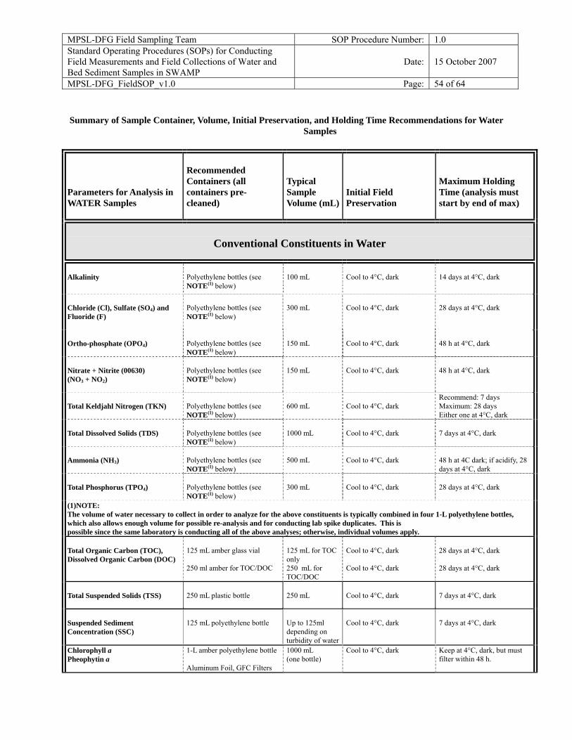
MPSL-DFG Field Sampling Team SOP Procedure Number: 1.0 Standard Operating Procedures (SOPs) for Conducting Field Measurements and Field Collections of Water and Bed Sediment Samples in SWAMP
Date: 15 October 2007
MPSL-DFG_FieldSOP_v1.0 Page: 54 of 64
Summary of Sample Container, Volume, Initial Preservation, and Holding Time Recommendations for Water
Samples
Parameters for Analysis in WATER Samples
Recommended Containers (all containers pre-cleaned)
Typical Sample Volume (mL)
Initial Field Preservation
Maximum Holding Time (analysis must start by end of max)
Conventional Constituents in Water
Alkalinity
Polyethylene bottles (see NOTE(1) below)
100 mL
Cool to 4°C, dark
14 days at 4°C, dark
Chloride (Cl), Sulfate (SO4) and Fluoride (F)
Polyethylene bottles (see NOTE(1) below)
300 mL
Cool to 4°C, dark
28 days at 4°C, dark
Ortho-phosphate (OPO4)
Polyethylene bottles (see NOTE(1) below)
150 mL
Cool to 4°C, dark
48 h at 4°C, dark
Nitrate + Nitrite (00630) (NO3 + NO2)
Polyethylene bottles (see NOTE(1) below)
150 mL
Cool to 4°C, dark
48 h at 4°C, dark
Total Keldjahl Nitrogen (TKN)
Polyethylene bottles (see NOTE(1) below)
600 mL
Cool to 4°C, dark
Recommend: 7 days Maximum: 28 days Either one at 4°C, dark
Total Dissolved Solids (TDS)
Polyethylene bottles (see NOTE(1) below)
1000 mL
Cool to 4°C, dark
7 days at 4°C, dark
Ammonia (NH3)
Polyethylene bottles (see NOTE(1) below)
500 mL
Cool to 4°C, dark
48 h at 4C dark; if acidify, 28 days at 4°C, dark
Total Phosphorus (TPO4)
Polyethylene bottles (see NOTE(1) below)
300 mL
Cool to 4°C, dark
28 days at 4°C, dark
(1)NOTE: The volume of water necessary to collect in order to analyze for the above constituents is typically combined in four 1-L polyethylene bottles, which also allows enough volume for possible re-analysis and for conducting lab spike duplicates. This is possible since the same laboratory is conducting all of the above analyses; otherwise, individual volumes apply. Total Organic Carbon (TOC), Dissolved Organic Carbon (DOC)
125 mL amber glass vial 250 ml amber for TOC/DOC
125 mL for TOC only 250 mL for TOC/DOC
Cool to 4°C, dark Cool to 4°C, dark
28 days at 4°C, dark 28 days at 4°C, dark
Total Suspended Solids (TSS)
250 mL plastic bottle
250 mL
Cool to 4°C, dark
7 days at 4°C, dark
Suspended Sediment Concentration (SSC)
125 mL polyethylene bottle
Up to 125ml depending on turbidity of water
Cool to 4°C, dark
7 days at 4°C, dark
Chlorophyll a Pheophytin a
1-L amber polyethylene bottle Aluminum Foil, GFC Filters
1000 mL (one bottle)
Cool to 4°C, dark
Keep at 4°C, dark, but must filter within 48 h.
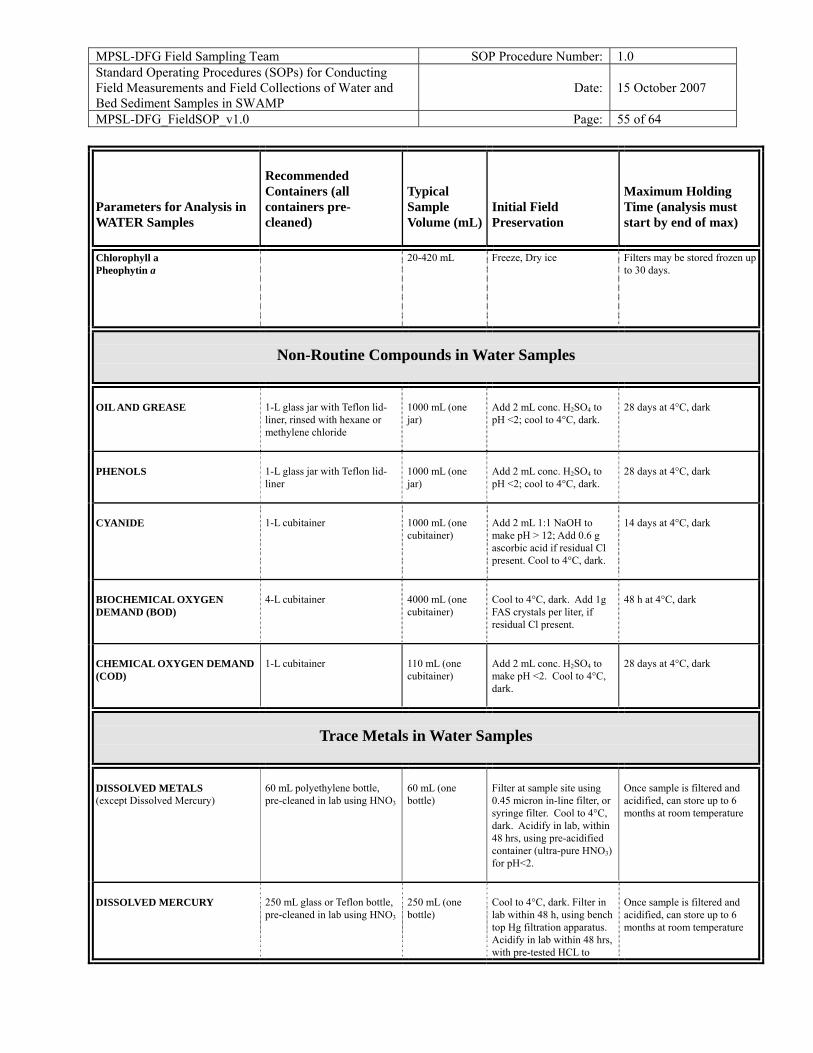
MPSL-DFG Field Sampling Team SOP Procedure Number: 1.0 Standard Operating Procedures (SOPs) for Conducting Field Measurements and Field Collections of Water and Bed Sediment Samples in SWAMP
Date: 15 October 2007
MPSL-DFG_FieldSOP_v1.0 Page: 55 of 64
Parameters for Analysis in WATER Samples
Recommended Containers (all containers pre-cleaned)
Typical Sample Volume (mL)
Initial Field Preservation
Maximum Holding Time (analysis must start by end of max)
Chlorophyll a Pheophytin a
20-420 mL Freeze, Dry ice Filters may be stored frozen up to 30 days.
Non-Routine Compounds in Water Samples
OIL AND GREASE
1-L glass jar with Teflon lid-liner, rinsed with hexane or methylene chloride
1000 mL (one jar)
Add 2 mL conc. H2SO4 to pH <2; cool to 4°C, dark.
28 days at 4°C, dark
PHENOLS
1-L glass jar with Teflon lid-liner
1000 mL (one jar)
Add 2 mL conc. H2SO4 to pH <2; cool to 4°C, dark.
28 days at 4°C, dark
CYANIDE
1-L cubitainer
1000 mL (one cubitainer)
Add 2 mL 1:1 NaOH to make pH > 12; Add 0.6 g ascorbic acid if residual Cl present. Cool to 4°C, dark.
14 days at 4°C, dark
BIOCHEMICAL OXYGEN DEMAND (BOD)
4-L cubitainer
4000 mL (one cubitainer)
Cool to 4°C, dark. Add 1g FAS crystals per liter, if residual Cl present.
48 h at 4°C, dark
CHEMICAL OXYGEN DEMAND (COD)
1-L cubitainer
110 mL (one cubitainer)
Add 2 mL conc. H2SO4 to make pH <2. Cool to 4°C, dark.
28 days at 4°C, dark
Trace Metals in Water Samples
DISSOLVED METALS (except Dissolved Mercury)
60 mL polyethylene bottle, pre-cleaned in lab using HNO3
60 mL (one bottle)
Filter at sample site using 0.45 micron in-line filter, or syringe filter. Cool to 4°C, dark. Acidify in lab, within 48 hrs, using pre-acidified container (ultra-pure HNO3) for pH<2.
Once sample is filtered and acidified, can store up to 6 months at room temperature
DISSOLVED MERCURY
250 mL glass or Teflon bottle, pre-cleaned in lab using HNO3
250 mL (one bottle)
Cool to 4°C, dark. Filter in lab within 48 h, using bench top Hg filtration apparatus. Acidify in lab within 48 hrs, with pre-tested HCL to
Once sample is filtered and acidified, can store up to 6 months at room temperature
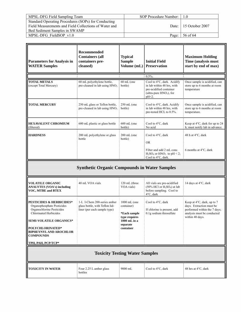
MPSL-DFG Field Sampling Team SOP Procedure Number: 1.0 Standard Operating Procedures (SOPs) for Conducting Field Measurements and Field Collections of Water and Bed Sediment Samples in SWAMP
Date: 15 October 2007
MPSL-DFG_FieldSOP_v1.0 Page: 56 of 64
Parameters for Analysis in WATER Samples
Recommended Containers (all containers pre-cleaned)
Typical Sample Volume (mL)
Initial Field Preservation
Maximum Holding Time (analysis must start by end of max)
0.5%.
TOTAL METALS (except Total Mercury)
60 mL polyethylene bottle, pre-cleaned in lab using HNO3
60 mL (one bottle)
Cool to 4°C, dark. Acidify in lab within 48 hrs, with pre-acidified container (ultra-pure HNO3), for pH<2.
Once sample is acidified, can store up to 6 months at room temperature
TOTAL MERCURY
250 mL glass or Teflon bottle, pre-cleaned in lab using HNO3
250 mL (one bottle)
Cool to 4°C, dark. Acidify in lab within 48 hrs, with pre-tested HCL to 0.5%.
Once sample is acidified, can store up to 6 months at room temperature.
HEXAVALENT CHROMIUM (filtered)
600 mL plastic or glass bottle
600 mL (one bottle)
Cool to 4°C, dark No acid
Keep at 4°C, dark for up to 24 h; must notify lab in advance.
HARDNESS
200 mL polyethylene or glass bottle
200 mL (one bottle)
Cool to 4°C, dark OR Filter and add 2 mL conc. H2SO4 or HNO3 to pH < 2; Cool to 4°C, dark.
48 h at 4°C, dark 6 months at 4°C, dark
Synthetic Organic Compounds in Water Samples
VOLATILE ORGANIC ANALYTES (VOA's) including VOC, MTBE and BTEX
40 mL VOA vials
120 mL (three VOA vials)
All vials are pre-acidified (50% HCl or H2SO4) at lab before sampling. Cool to 4°C, dark
14 days at 4°C, dark
PESTICIDES & HERBICIDES* �Organophosphate Pesticides �Organochlorine Pesticides �Chlorinated Herbicides SEMI-VOLATILE ORGANICS* POLYCHLORINATED* BIPHEYNYL AND AROCHLOR COMPOUNDS TPH, PAH, PCP/TCP*
1-L I-Chem 200-series amber glass bottle, with Teflon lid-liner (per each sample type)
1000 mL (one container) *Each sample type requires 1000 mL in a separate container
Cool to 4°C, dark If chlorine is present, add 0.1g sodium thiosulfate
Keep at 4°C, dark, up to 7 days. Extraction must be performed within the 7 days; analysis must be conducted within 40 days.
Toxicity Testing Water Samples
TOXICITY IN WATER
Four 2.25 L amber glass bottles
9000 mL
Cool to 4°C, dark
48 hrs at 4°C, dark
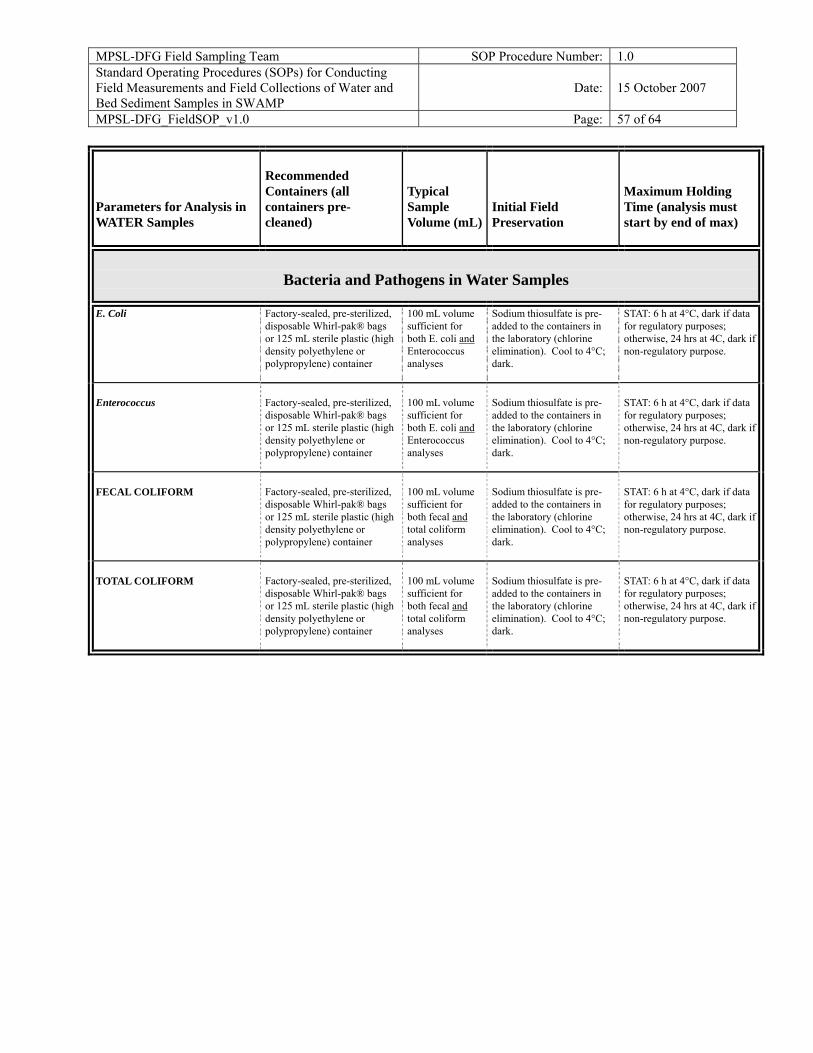
MPSL-DFG Field Sampling Team SOP Procedure Number: 1.0 Standard Operating Procedures (SOPs) for Conducting Field Measurements and Field Collections of Water and Bed Sediment Samples in SWAMP
Date: 15 October 2007
MPSL-DFG_FieldSOP_v1.0 Page: 57 of 64
Parameters for Analysis in WATER Samples
Recommended Containers (all containers pre-cleaned)
Typical Sample Volume (mL)
Initial Field Preservation
Maximum Holding Time (analysis must start by end of max)
Bacteria and Pathogens in Water Samples
E. Coli
Factory-sealed, pre-sterilized, disposable Whirl-pak® bags or 125 mL sterile plastic (high density polyethylene or polypropylene) container
100 mL volume sufficient for both E. coli and Enterococcus analyses
Sodium thiosulfate is pre-added to the containers in the laboratory (chlorine elimination). Cool to 4°C; dark.
STAT: 6 h at 4°C, dark if data for regulatory purposes; otherwise, 24 hrs at 4C, dark if non-regulatory purpose.
Enterococcus
Factory-sealed, pre-sterilized, disposable Whirl-pak® bags or 125 mL sterile plastic (high density polyethylene or polypropylene) container
100 mL volume sufficient for both E. coli and Enterococcus analyses
Sodium thiosulfate is pre-added to the containers in the laboratory (chlorine elimination). Cool to 4°C; dark.
STAT: 6 h at 4°C, dark if data for regulatory purposes; otherwise, 24 hrs at 4C, dark if non-regulatory purpose.
FECAL COLIFORM
Factory-sealed, pre-sterilized, disposable Whirl-pak® bags or 125 mL sterile plastic (high density polyethylene or polypropylene) container
100 mL volume sufficient for both fecal and total coliform analyses
Sodium thiosulfate is pre-added to the containers in the laboratory (chlorine elimination). Cool to 4°C; dark.
STAT: 6 h at 4°C, dark if data for regulatory purposes; otherwise, 24 hrs at 4C, dark if non-regulatory purpose.
TOTAL COLIFORM
Factory-sealed, pre-sterilized, disposable Whirl-pak® bags or 125 mL sterile plastic (high density polyethylene or polypropylene) container
100 mL volume sufficient for both fecal and total coliform analyses
Sodium thiosulfate is pre-added to the containers in the laboratory (chlorine elimination). Cool to 4°C; dark.
STAT: 6 h at 4°C, dark if data for regulatory purposes; otherwise, 24 hrs at 4C, dark if non-regulatory purpose.
MPSL-DFG Field Sampling Team SOP Procedure Number: 1.0 Standard Operating Procedures (SOPs) for Conducting Field Measurements and Field Collections of Water and Bed Sediment Samples in SWAMP
Date: 15 October 2007
MPSL-DFG_FieldSOP_v1.0 Page: 58 of 64
Field Collection Procedures for Bed Sediment Samples Bed sediment (hereafter termed "sediment") samples are collected after any water samples are collected where water and sediment are taken in the same reach. Care must be taken not to sample sediments that have been walked on or disturbed in any manner by field personnel collecting water samples. Sediment samples are collected into a composite jar, where they are thoroughly homogenized in the field, and then aliquoted into separate jars for chemical or toxicological analysis. Sediment samples for metals and organics are submitted to the respective analytical laboratories in separate glass jars, which have been pre-cleaned according to laboratory protocol. Sediment chemistry samples give information regarding both trends in contaminant loading and the potential for adverse effects on sediment and aquatic biota. In order to compare samples over time and from site to site, they must be collected in a consistent manner. If a suitable site for collecting sediments cannot be found at a station, sampling personnel should not collect the sediment sample, and should instead attempt to reschedule the sample collection. If this is not possible, make a note so that the missing sample is accounted for in the reconciliation of monitoring events during preparation of sample collection "cruise reports". Sites that are routinely difficult to collect should be considered for elimination or relocation from the sample schedule, if appropriate.
Characteristics of Ideal Sediment Material to be Collected
Many of the chemical constituents of concern are adsorbed onto fine particles. One of the major objectives in selecting a sample site, and in actually collecting the sample while on site, is to obtain recently deposited fine sediment, to the extent possible. Avoid hard clay, bank deposits, gravel, disturbed and/or filled areas. Any sediment that resists being scooped by a dredge is probably not recently deposited fine sediment material. In following this guidance, the collection of sediment is purposefully being biased for fine materials, which must be discussed thoroughly in any subsequent interpretive reporting of the data, in regards to representation of the collected sample to the environment from which it was collected.
Characteristics of an Ideal Site
Quiescent areas are conducive to the settling of finer materials (EPA/USACOE, 1981). Choose a sampling site with lower hydrologic energy, such as the inner (depositional) side of bends or eddies where the water movement may be slower. Reservoirs and estuaries are generally depositional environments, also.
MPSL-DFG Field Sampling Team SOP Procedure Number: 1.0 Standard Operating Procedures (SOPs) for Conducting Field Measurements and Field Collections of Water and Bed Sediment Samples in SWAMP
Date: 15 October 2007
MPSL-DFG_FieldSOP_v1.0 Page: 59 of 64
Selecting the Appropriate Sediment Type for Analysis
Sediment will vary from site to site and can vary between sample events at a particular site. Streams and Rivers: Sediment collection in flowing streams is often a challenge. In areas of frequent scouring there may not be sufficient sediment for collection during or following periods of high flow. Sediment collection during these times may prove unsuccessful and may have to be rescheduled or cancelled. When the suspended load in rivers and streams precipitates due to reduction of velocity, most of the resulting sediment will be fine- grained. More often than not, a dredge or mechanical grab device does not function well for collection of sediment in smaller streams. In many cases, sediment will have to be collected using a pre-cleaned polyethylene scoop. Collect the top 2 cm for analysis. Five or more (depending on the volume of sediment needed for conducting analyses) fine-sediment sub-sites within a 100-m reach are sampled into the composite jar. Reservoirs and Estuaries: Collect the top 2 cm for analysis. Five or more grabs are composited for the sediment sample, depending on the volume of sediment needed for conducting analyses.
GENERAL PROCEDURE FOR COLLECTION OF BED SEDIMENT
After choosing an appropriate site, and identifying appropriate fine-grained sediment areas within the general reach, collect the sample using one or more of the following procedures, depending on the setting:
A. Sediment Scoop Method—Primary Method for Wadeable, Shallow Streams
• The goal is to collect the top 2 cm of recently-deposited fine sediment only. • Wear gloves and protective gear, in areas of potential exposure hazards, per appropriate
protocol (make sure gloves are long enough to prevent water from overflowing gloves while submerging scoop).
• Survey the sampling area for appropriate fine-sediment depositional areas before stepping into the stream, to avoid disturbing possible sediment collection sub-sites.
• Carefully enter the stream and start sampling at the closest appropriate reach, then continue sampling UPSTREAM. Never advance downstream, as this could lead to sampling disturbed sediment.
• Stir, do not shake, collected sediment with a polyethylene scoop for at least 5 min making
MPSL-DFG Field Sampling Team SOP Procedure Number: 1.0 Standard Operating Procedures (SOPs) for Conducting Field Measurements and Field Collections of Water and Bed Sediment Samples in SWAMP
Date: 15 October 2007
MPSL-DFG_FieldSOP_v1.0 Page: 60 of 64
sure all sediment is completely homogenized. • Quickly scoop sediment out of the homogenizing jar into desired sampling jars making
sure to stir the sediment in the homogenizing jar in between each aliquot. • Inspect each individual sediment jar making sure of consistent grain size throughout the
entire sample collection. • Single bag all sediment containers to prevent cross contamination. • Make sure all containers are capped tightly and stored in a cooler on cube ice at 4 °C. • Check cooler temperature and record in log book every 8-12 h or whenever sampler
suspects that the temperature has not been maintained at 4 °C.
B. Hand Core Method-Alternate method for wadeable shallow streams with fine sediment
• A hand core is used in wadeable streams where there is very fine sediment. • The hand core sampler consists of a 3-in. diameter polycarbonate core that is 8 inches
long. Samplers push the core into the sediment to the desired depth, pull the core out of the sediment, and cap the bottom with a polyethylene core cap or by placing their hand underneath the cap to hold the sediment in place.
• Hand cores are usually measured and marked at 2 cm length so the sampler knows how far to deploy the core into the sediment.
• Sediment is then emptied into a homogenizing jug and aliquoted accordingly. C. Sediment Grab Method—Primarily for Lake, River, Bridge, and Estuarine
Settings (or deeper streams) Description of sediment grab equipment:
• A mechanical sediment grab is used for the SWAMP bed sediment collection field effort for lake, river, bridge, and estuarine/coastal settings (or deeper, non-wadeable streams).
• The mechanical grab is a stainless steel “Young-modified Van Veen Grab", and is 0.5 m2 in size.
• The mechanical grab is deployed primarily from a boat, and is used in deeper, non-wadeable waters, such as lakes, rivers, estuaries, and coastal areas.
• It is also deployed by field personnel from land in settings which allow its use: primarily from bridges; from smaller vessels in streams or drainage channels too deep or steep to wade into, but too shallow for a larger boat.
Deploying and retrieving the grab:
• Slowly lower the grab to the bottom with a minimum of substrate disturbance. • Retrieve the closed dredge at a moderate speed (e.g., less than two feet per second). • Upon retrieval, open the lids of the sediment grab, examine the sample to ensure that the
sediment surface is undisturbed and that the grab sample should not be rejected.
MPSL-DFG Field Sampling Team SOP Procedure Number: 1.0 Standard Operating Procedures (SOPs) for Conducting Field Measurements and Field Collections of Water and Bed Sediment Samples in SWAMP
Date: 15 October 2007
MPSL-DFG_FieldSOP_v1.0 Page: 61 of 64
Rejection Criteria—reject the sample if the following are not met: • Mud surface must not be pressing out of the top of the sampler. If it is, lower the grab more
slowly. • Overlying water must not be leaking out along the sides of the sediment in the grab. This
ensures the surficial sediment is not washed out. • Sediment surface is flat and level in the sampler. If it is not level, the grab has tilted over
before closing.
Processing the sediment sample from the grab equipment: • The water overlying the sediment in the grab is very gently decanted by slightly tipping
the grab with the lid closed until the water runs out the top. • The decanting process should remove all of the overlying water but not remove the
surficial sediments. The laboratory reports percent water for the sample, so overlying water is not included in the sample container.
• The sediment is examined for depth of penetration, color and thickness of top aerobic zone, and texture. These observations are recorded in the logbook.
• Collect the top 2 cm from at least five sub samples, and otherwise, exclude the bottom-most layer and composite.
• In streams or other settings with excessive bottom debris (e.g., rocks, sticks, leaves) where the use of a grab is determined to be ineffective (e.g., dredge does not close, causing loss of sediment), samples may be collected by hand using a clean plastic scoop, or by a variety of coring methods, if appropriate for the situation.
• Sediment is handled as described below in the metals and organic sections. Cleaning the Grab Equipment and Protection from Potential Contaminating Sources:
• The sediment sampler will be cleaned prior to sampling EACH site by: rinsing all surfaces with ambient water, scrubbing all sediment sample contact surfaces with Micro™ or equivalent detergent, rinsing all surfaces with ambient water, rinsing sediment sample contact surfaces with 5% HCl, and rinsing all sediment sample contact surfaces with methanol.
• The sediment grab will be scrubbed with ambient water between successive deployments at ONE site, in order to remove adhering sediments from contact surfaces possibly originating below the sampled layer, thus preventing contamination from areas beyond target sampling area.
• Sampling procedures will attempt to avoid exhaust from any engine aboard any vessel involved in sample collection. An engine will be turned off when possible during portions of the sampling process where contamination from engine exhaust may occur. It is critical that sample contamination be avoided during sample collection. All sampling equipment (e.g., siphon hoses, scoops, containers) will be made of non-contaminating material and will be appropriately cleaned before use. Samples will not be touched with un-gloved fingers. In addition, potential airborne contamination (e.g., from engine exhaust, cigarette smoke) will be avoided.
MPSL-DFG Field Sampling Team SOP Procedure Number: 1.0 Standard Operating Procedures (SOPs) for Conducting Field Measurements and Field Collections of Water and Bed Sediment Samples in SWAMP
Date: 15 October 2007
MPSL-DFG_FieldSOP_v1.0 Page: 62 of 64
D. Core Method--alternative for fast-moving, wadeable streams The core method is used in soft sediments when it is difficult to use the other methodologies. The cores can be used in depths of water from 0 to 10 ft by using a pole deployment device or in deeper water using SCUBA divers. The pole deployment device consists of a pole that attaches to the top of the core. The top of the core is fitted with a one-way valve, which allows the core to be filled with sediment, but when pulled from the sediment catches the sediment within the core. The core is then brought to the surface and the sediments within the core are extruded out the top of the core so that 2 cm of sediment is above the top of the plastic core. The 2 cm of sediment is then sliced off and placed in the homogenizing jar. A new core, homogenizing jar, and device used to slice off the top two cm. are used at each station unless the equipment is cleaned using laboratory protocols. E. Sediment Grab Method – Primarily used from bridges or for streams with restricted bank access. Description and sampling procedure for the Eckman sediment grab
• The Eckman grab is 0.2 m2 in size with a lead “messenger” that triggers the spring loaded doors.
• The primary use is for sampling from bridges or from small vessels in streams or drainage channels too deep or steep to wade into, but too shallow for a larger boat.
• The grab must be cleaned with a Micro™ and tap water rinse before sampling and in-between sample stations.
• To deploy the grab, pull the spring loaded doors open and hook the cables on the actuator plate.
• With a rope, lower the grab to the desired sample reach making sure that the grab has penetrated the sediment. Clip the “messenger” on the rope and release it while maintaining tension on the rope. Pull up the grab once the “messenger” has activated the doors.
• While wearing clean poly gloves, open the top hatch and remove the top 2 cm of sediment with a clean polyethylene scoop. Place the sediment into the homogenizing jug and repeat the sampling process until there is enough desired sediment. See general procedures for processing of bed sediment samples, once they are collected for sediment homogenization and aliquoting into sample jars.
GENERAL PROCEDURE FOR PROCESSING OF BED SEDIMENT
SAMPLES, ONCE THEY ARE COLLECTED Sediment Homogenization, Aliquoting and Transport For the collection of bed sediment samples, the top 2 cm is removed from the scoop, or the grab, or the core, and placed in the 4-L glass compositing/homogenizing container. The composited sediment in the container is homogenized and aliquoted on-site in the field. The sample is stirred
MPSL-DFG Field Sampling Team SOP Procedure Number: 1.0 Standard Operating Procedures (SOPs) for Conducting Field Measurements and Field Collections of Water and Bed Sediment Samples in SWAMP
Date: 15 October 2007
MPSL-DFG_FieldSOP_v1.0 Page: 63 of 64
with a polyethylene scoop for at least 5 min, but longer if necessary, until sediment/mud appears homogeneous. All sample identification information (station numbers, etc.) will be recorded prior to homogenizing and aliquoting. The sediment sample is then aliquoted, using a clean plastic scoop, into appropriate containers for trace metal chemistry, organic chemistry, and toxicity testing. All sample containers will be packed surrounded by enough ice to keep them cool for 48 h. Each container will be sealed in one large plastic bag to prevent contact with other samples or ice or water.
Metals and Semi-volatile Organics in Sediment
For trace metals and semi-volatile organics, a minimum of three grabs is distributed to the composite bottle and/or sample containers. Mixing is generally done with a polyethylene scoop. Make sure the sample volume is adequate, but the containers do not need to be filled to the top. Seal the jars with the Teflon liner in the lids.
Sediment Conventionals
Sediment conventionals are sometimes requested when sediment organics, sediment metals, and/or sediment toxicity tests are requested for analysis of samples. The collection method is the same as that for metals, semi-volatile organics, and pesticides. Sediment conventionals include: grain size analysis and total organic carbon. These are used in the interpretation of metals and organics in sediment data.
Sample Containers See “Sediment Sample Handling Requirements” table at end of this document.
Sediment Sample Size
Must collect sufficient volume of sediment to allow for proper analysis, including possible repeats, as well as any requested archiving of samples for possible later analysis. See “Sediment Sample Handling Requirements” Table at end of this document.
Labeling Label the jars with the station ID, sample code, matrix type, project ID, time, and date of collection, as well as the type of analysis requested (e.g., metals, conventionals, organics, or archives).
Short-term Field Preservation
Immediately place the labeled jar on ice, cool to 4 °C, and keep in the dark at 4 °C until delivery to the laboratory.
Field Notes Fill out the SWAMP Station Occupation Data Sheet and the Sediment Data Sheet. Make sure to record any field notes that are not listed on the provided data sheets. This information can be reported as comments with the sediment analytical results.
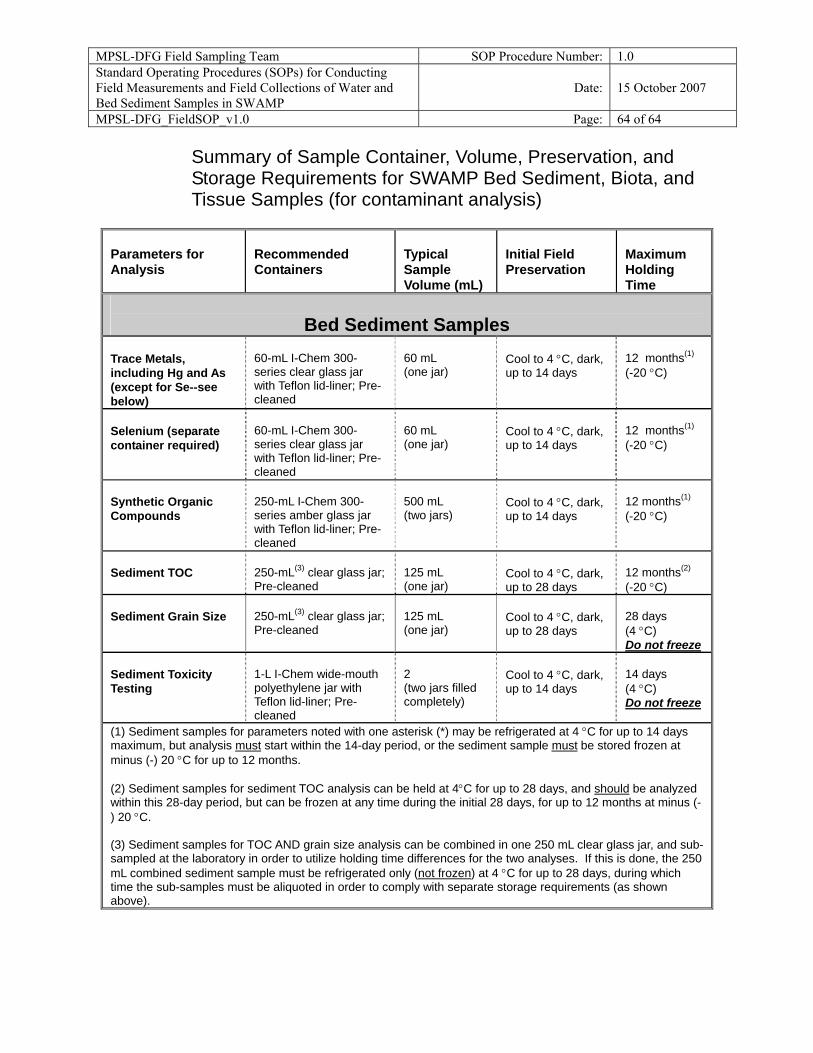
MPSL-DFG Field Sampling Team SOP Procedure Number: 1.0 Standard Operating Procedures (SOPs) for Conducting Field Measurements and Field Collections of Water and Bed Sediment Samples in SWAMP
Date: 15 October 2007
MPSL-DFG_FieldSOP_v1.0 Page: 64 of 64
Summary of Sample Container, Volume, Preservation, and Storage Requirements for SWAMP Bed Sediment, Biota, and Tissue Samples (for contaminant analysis)
Parameters for Analysis
Recommended Containers
Typical Sample Volume (mL)
Initial Field Preservation
Maximum Holding Time
Bed Sediment Samples
Trace Metals, including Hg and As (except for Se--see below)
60-mL I-Chem 300- series clear glass jar with Teflon lid-liner; Pre-cleaned
60 mL (one jar)
Cool to 4 °C, dark, up to 14 days
12 months(1)
(-20 °C)
Selenium (separate container required)
60-mL I-Chem 300- series clear glass jar with Teflon lid-liner; Pre-cleaned
60 mL (one jar)
Cool to 4 °C, dark, up to 14 days
12 months(1)
(-20 °C)
Synthetic Organic Compounds
250-mL I-Chem 300- series amber glass jar with Teflon lid-liner; Pre-cleaned
500 mL (two jars)
Cool to 4 °C, dark, up to 14 days
12 months(1)
(-20 °C)
Sediment TOC
250-mL(3) clear glass jar; Pre-cleaned
125 mL (one jar)
Cool to 4 °C, dark, up to 28 days
12 months(2)
(-20 °C) Sediment Grain Size
250-mL(3) clear glass jar; Pre-cleaned
125 mL (one jar)
Cool to 4 °C, dark, up to 28 days
28 days (4 °C) Do not freeze
Sediment Toxicity Testing
1-L I-Chem wide-mouth polyethylene jar with Teflon lid-liner; Pre-cleaned
2 (two jars filled completely)
Cool to 4 °C, dark, up to 14 days
14 days (4 °C) Do not freeze
(1) Sediment samples for parameters noted with one asterisk (*) may be refrigerated at 4 °C for up to 14 days maximum, but analysis must start within the 14-day period, or the sediment sample must be stored frozen at minus (-) 20 °C for up to 12 months. (2) Sediment samples for sediment TOC analysis can be held at 4°C for up to 28 days, and should be analyzed within this 28-day period, but can be frozen at any time during the initial 28 days, for up to 12 months at minus (-) 20 °C. (3) Sediment samples for TOC AND grain size analysis can be combined in one 250 mL clear glass jar, and sub-sampled at the laboratory in order to utilize holding time differences for the two analyses. If this is done, the 250 mL combined sediment sample must be refrigerated only (not frozen) at 4 °C for up to 28 days, during which time the sub-samples must be aliquoted in order to comply with separate storage requirements (as shown above).