Embed Size (px)
Citation preview
AT&T PRACTICE
StandardAT&T 314-900-100
Issue 5, April 1985
f-
P
PRIVATE LINE SERVICE
OVERALL DESCRIPTION
DIGITAL DATA SYSTEM
CONTENTS PAGE
I. GENERAL . . . . . . . . . . .
2. INTRODUCTION . . . . . . . . .
A. System Summary . . . . . . .
B. Comparison of Analog and Digital
Transmission . . . . . . . .
c. Integration into Present Digital Hierar-
chy . . . . . . . . . . . .
3. DDS SIGNAL STRUCTURE . . . . . .
A.
B.
c.
D.
E.
Customer Stations and Local Loops .
Mtce Channel Terminating Equipment
. . . . . . . . . . . . .
Signal Format and Protocols for Second-
ary Channel Capability . . . . .
First Stage Multiplexing . . . . .
Second Stage Multiplexing . . . .
4. NETWORK STRUCTURE . .
A. End-to-End Connection
B. Long-Haul Transmission
c. Short-Haul Transmission
D. Digital LATA Serving Area
E. Local loops . . . .
F. Off-Net Extensions .
. . . . .
. . . . .
. . . . .
. . . . .
. . . .
. . . . .
. . . . .
5. EQUIPMENT FUNCTIONAL DESCRIPTION .
2
3
3
3
3
5
5
5
7
9
9
10
10
10
12
12
14
14
15
A.
B.
c.
D.
CONTENTS PAGE
Introduction . . . . . . . . . 15
Customer Stations . . . . . . . 15
Office Equipment . . . . . . . 15
Long-Haul Equipment . . . . . 20
6. NETWORK SYNCHRONIZATION . . . .
7. DDS BAY ARRANGEMENTS . . . . .
A. Equipment Assemblies . . . . .
B. Equipment Bays . . . . . . .
c. Equipment Addressing . . . . .
8. MULTIPOINT SERVICE . . . . . . .
9. MAINTENANCE FEATURES . . . . . .
A. Automatic Monitoring and Protection
Switching . . . . . . . . .
B. Alarm and Status Indications . . .
c. Status Bytes . . . . . . . . .
D. Loopback Tests . . . . . . . .
E. Test Access . . . . . . . . .
F. DDS DS-O Loop Codes . . . . .
G. DOSS . . . . . . . . . . .
10. REFERENCES . . . . . . . . . .
11. GLOSSARY . . . . . . . . . . .
22
23
23
23
25
27
27
27
28
28
28
28
29
29
29
31
AT&T TECHNOLOGIES, INC. - PROPRIETARY
Printed in U.S.A. Page 1
AT&T 314-900-100
BFigures
1.
2.
3.
4.
5.
6.
7.
8.
9.
10.
11.
12.
13.
14.
15.
Tables
A.
B.
c.
D.
E.
CONTENTS PAGE
Digital Data System With Secondary Chan-
nel Capability . . . . . . . . . 4
DS- 1 Transmission Facilities . . . . . 6
Bipolar Formats . . . . . . . . . 7
Output signa[s . . . . . . . . . 8
Frame of T1 Data Stream . . . . . 10
Digital Data System Hierarchy Block Dia-
gram . . . . . . . . . . ..11
Diagram of DDS inter-1.ATA Routing Struc-
ture . . . . . . . . . ...12
DDS Off-Net Extension . . . . . . 14
Example of DLSA Structure . . . . . 16
Block Diagram of Hub OWtce Using ABATS
. . . . . . . . . . . . . . 21
Synchronous Timing Network . . . . 23
Timing Waveforms . . . . . . . . 24
Typical DDS Equipment Assembly . . . 24
Station Multipaint Ckcuit . . . . . 27
Cascading of MJUS . . . . . . . 28
CUSTOMER BYTE FORMATS AND DATA
RATES . . . . . . . . . . . .5
BYTE STUFFING . . . . . . . . . 9
EFFECT OF MULTIPLEXING . . . . . 10
BAY SHELF POSITION NUMBER MEANING
IN AN SRDM . . . . . . . ..26
BAY SHELF POSITION NUMBER MEANING
IN AN ISMX . . . . . . . . ..26
CONTENTS
F. BAY SHELF POSITION NUMBER
IN ANOCU . . . . . .
PAGE n,,
MEANING
. . . . 27
G. DDS NETWORK CONTROL CODES . . . 30 ~
H. DDS DATA MODE CODES . . . . . 31
.1. REFERENCES FOR CUSTOMER STATION
ARRANGEMENTS AND LOCAL LOOPS . 32
t
J. REFERENCES FOR GENERAL OFFICE EQUIP-
MENT . . . . . . . . . . ..33?
K. REFERENCES FOR TRANSMISSION . . . 36
1. GENERAL
1.01 This practice provides an overall transmissiondescription of the private line service for the
DDS (Digital Data System). The description is basedon the integration of several individual componentsinto a system meeting a set of overall transmissionobjectives.
?,1.02 This practice is reissued for the following rea-
sons:
To add new terms throughout the practice asa result of new technologies and divestiture
To describe test equipment necessary forturn-up and maintenance
To add information on the level of spare cir-cuit packs necessary for proper operation
To delete coverage of and reference to the m,950A testboard
To replace DSU/CSU (data service unit/.
channel service unit) terminology with DTE(digital terminating equipment) terminology *
.
To add information on the hierarchical struc-ture and boundaries of intra- and inter- ?LATA (local access and transport area)
To add references to the ABATS (AutomatedBit Access Test System) and the DTSS (Digi-tal Transmission Surveillance System) -,
Page 2

1SS 5, AT&T 314-900-100
,P’
,n
/-
● To add information on secondary channelcapability.
Revision arrows are used to emphasize the more sig-nificant changes.
2. INTRODUCTION
A. System Summary
2.o1 The DDS is a general purpose facility networkfor data transmission. A major use of the net-
work is for a private line synchronous data transmis-sion service. Data transmission occurs in bothdirections simultaneously (full duplex transmission).A synchronization network ensures the transmissionis synchronous; that is, the data is accepted from anddelivered to the DDS at network-controlled clocktimes.
2.o2 The DDS provides point-to-point andmultipoint (multistation) service. Multipoint
service eliminates the need for an individual dataroute between a centralized customer location andeach of its branches. The DDS accepts data rates of2.4,4.8, 9.6, and 56 kb/s. There is no provision for al-ternate voice or voice coordination. The basic datarates are multiplexed to achieve efficient fills on thetransmission facilities and on shared equipment. Of-fices are arranged in a hierarchy from hub offices toend offices. A hub office serves as the cross-connectand testing point for all circuits that have end pointsin the office serving area.
2.03 *A new feature called secondary channel ca-pability is being introduced in the DDS. This
feature provides an independent, lower speed channelthe customer can use to control or monitor its ownnetwork. This channel will operate in parallel withthe primary data channel through the DDS networkand will have comparable quality. To implement sec-ondary channel capability, the excess capability in-herent in the eighth bit (network control bit) of eachnetwork byte will be shared with the customer.
2.04 Secondary channel capability will be providedon all customer data rates and circuits (2.4,
4.8, 9.6, and 56 kb/s) and will use the same basic net-work equipment and transmission facilities as theprimary channel. Figure 1 is a block diagram of theDDS with secondary channel capability plus the newor modified equipment codes necessary for secondarychannel capability.
2.05 Secondary channel capability will be derivedat the DTE and can be used independently of
the primary channel. To support secondary channeloperation in the DDS, every third control bit is re-placed by a secondary channel bit. The resulting sec-ondary channel capacity at the different customerrates is shown in Table A4.
B. Comparison of Analog and Digital Transmission
2.06 The DDS is designed to transmit data in digi-tal form. A bit is a unit of digital information.
Bits are represented by the presence or absence ofpulses during a specific interval of time and are com-monly known as ones (pulses) and zeros (no pulses).Once the pulses have been formed, the exact ampli-tude is of little significance; therefore, digital pulsesmay be freely regenerated between two points oftransmission. The only restriction on regeneration isthat it must occur before extraneous signals andnoise have obscured the ones and zeros. This risk oferror is minimized by the proper spacing of regenera-tors. Noise and distortion that normally accumulatein analog signals are completely removed each timea digital signal is regenerated. In addition, the DDS,being strictly digital from end to end, eliminates theneed for the digital-to-analog-to-digital conversionrequired by analog data transmission facilities. Thiseliminates the cost and complexity of extra equip-ment and the distortion caused by repeated conver-sions.
c. Integration into Present Digital Hierarchy
2.07 The DDS has been designed to be integratedinto the digital hierarchy, which is divided
into levels according to data rate. The higher the datarate, the higher the level in the hierarchy. A 1.544-Mb/s rate defines the first level in the hierarchy,called the DS-1 level. The DDS transmits to thesefacilities at the DS-1 level. This level may be multi-plexed into higher rate facilities, but it is still usedas a DS-1 facility (Fig. 2). Facility information is doc-umented in the appropriate division of practices ac-cording to the type of facility.
2.08 The DDS circuits must be changed to imple-ment the secondary channel capability for the
following reasons:
(a) The loop signal format must be changed toprovide for increased information transmis-
sion rate.
Page 3

AT&T 3W9OO-1OO
tDS 1
OcuHL 220
O/T SROII
‘ - “s ,
TIDH-PME/W
I HL 29
I(NOTE 1)
Ocu ~HL 220 lSMX TIDM
E/W
I HL 216
B
I II I
MJUHL 223/4
~F]@&
=-wq+~
(LOOP SIOE ‘;;BINTERFACE) HL Bee
t ?OSOA OSOB
tLOOP
NOTE:1. This circuit pack will be modified
with a Class A change.
$Fig.l-Digital Data System With Secondary Channel Capabilitfl
(b) The method by which the secondary channelinformationis carried within thenetworkpro-
ducesdata bytes which contain more zeros thanthose produced by the existing system. The exist-ing equipment, in many cases, will suppress thesebytes so theequipment mustbe modified totrans-mit the information.
(c) Processing of secondary channel informationis added to the MJU (multipoint junction unit).
(d) Subrate circuit assignment is restricted tothose channels within a DS-OB signal that
contains a one in the subrate framing bit, and 56kb/s customers cannot transmit all-zeros datawith a zero in the secondary channel.q
-’l
‘q
.
2.09 The 1.544-Mb/s DS-1 signal is organized intoframes of 193 bits each. Each frame is subdi-
vided into twenty-four 8-bit bytes, accounting for 192bits. The 193rd bit is used for frame synchronization.A rate of 8,000 frames per second can be derived by
‘7
dividing the total number of bits per second by thenumber of bits per frame (1,544,000 divided by 193). .
Each of the twenty-four 8-bit bytes represents onechannel. Therefore, each channel contains informa-tion at the rate of 64 kb/s (8 bits x 8000 frames per .
second), and the DS-1 signal consists of twenty-four64-kb/s data channels multiplexed into a single1.544-Mb/s data stream. Typically, the 24th channel
n,
byte is used for frame synchronization (in addition tothe 193rd bit), so only the first 23 bytes in a framecarry customer data.
n,
Page 4

1SS5, AT&T 314-900-100
*TABLE A4
CUSTOMER BYTE FORMATS AND DATA RATES
OVERALL CHANNEL
PRIMARY SECONDARY RATE ATBYTE FORMAT CHANNEL CHANNEL NETWORK
(NOTE 1) RATE RATE INTERFACE
D, DZD,,D,D,D, F C/S 2.4 kb/s 133 1/3 b/s 3.2 kb/s
D, D,D:ID,D,D, F C/S 4.8 kb/s 266 2/3 b/s 6.4 kb/s
DlDzD,D4D,Db F C/S 9.6 kb/s 533 1/3 b/s 12.8 kb/s
DlDzDxD4D~DGDT F C/S 56.0 kb/s 2666 2/3 b/s 72.0 kb/s
Note:● D1.r = primary channel data
● F = framing signal (repeated 101100 pattern) ,
● c/s = shared secondary channel data (s) and network control (c) infor-mation (repeated secondary channel capability pattern).
2.10 $If secondary channel capability is present,
Pthe control bit is used for any secondary chan-
nel information. The customer can use the control bitin every third byte at all subrate speeds as well as 56kb/s channels.+
2.11 The 64-kb/s data rate is called the DS-O level.Each DS-O channel can carry customer data
from a single 56-kb/s station or from several subratestations. A DS-O level signal is divided into two typesof signals: DS-OA and DS-OB (described in paragraph3.14).
2.12 The DS-CS (digital signal at the customer ser-P vice) level represents the customer data rate
(2.4, 4.8,9.6, or 56 kb/s).
.3. DDS SIGNAL STRUCTURE
A. Customer Stations and Local Loops
P3.01 The DDS channel is terminated at the cus-
tomer location in one of two possible equip-ment arrangements. In one arrangement, thecustomer provides the timing recovery and interfacecircuitry. The DDS provides loop cable equalization
P and maintenance testing capabilities. In the other
arrangement, a single piece of DDS equipment at thecustomer location provides these functions.
3.02 The connection between the customer and theoffice is a 4-wire loop. A balanced bipolar sig-
nal is transmitted over this local loop. The signal isstill at the customer data rate and is in a modifiedBPRZ (bipolar return-to-zero) format as shown inFig. 3A. Signaling capability is provided by transmit-ting successive pulses of the same polarity, deliber-ately violating the bipolar encoding rule. This type ofsignaling is used for two main purposes. (1) to showthat a channel is idle, and (2) to perform loop-backtests over the local loop.
B. Office Channel Terminating Equipment
3.03 In a DDS office, the local loop is terminated byan OCU (office channel unit) that receives
data from and transmits data to the customer. TheOCU provides byte organization and timing and pro-duces a 64-kb/s (DS-O level) signal toward the net-work. Figure 3B shows that the output of the OCUtoward the network is always in a 64-kb/s BPNRZ(bipolar nonreturn-to-zero) format. The OCU DP (of-fice channel unit dataport) is a special servicesplug-in unit for use in digital channel banks and theremote terminal of an SLCQ 96 carrier system. The
Page 5

TYPICAL INTER-LATA FACILITIES(DUV, DOV, VIOAR201tb/s)
HUB HUBOFFICE OFFICE
TYPICAL INTRA-LATA FACILITIES
A
INTERMEDIATE(Tl, TIC, TIO, T1/OS, T2, T4M) OFFICE
COLLECTIONOFFICE
END ENDOFFICE OFFICE
OFig.2-DS-l
OCUDPservesthe samefunctionsas theOCUunlessit is specified for a different function.
3.o4 The56-kb/scustomerdatastream is dividedinto 7-bit bytes of information atthe OCU.To
eachofthese bytes, oneC(control) bitisadded,form-ing a sequence of8-bit bytes. The control bit isaoneif the byte contains customer data, or a zero if thebyte contains network control information such asthe idle code. This control bitis used totransmitsec-ondary channel information. Since a 56-kb/s datastream is organized into eight thousand 7-bit bytesevery second, an extra bit added to each byte meansthat8000additional bitsareaddedto thestreameachsecond.Theresultisa64-kb/s (DS-O level) stream.
3.o5 The subrate (2.4-, 4.8-, and 9.6-kb/s) datastreams are organized into 6-bit information
bytes. An additional bit, azero, isadded atthe frontofeach byte for later usebya multiplexer. A controlbit is added at the end. The subrate byte is then re-peated the number of times required to achieve the
&ENDOFFICE
Transmission Facilities~
.4,
64-kb/s rate (a technique known as byte stuffing).For example, at the 9.6-kb/s data rate, 9600 customerdata bits are sent toward the network every second.Two bits are added for every six of these to formbytes, a total of 3200 more bits every second. Eachbyte is repeated five times. The mathematics of thisexample of byte stuffing is (9600 + 3200) x 5 =64 kb/scoming from the OCU every second. Figure 4 showsthe output signals of an OCU toward the network and ?,illustrates byte stuffing.
3.06 OEven after the customer data has been byte .
stuffed, the information rate is still the sameas it was originally. The bytes have merely been re-peated enough (according to customer rate) to .
achieve a 64-kb/s data stream. The data stream isthen at the DS-OA signal level; that is, it containsdata from only one customer. *
Page 6

1SS 5, AT&T 314-900-100
.
P
II I
B I POLAR RETIJRN-TO-ZERO (BPRz )I
(u5ED ON cy LOCU5 + - DS-CS)
i
T
/
I I /
1
II
I IL, I II
I I
/ II
I
B.
I II
I
IBI pOLAR NONRETURN-TO-2ER0 (BPNRz)
(USED I N 00s OFFICES - OS-DA, DS-OB)
I/
I
I
I
I I I I I I111110[1 lot
+,ON THE LOOP I TSELF, THI S bI GNAL I 5 SHAPEU TO ELI MI NATE UNWANTED FREQUENCI ES.
Fig. 3—Btpolar Formats
c. Signal Format and Protocols for Secondary Channel
Capability
f+’=3.o7 Secondary channel capability requires the
imposition of a byte structure on the user data. which allows differentiation of the primary and sec-
ondary channel information, both at the user equip-ment and in the network.
Byte Structure
P 3.08 Information transmitted to the network mustbe formatted in either 8-bit bytes containing
6 primary channel data bits (D bits) for primarychannel rates of 2.4, 4.8, and 9.6 kb/s, or 9-bit bytes
pcontaining 7 primary channel bits for 56 kb/s pri-
mary channel data. Each byte contains two bitswhich are not primary channel data. One of these twobits contains a framing sequence (F bit). The otherbit is shared between secondary channel information(S bits) and network control information (C bits) and,thus, designated S/C bit. Table A shows the formatand the capacity of the primary and secondary chan-nels to carry this information, and the overall chan-nel transmission rates.
Secondary Channel Information (S Bit)
3.o9 The secondary channel information is carriedthrough the network on a specified bit which
is time shared with network control information. Ontwo-point circuits and in the control station to tribu-
Page 7

BIT POSITION
IN BYTE
56- KB/SFORMAT
9.6-K81S
fORMAT
4.8-KB/’SrORMAT
2.4-RB~fORMAT
I 23 456 7 8 I 23 45 ● ***
D D D DO o DC o ODDD D Dc ““”””
DATA BYTENO. I
OD D o 00 DC
\DATA 8YTf w
ma. I
O DDD 00 D C\
OATA BYTE ‘uNO. I
o DODD DD c!1\
OATA BYTE ‘JNo.IC-CONTROL 01 T *D-DATA 01 T
OATA BYTENo. 2
4 STUff t
[~’’’””~
O DOO O 0 DC . . ● .
BYTESOATA 13YTC
No. 2
9 STUFF t
[[’’’’’”~
0000 DOOC”” ““
BYTESOATA BYTE
No. 2
tary station direction of multipoint circuits, everythirdS/Cbitmay beusedtocarry secondary channelinformation.Fewer bitsmaybeused ifdesired. Intheopposite direction of transmission on multipoint cir-cuits, every third bit must be used when the second-ary channel is active. Framing circuits in thenetwork multipoint junction units depend on thischaracteristic.
* THE CONTROL Bi T I S A LOGICAL I IF THE BYTf CONTAINS CUSTOMEROATA,AMO A LOGICAL o IF THE eY7f CONTAINS cONTROL INFORMATION (FOR EXAMPLE,CONTROL INFORNATIIW I NOI CATING IOLE COOE IS 11!1110).
t A STUFF BYTE IS A REPETITION OF THE PREVIOUS DATA BYTE (IE,IS REPEATEO THE NUMBEROF TINES INDICATED).
Fig. 4—Output Signals
DATA BYTE NO. I
3.10 The network delay for primary and secondarychannels will be identical for two-point cir-
cuits and for the control station to tributary stationdirection of transmission in multipoint circuits. Fortransmission from tributary stations to the controlstation, delay will be experienced in the secondarychannel which will not exceed three bits at the sec-
.
19 STUFF t
(l’lII1]I!
00 DOOO DC** ● .
BYTES( OATA BYTE
No. 2
‘-)
ondary channel rate for each multipoint junctionunit in the circuit.
Two-Point Circuits
3.11 Secondary channel data may be encoded asdesired for 2.4,4.8, and 9.6 kb/s primary chan-
nel circuits. For 56 kb/s operation, the S-bit must beset at 1 when the primary channel data is set at allzeros. Note that a byte containing all zeros primary <channel data and a zero S-bit will be overwritten bythe network with the sequence OOO11OOFO.
?Multipoint Circuit
3.12 The downstream transmission of secondarychannel information, from the control station
7
‘7,
.
Page 8
.
P’
f-
to the tributaries, operates in the broadcast modeand may be treated as a two-point circuit.
3.13 In the upstream direction, the primary andsecondary channels may be operated indepen-
dently. They may have common or different sources.~
D. First Stage Multiplexing
3.14 First stage multiplexing is necessary to makesecond stage multiplexing more efficient. If
the 64-kb/s DS-OA signal is formed from a 56-kb/scustomer data rate, each byte contains new customerdata. The 8000 bits added each second to the 56-kb/scustomer data rate are all supervisory bits. None ofthe customer bytes are repeated, and a DS-OA signalthat contains the 56-kb/s customer rate bypassesfirst stage multiplexing since it is already carryingthe maximum amount of customer information. TheDS-OA signals formed from subrate customer inputs(2.4, 4.8, and 9.6 kb/s) use byte stuffing to reach the64-kb/s rate. Table B shows the number of times eachsubrate information byte is repeated to form a 64-kb/s signal. For example, a 2.4-kb/s information bytemust be repeated 20 times each second to reach theDS-OA level. The first stage multiplexer time divisionmultiplexes 20 different DS-OA signals into a singleDS-OB signal that contains 20 different 2.4-kb/s in-formation bytes. Therefore, a DS-OB level signalcould contain data from as many as 20 customers.The numbers in Table A also represent how manysubrate channels can be multiplexed together by thefirst stage multiplexer.
3.15 To achieve maximum packing efficiency, a dif-ferent multiplexer is required for each
subrate. Because of the uniform 64-kb/s data streamcoming from the OCU, a first stage multiplexer canaccept data at a rate lower than or equal to its desig-nated capability. A 9.6-kb/s multiplexer, for exam-ple, can accept 2.4- or 4.8-kb/s data streams, but ata loss in efficiency since it can accept no more thanfive channels even at the lower rates. Accordingly,two different subrate multiplexer maybe employed:(1) a multiplexer that is arranged to operate at anyof the subrates and, therefore, efficiently packs to-gether the maximum number of subrate channelssuch as the SRDM (subrate digital multiplexer); and(2) a multiplexer that accepts a limited number ofsubrate channels such as the 5-channel and 10-channel ISMXS (integral subrate multiplexer)(HL8B or HL88B). The latter is physically integrated
1SS 5, AT&T 314-900-100
with the OCU equipment, whereas the former isphysically separated.
TABLE B
BYTE STUFFING
I DATA RATE I NUMBER OF BYTE(S)
(kb/s) REPEATED IN DS-OA SIGNAL
56 19.6 54.8 102.4 20
E. Second Stage Multiplexing
3.16 Second stage multiplexing integrates the DS-Osignal into the hierarchy of digital transmis-
sion equipment. The output of this multiplexingstage is a 1.544-Mb/s bit stream. The output signal isat the DS-1 level in the digital hierarchy.
3.17 Multiplexing from the DS-O signal to the DS-1signal can be done by two different types of
multiplexer. The first type of multiplexer accepts amaximum of twenty-four 64-kb/s data streams plusa framing bit and selects one 8-bit byte from each insuccession. For new equipment, the 24th byte and theframing bit are used for synchronization (Fig. 5).Eight thousand of these frames are placed on the lineevery second, resulting in a 1.544-Mb/s bit stream.Examples of this type of equipment are the TIDM (Tldata multiplexer) and the channel banks equippedwith dataports. Table C shows the maximum numberof customer data channels of each rate that can bemultiplexed at the DS-1 signal level with this type ofmultiplexer.
3.18 The other type of multiplexer used in secondstage multiplexing constructs the T1 signal
similarly to the first. Here, however, the T1 framemay simultaneously carry data channels and PCM(pulse code modulation) voice channels received froma DID, D2, D3, or D4 channel bank. This multiplexer(T1WB4 or T1WB5) is used only in the metropolitanareas, not on long-haul facilities.
Page 9

AT&T 314-900-100
~ l-~~~=~s,~BYTC NO. 23 BYTC NO. 24 IFI
.——. ————
193R011
SUBRATE FRAMINCBYTE BIT
k7 INFO BITS
{Ic s 6 INFO BITS
Hc
f-BIT:S-BIT:C-BIT:
56-KBfi’ SYTII :SUSRATf BYTE:
FRAK RATE:
USCD BYUSED BYUSED TOCARRIESCARRIES
SECOND STAGE NULTI PLEXCR TO RECOGNIZE BYTE POSIT 10NS .f I RST STAGE NULTI PLLXER TO RECOGNIZE BYTE POSIT IONS.SAT ISfY TI Is DiINSITY OR TO INDICATE A CONTROL CODE.7 CUSTOMER BI 1S PZR FRAMf EVfRY FRAME.6 CUSTOMERBITS PER FRANE EVfRY 5, 10, OR 20 rRAM.!S
WHEN f IRST STAGE MULTIPLEXING IS USED. IF NOT USED, SUBRATEBYTE APPEARS CVERY FRAME.8000 FRAWS/SECONO
Fig. 5—Frame of T1 Data Stream
TABLE C
EFFECTS OF MULTIPLEXING
56 239.6 1154.8 2302.4 460
‘-7,
‘-’?
.
?
MAXIMUM NUMBER OF
DATA RATE CHANNELS AT DS-1
(kb/s) SIGNAL LEVEL
4. NETWORK STRUCTURE
A. End-to-End Connection
4.01 Figure 6 shows examples of the overall DDSnetwork structure. A 4-wire local loop con-
nects the customer to a DDS office. This office maybe any of the offices shown in Fig. 6, depending on its
location in the serving area. The customer signal maybe multiplexed with other customer signals. Assum-ing the receiving customer is in a distant $DLSA(digital LATA serving area),+ the multiplexed signalis sent over long-haul facilities and possible short-haul facilities at each end. Then the multiplexed sig-nal undergoes the reverse process (demultiplexed)and is routed to the proper customer over a local loop.
B. long-Haul Transmission
.
4.02 A 3-level hierarchy for intercity circuit rout-ing is employed in the DDS. Enough demand
between any pair of locations results in an expresspath between those locations; but all other circuitsare routed through the hierarchy to improve the useof facilities. Figure 7 shows that each class 3 (metro)city has a single class 2 (sectional) city to which itroutes all nonexpress circuits. Similarly, each class 2city has a single class 1 (regional) city to which itroutes all nonexpress circuits.
,
n,
Page 10

F’-
.
,/-,
.
P’
1SS 5, AT&T 314-900-100
——— ___ _/ \ —.— ___ ___ ___ _/ .
[ LATA #1‘1
j LATA #2
I II
.
! PL HY
II
P
DP DP
COL 1
b~l
I
1 /
I
OP
/
HY
J— —— —___ ___ _
ESsc-o
OBflTC
Ssc-o
——. .—— .— ——_ ——. __
‘1I II n“DP
D
IIHY II
LATA #4II
LATA #3 I\ . /\——— ——— _ /——— ——— ——— _
LEGEND:— - INTER-LATA FACILITIES
❑DP .T
— - INTRA-LATA FACILITIES
~ -1200 BAUD ANALOG DEOICATED CHANNEL I c I -
❑H - HUB OFFICE
nCOL - COLLECTION OFFICE
—
nI - INTERMEDIATE OFFICE
uE - ENO OFFICE
nM-—
•1DP -
❑HY -
•10B14TC -
I SSC-O ] - SPECIAL SERVICE CENTER-OIGITAL
*-
OATAPORT TANOEM OFFICE
CHAIN OFFICE
MULTIPLEX ENO OFFICE
OATAPORT END OFFICE
HYBRIO OFFICE
OATA BASE MANAGERAND TEST CONTROLLER(FOR AUTOMATEO BITACCESS TEST SYSTEM)
THIS OFFICE CAN ALSOBE A ‘“POP” LOCATION
$Fig. 6—Digital Data System Hierarchy Block Diagram4
Page 11

AT&T 314-900-100
EXPRESS
LEGEND:
❑ CLASS I REGIONAL OFFICE
A CLASS 2 SECTIONAL OFFICE
o CLASS 3 METRO OFFICE
$Fig. 7—Diagram of DDS inter-1.ATA Routing Structure~
4.o3 Long-haul transmission for the DDS is at theDS-1 level in the digital hierarchy. Typical
long-haul (inter-LATA) facilities include DUV (dataunder voice) on TD2, TD3, or TH radio; DOV (dataover voice) on L4/L5 cable; and VIDAR 20 Mb/s usingDM-12A terminals on TD-2 radio as shown in Fig. 3.Other facilities used for long-haul service includeDMG-1 digital master group, 46-Mb/s terminals onTD-2 radio, and the FT-3 lightwave digital transmis-sion system. The DUV provides most of the digroupsin the inter-DLSA portion of the DDS.
4.o4 OEach long-haul system must be individuallydesigned to meet or be consistent with the
original DDS long-haul performance network objec-tive of 99.75 percent EFS (error-free seconds). This isequivalent to 216 ES (errored seconds) at 56 kb/s fora 4000-mile route length. The revised long-haul ob-jective is 99.7 percent EFS, which is equivalent to 260ES at 56 kb/s. The revised long-haul objective per-mits the use of digroups that include the following
● More than one long-haul quality facility type
●
●
More than one short-haul quality facilitytype .-
A combination of short-haul and long-haulfacilities.
C. Short-Haul Transmission
4.o5 Short-haul facilities that have been properlyengineered and designed to satisfy the new
objectives allocated to the long-haul portion of thenetwork can be used as inter-DLSA facilities. Theshort-haul (intra-LATA) facilities are Tl, TIC, TID,T1/OS (Tl out-state), T2, T4M, and digital radio at 6
-and 11 GHz as shown in Fig. 2. The revised short-haulerror performance objective of 99.975 percent EFS at56 kb/s is for half of the normal maximum length.The new acceptance criteria of a T1 line is as follows
● There must be no more than 20 ES at theDS-1 level in a 2-hour test performed duringthe business day for a one-way test.
● There must be no more than 33 ES at theDS-1 level for a looped test.~
‘-jD. Digital LATA Serving Area
4.06 *A DLSA for the DDS is a geographic area.Typical intra-LATA facilities are used be-
tween DDS offices within a DLSA. The DDS officesdepicted in Fig. 6 serve as circuit concentrationpoints which provide efficient fills of facilities. Byaligning these offices within the DLSA and betweenDLSAS, certain basic structural names are created,such as hub office, collection office, intermediate of-fice, and end office.4
4.o7 The DDS offices use many different equip-ment arrangements that result in different “7
names for these offices. The equipment names, alongwith the structural names associated with DDS of-fices, create considerable confusion. To help alleviatethis confusion, paragraphs 4.08 through 4.14 definethe more common office names.
.
4.08 ~Hub offices are distinguished in two differ-ent ways to identify their important charac-
teristics (1) position in the inter-LATA routinghierarchy, and (2) DLSA function. The hub officeserves as the cross-connect and testing point for cir-cuits that have end points in that serving area. It alsoserves as a concentration point for the efficient pack-
Page 12

1SS 5, AT&T 314-900-100
P
‘f-
ing of data streams that are transmitted over inter-
LATA facilities. The hub office is the interface be-tween the DLSA and the inter-LATA facilities. Cus-tomer circuits are routed to the hub officeindividually over 4-wire local loops or in multiplexedstreams over intra-LATA facilities from other of-fices. Multiplexed customer streams are necessarybecause the radius of a DLSA often exceeds the rangeof the local 100PS.4
4.o9 A hub office provides multiplexing,demultiplexing, and manual testing or remote
access testing. Manual testing is done by the BATS(bit access test system). The BATS is also known asa KS-21899 data test system. Remote access testingis done by using the ABATS and ALATS (automatedline access test system). The ABATS/ALATS isremoted to a DBM (data base manager) and TC (testcontroller) and receives commands from an SSC/CTC (special service center/centralized test center).$The CTCS are evolving to SSC-D (special servicecenters-digital) and will be referred to as SSC-DSthroughout the remainder of this practice. A hub of-fice that provides DDS testing assumes the adminis-trative and maintenance responsibilities as specifiedin Practice 660-230-100.+
4.10 All DDS hub offices were originally intendedto have testing capability, but some offices
function more like an intermediate office with re-spect to customers and circuit fill. The DDS circuitsin these offices are tested from another hub office byback-hauling these circuits. Back-hauling will con-tinue until an intermediate office can j ustify the ex-pense of providing circuit testing capability.
4.11 A collection office and an intermediate officeserve as concentration points for the efficient
packing of data streams that are sent to a hub office.Both offices may receive data streams over short-haul facilities and local loops. A collection office isconnected to other DDS offices (more than one). Anintermediate office is connected to only one end of-fice. Neither a collection office nor an intermediateoffice has circuit testing responsibility.
4.12 An end office passes on toward the hub officecircuits that entered that office over local
loops. A large end office has the potential of becom-ing an intermediate or collection office because itcontains the same type of equipment.
4.13 OOffices within a DLSA are linked together intree-like structures to achieve efficient fills of
the intra-LATA facilities.t These offices may be as-sociated with other office terms, such as dataport,chain, hybrid, and multiplex, depending on the equip-ment serving the DDS.
(a) A dataport office serves local customers andemployee channel banks equipped with
dataport channel units for its interoffice facilities.
(b) A dataport tandem office uses digital channelbanks configured back-to-back. These banks
are equipped with DSO-DP channel units. Thisconfiguration functions like an intermediate orcollection office, depending on the number of endoffices feeding the tandem office.
(c) A multiplex office has two stages of multiplex-ing. The first stage may use ISMXS and the
second stage uses TIDM, T1WB4, or T1WB5 to ex-tend dataport facilities.
(d) A hybrid office multiplexes together subratesignals from several local customers and feeds
the resulting DS-OB signal over dataport facilitiestoward the hub office. This office uses a hybrid ofconventional DDS and dataport techniques.
(e) A chain office is equipped with a T1WB4 orT1WB5 that is operated in the chained data
mode. The DS-O signals may be added to ordropped from the DS-1 signal passing through thechain office. No more than two chain officesshould share a single $intra-LATA4 facility.
4.14 $The offices in the DLSA can be arranged ina star configuration or in a collection or con-
centration point con figuration.~
(a) The star configuration uses no collection orintermediate offices. 9A11 intra-LATAt facil-
ity connections go from the hub office directly toan end office. This arrangement is used in areaswhere large numbers of customers can be reachedby local loop from an end office.
(b) The collection or concentration point configu-ration uses collection or intermediate offices
to achieve more efficient facility fills. In this ar-rangement, end offices are connected to a collec-tion or intermediate office in a star-like way and
Page 13

AT&T 314-900-100
the collection or intermediate office is, in turn,connected to the hub office in a star-like manner.
E. local Loops
4. 1s The customer location and the DDS office areconnected by a 4-wire local loop that does not
normally have repeaters. If, however, the customerlocation is beyond the maximum range of the nonre-peatered loop, other arrangements must be used. For56-kb/s customers that do not have secondary chan-nel capability, regenerative repeaters can be used toextend the range of the 4-wire loop. Another possiblearrangement is off-net extension. Some local loopsare routed through non-DDS hub offices (calledbaseband offices) and then over interoffice cable toDDS offices.
F. Off-Net Extensions
offices located within the DLSA receive on-net DDSservice. If a customer is located outside an area de-fined by the tariff, DDS service may be provided inone of two ways: (1) the present tariff can besupplemented to add the central office that servesthe customer, or (2) service may be provided from apresent DDS hub office using an off-net extension. T
Off-net extensions connect to the DDS only at huboffices and are available in a single-circuit or a multi-ple-circuit arrangement. A typical arrangement isshown in Fig. 8. The subrate configuration (Fig. 8A)uses analog data sets. The off-network extension bayrequires “essential” ac power; that is, power that canbe switched either automatically or manually to aback-up source. A buffer device, the 831A data auxil-iary set, provides the interface with the DDS. The 56-kb/s configuration (Fig. 8B) makes use of a DDGT(digital data group terminal) over analog facilities.Testing access to the analog connection is providedfrom an analog test center.
4.16 The ODLSA4 for the DDS is defined in theappropriate tariffs. Customers served by end
I
I CUSTOMER LOCATION
Osx-o
OATA831A
——— ——— ——SET*
DAS OTE Ocu(BUFFER)
ANALOG FACILITIES I HUB OFFICE
* 2.4 KB/S USES 201C DATA SET4 .B KB/S USES 20BA OATA SET9.6 KB/S USES 209A OATA SET
A. SUBRATE EXTENSION
TO
-u
OTECUSTOMERTERMINAL
CUSTOMER LOCATION
DSX-O
Ocu DOGT —MODEM/LOOP HOOEM/LOOP.— ——. —RPTR RPTR
DDGT
LOCAL HUB OFFICE N2 LINE/L GROUP/LOOP
HUB OFFICECABLE (SEE NOTE 1)
NOTE :1. A baseband channel may be provided using WLRS
(Wideband Loop Repeaters).
B. 56-KB/S EXTENSION
$Fig. 8—DDS Off-Net Extension~
.
“-%’
Page 14

1SS 5, AT&T 314-900-100
5. EQUIPMENT FUNCTIONAL DESCRIPTION c. Office Equipment
,m
●
/’-
!’”-
$-’
.
c-”
f’=
A. Introduction
s.01 $Figure 9 shows an example of the DDS officestructure in a DLSA, including the equipment
the offices may contain. The offices may containmodified equipment if secondary channel capabilityis present. In one DLSA, the customer signal is multi-plexed with others and sent over inter-LATA facili-ties to another DLSA, where it is demultiplexed androuted to the proper point.~
B. Customer Stations
5.02 The $DTE4 must provide the following a com-plete customer interface, including clock re-
covery, regeneration, network protection, loop cableequalization, maintenance testing capability, and thecircuitry necessary to transfer the customer signalsto and from the DDS network. The DTE is providedby the customer. N3econdary channel capability willbe derived at the DTE which will be located on’ theuser premises.~
5.o3 The serial data coming from the customer issampled and encoded into a’modified bipolar
format by the transmitting section of the $DTE4.Sequences of six or seven consecutive zeros in thedata stream, depending on the service rate, must bereplaced with zero suppression codes. The signal isfinally converted into a balanced, limited, bipolar sig-nal and is transmitted to the local loop through aline-coupling transformer and a lightning protectionarrangement.
5.o4 The functions required for the $DTE4 in thereceiving direction are slightly more complex
than those in the transmit direction. Loss is added tothe signal path to compensate for differences in localloop length. The signal is filtered, equalized, andamplified to overcome transmission loss. Clock re-covery circuitry derives a sampling clock from thereceived signal. This clock is used to regenerate theincoming bipolar pulses. The regenerated datastream is examined for a zero suppression code or anetwork control code. If a zero suppression code isdetected, the code is replaced by the appropriate ze-ros. If a network control code is detected, the appro-priate indication is given to the customer.
OCU and ISMX
5.05 The OCU terminates the local loop in the DDSoffice. It receives data at the customer data
rate and provides a 64-kb/s output signal toward thenetwork. This signal is organized into 8-bit bytes.
5.06 Timing signals are passed on to all OCUSwithin an office from the office clock system.
These signals provide office bit and byte rates.
5.07 The receiving section of the OCU first equal-izes, filters, and amplifies the signal from the
loop to provide a standardized line signal. Then itretirees the received signal with 64- and 8-kHz clocksto convert these signals to the byte-organized “uni-versal” office format (paragraphs 3.03 through 3.06).
5.08 The transmitting section of the OCU formatsdata coming from the network into the basic
data rate of the customer for transmission over thelocal loop. It processes the control codes coming fromthe hub office and going to the customer 0DTE4. Thesignal is level-controlled and shaped before beingsent over the loop.
5.o9 Included in the OCU shelf is a D-T (driver-terminator) circuit that provides DS-OA out-
puts. In some offices, subrate multiplexing is done byreplacing the D-T circuit with an ISMX. The ISMXprovides a single DS-OB output and splitting jack ac-cess to the individual signals.
5.10 The ISMX is available in a 5-channel and a 10-channel arrangement and will accept any
subrate data stream. The 10-channel ISMX will ac-cept up to ten 2.4-kb/s or 4.8-kb/s channels. The ratescan be mixed. The 10-channel ISMX is protected byinternal duplication and alarms.
Dataport Channel Units
5.11 There are two types of dataport channel units:the OCU and the DSO. The OCU DP termi-
nates the local loop in a DDS dataport end office. Itreceives data at the customer data rate and providesa 64-kb/s signal. Specific changes to the common
Page 15

TO INTER-LATA FACILITIES
,EOTE OTE OTE
r .— —I Ocuocuocu
I
I1!
IIIIII tlYSRIO OFFICE~lOTE 1 I
——— —
03/04CHANBANK
1
DsoDP
!J-—.—————..——————————___TI
DIGITAL SERVING Bl#?EAU0s- 1
I
,lJ7~ ‘:
[NOTE 1} OSAIY
I
I T 1o11
I
I
BATS
IOSXm (B4 KB/S)
es-m
6
NOR
es-m SRC4! s
! I.0. IOS-OA
I
I IOSXOA (64 KB/Sl
iII
~ LIK I
I ;F%l
1+CUSTE4!ER OFFICE TERAIIMATION
Fm OFF-NET
I ICUSTDPER
I I
I II
/I I z
II I D3/04
I OISTRISUTION
I I
@
OS-OA
ILlu LATS-2
LATS-2
iIIIIIIIII
I
IIIIIIIIII .-
iI
LEGEKfl
dN - NODAL TIMING SUPPLY NOTE:
0
oTE
d
1. ALL OFFICES AW EOUIPRENTARE UITHIN A LAIA BDU~ARV
s- SECOMARV TI141ffi SUPPLY
d
● REQUIREO UITH ABATS
I- INTEGRATEO TIMIffi SUPPLY t FREQUEMY OIVISION lNILTIPLEK
d
$ QUAO TERFIIN4L PANEL
L- LOCAL TIMIffi SUPPLY
$Fig. 9–Example of DLSA $tructure~ (Sheet 1 of 2)
‘-”?
,—— -1 L—————————— —— ——————————-+
.
“--f
Page 16

1SS 5, AT&T 314-900-100
3DTE DTE DTE ❑DTE
~DS END
—— — .——
7
1
I
OFFICE Ow Ow Ow Ocu II ISMX I
I D3-OB I
III POcu I
II
L --l——————————————d
I 4-WIRE I LOCAL LOOP
FDS OATAPORT 1
———
n
DTE
IENO OFFICE I
I ISUBRATE
I IOTE
1 03/04 ICHAN
BANK I
I I 56 KB/S ;
I II I —1- ——— -1
bOTE
$Fig. 9–Example of DLSA Structure~ (Sheet 2 of 2)
Page 17

AT&T 314-900-100
equipment and DDS timing are described fully in thefollowing AT&T Practices
● 365-150-107 — Dataport operation Descrip-tion, Application and Troubleshooting–D3BChannel Bank
● 365-170-120 — Dataport Channel Units—Channel Unit Description
● 363-202-400 — SLC” 96 Carrier System—Central Office Terminal—Pair Gain Systems
● 363-202-401 — SLC” 96 Carrier System—Remote Terminal–Pair Gain Systems.
Subrate Digital Multiplexer
5.12 The SRDM is a synchronous time divisionmultiplexer, the output of which is a DS-OB
signal efficiently packed with information for secondstage multiplexing. The 2.4-kb/s SRDM can multi-plex up to 20 channels; the 4.8-kb/s SRDM, up to 10channels; and the 9.6-kb/s SRDM, up to 5 channels.
S. 13 The SRDMS are byte oriented. Each DS-OAchannel port is sequentially scanned and one
byte is multiplexed onto the DS-OB signal. The SRDMinserts multiplex framing into the first bit of eachbyte. Each subrate has a different framing pattern.
5.14 At the same time as it multiplexes, the SRDMdemultiplexes an incoming DS-OB signal into
DS-OA signals. The framing bits inserted into thebytes by the SRDM at the far-end allow thedemultiplexer to identify the byte of each channel.
5.15 The SPM (subrate performance monitor), lo-cated in the SRDM bay, can scan a maximum
of 48 SRDM terminals and a spare about once every1/2 second. The SPM determines the data rate andthen tests for proper framing and data transmissionin both directions. It passes on to the next terminalif all tests are normal. If a protection switch is need-ed, the SPM automatically provides the proper ratespare, lights an alphanumeric display to assist introubleshooting, and actuates an office alarm.
5.16 ~If secondary channel capability is present,the SRDM and ISMXS must be changed under
some conditions. In the network-to-loop direction,both of them insert a zero in the first bit position ofeach data byte of each of the DS-OA signals which
they produce. Since the user is allowed to transmitall-zeros data and simultaneously transmit a zero ~
secondary channel bit, the result would be an 8-bitbyte which is all zeros. If this signal is applied to aDS-O to DS-1 multiplexer, the multiplexer will sup-press the byte in order to enforce the T-carrier ones-density constraint. In order to avoid this, the follow-
9
ing rule should be followed. The HL37 in the SRDMand HL8 and HL88 ISMXS should be changed to theHL37B, the HL8B (5-channel), and the HL88B (10-
.
channel), respectively, whenever any one or moreDS-OA signals are to be connected to other than anOCU or tandem subrate multiplexer.
DS-O to DS- 1 Multiplexer
5.17 All DS-O to DS-1 multiplexer must be modi-fied if any circuit using the secondary channel
is routed through it. This includes TIDMs, T1WB4S,T1WB5S, and D-type channel banks equipped withDS-O dataports. The changes in each case are re-quired to modify the zero suppression algorithm. Thevarious terminals currently suppress any byte whoselast seven bits are set to zero. Since the customer isallowed to transmit all-zeros data in the primarychannel and also zeros data in the secondary channel,the resultant byte could contain zeros in the last
~seven bit positions. In order to allow transmission ofthis byte, the terminal must be changed to suppressonly bytes which contain eight zeros. It should benoted that an unmodified bay will work satisfactorilywith a modified bay on an end-to-end basis as long asno circuits which carry secondary channel informa-tion are applied to the system.t
TIDM
5.18 The TIDM multiplexes the DS-O signals witha synchronization byte and a single framing
bit into a DS-1 signal. It has 23 input ports, each of ‘Twhich can accept a DS-OA or DS-OB signal. To builda complete frame, the 23 data bytes are combinedwith a single “sync byte” and a single framing bit,which are used in combination to furnish synchroni-zation information to the receiving TIDM.
5.19 The TIDM uses the 64-kHz office clock forsampling the DS-O signals and the 8-kHz clock
to locate the control bit in the byte. For the ,?
demultiplexer to present incoming data at the righttime, the phase of the office clock and the incomingT1 digital frame must be uniquely related. The TIDMcontains a variable 256-bit buffer, called the elastic
Page 18

1ss 5, AT&T 314-900-100
store that aligns the incoming data stream with the
P office clock. Thus, the demultiplexer input (output ofthe elastic store) and the multiplexer output are inphase, since both have the same relation to the officeclock.
p5.20 A TIDM-PM (TIDM performance monitor)
located in the bay can scan a maximum of 16TIDMs, including a spare, as well as itself about once.every 1/2 second. If the data flow is abnormal in anyTIDM, the TIDM-PM automatically switches to thespare, lights an alphanumeric display to assist introubleshooting, and actuates an office alarm.
P T1WB4 and T1WB5
5.21 The T1WB4 permits the efficient use of a digi-tal carrier by allowing data and PCM voice to
be multiplexed together. A maximum of 12 data(DS-0) channels maybe multiplexed into a DS-1 sig-nal, and other services may occupy the remainingslots (total capacity of 24 channels). However, aT1WB4 can also operate alone. An unassigned chan-nel code is sent over any unused channels. The DS-1stream produced is in the regular 193-bit T1 format.Data bytes and voice bytes may appear in any
P’preselected order.
5.22 The T1WB5, like the T1WB4, can multiplexdata and other services together into a DS-1
signal. The T1WB5, however, is usually used to multi-plex a maximum of 23 data channels into a 1.544-Mb/s stream.
5.23 A T1WB4 or T1WB5 can, with an extra circuitpack, generate a DS-1 bit stream that can be
terminated in a TIDM. The circuit pack, called a byteframing generator, is inserted into the 24th channeland generates the same bit pattern as the TIDM. In
Pthis arrangement, the maximum number of datachannels is 23 and voice sharing is not possible. Thisis the normal use of the T1WB5.
5.24 Like the TIDM, the T1WB4 and T1WB5 use a64-kHz clock signal for sampling and an 8-kHz
● clock signal to identify the eighth bit of each byte.They also have elastic stores that enable the
Pdemultiplexer to present the data to the output whenthe 64- and 8-kHz clock signals dictate.
5.25 The T1WB4 and T1WB5 contain l-for-l auto-matic protection spares for common equip-
rment circuits and an ACU (alarm control unit) that
shows the status of these circuits and of all incomingand outgoing DS-1 signals. A failure in the commoncircuitry causes an automatic switch to spare com-mon circuitry. In a data-voice mode, a failure in theincoming voice signal causes an automatic switch toan independent data mode of operation to maintaindata service.
Cross-Connects and Panels
5.26 At end and intermediate offices, subrate dataand 56-kb/s data connect to a panel. This
panel serves as a test access point for portable testsets and a connecting point between the OCU and thefirst stage multiplexer. The panel may bean SM-JCP(subrate data multiplexer jack and connector panel),an M-JCP (multiplexer j ack and connector panel), ora QTP (quad terminal panel). The last two panels arepreferred because end offices use ISMXS to M-JCPSinstead of SRDMS to SM-JCPS. An end or intermedi-ate office using a TIDM (J70177A) bay may be con-nected to a QTP.
5.27 After first stage multiplexing (ISMX), 56-kb/sdata and subrate data are connected to an M-
JCP. The M-JCP provides test access to each multi-plexer port and serves to connect the ISMX or OCUto the second stage multiplexer, or back-to-backchannels between two second stage multiplexer, orboth.
5.28 The M-JCP is used in end and intermediateoffice bay arrangements that contain TIDMs,
T1WB5S, and T1WB4S. The QTP is the same panelused in the digital system cross-connect (DSX-0) foruse in T1WB5 and TIDM bay arrangements.
5.29 In hub offices, the DSX-OA provides routingfor subrate data signals to the appropriate
SRDM and 56-kb/s data signals to the DSX-OB. TheDSX-OB connects TIDM, T1WB5, and T1WB4 portswith SRDMS and connects ports for through or by-pass circuits. Because of the universal 64-kb/s DS-Osignal, identical hardware can be used for theDSX-OA and the DSX-OB. However, any disturbanceof the signals appearing at the DSX-OB can affectmany customers, whereas the appearance at theDSX-OA is dedicated to only one customer. Dataportsignals can come in mixed and appear at the DSX-OA.
5.30 The QTP, which is one panel of a DSX-0, pro-vides routing of 64-kb/s DS-OB level signals to
the ports of a T1WB5. The QTP allows for T1WB5
Page 19

port selection but does not provide monitoring or testaccess.
5.31 When traveling from one office to another, theDS-1 signal leaves one office and enters the
next office through a digital cross-connect for theDS-1 level (DSX-1 or equivalent). The DSX-1 servesas an interconnection point and provides monitoringand splitting test access to DS-1 channels.
Testing
5.32 $A hub office has DSX-1 access and test capa-bility for customer circuits in a DLSA. The
hub office test arrangement may be a KS-21899 datatest system (also called bit access test system), or anABATS with ALATS. The ABATS has DSX-1 accessthrough the DSAUS (digital signal access units). Thesecondary circuit is tested using the same methodsand procedures that are used for DDS circuits.
s.33 The ABATS has remote testing access from anSSC-D/CTC that is located away from a hub
office. An SSC-D/CTC has testing responsibilitiesfor more than one hub office.t The model 40 test ter-minal, minicomputer, and ABATS equipment at thehub office are interconnected by 1200-baud analogdedicated channels. A block diagram of this arrange-ment is shown in Fig. 10.
Timing Supplies
5.34 Each office in the DDS contains a timing sup-ply to provide timing information (both byte
and bit timing) to all other DDS equipment in the of-fice. The NTS (nodal timing supply) is normally usedin hub offices. The STS (secondary timing supply)may be used in hub, intermediate, or large end of-fices. Small end or chain offices use the ITS (inte-grated timing supply) associated with the T1WB4 orT1WB5. Other offices in the DDS contain the LTS (lo-cal timing supply) in TIDM bay arrangements.
s.35 The ED-73669-30 G1 composite clock cross-connect panel assembly provides the capabil-
ity of cross-connecting a DDS clock to digital channelbanks on an as-needed basis. A group of timing tapsis cabled from the OTS (office timing supply) to thissmall cross-connect field assembly. Each channelbank bay is cabled to the ED-73669-30 assembly. Inthis way, entire bays can be prepared to receive tim-ing, with those needing timing later to be cross-connected quickly to meet customer service intervals.
This method is crucial when it is necessary to con-serve timing taps. Such cases are: (a) when using an ‘~
LTS with 42 taps or an ITS with 6 taps, (b) whenthere are many DDS bays which are using CP HL49that requires two timing taps for each DDS bay, and(c) when there are large numbers of D3 and/or D4bays.
~
5.36 The ED-73669-30 assembly is mounted in theD-bank area, such as a miscellaneous bay or
,
at the top of the DSX-1 bay. The DSX-1 bay is electri-cally compatible and in an area where each jumperis handled with extra caution because each jumpercarries multiple circuits. The ED-73669-30 assemblyis capable of the same output as the DDS timing bay, Q
plus 180 channel-bank bays. Also, it can be expandedto 180 more bays.
s.37 Timing to the channel banks uses one tap pern-foot bay, not per bank or per digroup. Tim-
ing is multipled to all banks in the bay, so each tapappears at up to 7 digroups on D3 banks or 12digroups on D4 banks. Nondataport banks in the bayhave timing available but do not use it.
T1ASU (T 1 Automatic Standby Unit)
5.38 The TIASU, using two separate detectors,monitors a T1 digital line for bipolar viola-
tions and for the absence of 16 or more consecutivebits. Continuous output from either or both of thesedetectors causes an automatic switch to a standbyline in one second. The TIASU continues to monitorthe failed primary line and, if the line is found to berestored, service is returned manually.
MJU (Multipoint Junction Unit)
5.39 The MJU is employed in hub offices to estab-lish a circuit between a control station (usu-
-ally a computer) and two or more remote terminals,all operating at a uniform rate. The MJU adds multi-party duplex capability to the basic point-to-pointduplex capability of the DDS. Multipoint service isdiscussed more fully in Part 8.
*
D. lang-Haul Equipment
5.4o The lA-RDT (1A radio digital terminal) istypically used for long-haul transmission.
Other approved facilities for ~inter-LATA4 usage inDDS are DOV and VIDAR 20 Mb/s. The DOV derivestwo DS-1 digital signal channels from the spectrum T
Page 20

1SS 5, AT&T 314-900-100
TO OTHER OFFICES
r ————.— _.— _— —.— —.— ___ _I Osx-1
I iI BATS OSAU
~c~–li
I
T
TIOM
I ‘% IIFROM OTHER
OSAU
‘ER”’:J ~LI
OSXOB (64 KB/S)
f- 1MULTIPLEX X-CONN
r’
OSXOA (64 KB/S)X-CONN
——
–1IIIIIIIII
r, ~1~ ~ SEQ~ENCE I
I I i[ COMPUTER CONTROLLER II OBMTC ]~ I
I Ocu ;:;:;RE. OTE
I III LATS
I 2 I
I
I
I
aUJ OTE I
5+
[
4-WIREIrn
I (Ocu -
3 LOOP
a OTE IUxco
c x
4-WIREI1-
‘ (Ocu
(na LOOPv I -T
ANALOG I4
OFF-NET
FACILITIES I EXTENSION BAY
1~I 00S POP OFFICE
/’-’ LEGEND:ABATS -BATS -
OSAU -Osx -OTE -
LATS 2 -
MJU -
P
$MJU
TO LATS 2
III TO
OIGITAL IT1 LINE OATAPORTDP CHANNEL - OFFICE OR
BANK REMOTE
I TERMINAL
III
TO BATS III
.SRDM - OSXOB - TIOMITI LINE %!’O:Os
I COLLECTION
IOFFICES
II I I
L ——— ——— —.— ——— ——— ——— ——— —— 1
AUTOMATED BIT ACCESS TEST SYSTEM Ocu - OFFICE CHANNEL UNITBIT ACCESS TEST SYSTEM MEASURES OIGITAL TRANSMISSION POP - POINT OF PRESENCEPARAMETERS TO ANO FROM NEAR ANO FAR CUSTOMER LOCATIONS SROM - SUBRATE DATA MULTIPLEXEROIGITAL SIGNAL LEVEL 1 ACCESS UNIT TIOM - T1 OATA MULTIPLEXEROIGITAL SIGNAL LEVEL 1 CROSS CONNECT Ssc-o - SPECIAL SERVICE CENTER - OIGITALOIGITAL TERMINAL EQUIPMENT DBMTC - OATA BASE MANAGER AND TEST CONTROLLER
LINE ACCESSTEST SYSTEMPROVIOES DSXOA COT - CENTRALOFFICE TERMINAL OF “SLC’’*-96
[64KB/S) TEST ACCESS CARRIER SYSTEII
MULTIPOINT JUNCTIONUNIT ~1200-OAuD ANALOGOEDICATEDCHANNEL< REHOTELOOPBACK> CUSTOMERLOOPBACK
* TRADEMARKOF ATfiT TECHNOLOGIES
$Fig.lO-Block Diagram of Suboffice Using ABAT~
Page 21

above group 6 (19.66 to 21.38 MHz) on L4 carrier. AVIDAR 20 Mb/s facility is provided over TD-2 radiousing DM-12A terminals and provides 12 DS-1 signalchannels.
5.41 Only the lA-RDT is discussed here because itis the primary inter-LATA facility used for
the DDS. In the direction toward the $inter-LATA4network, the lA-RDT accepts DS-1 signals from aTIDM (through a DSX-1). The lA-RDT reduces theDS-1 signal to a O- to 500-kHz bandwidth and pro-vides this modified signal to interface and combineequipment for transmission over a radio channel. Inthe opposite direction, the lA-RDT reverses this op-eration and delivers the DS-1 signal to the TIDM re-ceiver. The lA-RDS (1A radio digital system)includes the lA-RDT and the interface equipmentrequired to insert the signal into the radio channel.
6. NETWORK SYNCHRONIZATION
6.01 A timing network is employed in the DDS toensure that sampling at the DS-1 level and
below takes place at the same frequency and phasethroughout the network. If timing control is broken,data transmission that traverses the break may besubject to skipping or double reading of bytes. Thisoccurrence, known as a “slip,” may seriously impairdata service. Inherent stability of the NTSS (nodaltiming supplies), however, is such that timing controlwill generally be reestablished before slips can occur.
6.02 The timing control network is made up of theconnections between a hierarchy of timing
supplies that are all eventually slaved to a singleMTS (master timing supply) through a tree-like net-work. No closed loops are allowed in the timing net-work (Fig. 11). The hierarchy of the timing suppliesis, from the top down, MTS, NTS, STS (secondarytiming supply), LTS (local timing supply), andT1WB4 or T1WB5. Timing supplies maybe slaved toother timing supplies that are higher or equally posi-tioned in the hierarchy, but never to another timingsupply that is lower in the hierarchy.
6.03 All the timing supplies in the hierarchy areprovided with redundant circuits. Therefore,
if a circuit fails, the timing supply can continue toprovide the proper timing signals.
6.04 The MTS is actually an NTS that is slaved tothe 9Master4 reference supply at Hillsboro,
Missouri. All other NTSS are slaved indirectly to this
MTS. The NTS extracts the framing bits from one oftwo selected incoming DS-1 signals before it reachesany multiplexer. A phase-locked loop forces an inter-nal oscillator to agree in frequency and phase withthis input signal. The oscillator output is divideddown to 8 kHz, from which the output of the NTS isformed. This output is a bipolar signal that containsboth byte timing (8 kHz) and bit timing (64 kHz) ina single waveform (Fig. 12). This waveform is distrib-uted to all other equipment bays in the office. Even ,
if the input signal is lost, the internal oscillator isstable enough to supply useful timing informationfor at least 2 weeks without severe degradation ofservice.
“?
6.05 The STS is made up of many of the same cir-cuits as the NTS, but its internal oscillator is
not as stable when its input signal is lost. Therefore,the STS can bridge outages of only 5 seconds maxi-mum without slips. Network connections are madesimilarly to those in the NTS. Protection is providedby supplying redundant units for the main circuits.
6.o6 The LTS is electrically and logically identicalto the STS, but it provides other circuit func-
tions not related to office timing. All offices that con-tain a TIDM must also have an LTS (or a timing q
supply higher in the timing hierarchy). The LTS islocated in local offices that use TIDM and OCU bayarrangements.
6.07 The T1WB4 or T1WB5 has an integrated tim-ing supply that can extract 1.544-MHz timing
from the T1 digital line and derive the required 8-and 64-kHz signals from it. Therefore, a separatetiming supply is not required in a T1WB4 or T1WB5office, since all the equipment runs off the ITS. How-ever, a T1WB4 or T1WB5 should receive timing froman LTS, STS, or NTS if one is available in the office.
6.o8 Dataport channel units function as part of theDDS network and, hence, must be synchro-
nized to the DDS timing hierarchy. External clockingfrom the office timing supply at a hub or intermedi-ate office must be distributed to all banks in that baythat are intended for dataport applications. End of-fices are loop timed by an equipment option. The loop -,
option is set at the data logic unit or office interfaceunit for D3 or D4 type channel banks and at the spe-cial services unit of the remote terminal for an SLC@96 carrier system.
?
Page 22

1SS 5, AT&T 314-900-100
BASIC SYNCHRONIZATIONREFERENCE FREQUENCYSTANDARD I
*
p
oN -NODAL TIMING SLPPLY
oS -SECONDARY TIMING SUPPLY
@–LOCAL TIMING SUPPLY
oI -T IWB4 OR TIWB5 INTEGRATED TIMING SUPPLY
f-
.
r’=
f-’
NOT E :THESE INTEGRATE TIMING SUPPLIES ARESHOWN IN h CHAIN ARRANGEMENT.
Fig. ll—Synchronous Timing Network
7. DDS BAY ARRANGEMENTS inserted into the shelves. A diagram of atypical as-semblywith plug-ins is shownin Fig. 13.
A. Equipment AssembliesB. Equipment Bays
7.o1 Most DDS office equipment (multiplexer,OCUS, timing supplies, power distribution 7.02 The equipment assemblies are arranged in
equipment, etc.) is supplied in prewired shelf assem- different subsystems and are available in two
blies. Plug-ins (circuit packs, power units, etc.) are bay sizes of cable-duct framework–n feet 6 inches
Page 23

At&T 314-900-100
INCOMINGCOMPOSITE
CLOCK
LOCALLYSYNTHESIZESIGNALS 1 k-“~s 64-KHZ BIT SYNC
8-KHZ BYTE SYNC
i;:~ ‘2’ @ ~
Fig. 1 2—Timing Waveforms
PowRSUPPLY
I
POWERsuPnY(SPARE)
5 Ocu
MODULES(NOTE 1)
5 OcuNODULCS
I I
:LKG
NOTE 2)
CLKG
)-T
)R
:SMX
NOTE 3)R 4)
D-T
oft
mu
— —
)-T
)R
[SMXNOTE 3)R 41
D-T
OR
kwx
1. CACH GROUP Of flVE MU NOWLCS NUST S2 TNE SAME RATE2. CLKG-2.4-KB/S, 4. O-/9.6 -KB/S, OR 56-KB/S CLOCK GENERATOR
3. O-T - ORl vER-TtRMINATWt
4. ISMX-5-CHAMMEL lNTE~AL SUBRATE MULTIPLEXERS. CTO-COMMON TIMIN6 AND OSCILLATOR
:TONOTE 5
CTO
POKRSUPPLY
CLKG
CLKG
LOGICAND n.msALARMCIRCUIT
I I
5 OcuNOOULCS
5 OcuMOOULLS
I
f-?
fig. 13—Typical DDS Equipment Assembly

1SS 5, AT&T 314-900-100
Pand 7 feet. A subsystem may be supplied in a singlen-foot 6-inch frame or in a 7-foot, 1- or 2-bay ar-rangement, the latter using either two single-bayframes or a single double-bay frame. An exception tothese bay arrangements is the lA-RDT bay, which is
p also supplied in a 9-foot unit. A lA-RDT bay containsonly lA-RDT equipment.
7.o3 The NTS and the STS are housed in their ownseparate bays. The LTSS used in end offices
are arranged in a prewired shelf assembly with twoTIDM shelves. The LTS distributes timing directly tothe equipment in its own single- or double-bay ar-
Prangement. Timing is distributed to all other officebays and to all hub office bays (from the NTS or theSTS) through the BCPA (bay clock, power, andalarm) circuit. The BCPA circuit accepts the stan-dard timing waveform from the office timing supplyand then distributes the waveform to all equipmentin its own single- or double-bay arrangement. TheBCPA circuit also contains alarm indicators and thepower distribution fusing for its own single- or dou-ble-bay arrangement.
7.04 The BCPA shelf is always located near eyelevel and is in the left-hand bay of a 2-bay ar-
Prangement. The spare TIDM is always located imme-diately below the TIDM-PM in any TIDM bayarrangement, and the SRDM spare and the SPM arealways located in the fifth shelf of an SRDM bay.
D3 and D4 Channel Banks
7.05 The D3 subrate dataport channel units canonly be plugged into positions 4, 5, 16, and 17
of a properly wired and equipped D3 channel bank.The 56 kb/s units can occupy only adj scent positions:3 and 4, 4 and 5, 5 and 6, or 15 and 16, 16 and 17, 17and 18. The D3 channel bank requires a common
Pequipment plug-in called a DLU (data logic unit),which replaces the INTERFACE or l-kHz CG (clockgenerator) and, where used, the reframe counterplug-ins. Interunit wiring between the units andDLU is done via small connectors at the front of theD3 channel bank. Dataport channel units may beplugged into any slot of a D4 channel bank. The D4channel bank requires an OIU-2 (office interface
Punit-2) plug-in in place of the OIU plug-in.
skC@ 96 Carrier System
7.06 Dataport channel units may be used in an
p SLC@ 96 carrier system. These units are the
same OCU DP and DSO DP channel units as that usedfor D4 channel banks (same list codes). The dataportfunction of providing local or external clocking isdone by the SSU (special service unit). The numberof DP channel units per shelf is limited, depending onthe operating mode of the carrier system. A generaldescription is documented in Practice 363-202-100.
7.o7 The usual application of dataports in carriersystems is to extend the 0DLSA4 into the sub-
urban and rural areas without adding cable pairs. ACOT (central office terminal) is housed in an existingbuilding and connects to an RT (remote terminal)that is located in a hut or building in the area to beserved. The T-carrier lines connect the COT and RT.Both the COT and RT must be equipped with the SSUfor dataport channel unit applications.
7.08 Synchronization for dataports in SLC@ 96 car-rier systems is similar in concept to a D-type
channel bank operation. The COT is put into an exter-nal time mode by its SSU, with the clock being sup-plied from an office timing supply in that end office.The office timing supply is fed from an office higherin the DDS network. A DSO DP in the COT passes andreceives the digital signal with the error correctionoption used as needed. The COT sends data to andreceives data from the RT using its T-carrier facili-ties.
7.09 The RT is loop-timed by its SSU and directlyserves the customers by local cable pairs. The
OCU DPs are mounted in the RT and provide all thesubrates or the 56-kb/s rate. The RT may be referredto as a “mini” end office.
C. Equipment Addressing
7.10 A scheme of equipment addresses is used inthe DDS to show the exact location of equip-
ment in an office. The address of a given piece ofequipment consists of as much of the addressing for-mat as is required to distinguish it from other similarequipment. A position indicated by d in the address-ing format is one of the following capital letters: F(front-mounted bay of a 2-sided bay), B (back-mounted bay of a 2-sided bay), L (left side of a double-bay frame), or R (right side of a double-bay frame).
7.11 All DDS bay arrangements are stamped withthe appropriate bay and shelf location num-
bers at the time of installation. This stamping elimi-
Page 25
AT&T 314-900-100
nates guesswork about shelf location, especiallywithin partially equipped bays.
T1WB4 and T1WB5
7.12 Each shelf of a T1WB4 or T1WB5 assembly isaddressed according to the addressing format
ffll.bb.d.ss. For example, 1003.11 .F.12 indicates floor10, lineup 03, bay 11,front-mounted bay, bay shelf 12.For assignment purposes, the addressable shelveswithin these assemblies are those containing thechannel circuit packs.
SRDM
7.13 The equipment address for the SRDM allowsfor the addressing of quarter- or half-shelves
according to the addressing format ffll.bb.d.ss.pp.The pp can be any of the numbers listed in Table D.For example, O1O2.O8.F.O3.11indicates floor 01, lineup02, bay 08, front-mounted bay, bay shelf 03,4.8, or 9.6SRDM in first quarter-shelf.
TABLE D
BAY SHELF POSITION NUMBERMEANING IN AN SRDM
PP
NUMBER MEANING
10 2.4 SRDM in left-half shelf
11 4.8 or 9.6 SRDM in first-quarter (leftmost) shelf
12 4.8 or 9.6 SRDM in second-quarter shelf
20 2.4 SRDM in right-half shelf
21 4.8 or 9.6 SRDM in third-quarter shelf
22 4.8 or 9.6 SRDM in fourth-quarter (rightmost) shelf
7.14 The 5-channel ISMX uses the addressing for-mat ffll.bb.d.ss.pp. The pp can be any of the
numbers listed in Table E. For example,1004.O6.F.11.1O indicates floor 10, lineup 04, bay 06,front-mounted bay, bay shelf 11, left half-shelf. The10-channel ISMX uses the addressing formatffll.bb.d.ss. For example, 0703.09.F.06 indicates floor07, lineup 03, bay 09, front-mounted bay, bay shelf 06.The pp number is not used here since there is only one
~
10-channel ISMX for each OCU shelf.
I TABLE E
BAY SHELF POSITION NUMBERMEANING IN AN ISMX
PP
NUMBER MEANING
10 5-channel ISMX in left-halfOCU shelf
20 5-channel ISMX in right-halfOCU shelf
Ocu
7.15 The OCUS use theffll.bb.d.ss.pp. The pp,
addressing formatwhich indicates the
plug-in, can be any of the numbers listed in Table F.For example, 0115.17 .F.14.21 indicates floor 01, lineup15, bay 17, front-mounted bay, bay shelf 14, plug-in1 in right half-shelf.
MJU
7.16 Individual MJUS, each consisting of one or twocircuit packs, may be addressed according to ~
the addressing format ffll.bb.d.ss.pp. The pp numbercan be 1 through 8, since there are eight MJUS foreach shelf. For example, 0216.18 .F.02.07 indicatesfloor 02, lineup 16, bay 18, front-mounted bay, bayshelf 02, MJU 07.
Full-Shelf Assemblies
9
7.17 Full-shelf assemblies, such as TIDMs, BCPAcircuits, etc., are addressed according to the
addressing format ffll.bb.d.ss, where ss indicates thebay shelf number. “7,
Page 26
1SS 5, AT&T 314-900-100
f-
( TABLE F I
BAY SHELF POSITION NUMBERMEANING IN AN DCU
ADDRESS MEANING
11 Plug-in 1 in left-half shelf
I 12 I Plug-in 2 in left-half shelf II 13 I Plug-in 3 in left-half shelf II 14 I Plug-in 4 in left-half shelf I
I 15 I Plug-in 5 in left-half shelf I
I 21 I Plug-in 1 in right-half shelf [
I 22 I Plug-in 2 in right-half shelf I
I 23 I Plug-in 3 in right-half shelf I
I 24 I Plug-in 4 in right-half shelf I
00SLOCAL
OFFICE
m’
00S HUB OFFICE
(CITY NO. 3)
d Iw NO 2)00S HUB OFFICE
STATION
-’00S HUB OFFICE(CITY NO. 1)
I 25 I Plug-in 5inright-half shelf I
$Fig. 14 —Station Multipoint Circuitt
8. MULTIPOINT SERVICE
8.01 To setup a DDS multipoint circuit, an MJU isemployed in hub offices to connect a control
station with a maximum of four branches of the cir-cuit (Fig. 14). In the direction away from the controlstation, the MJU merely splits the signal and sendsit on to all the remote stations downstream from theMJU. The customer must provide coding to alloweach remote station to pick out its own message. Inthe direction toward the control station, the MJUsimply passes the messages from its branches on tothe control station. When secondary channel serviceis provided, the primary and secondary channels arecontrolled independently. The customer must ensurethat two messages are never sent toward the controlstation simultaneously, since the MJU will combinethem and will probably cause them to be garbled. TheMJU is independent of data rate because it receivesand delivers uniform 64-kb/s signals.
8.02 A single MJU can combine a maximum of fourbranches into one signal. $Figure 15 shows
more branches can be combined at a single hub officeor at various hub offices by cascading the MJUS.4
9. MAINTENANCE FEATURES
A. Automatic Monitoring and Protection Switching
9.o1 Performance monitoring is used at variouspoints in the DDS hierarchy to ensure that
equipment is performing at or above its required per-formance level. To provide continuity of service, pro-tection switching to spare equipment takes placewhen these thresholds of performance are not met.Some equipment, such as certain T1 lines and theT1WB4 and T1WB5 common equipment, is protectedon a l- for-l basis by automatic monitoring andswitching. The TIDM is protected on a l- for-n orfewer basis (1-for-16 for a double 7-foot bay), and theSRDM on a l-for-48 or fewer basis. Both are pro-tected with automatic monitoring and switching. Themultiplexing equipment is monitored only for its ownerrors, independent of transmission errors. The lA-RDT has automatic internal monitoring, but switch-ing must be done manually. The lA-RDT is manuallyprotected on a l- for-8 basis.
Page 27

AT&7 314-900-100
CWTROL m—
MJU 1
No. I L
4 SRANCHESX
FE1 I 1
7 SRAMCIIESTOTAL
‘~
it f WR SRAMCMESARC AVAI LABLC BEFORE 7ttS SECOND MJU I S ADDED(SEE TABLE B).
Fig. 15—Cascoding of MJUS
B. Alarm and Status Indications
9.02 Transmission terminals and multiplexingequipment provide alarm indications at the
offices in which they are located. These alarms maybe telemetered to an $SSC-D4 or to another appropri-ate maintenance center. Failures that occur in thelocal loop, OCU, DP, or 5-channel ISMX (other thanOCU-ISMX power failures), are not reported byalarms.
c. Status Bytes
9.o3 Certain status bytes are generated by variousequipment in the DDS to notify other sections
in the system of the network status. These bytes aregenerated to show an idle customer channel, test con-ditions, a second stage multiplexer out of synchroni-zation, or an unassigned second stage multiplexerchannel.
D. Loapback Tests
9.04 The loopback tests are initiated by differentloopback commands. They can be generated by
PNEI 1
I +SNBRANCMfS
TOTAL
‘-nusing test sets that are portable or automatically byABATS. The purpose of the loopback tests is to iso-late trouble in the network.
E. Test Access
9.o5 In the hub office, the BATS (KS-21899 datatest system) or ABATS/ALATS provides cen-
tralized test access for the DDS. In addition to directtest access, bridging bipolar access points at the 64-kb/s level for portable test equipment is providedwith the terminal equipment (e.g., OCU, MJU, andDDGT) and multiplexing equipment (e.g., TIDM and
?
SRDM). The DSX-1 provides monitoring and split-ting (transmit and receive) test access to DS-1 chan- .
nels used in the DDS.
9.06 Test access at the local office level uses porta-●
ble test equipment only. The j ack and connec-tor panels provide splitting and monitoring access atthe 64-kb/s level. Bridging access at the terminal
~
equipment (e.g., OCU, etc. ) and multiplexing equip-ment (e.g., TIDM, ISMX, etc. ) is also available. TheISMX provides splitting and bridging access to indi-vidual circuits at the logic level, and the DSX-1 pro- -,
Page 28

1SS 5, AT&T 314-900-100
p
p’
/-?
f’-
1-
,
?’-
vides monitoring and splitting test access to DS-1channels.
F. DDS DS-O Loop Codes
9.o7 As a result of the development of DACS/SRDC (digital access and cross-connect sys-
tem/subrate digital capability), latching Ioopbacks,second generation MJUS, and DDS related CSDC(circuit switched digital capability) equipment, sev-eral new control sequences have been defined to servevarious DDS network maintenance and testing func-tions. Table G gives the DDS DS-O loop control codes.
9.08 The loop codes given in Table G are a result ofthe DS-O code mapping in the network-to-loop
direction by an OCU operating in the non-secondarychannel mode. The loop codes have the format B1 D2D3 D4 XOV, where B1 is identical to B1 of the origi-nating DS-O byte and is only present for 56 kb/s ser-vice and XOV follows the standard DDS bipolarviolation sequence. For each of these control codesB1=O, where 0 is the do not care symbol, and B8=0.When certain loop patterns (e.g., B1 001001 B8) arepresented to an OCU operating in the non-secondarychannel mode, various control codes can appear inthe DDS network. These control codes should not beused for future applications. The loop patterns in-clude the following
● Ooolxov
● Oollxov
● OIOIXOV
● OIOOXOV.
9.09 The loop patterns can result from loop errors,or appear during a channel loopback of the
corresponding network control codes that aremapped into those patterns by the OCU. These con-trol codes and the loop patterns are given in Table G.
9.10 Table H gives the DDS DS-O loop data modecodes. For the data mode codes, Bl=O, which
is the do not care symbol, and B8=1.
G. $DTSS
9.11 This system monitors the performance ofDS-1 facilities between DLSAS. The DTSS
monitors. transmits. centrallv Drocesses. and re-
trieves performance data from a remote location.This is done on a digroup basis to identify troubles ineach direction of transmission. The performancedata is gathered and stored by an SU (surveillanceunit). The SU transmits the information to a centralminicomputer on a poll from the minicomputer. Thepolled information becomes a data base for the gen-eration of DTSS reports, which are categorized intoreal-time and administrative reports. These reportswill aid in the maintenance and isolation of troublefor the DDS. A general description of DTSS is givenin Practice 314-984-100; the administration proce-dures, in Practice 314-984-101; the circuit pack instal-lation and test procedures, in Practice 314-984-200;and the overall system maintenance requirementsand test procedures, in Practice 314-984 -500.4
10. REFERENCES
10.01 Tables I, J, and K give a comprehensive listof references providing more detailed infor-
mation. References for customer stations and localloops are given in Table I; for office equipment, in-cluding the type of office in which the equipment canbe found, in Table J; and for transmission, in TableK. The letter(s) in parentheses following the practicenumber describe the content of the practice as fol-lows:
(D) Description
(M) Maintenance
(T) Test
(1) Installation
(c) Connection
(0) Ordering (summarizing specifica-tion)
(Cv) Conversion
(ID) Identification
(OPR) Operation
(TOP) Task Oriented Practice.
Page 29

$TABLE (34 (NOTE 1 AND 2)
DDS NETWORK CONTROL CODES
DSO (LOOP) CONTROL CODES
02-04 B5-B7
000 001 011 010 110 111 101 100
Ooo Zs * BLOCK *
001 t* TEST ASC 00s UMC
Ooolxov < (BI 00IXOV) >
011 t TIPOollxov (Tl: )M FR1 ~MING PATTE RN)
< (Bl O1lXOV) ~
010 DTE Ocu CHAN
(Bl C%XOV) (Bl C%XOV) (Bl ;!100)
110 * * TA(Bl l~OXOV)
111 MA CMI RLS< ‘ (Bl lllXOV) >
101 LBE FEV(BI 101XOV)
100 t*
Olooxov (Bl 10!OXOV)
Notes:
1. The following are control code definitions:
ASC – abnormal station code OCU – office channel unitCMI – control mode idle 00S – out-of-syncDTE — digital terminal equipment RLS — releaseFEV — far-end voice TA – test alertLB – loop back TIP – transition in progressLBE – loop-back enable UMC – unassigned multiplexer channelMA – MJU alert ZS — zero suppression
2. The DSO codes are 8-bit network bytes with format B1 B2 B3 B4 B5 B6 B? B8; where Bl=O(do not care symbol) and B8=0. The XOV pattern follows the standard DDS bipolar viola-tion sequence.
* This code is associated with CSDC and should not be used for future DDS applications.
~ This code (Ex: 000IXOV) appears in the DDS network when this loop pattern (Ex: B1001001B8) is presented to an OCU operating in the non-secondary channel mode.
-’)
L
!q
f-)
Page 30
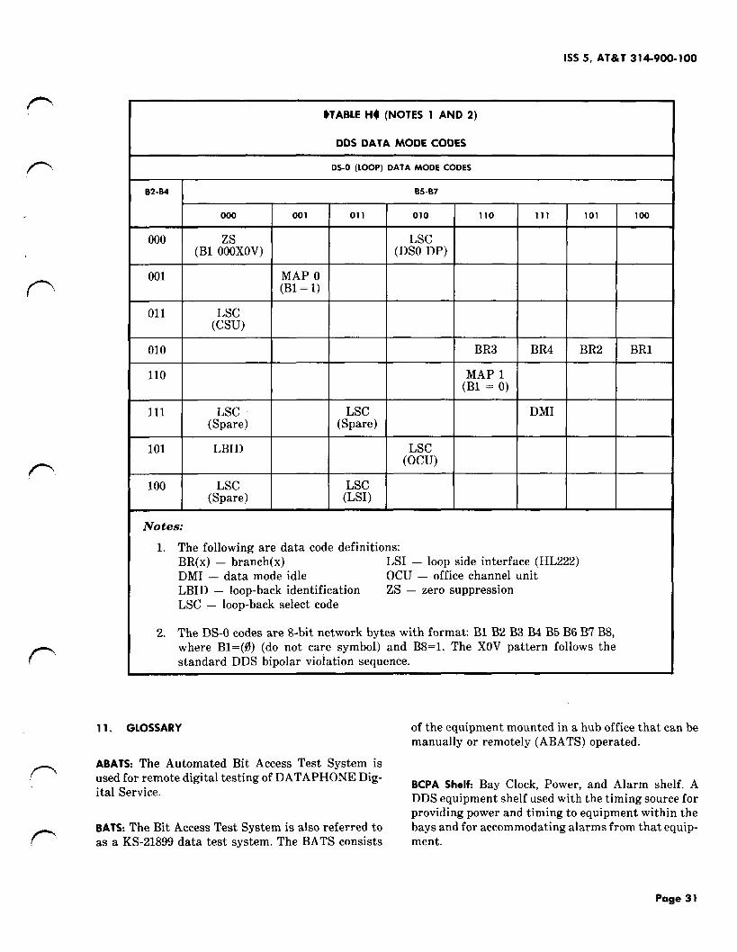
1SS 5, AT&T 314-900-100
*TABLE H4 (NOTES I AND 2)
DDS DATA MODE CODES
DS-O (LOOP) DATA MODE CODES
02-04 I 05-07
000 001 011 Olo 110 111 101 100
000 LSC(BI OZ;XOV) (DSO DP)
001 MAP O(Bl = 1)
011 LSC(Csu)
010 BR3 BR4 BR2 BR1
110 MAP 1(Bl = O)
111 LSC LSC DMI(Spare) (Spare)
101 LBID LSC(Ocu)
100 LSC LSC(Spare) (LSI)
Notes:
1. The following are data code definitions:BR(x) – branch(x) LSI – loop side interface (HL222)DMI – data mode idle OCU – office channel unitLBID – loop-back identification ZS — zero suppressionLSC – loop-back select code
2. The DS-O codes are 8-bit network bytes with format B1 B2 B3 B4 B5 B6 B7 B8,where Bl=(0) (do not care symbol) and B8=1. The XOV pattern follows thestandard DDS bipolar violation sequence.
11. GLOSSARY of the equipment mounted in a hub office that can bemanually or remotely (ABATS) operated.
ABATS: The Automated Bit Access Test System is-{’ used for remote digital testing of DATAPHONE Dig-
ital Service.BCPA Shelf: Bay Clock, Power, and Alarm shelf. ADDS equipment shelf used with the timing source forproviding-power and timing to equipment-within the
PBATS: The Blt Access Test System is also referred to bays and for accommodating alarms from that equip-as a KS-21899 data test system. The BATS consists ment.
Page 31

AT&T 314-900-100
TABLE I
REFERENCES FOR CUSTOMER STATIONARRANGEMENTS AND LOCAL LOOPS
IEOUIPMENT SECTIONS
550A-type CSU 595-100-100 (D)595-100-200 (I)595-100-300 (M)595-100-500 (T)595-100-180 (0)
500A-type DSU 595-200-100 (D)595-200-200 (I)595-200-300 (M)595-200-500 (T)595-200-180 (0)
56-kb/s regenerative 314-920-100 (D)repeater (office 314-920-300 (M)mounted) 314-920-500 (T)
56-kb/s regenerative 640-251-106 (D) (I)repeater (outside 640-251-107 (T) (M)mounted)
BPNRZ: Bipolar Nonreturn-to-Zero. A 3-level code inwhich alternate ones change sign (for example, 1011becomes +1, O, –O, +1) and in which transitions be-tween adjacent ones do not pause at the zero voltagelevel (Fig. 3B).
BPRZ: Bipolar Return-to-Zero. Same as BPNRZ ex-cept that transitions between adj scent ones pause atthe zero voltage level (Fig. 3A).
BPV: Bipolar Violation. A violation of the alternating+1, –1 pattern in a 3-level code.
Byte: In the DDS, byte refers to a group of eight con-secutive binary digits associated with a single cus-tomer.
Byte Stuffing: In the DDS, the technique by which thebit rate of a digital stream is increased by repeatingbytes and transmitting them at a faster rate. The in-formation content of the stream is not increased.
Chain: An arrangement using T1WB4S or T1WB5S, orboth, to allow a small local end office and no morethan two chain offices to share a single T1 facility.
Chain OWce: An office having a T1WB4 or T1WB5that is operated in the chained data mode.
collection Office: An office in the DDS that serves asa channel concentration point from more than oneother office. It has the equipment configuration of ahub office but does not do the hub functions. All datachannels appearing at a collection office are routedto a hub office for testing and cross-connection.
Control Signal= A signal transmitted from the masterstation to reset the DSS (data station selector), stepthe DSS to the next port, or execute a DSS controlfunction.
CP: Circuit Pack. A unit that contains part of theDDS circuitry and that can be inserted into equip-ment shelves where required.
Cross-connect: A piece of hardware used to intercon-nect line terminating equipment, multiplexer, andother equipment. Access to signals is often availablethrough jacks associated with a testboard locatednear the cross-connect.
DBM and TC: Data Base Manager and Test Controller.A central location containing minicomputers withassociated equipment. The minicomputers are desig-nated as data base manager and test controller.
DDGT: Digital Data Group Terminal. A terminal pro-viding the electrical interface between a DDS chan-nel at the DS-O level and a duplex analog group bandtransmission facility. The test controller minicom-puter has a complete backup system for continuouson-line operation.
DDS: Digital Data System. $The abbreviation DDScannot be used to represent DATAPHONE@ DigitalService.t
$DLSA: Digital LATA Serving Area is a geographicarea covering all DATAPHONE” Digital Service cus-tomer stations as defined in the Federal Communica-tions Commission Tariff.4
DOV: Data Over Voice is a technique used on digitalfacilities that derives two 1.544-Mb/s digital chan-nels from the spectrum above mastergroup 6 (19.66to 21.38 MHz) in L4 carrier systems.
DP: Dataport. A family of special channel units thatare required for the D3 and D4 channel banks when
“’n
‘-n
L
-1
‘-J
-’l
-1
Page 32

1SS 5, AT&T 314-900-100
.
f-
TABLE J
REFERENCES FOR GENERAL OFFICE EQUIPMENT
TYPE OF OFFICE
E@JIPMENT END INTERMEDIATE COLLECTION HUB SECTIONS
Ocu x x x x 314-910-100 (D)314-910-300 (M)
ISMX x x x 314-910-500 (T)
DSAU x 314-960-100 (D)314-960-300 (M)
5V power supply shelf x x x x 314-970-101 (D)
M-JCP and SM-JCP x* 314-970-100 (D)
QTP Xt 314-914-100 (D)- 314-914-300 (M)
DSX-O x x x x 314-914-400 (c)
SRDM x x 314-911-100 (D)314-911-300 (M)314-911-501 (T)314-911-502 (T)
SPM x x 314-983-110 (D)314-983-310 (M)314-983-510 (T)
TIDM x x x x 314-912-100 (D)314-912-300 (M)314-912-500 (T)
TIDM-PM x x x x 314-983-100 (D)314-983-300 (M)314-983-500 (T)
T1WB4 x x 314-915-100 (D)314-915-300 (M)314-915-501 (T)
T1WB5 x x 314-915-110 (D)314-915-310 (M)314-915-510 (T)
TIASU x x x x 365-200-104 (D)365-200-204 (I)365-200-504 (T)
DSX-1 x x x x 365-301-101 (D)
See footnote explanations at end of table.

AT&T 314-900-100
TABLE J (Contd)
REFERENCES FOR GENERAL OFFICE EQUIPMENT
TYPE OF OFFICE
EQUIPMENT END INTERMEDIATE COLLECTION HUB SECTIONS
LTS x x x 314-913-120 (D)314-913-320 (M)314-913-520 (T)
BCPA circuit x x x x 314-916-100 (D)314-916-300 (M)314-916-500 (T)
KS-20908 (receiver) x x x x 107-601-100 (D)
KS-20908 (transmitter) x x x x 107-600-100 (D)
NTS x 314-913-110 (D)314-913-310 (M)314-913-510 (T)
STS x x x 314-913-115 (D)314-913-215 (CV)314-913-315 (M)314-913-515 (T)
KS-21899 DTS x 107-605-100 (D)107-605-200 (I)107-605-300 (OPR)107-605-500 (M)
DDGT x$ x 314-918-100 (D)314-918-300 (M)
MJU x 314-917-100 (D)314-917-300 (M)314-917-500 (T)
Off-Net extension x 314-919-100 (D)
(subrate) 314-919-200 (I)314-919-300 (M)314-919-500 (T)
831A data auxiliary set x 598-083-101 (ID)
See footnote explanations at end of table.
?.
.
“n
.’q<
‘n
“-)

1SS 5, AT&T 314-900-100
f’-
/
TABLE J (Contd)
REFERENCES FOR GENERAL OFFICE EQUIPMENT
TYPE OF OFFICE
EQUIPMENT END INTERMEDIATE COLLECTION HUB SECTIONS
Dataport channel unitD3B channel bank x x x x 365-150-107 (D)D4B channel bank x x x x 365-170-120 (D)Central officeterminal $ x x x x 363-202-400 (TOP)
Remote terminal $ x x x x 363-202-401 (TOP)
* Not used in T1WB5 bay and newer TIDM bay
T Used in T1WB5 bay and TIDM bay
* Used in non-DDS end (hub) office
$ part of SLC@96 subscriber loop carrier system
used in the provision of DATAPHONE@ Digital Ser- DS-O signal for further connections. The input andvice.
pDSAU: A DS-1 Signal Access Unit that provides 1.544-Mb/s access for the ABATS.
DS-CS: Digital Signal at the Customer Service Level.A modified BPRZ signal at a customer data rate (2.4,4.8,9.6, or 56 kb/s). The bipolar format is modified bythe inclusion of bipolar violations for network con-trol.
DS-0: Digital Signal at the O level. A BPNRZ signalat the 64-kb/s rate.
f= DS-OA: A DS-O signal that carries data for only onecustomer. For subrates, customer data is byte stuffedas necessary to obtain the DS-O signal level.
DS-OB: A DS-O signal identical to a DS-OA signalwhen carrying 56-kb/s customer data, but capable of
9 carrying data from several subrate customers. Forsubrates, successive bytes carry data for different
Pcustomers so that each customer-generated bit ap-pears only once in the DS-OB signal. The DS-OB datasignals appear at the DSX-OB.
DSO DP: Digital Signal at O level dataport channel
P unit. A plug-in circuit pack that is used to recover a
output signals of the DSO DP are at the 64-kb/s rate.
DS- 1: Digital Signal at the first level is a BPRZ signalat the 1.544-Mb/s rate.
DS-2: Digital Signal at the second level is a BPRZ sig-nal at the 6.312-Mb/s rate.
DSX-0: A Digital Cross-Connect used to interconnectequipment at the DS-O level.
DSX-OA: The Digital Cross-Connect where individualcustomer circuits are cross-connected.
DSX-OB: The Digital Cross-Connect used to connectsubmultiplexed circuits to TlWB4/B5 ports and toconnect TIDM and/or TlWB4/B5 ports together forthrough or bypass circuits.
DSX-1: A Digital Cross-Connect used to interconnectlines and equipment, to provide patch capability, andto provide test access at the DS-1 level.
D-T: Driver Terminator. A circuit pack used in anOCU shelf when individual OCU outputs are requiredfrom the shelf.
Page 35

TABLE K
REFERENCES FOR TRANSMISSION
SUBJECT I SECTIONS
Customer loop 314-410-310 (M)314-410-510 (T)
DS-O facility 314-902-200 (I)
DS-1 to DS-1 314-903-300 (M)
DS-1 facility 314-903-200 (I) I
Hub identification code plan I 314-901-011 (D) I
Point-to-point and multipoint 314-901-200 (I)circuits
Overall DDS 314-900-100 (D)314-900-300 (M)
2-point and multipoint 314-901-300 (M)314-901-500 (T)
T1 line qualification 365-228-500 (T)
lA-RDT 356-454-010 (D)356-454-020 (M)356-454-lZZ (D)356-454-3ZZ (OPR)356-454-5ZZ (T)
$DTE: Digital Terminating Equipment is equipmentlocated on customer premises and is required to ter-minate the loop and provide interface leads.~
Duplex: A communications mode in which transmis-sion can occur in both directions simultaneously(sometimes referred to as full duplex).
End Office: A local office that passes on toward thehub office only those circuits that entered the officeover local loops or dataport.
Frame: Twenty-four bytes plus one framing bit (193bits) on a T1 line.
Hub Office: The main LEC (local exchange company)within a LATA. The hub office provides multiplex-ing, demultiplexing, and test access.
Idle Code: A bipolar violation sequence transmittedby the $DTE4 to show that no data is being sent overthe line by the customer.
Intermediate Office: $In a DLSA, a local office thatpasses on toward the hub office circuits that enteredit from one end office in addition to those that en-tered it over local loops.q
ISMX: Integral Subrate Multiplexer.
JCP: Jack and Connector Panel. A unit used in a localoffice to connect the various pieces of equipment andto provide test access for portable test sets (see M-JCP and SM-JCP).
@LATA: Local Access and Transport Area.4
local Loop: That portion of an individual customerchannel between the station and its associated OCUdataport channel unit.
Local Office: A DDS office concentrating on-net cus-tomer circuits into T1 streams for transmission to ahub office.
Long Haul (inter-LATA): Transmission distances typi-cally beyond 50 miles, using the lA-RDS, DOV,VIDAR 20 Mb/s, or other digital transmission sys-tems.
Loopback: A testing procedure causing a received sig-nal to be returned to its source.
LTS: Local Timing Supply. A common timing sourcefor a DDS local office. In the absence of input timinginformation, this unit has the same stability as theSTS.
Metro Office: A hub office at the lowest of three levelsin the long-haul routing hierarchy. Also referred toas a class 3 office.
M-JCP: Multiplexer Jack and Connector Panel. A jackand connector panel that gives access to the DS-OBlevel ports of a TIDM, T1WB4, or T1WB5.
MJU: Multipoint Junction Unit is a unit employed ata hub office to link together three or more segmentsof a multipoint circuit.
MTS: Master Timing Supply. A modified NTS thatreceives input timing information from the 0Master4
Page 36
1SS5, AT&T 314-900-100
preference Frequency Standard and provides thistiming information to the rest of the DDS.
Multipoint: $A customer circuit with three or moreend points.~
NTS: Nodal Timing Supply. A common timing sourcefor a DDS office. This unit is highly stable in the ab-sence of input timing information.
OCU: $An Office Channel Unit is used to terminatethe local loop and provide remote loopback features.q
OCU DP: Office Channel Unit Dataport. A plug-in cir-cuit pack that terminates the customer loop for dataspeeds of 2.4,4.8,9.6, and 56 kb/s. The OCU DP outputis put into a 64-kb/s time slot directly on the T-carrier system.
Off-Net: OAn analog location not filed forDATAPHONE@ Digital Service.4
On-Net: OAn analog location filed for DATAPHONE@Digital Service.4
PCM: Pulse Code Modulation. The process in whichanalog signals are sampled, quantized, and coded intoa digital bit stream.
QTP: Quad Terminal Panel is a panel of a DSX-O pro-viding routing of 64-kb/s DS-OB level signals to theports of a T1WB5.
$Regional Hub Office: A hub office at the highest ofthree levels in the long-haul routing hierarchy. Alsoreferred to as a class 1 office.~
$Sectional Hub ~tce: A hub office at the second ofthree levels in the long-haul routing hierarchy. Alsoreferred to as a class 2 office.~
Short Haul (lntra-LATA): Transmission distances typi-cally less than 50 miles.
Skinny Hub Office: A hub office that was originallyintended to have testing capability that was neverinstituted. It functions like an intermediate office.
Slip: A defect in timing that causes a single bitsequence of bits to be skipped or read twice.
or a
SM-JCP: Submultiplexer Jack and Connector Panel. Ajack and connector panel that gives access to DS-OAlevel signals in a local office.
SRDM: Subrate Data Multiplexer.
STS: Secondary Timing Supply. A common timingsource for a DDS office. This unit may be used in huboffices and large local offices.
Subrate: In the DDS, the 2.4-, 4.8-, and 9.6-kb/s cus-tomer data rates.
TDM: Time Division Multiplexing. The process ofcombining several lower rate digital signals into ahigher rate signal by sampling each one in order.
Testing Area: A geographic area including all DDScustomer stations that home on a single hub office.
T1 Digital line: A digital transmission line used forshort-haul work that carries data at the DS-1 (l.544-Mb/s) rate.
T 1ASU: T1 Automatic Standby Unit. A unit that mon-itors a regular T1 line and its standby T1 line. It auto-matically switches to the standby, based on thebipolar violation rate of the regular line.
T1WB4: T1 WB4 data-voice multiplexer. A piece ofequipment capable of time division multiplexing amaximum of 12 DS-OB data channels with PCM-encoded voice channels from a voice channel bankinto a DS-1 stream.
T 1WB5: T1WB5 data-voice multiplexer. A piece ofequipment capable of time division multiplexing amaximum of 23 DS-OB data channels with a TIDM atthe hub office.
VIDAR 20 Mb/s: A long-haul transmission systemthat provides 12 DS-1 channels over TD-2 radio usingDM1-2 terminals.
1A-RDS: The 1A Radio Digital System. A system thatprovides for the transmission of one DS-1 signal overa microwave radio link.
1A-RDT: The 1A Radio Digital Terminal. This is partof the lA-RDS that converts the DS-1 signal into asignal suitable for transmission over radio.
Page 37
37 Pages