Embed Size (px)
Citation preview
BELLSYSTEM PRACTICESATi%TCoStandard
SECTION 940-230-125Issue 1, March 1973
RADIO ENGINEERING
MOBILE RADIO
TRANSMISSION
AUXILIARY BASE TRANSMITTER OPERATION
CONTENTS PAGE
1. GENERAL . . . . . . . . . . .
2. APPLICATION . 0 . . . . . . . .
3. TRANSMISSION THEORY . . . . . .
A.
B.
c.
D.
E.
General . . . . . . . . . .
RF Signal Levels . . . . . . .
Radio Frequency Carrier Difference .
Modulation-Deviation Level Difference. . . . . . . . . . . . .
Audio TransmissionTime Delay . .
4. DELAY EQUALIZED AUDIO FACILITYLINEUP. . . . . . . . . . . . . . .
A. Description . . . . . . . . .
B. Procedure . . . . . . . . . .
C. Maintenance . . . . . . . .
5. SUMMARY . . . . . . . . . .
APPENDIX . . . . . . . . . . .
1. GENERAL
1
2
2
2
3
3
6
6
8
8
9
11
11
13
1.OI This section reviews the radio and land-linetransmission considerations for the design
of mobile telephone systems using an auxiliarybase transmitter(s) in addition to the maintransmitter. This arrangement may be requiredin locations where satisfactory base-to-mobilecoverage from a single transmitter is impracticaldue to limitations of available base station sites or
unfavorable terrain features. With two transmittersserving different parts of one service area it willusually be impossible to avoid some overlap ofcoverage, Where this overlap occurs, a mobilereceiver is exposed to both signals, resulting in aspecial case of cochannel interference. Thisinterference can be minimized by adhering to fivebasic criteria:
(1) The carrier frequencies of the two transmittersmust be maintained at a difference of 2 +1
Hz from each other.
(2) The transmitter land-line facilities must haveequal envelope delay distortion and absolute
delay characteristics.
(3) The transmitter land-line facilities must havesimilar amplitude response characteristics
over the frequency range 300-2400 Hz.
(4) The modulation indices of each transmittermust be identical for all levels of modulation
over the frequency range 300-2400 Hz. Thisimplies identical modulation limiter saturationand “just start to limit” points.
(5) The equi-signal area between the base stationsshould be removed from populous or heavily
traveled regions.
1.02 Cochannel interference between two FM orPM carriers of comparable intensity and
frequency will produce a beat note of the differencefrequency. If the modulation of the two transmittersdiffers as to the time domain and/or modulationindex, the receiver output will contain beatfrequencies, intermodulation, and distortion products.With voice-modulated RF carriers the output maybe garbled and the output is commonly called“hash” because the signal components producingit are not readily distinguishable. This “hash”degrades the intelligibility of the signal to varying
@ American Telephone and Telegraph Company, 1973
Printed in U.S.A. Page 1
SECTION 940-230-125
degrees depending on the relative signal fieldintensities of and degree of difference betweenthe signals producing it. In severe cases, usefulreception is impossible.
> — ---1‘ 1.03 Sirnultineous transmitter operation may be
\circumvented by using automatic transmitter
~ switching which will permit only one transmitter\ to operate at a time. Such switching is usually~ controlled by base receivers through a voting logic I‘ arrangement based on the received signal level or: signal-to-noise ratio. iThis arrangement generally ,
requires a switching system which is not available \as standard hardware.
~, _......— --- —--—---—-—...
1.04 In a system using simultaneous operationof multiple transmitters, carrier frequencies
must be maintained within several cycles of eachother to avoid annoying beat notes. Adequatetransmitter frequency stability can be achieved byusing optional high stability oscillators.
1.05 Another method of achieving carrier frequencysynchronization utilizes a centrally generated
audio tone to phase-lock the transmitter carrierfrequencies. This method has not been standardized.
-. .. —..— ——--—-1.06 The MJ/MK control terminals provide an ‘
option for controlling one auxiliary basetransmitter in addition to the main base stationtransmitter. This section, therefore, will limit itsconsideration to two-transmitter systems only,although the principles involved can be applied tosystems of more than two transmitters.
—~—— ——--.4 ,
1.07 The information and recommendations in ;this section represent current judgment on ~
a topic which is not subject to hard-and-fast rules.The section should be used as a guide with local ~conditions determining specific application. I
2. APPLICATION
2.o1 A decision to employ an auxiliary site shouldnot be made lightly, because of the attending
increase in system costs. It is important to notethat the only compensation derived is that ofenlarged coverage; traffic handling capacity is notaffected.
2.02 The FCC is concerned about indiscriminateuse of simultaneously operated transmitters.
One reason is the likely degradation of servicewhere competent attention to the technical aspects
is lacking. In view of this, applications for authorityto construct auxiliary transmitters should include ashowing not only of the need for added coveragebut also of the steps being taken to avoidtransmission impairment. FCC authority must beobtained before making any field tests of auxiliaryoperation, unless such tests are carried out underthe terms of a valid experimental license. A secondreason for concern involves Paragraph 21.513 ofthe FCC Rules regarding the location of the messagecenter for the radio system, and charges for callsplaced through the auxiliary transmitter.
2.03 Another primary consideration is that evenin a properly adjusted system, some degradation
of speech quality may be experienced in areas ofequal or near equal signal intensity. Accordingly,it is preferable that such areas not be permittedto fall where customer usage is heavy.
2.04 In situations where terrain features effectivelyisolate main and auxiliary coverage areas,
or where the region in which signals are closelyequal in intensity is inaccessible or sparsely traveled,the need for careful attention to the measuresoutlined in Part 3 is minimized.
2.05 Simultaneous operation with an MK mobiles~stem should be approached with utmost
caution. As discussed in Part 3, a principalrequirement for satisfactory reception of nearlyequal signals is very close correspondence of thetwo carrier frequencies. This is more difficult toensure at the higher frequencies of the MK system,primarily because of the threefold increase in theDoppler effect at a receiver in a moving vehicle.A car moving directly toward one transmitter anddirectly away from the other on a high speedhighway could receive signals in the 450-MHz bandwhich differ in frequency by up to 90 or 100 Hz,assuming identical transmitter frequencies. For
\, this reason alone, serious transmission impairment\ at 450 MHz is much more probable than at 150~Hz.
3. TRANSMISSION THEORY
A. General
3.01 As noted in Paragraph 1.o2, voice frequencyoutput of an FM or PM receiver may be
seriously degraded when the signals of two (ormore) simultaneously operated transmitters arereceived. The exact nature of and its effect on
Page 2
1SS1, SECTION 940-230-125
the intelligibility of the receiver output will varywith the following factors:
(a) Difference in field intensity of the RFcarriers at the receiver input
(b) Difference in frequency of the RF carriersat the receiver input
(c) Dissimilarity of modulation of the receivedsignals in the voice frequency range (300-2400
Hz)
(d) Differences in voice frequency propagationtime between the base station transmitter
land-line facilities (differences in radio propagationtime between the base stations and receiver arerelatively small, and therefore may be ignored).
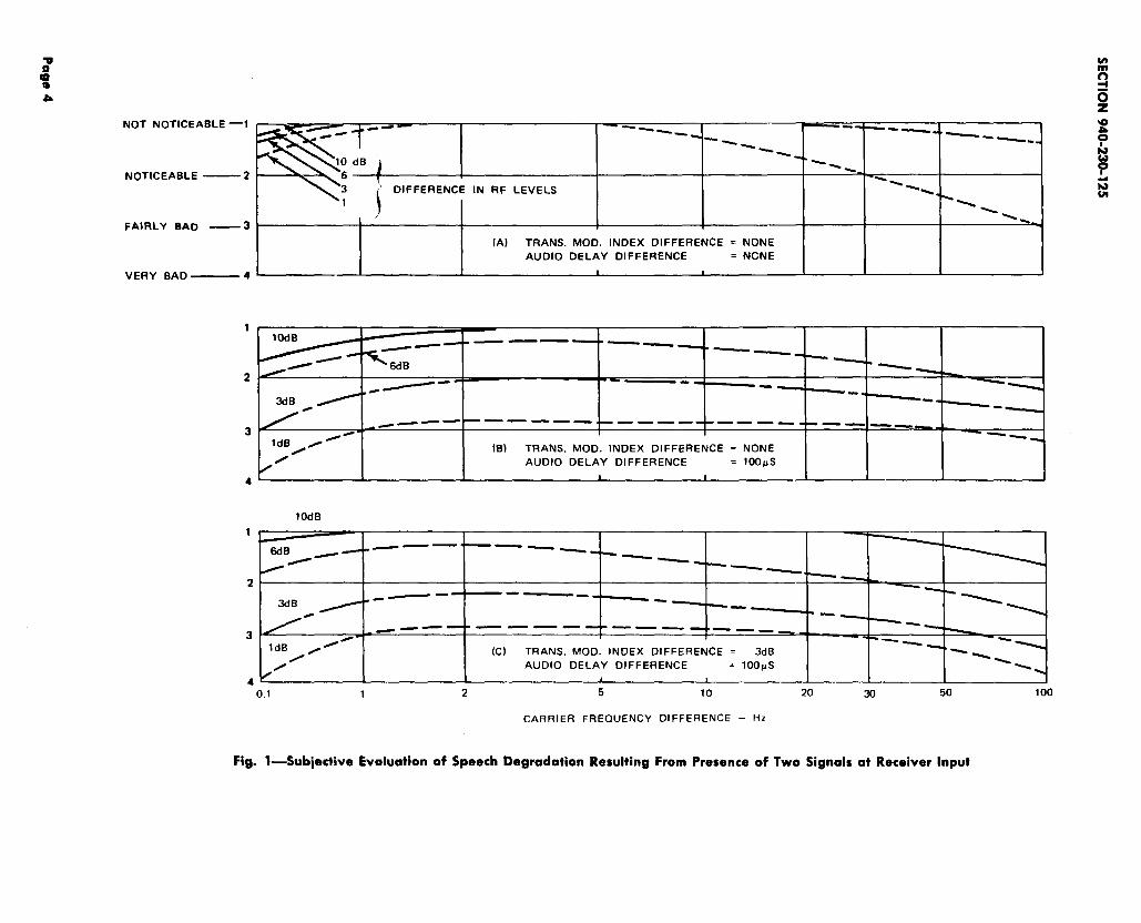
3.02 Figure 1 shows some subjective evaluationsof speech degradation caused by these factors
as observed under controlled laboratory testconditions. Judgments of impairment are plottedagainst carrier frequency difference, with relativeRF signal intensities as the variable parameter.From Fig. l(B) and l(C) it is apparent thatimpairments due to modulations index (transmittedaudio level) differences seem practically independentof those due to audio delays, and the presence ofone tends to mask the presence of the other. Nofield data is immediately available for delay equalizedaudio of different modulation indices. However,mathematical models show significant distortionintroduced at the receiver if modulation indexdifferences of greater than 2 dB exist on delayequalized signals. Therefore, if both delay andmodulation index differences exist, each must becorrected to achieve significant improvement.
3.03 The data shown by Fig. 1 are applicable ifthe mobile unit is stopped and no signal
reflecting objects in the vicinity are moving. Aircraftin flight or large van trucks moving nearby maycause fluctuations of RF amplitude and apparentreceived phase or frequency. Similar effects wouldresult if the vehicle were in motion, and may belikened to the effect seen and heard on a TV signalwhen an airplane is in the area of the receivingantenna.
mobile station normally experiences widely varyingreceived field intensities. The mobile unit is usuallyout of sight of the transmitting antenna and thesignals that get to it may travel over severaldifferent paths, each having a different attenuationand RF phase delay. The net result is a seriesof peaks and valleys as the signals over the differentpaths combine in or out of phase. Figure 2 showsa typical received signal level along 150 feet ofstreet in a relatively flat area with only lowbuildings and trees. In an urban downtown areawith various height buildings, water tanks, metalstreet light supports, etc, the magnitude of levelvariations might be on the order of two to fourtimes those shown by Fig. 2. This generally aidsauxiliary transmitter operation.
3.o5 When a second or auxiliary transmitter isadded, its RF field intensity pattern will be
similarly irregular, but not related to the maintransmitter field. Where the carrier from onetransmitter exceeds the other by about 10 dB, itwill “capture” the receiver, to the complete ornearly complete exclusion of the weaker transmittersignal. At another nearby point, perhaps two tosix feet away, the relative received power levelsof the carriers may be reversed. Either locationwould provide good quality reception, but betweenthese locations the ratio of the received powerlevels varies from 10 to 1 at the first to 1 to 10at the second. If the received power level differenceis less than 6 dB with voice modulation, audiointermodulation and distortion products are created.Signal impairment increases to a maximum wherethe two signal levels are equal.
3.06 The change in speech degradation as describedhere assumes a series of observations on a
stationary receiver at successive points. If thereceiver is in motion, even as slowly as 5 to 10mph, the distortion caused by change of levels stilloccurs, but its influence on signal degradation maybe partly or completely masked by changes in thecarrier fkquencies and the resultant beats causedby Doppler shift. Casual observation from amoving vehicle will not indicate whether the actualfault is RF level difference or frequency differenceor both.
C. Radio Frequency Carrier DifferenceB. RF Signal Levels
3.o4 In areas other than flat open country, thesignal from a single base transmitter to a
3.o7 Two carriers of identical frequencies andcomparable intensity received at a parked
mobile station could combine in phase opposition
Page 3
NOT NOTICEABLE ‘1
NOTICEABLE —2
FAIRLY BAD —--3
VERY BAD— 4
1
2
3
4
1
‘ DIFFERENCE IN RF LEVELS
L (A) TRANS. MOD. INDEX DIFFERENCE = NONEAUDIO DELAY DIFFERENCE = NGNE
I #
10dB
---- —
3dB0
ldB/0
0(B) TRANS. MOD. INDEX DIFFERENCE = NONE
10dB
6dB——— ———_
/--- -
2 . — - ..— - -—.. .
3dB/ — ~
_—— ——— —3 1
1dB RM
,0=(c) TRANS. MOD. INDEX DIFFERENCE = 3dB
AUDIO DELAY DIFFERENCE = loops
4 ~, ,
2 5 10 200.1 1
Fig. l—Subjective Evaluation
CARRIER FRECIUENCY DIFFERENCE – HZ
of Speech Degradation Resulting From Presence of Two Signals
30 50 100
at Receiver Input

1SS1, SECTION 940-230-125
+5
o
-5
-10
.—
v!.——T3dB 6dB
i——.
—— 1
Fig. 2—Variation of 152-MHz Signal Level Along Street in Relatively Level Area
producing essentially complete cancellation. If thefrequencies differ slightly, they will produce a beatnote at the difference frequency which may bedisturbing to the listener. If the frequency differenceapproaches 100 Hz, limiters or other nonlinearreceiver circuits will produce third or higher orderdistortion products. Many of these products willfall within the voice passband and, when mixedwith the desired voice frequencies, can producesevere degradation.
3.08 Transmitters maintained at a frequencydifference of 1 to 30 Hz will provide optimum
reception at a stationary receiver by preventingcomplete signal cancellation and limiting distortion.If the receiver is in motion, however, such as ina moving vehicle, the frequency received from eachtransmitter will be altered by Doppler shift, theworst case being when the direction of travel ison a straight line between transmitter sites.Doppler shift, therefore, places further constraintson transmitter carrier frequency offset.
3.o9 For example, a receiver in a vehicle traversingthe intersite path described in Paragraph
3.08 at 60 mph will experience a net Doppler shiftof about 27 Hz on the two 150-MHz signals.Therefore in order to optimize the received signalquality, transmitter carrier offset must be limitedto between 1 and 3 Hz. A reasonable criterion
for carrier frequency offset appears to be about 2Hz. Under most situations this will cause the netfrequency shift to lie within the 1-to 30-Hz limitation.
3.10 Precision frequency control of all transmittersin the system is thus required to maintain
this small (2 Hz) frequency differential. MJ basestation transmitters are available with a highstability oscillator option having a rated stabilityof 0.000005’70 or *7.5 Hz at the 150-MHz operatingfrequency. Field experience indicates that overnormal ranges of ambient temperature, the frequencystability of this precision oscillator unit is usuallybetter than +1 Hz over a 12-month period. Inview of these data, a carrier frequency differencevalue of 2 *1 Hz is suggested. It must beremembered that the objective of precision frequencycontrol in this application is not control of theabsolute frequency, but rather, control of thefrequency a!if?erencebetween the two transmitters.
3.11 Perhaps the simplest method of setting theprescribed frequency offset is to station an
observer with a receiver for the frequency beingadjusted, and some means of communications toboth transmitter sites, at a point where the fieldintensities from both transmitters are equal. Aftersetting one transmitter to the assigned frequency,both transmitters must be placed on-the-air, andthe second transmitter frequency adjusted to
Page 5
SECTION 940-230-125
produce an audible beat of 2 Hz, counted andreported by the observer. It might be wise tonote that use of precision frequency counters forthe purpose of setting the 2-Hz differential is notadvisable due to probable environmental variationsbetween base stations and the resultant possibilityof counter error, and the possible introduction ofcounter error due to counter transportation betweenlocations. Additionally, few counters will read ninesignificant figures of frequency accurately (eg,152,750,00J Hz).
3.12 With a transmitter frequency difference of2 *1 Hz, the undesired condition of zero
beat at a mobile receiver is possible only at somesingle net value of Doppler shift between 1 and 3Hz depending on the frequency difference of thetwo transmitters. This value of Doppler shiftcorresponds to some single value of the componentof vehicle velocity parallel to the intertransmittersite line of Paragraph 3.08 between 2 and 7 mph,with the direction of that vehicle velocity towardthe lower frequency transmitter. The infrequentcase of a net Doppler shift greater than 30 Hz willnot cause a sudden deterioration of signal intelligibilityin the affected mobile receiver.
D. Modulation-Deviation Level Difference
3.13 Just as intermodulation or beats betweenunmodulated carriers are inhibited by keeping
the carriers at nearly equal frequencies, themoduiati”onindex (ie, frequency deviation) of suchcarriers should be kept as nearly equal as possibleto minimize beats between modulation componentsof the signals. Control of audio modulation consistsof three steps.
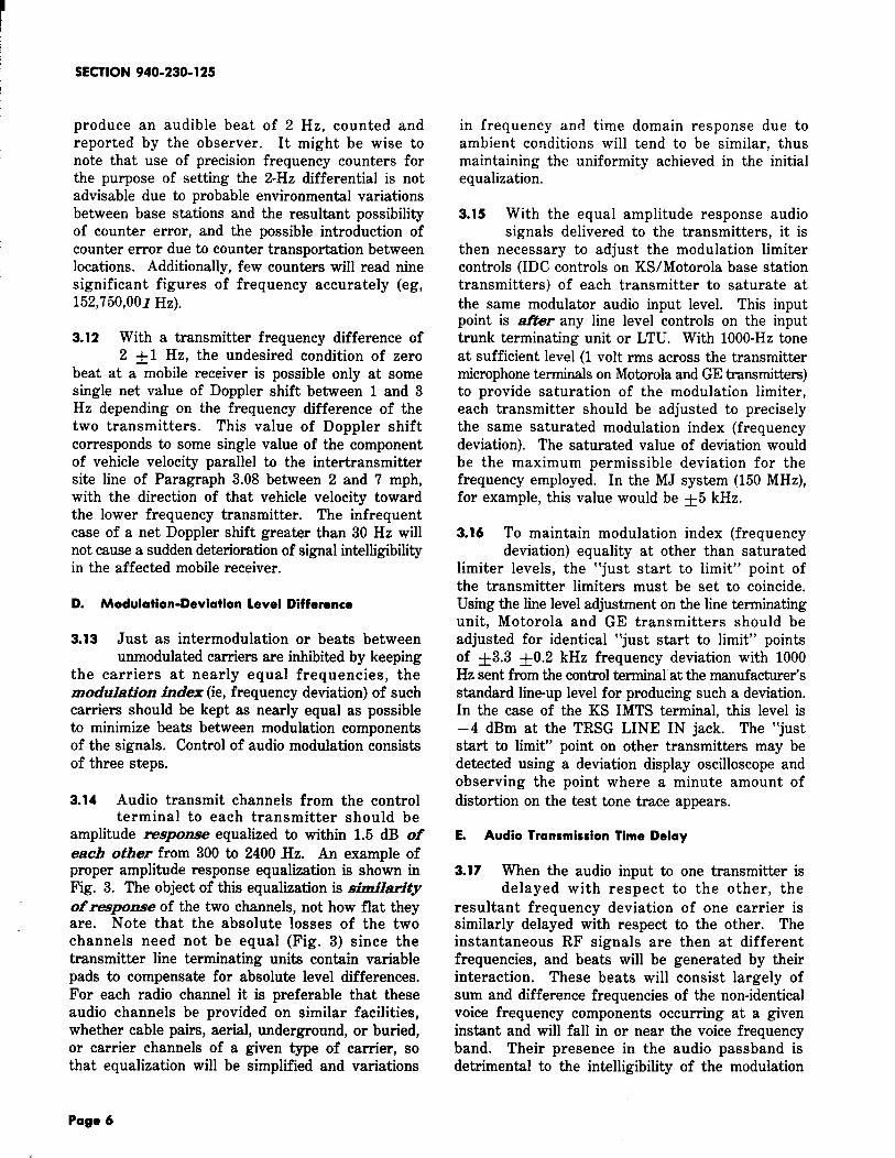
3.14 Audio transmit channels from the controlterminal to each transmitter should be
amplitude response equalized to within 1.5 dB ofeach other from 300 to 2400 Hz. An example ofproper amplitude response equalization is shown inFig. 3. The object of this equalization is sim.ilam”tyof response of the two channels, not how flat theyare. Note that the absolute losses of the twochannels need not be equal (Fig. 3) since thetransmitter line terminating units contain variablepads to compensate for absolute level differences.For each radio channel it is preferable that theseaudio channels be provided on similar facilities,whether cable pairs, aerial, underground, or buried,or carrier channels of a given type of carrier, sothat equalization will be simplified and variations
in frequency and time domain response due toambient conditions will tend to be similar, thusmaintaining the uniformity achieved in the initialequalization.
3.15 With the equal amplitude response audiosignals delivered to the transmitters, it is
then necessary to adjust the modulation limitercontrols (IDC controls on KS/Motorola base stationtransmitters) of each transmitter to saturate atthe same modulator audio input level. This inputpoint is tier any line level controls on the inputtrunk terminating unit or LTU. With 1OOO-HZtoneat sufficient level (1 volt rms across the transmittermicrophone terminals on Motorola and GE transmitters)to provide saturation of the modulation limiter,each transmitter should be adjusted to preciselythe same saturated modulation index (frequencydeviation). The saturated value of deviation wouldbe the maximum permissible deviation for thefrequency employed. In the MJ system (150 MHz),for example, this value would be +5 kHz.
3.16 To maintain modulation index (frequencydeviation) equality at other than saturated
limiter levels, the “just start to limit” point ofthe transmitter limiters must be set to coincide.Using the line level adjustment on the line terminatingunit, Motorola and GE transmitters should beadjusted for identical “just start to limit” pointsof *3.3 *0.2 kHz frequency deviation with 1000Hz sent from the control terminal at the manufacturer’sstandard line-up level for producing such a deviation.In the case of the KS IMTS terminal, this level is–4 dBm at the TRSG LINE IN jack. The “juststart to limit” point on other transmitters may bedetected using a deviation display oscilloscope andobserving the point where a minute amount ofdistortion on the test tone trace appears.
E. Audio Transmission Time Delay
3.17 When the audio input to one transmitter isdelayed with respect to the other, the
resultant frequency deviation of one carrier issimilarly delayed with respect to the other. Theinstantaneous RF signals are then at differentfrequencies, and beats will be generated by theirinteraction. These beats will consist largely ofsum and difference frequencies of the non-identicalvoice frequency components occurring at a giveninstant and will fall in or near the voice frequencyband. Their presence in the audio passband isdetrimental to the intelligibility of the modulation
Page 6

--m
o
–1
–2
–3
–4
-5
–6
-7
-8
–9
-lo
-11
–12
0 dBm SENT – – ALL FRECNJENCIES
MEASURED
RESPONSE:
FACILITY 1i
MEASURED
1000 Hz‘-–---- ––--–––-) Loss OF ‘-–-( –3.8dBm)
\’FAc’L’Ty’+
I
t
1.5dB
&\\\\\
+
MEASURED
IWO Hz.-— —
LOSS OF —
L\\\\\\\\-
— – –(–8.5dBm)FACILITY 2
Fig. 3-Measured Amplitude Response of Equalized Transmitter Land-Line Facilities
SECTION 940-230-125
transmitted and may best be subjectively classifiedas noise or hash.
3.18 Figure 1 shows a subjective evaluation of.voice frequency degradation for an audio
frequency delay difference of 100 ps. Field testsindicate that absolute delay differences of less than60 ps over the voice frequency range of 300 to2400 Hz will ensure satisfactory transmission,provided the other factors discussed in this sectionare adjusted and controlled within the limitsprescribed. Methods of achieving delay equalizationfor the transmitter audio land-line channels shouldbe discussed with the local data transmissionengineers, since the same equipment and proceduresused to delay equalize data facilities are used todelay equalize these audio channels.
3.19 It is important to note that in data applicationsit is desirable to equalize the envelope delay
distortion (ie, the delay at various frequencies oftransmission) of the data channel to provide equaldelay at all frequencies of transmission over thefacility. It is only essential, in the auxiliarytransmitter case, that the absolute delay of alltransmitter audio channels serving a given radiochannel be equal at any frequency in the audiopassband. For example, it is not necessary thatthe absolute delay of transmission of frequency“A” be equal to the absolute delay at frequency“B” on any one facility. However, it is essential
that the absolute delay of frequency “A” on facility“1” be equal to the absolute delay of frequency“A” on facility “2.” To achieve this in practiceit is necessary to cause the envelope delay distortionacross the voiceband of facility “2” to be the same(though not necessarily flat) as the envelope delaydistortion of facility “1.”* This achieved, it onlyremains to add flat delay equalization until absolutedelay is equalized at any one frequency in thevoiceband. Since the channels have the sameenvelope delay distortion, absolute delay must thenbe the same at a frequencies of interest.
3.2o In the event that J41646 series “FS” remotesignaling units are employed to permit the
use of carrier on one but fewer than all of thetransmitter audio channels, the transmission delaysintroduced by these units must be considered inthe total delay of the system. In the case of all
●As in the case of amplitude response, this is most easily
achieved if similar transmission facilities are used in each
transmitter audio channel.
audio channels having FS units, a uniform delaywill be introduced into each audio path resultingin a net difference in introduced delay of zero.
3.21 On-location testing of the delay equalizedsystem is necessary to achieve proper lineup
and system performance. The appropriate testing
and lineup procedures described in Part 4 requirepersonnel at the control terminal, each transmitterlocation, and at the same observation site used toadjust carrier offset frequencies as described inParagraph 3.11. These personnel must be deployedsimultaneously. Note, however, that measurementof only the envelope delay of the transmissionfacilities may be performed with personnel only atthe sending and receiving end of the facility undertest.
3.22 It is implicit throughout the foregoingdiscussion that transmitters with similar
modulator and multiplier stages will be used. Useof nonsimilar units would necessitate equalizationof the delay and amplitude responses of thetransmitters in addition to the connecting circuitry.It is not our intent to describe this procedure.
4. DELAY EQUALIZED AUDIO FACILITY LINEUP
A. Description
4.01 Before any attempt is made to effect theon-location testing described in Paragraph
3.21, the following steps should be completed.
(a) Determine an equal field intensity point perParagraph 3.11.
(b) Set the transmitter carrier frequency offsetsper Part 3C.
(c) Estimate the necessary absolute and envelopedelay equalization requirements for each
transmitter audio facility. Connect the delayequalization components into the various audiofacilities as estimated.
(d) Verify the equality of envelope delay timesbetween the various audio facilities. This
test should be coordinated with the data engineers.Verification of the absolute delay of the facilitiesis not possible with presently available testequipment.
Page 8
1SS1, SECTION 940-230-125
(e) Verify the various facility audio amplituderesponse characteristics per Part 3D.
(f) Set transmitter modulation controls perParagraphs 3.15 and 3.16.
4.02 Final adjustment of the system consists ofthe following steps.
(a) With field forces deployed per Paragraph3.21, the transmitter carrier frequency offset
is checked per Paragraph 3.11, and the individualtransmitter modulation indices are checked perParagraphs 3.15 and 3.16. After the offset andfrequency deviations have been ascertained tobe correct, the radio field intensity, and audiolevel as received at the equi-signal observationpoint are recorded for each transmitter in thesystem.
(b) Voice tests are made with calculated valueof delay in the circuits. The amount of
delay is changed by small increments and theaudio polarity of one station is reversed for eachvalue of delay. If the effect of the reversal isto severely degrade or attenuate the receivedaudio, the delay equalization is nearing properadjustment. Proper adjustment occurs with thebest audio “canceling” effect occurring with thereversal. For an in-depth discussion of thisprocedure, refer to Appendix A of this section
(c) The results of (b) above are logged and/orplotted to the field observation point to show
the contrast resulting from the polarity reversals.
(d) The results are then analyzed to select thatincrement of delay equalization which provided
the greatest contrast of transmission with reversalof polarity.
(e) In the event that reversal of polarity producesa better signal at the receiver, the audio
facility may have been improperly polarized.The facility should be permanently connected toprovide the best signal level and quality.
B. Procedure
4.o3 Each mobile telephone transmitter and wireline must meet normal individual transmission
requirements before any attempt is made to improvetransmission by delay equalization. Throughoutthe system, each item that affects transmission
quality must be verified. This requires that carrieroffsets are adjusted per Paragraph 3.11, andmodulation indices are equalized per Paragraphs3.15 and 3.16.
4.o4 Careful planning, coordination, and thoroughpreparation beforehand are essential; otherwise,
the transmission contrast which is sought duringthis procedure will be masked by discrepancies inthe performance of the stations and variations inthe transmission evaluations of different persons.
4.05 This procedure is based on the assumptionthat the absolute and envelope delay
characteristics have been computed, measured, andanalyzed as covered in Paragraph 4.01 and Part3E.
4.06 The following procedures should be usedfor delay equalizing the audio facilities
serving simultaneously operating transmitters inmobile telephone systems. There are two methods:(1) voice modulation and (2) tone or noise generatormodulation. Either method produces proper results,but when there are enough base stations or radiochannels to justify the necessary preparation, thesecond method produces quicker measurements.
4.o7 The following equipment is required for thisprocedure.
(a) A mobile radiotelephone unit adjusted forcorrect operation on the assigned frequency
for the system
(b) A volume indicator arranged to measureaudio output from the mobile observation
receiver
(c) An arrangement to measure the relativestrength of radio signals received at the
mobile observation receiver
(d) A tape recorder with a suitable prerecordedtape for test transmission (see Paragraph
4.13). The need for a recorded test messagedepends on the number of circuits to be equalized.
(e) Audio oscillator
(f) Noise generator equipped with a networkfor C message weighting
Page 9
SECTION 940-230-125
(g) Volume indicator arranged to measure audioinput to the system during tests at the
control terminal
(h) Two switching keys wired to reverse tipand ring conductors. Each key should be
equipped with suitable test cords for patchinginto each line circuit.
4.08 The entire procedure is directed from themobile unit which is located per Paragraph
3.11.
4.o9 At the mobile unit, the strength of thereceived radio carrier signal should be
measured during alternate operation of each individualradio base station. The mobile unit can easily bepositioned at a point where an equal signal strengthis received from each separate station by readinga microammeter connected into the first limitergrid
4.10
circuit of the FM receiver.
Regui.mmenti The mobile observation receivermust be at a location at which the samestrength carrier signal is received from eachbase station operated individually.
A 1OOO-HZtest tone is applied at the controlterminal. It should be employed at such a
level that the “just start to limit” point (seeParagraph 3.16) is achieved. Each transmittermust be operated individually and modulated bythe same test tone while the volume indicator isused to measure audio output at the mobile receiver.
4.11
Requirement: At the mobile unit, the audiooutput level from reception of each stationseparately must be the same +1 dB.
The requirements shown in Paragraphs 4.09and 4.10 must be met before ~ro~eeding
further toward delay equalization. If the audiosignals received are not approximately equal, somefault is indicated in the line circuits to each station,or in the radio transmitter, which must be corrected.
4.12 The reversing keys are patched into thetransmitter audio facilities at a point after
any level adjusting devices but before any dc loopor simplex voltages are applied.
4.13 The tape recorder is patched into the controlterminal at a point that is common to the
entire system. The prerecorded tape should includethe following.
(a) Announcement that a testis being conducted
(b) An indication of the amount of delay thatis to be used in the delay equipment. This
may be announced manually if desired.
(c) An indication of the position of the reversingkey (normal and reversed)
(d) A 10- to 15-second passage of speech and/ortone/noise material (recorded at a uniform
level) for normal and reverse positions of thekey during each step of delay value employed.
4.14 At the control point, the radio transmittersare both turned on, the tape recorder is
started, and the instructions on the tape aremonitored and followed as to the delay settingand the position of the reversing key.
4.15 At the mobile unit, the simultaneous modulationof both radio transmitters by the tape
recording is monitored and a chart or log recordis kept showing an evaluation of each transmissionin terms of received audio level contrast betweenconditions of opposite polarity. When the delay isequal for both stations, audio cancellation will occurwith reversed polarity and some reinforcement maybe noticeable with normal polarity. A contrast of10 to 20 dB can be expected from cancellation,while reinforcement will only amount to about 2or 3 dB.
4.16 Having selected the delay setting causingbest cancellation, a test for voice quality
and clarity is made by having someone speak tothe mobile observation unit. A small readjustmentof delay values may produce more favorable resultsin which case the readjusted value should beretained.
4.17 If cancellation occurred in the normal positionof the reversing key, then the audio input
lead to the radio transmitter at one of the stationsbeing equalized should be reversed to make thepolarity normal throughout the system.
4.18 When all wiring is completed, a further testis made with voice modulation of both
transmitters from the control point while the mobileunit is driven through the entire area of interaction
Page 10
1SS1, SECTION 940-230-125
between the adjacent stations for overall evaluationof the results.
4.19 The value of delay that is used during thesetests should cover at least 50 microseconds
above and below the point of maximum contrast,so that the test can be carried through to selectthe delay increment that is nearest to the centerof several increments which provide a contrast witha change in polarity.
4.20 Whenever a good contrast or polarity effectis not detected, a larger increment of delay
such as 100 microseconds should be used.
4.21 After changing delay by a major incrementas in Paragraph 4.20, the steps covered in
Paragraphs 4.13 through 4.16 are repeated asnecessary until the correct setting produces anunmistakable contrast with a change in polarity.
4.22 When using tones as a modulation medium,care must be exercised so as not to set the
delay equalizers where, although proper reactionis obtained from the given tone, the voice band isnot delay equalized. Proper performance may bestbe ascertained by performing the test with asecond, nonharmonically related tone.
C. Maintenance
4.23 To provide the necessary facility maintenancerecords, the envelope delay characteristics
of each line that has been delay equalized mustbe recorded in a suitable form (for example, thatshown in Fig. 4). This information should beretained with the circuit layout card.
4.24 Circuit order work which causes changes inthe delay or in the polarity of the audio line
will immediately degrade transmission to mobileunits in the area between base stations. Degradationof quality may also be due to changes or aging inthe radio equipment and associated audio modulationcircuits. To keep maintenance expense at aminimum, circuit order work must be coordinatedwith the radio engineers so that the effects ofrearrangement of facilities can be evaluatedbeforehand. If the facilities are changed for anyreason, complete realignment of the delay equalizationshould be effected.
4.25 Routine tests for satisfactory delay equalizationshould be scheduled at intervals of three to
six months, depending on local seasonal temperaturevariation—the greater the temperature variation,the lesser the interval. An observer in a mobileunit should check the equalization using much ofthe same procedure as during the delay equipmentlineup above, except that no adjustments are madein the delay equipment during these tests.
4.26 Routine tests should be made throughoutthe equi-signal interaction area. A strong
contrast is expected to result when the polarityof the audio circuit to one of the transmitters istemporarily reversed during a test call. As longas reversed polarity makes transmission obw”ouslyworse for voice messages than normal polarity,the delay equalization may be considered to besatisfactory.
4.27 No unauthorized changes should be made inthe adjustment of the delay equipment. The
performance of all circuit elements should be verifiedand any required delay readjustments should bereconciled before delay equalized circuits arerearranged.
5. SUMMARY
5.01 Simultaneous operation of two base transmittersin a mobile system will usually be satisfactory
if the system is maintained as follows.
(a) Transmitter carrier frequencies to differ by2 ~ 1 Hz, using high precision oscillators
(b) Relative audio amplitude response characteristicsof audio channels from control terminal to
each transmitter should be within 1.5 dB of eachother from 300 to 2400 Hz.
(c.) Absolute delay characteristics of channelsfrom control terminal to each transmitter
should be within 60 microseconds of each otherfrom 300 to 2400 Hz. Proper lineup is describedin Part 4B of this section.
(d) Maximum frequency deviation and “just startto limit points” of each transmitter at 1000
Hz to be as close to coincidental as possible.
(e) Periodic tests per Part 4C are effected todetect system degradation.
Page 11

SECTION 940-230-125
5.o2 The values of frequency, levels, and delay but they can readily be met with available hardware.prescribed herein are largely empirical, based There would be little if any economic gain obtainable
on limited observations in the field and in the by relaxing objectives from the prescribed limits.laboratory. Future experience may indicate thatsome limits are more restrictive than necessary,
CIRCUIT LAYOUT RECORD OF ENVELOPE DELAY
THE FOLLOWING DATA SHOULD BE RETAINCO WITH THE CIRCUIT LAYOUT LINE CARO.
RADIO LINE NUNSER: Co. OATE:
OELAY INFORMATION
2.0
00 5 10 Is 20 25
FR[QUENCY - HUNDREDSOf HERTZ
LINE (2)EWIP (3)FAC TOTALOLY NTWK
SYS DES VALSEAS VAR
NOTES:1. AT 1000 CYCLES2. I NCL CARRIER TERMS3. INCL RPTRS, COILS,
FLTRS, EGLZRS,
L I NE EQUALIZERS:
LOCAL DCLAY NTWX:
CALC (1 ) ACTUAL
ETC.
Fig. 4-Circuit Layout Record of Envelope Delay
Page 12
1SS1, SECTION 940-230-125
APPENDIXAUDIO SIGNAL POLARITY EFFECTS
A.01 Facility design requirements as outlined inPart 3E are directed toward providing equal
audio signals. These signals should produce identicalmodulation simultaneously at both stations. Thiscan be accomplished by adjusting lines to eachstation to equal relative loss and by building outeach line to provide equal delay. A similar envelopepattern must be provided across the voice-frequencyband. Once this is done, the modulation at eachradio station should be identical and simultaneous.Reversing the tip and ring conductors (audio signalpolarity) at one of the adjacent stations shouldproduce an effect at each station that is directlyopposite and simultaneous.
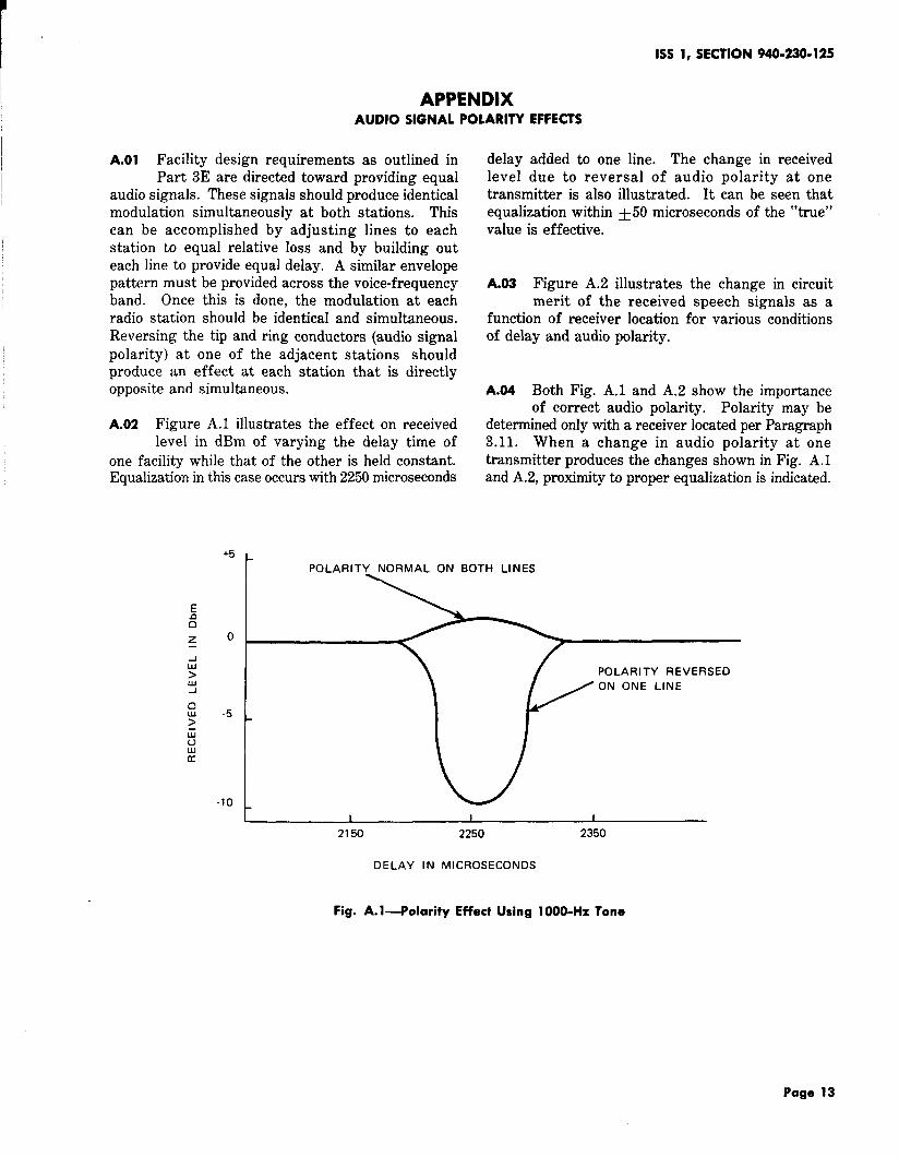
A.02 Figure A.1 illustrates the effect on receivedlevel in dBm of varying the delay time of
one facility while that of the other is held constant.Equalization in this case occurs with 2250 microseconds
delay added to one line. The change in receivedlevel due to reversal of audio polarity at onetransmitter is also illustrated. It can be seen thatequalization within *5O microseconds of the “true”value is effective.
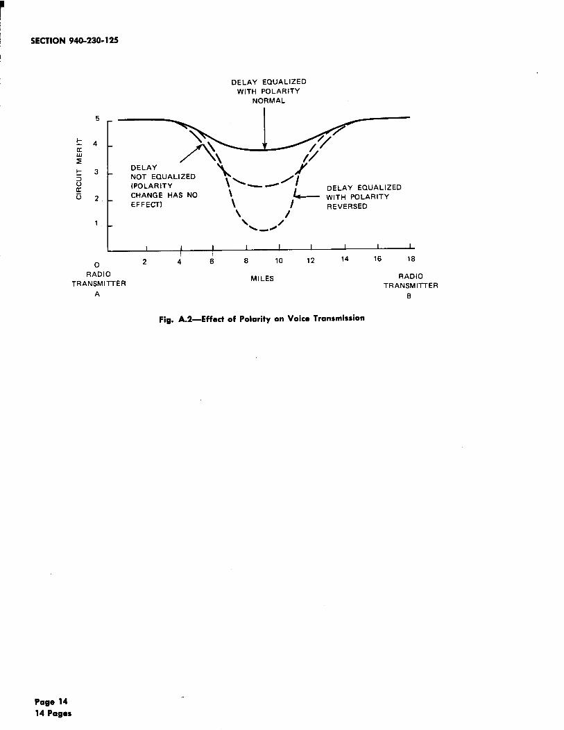
A.03 Figure A.2 illustrates the change in circuitmerit of the received speech signals as a
function of receiver location for various conditionsof delay and audio polarity.
A.04 Both Fig. A.1 and A.2 show the importanceof correct audio polarity. Polarity may be
determined only with a receiver located per Paragraph3.11. When a change in audio polarity at onetransmitter produces the changes shown in Fig. A. 1and A.2, proximity to proper equalization is indicated.
z
+5
POLARITY NORMAL ON BOTH LINES
o
POLARITY REVERSED
ON ONE LINE
-5
-lo rI I I 1
2150 2250 2350
DELAY IN MICROSECONDS
Fig. A. l—Polarity Effect Using 1000-Hz Tone
Page 13
ISECTION 940-230-125
DELAY ECNJALIZED
WITH POLARITY
NORMAL
5
\\~4
K
>
vwz
DELAY\
\~3
NOT EQUALIZED3\\~_ /
:(POLARITY
52 CHANGE HAS NO
EFFECT) \ /
\1 \\ /)
-~
DELAY EQUALIZED
WITH POLARITY
REVERSED
I I 1I 1 1 I I I I
o 2 4 6 8 10 12 14 16 18
RADIO
TRANSMITTERMILES RADIO
ATRANSMITTER
8
Fig. A.2—Effect of Polarity on Voice Transmission
Page 14
14 Pages


![Intertenancy Barrier Systems for Terrace Homes - GIB® · — Cost effective. ... Appraisal No.940 [2016] Appraisal No.940 [2016] Appraisal No.940 ... Intertenancy Barrier Systems](https://img.pdfslide.us/doc/110x75/5adfc64f7f8b9a8f298d5c1f/intertenancy-barrier-systems-for-terrace-homes-gib-cost-effective-appraisal.jpg)