Embed Size (px)
Citation preview

Printed in U.S.A. 981−0158C
10−01
KVC
The engine exhaust from this productcontains chemicals known to the State
of California to cause cancer, birth defects or other reproductive harm.
! !
gasoline warnings
1
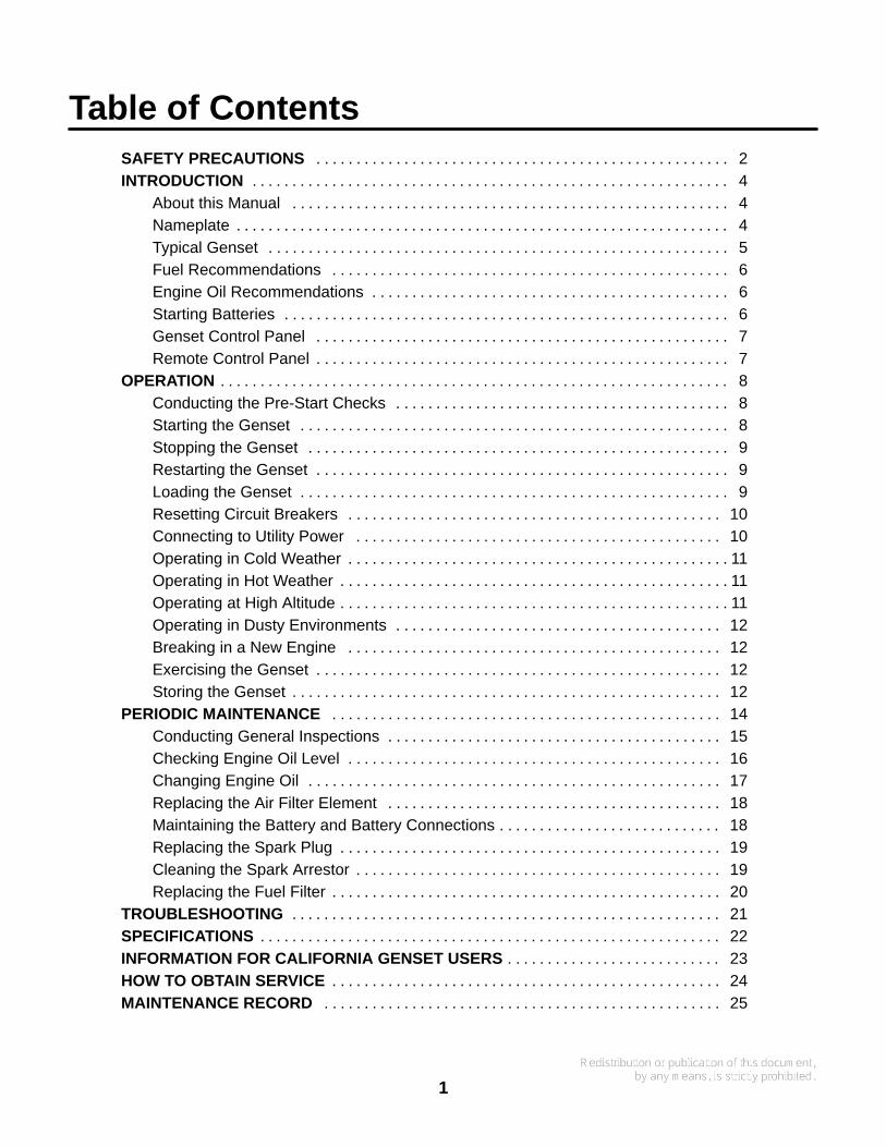
Table of ContentsSAFETY PRECAUTIONS 2. . . . . . . . . . . . . . . . . . . . . . . . . . . . . . . . . . . . . . . . . . . . . . . . . . . . INTRODUCTION 4. . . . . . . . . . . . . . . . . . . . . . . . . . . . . . . . . . . . . . . . . . . . . . . . . . . . . . . . . . . .
About this Manual 4. . . . . . . . . . . . . . . . . . . . . . . . . . . . . . . . . . . . . . . . . . . . . . . . . . . . . . . Nameplate 4. . . . . . . . . . . . . . . . . . . . . . . . . . . . . . . . . . . . . . . . . . . . . . . . . . . . . . . . . . . . . . Typical Genset 5. . . . . . . . . . . . . . . . . . . . . . . . . . . . . . . . . . . . . . . . . . . . . . . . . . . . . . . . . . Fuel Recommendations 6. . . . . . . . . . . . . . . . . . . . . . . . . . . . . . . . . . . . . . . . . . . . . . . . . . Engine Oil Recommendations 6. . . . . . . . . . . . . . . . . . . . . . . . . . . . . . . . . . . . . . . . . . . . . Starting Batteries 6. . . . . . . . . . . . . . . . . . . . . . . . . . . . . . . . . . . . . . . . . . . . . . . . . . . . . . . . Genset Control Panel 7. . . . . . . . . . . . . . . . . . . . . . . . . . . . . . . . . . . . . . . . . . . . . . . . . . . . Remote Control Panel 7. . . . . . . . . . . . . . . . . . . . . . . . . . . . . . . . . . . . . . . . . . . . . . . . . . . .
OPERATION 8. . . . . . . . . . . . . . . . . . . . . . . . . . . . . . . . . . . . . . . . . . . . . . . . . . . . . . . . . . . . . . . . Conducting the Pre-Start Checks 8. . . . . . . . . . . . . . . . . . . . . . . . . . . . . . . . . . . . . . . . . . Starting the Genset 8. . . . . . . . . . . . . . . . . . . . . . . . . . . . . . . . . . . . . . . . . . . . . . . . . . . . . . Stopping the Genset 9. . . . . . . . . . . . . . . . . . . . . . . . . . . . . . . . . . . . . . . . . . . . . . . . . . . . . Restarting the Genset 9. . . . . . . . . . . . . . . . . . . . . . . . . . . . . . . . . . . . . . . . . . . . . . . . . . . . Loading the Genset 9. . . . . . . . . . . . . . . . . . . . . . . . . . . . . . . . . . . . . . . . . . . . . . . . . . . . . . Resetting Circuit Breakers 10. . . . . . . . . . . . . . . . . . . . . . . . . . . . . . . . . . . . . . . . . . . . . . . Connecting to Utility Power 10. . . . . . . . . . . . . . . . . . . . . . . . . . . . . . . . . . . . . . . . . . . . . . Operating in Cold Weather 11. . . . . . . . . . . . . . . . . . . . . . . . . . . . . . . . . . . . . . . . . . . . . . . . Operating in Hot Weather 11. . . . . . . . . . . . . . . . . . . . . . . . . . . . . . . . . . . . . . . . . . . . . . . . . Operating at High Altitude 11. . . . . . . . . . . . . . . . . . . . . . . . . . . . . . . . . . . . . . . . . . . . . . . . . Operating in Dusty Environments 12. . . . . . . . . . . . . . . . . . . . . . . . . . . . . . . . . . . . . . . . . Breaking in a New Engine 12. . . . . . . . . . . . . . . . . . . . . . . . . . . . . . . . . . . . . . . . . . . . . . . Exercising the Genset 12. . . . . . . . . . . . . . . . . . . . . . . . . . . . . . . . . . . . . . . . . . . . . . . . . . . Storing the Genset 12. . . . . . . . . . . . . . . . . . . . . . . . . . . . . . . . . . . . . . . . . . . . . . . . . . . . . .
PERIODIC MAINTENANCE 14. . . . . . . . . . . . . . . . . . . . . . . . . . . . . . . . . . . . . . . . . . . . . . . . . Conducting General Inspections 15. . . . . . . . . . . . . . . . . . . . . . . . . . . . . . . . . . . . . . . . . . Checking Engine Oil Level 16. . . . . . . . . . . . . . . . . . . . . . . . . . . . . . . . . . . . . . . . . . . . . . . Changing Engine Oil 17. . . . . . . . . . . . . . . . . . . . . . . . . . . . . . . . . . . . . . . . . . . . . . . . . . . . Replacing the Air Filter Element 18. . . . . . . . . . . . . . . . . . . . . . . . . . . . . . . . . . . . . . . . . . Maintaining the Battery and Battery Connections 18. . . . . . . . . . . . . . . . . . . . . . . . . . . . Replacing the Spark Plug 19. . . . . . . . . . . . . . . . . . . . . . . . . . . . . . . . . . . . . . . . . . . . . . . . Cleaning the Spark Arrestor 19. . . . . . . . . . . . . . . . . . . . . . . . . . . . . . . . . . . . . . . . . . . . . . Replacing the Fuel Filter 20. . . . . . . . . . . . . . . . . . . . . . . . . . . . . . . . . . . . . . . . . . . . . . . . .
TROUBLESHOOTING 21. . . . . . . . . . . . . . . . . . . . . . . . . . . . . . . . . . . . . . . . . . . . . . . . . . . . . . SPECIFICATIONS 22. . . . . . . . . . . . . . . . . . . . . . . . . . . . . . . . . . . . . . . . . . . . . . . . . . . . . . . . . . INFORMATION FOR CALIFORNIA GENSET USERS 23. . . . . . . . . . . . . . . . . . . . . . . . . . . HOW TO OBTAIN SERVICE 24. . . . . . . . . . . . . . . . . . . . . . . . . . . . . . . . . . . . . . . . . . . . . . . . . MAINTENANCE RECORD 25. . . . . . . . . . . . . . . . . . . . . . . . . . . . . . . . . . . . . . . . . . . . . . . . . .
2
Safety PrecautionsThoroughly read the OPERATOR’S MANUALbefore operating the genset. Safe operation andtop performance can be obtained only whenequipment is operated and maintained properly.
The following symbols in this manual alert you to po-tential hazards to the operator, service person andequipment.
alerts you to an immediate hazardwhich will result in severe personal injury ordeath.
WARNING alerts you to a hazard or unsafepractice which can result in severe personal in-jury or death.
CAUTION alerts you to a hazard or unsafepractice which can result in personal injury orequipment damage.
Electricity, fuel, exhaust, moving parts and batteriespresent hazards which can result in severe personalinjury or death.
GENERAL PRECAUTIONS
• Keep children away from the genset.
• Do not use evaporative starting fluids. They arehighly explosive.
• To prevent accidental or remote starting whileworking on the genset, disconnect the nega-tive (- ) battery cable at the battery.
• Keep the genset and its compartment clean.Excess oil and oily rags can catch fire. Dirt andgear stowed in the compartment can restrictcooling air.
• Make sure all fasteners are secure and torquedproperly.
• Do not work on the genset when mentally orphysically fatigued or after consuming alcoholor drugs.
• You must be trained and experienced to makeadjustments while the genset is running—hot,moving or electrically live parts can cause se-vere personal injury or death.
• Used engine oil has been identified by somestate and federal agencies as causing canceror reproductive toxicity. Do not ingest, inhale, orcontact used oil or its vapors.
• Benzene and lead in some gasolines havebeen identified by some state and federalagencies as causing cancer or reproductivetoxicity. Do not to ingest, inhale or contact gaso-line or its vapors.
• Keep multi-class ABC fire extinguishers handy.Class A fires involve ordinary combustible ma-terials such as wood and cloth; Class B fires,combustible and flammable liquid fuels andgaseous fuels; Class C fires, live electricalequipment. (ref. NFPA No. 10)
• Genset installation and operation must complywith all applicable local, state and federal codesand regulations.
GENERATOR VOLTAGE IS DEADLY!
• Generator electrical output connections mustbe made by a trained and experienced electri-cian in accordance with applicable codes.
• The genset must not be connected to shorepower or to any other source of electrical pow-er. Back-feed to shore power can cause electricshock resulting in severe personal injury ordeath and damage to equipment. An approvedswitching device must be used to prevent inter-connections.
• Use caution when working on live electricalequipment. Remove jewelry, make sure cloth-ing and shoes are dry, stand on a dry woodenplatform or rubber insulating mat and use toolswith insulated handles.
3
ENGINE EXHAUST IS DEADLY!
• Learn the symptoms of carbon monoxide poi-soning in this manual and never sleep in the ve-hicle while the genset is running unless the ve-hicle is equipped with a working carbon monox-ide detector.
• The exhaust system must be installed in accor-dance with the genset Installation Manual. En-gine cooling air must not be used for heating theworking or living space or compartment.
• Inspect for exhaust leaks at every startup andafter every eight hours of running.
• Make sure there is ample fresh air when operat-ing the genset in a confined area.
FUEL IS FLAMMABLE AND EXPLOSIVE
• Do not smoke or turn electrical switches ON orOFF where fuel fumes are present or in areassharing ventilation with fuel tanks or equip-ment. Keep flame, sparks, pilot lights, arc-pro-ducing equipment and switches and all othersources of ignition well away.
• Fuel lines must be secured, free of leaks andseparated or shielded from electrical wiring.
• Leaks can lead to explosive accumulations ofgas. Natural gas rises when released and canaccumulate under hoods and inside housingsand buildings. LPG sinks when released andcan accumulate inside housings and base-ments and other below-grade spaces. Preventleaks and the accumulation of gas.
BATTERY GAS IS EXPLOSIVE
• Wear safety glasses.
• Do not smoke.
• To reduce arcing when disconnecting or recon-necting battery cables, always disconnect thenegative (- ) battery cable first and reconnect itlast.
MOVING PARTS CAN CAUSE SEVEREPERSONAL INJURY OR DEATH
• Do not wear loose clothing or jewelry near mov-ing parts such as PTO shafts, fans, belts andpulleys.
• Keep hands away from moving parts.
• Keep guards in place over fans, belts, pulleys,and other moving parts.
MOBILE 7
4
IntroductionABOUT THIS MANUAL
This manual covers the operation and maintenanceof the KVC series of generator sets (gensets). Eachoperator should study this manual carefully and ob-serve all of its instructions and safety precautions.Keep this manual and the Installation Manual withthe other vehicle manuals.
Operation, Periodic Maintenance and Trouble-shooting provide the instructions necessary for op-erating the genset and maintaining it at top perfor-mance. The owner is responsible for performingmaintenance in accordance with the PERIODICMAINTENANCE SCHEDULE (Page 14). Thismanual also includes genset specifications, infor-mation on how to obtain service and information forCalifornia users.
WARNING This genset is not a life support sys-tem. It can stop without warning. Children, per-sons with physical or mental limitations, andpets could suffer personal injury or death. A per-sonal attendant, redundant power or an alarmsystem must be used if genset operation is criti-cal.
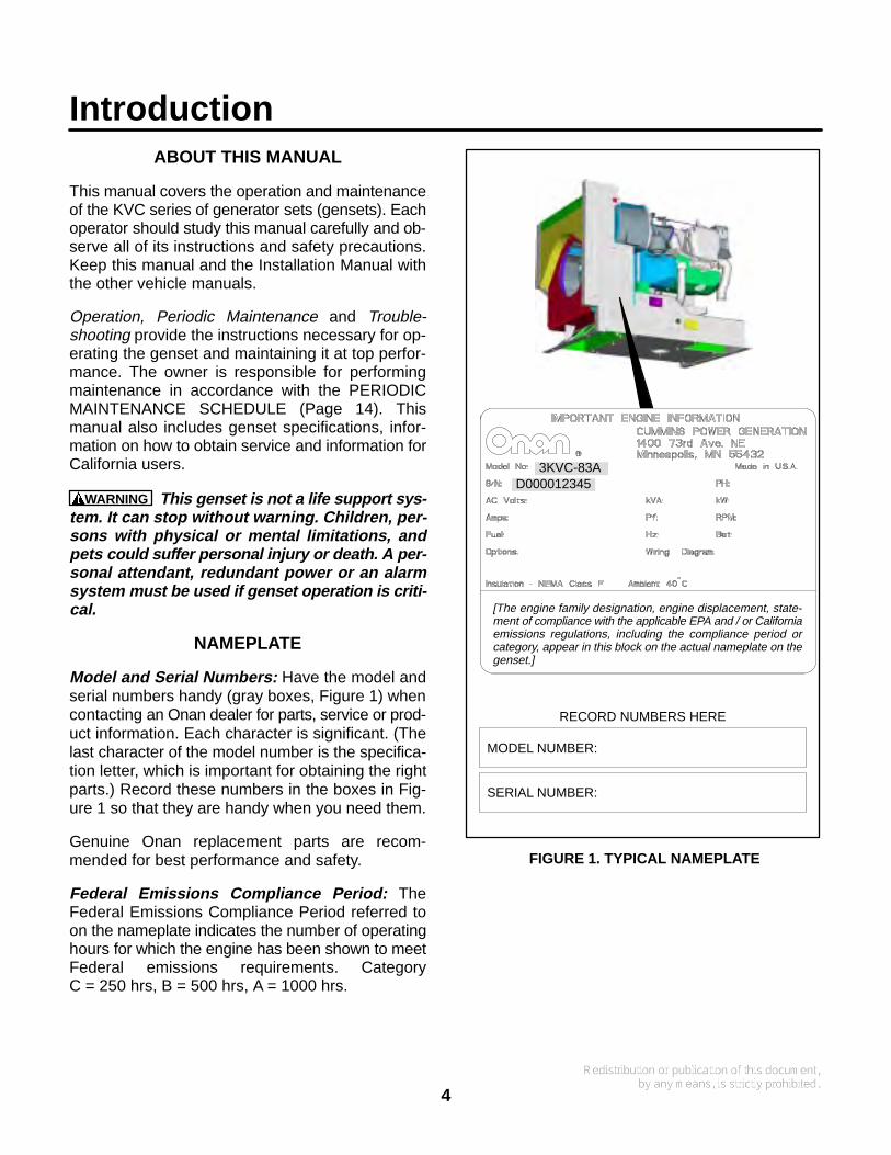
NAMEPLATE
Model and Serial Numbers: Have the model andserial numbers handy (gray boxes, Figure 1) whencontacting an Onan dealer for parts, service or prod-uct information. Each character is significant. (Thelast character of the model number is the specifica-tion letter, which is important for obtaining the rightparts.) Record these numbers in the boxes in Fig-ure 1 so that they are handy when you need them.
Genuine Onan replacement parts are recom-mended for best performance and safety.
Federal Emissions Compliance Period: TheFederal Emissions Compliance Period referred toon the nameplate indicates the number of operatinghours for which the engine has been shown to meetFederal emissions requirements. CategoryC = 250 hrs, B = 500 hrs, A = 1000 hrs.
RECORD NUMBERS HERE
MODEL NUMBER:
SERIAL NUMBER:
3KVC-83AD000012345
[The engine family designation, engine displacement, state-ment of compliance with the applicable EPA and / or Californiaemissions regulations, including the compliance period orcategory, appear in this block on the actual nameplate on thegenset.]
FIGURE 1. TYPICAL NAMEPLATE
5
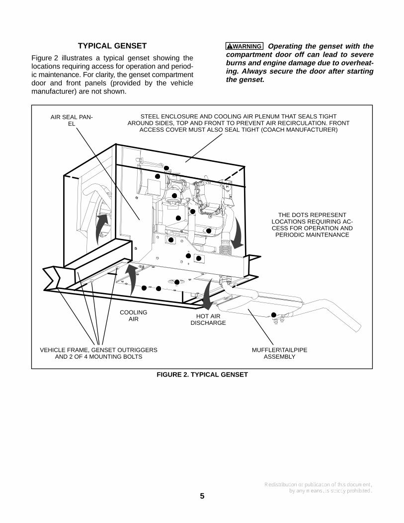
TYPICAL GENSET
Figure 2 illustrates a typical genset showing thelocations requiring access for operation and period-ic maintenance. For clarity, the genset compartmentdoor and front panels (provided by the vehiclemanufacturer) are not shown.
WARNING Operating the genset with thecompartment door off can lead to severeburns and engine damage due to overheat-ing. Always secure the door after startingthe genset.
COOLINGAIR HOT AIR
DISCHARGE
MUFFLER\TAILPIPEASSEMBLY
STEEL ENCLOSURE AND COOLING AIR PLENUM THAT SEALS TIGHTAROUND SIDES, TOP AND FRONT TO PREVENT AIR RECIRCULATION. FRONT
ACCESS COVER MUST ALSO SEAL TIGHT (COACH MANUFACTURER)
AIR SEAL PAN-EL
THE DOTS REPRESENTLOCATIONS REQUIRING AC-CESS FOR OPERATION AND
PERIODIC MAINTENANCE
VEHICLE FRAME, GENSET OUTRIGGERSAND 2 OF 4 MOUNTING BOLTS
FIGURE 2. TYPICAL GENSET
6
FUEL RECOMMENDATIONS
WARNING Gasoline is highly flammable andexplosive and can cause severe personal injuryor death. Do not smoke or turn electricalswitches ON or OFF where fuel fumes, tanks orequipment are present or in areas sharing ven-tilation. Keep flame, sparks, pilot lights, arc-pro-ducing equipment and switches and all othersources of ignition well away. Keep a type ABCfire extinguisher in the vehicle.
Use clean, fresh unleaded gasoline having a mini-mum octane rating (Anti-Knock Index) of 87.
Leaded gasoline may be used but will result in theextra maintenance required for removing combus-tion chamber and spark plug deposits. Do not usegasoline or gasoline additives (de-icers) containingmethanol because methanol can be corrosive tofuel system components.
CAUTION Do not use gasoline or gasoline ad-ditives containing methanol because methanolcan be corrosive to fuel system components.
Avoid using highly leaded gasolines and leadadditives because of the extra engine mainte-nance that will be required.
ENGINE OIL RECOMMENDATIONS
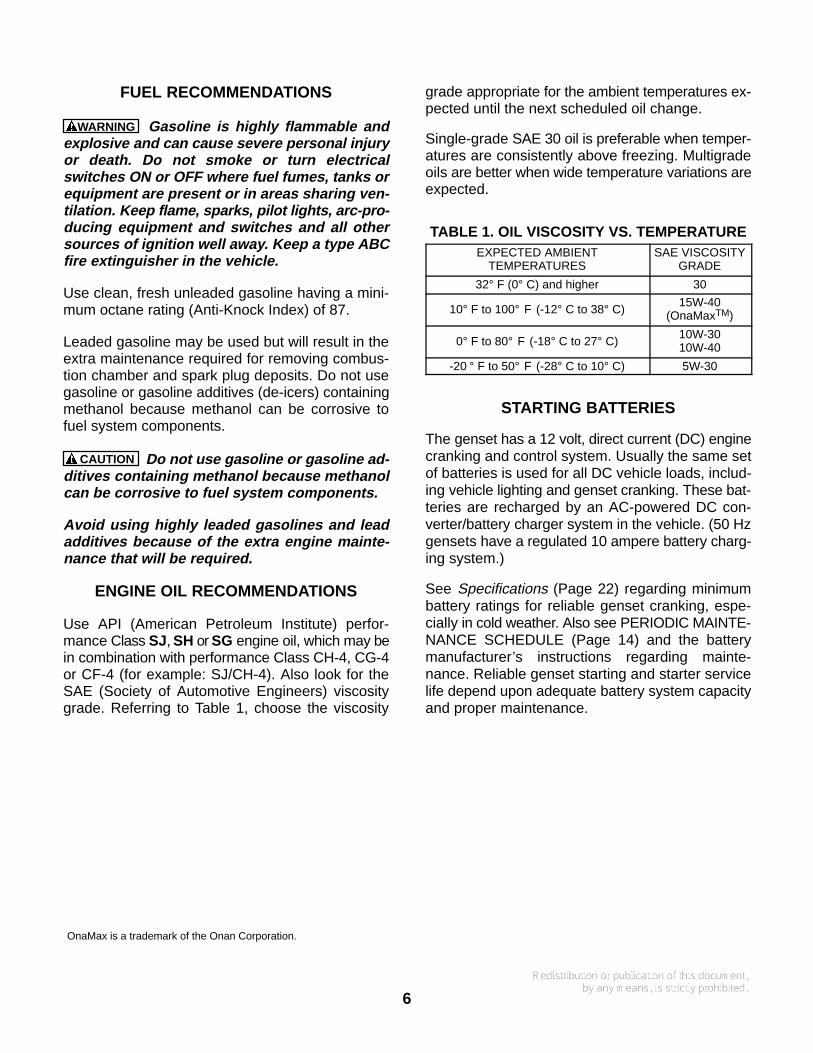
Use API (American Petroleum Institute) perfor-mance Class SJ, SH or SG engine oil, which may bein combination with performance Class CH-4, CG-4or CF-4 (for example: SJ/CH-4). Also look for theSAE (Society of Automotive Engineers) viscositygrade. Referring to Table 1, choose the viscosity
grade appropriate for the ambient temperatures ex-pected until the next scheduled oil change.
Single-grade SAE 30 oil is preferable when temper-atures are consistently above freezing. Multigradeoils are better when wide temperature variations areexpected.
TABLE 1. OIL VISCOSITY VS. TEMPERATUREEXPECTED AMBIENT
TEMPERATURESSAE VISCOSITY
GRADE
32° F (0° C) and higher 30
10° F to 100° F (-12° C to 38° C)15W-40
(OnaMaxTM)
0° F to 80° F (-18° C to 27° C)10W-3010W-40
-20 ° F to 50° F (-28° C to 10° C) 5W-30
STARTING BATTERIES
The genset has a 12 volt, direct current (DC) enginecranking and control system. Usually the same setof batteries is used for all DC vehicle loads, includ-ing vehicle lighting and genset cranking. These bat-teries are recharged by an AC-powered DC con-verter/battery charger system in the vehicle. (50 Hzgensets have a regulated 10 ampere battery charg-ing system.)
See Specifications (Page 22) regarding minimumbattery ratings for reliable genset cranking, espe-cially in cold weather. Also see PERIODIC MAINTE-NANCE SCHEDULE (Page 14) and the batterymanufacturer’s instructions regarding mainte-nance. Reliable genset starting and starter servicelife depend upon adequate battery system capacityand proper maintenance.
OnaMax is a trademark of the Onan Corporation.
7
GENSET CONTROL PANEL
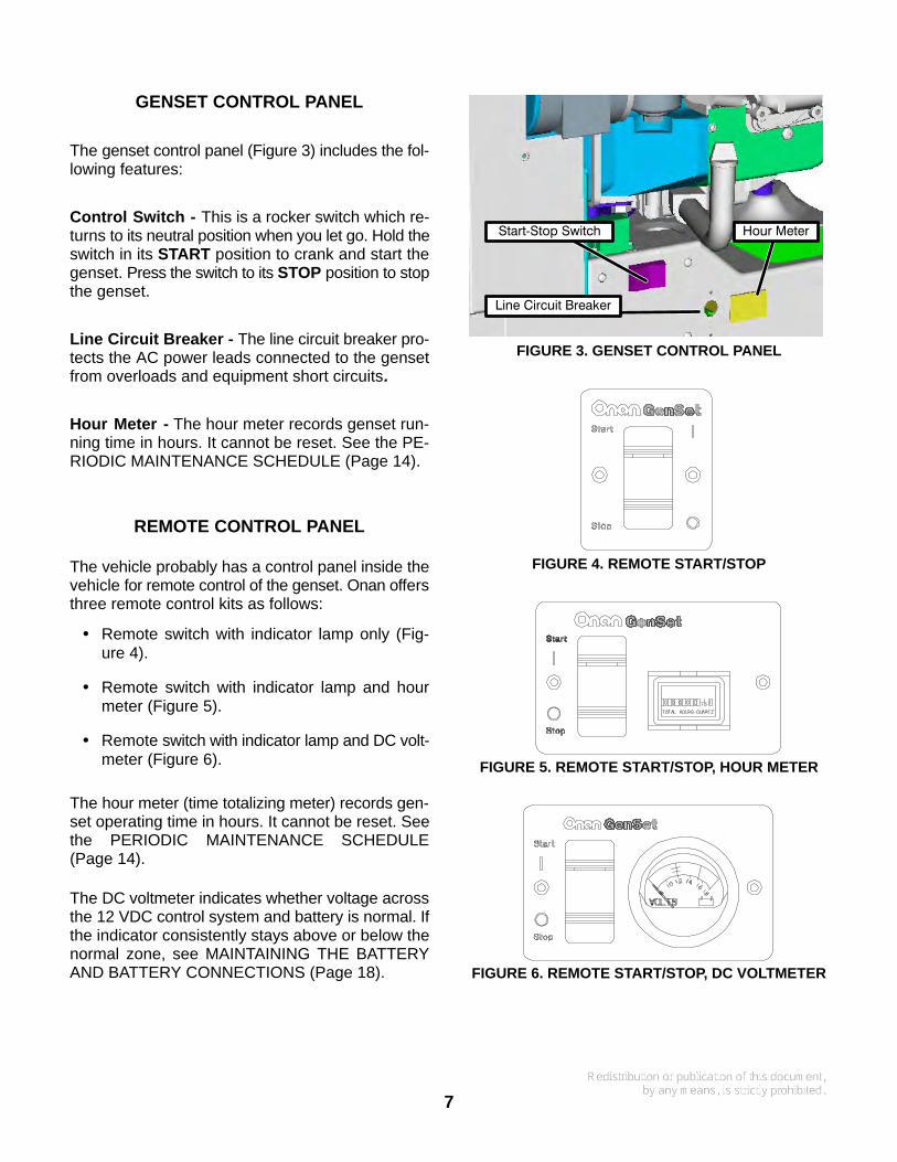
The genset control panel (Figure 3) includes the fol-lowing features:
Control Switch - This is a rocker switch which re-turns to its neutral position when you let go. Hold theswitch in its START position to crank and start thegenset. Press the switch to its STOP position to stopthe genset.
Line Circuit Breaker - The line circuit breaker pro-tects the AC power leads connected to the gensetfrom overloads and equipment short circuits.
Hour Meter - The hour meter records genset run-ning time in hours. It cannot be reset. See the PE-RIODIC MAINTENANCE SCHEDULE (Page 14).
REMOTE CONTROL PANEL
The vehicle probably has a control panel inside thevehicle for remote control of the genset. Onan offersthree remote control kits as follows:
• Remote switch with indicator lamp only (Fig-ure 4).
• Remote switch with indicator lamp and hourmeter (Figure 5).
• Remote switch with indicator lamp and DC volt-meter (Figure 6).
The hour meter (time totalizing meter) records gen-set operating time in hours. It cannot be reset. Seethe PERIODIC MAINTENANCE SCHEDULE(Page 14).
The DC voltmeter indicates whether voltage acrossthe 12 VDC control system and battery is normal. Ifthe indicator consistently stays above or below thenormal zone, see MAINTAINING THE BATTERYAND BATTERY CONNECTIONS (Page 18).
Start−Stop Switch
Line Circuit Breaker
Hour Meter
FIGURE 3. GENSET CONTROL PANEL
FIGURE 4. REMOTE START/STOP
FIGURE 5. REMOTE START/STOP, HOUR METER
FIGURE 6. REMOTE START/STOP, DC VOLTMETER
8
Operation
WARNING EXHAUST GAS IS DEADLY!
Exhaust gases contain carbon monoxide, an odorless, colorless gas. Carbon monoxide is poisonousand can cause unconsciousness and death. Symptoms of carbon monoxide poisoning include:
• Dizziness • Throbbing in Temples • Nausea• Muscular Twitching • Headache • Vomiting• Weakness and Sleepiness • Inability to Think Clearly
IF YOU OR ANYONE ELSE EXPERIENCES ANY OF THESE SYMPTOMS, GET OUT INTO THE FRESHAIR IMMEDIATELY. If symptoms persist, seek medical attention. Shut down the genset and do not op-erate it until it has been inspected and repaired.
Never sleep in the vehicle with the genset running unless the vehicle is equipped with a working car-bon monoxide detector. Primary protection against inhaling carbon monoxide, however, is properinstallation of the exhaust system, daily (every eight hour) inspection for visible and audible exhaustsystem leaks.
CONDUCTING THE PRE-START CHECKS
Before the first start of the day and after every eighthours of operation, inspect the genset as instructedunder CONDUCTING GENERAL INSPECTIONS(Page 15). Keep a log of maintenance and the hoursrun and perform any maintenance that may be due.See Returning the Genset to Service (Page 13) ifthe vehicle has been in storage.
Before each start:
1. Make sure all vehicle CO detectors are work-ing.
2. Check for signs of fuel and exhaust leaks andfor damage to the exhaust system.
3. To prevent overheating and to reduce foulingwith dust and debris, make sure the genset’snormal ground clearance is not being reducedby sloping ground, curbs, logs or other objects.Repark the vehicle if necessary and/or removeany objects blocking the air inlet or air outlet.
4. Turn off the air conditioner and other large ap-pliances.
STARTING THE GENSET
Start the genset from the genset control panel or re-mote control panel inside the vehicle (Page 7).
1. Push and hold the switch at START until thegenset starts. (The remote START switch in-side the vehicle should have a lamp whichlights to indicate that the genset has started andis running.)
CAUTION Cranking for longer than 10 sec-onds at a time can overheat and damage thestarter. Do not crank for more than 10 sec-onds at a time and wait at least 30 secondsbefore trying again.
2. For top performance and engine life, especiallyin colder weather, let the engine warm up fortwo minutes before connecting appliances.
3. Check for fuel and exhaust leaks. Stop the gen-set immediately if there is a fuel or exhaust leakand have it repaired.
4. See Troubleshooting (Page 21) if the enginedoes not crank or start after several tries.
5. Always secure the genset compartment doorafter starting the genset at the genset controlpanel.
WARNING Operating the genset with thecompartment door off can lead to severeburns and engine damage due to overheat-ing. Always secure the door after startingthe genset.
9
STOPPING THE GENSET
Turn off the air conditioner and other large ap-pliances and let the genset run for two minutes tocool down. This reduces backfiring and run-on.Then press the switch to STOP to stop the genset.
RESTARTING THE GENSET
If the genset shuts down, disconnect or turn off asmany appliances as possible and try restarting thegenset. Reconnect only as many appliances as willnot overload the genset or cause the circuit breakerto trip.
LOADING THE GENSET
The genset can power AC motors, air conditioners,AC/DC converters and other appliances. How muchappliance load* can be serviced depends upon thegenset power rating. The genset will shut down or itscircuit breakers will trip if the sum of the loads ex-ceeds genset power.
To avoid overloading the genset and causing shut-downs, compare the sum of the loads of the ap-pliances that are likely to be used at the same time tothe power rating of the genset. Use Table 2 or theratings on the appliances themselves (if so marked)to obtain the individual appliance loads. It may benecessary to run fewer appliances at the sametime—the sum of the loads must not be greaterthan genset rating.
Note that the genset may shut down due to over-load—even though the sum of the loads is less thangenset rating—when a large motor or air conditioneris started last or cycles off and then on again. Thereason for this is that motor startup load is muchlarger than running load. It may be necessary torun fewer appliances when large motors and airconditioners are cycling on and off.
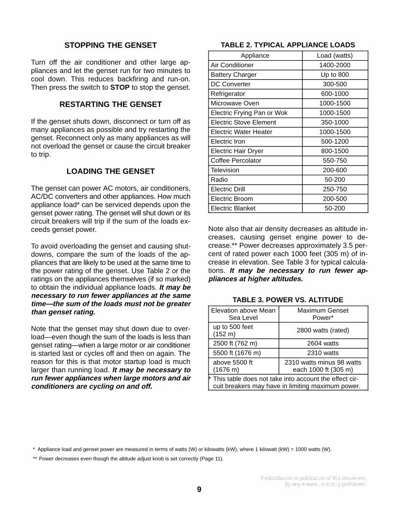
TABLE 2. TYPICAL APPLIANCE LOADSAppliance Load (watts)
Air Conditioner 1400-2000
Battery Charger Up to 800
DC Converter 300-500
Refrigerator 600-1000
Microwave Oven 1000-1500
Electric Frying Pan or Wok 1000-1500
Electric Stove Element 350-1000
Electric Water Heater 1000-1500
Electric Iron 500-1200
Electric Hair Dryer 800-1500
Coffee Percolator 550-750
Television 200-600
Radio 50-200
Electric Drill 250-750
Electric Broom 200-500
Electric Blanket 50-200
Note also that air density decreases as altitude in-creases, causing genset engine power to de-crease.** Power decreases approximately 3.5 per-cent of rated power each 1000 feet (305 m) of in-crease in elevation. See Table 3 for typical calcula-tions. It may be necessary to run fewer ap-pliances at higher altitudes.
TABLE 3. POWER VS. ALTITUDEElevation above Mean
Sea LevelMaximum Genset
Power*up to 500 feet(152 m)
2800 watts (rated)
2500 ft (762 m) 2604 watts
5500 ft (1676 m) 2310 watts
above 5500 ft(1676 m)
2310 watts minus 98 wattseach 1000 ft (305 m)
* This table does not take into account the effect cir-cuit breakers may have in limiting maximum power.
* Appliance load and genset power are measured in terms of watts (W) or kilowatts (kW), where 1 kilowatt (kW) = 1000 watts (W).
** Power decreases even though the altitude adjust knob is set correctly (Page 11).
10
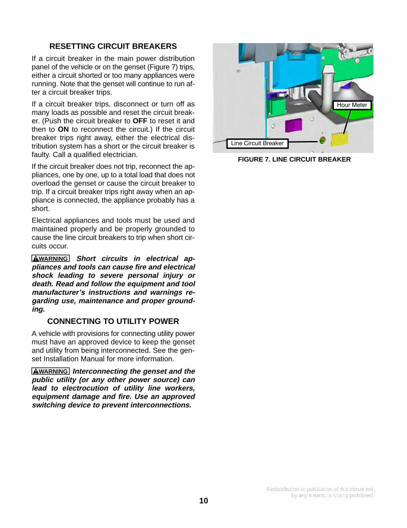
RESETTING CIRCUIT BREAKERS
If a circuit breaker in the main power distributionpanel of the vehicle or on the genset (Figure 7) trips,either a circuit shorted or too many appliances wererunning. Note that the genset will continue to run af-ter a circuit breaker trips.
If a circuit breaker trips, disconnect or turn off asmany loads as possible and reset the circuit break-er. (Push the circuit breaker to OFF to reset it andthen to ON to reconnect the circuit.) If the circuitbreaker trips right away, either the electrical dis-tribution system has a short or the circuit breaker isfaulty. Call a qualified electrician.
If the circuit breaker does not trip, reconnect the ap-pliances, one by one, up to a total load that does notoverload the genset or cause the circuit breaker totrip. If a circuit breaker trips right away when an ap-pliance is connected, the appliance probably has ashort.
Electrical appliances and tools must be used andmaintained properly and be properly grounded tocause the line circuit breakers to trip when short cir-cuits occur.
WARNING Short circuits in electrical ap-pliances and tools can cause fire and electricalshock leading to severe personal injury ordeath. Read and follow the equipment and toolmanufacturer’s instructions and warnings re-garding use, maintenance and proper ground-ing.
CONNECTING TO UTILITY POWER
A vehicle with provisions for connecting utility powermust have an approved device to keep the gensetand utility from being interconnected. See the gen-set Installation Manual for more information.
WARNING Interconnecting the genset and thepublic utility (or any other power source) canlead to electrocution of utility line workers,equipment damage and fire. Use an approvedswitching device to prevent interconnections.
Line Circuit Breaker
Hour Meter
FIGURE 7. LINE CIRCUIT BREAKER
11
OPERATING IN COLD WEATHER
Pay particular attention to the following items whenoperating the genset in cold weather:
1. Make sure engine oil viscosity is appropriate forthe ambient temperatures. Change oil if thereis a sudden drop in temperature. See ENGINEOIL RECOMMENDATIONS (Page 6).
2. Reset the carburetor for altitude (Figure 8).3. Perform spark plug maintenance (Page 19).4. Perform battery maintenance (Page 18).
OPERATING IN HOT WEATHER
Pay particular attention to the following items whenoperating the genset in hot weather:
1. Make sure nothing blocks the airflow to andfrom the set.
2. Make sure engine oil viscosity is appropriate forthe ambient temperatures. See ENGINE OILRECOMMENDATIONS (Page 6).
3. Keep the genset clean.4. Perform maintenance due. See PERIODIC
MAINTENANCE SCHEDULE (Page 14).5. Reset the carburetor for altitude (Figure 8).
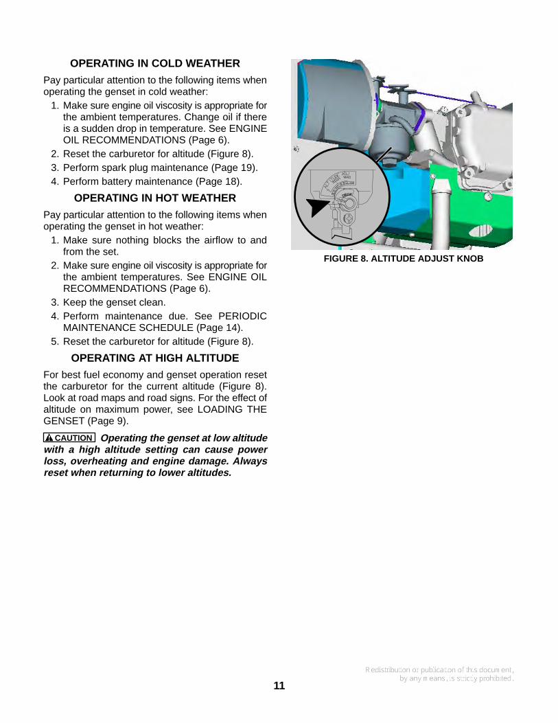
OPERATING AT HIGH ALTITUDE
For best fuel economy and genset operation resetthe carburetor for the current altitude (Figure 8).Look at road maps and road signs. For the effect ofaltitude on maximum power, see LOADING THEGENSET (Page 9).
CAUTION Operating the genset at low altitudewith a high altitude setting can cause powerloss, overheating and engine damage. Alwaysreset when returning to lower altitudes.
FIGURE 8. ALTITUDE ADJUST KNOB
12
OPERATING IN DUSTY ENVIRONMENTS
Pay particular attention to the following items whenoperating the genset in dusty environments:
1. Do not let dirt and debris accumulate inside thegenset compartment. Keep the genset clean.
2. Perform air cleaner maintenance more often(Page 14).
3. Change engine oil every 50 hours.
4. Keep containers of engine oil that have beenopened tightly closed to keep out dust.
BREAKING IN A NEW ENGINE
Proper engine break-in on a new genset or on onewith a rebuilt engine is essential for top engine per-formance and acceptable oil consumption. Run thegenset at approximately 1/2 rated power for the first2 hours and then at 3/4 rated power for 2 morehours. See LOADING THE GENSET (Page 9).
Proper engine oil and oil level are especially criticalduring break-in because of the higher engine tem-peratures that can be expected. Change the oil if notappropriate for the ambient temperatures duringbreak-in. See ENGINE OIL RECOMMENDATIONS(Page 6). Check oil level twice a day or every4 hours during the first 20 hours of operation andchange the oil after the first 20 hours of operation.
EXERCISING THE GENSET
Exercise the genset at least 2 hours each month ifuse is infrequent. Run the genset at approximately1/2 rated power. See LOADING THE GENSET(Page 9). A single two hour exercise period is bet-ter than several shorter periods.
Exercising a genset drives off moisture, re-lubri-cates the engine, replaces stale fuel in fuel lines andcarburetor and removes oxides from electrical con-tacts and generator slip rings. The result is betterstarting, more reliable operation and longer enginelife.
STORING THE GENSET
Proper storage is essential for preserving top gen-set performance and reliability when the gensetcannot be exercised regularly and will be idle formore than 120 days.
Storing the Genset
1. Fill the fuel tank with fresh fuel and add a fuelpreservative (OnaFreshTM), following the in-structions on the container label. Unless a pre-servative (stabilizer) is added, the gasoline inthe fuel system will deteriorate causing fuelsystem corrosion, gum formation and varnish-like deposits which can lead to hard startingand rough operation.
Then run the genset for about 10 minutes atapproximately 1/2 rated power to fill the fuellines with the fresh fuel and preservative.
WARNING Gasoline preservatives (stabil-izers) are toxic. Follow the instructions onthe container label. Avoid skin contact.Wash your hands with soap and water afterdispensing the fluid.
2. Change the engine oil and attach a tag indicat-ing its oil viscosity (Page 6).
3. Remove the air filter and restart the genset.While the genset is running, spray an enginefogger (OnaGardTM) into the carburetor, follow-ing the instructions on the container label, andthen stop the genset. The fogger leaves a pro-tective coat of oil on the internal surfaces of theengine.
4. Disconnect the battery cables, negative (- )cable first, from the starting battery and storethe battery according to the battery manufac-turer’s recommendations (Page 18).
5. Plug the exhaust tail pipe to keep out dirt, mois-ture, rodents and such.
6. Close the fuel supply valve (if so equipped).
7. Turn OFF the AC circuit breaker (Page 10).
OnaFresh and OnaGard are trademarks of Onan Corporation.
13
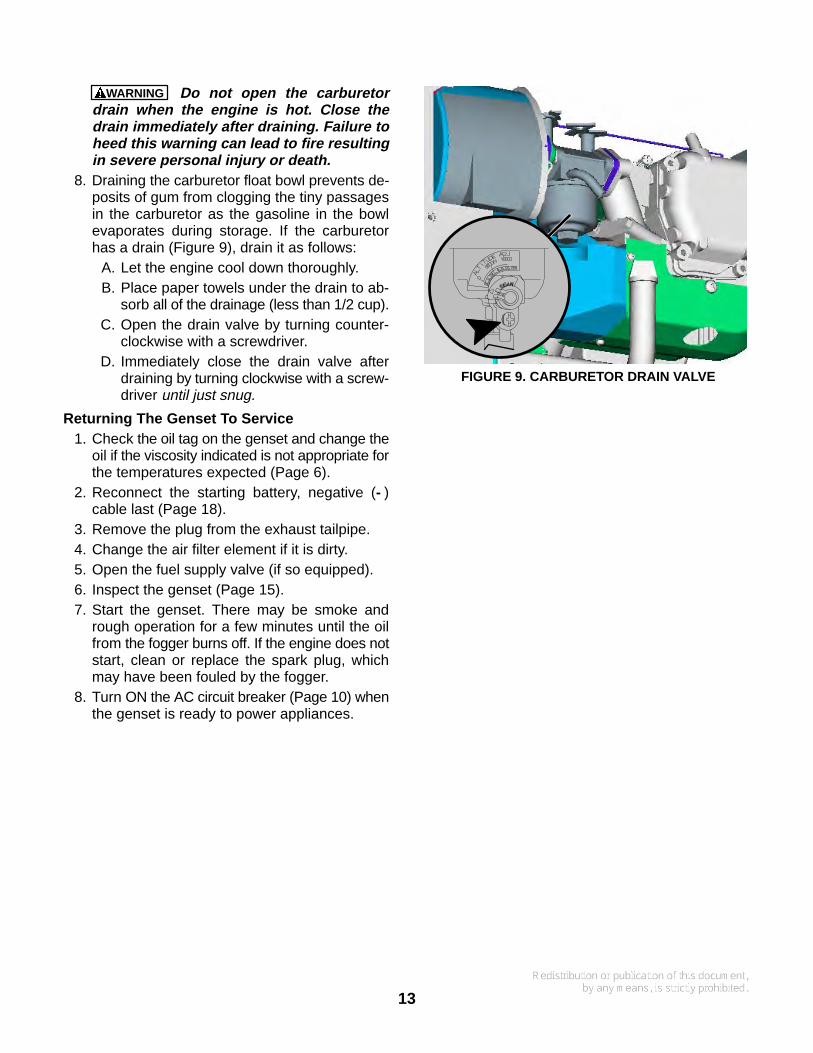
WARNING Do not open the carburetordrain when the engine is hot. Close thedrain immediately after draining. Failure toheed this warning can lead to fire resultingin severe personal injury or death.
8. Draining the carburetor float bowl prevents de-posits of gum from clogging the tiny passagesin the carburetor as the gasoline in the bowlevaporates during storage. If the carburetorhas a drain (Figure 9), drain it as follows:
A. Let the engine cool down thoroughly.B. Place paper towels under the drain to ab-
sorb all of the drainage (less than 1/2 cup).C. Open the drain valve by turning counter-
clockwise with a screwdriver.D. Immediately close the drain valve after
draining by turning clockwise with a screw-driver until just snug.
Returning The Genset To Service1. Check the oil tag on the genset and change the
oil if the viscosity indicated is not appropriate forthe temperatures expected (Page 6).
2. Reconnect the starting battery, negative (- )cable last (Page 18).
3. Remove the plug from the exhaust tailpipe.4. Change the air filter element if it is dirty.5. Open the fuel supply valve (if so equipped).6. Inspect the genset (Page 15).7. Start the genset. There may be smoke and
rough operation for a few minutes until the oilfrom the fogger burns off. If the engine does notstart, clean or replace the spark plug, whichmay have been fouled by the fogger.
8. Turn ON the AC circuit breaker (Page 10) whenthe genset is ready to power appliances.
FIGURE 9. CARBURETOR DRAIN VALVE
14
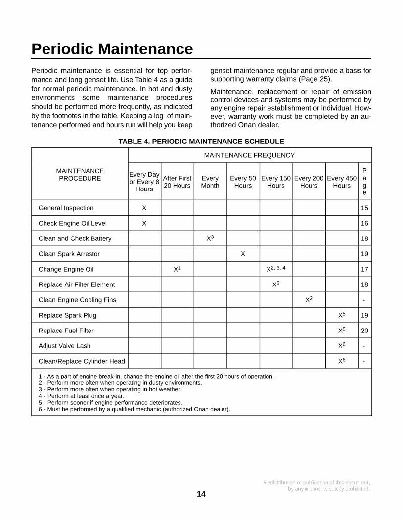
Periodic MaintenancePeriodic maintenance is essential for top perfor-mance and long genset life. Use Table 4 as a guidefor normal periodic maintenance. In hot and dustyenvironments some maintenance proceduresshould be performed more frequently, as indicatedby the footnotes in the table. Keeping a log of main-tenance performed and hours run will help you keep
genset maintenance regular and provide a basis forsupporting warranty claims (Page 25).
Maintenance, replacement or repair of emissioncontrol devices and systems may be performed byany engine repair establishment or individual. How-ever, warranty work must be completed by an au-thorized Onan dealer.
TABLE 4. PERIODIC MAINTENANCE SCHEDULE
MAINTENANCE FREQUENCY
MAINTENANCEPROCEDURE
Every Dayor Every 8
Hours
After First20 Hours
EveryMonth
Every 50Hours
Every 150Hours
Every 200Hours
Every 450Hours
Page
General Inspection X 15
Check Engine Oil Level X 16
Clean and Check Battery X3 18
Clean Spark Arrestor X 19
Change Engine Oil X1 X2, 3, 4 17
Replace Air Filter Element X2 18
Clean Engine Cooling Fins X2 -
Replace Spark Plug X5 19
Replace Fuel Filter X5 20
Adjust Valve Lash X6 -
Clean/Replace Cylinder Head X6 -
1 - As a part of engine break-in, change the engine oil after the first 20 hours of operation.2 - Perform more often when operating in dusty environments.3 - Perform more often when operating in hot weather.4 - Perform at least once a year.5 - Perform sooner if engine performance deteriorates.6 - Must be performed by a qualified mechanic (authorized Onan dealer).
15
CONDUCTING GENERAL INSPECTIONS
Inspect the genset before the first start of the dayand after every eight hours of operation.
Oil Level
Check engine oil level (Page 16).
Exhaust System
Look and listen for exhaust system leaks while thegenset is running. Shut down the genset if a leak isfound and have it repaired before operating the gen-set again.
Look for openings or holes between the gensetcompartment and vehicle cab or living space if thegenset engine sounds louder than usual. Have allsuch openings or holes closed off or sealed to pre-vent exhaust gases from entering the vehicle.
Replace dented, bent or severely rusted sections ofthe tailpipe and make sure the tailpipe extends atleast 1 inch (25.4 mm) beyond the perimeter of thevehicle.
Park the vehicle so that the genset exhaust gasescan disperse away from the vehicle. Barriers suchas walls, snow banks, high grass, brush and othervehicles can cause exhaust gases to accumulate inand around the vehicle.
Do not operate power ventilators or exhaust fanswhile the vehicle is standing with the genset run-ning. The ventilator or fan can draw exhaust gasesinto the vehicle.
WARNING EXHAUST GAS IS DEADLY! Do notoperate the genset if there is an exhaust leak orany danger of exhaust gases entering or beingdrawn into the vehicle.
WARNING Do not park the vehicle in high grassor brush. Contact with the exhaust system cancause a fire.
Fuel System
Check for leaks at the hose, tube and pipe fittings inthe fuel supply system while the genset is running
and while it is stopped. Check flexible fuel hose sec-tions for cuts, cracks, and abrasions. Make sure thefuel line is not rubbing against other parts. Replaceworn or damaged fuel line parts before leaks occur.
WARNING Gasoline is highly flammable andexplosive and can cause severe personal injuryor death. Shut down the genset and repair leaksimmediately.
Battery Connections
Check the battery terminals for clean, tight connec-tions. Loose or corroded connections have highelectrical resistance which makes starting harder.See MAINTAINING THE BATTERY AND BATTERYCONNECTIONS (Page 18).
WARNING Arcing at battery terminals or lightswitch or other equipment or flames and sparkscan ignite battery gas causing severe personalinjury—Ventilate battery area before working onor near battery—Wear safety glasses—Do notsmoke—Switch trouble light ON / OFF awayfrom battery—Do not disconnect battery cableswhile genset is running or vehicle battery charg-ing system is on—Always disconnect nega-tive (-) cable first and reconnect it last.
Mechanical
Look for mechanical damage. Start the genset andlook, listen and feel for any unusual noises andvibrations.
Check the genset mounting bolts to make sure theyare secure.
Check to see that the genset air inlet and outletopenings are not clogged with debris or blocked.
Clean accumulated dust and dirt from the genset.Do not clean the genset while it is running or still hot.Protect the generator, air cleaner, control panel, andelectrical connections from water, soap and clean-ing solvents.
WARNING Always wear safety glasses whenusing compressed air, a pressure washer or asteam cleaner to avoid severe eye injury.
16
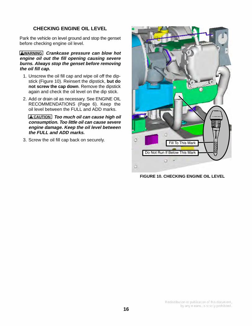
CHECKING ENGINE OIL LEVEL
Park the vehicle on level ground and stop the gensetbefore checking engine oil level.
WARNING Crankcase pressure can blow hotengine oil out the fill opening causing severeburns. Always stop the genset before removingthe oil fill cap.
1. Unscrew the oil fill cap and wipe oil off the dip-stick (Figure 10). Reinsert the dipstick, but donot screw the cap down . Remove the dipstickagain and check the oil level on the dip stick.
2. Add or drain oil as necessary. See ENGINE OILRECOMMENDATIONS (Page 6). Keep theoil level between the FULL and ADD marks.
CAUTION Too much oil can cause high oilconsumption. Too little oil can cause severeengine damage. Keep the oil level betweenthe FULL and ADD marks.
3. Screw the oil fill cap back on securely.Fill To This Mark
Do Not Run If Below This Mark
FIGURE 10. CHECKING ENGINE OIL LEVEL
17
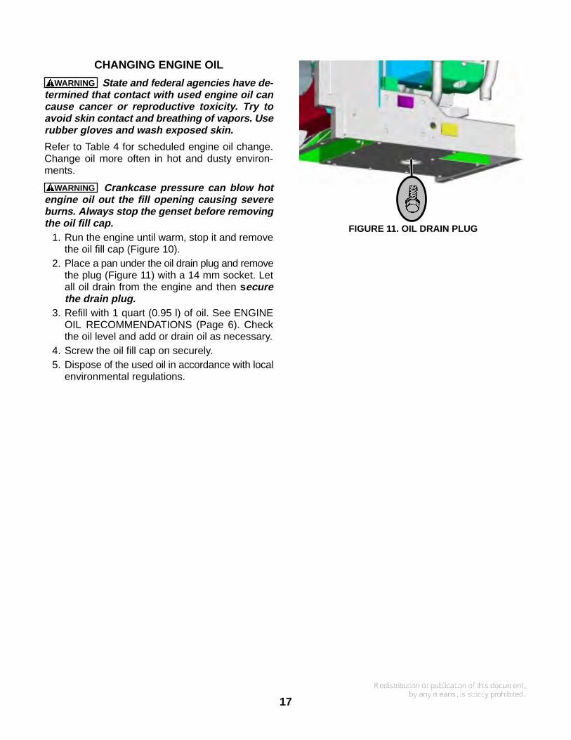
CHANGING ENGINE OIL
WARNING State and federal agencies have de-termined that contact with used engine oil cancause cancer or reproductive toxicity. Try toavoid skin contact and breathing of vapors. Userubber gloves and wash exposed skin.
Refer to Table 4 for scheduled engine oil change.Change oil more often in hot and dusty environ-ments.
WARNING Crankcase pressure can blow hotengine oil out the fill opening causing severeburns. Always stop the genset before removingthe oil fill cap.
1. Run the engine until warm, stop it and removethe oil fill cap (Figure 10).
2. Place a pan under the oil drain plug and removethe plug (Figure 11) with a 14 mm socket. Letall oil drain from the engine and then securethe drain plug.
3. Refill with 1 quart (0.95 l) of oil. See ENGINEOIL RECOMMENDATIONS (Page 6). Checkthe oil level and add or drain oil as necessary.
4. Screw the oil fill cap on securely.5. Dispose of the used oil in accordance with local
environmental regulations.
FIGURE 11. OIL DRAIN PLUG
18
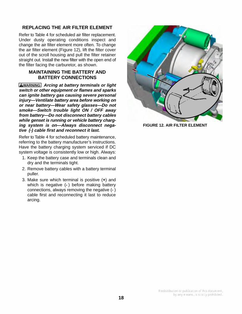
REPLACING THE AIR FILTER ELEMENT
Refer to Table 4 for scheduled air filter replacement.Under dusty operating conditions inspect andchange the air filter element more often. To changethe air filter element (Figure 12), lift the filter coverout of the scroll housing and pull the filter retainerstraight out. Install the new filter with the open end ofthe filter facing the carburetor, as shown.
MAINTAINING THE BATTERY ANDBATTERY CONNECTIONS
WARNING Arcing at battery terminals or lightswitch or other equipment or flames and sparkscan ignite battery gas causing severe personalinjury—Ventilate battery area before working onor near battery—Wear safety glasses—Do notsmoke—Switch trouble light ON / OFF awayfrom battery—Do not disconnect battery cableswhile genset is running or vehicle battery charg-ing system is on—Always disconnect nega-tive (-) cable first and reconnect it last.
Refer to Table 4 for scheduled battery maintenance,referring to the battery manufacturer’s instructions.Have the battery charging system serviced if DCsystem voltage is consistently low or high. Always:
1. Keep the battery case and terminals clean anddry and the terminals tight.
2. Remove battery cables with a battery terminalpuller.
3. Make sure which terminal is positive (+) andwhich is negative (- ) before making batteryconnections, always removing the negative (- )cable first and reconnecting it last to reducearcing.
FIGURE 12. AIR FILTER ELEMENT
19
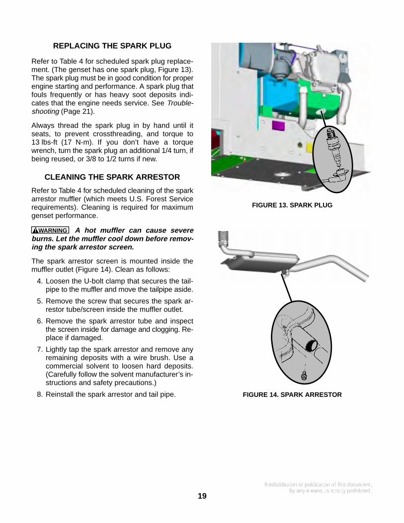
REPLACING THE SPARK PLUG
Refer to Table 4 for scheduled spark plug replace-ment. (The genset has one spark plug, Figure 13).The spark plug must be in good condition for properengine starting and performance. A spark plug thatfouls frequently or has heavy soot deposits indi-cates that the engine needs service. See Trouble-shooting (Page 21).
Always thread the spark plug in by hand until itseats, to prevent crossthreading, and torque to13 lbs-ft (17 N-m). If you don’t have a torquewrench, turn the spark plug an additional 1/4 turn, ifbeing reused, or 3/8 to 1/2 turns if new.
CLEANING THE SPARK ARRESTOR
Refer to Table 4 for scheduled cleaning of the sparkarrestor muffler (which meets U.S. Forest Servicerequirements). Cleaning is required for maximumgenset performance.
WARNING A hot muffler can cause severeburns. Let the muffler cool down before remov-ing the spark arrestor screen.
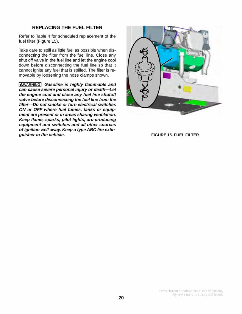
The spark arrestor screen is mounted inside themuffler outlet (Figure 14). Clean as follows:
4. Loosen the U-bolt clamp that secures the tail-pipe to the muffler and move the tailpipe aside.
5. Remove the screw that secures the spark ar-restor tube/screen inside the muffler outlet.
6. Remove the spark arrestor tube and inspectthe screen inside for damage and clogging. Re-place if damaged.
7. Lightly tap the spark arrestor and remove anyremaining deposits with a wire brush. Use acommercial solvent to loosen hard deposits.(Carefully follow the solvent manufacturer’s in-structions and safety precautions.)
8. Reinstall the spark arrestor and tail pipe.
FIGURE 13. SPARK PLUG
FIGURE 14. SPARK ARRESTOR
20
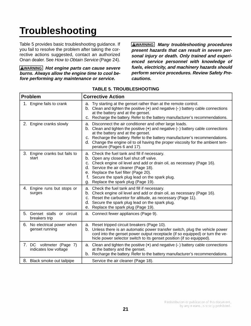
REPLACING THE FUEL FILTER
Refer to Table 4 for scheduled replacement of thefuel filter (Figure 15).
Take care to spill as little fuel as possible when dis-connecting the filter from the fuel line. Close anyshut off valve in the fuel line and let the engine cooldown before disconnecting the fuel line so that itcannot ignite any fuel that is spilled. The filter is re-movable by loosening the hose clamps shown.
WARNING Gasoline is highly flammable andcan cause severe personal injury or death—Letthe engine cool and close any fuel line shutoffvalve before disconnecting the fuel line from thefilter—Do not smoke or turn electrical switchesON or OFF where fuel fumes, tanks or equip-ment are present or in areas sharing ventilation.Keep flame, sparks, pilot lights, arc-producingequipment and switches and all other sourcesof ignition well away. Keep a type ABC fire extin-guisher in the vehicle. FIGURE 15. FUEL FILTER
21
TroubleshootingTable 5 provides basic troubleshooting guidance. Ifyou fail to resolve the problem after taking the cor-rective actions suggested, contact an authorizedOnan dealer. See How to Obtain Service (Page 24).
WARNING Hot engine parts can cause severeburns. Always allow the engine time to cool be-fore performing any maintenance or service.
WARNING Many troubleshooting procedurespresent hazards that can result in severe per-sonal injury or death. Only trained and experi-enced service personnel with knowledge offuels, electricity, and machinery hazards shouldperform service procedures. Review Safety Pre-cautions.
TABLE 5. TROUBLESHOOTING
Problem Corrective Action1. Engine fails to crank a. Try starting at the genset rather than at the remote control.
b. Clean and tighten the positive (+) and negative (- ) battery cable connectionsat the battery and at the genset.
c. Recharge the battery. Refer to the battery manufacturer’s recommendations.
2. Engine cranks slowly a. Disconnect the air conditioner and other large loads.b. Clean and tighten the positive (+) and negative (- ) battery cable connections
at the battery and at the genset.c. Recharge the battery. Refer to the battery manufacturer’s recommendations.d. Change the engine oil to oil having the proper viscosity for the ambient tem-
perature (Pages 6 and 17).
3. Engine cranks but fails tostart
a. Check the fuel tank and fill if necessary.b. Open any closed fuel shut off valve.c. Check engine oil level and add or drain oil, as necessary (Page 16).d. Service the air cleaner (Page 18).e. Replace the fuel filter (Page 20).f. Secure the spark plug lead on the spark plug.
g. Replace the spark plug (Page 19).
4. Engine runs but stops orsurges
a. Check the fuel tank and fill if necessary.b. Check engine oil level and add or drain oil, as necessary (Page 16).c. Reset the carburetor for altitude, as necessary (Page 11).d. Secure the spark plug lead on the spark plug.e. Replace the spark plug (Page 19).
5. Genset stalls or circuitbreakers trip
a. Connect fewer appliances (Page 9).
6. No electrical power whengenset running
a. Reset tripped circuit breakers (Page 10).b. Unless there is an automatic power transfer switch, plug the vehicle power
cord into the genset power output receptacle (if so equipped) or turn the ve-hicle power selector switch to its genset position (if so equipped).
7. DC voltmeter (Page 7)indicates low voltage
a. Clean and tighten the positive (+) and negative (- ) battery cable connectionsat the battery and the genset.
b. Recharge the battery. Refer to the battery manufacturer’s recommendations.
8. Black smoke out tailpipe Service the air cleaner (Page 18).
22
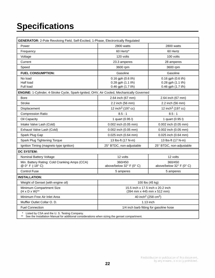
Specifications
GENERATOR: 2-Pole Revolving Field, Self-Excited, 1-Phase, Electronically Regulated
Power 2800 watts 2800 watts
Frequency 60 Hertz* 60 Hertz
Voltage 120 volts 100 volts
Current 23.3 amperes 28 amperes
Speed 3600 rpm 3600 rpm
FUEL CONSUMPTION: Gasoline Gasoline
No loadHalf loadFull load
0.16 gph (0.6 l/h)0.28 gph (1.1 l/h)0.46 gph (1.7 l/h)
0.16 gph (0.6 l/h)0.28 gph (1.1 l/h)0.46 gph (1.7 l/h)
ENGINE: 1-Cylinder, 4-Stroke Cycle, Spark-Ignited, OHV, Air Cooled, Mechanically Governed
Bore 2.64 inch (67 mm) 2.64 inch (67 mm)
Stroke 2.2 inch (56 mm) 2.2 inch (56 mm)
Displacement 12 inch3 (197 cc) 12 inch3 (197 cc)
Compression Ratio 8.5 : 1 8.5 : 1
Oil Capacity 1 quart (0.95 l) 1 quart (0.95 l)
Intake Valve Lash (Cold) 0.002 inch (0.05 mm) 0.002 inch (0.05 mm)
Exhaust Valve Lash (Cold) 0.002 inch (0.05 mm) 0.002 inch (0.05 mm)
Spark Plug Gap 0.025 inch (0.64 mm) 0.025 inch (0.64 mm)
Spark Plug Tightening Torque 13 lbs-ft (17 N-m) 13 lbs-ft (17 N-m)
Ignition Timing (magneto type ignition) 25° BTDC, non-adjustable 25° BTDC, non-adjustable
DC SYSTEM:
Nominal Battery Voltage 12 volts 12 volts
Min. Battery Rating: Cold Cranking Amps (CCA)@ 0° F (-18° C)
360/450above/below 32° F (0° C)
360/450above/below 32° F (0° C)
Control Fuse 5 amperes 5 amperes
INSTALLATION:
Weight of Genset (with engine oil) 100 lbs (45 kg)
Minimum Compartment Size(H x D x W)**
15.5 inch x 17.5 inch x 20.2 inch(394 mm x 445 mm x 512 mm)
Minimum Free Air Inlet Area 40 inch2 (258 cm2)
Muffler Outlet Collar O. D. 1.13 inch
Fuel Connection 1/4 inch barb fitting for gasoline hose
* Listed by CSA and the U. S. Testing Company.** See the Installation Manual for additional considerations when sizing the genset compartment.
23
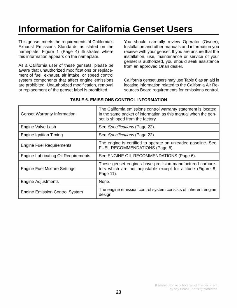
Information for California Genset UsersThis genset meets the requirements of California’sExhaust Emissions Standards as stated on thenameplate. Figure 1 (Page 4) illustrates wherethis information appears on the nameplate.
As a California user of these gensets, please beaware that unauthorized modifications or replace-ment of fuel, exhaust, air intake, or speed controlsystem components that affect engine emissionsare prohibited. Unauthorized modification, removalor replacement of the genset label is prohibited.
You should carefully review Operator (Owner),Installation and other manuals and information youreceive with your genset. If you are unsure that theinstallation, use, maintenance or service of yourgenset is authorized, you should seek assistancefrom an approved Onan dealer.
California genset users may use Table 6 as an aid inlocating information related to the California Air Re-sources Board requirements for emissions control.
TABLE 6. EMISSIONS CONTROL INFORMATION
Genset Warranty InformationThe California emissions control warranty statement is locatedin the same packet of information as this manual when the gen-set is shipped from the factory.
Engine Valve Lash See Specifications (Page 22).
Engine Ignition Timing See Specifications (Page 22).
Engine Fuel Requirements The engine is certified to operate on unleaded gasoline. SeeFUEL RECOMMENDATIONS (Page 6).
Engine Lubricating Oil Requirements See ENGINE OIL RECOMMENDATIONS (Page 6).
Engine Fuel Mixture SettingsThese genset engines have precision-manufactured carbure-tors which are not adjustable except for altitude (Figure 8,Page 11).
Engine Adjustments None.
Engine Emission Control System The engine emission control system consists of inherent enginedesign.
24
How to Obtain ServiceWhen you need service, parts, or product literature(such as the Service Manual) for your genset, con-tact the nearest authorized distributor. Onan hasfactory-trained representatives to handle yourneeds for genset parts and service.
Call 1-800-888-ONAN to contact the nearest Cum-mins/Onan or Onan-only distributor in the UnitedStates or Canada. (This automated service utilizestouch-tone phones only). Select OPTION 1(press 1) to be automatically connected to the dis-tributor nearest to you.
If you are unable to contact a distributor using theautomated service, consult the Yellow Pages. Typi-cally, our distributors are listed under:
GENERATORS - ELECTRIC,ENGINES - GASOLINE OR DIESEL, orRECREATIONAL VEHICLES - EQUIPMENT,PARTS AND SERVICE.
If you are outside North America, call Onan Corpo-ration at 1-763-574-5000 from 7:30 AM to
4:00 PM, Central Standard Time, Monday throughFriday, or fax 1-763-528-7229.
Before calling for service, have the following infor-mation available:
1. The complete genset model number and serialnumber. See Model Identification (Page 4).
2. The date of purchase
3. The nature of the problem. See Troubleshoot-ing (Page 21).
If you have difficulty in arranging service or resolv-ing a problem, please contact the Service Managerat the nearest Cummins/Onan distributor for assis-tance.
WARNING Improper service or replacement ofparts can result in severe personal injury, death,and/or equipment damage. Service personnelmust be trained and experienced in performingelectrical and/or mechanical service.
25
Maintenance RecordRecord all periodic and unscheduled maintenance and service. See Periodic Maintenance (Page 14).
DATEHOUR
METERREADING
MAINTENANCE OR SERVICE PERFORMED
Record the name, address, and phone number of your authorized Onan service center.

26

Cummins Power Generation1400 73rd Avenue N.E.Minneapolis, MN 55432763-574-5000Fax: 763-528-7229
Cummins and Onan are registered trademarks of Cummins Inc.