Embed Size (px)
Citation preview

Principles of Management
Naresh Kumar Goel
HOD Electrical,
Govt. Polytechnic,
Ambala City

Learning Objectives
Define Managers And Management.
Explain What Managers Do.
Describe The Competencies Used In Managerial Work And Assess Your Current Competency Levels.

Introductory Concepts: What Are
Managerial Competencies?
Competency – a combination of knowledge,
skills, behaviors, and attitudes that contribute to
personal effectiveness
Managerial Competencies – sets of knowledge,
skill, behaviors, and attitudes that a person
needs to be effective in a wide range of positions
and various types of organizations

Why are Managerial Competencies
Important?
You need to use your strengths to do your best
You need to know your weaknesses
You need developmental experiences at work to become
successful leaders and address your weakness
You probably like to be challenged with new learning
opportunities
Organizations do not want to waste human resources
Globalization deregulation, restructuring, and new
competitors add to the complexity of running a business

A Model of Managerial Competencies
Teamwork
Competency
Global
Awareness
Competency
Strategic
Action
Competency
Planning and
Administration
Competency
Self-Management
Competency
Communication
Competency

A Model of Managerial Competencies
Teamwork
Competency
Global
Awareness
Competency
Strategic
Action
Competency
Planning and
Administration
Competency
Self-Management
Competency
Communication
Competency
Managerial
Effectiveness

What Is An Organization?
A formal and coordinated group of people who
function to achieve particular goals
These goals cannot be achieved by individuals
acting alone

Characteristics of an
Organization
An organization has a structure.
An organization consists of a group of people striving to reach goals that individuals acting alone could not achieve.

Management
Organization
Two or more people who work together in a structured
way to achieve a specific goal or set of goals.
Goals
Purpose that an organization strives to achieve;
organizations often have more than one goals, goals are
fundamental elements of organization.
The Role of Management
To guide the organizations towards goal
accomplishment

- People responsible for
directing the efforts aimed
at helping organizations
achieve their goals.
- A person who plans,
organizes, directs and
controls the allocation of
human, material, financial,
and information resources
in pursuit of the
organization’s goals.

Management
Management refers to the tasks and activities
involved in directing an organization or one of
its units: planning, organizing, leading, and
controlling.
The process of reaching organizational goals by
working with and through people and other
organizational resources.

Functional Managers: A manager responsible for
just one organizational activity such as accounting,
human resources, sales, finance, marketing, or
production
Focus on technical areas of expertise
Use communication, planning and
administration, teamwork and self-
management competencies to get work
done
Function: A classification referring to a group of
similar activities in an organization like marketing or operations.

Basic Managerial Functions
Organizing
Planning
Controlling
Leading

Management and Organizational Resources

Planning involves tasks that must be
performed to attain organizational goals,
outlining how the tasks must be performed, and
indicating when they should be performed.

Planning
Determining organizational goals and
means to reach them
Managers plan for three reasons
1. Establish an overall direction for the
organization’s future
2. Identify and commit resources to achieving goals
3. Decide which tasks must be done to reach those
goals

Organizing means assigning the planned tasks to
various individuals or groups within the
organization and cresting a mechanism to put plans
into action.

Organizing
Process of deciding where decisions will be made, who
will perform what jobs and tasks, and who will report
to whom in the company
Includes creating departments and job descriptions

Leading (Influencing) means guiding the activities
of the organization members in appropriate
directions. Objective is to improve productivity.

Leading
Getting others to perform the necessary tasks by
motivating them to achieve the organization’s goals
Crucial element in all functions

1. Gather information that measures recent performance
2. Compare present performance to pre-established standards
3. Determine modifications to meet pre-established standards

Controlling
Process by which a person, group, or
organization consciously monitors performance
and takes corrective
action

Top Managers
Responsible for providing the overall direction of an
organization
Develop goals and strategies for entire organization
Spend most of their time planning and leading
Communicate with key stakeholders—stockholders,
unions, governmental agencies, etc., company
policies
Use of multicultural and strategic action
competencies to lead firm is crucial
Levels of Management
First-line Managers: have direct responsibility for
producing goods or services Foreman, supervisors,
clerical supervisors
Middle Managers:
Coordinate employee activities
Determine which goods or services to provide
Decide how to market goods or services to customers
Assistant Manager, Manager (Section Head)
Top Managers: provide the overall direction of an
organization Chief Executive Officer, President, Vice
President

First-line Managers
Directly responsible for production of goods or services
Employees who report to first-line managers do the
organization’s work
Spend little time with top managers in large organizations
Technical expertise is important
Rely on planning and administration, self-management,
teamwork, and communication competencies to get work
done

Middle Managers
Responsible for setting objectives that are consistent with
top management’s goals and translating them into specific goals and plans for first-line managers to implement
Responsible for coordinating activities of first-line
managers
Establish target dates for products/services to be delivered
Need to coordinate with others for resources
Ability to develop others is important
Rely on communication, teamwork, and planning and
administration competencies to achieve goals

Introductory Concepts: What Are
Managerial Competencies?
Competency – a combination of knowledge,
skills, behaviors, and attitudes that contribute to
personal effectiveness
Managerial Competencies – sets of knowledge,
skill, behaviors, and attitudes that a person
needs to be effective in a wide range of positions
and various types of organizations

Six Core Managerial Competencies:
What It Takes to Be a Great Manager
Communication Competency
Planning and Administration Competency
Teamwork Competency
Strategic Action Competency
Multicultural Competency
Self-Management Competency

Communication Competency
Ability to effectively transfer and exchange information
that leads to understanding between yourself and others
Informal Communication
Used to build social networks and good
interpersonal relations
Formal Communication
Used to announce major events/decisions/
activities and keep individuals up to date
Negotiation
Used to settle disputes, obtain resources,
and exercise influence

Deciding what tasks need to be done, determining
how they can be done, allocating resources to enable
them to be done, and then monitoring progress to
ensure that they are done
Information gathering, analysis, and problem solving
from employees and customers
Planning and organizing projects with agreed
upon completion dates
Time management
Budgeting and financial management

Accomplishing tasks through small groups of
people who are collectively responsible and
whose job requires coordination
Designing teams properly involves having
people participate in setting goals
Creating a supportive team environment gets
people committed to the team’s goals
Managing team dynamics involves settling
conflicts, sharing team success, and assign tasks
that use team members’ strengths

Strategic Action Competency
Understanding the overall mission and values of
the organization and ensuring that employees’ actions match with them
Understanding how departments or divisions of
the organization are interrelated
Taking key strategic actions to position the firm
for success, especially in relation to concern of
stakeholders
Leapfrogging competitors

Understanding, appreciating and responding to
diverse political, cultural, and economic issues
across and within nations
Cultural knowledge and understanding of the
events in at least a few other cultures
Cultural openness and sensitivity to how others
think, act, and feel
Respectful of social etiquette variations
Accepting of language differences
Multicultural Competency

Self-Management Competency
Developing yourself and taking responsibility
Integrity and ethical conduct
Personal drive and resilience
Balancing work and life issues
Self-awareness and personal development
activities

CIRCUIT BREAKER
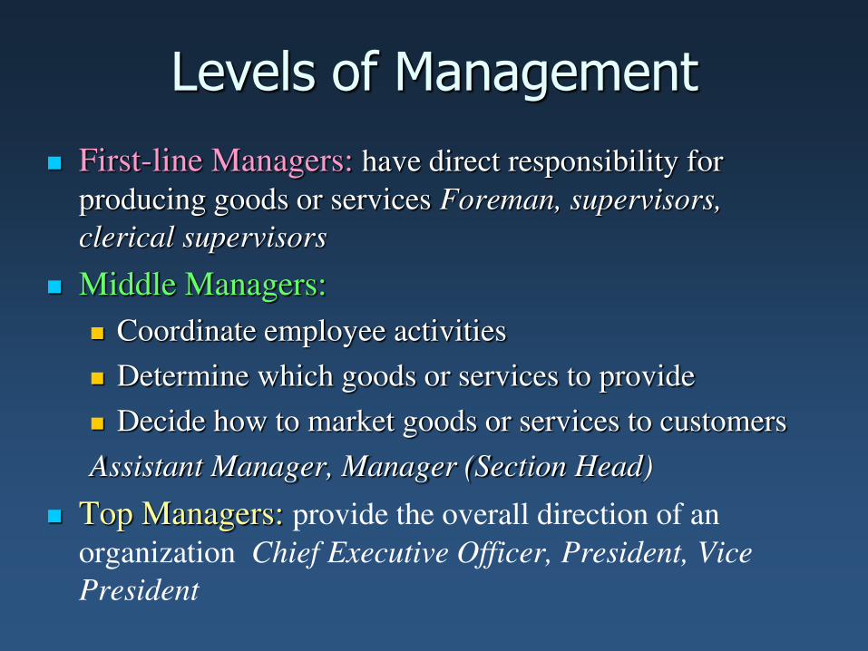
WHAT IS A CIRCUIT BREAKER?
• A circuit breaker is an equipment that breaks a
circuit either manually or automatically under
all conditions at no load, full load or short
circuit.
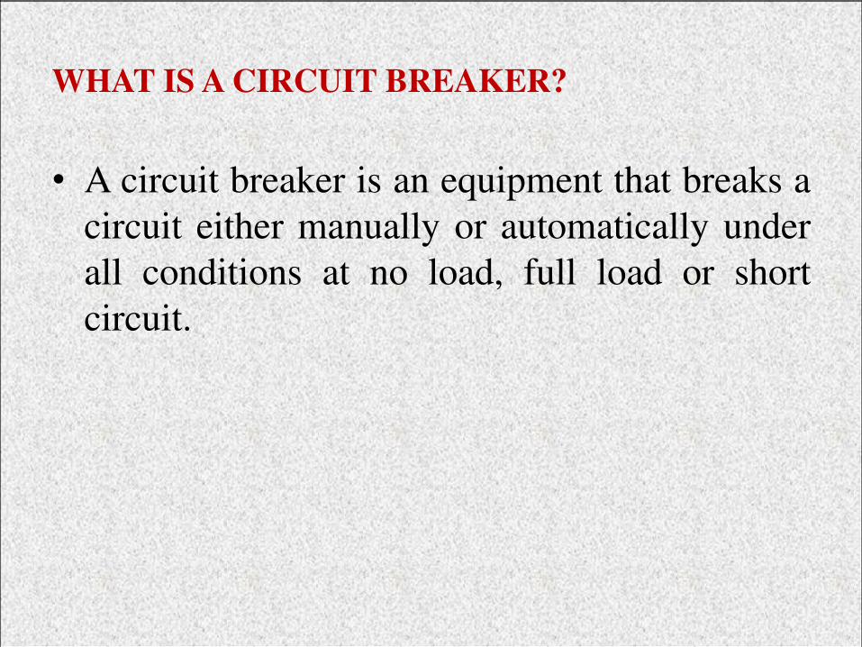
Operating Principle
Two contacts called electrode remains closed under normal operating conditions. When fault occurs on any part of the system, the trip coil of the circuit breaker get energized and contacts are separated.

Arc Phenomenon
• An arc is struck when contacts are separated. The
current is thus able to continue. Thus the main
duty of a circuit breaker is to distinguish the arc
within the shortest possible time.
• The arc provides the low resistance path to the
current and the current in the circuit remains
uninterrupted.

The arc resistance depends upon the following factors. Degree of ionization Length of the arc Cross Section of the arc

Methods of Arc Extinction
High Resistance Method Low Resistance Method

TYPES OF
CIRCUIT
BREAKER
OIL
CIRCUIT
BREAKER
AIR BLAST
CIRCUIT
BREAKER
SF6
CIRCUIT
BREAKER
VACCUM
CIRCUIT
BREAKER

Breaker Used In 132KV Grid
Station
• Oil Circuit Breaker
• Vacuum Circuit breaker
• SF6 Circuit Breaker

Air
cushion
Bulk Oil Circuit breaker

Low Oil Circuit Breaker
Consists of two parts.
Supporting
Chamber.
Circuit-Breaking
chamber( consist
of fixed and
moving contact)

Disadvantages Of Oil Circuit Breaker
• It is inflammable and there is a risk of fire.
• It may form an explosive mixture with air.
• It requires maintenance.
• Absorbs moisture, so dielectric strength reduces.
• Oil leakage problem.
• Oil has to be replaced after some operations because of the carbonization of oil.

Vacuum Circuit Breaker
• Vacuum is used as an arc quenching medium.
• Have greatest insulating strength.
• 10-7 to 10-5 pressure is to be maintained.
• Used in 11KV panel in control room of grid
station.

Vacuum Circuit Breaker

Advantages
• Compact, reliable and have longer life.
• No fire hazards.
• No generation of gas during and after
operation.
• Can interrupt any fault current.
• No noise is produced while operating.
• Require less power for control operation.

SF6 Circuit Breaker
1. Sulphur Hexafluoride (SF6) gas is used as an arc quenching medium.
2. SF6 is an electro-negative gas.
3. It has strong tendency to absorb electrons.
4. When contact are opened in a high pressure flow of SF6 gas, arc produced.
5. Free electron in the arc are captured by the gas.
6. Which build up enough insulation strength to extinguish arc.
7. it is much effective for high power and high voltages services,

Advantages
• Simple construction, less cost.
• SF6 gas is non flammable, non toxic & chemical inert gas.
• Same gas is recirculated in the circuit.
• Maintenance free C.B.
• Ability to interrupt low and high fault current.
• Excellent Arc extinction.

Advantages Of SF6 Over Oil Circuit Breakers
• Short arcing time
• Can interrupt much larger currents
• Gives noiseless operation due to its closed gas circuit
• No moisture problem
• No risk of fire
• No carbon deposits. So no tracking and insulation
problems
• Low maintenance cost

Transformer
An A.C. device used to change high voltage low
current A.C. into low voltage high current A.C. and
vice-versa without changing the frequency
In brief,
1. Transfers electric power from one circuit to another
2. It does so without a change of frequency
3. It accomplishes this by electromagnetic induction
4. Where the two electric circuits are in mutual
inductive influence of each other.

Principle of operation
It is based on principle of MUTUAL
INDUCTION. According to which an e.m.f. is
induced in a coil when current in the
neighbouring coil changes.

Constructional detail : Shell type
• Windings are wrapped around the center leg of a
laminated core.

Core type
• Windings are wrapped around two sides of a laminated square
core.

Sectional view of transformers
Note:
High voltage conductors are smaller cross section conductors
than the low voltage coils

Construction of transformer from
stampings

Core type
Fig1: Coil and laminations of
core type transformer Fig2: Various types of cores

Shell type
• The HV and LV windings are split into no. of sections
• Where HV winding lies between two LV windings
• In sandwich coils leakage can be controlled
Fig: Sandwich windings

Transformer with conservator and
breather

Working of a transformer
1. When current in the primary coil
changes being alternating in
nature, a changing magnetic field
is produced
2. This changing magnetic field gets
associated with the secondary
through the soft iron core
3. Hence magnetic flux linked with
the secondary coil changes.
4. Which induces e.m.f. in the
secondary.

Ideal Transformers
• Zero leakage flux:
-Fluxes produced by the primary and secondary currents
are confined within the core
• The windings have no resistance:
- Induced voltages equal applied voltages
• The core has infinite permeability
- Reluctance of the core is zero
- Negligible current is required to establish magnetic
flux
• Loss-less magnetic core
- No hysteresis or eddy currents

Ideal transformer
V1 – supply voltage ; I1- noload input current ;
V2- output voltgae; I2- output current
Im- magnetising current;
E1-self induced emf ; E2- mutually induced emf

Phasor diagram: Transformer on No-
load

Transformer on load assuming no
voltage drop in the winding
Fig shows the Phasor diagram of a transformer
on load by assuming
1. No voltage drop in the winding
2. Equal no. of primary and secondary turns

Transformer on load
Fig. a: Ideal transformer on load
Fig. b: Main flux and leakage
flux in a transformer

Phasor diagram of transformer with
UPF load

Phasor diagram of transformer with
lagging p.f load

Phasor diagram of transformer with
leading p.f load

Equivalent circuit of a transformer
No load equivalent circuit:

Equivalent circuit parameters referred to
primary and secondary sides respectively

Transferring secondary parameters to
primary side

Transformer Tests
Electrical Machines
•The performance of a transformer can be calculated on the basis of
equivalent circuit
•The four main parameters of equivalent circuit are:
- R01 as referred to primary (or secondary R02)
- the equivalent leakage reactance X01 as referred to primary
(or secondary X02)
- Magnetising susceptance B0 ( or reactance X0)
- core loss conductance G0 (or resistance R0)
•The above constants can be easily determined by two tests
- Oper circuit test (O.C test / No load test)
- Short circuit test (S.C test/Impedance test)
•These tests are economical and convenient
- these tests furnish the result without actually loading the
transformer

In Open Circuit Test the tra sfor er’s secondary winding is open-circuited, and
its primary winding is connected to a full-rated line voltage.
• Usually conducted on
H.V side
• To find
(i) No load loss or core
loss
(ii) No load current Io
which is helpful in
finding Go(or Ro ) and Bo
(or Xo )
2
0
2
00
2
0
oc00
2
0oc
0
0o000
22
000m
00wc
00
0
000
B esusceptanc Exciting &
V
WG econductanc Exciting ;GV W
Y ;YVI
sinI I
cosI I
cos
cosloss Core
GY
V
I
-IIIor
Ior
IV
W
IVW
w
oc
oc
Open-circuit Test
0
0
0
0
0
0
0
0
V
IB
V
IG
I
VX
I
VR
w
w

Short-circuit Test In Short Circuit Test the secondary terminals are short circuited, and the
primary terminals are connected to a fairly low-voltage source
The input voltage is adjusted until the current in the short circuited windings
is equal to its rated value. The input voltage, current and power is
measured.
• Usually conducted on L.V side
• To find
(i) Full load copper loss – to pre determine the efficiency
(ii) Z01 or Z02; X01 or X02; R01 or R02 - to predetermine the voltage
regulation

2
01
2
0101
01
2
sc01
01
2
sc
X
WR
W losscu load Full
RZ
I
VZ
I
RI
sc
sc
sc
sc

Formula: voltage regulation
leadingfor '-' and laggingfor ''
V
sincos
V
Vregulation %
luesprimary va of In terms
leadingfor '-' and laggingfor ''
V
sincos
V
Vregulation %
valuessecondary of In terms
1
10111011
1
'
21
20
20222022
20
220
where
XIRIV
where
XIRIV

Transformer Efficiency
Transformer efficiency is defined as (applies to motors, generators and
transformers):
%100in
out
P
P
%100
lossout
out
PP
P
Types of losses incurred in a transformer:
Copper I2R losses
Hysteresis losses
Eddy current losses
Therefore, for a transformer, efficiency may be calculated using the following:
%100cos
cosx
IVPP
IV
SScoreCu
SS

Losses in a transformer
Core or Iron loss:
Copper loss:

All day efficiency
hours) 24 (kWhin Input
kWhin output
in wattsinput
in wattsput out efficiency commercialordinary
day forall
•All day efficiency is always less than the commercial efficiency

1
Introduction to Energy
Solar Energy

2
The different forms of energy:
Energy can be obtained in number of way. It may be in
the form of
(1) Chemical energy - due to chemical reaction
(2) Electrical energy - due to flow of electron
(3) Heat energy - due to thermal vibration
(4) Light energy - due to radiation of light
(5) Mechanical energy – due to moving parts
(6) Nuclear energy - due to nuclear reaction
The SI unit of energy is Joule (or) N/m.
Definition of Energy: Energy can be defined as the ability
(or) capacity to do work

3
Law of conservation of energy
According to law of conservation of energy, Energy can
neither be created nor destroyed. But, one form of energy
can be converted to another form.
Example: A battery generates electrons from chemical
reactions, which are used to make electrical energy.
A heater convert electrical energy into heat energy.
The human leg converts the chemical energy stored in the
muscles into mechanical energy when you pedal a
bicycle.

4
Category of energy resource
On the basis of availability, the energy resources are
broadly categories as,
• Primary energy resources
• Secondary energy resources
Primary energy: All energy originates from natural sources
such as coal, solar, wind, hydro are called
primary energy resources.
Secondary energy: The energy converted from primary energy
sources. For example, the solar energy
can be converted into electricity

5
Types of Energy sources 1. Conventional energy sources (or) Non-renewable energy sources
2. Non-Conventional energy sources (or) Renewable energy sources
• Generally, non-renewable energy sources come out of the
ground as liquids, gases and solids.
Examples: The conventional (or) Non-renewable energy
sources are Oil, Coal, Petroleum and natural
gas, Nuclear energy
(1) Conventional energy (or) Non-renewable energy
Conventional (or) Non-renewable energy sources are those,
which cannot be replaced continuously.

6
We can obtain renewable energy from the sun, from the
water, from the wind, from crop residues and waste
The types of Non-conventional (or) Renewable energies are
Solar energy Tidal energy
Wind energy Hydro energy
Biomass energy Biofuels
Geothermal Wave Power
Non-Conventional energy (or) Renewable energy
Renewable energy is a source of energy that can never be
exhausted and can be replaced continuously

7
Solar energy
Solar energy comes from the light of the sun, which means it
is a renewable source of energy. We can use the sun light to
create pollution free electricity
The solar cell is the system used to convert the sunlight
energy into electrical energy

8
Solar collectors

9
Areas of the world with high Solar radiation
• The basic resource for all solar energy systems is the
sun.
• Knowledge of the quantity and quality of solar energy
available at a specific location is of prime importance
for the design of any solar energy system

10
• Although the solar radiation is relatively constant outside
the earth's atmosphere, local climate influences can
cause wide variations in available radiation on the
earth’s surface from site to site.
• In addition, the relative motion of the sun with respect to
the earth will allow surfaces with different orientations to
intercept different amounts of solar energy.
• It is the primary task of the solar energy system designer
to determine the amount, quality and timing of the solar
energy available at the site selected for installing a solar
energy conversion system.

1
LVDT
• You’re expected to learn
– Linear Variable Differential Transformer
(LVDT)
• Architecture
• Diagram
• Application

2
LVDT-Inductive T
A reliable and accurate sensing
device that converts linear position
or motion to a proportional
electrical output.

3
LVDT
The cross sectional view of
the DC LVDT at left shows the
built-in signal conditioning
electronics module. The
module is secured with a
potting compound that is not
shown in this drawing

4
Applications of LVDTs

5
Among the advantages of LVDT are as follows:
• It produces a higher output voltages for small
changes in core position.
• Low cost
• Solid and robust -capable of working in a wide
variety of environments.
• No permanent damage to the LVDT if
measurements exceed the designed range.
LVDT

6
LVDT
An inductor is basically a coil of wire
over a “core” (usually ferrous)
It responds to electric or magnetic
fields
A transformer is made of at
least two coils wound over the
core: one is primary and
another is secondary
Primary Secondary
Inductors and tranformers work only for ac signals
A
B
A
B
BAoutVVV

7
EXAMPLES OF LVDT APPLICATION

8
LVDT Operation
Windings are connected “series opposing” polarities of V1 and V2
oppose each other if we trace through
the circuit from terminal A to B.
If the core at the center, V1=V2, Vo=0
When the core is away from center
toward S1, V1 is greater than V2 and
the output voltage Vo will have the
polarity V1.
When the core is away from center
toward S2, V2 is greater than V1 and
the output voltage Vo will have the
polarity V2.

9
LVDT Operation
That is, the output ac voltage inverts
as the core passes the center position
The farther the core moves from
center, the greater the difference in
value between V1 and V2,
consequently the greater the value of
Vo.
Thus, the amplitude of Vo is a function
of the distance the core has moved,
and the polarity or phase indicates
which direction is has moved.
If the core is attached to a moving
object, the LVDT output voltage can be
a measure of the position of the
object.

10
LVDT Operation

11
Example
An ac LVDT has the following data; input 6.3V,
output 5.2V, range ±0.50 cm. Determine:
a) Plot of output voltage versus core position for a
core movement going from +0.45cm to -0.03cm?
b) The output voltage when the core is -0.35cm from
the center?
c) The core movement from center when the output
voltage is -3V?
d) The plot of core position versus output voltages
varying from +4V to -2.5V.

12
Student’s activity for next class
• Based on each measurement, I expect you to gather all the information in the following order – Type sensors
– Architecture
– Operation
– Application
– Diagram
• You will need to prepare study materials/notes based on the information above
• I will collect them by the end of next class (soft copy)

PLC’s Are ... • Similar to a Microcontroller:
– Microprocessor Based
– Onboard Memory for Storing Programs
– Special Programming Language: Ladder Logic
– Input/Output Ports

PLC’s Are...
• Dissimilar to Microcontrollers:
– Intended for Industrial Applications
– I/O Designed to interface with Control Relays
– Emphasis on Maximum Reliability

PLC’s
• Widely Applied in Every Industry
• Were Developed to Simplify the
Implementation of Control Automation
Systems in Plants and Assembly Lines
• Designed to Minimize the Number of
Control Relays in a Process and Maximize
the Ways Relays can be Used
• First Applied to Automobile Industry in the
Late 1960’s
• Flexible, Reliable and Low Cost

PLC Components


I/O Modules
• Input Modules: Input Signals can be AC or
DC, Analog or Digital
• Output Modules: Outputs are either AC or
DC Analog Signals (Although it is possible
to ‘Construct’ Digital Outputs) • Modern PLC’s have Expansion Ports to
Increase the Number of Available Inputs
and Outputs

Examples of I/O Signals
• Inputs:
– Pushbutton (Energizing or Grounding an Input)
– Relay Contact Output
– DC Voltage Level
– Digital Logic Signal (+5V or 0 V, etc)
• Outputs:
– 24 V ac
– 120 V ac
– 120 Vdc
– etcetera

PLC’s Use Ladder Logic
• Ladder Logic Diagrams Provide a Method
to Symbolically Show How Relay Control
Schemes are Implemented
• Relay Contacts and Coils, Inputs and
Outputs lie on “Rungs” Between the Positive and Ground Rails

Example of Ladder Diagram

Relays
• In General, Relays Transform a Control
Signal into a Control Action
• Relays Provide:
– Isolation Between Input and Output
– Leverage (Small Signal Can Control Large
Action)
– Automation (Minimize Human Interaction with
a Control Process)

Relay Applications
• Relays can be Designed to Perform Many
Functions
– Detect Out of Limit Conditions on Voltages
and Currents
– Start Motors
– Prevent Motors from Over Heating
– Control Assembly Lines
– Adjust Lighting

PLC Timers and Motor
Protection

Industrial Communications
• RS-422 (EIA 422): Asynchronous Serial
Communications , similar in many respects
to RS-232
• Faster (up to 100 Kbps) than RS-232
• Better Noise Immunity
– Differential (Balanced signal) Protocol
– Makes use of Twisted Pair lines - 1 pair for
transmit, one pair for receive (4 Lines vs. 3)

EIA-422 Basics
• Can be 1 Master Transmitter feeding up to
10 Slave Receivers
• Can be Peer-to-Peer, like RS-232
• Data is sent and received via Differential
Ports - Common Mode Rejection (Noise
common to both inputs is attenuated)
• Twisted Pair also reduces EMI at low cost

EIA 485 (RS-485) • More Modern, Faster and Flexible (supports TCP/IP)
• Since it uses a differential balanced line over twisted
pair (like EIA-422), it can span relatively large
distances (up to 4000 feet or just over 1200 metres).
• In contrast to EIA-422, which has a single driver
circuit which cannot be switched off, EIA-485 drives
need to be put in transmit mode explicitly by
asserting a signal to the driver. This allows EIA-485
to implement linear topologies using only two lines.

IEEE 802.3 (Ethernet)
• Star Topology (Hub and spokes)
• Standard for computer networks since the
1990’s
• Becoming more and more popular in
Industrial settings
• Uses twisted pair data cables terminated in
8P8C (sometimes incorrectly called RJ45)
modular plugs, wired according to TIA/EIA-
568-B

Twisted Pair Cables
• Twisting a pair of wires that act as a communication
channel will:
– Minimize the loop area between the pair (minimize the
self-inductance and capacitance)
– Which in turn tends to cancel out much of the
electromagnetic interference from external sources and
crosstalk from adjacent pairs
– Improve the efficiency of the channel

PLC Special Features
• Time Delay Relays
• Counter Relays
• Special Functions
• User Defined Functions
• Special Bits

Time Delay Relays
• When TD Relay Pick-Up Coil is Energized,
a Delay is Initiated
• Normally Open Contacts Wait to Close
until Delay is Completed
• Normally Closed Contacts Wait to Open
until Delay is Completed
• Very Useful for Creating a Sequence of
Control Events

Making Use of Delays • Delay Motor Start While Alarm Sounds for
Safety

Counters • Counter Relays must “Count” a pre-
determined number of events before
changing contact status
• Can Count Up (UpCounter) or Count Down
(DownCounter)
• e.g. An UpCounter is set to 8 and is
programmed to detect every occurrence of a
5 Volt pulse. When it has detected 8 such
occurrences, the NO Contacts close and the
NC contacts open.
• Great for making Real-Time Clocks, etc

Special Functions
• Modern PLCs can perform many Math and
Logic Functions without additional Ladder
Logic Programming
– Differentiation, Integration
– +, -, *, /
– Boolean Logic Functions (AND, NOT, OR)
– Master Control Functions (Reset, etc)

Motor Protection
• Essential Part of Motor Control
• Protect against:
– Under Voltage
– Under Frequency (AC Machines Only)
– Over Current
– Over Heating
– Over Speed
– Over Load

Motor Protection Schemes
• Incorporated Directly in Ladder Logic
Control Schemes

ELECTRIC TRACTION

INTRODUCTION:
The locomotion in which the driving force is
obtained from electric motor is called the electric
traction system.
There are various system of electric traction
existing such as electric train, trolley buses,
diesel-electric vehicles and gas turbine electric
vehicles
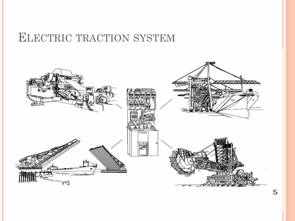
ELECTRIC TRACTION SYSTEM

MAJOR CLASSIFICATIONS OF
TRACTION
Non-electric traction:
examples
steam engine drive
ic engine drive
Electric traction:
examples
diesel electric drive
gas turbine electric drive

REQUIREMENTS OF AN IDEAL TRACTION
SYSTEM
The starting tractive effort should be high so as
to have rapid acceleration.
The wear on the track should be minimum.
The equipments should be capable of
withstanding large temporary loads.
Speed control should be easy.
Pollution free.
Low initial and maintenance cost.
The locomotive should be self contain and able to
run on any route.

MERITS OF ELECTRIC TRACTION
High starting torque.
Less maintenance cost
Cheapest method of traction
Rapid acceleration and braking
Less vibration
Free from smoke and flue gases hence used for
underground and tubular railway.

DEMERITS OF ELECTRIC TRACTION
High capital cost.
Problem of supply failure.
The electrically operated vehicles have to move
on guided track only.
Additional equipment is required for achieving
electric braking and control.

DIFFERENT SYSTEMS OF TRACTION:
Direct steam engine drive
Direct IC engine drive
Steam electric drive
IC engine electric drive
Petrol electric traction
Battery electric drive
Electric drive

IC ENGINE ELECTRIC DRIVES

SUPPLY SYSTEMS FOR ELECTRIC
TRACTION:
D.C system
A.C system
Single phase
Three phase
Composite system
Single phase AC to DC
Single phase to three phase

SPEED TIME CURVE FOR TRAIN MOVEMENT
Acceleration
Constant acceleration
Speed curve running
Free run or constant speed period
Coasting period
Retardation or braking period

TYPICAL SPEED TIME CURVES FOR
DIFFERENT SERVICES
Urban or city services
Sub urban services
Main line services
TYPES OF SPEED IN TRACTION
crest speed
Average speed
Schedule speed
FACTORS AFFECTING ENERGY
CONSUMPTION
Distance between the stops.
Train resistance
Acceleration and retardation.
Gradient
train equipment.

TRACTION MOTORS
DC series motor
Ac series motor
Three phase induction motor

TRACTION MOTOR ELECTRICAL FEATURES
High starting torque
Simple speed control
Regenerative braking
Better commutation
Capability of withstanding voltage fluctuations.
MECHANICAL FEATURES
Light in weight.
Small space requirement.
Robust and should be able to withstand
vibration.

TRACTION MOTOR CONTROL
Rheostat control
Series parallel control
Field control
Buck and boost method
Metadyne control
Thyristor control
Phase control
Chopper control

BRAKING
ELECTRIC BRAKING
Plugging or reverse current braking
Rheostatic braking
Regenerative braking
DC shunt motor
DC series motor
Induction motor
MECHANICAL BRAKING
Compressed air brakes
Vacuum brakes
MAGNETIC TRACK BRAKES

RECENT TRENDS IN ELECTRIC TRACTION
Tap changer control
Thyristor control
Chopper control
Micro processor control

MICRO PROCESSOR CONTROL

QUESTIONS ?

“If fail to Plan, you plan to fail”
THANK
YOU