Embed Size (px)
Citation preview
Crystal Structure Crystal structures may be conveniently specified by describing the arrangement within the solid
of a small representative group of atoms or molecules, called the „unit cell.‟ By multiplying
identical unit cells in three directions, the location of all the particles in the crystal is determined.
In nature, 14 different types of crystal structures or lattices are found. The simplest crystalline
unit cell to picture is the cubic, where the atoms are lined up in a square, 3D grid. The unit cell is
simply a box with an atom at each corner. Simple cubic crystals are relatively rare, mostly
because they tend to easily distort. However, many crystals form body-centered-cubic (bcc) or
face-centered-cubic (fcc) structures, which are cubic with either an extra atom centered in the
cube or centered in each face of the cube. Most metals form bcc, fcc or Hexagonal Close Packed
(hpc) structures; however, the structure can change depending on temperature. These three
structures will be discussed in more detail on the following page.
Crystalline structure is important because it contributes to the properties of a material. For
example, it is easier for planes of atoms to slide by each other if those planes are closely packed.
Therefore, lattice structures with closely packed planes allow more plastic deformation than
those that are not closely packed. Additionally, cubic lattice structures allow slippage to occur
more easily than non-cubic lattices. This is because their symmetry provides closely packed
planes in several directions. A face-centered cubic crystal structure will exhibit more ductility
(deform more readily under load before breaking) than a body-centered cubic structure. The bcc
lattice, although cubic, is not closely packed and forms strong metals. Alpha-iron and tungsten
have the bcc form. The fcc lattice is both cubic and closely packed and forms more ductile
materials. Gamma-iron, silver, gold, and lead have fcc structures. Finally, HCP lattices are
closely packed, but not cubic. HCP metals like cobalt and zinc are not as ductile as the fcc
metals.
Primary Metallic Crystalline Structures (BCC, FCC, HCP)
There are 14 different types of crystal unit cell structures or lattices are
found in nature. However most metals and many other solids have unit cell
structures described as body center cubic (bcc), face centered cubic (fcc) or
Hexagonal Close Packed (hcp). Since these structures are most common,
they will be discussed in more detail.
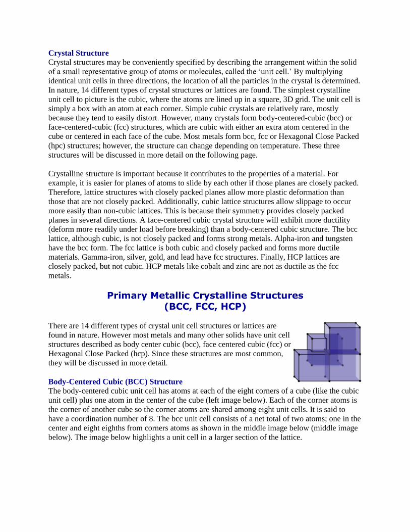
Body-Centered Cubic (BCC) Structure The body-centered cubic unit cell has atoms at each of the eight corners of a cube (like the cubic
unit cell) plus one atom in the center of the cube (left image below). Each of the corner atoms is
the corner of another cube so the corner atoms are shared among eight unit cells. It is said to
have a coordination number of 8. The bcc unit cell consists of a net total of two atoms; one in the
center and eight eighths from corners atoms as shown in the middle image below (middle image
below). The image below highlights a unit cell in a larger section of the lattice.
The bcc arrangement does not allow the atoms to pack together as closely as the fcc or hcp
arrangements. The bcc structure is often the high temperature form of metals that are close-
packed at lower temperatures. The volume of atoms in a cell per the total volume of a cell is
called the packing factor. The bcc unit cell has a packing factor of 0.68.
Some of the materials that have a bcc structure include lithium, sodium, potassium, chromium,
barium, vanadium, alpha-iron and tungsten. Metals which have a bcc structure are usually harder
and less malleable than close-packed metals such as gold. When the metal is deformed, the
planes of atoms must slip over each other, and this is more difficult in the bcc structure. It should
be noted that there are other important mechanisms for hardening materials, such as introducing
impurities or defects which make slipping more difficult. These hardening mechanisms will be
discussed latter.
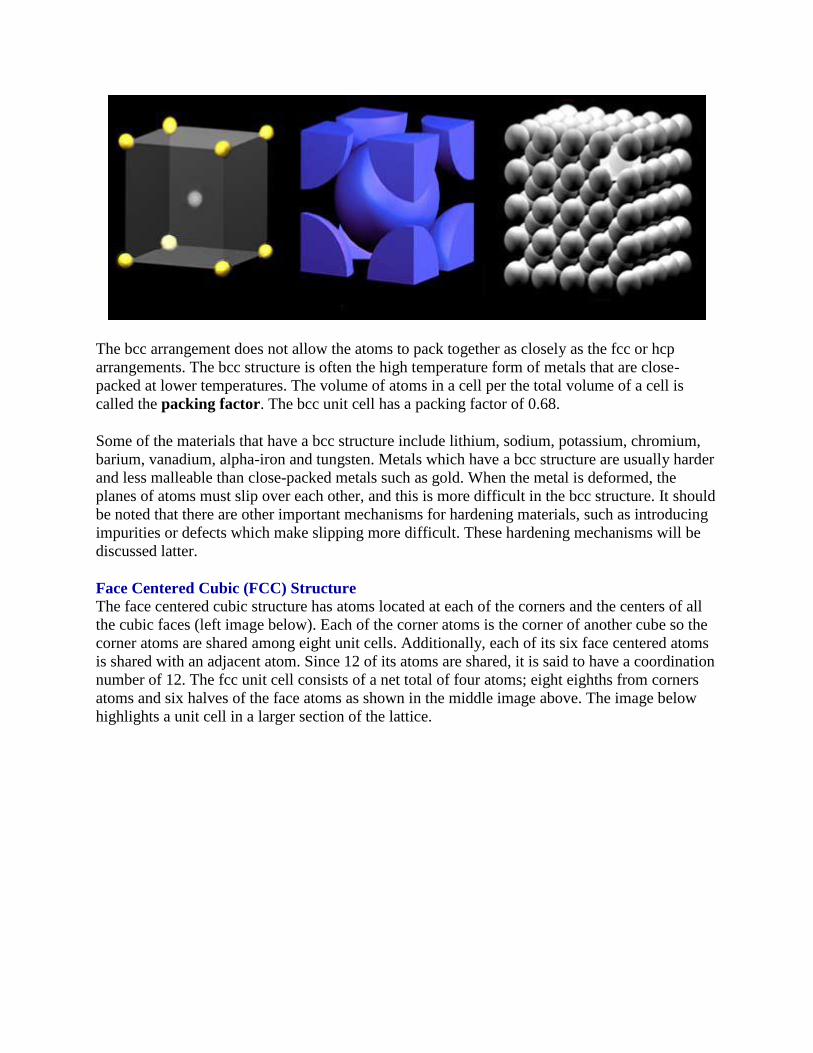
Face Centered Cubic (FCC) Structure The face centered cubic structure has atoms located at each of the corners and the centers of all
the cubic faces (left image below). Each of the corner atoms is the corner of another cube so the
corner atoms are shared among eight unit cells. Additionally, each of its six face centered atoms
is shared with an adjacent atom. Since 12 of its atoms are shared, it is said to have a coordination
number of 12. The fcc unit cell consists of a net total of four atoms; eight eighths from corners
atoms and six halves of the face atoms as shown in the middle image above. The image below
highlights a unit cell in a larger section of the lattice.
In the fcc structure (and the hcp structure) the atoms can pack closer together than they can in the
bcc structure. The atoms from one layer nest themselves in the empty space between the atoms
of the adjacent layer. To picture packing arrangement, imagine a box filled with a layer of balls
that are aligned in columns and rows. When a few additional balls are tossed in the box, they will
not balance directly on top of the balls in the first layer but instead will come to rest in the pocket
created between four balls of the bottom layer. As more balls are added they will pack together
to fill up all the pockets. The packing factor (the volume of atoms in a cell per the total volume
of a cell) is 0.74 for fcc crystals. Some of the metals that have the fcc structure include
aluminum, copper, gold, iridium, lead, nickel, platinum and silver.
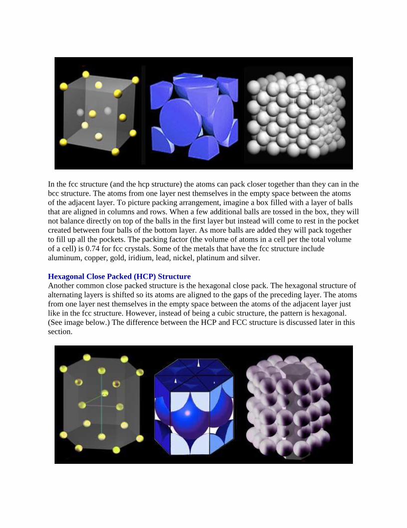
Hexagonal Close Packed (HCP) Structure Another common close packed structure is the hexagonal close pack. The hexagonal structure of
alternating layers is shifted so its atoms are aligned to the gaps of the preceding layer. The atoms
from one layer nest themselves in the empty space between the atoms of the adjacent layer just
like in the fcc structure. However, instead of being a cubic structure, the pattern is hexagonal.
(See image below.) The difference between the HCP and FCC structure is discussed later in this
section.
The hcp structure has three layers of atoms. In each the top and bottom layer, there are six atoms
that arrange themselves in the shape of a hexagon and a seventh atom that sits in the middle of
the hexagon. The middle layer has three atoms nestle in the triangular "grooves" of the top and
bottom plane. Note that there are six of these "grooves" surrounding each atom in the hexagonal
plane, but only three of them can be filled by atoms.
As shown in the middle image above, there are six atoms in the hcp unit cell. Each of the 12
atoms in the corners of the top and bottom layers contribute 1/6 atom to the unit cell, the two
atoms in the center of the hexagon of both the top and bottom layers each contribute atom and
each of the three atom in the middle layer contribute 1 atom. The image on the right above
attempts to show several hcp unit cells in a larger lattice.
The coordination number of the atoms in this structure is 12. There are six nearest neighbors in
the same close packed layer, three in the layer above and three in the layer below. The packing
factor is 0.74, which is the same as the fcc unit cell. The hcp structure is very common for
elemental metals and some examples include beryllium, cadmium, magnesium, titanium, zinc
and zirconium.
Crystallographic Planes & Directions • It is often necessary to be able to specify
certain directions
and planes in crystals.
• Many material properties and processes vary
with direction
in the crystal.
• Directions and planes are described using three
integers -
Miller Indices
Miller Indices (hkl)
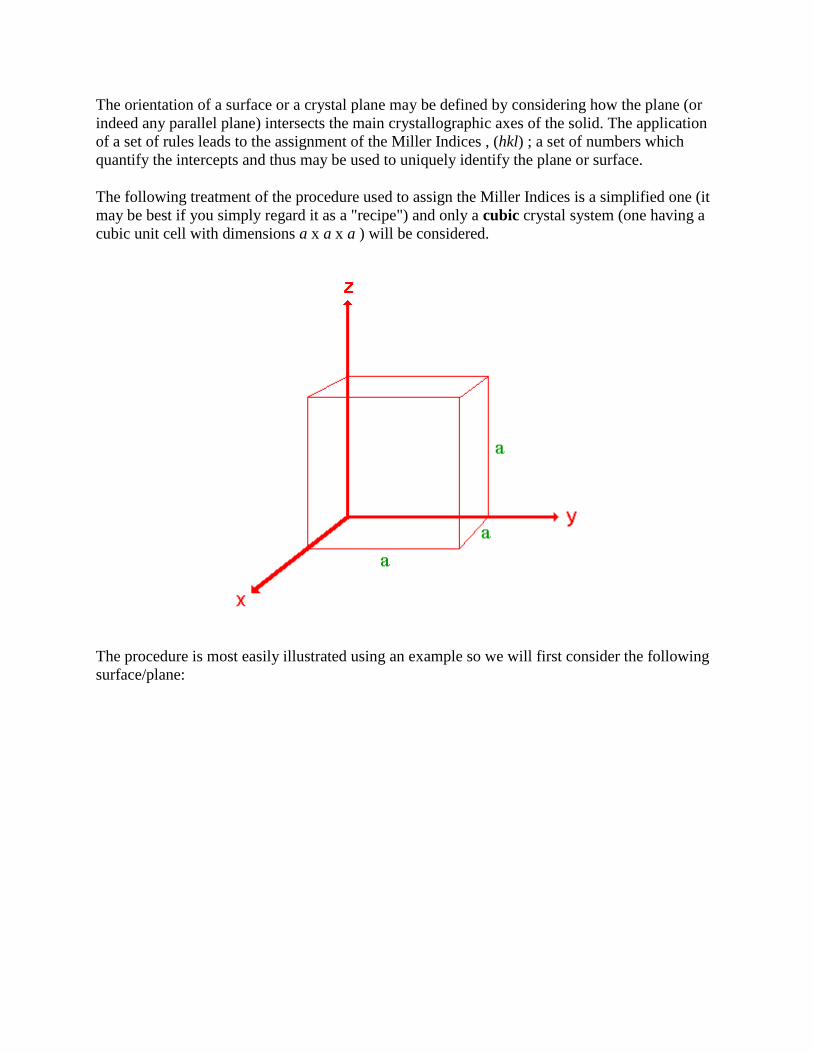
The orientation of a surface or a crystal plane may be defined by considering how the plane (or
indeed any parallel plane) intersects the main crystallographic axes of the solid. The application
of a set of rules leads to the assignment of the Miller Indices , (hkl) ; a set of numbers which
quantify the intercepts and thus may be used to uniquely identify the plane or surface.
The following treatment of the procedure used to assign the Miller Indices is a simplified one (it
may be best if you simply regard it as a "recipe") and only a cubic crystal system (one having a
cubic unit cell with dimensions a x a x a ) will be considered.
The procedure is most easily illustrated using an example so we will first consider the following
surface/plane:
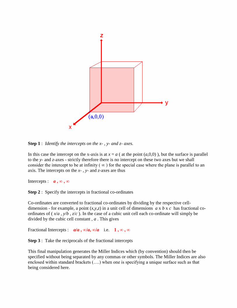
Step 1 : Identify the intercepts on the x- , y- and z- axes.
In this case the intercept on the x-axis is at x = a ( at the point (a,0,0) ), but the surface is parallel
to the y- and z-axes - strictly therefore there is no intercept on these two axes but we shall
consider the intercept to be at infinity ( ∞ ) for the special case where the plane is parallel to an
axis. The intercepts on the x- , y- and z-axes are thus
Intercepts : a , ∞ , ∞
Step 2 : Specify the intercepts in fractional co-ordinates
Co-ordinates are converted to fractional co-ordinates by dividing by the respective cell-
dimension - for example, a point (x,y,z) in a unit cell of dimensions a x b x c has fractional co-
ordinates of ( x/a , y/b , z/c ). In the case of a cubic unit cell each co-ordinate will simply be
divided by the cubic cell constant , a . This gives
Fractional Intercepts : a/a , ∞/a, ∞/a i.e. 1 , ∞ , ∞
Step 3 : Take the reciprocals of the fractional intercepts
This final manipulation generates the Miller Indices which (by convention) should then be
specified without being separated by any commas or other symbols. The Miller Indices are also
enclosed within standard brackets (….) when one is specifying a unique surface such as that
being considered here.
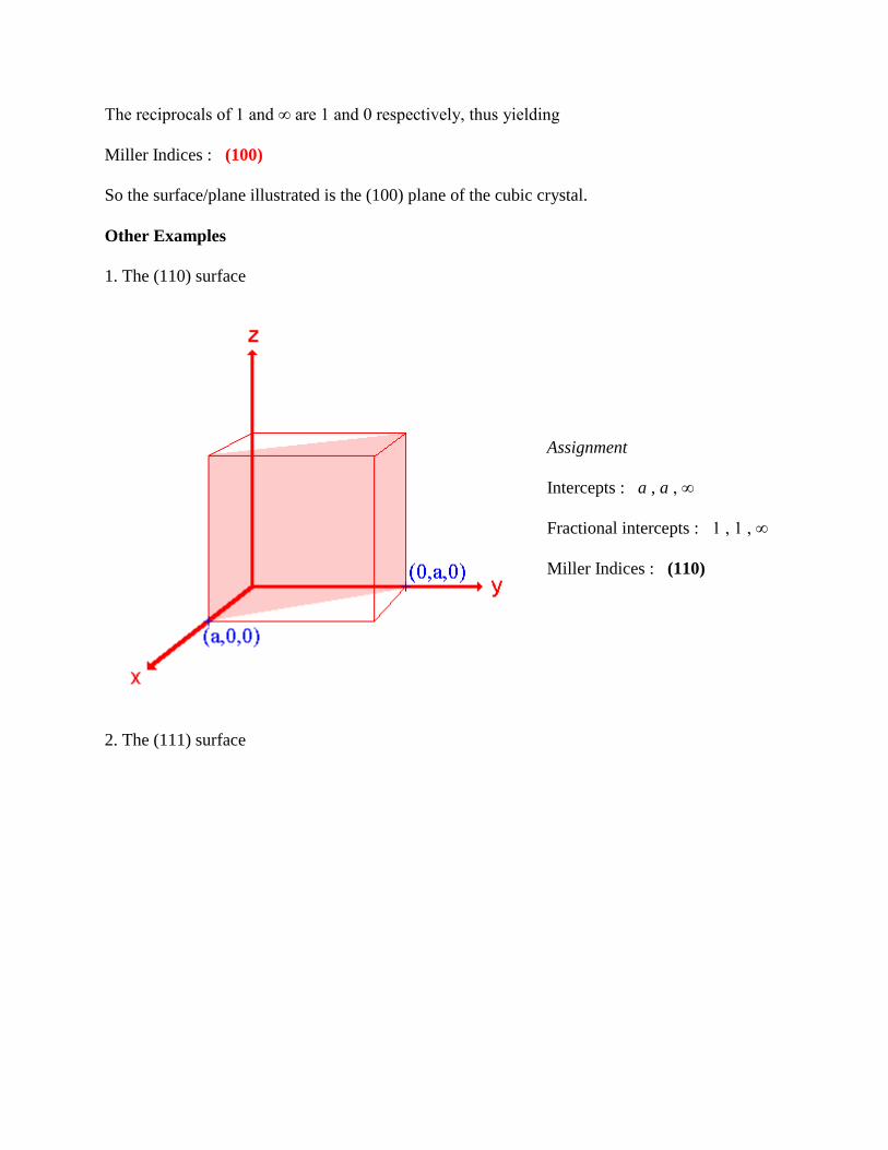
The reciprocals of 1 and ∞ are 1 and 0 respectively, thus yielding
Miller Indices : (100)
So the surface/plane illustrated is the (100) plane of the cubic crystal.
Other Examples
1. The (110) surface
Assignment
Intercepts : a , a , ∞
Fractional intercepts : 1 , 1 , ∞
Miller Indices : (110)
2. The (111) surface
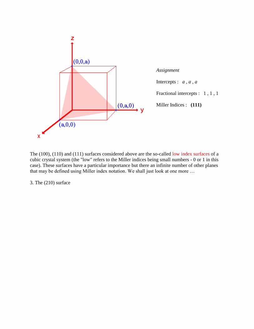
Assignment
Intercepts : a , a , a
Fractional intercepts : 1 , 1 , 1
Miller Indices : (111)
The (100), (110) and (111) surfaces considered above are the so-called low index surfaces of a
cubic crystal system (the "low" refers to the Miller indices being small numbers - 0 or 1 in this
case). These surfaces have a particular importance but there an infinite number of other planes
that may be defined using Miller index notation. We shall just look at one more …
3. The (210) surface
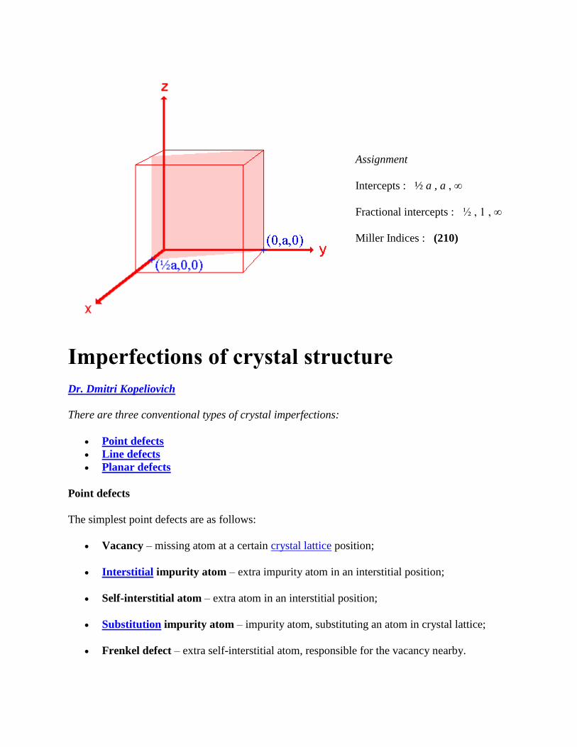
Assignment
Intercepts : ½ a , a , ∞
Fractional intercepts : ½ , 1 , ∞
Miller Indices : (210)
Imperfections of crystal structure
Dr. Dmitri Kopeliovich
There are three conventional types of crystal imperfections:
Point defects
Line defects
Planar defects
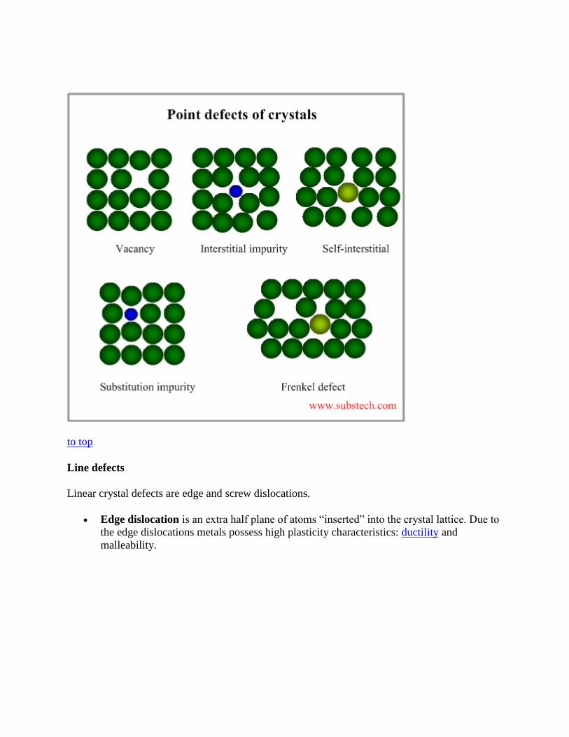
Point defects
The simplest point defects are as follows:
Vacancy – missing atom at a certain crystal lattice position;
Interstitial impurity atom – extra impurity atom in an interstitial position;
Self-interstitial atom – extra atom in an interstitial position;
Substitution impurity atom – impurity atom, substituting an atom in crystal lattice;
Frenkel defect – extra self-interstitial atom, responsible for the vacancy nearby.
to top
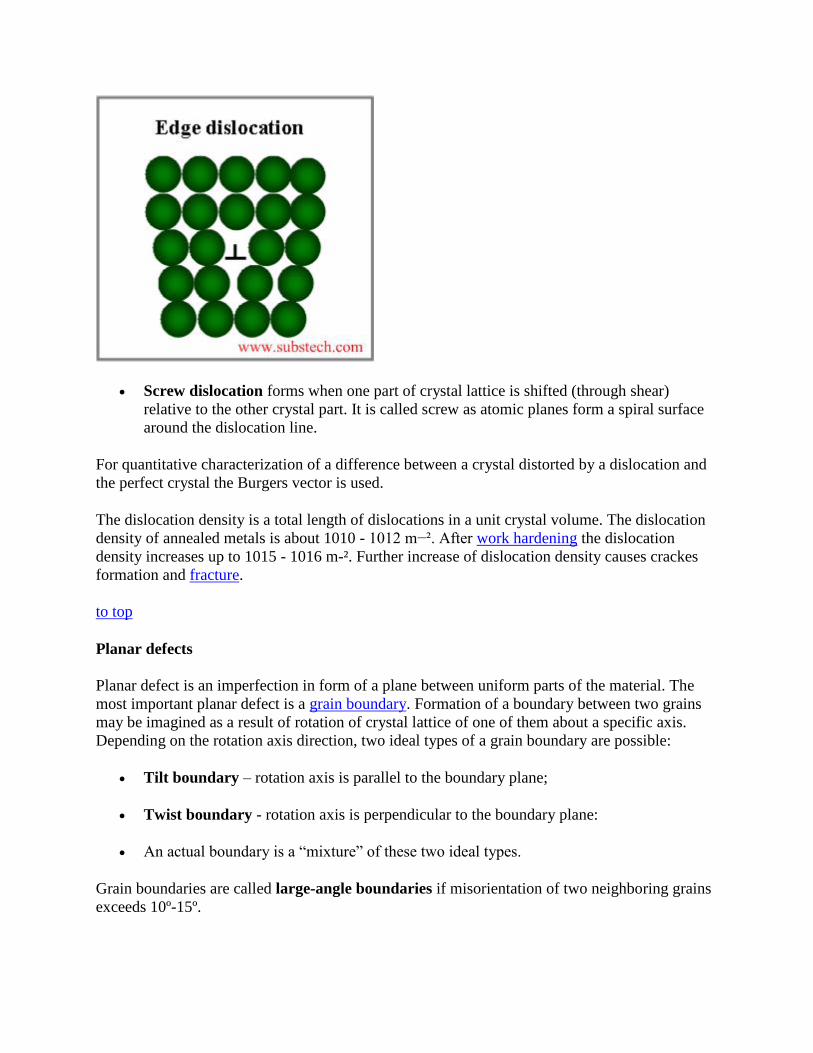
Line defects
Linear crystal defects are edge and screw dislocations.
Edge dislocation is an extra half plane of atoms “inserted” into the crystal lattice. Due to
the edge dislocations metals possess high plasticity characteristics: ductility and
malleability.
Screw dislocation forms when one part of crystal lattice is shifted (through shear)
relative to the other crystal part. It is called screw as atomic planes form a spiral surface
around the dislocation line.
For quantitative characterization of a difference between a crystal distorted by a dislocation and
the perfect crystal the Burgers vector is used.
The dislocation density is a total length of dislocations in a unit crystal volume. The dislocation
density of annealed metals is about 1010 - 1012 m−². After work hardening the dislocation
density increases up to 1015 - 1016 m-². Further increase of dislocation density causes crackes
formation and fracture.
to top
Planar defects
Planar defect is an imperfection in form of a plane between uniform parts of the material. The
most important planar defect is a grain boundary. Formation of a boundary between two grains
may be imagined as a result of rotation of crystal lattice of one of them about a specific axis.
Depending on the rotation axis direction, two ideal types of a grain boundary are possible:
Tilt boundary – rotation axis is parallel to the boundary plane;
Twist boundary - rotation axis is perpendicular to the boundary plane:
An actual boundary is a “mixture” of these two ideal types.
Grain boundaries are called large-angle boundaries if misorientation of two neighboring grains
exceeds 10º-15º.
Grain boundaries are called small-angle boundaries if misorientation of two neighboring grains
is 5º or less.
Grains, divided by small-angle boundaries are also called subgrains.
Grain boundaries accumulate crystal lattice defects (vacancies, dislocations) and other
imperfections, therefore they effect on the metallurgical processes, occurring in alloys and their
properties.
Since the mechanism of metal deformation is a motion of crystal dislocations through the lattice,
grain boundaries, enriched with dislocations, play an important role in the deformation process.
Diffusion along grain boundaries is much faster, than throughout the grains.
Segregation of impurities in form of precipitating phases in the boundary regions causes a form
of corrosion, associated with chemical attack of grain boundaries. This corrosion is called
Intergranular corrosion.
Crystal Defects
A perfect crystal, with every atom of the same type in the correct position, does not exist. All
crystals have some defects. Defects contribute to the mechanical properties of metals. In fact,
using the term “defect” is sort of a misnomer since these features are commonly intentionally
used to manipulate the mechanical properties of a material. Adding alloying elements to a metal
is one way of introducing a crystal defect. Nevertheless, the term “defect” will be used, just keep
in mind that crystalline defects are not always bad. There are basic classes of crystal defects:
point defects, which are places where an atom is missing or irregularly placed in the
lattice structure. Point defects include lattice vacancies, self-interstitial atoms,
substitution impurity atoms, and interstitial impurity atoms
linear defects, which are groups of atoms in irregular positions. Linear defects are
commonly called dislocations.
planar defects, which are interfaces between homogeneous regions of the material. Planar
defects include grain boundaries, stacking faults and external surfaces.
It is important to note at this point that plastic deformation in a material occurs due to the
movement of dislocations (linear defects). Millions of dislocations result for plastic forming
operations such as rolling and extruding. It is also important to note that any defect in the regular
lattice structure disrupts the motion of dislocation, which makes slip or plastic deformation more
difficult. These defects not only include the point and planer defects mentioned above, and also
other dislocations. Dislocation movement produces additional dislocations, and when
dislocations run into each other it often impedes movement of the dislocations. This drives up the
force needed to move the dislocation or, in other words, strengthens the material. Each of the
crystal defects will be discussed in more detail in the following pages.
GRAIN SIZE DETERIMINATION
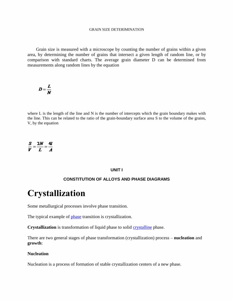
Grain size is measured with a microscope by counting the number of grains within a given
area, by determining the number of grains that intersect a given length of random line, or by
comparison with standard charts. The average grain diameter D can be determined from
measurements along random lines by the equation
where L is the length of the line and N is the number of intercepts which the grain boundary makes with
the line. This can be related to the ratio of the grain-boundary surface area S to the volume of the grains,
V, by the equation
UNIT I
CONSTITUTION OF ALLOYS AND PHASE DIAGRAMS
Crystallization
Some metallurgical processes involve phase transition.
The typical example of phase transition is crystallization.
Crystallization is transformation of liquid phase to solid crystalline phase.
There are two general stages of phase transformation (crystallization) process – nucleation and
growth:
Nucleation
Nucleation is a process of formation of stable crystallization centers of a new phase.
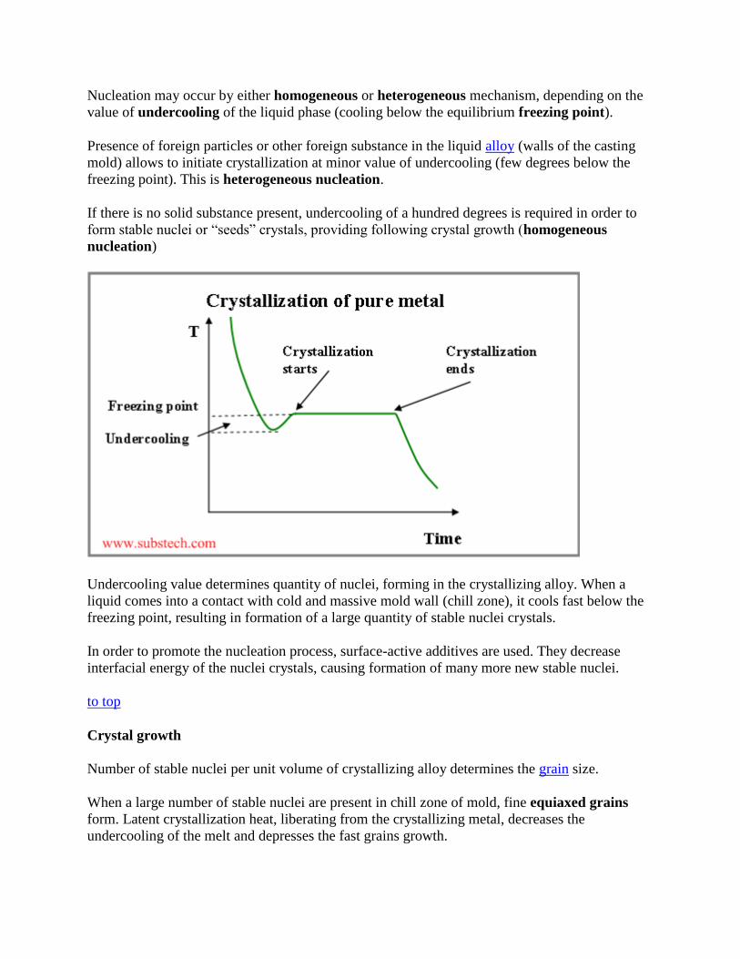
Nucleation may occur by either homogeneous or heterogeneous mechanism, depending on the
value of undercooling of the liquid phase (cooling below the equilibrium freezing point).
Presence of foreign particles or other foreign substance in the liquid alloy (walls of the casting
mold) allows to initiate crystallization at minor value of undercooling (few degrees below the
freezing point). This is heterogeneous nucleation.
If there is no solid substance present, undercooling of a hundred degrees is required in order to
form stable nuclei or “seeds” crystals, providing following crystal growth (homogeneous
nucleation)
Undercooling value determines quantity of nuclei, forming in the crystallizing alloy. When a
liquid comes into a contact with cold and massive mold wall (chill zone), it cools fast below the
freezing point, resulting in formation of a large quantity of stable nuclei crystals.
In order to promote the nucleation process, surface-active additives are used. They decrease
interfacial energy of the nuclei crystals, causing formation of many more new stable nuclei.
to top
Crystal growth
Number of stable nuclei per unit volume of crystallizing alloy determines the grain size.
When a large number of stable nuclei are present in chill zone of mold, fine equiaxed grains
form. Latent crystallization heat, liberating from the crystallizing metal, decreases the
undercooling of the melt and depresses the fast grains growth.
At this stage some of small grains, having favorable growth axis, start to grow in the direction
opposite to the direction of heat flow. As a result columnar crystals (columnar grains) form.
Contrary to the pure metals, in alloys different type of undercooling takes place. It is called
constitutional undercooling.
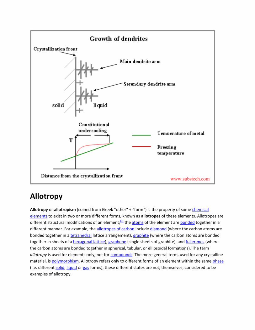
Constitutional undercooling
Since solubility of an alloying element in solid is lower, than in liquid at the same temperature,
this element (solute) is rejected by the solidifying metal to the liquid phase, enriching the region
of liquid adjacent to the crystallization front.
For the most of the alloys: the higher the concentration of alloying element in the alloy, the lower
its liquidus temperature (temperature at which crystallization of the alloy starts).
Thus crystallization temperature of the liquid, adjacent to the crystallization front, rises with
increasing the distance from the front surface. Therefore there is a layer of the liquid, where its
temperature is lower, than its crystallization temperature. This is the region of constitutional
undercooling (see the figure below).
Dendrites
If a protruding finger forms on the solidifying surface, its tip may reach the region of
constitutional undercooling . In this case the protuberance starts accelerated growth, forming the
main dendrite arms. Under certain conditions the same process may occur on the surface of the
main dendrite arms, causing branching off the secondary arms and then arms of higher orders.
Allotropy
Allotropy or allotropism (coined from Greek "other" + "form") is the property of some chemical
elements to exist in two or more different forms, known as allotropes of these elements. Allotropes are
different structural modifications of an element;[1] the atoms of the element are bonded together in a
different manner. For example, the allotropes of carbon include diamond (where the carbon atoms are
bonded together in a tetrahedral lattice arrangement), graphite (where the carbon atoms are bonded
together in sheets of a hexagonal lattice), graphene (single sheets of graphite), and fullerenes (where
the carbon atoms are bonded together in spherical, tubular, or ellipsoidal formations). The term
allotropy is used for elements only, not for compounds. The more general term, used for any crystalline
material, is polymorphism. Allotropy refers only to different forms of an element within the same phase
(i.e. different solid, liquid or gas forms); these different states are not, themselves, considered to be
examples of allotropy.
solid solution A solid solution is formed when two metals are completely soluble in liquid state and also
completely soluble in solid state. In other words, when homogeneous mixtures of two or
more kinds of atoms (of metals) occur in the solid state, they are known as solid solutions.
The more abundant atomic form is referred as solvent and the less abundant atomic form
is referred as solute. For example sterling silver (92.5 percent silver and the remainder
copper) is a solid solution of silver and copper. In this case silver atoms are solvent atoms
whereas copper atoms are solute atoms. Another example is brass. Brass is a solid
solution of copper (64 percent) and zinc (36 percent). In this case copper atoms are
solvent atoms whereas zinc atoms are solute atoms.
5.1 TYPES OF SOLID SOLUTIONS Solid solutions are of two types. They are
(a) Substitutional solid solutions.
(b) Interstitial solid solutions.
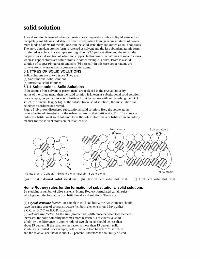
5.1.1 Substitutional Solid Solutions If the atoms of the solvent or parent metal are replaced in the crystal lattice by
atoms of the solute metal then the solid solution is known as substitutional solid solution.
For example, copper atoms may substitute for nickel atoms without disturbing the F.C.C.
structure of nickel (Fig. 5.1a). In the substitutional solid solutions, the substitution can
be either disordered or ordered.
Figure 5.1b shows disordered substitutional solid solution. Here the solute atoms
have substituted disorderly for the solvent atoms on their lattice site. Fig. 5.1c shows an
ordered substitutional solid solution. Here the solute atoms have substituted in an orderly
manner for the solvent atoms on their lattice site.
Hume Rothery rules for the formation of substitutional solid solutions By studying a number of alloy systems, Hume Rothery formulated certain rules
which govern the formation of substitutional solid solutions. These are:
(a) Crystal structure factor: For complete solid solubility, the two elements should
have the same type of crystal structure i.e., both elements should have either
F.C.C. or B.C.C. or H.C.P. structure.
(b) Relative size factor: As the size (atomic radii) difference between two elements
increases, the solid solubility becomes more restricted. For extensive solid
solubility the difference in atomic radii of two elements should be less than
about 15 percent. If the relative size factor is more than 15 percent, solid
solubility is limited. For example, both silver and lead have F.C.C. structure
and the relative size factor is about 20 percent. Therefore the solubility of lead

in solid silver is about 1.5 percent and the solubility of silver in solid lead is
about 0.1 percent. Copper and nickel are completely soluble in each other in
all proportions. They have the same type of crystal structure (F.C.C.) and differ
in atomic radii by about 2 percent.
(c) Chemical affinity factor: Solid solubility is favoured when the two metals
have lesser chemical affinity. If the chemical affinity of the two metals is
greater then greater is the tendency towards compound formation. Generally,
if the two metals are separated in the periodic table widely then they possess
greater chemical affinity and are very likely to form some type of compound
instead of solid solution.
(d) Relative valence factor: It is found that a metal of lower valence tends to
dissolve more of a metal of higher valence than vice versa. For example in
aluminium-nickel alloy system, nickel (lower valance) dissolves 5 percent aluminium
but aluminium (higher valence) dissolves only 0.04 percent nickel.
Interstitial Solid Solutions In interstitial solid solutions, the solute atom does not displace a solvent atom, but
rather it enters one of the holes or interstices between the solvent atoms. An excellent
example is iron-carbon system which is shown in Fig. 5.2
In this system the carbon (solute atom) atom occupies an interstitial position between
iron (solvent atom) atoms. Normally, atoms which have atomic radii less than one angstrom
are likely to form interstitial solid solutions. Examples are atoms of carbon (0.77 A°),
nitrogen (0.71 A°), hydrogen (0.46 A°), Oxygen (0.60 A°) etc.
Gibbs' Phase Rule
The Phase Rule describes the possible number of degrees of freedom in a (closed) system at
equilibrium, in terms of the number of separate phases and the number of chemical constituents
in the system. It was deduced from thermodynamic principles by J. W. Gibbs in the 1870s.
The Degrees of Freedom [F] is the number of independent intensive variables (i.e. those that are
independent of the quantity of material present) that need to be specified in value to fully
determine the state of the system. Typical such variables might be temperature, pressure, or
concentration.
A Phase is a component part of the system that is immiscible with the other parts (e.g. solid,
liquid, or gas); a phase may of course contain several chemical constituents, which may or may
not be shared with other phases. The number of phases is represented in the relation by P.
The Chemical Constituents are simply the distinct compounds (or elements) involved in the
equations of the system. (If some of the system constituents remain in equilibrium with each
other whatever the state of the system, they should be counted as a single constituent.) The
number of these is represented as C.
The rule is:
F = C - P + 2.
Carbon content, steel classifications, and
alloy steels
By Bob Capudean
August 28, 2003
Steel classification is important in understanding what types are used in certain applications and
which are used for others. For example, most commercial steels are classified into one of three
groups: plain carbon, low-alloy, and high-alloy. Steel classification systems are set up and
updated frequently for this type of information.
Generally, carbon is the most important commercial steel alloy. Increasing carbon content
increases hardness and strength and improves hardenability. But carbon also increases brittleness
and reduces weldability because of its tendency to form martensite. This means carbon content
can be both a blessing and a curse when it comes to commercial steel.
And while there are steels that have up to 2 percent carbon content, they are the exception. Most
steel contains less than 0.35 percent carbon. To put this in perspective, keep in mind that's
35/100 of 1 percent.
Now, any steel in the 0.35 to 1.86 percent carbon content range can be hardened using a heat-
quench-temper cycle. Most commercial steels are classified into one of three groups:
1. Plain carbon steels 2. Low-alloy steels
3. High-alloy steels
Plain Carbon Steels
These steels usually are iron with less than 1 percent carbon, plus small amounts of manganese,
phosphorus, sulfur, and silicon. The weldability and other characteristics of these steels are
primarily a product of carbon content, although the alloying and residual elements do have a
minor influence.
Plain carbon steels are further subdivided into four groups:
1. Low 2. Medium 3. High 4. Very high
Low. Often called mild steels, low-carbon steels have less than 0.30 percent carbon and are the
most commonly used grades. They machine and weld nicely and are more ductile than higher-
carbon steels.
Medium. Medium-carbon steels have from 0.30 to 0.45 percent carbon. Increased carbon means
increased hardness and tensile strength, decreased ductility, and more difficult machining.
High. With 0.45 to 0.75 percent carbon, these steels can be challenging to weld. Preheating,
postheating (to control cooling rate), and sometimes even heating during welding become
necessary to produce acceptable welds and to control the mechanical properties of the steel after
welding.
Very High. With up to 1.50 percent carbon content, very high-carbon steels are used for hard
steel products such as metal cutting tools and truck springs. Like high-carbon steels, they require
heat treating before, during, and after welding to maintain their mechanical properties.
Low-alloy Steels
When these steels are designed for welded applications, their carbon content is usually below
0.25 percent and often below 0.15 percent. Typical alloys include nickel, chromium,
molybdenum, manganese, and silicon, which add strength at room temperatures and increase
low-temperature notch toughness.
These alloys can, in the right combination, improve corrosion resistance and influence the steel's
response to heat treatment. But the alloys added can also negatively influence crack
susceptibility, so it's a good idea to use low-hydrogen welding processes with them. Preheating
might also prove necessary. This can be determined by using the carbon equivalent formula,
which we'll cover in a later issue.
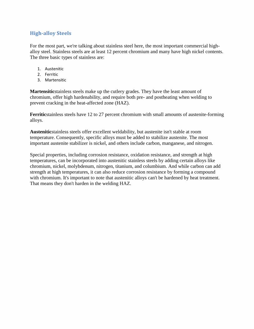
High-alloy Steels
For the most part, we're talking about stainless steel here, the most important commercial high-
alloy steel. Stainless steels are at least 12 percent chromium and many have high nickel contents.
The three basic types of stainless are:
1. Austenitic 2. Ferritic 3. Martensitic
Martensiticstainless steels make up the cutlery grades. They have the least amount of
chromium, offer high hardenability, and require both pre- and postheating when welding to
prevent cracking in the heat-affected zone (HAZ).
Ferriticstainless steels have 12 to 27 percent chromium with small amounts of austenite-forming
alloys.
Austeniticstainless steels offer excellent weldability, but austenite isn't stable at room
temperature. Consequently, specific alloys must be added to stabilize austenite. The most
important austenite stabilizer is nickel, and others include carbon, manganese, and nitrogen.
Special properties, including corrosion resistance, oxidation resistance, and strength at high
temperatures, can be incorporated into austenitic stainless steels by adding certain alloys like
chromium, nickel, molybdenum, nitrogen, titanium, and columbium. And while carbon can add
strength at high temperatures, it can also reduce corrosion resistance by forming a compound
with chromium. It's important to note that austenitic alloys can't be hardened by heat treatment.
That means they don't harden in the welding HAZ.
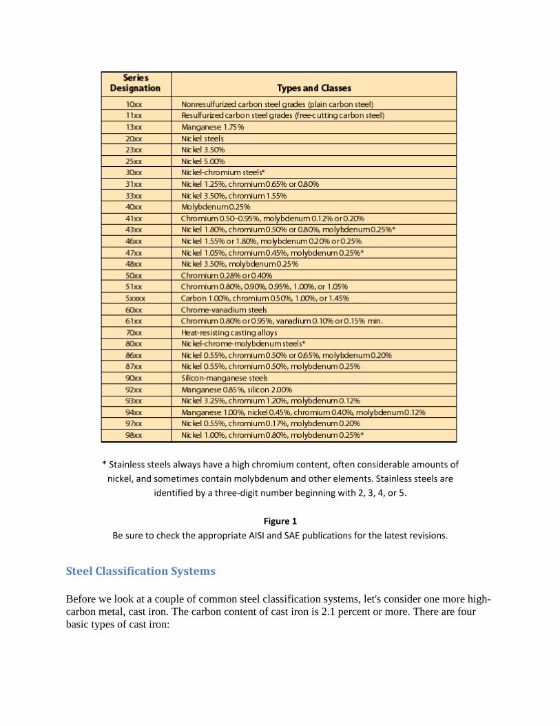
* Stainless steels always have a high chromium content, often considerable amounts of
nickel, and sometimes contain molybdenum and other elements. Stainless steels are
identified by a three-digit number beginning with 2, 3, 4, or 5.
Figure 1
Be sure to check the appropriate AISI and SAE publications for the latest revisions.
Steel Classification Systems
Before we look at a couple of common steel classification systems, let's consider one more high-
carbon metal, cast iron. The carbon content of cast iron is 2.1 percent or more. There are four
basic types of cast iron:
1. Gray cast iron, which is relatively soft. It's easily machined and welded, and you'll find it used for engine cylinder blocks, pipe, and machine tool structures.
2. White cast iron, which is hard, brittle, and not weldable. It has a compressive strength of more than 200,000 pounds per square inch (PSI), and when it's annealed, it becomes malleable cast iron.
3. Malleable cast iron, which is annealed white cast iron. It can be welded, machined, is ductile, and offers good strength and shock resistance.
4. Ductile cast iron, which is sometimes called nodular or spheroidal graphite cast iron. It gets this name because its carbon is in the shape of small spheres, not flakes. This makes it both ductile and malleable. It's also weldable.
Now let's take a look at a typical steel classification system (see Figure 1). Both the Society of
Automotive Engineers (SAE) and the American Iron and Steel Institute (AISI) use virtually
identical systems. Both are based on a four-digit system with the first number usually indicating
the basic type of steel and the first two numbers together indicating the series within the basic
alloy group.
Keep in mind there may be a number of series within a basic alloy group, depending on the
amount of the principal alloying elements. The last two or three numbers refer to the
approximate permissible range of carbon content in points (hundredths of a percent).
These classification systems can become fairly complex, and Figure 1 is just a basic
representation. Be sure to reference the most recent AISI and SAE publications for the latest
revisions.
That's a look at some basics concerning the iron-carbon-steel relationship and its influences on
welding and metal alloys. Next time we'll look at hardening and ways to make metals stronger.
We'll also consider the influences of some key alloying elements and the effects of welding on
metallurgy.