Embed Size (px)
Citation preview

PRF 368 ValveInstallation and Operation Manual
4001548 Rev A OC11
TABLE OF CONTENTSMANUAL OVERVIEW ............................................................1SAFETY INFORMATION ........................................................1TYPICAL TOOLS AND FITTINGS REQUIRED ......................2VALVE DIMENSIONS- 368 ....................................................2VALVE LAYOUT - 368 ............................................................2SPECIFICATIONS ..................................................................3EQUIPMENT INSTALLATION ................................................4CONTROL OPERATION & LAYOUT ......................................10PROGRAMMING - 368/604 ...................................................10PROGRAMMING - 368/606 ...................................................11MANUAL REGENERATION ...................................................11QUICK CYCLING THE CONTROL .........................................12SYSTEM SELECTION AND RESET PROCEDURES ............12ACCESSING HISTORY VALUES ...........................................12START-UP ..............................................................................13INSTALLATION CHECKLIST .................................................13VALVE ASSEMBLY - 368 .......................................................14TROUBLESHOOTING ...........................................................16SERVICE ASSEMBLIES ........................................................17
MANUAL OVERVIEWHow To Use This ManualThis installation manual is designed to guide the installer through the process of installing and starting the softener.This manual is a reference and will not include every system installation situation. The person installing this equipment should have:
• Knowledge in the water softener installation• Basic plumbing skills
Icons That Appear In This ManualWARNING: Failure to follow this instruction can result in
personal injury or damage to the equipment.NOTE: This will make the process easier if followed.
InspectionInspect the unit for damage or missing parts.
SAFETY INFORMATION• Review the entire Operation Manual before installing the
water conditioning system.• Follow all applicable plumbing and electrical codes when
installing this water conditioning system.• This water conditioning system is not intended for the
treatment of water that is microbiologically unsafe or of unknown quality without adequate disinfection before or after the system.
• This water conditioning system is to be used only for potable water.
• Inspect the water conditioning system for carrier shortage or shipping damage before beginning installation.
• Use caution when installing soldered metal piping near the water conditioning system. Heat can adversely affect the plastic control valve or bypass valve system. Be sure all soldered pipes are fully cooled before attaching plastic valve to the plumbing.
• Allplasticconnectionsshouldbehandtightened.Teflon*tape may be used on connections that do not use an O-ring seal. Do not use pipe dope type sealants on the valve body. Do not use pliers or pipe wrenches.
• Minimum pipe run to water heater of three meters to prevent backup of hot water into system.
• Do not use petroleum-based lubricants, oils or hydrocarbon-based lubricants. Use only 100% silicone lubricants.
• Use only the power transformer supplied with this water conditioning system.
• The power outlet must be grounded.• Install an appropriate grounding strap across the inlet and
outlet piping of the water conditioning system to ensure that a proper ground is maintained.
• To disconnect power, unplug the AC adapter from its power source.
• Observe drain line requirements. The drain line must be a minimum of 1/2-inch diameter. Use 3/4-inch pipe if the total length of the drain line exceeds 6 meters.
• Do not support the weight of the system on the control valve connections, or plumbing.
• Do not allow this water conditioning system to freeze. Damage from freezing will void this water conditioning system’s warranty.
• Keep the media tank in the upright position. Do not turn upside down or drop. Turning the tank upside down or laying the tank on its side can cause media to enter the valve.
• Use only regenerants designed for water conditioning.*TeflonisatrademarkofE.I.duPontdeMemours

TYPICAL TOOLS AND FITTINGS REQUIRED
• Pipe Cutter• Tubing Cutter• File• Pliers• Tape Measure• Soldering Tools• Lead Free Solder• Bucket • Towel• TeflonPipeTape• Adjustable Wrench• Tube 100% Silicone Grease
VALVE DIMENSIONS- 368
8.20(208.35)
6.04(153.49)
6.04(153.49)
10.75(273.08)
3.56(90.43)
3.56(90.42)
8.75(222.25)
4.71(119.70) 3.20
(81.28)
0.16(3.99)
4.36(110.70)
4.36(110.70)
0.16(3.99)
8.75(222.25)
4.71(119.70) 3.20
(81.28)
1.21(30.69) 2.50
(63.55)1.96
(49.71)
1.68(42.67)
2.00(50.80)
4.00(101.60)
1.68(42.67)
2.00(50.80)
4.00(101.60)
1.21(30.69) 2.50
(63.55)1.96
(49.71)
Figure 1
VALVE LAYOUT - 368
Figure 2
MeterCable
OutletDrain
1/2" BSPT/NPT
InletBrine
3/8" NPT
Figure 3
2•OC11PRF368Valve
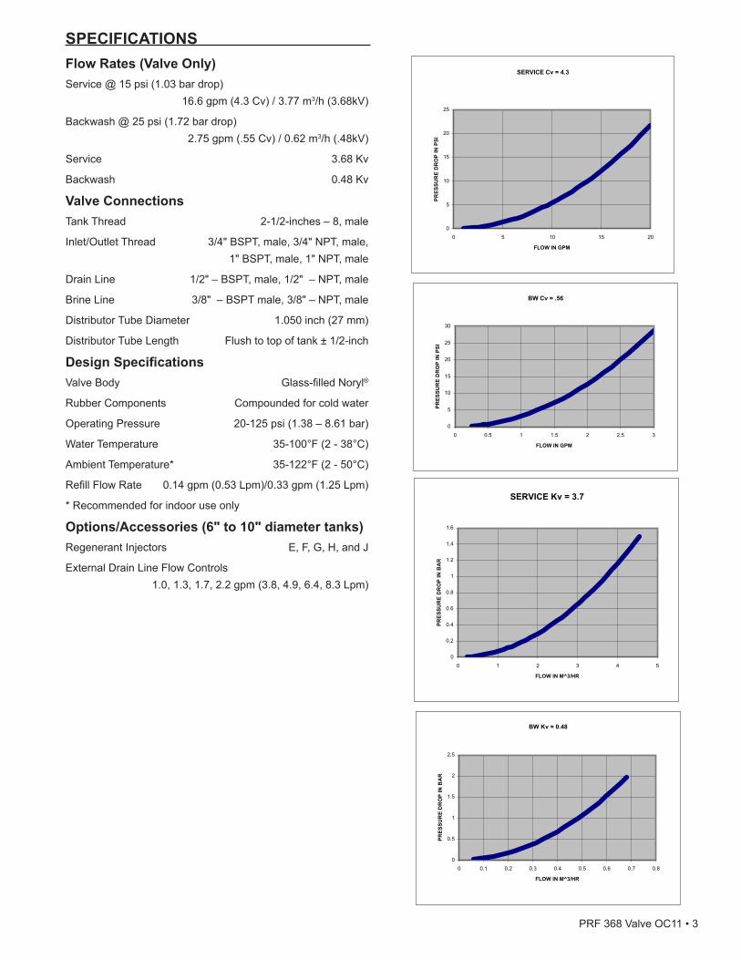
SPECIFICATIONSFlow Rates (Valve Only)Service @ 15 psi (1.03 bar drop) 16.6 gpm (4.3 Cv) / 3.77 m3/h (3.68kV)
Backwash @ 25 psi (1.72 bar drop) 2.75 gpm (.55 Cv) / 0.62 m3/h (.48kV)
Service 3.68 Kv
Backwash 0.48 Kv
Valve ConnectionsTank Thread 2-1/2-inches – 8, male
Inlet/Outlet Thread 3/4" BSPT, male, 3/4" NPT, male, 1" BSPT, male, 1" NPT, male
Drain Line 1/2" – BSPT, male, 1/2" – NPT, male
Brine Line 3/8" – BSPT male, 3/8" – NPT, male
Distributor Tube Diameter 1.050 inch (27 mm)
Distributor Tube Length Flush to top of tank ± 1/2-inch
Design SpecificationsValveBody Glass-filledNoryl®
Rubber Components Compounded for cold water
Operating Pressure 20-125 psi (1.38 – 8.61 bar)
Water Temperature 35-100°F (2 - 38°C)
AmbientTemperature* 35-122°F(2-50°C)
RefillFlowRate 0.14gpm(0.53Lpm)/0.33gpm(1.25Lpm)
*Recommendedforindooruseonly
Options/Accessories (6" to 10" diameter tanks)Regenerant Injectors E, F, G, H, and J
External Drain Line Flow Controls 1.0, 1.3, 1.7, 2.2 gpm (3.8, 4.9, 6.4, 8.3 Lpm)
SERVICE Cv = 4.3
0
5
10
15
20
25
0 5 10 15 20
FLOW IN GPM
PRES
SUR
E D
RO
P IN
PSI
BW Cv = .56
0
5
10
15
20
25
30
0 0.5 1 1.5 2 2.5 3
FLOW IN GPMPR
ESSU
RE
DR
OP
IN P
SI
SERVICE Kv = 3.7
0
0.2
0.4
0.6
0.8
1
1.2
1.4
1.6
0 1 2 3 4 5
FLOW IN M^3/HR
PRES
SUR
E D
RO
P IN
BA
R
BW Kv = 0.48
0
0.5
1
1.5
2
2.5
0 0.1 0.2 0.3 0.4 0.5 0.6 0.7 0.8
FLOW IN M^3/HR
PRES
SUR
E D
RO
P IN
BA
R
PRF368ValveOC11•3

• Alwaysmakemodificationstohouseplumbingfirst.Connect to valve last.
• Plastic parts and O-rings may be damaged by heat and solvents. When constructing plumbing connections allow heated parts to cool and protect parts from solvents.
System Recharge CyclesService(Downflow): Untreated water is directed down through the resin bed and up through the riser tube. The hardness ions attach themselves to the resin and are removed from the water. The water is conditioned as it passes through the resin bed.When a recharge cycle starts, the softener goes through seven cycles. During the recharge cycle the softener will allow untreated water to bypass into the building.1. Backwash1(Upflow):
Theflowofwaterisreversedbythecontrolvalveanddirected down the riser tube and up through the resin bed. During the backwash cycle, the bed is expanded and debris isflushedtothedrain.
2. BrineDraw(Downflow): The brine draw cycle takes place during the slow rinse cycle. The control directs water through the brine injector and brine is drawn from the salt tank. Brine draw is completed when the air check in the salt tank closes. SlowRinse(Downflow): The brine is directed down through the resin bed and up through the riser tube to the drain. The hardness ions are displaced by sodium ions and are sent to the drain. The resin is recharged during the brine cycle.
3. Repressurize Cycle (Hard Water Bypass Flapper Open): Thiscycleclosestheflappersforashorttimetoallowtheair and water to hydraulically balance in the valve before continuing the recharge.
4. FastRinse1(Downflow): The control directs water down through the resin bed and up through the riser tube to the drain. Any remaining brine residual is rinsed from the resin bed.
5. Backwash2(Upflow): Theflowofwaterisreversedbythecontrolvalveanddirected down the riser tube and up through the resin bed. During the backwash cycle, the bed is expanded and debris isflushedtothedrain.
6. FastRinse2(Downflow): The control directs water down through the resin bed and up through the riser tube to the drain. Any remaining brine residual is rinsed from the resin bed.
7. BrineRefill: Water is directed to the salt tank at a controlled rate, to create brine for the next recharge.
EQUIPMENT INSTALLATIONGeneral Warnings And Safety Information ElectricalThere are no user-serviceable parts in the AC adapter, motor, or controller. In the event of a failure, these should be replaced.
• All electrical connections must be completed according to local codes.
• Use only the power AC adapter that is supplied. If the AC adapter is replaced use a Class II, 12 volt, 150 mA supply.
• The power outlet must be grounded and always on.• To disconnect power, unplug the AC adapter from its
power source.• Install an appropriate grounding strap across the inlet
and outlet piping of the water system to ensure proper grounding is maintained.
Mechanical• Do not use petroleum based lubricants such as vaseline,
oils, or hydrocarbon based lubricants. Use only 100% silicone lubricants.
• Allplasticconnectionsshouldbehandtightened.Teflontape should be used on connections that do not use an O-ring seal. Do not use pliers or pipe wrenches.
• All plumbing must be completed according to local codes.• Soldering of the plumbing should be done before
connecting to the valve. Excessive heat will cause interior damage to the valve.
• Observe drain line requirements.• Do not use lead-based solder for sweat solder
connections.• The drain line must be a minimum of 1/2-inch diameter.
Use 3/4-inch pipe the pipe length is greater than 20 feet (6 m).
• Do not support the weight of the system on the control valvefittings,plumbing,orthebypass.
• It is not recommended to use sealants on the threads. UseTeflon*tapeonallthreads.
*TeflonisatrademarkofE.I.duPontdeNemours.
General• Observe all warnings that appear in this manual.• This system is not intended to be used for treating water
that is microbiologically unsafe or of unknown quality without adequate disinfection before or after the system.
• Keep the unit in the upright position. Do not turn on side, upside down, or drop. Turning the tank upside down will cause media to enter the valve.
• Operating ambient temperature is between 34°F (1°C) and 120°F (49°C).
• Operating water temperature is between 35°F (1°F) and 100°F (38°C).
• Working water pressure range is 20 to 125 psi (1.38 to 8.61 bar). In Canada the acceptable working water pressure range is 20 to 100 psi (1.38 to 6.89 bar).
• Use only salts designed for water softening. Acceptable salt type is sodium chloride pellet salt.
• Follow state and local codes for water testing. Do not use water that is micro-biologically unsafe or of unknown quality.
• Whenfillingmediatank,donotopenwatervalvecompletely. Fill tank slowly to prevent media from exiting the tank.
4•OC11PRF368Valve

To Regenerant Tank
BRINE REFILL
Cycle 7
FAST RINSE
Cycle 4BACKWASH
Cycle 5FAST RINSE
Cycle 6
SERVICE BACKWASH
Cycle 1
REPRESSURIZE
Cycle 3
From RegenerantTank
BRINE/SLOW RINSE
Cycle 2
Figure 4 Flow Patterns
Location SelectionLocation of a water treatment system is important. The following conditions are required:
• Levelplatformorfloor.• Ambient temperatures over 34°F (1°C) and below 120°F
(49°C).• Water pressure below 125 psi (8.61 bar) and above
20 psi (1.4 bar).• In Canada the water pressure must be below 100 psi
(6.89 bar).• Constant electrical supply to operate the controller.• Total minimum pipe run to water heater of ten feet (three
meters) to prevent backup of hot water into system.• Local drain or tub for discharge as close as possible.• Water line connections with shutoff or bypass valves.• Must meet any local and state codes for site of
installation.• Valve is designed for minor plumbing misalignments. Do
not support weight of system on the plumbing.• Be sure all soldered pipes are fully cooled before
attaching plastic valve to the plumbing.• Room to access equipment for maintenance and adding
salt to tank.
EQUIPMENT INSTALLATION continued8.75 in
(22.2 cm)4 in
(10.1 cm)
Figure 5
Outdoor LocationsIt is recommended that the equipment be installed indoors. When the water conditioning system must be installed outdoors, several items must be considered.
• Moisture — The valve and controller are rated for NEMA 3 locations. Falling water should not affect performance. The system is not designed to withstand extreme humidity or water spray from below. Examples are: constant heavy mist, near corrosive environment, upwards spray from sprinkler.
• Direct Sunlight — The materials used will fade or discolor over time in direct sunlight. The integrity of the materials will not degrade to cause system failures.
• Temperature — Extreme hot or cold temperatures may cause damage to the valve or controller. Freezing temperatures will freeze the water in the valve. This will cause physical damage to the internal parts as well as the plumbing.
• Insects — The controller and valve have been designed to keep all but the smallest insects out of the critical areas.
Things You Need to Know• Whenthecontrollerisfirstpluggedin,itmaydisplay
an Err 3, this means that the controller is rotating the camshaft to the home position.
• The preset default time of recharge is 2:00 AM.• Make sure control power source is plugged in. The
transformer should be connected to a non-switched power source.
• Test your water. Take a 4-5 oz sample of your water to someone who can test for hardness. This information will be used to setup the control.
PRF368ValveOC11•5

EQUIPMENT INSTALLATION continued
Soft Water
Hard Water
OutsideFaucet
OutsideFaucet
Bath Tub Lavatory Toilet Kitchen
Laundry TubsPump or
Meter
Hot Water Outlet
Water Heater
Brine Tank Over�ow Drain
Floor Drain
Drain Line
Bypass
Softener
GroundingStrap
Figure 6 Softened Water Flow
6•OC11PRF368Valve

EQUIPMENT INSTALLATION continuedGrounding the PlumbingIt is important that the plumbing system be electrically grounded. When a water softener is installed a nonmetallic bypass valve may interrupt the grounding. To maintain continuity, a grounding strap can be purchased at a hardware store. When it is installed the strap will connect the plumbing into the softener to the plumbing out of the softener.If you have other water treating equipment such as; chlorinator, sedimentfilter,neutralizer,ironfilter,ortaste&odorfiltertheyshould be installed upstream of the water softener.You may wish to consult a water professional if additional water treating equipment is to be installed.
Valve LayoutOutlet Inlet
Meter Cable
Drain 1/2" Tube
To Brine Tank 3/8" NPT
3/8" Tube
Figure 7
Drain Line Flow ControlThedrainlineflowcontrol(DLFC)requiresassembly (Figure 8).1. LocatepartsandarollofTeflontape.Theplumbing
adapters should be removed (Figure 10 Connector Assembly).
2. Wrapthetapeoverthreadsoftheflowcontrol.3. Screwtheflowcontrolandthe90°elbowtogether.Hand
tighten.4. Placetheballintotheflowcontrolandinserttheassembly
into the drain line opening.5. Push the assembly in and secure with the drain line clip.
90° Elbow Flow Control
Control Ball
Drain Line Clip
Figure 8
Water Line ConnectionOnce you have selected your location check the direction of thewaterflowinthemainpipe.Inspect the main water pipe. Write down the type of pipe (copper, plastic, galvanized etc.). Record the size of the pipe. Plastic style pipes usually have the size printed on the outside. Other pipes can be measured for the outside diameter and converted into the pipe size at the store. Do not use pipe that is smaller than the main water pipe. If the main plumbing is galvanized pipe and you are installing copper pipe, then you must use dielectric insulating connectors between the two styles of pipe.
WARNING: If pipes will be sweat soldered, do not connect adapters to the bypass until the pipes have cooled.
IN OUT
IN OUT
Connector Assembly
“H” Clip
Drain Line
Handles in Service Handles in Bypass
Figure 9 Bypass OperationIMPORTANT: When the valve is in bypass, water will not enter the softening tank. The water in the building will not be treated. Figure 9 Bypass Operation, shows the handles in the service position.
WARNING: The inlet water must be connected to the inlet port of the valve. When replacing a water valve, it is possible that the inlet and outlet plumbing is installed in a reversed position. Be certain the inlet connection on the valve is connected to the incoming water fitting from the water supply. Do not solder pipes with lead-based solder.
WARNING: Do not use petroleum grease on gaskets when connecting bypass plumbing. Use only 100% silicone grease products when installing any plastic valve. Non-silicone grease may cause plastic components to fail over time.
PRF368ValveOC11•7

The bypass assembly connects to the water system by means of a connector assembly. The connector is secured to the plumbing and then inserted into the bypass. A clip is used to hold it in place.
Figure 10 Connector AssemblyBefore inserting the connector:
• Check that all O-rings are in place and not damaged.• O-rings are pre-lubricated. Sliding surfaces should be
lubricated with 100% silicone grease.Firmly insert connector into bypass. Press locking clip into position. Make certain the clip is fully engaged.NOTE: Before turning on the water to the valve, rotate the
two handles on the bypass valve 2-3 times. This will help seat O-rings and prevent leaking.
To remove a clip:1. Turn off water and release water pressure at the valve.2. Push the water line connectors into the bypass and valve.
This will help release O-rings that may have seated in place.
3. Removetheclipbyinsertingaflatbladeunderthetop center of the clip and lifting (prying up) (Figure 10 Connector Assembly).WARNING: Do not use pliers to remove a clip. It is likely
the clip will break.
Drain Line ConnectionNOTE: Standard commercial practices are expressed here.
Local codes may require changes to the following suggestions. Check with local authorities before installing a system.
1. The unit should be above and not more than 20 feet (6.1 m) fromthedrain.Useanappropriateadapterfittingtoconnect1/2-inch (1.3 cm) plastic tubing to the drain line connection of the control valve.
2. If the unit is located 20-40 feet (6.1-12.2 m) from drain, use 3/4-inch(1.9cm)tubing.Useappropriatefittingstoconnectthe 3/4-inch tubing to the 3/4-inch NPT drain connection on valve.
3. The drain line may be elevated up to 6 feet (1.8 m) providing the run does not exceed 15 feet (4.6 m) and water pressure at the softener is not less than 40 psi (2.76 bar). Elevation can increase by 2 feet (61 cm) for each additional 10 psi (.69 bar) of water pressure at the drain connector.
4. Where the drain line is elevated but empties into a drain below the level of the control valve, form a 7-inch (18-cm) loop at the far end of the line so that the bottom of the loop is level with the drain line connection. This will provide an adequate siphon trap. Where the drain empties into an overhead sewer line, a sink-type trap must be used.
NOTE: The drain line connects to the elbow previously installed. It is located between the water line connections at the rear of the valve.
5. Use pliers to expand a clamp. Slide the clamp up one end of the longer length drain line tubing about 1-2 inches and release.
6. Pushthetubingovertheribbeddrainlinefitting.7. Expand the clamp and move it up the tube to pinch the tube
tothefitting.8. Secure the discharge end of the drain line to prevent it from
moving.
Right Way
Figure 11 Drain Line ConnectionNOTE: Waste connections or drain outlet shall be
designed and constructed to provide for connection to the sanitary waste system through an air-gap of 2 pipe diameters or 1 inch (22 mm) whichever is larger.
WARNING: Never insert drain line directly into a drain, sewer line, or trap (Figure 11 Drain Line Connection). Always allow an air gap between the drain line and the wastewater to prevent the possibility of sewage being back-siphoned into the softener.
EQUIPMENT INSTALLATION continued
8•OC11PRF368Valve

EQUIPMENT INSTALLATION continuedOverflow Line ConnectionIn the event of a malfunction, the salt TANK OVERFLOW will direct“overflow”tothedraininsteadofspillingonthefloor.Thisfittingshouldbeonthesideofthecabinet.Toconnecttheoverflowline,locatethetubingconnectorontheside of the tank (Figure 12 Tubing Connections). Attach length of1/2-inch(1.3-cm)I.D.tubingtofittingandruntodrain.Donotelevateoverflowlinehigherthanoverflowfitting.Donottieintodrainlineofcontrolunit.Overflowlinemustbeadirect,separatelinefromoverflowfittingtodrain,sewerortub.Allow an air gap as per drain line instructions.
OverflowConnection Salt Line Opening
Figure 12 Tubing Connections
Salt Line ConnectionThe salt line from the brine tube connects to the valve. Make certain the connections are hand tightened. Be sure that the salt line is secure and free from air leaks. Even a small leak may cause the salt line to drain out, and the softener will not draw salt from the tank. This may also introduce air into the valve causing problems with valve operation.To install the brine line:1. Inside the salt tank, remove the cap from the large cylinder
to gain access to the connection.2. Be sure the brass insert is in the end of the brine tubing.
Insert the tubing through the opening in the tank.3. Push the tubing into the plastic nut. Slowly unscrew the nut
until the tubing moves into the connection. The tubing will hit bottom.
NOTE: Once the tubing has been pushed into the nut it cannot be pulled out. The nut will need to be removed. See Figure 13 for correct assembly.
4. Hand tighten the nut until the connection is tight.
Figure 13
Electrical ConnectionWARNING: This valve and control are for dry location
use only unless used with a Listed Class 2 power supply suitable for outdoor use.
The controller operates on 12-volt alternating current power supply. This requires use of the an AC adapter with your system.Make sure power source matches the rating printed on the AC adapter. NOTE: The power source should be constant. Be certain
the AC adapter is not on a switched outlet. Power interruptions longer than 8 hours may cause the controller to lose the time setting. When power is restored, the time setting must then be re-entered.
PRF368ValveOC11•9

CONTROL OPERATION & LAYOUTLarge LED Display A large 2 digit LED readout is highly visible in most installations.
Simplified Three-Step Programming Only three buttons are required to fully program the control.
Camshaft Indicator A column of windows located on the left of the control provides a visual indicator of the camshaft rotation.
Manual Regen Button The Manual Regen button when pressed initiates either a delayed regeneration or immediate regeneration.
Time Button When pressed will display the current hour of day for 5 seconds. Press again to increase the hour of day by 1. Press and hold to change rapidly.
Salt Button Press to display the current setting (HE/HC) for 5 seconds. Press again during the 5 seconds to change the setting.
Hardness Button Press to display the hardness setting for 5 seconds. Press again during the 5 seconds to increase the setting by 1 grain per gallon. Press and hold to change rapidly.
Flow IndicatorThedecimalpoint/flowindicatorblinksonandoffwhenwaterflowturnsthemeter.
Power Loss Memory Retention The control features battery-free Time of Day retention during loss of power. The Time will remain in memory. NOTE: All other programmed parameters are stored in
the flash memory and are retained during power outages. Flash memory retention is 100 years
Refill Control Cap
Injector Cap
Camshaft Indicator
Regen Button
Display
Time Button
Salt Button
Regen Interval/Days
Button
Remove Cover
Delayed Regen Indicator
Flow Indicator
Figure 14
PROGRAMMING - 368/604
Figure 15 Time of Day: Press until desired hour appears. Release.Range: 0 through 23 hoursNOTE: The elapsed minutes will reset to zero when the
hours are changed.
Figure 16 Regenerant Dosage: Press until desired regenerant dosage appears. Release.Range: 0.5 lbs to 30 lbs0.5 lbs to 5.0 lbs by increments of 0.5 lbs (10 increments)6.0 lbs to 30 lbs by increments of 1.0 lbs (25 increments)Default: 3.0 lbsRange: 0.20 kg to 6.0 kg0.20 kg to 1.0 kg by increments of 0.05 kg1.0 kg to 3.0 kg by increments of 0.1 kg3.0 kg to 60 kg by increments of 0.5 kgDefault: 0.6 kg
Figure 17 Regen Interval: Press until desired interval appears. Release.Range: 0 through 300 = Disabled0.3 = Regeneration every 8 hours: at 2, 10 and 18 hrs0.5 = Regeneration every 12 hours: at 2 and 14 hrs1-30 = Days: 2
Programming is complete.10•OC11PRF368Valve

PROGRAMMING - 368/606
Figure 18 Time of Day: Press until desired hour appears. Release.Range: 0 through 23 hoursNOTE: The elapsed minutes will reset to zero when the
hours are changed.
Figure 19 Regenerant Dosage: Press until desired regenerant dosage appears. Release.Range: 0.5 lbs to 30 lbs0.5 lbs to 5.0 lbs by increments of 0.5 lbs (10 increments)6.0 lbs to 30 lbs by increments of 1.0 lbs (25 increments)Default: 30 lbsRange: 0.20 kg to 6.0 kg0.20 kg to 1.0 kg by increments of 0.05 kg (16 increments)1.0 kg to 3.0 kg by increments of 0.1 kg (20 increments)3.0 kg to 60 kg by increments of 0.5 kg (6 increments)Default: 0.6 kg
Figure 20 Regen Interval: Press until desired interval appears. Release. 1 (x100 gallon) to 40 (x100 gallon) by increments of 1 (x100 gallon) (40 steps)Default: 10 (x100 gallon)
Range: 0.40 to 9.5 cubic meters0.4 m3 to 1.0 m3 by increments of 0.05 m3 (12 increments)1.0 m3 to 3.0 m3 by increments of 0.1 m3 (20 increments)3.0 m3 to 5.0 m3 by increments of 0.2 m3 (10 increments)5.0 m3 to 9.5 m3 by increments of 0.05 m3 (10 increments)
Programming is complete.
Calendar Override SettingThe model 606 demand control needs a method to set days between regeneration for regulatory requirements and for caseswhentheflowsensorhasfailed.Enter by holding and for 3 seconds. The programmed calendar override is displayed. Press to increase value. Values the same as 604. 0 = no calendar override0.3 = Regeneration every 8 hours0.5 = Regeneration every 12 hours1-30 days between regenerationDefault: 0
MANUAL REGENERATIONDelayed RegenerationPress and release to program a delayed regeneration. The system will regenerate at the next Time of Regeneration (2:00 AM). Repeat procedure to disable the Delayed Regen. Regen dot blinks when delayed regeneration is on.
Immediate RegenerationPress and hold the for 3 seconds to initiate an immediate regeneration. The control cycles to backwash. The control will proceed through a complete regeneration. A cascading symbol (- -) will be displayed until regeneration is complete. The symbol (- -) is not displayed during a quick cycling of the control.
Figure 21
PRF368ValveOC11•11

QUICK CYCLING THE CONTROLQuick CyclingPress and hold the for 3 seconds to initiate an immediate regeneration. The control will cycle to the backwash cycle.1. Press and release the to display "C 1" 2. Simultaneously press then release and to move the
control to the next cycle.NOTE: The time may be displayed for 5 seconds.3. Press and release the to display "- -" or the "C#".
Continued pressing of will switch the display between "- -" and "C#".
4. Repeat steps 2 and 3 to cycle through each position.
Quick Cycle to Service Position Simultaneously press and and hold for 3 seconds during any regeneration cycle. The control will skip the remaining regeneration cycles and return to the service position. The Time of Day will be displayed when the control reaches the service position.
Figure 22
SYSTEM SELECTION AND RESET PROCEDURESThe 604 and 606 controls have four system settings available. The system selections accommodate multiple tank sizes and various feedwater water conditions. Please contact your installer before changing system settings.
System Selection:1. Press and hold the and buttons simultaneously for
3 seconds.2. A small "u" will be displayed in the left digit. The right digit
will display the current system setting.3. Press the button to scroll through the system settings.
Release the button when the desired system setting is displayed.
4. The displayed system setting will be stored in Flash memory when the control exits programming after 5 seconds.
System Selection Reset:All programmed settings with the exception of Time of Day can bereset.Enteringthevalue"0"willresettheflashmemorytothe factory default.1. Press and hold the and buttons simultaneously for
3 seconds.2. A small "u" will be displayed in the left digit. The right digit
will display the current system setting.3. Press the button and scroll the display to the "u 0"
display.
4. Wait5secondsforthesettingtobestoredintoflashmemory. The display will revert to the Time of Day setting. The control has now defaulted to System 1 setting.
5. Follow steps 1-4 of the System Selection procedure to select the desired system setting.
Programmed SettingsC# Cycle Resin
Bed Flow Direction
System u1 (min)
System u2 (min)
System u3 (min)
System u4 (min)
C1 Backwash ↑ 8 8 1 3
C2 Brine Draw ↓ Calculated Calculated Calculated Calculated
Slow Rinse 25 45 25 45
C3 Repressurize None 3 3 3 3
C4 Fast Rinse ↓ 3 3 1 3
C5 2nd Backwash
↑ 1 1 1 1
C6 2nd Fast Rinse
↓ 1 1 1 1
C7 BrineRefill None Calculated Calculated Calculated Calculated
ACCESSING HISTORY VALUESThe control features a review level that displays the operation history of the system. This is a great troubleshooting tool for the control valve.To access history values, press Recharge followed by the Salt Amount button and hold for 3 seconds to view the Diagnostic Codes.NOTE: If a button is not pushed for 30 seconds the
controller will exit the history table.Press the Time of Day button to increment through the table. When the desired code is reached, Press the Salt Amount button to display the value.Some of the values have four digits 1, 2, 3, 4. Press the Salt Amount button todisplaythefirsttwo(1,2).PresstheWater Hardness button to display the last two (3, 4). When the Salt Amount button is pressed to view H2 the currentflowratewillbedisplayedbutnotupdated.Continuetopress and release the Salt Amount button every 5 seconds toupdatethedisplay.Theflowdotonthedisplaywillflashwhenthereisflowthruthesoftener.
Code Description NotesH1 Days since last recharge Days since last recharge
H2 Currentflowrate Gallons per minute
H3 Current day of week Current day of week
H4 Water used today since 0200
In gallons, max value displayed 9999 max value stored 65,535.
H5 Water used since last recharge
A0 Average water usage for day 0
A1 Average water usage for day 1
A2 Average water usage for day 2
A3 Average water usage for day 3
A4 Average water usage for day 4
A5 Average water usage for day 5
A6 Average water usage for day 6
12•OC11PRF368Valve

START-UPThe conditioner will now need to be placed into operation. Please review Quick Cycling the Control procedure before attempting start-up.DO NOT put regenerant material into the brine tank.1. With the supply water for the system still turned off, position
thebypassvalvetothe“notinbypass”(normaloperation)position.
Both valve handles pointing
in direction of water flow
2. Press and hold the button on the controller for 3 seconds. This will initiate a manual regeneration, and cycle to the backwash position.
3. Filling the media tank with water.A. With the conditioner in backwash, open the water
supply valve very slowly to approximately the 1/4 open position. Water will begin to enter the media tank. Air willbegintobepurgedtodrainasthemediatankfillswith water.
WARNING: If opened too rapidly or too far, media may be lost out of the tank into the valve or the plumbing. In the 1/4 open position, you should hear air slowly escaping from the valve drain line.
B. When all of the air has been purged from the media tank(waterbeginstoflowsteadilyfromthedrainline),open the main supply valve all of the way. This will purgethefinalairfromthetank.
C. Allow water to run to drain until the water runs clear from the drain line. This purges any debris from the media bed.
D. Pour water into the brine tank. Advance to cycle 2 (Brine Draw) by pressing the and buttons at the same time. The water in the brine tank should be drawn into the valve. If the water is not receding from the tank, refer to Troubleshooting.
E. Quicklycyclethecontroltotherefillcycle(C7).Placesaltinbrinetank.Allowthiscycletofinishandthecontrol to move to service. The brine tank will have the correct amount of water.
WARNING: Ensure that the system has been properly disinfected per the water conditioning system manufacturer's recommendations.
The water conditioning system is now fully operational.The display will show the hour of the day. The decimal point at bottomcenterofthedisplaywillblinkwhenwaterisflowing.
INSTALLATION CHECKLIST___ Read the owner's/installation manual?___ Follow all safety guidelines in the manual?___ If metal pipe was used, did you restore the electrical ground?___ Securely install both drain hoses to an approved drain?___ Perform a leak test?___ Move the bypass valve to service?___ Sanitize the softener?___ Add salt pellets to the salt storage tank?___ Program the control correctly to meet your needs?___ Start a recharge?
PRF368ValveOC11•13

VALVE ASSEMBLY - 368
5
8
9
7
1
4
3
2
B
A
D
C
6
E
G
F
10
11
4
12
14•OC11PRF368Valve

Item No. QTY Part No. Description 1 ...............1 ..........................................Valve Body Assembly ...........4001890 ................Kit, Service, Valve 368-604B, 14,WD ...........4001891 ................Kit, Service, Valve 368-606B, 14,WD ...........4001892 ................Kit, Service, Valve 368-604B, 33,WD ...........4001893 ................Kit, Service, Valve 368-606B, 33,WD ...........4001494 ................Kit, Service, Valve 368-604B, 14, NA ...........4001495 ................Kit, Service, Valve 368-606B, 14, NA ...........4001896 ................Kit, Service, Valve 368-604B, 33, NA ...........4001897 ................Kit, Service, Valve 368-606B, 33, NA A .............1 ..........4001260 ................12 Volt Motor/Optical Sensor Cable
Assembly B .............1 ..........1000269 ................Injector Cap Assembly C.............1 ..........................................Injector/Screen Assemblies ...........3026445 ................E Injector 6" Tank - Yellow ...........3026446 ................F Injector 7" Tank - Peach ...........3026447 ................G Injector 8" Tank - Tan ...........3026448 ................H Injector 9" Tank - Lt Purple ...........4000880 ................J Injector 10" Tank - Lt Blue D.............1 ..........................................RefillFlowControlAssemblies ...........1000221 ................Ass'yRefillCont-0.14gpm ...........1243510 ................Ass'yRefillCont-0.33gpm
(Required with 1030502) ...........1030502 ................Ball, Brine-Backwash, 0.557"Dia.
Required with 1243510) E .............1 ..........3027837 ................Meter Cable F .............1 ..........................................Valve Controller Assembly - 368 ...........4001617 ................368/604B Control - NA 0.33 gpm ...........4001741 ................368/604B Control - World 0.33 gpm ...........4001618 ................368/606B Control - NA 0.33 gpm ...........4001742 ................368/606B Control - World 0.33 gpm ...........4001739 ................368/604 Control - NA 0.14 gpm ...........4001737 ................368/604 Control - World 0.14 gpm ...........4001740 ................368/606 Control - NA 0.14 gpm ...........4001738 ................368/606 Control - World 0.14 gpm G ............1 ..........4001889 ................Valve O-ring Kit 2 ...............1 ..........................................AC Wall Mound Adapters ...........1000812 ................Australian Wall Trans - 240V ...........1000813 ................British Wall Trans - 240 V ...........3031517 ................China Wall Trans - 240V ...........1262524 ................Europe Cord Connect Trans - 240V ...........1000814 ................Europe WallTrans - 240V ...........1000810 ................Japan Wall Trans - 100V ...........1000811 ................N. Amer Wall Trans - 120V ...........1030418 ................N. Amer WallTrans - 230V ...........3019151 ................N. Amer WallTrans - 120V E EFF ...........1235448 ................N. Amer Outdoor Trans - 120V 3 ...............1 ..........3027839 ................Meter Assembly 4 ...............1 ..........3031825 ................Kit, O-ring Manifold 5 ...............1 ..........4000886 ................368 Bypass
6 ...............1 ..........................................Kit, Bypass Connectors (2 connectors)
...........4001606 ................Kit, 3/4" BSP Connectors ...........4001605 ................Kit, 3/4" NPT Connectors ...........4000888 ................Kit, 1" NPT Connectors ...........4001604 ................Kit, 1" BSP Connectors 7 ...............1 ..........................................Kit, Drain Line Flow Control Bypass -
368 ...........4001297 ................#6 EXT DLFC - Bypass - BSP ...........4001298 ................#7 EXT DLFC - Bypass - BSP ...........4001299 ................#8 EXT DLFC - Bypass - BSP ...........4001300 ................#9 EXT DLFC - Bypass - BSP ...........4001545 ................#10 EXT DLFC - Bypass - BSP ...........4001284 ................#6 EXT DLFC - Bypass - NPT ...........4001285 ................#7 EXT DLFC - Bypass - NPT ...........4001028 ................#8 EXT DLFC - Bypass - NPT ...........4001286 ................#9 EXT DLFC - Bypass - NPT ...........4000887 ................#10 EXT DLFC - Bypass - NPT 8 ...............1 ..........4000871 ................Elbow 36X Valves, 3/8 tube x 3/8
NPT (only used with bypass) 9 ...............1 ..........4000996 ................Drainline 90° 1/2 NPT x 1/2 Hose
Barb 10 ...............1 ..........................................Manifold Assembly - 368 ...........3031927 ................3/4" BSP Adapter - Gray ...........4000968 ................3/4" NPT Manifold/Adapter ...........4000970 ................3/4" BSP Adapter - Black ...........4000969 ................3/4" NPT Adapter - Black 11 ...............1 ..........................................Kit, Drain Line Flow Control Manifold
- 368 (only used with manifold) ...........3031526 ................#6 EXT DLFC - Manifold - BSP ...........3031527 ................#7 EXT DLFC - Manifold - BSP ...........3031528 ................#8 EXT DLFC - Manifold - BSP ...........3031529 ................#9 EXT DLFC - Manifold - BSP ...........4001303 ................#6 EXT DLFC - Manifold - NPT ...........4001307 ................#7 EXT DLFC - Manifold - NPT ...........4001310 ................#8 EXT DLFC - Manifold - NPT ...........4001313 ................#9 EXT DLFC - Manifold - NPT ...........4000887 ................#10 EXT DLFC Bypass, NPT 12 ............................4000390 ................Bypass Clip DLFC, 360 Valve
Item No. QTY Part No. DescriptionVALVE ASSEMBLY - 368 continued
PRF368ValveOC11•15
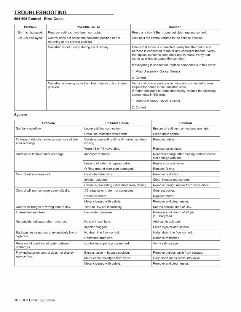
TROUBLESHOOTING604-606 Control - Error Codes
Problem Possible Cause SolutionErr 1 is displayed. Program settings have been corrupted. Press any key. If Err 1 does not clear, replace control.
Err 3 is displayed. Control does not detect the camshaft position and is returning to the service position.
Wait until the control returns to the service position.
Camshaft is not turning during Err 3 display. Check that motor is connected. Verify that the motor wire harness is connected to motor and controller module. Verify that optical sensor is connected and in place. Verify that motor gear has engaged the camshaft.
If everything is connected, replace components in this order:
1. Motor Assembly, Optical Sensor
2. Control
CamshaftisturningmorethanfiveminutestofindHomeposition:
Verify that optical sensor is in place and connected to wire. Inspect for debris in the camshaft slots. Ifmotorcontinuestorotateindefinitely,replacethefollowingcomponents in this order:
1. Motor Assembly, Optical Sensor
2. Control
System
Problem Possible Cause SolutionSalttankoverflow. Loose salt line connection. Ensure all salt line connections are tight.
Drain line restricted with debris. Clean drain control.
Flowing or dripping water at drain or salt line after recharge.
Debris is preventing #3 or #4 valve disc from closing.
Remove debris.
Worn #3 or #4 valve disc. Replace valve discs.
Hard water leakage after recharge. Improper recharge. Repeat recharge after making certain correct salt dosage was set.
Leaking of external bypass valve. Replace bypass valve.
O-Ring around riser pipe damaged. Replace O-ring.
Control will not draw salt. Restricted drain line. Remove restriction.
Injector plugged. Clean injector and screen.
Debris is preventing valve discs from closing. Remove foreign matter from valve discs.
Control will not recharge automatically. AC adapter or motor not connected. Connect power.
Defective motor. Replace motor.
Meter clogged with debris. Remove and clean meter.
Control recharges at wrong time of day. Time of Day set incorrectly. Set the correct Time of Day.
Intermittent salt draw. Low water pressure. Maintain a minimum of 20 psi (1.3 bar) feed.
No conditioned water after recharge. No salt in salt tank. Add salt to salt tank.
Injector plugged. Clean injector and screen.
Backwashes or purges at excessively low or high rate.
Nodrainlineflowcontrol. Installdrainlineflowcontrol.
Restricted drain line. Remove restriction.
Runs out of conditioned water between recharges.
Control improperly programmed. Verify salt dosage.
Flow indicator on control does not display serviceflow.
Bypass valve in bypass position. Remove bypass valve from bypass.
Meter cable dislodged from valve. Fully insert meter cable into valve.
Meter clogged with debris. Remove and clean meter.
16•OC11PRF368Valve

SERVICE ASSEMBLIESValve Body Assemblies:4001890..........................Kit, Service, Valve 368-604B, 14, World4001891..........................Kit, Service, Valve 368-606B, 14, World4001892..........................Kit, Service, Valve 368-604B, 33, World4001893..........................Kit, Service, Valve 368-606B, 33, World4001494..........................Kit, Service, Valve 368-604B, 14, N. America4001495..........................Kit, Service, Valve 368-606B, 14, N. America4001896..........................Kit, Service, Valve 368-604B, 33, N. America4001897..........................Kit, Service, Valve 368-606B, 33, N. America4001889..........................Valve O-ring Kit
Controllers:4001617.......................... 368/604B Control - North America 0.33 gpm4001618.......................... 368/606B Control - North America 0.33 gpm4001739.......................... 368/604 Control - North America 0.14 gpm4001740.......................... 368/606 Control - North America 0.14 gpm4001741.......................... 368/604B Control - World 0.33 gpm4001742.......................... 368/606B Control - World 0.33 gpm4001737.......................... 368/604 Control - World 0.14 gpm4001738.......................... 368/606 Control - World 0.14 gpm
Motors:4001260.......................... 12 Volt Motor/Optical Sensor/Cable Assembly
Injectors:1000269.......................... Injector, Cap Assembly3026445..........................E Injector 6" Tank - Yellow3026446..........................F Injector 7" Tank - Peach3026447..........................G Injector 8" Tank - Tan3026448..........................H Injector 9" Tank - Lt Purple4000880.......................... J Injector 10" Tank - Lt Blue1000221..........................Ass'yRefillCont-0.14gpm(Required
with 1030502)1030502..........................Ass'yRefillCont-0.33gpm(Required
with 1243510)
Meters:3027837..........................Meter Cable3027839..........................Meter Assembly
Bypass/Manifold:4000886.......................... 368 Bypass3031927.......................... 3/4" BSP Adapter - Gray4000968.......................... 3/4" NPT Manifold/Adapter4000970.......................... 3/4" BSP Adapter - Black4000969.......................... 3/4" NPT Adapter - Black3031825..........................Kit, O-ring Manifold3027832..........................Bar, Locking, SS, 360 Series40576..............................Clip, H, Plastic
DLFC:4001297.......................... #6 EXT DLFC - Bypass - BSP4001298.......................... #7 EXT DLFC - Bypass - BSP4001299.......................... #8 EXT DLFC - Bypass - BSP4001300.......................... #9 EXT DLFC - Bypass - BSP4001545.......................... #10 EXT DLFC - Bypass - BSP4001284.......................... #6 EXT DLFC - Bypass - NPT4001285.......................... #7 EXT DLFC - Bypass - NPT4001028.......................... #8 EXT DLFC - Bypass - NPT4001286.......................... #9 EXT DLFC - Bypass - NPT4001287.......................... #10 EXT DLFC - Bypass - NPT3031526.......................... #6 EXT DLFC - Manifold - BSP3031527.......................... #7 EXT DLFC - Manifold - BSP3031528.......................... #8 EXT DLFC - Manifold - BSP3031529.......................... #9 EXT DLFC - Manifold - BSP4001303.......................... #6 EXT DLFC - Manifold - NPT4001307.......................... #7 EXT DLFC - Manifold - NPT4001310.......................... #8 EXT DLFC - Manifold - NPT4001313.......................... #9 EXT DLFC - Manifold - NPT4000887.......................... #10 EXT DLFC - Bypass - NPT4000390..........................Bypass Clip, DLFC, 360 Valve
Fittings/Connectors:4000871..........................Elbow 36X Valves, 3/8 Tube x 3/8 NPT (Only
used w/Bypass)4000996..........................Drainline 90°, 1/2 NPT x 1/2 Hose Barb4001606..........................Kit, 3/4" BSP Connectors4001605..........................Kit, 3/4" NPT Connectors4000888..........................Kit, 1" NPT Connectors4001604..........................Kit, 1" BSP Connectors
Power:1000812..........................Australian Wall Trans - 240V1000813..........................British Wall Trans - 240V3031517..........................China Wall Trans - 240V1262524..........................Europe Cord Connect Trans 240V1000814..........................Europe Wall Trans - 240V1000810.......................... Japan Wall Trans - 100V1000811 ..........................N. Amer Wall Trans - 120V1030418..........................N. Amer Wall Trans - 230V3019151..........................N. Amer Wall Trans - 120V E EFF1235448..........................N. Amer Outdoor Trans - 120V
PRF368ValveOC11•17

18•OC11PRF368Valve

PRF368ValveOC11•19

©2011 Pentair Residential Filtration, LLC 4001548 Rev A OC11