Embed Size (px)
Citation preview

2017
Preventative Maintenance Service Manual


Date
Tub Model
Serial #
155 Norcom Way • Sparta, TN 38583
Facility Name Phone Contact
Address City State Zip
Pre-In-service Installation Inspection
1. Inspect tub for any damage that has occurred during shipping or installation.
2. Make sure all hoses and drain lines have been tightened.
3. Operate door to make sure it is working properly. Is Delrin on bottom of locking assembly tight?
4. Check shower and disinfectant wand to hose, make sure they are tightly attached.
5. Turn valve to disinfect- check for leaks. Turn to rinse, check for leaks. Turn to off.
6. Turn Thermostatic Mixing Valve to maximum setting, turn on tub fill - Should read 104°F or 40°C
7. Turn on shower wand and check for leaks. Should read 104°F or 40°C
8. Fill the tub, and check for door leaks; operate the air spa system.
9. Have you made all the necessary adjustments and are satisfied with this product.
Notes:
In-service Training
1. Proper opening, closing and locking of door.
2. Proper operating of the valve system, tub fill, shower wand, temperature read out.
3. Fill the tub up to the over flow.
4. Operate the key pad and air spa ( explain air system will automatically come on after 10 min cycle )
5. Drain the tub and show them how to load disinfectant and use the system.
6. Questions and answers
Faculty and RANE Representative Sign Off 1. Questions and concerns were addressed fully during the course of today's in-service.
2. I now have the proper knowledge to operate and service our tub.
3. I am happy with the quality and performance of my tub.
No. Staff Available for Training D.O.N. Administrator
Name Title
RANE In-Service Representative Date of In-Service


TABLE OF CONTENTS
PREVENTATIVE MAINTENANCE CHECKLIST 2
SERVICE ITEMS DOORS
Adjustment 3 Adjustment (RR7) 4 Tension Adjustment (RR7) 5
Handle Adjustment 6 Seal Replacement 7
Seal Replacement (RR7) 8 AIR SPA CleanRaneTM Air Spa 9 Button Functions 10 Check Motor Mounts 11 Check Blower Hose Clamps 12 Motor Replacement 13 Motor Replacement (RR7) 14 Jet Replacement 15 FAQs 16 SCHMIEDL VALVE Service Bulletin (1/2” and 3/4” Schmiedl Valves) 18 Schmiedl Valves Replacement 19 THERMOSTATIC MIXING VALVE Calibration 22 Handle Assembly 23 Cartridge Removal 24 DISINFECTANT Checking DEMA Valve Function 25
Cleaning a DEMA Valve 26 Check Valve Replacement 27 ACTUATOR Check Actuator Mount 28 Replacement (RR7 ) 29
Replacement (RS8) 31 DRAIN Cable Drain Correction / Adjustment 32 Drain Stop Repair 33
TROUBLESHOOTING MATRIX 34
UPGRADES BUTTONS RR7 Recline Button Replacement 37
RR7 Autofill Button Replacement 38 RS8 2-Button Height Adjust Replacement 39
RS8 4-Button Height Adjust Replacement 40 RS8 Autofill Button Replacement 41 THERMOMETER Thermometer Replacement 42
Thermometer Replacement (RS8) 43 DISINFECTANT WAND Upgrade Disinfectant Wand 44
RANE PARTS AND SOLUTIONS 46


Preventative Maintenance Checklist
Check and ensure that the thermostatic mixing valve is working
properly.
Check to ensure that the thermometer is providing an accurate
reading.
Disconnect the water supply hoses, and check inlet screen for
debris.
Check hinge bolts and ensure they are secured tightly.
Check gas shock on RR7II for proper tension.
Check door seal for wear or tears.
Check to ensure the DEMA valve is still diluting 59mL (2 oz) of
disinfectant per 4L (1 gal) of water.
Check and ensure the actuator operations for functionality.
(RR7II & RS8)
Check and ensure actuator mounting bolts and pins are secure.
(RR7II & RS8)
Check and ensure functionality of Air Spa blower keypad.
Check and ensure Air Spa blower bolts are secure and motor
mounts tight.
Check and ensure Air Spa blower hose (grey) clamps are secure
on the motor and manifold.
Check for corrosion around the Air Spa blower’s grey Cat5 cable.
Check and ensure the battery backup is working properly on
the RS8 (Height Adjustable) and the RR7II (If equipped).
2

ADJUST RH4, RT4, RH6, RG9, RK12 AND RB14 DOOR TOOLS NEEDED: #3 AND #2 PHILLIPS SCREWDRIVER, 5/64 ALLEN WRENCH
3
Turn set screw (which is on the bottom of the lock slide) 1 revolution clockwise. Check for
leaks. If door still leaks repeat this step.
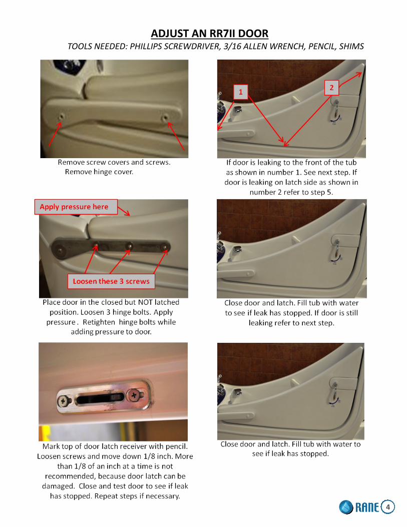
ADJUST AN RR7II DOOR TOOLS NEEDED: PHILLIPS SCREWDRIVER, 3/16 ALLEN WRENCH, PENCIL, SHIMS
4

RR7II- CHECK DOOR TENSION 1) Ensure tub is in the lowest position.
2) Open door to a position between 1 and 2 o'clock.
3) Door should stay in place.
4) If the door moves down, refer to instructions below.
RR7II- ADJUST DOOR TENSION TOOLS NEEDED: PHILLIPS SCREW DRIVER, 1/4” RATCHET DRIVE, 5/16” SOCKET
1) Ensure tub is in the lowest position.
2) Locate the front access panel.
3) Open the 4 hinged screw caps using a knife or small flat head screw driver. (See Figure 1)
4) Remove the 4 screws using a Phillips screw driver.
5) Set the panel aside. KEEP TRACK OF ALL SCREWS.
6) Slightly tighten the 4 Phillips screws on the door hinge shown below.
7) Open door to a position between 1 and 2 o'clock.
8) Repeat steps 6 and 7 until the door stays in the 1 to 2 o'clock position. The door should be easy to lift and close as well.
FIGURE 1
5
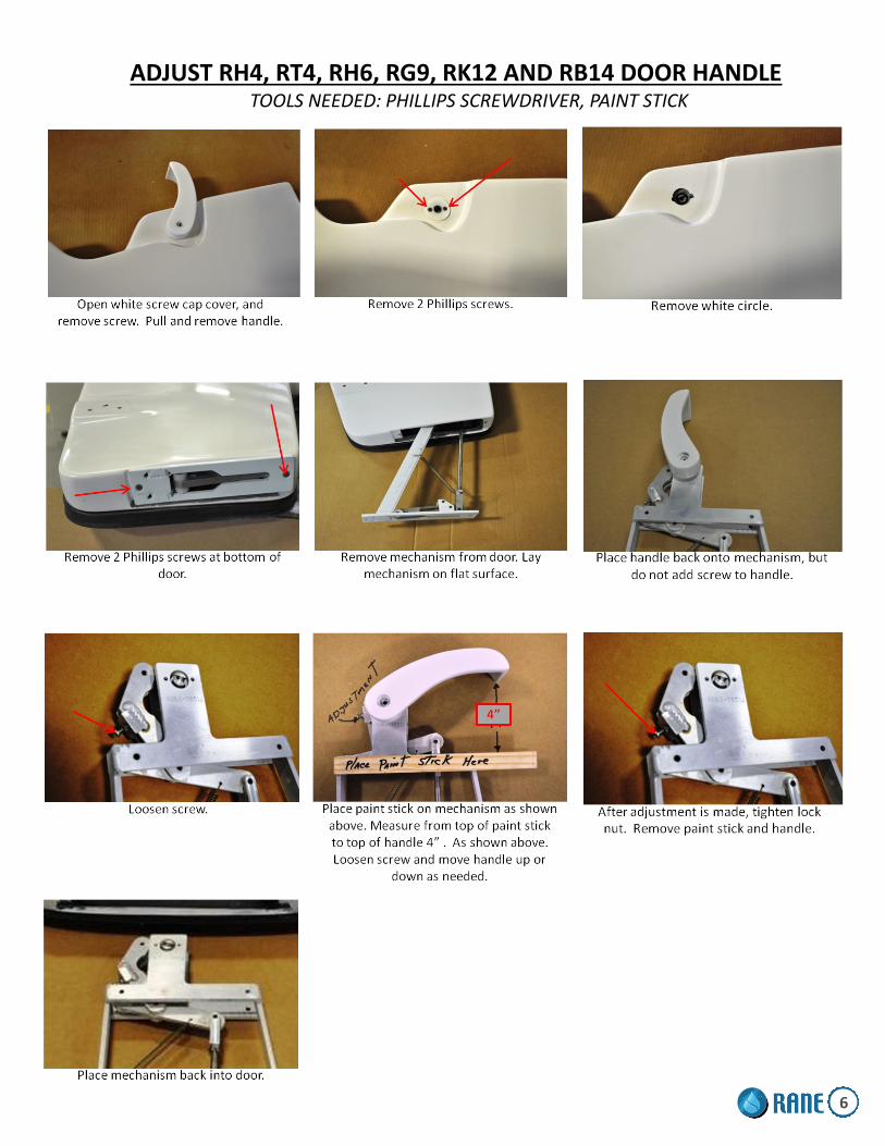
ADJUST RH4, RT4, RH6, RG9, RK12 AND RB14 DOOR HANDLE TOOLS NEEDED: PHILLIPS SCREWDRIVER, PAINT STICK
6

REPLACING A RH4, RT4, RH6, RG9, RK12 AND RB14 DOOR SEAL
7

REPLACING AN RR7 DOOR SEAL
CONTENTS OF DOOR SEAL Rubber Door Seal Two (2) Black Push Pins Contact Cement Sandpaper Brush INSTRUCTIONS 1. Using a paint brush, apply an even coat of glue to both the rough surface of seal and
surface on the door.
2. Allow the glue on both surfaces to skin over (approximately five (5) minutes).
3. Beginning at one end of the seal, carefully place the seal into seal area of door taking care to make good contact between the door and seal. Be sure that the wide flat portion of seal is positioned as shown.
CORRECT POSITIONING INCORRECT POSITIONING INCORRECT POSITIONING
4.Use masking tape as necessary to help hold seal in place. 5.When entire seal is in place, taper ends as needed for proper fit and insert push pins at both ends of doors. 6.Use lacquer thinner on a towel to clean excess glue off the door surface.
7.Allow the glue to set for at least two (2) hours before the first use.
NOTE: THE USE OF PETROLEUM BASED CLEANERS OR LUBRICANTS WILL CAUSE RUBBER DOOR SEAL TO FAIL. TO CLEAN AND MAINTAIN SEAL, USE MILD SOAP AND WATER OR PRODUCTS DESIGNED SPECIFICALLY FOR RUBBER PRODUCTS.
Wide
Narrow
8

CLEANRANETM AIR SPA
The CleanRane™ Air-Spa System features spring loaded check valves with back flow prevention, eliminating the extra step to disinfect or flush the air lines. This provides the highest level of protection from bacteria and contaminants. When the system is turned off, the spring loaded check valves shut immediately, therefore, no water or debris can enter the air-spa lines. Simply disinfect the surface of the tub and air-spa jets, which kills the bacteria and contaminants. Rinse the tub and you’re ready to go.
The CleanRane™ Air Spa System features 12 jets strategically placed for maximum effect.
9

AIR SPA BUTTON FUNCTIONS
AIR SPA BUTTON ON/OFF BUTTON • 1st press: Blower turns on at high speed
• 2nd press: Blower changes to lo speed
• 3rd press: Blower turns off
AIR SPA KEYPAD (Discontinued- may be on older models)
ON/OFF BLOWER
1st press: The blower starts 2nd press: The blower stops
BLOWER SPEED VARIATION
1st press: Press & hold to increase the blower speed, release pressure at desired speed
2nd press: Press & hold to lower the blower speed, release pressure at desired speed.
PULSATION MODES
1st press: Wave—Speed will vary gradually from maximum to minimum
2nd press: Pulse—Speed will go directly to minimum and then straight to maximum.
3rd press: Returns to maximum speed.
BLOWER SPEED
ON / OFF
PULSATION
10

CHECK AIR SPA MOTOR MOUNTS
1) Open the disinfectant door and locate the Air Spa motor. (RR7II - Remove the front panel using a knife and Phillips screw driver)
2) Ensure the 3 bolts are secure. 3) Tighten with a 1/2" wrench.
11

CHECK AIR SPA BLOWER HOSE CLAMPS
Hose clamps should be attached to air spa motor as shown.
Hose clamps should be attached to manifold as shown.
12
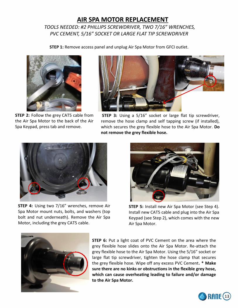
AIR SPA MOTOR REPLACEMENT TOOLS NEEDED: #2 PHILLIPS SCREWDRIVER, TWO 7/16” WRENCHES,
PVC CEMENT, 5/16” SOCKET OR LARGE FLAT TIP SCREWDRIVER
STEP 1: Remove access panel and unplug Air Spa Motor from GFCI outlet.
STEP 2: Follow the grey CAT5 cable from the Air Spa Motor to the back of the Air Spa Keypad, press tab and remove.
STEP 3: Using a 5/16” socket or large flat tip screwdriver, remove the hose clamp and self tapping screw (if installed), which secures the grey flexible hose to the Air Spa Motor. Do not remove the grey flexible hose.
STEP 4: Using two 7/16” wrenches, remove Air Spa Motor mount nuts, bolts, and washers (top bolt and nut underneath). Remove the Air Spa Motor, including the grey CAT5 cable.
STEP 5: Install new Air Spa Motor (see Step 4). Install new CAT5 cable and plug into the Air Spa Keypad (see Step 2), which comes with the new Air Spa Motor.
STEP 6: Put a light coat of PVC Cement on the area where the grey flexible hose slides onto the Air Spa Motor. Re-attach the grey flexible hose to the Air Spa Motor. Using the 5/16” socket or large flat tip screwdriver, tighten the hose clamp that secures the grey flexible hose. Wipe off any excess PVC Cement. * Make sure there are no kinks or obstructions in the flexible grey hose, which can cause overheating leading to failure and/or damage to the Air Spa Motor.
13

AIR SPA MOTOR REPLACEMENT- RR7 TOOLS NEEDED: #2 PHILLIPS SCREWDRIVER, TWO 7/16” WRENCHES,
PVC CEMENT, 5/16” SOCKET OR LARGE FLAT TIP SCREWDRIVER
Make sure all is power is off to the tub. Open white cap screw covers and use a Phillips head screwdriver to remove 4
screws. Remove the back turtle access panel. Slowly bring panel out and unplug up/down button wires. Take a flat head screwdriver and remove 4 screws on gray junction box. Loosen black connectors on junction box. Pull out the wire connectors and dis-
connect the air spa wires. Cut the old air spa motor cord right beside old motor. Attach a rubber band to the old cord and the new air spa motor cord and pull
cord thru to the other end of tub. Remove old air spa motor, by loosening up bolts on pump mount Place new air spa motor in tub and attach with bolts from old air spa motor. Cut end off of new air spa motor cord. Strip wires as needed. Attach wires in junction box with wire connectors, to correct color coding. Plug gray cord on tub in GFI outlet and test air spa motor. If motor works correctly refer to next step. If not make sure wires are hooked
up correctly and wire connectors are tight. After motor is tested and working properly, replace gray junction box cover
with 4 screws. Replace turtle shell cover on back of tub. Attach wires to the up/down buttons on tub. Replace 4 screws to white panel. Close white screw covers.
14

AIR SPA JET REPLACEMENT TOOLS NEEDED: SMALL FLAT TIP SCREWDRIVER AND SMALL NEEDLE NOSE PLIERS
STEP 1: Turn on air spa motor for 30 seconds to blow out any water in the assembly.
STEP 2: Place the drain plug over drain hole or close cable drain to avoid any parts falling into the tub drain.
STEP 3: Using a small flat tip screwdriver, insert tip into one of the 6 small openings in the jet cover cap and gently pop off. Be careful not to damage gelcoat or nylon assembly. Using small needle nose pliers, remove the “Y” piece (see Fig. 1) to expose the internal parts of the jet assembly and remove the old brass insert and spring . Do not lose or throw out the “Y” piece, set aside.
Openings
STEP 6: Insert the “Y” piece directly centered on the spring. Push down on the “Y” piece till it snaps into place. Spring must be centered to work properly (see above picture). Install jet cover cap. Press until you hear a snap noise indicating it’s in the correct position.
“Y” Piece “Y” Piece
STEP 4: Make sure the jet assembly is free of debris, mildew, or any buildup before inserting new brass insert and spring. Clean with cotton swab if needed. Insert the new brass insert and spring into the existing jet assembly. Make sure the spring is installed directly in the center of the jet assembly.
15

AIR SPA FAQ’s
Can the air blower be installed anywhere other than under the bathtub? Yes, it can. The air blower can be installed up to 15 feet away from the bathtub. However, 1. Never insulate the blower. However, it is recommended to insulate the air hose to prevent cooling of the air circulating within. 2. The ambient air surrounding the air blower must be maintained at the same temperature as the room where the bathtub is installed. The blower was not designed to heat cold air from a basement or a garage.
The blower starts on its own. Almost all air blowers are standard with a built in automatic purge cycle that will start 10 minutes after the use of the system. However, 1. If there is a power outage, the purge cycle could be activated. 2. If the system is equipped with a water detector, the purge cycle will start every time there is water in the bath-tub (after you shower, after cleaning the bathtub, etc.). 3. If this happens often even if the system has not been used, contact your dealer. The keypad could be defective and will have to be replaced.
The purge cycle does not start. First verify with your distributor to make sure that your blower is equipped with this option. If it is: 1. Verify that the power to your system does not go through a timer or a security switch. If the timer or switch was shut off before the purge cycle count down has finished, the blower will not turn on. 2. Verify that there is no water in the bottom of your bathtub. Your system may be equipped with a water detec-tor that is preventing the purge cycle to start.
Can the air blower be installed anywhere other than under the bathtub? Yes, it can. The air blower can be installed up to 15 feet away from the bathtub. However, 1. Never insulate the blower. However, it is recommended to insulate the air hose to prevent cooling of the air circulating within. 2. The ambient air surrounding the air blower must be maintained at the same temperature as the room where the bathtub is installed. The blower was not designed to heat cold air from a basement or a garage.
The blower starts on its own. Almost all air blowers are standard with a built in automatic purge cycle that will start 20 minutes after the use of the system. However, 1. If there is a power outage, the purge cycle could be activated. 2. If the system is equipped with a water detector, the purge cycle will start every time there is water in the bath-tub (after you shower, after cleaning the bathtub, etc.). 3. If this happens often even if the system has not been used, contact your dealer. The keypad could be defective and will have to be replaced.
The purge cycle does not start. First verify with your distributor to make sure that your blower is equipped with this option. If it is: 1. Verify that the power to your system does not go through a timer or a security switch. If the timer or switch was shut off before the purge cycle count down has finished, the blower will not turn on. 2. Verify that there is no water in the bottom of your bathtub. Your system may be equipped with a water detec-tor that is preventing the purge cycle to start. Unfortunately some people are more sensitive to this effect than others. The solution is to change positions in the bathtub and the sensation will diminish. 16
AIR SPA FAQ’s (Continued)
The purge cycle does not start. First verify with your distributor to make sure that your blower is equipped with this option. If it is: 1. Verify that the power to your system does not go through a timer or a security switch. If the timer or switch was shut off before the purge cycle count down has finished, the blower will not turn on. 2. Verify that there is no water in the bottom of your bathtub. Your system may be equipped with a water detec-tor that is preventing the purge cycle to start. Unfortunately some people are more sensitive to this effect than others. The solution is to change positions in the bathtub and the sensation will diminish.
The air blower functions but the options on my keypad do not always function. 1.If the problem is only with the « + » button; please note that your system starts at a maximum speed. There-fore, pressing this button will have no effect. To verify the proper function of your system press the « – » button; the speed should go down. Then press the « + » button and the speed will increase. 2. If it is a problem with any other button, your keypad could be defective. Sometimes a humidity problem can occur within the electronic system if a wet cloth is left too long on the keypad or if the keypad label is cracked. Contact your distributor who will guide you through the procedure to have your keypad changed.
I press on the air push button but the system does not turn on or off. With an air push button the solutions are quite simple most of the time. 1. If the button is hard to press or comes back too slowly to its initial position, there may be too much air accumu-lated within the hose. - To correct the problem, locate the transparent hose and with a thin pin, poke one or two holes through it to let the air out. (This will not harm your system in any way). - Verify that the hose is not kinked or bent preventing the air from flowing easily. 2. If the button is easy to manipulate, unplug the transparent hose from under the button and gently blow into it. - If the blower starts, the problem is in the air push button. - If the blower does not start, the problem is in the blower. In both cases, contact your distributor for the procedure to have the defective part replaced. Please in-form them of your testing results.
Nothing seems to work. 1. Check the main power box of the house if the breaker is at the ON position. 2. Check if the ground fault circuit interrupter (GFCI) has not tripped. Most manufactures test their products be-fore it leaves the plant. Risks that nothing works are almost null. Interrupt the current for 15 seconds and then reconnect it. This should solve your problem.
My ground fault circuit breaker switches off. 1. If your bathtub is equipped with both a whirlpool pump and an air blower, verify that each unit is connected to a separate ground fault circuit interrupter (GFCI). 2. Sometimes it can occur that the interrupter (GFCI) is too sensitive. To verify this, disconnect the blower and connect either a hair blower or a light bulb. If the ground fault circuit interrupter trips again, it may be that there is a short circuit somewhere in the electrical line. Have your electrician verify the problem. If the problem persists, the ground fault circuit should be replaced.
17
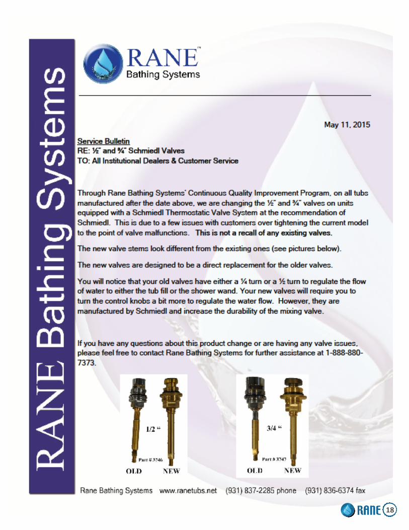
18

HOW TO REPLACE A TUB-FILL OR SHOWER DIVERTER VALVE STEM TOOLS NEEDED: CRESCENT WRENCH, SILICONE ADHESIVE, AND 17MM SOCKET (if needed)
Figure 1
Step 1: Using both hands, grip the knob firmly. Pull firmly and
steady to remove the knob.
Step 2: Remove the chrome
escutcheon and gently peel off
the rubber gasket.
Step 3: Using a crescent wrench, remove part
A (fig.1). Hold the valve assembly firmly with
your fingers.
Step 4: Remove part B (fig.1). Simply pull
straight out.
19

HOW TO REPLACE A TUB-FILL OR SHOWER DIVERTER VALVE STEM (Continued)
Step 5: Using a crescent wrench, remove part C (fig.1). Step 6: Remove part D (fig.1).
Step 7: Using a crescent
wrench, remove part E (fig.1).
Step 8: Use tongue & groove
pliers on base of valve stem and
remove.
Step 9: Insert and carefully thread
in new valve stem. Hand tighten.
Step 10: Use tongue & groove
pliers on base of valve stem
and tighten until it stops. Be
careful not to over tighten
and snap the stem.
Step 11: Re-install part E (fig.1).
Note: Do not over tighten.
Step 12: Re-install part D
(fig.1)/
Step 13: Using a crescent wrench, Re-install part C (fig.1)/ Step 14: Re-install part B (fig1).
20

HOW TO REPLACE A TUB-FILL OR SHOWER DIVERTER VALVE STEM (Continued)
Step 15: Re-install part A (fig.1). Hand tighten until it stops, then using the crescent wrench, tighten 2 full
turns. Note: Do not over tighten. If turning the valve on and off is stiff or makes a grinding noise, the nut
is too tight. Back off by loosening a 1/2 to 1 turn. The valve should be fluid and easy to turn on and off.
Step 16: Re-install the chrome escutcheon and rubber gasket. Note: If rubber gasket loses its adhesive
backing during removal in Step 2, use a small bead of silicone adhesive around the entire rubber
gasket. Wipe off any excess silicone.
Step 17: Align the teeth inside the knob with the teeth on part B (fig.1). Using the palm of your hand,
push in the knob firmly until it locks into place. Note: If knob doesn’t lock into place, use a small
amount of shampoo or body wash on the teeth for lubrication.
Note: If the valve stem is broken off, use either a 17mm socket or channel locks to remove it. Remove
all of the parts (A-E on fig.1) from the broken valve and begin at Step 9. If parts cannot be removed
from the broken valve, you’ll need to order the complete valve package (item # 1685-1/2” shower
valve or # 1690– 3/4” tub-fill valve). 21
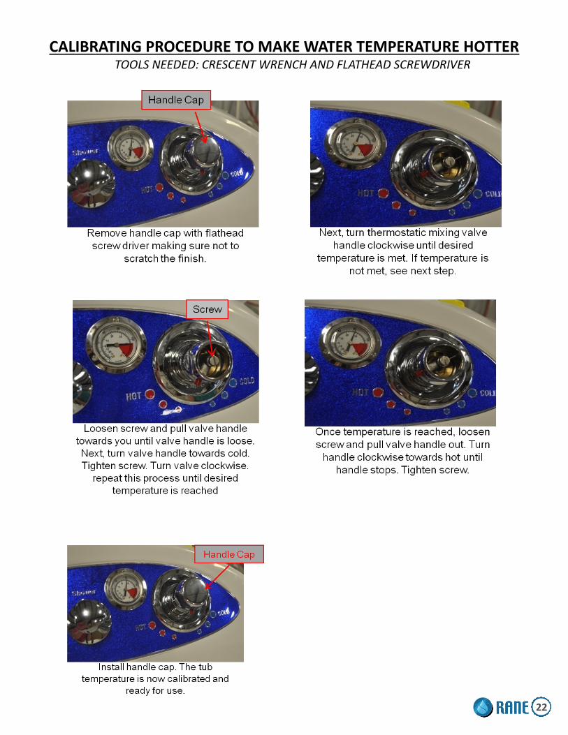
CALIBRATING PROCEDURE TO MAKE WATER TEMPERATURE HOTTER TOOLS NEEDED: CRESCENT WRENCH AND FLATHEAD SCREWDRIVER
22

THERMOSTATIC MIXING VALVE HANDLE ASSEMBLY TOOLS NEEDED FOR INSTALLATION: SMALL FLAT TIP SCREWDRIVER, LARGE FLAT TIP SCREWDRIVER
23

THERMOSTATIC MIXING VALVE CARTIDGE REMOVAL TOOLS NEEDED: SMALL FLAT TIP SCREW DRIVER, LARGE FLAT TIP SCREW DRIVER, CRESCENT WRENCH
AFTER REMOVING CARTRIDGE, SOAK IN 1 TBSP BAKING SODA PER 8 OZ WATER.
24
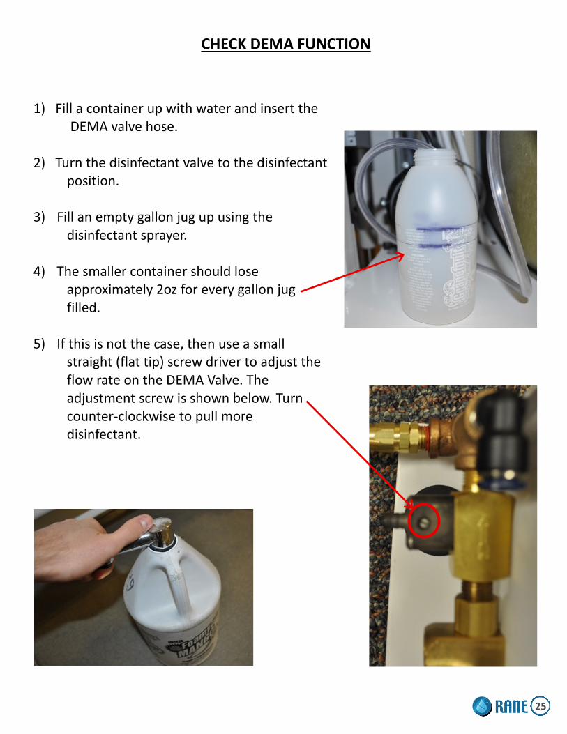
CHECK DEMA FUNCTION
1) Fill a container up with water and insert the DEMA valve hose. 2) Turn the disinfectant valve to the disinfectant position. 3) Fill an empty gallon jug up using the disinfectant sprayer. 4) The smaller container should lose approximately 2oz for every gallon jug filled. 5) If this is not the case, then use a small straight (flat tip) screw driver to adjust the flow rate on the DEMA Valve. The adjustment screw is shown below. Turn counter-clockwise to pull more disinfectant.
25

CLEANING A DEMA VALVE TOOLS NEEDED: ADJUSTABLE WRENCH, 3/32” ALLEN WRENCH, FLATHEAD SCREWDRIVER
STEP 2: Remove the knob using a 3/32” Allen
wrench. Remove the large nut holding the 3-way Valve in place with an Adjustable wrench. Simply pull or push the disinfectant valve system out of the hole, which will allow easy access for the repair/cleaning.
STEP 1: Turn cold water supply off and identify the Disinfectant Valve System, which consists of a Metering Knob Assembly and Disinfectant Injector.
STEP 3: Remove the clear hose that goes from the Metering Knob Assembly to the disinfectant bottle. Run hot water through the hose and filter on the end to remove debris or build-up.
STEP 4: Label or mark the hoses to insure they are reconnected correctly. Remove the hoses using the quick disconnects and/or compression nut (Adjustable wrench needed). * Removing the hoses is not required, however, it makes it easier to perform the task.
Metering Knob Assembly
Disinfectant Injector
26

REPLACING A CHECK VALVE
TOOLS NEEDED: ADJUSTABLE WRENCH AND TEFLON TAPE
Arrow towards Brass T
New Check Valve
Quick Connect
STEP 5: Reconnect hoses that lead to disinfection system back into quick connects as shown above. Reconnect the hose that leads to the main cold water supply. Turn on main water supply and check for leaks.
STEP 4: With teflon tape, wrap quick connect threads and screw tightly into Check Valve, then wrap Check Valve threads and screw tightly into the Brass T with arrows pointing towards Brass T. DO NOT OVER TIGHTEN.
STEP 3: Disconnect hoses that lead to the disinfection system. Remove quick connect from Check Valve. Remove Check Valve from Brass T.
STEP 2: Disconnect hose coming into the Brass T from the main cold water supply.
STEP 1: Shut off main water supply and locate the Brass T that branches off the main cold water supply and feeds the disinfection system.
Check Valve
Brass T
Hoses to Disinfection System
27

CHECK ACTUATOR MOUNT - RR7II
1) Ensure tub is in the highest position.
2) Ensure the actuator mount under the tub is securely fastened.
3) If it is not, (2) 9/16" wrenches to tighten. The nuts are accessible from under the base.
CHECK ACTUATOR MOUNT - RS8
1) Ensure tub is in the highest position.
2) Open the disinfectant cabinet.
3) Using a flashlight, ensure the actuator bolts and pins are securely fastened.
4) If it is not, (2) 9/16" wrenches to tighten. The nuts are accessible from under the base.
28
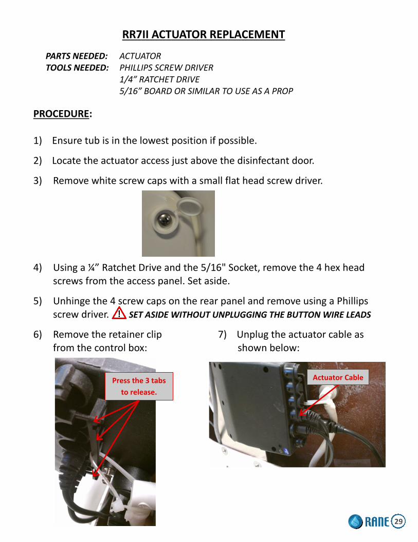
RR7II ACTUATOR REPLACEMENT
PARTS NEEDED: ACTUATOR TOOLS NEEDED: PHILLIPS SCREW DRIVER 1/4” RATCHET DRIVE
5/16” BOARD OR SIMILAR TO USE AS A PROP
PROCEDURE:
1) Ensure tub is in the lowest position if possible.
2) Locate the actuator access just above the disinfectant door.
3) Remove white screw caps with a small flat head screw driver.
4) Using a ¼” Ratchet Drive and the 5/16" Socket, remove the 4 hex head screws from the access panel. Set aside.
5) Unhinge the 4 screw caps on the rear panel and remove using a Phillips screw driver. SET ASIDE WITHOUT UNPLUGGING THE BUTTON WIRE LEADS
6) Remove the retainer clip 7) Unplug the actuator cable as from the control box: shown below:
Press the 3 tabs
to release.
Actuator Cable
29

RR7II ACTUATOR REPLACEMENT (Continued)
8) Remove the lower clevis pin and 2 washers from the actuator. Do this by pulling the cotter pin from it.
9) Unhinge the 4 screw caps on the front panel and remove using a Phillips screw driver. SET ASIDE AND KEEP TRACK OF SCREW COVERS.
10) Lift the front of the tub where shown below and place a 2x4 board or similar to keep propped up. 11) Remove the upper clevis pin and 2 washers from the actuator. Do this by pulling the cotter pin from it.
12) Pull the actuator from the bath tub.
13) Install the new actuator as shown here.
14) Install the lower clevis pin, 2 washers, and cotter pin.
15) Remove the board or prop and let down slowly.
16) Install the lower clevis pin, 2 washers, and cotter pin.
17) Reroute the new actuator cable and plug it in.
18) Re-install the retainer clip.
19) Re-install rear panel.
20) Test the actuator to insure proper functionality.
21) Reinstall front panel.
22) Reinstall actuator access panel.
30

RS8 ACTUATOR REPLACEMENT TOOLS NEEDED: SMALL PLIERS, 2” x 4” x 12” WOOD BOARD, #2 PHILLIPS HEAD SCREWDRIVER
PARTS NEEDED: ACTUATOR
STEP 2: Put 2”x 4”x 12” wood board in place and lower tub until weight is on board and pressure is off of actuator.
STEP 1: Remove back panel (6 screws and white cap covers). Raise the tub to the highest position.
STEP 3: Locate the Control Box. Locate the Connector Clip that holds the Actuator Plug in place. Remove Connector Clip by pressing tabs on each end. Unplug Actuator Plug.
STEP 4: Remove the cotter pin/hairpin from both top and bottom clevis pins with small pliers. Remove the top clevis pin and washers first, then remove lower clevis pin and washers. Remove the defective Actuator.
STEP 5: Install the top of the new Actuator with clevis pin, washers, and cotter pin/hairpin. Connect Actuator Plug-In and install the Connector Clip. Press the raise button to lower the bottom of the Actuator to align with the bottom Actuator mount. When properly aligned, install the bottom clevis pin, washers, and cotter pin/hairpin.
STEP 6: Raise the tub to the highest position and remove the 2”x 4” x 12” wood board. Raise and lower tub to test if Actuator is working properly. Lubricate Actuator Piston with white lithium grease (see Step 1).
STEP 7: Install back panel (6 screws and white cap covers).
Actuator
Plugin
Wood
Board
Actuator
Actuator
Piston
Lower
Clevis Pin
Top
Clevis Pin
31

CABLE DRAIN CORRECTION / ADJUSTMENT
STEP 1: Using a Phillips head screwdriver, remove set screw.
STEP 2: Remove cable drain handle
STEP 3: Use a wrench to remove nut and place as shown in Step 4.
STEP 4: This is the correct way the plate sits.
CORRECT INCORRECT
* When replacing the plate and nut, make sure the nut is secure. STEP 5: Make sure handle moves freely and
does not rub the finish on the tub. If handle is too tight, remove handle and readjust the nut tighter.
32

REPAIR DRAIN STOP / SET SCREW ASSEMBLY
33

Trouble Shooting Institutional
Symptoms Check Solutions
Water too hot or cold when us-ing the thermostatic mixing
valve controls
Check to ensure the water supplies (hot & cold) are within 10% of each
other Consult licensed plumber
Check hot & cold inlet connections. Shut off hot & cold supply valves, dis-
connect supply hoses, and ensure supply hose screens are free of debris
Check to ensure hot & cold supply lines are installed correctly
Reverse connections if backwards
Check thermostatic mixing valve car-tridge.
Shut off hot & cold supply valves, re-move cartridge from body and soak in a cleaning solution overnight, re-install
and test
Check the maximum temperature set-ting.
Contact a RANE authorized dealer for calibration instructions
Air Spa does not turn on
Check GFCI Reset if necessary
Check 15A breaker Reset if necessary
Check that the motor is plugged into the GFCI
Plug in if necessary
Check that the grey cord is connected to the motor and keypad
Re-attach if necessary
Air Spa jets not working, but can hear the motor running
Check to ensure the grey flew hose is connected between the motor and the
manifold
Re-attach if necessary with a 1 ½” hose clamp
Door swings closed by itself
Check gas shock for compression
If replacement needed, contact RANE authorized dealer for replacement
parts
Check screws are tight on the inner and outer hinge bushings
Tighten with a Phillips screw driver if loose
Door will not latch Check door handle and mechanism
are functioning properly
If replacement needed, contact RANE authorized dealer for replacement
parts
Door will not release Check door seal for soap build up
Clean seal with mild soap and water solution, then pat dry.
Apply a rubber dressing
34

Trouble Shooting Institutional (Continued)
Symptoms Check Solutions
Water leaking from door area
Check adjustment on door latch bear-ing
Loosen the 2 Phillips screws and slide the bearing assembly down 1/8” at a
time to make door shut tighter
Check door positioning is equal around the tub rim and seal
Remove hinge cover and loosen the 3 button head screws attached to the
door as necessary
Check door seal
Re-attach if loose with contact ce-ment, suitable for fiberglass. If re-placement needed, contact RANE authorized dealer for replacement
parts
No disinfectant dispensing
Check to ensure there is disinfectant in the bottle
Fill if necessary
Check to ensure the clear disinfectant hose is inserted into the bottle
Insert into bottle if necessary
Check to ensure the clear disinfectant hose is not clogged
Clean hose and re-attach
Check adjustment on the DEMA valve
Adjust small flat tip screw counter-clockwise for more, and clockwise for
less
RR7II Tub will not tilt
Check GFCI Reset if necessary
Check 15A breaker Reset if necessary
Check momentary switches for conti-nuity
If replacement needed, contact RANE authorized dealer for replacement
parts
Check control box on back of tub has power
Carefully remove back cover and pre-vent breakage of the momentary
switch wires. Check the clear circular window on the control box for the light
to be green
Check all connections going to the control box
Ensure all connections are plugged into the control box, and attach if re-
moved
RR7II Tub making grinding noise when tilted back and forth
Check actuator to be the grinding noise
If replacement needed, contact RANE authorized dealer for replacement
parts
35
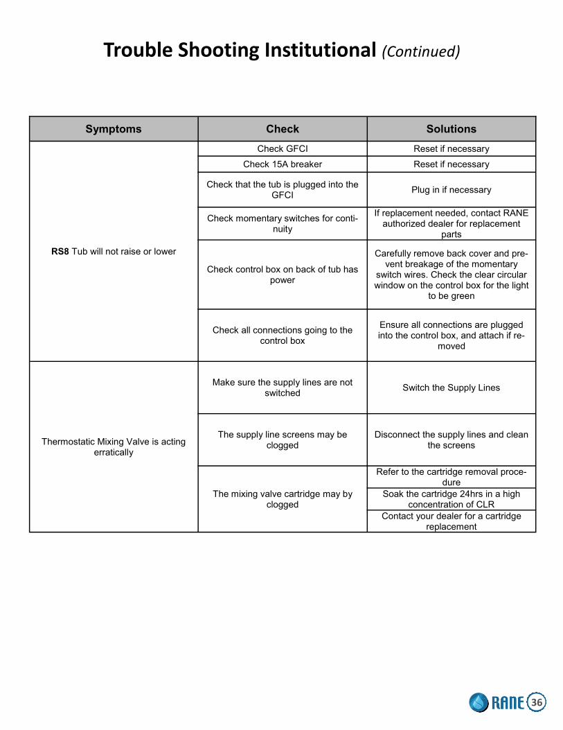
Trouble Shooting Institutional (Continued)
Symptoms Check Solutions
RS8 Tub will not raise or lower
Check GFCI Reset if necessary
Check 15A breaker Reset if necessary
Check that the tub is plugged into the GFCI
Plug in if necessary
Check momentary switches for conti-nuity
If replacement needed, contact RANE authorized dealer for replacement
parts
Check control box on back of tub has power
Carefully remove back cover and pre-vent breakage of the momentary
switch wires. Check the clear circular window on the control box for the light
to be green
Check all connections going to the control box
Ensure all connections are plugged into the control box, and attach if re-
moved
Thermostatic Mixing Valve is acting erratically
Make sure the supply lines are not switched
Switch the Supply Lines
The supply line screens may be clogged
Disconnect the supply lines and clean the screens
The mixing valve cartridge may by clogged
Refer to the cartridge removal proce-dure
Soak the cartridge 24hrs in a high concentration of CLR
Contact your dealer for a cartridge replacement
36

UPGRADES
RR7II RECLINE BUTTON REPLACEMENT
PARTS NEEDED: 4 - FEMALE SLIP-ON QUICK SPADE LUG CONNECTORS 2 - BUTTONS
TOOLS NEEDED: 1 - WIRE CRIMPS 1 - PHILLIPS SCREW DRIVER 1 - OPE END ADJUSTABLE WRENCH
PROCEDURE:
1) Remove white screw caps with a small flat head screw driver
2) Remove 4 Phillips screws from the rear cover.
3) Remove the cover and set aside. KEEP TRACK OF ALL SCREWS.
4) Push the 2 actuator buttons out of the mounting holes. 5) Disconnect the 4 female quick connects from the button lugs. 6) Replace the 4 female quick connects with the provided quick spade lug connects. 7) Remove the mounting nut from each replacement button. 8) Push the buttons into the holes. 9) Tighten the mounting nuts from the back side. 10) Connect the orange & red wire to the 'LOWER' button and green & red wire to the 'RAISE' button. 11) Test the buttons to ensure proper functionality. 12) Re-mount the rear cover using the 6 mounting screws.
37
UPGRADES
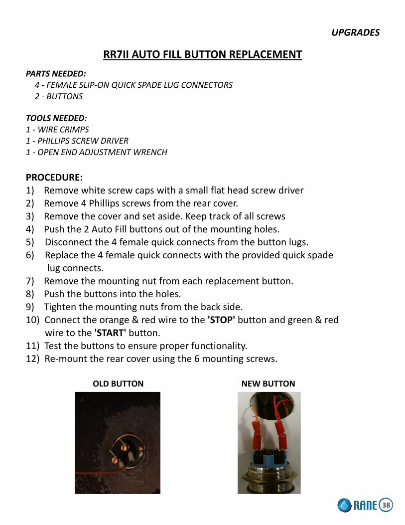
RR7II AUTO FILL BUTTON REPLACEMENT
PARTS NEEDED: 4 - FEMALE SLIP-ON QUICK SPADE LUG CONNECTORS 2 - BUTTONS
TOOLS NEEDED: 1 - WIRE CRIMPS 1 - PHILLIPS SCREW DRIVER 1 - OPEN END ADJUSTMENT WRENCH
PROCEDURE: 1) Remove white screw caps with a small flat head screw driver 2) Remove 4 Phillips screws from the rear cover. 3) Remove the cover and set aside. Keep track of all screws 4) Push the 2 Auto Fill buttons out of the mounting holes. 5) Disconnect the 4 female quick connects from the button lugs. 6) Replace the 4 female quick connects with the provided quick spade
lug connects. 7) Remove the mounting nut from each replacement button. 8) Push the buttons into the holes. 9) Tighten the mounting nuts from the back side. 10) Connect the orange & red wire to the 'STOP' button and green & red wire to the 'START' button. 11) Test the buttons to ensure proper functionality. 12) Re-mount the rear cover using the 6 mounting screws. OLD BUTTON NEW BUTTON
38

UPGRADES
RS8 HEIGHT ADJUST 2-BUTTON REPLACEMENT
PARTS NEEDED: 4 - FEMALE SLIP-ON QUICK SPADE LUG CONNECTORS 2 - BUTTONS 2 - WIRE TIES
TOOLS NEEDED: 1 - WIRE CRIMPS 1 - PHILLIPS SCREW DRIVER 1 - DIAGONAL CUTTERS 1 - OPEN END ADJUSTABLE WRENCH
PROCEDURE: 1) Remove white screw caps with a small
flat head screw driver 2) Remove 6 Phillips screws from the rear
cover. 3) Remove the cover and set aside. KEEP TRACK OF ALL SCREWS.
4) Remove 2 Phillips screws from the battery pack. Allow battery pack to hang from tub 5) Use diagonal cutters to remove 2 wire ties from the Air Spa manifold (if equipped). Allow Air Spa manifold to hang free 6) Push the 2 actuator buttons out of the mounting holes. 7) Disconnect the 4 female quick connects from the button lugs. 8) Replace the 4 female quick connects with the quick spade lug connects. 9) Remove the mounting nut from each replacement button. 10) Push the buttons into the holes. 11) Tighten the mounting nuts from the back side. 12) Connect the orange & red wire to the 'LOWER' Button and green & red wire to the 'RAISE' button. 13) Test the buttons to ensure proper functionality. 14) Use the provided wire ties to re-mount the Air Spa manifold. 15) Re-mount battery pack using the 2 mounting screws. 16) Re-mount rear cover using the 6 mounting screws.
39

UPGRADES
RS8 HEIGHT ADJUST 4-BUTTON REPLACEMENT
PARTS NEEDED: 8 - FEMALE SLIP-ON QUICK SAPDE LUG CONNECTORS 4 - BUTTONS
TOOLS NEEDED: 1 - WIRE CRIMPS 1 - PHILLIPS SCREW DRIVER 1 - OPEN END ADJUSTABLE WRENCH
PROCEDURE: 1) Remove white screw caps with a small flat head screw driver
2) Remove 6 Phillips screws from the rear cover.
3) Remove the cover and set aside. KEEP TRACK OF ALL SCREWS.
4) Push the 4 actuator buttons out of the mounting holes.
5) Disconnect the 8 female quick connects from the button lugs.
6) Replace the 8 female quick connects with the provided quick
spade lug connects.
7) Remove the mounting nut from each replacement button.
8) Push the buttons into the holes.
9) Tighten the mounting nuts from the back side.
10) Connect the orange & red wire to the 'LOWER' button and green & red wire
to the 'RAISE' button.
11) Test the buttons to ensure proper
functionality.
12) Re-mount the rear cover using the
6 mounting screws.
40

UPGRADES
RS8 AUTO FILL BUTTON REPLACEMENT
PARTS NEEDED: 4 - FEMALE SLIP-ON QUICK SPADE LUG CONNECTORS 2 - BUTTONS
TOOLS NEEDED: 1 - WIRE CRIMPS 1 - PHILLIPS SCREW DRIVER 1 - OPEN END ADJUSTABLE WRENCH
PROCEDURE:
1) Remove white screw caps with a small flat head screw driver
2) Remove 6 Phillips screws from the rear cover.
3) Remove the cover and set aside. KEEP TRACK OF ALL SCREWS.
4) Push the 2 Auto Fill buttons out of the mounting holes.
5) Disconnect the 4 female quick connects from the button lugs.
6) Replace the 4 female quick connects with the provided quick spade
lug connects.
7) Remove the mounting nut from each replacement button.
8) Push the buttons into the holes.
9) Tighten the mounting nuts from the back side.
10) Connect the orange & red wire to the 'STOP' button and green & red
wire to the 'START' button.
11) Test the buttons to ensure proper functionality.
12) Re-mount the rear cover using the 6 mounting screws.
41

UPGRADES
RR7-II, RK12, RG9, RB14 THERMOMETER REPLACEMENT PROCEDURE PARTS NEEDED: 1 - THERMOMETER TOOLS NEEDED: 1 - WIRE CRIMPS, 1 - PHILLIPS SCREW DRIVER , 1 - 11/16" WRENCH, 1 - 7/8" WRENCH
STEP 1: Turn cold water supply off and identify the Disinfectant Valve System, which consists of a Metering Knob Assembly and Disinfectant Injector.
STEP 2: Using the 11/16” wrench, remove the smaller bushing first. Pull out the smaller bushing and probe. Remove larger adapter bushing with 7/8” wrench. See Fig. 1
STEP 3: Remove the 3 small Phillips head screws and pull out thermometer body and probe.
STEP 4: Wrap new Adapter Bushing threads with Teflon tape and insert into copper threaded pipe using 7/8” wrench. Tighten well.
STEP 5: Insert new thermometer body and probe through faceplate.
STEP 6: Wrap small bushing threads with Teflon tape and insert probe and small bushing (fig. 1) into adapter bushing. Tighten with 11/16” wrench.
STEP 7: Insert 3 small Phillips head screws that secure thermometer body to faceplate, see Step 3.
FIGURE 1
STEP 8: Turn main water supply on. Test for leaks at bushings. If leak occurs, try tightening more. If leak still occurs, turn main water supply off and repeat Step 4 and Step 6.
STEP 9: Re-install access panel.
3 Screws
Small Bushing & Probe
Adapter Bushing
Adapter Bushing
42
UPGRADES
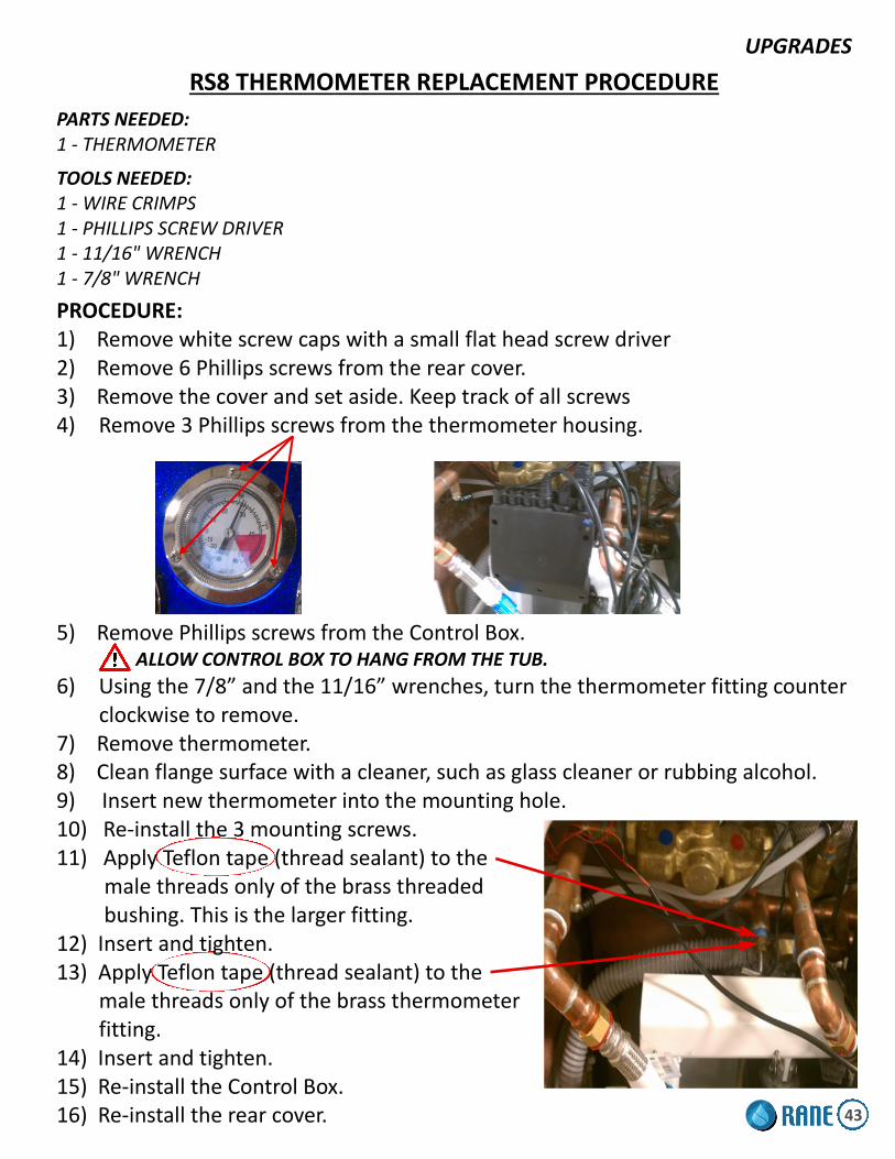
RS8 THERMOMETER REPLACEMENT PROCEDURE
PARTS NEEDED: 1 - THERMOMETER
TOOLS NEEDED: 1 - WIRE CRIMPS 1 - PHILLIPS SCREW DRIVER 1 - 11/16" WRENCH 1 - 7/8" WRENCH
PROCEDURE: 1) Remove white screw caps with a small flat head screw driver 2) Remove 6 Phillips screws from the rear cover. 3) Remove the cover and set aside. Keep track of all screws 4) Remove 3 Phillips screws from the thermometer housing.
5) Remove Phillips screws from the Control Box. ALLOW CONTROL BOX TO HANG FROM THE TUB.
6) Using the 7/8” and the 11/16” wrenches, turn the thermometer fitting counter clockwise to remove. 7) Remove thermometer. 8) Clean flange surface with a cleaner, such as glass cleaner or rubbing alcohol. 9) Insert new thermometer into the mounting hole. 10) Re-install the 3 mounting screws. 11) Apply Teflon tape (thread sealant) to the male threads only of the brass threaded bushing. This is the larger fitting. 12) Insert and tighten. 13) Apply Teflon tape (thread sealant) to the male threads only of the brass thermometer fitting. 14) Insert and tighten. 15) Re-install the Control Box. 16) Re-install the rear cover. 43

INSTALL A DISINFECTANT WAND UPGRADE KIT (# 1904+H)
INSTALLATION: RG9 1. Place mounting bracket behind white disinfectant tray as shown in Figure 1a & 1b. Make sure the mounting bracket is snug against the top and side lip of the white disinfectant tray, which helps hold it in place (see Figure 1b). 2. Mark the location of the hole in the mounting bracket as shown in Figure 1b. 3. Drill a 3/16” hole through the mounting bracket and white disinfectant tray. 4. Using the screw and kept nut provided, assemble as shown in Figure 1a & 1b. 5. Install and hand tighten snuggly the disinfectant hose fitting and washer to the wand. 6. Using an adjustable wrench, tighten the red coiling disinfectant hose to the disinfectant hose fitting.
* Teflon plumbing tape may be needed on the threads at the end of the red coiling disinfectant hose if a leak occurs.*
INSTALLATION: RR7 1. Remove the existing mounting bracket. 2. Using the screw and kept nut provided, replace and assemble the new mounting bracket as shown in Figure 2a. 3. If there is not an existing mounting bracket, align the mounting bracket on the side of the disinfectant cabinet you prefer and drill a 3/16” hole through the mounting bracket and lip of the cabinet. 4. Install and hand tighten snuggly the disinfectant hose fitting and washer to the end of the wand as shown in Figure 2b. 5. Using an adjustable wrench, tighten the end of the red coiling disinfectant hose to the disinfectant hose fitting. * Teflon plumbing tape may be needed on the threads at the end of the red
coiling disinfectant hose if a leak occurs. *
Disinfectant Tray
Mounting Bracket
Disinfectant Hose Fitting
FIGURE 1a
**Make sure mounting bracket is snug against top and side lip
Drill 3/16 hole here
FIGURE 1b
FIGURE 2a
Mounting Bracket
FIGURE 2b
Disinfectant Hose Fitting
Washer
Mounting bracket can be installed on either side.
44

INSTALL A DISINFECTANT WAND UPGRADE KIT (# 1904+H) (Continued)
INSTALLATION: RS8, RK12, & RB14-IM 1. Open the white hinged screw caps on the rear access panel (RS8 and RK12). 2. Remove rear access panel using a Phillips screwdriver. 3. Remove the old wand holster. 4. Mount the new holster, using the existing hole in the fiberglass, with the wider opening pointing up and the narrower opening pointing down (holster is tapered). Mark the second hole that needs to be drilled. 5. Drill a 3/16” hole through the fiberglass. 6. Use the remaining screw, washer, and kept nut provided, assemble as shown in Figure 3. 7. Reassemble the rear access panel (RS8, RK12). 8. Install and hand tighten snuggly the wand and washer directly into the existing disinfectant wand hose.
FIGURE 3
Narrower Opening
Wider Opening Washer
45
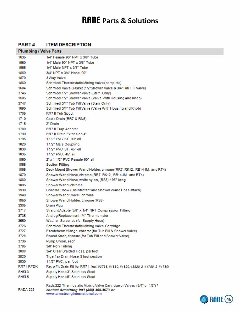
RANE Parts & Solutions
46

RANE Parts & Solutions (Continued)
47

RANE Parts & Solutions (Continued)
48

RANE Parts & Solutions (Continued)
49