Embed Size (px)
Citation preview
Pressure Relief System Developments in the Next
Decade
Valerie Magyari
10th Annual IPEIA (formerly NPEC) Conference Banff Centre in Banff Alberta, Canada
February 1 – 3, 2006
2
Presentation Outline
• Introduction
• Recent trends in industry standards related to the design, installation and inspection of pressure relieving systems– Less prescriptive
– Use of Risk assessment
– Places more responsibility on the User
• Use of system design in place of providing pressure relief devices in accordance with proposed modifications to ASME Code UG-140 (Code Case 2211)
• ASME Code Appendix M modifications related to use of isolation valves in pressure relief path
• Use of Risk Based Inspection (RBI) to set intervals for testing, inspecting and overhauling pressure relief devices
• Detailed review of the API RBI PRD Module
• Summary
3
ASME Code Case 2211
• Uses system design in place of a relief devices for Section VIII vessels
• Presented in 1996• Revised in 1999• WRC Bulletin 498, January 2005 provides
guidance on the use of Code Case 2211• Currently being rewritten by API/ASME Task
Force to be included as UG-140 in ASME Section VIII
– Going to ASME SC-SVR for review in February
4
ASME Code Case 2211
• Code Case permits use of process design rather than relief devices– All overpressure analyses and relief system
documentation remain the same– Code Case will be expanded to consider all facets of the
process, in particular if no overpressure can occur– Overpressure protection requirements will be based on
frequency and degree of overpressure (Risk)– where personnel are qualified
• Can be applied if the vessel is not exclusively in air, water, or steam service unless these services are critical to preventing the release of fluids that may result in safety or environmental hazards
• The decision to provide a vessel with overpressure protection by system design is the responsibility of the User
5
ASME Code Case 2211• ASME Code Case 2211 gives the following guidance for
using process design in place of relief valves– Application is responsibility of user
– The User shall ensure that the MAWP of the vessel is greater than the highest pressure which can reasonably be expected to be achieved by the system
– Implementation requires increased User responsibility and should only be employed where personnel are qualified
6
ASME Code Case 2211• A multidisciplinary team using an organized,
systematic approach such as those listed below shall be used
– Hazards and Operability Analysis (HazOp)– Failure Modes– Effects and Criticality Analysis (EMECA)– Fault Tree Analysis– Event Tree Analysis – “What-If” Analysis– or other similar methodology
• The analysis shall be conducted by an engineer(s) experienced in the applicable analysis methodology
• Any over pressure concerns, which are identified, shall be evaluated by an engineer(s) experienced in pressure vessel design and analysis
• The results of the analysis shall be documented, and signed by the individual in charge of the operation of the vessel
7
ASME Code Case 2211• All documentation must be complete and prior to
initial operation the documentation shall be made available to the regulatory and enforcement authorities having jurisdiction at the site where the vessel will be installed
– Detailed Process and Instrument Flow Diagrams (P&IDs), showing all pertinent elements of the system associated with the vessel
– A description of all credible operating and upset scenarios, including scenarios, which result from equipment and instrumentation malfunctions.
– An analysis showing the maximum pressure which can result from each of the scenarios examined
– A detailed description of any instrumentation and control system which is used to limit the system pressure, including the identification of all truly independent redundancies and a reliability evaluation (qualitative or quantitative) of the overall safety system
8
ASME Code Case 2211
• The User of this Code Case is cautioned that prior Jurisdictional acceptance may be required
• This Case number shall be shown on the Manufacturer’s Data Report for pressure vessels that will be provided with overpressure protection by system design
• It shall be noted on the Data Report that prior Jurisdictional acceptance may be required
9
ASME Code Case 2211
• Can Code Case 2211 be used to eliminate certain scenarios with the potential to reduce the size of the PRV?
– No, it is currently written to eliminate relief devices, API/ASME task force revising
– However, ASME never has told the user how to size the relief device - Only that a vessel needs a relief device
– Therefore, the user defines the scenarios – System design has always been permitted to prevent a
scenario from being considered– The user must assure that this is safe and within any
established risks of the user– All good engineering practices must be followed
10
H eater
R eactor
Feed
R G C
H P S epara tor
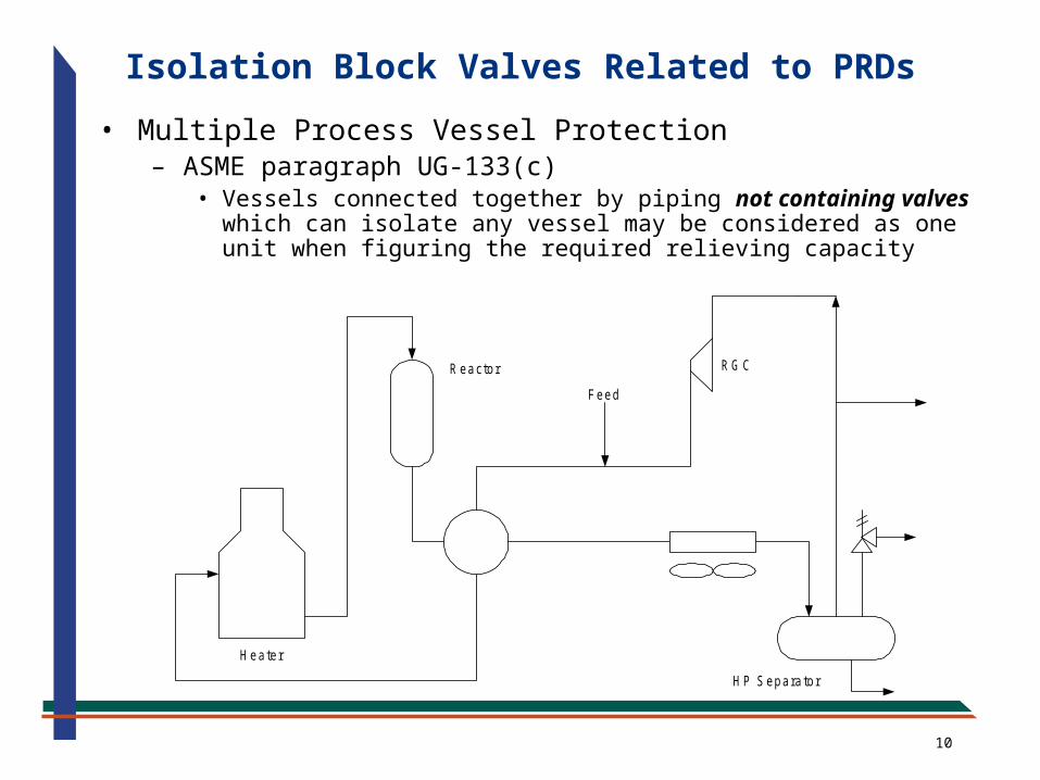
Isolation Block Valves Related to PRDs
• Multiple Process Vessel Protection– ASME paragraph UG-133(c)
• Vessels connected together by piping not containing valves which can isolate any vessel may be considered as one unit when figuring the required relieving capacity
11
cw
S team
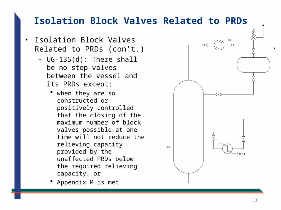
Isolation Block Valves Related to PRDs
• Isolation Block Valves Related to PRDs (con’t.)– UG-135(d): There shall be
no stop valves between the vessel and its PRDs except: when they are so
constructed or positively controlled that the closing of the maximum number of block valves possible at one time will not reduce the relieving capacity provided by the unaffected PRDs below the required relieving capacity, or
Appendix M is met
12
Isolation Block Valves Related to PRDs
• Previous Appendix M– Stop valves could always be installed on the upstream and
downstream of a relief valve to permit inspection, testing and maintenance if the following conditions are met1. Administrative Controls are provided to prevent unauthorized
closure of the valve2. Mechanical locking devices are installed on the valves 3. Valve failure controls are provided to prevent accidental closure 4. Procedures are in place to provide other pressure relief when
the relief valve is out of service– An authorized person shall continuous monitor the pressure condition
and be able to respond promptly by opening other valves or by closing the source of overpressure
– Person shall be dedicated with no other duties– Person shall have documented procedures and training– System should be isolated only for the time required– Time required should be kept to an absolute minimum
13
Isolation Block Valves Related to PRDs
• Previous Appendix M– Stop valves may be installed between vessels with a single
relief device if the pressure exclusively originates from an outside source and closing a valve will isolate the protected vessel from the source• e. g. Two vessels in series with the relief device on the first
vessel and the only source of overpressure is flow going into the first vessel
14
Isolation Block Valves Related to PRDs
• Unpublished Interpretation (1997-98) by ASME very troublesome to API– ED&C company requested an interpretation from ASME regarding
block valves used within a system of vessels– In 9/98, ASME SC-SVR initially agreed that Appendix M applied to a
system of vessels with block valve in between– ASME SC VIII main committee reversed the position in 11/98– Bottom line: Does Appendix M apply to any isolation valve installed
for inspection and maintenance purposes or just those installed for inspection and maintenance of pressure relief valves
– API feels that good engineering practice should allow it• API RP521 allowed the use of administrative procedures on
isolation valves to eliminate the need for a PRV to protect against block-in scenario
• ASME Code – “Installation is responsibility of the User”– Most major oil companies allowed it, elimination of isolation valves
in relief path would be extremely costly to industry– API/ASME Task Force reached consensus on Appendix M
modifications
15
Isolation Block Valves Related to PRDs
• Recent ASME revisions to Appendix M– Paragraph M-5(g) Stop valves, including remote
operated valves, may be provided in the relief path where there is normally a process flow if the following are met:
– M-5(g)(1) The flow resistance of the stop valve does not reduce the relieving capacity required
– M-5(g)(2) Closure of the valve will be apparent to the operator such that corrective action can be taken and:a) If the pressure due to closure of the valve does not exceed
116% of MAWP, then no controls are requiredb) If the pressure due to closure of the valve does not exceed
hydrostatic test pressure multiplied by the ratio of the stress values at hydro and operating temperatures, and considering corrosion, then Administrative Controls and Mechanical Locking Elements are required
c) If the pressure exceeds that in b), then the stop valves shall be eliminated or provide Administrative Controls, Mechanical Locking Elements, Valve Failure Controls and Valve Operation Controls or provide a relief device on each vessel
16
Isolation Block Valves Related to PRDs
• Recent ASME revisions to Appendix M– Paragraph M-5(h) Full area stop valve(s) located in the
relief path of equipment where fire is the only potential source of overpressure do not require mechanical locking elements, valve operation controls, or valve failure controls provide the user has documented operating procedures requiring that equipment isolated from its pressure relief path is depressured and free of all liquids
17
Isolation Block Valves Related to PRDs
• Administrative Controls for stop valves are procedures intended to ensure that personnel actions do not compromise the overpressure protection of the equipment. Administrative Controls for stop valves include:– (1) Documented Operation and Maintenance Procedures– (2) Operator and Maintenance Personnel Training in the
above procedures• Mechanical Locking Elements are physical barriers to
valve operation and they must be deliberately removed to close the valve, e.g. chain locks, plastic or metal straps, car seals, etc.
• Valve Failure Controls are measures taken in the design and installation of a valve to assure that it does not fail closed
18
Isolation Block Valves Related to PRDs
• Valve Operation Controls are devices used to ensure that stop valves are in the proper (open/closed) position– Mechanical interlocks to prevent closing of a valve before
an alternate valve is fully opened– Instrument interlocks similar to mechanical interlocks but
use instrumentation with permissives and interlocks to prevent valve closures
– Three-way valves that are designed to provide an open flow path before the valve is closed
• Management System– The collective application of administrative controls, valve
operation controls and valve failure controls
19
• User has the responsibility to establish and maintain a management system to ensure a vessel is not operated without overpressure protection1. Decides and specifies if the overpressure system will allow the use of stop
valves2. Establishes the overpressure philosophy and the administrative controls
requirements3. Establishes the required levels of reliability, redundancy, and maintenance of
instrumentation interlocks, if used4. Establishes procedures to ensure the equipment is adequately protected5. Ensures that authorization to operate stop valves is clear and personnel
trained6. Establishes management systems to ensure that administrative controls are
effective7. Establishes the analysis procedures and basis to be used in determining the
potential levels of pressure if the stop valves are closed8. Ensures that the analysis in (7) is done by qualified personnel9. Ensures that the other system components are acceptable to the levels found
in (7)10. Ensures that the results determined are documented, reviewed and accepted
in writing by the individual responsible for the operation of the vessels and valves
11. Ensures that the administrative controls are reviewed and accepted in writing by the individual responsible for the operation of the vessels and valves
Isolation Block Valves Related to PRDs
20
Isolation Block Valves Related to PRDs
• Requirements for the Procedural/Management System – Procedures shall specify that valves requiring mechanical
locking elements, and/or valve operation controls, and/or valve failure controls shall be documented and clearly identified as such
– The management system shall document the administrative controls, (training and procedures), the valve controls, and the performance of the administrative controls in an auditable form for management review
21
API 510 Inspection Code
• API 510 Inspection Code– Paragraph 4.5 has special requirements for organizations
maintaining pressure relief valves– Pressure relief valves shall be tested at intervals that are
frequent enough to verify that the valves perform reliably– Intervals between pressure relieving device testing or
inspection should be determined by the performance of the devices in the particular service concerned and may be increased to a maximum of 10 years
– Latest version of API 510 allows the use of RBI to set intervals
22
Risk-Based Inspection (RBI)• High risk events are high probability events resulting in
large consequences or losses• Low risk events are unlikely events resulting in no
significant losses• Evaluates POF and COF • Risk = POF x COF
– Could be expressed quantitatively in $/year, ft2/year– Could be expressed qualitatively - Low to High
• Initial inspection intervals can be justified (not arbitrary) and typically start higher
• RBI should result in an inspection interval based on the company’s risk tolerance
• Primary objective of RBI is to manage risk, and better focus limited inspection resources
• Rewrite of API 581 includes RBI Methodology for PRDs• API RBI Software revision 7.0 includes PRD Module
23
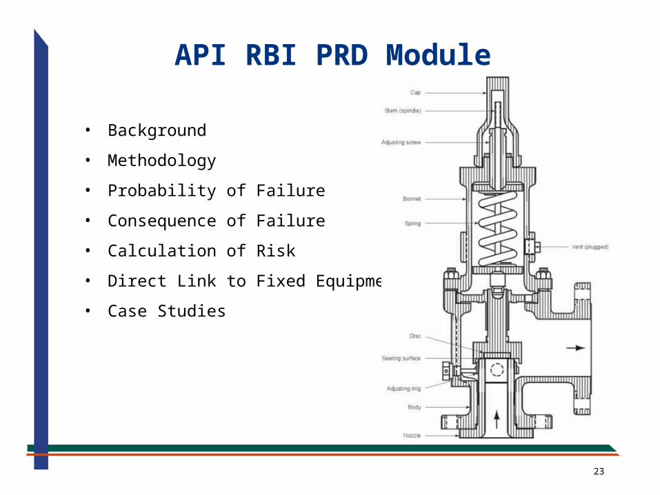
API RBI PRD Module
• Background
• Methodology
• Probability of Failure
• Consequence of Failure
• Calculation of Risk
• Direct Link to Fixed Equipment
• Case Studies
24
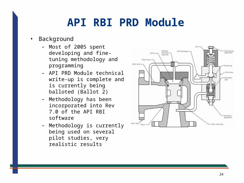
• Background– Most of 2005 spent
developing and fine-tuning methodology and programming
– API PRD Module technical write-up is complete and is currently being balloted (Ballot 2)
– Methodology has been incorporated into Rev 7.0 of the API RBI software
– Methodology is currently being used on several pilot studies, very realistic results
API RBI PRD Module
25
• Methodology– Highly Quantitative– Risk for PRDs are calculated for two failure modes– Fail to Open (FAIL)
• PRD does not open on demand during an overpressure scenario (fire, blocked discharge, CV failure, loss of cooling, power failure, etc.)
• Overpressures can be well over normal operating, for some scenarios burst pressure (≈ 4 x Design pressure)
• Evaluate loss of containment (leaks or ruptures) from the protected equipment at the overpressure
• Includes repair costs of equipment, personnel injury costs, environmental costs and loss of production costs
– Leakage Failure (LEAK)• PRD leaks in-service• Considers cost of lost fluid inventory, repair costs, and production
losses if downtime is required to repair PRD
– RISK = POF x COF + POL x COL, $/year
API RBI PRD Module
26
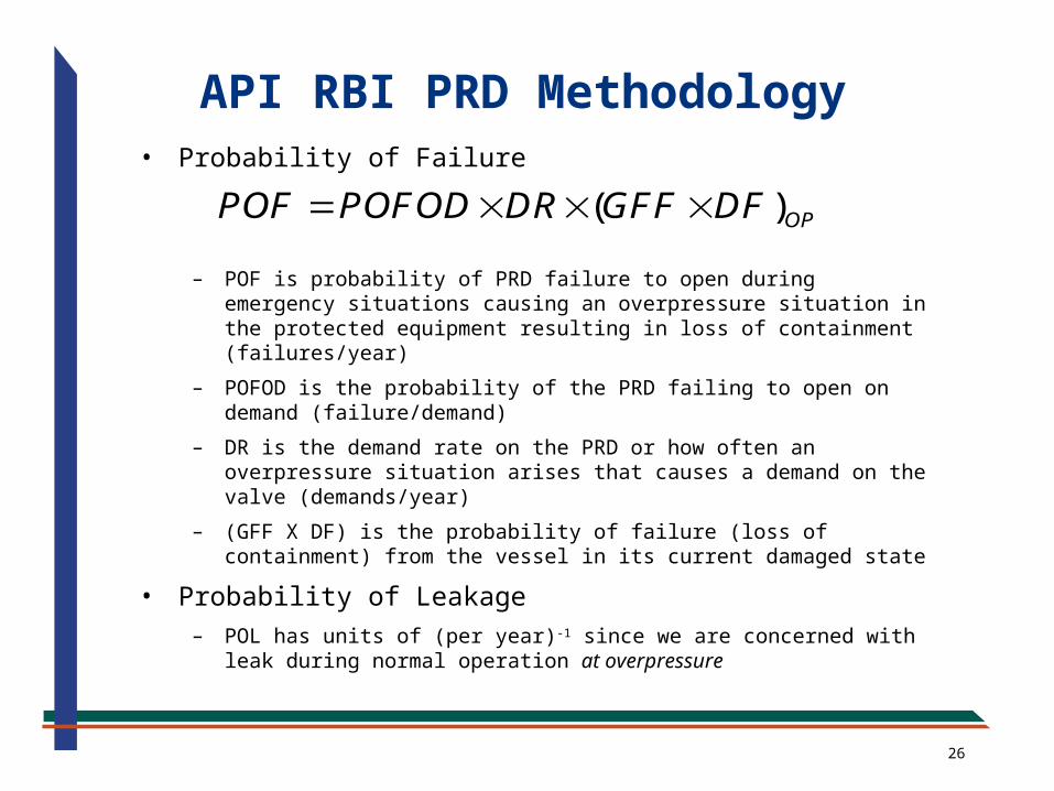
• Probability of Failure
– POF is probability of PRD failure to open during emergency situations causing an overpressure situation in the protected equipment resulting in loss of containment (failures/year)
– POFOD is the probability of the PRD failing to open on demand (failure/demand)
– DR is the demand rate on the PRD or how often an overpressure situation arises that causes a demand on the valve (demands/year)
– (GFF X DF) is the probability of failure (loss of containment) from the vessel in its current damaged state
• Probability of Leakage– POL has units of (per year)-1 since we are concerned with leak
during normal operation at overpressure
( )OPPOF POFOD DR GFF DF
API RBI PRD Methodology
27
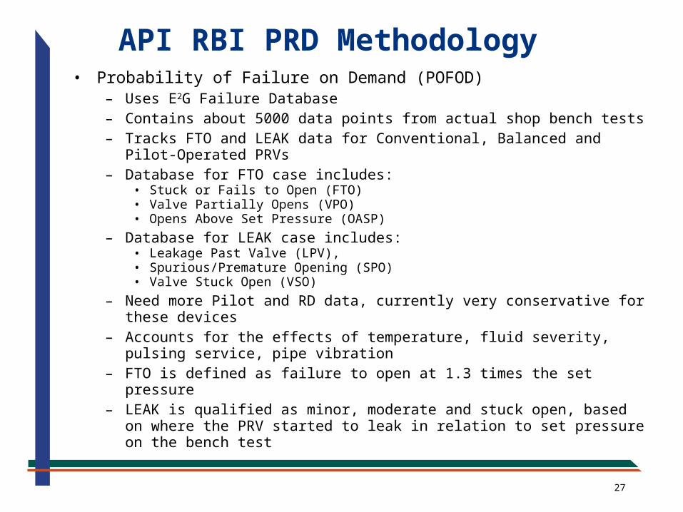
• Probability of Failure on Demand (POFOD)– Uses E2G Failure Database– Contains about 5000 data points from actual shop bench tests– Tracks FTO and LEAK data for Conventional, Balanced and Pilot-
Operated PRVs– Database for FTO case includes:
• Stuck or Fails to Open (FTO)• Valve Partially Opens (VPO)• Opens Above Set Pressure (OASP)
– Database for LEAK case includes:• Leakage Past Valve (LPV),• Spurious/Premature Opening (SPO)• Valve Stuck Open (VSO)
– Need more Pilot and RD data, currently very conservative for these devices
– Accounts for the effects of temperature, fluid severity, pulsing service, pipe vibration
– FTO is defined as failure to open at 1.3 times the set pressure– LEAK is qualified as minor, moderate and stuck open, based on
where the PRV started to leak in relation to set pressure on the bench test
API RBI PRD Methodology
28
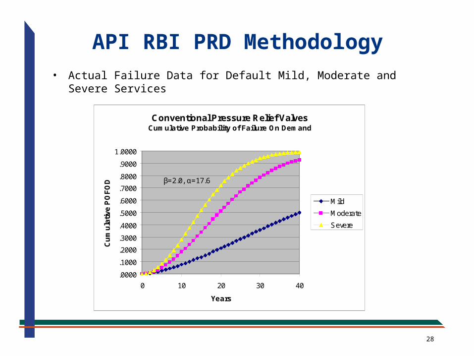
• Actual Failure Data for Default Mild, Moderate and Severe Services
Conventional Pressure Relief ValvesCumulative Probability of Failure On Demand
.0000
.1000
.2000
.3000
.4000
.5000
.6000
.7000
.8000
.9000
1.0000
0 10 20 30 40
Years
Cu
mu
lati
ve P
OF
OD
Mild
Moderate
Severe
β=2.0, α=17.6
β=1.9, α=23.9
β=1.6, α=50.5
API RBI PRD Methodology
29
API RBI PRD Methodology
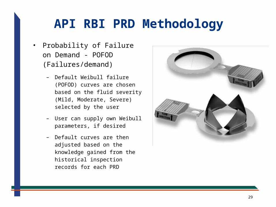
• Probability of Failure on Demand - POFOD (Failures/demand)
– Default Weibull failure (POFOD) curves are chosen based on the fluid severity (Mild, Moderate, Severe) selected by the user
– User can supply own Weibull parameters, if desired
– Default curves are then adjusted based on the knowledge gained from the historical inspection records for each PRD
30
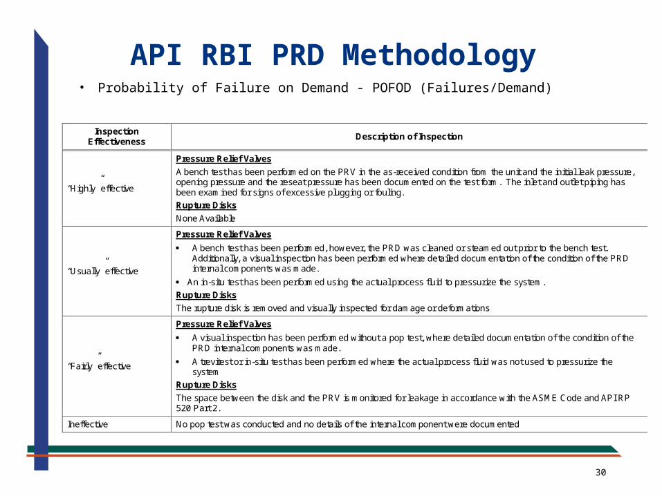
API RBI PRD Methodology• Probability of Failure on Demand - POFOD (Failures/Demand)
Inspection Effectiveness
Description of Inspection
“Highly” effective
Pressure Relief Valves
A bench test has been performed on the PRV in the as-received condition from the unit and the initial leak pressure, opening pressure and the reseat pressure has been documented on the test form. The inlet and outlet piping has been examined for signs of excessive plugging or fouling.
Rupture Disks
None Available
“Usually” effective
Pressure Relief Valves
A bench test has been performed, however, the PRD was cleaned or steamed out prior to the bench test. Additionally, a visual inspection has been performed where detailed documentation of the condition of the PRD internal components was made.
An in-situ test has been performed using the actual process fluid to pressurize the system.
Rupture Disks
The rupture disk is removed and visually inspected for damage or deformations
“Fairly” effective
Pressure Relief Valves
A visual inspection has been performed without a pop test, where detailed documentation of the condition of the PRD internal components was made.
A trevitest or in-situ test has been performed where the actual process fluid was not used to pressurize the system
Rupture Disks
The space between the disk and the PRV is monitored for leakage in accordance with the ASME Code and API RP 520 Part 2.
Ineffective No pop test was conducted and no details of the internal component were documented
31
• Demand Rate - DR (demands/year)
– The methodology recognizes the fact that the PRD is not needed the majority of the time that it is in-service, it is only needed during an overpressure event (fire, loss of power, blocked discharge, etc.)
– These overpressure events are rare; demand rates are typically on the order of 1/10 years but some are extremely rare, such as fire; 1/250 years
– Includes a Demand Rate Reduction Factor (DRRF) to account for factors in the process design that may assist in reducing the demand rate on a PRD
• Fire-fighting facilities
• Process control Layers of Protection (LOPA)
API RBI PRD Methodology
32
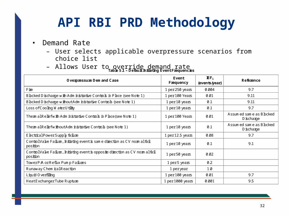
• Demand Rate– User selects applicable overpressure scenarios from choice list– Allows User to override demand rate
API RBI PRD Methodology
Table 5.1 – Default Initiating Event Frequencies
Overpressure Demand Case Event
Frequency IEFi
(events/year) Reference
Fire 1 per 250 years 0.004 9.7
Blocked Discharge with Administrative Controls in Place (see Note 1) 1 per 100 Years 0.01 9.11
Blocked Discharge without Administrative Controls (see Note 1) 1 per 10 years 0.1 9.11
Loss of Cooling Water Utility 1 per 10 years 0.1 9.7
Thermal Relief with Administrative Controls in Place(see Note 1) 1 per 100 Years 0.01 Assumed same as Blocked
Discharge
Thermal Relief without Administrative Controls (see Note 1) 1 per 10 years 0.1 Assumed same as Blocked
Discharge
Electrical Power Supply failure 1 per 12.5 years 0.08 9.7
Control Valve Failure, Initiating event is same direction as CV normal fail position
1 per 10 years 0.1 9.1
Control Valve Failure, Initiating event is opposite direction as CV normal fail position
1 per 50 years 0.02
Tower P/A or Reflux Pump Failures 1 per 5 years 0.2
Runaway Chemical Reaction 1 per year 1.0
Liquid Overfilling 1 per 100 years 0.01 9.7
Heat Exchanger Tube Rupture 1 per 1000 years 0.001 9.5
33
• (GFF x DF) is the probability of failure (loss of containment) from the vessel in its current damaged state
– For fixed equipment RBI, this value is determined at operating pressure
– Unlike fixed equipment RBI, PRD RBI is performed at much higher overpressures
• Software calculates potential overpressure if the PRD fails to open on demand
• Overpressure increases release amount and also increases probability of leaks and ruptures (GFFs are increased as a function of overpressure)
• Some overpressure scenarios (fire, power failure) may result in rupture, if the PRD fails to open on demand
API RBI PRD Methodology
34
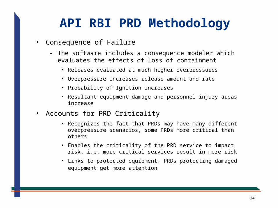
• Consequence of Failure
– The software includes a consequence modeler which evaluates the effects of loss of containment
• Releases evaluated at much higher overpressures
• Overpressure increases release amount and rate
• Probability of Ignition increases
• Resultant equipment damage and personnel injury areas increase
• Accounts for PRD Criticality• Recognizes the fact that PRDs may have many different
overpressure scenarios, some PRDs more critical than others
• Enables the criticality of the PRD service to impact risk, i.e. more critical services result in more risk
• Links to protected equipment, PRDs protecting damaged equipment get more attention
API RBI PRD Methodology
35
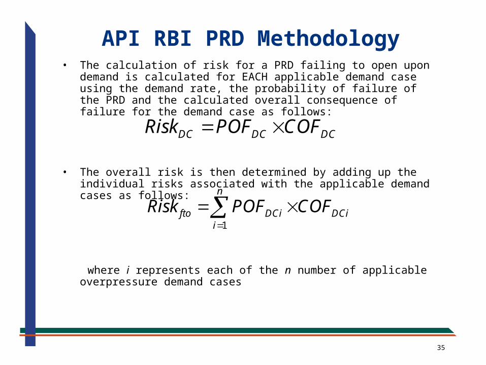
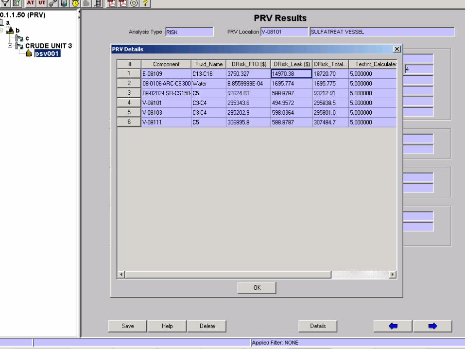
• The calculation of risk for a PRD failing to open upon demand is calculated for EACH applicable demand case using the demand rate, the probability of failure of the PRD and the calculated overall consequence of failure for the demand case as follows:
• The overall risk is then determined by adding up the individual
risks associated with the applicable demand cases as follows:
where i represents each of the n number of applicable
overpressure demand cases
DC DC DCRisk POF COF
1
n
fto DCi DCii
Risk POF COF
API RBI PRD Methodology
36
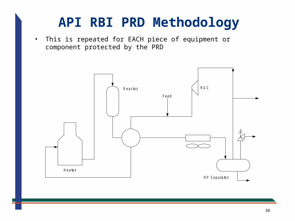
• This is repeated for EACH piece of equipment or component protected by the PRD
H eater
R eactor
Feed
R G C
H P S epara tor
API RBI PRD Methodology
37
38
39
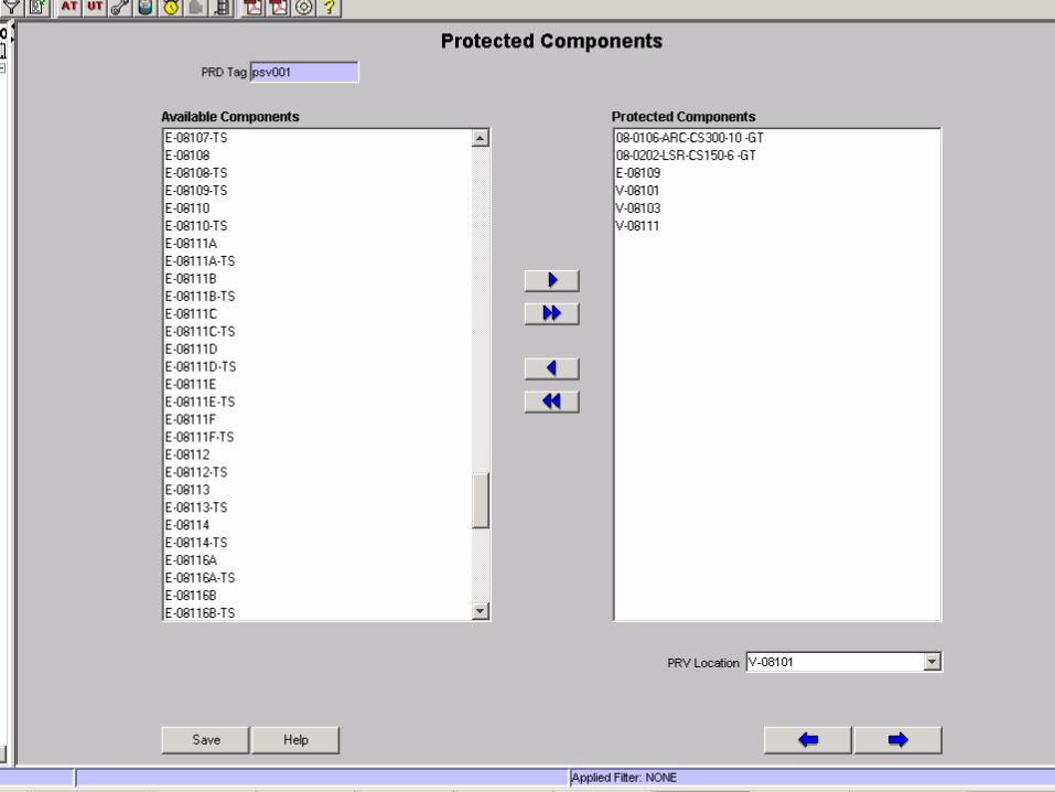
• Direct Link to Fixed Equipment
– PRD Protected Components table which links PRDs to their protected equipment
• Handles equipment protected by multiple PRDs
• Handles multiple pieces of equipment protected by common PRD(s)
– Significantly reduces amount of input for PRDs. Links PRD to inventory group, operating and design conditions, fluid properties and most importantly to the damage state of the protected equipment
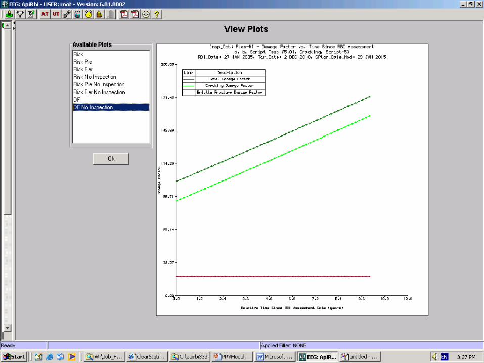
– Recognizes the fact that damaged vessels are at higher risk due to a failed PRD than undamaged vessels
– Also, since damage factor of the protected equipment increases as a function of time so does the risk associated with the PRD protecting it
API RBI PRD Module
40
41
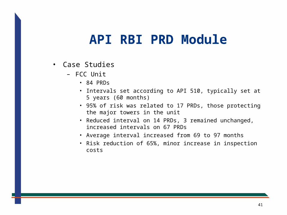
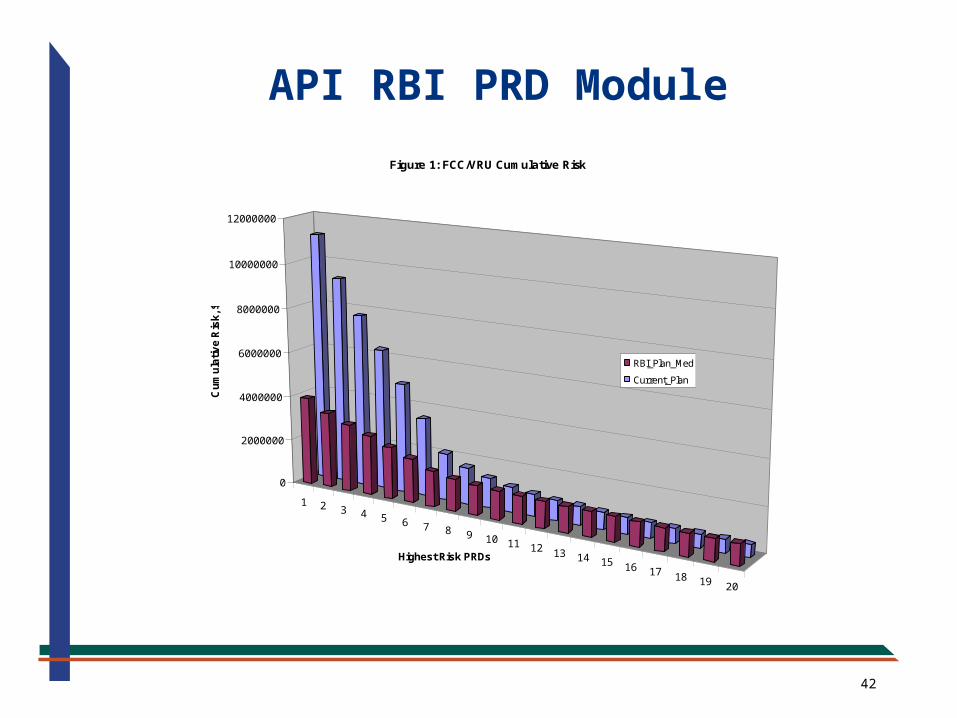
• Case Studies– FCC Unit
• 84 PRDs• Intervals set according to API 510, typically set at 5 years (60
months)• 95% of risk was related to 17 PRDs, those protecting the major
towers in the unit• Reduced interval on 14 PRDs, 3 remained unchanged,
increased intervals on 67 PRDs• Average interval increased from 69 to 97 months• Risk reduction of 65%, minor increase in inspection costs
API RBI PRD Module
42
1 2 3 4 5 6 7 8 9 10 11 12 13 14 15 16 17 18 19 20
0
2000000
4000000
6000000
8000000
10000000
12000000C
um
ula
tiv
e R
isk
, $
Highest Risk PRDs
Figure 1: FCC/VRU Cumulative Risk
RBI_Plan_Med
Current_Plan
PSV-4403
PSV-4406
PSV-478
PSV-468
PSV-467
PSV-469
PSV-479
API RBI PRD Module
43
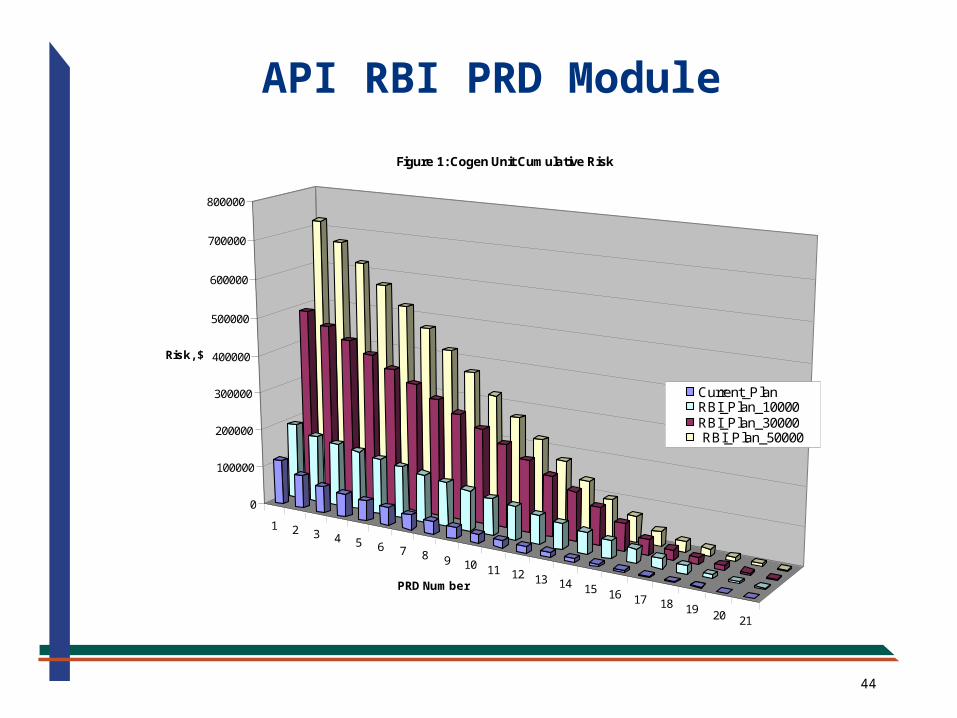
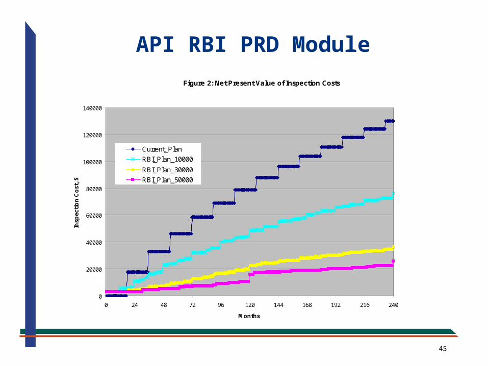
• Case Studies (Con’t.)
– COGEN Unit
• 21 PRDs
• Natural Gas, Steam, Carbon Monoxide
• Intervals set at 18 months, VERY conservative
• Client unsure of risk tolerance, ran sensitivity analysis (RT = $10K, $30K and $50K)
• RBI plan increased average interval to 86 months
• 80% reduction in inspection costs
• Significant increase in risk, based on Company’s risk tolerance
API RBI PRD Module
44
1 2 3 4 5 6 7 8 9 10 11 12 13 14 15 16 17 18 19 20 21
0
100000
200000
300000
400000
500000
600000
700000
800000
Risk, $
PRD Number
Figure 1: Cogen Unit Cumulative Risk
Current_PlanRBI_Plan_10000RBI_Plan_30000 RBI_Plan_50000
API RBI PRD Module
45
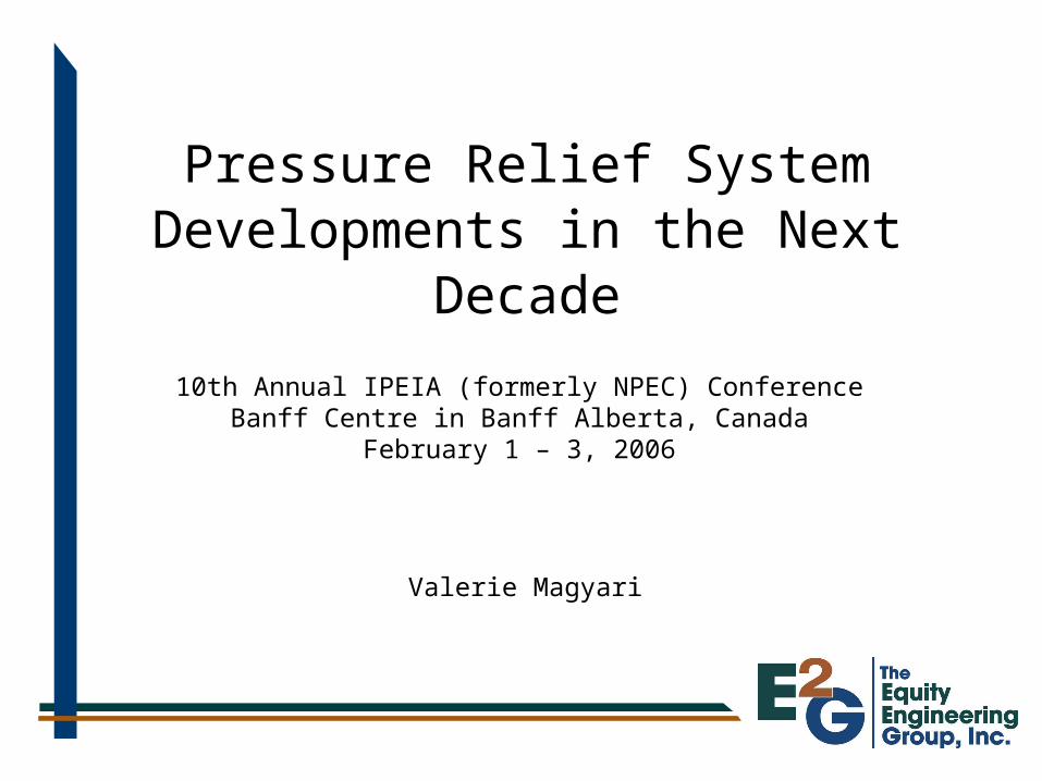
Figure 2: Net Present Value of Inspection Costs
0
20000
40000
60000
80000
100000
120000
140000
0 24 48 72 96 120 144 168 192 216 240
Months
Insp
ecti
on
Co
st, $
Current_Plan
RBI_Plan_10000
RBI_Plan_30000
RBI_Plan_50000
API RBI PRD Module
46
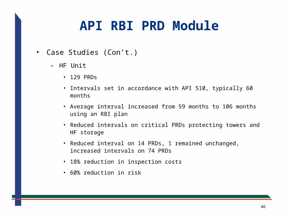
• Case Studies (Con’t.)
– HF Unit
• 129 PRDs
• Intervals set in accordance with API 510, typically 60 months
• Average interval increased from 59 months to 106 months using an RBI plan
• Reduced intervals on critical PRDs protecting towers and HF storage
• Reduced interval on 14 PRDs, 1 remained unchanged, increased intervals on 74 PRDs
• 18% reduction in inspection costs
• 60% reduction in risk
API RBI PRD Module
47
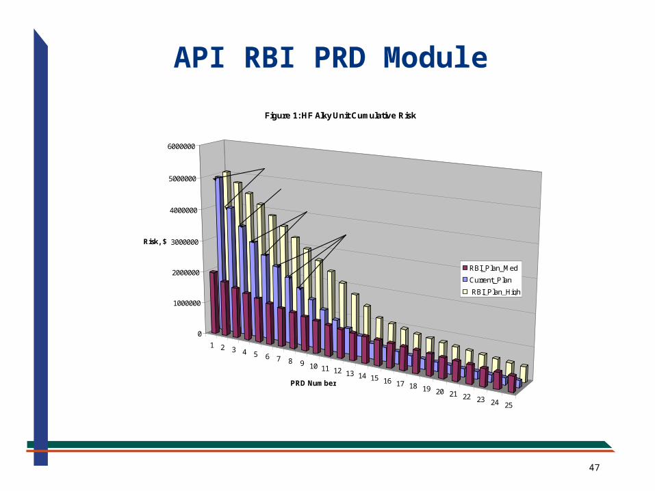
1 2 3 4 5 6 7 8 9 10 11 12 13 14 15 16 17 18 19 20 21 22 23 24 25
0
1000000
2000000
3000000
4000000
5000000
6000000
Risk, $
PRD Number
Figure 1: HF Alky Unit Cumulative Risk
RBI_Plan_Med
Current_Plan
RBI_Plan_High
28-V-10 Acid Settler PRVs
28-T-6 Depropanizer PSV
28-V-19 Acid Storage PSVs
28-T-5 Isostripper PSVs
API RBI PRD Module
48
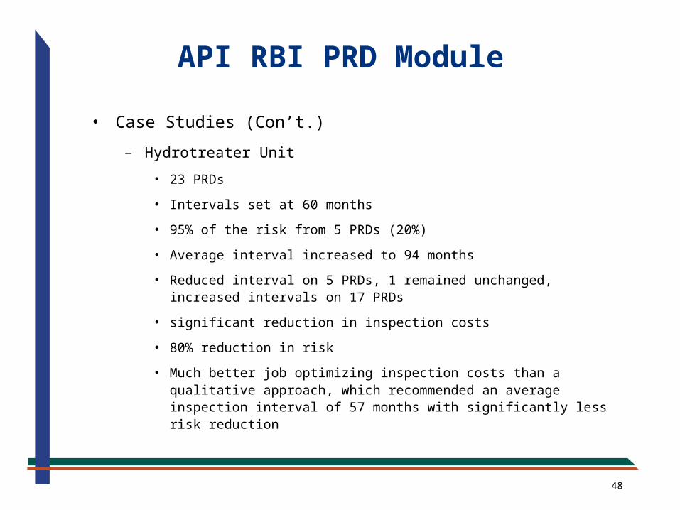
API RBI PRD Module
• Case Studies (Con’t.)
– Hydrotreater Unit
• 23 PRDs
• Intervals set at 60 months
• 95% of the risk from 5 PRDs (20%)
• Average interval increased to 94 months
• Reduced interval on 5 PRDs, 1 remained unchanged, increased intervals on 17 PRDs
• significant reduction in inspection costs
• 80% reduction in risk
• Much better job optimizing inspection costs than a qualitative approach, which recommended an average inspection interval of 57 months with significantly less risk reduction
49
12
34
56
78
910
0
500000
1000000
1500000
2000000
2500000
3000000
3500000
Risk, $
PRD Number
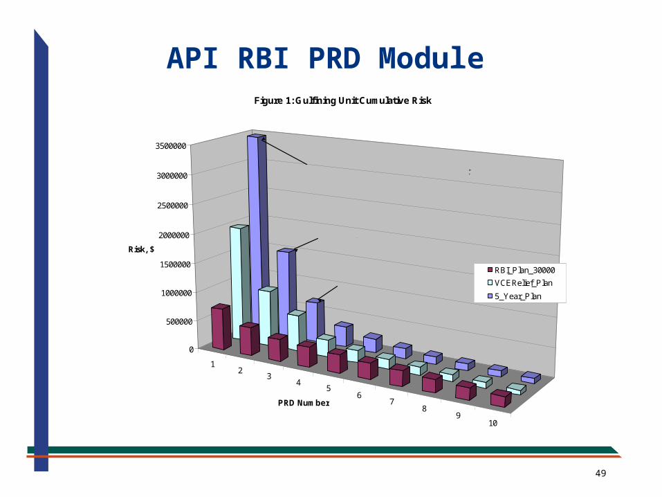
Figure 1: Gulfining Unit Cumulative Risk
RBI_Plan_30000
VCERelief_Plan
5_Year_Plan
PSV-J04
PSV-004 protectecting V-5, Stabilizer Tower
PSV-J05
API RBI PRD Module
50
Summary• Recent and proposed changes to ASME Codes and API
Standards are recognizing the use of risk principles for the design, installation, sizing, inspection and testing of pressure relieving devices and systems
• Proposed modification to UG-140 of the ASME Code will allow the user to design a pressurized system without the presence of a pressure relief device
• Recent modification to Appendix M of the ASME Code allows the user in some cases to eliminate the blocked-in scenario when isolation valves are located in the pressure relief path
• Recent modification to API 510 allows the use of RBI to set the intervals for pressure relief device inspection and testing
• These trends provide the Owner/User with operational and inspection flexibility, but requires increased responsibility

51
Valerie MagyariFluid Systems Senior Engineer
20600 Chagrin Blvd. • Suite 1200Shaker Heights, OH 44122 USA
Phone: 216-283-9519 • Fax: 216-283-6022www.equityeng.com