Embed Size (px)
Citation preview
Voltage and Reactive Power
Control by Wind Turbines
Jens Fortmann, REpower Systems SE
Berlin, October 16th 2012
2Jens Fortmann, IEEE ISGT, 16.10.2012, © REpower Systems SE
Voltage and Reactive Power Control by Wind Turbines
Starting point is the behavior of a synchronous generators
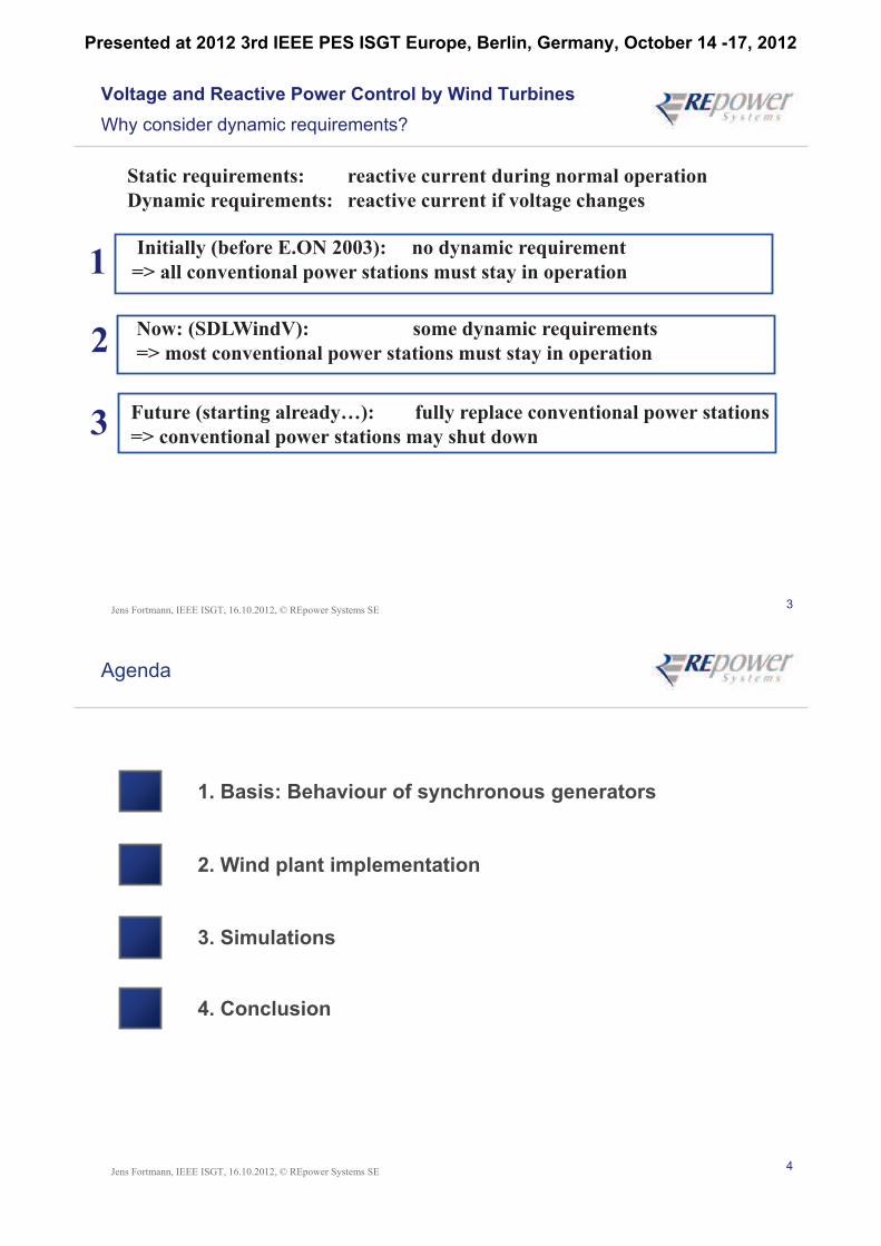
Questions for the turbine reactive power control design:
How should we operate a wind turbine
to offer the best grid support possible
How should wind turbines behave to replace conventional power stations
with no need for further grid reinforcement or grid equipment
Can we do even better
(than conventional power stations)
How do conventional power stations contribute to grid stability
?
?
1
2
3 ?
?
Presented at 2012 3rd IEEE PES ISGT Europe, Berlin, Germany, October 14 -17, 2012
3Jens Fortmann, IEEE ISGT, 16.10.2012, © REpower Systems SE
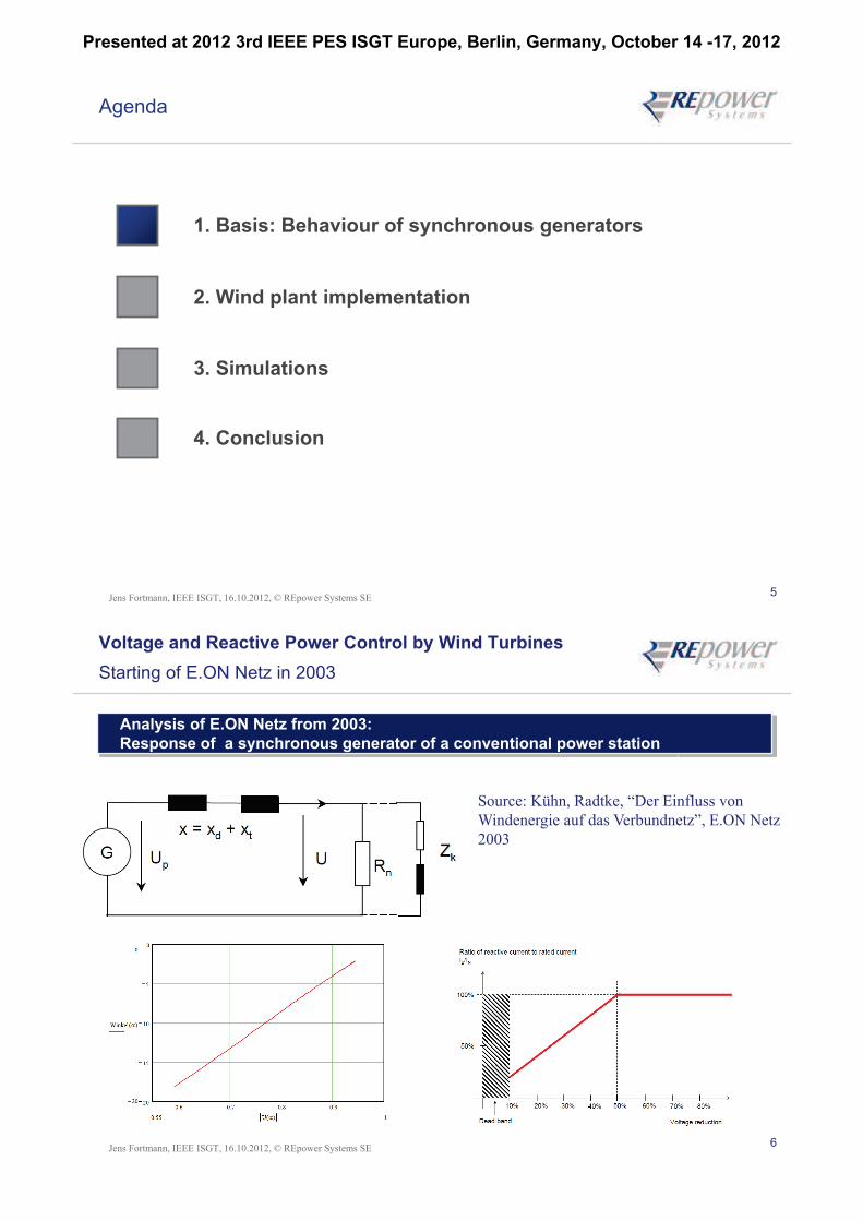
Voltage and Reactive Power Control by Wind Turbines
Why consider dynamic requirements?
Static requirements: reactive current during normal operation
Dynamic requirements: reactive current if voltage changes
Initially (before E.ON 2003): no dynamic requirement
=> all conventional power stations must stay in operation
Future (starting already…): fully replace conventional power stations
=> conventional power stations may shut down
Now: (SDLWindV): some dynamic requirements
=> most conventional power stations must stay in operation
1
2
3
4Jens Fortmann, IEEE ISGT, 16.10.2012, © REpower Systems SE
Agenda
1. Basis: Behaviour of synchronous generators
2. Wind plant implementation
3. Simulations
4. Conclusion
Presented at 2012 3rd IEEE PES ISGT Europe, Berlin, Germany, October 14 -17, 2012
5Jens Fortmann, IEEE ISGT, 16.10.2012, © REpower Systems SE
Agenda
1. Basis: Behaviour of synchronous generators
2. Wind plant implementation
3. Simulations
4. Conclusion
6Jens Fortmann, IEEE ISGT, 16.10.2012, © REpower Systems SE
Voltage and Reactive Power Control by Wind Turbines
Starting of E.ON Netz in 2003
Analysis of E.ON Netz from 2003:
Response of a synchronous generator of a conventional power station
Source: Kühn, Radtke, “Der Einfluss von
Windenergie auf das Verbundnetz”, E.ON Netz
2003
Presented at 2012 3rd IEEE PES ISGT Europe, Berlin, Germany, October 14 -17, 2012
7Jens Fortmann, IEEE ISGT, 16.10.2012, © REpower Systems SE
pv
d dj jx x
d dj jx x
qv
sv
qv
djx
d0v
q qj jx x
q qj jx x
dv
dv
qjx
sr Tr
z
HVv
Trv
ev
Setpoints field voltage /excitation controller
reactive currentgeneration (genertor)
high voltage transformer
refv HV
i
AV
R
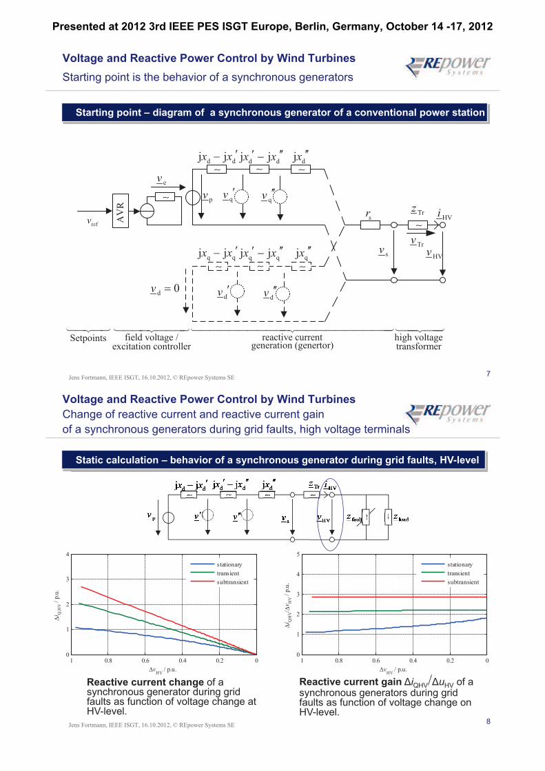
Voltage and Reactive Power Control by Wind Turbines
Starting point is the behavior of a synchronous generators
Starting point – diagram of a synchronous generator of a conventional power station
8Jens Fortmann, IEEE ISGT, 16.10.2012, © REpower Systems SE
Voltage and Reactive Power Control by Wind Turbines
Change of reactive current and reactive current gain
of a synchronous generators during grid faults, high voltage terminals
Static calculation – behavior of a synchronous generator during grid faults, HV-level
Reactive current change of a synchronous generator during grid faults as function of voltage change at HV-level.
Reactive current gain iQHV/ uHV of a synchronous generators during grid faults as function of voltage change on HV-level.
1 0.8 0.6 0.4 0.2 00
1
2
3
4
5
i QH
V/v
HV /
p.u
.
vHV
/ p.u.
stationary
transient
subtransient
1 0.8 0.6 0.4 0.2 00
1
2
3
4
vHV
/ p.u.
i Q,H
V /
p.u
.
stationary
transient
subtransient
Presented at 2012 3rd IEEE PES ISGT Europe, Berlin, Germany, October 14 -17, 2012
9Jens Fortmann, IEEE ISGT, 16.10.2012, © REpower Systems SE
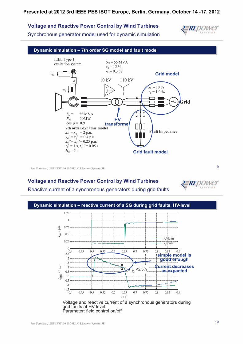
Voltage and Reactive Power Control by Wind Turbines
Synchronous generator model used for dynamic simulation
Dynamic simulation – 7th order SG model and fault model
10 kV 110 kV
xk = 10 %
rk = 1.0 %
Fault impedance
SN = 55 MVA
PN = 50MW
cos = 0.9
7th order dynamic model
xd = xq = 2 p.u.
xd’ = xq’ = 0.4 p.u.
xd’’= xq’’= 0.25 p.u.
td’ = 1 s, td’’ = 0.05 s
Hg = 5 s
vfd
ve
SN = 55 MVA
xk = 12 %
rk = 0.3 %
Grid
IEEE Type 1
excitation system
Grid fault model
Grid model
HV transformer
10Jens Fortmann, IEEE ISGT, 16.10.2012, © REpower Systems SE
Voltage and Reactive Power Control by Wind Turbines
Reactive current of a synchronous generators during grid faults
Dynamic simulation – reactive current of a SG during grid faults, HV-level
Voltage and reactive current of a synchronous generators during grid faults at HV-levelParameter: field control on/off
0.4 0.45 0.5 0.55 0.6 0.65 0.7 0.75 0.8 0.85 0.90
0.25
0.5
0.75
1
1.25
vH
V /
p.u
.
0.4 0.45 0.5 0.55 0.6 0.65 0.7 0.75 0.8 0.85 0.9-1.5
-1
-0.5
0
0.5
1
1.5
2
2.5
I QH
V /
/ p
.u.
t / s
AVR on
vf=const
IQ
<2.5%
simple model is good enough
Current decreases as expected
Presented at 2012 3rd IEEE PES ISGT Europe, Berlin, Germany, October 14 -17, 2012
11Jens Fortmann, IEEE ISGT, 16.10.2012, © REpower Systems SE
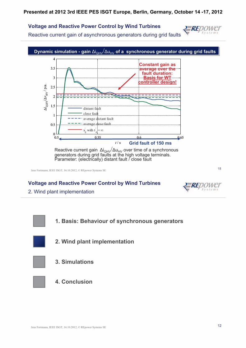
Voltage and Reactive Power Control by Wind Turbines
Reactive current gain of asynchronous generators during grid faults
Dynamic simulation - gain QHV/ HV of a synchronous generator during grid faults
Reactive current gain QHV/ HV over time of a synchronous generators during grid faults at the high voltage terminals. Parameter: (electrically) distant fault / close fault
0.5 0.55 0.6 0.650
0.5
1
1.5
2
2.5
3
3.5
4
i Q,H
V/v
HV /
p.u
.
t / s
distant fault
close fault
average distant fault
average close fault
xd
' with t
d
' =
0.5 0.55 0.6 0.650
0.5
1
1.5
2
2.5
3
3.5
4
i Q,H
V/v
HV /
p.u
.
t / s
distant fault
close fault
average distant fault
average close fault
xd
' with t
d
' =
Constant gain as average over the
fault duration:Basis for WT
controller design!
Grid fault of 150 ms
12Jens Fortmann, IEEE ISGT, 16.10.2012, © REpower Systems SE
Voltage and Reactive Power Control by Wind Turbines
2. Wind plant implementation
1. Basis: Behaviour of synchronous generators
2. Wind plant implementation
3. Simulations
4. Conclusion
Presented at 2012 3rd IEEE PES ISGT Europe, Berlin, Germany, October 14 -17, 2012
13Jens Fortmann, IEEE ISGT, 16.10.2012, © REpower Systems SE
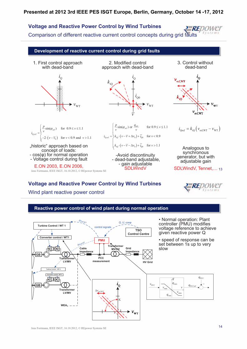
Voltage and Reactive Power Control by Wind Turbines
Comparison of different reactive current control concepts during grid faults
Development of reactive current control during grid faults
Qref iQ ref,WT WTi k v v
3. Control withoutdead-band
2. Modified control approach with dead-band
1. First control approachwith dead-band
„historic“ approach based on concept of loads:
- cos(- Voltage control during fault
E.ON 2003, E.ON 2006,
Analogous to synchronous
generator, but with adjustable gain
SDLWindV, Tennet,…
-Avoid discontinuity- dead-band adjustable,
- gain adjustableSDLWindV
Qi
WTv
refref
Q,ref iQ 0 Q0
iQ 0 Q0
sin( ) or for 0.9 1.1
for 0.9
for 1.1
qpv
v v
i k v v v i v
k v v v i v
ref
Q,ref
0
sin( ) for 0.9 1.1
2 for 0.9 and 1.1
pv
vi
v v v v
Qi
WTv
iQk
v
Q0i
14Jens Fortmann, IEEE ISGT, 16.10.2012, © REpower Systems SE
Voltage and Reactive Power Control by Wind Turbines
Wind plant reactive power control
Reactive power control of wind plant during normal operation
Transformer
LV/MV
PMU
Grid
Impedance
HV Grid
Transformer
MV/HV
Turbine Control / WT 1
Cable
Impedance
PCC
measurement
TSO
Control Centre
control signals
GB
Converter control / WT1
Transformer
LV/MV
GB
WEAn
Turbine Control / WT 2
Converter control / WT 2
Q, U, cosVref,WT
vref,WT
• Normal operation: Plant controller (PMU) modifies voltage reference to achieve given reactive power Q
• speed of response can be set between 1s up to very slow
ref,WT
K
PCCrefq
PCCq
maxq
minqmaxv
minv
q
vPCCv
Presented at 2012 3rd IEEE PES ISGT Europe, Berlin, Germany, October 14 -17, 2012
15Jens Fortmann, IEEE ISGT, 16.10.2012, © REpower Systems SE
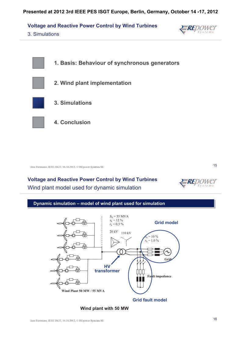
Voltage and Reactive Power Control by Wind Turbines
3. Simulations
1. Basis: Behaviour of synchronous generators
2. Wind plant implementation
3. Simulations
4. Conclusion
16Jens Fortmann, IEEE ISGT, 16.10.2012, © REpower Systems SE
Voltage and Reactive Power Control by Wind Turbines
Wind plant model used for dynamic simulation
Dynamic simulation – model of wind plant used for simulation
Wind plant with 50 MW
20 kV 110 kV
Fault impedance
Wind Plant 50 MW / 55 MVA
Grid
xk = 10 %
rk = 1.0 %
SN = 55 MVA
xk = 12 %
rk = 0.3 %
Grid fault model
Grid model
HV transformer
Presented at 2012 3rd IEEE PES ISGT Europe, Berlin, Germany, October 14 -17, 2012
17Jens Fortmann, IEEE ISGT, 16.10.2012, © REpower Systems SE
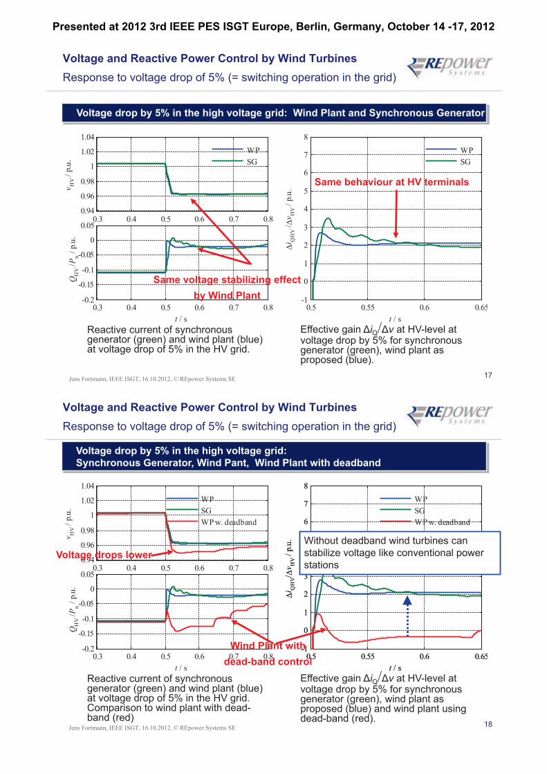
Voltage and Reactive Power Control by Wind Turbines
Response to voltage drop of 5% (= switching operation in the grid)
Voltage drop by 5% in the high voltage grid: Wind Plant and Synchronous Generator
Reactive current of synchronous generator (green) and wind plant (blue) at voltage drop of 5% in the HV grid.
Effective gain iQ/ v at HV-level at voltage drop by 5% for synchronous generator (green), wind plant as proposed (blue).
0.3 0.4 0.5 0.6 0.7 0.80.94
0.96
0.98
1
1.02
1.04
vH
V /
p.u
.
0.3 0.4 0.5 0.6 0.7 0.8-0.2
-0.15
-0.1
-0.05
0
0.05
QH
V /P
n /
p.u
.
t / s
WP
SG
0.5 0.55 0.6 0.65-1
0
1
2
3
4
5
6
7
8
i QH
V /v
HV /
p.u
.
t / s
WP
SG
Same voltage stabilizing effect
by Wind Plant
Same behaviour at HV terminals
18Jens Fortmann, IEEE ISGT, 16.10.2012, © REpower Systems SE
0.5 0.55 0.6 0.65-1
0
1
2
3
4
5
6
7
8
i QH
V/v
HV /
p.u
.
t / s
WP
SG
Voltage drop by 5% in the high voltage grid:
Synchronous Generator, Wind Pant, Wind Plant with deadband
Reactive current of synchronous generator (green) and wind plant (blue) at voltage drop of 5% in the HV grid. Comparison to wind plant with dead-band (red)
Effective gain iQ/ v at HV-level at voltage drop by 5% for synchronous generator (green), wind plant as proposed (blue) and wind plant using dead-band (red).
Voltage and Reactive Power Control by Wind Turbines
Response to voltage drop of 5% (= switching operation in the grid)
0.3 0.4 0.5 0.6 0.7 0.80.94
0.96
0.98
1
1.02
1.04
vH
V /
p.u
.
0.3 0.4 0.5 0.6 0.7 0.8-0.2
-0.15
-0.1
-0.05
0
0.05
QH
V /P
n /
p.u
.
t / s
WP
SG
WP w. deadband
0.5 0.55 0.6 0.65-1
0
1
2
3
4
5
6
7
8
i QH
V/v
HV /
p.u
.
t / s
WP
SG
WP w. deadband
Without deadband wind turbines can
stabilize voltage like conventional power
stations
Wind Plant with
dead-band control
Voltage drops lower
Presented at 2012 3rd IEEE PES ISGT Europe, Berlin, Germany, October 14 -17, 2012
19Jens Fortmann, IEEE ISGT, 16.10.2012, © REpower Systems SE
Conclusion
1. Basis: Behaviour of synchronous generators
2. Wind plant implementation
3. Simulations
4. Conclusion
20Jens Fortmann, IEEE ISGT, 16.10.2012, © REpower Systems SE
Voltage and Reactive Power Control by Wind Turbines
Conclusion: WEC reactive power control without deadband
Reactive current control equivalent to synchronous generators
Technical issues
• Reactive current control equivalent to synchronous generators
• fast response to voltage changes, slow response to setpoint changes
• reactive current proportional to voltage change
• damping of voltage changes in the grid
• no deadband
Key points
• Use of deadband risks voltage stability at very high wind penetration
• fast voltage control equivalent to synchronous generators stabilizes grid voltage
• Technology available for different wind turbine control implementations
=> Technology ready for the grids of the future
Presented at 2012 3rd IEEE PES ISGT Europe, Berlin, Germany, October 14 -17, 2012
21Jens Fortmann, IEEE ISGT, 16.10.2012, © REpower Systems SE
© REpower Systems SE
All rights reserved. No part of this document may be reproduced or transmitted in any form or by any means, electronic or mechanical,
including photography, recording, or any information storage and retrieval system, without permission from REpower Systems AG.
22Jens Fortmann, IEEE ISGT, 16.10.2012, © REpower Systems SE
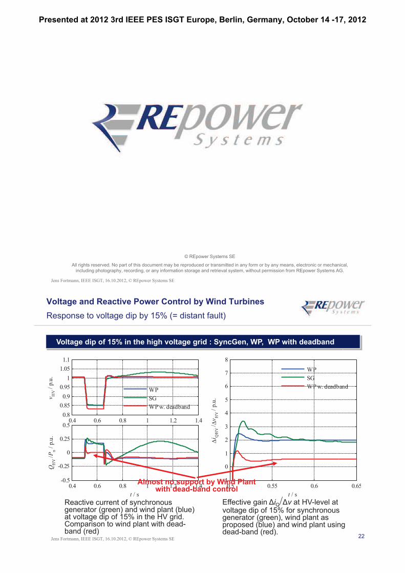
Voltage and Reactive Power Control by Wind Turbines
Response to voltage dip by 15% (= distant fault)
Voltage dip of 15% in the high voltage grid : SyncGen, WP, WP with deadband
Reactive current of synchronous generator (green) and wind plant (blue) at voltage dip of 15% in the HV grid. Comparison to wind plant with dead-band (red)
Effective gain iQ/ v at HV-level at voltage dip of 15% for synchronous generator (green), wind plant as proposed (blue) and wind plant using dead-band (red).
0.4 0.6 0.8 1 1.2 1.40.8
0.85
0.9
0.95
1
1.05
1.1
vH
V /
p.u
.
0.4 0.6 0.8 1 1.2 1.4-0.5
-0.25
0
0.25
0.5
QH
V /P
n /
p.u
.
t / s
WP
SG
WP w. deadband
0.5 0.55 0.6 0.65-1
0
1
2
3
4
5
6
7
8
i QH
V /v
HV /
p.u
.
t / s
WP
SG
WP w. deadband
Almost no support by Wind Plantwith dead-band control
Presented at 2012 3rd IEEE PES ISGT Europe, Berlin, Germany, October 14 -17, 2012
23Jens Fortmann, IEEE ISGT, 16.10.2012, © REpower Systems SE
Voltage and Reactive Power Control by Wind Turbines
Comparison of synchronous generator and wind plant using proposed control
Voltage in the high voltage grid: Synchronous Generator and Wind Plant
Voltage dip by 80% Voltage dip by 15%
0 1 2 3 40
0.250.5
0.751
1.25
v /
p.u
.
0 1 2 3 4-0.5
00.5
11.5
2
P/P
n /
p.u
.
0 1 2 3 4-1
-0.5
0
0.5
1
Q/P
n /
p.u
.
t / s
WP,HV
SG,HV
0 1 2 3 40.8
0.9
1
1.1
v /
p.u
.
0 1 2 3 40.5
0.75
1
1.25
P/P
n /
p.u
.
0 1 2 3 4-0.5
-0.25
0
0.25
0.5
Q/P
n /
p.u
.
t / s
WP,HV
SG,HV
Severe oscillations of Sync. Generator
Almost no oscillations by Wind Plant
24Jens Fortmann, IEEE ISGT, 16.10.2012, © REpower Systems SE
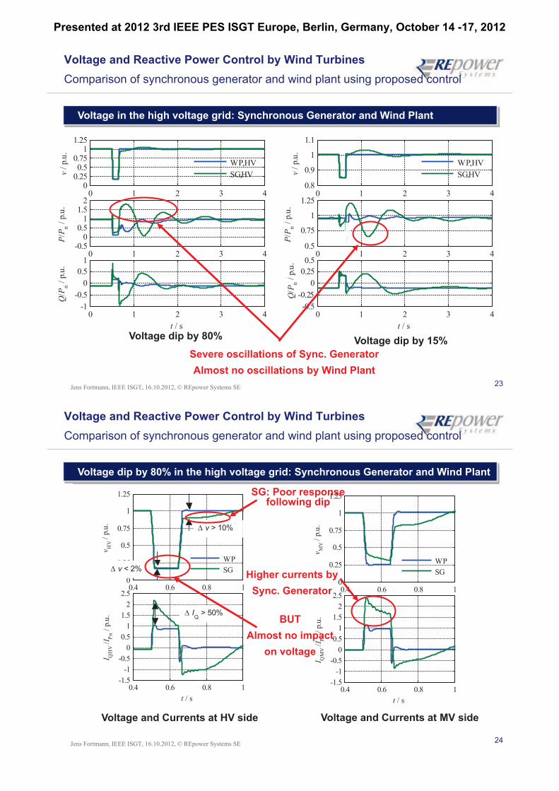
Voltage and Reactive Power Control by Wind Turbines
Comparison of synchronous generator and wind plant using proposed control
Voltage dip by 80% in the high voltage grid: Synchronous Generator and Wind Plant
Voltage and Currents at HV side Voltage and Currents at MV side
0.4 0.6 0.8 10
0.25
0.5
0.75
1
1.25
vH
V /
p.u
.
0.4 0.6 0.8 1-1.5
-1
-0.5
0
0.5
1
1.5
2
2.5
I QH
V /I P
n /
p.u
.
t / s
WP
SG
v > 10%
v < 2%
IQ > 50%
0.4 0.6 0.8 10
0.25
0.5
0.75
1
1.25
vM
V /
p.u
.
0.4 0.6 0.8 1-1.5
-1
-0.5
0
0.5
1
1.5
2
2.5
I QM
V /I P
n /
p.u
.
t / s
WP
SGHigher currents by
Sync. Generator
BUT
Almost no impact
on voltage
SG: Poor response following dip
Presented at 2012 3rd IEEE PES ISGT Europe, Berlin, Germany, October 14 -17, 2012
25Jens Fortmann, IEEE ISGT, 16.10.2012, © REpower Systems SE
pv
d dj jx x
d dj jx x
qv
sv
qv
djx
d0v
q qj jx x
q qj jx x
dv
dv
qjx
sr Tr
z
HVv
Trv
ev
Setpoints field voltage /excitation controller
reactive currentgeneration (genertor)
high voltage transformer
refv HV
i
AV
R
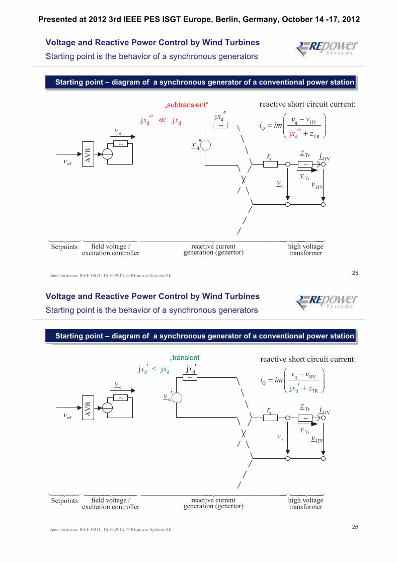
Voltage and Reactive Power Control by Wind Turbines
Starting point is the behavior of a synchronous generators
Starting point – diagram of a synchronous generator of a conventional power station
„subtransient“
qv
djx
d dj jx x q HV
Q
d TR
reactive short circuit current
j
:
v vi im
zx
26Jens Fortmann, IEEE ISGT, 16.10.2012, © REpower Systems SE
pv
d dj jx x
d dj jx x
qv
sv
qv
djx
d0v
q qj jx x
q qj jx x
dv
dv
qjx
sr Tr
z
HVv
Trv
ev
Setpoints field voltage /excitation controller
reactive currentgeneration (genertor)
high voltage transformer
refv HV
i
AV
R
„subtransient“
qv
djx
„transient“
djx
qv
d dj < jx x
Voltage and Reactive Power Control by Wind Turbines
Starting point is the behavior of a synchronous generators
Starting point – diagram of a synchronous generator of a conventional power station
q HV
Q
d TR
reactive short circuit current
j
:
v vi im
zx
Presented at 2012 3rd IEEE PES ISGT Europe, Berlin, Germany, October 14 -17, 2012
27Jens Fortmann, IEEE ISGT, 16.10.2012, © REpower Systems SE
pv
d dj jx x
d dj jx x
qv
sv
qv
djx
d0v
q qj jx x
q qj jx x
dv
dv
qjx
sr Tr
z
HVv
Trv
ev
Setpoints field voltage /excitation controller
reactive currentgeneration (genertor)
high voltage transformer
refv HV
i
AV
R
„subtransient“
qv
djx
„transient“
djx
qv
d dj < jx x
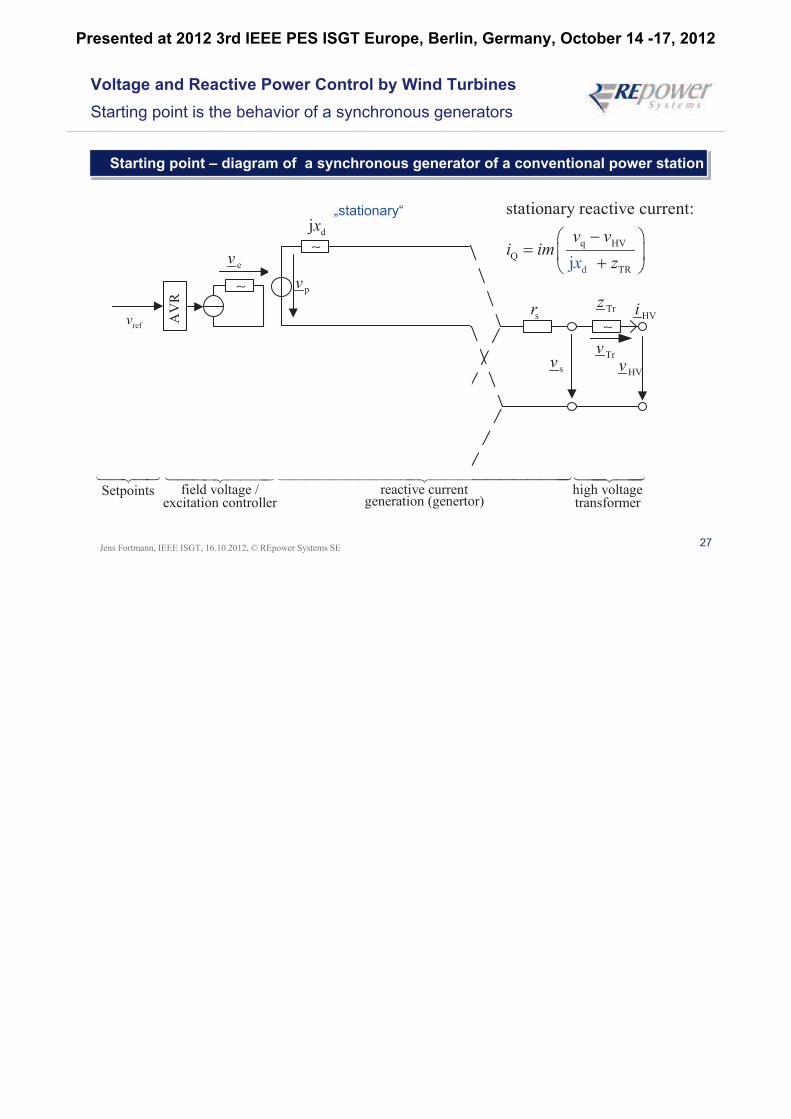
„stationary“
pv
djx
Voltage and Reactive Power Control by Wind Turbines
Starting point is the behavior of a synchronous generators
Starting point – diagram of a synchronous generator of a conventional power station
d
q HV
Q
TR
stationary reactive current
j
:
v vi im
zx
Presented at 2012 3rd IEEE PES ISGT Europe, Berlin, Germany, October 14 -17, 2012