Embed Size (px)
Citation preview
Candia FS Owner’s Manual03/00
PrefacePage 1
This manual will acquaint you with the use and maintenance of your new Four Winns® boat. This manual alsoprovides special information critical to the safety of the passengers, and longevity of the equipment. Theinformation on the following page lists the conventions used to increase the visibility of these important mes-sages. Also included in your owner’s packet is the “Boating Basics, A Guide to Responsible Boating”. Thispublication covers all the boating basics and should be read along with your Four Winns® Owners Manualbefore operating your boat. Review this information in detail.
Four Winns® continually strives to improve its products. Unit specifications, including standard and optionalequipment are constantly being modified. Equipment availability is also subject to change. The mostcurrent and accurate information available at the time of publication is included in this manual. Somevariation in equipment, description, location, and details can result.
The information in this manual focuses upon the equipment designed and manufactured by Four Winns® onspecific models. When appropriate, please utilize the information pertinent to your specific boat model.
Equipment such as engines, and other accessories are manufactured by others. The information provided inthis manual is intended to be used in conjunction with the information provided by the manufacturers of thisequipment. All information available at the time of manufacture has been included with your owner’s packet.
Read this entire manual carefully before operating your new boat. Many instructions may require directperformance of the activity to fully understand the correct method. If you choose to read this manual at home,remember to take it to the boat with you.
Your Four Winns® dealer knows your boat best and is interested in your complete satisfaction. Return to himfor service or other assistance. If you find it necessary to contact Four Winns® directly, please refer to theaddress information listed below. Be sure to include the boat model, serial number, your daytime telephonenumber, and specifics of the information desired.
This manual has been specifically developed for the Candia Funship 214, 234, and 254 models. Pleaserecord the model and serial number information below.
Model Serial Number
________________________ __________________________
This manual should be considered part of the boat. Should you sell the boat, pass this manual on to the newowner. Take special care of this manual. Certain information in this manual may not be available in a replace-ment manual.
Thank you for joining the Four Winns® family. We appreciate your purchase and welcome the opportunity todemonstrate our commitment to you.
Four Winns® Customer Service Department925 Frisbie Street
Cadillac, Michigan 49601231-775-1343 (Phone)
231-779-2345 (FAX)E-Mail Address: [email protected]
© FourWinns L.L.C. 2000. All Rights Reserved.
PREFACE
Candia FS Owner’s Manual03/00
PrefacePage 2
SAFETY WARNINGSThis manual contains instructions critical to the safety of those aboard or the longevity of the equipment. Payclose attention to all safety warnings. The following safety warnings and instructions are used throughoutthe manual and at selected locations on your boat.
This safety symbol and this signal word indicate an imminently hazardous situation which if notavoided, WILL result in death or serious injury.
This safety symbol and this signal word indicate a potentially hazardous situation which, if notavoided CAN result in severe injury or death.
This safety symbol and this signal word indicate a potentially hazardous situation which, if notavoided MAY result in minor or moderate personal injury or property damage. It may also be usedto alert against unsafe practices.
NOTICEThis is used to notify people of installation, operation, or maintenance information which is importantbut not hazard-related.
YOU are responsible for your own safety, as well as the safety of your passengers and fellow boaters.You should fully understand and become familiar with the operating procedures and safety precau-tions in this manual and any other information in the Owners Packet before you launch the boat.Always operate your boat with consideration, courtesy, and common sense.
The warnings in this manual do not and can not address every conceivable situation. Always use commonsense!
The following page illustrates the locations of various warning labels, capacity label and other stickers onyour Four Winns® boat.
Candia FS Owner’s Manual03/00
PrefacePage 3
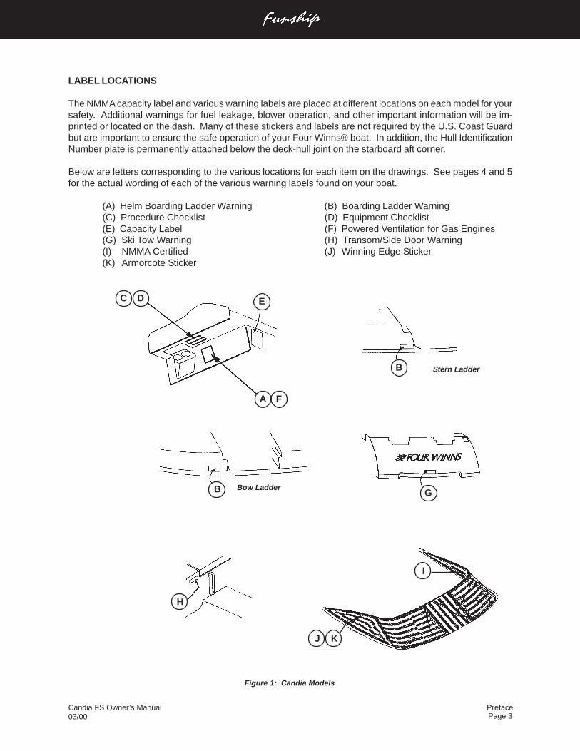
LABEL LOCATIONS
The NMMA capacity label and various warning labels are placed at different locations on each model for yoursafety. Additional warnings for fuel leakage, blower operation, and other important information will be im-printed or located on the dash. Many of these stickers and labels are not required by the U.S. Coast Guardbut are important to ensure the safe operation of your Four Winns® boat. In addition, the Hull IdentificationNumber plate is permanently attached below the deck-hull joint on the starboard aft corner.
Below are letters corresponding to the various locations for each item on the drawings. See pages 4 and 5for the actual wording of each of the various warning labels found on your boat.
(A) Helm Boarding Ladder Warning (B) Boarding Ladder Warning(C) Procedure Checklist (D) Equipment Checklist(E) Capacity Label (F) Powered Ventilation for Gas Engines(G) Ski Tow Warning (H) Transom/Side Door Warning(I) NMMA Certified (J) Winning Edge Sticker(K) Armorcote Sticker
Figure 1: Candia Models
C D
J K
I
G
H
B
B Stern Ladder
Bow Ladder
E
A F
Candia FS Owner’s Manual03/00
PrefacePage 4
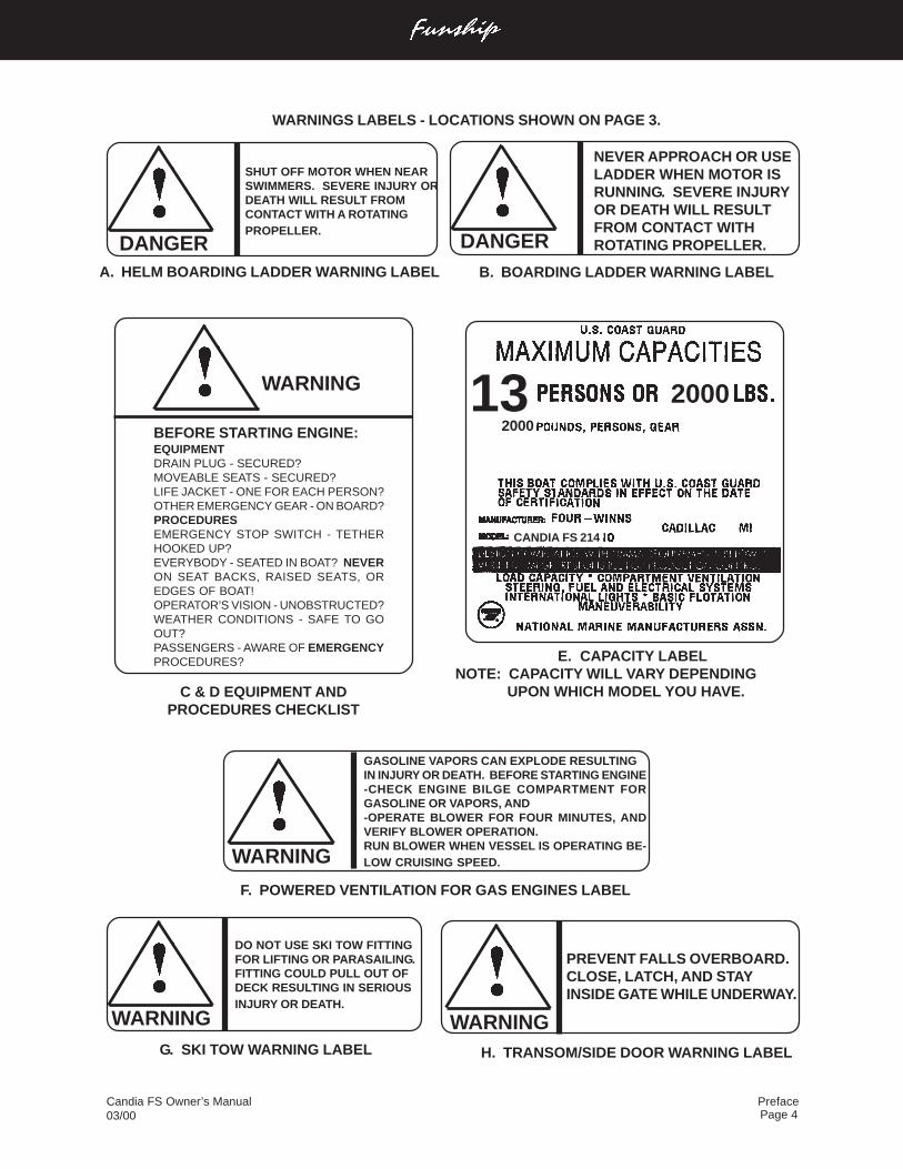
WARNING
GASOLINE VAPORS CAN EXPLODE RESULTINGIN INJURY OR DEATH. BEFORE STARTING ENGINE-CHECK ENGINE BILGE COMPARTMENT FORGASOLINE OR VAPORS, AND-OPERATE BLOWER FOR FOUR MINUTES, ANDVERIFY BLOWER OPERATION.RUN BLOWER WHEN VESSEL IS OPERATING BE-LOW CRUISING SPEED.
F. POWERED VENTILATION FOR GAS ENGINES LABEL
E. CAPACITY LABEL NOTE: CAPACITY WILL VARY DEPENDING
UPON WHICH MODEL YOU HAVE.
WARNING
BEFORE STARTING ENGINE:EQUIPMENTDRAIN PLUG - SECURED?MOVEABLE SEATS - SECURED?LIFE JACKET - ONE FOR EACH PERSON?OTHER EMERGENCY GEAR - ON BOARD?PROCEDURESEMERGENCY STOP SWITCH - TETHERHOOKED UP?EVERYBODY - SEATED IN BOAT? NEVERON SEAT BACKS, RAISED SEATS, OREDGES OF BOAT!OPERATOR’S VISION - UNOBSTRUCTED?WEATHER CONDITIONS - SAFE TO GOOUT?PASSENGERS - AWARE OF EMERGENCYPROCEDURES?
C & D EQUIPMENT ANDPROCEDURES CHECKLIST
WARNING
DO NOT USE SKI TOW FITTINGFOR LIFTING OR PARASAILING.FITTING COULD PULL OUT OFDECK RESULTING IN SERIOUSINJURY OR DEATH.
G. SKI TOW WARNING LABEL
CANDIA FS 214
2000132000
A. HELM BOARDING LADDER WARNING LABEL
DANGER
SHUT OFF MOTOR WHEN NEARSWIMMERS. SEVERE INJURY ORDEATH WILL RESULT FROMCONTACT WITH A ROTATINGPROPELLER.
DANGER
NEVER APPROACH OR USELADDER WHEN MOTOR ISRUNNING. SEVERE INJURYOR DEATH WILL RESULTFROM CONTACT WITHROTATING PROPELLER.
B. BOARDING LADDER WARNING LABEL
WARNINGS LABELS - LOCATIONS SHOWN ON PAGE 3.
H. TRANSOM/SIDE DOOR WARNING LABEL
WARNING
PREVENT FALLS OVERBOARD.CLOSE, LATCH, AND STAYINSIDE GATE WHILE UNDERWAY.
Candia FS Owner’s Manual03/00
PrefacePage 5
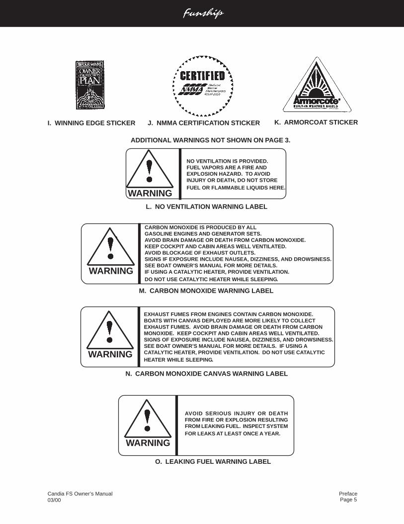
WARNING
NO VENTILATION IS PROVIDED.FUEL VAPORS ARE A FIRE ANDEXPLOSION HAZARD. TO AVOIDINJURY OR DEATH, DO NOT STOREFUEL OR FLAMMABLE LIQUIDS HERE.
L. NO VENTILATION WARNING LABEL
WARNING
CARBON MONOXIDE IS PRODUCED BY ALLGASOLINE ENGINES AND GENERATOR SETS.AVOID BRAIN DAMAGE OR DEATH FROM CARBON MONOXIDE.KEEP COCKPIT AND CABIN AREAS WELL VENTILATED.AVOID BLOCKAGE OF EXHAUST OUTLETS.SIGNS IF EXPOSURE INCLUDE NAUSEA, DIZZINESS, AND DROWSINESS.SEE BOAT OWNER’S MANUAL FOR MORE DETAILS.IF USING A CATALYTIC HEATER, PROVIDE VENTILATION.DO NOT USE CATALYTIC HEATER WHILE SLEEPING.
M. CARBON MONOXIDE WARNING LABEL
WARNING
EXHAUST FUMES FROM ENGINES CONTAIN CARBON MONOXIDE.BOATS WITH CANVAS DEPLOYED ARE MORE LIKELY TO COLLECTEXHAUST FUMES. AVOID BRAIN DAMAGE OR DEATH FROM CARBONMONOXIDE. KEEP COCKPIT AND CABIN AREAS WELL VENTILATED.SIGNS OF EXPOSURE INCLUDE NAUSEA, DIZZINESS, AND DROWSINESS.SEE BOAT OWNER’S MANUAL FOR MORE DETAILS. IF USING ACATALYTIC HEATER, PROVIDE VENTILATION. DO NOT USE CATALYTICHEATER WHILE SLEEPING.
N. CARBON MONOXIDE CANVAS WARNING LABEL
ADDITIONAL WARNINGS NOT SHOWN ON PAGE 3.
WARNING
AVOID SERIOUS INJURY OR DEATHFROM FIRE OR EXPLOSION RESULTINGFROM LEAKING FUEL. INSPECT SYSTEMFOR LEAKS AT LEAST ONCE A YEAR.
O. LEAKING FUEL WARNING LABEL
K. ARMORCOAT STICKERI. WINNING EDGE STICKER J. NMMA CERTIFICATION STICKER
Candia FS Owner’s Manual03/00
PrefacePage 6
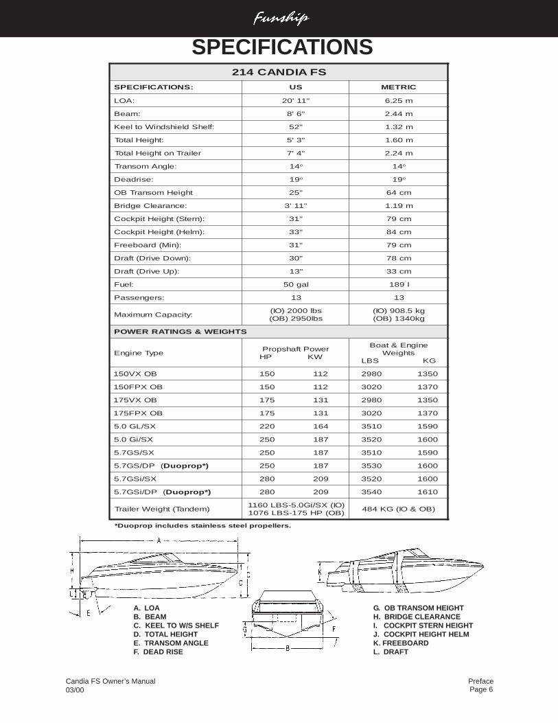
SFAIDNAC412
:SNOITACIFICEPS SU CIRTEM
:AOL "11'02 m52.6
:maeB "6'8 m44.2
:flehSdleihsdniWotleeK "25 m23.1
:thgieHlatoT "3'5 m06.1
reliarTnothgieHlatoT "4'7 m42.2
:elgnAmosnarT 41 o 41 o
:esirdaeD 91 o 91 o
thgieHmosnarTBO "52 mc46
:ecnaraelCegdirB "11'3 m91.1
:)nretS(thgieHtipkcoC "13 mc97
:)mleH(thgieHtipkcoC "33 mc48
:)niM(draobeerF "13 mc97
:)nwoDevirD(tfarD "03 mc87
:)pUevirD(tfarD "31 mc33
:leuF lag05 l981
:sregnessaP 31 31
:yticapaCmumixaMsbl0002)OI(sbl0592)BO(
gk5.809)OI(gk0431)BO(
STHGIEW&SGNITARREWOP
epyTenignErewoPtfahsporP
WKPH
enignE&taoBsthgieW
GKSBL
BOXV051 211051 05310892
BOXPF051 211051 07310203
BOXV571 131571 05310892
BOXPF571 131571 07310203
XS/LG0.5 461022 09510153
XS/iG0.5 781052 00610253
XS/SG7.5 781052 09510153
(PD/SG7.5 )*porpouD 781052 00610353
XS/iSG7.5 902082 00610253
(PD/iSG7.5 )*porpouD 902082 01610453
)mednaT(thgieWreliarT)OI(XS/iG0.5-SBL0611)BO(PH571-SBL6701
)BO&OI(GK484
.srelleporpleetssselniatssedulcniporpouD*
A. LOAB. BEAMC. KEEL TO W/S SHELFD. TOTAL HEIGHTE. TRANSOM ANGLEF. DEAD RISE
G. OB TRANSOM HEIGHTH. BRIDGE CLEARANCEI. COCKPIT STERN HEIGHTJ. COCKPIT HEIGHT HELMK. FREEBOARDL. DRAFT
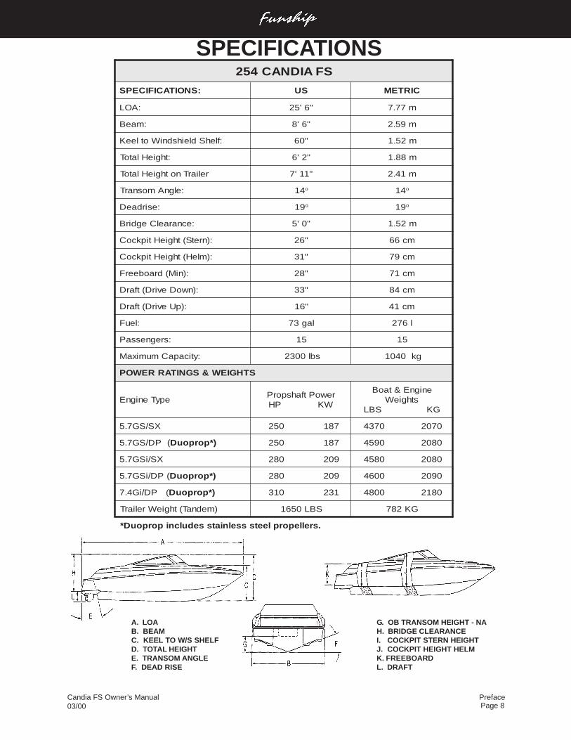
SPECIFICATIONS
Candia FS Owner’s Manual03/00
PrefacePage 7
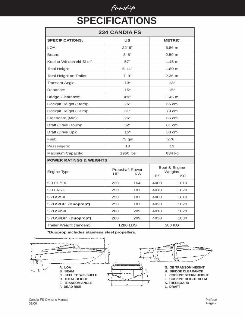
A. LOAB. BEAMC. KEEL TO W/S SHELFD. TOTAL HEIGHTE. TRANSOM ANGLEF. DEAD RISE
G. OB TRANSOM HEIGHTH. BRIDGE CLEARANCEI. COCKPIT STERN HEIGHTJ. COCKPIT HEIGHT HELMK. FREEBOARDL. DRAFT
SPECIFICATIONSSFAIDNAC432
:SNOITACIFICEPS SU CIRTEM
:AOL "6'22 m68.6
:maeB "6'8 m95.2
:flehSdleihsdniWotleeK "75 m54.1
:thgieHlatoT "11'5 m08.1
reliarTnothgieHlatoT "9'7 m63.2
:elgnAmosnarT 31 o 31 o
:esirdaeD 51 o 51 o
:ecnaraelCegdirB "9'4 m54.1
:)nretS(thgieHtipkcoC "62 mc66
:)mleH(thgieHtipkcoC "13 mc97
:)niM(draobeerF "62 mc66
:)nwoDevirD(tfarD "23 mc18
:)pUevirD(tfarD "51 mc83
:leuF lag37 l672
:sregnessaP 31 31
:yticapaCmumixaM sbl0591 gk488
STHGIEW&SGNITARREWOP
epyTenignErewoPtfahsporP
WKPH
enignE&taoBsthgieW
GKSBL
XS/LG0.5 461022 01810004
XS/iG0.5 781052 02810104
XS/SG7.5 781052 01810004
(PD/SG7.5 )*porpouD 781052 02810204
XS/iSG7.5 902082 02810104
(PD/iSG7.5 )*porpouD 902082 03810304
)mednaT(thgieWreliarT SBL0821 GK085
.srelleporpleetssselniatssedulcniporpouD*
Candia FS Owner’s Manual03/00
PrefacePage 8
A. LOAB. BEAMC. KEEL TO W/S SHELFD. TOTAL HEIGHTE. TRANSOM ANGLEF. DEAD RISE
G. OB TRANSOM HEIGHT - NAH. BRIDGE CLEARANCEI. COCKPIT STERN HEIGHTJ. COCKPIT HEIGHT HELMK. FREEBOARDL. DRAFT
SPECIFICATIONSSFAIDNAC452
:SNOITACIFICEPS SU CIRTEM
:AOL "6'52 m77.7
:maeB "6'8 m95.2
:flehSdleihsdniWotleeK "06 m25.1
:thgieHlatoT "2'6 m88.1
reliarTnothgieHlatoT "11'7 m14.2
:elgnAmosnarT 41 o 41 o
:esirdaeD 91 o 91 o
:ecnaraelCegdirB "0'5 m25.1
:)nretS(thgieHtipkcoC "62 mc66
:)mleH(thgieHtipkcoC "13 mc97
:)niM(draobeerF "82 mc17
:)nwoDevirD(tfarD "33 mc48
:)pUevirD(tfarD "61 mc14
:leuF lag37 l672
:sregnessaP 51 51
:yticapaCmumixaM sbl0032 gk0401
STHGIEW&SGNITARREWOP
epyTenignErewoPtfahsporP
WKPH
enignE&taoBsthgieW
GKSBL
XS/SG7.5 781052 07020734
(PD/SG7.5 )*porpouD 781052 08020954
XS/iSG7.5 902082 08020854
(PD/iSG7.5 )*porpouD 902082 09020064
(PD/iG4.7 )*porpouD 132013 08120084
)mednaT(thgieWreliarT SBL0561 GK287
.srelleporpleetssselniatssedulcniporpouD*
Page 1Table of ContentsCandia FS Owner’s Manual
03/00
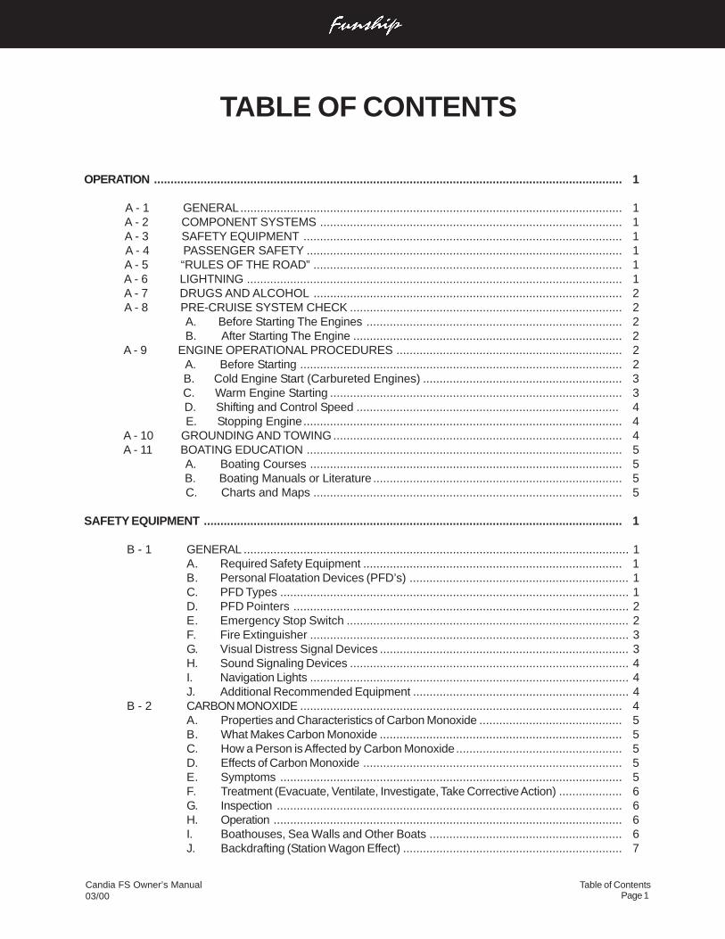
OPERATION ............................................................................................................................................. 1
A - 1 GENERAL................................................................................................................... 1 A - 2 COMPONENT SYSTEMS ........................................................................................... 1 A - 3 SAFETY EQUIPMENT ................................................................................................ 1 A - 4 PASSENGER SAFETY ............................................................................................... 1 A - 5 “RULES OF THE ROAD” ............................................................................................. 1 A - 6 LIGHTNING ................................................................................................................. 1 A - 7 DRUGS AND ALCOHOL ............................................................................................. 2 A - 8 PRE-CRUISE SYSTEM CHECK .................................................................................. 2
A. Before Starting The Engines ............................................................................. 2B. After Starting The Engine ................................................................................. 2
A - 9 ENGINE OPERATIONAL PROCEDURES .................................................................... 2 A. Before Starting ................................................................................................. 2 B. Cold Engine Start (Carbureted Engines) ............................................................ 3
C. Warm Engine Starting ........................................................................................ 3 D. Shifting and Control Speed ............................................................................... 4 E. Stopping Engine................................................................................................ 4
A - 10 GROUNDING AND TOWING ....................................................................................... 4 A - 11 BOATING EDUCATION ............................................................................................... 5
A. Boating Courses .............................................................................................. 5 B. Boating Manuals or Literature ........................................................................... 5 C. Charts and Maps ............................................................................................. 5
SAFETY EQUIPMENT .............................................................................................................................. 1
B - 1 GENERAL .................................................................................................................... 1A. Required Safety Equipment .............................................................................. 1B. Personal Floatation Devices (PFD’s) .................................................................. 1C. PFD Types ......................................................................................................... 1D. PFD Pointers ..................................................................................................... 2E. Emergency Stop Switch ..................................................................................... 2F. Fire Extinguisher ................................................................................................ 3G. Visual Distress Signal Devices ........................................................................... 3H. Sound Signaling Devices .................................................................................... 4I. Navigation Lights ................................................................................................ 4J. Additional Recommended Equipment ................................................................. 4
B - 2 CARBON MONOXIDE ................................................................................................. 4A. Properties and Characteristics of Carbon Monoxide ........................................... 5B. What Makes Carbon Monoxide ......................................................................... 5C. How a Person is Affected by Carbon Monoxide.................................................. 5D. Effects of Carbon Monoxide .............................................................................. 5E. Symptoms ....................................................................................................... 5F. Treatment (Evacuate, Ventilate, Investigate, Take Corrective Action) ................... 6G. Inspection ........................................................................................................ 6H. Operation ......................................................................................................... 6I. Boathouses, Sea Walls and Other Boats .......................................................... 6J. Backdrafting (Station Wagon Effect) .................................................................. 7
TABLE OF CONTENTS
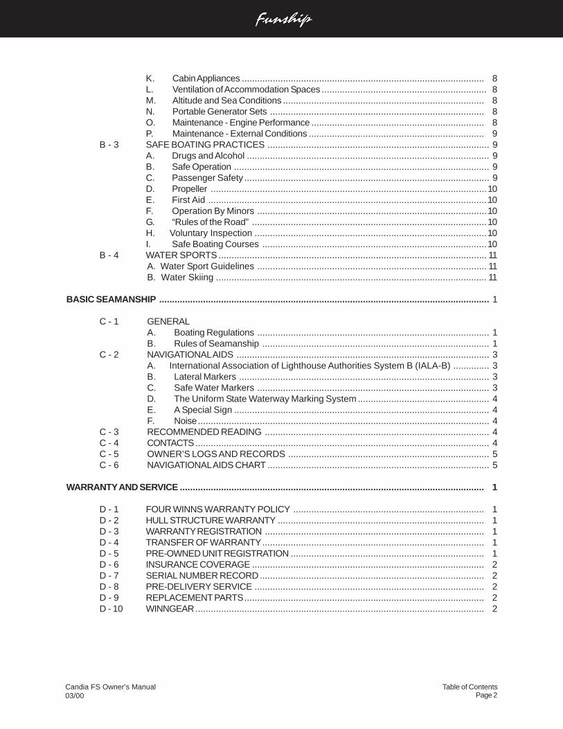
Table of ContentsPage 2
Candia FS Owner’s Manual03/00
K. Cabin Appliances .............................................................................................. 8L. Ventilation of Accommodation Spaces ................................................................ 8M. Altitude and Sea Conditions .............................................................................. 8N. Portable Generator Sets ................................................................................... 8O. Maintenance - Engine Performance ................................................................... 8P. Maintenance - External Conditions .................................................................... 9
B - 3 SAFE BOATING PRACTICES ...................................................................................... 9A. Drugs and Alcohol .............................................................................................. 9B. Safe Operation ................................................................................................... 9C. Passenger Safety ............................................................................................... 9D. Propeller ...........................................................................................................10E. First Aid ............................................................................................................10F. Operation By Minors .........................................................................................10G. “Rules of the Road” ...........................................................................................10H. Voluntary Inspection ..........................................................................................10I. Safe Boating Courses .......................................................................................10
B - 4 WATER SPORTS ........................................................................................................ 11A. Water Sport Guidelines ......................................................................................... 11B. Water Skiing ......................................................................................................... 11
BASIC SEAMANSHIP ................................................................................................................................ 1
C - 1 GENERALA. Boating Regulations .......................................................................................... 1B. Rules of Seamanship ........................................................................................ 1
C - 2 NAVIGATIONAL AIDS .................................................................................................. 3A. International Association of Lighthouse Authorities System B (IALA-B) .............. 3B. Lateral Markers ................................................................................................. 3C. Safe Water Markers .......................................................................................... 3D. The Uniform State Waterway Marking System ................................................... 4E. A Special Sign ................................................................................................... 4F. Noise................................................................................................................. 4
C - 3 RECOMMENDED READING ....................................................................................... 4C - 4 CONTACTS.................................................................................................................. 4C - 5 OWNER’S LOGS AND RECORDS .............................................................................. 5C - 6 NAVIGATIONAL AIDS CHART ...................................................................................... 5
WARRANTY AND SERVICE ...................................................................................................................... 1
D - 1 FOUR WINNS WARRANTY POLICY .......................................................................... 1D - 2 HULL STRUCTURE WARRANTY ................................................................................ 1D - 3 WARRANTY REGISTRATION ..................................................................................... 1D - 4 TRANSFER OF WARRANTY...................................................................................... 1D - 5 PRE-OWNED UNIT REGISTRATION ........................................................................... 1D - 6 INSURANCE COVERAGE .......................................................................................... 2D - 7 SERIAL NUMBER RECORD....................................................................................... 2D - 8 PRE-DELIVERY SERVICE ......................................................................................... 2D - 9 REPLACEMENT PARTS............................................................................................. 2D - 10 WINNGEAR................................................................................................................ 2
Page 3Table of ContentsCandia FS Owner’s Manual
03/00
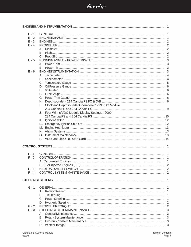
ENGINES AND INSTRUMENTATION......................................................................................................... 1
E - 1 GENERAL.............................................................................................................................. 1E - 2 ENGINE EXHAUST ................................................................................................................ 1E - 3 ENGINES............................................................................................................................... 2E - 4 PROPELLERS ....................................................................................................................... 2
A. Diameter .......................................................................................................................... 2B. Pitch ................................................................................................................................ 2C. Prop Slip ......................................................................................................................... 2
E - 5 RUNNING ANGLE & POWER TRIM/TILT................................................................................. 3A. Power Trim ...................................................................................................................... 3B. Power Tilt ........................................................................................................................ 3
E - 6 ENGINE INSTRUMENTATION ................................................................................................. 3A. Tachometer ...................................................................................................................... 4B. Speedometer ................................................................................................................... 4C. Temperature Gauge .......................................................................................................... 5D. Oil Pressure Gauge ......................................................................................................... 6E. Voltmeter ......................................................................................................................... 6F. Fuel Gauge ...................................................................................................................... 6G. Power Trim Gauge ........................................................................................................... 6H. Depthsounder - 214 Candia FS I/O & O/B ....................................................................... 6I. Clock and Depthsounder Operation - 1999 VDO Module
234 Candia FS and 254 Candia FS .................................................................................. 9J. Four Winns/VDO Module Display Settings - 2000
234 Candia FS and 254 Candia FS ...................................................................................10K. Ignition Switch ............................................................................................................... 12L.. Emergency Ignition Shut-Off ............................................................................................ 12M. Engine Hour Meter ......................................................................................................... 13N. Alarm Systems .............................................................................................................. 13O. Instrument Maintenance ................................................................................................. 13P. VDO Module Quick Start Card ..........................................................................................14
CONTROL SYSTEMS ............................................................................................................................... 1
F - 1 GENERAL.............................................................................................................................. 1F - 2 CONTROL OPERATION ......................................................................................................... 1
A. Carbureted Engines .......................................................................................................... 1B. Fuel Injected Engines (EFI) ............................................................................................... 2
F - 3 NEUTRAL SAFETY SWITCH .................................................................................................. 2F - 4 CONTROL SYSTEM MAINTENANCE ..................................................................................... 2
STEERING SYSTEMS............................................................................................................................... 1
G - 1 GENERAL.............................................................................................................................. 1A. Rotary Steering ................................................................................................................ 1B. Tilt Steering ...................................................................................................................... 1C. Power Steering ................................................................................................................. 1D. Hydraulic Steering ............................................................................................................ 2
G - 2 PROPELLER TORQUE .......................................................................................................... 2G - 3 STEERING SYSTEM MAINTENANCE .................................................................................... 3
A. General Maintenance ....................................................................................................... 3B. Rotary System Maintenance ............................................................................................ 3C. Hydraulic System Maintenance ........................................................................................ 3D. Winter Storage ................................................................................................................. 3
Table of ContentsPage 4
Candia FS Owner’s Manual03/00
ELECTRICAL SYSTEMS........................................................................................................................... 1
H - 1 GENERAL.............................................................................................................................. 1H - 2 BATTERY SYSTEM ............................................................................................................... 1
A. Single Battery System ..................................................................................................... 1H - 3 12 VOLT ELECTRICAL EQUIPMENT ...................................................................................... 1
A. Helm Equipment .............................................................................................................. 1B. Installation of Additional 12 Volt Equipment ....................................................................... 2C. Interior Equipment ............................................................................................................ 2
H - 4 ELECTRICAL SYSTEM MAINTENANCE................................................................................. 2A. Battery Maintenance ........................................................................................................ 2B. Electrical Wiring Maintenance .......................................................................................... 3
H - 5 STRAY CURRENT CORROSION ............................................................................................ 4A. General ............................................................................................................................ 4B. Galvanic Corrosion ........................................................................................................... 4C. Corrosion Prevention ........................................................................................................ 4
FUEL SYSTEMS ....................................................................................................................................... 1
I - 1 GASOLINE FUEL SYSTEMS ................................................................................................. 1A. System Testing ................................................................................................................ 1B. Fuel Fills ......................................................................................................................... 1C. Anti-Syphon Valves .......................................................................................................... 2D. Fuel Gauge ...................................................................................................................... 2E. Fuel Senders ................................................................................................................... 2F. Fuel Filters ...................................................................................................................... 3G. Use and Maintenance ...................................................................................................... 3
I - 2 FUEL STANDARDS................................................................................................................ 3A. Problems With Alcohol in Gasoline ................................................................................... 3B. Recommendations ........................................................................................................... 4
I - 3 FUELING INSTRUCTIONS ...................................................................................................... 4
WASTE AND WATER SYSTEMS .............................................................................................................. 1
J - 1 GENERAL.............................................................................................................................. 1J - 2 DISINFECTING THE WATER SYSTEM................................................................................... 1J - 3 FRESH WATER SYSTEM ...................................................................................................... 2
A. Cockpit Sink - Head Sink ................................................................................................ 2B. Cockpit Entertainment Center - 254 Candia FS ................................................................. 2C. Transom Washdown.......................................................................................................... 2
J - 4 HEADS .................................................................................................................................... 2A. Candia FS Enclosed Heads .............................................................................................. 3B. Pump Out Option .............................................................................................................. 4
J - 5 SYSTEM MAINTENANCE ....................................................................................................... 4A. Clean Vents and Screens .................................................................................................. 4B. Winterizing the Water System .......................................................................................... 4
VENTILATION AND DRAINAGE SYSTEMS .............................................................................................. 1
K - 1 ENGINE COMPARTMENT VENTILATION ............................................................................... 1A. Gravity Ventilation System ............................................................................................... 1B. Forced Air Ventilation ....................................................................................................... 1C. Engine Ventilation System Maintenance ........................................................................... 1
Page 5Table of ContentsCandia FS Owner’s Manual
03/00
K - 2 HULL DRAINAGE SYSTEMS ................................................................................................. 1A. Transom Drain ................................................................................................................. 1B. Bilge Pumps .................................................................................................................... 1C. Liner Drains ..................................................................................................................... 2D. Bilge Compartment Drainage ............................................................................................ 2
INTERIOR EQUIPMENT ............................................................................................................................ 1
L - 1 PORT CONSOLE COOLER - 214 CFS .................................................................................. 1L - 2 BUILT-IN ICE CHEST - 234/254 CFS ...................................................................................... 1L - 3 ENTERTAINMENT CENTER - 254 CANDIA FS ...................................................................... 1L - 4 HEADS .................................................................................................................................. 1L - 5 STEREO ................................................................................................................................ 2L - 6 CHERRY HELM ENHANCEMENTS ....................................................................................... 2L - 7 ANCHOR/LADDER STORAGE .............................................................................................. 2L - 8 SKI STORAGE LOCKER ....................................................................................................... 2L - 9 BOW STORAGE ................................................................................................................... 2L - 10 BOW FILL-IN CUSHIONS ...................................................................................................... 3L - 11 STERN SEAT STORAGE ...................................................................................................... 3L - 12 STARBOARD STORAGE LOCKER ....................................................................................... 3L - 13 SWIM PLATFORM - STERN LADDER ................................................................................... 3L - 14 TRANSOM DOOR - SIDE DOOR ........................................................................................... 4L - 15 WALK-THROUGH DOOR - 234/254 CFS ............................................................................... 4
EXTERIOR EQUIPMENT........................................................................................................................... 1
M - 1 RAILS & DECK HARDWARE ................................................................................................. 1A. Rails ................................................................................................................................ 1B. Cleats .............................................................................................................................. 1C. Transom Ski Tow Ring ..................................................................................................... 1D. Ski Pylon - 214 CFS Outboard Model ............................................................................... 1E. Anchor/Ladder Locker ...................................................................................................... 1F. Maintenance .................................................................................................................... 2
M - 2 WINDSCREENS & WINDSHIELDS ........................................................................................ 2M - 3 SWIM PLATFORM ................................................................................................................. 2M - 4 TRANSOM DOOR - SIDE DOOR ............................................................................................. 2M - 5 ANCHOR ............................................................................................................................... 2M - 6 DEPTHSOUNDER ................................................................................................................. 3
UPHOLSTERY .......................................................................................................................................... 1
N - 1 EXTERIOR SEATING ............................................................................................................. 1A. Cockpit Tables ................................................................................................................. 1B. Bow Table - Optional ........................................................................................................ 1C. Bow Seating .................................................................................................................... 1D. Helm “Buddy” Seat .......................................................................................................... 2E. Bucket Seats .................................................................................................................. 2F. L-Shaped Lounger Seating .............................................................................................. 4G. Motorbox (Engine Covers) ................................................................................................ 4
N - 2 EXTERIOR UPHOLSTERY CARE ........................................................................................... 5N - 3 REPLACEMENT UPHOLSTERY ............................................................................................ 6
Table of ContentsPage 6
Candia FS Owner’s Manual03/00
N - 4 CARPET CARE ..................................................................................................................... 6A. Interior and Exterior Carpet ............................................................................................... 6B. Cleaning and Maintenance ............................................................................................... 6C. Stain Removal Testing ...................................................................................................... 6D. Stain Removal Procedures ............................................................................................... 6
WEATHER COVERS ................................................................................................................................. 1
O - 1 GENERAL INFORMATION ..................................................................................................... 1A. Bimini/Camper Top .......................................................................................................... 1B. Forward Cover ................................................................................................................. 2C. Cockpit Cover .................................................................................................................. 2D. Mooring Cover .................................................................................................................. 2
O - 2 TRAILERING .......................................................................................................................... 2O - 3 WINTER STORAGE ............................................................................................................... 3O - 4 MAINTENANCE ..................................................................................................................... 3O - 5 CARBON MONOXIDE ............................................................................................................ 3
FIBERGLASS AND HULL INFORMATION ................................................................................................ 1
P - 1 HULL DESIGN INFORMATION................................................................................................ 1P - 2 FIBERGLASS CONSTRUCTION ............................................................................................. 1P - 3 EQUIPMENT INSTALLATION .................................................................................................. 1P - 4 FIBERGLASS CARE & MAINTENANCE ................................................................................. 2
A. General Maintenance ....................................................................................................... 2B. Weathering Effects on Gel Coat ....................................................................................... 2C. Stains .............................................................................................................................. 3
P - 5 FIBERGLASS REPAIRS ........................................................................................................ 3A. Scratches ........................................................................................................................ 4B. Gouges & Blisters ........................................................................................................... 4C. Osmotic Blistering ........................................................................................................... 5
P - 6 ANTIFOULING PAINT ............................................................................................................. 5P - 7 HULL SUPPORT .................................................................................................................... 5
WOODWORK AND COMPOSITES ........................................................................................................... 1
Q - 1 HIGH-PRESSURE LAMINATE CARE ..................................................................................... 1Q - 2 STAR BOARD ........................................................................................................................ 1Q - 3 CHERRY ENHANCEMENTS ................................................................................................. 1
GENERAL MAINTENANCE ....................................................................................................................... 1
R - 1 WINTERIZATION .................................................................................................................... 1A. Prior to Lifting for Winter Layup......................................................................................... 1B. After Lifting....................................................................................................................... 1C. Prior to Winter Storage ..................................................................................................... 2
R - 2 ENGINE FLUSH OUT ............................................................................................................. 2R - 3 GENERAL MAINTENANCE SCHEDULE................................................................................. 3
Page 7Table of ContentsCandia FS Owner’s Manual
03/00
TRAILERS ................................................................................................................................................ 1
S - 1 GENERAL TRAILER INFORMATION ...................................................................................... 1A. Regulations ...................................................................................................................... 1B. Load Carrying Capacity ..................................................................................................... 1C. Hitches ............................................................................................................................. 2
S - 2 TRAILER COMPONENTS ....................................................................................................... 2A. Bunk Supports .................................................................................................................. 2B. Tongue .............................................................................................................................. 2C. Swivel Jack ....................................................................................................................... 3D. Coupling Assembly ........................................................................................................... 4E. Surge Disc Brakes ............................................................................................................ 4F. Winch ............................................................................................................................... 5G. Wheels ............................................................................................................................. 6H. Spare Tire Carrier ............................................................................................................. 6I. Lights .............................................................................................................................. 7J. Tie-downs ......................................................................................................................... 7
S - 3 OPERATION .......................................................................................................................... 8A. Hitching Trailers ............................................................................................................... 8B. Backing Up With Surge Disc Brakes ................................................................................ 9
S - 4 TRAILERING ........................................................................................................................ 10A. Checklist ....................................................................................................................... 10B. Tactics ........................................................................................................................... 10
S - 5 MAINTENANCE .................................................................................................................... 11A. Care of Exterior Finish .................................................................................................... 11B. Bunks ............................................................................................................................. 11C. Swivel Jack ..................................................................................................................... 11D. Brake Actuator & Coupling Assembly .............................................................................. 11E. Winch ............................................................................................................................. 11F. Lights ............................................................................................................................. 11G. Tie-downs ........................................................................................................................ 11H. Wheels ........................................................................................................................... 12I. Brakes ............................................................................................................................ 12J. Bearings ......................................................................................................................... 12
S - 6 AXLE INSPECTION & REPAIRS ............................................................................................ 12A. Removal of Hub .............................................................................................................. 12B. Bearing/Seal Inspection and Replacement ...................................................................... 13C. Hub Reinstallation .......................................................................................................... 13
GLOSSARY ......................................................................................................................................... 1
FLOAT PLAN ........................................................................................................................................... 1
FUEL LOG ................................................................................................................................................ 1
SERVICE LOG .......................................................................................................................................... 1
SERVICE INFORMATION ......................................................................................................................... 1
ELECTRICAL SCHEMATICS ..................................................................................................................... 1
Section APage 1
Candia FS Owner’s Manual03/00
A - 1 GENERAL
Before starting the boat, become familiar with all of thevarious systems and related operations. Be sure allnecessary safety equipment is on-board. Know the “Rulesof the Road”. Have an experienced pilot brief you on thegeneral operation of your new boat. Perform a “Pre-CruiseSystems Check”. This manual is a part of your boat’sequipment. Always keep it on board.
A - 2 COMPONENT SYSTEMS
Before you can really enjoy your boat, a thorough under-standing of its systems and their operation is essential.This manual and the associated manufacturers informa-tion are included in the owner’s packet. This informa-tion is provided to enhance your knowledge of the boat.Read this information carefully.
After becoming familiar with the boat and its systems,reread this manual. Maintenance and service tips areincluded to help keep the boat in like-new condition.
A - 3 SAFETY EQUIPMENT
Besides the equipment installed on the boat byFour Winns, L.L.C., certain other equipment is requiredfor passenger safety. A brochure listing the Federal equip-ment requirements is included in the owner’s packet oris available through your local U.S. Coast Guard Sta-tion. Remember that these laws are for your protectionand are minimum requirements. Check your local andstate regulations, also.
Items like a sea anchor, working anchor, extra dock lines,flare pistol, a line permanently secured to your ring buoy,etc. could at some time save your passengers lives, orsave your boat from damage.
The Coast Guard Auxiliary offers a “Courtesy Examina-tion.” This inspection will confirm the boat is equippedwith all of the necessary safety equipment.
A - 4 PASSENGER SAFETY
You are responsible for the safety of your passengers aswell as for their behavior while aboard. Make sure:
1. Each passenger is properly instructed in PersonalFlotation Device (PFD) use and keeps one withinreach in case of emergency. All non-swimmers andchildren should wear a PFD at all times when under-way.
2. Passengers do not sit on gunwales, open decks, el-evated pedestal seats or on seat backs when theboat is underway. This could cause them to be thrownoverboard during a sudden maneuver.
3. At least one other person knows how to operate theboat in case of an emergency.
A - 5 “RULES OF THE ROAD”
As in driving an automobile, there are a few rules thatmust be known if safe boating operation is to be main-tained. The Coast Guard, Coast Guard Auxiliary, Depart-ment of Natural Resources or your local boat club spon-sor courses in boat handling, including “rules of the road”.Such courses are strongly recommended. Books on thissubject are also available from local libraries.
A - 6 LIGHTNING
When boating, it is important to be aware of the weatheraround you. When the weather changes for the worse,DO NOT jeopardize your safety by trying to “ride out thestorm”. If possible, return to safe harbor and dock yourvessel immediately.
If caught in a storm, seek shelter inside the cabin andwait for the storm to pass. With open bow models, suntopsand campers will provide some protection, but should notbe relied on if you are able to return to shore. Exercisecare when high winds are present!
OPERATION
Section APage 2
Candia FS Owner’s Manual03/00
DO NOT swim or dangle legs or arms into thewater during a lightning storm. Stay out of thewater!
Lightning will seek a ground when it strikes. Avoid con-tact with metal parts such as bow rails, control handle, orwindshield.
A - 7 DRUGS AND ALCOHOL
Please keep in mind that along with the fun of boatingcomes responsibility. As the owner or operator of a plea-sure boat, you are obligated (morally and legally) to usegood judgement while underway in providing for the safetyand well-being of your passengers and other boatersaround you.
A common and flagrant violation of good judgement andthe law by mariners involves the use of alcohol or drugs.Each year, about half of all accidents involving fatalitiesinvolve the use of alcohol or drugs.
It is a federal offense to operate a boat while intoxicated.Criminal penalties may include the termination of operat-ing privileges for up to one year. Many states have passedsimilar laws.
Alcohol or drugs have an inhibiting effect on the judge-ment and reaction time of the boat operator and his/herpassengers. Heed the advice of experts and statisti-cians...DO NOT drink or use drugs when operating a boat.NEVER allow an obviously intoxicated person to take thehelm.
Have fun in your Four Winns® boat but also, have thegood sense to be mentally alert and physically capableof operating the boat in a safe manner.
A - 8 PRE-CRUISE SYSTEM CHECK
Before leaving the dock, the following items should bechecked:
A. Before Starting The Engine
1. Check the weather forecast. Determine if the cruiseplanned can be made safely.
2. Be sure all necessary safety equipment is on boardand operative. This includes items such as the run-ning lights, horn, spotlight, life saving devices, etc.
3. Check the bilge water level and bilge pump opera-tion. Check the engine and drive fluid levels. Lookfor other signs of potential problems. Check for thescent of fuel fumes.
4. Activate the Bilge Blower. Check the blower output.
Gasoline vapors can explode resulting in injuryor death. Before starting the engine, checkengine compartment bilge for gasoline or vapors.Operate blower for four minutes, and verify bloweroperation. ALWAYS run the blower when thevessel is operating below cruising speed.
5. Ensure an adequate amount of fuel is on board.
6. Be sure you have sufficient water and other provi-sions on board for the cruise planned.
7. Leave a written message listing details of the plannedcruise with a close friend ashore.
B. After Starting The Engine
1. Visibly check the engine to be sure there are no ap-parent water or oil leaks.
2. Check the gauges. Make sure the oil pressure, wa-ter temperature, voltmeter, etc. are reading normally.
3. Have a safe cruise and enjoy yourself.
A - 9 ENGINE OPERATIONAL PROCEDURES
A. Before Starting
1. Check the engine compartment for water, gas, and/or oil leaks of any kind. Keep the bilge in a cleancondition to prevent blower and bilge pump damage,and fire hazards.
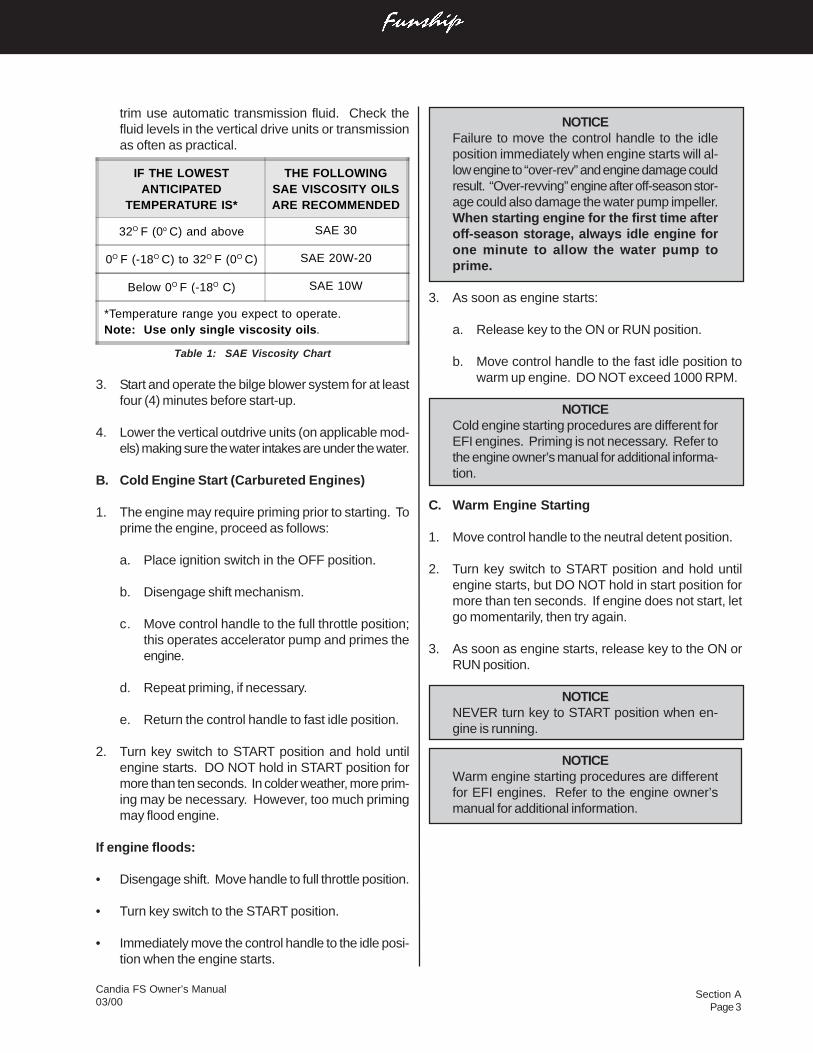
2. Check the fluid levels of the engine oil and powersteering system daily. Fill oil or steering fluid as re-quired by the indications on the dip sticks. Refer tothe Table 1: “SAE Viscosity Chart” and your enginemanual included in the owner’s packet. DO NOTUSE MULTIGRADE OIL. Power steering and power
Section APage 3
Candia FS Owner’s Manual03/00
trim use automatic transmission fluid. Check thefluid levels in the vertical drive units or transmissionas often as practical.
Table 1: SAE Viscosity Chart
3. Start and operate the bilge blower system for at leastfour (4) minutes before start-up.
4. Lower the vertical outdrive units (on applicable mod-els) making sure the water intakes are under the water.
B. Cold Engine Start (Carbureted Engines)
1. The engine may require priming prior to starting. Toprime the engine, proceed as follows:
a. Place ignition switch in the OFF position.
b. Disengage shift mechanism.
c. Move control handle to the full throttle position;this operates accelerator pump and primes theengine.
d. Repeat priming, if necessary.
e. Return the control handle to fast idle position.
2. Turn key switch to START position and hold untilengine starts. DO NOT hold in START position formore than ten seconds. In colder weather, more prim-ing may be necessary. However, too much primingmay flood engine.
If engine floods:
• Disengage shift. Move handle to full throttle position.
• Turn key switch to the START position.
• Immediately move the control handle to the idle posi-tion when the engine starts.
IF THE LOWESTANTICIPATED
TEMPERATURE IS*
THE FOLLOWINGSAE VISCOSITY OILSARE RECOMMENDED
32O F (0o C) and above SAE 30
0O F (-18O C) to 32O F (0O C) SAE 20W-20
Below 0O F (-18O C) SAE 10W
*Temperature range you expect to operate.Note: Use only single viscosity oils.
NOTICEFailure to move the control handle to the idleposition immediately when engine starts will al-low engine to “over-rev” and engine damage couldresult. “Over-revving” engine after off-season stor-age could also damage the water pump impeller.When starting engine for the first time afteroff-season storage, always idle engine forone minute to allow the water pump toprime.
3. As soon as engine starts:
a. Release key to the ON or RUN position.
b. Move control handle to the fast idle position towarm up engine. DO NOT exceed 1000 RPM.
NOTICECold engine starting procedures are different forEFI engines. Priming is not necessary. Refer tothe engine owner’s manual for additional informa-tion.
C. Warm Engine Starting
1. Move control handle to the neutral detent position.
2. Turn key switch to START position and hold untilengine starts, but DO NOT hold in start position formore than ten seconds. If engine does not start, letgo momentarily, then try again.
3. As soon as engine starts, release key to the ON orRUN position.
NOTICENEVER turn key to START position when en-gine is running.
NOTICEWarm engine starting procedures are differentfor EFI engines. Refer to the engine owner’smanual for additional information.
Section APage 4
Candia FS Owner’s Manual03/00
Any time the boat is operated, be aware ofchanges in shift system operation. A suddenincrease in shift effort at the remote controlhandle, or other abnormal operation, indicatesa possible problem in the shift system. If thisoccurs, the following precautions must be taken:
• With engine running and boat securely tiedto the dock, shift drive into forward and re-verse to ensure there is gear engagement.
• When docking the boat, all docking maneu-vers must be performed at slow speed. Payspecial attention to other boaters. Passen-gers should be informed of potential prob-lems and precautions taken.
If you suspect there is a problem, see your Volvo Pentadealer as soon as possible for proper diagnosis and re-quired service or adjustment. Continued operation couldresult in damage to the shift mechanism and loss of con-trol.
E. Stopping Engine
1. Move control handle to the NEUTRAL position.
2. Turn ignition key to the OFF position.
NOTICEDO NOT stop engine at speeds above idle or“speed up” engine while turning off ignition.Engine damage could result.
A - 10 GROUNDING AND TOWING
If the boat should become disabled, or if assist-ing another craft that is disabled, great care mustbe taken. The stress applied to a boat duringtowing may become excessive. Excessivestress can damage the structure of the boat andcreate a safety hazard for those aboard.
D. Shifting and Control Speed
NOTICEIf your boat is equipped with a non-OEM remotecontrol system, ask your dealer how to properlyoperate it.
1. Move control handle to the neutral detent (idle) posi-tion. This will engage neutral start switch and allowengine to start.
DO NOT shift into FORWARD or REVERSE un-less engine is running. Damage to the shift sys-tem could result from trying to shift without theengine running. Carefully check function of allcontrol and engine systems before leaving thedock.
2. To go FORWARD - actuate the neutral lock mecha-nism and briskly move the shift handle forward. Throttlemovement will begin after forward gear engagement.
3. To go in REVERSE - actuate the neutral lock mecha-nism and briskly move the shift handle rearward.Throttle movement will begin after reverse gear en-gagement.
DO NOT shift from forward to reverse when theboat is planing.
NOTICEDO NOT shift if engine speed is above 800 RPM.
4. To go from FORWARD to REVERSE, or REVERSEto FORWARD; always pause at NEUTRAL and allowengine speed to return to idle.
5. After shifting is completed, continue to move the con-trol handle slowly in the desired direction to increasespeed.
Section APage 5
Candia FS Owner’s Manual03/00
Four Winns® boats are not designed nor intended to beused as a towing vessel. The mooring cleats onFour Winns® boats are not designed or intended to beused for towing purposes. These cleats are specificallydesigned as mooring cleats for securing the boat to adock, pier, etc. DO NOT use these fittings for towing orattempting to free a grounded vessel.
Freeing a grounded vessel or towing a boat that is dis-abled requires specialized equipment and knowledge.Line failure and structural damage caused by impropertowing have resulted in fatal injuries. Because of this,Four Winns strongly suggests that these activities beleft to those who have the equipment and knowledge suchas the U.S. Coast Guard, to safely accomplish the tow-ing task.
Running aground can cause serious damage toa boat and associated underwater gear. If theboat should become grounded, distribute per-sonal flotation devices and inspect the boat forpossible damage. Thoroughly inspect the bilgearea for signs of leakage. An experienced ser-vice facility should check the hull and underwatergear at the first opportunity. DO NOT continueto use the boat if the condition of the hull or un-derwater equipment is questionable.
If towing or being towed is absolutely necessary, use thestrongest lines available, and attach them to the boweyes or stern eyes only. Have all passengers slip on lifejackets and take a seat in the cabin or other protectedarea.
Lines can snap or other hardware can be loos-ened or broken while towing. Under certain con-ditions, this can cause severe injury or fatality.
A - 11 BOATING EDUCATION
A. Boating Courses
Boating education classes are offered throughout thecountry. The United States Coast Guard Auxiliary offersfree courses on different topics usually during the off-season. The most popular course is the “Boating Skills& Seamanship Course,” and information can be obtainedby calling 1-800-336-BOAT.
The United States Power Squadron also offers free coursesranging from basic seamanship to celestial navigation.For information, contact your local Power Squadron, orwrite: U.S.P.S., P.O. Box 30423, Raleigh, NC 27622.
The Red Cross offers power boating and canoeing classes.Contact: Director of Water Safety, American National RedCross, 17th & D Streets N.W., Washington, DC 20006.
The Canadian Power and Sail Squadron offers seaman-ship courses. Information can be obtained by calling1-800-268-3579 (Canada only).
B. Boating Manuals or Literature
A good source of information is the U.S. Coast Guard’shome study book called “The Skipper’s Course”. Thisbook may be purchased through: Superintendent of Docu-ments, U.S. Government Printing Office, Washington, DC20402, Stock # 050-012-00159-6.
Another good source of boating information is Chapman’s“Piloting, Seamanship and Small Boat Handling”. Also,check the local library or bookstore for additional informa-tion on boating.
C. Charts and Maps
U.S. nautical charts are sold throughout the country atGovernmental Printing Office stores and other agents. Achart catalog is available by writing to: National Oceanicand Atmospheric Administration, National Ocean Survey,Rockville, MD 20852.
In addition, many federal agencies publish recreationalmaps, including the U.S. Army Corp of Engineers, theForest Service, the National Park Service, and the Ten-nessee Valley Authority.
Addresses of all state boating agencies are listed in “ABoater’s Guide”. For a free copy, write to: National Ma-rine Manufacturers Association, 401 N. Michigan Avenue,Chicago, IL 60611.
Section BPage 1
Candia FS Owner’s Manual03/00
B - 1 GENERAL
As the owner/operator of the boat, you are responsiblefor assuring that all required safety equipment is aboard.You should also consider supplying additional equipmentas needed for your safety and that of your passengers.Check state and local regulations and call the U.S. CoastGuard Boating Safety Hotline at 1-800-368-5647 for in-formation about required safety for information aboutrequired safety equipment.
A. Required Safety Equipment
Most of the safety equipment required by federal regu-lations is provided as standard equipment. PersonalFloatation Devices (life jackets) must fit the person wear-ing it. If local regulations require additional equipment,it must be approved by the U.S. Coast Guard (USCG).Minimum requirements include the following:
• Personal Floatation Devices• Visual Distress Signal• Bell or Whistle• Fire Extinguisher• Navigation Lights
B. Personal Floatation Devices (PFD’s)
Federal regulations require that you have at least oneCoast Guard approved personal floatation device (PFD)for each person in a recreational boat. You should notuse your boat unless all PDFs are in serviceable condi-tion, readily accessible, legibly marked with the CoastGuard approval number, of an appropriate size (withinthe weight range and chest size marked on the PDF)for each person aboard.
A PFD provides buoyancy to help keep your head abovethe water and to help you remain in a satisfactory posi-tion while in the water. Body weight and age should beconsidered when selecting a PFD. The buoyancy pro-vided by the PFD should support your weight in water.
The size of the PFD should be appropriate for the wearer.Body weight or chest size are common methods usedto size PFDs. It is your responsibility to ensure that youhave the proper number and types of PFD’s on boardand that your passengers know where and how to usethem.
C. PFD Types
Five types of PFDs have been approved by the U.S.Coast Guard. The PFDs are described as follows:
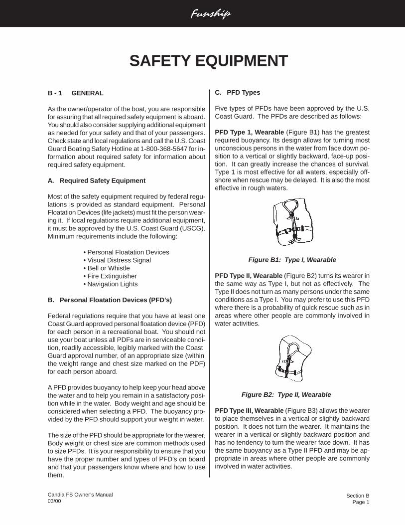
PFD Type 1, Wearable (Figure B1) has the greatestrequired buoyancy. Its design allows for turning mostunconscious persons in the water from face down po-sition to a vertical or slightly backward, face-up posi-tion. It can greatly increase the chances of survival.Type 1 is most effective for all waters, especially off-shore when rescue may be delayed. It is also the mosteffective in rough waters.
Figure B1: Type I, Wearable
PFD Type II, Wearable (Figure B2) turns its wearer inthe same way as Type I, but not as effectively. TheType II does not turn as many persons under the sameconditions as a Type I. You may prefer to use this PFDwhere there is a probability of quick rescue such as inareas where other people are commonly involved inwater activities.
Figure B2: Type II, Wearable
PFD Type III, Wearable (Figure B3) allows the wearerto place themselves in a vertical or slightly backwardposition. It does not turn the wearer. It maintains thewearer in a vertical or slightly backward position andhas no tendency to turn the wearer face down. It hasthe same buoyancy as a Type II PFD and may be ap-propriate in areas where other people are commonlyinvolved in water activities.
SAFETY EQUIPMENT
Section BPage 2
Candia FS Owner’s Manual03/00
2. To make sure the PFD works, wear it in the water.This will show you how it works and give you confi-dence when you use it.
3. Teach children how to put a PFD on and allow themto try it in the water. That way, they know what thePFD is for and how it works. They will feel morecomfortable with it if they suddenly find themselvesin the water.
4. If the PFD is wet, allow it to dry thoroughly beforestoring it. Do not dry it in front of a radiator or heater.Store it in a well ventilated area.
5. Keep PFDs away from sharp objects which cantear the fabric or puncture the floatation pads.
6. For their own safety and the safety of others, allnonswimmers, poor swimmers, and small childrenshould wear PFD’s at all times, whether the boat isstationary or moving.
7. Check the PFD frequently to make sure that it isnot torn, that floatation pads have no leaks, andthat all seams and joints are securely sewn.
8. If a PFD contains kapok, the kapok fibers may be-come waterlogged and lose their buoyancy afterthe vinyl inserts are punctured. If the kapok be-comes hard or if it is soaked with water, replace it.It may not work when you need it.
E. Emergency Stop Switch
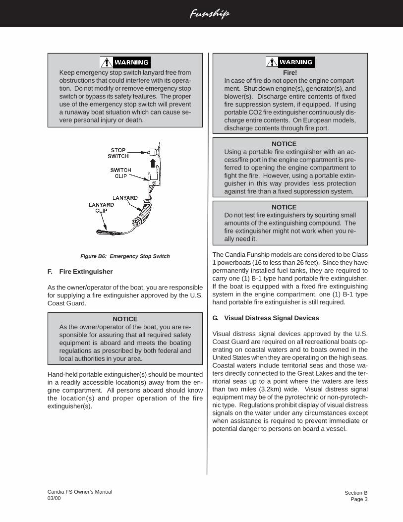
This safety device automatically stops the engine if thelanyard is attached to the operator and the operatorfalls from his work station. Refer to the engine manualfor detailed information about using this switch.
The emergency stop switch (Figure B6) incorporates ashutoff switch, switch clip, lanyard, and lanyard clip. Thelanyard clip must be securely attached to the operator’sPFD, clothing, arm, or leg. Be sure to attach the lan-yard to a place where it is free of obstructions and tosomething that will move with the operator if he or sheleaves the helm station. If the engine shuts down be-cause this switch was activated, the clip may have tobe reinstalled on the interrupter switch before the en-gine can be started.
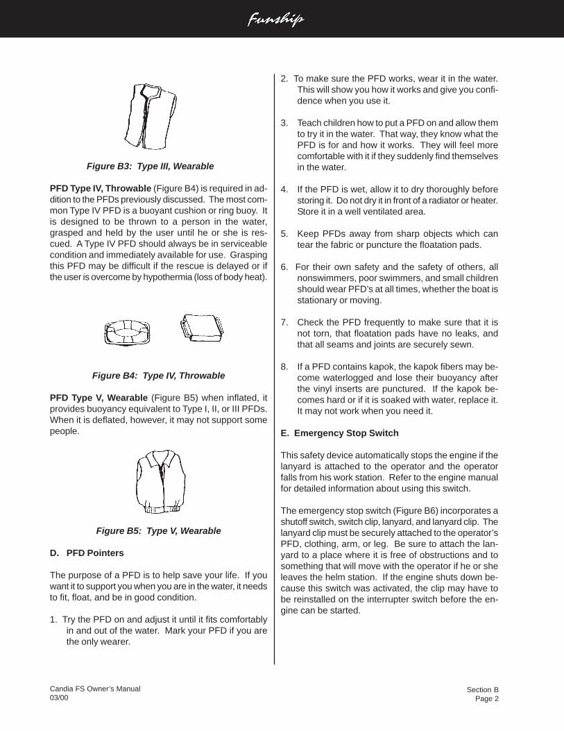
Figure B3: Type III, Wearable
PFD Type IV, Throwable (Figure B4) is required in ad-dition to the PFDs previously discussed. The most com-mon Type IV PFD is a buoyant cushion or ring buoy. Itis designed to be thrown to a person in the water,grasped and held by the user until he or she is res-cued. A Type IV PFD should always be in serviceablecondition and immediately available for use. Graspingthis PFD may be difficult if the rescue is delayed or ifthe user is overcome by hypothermia (loss of body heat).
Figure B4: Type IV, Throwable
PFD Type V, Wearable (Figure B5) when inflated, itprovides buoyancy equivalent to Type I, II, or III PFDs.When it is deflated, however, it may not support somepeople.
Figure B5: Type V, Wearable
D. PFD Pointers
The purpose of a PFD is to help save your life. If youwant it to support you when you are in the water, it needsto fit, float, and be in good condition.
1. Try the PFD on and adjust it until it fits comfortablyin and out of the water. Mark your PFD if you arethe only wearer.
Section BPage 3
Candia FS Owner’s Manual03/00
Keep emergency stop switch lanyard free fromobstructions that could interfere with its opera-tion. Do not modify or remove emergency stopswitch or bypass its safety features. The properuse of the emergency stop switch will preventa runaway boat situation which can cause se-vere personal injury or death.
Figure B6: Emergency Stop Switch
F. Fire Extinguisher
As the owner/operator of the boat, you are responsiblefor supplying a fire extinguisher approved by the U.S.Coast Guard.
NOTICEAs the owner/operator of the boat, you are re-sponsible for assuring that all required safetyequipment is aboard and meets the boatingregulations as prescribed by both federal andlocal authorities in your area.
Hand-held portable extinguisher(s) should be mountedin a readily accessible location(s) away from the en-gine compartment. All persons aboard should knowthe location(s) and proper operation of the fireextinguisher(s).
Fire!In case of fire do not open the engine compart-ment. Shut down engine(s), generator(s), andblower(s). Discharge entire contents of fixedfire suppression system, if equipped. If usingportable CO2 fire extinguisher continuously dis-charge entire contents. On European models,discharge contents through fire port.
NOTICEUsing a portable fire extinguisher with an ac-cess/fire port in the engine compartment is pre-ferred to opening the engine compartment tofight the fire. However, using a portable extin-guisher in this way provides less protectionagainst fire than a fixed suppression system.
NOTICEDo not test fire extinguishers by squirting smallamounts of the extinguishing compound. Thefire extinguisher might not work when you re-ally need it.
The Candia Funship models are considered to be Class1 powerboats (16 to less than 26 feet). Since they havepermanently installed fuel tanks, they are required tocarry one (1) B-1 type hand portable fire extinguisher.If the boat is equipped with a fixed fire extinguishingsystem in the engine compartment, one (1) B-1 typehand portable fire extinguisher is still required.
G. Visual Distress Signal Devices
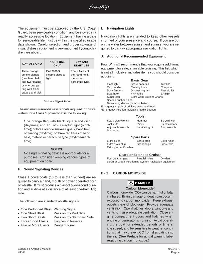
Visual distress signal devices approved by the U.S.Coast Guard are required on all recreational boats op-erating on coastal waters and to boats owned in theUnited States when they are operating on the high seas.Coastal waters include territorial seas and those wa-ters directly connected to the Great Lakes and the ter-ritorial seas up to a point where the waters are lessthan two miles (3.2km) wide. Visual distress signalequipment may be of the pyrotechnic or non-pyrotech-nic type. Regulations prohibit display of visual distresssignals on the water under any circumstances exceptwhen assistance is required to prevent immediate orpotential danger to persons on board a vessel.
Section BPage 4
Candia FS Owner’s Manual03/00
I. Navigation Lights
Navigation lights are intended to keep other vesselsinformed of your presence and course. If you are outon the water between sunset and sunrise, you are re-quired to display appropriate navigation lights.
J. Additional Recommended Equipment
Four Winns® recommends that you acquire additionalequipment for safe, enjoyable cruising. This list, whichis not all inclusive, includes items you should consideracquiring.
Basic GearFlashlight Spare batteries Tow lineOar, paddle Mooring lines CompassDock fenders Distress signals First aid kitBoat hook VHF radio EPIRB*Sunscreen Extra warm clothing ChartsSecond anchor & lineDewatering device (pump or bailer)
Emergency supply of drinking water and food.*Emergency Position Indicating Radio Beacon
ToolsSpark plug wrench Hammer ScrewdriverJackknife Pliers Electrical tapeAdjustable wrench Lubricating oil Prop wrenchDuct tape
Spare PartsExtra bulbs Spare prop Extra fusesExtra drain plug Spark plugs Spare wireExtra prop nut/washer
Gear For Extended CruisesFoul weather gear Parallel rulers DividersLoran or Global Positioning System navigation equipment
B - 2 CARBON MONOXIDE
Carbon Monoxide!Carbon monoxide (CO) can be harmful or fatalif inhaled. Brain damage or death can occur ifexposed to carbon monoxide. Keep exhaustoutlets clear of blockage. Provide adequateventilation. Open hatches, doors, windows andvents to insure adequate ventilation. Close en-gine compartment doors and hatches whenengine or generator is running. Avoid operat-ing the boat for extended periods of time atidle speed, and be sensitive to weather condi-tions that may prevent CO from dissipating intothe air. (See Preface for actual warning labelregarding carbon monoxide.)
The equipment must be approved by the U.S. CoastGuard, be in serviceable condition, and be stowed in areadily accessible location. Equipment having a datefor serviceable life must be within the specified usagedate shown. Careful selection and proper stowage ofvisual distress equipment is very important if young chil-dren are aboard.
DAY USE ONLYNIGHT USE
ONLYDAY AND
NIGHT USE
Three orangesmoke signals(one hand heldand two floating)or one orangeflag with blacksquare and disk.
One S-O-Selectric distresslight.
Three flares ofthe hand held,meteor orparachute type.
Distress Signal Table
The minimum visual distress signals required in coastalwaters for a Class 1 powerboat is the following:
One orange flag with black square-and disc(daytime); and an S-O-S electric light (night-time); or three orange smoke signals, hand heldor floating (daytime); or three red flares of handheld, meteor, or parachute type (daytime/night-time).
NOTICENo single signaling device is appropriate for allpurposes. Consider keeping various types ofequipment on board.
H. Sound Signaling Devices
Class 1 powerboats (16 to less than 26 feet) are re-quired to carry a hand, mouth or power operated hornor whistle. It must produce a blast of two-second dura-tion and audible at a distance of at least one-half (1/2)mile.
The following are standard whistle signals:
• One Prolonged Blast Warning Signal• One Short Blast Pass on my Port Side• Two Short Blasts Pass on my Starboard Side• Three Short Blasts Engines in Reverse• Five or More Blasts Danger Signal
Section BPage 5
Candia FS Owner’s Manual03/00
Common sources of carbon monoxide are:
1. Internal combustion engines.
2. Open flame devices such as:
a. Cooking rangesb. Central heating plantsc. Space heatersd. Water heaterse. Fireplacesf. Charcoal grills
C. How a Person is Affected by CarbonMonoxide
Carbon monoxide is absorbed by the lungs and reactswith blood hemoglobin to form carboxyhemoglobin, whichreduces the oxygen carrying capacity of the blood. Theresult is a lack of oxygen for the tissues with the subse-quent tissue death and, if prolonged, death of the in-dividual.
D. Effects of Carbon Monoxide
Carbon monoxide in high concentrations can be fatal ina matter of minutes. Lower concentrations must not beignored because the effects of exposure to CO are cu-mulative and can be just as lethal.
Certain health related problems and age will increasethe effects of CO. People who smoke or are exposed tohigh concentrations of cigarette smoke, consume alco-hol or have lung disorders or heart problems, are par-ticularly susceptible to an increase in the effects fromCO. However, all occupants’ health should be consid-ered. Physical exertion accelerates the rate at whichthe blood absorbs CO.
E. Symptoms
One or more of the following symptoms can signal theadverse effect of CO accumulation:
1. Watering and itchy eyes2. Flushed appearance3. Throbbing temples4. Inattentiveness5. Inability to think coherently6. Ringing in the ears7. Tightness across the chest8. Headache9. Drowsiness
Carbon monoxide accumulation is affected by vessel ge-ometry; hatch, window and door openings; ventilationopenings; proximity to other structures; wind direction;vessel speed; and a multitude of other variables. Thetechnical information included in this section is to informthe boat owner of possible cause and effects of carbonmonoxide. This information has been reprinted with per-mission from the American Boat and Yacht Council’s(ABYC) technical information report: “Educational In-formation About Carbon Monoxide”. This informationpertains to all boats manufactured by Four Winns®.
NOTICEThe boat owner should be aware that other fac-tors may contribute to carbon monoxide accu-mulation. The most common ones are listed inthis section. If a person is exhibiting carbonmonoxide-type symptoms (Refer to B-2E Symp-toms), be sure to take the necessary precau-tions as prescribed later in this section.
NOTICEBoats fueled by diesel have limited carbon mon-oxide present in the exhaust in comparison togasoline engine exhaust. However, the boatowner should still be aware of the causes andeffects of carbon monoxide which may occur indifferent boating situations.
A. Properties and Characteristics of Carbon Mon-oxide
1. Carbon Monoxide is a colorless, odorless and taste-less gas. It is commonly referred to as CO.
2. Its weight is about the same as air so it cannot beexpected to rise or fall like some other gases, butwill distribute itself throughout the space.
NOTICEDO NOT rely on the use of smell or sight ofother gases to detect CO, because it diffuses inthe air much more rapidly than easily detectable(visible and odorous) gases.
B. What Makes Carbon Monoxide
Any time a material containing carbon burns such asgasoline, natural gas, oil, propane, coal, or wood, CO isproduced.
Section BPage 6
Candia FS Owner’s Manual03/00
3. Make sure gaps around the engine room plumbingand cableways and exhaust system doors, hatches,and access panels are minimized to reduce the op-portunity for CO to enter the accommodationspace(s).
H. Operation
Cold Start vs. Warm Start: CO production is greater whilethe combustion chamber surfaces and gas passagesare cold versus when they are warm. A boat operatorshould:
1. Pay attention to ventilating the boat.
2. Orient the boat so it will allow the maximum dissipa-tion of CO.
3. Minimize the time spent on getting underway.
The following are examples of possible situa-tions where carbon monoxide can accumulatewithin your boat while docked, anchored, or un-derway. Become familiar with these examplesand their precautions to prevent dangerousaccidents or death.
I. Boathouses, Sea Walls and Other Boats
A boat operator should be aware that dangerous con-centrations of CO can accumulate when a boat, genera-tor or other engine operated device is operated while theboat is moored in a confined area such as:
1. Boathouses,
2. Proximity to sea walls, or
3. Proximity to other boats.
Orient the boat for maximum dissipation of the exhaustor DO NOT run the boat or boat equipment for extendedperiods under these conditions. See Figure B7.
10. Incoherence11. Nausea12. Dizziness13. Fatigue14. Vomiting15. Collapse16. Convulsions
NOTICEThe order of the above list is generally the se-quence of appearance of symptoms. However,the order of appearance may change for differ-ent people.
NOTICEThe symptoms of Carbon monoxide poison-ing may easily be mistaken for seasickness.
F. Treatment (Evacuate, Ventilate, Investigate, TakeCorrective Action)
1. Move the person to fresh air.
2. Administer oxygen if available.
3. Contact Medical help.
4. If the victim is not breathing, perform artificial respi-ration per approved CPR procedures until medicalhelp arrives and takes over.
NOTICEPrompt action can make the difference betweenlife and death.
5. Ventilate area.
6. Investigate source of CO and take corrective ac-tion.
G. Inspection
Look and listen for leaks in the exhaust systems of boththe generator and propulsion engine(s). Look for discol-oration around joints in the system (water leaks, carbon,stains, etc.).
1. Make sure all exhaust clamps are in place and se-cured.
2. Make sure ventilation systems work and are not ob-structed or restricted.
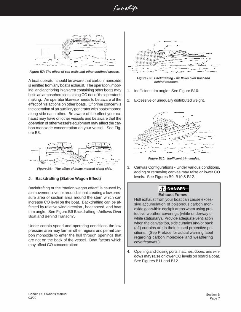
Section BPage 7
Candia FS Owner’s Manual03/00
Figure B9: Backdrafting - Air flows over boat and behind transom.
1. Inefficient trim angle. See Figure B10.
2. Excessive or unequally distributed weight.
Figure B10: Inefficient trim angles.
3. Canvas Configurations - Under various conditions,adding or removing canvas may raise or lower COlevels. See Figures B9, B10 & B12.
Exhaust Fumes!Hull exhaust from your boat can cause exces-sive accumulation of poisonous carbon mon-oxide gas within cockpit areas when using pro-tective weather coverings (while underway orwhile stationary). Provide adequate ventilationwhen the canvas top, side curtains and/or back(aft) curtains are in their closed protective po-sitions. (See Preface for actual warning labelregarding carbon monoxide and weatheringcover/canvas.)
4. Opening and closing ports, hatches, doors, and win-dows may raise or lower CO levels on board a boat.See Figures B11 and B12.
Figure B7: The effect of sea walls and other confined spaces.
A boat operator should be aware that carbon monoxideis emitted from any boat’s exhaust. The operation, moor-ing, and anchoring in an area containing other boats maybe in an atmosphere containing CO not of the operator’smaking. An operator likewise needs to be aware of theeffect of his actions on other boats. Of prime concern isthe operation of an auxiliary generator with boats mooredalong side each other. Be aware of the effect your ex-haust may have on other vessels and be aware that theoperation of other vessel’s equipment may affect the car-bon monoxide concentration on your vessel. See Fig-ure B8.
Figure B8: The effect of boats moored along side.
J. Backdrafting (Station Wagon Effect)
Backdrafting or the “station wagon effect” is caused byair movement over or around a boat creating a low pres-sure area of suction area around the stern which canincrease CO level on the boat. Backdrafting can be af-fected by relative wind direction , boat speed, and boattrim angle. See Figure B9 Backdrafting - Airflows OverBoat and Behind Transom”.
Under certain speed and operating conditions the lowpressure area may form in other regions and permit car-bon monoxide to enter the hull through openings thatare not on the back of the vessel. Boat factors whichmay affect CO concentration:
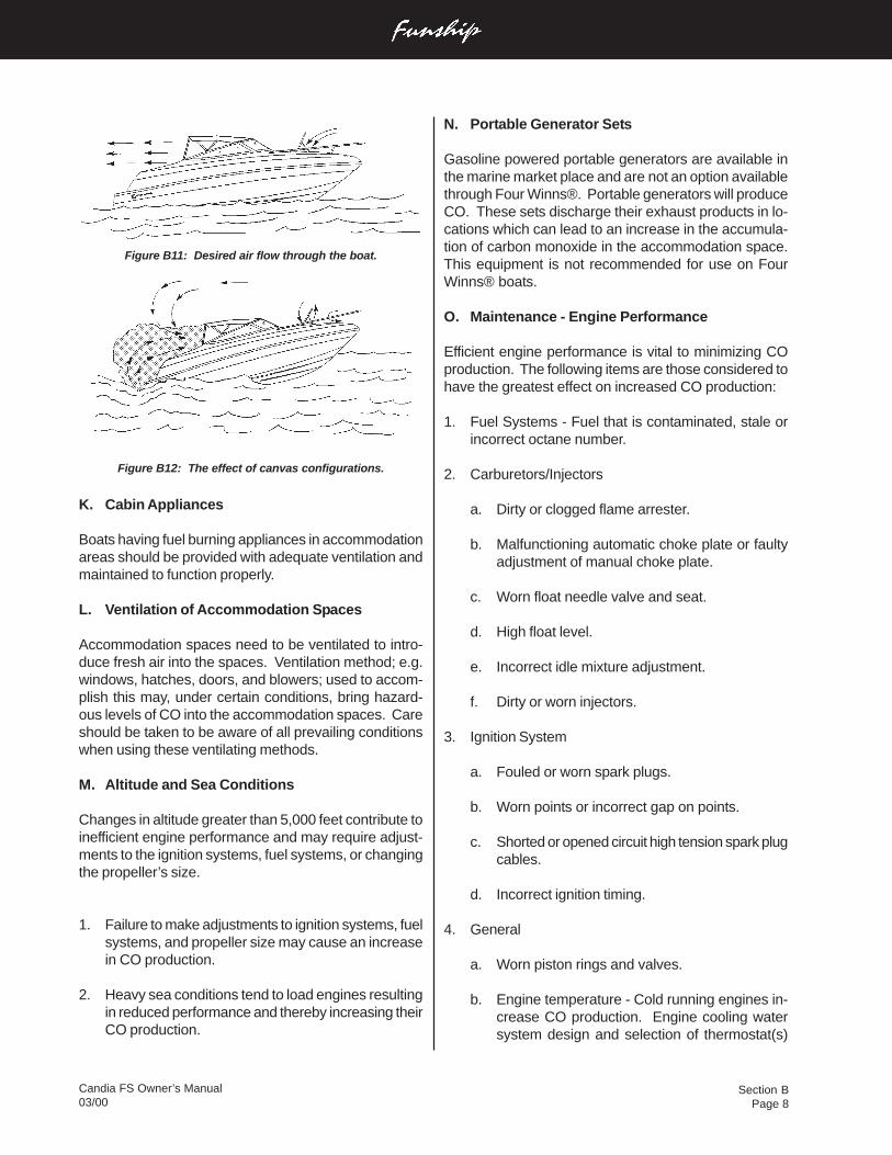
Section BPage 8
Candia FS Owner’s Manual03/00
N. Portable Generator Sets
Gasoline powered portable generators are available inthe marine market place and are not an option availablethrough Four Winns®. Portable generators will produceCO. These sets discharge their exhaust products in lo-cations which can lead to an increase in the accumula-tion of carbon monoxide in the accommodation space.This equipment is not recommended for use on FourWinns® boats.
O. Maintenance - Engine Performance
Efficient engine performance is vital to minimizing COproduction. The following items are those considered tohave the greatest effect on increased CO production:
1. Fuel Systems - Fuel that is contaminated, stale orincorrect octane number.
2. Carburetors/Injectors
a. Dirty or clogged flame arrester.
b. Malfunctioning automatic choke plate or faultyadjustment of manual choke plate.
c. Worn float needle valve and seat.
d. High float level.
e. Incorrect idle mixture adjustment.
f. Dirty or worn injectors.
3. Ignition System
a. Fouled or worn spark plugs.
b. Worn points or incorrect gap on points.
c. Shorted or opened circuit high tension spark plugcables.
d. Incorrect ignition timing.
4. General
a. Worn piston rings and valves.
b. Engine temperature - Cold running engines in-crease CO production. Engine cooling watersystem design and selection of thermostat(s)
Figure B11: Desired air flow through the boat.
Figure B12: The effect of canvas configurations.
K. Cabin Appliances
Boats having fuel burning appliances in accommodationareas should be provided with adequate ventilation andmaintained to function properly.
L. Ventilation of Accommodation Spaces
Accommodation spaces need to be ventilated to intro-duce fresh air into the spaces. Ventilation method; e.g.windows, hatches, doors, and blowers; used to accom-plish this may, under certain conditions, bring hazard-ous levels of CO into the accommodation spaces. Careshould be taken to be aware of all prevailing conditionswhen using these ventilating methods.
M. Altitude and Sea Conditions
Changes in altitude greater than 5,000 feet contribute toinefficient engine performance and may require adjust-ments to the ignition systems, fuel systems, or changingthe propeller’s size.
1. Failure to make adjustments to ignition systems, fuelsystems, and propeller size may cause an increasein CO production.
2. Heavy sea conditions tend to load engines resultingin reduced performance and thereby increasing theirCO production.
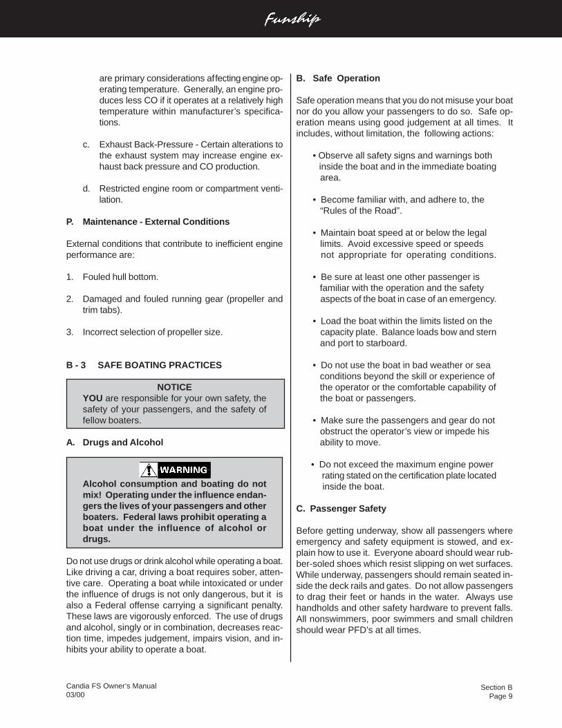
Section BPage 9
Candia FS Owner’s Manual03/00
are primary considerations affecting engine op-erating temperature. Generally, an engine pro-duces less CO if it operates at a relatively hightemperature within manufacturer’s specifica-tions.
c. Exhaust Back-Pressure - Certain alterations tothe exhaust system may increase engine ex-haust back pressure and CO production.
d. Restricted engine room or compartment venti-lation.
P. Maintenance - External Conditions
External conditions that contribute to inefficient engineperformance are:
1. Fouled hull bottom.
2. Damaged and fouled running gear (propeller andtrim tabs).
3. Incorrect selection of propeller size.
B - 3 SAFE BOATING PRACTICES
NOTICEYOU are responsible for your own safety, thesafety of your passengers, and the safety offellow boaters.
A. Drugs and Alcohol
Alcohol consumption and boating do notmix! Operating under the influence endan-gers the lives of your passengers and otherboaters. Federal laws prohibit operating aboat under the influence of alcohol ordrugs.
Do not use drugs or drink alcohol while operating a boat.Like driving a car, driving a boat requires sober, atten-tive care. Operating a boat while intoxicated or underthe influence of drugs is not only dangerous, but it isalso a Federal offense carrying a significant penalty.These laws are vigorously enforced. The use of drugsand alcohol, singly or in combination, decreases reac-tion time, impedes judgement, impairs vision, and in-hibits your ability to operate a boat.
B. Safe Operation
Safe operation means that you do not misuse your boatnor do you allow your passengers to do so. Safe op-eration means using good judgement at all times. Itincludes, without limitation, the following actions:
• Observe all safety signs and warnings both inside the boat and in the immediate boating area.
• Become familiar with, and adhere to, the “Rules of the Road”.
• Maintain boat speed at or below the legal limits. Avoid excessive speed or speeds not appropriate for operating conditions.
• Be sure at least one other passenger is familiar with the operation and the safety aspects of the boat in case of an emergency.
• Load the boat within the limits listed on the capacity plate. Balance loads bow and stern and port to starboard.
• Do not use the boat in bad weather or sea conditions beyond the skill or experience of the operator or the comfortable capability of the boat or passengers.
• Make sure the passengers and gear do not obstruct the operator’s view or impede his ability to move.
• Do not exceed the maximum engine power rating stated on the certification plate located inside the boat.
C. Passenger Safety
Before getting underway, show all passengers whereemergency and safety equipment is stowed, and ex-plain how to use it. Everyone aboard should wear rub-ber-soled shoes which resist slipping on wet surfaces.While underway, passengers should remain seated in-side the deck rails and gates. Do not allow passengersto drag their feet or hands in the water. Always usehandholds and other safety hardware to prevent falls.All nonswimmers, poor swimmers and small childrenshould wear PFD’s at all times.
Section BPage 10
Candia FS Owner’s Manual03/00
F. Operation By Minors
Minors should always be supervised by an adult when-ever operating a boat. Many states have laws regard-ing the minimum age and licensing requirements ofminors. Be sure to check local laws or contact the stateboating authorities for information.
G. “Rules of the Road”
As a responsible boater, you must comply with the“Rules of the Road,” the marine traffic laws enforcedby the U.S. Coast Guard. Navigating a boat is muchthe same as driving an automobile. Operating eitherone responsibly means complying with a set of rulesintended to prevent accidents. Just as you assumeother car drivers know what they are doing, other boat-ers assume you know what you are doing. Informationregarding navigational rules and the “Rules of the Road”are discussed in further detail in C-1 & C-2 of the nextsection.
H. Voluntary Inspections
State boating officials in many states or the U.S. CoastGuard Auxiliaries offer courtesy inspections to checkout your craft. They will check for compliance with safetystandards and required safety equipment. You mayvoluntarily consent to one of these inspections, and youare allowed to make corrections without prosecution.Check with the appropriate state agency or the CoastGuard Auxiliary for details.
I. Safe Boating Courses
The local U.S. Coast Guard Auxiliary and the U.S. PowerSquadrons offer comprehensive safe boating classesseveral times a year. You may contact the Boat/U.S.Foundation at 1-800-336-BOAT (2628) or, in Virginia,1-800-245-BOAT (2628) for a course scheduled in yourarea. Also contact the U.S. Coast Guard Auxiliary orPower Squadron Flotilla for the time and place of theirnext scheduled class.
D. Propeller
Personal Injury!Do not allow anyone near a propeller, evenwhen the engine is off. Propeller blades canbe sharp and continue to turn even after theengine is shut off. Do not allow anyone nearthe propeller when the throttle is in neutral po-sition. Accidently engaging the shift can resultin a serious injury or death. (See actual ladderwarning labels and helm boarding ladder warn-ing label below.)
Never approach or use ladder when motor isrunning. Severe injury or death will result fromcontact with rotating propeller.
Ladder Warning Label
Shut off motor when near swimmers. Severeinjury or death will result from contact with ro-tating propeller.
Helm Boarding Ladder Warning Label
When pulling skiers do not turn on the engineuntil you are at least a boat length away. Whenapproaching a downed skier, turn off the en-gine at least one boat length away before reach-ing the skier in the water.
E. First Aid
As a boater, you should be familiar with the basic firstaid procedures that may be needed while you are outfar from help. Fish hook accidents or minor cuts andabrasions may be the most serious mishaps on boarda boat but you should also learn the proper proceduresand be ready to deal with the truly serious problemslike mouth-to-mouth resuscitation, excessive bleeding,hypothermia, and burns. First aid literature and coursesare available through most Red Cross chapters.
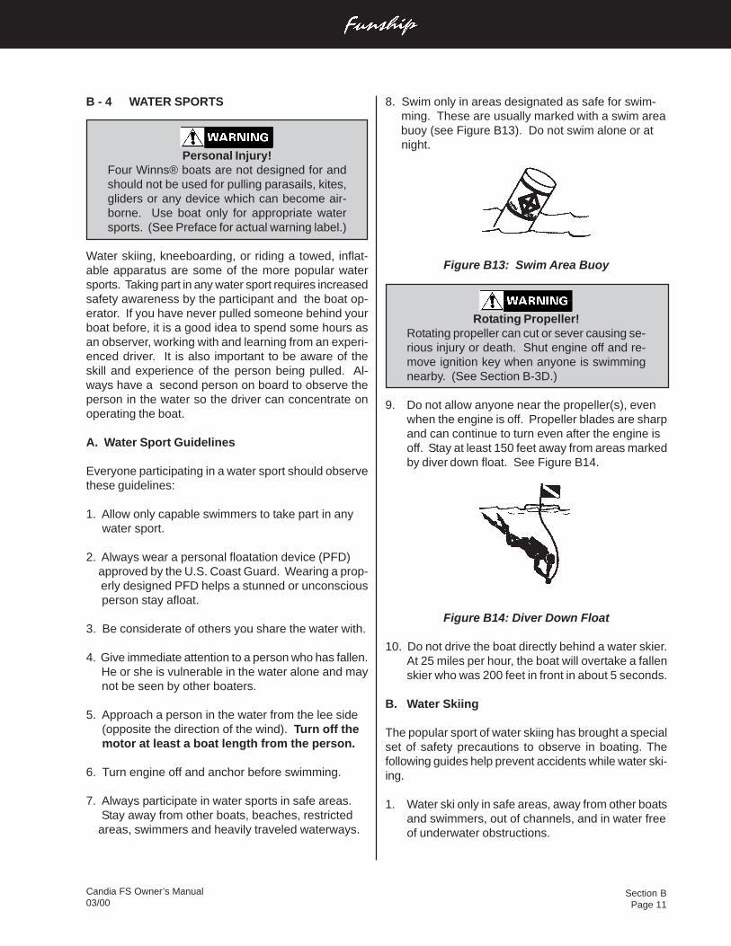
Section BPage 11
Candia FS Owner’s Manual03/00
8. Swim only in areas designated as safe for swim- ming. These are usually marked with a swim area buoy (see Figure B13). Do not swim alone or at night.
Figure B13: Swim Area Buoy
Rotating Propeller!Rotating propeller can cut or sever causing se-rious injury or death. Shut engine off and re-move ignition key when anyone is swimmingnearby. (See Section B-3D.)
9. Do not allow anyone near the propeller(s), evenwhen the engine is off. Propeller blades are sharpand can continue to turn even after the engine isoff. Stay at least 150 feet away from areas markedby diver down float. See Figure B14.
Figure B14: Diver Down Float
10. Do not drive the boat directly behind a water skier.At 25 miles per hour, the boat will overtake a fallenskier who was 200 feet in front in about 5 seconds.
B. Water Skiing
The popular sport of water skiing has brought a specialset of safety precautions to observe in boating. Thefollowing guides help prevent accidents while water ski-ing.
1. Water ski only in safe areas, away from other boatsand swimmers, out of channels, and in water freeof underwater obstructions.
B - 4 WATER SPORTS
Personal Injury!Four Winns® boats are not designed for andshould not be used for pulling parasails, kites,gliders or any device which can become air-borne. Use boat only for appropriate watersports. (See Preface for actual warning label.)
Water skiing, kneeboarding, or riding a towed, inflat-able apparatus are some of the more popular watersports. Taking part in any water sport requires increasedsafety awareness by the participant and the boat op-erator. If you have never pulled someone behind yourboat before, it is a good idea to spend some hours asan observer, working with and learning from an experi-enced driver. It is also important to be aware of theskill and experience of the person being pulled. Al-ways have a second person on board to observe theperson in the water so the driver can concentrate onoperating the boat.
A. Water Sport Guidelines
Everyone participating in a water sport should observethese guidelines:
1. Allow only capable swimmers to take part in any water sport.
2. Always wear a personal floatation device (PFD) approved by the U.S. Coast Guard. Wearing a prop- erly designed PFD helps a stunned or unconscious person stay afloat.
3. Be considerate of others you share the water with.
4. Give immediate attention to a person who has fallen. He or she is vulnerable in the water alone and may not be seen by other boaters.
5. Approach a person in the water from the lee side (opposite the direction of the wind). Turn off the motor at least a boat length from the person.
6. Turn engine off and anchor before swimming.
7. Always participate in water sports in safe areas. Stay away from other boats, beaches, restricted areas, swimmers and heavily traveled waterways.
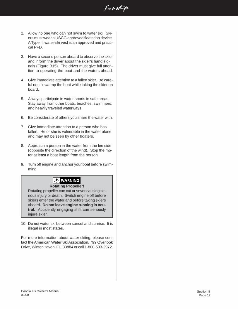
Section BPage 12
Candia FS Owner’s Manual03/00
2. Allow no one who can not swim to water ski. Ski-ers must wear a USCG approved floatation device.A Type III water-ski vest is an approved and practi-cal PFD.
3. Have a second person aboard to observe the skierand inform the driver about the skier’s hand sig-nals (Figure B15). The driver must give full atten-tion to operating the boat and the waters ahead.
4. Give immediate attention to a fallen skier. Be care-ful not to swamp the boat while taking the skier onboard.
5. Always participate in water sports in safe areas.Stay away from other boats, beaches, swimmers,and heavily traveled waterways.
6. Be considerate of others you share the water with.
7. Give immediate attention to a person who hasfallen. He or she is vulnerable in the water aloneand may not be seen by other boaters.
8. Approach a person in the water from the lee side(opposite the direction of the wind). Stop the mo-tor at least a boat length from the person.
9. Turn off engine and anchor your boat before swim-ming.
Rotating Propeller!Rotating propeller can cut or sever causing se-rious injury or death. Switch engine off beforeskiers enter the water and before taking skiersaboard. Do not leave engine running in neu-tral. Accidently engaging shift can seriouslyinjure skier.
10. Do not water ski between sunset and sunrise. It isillegal in most states.
For more information about water skiing, please con-tact the American Water Ski Association, 799 OverlookDrive, Winter Haven, FL. 33884 or call 1-800-533-2972.
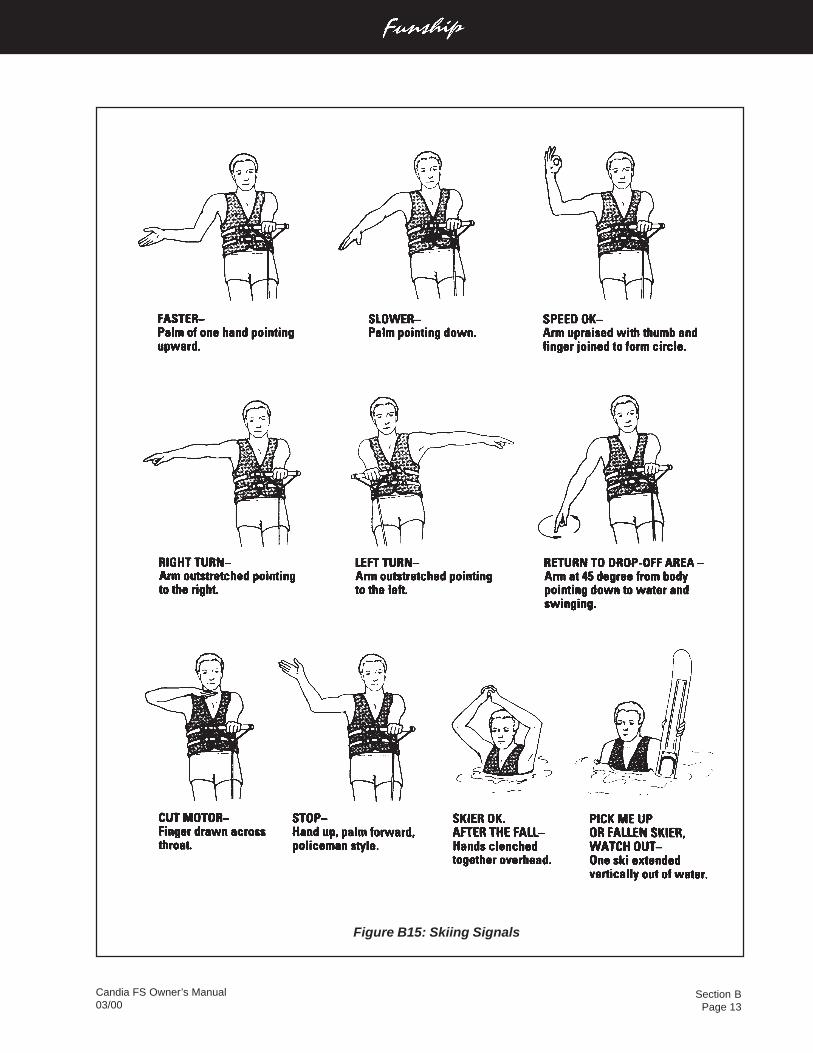
Section BPage 13
Candia FS Owner’s Manual03/00
Figure B15: Skiing Signals
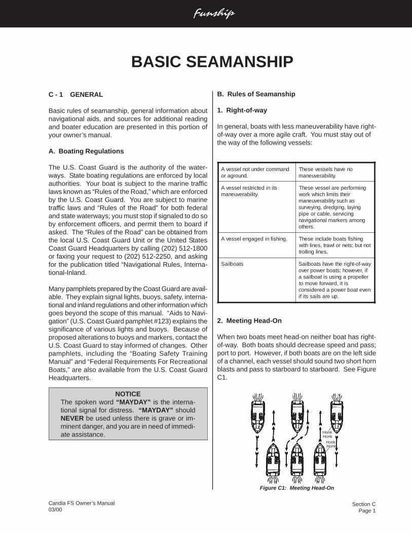
Section CPage 1
Candia FS Owner’s Manual03/00
Figure C1: Meeting Head-On
B. Rules of Seamanship
1. Right-of-way
In general, boats with less maneuverability have right-of-way over a more agile craft. You must stay out ofthe way of the following vessels:
dnammocrednutonlessevA.dnuorgaro
onevahslessevesehT.ytilibarevuenam
stinidetcirtserlessevA.ytilibarevuenam
gnimrofreperalessevesehTriehtstimilhcihwkrow
sahcusytilibarevuenamgniyal,gnigderd,gniyevrus
gnicivres,elbacroepipgnomasrekramlanoitagivan
.srehto
.gnihsifnidegagnelessevA gnihsifstaobedulcniesehTtontub;stenrolwart,senilhtiw
.senilgnillort
staobliaS yaw-fo-thgirehtevahstaobliaSfi,revewoh;staobrewoprevorelleporpagnisusitaobliasa
siti,drawrofevomotnevetaobrewopaderedisnoc
.puerasliasstifi
2. Meeting Head-On
When two boats meet head-on neither boat has right-of-way. Both boats should decrease speed and pass;port to port. However, if both boats are on the left sideof a channel, each vessel should sound two short hornblasts and pass to starboard to starboard. See FigureC1.
C - 1 GENERAL
Basic rules of seamanship, general information aboutnavigational aids, and sources for additional readingand boater education are presented in this portion ofyour owner’s manual.
A. Boating Regulations
The U.S. Coast Guard is the authority of the water-ways. State boating regulations are enforced by localauthorities. Your boat is subject to the marine trafficlaws known as “Rules of the Road,” which are enforcedby the U.S. Coast Guard. You are subject to marinetraffic laws and “Rules of the Road” for both federaland state waterways; you must stop if signaled to do soby enforcement officers, and permit them to board ifasked. The “Rules of the Road” can be obtained fromthe local U.S. Coast Guard Unit or the United StatesCoast Guard Headquarters by calling (202) 512-1800or faxing your request to (202) 512-2250, and askingfor the publication titled “Navigational Rules, Interna-tional-Inland.
Many pamphlets prepared by the Coast Guard are avail-able. They explain signal lights, buoys, safety, interna-tional and inland regulations and other information whichgoes beyond the scope of this manual. “Aids to Navi-gation” (U.S. Coast Guard pamphlet #123) explains thesignificance of various lights and buoys. Because ofproposed alterations to buoys and markers, contact theU.S. Coast Guard to stay informed of changes. Otherpamphlets, including the “Boating Safety TrainingManual” and “Federal Requirements For RecreationalBoats,” are also available from the U.S. Coast GuardHeadquarters.
NOTICEThe spoken word “MAYDAY” is the interna-tional signal for distress. “MAYDAY” shouldNEVER be used unless there is grave or im-minent danger, and you are in need of immedi-ate assistance.
BASIC SEAMANSHIP
HonkHonk
HonkHonk
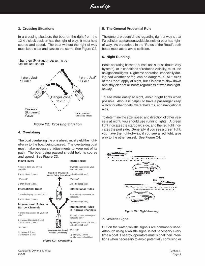
Section CPage 2
Candia FS Owner’s Manual03/00
3. Crossing Situations
In a crossing situation, the boat on the right from the12-4 o’clock position has the right-of-way. It must holdcourse and speed. The boat without the right-of-waymust keep clear and pass to the stern. See Figure C2.
Figure C2: Crossing Situation
4. Overtaking
The boat overtaking the one ahead must yield the right-of-way to the boat being passed. The overtaking boatmust make necessary adjustments to keep out of itspath. The boat being passed should hold its courseand speed. See Figure C3.
Figure C3: Overtaking
5. The General Prudential Rule
The general prudential rule regarding right-of-way is thatif a collision appears unavoidable, neither boat has right-of-way. As prescribed in the “Rules of the Road”, bothboats must act to avoid collision.
6. Night Running
Boats operating between sunset and sunrise (hours varyby state), or in conditions of reduced visibility, must usenavigational lights. Nighttime operation, especially dur-ing bad weather or fog, can be dangerous. All “Rulesof the Road” apply at night, but it is best to slow downand stay clear of all boats regardless of who has right-of-way.
To see more easily at night, avoid bright lights whenpossible. Also, it is helpful to have a passenger keepwatch for other boats, water hazards, and navigationalaids.
To determine the size, speed and direction of other ves-sels at night, you should use running lights. A greenlight indicates the starboard side, and the red light indi-cates the port side. Generally, if you see a green light,you have the right-of-way; if you see a red light, giveway to the other vessel. See Figure C4.
Figure C4: Night Running
7. Whistle Signal
Out on the water, whistle signals are commonly used.Although using a whistle signal is not necessary everytime a boat is nearby, operators must signal their inten-tions when necessary to avoid potentially confusing or
Inland Rules
“I want to pass you on yourport side.
2 short blasts (1 sec.)
“Proceed”
2 short blasts (1 sec.)
International Rules
“I am altering my course to port.”
2 short blasts (1 sec.)
International Rules inNarrow Channels
“I intend to pass you on your portside.”
2 prolonged blasts (4-6 sec.)2 short blasts (1 sec.)
“Proceed.”
1 prolonged, 1 short1 prolonged, 1 short
Inland Rules
“I want to pass you on yourstarboard side.
1 short blast (1 sec.)
“Proceed”
1 short blast (1 sec.)
International Rules
“I am altering my course tostarboard.”
1 short blast (1 sec.)
International Rulesin Narrow Channels
“I intend to pass you on yourstarboard side.”
2 prolonged blasts (4-6 sec.)1 short blast (1 sec.)
“Proceed.”
1 prolonged, 1 short1 prolonged, 1 short blast
Give-way (Burdened)Vessel Overtaking
Stand-on (Privileged)Vessel Being Overtaken
Danger Zone112.5o
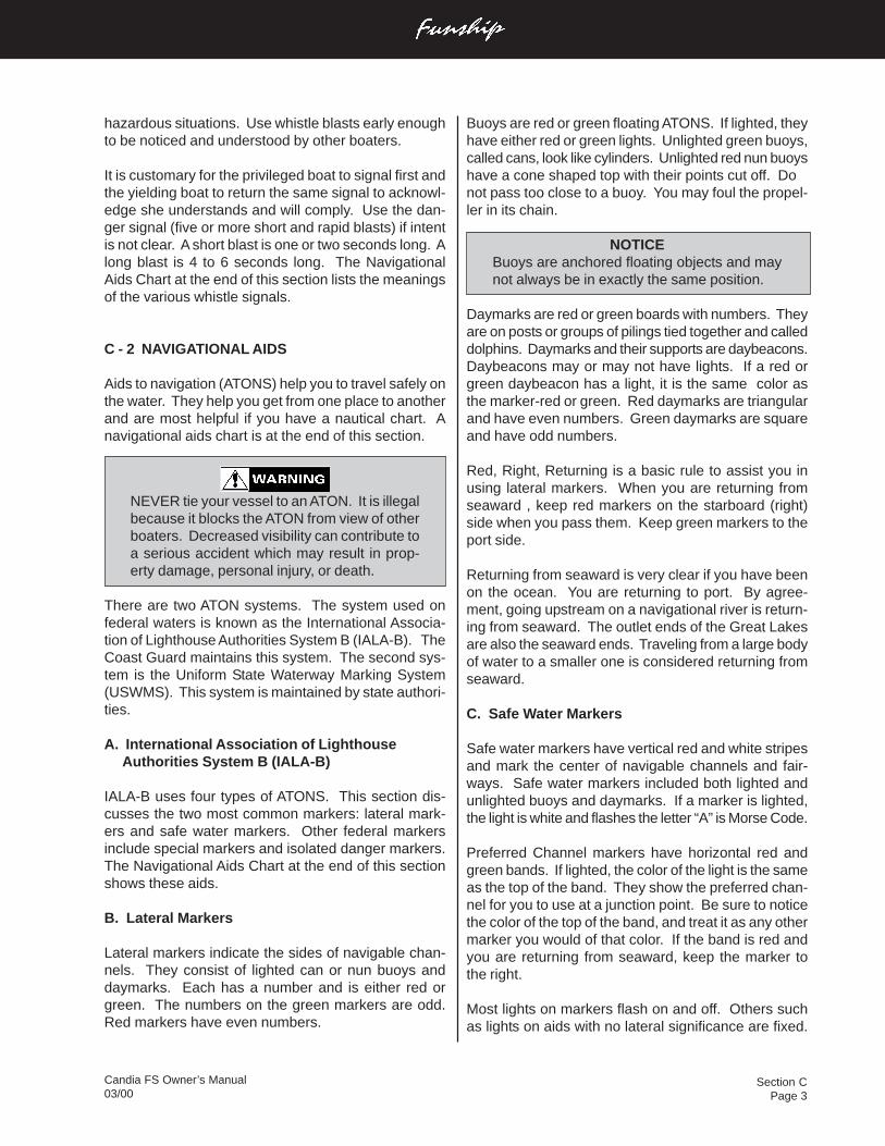
Section CPage 3
Candia FS Owner’s Manual03/00
Buoys are red or green floating ATONS. If lighted, theyhave either red or green lights. Unlighted green buoys,called cans, look like cylinders. Unlighted red nun buoyshave a cone shaped top with their points cut off. Donot pass too close to a buoy. You may foul the propel-ler in its chain.
NOTICEBuoys are anchored floating objects and maynot always be in exactly the same position.
Daymarks are red or green boards with numbers. Theyare on posts or groups of pilings tied together and calleddolphins. Daymarks and their supports are daybeacons.Daybeacons may or may not have lights. If a red orgreen daybeacon has a light, it is the same color asthe marker-red or green. Red daymarks are triangularand have even numbers. Green daymarks are squareand have odd numbers.
Red, Right, Returning is a basic rule to assist you inusing lateral markers. When you are returning fromseaward , keep red markers on the starboard (right)side when you pass them. Keep green markers to theport side.
Returning from seaward is very clear if you have beenon the ocean. You are returning to port. By agree-ment, going upstream on a navigational river is return-ing from seaward. The outlet ends of the Great Lakesare also the seaward ends. Traveling from a large bodyof water to a smaller one is considered returning fromseaward.
C. Safe Water Markers
Safe water markers have vertical red and white stripesand mark the center of navigable channels and fair-ways. Safe water markers included both lighted andunlighted buoys and daymarks. If a marker is lighted,the light is white and flashes the letter “A” is Morse Code.
Preferred Channel markers have horizontal red andgreen bands. If lighted, the color of the light is the sameas the top of the band. They show the preferred chan-nel for you to use at a junction point. Be sure to noticethe color of the top of the band, and treat it as any othermarker you would of that color. If the band is red andyou are returning from seaward, keep the marker tothe right.
Most lights on markers flash on and off. Others suchas lights on aids with no lateral significance are fixed.
hazardous situations. Use whistle blasts early enoughto be noticed and understood by other boaters.
It is customary for the privileged boat to signal first andthe yielding boat to return the same signal to acknowl-edge she understands and will comply. Use the dan-ger signal (five or more short and rapid blasts) if intentis not clear. A short blast is one or two seconds long. Along blast is 4 to 6 seconds long. The NavigationalAids Chart at the end of this section lists the meaningsof the various whistle signals.
C - 2 NAVIGATIONAL AIDS
Aids to navigation (ATONS) help you to travel safely onthe water. They help you get from one place to anotherand are most helpful if you have a nautical chart. Anavigational aids chart is at the end of this section.
NEVER tie your vessel to an ATON. It is illegalbecause it blocks the ATON from view of otherboaters. Decreased visibility can contribute toa serious accident which may result in prop-erty damage, personal injury, or death.
There are two ATON systems. The system used onfederal waters is known as the International Associa-tion of Lighthouse Authorities System B (IALA-B). TheCoast Guard maintains this system. The second sys-tem is the Uniform State Waterway Marking System(USWMS). This system is maintained by state authori-ties.
A. International Association of Lighthouse Authorities System B (IALA-B)
IALA-B uses four types of ATONS. This section dis-cusses the two most common markers: lateral mark-ers and safe water markers. Other federal markersinclude special markers and isolated danger markers.The Navigational Aids Chart at the end of this sectionshows these aids.
B. Lateral Markers
Lateral markers indicate the sides of navigable chan-nels. They consist of lighted can or nun buoys anddaymarks. Each has a number and is either red orgreen. The numbers on the green markers are odd.Red markers have even numbers.
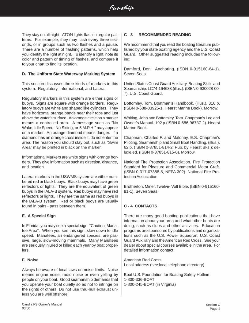
Section CPage 4
Candia FS Owner’s Manual03/00
They stay on all night. ATON lights flash in regular pat-terns. For example, they may flash every three sec-onds, or in groups such as two flashes and a pause.There are a number of flashing patterns, which helpyou identify the light at night. To identify a light, note itscolor and pattern or timing of flashes, and compare itto your chart to find its location.
D. The Uniform State Waterway Marking System
This section discusses three kinds of markers in thissystem: Regulatory, Informational, and Lateral.
Regulatory markers in this system are either signs orbuoys. Signs are square with orange borders. Regu-latory buoys are white and shaped like cylinders. Theyhave horizontal orange bands near their tops and justabove the water’s surface. An orange circle on a markermeans a controlled area. A message such as ”NoWake, Idle Speed, No Skiing, or 5 M.P.H.” may appearon a marker. An orange diamond means danger. If adiamond has an orange cross inside it, do not enter thearea. The reason you should stay out, such as “SwimArea” may be printed in black on the marker.
Informational Markers are white signs with orange bor-ders. They give information such as direction, distance,and location.
Lateral markers in the USWMS system are either num-bered red or black buoys. Black buoys may have greenreflectors or lights. They are the equivalent of greenbuoys in the IALA-B system. Red buoys may have redreflectors or lights. They are the same as red buoys inthe IALA-B system. Red or black buoys are usuallyfound in pairs - pass between them.
E. A Special Sign
In Florida, you may see a special sign: “Caution, Mana-tee Area”. When you see this sign, slow down to idlespeed. Manatees, an endangered species, are pas-sive, large, slow-moving mammals. Many Manateesare seriously injured or killed each year by boat propel-lers.
F. Noise
Always be aware of local laws on noise limits. Noisemeans engine noise, radio noise or even yelling bypeople on your boat. Good seamanship demands thatyou operate your boat quietly so as not to infringe onthe rights of others. Do not use thru-hull exhaust un-less you are well offshore.
C - 3 RECOMMENDED READING
We recommend that you read the boating literature pub-lished by your state boating agency and the U.S. CoastGuard. Other suggested reading includes the follow-ing:
Damford, Don. Anchoring. (ISBN 0-915160-64-1).Seven Seas.
United States Coast Guard Auxiliary. Boating Skills andSeamanship. LC74-164688.(illus.). (ISBN 0-930028-00-7). U.S. Coast Guard.
Bottomley, Tom. Boatman’s Handbook, (illus.). 316 p.(ISBN 0-688-03925-1, Hearst Marine Book). Morrow.
Whiting, John and Bottomley, Tom. Chapman’s Log andOwner’s Manual. 192 p.(ISBN 0-686-96737-2). HearstMarine Book.
Chapman, Charles F. and Maloney, E.S. Chapman’sPiloting, Seamanship and Small Boat Handling. (illus.).62 p. (ISBN 0-87851-814-2, Pub. by Hearst Bks.); de-luxe ed. (ISBN 0-87851-815-0). Morrow.
National Fire Protection Association. Fire ProtectionStandard for Pleasure and Commercial Motor Craft.(ISBN 0-317-07388-5, NFPA 302). National Fire Pro-tection Association.
Brotherton, Miner. Twelve- Volt Bible. (ISBN 0-915160-81-1). Seven Seas.
C - 4 CONTACTS
There are many good boating publications that haveinformation about your area and what other boats aredoing, such as clubs and other activities. Educationprograms are sponsored by publications and organiza-tions such as the U.S. Power Squadron, U.S. CoastGuard Auxiliary and the American Red Cross. See yourdealer about special courses available in the area. Fordetailed information contact:
American Red CrossLocal address (see local telephone directory)
Boat U.S. Foundation for Boating Safety Hotline1-800-336-BOAT1-800-245-BOAT (in Virginia)

Section CPage 5
Candia FS Owner’s Manual03/00
U.S. Coast Guard Info Line1-800-368-5647
NMMA Sources of Waterways Information - NationalMarine Manufacturers Association has five (5) book-lets which list sources for safety, cruising, and local wa-terway information. Each covers a different region ofthe U.S. (North Central, South Central, Northeastern,Southeastern and Western). For single copies, writeSources of Waterways information, NMMA, 401 N.Michigan Avenue, Chicago, Illinois 60611. Ask for thebooklet for your region.
Skippers CourseGPO Superintendent of DocumentsWashington, DC 20012202-512-1800202-512-2250 (fax)
United States Coast Guard AuxiliaryLocal Flotilla or contact appropriate Coast GuardDistrict Headquarters
United States Coast Guard Headquarters2100 2nd St., SWWashington, D.C. 20593-0001202-267-1060
United States Power SquadronP.O. Box 30423Raleigh, NC 27617
C - 5 OWNER’S LOGS AND RECORDS
At the end of this owner’s manual are several formswhich you will find very helpful.
The Float Plan provides a record of your destination,departure and return times, boat description, passen-ger list, and other information about the trip you haveplanned. At the bottom of the form is space for listingemergency telephone numbers in case your return isdelayed past the expected time. It also has space forindicating information about the person filing this re-port. Leave the completed form ashore with a respon-sible person. We recommend you make several cop-ies of this form each boating season to assure an amplesupply.
The Fuel Log is a handy way to record informationcovering engine hours, fuel consumption, miles trav-eled, as well as RPM (revolutions per minute), averageM.P.H. (miles per hour) and GPH (gallons per hour).
The Service/Maintenance Log provides a record ofmaintenance work completed, the date of completion,and the engine hour reading. This log also helps youidentify the frequency of routine maintenance work, suchas engine oil changes. If you should decide to sell yourboat, it demonstrates to perspective buyers that youhave done a good job taking care of it.
The Service Information Sheet allows you to recordall the pertinent information regarding your Four Winns®boat. This sheet will be extremely helpful when order-ing additional/optional parts for your boat or when hav-ing service work done.
C - 6 NAVIGATIONAL AIDS CHART
The illustrated Navigational Aids Charts contain infor-mation concerning whistle signals, storm warnings,bridge signals, and buoy descriptions. See Figure C5and Figure C6 on the following page.
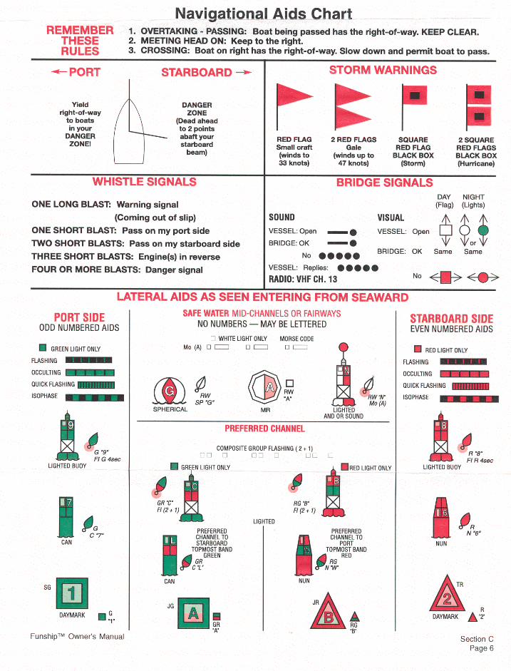
Section DPage 1
Candia FS Owner’s Manual03/00
D - 1 FOUR WINNS® WARRANTY POLICY
The Four Winns® Winning Edge™ Owner Protection Plan,provides the new Four Winns® purchaser with one of themost comprehensive corporate commitments in the ma-rine industry today. The Four Winns® Owner ProtectionPlan, defines the warranty coverage on all units manu-factured by Four Winns®. It thoroughly describes thewarranty policies and those procedures to be followed toobtain warranty coverage. Review the Four Winns® OwnerProtection Plan and limited warranty statements care-fully.
All engines utilized in the Four Winns® product are war-ranted by the engine manufacturer. Your Four Winns®dealer is authorized to repair your engines and will workclosely with the manufacturer to resolve any problemsyou have.
D - 2 HULL STRUCTURE WARRANTY
Each unit manufactured by Four Winns® is encompassedby a separate warranty providing specific coverage on thehull structure. The Four Winns® Owner Protection Planthoroughly describes this coverage.
D - 3 WARRANTY REGISTRATION
A Four Winns® Warranty Registration Card is attachedto the Four Winns® Owner Protection Plan statement.Your Four Winns® Dealer is responsible for completingand mailing the warranty card at the time of purchase.This is the sole basis for establishing proof of ownershipof the boat and corresponding warranty validation.Registration of the boat and engines with the manufac-turer is required by the Federal Boat Safety Act of 1971.
Other equipment manufacturers also require that theirproducts be registered with the respective companies.The warranty registration card is provided in the owner’sinformation packet.
D - 4 TRANSFER OF WARRANTY
Four Winns® confidence in the product and our warrantycommitments can extend after the original purchaser maychoose to move on to a new boat. Four Winns® War-ranty coverage is transferable to successive owners ofthe boat. Registration of the second or successive own-ers is required. The Four Winns® Owner Protection Planthoroughly describes the action required to transfer war-ranty coverage.
D - 5 PRE-OWNED UNIT REGISTRATION
Section B-4 Transfer of Warranty discussed the need toproperly register the purchase of a pre-owned boat withFour Winns® to transfer applicable warranty coverage.
Purchasers of all Pre-Owned Four Winns® models areencouraged to register ownership with Four Winns®. Toregister ownership of a “Pre-Owned Four Winns® boat,”provide Four Winns® with your name, address, daytimephone number, purchase date, and hull serial number ofthe boat purchased.
If you wish to transfer warranty, be sure to include a checkto cover the necessary fee. The amount of the transferfee is $50.00. You can send the check to Four Winns®and we will notify the engine manufacturer, Volvo Penta,of the engine warranty transfer.
The hull serial number plate is permanently affixed to thestarboard side of the transom.
Registration of a Pre-Owned Four Winns® boat does notextend or in any way affect or modify the specific terms ofthe Four Winns® Owner Protection Plan or Limited War-ranties.
We provide this service to the purchasers of Pre-OwnedFour Winns® boats in the interest of better boating. FourWinns® welcomes every purchaser of a Four Winns®boat, new or used, to our family.
WARRANTY AND SERVICE
Section DPage 2
Candia FS Owner’s Manual03/00
D - 6 INSURANCE COVERAGE
One of your responsibilities as a new boat owner is toacquire proper insurance protection. Insurance shouldinclude comprehensive and general liability coverage ap-propriate to your financial needs. Please contact yourlocal agent for assistance on insurance coverage.
D - 7 SERIAL NUMBER RECORD
The manufacturer, model, and serial number of major com-ponents are recorded during the assembly of each FourWinns® boat. Two copies of this completed form areincluded at the end of this section. One copy should beremoved and kept by the dealer in his records. This canassist the dealer in processing warranty claims, or obtain-ing necessary information. The second copy should bekept in this owners manual.
D - 8 PRE-DELIVERY SERVICE
Four Winns® makes every effort to deliver your boat in“turn key” condition to the dealer. The process of trans-porting and handling the boat necessitates certain inspec-tions and adjustments prior to delivery to you. Also, vari-ous aspects of operation must be checked and adjustedimmediately prior to final delivery and use.
The selling Four Winns® dealer must perform this thor-ough review of the boat and its numerous systems duringthe commissioning or “dealer pre-delivery service” of thecraft.
A Four Winns® Pre-Delivery Inspection Form is part ofthe Warranty Registration Card. It lists the many itemsencompassed by the pre-delivery service previously de-scribed. The dealer is to check off the items as they arecompleted, and complete the form as indicated providingspecific performance related information appropriately.
Your Four Winns® dealer will sign the Pre-Delivery In-spection Form of the Warranty Registration Card uponcompletion of the work. You will also be asked to signthe Pre-Delivery Inspection Form upon accepting deliv-ery of the boat. You are to retain the two copies marked“Boat Owner”. Your dealer is to retain the copy marked“Dealer copy” for his records. The Manufacturer’s copyis to be mailed to the Four Winns® Customer ServiceDepartment.
D - 9 REPLACEMENT PARTS
Four Winns® dealers are equipped with a Four Winns®Parts Manual that details the components of each modeland their appropriate part numbers. Many Four Winns®dealers inventory common replacement components.
In addition, Four Winns® maintains specific records onthe components used in the manufacture of each unitand makes a concerted effort to maintain componentsspecifically to fill replacement part needs.
The Four Winns® dealer from whom you purchased yourboat is in the best position to meet your needs. If hedoes not have the needed item, he has the capability,through direct contact with the Four Winns® CustomerService Department, to obtain it quickly. Four Winns®will only sell replacement parts to established FourWinns® dealers. If you relocate and cannot find a FourWinns® dealer close to you, contact the Four Winns®Customer Service Department for information on the near-est dealer in your area.
D - 10 WINNGEAR™
Show your colors! Four Winns® offers a complete line ofsports clothing designed to complement your new boat.Your Four Winns® dealer has a complete catalog andpricing.
Section EPage 1
Candia FS Owner’s Manual03/00
E - 2 ENGINE EXHAUST
The carbon monoxide in exhaust fumes can be hazard-ous. It is important for you and your passengers to beaware of the potential safety hazard created by exhaustfumes. Familiarize yourself with the symptoms of indi-viduals overcome by carbon monoxide, and most im-portantly, ways you can protect yourself and your guests.
DO NOT inhale exhaust fumes! Exhaust con-tains carbon monoxide which is colorless andodorless. Carbon monoxide is a dangerous gasthat is potentially lethal.
Persons overcome by carbon monoxide mayexhibit the following symptoms:
a. Watering and itchy eyesb. Flushed appearancec. Throbbing templesd. Inattentivenesse. Inability to think coherentlyf. Ringing in the earsg. Tightness across the chesth. Headachei. Drowsinessj. Incoherencek. Nauseal. Dizzinessm. Fatiguen. Vomitingo. Collapsep. Convulsions
IF YOU THINK EXHAUST FUMES ARE ENTERINGYOUR BOAT, DETERMINE THE CAUSE AND HAVE ITCORRECTED IMMEDIATELY!
The following suggestions can help prevent exhaustfumes from entering the boat:
1. DO NOT allow the boat to remain stationary withthe engine running for an extended period of time.
E- 1 GENERAL
DO NOT attempt to service any engine with-out being totally familiar with the safe andproper service procedures. Do not attemptto maintain or adjust an engine while it is run-ning. Certain moving parts are exposed andfailing to shut off the engine can result in se-rious injury or death.
Four Winns® does not manufacture engines. Becauseof the technical nature of the engines, all manufac-turers of these items require that warranty and serviceproblems be taken directly to an authorized dealer forresolution. The Four Winns® dealer from whom youpurchased your boat will handle all warranty and ser-vice matters with the engine manufacturer for you.
In compliance with the Federal Boat Safety Act of 1971,all engine manufacturers require their products to beregistered. A registration card is furnished with eachnew engine. When selling a Four Winns® boat, thedealer, along with the purchaser, should complete theinformation requested on these cards and return themto the respective engine manufacturers. Engine reg-istration cards are provided with the engine and willusually be found with the owner’s information packet.
Each manufacturer of the various marine power com-ponents provides an owners information manual withtheir product. This publication is included with thismanual. It is important that you read the manual(s)carefully and become completely familiar with propercare and operation of the engine system. Be sure toread the section on winterization. Replacement costsassociated with frozen engine components are quitesubstantial.
Also review the other sections in this manual, espe-cially Sections I on Fuel Systems, and Section F onControl Systems.
ENGINES AND INSTRUMENTATION
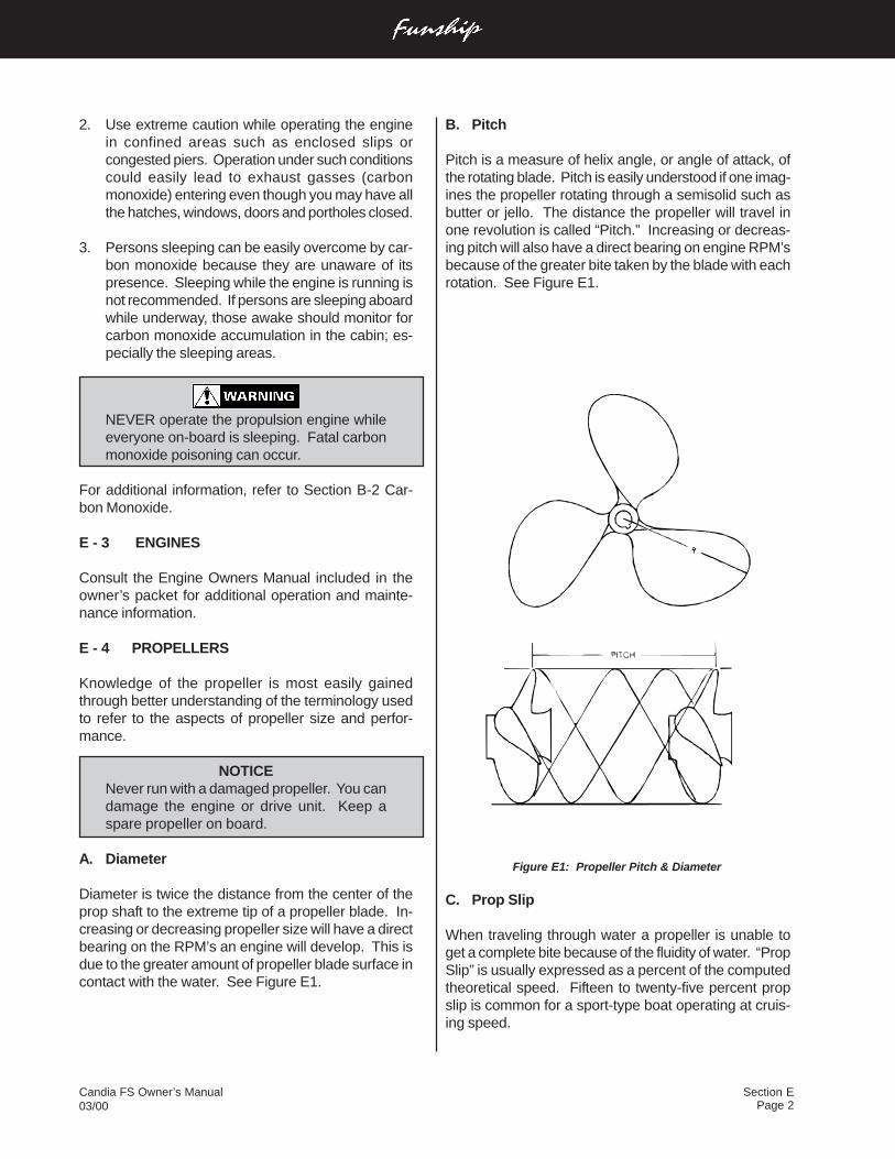
Page 2Candia FS Owner’s Manual03/00
Section E
2. Use extreme caution while operating the enginein confined areas such as enclosed slips orcongested piers. Operation under such conditionscould easily lead to exhaust gasses (carbonmonoxide) entering even though you may have allthe hatches, windows, doors and portholes closed.
3. Persons sleeping can be easily overcome by car-bon monoxide because they are unaware of itspresence. Sleeping while the engine is running isnot recommended. If persons are sleeping aboardwhile underway, those awake should monitor forcarbon monoxide accumulation in the cabin; es-pecially the sleeping areas.
NEVER operate the propulsion engine whileeveryone on-board is sleeping. Fatal carbonmonoxide poisoning can occur.
For additional information, refer to Section B-2 Car-bon Monoxide.
E - 3 ENGINES
Consult the Engine Owners Manual included in theowner’s packet for additional operation and mainte-nance information.
E - 4 PROPELLERS
Knowledge of the propeller is most easily gainedthrough better understanding of the terminology usedto refer to the aspects of propeller size and perfor-mance.
NOTICENever run with a damaged propeller. You candamage the engine or drive unit. Keep aspare propeller on board.
A. Diameter
Diameter is twice the distance from the center of theprop shaft to the extreme tip of a propeller blade. In-creasing or decreasing propeller size will have a directbearing on the RPM’s an engine will develop. This isdue to the greater amount of propeller blade surface incontact with the water. See Figure E1.
B. Pitch
Pitch is a measure of helix angle, or angle of attack, ofthe rotating blade. Pitch is easily understood if one imag-ines the propeller rotating through a semisolid such asbutter or jello. The distance the propeller will travel inone revolution is called “Pitch.” Increasing or decreas-ing pitch will also have a direct bearing on engine RPM’sbecause of the greater bite taken by the blade with eachrotation. See Figure E1.
Figure E1: Propeller Pitch & Diameter
C. Prop Slip
When traveling through water a propeller is unable toget a complete bite because of the fluidity of water. “PropSlip” is usually expressed as a percent of the computedtheoretical speed. Fifteen to twenty-five percent propslip is common for a sport-type boat operating at cruis-ing speed.
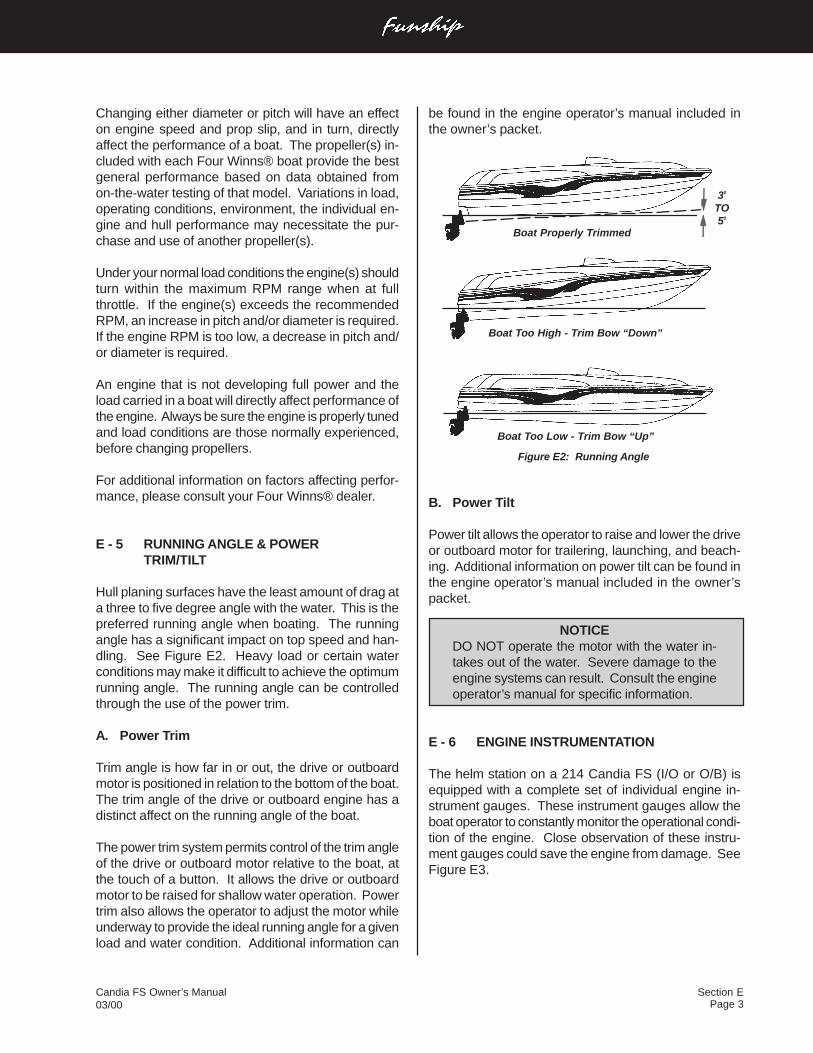
Section EPage 3
Candia FS Owner’s Manual03/00
be found in the engine operator’s manual included inthe owner’s packet.
Figure E2: Running Angle
B. Power Tilt
Power tilt allows the operator to raise and lower the driveor outboard motor for trailering, launching, and beach-ing. Additional information on power tilt can be found inthe engine operator’s manual included in the owner’spacket.
NOTICEDO NOT operate the motor with the water in-takes out of the water. Severe damage to theengine systems can result. Consult the engineoperator’s manual for specific information.
E - 6 ENGINE INSTRUMENTATION
The helm station on a 214 Candia FS (I/O or O/B) isequipped with a complete set of individual engine in-strument gauges. These instrument gauges allow theboat operator to constantly monitor the operational condi-tion of the engine. Close observation of these instru-ment gauges could save the engine from damage. SeeFigure E3.
Changing either diameter or pitch will have an effecton engine speed and prop slip, and in turn, directlyaffect the performance of a boat. The propeller(s) in-cluded with each Four Winns® boat provide the bestgeneral performance based on data obtained fromon-the-water testing of that model. Variations in load,operating conditions, environment, the individual en-gine and hull performance may necessitate the pur-chase and use of another propeller(s).
Under your normal load conditions the engine(s) shouldturn within the maximum RPM range when at fullthrottle. If the engine(s) exceeds the recommendedRPM, an increase in pitch and/or diameter is required.If the engine RPM is too low, a decrease in pitch and/or diameter is required.
An engine that is not developing full power and theload carried in a boat will directly affect performance ofthe engine. Always be sure the engine is properly tunedand load conditions are those normally experienced,before changing propellers.
For additional information on factors affecting perfor-mance, please consult your Four Winns® dealer.
E - 5 RUNNING ANGLE & POWERTRIM/TILT
Hull planing surfaces have the least amount of drag ata three to five degree angle with the water. This is thepreferred running angle when boating. The runningangle has a significant impact on top speed and han-dling. See Figure E2. Heavy load or certain waterconditions may make it difficult to achieve the optimumrunning angle. The running angle can be controlledthrough the use of the power trim.
A. Power Trim
Trim angle is how far in or out, the drive or outboardmotor is positioned in relation to the bottom of the boat.The trim angle of the drive or outboard engine has adistinct affect on the running angle of the boat.
The power trim system permits control of the trim angleof the drive or outboard motor relative to the boat, atthe touch of a button. It allows the drive or outboardmotor to be raised for shallow water operation. Powertrim also allows the operator to adjust the motor whileunderway to provide the ideal running angle for a givenload and water condition. Additional information can
30
TO50
Boat Properly Trimmed
Boat Too High - Trim Bow “Down”
Boat Too Low - Trim Bow “Up”
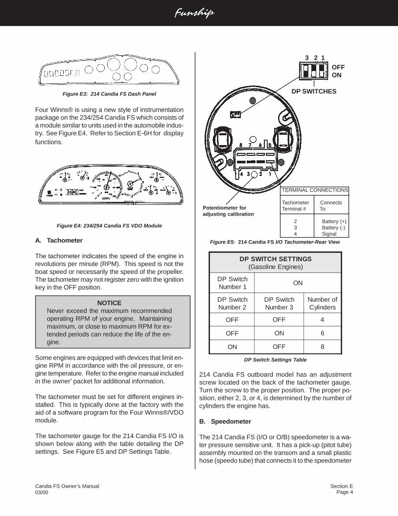
Page 4Candia FS Owner’s Manual03/00
Section E
Figure E5: 214 Candia FS I/O Tachometer-Rear View
DP Switch Settings Table
214 Candia FS outboard model has an adjustmentscrew located on the back of the tachometer gauge.Turn the screw to the proper position. The proper po-sition, either 2, 3, or 4, is determined by the number ofcylinders the engine has.
B. Speedometer
The 214 Candia FS (I/O or O/B) speedometer is a wa-ter pressure sensitive unit. It has a pick-up (pitot tube)assembly mounted on the transom and a small plastichose (speedo tube) that connects it to the speedometer
SGNITTESHCTIWSPD)senignEenilosaG(
hctiwSPD1rebmuN
NO
hctiwSPD2rebmuN
hctiwSPD3rebmuN
forebmuNsrednilyC
FFO FFO 4
FFO NO 6
NO FFO 8
Figure E3: 214 Candia FS Dash Panel
Four Winns® is using a new style of instrumentationpackage on the 234/254 Candia FS which consists ofa module similar to units used in the automobile indus-try. See Figure E4. Refer to Section E-6H for displayfunctions.
Figure E4: 234/254 Candia FS VDO Module
A. Tachometer
The tachometer indicates the speed of the engine inrevolutions per minute (RPM). This speed is not theboat speed or necessarily the speed of the propeller.The tachometer may not register zero with the ignitionkey in the OFF position.
NOTICENever exceed the maximum recommendedoperating RPM of your engine. Maintainingmaximum, or close to maximum RPM for ex-tended periods can reduce the life of the en-gine.
Some engines are equipped with devices that limit en-gine RPM in accordance with the oil pressure, or en-gine temperature. Refer to the engine manual includedin the owner’ packet for additional information.
The tachometer must be set for different engines in-stalled. This is typically done at the factory with theaid of a software program for the Four Winns®/VDOmodule.
The tachometer gauge for the 214 Candia FS I/O isshown below along with the table detailing the DPsettings. See Figure E5 and DP Settings Table.
TERMINAL CONNECTIONS
Tachometer ConnectsTerminal # To:
2 Battery (+) 3 Battery (-) 4 Signal
Potentiometer foradjusting calibration
3 2 1OFFON
DP SWITCHES
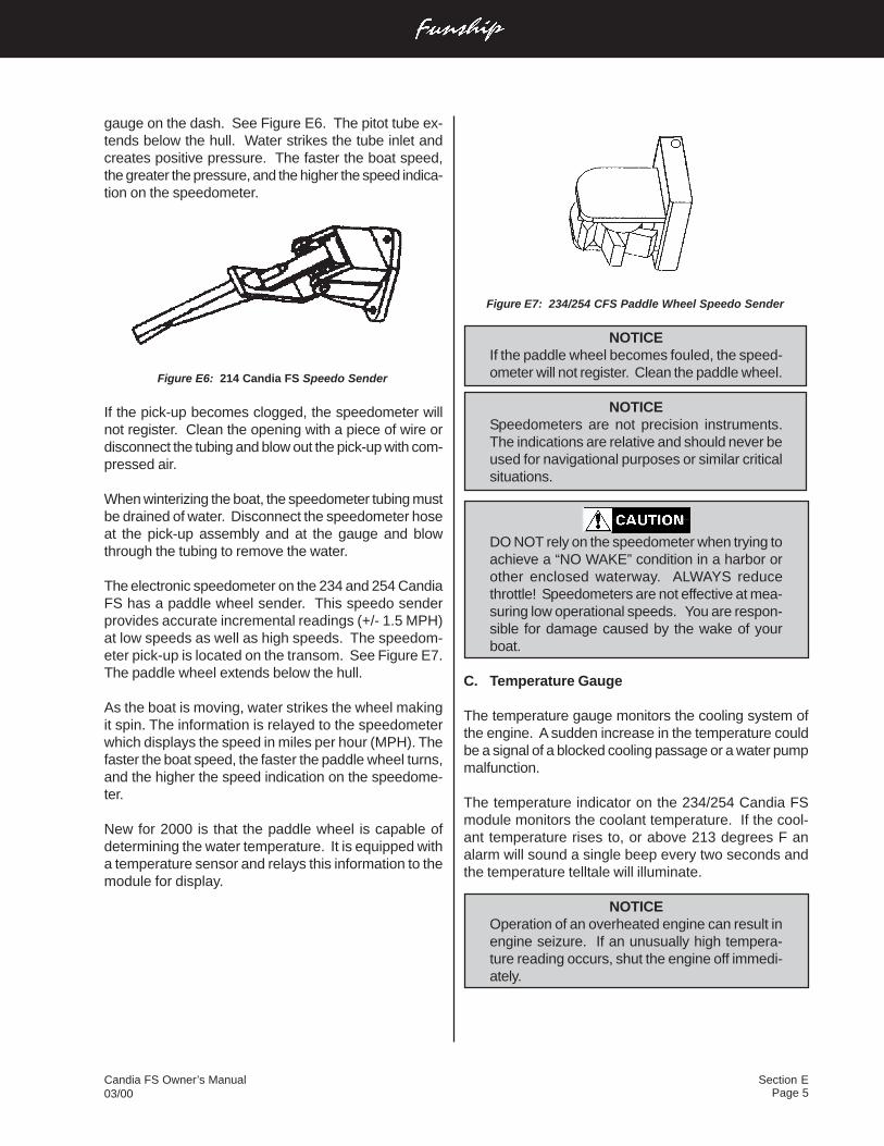
Section EPage 5
Candia FS Owner’s Manual03/00
gauge on the dash. See Figure E6. The pitot tube ex-tends below the hull. Water strikes the tube inlet andcreates positive pressure. The faster the boat speed,the greater the pressure, and the higher the speed indica-tion on the speedometer.
Figure E6: 214 Candia FS Speedo Sender
If the pick-up becomes clogged, the speedometer willnot register. Clean the opening with a piece of wire ordisconnect the tubing and blow out the pick-up with com-pressed air.
When winterizing the boat, the speedometer tubing mustbe drained of water. Disconnect the speedometer hoseat the pick-up assembly and at the gauge and blowthrough the tubing to remove the water.
The electronic speedometer on the 234 and 254 CandiaFS has a paddle wheel sender. This speedo senderprovides accurate incremental readings (+/- 1.5 MPH)at low speeds as well as high speeds. The speedom-eter pick-up is located on the transom. See Figure E7.The paddle wheel extends below the hull.
As the boat is moving, water strikes the wheel makingit spin. The information is relayed to the speedometerwhich displays the speed in miles per hour (MPH). Thefaster the boat speed, the faster the paddle wheel turns,and the higher the speed indication on the speedome-ter.
New for 2000 is that the paddle wheel is capable ofdetermining the water temperature. It is equipped witha temperature sensor and relays this information to themodule for display.
Figure E7: 234/254 CFS Paddle Wheel Speedo Sender
NOTICEIf the paddle wheel becomes fouled, the speed-ometer will not register. Clean the paddle wheel.
NOTICESpeedometers are not precision instruments.The indications are relative and should never beused for navigational purposes or similar criticalsituations.
DO NOT rely on the speedometer when trying toachieve a “NO WAKE” condition in a harbor orother enclosed waterway. ALWAYS reducethrottle! Speedometers are not effective at mea-suring low operational speeds. You are respon-sible for damage caused by the wake of yourboat.
C. Temperature Gauge
The temperature gauge monitors the cooling system ofthe engine. A sudden increase in the temperature couldbe a signal of a blocked cooling passage or a water pumpmalfunction.
The temperature indicator on the 234/254 Candia FSmodule monitors the coolant temperature. If the cool-ant temperature rises to, or above 213 degrees F analarm will sound a single beep every two seconds andthe temperature telltale will illuminate.
NOTICEOperation of an overheated engine can result inengine seizure. If an unusually high tempera-ture reading occurs, shut the engine off immedi-ately.
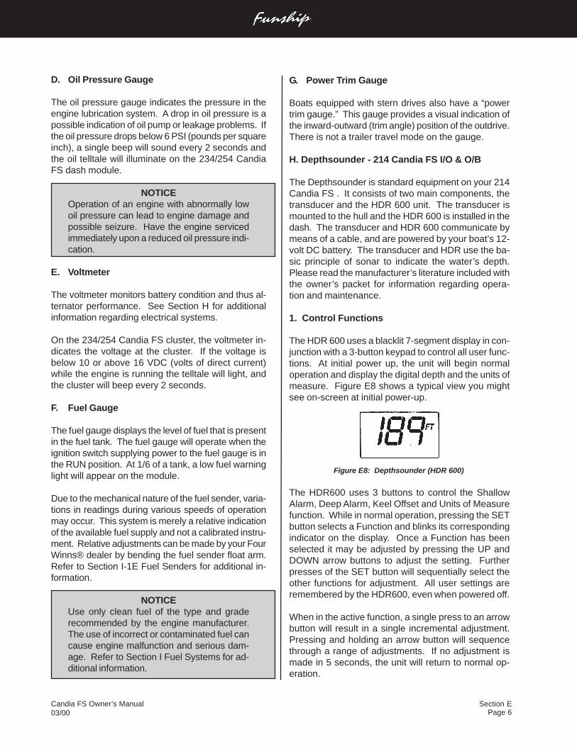
Page 6Candia FS Owner’s Manual03/00
Section E
D. Oil Pressure Gauge
The oil pressure gauge indicates the pressure in theengine lubrication system. A drop in oil pressure is apossible indication of oil pump or leakage problems. Ifthe oil pressure drops below 6 PSI (pounds per squareinch), a single beep will sound every 2 seconds andthe oil telltale will illuminate on the 234/254 CandiaFS dash module.
NOTICEOperation of an engine with abnormally lowoil pressure can lead to engine damage andpossible seizure. Have the engine servicedimmediately upon a reduced oil pressure indi-cation.
E. Voltmeter
The voltmeter monitors battery condition and thus al-ternator performance. See Section H for additionalinformation regarding electrical systems.
On the 234/254 Candia FS cluster, the voltmeter in-dicates the voltage at the cluster. If the voltage isbelow 10 or above 16 VDC (volts of direct current)while the engine is running the telltale will light, andthe cluster will beep every 2 seconds.
F. Fuel Gauge
The fuel gauge displays the level of fuel that is presentin the fuel tank. The fuel gauge will operate when theignition switch supplying power to the fuel gauge is inthe RUN position. At 1/6 of a tank, a low fuel warninglight will appear on the module.
Due to the mechanical nature of the fuel sender, varia-tions in readings during various speeds of operationmay occur. This system is merely a relative indicationof the available fuel supply and not a calibrated instru-ment. Relative adjustments can be made by your FourWinns® dealer by bending the fuel sender float arm.Refer to Section I-1E Fuel Senders for additional in-formation.
NOTICEUse only clean fuel of the type and graderecommended by the engine manufacturer.The use of incorrect or contaminated fuel cancause engine malfunction and serious dam-age. Refer to Section I Fuel Systems for ad-ditional information.
G. Power Trim Gauge
Boats equipped with stern drives also have a “powertrim gauge.” This gauge provides a visual indication ofthe inward-outward (trim angle) position of the outdrive.There is not a trailer travel mode on the gauge.
H. Depthsounder - 214 Candia FS I/O & O/B
The Depthsounder is standard equipment on your 214Candia FS . It consists of two main components, thetransducer and the HDR 600 unit. The transducer ismounted to the hull and the HDR 600 is installed in thedash. The transducer and HDR 600 communicate bymeans of a cable, and are powered by your boat’s 12-volt DC battery. The transducer and HDR use the ba-sic principle of sonar to indicate the water’s depth.Please read the manufacturer’s literature included withthe owner’s packet for information regarding opera-tion and maintenance.
1. Control Functions
The HDR 600 uses a blacklit 7-segment display in con-junction with a 3-button keypad to control all user func-tions. At initial power up, the unit will begin normaloperation and display the digital depth and the units ofmeasure. Figure E8 shows a typical view you mightsee on-screen at initial power-up.
Figure E8: Depthsounder (HDR 600)
The HDR600 uses 3 buttons to control the ShallowAlarm, Deep Alarm, Keel Offset and Units of Measurefunction. While in normal operation, pressing the SETbutton selects a Function and blinks its correspondingindicator on the display. Once a Function has beenselected it may be adjusted by pressing the UP andDOWN arrow buttons to adjust the setting. Furtherpresses of the SET button will sequentially select theother functions for adjustment. All user settings areremembered by the HDR600, even when powered off.
When in the active function, a single press to an arrowbutton will result in a single incremental adjustment.Pressing and holding an arrow button will sequencethrough a range of adjustments. If no adjustment ismade in 5 seconds, the unit will return to normal op-eration.
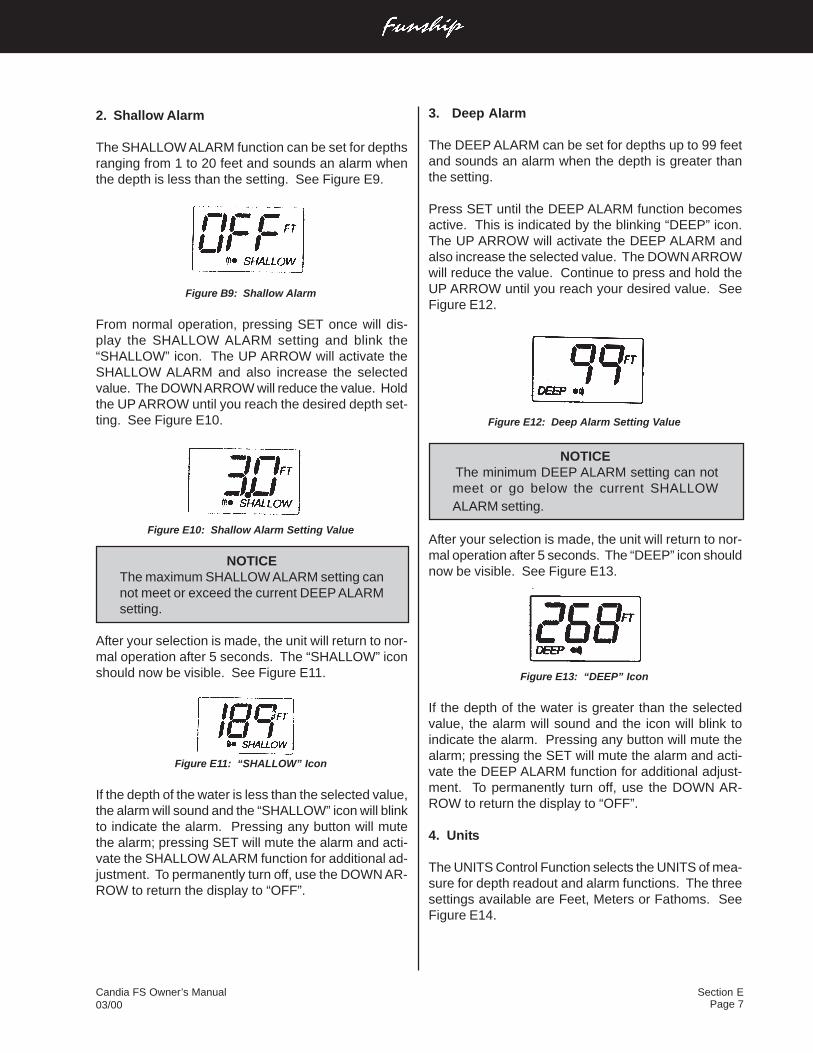
Section EPage 7
Candia FS Owner’s Manual03/00
2. Shallow Alarm
The SHALLOW ALARM function can be set for depthsranging from 1 to 20 feet and sounds an alarm whenthe depth is less than the setting. See Figure E9.
Figure B9: Shallow Alarm
From normal operation, pressing SET once will dis-play the SHALLOW ALARM setting and blink the“SHALLOW” icon. The UP ARROW will activate theSHALLOW ALARM and also increase the selectedvalue. The DOWN ARROW will reduce the value. Holdthe UP ARROW until you reach the desired depth set-ting. See Figure E10.
Figure E10: Shallow Alarm Setting Value
NOTICEThe maximum SHALLOW ALARM setting cannot meet or exceed the current DEEP ALARMsetting.
After your selection is made, the unit will return to nor-mal operation after 5 seconds. The “SHALLOW” iconshould now be visible. See Figure E11.
Figure E11: “SHALLOW” Icon
If the depth of the water is less than the selected value,the alarm will sound and the “SHALLOW” icon will blinkto indicate the alarm. Pressing any button will mutethe alarm; pressing SET will mute the alarm and acti-vate the SHALLOW ALARM function for additional ad-justment. To permanently turn off, use the DOWN AR-ROW to return the display to “OFF”.
3. Deep Alarm
The DEEP ALARM can be set for depths up to 99 feetand sounds an alarm when the depth is greater thanthe setting.
Press SET until the DEEP ALARM function becomesactive. This is indicated by the blinking “DEEP” icon.The UP ARROW will activate the DEEP ALARM andalso increase the selected value. The DOWN ARROWwill reduce the value. Continue to press and hold theUP ARROW until you reach your desired value. SeeFigure E12.
Figure E12: Deep Alarm Setting Value
NOTICEThe minimum DEEP ALARM setting can notmeet or go below the current SHALLOWALARM setting.
After your selection is made, the unit will return to nor-mal operation after 5 seconds. The “DEEP” icon shouldnow be visible. See Figure E13.
Figure E13: “DEEP” Icon
If the depth of the water is greater than the selectedvalue, the alarm will sound and the icon will blink toindicate the alarm. Pressing any button will mute thealarm; pressing the SET will mute the alarm and acti-vate the DEEP ALARM function for additional adjust-ment. To permanently turn off, use the DOWN AR-ROW to return the display to “OFF”.
4. Units
The UNITS Control Function selects the UNITS of mea-sure for depth readout and alarm functions. The threesettings available are Feet, Meters or Fathoms. SeeFigure E14.
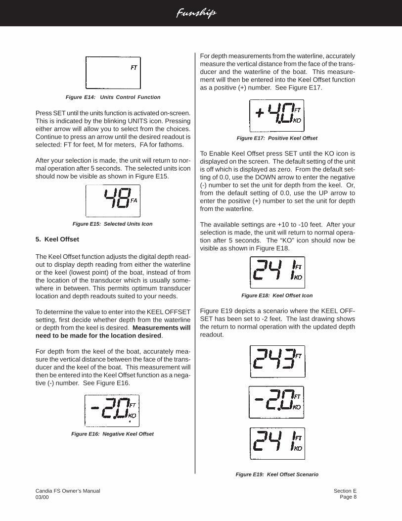
Page 8Candia FS Owner’s Manual03/00
Section E
For depth measurements from the waterline, accuratelymeasure the vertical distance from the face of the trans-ducer and the waterline of the boat. This measure-ment will then be entered into the Keel Offset functionas a positive (+) number. See Figure E17.
Figure E17: Positive Keel Offset
To Enable Keel Offset press SET until the KO icon isdisplayed on the screen. The default setting of the unitis off which is displayed as zero. From the default set-ting of 0.0, use the DOWN arrow to enter the negative(-) number to set the unit for depth from the keel. Or,from the default setting of 0.0, use the UP arrow toenter the positive (+) number to set the unit for depthfrom the waterline.
The available settings are +10 to -10 feet. After yourselection is made, the unit will return to normal opera-tion after 5 seconds. The “KO” icon should now bevisible as shown in Figure E18.
Figure E18: Keel Offset Icon
Figure E19 depicts a scenario where the KEEL OFF-SET has been set to -2 feet. The last drawing showsthe return to normal operation with the updated depthreadout.
Figure E19: Keel Offset Scenario
Figure E14: Units Control Function
Press SET until the units function is activated on-screen.This is indicated by the blinking UNITS icon. Pressingeither arrow will allow you to select from the choices.Continue to press an arrow until the desired readout isselected: FT for feet, M for meters, FA for fathoms.
After your selection is made, the unit will return to nor-mal operation after 5 seconds. The selected units iconshould now be visible as shown in Figure E15.
Figure E15: Selected Units Icon
5. Keel Offset
The Keel Offset function adjusts the digital depth read-out to display depth reading from either the waterlineor the keel (lowest point) of the boat, instead of fromthe location of the transducer which is usually some-where in between. This permits optimum transducerlocation and depth readouts suited to your needs.
To determine the value to enter into the KEEL OFFSETsetting, first decide whether depth from the waterlineor depth from the keel is desired. Measurements willneed to be made for the location desired.
For depth from the keel of the boat, accurately mea-sure the vertical distance between the face of the trans-ducer and the keel of the boat. This measurement willthen be entered into the Keel Offset function as a nega-tive (-) number. See Figure E16.
Figure E16: Negative Keel Offset
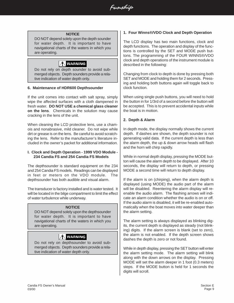
Section EPage 9
Candia FS Owner’s Manual03/00
1. Four Winns®/VDO Clock and Depth Operation
The LCD display has two main functions, clock anddepth functions. The operation and display of the func-tions is controlled by the SET and MODE push but-tons. The programming of the FOUR WINNS®/VDOclock and depth operations of the instrument module isdescribed in the following:
Changing from clock to depth is done by pressing bothSET and MODE and holding them for 2 seconds. Press-ing and holding both buttons again will toggle back toclock function.
When using single push buttons, you will need to holdthe button in for 1/3rd of a second before the button willbe accepted. This is to prevent accidental inputs whilethe boat is in motion.
2. Depth & Alarm
In depth mode, the display normally shows the currentdepth. If dashes are shown, the depth sounder is notgenerating valid data. If the current depth is less thanthe alarm depth, the up & down arrow heads will flashand the horn will chirp rapidly.
While in normal depth display, pressing the MODE but-ton will cause the alarm depth to be displayed. After 10seconds, the display will return to depth, or pressingMODE a second time will return to depth display.
If the alarm is on (chirping), when the alarm depth isdisplayed (using MODE) the audio part of the alarmwill be disabled. Reentering the alarm display will re-enable the audio alarm. The flashing arrows will indi-cate an alarm condition whether the audio is on or off.If the audio alarm is disabled, it will be re-enabled auto-matically when the boat moves into water deeper thanthe alarm setting.
The alarm setting is always displayed as blinking dig-its, the current depth is displayed as steady (not blink-ing) digits. If the alarm screen is blank (set to zero),the alarm is not enabled. If the depth screen showsdashes the depth is zero or not found.
While in depth display, pressing the SET button will enterthe alarm setting mode. The alarm setting will blinkalong with the down arrows on the display. PressingMODE will set the alarm deeper in 1 foot (0.3 meters)steps. If the MODE button is held for 1 seconds thedigits will scroll.
NOTICEDO NOT depend solely upon the depth sounderfor water depth. It is important to havenavigational charts of the waters in which youare operating.
Do not rely on depth sounder to avoid sub-merged objects. Depth sounders provide a rela-tive indication of water depth only.
6. Maintenance of HDR600 Depthsounder
If the unit comes into contact with salt spray, simplywipe the affected surfaces with a cloth dampened infresh water. DO NOT USE a chemical glass cleaneron the lens. Chemicals in the solution may causecracking in the lens of the unit.
When cleaning the LCD protective lens, use a cham-ois and nonabrasive, mild cleaner. Do not wipe whiledirt or grease is on the lens. Be careful to avoid scratch-ing the lens. Refer to the manufacturer’s literature in-cluded in the owner’s packet for additional information.
I. Clock and Depth Operation - 1999 VDO Module -234 Candia FS and 254 Candia FS Models
The depthsounder is standard equipment on the 234and 254 Candia FS models. Readings can be displayedin feet or meters on the VDO module. Thedepthsounder has both audible and visual alarm.
The transducer is factory installed and is water tested. Itwill be located in the bilge compartment to limit the effectof water turbulence while underway.
NOTICEDO NOT depend solely upon the depthsounderfor water depth. It is important to havenavigational charts of the waters in which youare operating.
Do not rely on depthsounder to avoid sub-merged objects. Depth sounders provide a rela-tive indication of water depth only.
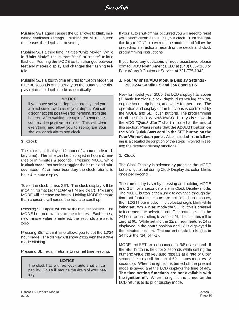
Page 10Candia FS Owner’s Manual03/00
Section E
Pushing SET again causes the up arrows to blink, indi-cating shallower settings. Pushing the MODE buttondecreases the depth alarm setting.
Pushing SET a third time initiates “Units Mode”. Whilein “Units Mode”, the current “feet” or “meter” telltaleflashes. Pushing the MODE button changes betweenfeet and meters display and changes the flashing tell-tale.
Pushing SET a fourth time returns to “Depth Mode”, orafter 30 seconds of no activity on the buttons, the dis-play returns to depth mode automatically.
NOTICE If you have set your depth incorrectly and you
are not sure how to reset your depth. You candisconnect the positive (red) terminal from thebattery. After waiting a couple of seconds re-connect the positive terminal. This will cleareverything and allow you to reprogram yourshallow depth alarm and clock
3. Clock
The clock can display in 12 hour or 24 hour mode (mili-tary time). The time can be displayed in hours & min-utes or in minutes & seconds. Pressing MODE whilein clock mode (not setting) toggles the hr-min and min-sec mode. At an hour boundary the clock returns tohour & minute display.
To set the clock, press SET. The clock display will bein 24 hr. format (so that AM & PM are clear). PressingMODE will increase the hours. Holding MODE for morethan a second will cause the hours to scroll up.
Pressing SET again will cause the minutes to blink. TheMODE button now acts on the minutes. Each time anew minute value is entered, the seconds are set tozero.
Pressing SET a third time allows you to set the 12/24hour mode. The display will show 24:12 with the activemode blinking.
Pressing SET again returns to normal time keeping.
NOTICEThe clock has a three week auto shut-off ca-pability. This will reduce the drain of your bat-tery.
If your auto shut-off has occurred you will need to resetyour alarm depth as well as your clock. Turn the igni-tion key to “ON” to power up the module and follow thepreceding instructions regarding the depth and clockprogramming instructions.
If you have any questions or need assistance pleasecontact VDO North America LLC at (540) 665-0100 orFour Winns® Customer Service at 231-775-1343.
J. Four Winns®/VDO Module Display Settings -2000 234 Candia FS and 254 Candia FS
New for model year 2000, the LCD display has seven(7) basic functions, clock, depth, distance log, trip log,engine hours, trip hours, and water temperature. Theoperation and display of the functions is controlled bythe MODE and SET push buttons. The programmingof all the FOUR WINNS®/VDO displays is shown inthe VDO “Quick Start” chart included at the end ofthis section. Please note that the ADJUST button onthe VDO Quick Start card is the SET button on theFour Winns® dash panel. Also included in the follow-ing is a detailed description of the steps involved in set-ting the different display functions:
1. Clock
The Clock Display is selected by pressing the MODEbutton. Note that during Clock Display the colon blinksonce per second.
The time of day is set by pressing and holding MODEand SET for 2 seconds while in Clock Display mode.The MODE button is then used to advance through thetime set features. Hours are set first, then minutes,then 12/24 hour mode. The selected digits blink whilebeing set. While in set mode the SET button is pressedto increment the selected unit. The hours is set in the24 hour format, rolling to zero at 24. The minutes roll tozero at 60. While setting the 12/24 hour feature, 24 isdisplayed in the hours position and 12 is displayed inthe minutes position. The current mode blinks (i.e. in24 hour the “24” blinks).
MODE and SET are debounced for 3/8 of a second. Ifthe SET button is held for 2 seconds while setting thenumeric value the key auto repeats at a rate of 6 persecond (i.e. to scroll through all 60 minutes requires 12seconds). When the ignition is turned off the presentmode is saved and the LCD displays the time of day.The time setting functions are not available withthe ignition off. When the ignition is turned on theLCD returns to its prior display mode.
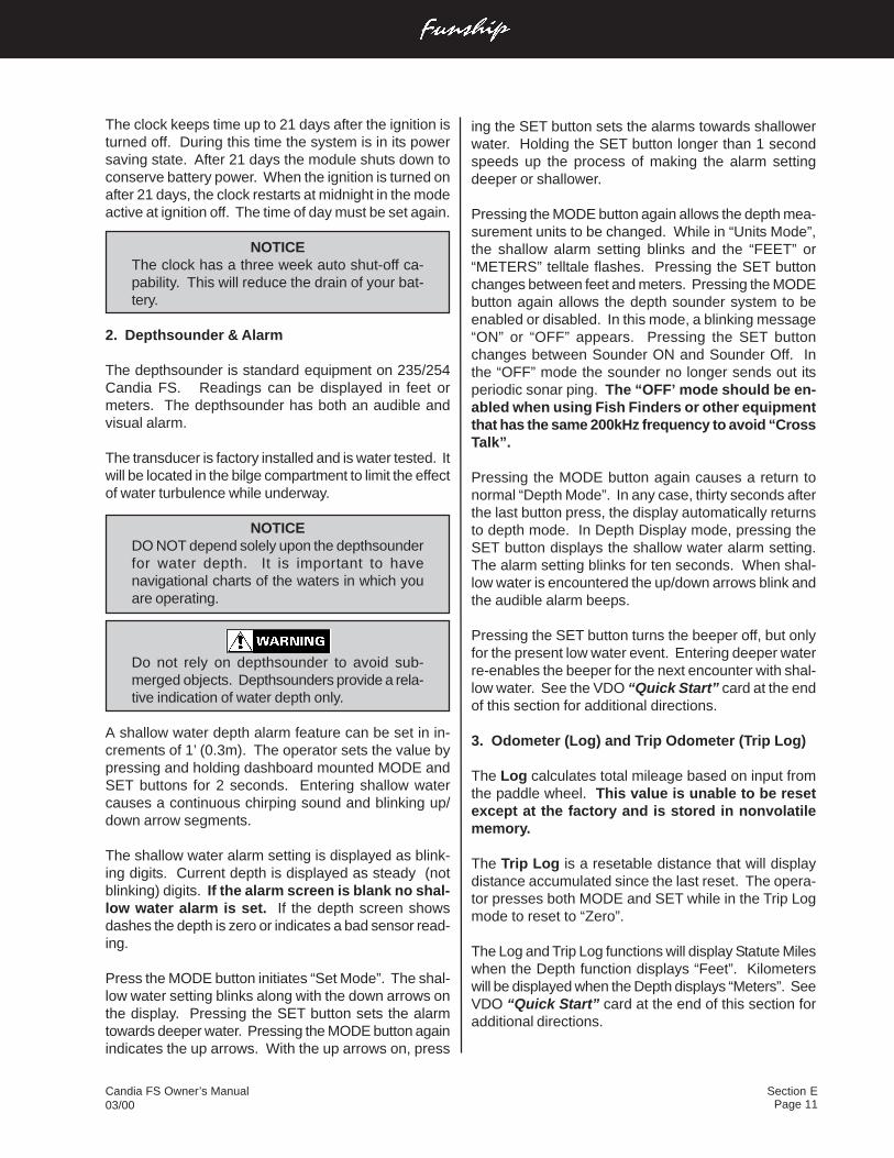
Section EPage 11
Candia FS Owner’s Manual03/00
ing the SET button sets the alarms towards shallowerwater. Holding the SET button longer than 1 secondspeeds up the process of making the alarm settingdeeper or shallower.
Pressing the MODE button again allows the depth mea-surement units to be changed. While in “Units Mode”,the shallow alarm setting blinks and the “FEET” or“METERS” telltale flashes. Pressing the SET buttonchanges between feet and meters. Pressing the MODEbutton again allows the depth sounder system to beenabled or disabled. In this mode, a blinking message“ON” or “OFF” appears. Pressing the SET buttonchanges between Sounder ON and Sounder Off. Inthe “OFF” mode the sounder no longer sends out itsperiodic sonar ping. The “OFF’ mode should be en-abled when using Fish Finders or other equipmentthat has the same 200kHz frequency to avoid “CrossTalk”.
Pressing the MODE button again causes a return tonormal “Depth Mode”. In any case, thirty seconds afterthe last button press, the display automatically returnsto depth mode. In Depth Display mode, pressing theSET button displays the shallow water alarm setting.The alarm setting blinks for ten seconds. When shal-low water is encountered the up/down arrows blink andthe audible alarm beeps.
Pressing the SET button turns the beeper off, but onlyfor the present low water event. Entering deeper waterre-enables the beeper for the next encounter with shal-low water. See the VDO “Quick Start” card at the endof this section for additional directions.
3. Odometer (Log) and Trip Odometer (Trip Log)
The Log calculates total mileage based on input fromthe paddle wheel. This value is unable to be resetexcept at the factory and is stored in nonvolatilememory.
The Trip Log is a resetable distance that will displaydistance accumulated since the last reset. The opera-tor presses both MODE and SET while in the Trip Logmode to reset to “Zero”.
The Log and Trip Log functions will display Statute Mileswhen the Depth function displays “Feet”. Kilometerswill be displayed when the Depth displays “Meters”. SeeVDO “Quick Start” card at the end of this section foradditional directions.
The clock keeps time up to 21 days after the ignition isturned off. During this time the system is in its powersaving state. After 21 days the module shuts down toconserve battery power. When the ignition is turned onafter 21 days, the clock restarts at midnight in the modeactive at ignition off. The time of day must be set again.
NOTICEThe clock has a three week auto shut-off ca-pability. This will reduce the drain of your bat-tery.
2. Depthsounder & Alarm
The depthsounder is standard equipment on 235/254Candia FS. Readings can be displayed in feet ormeters. The depthsounder has both an audible andvisual alarm.
The transducer is factory installed and is water tested. Itwill be located in the bilge compartment to limit the effectof water turbulence while underway.
NOTICEDO NOT depend solely upon the depthsounderfor water depth. It is important to havenavigational charts of the waters in which youare operating.
Do not rely on depthsounder to avoid sub-merged objects. Depthsounders provide a rela-tive indication of water depth only.
A shallow water depth alarm feature can be set in in-crements of 1’ (0.3m). The operator sets the value bypressing and holding dashboard mounted MODE andSET buttons for 2 seconds. Entering shallow watercauses a continuous chirping sound and blinking up/down arrow segments.
The shallow water alarm setting is displayed as blink-ing digits. Current depth is displayed as steady (notblinking) digits. If the alarm screen is blank no shal-low water alarm is set. If the depth screen showsdashes the depth is zero or indicates a bad sensor read-ing.
Press the MODE button initiates “Set Mode”. The shal-low water setting blinks along with the down arrows onthe display. Pressing the SET button sets the alarmtowards deeper water. Pressing the MODE button againindicates the up arrows. With the up arrows on, press
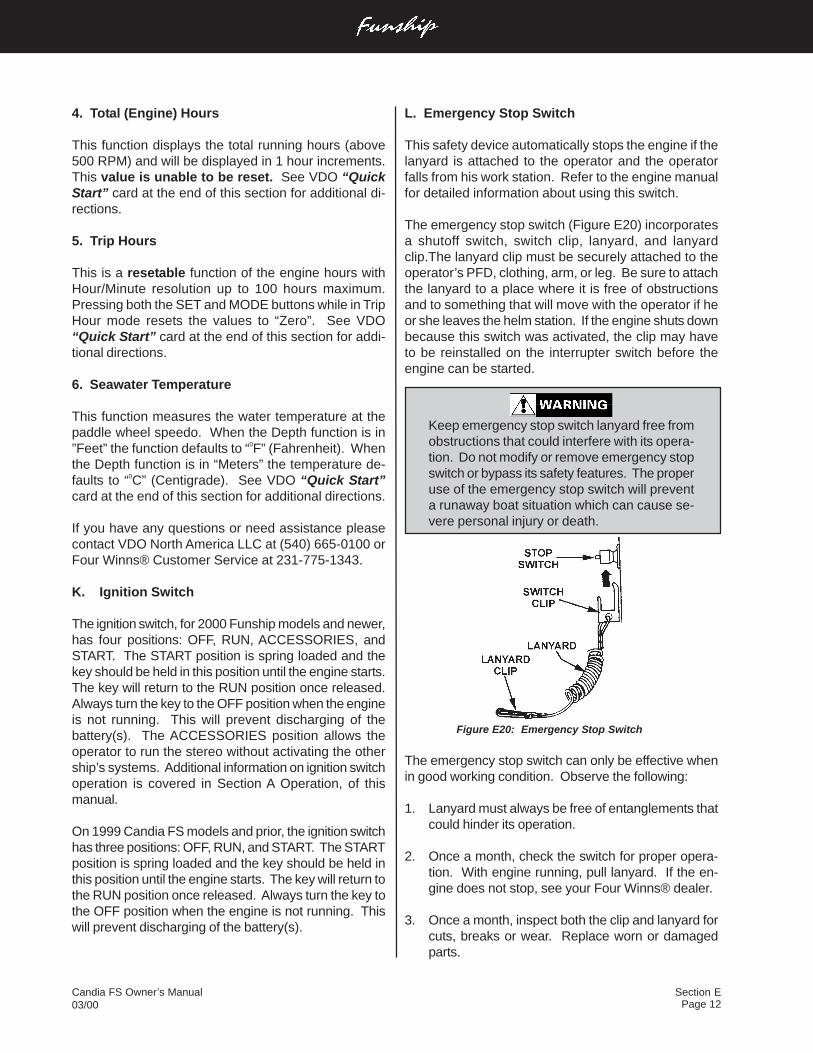
Page 12Candia FS Owner’s Manual03/00
Section E
Keep emergency stop switch lanyard free fromobstructions that could interfere with its opera-tion. Do not modify or remove emergency stopswitch or bypass its safety features. The properuse of the emergency stop switch will preventa runaway boat situation which can cause se-vere personal injury or death.
Figure E20: Emergency Stop Switch
The emergency stop switch can only be effective whenin good working condition. Observe the following:
1. Lanyard must always be free of entanglements thatcould hinder its operation.
2. Once a month, check the switch for proper opera-tion. With engine running, pull lanyard. If the en-gine does not stop, see your Four Winns® dealer.
3. Once a month, inspect both the clip and lanyard forcuts, breaks or wear. Replace worn or damagedparts.
4. Total (Engine) Hours
This function displays the total running hours (above500 RPM) and will be displayed in 1 hour increments.This value is unable to be reset. See VDO “QuickStart” card at the end of this section for additional di-rections.
5. Trip Hours
This is a resetable function of the engine hours withHour/Minute resolution up to 100 hours maximum.Pressing both the SET and MODE buttons while in TripHour mode resets the values to “Zero”. See VDO“Quick Start” card at the end of this section for addi-tional directions.
6. Seawater Temperature
This function measures the water temperature at thepaddle wheel speedo. When the Depth function is in”Feet” the function defaults to “0F” (Fahrenheit). Whenthe Depth function is in “Meters” the temperature de-faults to “0C” (Centigrade). See VDO “Quick Start”card at the end of this section for additional directions.
If you have any questions or need assistance pleasecontact VDO North America LLC at (540) 665-0100 orFour Winns® Customer Service at 231-775-1343.
K. Ignition Switch
The ignition switch, for 2000 Funship models and newer,has four positions: OFF, RUN, ACCESSORIES, andSTART. The START position is spring loaded and thekey should be held in this position until the engine starts.The key will return to the RUN position once released.Always turn the key to the OFF position when the engineis not running. This will prevent discharging of thebattery(s). The ACCESSORIES position allows theoperator to run the stereo without activating the othership’s systems. Additional information on ignition switchoperation is covered in Section A Operation, of thismanual.
On 1999 Candia FS models and prior, the ignition switchhas three positions: OFF, RUN, and START. The STARTposition is spring loaded and the key should be held inthis position until the engine starts. The key will return tothe RUN position once released. Always turn the key tothe OFF position when the engine is not running. Thiswill prevent discharging of the battery(s).
L. Emergency Stop Switch
This safety device automatically stops the engine if thelanyard is attached to the operator and the operatorfalls from his work station. Refer to the engine manualfor detailed information about using this switch.
The emergency stop switch (Figure E20) incorporatesa shutoff switch, switch clip, lanyard, and lanyardclip.The lanyard clip must be securely attached to theoperator’s PFD, clothing, arm, or leg. Be sure to attachthe lanyard to a place where it is free of obstructionsand to something that will move with the operator if heor she leaves the helm station. If the engine shuts downbecause this switch was activated, the clip may haveto be reinstalled on the interrupter switch before theengine can be started.
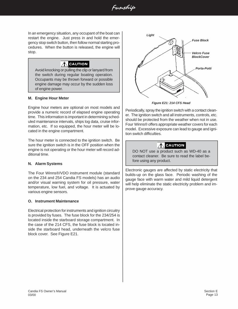
Section EPage 13
Candia FS Owner’s Manual03/00
Periodically, spray the ignition switch with a contact clean-er. The ignition switch and all instruments, controls, etc.should be protected from the weather when not in use.Four Winns® offers appropriate weather covers for eachmodel. Excessive exposure can lead to gauge and igni-tion switch difficulties.
DO NOT use a product such as WD-40 as acontact cleaner. Be sure to read the label be-fore using any product.
Electronic gauges are affected by static electricity thatbuilds-up on the glass face. Periodic washing of thegauge face with warm water and mild liquid detergentwill help eliminate the static electricity problem and im-prove gauge accuracy.
In an emergency situation, any occupant of the boat canrestart the engine. Just press in and hold the emer-gency stop switch button, then follow normal starting pro-cedures. When the button is released, the engine willstop.
Avoid knocking or pulling the clip or lanyard fromthe switch during regular boating operation.Occupants may be thrown forward or possibleengine damage may occur by the sudden lossof engine power.
M. Engine Hour Meter
Engine hour meters are optional on most models andprovide a numeric record of elapsed engine operatingtime. This information is important in determining sched-uled maintenance intervals, ships log data, cruise infor-mation, etc. If so equipped, the hour meter will be lo-cated in the engine compartment.
The hour meter is connected to the ignition switch. Besure the ignition switch is in the OFF position when theengine is not operating or the hour meter will record ad-ditional time.
N. Alarm Systems
The Four Winns®/VDO instrument module (standardon the 234 and 254 Candia FS models) has an audioand/or visual warning system for oil pressure, watertemperature, low fuel, and voltage. It is actuated byvarious engine sensors.
O. Instrument Maintenance
Electrical protection for instruments and ignition circuitryis provided by fuses. The fuse block for the 234/254 islocated inside the starboard storage compartment. Inthe case of the 214 CFS, the fuse block is located in-side the starboard head, underneath the velcro fuseblock cover. See Figure E21.
Light
Fuse Block
Porta-Potti
Velcro FuseBlockCover
Figure E21: 214 CFS Head
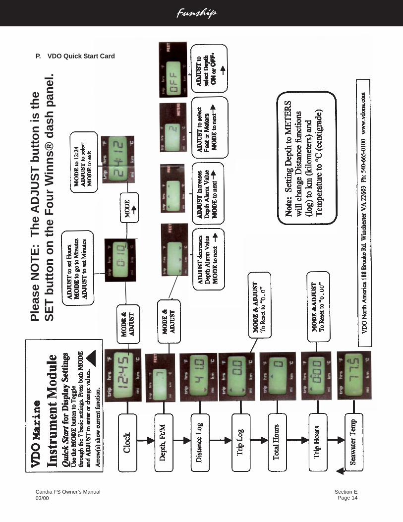
Page 14Candia FS Owner’s Manual03/00
Section E
Ple
ase
NO
TE
: T
he
AD
JUS
T b
utt
on
is t
he
SE
T b
utt
on
on
th
e F
ou
r W
inn
s® d
ash
pan
el.
P. VDO Quick Start Card
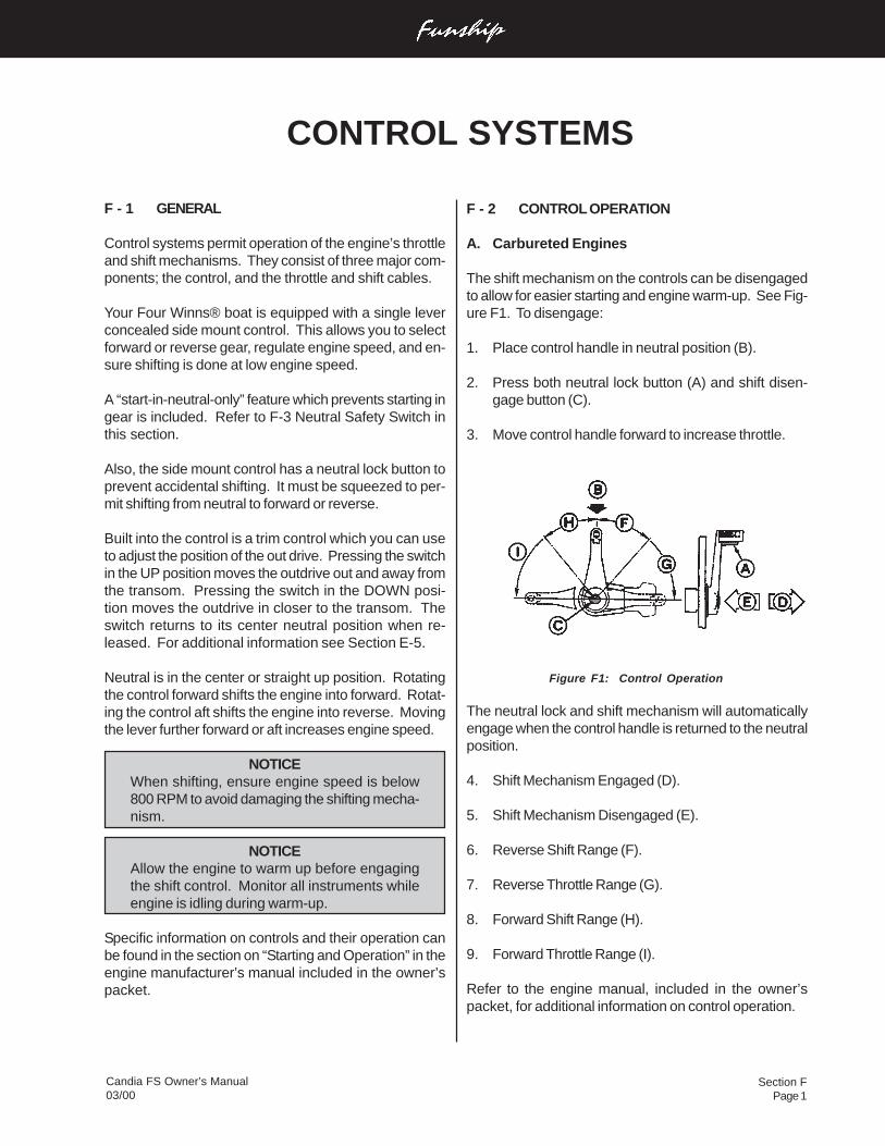
Candia FS Owner’s Manual03/00
Section FPage 1
CONTROL SYSTEMS
F - 2 CONTROL OPERATION
A. Carbureted Engines
The shift mechanism on the controls can be disengagedto allow for easier starting and engine warm-up. See Fig-ure F1. To disengage:
1. Place control handle in neutral position (B).
2. Press both neutral lock button (A) and shift disen-gage button (C).
3. Move control handle forward to increase throttle.
Figure F1: Control Operation
The neutral lock and shift mechanism will automaticallyengage when the control handle is returned to the neutralposition.
4. Shift Mechanism Engaged (D).
5. Shift Mechanism Disengaged (E).
6. Reverse Shift Range (F).
7. Reverse Throttle Range (G).
8. Forward Shift Range (H).
9. Forward Throttle Range (I).
Refer to the engine manual, included in the owner’spacket, for additional information on control operation.
F - 1 GENERAL
Control systems permit operation of the engine’s throttleand shift mechanisms. They consist of three major com-ponents; the control, and the throttle and shift cables.
Your Four Winns® boat is equipped with a single leverconcealed side mount control. This allows you to selectforward or reverse gear, regulate engine speed, and en-sure shifting is done at low engine speed.
A “start-in-neutral-only” feature which prevents starting ingear is included. Refer to F-3 Neutral Safety Switch inthis section.
Also, the side mount control has a neutral lock button toprevent accidental shifting. It must be squeezed to per-mit shifting from neutral to forward or reverse.
Built into the control is a trim control which you can useto adjust the position of the out drive. Pressing the switchin the UP position moves the outdrive out and away fromthe transom. Pressing the switch in the DOWN posi-tion moves the outdrive in closer to the transom. Theswitch returns to its center neutral position when re-leased. For additional information see Section E-5.
Neutral is in the center or straight up position. Rotatingthe control forward shifts the engine into forward. Rotat-ing the control aft shifts the engine into reverse. Movingthe lever further forward or aft increases engine speed.
NOTICEWhen shifting, ensure engine speed is below800 RPM to avoid damaging the shifting mecha-nism.
NOTICEAllow the engine to warm up before engagingthe shift control. Monitor all instruments whileengine is idling during warm-up.
Specific information on controls and their operation canbe found in the section on “Starting and Operation” in theengine manufacturer’s manual included in the owner’spacket.
Candia FS Owner’s Manual03/00
Section FPage 2
DO NOT attempt control adjustments unless youare familiar with control systems service proce-dures. Control misadjustment can cause lossof control.
Other lubrication, adjustment and maintenance instruc-tions are provided by the control manufacturer and areincluded in the owner’s information packet.
B. Fuel Injected Engines (EFI)
On fuel injected engines, starting the engine is mucheasier and faster. It is not necessary to use the throttlewhile in neutral to cold-start the engine. Simply turn thekey and allow the engine to warm up.
For additional information, refer to the section on “Start-ing and Operation” in the engine manufacturer’s manualincluded in the owner’s information packet.
F - 3 NEUTRAL SAFETY SWITCH
Control systems usually incorporate neutral safety switch-es within their design. This device prevents the enginefrom being started while the shift lever is in any positionother than the neutral position. If the engine will not start,slight movement of the shift lever may be necessary tolocate the neutral position and disengage the safety cut-out switch. Control or cable adjustments are required tocorrect this condition should it persist. See yourFour Winns® dealer for necessary control and cable ad-justments.
F - 4 CONTROL SYSTEM MAINTENANCE
Periodic inspections of the control, cables, and all con-nections should be made. Signs of looseness, rust, cor-rosion, wear, cable jacket cracks or other deteriorationrequire immediate system servicing. Replace all dam-aged components.
Generally, periodic lubrication of all moving parts and con-nections with a light, waterproof grease is in order. Cablescan be lubricated by positioning them to their fullest ex-tension and applying light grease to the inner cable nearthe jacket. Working the cables back and forth will distrib-ute the grease in the inner cable. Reapply the grease ifnecessary.
Lubrication should be performed as often as necessaryto keep the system operating smoothly. Cable manufac-turers such as Teleflex® and Morse® often offer specialtools to make cable lubrication easier.
Cable and control adjustments may become necessary.Adjustment screws in the control, on the cables and inthe linkage are provided.
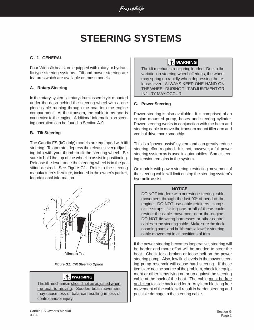
Section GPage 1
Candia FS Owner’s Manual03/00
G - 1 GENERAL
Four Winns® boats are equipped with rotary or hydrau-lic type steering systems. Tilt and power steering arefeatures which are available on most models.
A. Rotary Steering
In the rotary system, a rotary drum assembly is mountedunder the dash behind the steering wheel with a onepiece cable running through the boat into the enginecompartment. At the transom, the cable turns and isconnected to the engine. Additional information on steer-ing operation can be found in Section A-9.
B. Tilt Steering
The Candia FS (I/O only) models are equipped with tiltsteering. To operate, depress the release lever (adjust-ing tab) with your thumb to tilt the steering wheel. Besure to hold the top of the wheel to assist in positioning.Release the lever once the steering wheel is in the po-sition desired. See Figure G1. Refer to the steeringmanufacturer’s literature, included in the owner’s packet,for additional information.
Figure G1: Tilt Steering Option
The tilt mechanism should not be adjusted whenthe boat is moving. Sudden boat movementmay cause loss of balance resulting in loss ofcontrol and/or injury.
STEERING SYSTEMS
The tilt mechanism is spring loaded. Due to thevariation in steering wheel offerings, the wheelmay spring up rapidly when depressing the re-lease lever. ALWAYS KEEP ONE HAND ONTHE WHEEL DURING TILT ADJUSTMENT ORINJURY MAY OCCUR.
C. Power Steering
Power steering is also available. It is comprised of anengine mounted pump, hoses and steering cylinder.Power steering works in conjunction with the helm andsteering cable to move the transom mount tiller arm andvertical drive more smoothly.
This is a “power assist” system and can greatly reducesteering effort required. It is not, however, a full powersteering system as is used in automobiles. Some steer-ing tension remains in the system.
On models with power steering, restricting movement ofthe steering cable will limit or stop the steering system’shydraulic assist.
NOTICEDO NOT interfere with or restrict steering cablemovement through the last 90o of bend at theengine. DO NOT use cable retainers, clampsor tie straps. Using one or all of these couldrestrict the cable movement near the engine.DO NOT tie wiring harnesses or other controlcables to the steering cable. Make sure the deckcoaming pads and bulkheads allow for steeringcable movement in all positions of trim.
If the power steering becomes inoperative, steering willbe harder and more effort will be needed to steer theboat. Check for a broken or loose belt on the powersteering pump. Also, low fluid levels in the power steer-ing pump reservoir will cause hard steering. If theseitems are not the source of the problem, check for equip-ment or other items lying on or up against the steeringcable at the back of the boat. The cable must be freeand clear to slide back and forth. Any item blocking freemovement of the cable will result in harder steering andpossible damage to the steering cable.
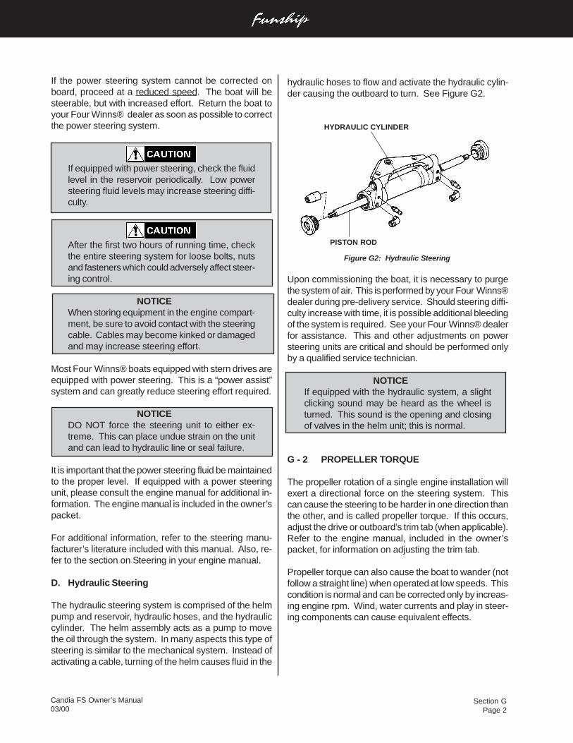
Section GPage 2
Candia FS Owner’s Manual03/00
hydraulic hoses to flow and activate the hydraulic cylin-der causing the outboard to turn. See Figure G2.
Figure G2: Hydraulic Steering
Upon commissioning the boat, it is necessary to purgethe system of air. This is performed by your Four Winns®dealer during pre-delivery service. Should steering diffi-culty increase with time, it is possible additional bleedingof the system is required. See your Four Winns® dealerfor assistance. This and other adjustments on powersteering units are critical and should be performed onlyby a qualified service technician.
NOTICEIf equipped with the hydraulic system, a slightclicking sound may be heard as the wheel isturned. This sound is the opening and closingof valves in the helm unit; this is normal.
G - 2 PROPELLER TORQUE
The propeller rotation of a single engine installation willexert a directional force on the steering system. Thiscan cause the steering to be harder in one direction thanthe other, and is called propeller torque. If this occurs,adjust the drive or outboard’s trim tab (when applicable).Refer to the engine manual, included in the owner’spacket, for information on adjusting the trim tab.
Propeller torque can also cause the boat to wander (notfollow a straight line) when operated at low speeds. Thiscondition is normal and can be corrected only by increas-ing engine rpm. Wind, water currents and play in steer-ing components can cause equivalent effects.
If the power steering system cannot be corrected onboard, proceed at a reduced speed. The boat will besteerable, but with increased effort. Return the boat toyour Four Winns® dealer as soon as possible to correctthe power steering system.
If equipped with power steering, check the fluidlevel in the reservoir periodically. Low powersteering fluid levels may increase steering diffi-culty.
After the first two hours of running time, checkthe entire steering system for loose bolts, nutsand fasteners which could adversely affect steer-ing control.
NOTICEWhen storing equipment in the engine compart-ment, be sure to avoid contact with the steeringcable. Cables may become kinked or damagedand may increase steering effort.
Most Four Winns® boats equipped with stern drives areequipped with power steering. This is a “power assist”system and can greatly reduce steering effort required.
NOTICEDO NOT force the steering unit to either ex-treme. This can place undue strain on the unitand can lead to hydraulic line or seal failure.
It is important that the power steering fluid be maintainedto the proper level. If equipped with a power steeringunit, please consult the engine manual for additional in-formation. The engine manual is included in the owner’spacket.
For additional information, refer to the steering manu-facturer’s literature included with this manual. Also, re-fer to the section on Steering in your engine manual.
D. Hydraulic Steering
The hydraulic steering system is comprised of the helmpump and reservoir, hydraulic hoses, and the hydrauliccylinder. The helm assembly acts as a pump to movethe oil through the system. In many aspects this type ofsteering is similar to the mechanical system. Instead ofactivating a cable, turning of the helm causes fluid in the
HYDRAULIC CYLINDER
PISTON ROD
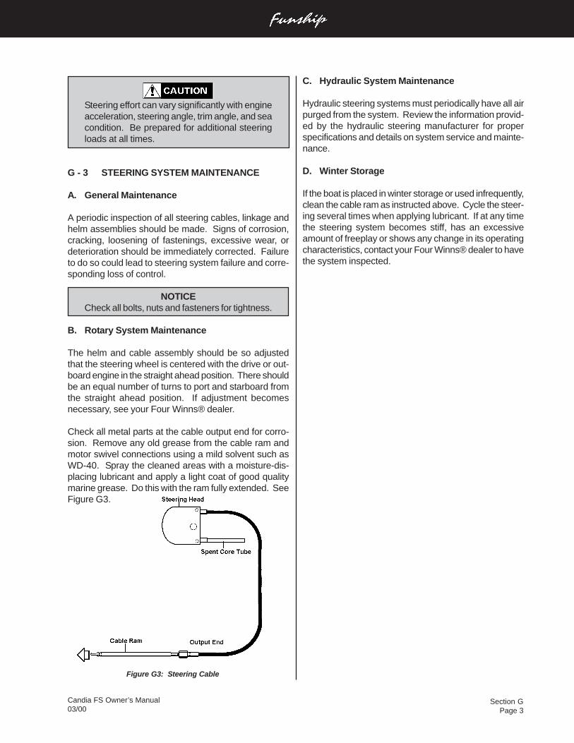
Section GPage 3
Candia FS Owner’s Manual03/00
C. Hydraulic System Maintenance
Hydraulic steering systems must periodically have all airpurged from the system. Review the information provid-ed by the hydraulic steering manufacturer for properspecifications and details on system service and mainte-nance.
D. Winter Storage
If the boat is placed in winter storage or used infrequently,clean the cable ram as instructed above. Cycle the steer-ing several times when applying lubricant. If at any timethe steering system becomes stiff, has an excessiveamount of freeplay or shows any change in its operatingcharacteristics, contact your Four Winns® dealer to havethe system inspected.
Figure G3: Steering Cable
Steering effort can vary significantly with engineacceleration, steering angle, trim angle, and seacondition. Be prepared for additional steeringloads at all times.
G - 3 STEERING SYSTEM MAINTENANCE
A. General Maintenance
A periodic inspection of all steering cables, linkage andhelm assemblies should be made. Signs of corrosion,cracking, loosening of fastenings, excessive wear, ordeterioration should be immediately corrected. Failureto do so could lead to steering system failure and corre-sponding loss of control.
NOTICECheck all bolts, nuts and fasteners for tightness.
B. Rotary System Maintenance
The helm and cable assembly should be so adjustedthat the steering wheel is centered with the drive or out-board engine in the straight ahead position. There shouldbe an equal number of turns to port and starboard fromthe straight ahead position. If adjustment becomesnecessary, see your Four Winns® dealer.
Check all metal parts at the cable output end for corro-sion. Remove any old grease from the cable ram andmotor swivel connections using a mild solvent such asWD-40. Spray the cleaned areas with a moisture-dis-placing lubricant and apply a light coat of good qualitymarine grease. Do this with the ram fully extended. SeeFigure G3.
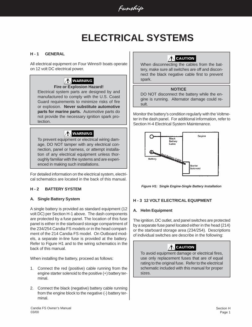
Section HPage 1
Candia FS Owner’s Manual03/00
ELECTRICAL SYSTEMS
Red Battery Cable
H - 1 GENERAL
All electrical equipment on Four Winns® boats operateon 12 volt DC electrical power.
Fire or Explosion Hazard!Electrical system parts are designed by andmanufactured to comply with the U.S. CoastGuard requirements to minimize risks of fireor explosion. Never substitute automotiveparts for marine parts. Automotive parts donot provide the necessary ignition spark pro-tection.
To prevent equipment or electrical wiring dam-age, DO NOT tamper with any electrical con-nection, panel or harness, or attempt installa-tion of any electrical equipment unless thor-oughly familiar with the systems and are experi-enced in making such installations.
For detailed information on the electrical system, electri-cal schematics are located in the back of this manual.
H - 2 BATTERY SYSTEM
A. Single Battery System
A single battery is provided as standard equipment (12volt DC) per Section H-1 above. The dash componentsare protected by a fuse panel. The location of this fusepanel is either in the starboard storage compartment ofthe 234/254 Candia FS models or in the head compart-ment of the 214 Candia FS model. On Outboard mod-els, a separate in-line fuse is provided at the battery.Refer to Figure H1 and to the wiring schematics in theback of this manual.
When installing the battery, proceed as follows:
1. Connect the red (positive) cable running from theengine starter solenoid to the positive (+) battery ter-minal.
2. Connect the black (negative) battery cable runningfrom the engine block to the negative (-) battery ter-minal.
When disconnecting the cables from the bat-tery, make sure all switches are off and discon-nect the black negative cable first to preventspark.
NOTICEDO NOT disconnect the battery while the en-gine is running. Alternator damage could re-sult.
Monitor the battery’s condition regularly with the Voltme-ter in the dash panel. For additional information, refer toSection H-4 Electrical System Maintenance.
Figure H1: Single Engine-Single Battery Installation
H - 3 12 VOLT ELECTRICAL EQUIPMENT
A. Helm Equipment
The ignition, DC outlet, and panel switches are protectedby a separate fuse panel located either in the head (214)or the starboard storage area (234/254). Descriptionsof individual switches are describe in the following:
To avoid equipment damage or electrical fires,use only replacement fuses that are of equalrating to the original fuse. Refer to the electricalschematic included with this manual for propersizes.
Section HPage 2
Candia FS Owner’s Manual03/00
Horn - To sound the horn, push the HORN button.
Aft Bilge Pump - The PUMP switch at the dash is usedto manually activate the bilge pump in the enginecompartment. The bilge pump is used to remove waterfrom the bilge (bottom of the hull) area of the boat bypumping that water overboard.
On all Candia FS models, the aft bilge pump is equippedwith an automatic bilge switch and will operate when-ever bilge water rises above the pump stop level. Thiswill cause the internal float to move upward and activatethe pump.
When leaving your boat unattended for an extended pe-riod, check the charge on the battery(s) periodically. Alsocheck the water level in the bilge and make sure thefloat switch is functional.
If the automatic bilge pump must be disabled, discon-nect the wiring plug near the bilge pump.
Bilge Blower- The BLOWER switch is used to activatethe bilge blower. The bilge blower is used to removeany gas vapors that may have accumulated in the bilgeor engine areas.
Gasoline vapors can explode resulting in injury ordeath.
1. Before starting the engine, check the enginecompartment bilge for gasoline or vapors.
2. Operate blower for four (4) minutes, and verifyblower operation. Run blower when vessel isoperating below cruising speed.
To verify blower is operating place your handover the vents. DO NOT rely on the sound ofthe blower. Be sure a substantial amount of airis being exhausted by the bilge blower. Checkthe bilge blower system often, preferably be-fore each cruise.
Navigation & Anchor Lights - Moving the NAV/ANC LTSswitch towards the NAV position activates the bow lightsand the all-around light or both portions of the mast light.Move the switch to the ANC position to activate the all-around light or both the fore and aft portion of the mastlight. The center switch position is OFF.
Wipers - The WIPER switch activates the windshieldwiper. This is an option for the starboard side only.
Accessories - Additional 12 volt equipment may be addedto the boat using the accessory switch. Certain acces-sories may be wired directly to the fuse block below thedash. For more information, refer to Section H-3B Instal-lation of Additional 12 Volt Equipment.
Cockpit Lights - The CKPT LTS switch is used to acti-vate the cockpit (courtesy) lights.
B. Installation of Additional 12 Volt Equipment
On the fuse panel, non-factory installed 12 volt acces-sory equipment can be connected to the “ACC” termi-nal. Accessory equipment can also be wired directly tothe “ACC” switch on the dash.
Be sure to provide proper fuse protection for all12 volt equipment that is installed. Accessorycurrent should be limited to 20 amp if the con-nection is made to the fuse block. If the “ACC”switch is used, the current should be limited to15 amp. Gauge and 12 volt equipment mayoperate improperly and cause possible internaldamage at higher levels.
C. Interior Equipment
Stereo - On all models, the stereo is mounted at thedash. It is connected at the fuse block and has a sepa-rate in-line fuse provided in the stereo wiring for pro-tection. For stereo operation, please refer to themanufacturer’s manual included in the owner’s infor-mation packet.
NOTICEPlease note that when the ignition switch isplaced in the off position the stereo is also shutoff. This applies to 2000 models and neweronly. On prior 2000 model boats, follow thedirections indicated in your stereo manu-facturer’s operating instructions.
H - 4 ELECTRICAL SYSTEM MAINTENANCE
A. Battery Maintenance
Be sure to keep the batteries charged. Also, keep thebatteries clean, especially the terminals and connection
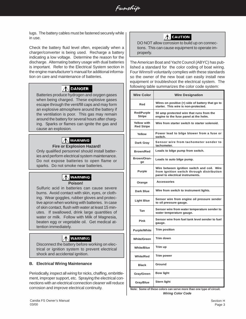
Section HPage 3
Candia FS Owner’s Manual03/00
DO NOT allow corrosion to build up on connec-tions. This can cause equipment to operate im-properly.
The American Boat and Yacht Council (ABYC) has pub-lished a standard for the color coding of boat wiring.Four Winns® voluntarily complies with these standardsso the owner of the new boat can easily install newequipment or troubleshoot the electrical system. Thefollowing table summarizes the color code system:
Note: Some of these colors can serve more than one type of circuit.
Wiring Color Code
roloCeriW noitangiseDeriW
deR otogtahtyrettabfoedis)+(evitisopnoseriW.detcetorp-nonsieriwsihT.retrats
elpruP/deRepirtS
ehtmorfsnurtahteriwdetcetorppma05.mlehehttalenapesufehtotenigne
htiwwolleYepirtSdeR
.dionelosretratsothctiwsretratsmorferiW
wolleY roesufamorfrewolbeglibotdaelrewoP.hctiws
yarGkraD otrednesretemohcatmorferiwrosneS.retemohcat
deR/nworB .hctiwsmorfpmupeglibotsdaeL
-narO/nworBeg
.pmupeglibotuaotsdaeL
elpruPeriW.liocdnahctiwsnoitingineewteberiWnoitubirtsidhguorhthctiwsnoitingimorf
.stnemurtsnilacirtceleotlenap
egnarO seirosseccA
eulBkraD .sthgiltnemurtsniothctiwsmorferiW
eulBthgiL redneserusserplioenignemorferiwrosneS.eguagerusserplioot
naT otredneserutarepmetretawmorferiwrosneS.eguagerutarepmetretaw
kniP leufotredneslevelknatleufmorferiwrosneS.eguag
etihW/elpruP noitisopmirT
neerG/etihW nwodmirT
eulB/etihW pumirT
deR/etihW rewopmirT
kcalB dnuorG
neerG/yarG thgilwoB
eulB/yarG thgilnretS
lugs. The battery cables must be fastened securely whilein use.
Check the battery fluid level often, especially when acharger/converter is being used. Recharge a batteryindicating a low voltage. Determine the reason for thedischarge. Alternating battery usage with dual batteriesis important. Refer to the Electrical System section inthe engine manufacturer’s manual for additional informa-tion on care and maintenance of batteries.
Batteries produce hydrogen and oxygen gaseswhen being charged. These explosive gasesescape through the vent/fill caps and may forman explosive atmosphere around the battery ifthe ventilation is poor. This gas may remainaround the battery for several hours after charg-ing. Sparks or flames can ignite the gas andcause an explosion.
Fire or Explosion Hazard!Only qualified personnel should install batter-ies and perform electrical system maintenance.Do not expose batteries to open flame orsparks. Do not smoke near batteries.
Poison!Sulfuric acid in batteries can cause severeburns. Avoid contact with skin, eyes, or cloth-ing. Wear goggles, rubber gloves and protec-tive apron when working with batteries. In caseof skin contact, flush with water at least 15 min-utes. If swallowed, drink large quantities ofwater or milk. Follow with Milk of Magnesia,beaten egg or vegetable oil. Get medical at-tention immediately.
Disconnect the battery before working on elec-trical or ignition system to prevent electricalshock and accidental ignition.
B. Electrical Wiring Maintenance
Periodically, inspect all wiring for nicks, chaffing, embrittle-ment, improper support, etc. Spraying the electrical con-nections with an electrical connection cleaner will reducecorrosion and improve electrical continuity.
Section HPage 4
Candia FS Owner’s Manual03/00
increased and the attack on the less active metal is de-creased, as compared to when these metals are nottouching.
C. Corrosion Prevention
Anti-corrosion anodes are attached to the bottom of thegimbal housing to prevent corrosion to your stern driveand underwater parts. These anodes will be slowlyeroded away by galvanic action and require periodic in-spection. Please refer to the section on “Anti-CorrosionAnodes” in your engine manufacturer’s manual for ad-ditional information. The engine manual is included inthe owner’s packet.
H - 5 STRAY CURRENT CORROSION
A. General
Electrically induced underwater corrosion occasionallyaffects boats and their related components. This is re-ferred to as “Stray Current Corrosion” and appears assurface pitting or deterioration. Stray current corrosionis the decomposition of chemical compounds by electriccurrent.
Stray current corrosion can be caused by the polarity ofthe dockside wiring system of the boat being reversedfrom the power source (reversed polarity) or surround-ing boats, an improperly wired battery installation, otherboats that are in close proximity that have electrical powerleakages, or any other source close to the boat that haselectrical power leakage into the water. Stern drive unitsare especially vulnerable to stray current corrosion.
Periodically inspect the drive components and thru-hullfittings to determine if stray current corrosion damageexists. If corrosion damage is found, determine and cor-rect the cause of stray current to prevent further dam-age. Consult an experienced marine electrician or con-tact your Four Winns® dealer for assistance.
The use of some shore power battery chargers, whilethe boat is in the water and the battery is connected tothe system, can cause stray current corrosion. Have anexperienced marine electrician review any batterycharger installation to ensure a stray current corrosionproblem will not develop. An improper battery connec-tion is a common cause of stray current corrosion.
NOTICEUse only “Coast Guard” approved battery charg-ers. Consult your Four Winns® dealer for hisrecommendations.
Corrosion is usually more prevalent in polluted or saltwater than in clean water. It is also more likely to occurwhen dockage is in an area with steel piers, large metalboats, or where shore power is in use.
B. Galvanic Corrosion
Galvanic corrosion results from a potential electrical dif-ference existing between dissimilar metals immersed ina conductive solution (e.g., salt water). If these metalstouch or are otherwise electrically connected, this po-tential difference produces an electron flow betweenthem. The attack on the more active metal is usually
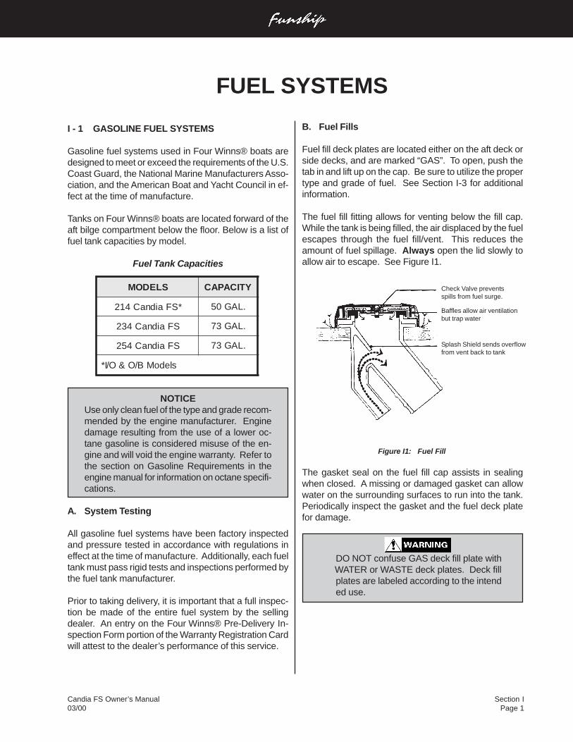
Section IPage 1
Candia FS Owner’s Manual03/00
I - 1 GASOLINE FUEL SYSTEMS
Gasoline fuel systems used in Four Winns® boats aredesigned to meet or exceed the requirements of the U.S.Coast Guard, the National Marine Manufacturers Asso-ciation, and the American Boat and Yacht Council in ef-fect at the time of manufacture.
Tanks on Four Winns® boats are located forward of theaft bilge compartment below the floor. Below is a list offuel tank capacities by model.
Fuel Tank Capacities
NOTICEUse only clean fuel of the type and grade recom-mended by the engine manufacturer. Enginedamage resulting from the use of a lower oc-tane gasoline is considered misuse of the en-gine and will void the engine warranty. Refer tothe section on Gasoline Requirements in theengine manual for information on octane specifi-cations.
A. System Testing
All gasoline fuel systems have been factory inspectedand pressure tested in accordance with regulations ineffect at the time of manufacture. Additionally, each fueltank must pass rigid tests and inspections performed bythe fuel tank manufacturer.
Prior to taking delivery, it is important that a full inspec-tion be made of the entire fuel system by the sellingdealer. An entry on the Four Winns® Pre-Delivery In-spection Form portion of the Warranty Registration Cardwill attest to the dealer’s performance of this service.
B. Fuel Fills
Fuel fill deck plates are located either on the aft deck orside decks, and are marked “GAS”. To open, push thetab in and lift up on the cap. Be sure to utilize the propertype and grade of fuel. See Section I-3 for additionalinformation.
The fuel fill fitting allows for venting below the fill cap.While the tank is being filled, the air displaced by the fuelescapes through the fuel fill/vent. This reduces theamount of fuel spillage. Always open the lid slowly toallow air to escape. See Figure I1.
Figure I1: Fuel Fill
The gasket seal on the fuel fill cap assists in sealingwhen closed. A missing or damaged gasket can allowwater on the surrounding surfaces to run into the tank.Periodically inspect the gasket and the fuel deck platefor damage.
DO NOT confuse GAS deck fill plate with WATER or WASTE deck plates. Deck fill
plates are labeled according to the intended use.
FUEL SYSTEMS
Check Valve preventsspills from fuel surge.
Baffles allow air ventilationbut trap water
Splash Shield sends overflowfrom vent back to tank
SLEDOM YTICAPAC
*SFaidnaC412 .LAG05
SFaidnaC432 .LAG37
SFaidnaC452 .LAG37
sledoMB/O&O/I*
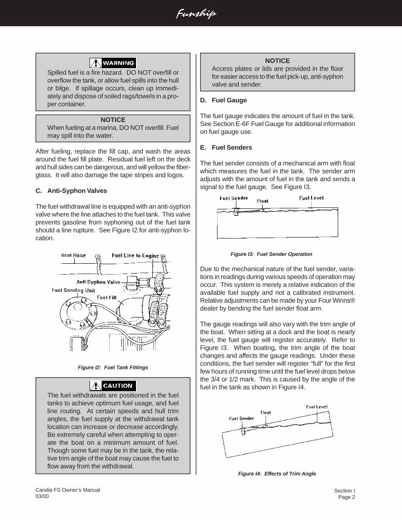
Section IPage 2
Candia FS Owner’s Manual03/00
NOTICEAccess plates or lids are provided in the floorfor easier access to the fuel pick-up, anti-syphonvalve and sender.
D. Fuel Gauge
The fuel gauge indicates the amount of fuel in the tank.See Section E-6F Fuel Gauge for additional informationon fuel gauge use.
E. Fuel Senders
The fuel sender consists of a mechanical arm with floatwhich measures the fuel in the tank. The sender armadjusts with the amount of fuel in the tank and sends asignal to the fuel gauge. See Figure I3.
Figure I3: Fuel Sender Operation
Due to the mechanical nature of the fuel sender, varia-tions in readings during various speeds of operation mayoccur. This system is merely a relative indication of theavailable fuel supply and not a calibrated instrument.Relative adjustments can be made by your Four Winns®dealer by bending the fuel sender float arm.
The gauge readings will also vary with the trim angle ofthe boat. When sitting at a dock and the boat is nearlylevel, the fuel gauge will register accurately. Refer toFigure I3. When boating, the trim angle of the boatchanges and affects the gauge readings. Under theseconditions, the fuel sender will register “full” for the firstfew hours of running time until the fuel level drops belowthe 3/4 or 1/2 mark. This is caused by the angle of thefuel in the tank as shown in Figure I4.
Figure I4: Effects of Trim Angle
Spilled fuel is a fire hazard. DO NOT overfill oroverflow the tank, or allow fuel spills into the hullor bilge. If spillage occurs, clean up immedi-ately and dispose of soiled rags/towels in a pro-per container.
NOTICEWhen fueling at a marina, DO NOT overfill. Fuelmay spill into the water.
After fueling, replace the fill cap, and wash the areasaround the fuel fill plate. Residual fuel left on the deckand hull sides can be dangerous, and will yellow the fiber-glass. It will also damage the tape stripes and logos.
C. Anti-Syphon Valves
The fuel withdrawal line is equipped with an anti-syphonvalve where the line attaches to the fuel tank. This valveprevents gasoline from syphoning out of the fuel tankshould a line rupture. See Figure I2 for anti-syphon lo-cation.
Figure I2: Fuel Tank Fittings
The fuel withdrawals are positioned in the fueltanks to achieve optimum fuel usage, and fuelline routing. At certain speeds and hull trimangles, the fuel supply at the withdrawal tanklocation can increase or decrease accordingly.Be extremely careful when attempting to oper-ate the boat on a minimum amount of fuel.Though some fuel may be in the tank, the rela-tive trim angle of the boat may cause the fuel toflow away from the withdrawal.
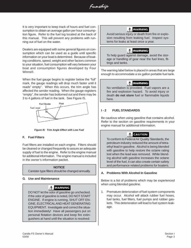
Section IPage 3
Candia FS Owner’s Manual03/00
Avoid serious injury or death from fire or explo-sion resulting from leaking fuel. Inspect sys-tems for leaks at least once a year.
To help guard against damage, avoid the stor-age or handling of gear near the fuel lines, fit-tings and tanks.
The warning label below is placed in areas that are largeenough to accommodate a six gallon portable fuel tank.
No ventilation is provided. Fuel vapors are afire and explosion hazard. To avoid injury ordeath do not store fuel or flammable liquidshere.
I - 2 FUEL STANDARDS
Be cautious when using gasoline that contains alcohol.Refer to the section on gasoline requirements in yourengine manual for additional information.
To conform to Federal Air Quality Standards, thepetroleum industry reduced the amount of tetra-ethyl lead in gasoline. Alcohol is being blendedwith gasoline to help restore the octane ratinglost when the lead was removed. While blend-ing alcohol with gasoline increases the octanelevel of the fuel, it can also create certain safetyand performance related problems for boaters.
A. Problems With Alcohol In Gasoline
Below is a list of problems which may be experiencedwhen using blended gasoline.
1. Premature deterioration of fuel system componentsmay occur. Alcohol will attack rubber fuel hoses,fuel tanks, fuel filters, fuel pumps and rubber gas-kets. This deterioration will lead to fuel system leak-age.
It is very important to keep track of hours and fuel con-sumption to obtain an average gallon per hour consump-tion figure. Refer to the fuel log located at the back ofthis manual. This will prevent any problems with run-ning out of fuel on the water.
Dealers are equipped with some general figures on con-sumption which can be used as a guide until specificinformation on your boat is determined. Because of boat-ing conditions, speed, weight and other factors commonto your situation, fuel consumption will vary between yourboat and consumption figures developed by FourWinns®.
When the fuel gauge begins to register below the “full”mark, the gauge readings will drop much faster until itreads” empty”. When this occurs, the trim angle hasaffected the sender reading. When the gauge registers“empty”, the sender has bottomed out and there may be3 to 4 gallons of fuel in the tank. See Figure I5.
Figure I5: Trim Angle Effect with Low Fuel
F. Fuel Filters
Fuel filters are installed on each engine. Filters shouldbe cleaned or changed frequently to assure an adequatesupply of fuel to the engine. Refer to the engine manualfor additional information. The engine manual is includedin the owner’s information packet.
NOTICECanister-type filters should be changed annually.
G. Use and Maintenance
DO NOT let the odor of gasoline go unchecked.If the odor of gasoline is noted, DO NOT STARTENGINE. If engine is running, SHUT OFF EN-GINE, ELECTRICAL AND HEAT GENERATINGEQUIPMENT. Investigate and correct the situa-tion immediately! Have all passengers put onpersonal flotation devices and keep fire extin-guishers at hand until the situation is resolved.
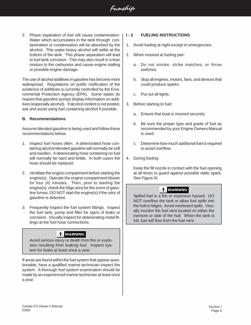
Section IPage 4
Candia FS Owner’s Manual03/00
I - 3 FUELING INSTRUCTIONS
1. Avoid fueling at night except in emergencies.
2. When moored at fueling pier:
a. Do not smoke, strike matches, or throwswitches.
b. Stop all engines, motors, fans, and devices thatcould produce sparks.
c. Put out all lights.
3. Before starting to fuel:
a. Ensure that boat is moored securely.
b. Be sure the proper type and grade of fuel asrecommended by your Engine Owners Manualis used.
c. Determine how much additional fuel is requiredto avoid overflow.
4. During fueling:
Keep the fill nozzle in contact with the fuel openingat all times to guard against possible static spark.See Figure I6.
Spilled fuel is a fire or explosion hazard. DONOT overflow the tank or allow fuel spills intothe hull or bilges. Avoid overboard spills. Visu-ally monitor the fuel vent located on either thetransom or side of the hull. When the tank isfull, fuel will flow from the fuel vent.
2. Phase separation of fuel will cause contamination.Water which accumulates in the tank through con-tamination or condensation will be absorbed by thealcohol. This water-heavy alcohol will settle at thebottom of the tank. This phase separation will leadto fuel tank corrosion. This may also result in a leanmixture to the carburetor and cause engine stallingor possible engine damage.
The use of alcohol additives in gasoline has become morewidespread. Regulations on public notification of theexistence of additives is currently controlled by the Envi-ronmental Protection Agency (EPA). Some states dorequire that gasoline pumps display information on addi-tives (especially alcohol). If alcohol content is not posted,ask and avoid using fuel containing alcohol if possible.
B. Recommendations
Assume blended gasoline is being used and follow theserecommendations below.
1. Inspect fuel hoses often. A deteriorated hose con-taining alcohol blended gasoline will normally be softand swollen. A deteriorating hose containing no fuelwill normally be hard and brittle. In both cases thehose should be replaced.
2. Ventilate the engine compartment before starting theengine(s). Operate the engine compartment blowerfor four (4) minutes. Then, prior to starting theengine(s), check the bilge area for the scent of gaso-line fumes; DO NOT start the engine(s) if the odor ofgasoline is detected.
3. Frequently inspect the fuel system fittings. Inspectthe fuel tank, pump and filter for signs of leaks orcorrosion. Visually inspect for deteriorating metal fit-tings at the fuel hose connections.
Avoid serious injury or death from fire or explo-sion resulting from leaking fuel. Inspect sys-tem for leaks at least once a year.
If areas are found within the fuel system that appear ques-tionable, have a qualified marine technician inspect thesystem. A thorough fuel system examination should bemade by an experienced marine technician at least oncea year.
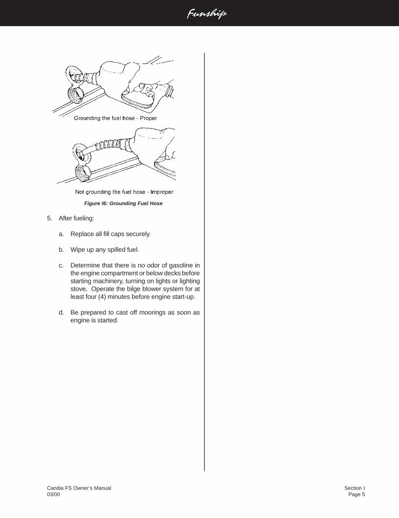
Section IPage 5
Candia FS Owner’s Manual03/00
Figure I6: Grounding Fuel Hose
5. After fueling:
a. Replace all fill caps securely.
b. Wipe up any spilled fuel.
c. Determine that there is no odor of gasoline inthe engine compartment or below decks beforestarting machinery, turning on lights or lightingstove. Operate the bilge blower system for atleast four (4) minutes before engine start-up.
d. Be prepared to cast off moorings as soon asengine is started.
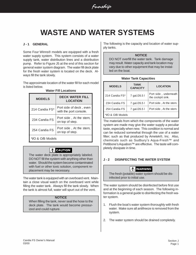
Section JPage 1
Candia FS Owner’s Manual03/00
WASTE AND WATER SYSTEMS
SLEDOMLLIFRETAWKCED
NOITACOL
*SFaidnaC412neve,kcedfoedistroP
.elosnoctropehthtiw
SFaidnaC432,nretsehttA,edistroP
.petsfopotno
SFaidnaC452,nretsehttA,edistroP
.petsfopotno
sledoMB/O&O/I*
SLEDOMKNAT
YTICAPACNOITACOL
*SFaidnaC412 l5.62/.lag7htaenrednu,edistroP
.knistipkcoceht
SFaidnaC432 l5.62/.lag7 .nretsehttA,edistroP
SFaidnaC452 l5.62/.lag7 .nretsehttA,edistroP
sledoMB/O&O/I*
J - 1 GENERAL
Some Four Winns® models are equipped with a freshwater supply system. This system consists of a watersupply tank, water distribution lines and a distributionpump. Refer to Figure J5 at the end of this section forgeneral water system diagram. The water fill deck platefor the fresh water system is located on the deck. Al-ways fill the tank slowly.
The approximate location of the water fill for each modelis listed below.
Water Fill Locations
The water deck plate is appropriately labeled.DO NOT fill the system with anything other thanwater. Should the system become contaminatedwith fuel or other toxic solution, component re-placement may be necessary.
The water tank is equipped with an overboard vent. Main-tain a close visual watch on the overboard vent whilefilling the water tank. Always fill the tank slowly. Whenthe tank is almost full, water will spurt out of the vent.
NOTICEWhen filling the tank, never seal the hose to thedeck plate. The tank would become pressur-ized and could rupture.
The following is the capacity and location of water sup-ply tanks.
NOTICEDO NOT overfill the water tank. Tank damagemay result. Water capacity and tank location mayvary due to other equipment that may be instal-led on the boat.
Water Tank Capacities
The materials from which the components of the watersystem are made may give the water supply a peculiartaste, especially when new. This condition is normal andcan be reduced somewhat through the use of a waterfilter; such as that produced by Ametek®, Inc. Also,chemicals such as Sudbury’s Aqua-Fresh™ andPettibone’s Aquabon™ are effective. The taste will com-pletely dissipate in time.
J - 2 DISINFECTING THE WATER SYSTEM
The fresh (potable) water system should be dis-infected prior to initial use.
The water system should be disinfected before first useand at the beginning of each season. The following in-formation is a general guide to disinfecting the fresh wa-ter system.
1. Flush the boat’s water system thoroughly with freshwater. Make sure all antifreeze is removed from thesystem.
2. The water system should be drained completely.
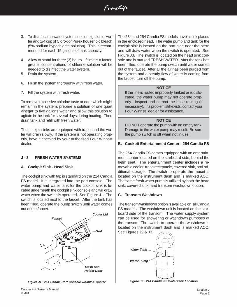
Section JPage 2
Candia FS Owner’s Manual03/00
The 234 and 254 Candia FS models have a sink placedin the enclosed head. The water pump and tank for thecockpit sink is located on the port side near the sternand will draw water when the switch is operated. SeeFigure J3. The switch is located on the head sink con-sole and is marked FRESH WATER. After the tank hasbeen filled, operate the pump switch until water comesout of the faucet. After all the air has been purged fromthe system and a steady flow of water is coming fromthe faucet, turn off the pump.
NOTICEIf the line is routed improperly, kinked or is dislo-cated, the water pump may not operate prop-erly. Inspect and correct the hose routing (ifnecessary). If a problem still exists, contact yourFour Winns® dealer for assistance.
NOTICEDO NOT operate the pump with an empty tank.Damage to the water pump may result. Be surethe pump switch is off when not in use.
B. Cockpit Entertainment Center - 254 Candia FS
The 254 Candia FS comes equipped with an entertain-ment center located on the starboard side, behind thehelm seat. The entertainment center includes a re-movable cooler, trash receptacle, covered sink, and ad-ditional storage. The switch to operate the faucet islocated on the instrument dash and is marked ACC.The same fresh water pump is utilized by both the headsink, covered sink, and transom washdown option.
C. Transom Washdown
The transom washdown option is available on all CandiaFS models. The washdown unit is located on the star-board side of the transom. The water supply systemcan be used for showering or washdown purposes atthe transom. The switch to operate the washdown islocated on the instrument dash and is marked ACC.See Figures J2 & J3.
3. To disinfect the water system, use one gallon of wa-ter and 1/4 cup of Clorox or Purex household bleach(5% sodium hypochlorite solution). This is recom-mended for each 15 gallons of tank capacity.
4. Allow to stand for three (3) hours. If time is a factor,greater concentrations of chlorine solution will beneeded to disinfect the water system.
5. Drain the system.
6. Flush the system thoroughly with fresh water.
7. Fill the system with fresh water.
To remove excessive chlorine taste or odor which mightremain in the system, prepare a solution of one quartvinegar to five gallons water and allow this solution toagitate in the tank for several days during boating. Thendrain tank and refill with fresh water.
The cockpit sinks are equipped with traps, and the wa-ter will drain slowly. If the system is not operating prop-erly, have it checked by your authorized Four Winns®dealer.
J - 3 FRESH WATER SYSTEMS
A. Cockpit Sink - Head Sink
The cockpit sink with tap is standard on the 214 CandiaFS model. It is integrated into the port console. Thewater pump and water tank for the cockpit sink is lo-cated underneath the cockpit sink console and will drawwater when the switch is operated. See Figure J1. Theswitch is located next to the faucet. After the tank hasbeen filled, operate the pump switch until water comesout of the faucet.
Figure J1: 214 Candia Port Console w/Sink & Cooler
Water Tank
Water Pump
Faucet
Trash CanHolder Door
Sink
Cooler LId
Figure J2: 214 Candia FS WaterTank Location
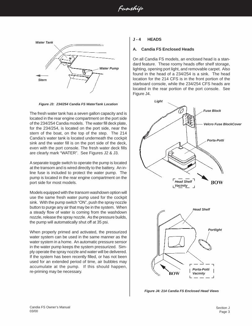
Section JPage 3
Candia FS Owner’s Manual03/00
Figure J3: 234/254 Candia FS WaterTank Location
The fresh water tank has a seven gallon capacity and islocated in the rear engine compartment on the port sideof the 234/254 Candia models. The water fill deck plate,for the 234/254, is located on the port side, near thestern of the boat, on the top of the step. The 214Candia’s water tank is located underneath the cockpitsink and the water fill is on the port side of the deck,even with the port console. The fresh water deck fillsare clearly mark “WATER”. See Figures J2 & J3.
A separate toggle switch to operate the pump is locatedat the transom and is wired directly to the battery. An in-line fuse is included to protect the water pump. Thepump is located in the rear engine compartment on theport side for most models.
Models equipped with the transom washdown option willuse the same fresh water pump used for the cockpitsink. With the pump switch “ON”, push the spray nozzlebutton to purge any air that may be in the system. Whena steady flow of water is coming from the washdownnozzle, release the spray nozzle. As the pressure builds,the pump will automatically shut off at 35 psi.
When properly primed and activated, the pressurizedwater system can be used in the same manner as thewater system in a home. An automatic pressure sensorin the water pump keeps the system pressurized. Sim-ply operate the spray nozzle and water will be delivered.If the system has been recently filled, or has not beenused for an extended period of time, air bubbles mayaccumulate at the pump. If this should happen,re-priming may be necessary.
J - 4 HEADS
A. Candia FS Enclosed Heads
On all Candia FS models, an enclosed head is a stan-dard feature. These roomy heads offer shelf storage,lighting, opening port light, and removable carpet. Alsofound in the head of a 234/254 is a sink. The headlocation for the 214 CFS is in the front portion of thestarboard console, while the 234/254 CFS heads arelocated in the rear portion of the port console. SeeFigure J4.
Water Tank
Water Pump
Light
Fuse Block
Porta-Potti
Head Shelf
Portlight
Velcro Fuse BlockCover
Porta-PottiVacinity
Head ShelfVacinity
Stern
Figure J4: 214 Candia FS Enclosed Head Views
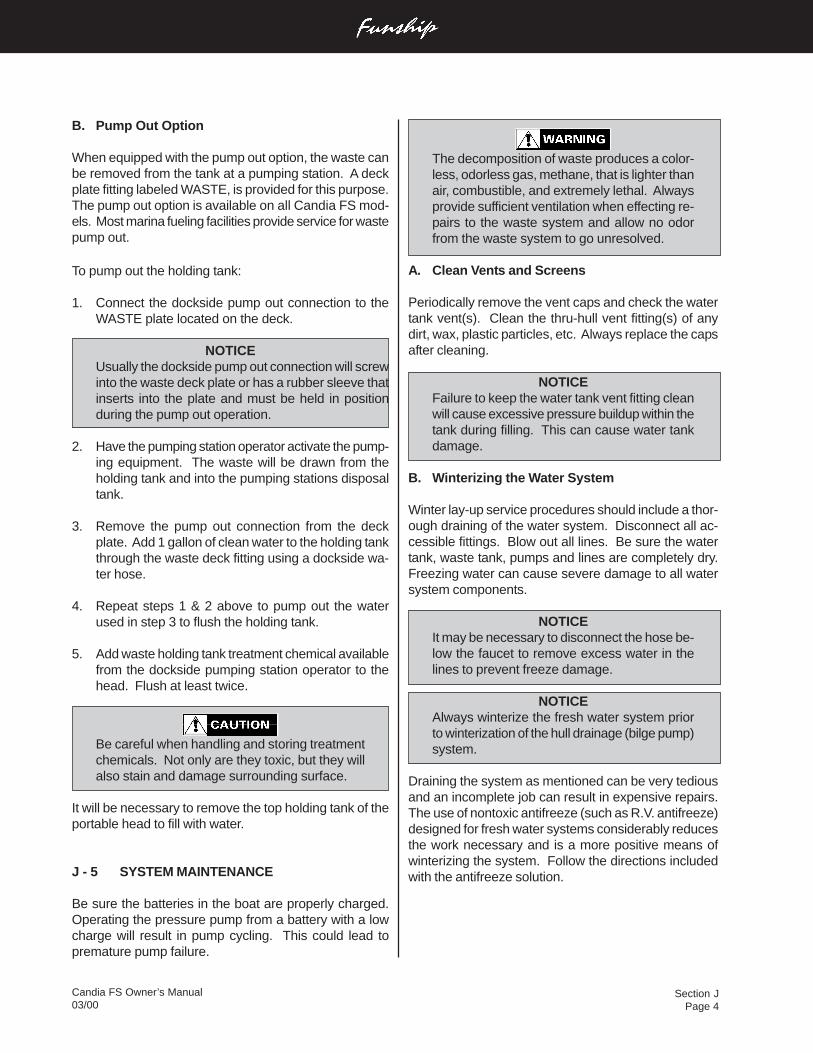
Section JPage 4
Candia FS Owner’s Manual03/00
B. Pump Out Option
When equipped with the pump out option, the waste canbe removed from the tank at a pumping station. A deckplate fitting labeled WASTE, is provided for this purpose.The pump out option is available on all Candia FS mod-els. Most marina fueling facilities provide service for wastepump out.
To pump out the holding tank:
1. Connect the dockside pump out connection to theWASTE plate located on the deck.
NOTICEUsually the dockside pump out connection will screwinto the waste deck plate or has a rubber sleeve thatinserts into the plate and must be held in positionduring the pump out operation.
2. Have the pumping station operator activate the pump-ing equipment. The waste will be drawn from theholding tank and into the pumping stations disposaltank.
3. Remove the pump out connection from the deckplate. Add 1 gallon of clean water to the holding tankthrough the waste deck fitting using a dockside wa-ter hose.
4. Repeat steps 1 & 2 above to pump out the waterused in step 3 to flush the holding tank.
5. Add waste holding tank treatment chemical availablefrom the dockside pumping station operator to thehead. Flush at least twice.
Be careful when handling and storing treatmentchemicals. Not only are they toxic, but they willalso stain and damage surrounding surface.
It will be necessary to remove the top holding tank of theportable head to fill with water.
J - 5 SYSTEM MAINTENANCE
Be sure the batteries in the boat are properly charged.Operating the pressure pump from a battery with a lowcharge will result in pump cycling. This could lead topremature pump failure.
The decomposition of waste produces a color-less, odorless gas, methane, that is lighter thanair, combustible, and extremely lethal. Alwaysprovide sufficient ventilation when effecting re-pairs to the waste system and allow no odorfrom the waste system to go unresolved.
A. Clean Vents and Screens
Periodically remove the vent caps and check the watertank vent(s). Clean the thru-hull vent fitting(s) of anydirt, wax, plastic particles, etc. Always replace the capsafter cleaning.
NOTICEFailure to keep the water tank vent fitting cleanwill cause excessive pressure buildup within thetank during filling. This can cause water tankdamage.
B. Winterizing the Water System
Winter lay-up service procedures should include a thor-ough draining of the water system. Disconnect all ac-cessible fittings. Blow out all lines. Be sure the watertank, waste tank, pumps and lines are completely dry.Freezing water can cause severe damage to all watersystem components.
NOTICEIt may be necessary to disconnect the hose be-low the faucet to remove excess water in thelines to prevent freeze damage.
NOTICEAlways winterize the fresh water system priorto winterization of the hull drainage (bilge pump)system.
Draining the system as mentioned can be very tediousand an incomplete job can result in expensive repairs.The use of nontoxic antifreeze (such as R.V. antifreeze)designed for fresh water systems considerably reducesthe work necessary and is a more positive means ofwinterizing the system. Follow the directions includedwith the antifreeze solution.
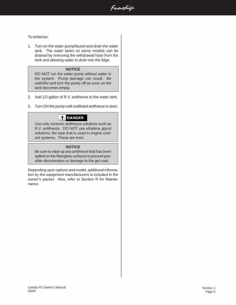
Section JPage 5
Candia FS Owner’s Manual03/00
To winterize:
1. Turn on the water pump/faucet and drain the watertank. The water tanks on some models can bedrained by removing the withdrawal hose from thetank and allowing water to drain into the bilge.
NOTICEDO NOT run the water pump without water inthe system. Pump damage can result. Bewatchful and turn the pump off as soon as thetank becomes empty.
2. Add 1/2 gallon of R.V. antifreeze to the water tank.
3. Turn ON the pump until undiluted antifreeze is seen.
Use only nontoxic antifreeze solutions such asR.V. antifreeze. DO NOT use ethylene glycolsolutions; the type that is used in engine cool-ant systems. These are toxic.
NOTICEBe sure to wipe up any antifreeze that has beenspilled on the fiberglass surfaces to prevent pos-sible discoloration or damage to the gel coat.
Depending upon options and model, additional informa-tion by the equipment manufacturers is included in theowner’s packet. Also, refer to Section R for Mainte-nance.
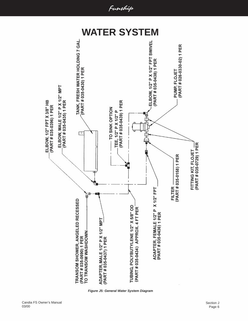
Section JPage 6
Candia FS Owner’s Manual03/00
Figure J5: General Water System Diagram
WATER SYSTEM
Section KPage 1
Candia FS Owner’s Manual03/00
C. Engine Ventilation System Maintenance
Periodic inspection and cleaning of the ventilation ductsis necessary to ensure adequate air circulation. A buildupof leaves, twigs, or other debris can severely reduceventilation. Be sure bilge water does not accumulate toa level that would obstruct the ventilation ducts.
Blower operation can be tested by placing a hand overthe vents. DO NOT rely on the sound of the blower. Besure a substantial amount of air is being exhausted bythe bilge blower. Check the bilge blower system often,preferably before each cruise.
Should blower noise and vibration be excessive, loos-ening the bilge blower mounting screws and then tight-ening evenly usually reduces noise considerably.
K - 2 HULL DRAINAGE SYSTEMS
A. Transom Drain
A transom drain with plug is provided in the engine com-partment to allow water drainage. When the boat is outof the water, the boat and trailer should be positioned soany bilge water accumulation during dry storage will flowtowards the transom.
Be sure the drain plug is securely in place priorto launching the boat. Upon shipment of theboat, the drain plug is usually taped to the steer-ing wheel.
B. Bilge Pumps
Bilge pumps are provided in the bottom of the hull toremove miscellaneous water accumulations that mightoccur during normal boating or weather conditions. Thebilge pump is controlled by the Bilge Pump Switch onthe dash panel. See Section H-3 for a detailed descrip-tion of the bilge pump switches.
VENTILATION & DRAINAGE SYSTEMS
K - 1 ENGINE COMPARTMENT VENTILATION
All Four Winns® stern drive models are equipped withengine compartment ventilation. This system is designedto meet or exceed the requirements (in effect at the timeof manufacture) of the U.S. Coast Guard, the NationalMarine Manufacturers Association, and the AmericanBoat and Yacht Council.
A. Gravity Ventilation System
This system includes air intake and exhaust components.The exhaust ducting reaches to the lower bilge area.This provides adequate air movement while underwayand during bilge blower operation.
B. Forced Air Ventilation
All Four Winns® models except outboards are equippedwith an electric bilge blower. The bilge blower providesthe ventilation required prior to starting the engines andwhile at idle. See Section H Electrical Systems for bloweroperation instructions.
Gasoline vapors can explode resulting in in-jury or death. Before starting the engine, checkthe engine compartment bilge for gasoline orvapors, and operate blower for four (4) minutes,and verify blower operation. Run blower whenvessel is operating below cruising speed. AL-WAYS operate the bilge blower while the en-gines are at idle.
NOTICEA Gas Vapor Detector is a monitor which willalert the operator of an accumulation of gaso-line fumes in the engine compartment. It is op-tional only on larger models but can be installedby your Four Winns® dealer. DO NOT rely solelyon detectors or similar equipment. ALWAYSconduct a physical inspection of the enginecompartment.
Section KPage 2
Candia FS Owner’s Manual03/00
Bilge pumps equipped with automatic switches are stan-dard on all Candia FS models. As the water level rises,the automatic float switch will activate the pump.
When leaving the boat unattended for long periods oftime or during excessive rain storms, it is a good idea tocheck on the boat for excessive water accumulation. Besure the bilge pump and automatic float switch (ifequipped) are operating properly. The operating time ofthe bilge pump will be limited to the battery capacity.
NOTICEWhile at rest, any bilge water accumulation mayflow forward. Therefore, operate the bilge pumpshortly after getting underway and while the boatis at a substantial running angle. DO NOT al-low bilge water to accumulate. Damage to theengine or other components may result.
Periodically, clean the bilge pump strainers. DO NOTallow dirt and debris to clog the bilge pump intakes.Check operation of the bilge pump float switch often toensure movement of the switch is not restricted by de-bris, portions of the hull, etc.
Wipe up any oil accumulation in the bilge prior to activa-tion of the bilge pump. Pumping oil overboard will pol-lute the water, and is subject to fine.
After winterization of the fresh water systems, be surethe bilge area, bilge pump and associated hoses arethoroughly dry. Damage to the hull, bilge pump and otherequipment could occur if water is allowed to freeze inthe bilge.
C. Liner Drains
Liner drains are provided on models with fiberglass lin-ers or floors. Fiberglass liners can be cleaned easily byhosing the floor. The water will drain into the bilge andbe pumped overboard.
D. Bilge Compartment Drainage
Certain bulkhead areas of Four Winns® boats are sealedin accordance with U.S. Coast Guard regulations effec-tive at the date of manufacture. Drainage is providedand water can be removed with the bilge pump.
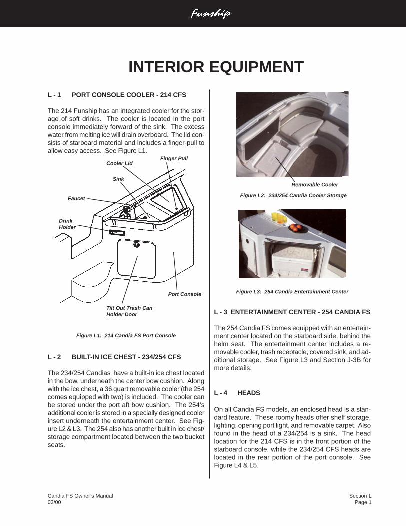
Candia FS Owner’s Manual03/00
Section LPage 1
L - 1 PORT CONSOLE COOLER - 214 CFS
The 214 Funship has an integrated cooler for the stor-age of soft drinks. The cooler is located in the portconsole immediately forward of the sink. The excesswater from melting ice will drain overboard. The lid con-sists of starboard material and includes a finger-pull toallow easy access. See Figure L1.
Figure L1: 214 Candia FS Port Console
L - 2 BUILT-IN ICE CHEST - 234/254 CFS
The 234/254 Candias have a built-in ice chest locatedin the bow, underneath the center bow cushion. Alongwith the ice chest, a 36 quart removable cooler (the 254comes equipped with two) is included. The cooler canbe stored under the port aft bow cushion. The 254’sadditional cooler is stored in a specially designed coolerinsert underneath the entertainment center. See Fig-ure L2 & L3. The 254 also has another built in ice chest/storage compartment located between the two bucketseats.
INTERIOR EQUIPMENT
Faucet
Tilt Out Trash CanHolder Door
Sink
Cooler LId
Port Console
DrinkHolder
Finger Pull
L - 3 ENTERTAINMENT CENTER - 254 CANDIA FS
The 254 Candia FS comes equipped with an entertain-ment center located on the starboard side, behind thehelm seat. The entertainment center includes a re-movable cooler, trash receptacle, covered sink, and ad-ditional storage. See Figure L3 and Section J-3B formore details.
L - 4 HEADS
On all Candia FS models, an enclosed head is a stan-dard feature. These roomy heads offer shelf storage,lighting, opening port light, and removable carpet. Alsofound in the head of a 234/254 is a sink. The headlocation for the 214 CFS is in the front portion of thestarboard console, while the 234/254 CFS heads arelocated in the rear portion of the port console. SeeFigure L4 & L5.
Removable Cooler
Figure L2: 234/254 Candia Cooler Storage
Figure L3: 254 Candia Entertainment Center
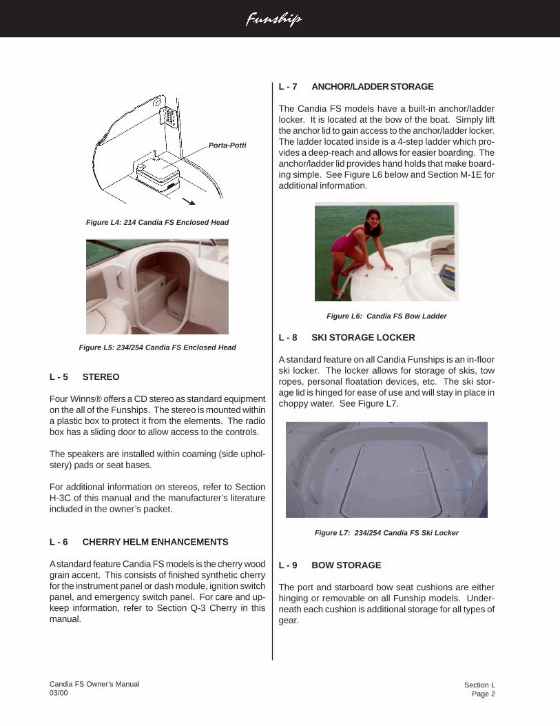
Section LPage 2
Candia FS Owner’s Manual03/00
Figure L4: 214 Candia FS Enclosed Head
Figure L5: 234/254 Candia FS Enclosed Head
L - 5 STEREO
Four Winns® offers a CD stereo as standard equipmenton the all of the Funships. The stereo is mounted withina plastic box to protect it from the elements. The radiobox has a sliding door to allow access to the controls.
The speakers are installed within coaming (side uphol-stery) pads or seat bases.
For additional information on stereos, refer to SectionH-3C of this manual and the manufacturer’s literatureincluded in the owner’s packet.
L - 6 CHERRY HELM ENHANCEMENTS
A standard feature Candia FS models is the cherry woodgrain accent. This consists of finished synthetic cherryfor the instrument panel or dash module, ignition switchpanel, and emergency switch panel. For care and up-keep information, refer to Section Q-3 Cherry in thismanual.
L - 7 ANCHOR/LADDER STORAGE
The Candia FS models have a built-in anchor/ladderlocker. It is located at the bow of the boat. Simply liftthe anchor lid to gain access to the anchor/ladder locker.The ladder located inside is a 4-step ladder which pro-vides a deep-reach and allows for easier boarding. Theanchor/ladder lid provides hand holds that make board-ing simple. See Figure L6 below and Section M-1E foradditional information.
Figure L6: Candia FS Bow Ladder
L - 8 SKI STORAGE LOCKER
A standard feature on all Candia Funships is an in-floorski locker. The locker allows for storage of skis, towropes, personal floatation devices, etc. The ski stor-age lid is hinged for ease of use and will stay in place inchoppy water. See Figure L7.
Figure L7: 234/254 Candia FS Ski Locker
L - 9 BOW STORAGE
The port and starboard bow seat cushions are eitherhinging or removable on all Funship models. Under-neath each cushion is additional storage for all types ofgear.
Porta-Potti
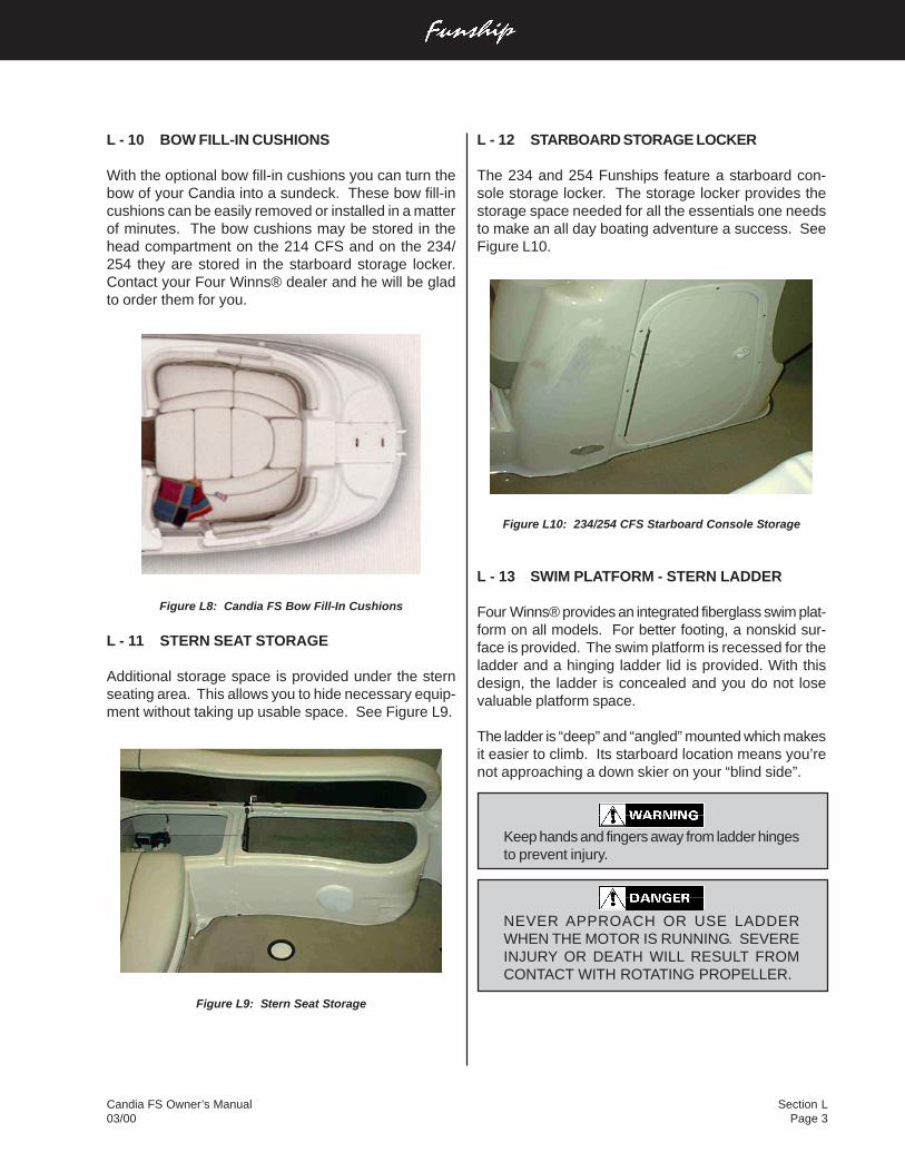
Candia FS Owner’s Manual03/00
Section LPage 3
L - 10 BOW FILL-IN CUSHIONS
With the optional bow fill-in cushions you can turn thebow of your Candia into a sundeck. These bow fill-incushions can be easily removed or installed in a matterof minutes. The bow cushions may be stored in thehead compartment on the 214 CFS and on the 234/254 they are stored in the starboard storage locker.Contact your Four Winns® dealer and he will be gladto order them for you.
Figure L8: Candia FS Bow Fill-In Cushions
L - 11 STERN SEAT STORAGE
Additional storage space is provided under the sternseating area. This allows you to hide necessary equip-ment without taking up usable space. See Figure L9.
Figure L9: Stern Seat Storage
L - 12 STARBOARD STORAGE LOCKER
The 234 and 254 Funships feature a starboard con-sole storage locker. The storage locker provides thestorage space needed for all the essentials one needsto make an all day boating adventure a success. SeeFigure L10.
Figure L10: 234/254 CFS Starboard Console Storage
L - 13 SWIM PLATFORM - STERN LADDER
Four Winns® provides an integrated fiberglass swim plat-form on all models. For better footing, a nonskid sur-face is provided. The swim platform is recessed for theladder and a hinging ladder lid is provided. With thisdesign, the ladder is concealed and you do not losevaluable platform space.
The ladder is “deep” and “angled” mounted which makesit easier to climb. Its starboard location means you’renot approaching a down skier on your “blind side”.
Keep hands and fingers away from ladder hingesto prevent injury.
NEVER APPROACH OR USE LADDERWHEN THE MOTOR IS RUNNING. SEVEREINJURY OR DEATH WILL RESULT FROMCONTACT WITH ROTATING PROPELLER.
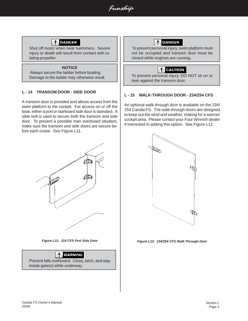
Section LPage 4
Candia FS Owner’s Manual03/00
To prevent personal injury, swim platform mustnot be occupied and transom door must beclosed while engines are running.
To prevent personal injury, DO NOT sit on orlean against the transom door.
L - 15 WALK-THROUGH DOOR - 234/254 CFS
An optional walk-through door is available on the 234/254 Candia FS. The walk-through doors are designedto keep out the wind and weather, making for a warmercockpit area. Please contact your Four Winns® dealerif interested in adding this option. See Figure L12.
Figure L12: 234/254 CFS Walk-Through Door
Shut off motor when near swimmers. Severeinjury or death will result from contact with ro-tating propeller.
NOTICE Always secure the ladder before boating.Damage to the ladder may otherwise result.
L - 14 TRANSOM DOOR - SIDE DOOR
A transom door is provided and allows access from theswim platform to the cockpit. For access on or off theboat, either a port or starboard side door is standard. Aslide bolt is used to secure both the transom and sidedoor. To prevent a possible man overboard situation,make sure the transom and side doors are secure be-fore each cruise. See Figure L11.
Figure L11: 214 CFS Port Side Door
Prevent falls overboard. Close, latch, and stayinside gate(s) while underway.
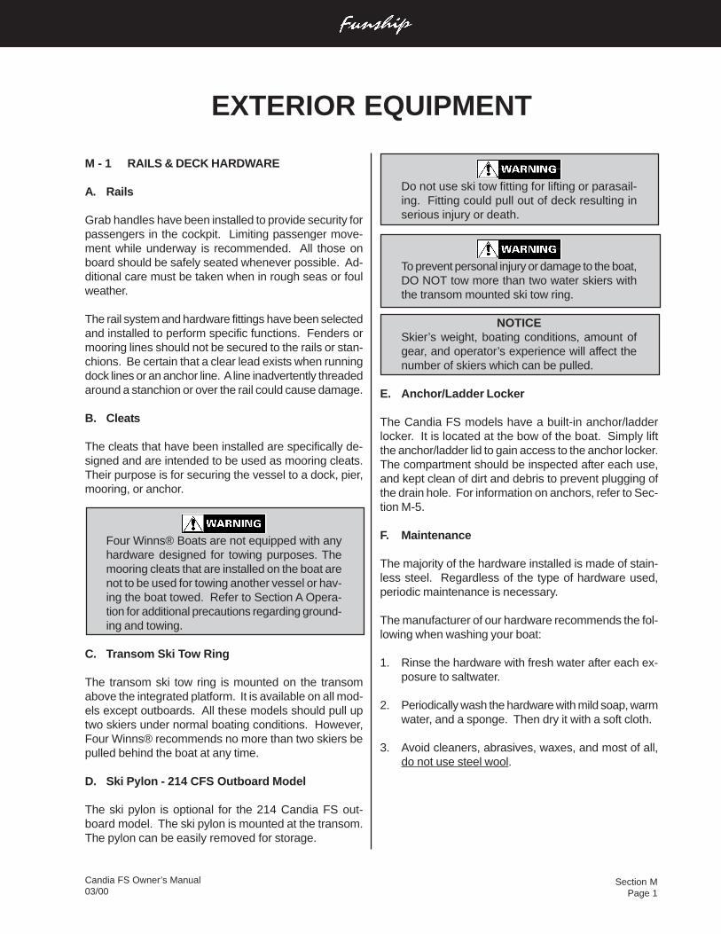
Section MPage 1
Candia FS Owner’s Manual03/00
M - 1 RAILS & DECK HARDWARE
A. Rails
Grab handles have been installed to provide security forpassengers in the cockpit. Limiting passenger move-ment while underway is recommended. All those onboard should be safely seated whenever possible. Ad-ditional care must be taken when in rough seas or foulweather.
The rail system and hardware fittings have been selectedand installed to perform specific functions. Fenders ormooring lines should not be secured to the rails or stan-chions. Be certain that a clear lead exists when runningdock lines or an anchor line. A line inadvertently threadedaround a stanchion or over the rail could cause damage.
B. Cleats
The cleats that have been installed are specifically de-signed and are intended to be used as mooring cleats.Their purpose is for securing the vessel to a dock, pier,mooring, or anchor.
Four Winns® Boats are not equipped with anyhardware designed for towing purposes. Themooring cleats that are installed on the boat arenot to be used for towing another vessel or hav-ing the boat towed. Refer to Section A Opera-tion for additional precautions regarding ground-ing and towing.
C. Transom Ski Tow Ring
The transom ski tow ring is mounted on the transomabove the integrated platform. It is available on all mod-els except outboards. All these models should pull uptwo skiers under normal boating conditions. However,Four Winns® recommends no more than two skiers bepulled behind the boat at any time.
D. Ski Pylon - 214 CFS Outboard Model
The ski pylon is optional for the 214 Candia FS out-board model. The ski pylon is mounted at the transom.The pylon can be easily removed for storage.
EXTERIOR EQUIPMENT
Do not use ski tow fitting for lifting or parasail-ing. Fitting could pull out of deck resulting inserious injury or death.
To prevent personal injury or damage to the boat,DO NOT tow more than two water skiers withthe transom mounted ski tow ring.
NOTICESkier’s weight, boating conditions, amount ofgear, and operator’s experience will affect thenumber of skiers which can be pulled.
E. Anchor/Ladder Locker
The Candia FS models have a built-in anchor/ladderlocker. It is located at the bow of the boat. Simply liftthe anchor/ladder lid to gain access to the anchor locker.The compartment should be inspected after each use,and kept clean of dirt and debris to prevent plugging ofthe drain hole. For information on anchors, refer to Sec-tion M-5.
F. Maintenance
The majority of the hardware installed is made of stain-less steel. Regardless of the type of hardware used,periodic maintenance is necessary.
The manufacturer of our hardware recommends the fol-lowing when washing your boat:
1. Rinse the hardware with fresh water after each ex-posure to saltwater.
2. Periodically wash the hardware with mild soap, warmwater, and a sponge. Then dry it with a soft cloth.
3. Avoid cleaners, abrasives, waxes, and most of all,do not use steel wool.
Section MPage 2
Candia FS Owner’s Manual03/00
NOTICEAll fittings must be periodically inspected for loos-ening, wear, and damage. Problems should becorrected immediately!
M - 2 WINDSCREENS & WINDSHIELDS
Depending on the model, a windscreen or windshield isstandard equipment. The 214 has a plexiglasswindscreen on the driver’s console. The 234/254 hasa full windshield consisting of tempered safety glass andthe windshield frame is aluminum.
Plexiglass windscreens and windshields of temperedglass can be cleaned with automotive glass cleaners ordishwashing soap and water. Ensure that a clean clothis used to prevent scratching the plexiglass.
Aluminum can be cleaned with similar products or withnonabrasive cleaners such as Fantastik™.
NOTICERead the label before using any product. DONOT use abrasive cleaners.
M - 3 SWIM PLATFORM
Four Winns® provides an integrated fiberglass swim plat-form on all models. For better footing, a nonskid sur-face is provided. The ladder is “deep” and “angled”mounted which makes it easier to climb. Its starboardlocation means you’re not approaching a down skieron your “blind side”.
Keep hands and fingers away from ladder hingesto prevent injury.
NEVER APPROACH OR USE LADDERWHEN THE MOTOR IS RUNNING. SEVEREINJURY OR DEATH WILL RESULT FROMCONTACT WITH ROTATING PROPELLER.
Shut off motor when near swimmers. Severeinjury or death will result from contact with ro-tating propeller.
NOTICE Always secure the ladder before boating.Damage to the ladder may otherwise result.
M - 4 TRANSOM DOOR - SIDE DOOR
A transom door is provided and allows access from theswim platform to the cockpit. For access on or off theboat, either a port or starboard side door is standard. Aslide bolt is used to secure both the transom and sidedoor. To prevent a possible man overboard situation,make sure the transom and side doors are secure be-fore each cruise.
Prevent falls overboard. Close, latch, and stayinside gate(s) while underway.
To prevent personal injury, swim platform mustnot be occupied and transom door must beclosed while engines are running.
To prevent personal injury, DO NOT sit on orlean against the transom door.
M - 5 ANCHOR
Four Winns® recommends an eight (8) pound, Attwood®“Penetrating” anchor, with a 3/8” line be used on all theCandia FS models. The recommended line length is100-150 feet. Because of differences in style, a largeranchor may be needed for different bottom or boatingconditions.
NOTICEA “system matched*” fluke style anchor fits inall applications. *”System matched” means thatthe designated OEM part, anchors in this in-stance, found in an OEM parts catalog wouldwork in this application.
Anchors are usually a dealer installed option. Pleasecheck with your Four Winns® dealer for his recommen-dations.
Section MPage 3
Candia FS Owner’s Manual03/00
M - 6 DEPTHSOUNDER
The depthsounder is standard equipment on all theCandia FS models The depthsounder has both au-dible and visual alarms. See Sections E-6H - E-6J ofthis manual for additional information.
Do not rely on depthsounder to avoid sub-merged objects. Depth sounders provide a rela-tive indication of water depth only.
NOTICEDO NOT depend solely upon the depthsounderfor water depth. It is important to havenavigational charts of the waters in which youare operating.
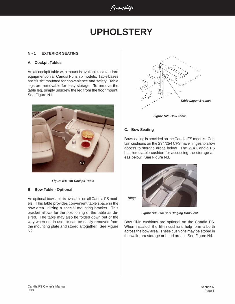
Section NPage 1
Candia FS Owner’s Manual03/00
Figure N2: Bow Table
C. Bow Seating
Bow seating is provided on the Candia FS models. Cer-tain cushions on the 234/254 CFS have hinges to allowaccess to storage areas below. The 214 Candia FShas removable cushion for accessing the storage ar-eas below. See Figure N3.
Figure N3: 254 CFS Hinging Bow Seat
Bow fill-in cushions are optional on the Candia FS.When installed, the fill-in cushions help form a berthacross the bow area. These cushions may be stored inthe walk-thru storage or head areas. See Figure N4.
N - 1 EXTERIOR SEATING
A. Cockpit Tables
An aft cockpit table with mount is available as standardequipment on all Candia Funship models. Table basesare “flush” mounted for convenience and safety. Tablelegs are removable for easy storage. To remove thetable leg, simply unscrew the leg from the floor mount.See Figure N1.
Figure N1: Aft Cockpit Table
B. Bow Table - Optional
An optional bow table is available on all Candia FS mod-els. This table provides convenient table space in thebow area utilizing a special mounting bracket. Thisbracket allows for the positioning of the table as de-sired. The table may also be folded down out of theway when not in use, or can be easily removed fromthe mounting plate and stored altogether. See FigureN2.
UPHOLSTERY
Table Lagun Bracket
Hinge
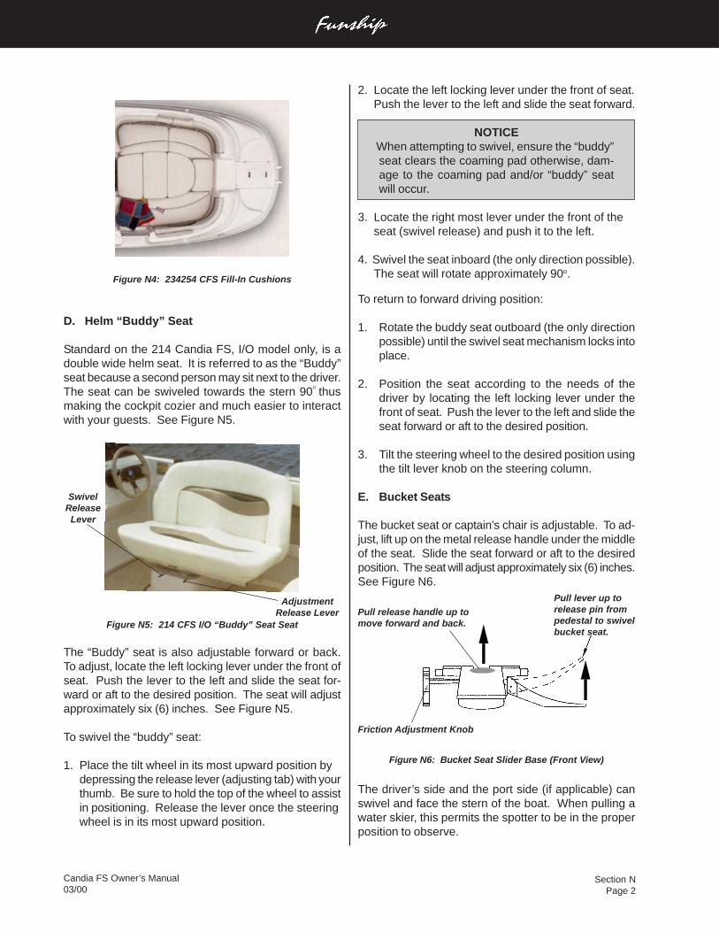
Section NPage 2
Candia FS Owner’s Manual03/00
2. Locate the left locking lever under the front of seat.Push the lever to the left and slide the seat forward.
NOTICE When attempting to swivel, ensure the “buddy”seat clears the coaming pad otherwise, dam-age to the coaming pad and/or “buddy” seatwill occur.
3. Locate the right most lever under the front of theseat (swivel release) and push it to the left.
4. Swivel the seat inboard (the only direction possible).The seat will rotate approximately 90o.
To return to forward driving position:
1. Rotate the buddy seat outboard (the only directionpossible) until the swivel seat mechanism locks intoplace.
2. Position the seat according to the needs of thedriver by locating the left locking lever under thefront of seat. Push the lever to the left and slide theseat forward or aft to the desired position.
3. Tilt the steering wheel to the desired position usingthe tilt lever knob on the steering column.
E. Bucket Seats
The bucket seat or captain’s chair is adjustable. To ad-just, lift up on the metal release handle under the middleof the seat. Slide the seat forward or aft to the desiredposition. The seat will adjust approximately six (6) inches.See Figure N6.
Figure N6: Bucket Seat Slider Base (Front View)
The driver’s side and the port side (if applicable) canswivel and face the stern of the boat. When pulling awater skier, this permits the spotter to be in the properposition to observe.
Figure N4: 234254 CFS Fill-In Cushions
D. Helm “Buddy” Seat
Standard on the 214 Candia FS, I/O model only, is adouble wide helm seat. It is referred to as the “Buddy”seat because a second person may sit next to the driver.The seat can be swiveled towards the stern 90O thusmaking the cockpit cozier and much easier to interactwith your guests. See Figure N5.
Figure N5: 214 CFS I/O “Buddy” Seat Seat
The “Buddy” seat is also adjustable forward or back.To adjust, locate the left locking lever under the front ofseat. Push the lever to the left and slide the seat for-ward or aft to the desired position. The seat will adjustapproximately six (6) inches. See Figure N5.
To swivel the “buddy” seat:
1. Place the tilt wheel in its most upward position bydepressing the release lever (adjusting tab) with yourthumb. Be sure to hold the top of the wheel to assistin positioning. Release the lever once the steeringwheel is in its most upward position.
Pull release handle up tomove forward and back.
Pull lever up torelease pin frompedestal to swivelbucket seat.
Friction Adjustment Knob
SwivelReleaseLever
AdjustmentRelease Lever
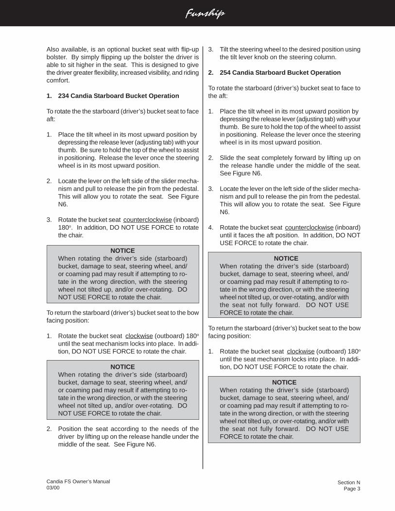
Section NPage 3
Candia FS Owner’s Manual03/00
3. Tilt the steering wheel to the desired position usingthe tilt lever knob on the steering column.
2. 254 Candia Starboard Bucket Operation
To rotate the starboard (driver’s) bucket seat to face tothe aft:
1. Place the tilt wheel in its most upward position bydepressing the release lever (adjusting tab) with yourthumb. Be sure to hold the top of the wheel to assistin positioning. Release the lever once the steeringwheel is in its most upward position.
2. Slide the seat completely forward by lifting up onthe release handle under the middle of the seat.See Figure N6.
3. Locate the lever on the left side of the slider mecha-nism and pull to release the pin from the pedestal.This will allow you to rotate the seat. See FigureN6.
4. Rotate the bucket seat counterclockwise (inboard)until it faces the aft position. In addition, DO NOTUSE FORCE to rotate the chair.
NOTICEWhen rotating the driver’s side (starboard)bucket, damage to seat, steering wheel, and/or coaming pad may result if attempting to ro-tate in the wrong direction, or with the steeringwheel not tilted up, or over-rotating, and/or withthe seat not fully forward. DO NOT USEFORCE to rotate the chair.
To return the starboard (driver’s) bucket seat to the bowfacing position:
1. Rotate the bucket seat clockwise (outboard) 180o
until the seat mechanism locks into place. In addi-tion, DO NOT USE FORCE to rotate the chair.
NOTICEWhen rotating the driver’s side (starboard)bucket, damage to seat, steering wheel, and/or coaming pad may result if attempting to ro-tate in the wrong direction, or with the steeringwheel not tilted up, or over-rotating, and/or withthe seat not fully forward. DO NOT USEFORCE to rotate the chair.
Also available, is an optional bucket seat with flip-upbolster. By simply flipping up the bolster the driver isable to sit higher in the seat. This is designed to givethe driver greater flexibility, increased visibility, and ridingcomfort.
1. 234 Candia Starboard Bucket Operation
To rotate the the starboard (driver’s) bucket seat to faceaft:
1. Place the tilt wheel in its most upward position bydepressing the release lever (adjusting tab) with yourthumb. Be sure to hold the top of the wheel to assistin positioning. Release the lever once the steeringwheel is in its most upward position.
2. Locate the lever on the left side of the slider mecha-nism and pull to release the pin from the pedestal.This will allow you to rotate the seat. See FigureN6.
3. Rotate the bucket seat counterclockwise (inboard)180o. In addition, DO NOT USE FORCE to rotatethe chair.
NOTICEWhen rotating the driver’s side (starboard)bucket, damage to seat, steering wheel, and/or coaming pad may result if attempting to ro-tate in the wrong direction, with the steeringwheel not tilted up, and/or over-rotating. DONOT USE FORCE to rotate the chair.
To return the starboard (driver’s) bucket seat to the bowfacing position:
1. Rotate the bucket seat clockwise (outboard) 180o
until the seat mechanism locks into place. In addi-tion, DO NOT USE FORCE to rotate the chair.
NOTICEWhen rotating the driver’s side (starboard)bucket, damage to seat, steering wheel, and/or coaming pad may result if attempting to ro-tate in the wrong direction, or with the steeringwheel not tilted up, and/or over-rotating. DONOT USE FORCE to rotate the chair.
2. Position the seat according to the needs of thedriver by lifting up on the release handle under themiddle of the seat. See Figure N6.
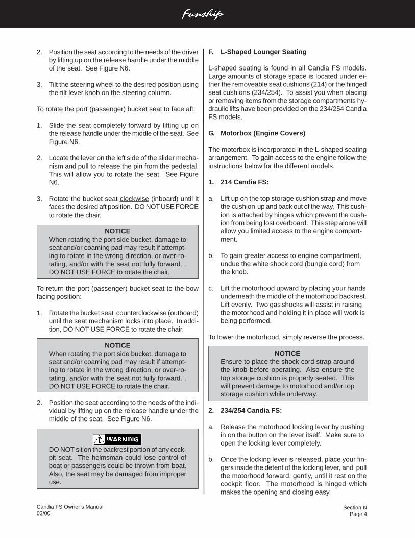
Section NPage 4
Candia FS Owner’s Manual03/00
F. L-Shaped Lounger Seating
L-shaped seating is found in all Candia FS models.Large amounts of storage space is located under ei-ther the removeable seat cushions (214) or the hingedseat cushions (234/254). To assist you when placingor removing items from the storage compartments hy-draulic lifts have been provided on the 234/254 CandiaFS models.
G. Motorbox (Engine Covers)
The motorbox is incorporated in the L-shaped seatingarrangement. To gain access to the engine follow theinstructions below for the different models.
1. 214 Candia FS:
a. Lift up on the top storage cushion strap and movethe cushion up and back out of the way. This cush-ion is attached by hinges which prevent the cush-ion from being lost overboard. This step alone willallow you limited access to the engine compart-ment.
b. To gain greater access to engine compartment,undue the white shock cord (bungie cord) fromthe knob.
c. Lift the motorhood upward by placing your handsunderneath the middle of the motorhood backrest.Lift evenly. Two gas shocks will assist in raisingthe motorhood and holding it in place will work isbeing performed.
To lower the motorhood, simply reverse the process.
NOTICEEnsure to place the shock cord strap aroundthe knob before operating. Also ensure thetop storage cushion is properly seated. Thiswill prevent damage to motorhood and/or topstorage cushion while underway.
2. 234/254 Candia FS:
a. Release the motorhood locking lever by pushingin on the button on the lever itself. Make sure toopen the locking lever completely.
b. Once the locking lever is released, place your fin-gers inside the detent of the locking lever, and pullthe motorhood forward, gently, until it rest on thecockpit floor. The motorhood is hinged whichmakes the opening and closing easy.
2. Position the seat according to the needs of the driverby lifting up on the release handle under the middleof the seat. See Figure N6.
3. Tilt the steering wheel to the desired position usingthe tilt lever knob on the steering column.
To rotate the port (passenger) bucket seat to face aft:
1. Slide the seat completely forward by lifting up onthe release handle under the middle of the seat. SeeFigure N6.
2. Locate the lever on the left side of the slider mecha-nism and pull to release the pin from the pedestal.This will allow you to rotate the seat. See FigureN6.
3. Rotate the bucket seat clockwise (inboard) until itfaces the desired aft position. DO NOT USE FORCEto rotate the chair.
NOTICEWhen rotating the port side bucket, damage toseat and/or coaming pad may result if attempt-ing to rotate in the wrong direction, or over-ro-tating, and/or with the seat not fully forward. .DO NOT USE FORCE to rotate the chair.
To return the port (passenger) bucket seat to the bowfacing position:
1. Rotate the bucket seat counterclockwise (outboard)until the seat mechanism locks into place. In addi-tion, DO NOT USE FORCE to rotate the chair.
NOTICEWhen rotating the port side bucket, damage toseat and/or coaming pad may result if attempt-ing to rotate in the wrong direction, or over-ro-tating, and/or with the seat not fully forward. .DO NOT USE FORCE to rotate the chair.
2. Position the seat according to the needs of the indi-vidual by lifting up on the release handle under themiddle of the seat. See Figure N6.
DO NOT sit on the backrest portion of any cock-pit seat. The helmsman could lose control ofboat or passengers could be thrown from boat.Also, the seat may be damaged from improperuse.
Section NPage 5
Candia FS Owner’s Manual03/00
To lower the motorhood, simply reverse the process.
NOTICEDo not allow the motorbox cover to “slam” shut.Gently guide the motorbox into the “closed” po-sition. Allowing the motorbox to “slam” shutcan damage the fiberglass motorbox.
NOTICEUpon closing, ensure to secure the motorhoodby placing the locking lever in the locked posi-tion by simply pushing down on the lever. Thiswill prevent the motorbox from vibrating andloosening the hinge screws.
NOTICENever operate your boat with the engine lid inits open position. Doing so could result in dam-age or loss of cushion and hardware. This isalso true when trailering your boat. Cushions,if not properly stored and secure, will blowout of the boat.
N - 2 EXTERIOR UPHOLSTERY CARE
The vinyl material used on the exterior upholstery canbe easily cleaned using mild detergent and water. Besure to thoroughly rinse the seats after washing to re-move all soap film. Periodic spraying of the seats withLysol Spray Disinfectant™ will help retard mildew.
NOTICEDO NOT apply vinyl protectants such asArmorall™. The manufacturer does not rec-ommend this product because it removes theoils present in vinyl that keeps vinyl soft.
A recommended “Cleaning Kit” includes:
• Ivory Dishwashing Liquid™ and water
• Clean, white towels
• Medium-soft brush
• Fantastik Spray Cleaner™
• Denatured Alcohol
• Tough Duty Cleaner™(to locate the nearest distributor, call 800-537-8990)
• Ammonia and hydrogen peroxide
To remove stains, follow the guidelines below.
1. Basic Stains/Grease/Pencil/Dirt:
Ivory Soap™ and water or Fantastik Spray Cleaner™applied with a medium-soft brush.
2. Tough Stains/Adhesive/Teak Oil/Rust:
Tough Duty Cleaner™, rinse with soap and water.
NOTICETo prevent possible damage to the vinyl, rinsewith soap and water after applying theTough DutyCleaner™.
3. Ink:
Denatured alcohol.
4. Mildew Stains:
To kill bacteria creating the mildew, vigorously brushthe stained area with a 4-to-1 mixture of water andammonia; rinse with water.
5. Tough Mildew Stains:
Apply a mixture of one (1) teaspoon ammonia, one-fourth (1/4) cup of hydrogen peroxide, and three-fourths (3/4) cup of distilled water; rinse with water.
NOTICEALWAYS CLEAN STAINS IMMEDIATELY! DONOT use 409 Cleaner™ or Armorall™ on vinyl.All cleaning methods must be followed by athorough rinse with water.
Certain household cleaners, powdered abrasives, steelwool and industrial cleaners can cause damage and dis-coloration and are not recommended. Dry cleaning flu-ids and lacquer solvent should not be used as they willremove the printed pattern and gloss. Waxes should beused with caution. May contain dyes or solvents that canpermanently damage the protective coating.
Additional cleaning information is provided by the manu-facturer and is included with this manual.
Four Winns® offers a variety of optional weather coversfor protection of the boat and associated equipment. Con-tinued exposure can damage the upholstery and seat-ing. The seating can become thoroughly saturated withwater if not adequately protected. Refer to Section O onWeather Covers for more information.
Section NPage 6
Candia FS Owner’s Manual03/00
NOTICEThe appearance and longevity of the exteriorupholstery will be affected by water saturation.Protect these items appropriately.
N - 3 REPLACEMENT UPHOLSTERY
Should upholstery become severely soiled, torn, or insome manner damaged, replacement upholstery cush-ions are available. Larger upholstery items have sepa-rate component parts for easier serviceability.
Depending upon the year and model of the boat, mostupholstery parts can be obtained through your FourWinns® servicing dealer within a short period of time.
N - 4 CARPET CARE
A. Interior and Exterior Carpet
Four Winns® Sport Boat models use a high quality gradecarpeting in the cabin and cockpit. Vacuuming and occa-sional rug shampooing are recommended for extendedlife and appearance. It is 100% UV stabilized Olefin™Polypropylene fiber.
The optional snap-in carpet for the cockpit with fiber-glass liner is also made of 100% UV stabilized Olefin™Polypropylene fiber. This is an exterior grade, high qual-ity carpet with rubber-type backing.
NOTICEDO NOT dry carpeting in an automatic dryer.
The snap-in carpet may be periodically washed with mildlaundry soaps or shampooed, dried and reinstalled. Ad-ditional information is listed below.
B. Cleaning and Maintenance
The following information should be useful in helping youkeep your carpet looking well maintained.
Carpet made with Olefin™ fiber possesses built-in stainand soil release for easy, less costly maintenance. Regu-lar vacuuming and occasional shampooing help it stayattractive and serviceable.
C. Stain Removal Testing
Even the most stubborn stains can be removed fromOlefin™ fiber following the procedures outlined. A totalof thirty-four stains were selected as being representa-
tive of spills commonly occurring on carpets. Stains werepressed into the carpet to simulate foot pressure follow-ing a spill. Stains were applied to a two-inch squaresection and allowed to penetrate. Removal was per-formed after two weeks. Carpets were tested for stainremoval by an independent laboratory. Stain removalwas effective for all 34 stains. Results are shown in thetable.
D. Stain Removal Procedure
Regular maintenance such as vacuuming, hosing orwashing should be performed. Most stains and mildeware easily removed from carpet made with Olefin™ fiberusing common household cleaners. Refer to Table I.Olefin™ fiber is so resistant to chemical attack that CloroxBleach™ may be used to clean up any mildew that mayresult from excessive wetness.
Code for stain removal procedure (See Table 1):
“A” Apply hot water and detergent.
“B” Apply volatile dry solvent, work with bone spatula,blot.
“C” Flush by hot water extraction.
Recommended reagents:
• Carpet detergent such as Mintex™ (Hydromaster®)or any carpet detergent suitable for hot water ex-traction.
• Volatile dry solvent such as Carbona™, Energene™,or Picrin™ (Street®).
• Oily type paint remover such as nail polish remover,Energene™ or Pyrotex™ (Street®).
• Neutral lubricant such as Streetex Spray Spotter™(Street®) or alternate treatment with detergent andEnergene™.
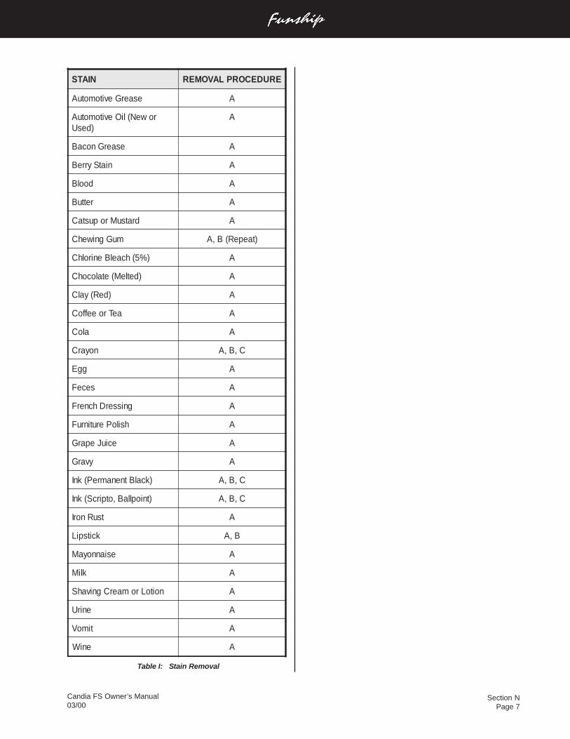
Section NPage 7
Candia FS Owner’s Manual03/00
NIATS ERUDECORPLAVOMER
esaerGevitomotuA A
roweN(liOevitomotuA)desU
A
esaerGnocaB A
niatSyrreB A
doolB A
rettuB A
dratsuMropustaC A
muGgniwehC )taepeR(B,A
)%5(hcaelBenirolhC A
)detleM(etalocohC A
)deR(yalC A
aeTroeeffoC A
aloC A
noyarC C,B,A
ggE A
seceF A
gnisserDhcnerF A
hsiloPerutinruF A
eciuJeparG A
yvarG A
)kcalBtnenamreP(knI C,B,A
)tniopllaB,otpircS(knI C,B,A
tsuRnorI A
kcitspiL B,A
esiannoyaM A
kliM A
noitoLromaerCgnivahS A
enirU A
timoV A
eniW A
Table I: Stain Removal
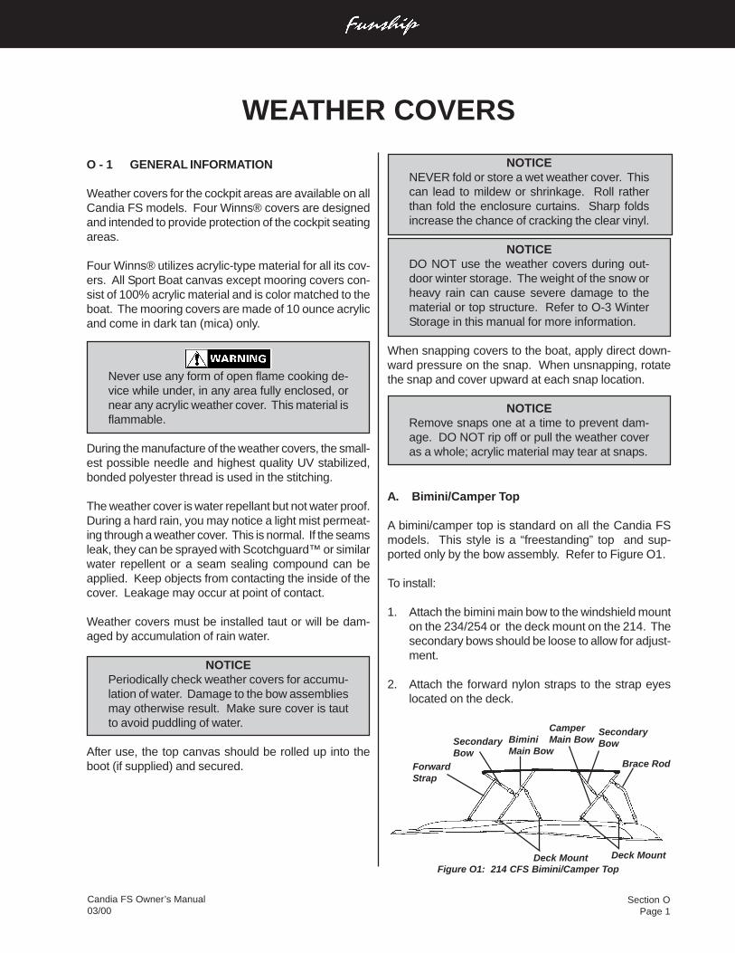
Section OPage 1
Candia FS Owner’s Manual03/00
NOTICENEVER fold or store a wet weather cover. Thiscan lead to mildew or shrinkage. Roll ratherthan fold the enclosure curtains. Sharp foldsincrease the chance of cracking the clear vinyl.
NOTICEDO NOT use the weather covers during out-door winter storage. The weight of the snow orheavy rain can cause severe damage to thematerial or top structure. Refer to O-3 WinterStorage in this manual for more information.
When snapping covers to the boat, apply direct down-ward pressure on the snap. When unsnapping, rotatethe snap and cover upward at each snap location.
NOTICERemove snaps one at a time to prevent dam-age. DO NOT rip off or pull the weather coveras a whole; acrylic material may tear at snaps.
A. Bimini/Camper Top
A bimini/camper top is standard on all the Candia FSmodels. This style is a “freestanding” top and sup-ported only by the bow assembly. Refer to Figure O1.
To install:
1. Attach the bimini main bow to the windshield mounton the 234/254 or the deck mount on the 214. Thesecondary bows should be loose to allow for adjust-ment.
2. Attach the forward nylon straps to the strap eyeslocated on the deck.
Figure O1: 214 CFS Bimini/Camper Top
WEATHER COVERS
O - 1 GENERAL INFORMATION
Weather covers for the cockpit areas are available on allCandia FS models. Four Winns® covers are designedand intended to provide protection of the cockpit seatingareas.
Four Winns® utilizes acrylic-type material for all its cov-ers. All Sport Boat canvas except mooring covers con-sist of 100% acrylic material and is color matched to theboat. The mooring covers are made of 10 ounce acrylicand come in dark tan (mica) only.
Never use any form of open flame cooking de-vice while under, in any area fully enclosed, ornear any acrylic weather cover. This material isflammable.
During the manufacture of the weather covers, the small-est possible needle and highest quality UV stabilized,bonded polyester thread is used in the stitching.
The weather cover is water repellant but not water proof.During a hard rain, you may notice a light mist permeat-ing through a weather cover. This is normal. If the seamsleak, they can be sprayed with Scotchguard™ or similarwater repellent or a seam sealing compound can beapplied. Keep objects from contacting the inside of thecover. Leakage may occur at point of contact.
Weather covers must be installed taut or will be dam-aged by accumulation of rain water.
NOTICEPeriodically check weather covers for accumu-lation of water. Damage to the bow assembliesmay otherwise result. Make sure cover is tautto avoid puddling of water.
After use, the top canvas should be rolled up into theboot (if supplied) and secured. Brace Rod
Deck Mount
SecondaryBowSecondary
BowBiminiMain Bow
Deck Mount
CamperMain Bow
ForwardStrap
Section OPage 2
Candia FS Owner’s Manual03/00
3. Snap the cockpit cover sides and rear (if applicable)to the deck.
An adjustable pole is provided to adjust the canvas fortautness.
D. Mooring Cover
Mooring covers, available for all the Candia FS mod-els, are intended for longer term storage and spreadover the entire boat. If used in areas with snow accumu-lation, be sure to support the canvas adequately andinspect frequently for snow loads or damage will occur.Refer to O-3 Winter Storage for additional information.
To install:
1. Spread mooring cover over entire boat.
2. Install adjustable poles in bow area (if applicable)and in the rear cockpit. Be sure the canvas is tautand no pockets exist.
3. Tie off at the transom.
4. Nylon loops are provided for attaching rope or bungiecords to the trailer or from side to side (under theboat).
O - 2 TRAILERING
High winds encountered during trailering your boat canseverely damage most weather covers. If an extendedtrip at highway speeds is planned, the top and otherweather covers should be in the down position or re-moved entirely. This will prevent damage and loss.
NOTICEDO NOT tow your boat at highway speeds withweather covers in place. High winds encoun-tered during trailering your boat can severelydamage most weather covers. Damage toweather covers incurred as a result of traileringyour boat is not covered under warranty.
3. Attach the camper main bow to the deck mount.
4. Attach the brace rod to the angled stern deck mount.
5. Adjust the secondary bows and straps for tautness.
You may choose to run your Candia FS with the biminitop either fully deployed or folded together (closed) andsecured with the boots provided. Either way it is de-signed to remain mounted. No storage is provided forthis top in your boat.
NOTICEIf you desire to remove the bimini top (winterstorage), use two people. This will help mini-mize the risk of injury and help prevent dam-age to the upholstery, the bimini top, and/or theboat.
NOTICEThe bimini/camper is a single unit. It can notbe used with any other piece of canvas.
B. Forward Cover
The forward cover is available on 234 and 254 CandiaFS models. It is installed over the bow seating area andis snapped to the deck and to the cockpit cover at thewalk-through. An adjustable pole is provided to adjustthe canvas for tautness. Refer to Figure O1.
C. Cockpit Cover
The cockpit cover is used to cover the complete cockpitarea and is intended as a short term storage cover. Thecockpit cover is only available for the 234 and 254Candia FS.
To install:
1. Snap the forward edge of the cockpit cover to thewalk-through on the windshield. Windshield snapswill slide to adjust to the canvas.
2. Secure the rear corners.
a. If the canvas has snaps along the aft edge, se-cure the corners.
b. If the canvas has shock cords along the aft edge,attach to knobs as shown in Figure O2.
Section OPage 3
Candia FS Owner’s Manual03/00
Clear vinyl curtains and windows demand extra care toprevent scratching. DO NOT use cloth or chamois skin.Dirt or grit in the cloth will scratch the vinyl window. Hoseclean water onto vinyl to rinse off salt, dirt, or grime.
NOTICEDO NOT use hot water. DO NOT dry in an auto-matic dryer. DO NOT dry clean or steam press.
Leakage after cleaning may be the result of insufficientrinsing. Re-rinse. If leakage continues, apply a coat ofsilicone air drying water repellent, such asScotchguard™. See your Four Winns® dealer foradditional information on weather covers.
O - 5 CARBON MONOXIDE
When the boat is underway, a natural vacuum may existwith the right wind and sea conditions to draw the ex-haust gases (which includes carbon monoxide) into theboat. When the side curtains are installed, this com-pounds the possibility of this occurring. Carbon monox-ide may also be present when mooring or near sea walls.For more information, refer to Section B-2 Carbon Mon-oxide in this manual.
The carbon monoxide in exhaust fumes can be hazard-ous. It is important for you and your passengers to beaware of the potential safety hazard created by exhaustfumes. Familiarize yourself with the symptoms of indi-viduals overcome by carbon monoxide, and most im-portantly, ways you can protect yourself and your guests.
Exhaust fumes from engines contain carbonmonoxide. Boats with canvas deployed aremore likely to collect exhaust fumes. Avoidbrain damage or death from carbon monox-ide. Keep cockpit and cabin areas well venti-lated. Signs of exposure include nausea, diz-ziness, and drowsiness. See Section B-2 ofthe boat owner’s manual for more details. Ifusing a catalytic heater, provide ventilation. Donot use catalytic heater while sleeping.
O - 3 WINTER STORAGE
The boat must be properly protected during winter drydock storage. A winter storage cover is advisable. Manymarine dealers offer shrinkwrap enclosures for outdoorstorage. See a Four Winns® dealer for information onthe availability of winter storage covers or other alterna-tives for storage.
When storing outdoors, make sure the supporting frame-work keeps the weight of the snow and rain from accu-mulating on the storage cover. Proper ventilation mustalso be provided or dry rot and mildew will occur. SeeSection R General Maintenance for additional winter stor-age information.
O - 4 MAINTENANCE
Moisture, dirt, chemicals from industrial fallout, heat, ul-traviolet rays and in some cases, salt water are factorswhich affect the longevity of acrylic covers.
1. Moisture can cause shrinkage and mildew. Allowthe cover to dry thoroughly before disassemblingtops. Keep it clean and well ventilated to preventmildew. Spraying the weather cover with LysolDisinfectant™ or similar product will help preventmildew.
2. Dirt creates a starting point for mildew when mois-ture is present. Clean the top with a sponge or softscrub brush and mild detergent when the cover isinstalled. Make sure cover is taut to help preventshrinkage.
3. Chemicals cause decay if allowed to accumulate forlong periods of time. Keep the cover clean to pre-vent decay.
4. Heat can cause cracks in vinyl components and stiff-ening of fabric when enclosed in plastic or polyeth-ylene. DO NOT store the weather cover in polyeth-ylene under direct sunlight or high temperature situ-ations.
5. Ultraviolet degradation may occur under prolongedexposure to direct sunlight. Store the top in the bootwhen not in use.
6. Salt water can corrode brass, aluminum, or stain-less steel fittings and fasteners. Keep fittings clean,lubricated, and waxed to prevent corrosion.
Section PPage 1
Candia FS Owner’s Manual03/00
Fiberglass cockpit liners and seat base are constructedsimilar to the hull. Balsa core or coremat laminationsare utilized when necessary.
In addition to a thorough visual inspection of each fiber-glass component, samples are measured using specialequipment, for fiberglass reinforcement to resin ratio,laminate configuration, weight and thickness. By theseprocedures Four Winns® ensures proper composition.
P - 3 EQUIPMENT INSTALLATION
Many boats are used for specific purposes or under con-ditions which require the addition of special equipmentto the hull or deck. Special care must be taken duringthe installation of any equipment to a fiberglass com-ponent. A polysulfide or butyl based sealant should beused to seal installations below the water line. Silicone“marine” seal or similar bedding compound should beused elsewhere.
NOTICEDO NOT install any item onto or through thehull without adequately sealing the hull areapenetrated by the installed item or related fas-teners. Improper installations could cause leak-age or allow water absorption and thus causeserious hull damage.
Always predrill fastening holes with a proper sizebit. Predrilling will help prevent the fiberglassfrom splintering and thus causing unsightly dam-age. Also, countersink holes to prevent the gelcoat from chipping.
Any equipment which will be subjected to cyclic loadingor significant force should be through- bolted to a fiber-glass component. A butt block or backing plate shouldbe used to strengthen any area onto which an item willbe mounted.
P - 1 HULL DESIGN INFORMATION
Four Winns® boats are designed using the sound engi-neering and mathematical principles of hydrostatics,hydrodynamics, structure, and strength of materials. Thematerials utilized provide optimum strength at the light-est possible weight. The exact fiberglass laminate sched-ule and construction techniques of each part is deter-mined in accordance with the strength and rigidity re-quired.
All Four Winns® include our patented Stable-Vee™ hulldesign. Pods on either side of the outdrive extend therunning surface beyond the transom. These pods, plusthe unique distribution of deadrise from transom to bow,allows Four Winns® to place more hull in the water thandeep-vee designs of similar length and beam. This re-sults in better boat handling whether on plane, duringturns, or at rest.
P - 2 FIBERGLASS CONSTRUCTION
The fiberglass components of Four Winns® boats areof the finest quality materials, workmanship and con-struction techniques available. This ensures the struc-tural integrity to provide years of boating enjoyment withminimal maintenance.
The construction of a Four Winns® hull begins with theapplication of gel coat to the mold. The gel coat is ap-proximately 25 mils thick. A coat of resin and choppedfiberglass is then sprayed into the hull and carefully handrolled until it is securely affixed to the gel coat.
A number of fiberglass layers and woven roving are ap-plied to the above laminate. Each layer is hand laid andhand rolled. The keel and chine areas have fiberglasswoven roving overlapped in these areas to provide addi-tional strength. Some models utilize encapsulatedend-grain balsa core or coremat laminates to achieveadditional rigidity. Others utilize additional laminations ofwoven roving to maintain strength and rigidity.
The hull support stringers are located using special tools,and are fiberglassed into place. This ensures a strong,rigid hull, permanently formed into a solid assembly, freeof distortions.
FIBERGLASS AND HULL INFORMATION
Section PPage 2
Candia FS Owner’s Manual03/00
When cleaning nonskid areas, DO NOT attempt to usea wire brush or sandpaper because this will remove thenonskid gel.
Apply wax once a month to maintain gel coat lustre. Readthe label before using any product. Make sure productis applicable to fiberglass. Refer to the brochure on gelcoat care in your owner’s packet. Also, consult a FourWinns® dealer for his recommendations.
NOTICEDo not use carnuba based waxes. This typeof wax yellows over time and makes the fiber-glass appear yellow.
Waxing decks, cockpit floors or other areas onwhich one walks is not recommended. Waxingwill produce a very slippery surface, especiallywhen wet. Wax may also buildup in the non-skid surfaces. Be sure all persons wear deckshoes while aboard the boat. Footing will beimproved and feet will be protected from acci-dental cuts and bruises.
A darkening or discoloration of the nonskid surfaces cansometimes occur as a result of wax buildup. Exposureto the sun and elements can turn the wax darker, or oc-casionally can cause it to become flaky or powdery. Toremove, use fine rubbing compound and a low RPMbuffer (1200 to 2000 RPM). Apply light pressure andkeep the buffer moving at all times to prevent heat buildup. Read the directions before using any equipment.
B. Weathering Effects on Gel Coat
Weathering occurs from direct sunlight, water, chemi-cals, and dust. Some of the terms below describe thechanges that can occur to the gel coat surface.
Chalking is a result of the gel coat’s top surface beingbroken down into an extremely fine powder. When thishappens, the color whitens. The chalk is present on thesurface only.
Fading is the uniform change in color. This happenswhen the actual pigments have changed color, espe-cially from excessive chalking, or when the gel coat haseither been stained or bleached by something.
P - 4 FIBERGLASS CARE & MAINTENANCE
Fiberglass is affected by weathering processes and re-quires maintenance on a periodic basis to help maintainthe beauty and shine. The effects upon the gel coat willbe dependent upon boating conditions, storage, type ofuse, and the care given to the boat during the boatingseason.
Four Winns® utilizes fade-fighting ArmorcoatTM gel coatin the exterior finish. It is specially formulated to resistfading and yellowing, and retain more of its original glossthan better grade gel coats. However, it is still importantto maintain the gel coat to protect the finish.
A. General Maintenance
For fresh water use, the boat should be washed once ortwice a month. When using in a salt water environment,considerable more care will be necessary. Be carefulwhen selecting a cleaning agent. Hand dishwashingdetergents are usually gentle and are recommended forcleaning gel coat. Cleaning products such as Ivory orDawn hand dishwashing liquid can be safely used. Al-ways read the label before using any product.
NOTICEDO NOT use acetone, paint thinner, solvents,or strong alkaline based detergents, nor clea-ners with a “gritty” and abrasive texture. Avoidproducts which contain sodium phosphate.Common examples of these types of householdcleaning agents are: Tide™, Oxydol™, Janit-or-in-a-Drum™, Fantastik™, Clorox™, etc. Al-ways read the label before using an agent.
There are several products available which are specifi-cally designed to clean fiberglass exterior finishes. Manycompanies like Johnson & Johnson®, Turtle Wax®, etc.manufacture cleaning fluids mild enough to clean with-out stripping the wax.
NOTICETreading on a soiled fiberglass surface can se-verely scratch and mar the finish. Keep the fi-berglass as clean as possible.
Section PPage 3
Candia FS Owner’s Manual03/00
NOTICEWhen sanding, DO NOT use a power or beltsander to prevent gouges, uneven areas, orother damage. For best results, block sand thegel coat.
C. Stains
Stains can appear anywhere on the exterior of the boatand may be a result of contact with tar, plant sap, leaves,rust from metal fittings, and other materials. Surfacestains may be removed with hand dishwashing soap,mild cleansers, or some household detergents. DO NOTuse chlorine or ammonia products. These products canaffect the color of gel coat. Commercial car washes usestrong cleaners and should be avoided.
To remove stains, refer to the procedures below.
1. Wash area with hand dishwashing soap.
2. Begin with a small area such as three feet by threefeet and apply a mild cleanser.
3. Rinse with clean water.
4. Follow with compound and waxing as outlined inprocedure above.
If the stain is not removed by the hand dishwashing soapor mild cleanser, then the next procedure is to use eitherdenatured or rubbing alcohol. If this does not work, con-sult your Four Winns® dealer for professional assistance.
NOTICEDO NOT use acetone, ketone, or other solventsto remove stains. These chemicals are flam-mable and may damage the gel coat.
P - 5 FIBERGLASS REPAIRS
Fiberglass is one of the most durable, strong, and for-giving construction materials afloat. It is resilient andnormal repairs can be made without affecting the strengthor structural integrity of the boat.
Yellowing is gel coat which has a yellow cast and strea-king usually deals with a stain or contact with anothersurface.
Gloss refers to the shine of the surface. This can changefrom sanding action, chalk, residues, or exposure.
Blistering refers to a condition in which the unprotectedgel coat surface below the waterline has absorbed wa-ter and formed bubbles. See Section P-5 for additionalinformation.
Follow the instructions below for boats that have weath-ered and chalked.
1. Wash.
2. Wax. If this does not work, then use a fine rubbingcompound. If this does not work use 400 or 600 wetor dry sandpaper, followed by fine rubbing compoundand wax.
When using wax or fine rubbing compounds, make sureto read the label and follow the directions. Some helpfultips are listed below.
1. Avoid working in direct sunlight. This dries out thewax or compound, and can stain the surface.
2. Use clean pads or cloths to apply a thin coating ofwax or rubbing compound to a small area such asthree feet by three feet. Remove any excess, andthen rub the area with a buffing pad, or power buffer.Apply pressure only as necessary to restore the sur-face finish. Applying too much pressure or buffingin one place too long can permanently damage thesurface.
3. After applying compound, always follow with wax-ing.
NOTICEIf using a power buffer, use a low RPM bufferwith light pressure. Keep the pad wet and thebuffer moving at all times to prevent heat buildup.
Section PPage 4
Candia FS Owner’s Manual03/00
Striking docks, other boats, or submerged ob-jects could create a very hazardous situation orseverely damage the fiberglass. In the event anobject is struck below or near the waterline, pro-ceed directly and cautiously to the nearest ser-vice facility and remove the boat from the water.Closely inspect the hull for damage. If the outerfiberglass laminate was penetrated, repairs mustbe made prior to relaunch.
Occasionally, blisters, crazing, scratches, or damage tothe fiberglass can occur. Repairs may be necessary tocorrect the problem.
A. Scratches
Scratches occur during normal use. Below is a step bystep procedure to repair scratches.
1. Clean area with soap and water.
2. Apply a fine rubbing compound and buff.
3. Wax.
If this does not work, clean the area and sand lightly with400 to 600 wet or dry sandpaper and follow with rubbingcompound and wax.
B. Gouges & Cracks
Stress cracks and crazing are the appearance of hairlinecracks in the gel coat surface. When present, these prob-lems usually occur in the gel coat finish or the outer “skincoat” fiberglass laminate. The appearance of thesecracks does not pose a threat to the structural integrity ofthe boat. In most cases, they are cosmetic and can betreated.
Cosmetic surface damage can be repaired as follows:
1. Sand the surrounding area with medium or fine gritsandpaper. Clean all marine growth, dirt, antifoulingpaint, etc. from the immediate area. DO NOT ex-cessively scratch or gouge the surrounding area.
2. Use a hard, pointed tool to open the gel crack. Takecare not to damage the surrounding gel coat.
3. Sand the crack or gouge so the edges are smoothand will allow proper “feathering” of the area.
4. Clean the area thoroughly. Make sure the area isdry before proceeding.
NOTICEBe sure the structure and the ambient tempera-ture are above 60 degrees F (15 degrees C)and the relative humidity below 70% immedi-ately before, during, and after the repair.
5. If the nick or gouge is deep and penetrates throughthe gel coat, fill the area with fiberglass patchingpaste. Follow the directions on the can when mix-ing the paste with the catalyst.
6. After the gouge is filled and has dried, sand thepatched area. Begin by using medium-fine gradesandpaper. Progressively use finer grade sandpa-per until the surface is very smooth. If necessary,add filler and then sand the surface again.
7. Apply two or three light coats of matching fiberglassgel coat to the repaired area. Enough gel coatshould be used so that the entire area is covered.
The gel coat must be catalyzed using up to 2% MEKPeroxide which can be purchased at a supplier han-dling fiberglass reinforced products. Contact yourFour Winns® dealer for assistance.
8. After ample drying time, sand the area using veryfine wet/dry sandpaper. If the appearance of thearea is still not satisfactory, repeat steps 2 through8 as necessary.
9. If above the waterline, polish the area using a fiber-glass rubbing compound and then wax. If the re-paired area is below the waterline, the area shouldbe primed and painted in accordance with the anti-fouling paint manufacturer’s instructions.
Gel coat, like paint, will change colors with time andexposure to sunlight (ultraviolet). For this reason,“matching” gel coat obtained from Four Winns® maynot match the gel color of a boat that has been exposed.However, this is the closest match commercially avail-able. A fiberglass technician can tint the gel to be usedin the repair to provide a closer color match.
Section PPage 5
Candia FS Owner’s Manual03/00
Antifouling paint begins reaction upon contact with wa-ter. After a season’s use or sooner under certain condi-tions, the antifouling paint may appear to be dissolving.This is due to the paint’s chemical emission that in turnretards marine growth. When this occurs, refinishing isin order.
Four Winns® recommends reapplication of the antifoul-ing paint seasonally. The effectiveness of the paint willbe drastically reduced if used longer. ThoughFour Winns® has found the antifouling paints used toprovide good marine growth protection in most water,other paints may be more effective in certain water con-ditions. See a Four Winns® dealer for recommenda-tions on antifouling paint use in your area.
NOTICEDuring surface preparation, the hull should besanded only enough to remove any foreign mat-ter, and loose paint. DO NOT sand deeply intothe gel coat, fiberglass cosmetic problems couldlater result. After sanding, the surface shouldbe wiped with a rag treated with a cleaner recom-mended by the antifouling paint manufacturer.The surface must be clean and slightly rough toensure paint adhesion.
Prior to application of the antifouling paint, the boat ownermay consider coating the hull bottom with an epoxy coat-ing. Four Winns® recommends this procedure as a pre-ventive and effective means of controlling osmotic blis-tering. Most major antifouling paint manufacturers alsosupply a line of epoxy undercoatings. Consult your FourWinns® dealer for recommendations on epoxy under-coatings.
P - 7 HULL SUPPORT
Proper support of the hull while it is out of the water isimperative. Due to the design complexities, Four Winns®does not recommend trailers or storage cradles be home-made. The boat is a valuable piece of equipment. DONOT risk permanent damage to the hull structure in anattempt to save the cost of an adequate support. Improp-er support can lead to serious and permanent hull defor-mation.
Failure to adequately support the hull mayresult in permanent hull structure damageand will invalidate the hull structure war-ranty.
More severe fiberglass damage, especially when struc-tural, requires the expertise of an experienced fiberglassrepair technician. See your Four Winns® dealer for as-sistance.
NOTICEImproper repair techniques can lead to furtherfiberglass component damage.
C. Osmotic Blistering
Osmotic blistering or “boat pox” is an unfortunate butnot uncommon occurrence in fiberglass boats. Fiber-glass is water retardant, not waterproof. When a boat isleft in the water for a period of time, the fiberglass willabsorb water. It is a natural process that can not beeliminated in production methods or material selectionand usage. However, there are ways to control andpossibly prevent blisters (see Section P-6). If you doencounter blisters, be assured that the blisters are merelycosmetic. They do not indicate a defect in the boat struc-ture or lamination. Four Winns®, along with most boatmanufacturers, regard gel blisters as a standard main-tenance item.
The repair procedure for gel coat blisters is similar tothe procedures outlined in the previous section on cracksand gouges. There is an exception however, in that thehull must dry out for several days or possibly weeksbefore repairs can proceed.
To determine if the hull has dried sufficiently, tape onesquare foot of household plastic wrap securely to thehull bottom. Make sure all edges are sealed and let itstand for twenty-four hours. If condensation has accu-mulated under the plastic, the hull is still “wet” and mustbe allowed to dry longer before repairing.
When the repair is completed, an application of an ep-oxy barrier coat should be considered. This will helpprevent the possibility of reoccurrence of blisters. YourFour Winns® dealer or local ship store will have informa-tion on barrier coat products.
P - 6 ANTIFOULING PAINT
Four Winns® recommends antifouling or bottom paintfor boats which will be kept in the water for extendedperiods of time. Antifouling paint reacts with water toretard the growth of algae, barnacles and other marinegrowth on the hull. In addition to marine growth, it offersprotection against excessive water pollution.
Section PPage 6
Candia FS Owner’s Manual03/00
NOTICEWhen attempting to raise the hull, never allowone end of the boat to rise first, while letting theopposite rest momentarily on the outdrives orunderwater gear. Serious damage to these com-ponents could result. DO NOT place liftingstraps on underwater gear. Be sure the strap isagainst the hull surface only.
A trailer, or storage cradle designed for a larger or smallerboat will not provide proper support for the hull. Thiscould lead to hull deformation and thus serious perfor-mance deficiencies.
Four Winns® trailers are available for all Candia FS mod-els. Refer to Section S - Trailers for additional informa-tion.
Section QPage 1
Candia FS Owner’s Manual03/00
Q - 1 HIGH-PRESSURE LAMINATE CARE
Table tops consist of a high pressure laminate, “formica”like material. The formica has a “matte texture” finishand can be cleaned with hand dishwashing soap andwater or other cleaning solutions such as Fantastik™.Always read the label before using any product.
NOTICEDO NOT use abrasive cleaners or solvents onformica. DO NOT use Soft Scrub™ soap orsimilar cleaning products; they will scratch thesurface and remove the shine.
Q - 2 STAR BOARD
Star board is a high density polyethylene (plastic) and isvery durable and fade resistant. Star board requires littlemaintenance, and is being used in place of wood in manyareas of the boat. It is currently being used for ski rackfacers, ski locker lids, and seat supports.
To clean star board, use a solvent-free, nonabrasivecleaner such as hand dishwashing soap or Fantastik™.Read the label before using any cleaning product.
NOTICEStar board will stain when exposed to certainoils or chemicals. Always wipe up any spillsimmediately.
Q - 3 CHERRY ENHANCEMENTS
Cherry enhancements are standard on Candia FS mod-els. They consist of a finished synthetic cherry. Thischerry is found in the instrument panel of the 214 CFS(I/O and O/B). The 234/254 Funships also have a cherrytrim ring framing the VDO instrument module. In addi-tion, the ignition switch panels and the emergencyswitch panels, consist of this cherry.
To clean, a damp cloth will usually suffice.
WOODWORK AND COMPOSITES
Section RPage 1
Candia FS Owner’s Manual03/00
R - 1 WINTERIZATION
A. Prior to Lifting for Winter Layup
1. Pump out the head (dockside discharge if appli-cable), and be sure the holding tank is empty. Flushthe head holding tank with soap, water and a de-odorizer (e.g., Lysol Liquid™). Add more water ifnecessary. Have the cleaning solution pumped out.
2. Have the fuel tank either full or completely empty.See the Engine Owner's manual for recom-mendations. Also, check with the dry dock opera-tors for recommendations. If winter storing with afull fuel tank, gasoline winterizer such as Sta-bil®Fuel Conditioner will reduce varnishing, condensa-tion, etc.
NOTICEIf the fuel has been treated with winterizer, runengines for ten minutes to make sure the treatedfuel is present in all lines and parts of the en-gine.
3. Drain water from the fresh water system (if appli-cable).
4. Winterize the engine and drive systems as recom-mended in the Engine Owner's manual. Portions ofthis winterization procedure may require that the boatbe lifted.
5. If the boat is to be lifted or taken off the trailer, seeSection P-7 Hull Support in this manual for addi-tional details.
B. After Lifting
1. Remove the drain plug.
2. Thoroughly wash the fiberglass exterior, especiallythe hull bottom. Remove as much marine growthas possible.
3. Lower boat onto cradle properly or place boat ontrailer. Be sure boat is adequately supported. Theboat should be raised slightly under the forward sup-ports or trailer tongue to improve drainage to thetransom drain.
4. Be sure all the water is completely drained from thefresh water system. Disconnect all hoses, checkvalves, etc. and blow all the water from the systemusing very low air pressure. The use of nontoxic,fresh water system antifreeze is recommended asan alternative to disassembling the water system.Refer to Section J-5 System Maintenance in thismanual for information on winterizing the water sys-tem.
5. Winterize the head as recommended by the headmanufacturer. If the boat is equipped with a holdingtank, mix some antifreeze solution and pour it intothe head. Transfer some of the antifreeze to theholding tank by flushing the head. Also, refer toSection J-5 System Maintenance for additionalinformation.
6. Ensure that all water is removed from the bilge pumpand bilge pump lines. Dry the hull bilge, andself-bailing cockpit drain troughs. Water freezing inthese areas could cause damage. See Section K-2Hull Drainage Systems.
7. Remove the battery(s) and store in a cool place.Clean the batteries using clear, clean water. Be surethe battery has sufficient water and clean terminals.Keep the battery(s) charged throughout the storageperiod. DO NOT store the battery(s) on a concretefloor or other damp or conductive surface.
8. Remove the butane canister from the stove (ifapplicable) and store in a cool, dry place away fromheat or spark.
9. Clean the boat interior thoroughly. Vacuum carpets,and dry clean drapes and upholstery jackets as nec-essary.
10. Scrub the hull bottom and wash exterior fiberglasscomponents, wax lightly.
11. Clean exterior upholstery with mild soap and water.Rinse and dry thoroughly.
12. Remove all oxidation from exterior hardware andapply a light film of moisture - displacing lubricant.
GENERAL MAINTENANCE
Candia FS Owner’s Manual03/00
Section RPage 2
C. Prior to Winter Storage
1. Remove as many cushions as possible. Removestorage lids or hatches. Open as many locker doors,as possible. Leave these areas open to improveventilation.
2. Spray the weather covers and the boat upholsterywith Lysol Spray Disinfectant™. Enclosed areassuch as storage locker areas should also be sprayedwith Lysol Disinfectant™.
3. Place small dishes of rodent poison such as D-Con™in a number of areas around the boat. Be sure dishesare placed near the head and the engines, as ro-dents will destroy upholstery, water intake and dis-charge hoses.
4. If the boat will be in outside storage, properly sup-port a storage cover and secure it over the boat.DO NOT secure the cover tightly to the boat. Thisdoes not allow adequate ventilation and can lead todry rot. DO NOT store the boat in a damp storageenclosure. Excessive dampness can cause electri-cal problems, corrosion, and dry rot.
5. DO NOT use the bimini top or camper top as a win-ter storage cover. The life of these covers may besignificantly shortened if exposed to harsh weatherelements for long periods.
Placing an electric or fuel burning heating unitin the bilge of the boat during cold weather couldcause fire or explosion and is not recommended.
NOTICEBoats stored outside in areas with heavy snowaccumulation are more susceptible to damage,and should be inspected regularly during the win-ter months
6. Engine should be winterized according tothe engine manufacturers manual.
R - 2 ENGINE FLUSH OUT
The optional engine flush out should be used to cleanthe engine of unwanted salt, mud, sludge, etc. whichmay have accumulated in the engine cooling system.Before winterizing the engine, flush out the system for atleast five minutes.
Make sure that no section of flush hoses are incontact with moving or hot engine parts or abra-sive surfaces such as screw threads, sharpedges, etc., which could damage the hoses.Damage to the hoses could cause leaks andpossible flooding of the engine compartment.Periodically check hoses for abrasions.
NOTICEThe flush out kit should only be used with theboat in the water and the engine OFF.
To flush out the engine, follow the instructions below.
1. Do not run engine during flushing procedure.
2. Remove cap from coupling and attach swivel con-nector.
3. Attach water supply hose to swivel connector.
4. Turn water on and allow water to flush the engineand exhaust manifold for five to ten minutes.
5. Turn water off. Disconnect hose; replace and tightencap securely.
Reinstall cap onto coupler after flushing. Floo-ding of the engine compartment will occur if thecap is not installed and tightened.
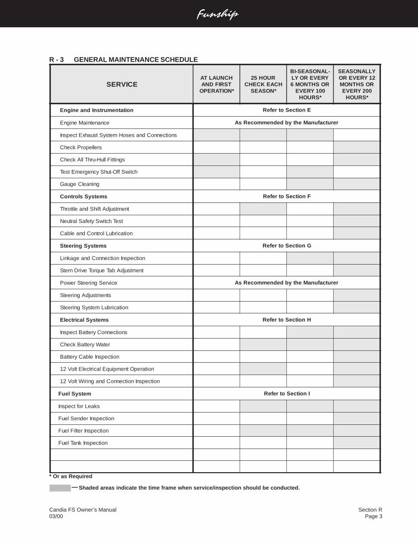
Section RPage 3
Candia FS Owner’s Manual03/00
R - 3 GENERAL MAINTENANCE SCHEDULE
* Or as Required
Shaded areas indicate the time frame when service/inspection should be conducted.
ECIVRESHCNUALTATSRIFDNA
*NOITAREPO
RUOH52HCAEKCEHC
*NOSAES
-LANOSAES-IBYREVEROYLROSHTNOM6
001YREVE*SRUOH
YLLANOSAES21YREVERO
ROSHTNOM002YREVE
*SRUOH
noitatnemurtsnIdnaenignE EnoitceSotrefeR
ecnanetniaMenignE rerutcafunaMehtybdednemmoceRsA
snoitcennoCdnasesoHmetsyStsuahxEtcepsnI
srelleporPkcehC
sgnittiFlluH-urhTllAkcehC
hctiwSffO-tuhSycnegremEtseT
gninaelCeguaG
smetsySslortnoC FnoitceSotrefeR
tnemtsujdAtfihSdnaelttorhT
tseThctiwSytefaSlartueN
noitacirbuLlortnoCdnaelbaC
smetsySgnireetS GnoitceSotrefeR
noitcepsnInoitcennoCdnaegakniL
tnemtsujdAbaTeuqroTevirDnretS
ecivreSgnireetSrewoP rerutcafunaMehtybdednemmoceRsA
stnemtsujdAgnireetS
noitacirbuLmetsySgnireetS
smetsySlacirtcelE HnoitceSotrefeR
snoitcennoCyrettaBtcepsnI
retaWyrettaBkcehC
noitcepsnIelbaCyrettaB
noitarepOtnempiuqElacirtcelEtloV21
noitcepsnInoitcennoCdnagniriWtloV21
metsySleuF InoitceSotrefeR
skaeLroftcepsnI
noitcepsnIredneSleuF
noitcepsnIretliFleuF
noitcepsnIknaTleuF
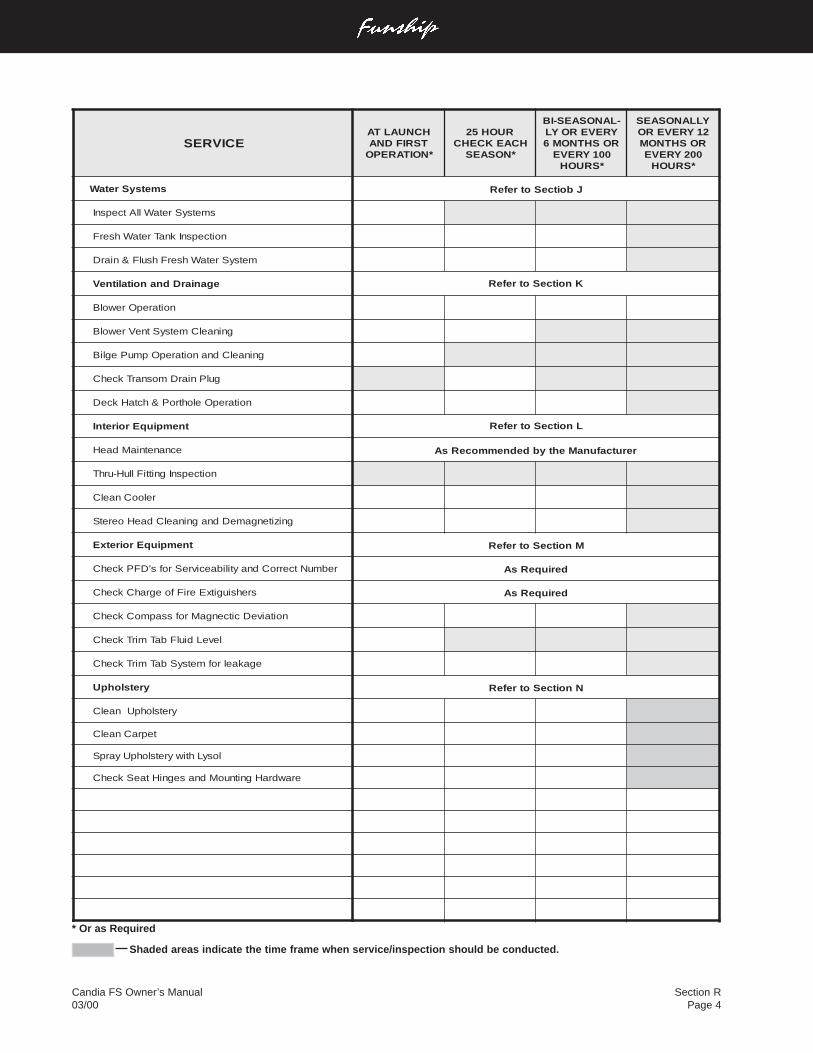
Candia FS Owner’s Manual03/00
Section RPage 4
* Or as Required
Shaded areas indicate the time frame when service/inspection should be conducted.
ECIVRESHCNUALTATSRIFDNA
*NOITAREPO
RUOH52HCAEKCEHC
*NOSAES
-LANOSAES-IBYREVEROYLROSHTNOM6
001YREVE*SRUOH
YLLANOSAES21YREVERO
ROSHTNOM002YREVE
*SRUOH
smetsySretaW JboitceSotrefeR
smetsySretaWllAtcepsnI
noitcepsnIknaTretaWhserF
metsySretaWhserFhsulF&niarD
eganiarDdnanoitalitneV KnoitceSotrefeR
noitarepOrewolB
gninaelCmetsyStneVrewolB
gninaelCdnanoitarepOpmuPegliB
gulPniarDmosnarTkcehC
noitarepOelohtroP&hctaHkceD
tnempiuqEroiretnI LnoitceSotrefeR
ecnanetniaMdaeH rerutcafunaMehtybdednemmoceRsA
noitcepsnIgnittiFlluH-urhT
relooCnaelC
gnizitengameDdnagninaelCdaeHoeretS
tnempiuqEroiretxE MnoitceSotrefeR
rebmuNtcerroCdnaytilibaecivreSrofs'DFPkcehC deriuqeRsA
srehsiugitxEeriFfoegrahCkcehC deriuqeRsA
noitaiveDcitcengaMrofssapmoCkcehC
leveLdiulFbaTmirTkcehC
egakaelrofmetsySbaTmirTkcehC
yretslohpU NnoitceSotrefeR
yretslohpUnaelC
tepraCnaelC
losyLhtiwyretslohpUyarpS
erawdraHgnitnuoMdnasegniHtaeSkcehC
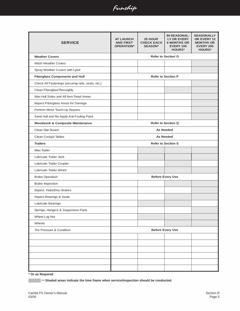
Section RPage 5
Candia FS Owner’s Manual03/00
* Or as Required
Shaded areas indicate the time frame when service/inspection should be conducted.
ECIVRESHCNUALTATSRIFDNA
*NOITAREPO
RUOH52HCAEKCEHC
*NOSAES
-LANOSAES-IBYREVEROYLROSHTNOM6
001YREVE*SRUOH
YLLANOSAES21YREVERO
ROSHTNOM002YREVE
*SRUOH
srevoCrehtaeW OnoitceSotrefeR
srevoCrehtaeWhsaW
losyLhtiwsrevoCrehtaeWyarpS
lluHdnastnenopmoCssalgrebiF PnoitceSotrefeR
).cte,staes,sliargniruces(sgninetsaFllAkcehC
ylhguorohTssalgrebiFnaelC
saerAdaerT-noNllAdnasediSlluHxaW
egamaDrofsaerAssalgrebiFtcepsnI
sriapeRpU-hcuoTroniMmrofreP
tniaPgniluoF-itnAylppA-eRdnalluHdnaS
ecnanetniaMetisopmoC&krowdooW QnoitceSotrefeR
draoBratSnaelC dedeeNsA
selbaTtipkcoCnaelC dedeeNsA
sreliarT SnoitceSotrefeR
reliarTxaW
kcaJreliarTetacirbuL
relpuoCreliarTetacirbuL
hcniWreliarTetacirbuL
noitarepOekarB esUyrevEerofeB
noitcepsnIekarB
sekarBcsiD/sbuHtcepsnI
slaeS&sgniraeBtcepsnI
sgniraeBetacirbuL
straPnoisnepsuS&sregnaH,sgnirpS
tuNguLleehW
sleehW
noitidnoC&erusserPeriT esUyrevEerofeB
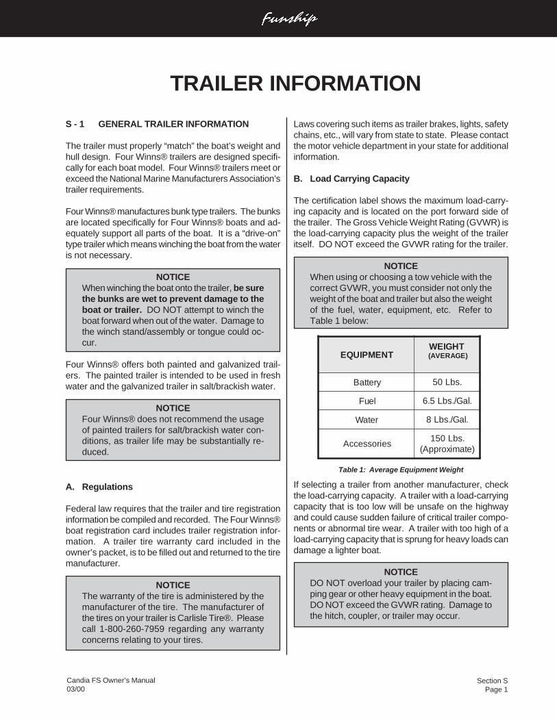
Section SPage 1
Candia FS Owner’s Manual03/00
Laws covering such items as trailer brakes, lights, safetychains, etc., will vary from state to state. Please contactthe motor vehicle department in your state for additionalinformation.
B. Load Carrying Capacity
The certification label shows the maximum load-carry-ing capacity and is located on the port forward side ofthe trailer. The Gross Vehicle Weight Rating (GVWR) isthe load-carrying capacity plus the weight of the traileritself. DO NOT exceed the GVWR rating for the trailer.
NOTICEWhen using or choosing a tow vehicle with thecorrect GVWR, you must consider not only theweight of the boat and trailer but also the weightof the fuel, water, equipment, etc. Refer toTable 1 below:
If selecting a trailer from another manufacturer, checkthe load-carrying capacity. A trailer with a load-carryingcapacity that is too low will be unsafe on the highwayand could cause sudden failure of critical trailer compo-nents or abnormal tire wear. A trailer with too high of aload-carrying capacity that is sprung for heavy loads candamage a lighter boat.
NOTICEDO NOT overload your trailer by placing cam-ping gear or other heavy equipment in the boat.DO NOT exceed the GVWR rating. Damage tothe hitch, coupler, or trailer may occur.
S - 1 GENERAL TRAILER INFORMATION
The trailer must properly “match” the boat’s weight andhull design. Four Winns® trailers are designed specifi-cally for each boat model. Four Winns® trailers meet orexceed the National Marine Manufacturers Association’strailer requirements.
Four Winns® manufactures bunk type trailers. The bunksare located specifically for Four Winns® boats and ad-equately support all parts of the boat. It is a “drive-on”type trailer which means winching the boat from the wateris not necessary.
NOTICEWhen winching the boat onto the trailer, be surethe bunks are wet to prevent damage to theboat or trailer. DO NOT attempt to winch theboat forward when out of the water. Damage tothe winch stand/assembly or tongue could oc-cur.
Four Winns® offers both painted and galvanized trail-ers. The painted trailer is intended to be used in freshwater and the galvanized trailer in salt/brackish water.
NOTICEFour Winns® does not recommend the usageof painted trailers for salt/brackish water con-ditions, as trailer life may be substantially re-duced.
A. Regulations
Federal law requires that the trailer and tire registrationinformation be compiled and recorded. The Four Winns®boat registration card includes trailer registration infor-mation. A trailer tire warranty card included in theowner’s packet, is to be filled out and returned to the tiremanufacturer.
NOTICEThe warranty of the tire is administered by themanufacturer of the tire. The manufacturer ofthe tires on your trailer is Carlisle Tire®. Pleasecall 1-800-260-7959 regarding any warrantyconcerns relating to your tires.
TRAILER INFORMATION
Table 1: Average Equipment Weight
TNEMPIUQETHGIEW
)EGAREVA(
yrettaB .sbL05
leuF .laG/.sbL5.6
retaW .laG/.sbL8
seirosseccA.sbL051
)etamixorppA(
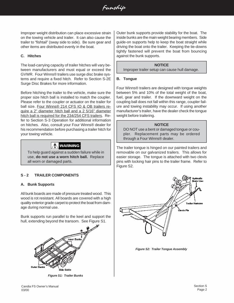
Section SPage 2
Candia FS Owner’s Manual03/00
Improper weight distribution can place excessive strainon the towing vehicle and trailer. It can also cause thetrailer to “fishtail” (sway side to side). Be sure gear andother items are distributed evenly in the boat.
C. Hitches
The load-carrying capacity of trailer hitches will vary be-tween manufacturers and must equal or exceed theGVWR. Four Winns® trailers use surge disc brake sys-tems and require a fixed hitch. Refer to Section S-2ESurge Disc Brakes for more information.
Before hitching the trailer to the vehicle, make sure theproper size hitch ball is installed to match the coupler.Please refer to the coupler or actuator on the trailer forball size. Four Winns® 214 CFS IO & OB trailers re-quire a 2" diameter hitch ball and a 2 5/16” diameterhitch ball is required for the 234/254 CFS trailers. Re-fer to Section S-3 Operation for additional informationon hitches. Also, consult your Four Winns® dealer forhis recommendation before purchasing a trailer hitch foryour towing vehicle.
To help guard against a sudden failure while inuse, do not use a worn hitch ball. Replaceall worn or damaged parts.
S - 2 TRAILER COMPONENTS
A. Bunk Supports
All bunk boards are made of pressure treated wood. Thiswood is rot resistant. All boards are covered with a highquality exterior grade carpet to protect the boat from dam-age during normal use.
Bunk supports run parallel to the keel and support thehull, extending beyond the transom. See Figure S1.
Outer bunk supports provide stability for the boat. Theinside bunks are the main weight bearing members. Sideguide-on supports help to keep the boat straight whiledriving the boat onto the trailer. Keeping the tie-downstightly fastened will prevent the boat from bouncingagainst the bunk supports.
NOTICEImproper trailer setup can cause hull damage.
B. Tongue
Four Winns® trailers are designed with tongue weightsbetween 5% and 10% of the total weight of the boat,fuel, gear and trailer. If the downward weight on thecoupling ball does not fall within this range, coupler fail-ure and towing instability may occur. If using anothermanufacturer’s trailer, have the dealer check the tongueweight before trailering.
NOTICEDO NOT use a bent or damaged tongue or cou-pler. Replacement parts may be orderedthrough a Four Winns® dealer.
The trailer tongue is hinged on our painted trailers andremovable on our galvanized trailers. This allows foreasier storage. The tongue is attached with two clevispins with locking hair pins to the trailer frame. Refer toFigure S2.
Figure S2: Trailer Tongue Assembly
Figure S1: Trailer Bunks
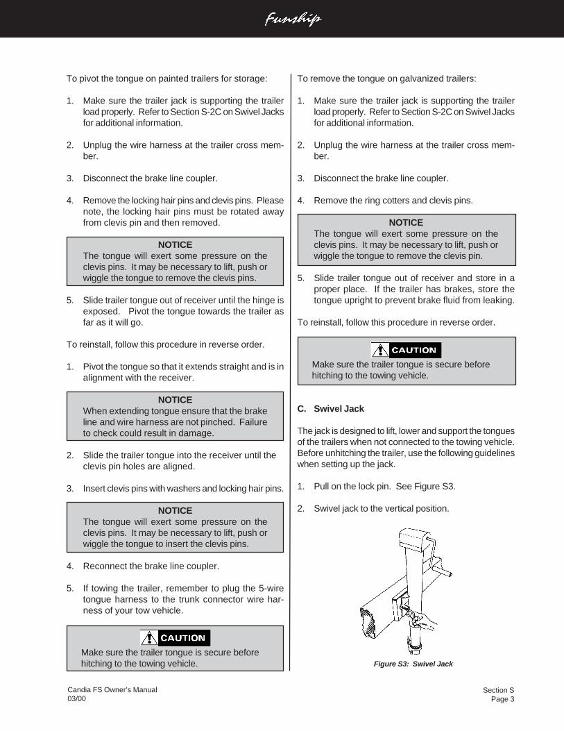
Section SPage 3
Candia FS Owner’s Manual03/00
To remove the tongue on galvanized trailers:
1. Make sure the trailer jack is supporting the trailerload properly. Refer to Section S-2C on Swivel Jacksfor additional information.
2. Unplug the wire harness at the trailer cross mem-ber.
3. Disconnect the brake line coupler.
4. Remove the ring cotters and clevis pins.
NOTICEThe tongue will exert some pressure on theclevis pins. It may be necessary to lift, push orwiggle the tongue to remove the clevis pin.
5. Slide trailer tongue out of receiver and store in aproper place. If the trailer has brakes, store thetongue upright to prevent brake fluid from leaking.
To reinstall, follow this procedure in reverse order.
Make sure the trailer tongue is secure before hitching to the towing vehicle.
C. Swivel Jack
The jack is designed to lift, lower and support the tonguesof the trailers when not connected to the towing vehicle.Before unhitching the trailer, use the following guidelineswhen setting up the jack.
1. Pull on the lock pin. See Figure S3.
2. Swivel jack to the vertical position.
Figure S3: Swivel Jack
To pivot the tongue on painted trailers for storage:
1. Make sure the trailer jack is supporting the trailerload properly. Refer to Section S-2C on Swivel Jacksfor additional information.
2. Unplug the wire harness at the trailer cross mem-ber.
3. Disconnect the brake line coupler.
4. Remove the locking hair pins and clevis pins. Pleasenote, the locking hair pins must be rotated awayfrom clevis pin and then removed.
NOTICEThe tongue will exert some pressure on theclevis pins. It may be necessary to lift, push orwiggle the tongue to remove the clevis pins.
5. Slide trailer tongue out of receiver until the hinge isexposed. Pivot the tongue towards the trailer asfar as it will go.
To reinstall, follow this procedure in reverse order.
1. Pivot the tongue so that it extends straight and is inalignment with the receiver.
NOTICEWhen extending tongue ensure that the brakeline and wire harness are not pinched. Failureto check could result in damage.
2. Slide the trailer tongue into the receiver until theclevis pin holes are aligned.
3. Insert clevis pins with washers and locking hair pins.
NOTICEThe tongue will exert some pressure on theclevis pins. It may be necessary to lift, push orwiggle the tongue to insert the clevis pins.
4. Reconnect the brake line coupler.
5. If towing the trailer, remember to plug the 5-wiretongue harness to the trunk connector wire har-ness of your tow vehicle.
Make sure the trailer tongue is secure before hitching to the towing vehicle.
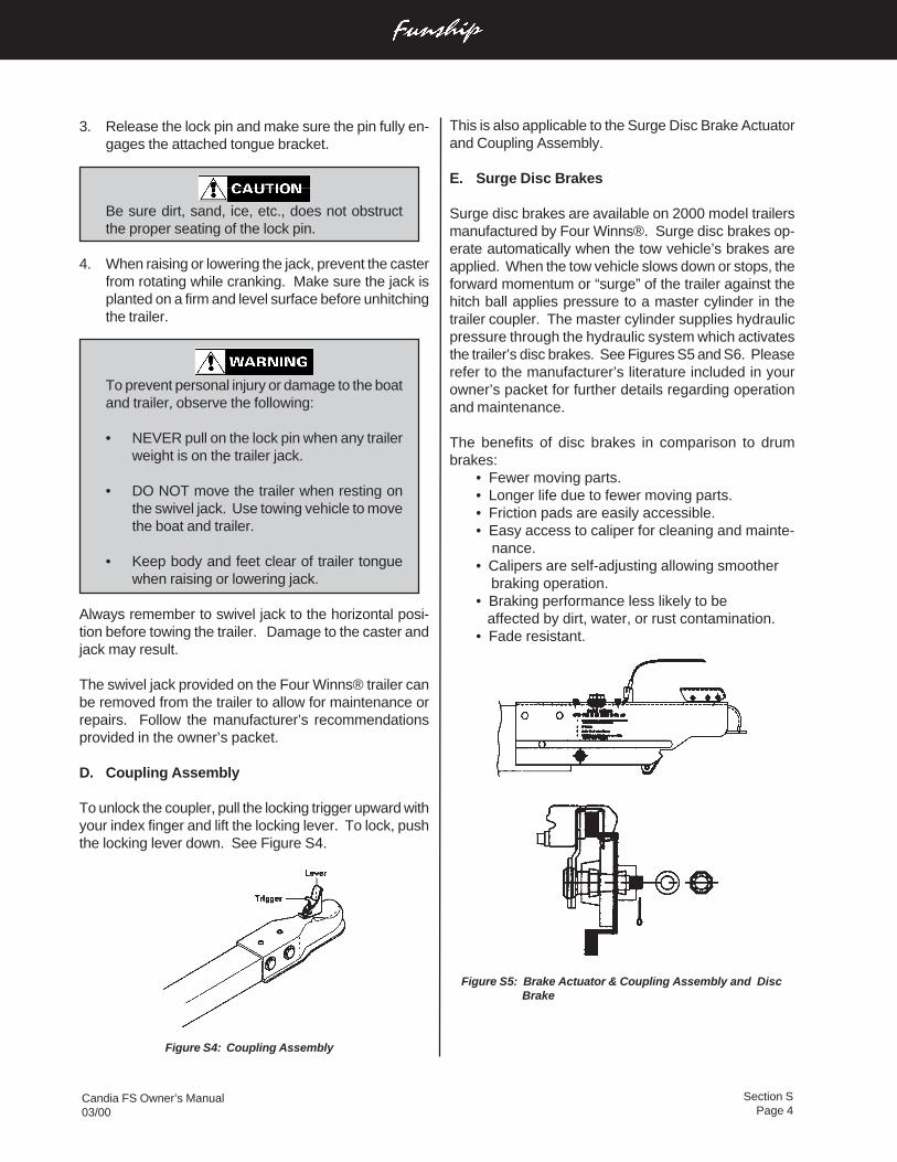
Section SPage 4
Candia FS Owner’s Manual03/00
3. Release the lock pin and make sure the pin fully en-gages the attached tongue bracket.
Be sure dirt, sand, ice, etc., does not obstructthe proper seating of the lock pin.
4. When raising or lowering the jack, prevent the casterfrom rotating while cranking. Make sure the jack isplanted on a firm and level surface before unhitchingthe trailer.
To prevent personal injury or damage to the boatand trailer, observe the following:
• NEVER pull on the lock pin when any trailerweight is on the trailer jack.
• DO NOT move the trailer when resting onthe swivel jack. Use towing vehicle to movethe boat and trailer.
• Keep body and feet clear of trailer tonguewhen raising or lowering jack.
Always remember to swivel jack to the horizontal posi-tion before towing the trailer. Damage to the caster andjack may result.
The swivel jack provided on the Four Winns® trailer canbe removed from the trailer to allow for maintenance orrepairs. Follow the manufacturer’s recommendationsprovided in the owner’s packet.
D. Coupling Assembly
To unlock the coupler, pull the locking trigger upward withyour index finger and lift the locking lever. To lock, pushthe locking lever down. See Figure S4.
This is also applicable to the Surge Disc Brake Actuatorand Coupling Assembly.
E. Surge Disc Brakes
Surge disc brakes are available on 2000 model trailersmanufactured by Four Winns®. Surge disc brakes op-erate automatically when the tow vehicle’s brakes areapplied. When the tow vehicle slows down or stops, theforward momentum or “surge” of the trailer against thehitch ball applies pressure to a master cylinder in thetrailer coupler. The master cylinder supplies hydraulicpressure through the hydraulic system which activatesthe trailer’s disc brakes. See Figures S5 and S6. Pleaserefer to the manufacturer’s literature included in yourowner’s packet for further details regarding operationand maintenance.
The benefits of disc brakes in comparison to drumbrakes:
• Fewer moving parts.• Longer life due to fewer moving parts.• Friction pads are easily accessible.• Easy access to caliper for cleaning and mainte- nance.• Calipers are self-adjusting allowing smoother braking operation.• Braking performance less likely to be affected by dirt, water, or rust contamination.• Fade resistant.
Figure S5: Brake Actuator & Coupling Assembly and Disc Brake
Figure S4: Coupling Assembly
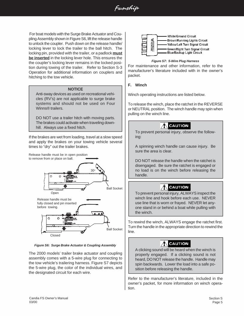
Section SPage 5
Candia FS Owner’s Manual03/00
For boat models with the Surge Brake Actuator and Cou-pling Assembly shown in Figure S6, lift the release handleto unlock the coupler. Push down on the release handle/locking lever to lock the trailer to the ball hitch. Thelocking pin, provided with the trailer, or a padlock mustbe inserted in the locking lever hole. This ensures thethe coupler’s locking lever remains in the locked posi-tion during towing of the trailer. Refer to Section S-3Operation for additional information on couplers andhitching to the tow vehicle.
NOTICEAnti-sway devices as used on recreational vehi-cles (RV’s) are not applicable to surge brakesystems and should not be used on FourWinns® trailers.
DO NOT use a trailer hitch with moving parts.The brakes could activate when traveling down-hill. Always use a fixed hitch.
If the brakes are wet from loading, travel at a slow speedand apply the brakes on your towing vehicle severaltimes to “dry” out the trailer brakes.
Figure S6: Surge Brake Actuator & Coupling Assembly
The 2000 models’ trailer brake actuator and couplingassembly comes with a 5-wire plug for connecting tothe tow vehicle’s trailering harness. Figure S7 depictsthe 5-wire plug, the color of the individual wires, andthe designated circuit for each wire.
Ball Socket
Ball Socket
30O
Release handle must be in open positionto remove from or place on ball.
Open
Release handle must befully closed and pin insertedbefore towing.
Closed
Figure S7: 5-Wire Plug Harness
For maintenance and other information, refer to themanufacturer’s literature included with in the owner’spacket.
F. Winch
Winch operating instructions are listed below.
To release the winch, place the ratchet in the REVERSEor NEUTRAL position. The winch handle may spin whenpulling on the winch line.
To prevent personal injury, observe the follow-ing:
A spinning winch handle can cause injury. Besure the area is clear.
DO NOT release the handle when the ratchet isdisengaged. Be sure the ratchet is engaged orno load is on the winch before releasing thehandle.
To prevent personal injury, ALWAYS inspect thewinch line and hook before each use. NEVERuse line that is worn or frayed. NEVER let any-one stand in or behind a boat while pulling withthe winch.
To rewind the winch, ALWAYS engage the ratchet first.Turn the handle in the appropriate direction to rewind theline.
A clicking sound will be heard when the winch isproperly engaged. If a clicking sound is notheard, DO NOT release the handle. Handle mayspin backwards. Lower the load into a safe po-sition before releasing the handle.
Refer to the manufacturer’s literature, included in theowner’s packet, for more information on winch opera-tion.
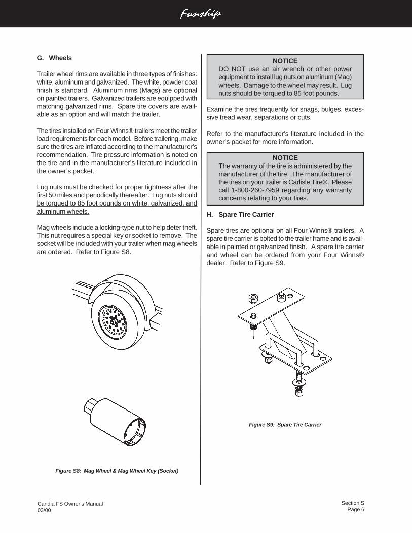
Section SPage 6
Candia FS Owner’s Manual03/00
NOTICEDO NOT use an air wrench or other powerequipment to install lug nuts on aluminum (Mag)wheels. Damage to the wheel may result. Lugnuts should be torqued to 85 foot pounds.
Examine the tires frequently for snags, bulges, exces-sive tread wear, separations or cuts.
Refer to the manufacturer’s literature included in theowner’s packet for more information.
NOTICEThe warranty of the tire is administered by themanufacturer of the tire. The manufacturer ofthe tires on your trailer is Carlisle Tire®. Pleasecall 1-800-260-7959 regarding any warrantyconcerns relating to your tires.
H. Spare Tire Carrier
Spare tires are optional on all Four Winns® trailers. Aspare tire carrier is bolted to the trailer frame and is avail-able in painted or galvanized finish. A spare tire carrierand wheel can be ordered from your Four Winns®dealer. Refer to Figure S9.
Figure S9: Spare Tire Carrier
G. Wheels
Trailer wheel rims are available in three types of finishes:white, aluminum and galvanized. The white, powder coatfinish is standard. Aluminum rims (Mags) are optionalon painted trailers. Galvanized trailers are equipped withmatching galvanized rims. Spare tire covers are avail-able as an option and will match the trailer.
The tires installed on Four Winns® trailers meet the trailerload requirements for each model. Before trailering, makesure the tires are inflated according to the manufacturer’srecommendation. Tire pressure information is noted onthe tire and in the manufacturer’s literature included inthe owner’s packet.
Lug nuts must be checked for proper tightness after thefirst 50 miles and periodically thereafter. Lug nuts shouldbe torqued to 85 foot pounds on white, galvanized, andaluminum wheels.
Mag wheels include a locking-type nut to help deter theft.This nut requires a special key or socket to remove. Thesocket will be included with your trailer when mag wheelsare ordered. Refer to Figure S8.
Figure S8: Mag Wheel & Mag Wheel Key (Socket)
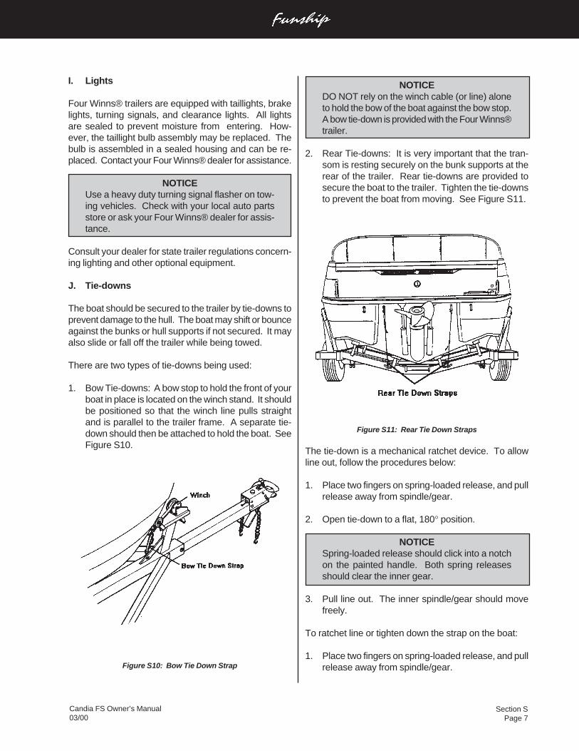
Section SPage 7
Candia FS Owner’s Manual03/00
I. Lights
Four Winns® trailers are equipped with taillights, brakelights, turning signals, and clearance lights. All lightsare sealed to prevent moisture from entering. How-ever, the taillight bulb assembly may be replaced. Thebulb is assembled in a sealed housing and can be re-placed. Contact your Four Winns® dealer for assistance.
NOTICEUse a heavy duty turning signal flasher on tow-ing vehicles. Check with your local auto partsstore or ask your Four Winns® dealer for assis-tance.
Consult your dealer for state trailer regulations concern-ing lighting and other optional equipment.
J. Tie-downs
The boat should be secured to the trailer by tie-downs toprevent damage to the hull. The boat may shift or bounceagainst the bunks or hull supports if not secured. It mayalso slide or fall off the trailer while being towed.
There are two types of tie-downs being used:
1. Bow Tie-downs: A bow stop to hold the front of yourboat in place is located on the winch stand. It shouldbe positioned so that the winch line pulls straightand is parallel to the trailer frame. A separate tie-down should then be attached to hold the boat. SeeFigure S10.
Figure S10: Bow Tie Down Strap
NOTICEDO NOT rely on the winch cable (or line) aloneto hold the bow of the boat against the bow stop.A bow tie-down is provided with the Four Winns®trailer.
2. Rear Tie-downs: It is very important that the tran-som is resting securely on the bunk supports at therear of the trailer. Rear tie-downs are provided tosecure the boat to the trailer. Tighten the tie-downsto prevent the boat from moving. See Figure S11.
Figure S11: Rear Tie Down Straps
The tie-down is a mechanical ratchet device. To allowline out, follow the procedures below:
1. Place two fingers on spring-loaded release, and pullrelease away from spindle/gear.
2. Open tie-down to a flat, 180° position.
NOTICESpring-loaded release should click into a notchon the painted handle. Both spring releasesshould clear the inner gear.
3. Pull line out. The inner spindle/gear should movefreely.
To ratchet line or tighten down the strap on the boat:
1. Place two fingers on spring-loaded release, and pullrelease away from spindle/gear.
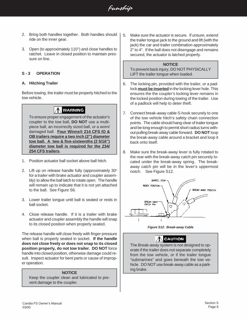
Section SPage 8
Candia FS Owner’s Manual03/00
2. Bring both handles together. Both handles shouldride on the inner gear.
3. Open (to approximately 110°) and close handles toratchet. Leave in closed position to maintain pres-sure on line.
S - 3 OPERATION
A. Hitching Trailer
Before towing, the trailer must be properly hitched to thetow vehicle.
To ensure proper engagement of the actuator’scoupler to the tow ball, DO NOT use a multi-piece ball, an incorrectly sized ball, or a worn/damaged ball. Four Winns® 214 CFS IO &OB trailers require a two inch (2”) diametertow ball. A two & five-sixteenths (2 5/16”)diameter tow ball is required for the 234/254 CFS trailers.
1. Position actuator ball socket above ball hitch.
2. Lift up on release handle fully (approximately 30o
for a trailer with brake actuator and coupler assem-bly) to allow the ball latch to rotate open. The handlewill remain up to indicate that it is not yet attachedto the ball. See Figure S6.
3. Lower trailer tongue until ball is seated or rests inball socket.
4. Close release handle. If it is a trailer with brakeactuator and coupler assembly the handle will snapto its closed position when properly seated.
The release handle will close freely with finger pressurewhen ball is properly seated in socket. If the handledoes not close freely or does not snap to its closedposition properly, do not tow trailer. DO NOT forcehandle into closed position, otherwise damage could re-sult. Inspect actuator for bent parts or cause of improp-er operation.
NOTICEKeep the coupler clean and lubricated to pre-vent damage to the coupler.
5. Make sure the actuator is secure. If unsure, extendthe trailer tongue jack to the ground and lift (with thejack) the car and trailer combination approximately2" to 4". If the ball does not disengage and remainssecured, the actuator is latched properly.
NOTICETo prevent back injury, DO NOT PHYSICALLYLIFT the trailer tongue when loaded.
6. The locking pin, provided with the trailer, or a pad-lock must be inserted in the locking lever hole. Thisensures the the coupler’s locking lever remains inthe locked position during towing of the trailer. Useof a padlock will help to deter theft.
7. Connect break-away cable S-hook securely to oneof the tow vehicle hitch’s safety chain connectionpoints. The cable should hang clear of trailer tongueand be long enough to permit short radius turns with-out pulling break-away cable forward. DO NOT loopthe break-away cable around a bracket and loop itback onto itself.
8. Make sure the break-away lever is fully rotated tothe rear with the break-away catch pin securely lo-cated under the break-away spring. The break-away catch pin will be in the lever’s uppermostnotch. See Figure S12.
Figure S12: Break-away Cable
The Break-away system is not designed to op-erate if the trailer does not separate completelyfrom the tow vehicle, or if the trailer tongue“submarines” and goes beneath the tow ve-hicle. DO NOT use break-away cable as a park-ing brake.
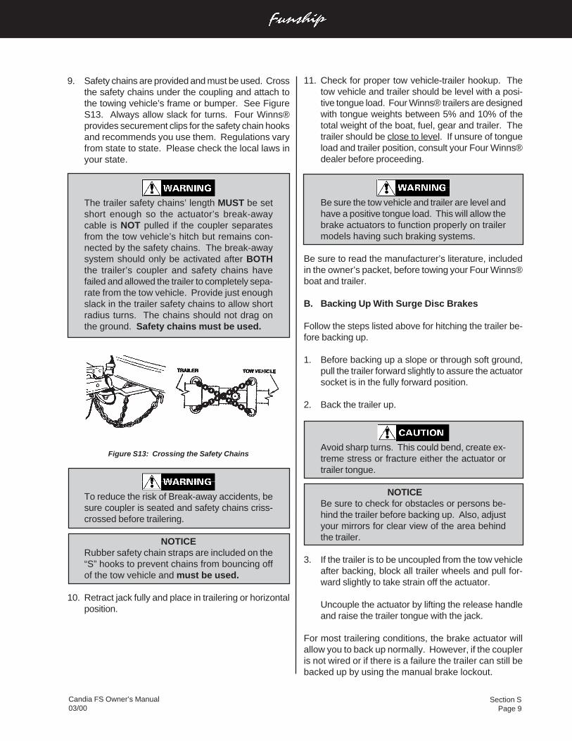
Section SPage 9
Candia FS Owner’s Manual03/00
9. Safety chains are provided and must be used. Crossthe safety chains under the coupling and attach tothe towing vehicle’s frame or bumper. See FigureS13. Always allow slack for turns. Four Winns®provides securement clips for the safety chain hooksand recommends you use them. Regulations varyfrom state to state. Please check the local laws inyour state.
The trailer safety chains’ length MUST be setshort enough so the actuator’s break-awaycable is NOT pulled if the coupler separatesfrom the tow vehicle’s hitch but remains con-nected by the safety chains. The break-awaysystem should only be activated after BOTHthe trailer’s coupler and safety chains havefailed and allowed the trailer to completely sepa-rate from the tow vehicle. Provide just enoughslack in the trailer safety chains to allow shortradius turns. The chains should not drag onthe ground. Safety chains must be used.
Figure S13: Crossing the Safety Chains
To reduce the risk of Break-away accidents, besure coupler is seated and safety chains criss-crossed before trailering.
NOTICERubber safety chain straps are included on the“S” hooks to prevent chains from bouncing offof the tow vehicle and must be used.
10. Retract jack fully and place in trailering or horizontalposition.
11. Check for proper tow vehicle-trailer hookup. Thetow vehicle and trailer should be level with a posi-tive tongue load. Four Winns® trailers are designedwith tongue weights between 5% and 10% of thetotal weight of the boat, fuel, gear and trailer. Thetrailer should be close to level. If unsure of tongueload and trailer position, consult your Four Winns®dealer before proceeding.
Be sure the tow vehicle and trailer are level andhave a positive tongue load. This will allow thebrake actuators to function properly on trailermodels having such braking systems.
Be sure to read the manufacturer’s literature, includedin the owner’s packet, before towing your Four Winns®boat and trailer.
B. Backing Up With Surge Disc Brakes
Follow the steps listed above for hitching the trailer be-fore backing up.
1. Before backing up a slope or through soft ground,pull the trailer forward slightly to assure the actuatorsocket is in the fully forward position.
2. Back the trailer up.
Avoid sharp turns. This could bend, create ex-treme stress or fracture either the actuator ortrailer tongue.
NOTICEBe sure to check for obstacles or persons be-hind the trailer before backing up. Also, adjustyour mirrors for clear view of the area behindthe trailer.
3. If the trailer is to be uncoupled from the tow vehicleafter backing, block all trailer wheels and pull for-ward slightly to take strain off the actuator.
Uncouple the actuator by lifting the release handleand raise the trailer tongue with the jack.
For most trailering conditions, the brake actuator willallow you to back up normally. However, if the coupleris not wired or if there is a failure the trailer can still bebacked up by using the manual brake lockout.
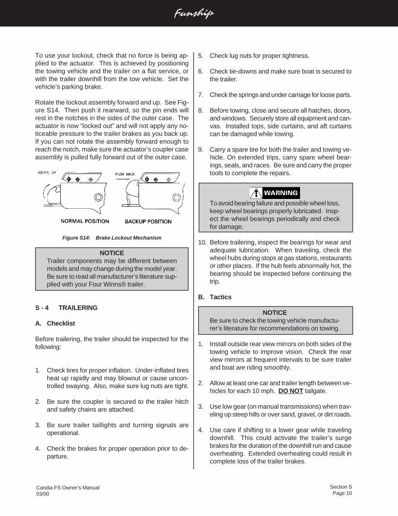
Section SPage 10
Candia FS Owner’s Manual03/00
To use your lockout, check that no force is being ap-plied to the actuator. This is achieved by positioningthe towing vehicle and the trailer on a flat service, orwith the trailer downhill from the tow vehicle. Set thevehicle’s parking brake.
Rotate the lockout assembly forward and up. See Fig-ure S14. Then push it rearward, so the pin ends willrest in the notches in the sides of the outer case. Theactuator is now “locked out” and will not apply any no-ticeable pressure to the trailer brakes as you back up.If you can not rotate the assembly forward enough toreach the notch, make sure the actuator’s coupler caseassembly is pulled fully forward out of the outer case.
Figure S14: Brake Lockout Mechanism
NOTICETrailer components may be different betweenmodels and may change during the model year.Be sure to read all manufacturer’s literature sup-plied with your Four Winns® trailer.
S - 4 TRAILERING
A. Checklist
Before trailering, the trailer should be inspected for thefollowing:
1. Check tires for proper inflation. Under-inflated tiresheat up rapidly and may blowout or cause uncon-trolled swaying. Also, make sure lug nuts are tight.
2. Be sure the coupler is secured to the trailer hitchand safety chains are attached.
3. Be sure trailer taillights and turning signals areoperational.
4. Check the brakes for proper operation prior to de-parture.
5. Check lug nuts for proper tightness.
6. Check tie-downs and make sure boat is secured tothe trailer.
7. Check the springs and under carriage for loose parts.
8. Before towing, close and secure all hatches, doors,and windows. Securely store all equipment and can-vas. Installed tops, side curtains, and aft curtainscan be damaged while towing.
9. Carry a spare tire for both the trailer and towing ve-hicle. On extended trips, carry spare wheel bear-ings, seals, and races. Be sure and carry the propertools to complete the repairs.
To avoid bearing failure and possible wheel loss,keep wheel bearings properly lubricated. Insp-ect the wheel bearings periodically and checkfor damage.
10. Before trailering, inspect the bearings for wear andadequate lubrication. When traveling, check thewheel hubs during stops at gas stations, restaurantsor other places. If the hub feels abnormally hot, thebearing should be inspected before continuing thetrip.
B. Tactics
NOTICEBe sure to check the towing vehicle manufactu-rer’s literature for recommendations on towing.
1. Install outside rear view mirrors on both sides of thetowing vehicle to improve vision. Check the rearview mirrors at frequent intervals to be sure trailerand boat are riding smoothly.
2. Allow at least one car and trailer length between ve-hicles for each 10 mph. DO NOT tailgate.
3. Use low gear (on manual transmissions) when trav-eling up steep hills or over sand, gravel, or dirt roads.
4. Use care if shifting to a lower gear while travelingdownhill. This could activate the trailer’s surgebrakes for the duration of the downhill run and causeoverheating. Extended overheating could result incomplete loss of the trailer brakes.
Section SPage 11
Candia FS Owner’s Manual03/00
C. Swivel Jack
Keep the swivel jack clean of dirt, tar, and mud. Lubri-cate every six months. The swivel jack’s inner ram shouldbe lubricated with SAE 30 weight oil. The top cover maybe removed to lubricate the gears with wheel bearinggrease.
Replace all worn and damaged parts. ALWAYS use themanufacturer’s replacement parts. Replacement partsmay be ordered through your Four Winns® dealer.
For more information on maintenance, refer to themanufacturer’s literature included in the owner’s packet.
D. Brake Actuator & Coupling Assembly
When storing or parking your trailer, keep the brake ac-tuator and coupling assembly (coupler) off the ground toprevent dirt buildup in the ball socket. Keep the couplerclean of dirt, tar, and mud. Lubricate the coupler withSAE 30 weight oil every six months or as often as neces-sary. Replace any worn or defective parts. If the cou-pler is damaged, contact your Four Winns® dealer forreplacement parts. DO NOT use a damaged or bentcoupler assembly.
For more information on maintenance, refer to themanufacturer’s literature included in the owner’s packet.
NOTICEThe trailer should be set up at a slight angle toallow for water to drain aft in the boat.
E. Winch
The winch should be kept clean of dirt, ice, paint, etc.,and the spur gears should have a film of grease on themat all times. Apply several drops of SAE 30 weight oil tothe ratchet pawl mechanism, bushings and pinion shaftthreads twice per season.
Replace any worn or damaged parts. For more infor-mation on maintenance, refer to the manufacturer’s litera-ture included in the owner’s packet.
F. Lights
Inspect wiring for cuts or bare wire which could causeelectrical shorts. Repair or replace defective wiring.Replace cracked or damaged lens and always carryspare bulbs. Replacement parts may be ordered througha Four Winns® dealer.
To help prevent overheating, slow down while ap-proaching the crest of a hill and maintain a slow,controlled downhill speed. Apply brakes in short in-tervals to allow time between braking for the brakesto cool off.
5. When rounding turns on highways or streets, DONOT cut corners. Also, travel slowly over railroadtracks.
6. If the trailer begins to “fishtail” when accelerating,reduce speed until it ceases. If the trailer “fishtails”again during acceleration, stop to investigate thecause of the problem. Check for improper trailerload and uneven weight distribution inside the boat.Check the winch line and tie-downs. Also check thetires for proper inflation or damage. If necessary,redistribute the load before continuing.
For additional information on trailering, refer to the “Boat-ing Basics” manual included in the owner’s packet.
S - 5 MAINTENANCE
A. Care of Exterior Finish
When using the trailer, keep in mind the paint can scratchand become marred during normal use. In most cases,touch-up paint can be ordered. Please contact a FourWinns® dealer for assistance.
Some maintenance is required to maintain the finish andminimize rusting. The trailer should be washed andrinsed with clean water immediately after each use. Ongalvanized trailers, rinse only with clean water. Depend-ing upon use, waxing is recommended twice a year. Usepaste wax designed for enamel paint.
B. Bunks
The bunks should be replaced if they are cracked,warped, or evidence of dry-rot is found. The replace-ment boards should be treated lumber of the same lengthand width.
DO NOT burn damaged or broken bunks. Toxicfumes will be released. Dispose of bunks prop-erly.
Section SPage 12
Candia FS Owner’s Manual03/00
J. Bearings
Wheel bearings and seals should be inspected at thesame time as brakes. Have worn or defective parts re-placed. Grease bearings and seals at this time and atthe end of the boating season. Bearing Protectorsshould be greased three to four times a year. A greasefitting is provided.
Four Winns® uses the Accu-Lube™ bearing protec-tion system on its trailers. The Accu-Lube™ design issubmersible and provides for grease flow that com-pletely repacks and protects the bearings. This lubri-cation system disallows water entry, thus extending thelife of the bearings, spindle and hub.
Lubricate the bearings as follows:
1. Remove the rubber plug.
2. Insert the grease gun into the grease fitting. Pump grease until old grease comes back out the front.
3. Remove old grease and reinstall rubber plug.
NOTICEMost bearing failures are due to improper main-tenance. Be sure to inspect bearings and sealsas noted in Section S-6B and refer to themanufacturer’s literature included with yourtrailer.
S - 6 AXLE INSPECTION & REPAIRS
As a general rule, repairs and maintenance should beperformed by qualified servicing personnel. Our axlemanufacturer recommends that a certified mechanicshould be consulted on the following items:
1. Broken axle2. Broken spring3. Worn spring eye bushing parts4. Sagging springs5. Welding fatigue6. Serious leakage of seal7. Tire wear8. Loose or worn suspension parts9. All brake related adjustments, inspections and prob-
lems
G. Tie-downs
Replace frayed or damaged tie-downs. Periodically, lu-bricate the ratchet mechanism with a fine oil or siliconespray. Replacement parts may be ordered through aFour Winns® dealer.
H. Wheels
Some maintenance is required to maintain the finish andretard rusting of painted rims. The wheels should becleaned with dishwashing soap and water and rinsedwith clean water immediately after each use. Waxing isrecommended three to four times each year.
Aluminum wheel rims may be cleaned with dishwashingsoap and water. However, cleaning products specifi-cally for aluminum are available and can be used. Clean-ers may be obtained from Four Winns® dealers and yourlocal auto parts stores. The Mag wheel manufacturerrecommends a product by Priority One® called Pro-LongAluminum/Chrome Wheel Protectant™. Galvanized rimsshould be rinsed only with clean water immediately aftereach use.
NOTICEALWAYS read the manufacturer’s instructionson the label before using any product.
I. Brakes
Keep the actuator clean of dirt, tar, and mud. The actua-tor and internal parts should be lubricated at all timeswith SAE 30 weight oil. The hitch ball may be lubricatedwith automotive grease or lubricant made for hitch balls.
Periodically inspect the brake system for leaks. Checkall hoses for cuts or wear. Replace all defective hoses.The master cylinder should be filled within 1/2 inch fromthe top of the reservoir.
At the beginning of each year, inspect the brakes forexcessive wear, have linings replaced if necessary.
If the brakes need bleeding, consult your Four Winns®dealer for assistance. If unavailable, a brake or autorepair facility can perform the repair.
Refer to the manufacturer’s literature included in theowner’s packet for additional information on the brakesystem.
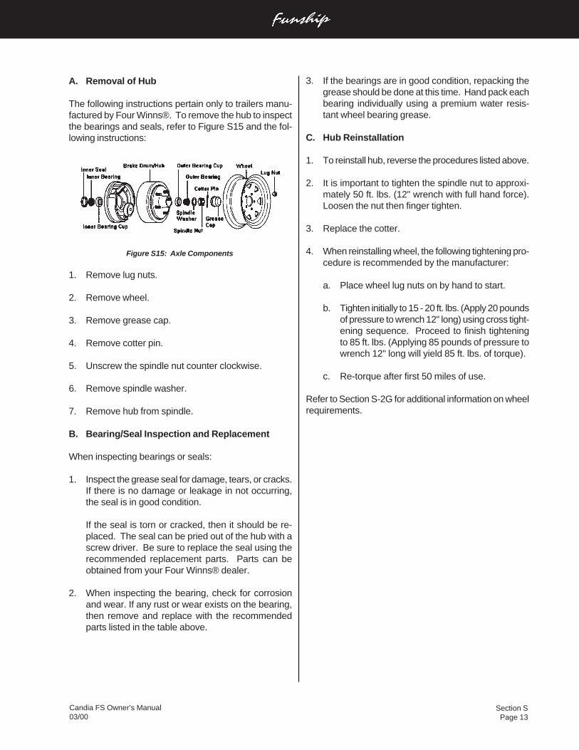
Section SPage 13
Candia FS Owner’s Manual03/00
A. Removal of Hub
The following instructions pertain only to trailers manu-factured by Four Winns®. To remove the hub to inspectthe bearings and seals, refer to Figure S15 and the fol-lowing instructions:
Figure S15: Axle Components
1. Remove lug nuts.
2. Remove wheel.
3. Remove grease cap.
4. Remove cotter pin.
5. Unscrew the spindle nut counter clockwise.
6. Remove spindle washer.
7. Remove hub from spindle.
B. Bearing/Seal Inspection and Replacement
When inspecting bearings or seals:
1. Inspect the grease seal for damage, tears, or cracks.If there is no damage or leakage in not occurring,the seal is in good condition.
If the seal is torn or cracked, then it should be re-placed. The seal can be pried out of the hub with ascrew driver. Be sure to replace the seal using therecommended replacement parts. Parts can beobtained from your Four Winns® dealer.
2. When inspecting the bearing, check for corrosionand wear. If any rust or wear exists on the bearing,then remove and replace with the recommendedparts listed in the table above.
3. If the bearings are in good condition, repacking thegrease should be done at this time. Hand pack eachbearing individually using a premium water resis-tant wheel bearing grease.
C. Hub Reinstallation
1. To reinstall hub, reverse the procedures listed above.
2. It is important to tighten the spindle nut to approxi-mately 50 ft. lbs. (12" wrench with full hand force).Loosen the nut then finger tighten.
3. Replace the cotter.
4. When reinstalling wheel, the following tightening pro-cedure is recommended by the manufacturer:
a. Place wheel lug nuts on by hand to start.
b. Tighten initially to 15 - 20 ft. lbs. (Apply 20 poundsof pressure to wrench 12" long) using cross tight-ening sequence. Proceed to finish tighteningto 85 ft. lbs. (Applying 85 pounds of pressure towrench 12" long will yield 85 ft. lbs. of torque).
c. Re-torque after first 50 miles of use.
Refer to Section S-2G for additional information on wheelrequirements.
GlossaryPage 1
Candia FS Owner’s Manual03/00
GLOSSARY
ABAFT - Toward the rear of a boat.
ABEAM - At right angles to the keel of the boat.
ABOARD - On the boat.
ABREAST - Side by side.
ADRIFT - Loose, not on moorings or towline.
AFT - Moving toward the stern, you are going aft.
AGROUND - Stuck fast to the bottom.
AHEAD - In a forward direction.
ALEE - Away from the direction of the wind; opposite ofwindward.
ALOFT - Above the deck.
AMIDSHIPS - 1. An object or area midway between thebow and stern. 2. An object or area midway between theport side and the starboard side of a vessel.
AMPERE - The standard unit used to measure the drawof an electrical current.
ANCHOR RODE OR ROPE - The line (chain) connect-ing a vessel to its anchor.
ANCHOR BALL - A black, circular, day signal hoisted toshow that a vessel is anchored. Replaced at dusk by theanchor light.
ASTERN - Anywhere behind the boat, a reverse direc-tion, opposite of ahead.
ATHWARTSHIPS - A line, or anything else, running per-pendicular to the fore-and-aft center line of a boat.
BATTEN - A strip of wood or metal used to securetarpaulin(s) in place over a hatch. To batten down meansto secure for rough weather.
BEAM - 1. The widest distance across a boat from theoutside skin on one side to the outside skin on the other.2. A transverse structural member that stiffens and sup-ports a portion of the deck.
BEAM WIND - A wind blowing against the side of thevessel, perpendicular to the long axis of the vessel.
BILGE - The lowest interior area of a hull, used to col-lect water that has entered.
BILGE PUMP - A pump intended for removal of spray,rainwater, and the normal accumulation of water due toseepage and spillage; not intended for damage control.
BINNACLE - The stand or support for a magnetic com-pass occasionally used to mean helm.
BITT - A heavy and firmly mounted piece of wood ormetal used for securing lines.
BLOCK - A wooden or metal case enclosing one or morepulleys and having a hook, eye, or strap by which it maybe attached.
BOLLARD - A single post (wood, metal, or concrete) ona dock, pier, or wharf used to secure a vessel’s lines.
BONDING - The electrical connection of exposed me-tallic, non-current carrying components to a commonpoint on the main engine block.
BOW - The front end of the boat.
BOW LINE - A docking line leading from the bow.
BREAKER - A single breaking, plunging or spilling wave.
BREAKER LINE - The outer limit of the surf. However,all breakers may not be in a line. They can occur out-side the breaker line.
BRIDGE - The main vessel control station.
BROACH - The turning of a boat parallel to the waves,subjecting it to possible capsizing.
BULKHEADS - The interior walls of a boat.
BULWARK - The side of a vessel when carried abovethe level of the deck.
BUOY - An anchored float used for marking a positionon the water, a hazard, or a shoal.
GlossaryPage 2
Candia FS Owner’s Manual03/00
CAPSIZE - To turn over.
CAPSTAN - A machine that moves a cylindrical deviceon a shaft for the purpose of hauling up an anchor.
CAST OFF - To let go.
CATAMARAN - A twin-hulled boat, with the hulls beingside-by-side.
CHINE - The intersection of a boat’s bottom and side. Ifthis intersection is rounded, it is a “soft” chine. If theintersection is squared off, it is a “hard” chine.
CHOCK - 1. A fitting or hole in a railing or deck throughwhich a mooring or anchor line is routed. 2. A wedgeused to secure an item in place.
CIRCUIT BREAKER - A device used to interrupt an elec-trical circuit when current flow exceeds a predeterminedlevel.
CLEAT - A double-ended deck fitting to which lines aresecured; usually anvil-shaped.
COAMINGS - Raised lips around cockpits or hatchesused to keep water from entering
COCKPIT - An exposed deck area (usually aft) that issubstantially lower than the adjacent deck.
COMBER - A wave on the point of breaking. A comberhas a thin line of white water on its crest, known as “feath-ering.”
COMPANIONWAY - The steps or ladder leading down-ward from a deck.
COMPARTMENTS - Rooms divided by bulkheads.
COUNTER - The overhang at the stern of a boat.
CRADLE - A framework, generally made of wood, usedto support a boat when it is out of the water.
CREST - The top of a wave, breaker or swell.
CUDDY - A small sheltered cabin in a boat.
CURRENT -1. The movement of water, 2. The flow ofelectrical charge.
DEAD AHEAD - Directly in front of the boat.
DEAD RECKONING - A plot of courses steered and dis-tances traveled through the water.
DECK - A permanent covering over a compartment, hullor any part thereof.
DINGHY - A small, open boat used for ship to shoretransportation.
DISPLACEMENT - The weight of water dislocated bythe hull of a vessel.
DISPLACEMENT HULL - A hull that “displaces” a vol-ume of water equal to the weight of the boat. A hulldesigned to run in the water rather than on top of thewater. When a displacement hull moves through thewater, it pushes that water out of the way. Water willthen flow around the hull and fill the “hole” the boat leavesastern.
DOCUMENTED VESSEL - Documented yachts havebeen specially registered with the U.S. Coast Guard. Alldocumented yachts must have their name and home(hailing) port marked on some conspicuous place on thehull. Numbering is not required. Advantages includelegal authority to fly the yacht ensign, privilege of record-ing bills of sale, and other instruments of title with fed-eral officials, and preferred status for mortgages. Docu-mentation does not exempt the unit from any State orFederal taxes. All safety and equipment regulations stillapply.
DOLPHIN - A group of piles driven close together andbound with wire cables into a single structure.
DRAFT - 1. The depth of a boat from the actual waterline to the bottom of the lowest part of the boat (e.g., thepropeller tip or rudder). 2. The depth of water necessaryto float a boat.
DROGUE - Any device streamed astern to check avessel’s speed, or to keep its stern up to the waves in afollowing sea.
DYE MARKER - A brightly colored chemical that spreadswhen released into water; normally used to attract atten-tion.
EBB TIDE - A receding tide.
EVEN KEEL - To be floating evenly without listing to ei-ther side.
GlossaryPage 3
Candia FS Owner’s Manual03/00
EXHAUST SYSTEM - The means by which the hot en-gine (or generator) exhaust gases are moved from theengine to an outboard port and then released into atmo-sphere.
EYE SPLICE - A permanent loop spliced in the end of aline.
FAST - Said of an object that is secured to another.
FATHOM - Six feet.
FENDER - A device (usually constructed of rubber orplastic) positioned so as to absorb the impact betweenvessels or dock.
FETCH - The unobstructed distance that the wind canblow over the water to create waves.
FLARE - 1. Outboard curve of the hull as it comes up theside from the waterline; the reverse of tumble home. 2.A pyrotechnic device used for emergency signaling.
FLAT - A small deck that is built below decks, specifi-cally to support a piece of equipment.
FLEMISH - To coil down a line or rope on deck in a flat,circular, concentric arrangement.
FLOTSAM - Floating wreckage, trash or debris.
FLUKE - The palm of an anchor.
FOAM CREST - The top of the foaming water that speedstoward the beach after a wave has broken, commonlyreferred to as “white water.”
FOLLOWING SEA - A sea (waves) moving in the samedirection as a vessel.
FORE-AND-AFT - A line, or anything else, that runs par-allel to the longitudinal center line of a boat.
FOREFOOT - The portion of a vessel’s keel that curvesupward to meet the stem.
FOREPEAK - A compartment in the bow of a boat.
FORWARD - Toward the bow.
FREEBOARD - The minimum vertical distance from thesurface of the water to the gunwale.
FREQUENCY - The number of crests passing a fixedpoint at a given time.
FRONTS - Where opposing warm and cold air massesmeet, generally producing a band of wet, stormy weatherwherever they meet.
GALLEY - The kitchen area of a boat.
GALVANIC CORROSION - A potential electrical differ-ence exists between dissimilar metals immersed in aconductive solution (e.g., salt water). If these metalstouch or are otherwise electrically connected, this po-tential difference produces an electron flow betweenthem. The attack on the less corrosion resistant metal isusually increased and the attack on the more resistantmetal is decreased, as compared to when these metalsare not touching.
GANGWAY - The area of a ship’s side where peopleboard and disembark.
GASKET - A strip of sealing material, usually rubber, setalong the edge of a water or gas tight door, port, cover orhatch.
GELCOAT - The thin outer layer of pigmented plasticcovering a fiberglass vessel.
GLAND - The movable part of a stuffing box, which whentightened, compresses the packing.
GROUND - Electrical term meaning the electrical po-tential of the earth’s surface, which is zero.
GROUND SPEED - A vessel’s speed made good overthe earth’s surface along a course or track.
GROUND TACKLE - The anchor, anchor rodes, andother fittings that are used to secure a vessel at anchoror dockside.
GUNWALE - 1. The line where the upper deck and thehull meet. 2. The upper edge of a boat’s side.
HALYARD - A line used to hoist a flag or pennant.
HATCHES - Cover on hatchways.
HATCHWAYS - Access ways through decks.
HARDTOP - A permanent cover over the cabin or cock-pit.
GlossaryPage 4
Candia FS Owner’s Manual03/00
HAWSER - A heavy rope or cable used for mooring ortowing.
HEAD - A toilet or lavatory area.
HEADING - The direction that a vessel is going with ref-erence to true, magnetic, or compass north.
HEADWAY - The forward motion of a vessel through thewater.
HEAVE TO - To bring a vessel up in a position where itwill maintain little or no headway, usually with the bowinto the wind.
HEAVY WEATHER - Stormy weather with high seas andstrong winds.
HEEL - To tip to one side.
HELM - The wheel or tiller that manually controls theboat’s steering system.
HELMSMAN - The individual steering the vessel.
HIGHS - A center of pressure surrounded by lower pres-sure on all sides. Caused by a mass of cooler, sinking,drier air. This raises the area ground level air pressureand provides clear skies.
HULL - The main body of a boat.
INBOARD - 1. From either the port or starboard side ofa boat toward the fore-and-aft centerline of a boat. 2.The dock side of a moored boat.
INLAND RULES - Nautical “Rules-of-the-Road” that ap-ply in U.S. lakes, rivers, and coastal waters.
INTERNATIONAL RULES - Nautical “Rules-of-the-Road”that are in effect by international agreement to the highseas.
ISOBARS - Lines of equal air pressure that connect allthe local points on a weather map. These lines are usu-ally closed and define high or low pressure air masses.
ISOTHERMS - Isotherms are lines that are similar toIsobars except that Isotherms connect all the points thatare of equal temperature.
JETSAM - Refuse that sinks when discharged overboard.
KEDGE(S) - One or more anchors set out from agrounded vessel, usually astern, to 1) keep it from beingdriven further aground and 2) to aid in refloating.
KEEL - 1. The centerline of a boat hull bottom runningfore and aft, 2. The backbone of a vessel.
KNOT - 1. A maritime unit of speed equal to one nauticalmile per hour (6076 feet). 2. A term for hitches and bends.
LANYARD - A short line made fast to an object to secureit.
LATITUDE - The measure of angular distance in degrees,minutes, and seconds, north or south of the equator.
LAZARETTE - Storage compartment in the deck at thestern.
LEADLINE - A weighted line used to take depth mea-surements.
LEE - The direction opposite that of the wind.
LEEWARD - Away from the wind.
LIST - A vessel that inclines to port or starboard.
LORAN - Long Range Navigation. An electronic systemwhereby a navigator can determine position regardlessof weather.
LONGITUDINAL - Running lengthwise.
LOWS - A region of low atmospheric pressure. Hurri-canes are extremely concentrated low pressure systems.
LUBBER LINE - A mark or line on the compass parallelto the keel indicating forward.
MAST - A spar that is set upright to support lighting, rig-ging, or sails.
MOORING - An arrangement for securing a boat to amooring buoy or pier.
NAVIGATION LIGHTS - A set of red and green or whitelights which must be shown by all vessels between duskand dawn.
OVERHEAD - A ceiling or roof of a vessel.
OVERBOARD - Over the side of the boat.
GlossaryPage 5
Candia FS Owner’s Manual03/00
OUTBOARD - 1. From the fore-and-aft centerline of aboat toward both the port and starboard sides. 2. Theseaward side of a moored boat. 3. An engine that ismounted externally onto the transom of a boat.
PAINTER - A line to the bow of a small boat used formaking fast.
PASSAGEWAY - A corridor or hallway aboard ship.
PENNANT - The line by which a boat is made fast to amooring buoy; also pendant.
PERSONAL FLOATATION DEVICE (PFD) - A life pre-server.
PIER - A loading platform that extends at an angle fromthe shore.
PILASTER - A rectangular structural support column thatis an extension of the port and starboard aft cabin sidesand which supports the hardtop and flybridge.
PILING - Support, or protection for wharves, piers, etc.
PITCH - 1. The vertical (up and down) motion of a bowin a seaway, about the athwartships axis. 2. The axialadvance of a propeller during one complete revolution.
PITCHPOLING - A boat being thrown end-over-end.
PLANING HULL - At slow speeds, a planing hull will dis-place water in the same manner as a displacement hull.As speed is increased, the hull provides a lifting effectup onto the surface of the water.
POINT - One of 32 points of the compass that is equal to11-1/4 degrees.
PORT - 1. Looking forward, the left side of a boat, 2. Aharbor, 3. An opening for light or ventilation or passageof material in the side of a boat.
PORT BEAM - The left-center of a boat.
PORT BOW - Facing the bow, the front left side.
PORT QUARTER - Looking forward, a vessel’s left rearsection.
QUARTER - The sides of a boat aft of amidships.
QUARTERING SEA - Sea coming on a boat’s quarter.
RED-RIGHT-RETURNING - A term for helmsmen thatbuoys and day markers are on the right when returningfrom seaward.
REEF - A shallow underwater barrier.
REEVE - To pass a line through a block or other open-ing.
RIDGES - High pressure fingers extending out from ahigh.
RODE - The anchor line or chain.
RUNNING LIGHTS - Lights required to be shown onboats underway between sundown and sunup.
RUDDER - A vertical plate for steering a boat.
SALON - The main social cabin on a vessel, usually thelargest area, occasionally referred to as the deckhouse.
SCREW - A propeller.
SCUPPER - A drain from the edge of a deck that dis-charges overboard.
SEACOCK - A positive action shut-off valve connecteddirectly to the hull seawater intake and discharge piping.
SERIES - A group of waves which seem to travel to-gether and at about the same speed.
SHACKLE - A “U” shaped connector with a pin or boltacross the open end.
SHAFT - The long, round member that connects the en-gine or transmission to the propeller.
SHAFT LOG - A fitting at the hull bottom where the shaftconnecting an engine to its propeller penetrates the hull.A shaft log permits the shaft to rotate while simultaneouslypreventing water from entering the hull.
SHEER - The top of the hull’s curvature at the deck linefrom the bow to the stern.
SHEER STRAKE - The upper edge of the hull, immedi-ately below the deck.
SHEET BEND - A knot used to join tow ropes.
SHOAL - An area of shallow water.
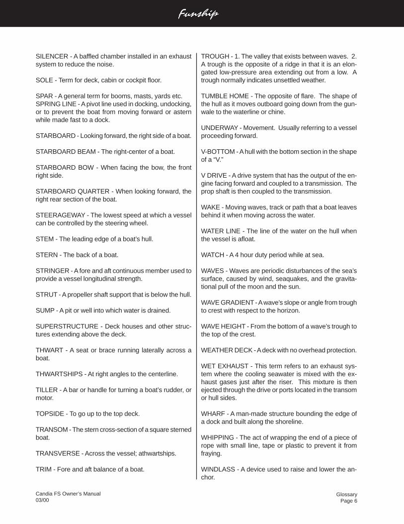
GlossaryPage 6
Candia FS Owner’s Manual03/00
SILENCER - A baffled chamber installed in an exhaustsystem to reduce the noise.
SOLE - Term for deck, cabin or cockpit floor.
SPAR - A general term for booms, masts, yards etc.SPRING LINE - A pivot line used in docking, undocking,or to prevent the boat from moving forward or asternwhile made fast to a dock.
STARBOARD - Looking forward, the right side of a boat.
STARBOARD BEAM - The right-center of a boat.
STARBOARD BOW - When facing the bow, the frontright side.
STARBOARD QUARTER - When looking forward, theright rear section of the boat.
STEERAGEWAY - The lowest speed at which a vesselcan be controlled by the steering wheel.
STEM - The leading edge of a boat’s hull.
STERN - The back of a boat.
STRINGER - A fore and aft continuous member used toprovide a vessel longitudinal strength.
STRUT - A propeller shaft support that is below the hull.
SUMP - A pit or well into which water is drained.
SUPERSTRUCTURE - Deck houses and other struc-tures extending above the deck.
THWART - A seat or brace running laterally across aboat.
THWARTSHIPS - At right angles to the centerline.
TILLER - A bar or handle for turning a boat’s rudder, ormotor.
TOPSIDE - To go up to the top deck.
TRANSOM - The stern cross-section of a square sternedboat.
TRANSVERSE - Across the vessel; athwartships.
TRIM - Fore and aft balance of a boat.
TROUGH - 1. The valley that exists between waves. 2.A trough is the opposite of a ridge in that it is an elon-gated low-pressure area extending out from a low. Atrough normally indicates unsettled weather.
TUMBLE HOME - The opposite of flare. The shape ofthe hull as it moves outboard going down from the gun-wale to the waterline or chine.
UNDERWAY - Movement. Usually referring to a vesselproceeding forward.
V-BOTTOM - A hull with the bottom section in the shapeof a “V.”
V DRIVE - A drive system that has the output of the en-gine facing forward and coupled to a transmission. Theprop shaft is then coupled to the transmission.
WAKE - Moving waves, track or path that a boat leavesbehind it when moving across the water.
WATER LINE - The line of the water on the hull whenthe vessel is afloat.
WATCH - A 4 hour duty period while at sea.
WAVES - Waves are periodic disturbances of the sea’ssurface, caused by wind, seaquakes, and the gravita-tional pull of the moon and the sun.
WAVE GRADIENT - A wave’s slope or angle from troughto crest with respect to the horizon.
WAVE HEIGHT - From the bottom of a wave’s trough tothe top of the crest.
WEATHER DECK - A deck with no overhead protection.
WET EXHAUST - This term refers to an exhaust sys-tem where the cooling seawater is mixed with the ex-haust gases just after the riser. This mixture is thenejected through the drive or ports located in the transomor hull sides.
WHARF - A man-made structure bounding the edge ofa dock and built along the shoreline.
WHIPPING - The act of wrapping the end of a piece ofrope with small line, tape or plastic to prevent it fromfraying.
WINDLASS - A device used to raise and lower the an-chor.

GlossaryPage 7
Candia FS Owner’s Manual03/00
WINDWARD - Toward the direction from which the windis coming.
YAW - 1. To swing off course, as when due to the impactof a following or quartering sea. 2. Any motion about avertical axis.
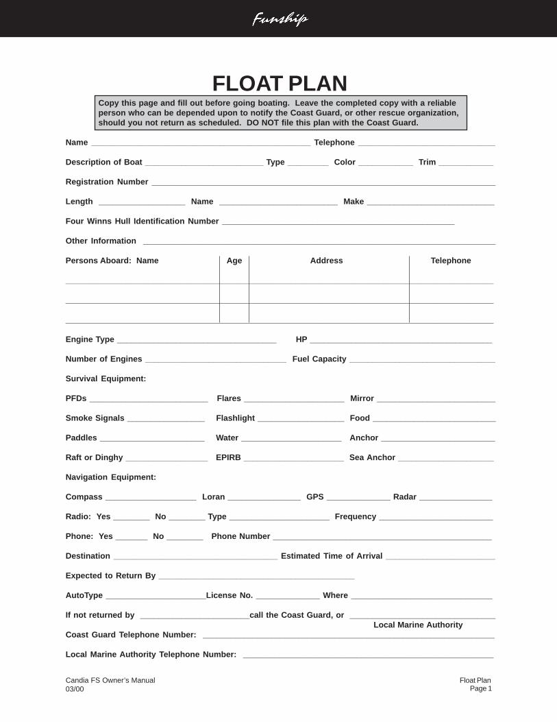
Float PlanPage 1
Candia FS Owner’s Manual03/00
FLOAT PLANCopy this page and fill out before going boating. Leave the completed copy with a reliableperson who can be depended upon to notify the Coast Guard, or other rescue organization,should you not return as scheduled. DO NOT file this plan with the Coast Guard.
Name ________________________________________________ Telephone ______________________________
Description of Boat __________________________ Type _________ Color ____________ Trim ____________
Registration Number ___________________________________________________________________________
Length ___________________ Name __________________________ Make ____________________________
Four Winns Hull Identification Number ___________________________________________________
Other Information _____________________________________________________________________________
Persons Aboard: Name Age Address Telephone
_____________________________________________________________________________________________
_____________________________________________________________________________________________
_____________________________________________________________________________________________
Engine Type ___________________________________ HP ________________________________________
Number of Engines _______________________________ Fuel Capacity ________________________________
Survival Equipment:
PFDs __________________________ Flares ______________________ Mirror __________________________
Smoke Signals _________________ Flashlight ___________________ Food ___________________________
Paddles _______________________ Water ______________________ Anchor _________________________
Raft or Dinghy __________________ EPIRB ______________________ Sea Anchor _____________________
Navigation Equipment:
Compass ____________________ Loran ________________ GPS ______________ Radar ________________
Radio: Yes ________ No ________ Type ______________________ Frequency _________________________
Phone: Yes _______ No ________ Phone Number ________________________________________________
Destination ____________________________________ Estimated Time of Arrival ________________________
Expected to Return By ___________________________________________
AutoType ______________________License No. ______________ Where _______________________________
If not returned by ________________________call the Coast Guard, or ________________________________ Local Marine Authority
Coast Guard Telephone Number: ________________________________________________________________
Local Marine Authority Telephone Number: _______________________________________________________

Fuel LogPage 1
Candia FS Owner’s Manual03/00
FUEL LOG
ETADSRUOH
NURLEUF).LAG(
EGNAR)SELIM(
MPR HPM HPG

Fuel LogPage 2
Candia FS Owner’s Manual03/00
FUEL LOG
ETADSRUOH
NURLEUF).LAG(
EGNAR)SELIM(
MPR HPM HPG

Fuel LogPage 3
Candia FS Owner’s Manual03/00
FUEL LOG
ETADSRUOH
NURLEUF).LAG(
EGNAR)SELIM(
MPR HPM HPG

Service LogPage 1
Candia FS Owner’s Manual03/00
SERVICE LOG
ETAD SRUOH DEMROFREPECNANETNIAM

Service LogPage 2
Candia FS Owner’s Manual03/00
SERVICE LOG
ETAD SRUOH DEMROFREPECNANETNIAM

Service LogPage 3
Candia FS Owner’s Manual03/00
SERVICE LOG
ETAD SRUOH DEMROFREPECNANETNIAM
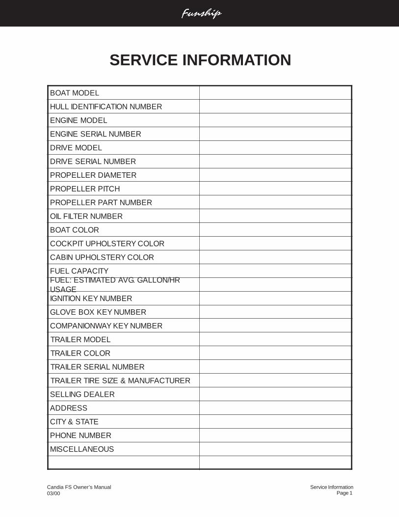
Service InformationPage 1
Candia FS Owner’s Manual03/00
SERVICE INFORMATION
LEDOMTAOB
REBMUNNOITACIFITNEDILLUH
LEDOMENIGNE
REBMUNLAIRESENIGNE
LEDOMEVIRD
REBMUNLAIRESEVIRD
RETEMAIDRELLEPORP
HCTIPRELLEPORP
REBMUNTRAPRELLEPORP
REBMUNRETLIFLIO
ROLOCTAOB
ROLOCYRETSLOHPUTIPKCOC
ROLOCYRETSLOHPUNIBAC
YTICAPACLEUFRH/NOLLAG.GVADETAMITSE:LEUF
EGASUREBMUNYEKNOITINGI
REBMUNYEKXOBEVOLG
REBMUNYEKYAWNOINAPMOC
LEDOMRELIART
ROLOCRELIART
REBMUNLAIRESRELIART
RERUTCAFUNAM&EZISERITRELIART
RELAEDGNILLES
SSERDDA
ETATS&YTIC
REBMUNENOHP
SUOENALLECSIM
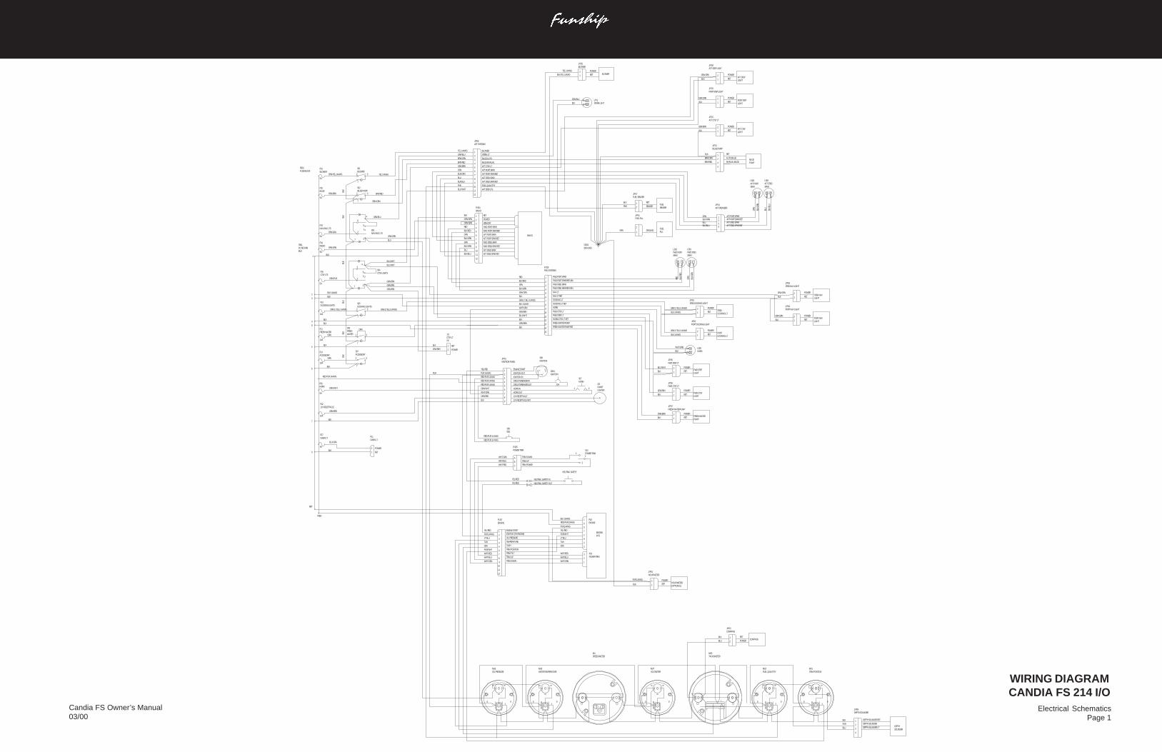
Electrical SchematicsPage 1
Candia FS Owner’s Manual03/00
WIRING DIAGRAMCANDIA FS 214 I/O
WIRING DIAGRAM,214FS IO
P19POWER TRIM
RET
POWER
POWER
RET
BLOWER
HOUR METER(OPTIONAL)
1
2
8
J/P25BLOWER
J/P15HOUR METER
YEL 14AWG
PUR 14AWG
BLK/YEL 14AWG
BLK 1
2
2
3
1
2
3
2
7
5
6
1 P18ENGINE
ENGINE(I/O)
WHT/GRN
WHT/BLU
WHT/RED
GRA
TAN
LT BLU
PUR/WHT
YEL/RED
PUR 14AWG
BLK 10AWG
RED/PUR 10AWG
S09ESS
RED/PUR 14 AWG
RED/PUR 14 AWG
A
B
CWHT/RED
WHT/BLU
WHT/GRN
P/J05POWER TRIM
YEL/RED
YEL/RED
BLK
PNK
J/P17FUEL SENDER
1
2
TRIM DOWN
TRIM UP
NEUTRAL SAFETY
TRIM POWER
FUELSENDER
12
3
S13POWER TRIM
NEUTRAL SAFETY IN
NEUTRAL SAFETY OUT
RET
SENDER
2
7
3
S06FRESHWATER
1
2
3
4
5
6
7
8
9
1
BLK
ORN
ORN/LT BLU 14AWG
ORN/GRN
ORN/GRA
7 3
2
5
4
6
1
ORN/BRN 2
7
3
S02BILGE PUMP
S03NAV/ANC LTS
J/P06AFT SYSTEMS
BLOWER
RED
BLK/RED
BLK/GRN
GRN
GRA/GRN
P/J09FWD SYSTEMS
FWD PORT SPKR
FWD PORT SPKR RETURN
FWD STBD SPKR
FWD STBD SPKR RETURN
NAV LT
NAV LT RET
DOCKING LT
DOCKING LT RET
HORN
10A
F11FRESH WATER
10A
5A
F10DOCKING LIGHTS
5A
F04RADIO
F03NAV/ANC LTS
5A
F02BILGE
FB01FUSE BLOCK
TB01DC RETURNBUS
YEL 14AWG
F01BLOWER
ORN/YEL 14AWG
5A
2
7
3
S01BLOWER
TRIM DOWN
TRIM/TILT
TRIM POSITION
TACH
TEMPERATURE
OIL PRESSURE3
4
5
6
7
9
BLU
BLK
LT BLU
TAN
GRA
PUR/WHT
P/J07ENGINE
2
1
WHT/GRN
ENGINE START
IGNITION (TO ENGINE)
10
12
GRA/BLU 2 STERN LT
BRN/ORN 3 BILGE AUTO
BRN/RED 4 BILGE MANUAL
GRA/BRN 5 AFT CTSY LT
ORN 6 AFT PORT SPKR
BLK/ORN 7 AFT PORT SPKR RET
BLU 8 AFT STBD SPKR
BLK/BLU 9 AFT STBD SPKR RET
PNK 10 FUEL QUANTITY
AFT STEP LTS11
12
2
7
3
S05DOCKING LIGHTS
ORN/PUR
5A
F05CTSY LTS
BLK
BLK
BLK
BLK 14AWG
8 TRIM UP
11
PUR 14AWG
YEL/RED
WHT/RED
WHT/BLU
1
2
1BLK DEPTH SOUNDER RET
2 DEPTH SOUNDER
DEPTH SOUNDER LT3
4
PUR
BLU
J/P09DEPTH SOUNDER
GRA/LT BLU 14AWG
BLK 14AWG
1 ENGINE STARTYEL/RED
PUR 14AWG 2 IGNITION OUT
RED/PUR 14AWG 3 IGNITION IN
RED/PUR 14AWG 4 CIRCUIT BREAKER IN
RED/PUR 14AWG 5 CIRCUIT BREAKER OUT
ORN/WHT 6 HORN IN
WHT/ORN 7 HORN OUT
ORN/RED 8 12V RECEPTACLE
BLK 9 12V RECEPTACLE RET
J/P01 IGNITION PANEL
10 FWD CTSY LT
11 FWD STEP LT
12 HORN/CTSY LT RET
WHT/ORN
GRA/BRN
BLU/WHT
BLK
7 3
2
54
6
1
S04CTSY LIGHTS
BLU/WHT
3BLK
F06HORN
5A
ORN/WHT
ORN/RED
10A
BLK
F14ACCESSORY
10A
ORN
BLK
S07ACCESSORY
3
7
2
GRA/LT BLU 14AWG
BRN/RED
BRN/ORN
YEL 14AWG
GRA/BLU
GRA/GRN
BLU
BLU/WHT
BLU/WHT
GRA/BRN
GRA/BRN
RED/PUR 14AWG
BLK
PUR
F1212V RECEPTACLE
4
6
7
J11CTSY LT2S
1
2
RET
POWERGRA/BRN
BLK
GRA/BRN
5BLK
BLK
BLK
BLK
BLK
ORN/BRN 13 FRESH WATER PUMP
BLK 14 FRESH WATER PUMP RET
15
BLK8
BLU/GRA
5A
BLK
F07CABIN LT
9
P11CABIN LT
2
1
POWER
RET
ORN
1 2
S07HORN
15A
S08IGNITION
CB01IGNITIONI
BS
J22CHARTLIGHTER
1234
AFT PORT SPKRAFT PORT SPKR RETAFT STBD SPKRAFT STBD SPKR RET
ORNBLK/ORNBLUBLK/BLU
J/P14AFT SPEAKERS
J/P01STBD DOCKING LIGHT
BLK 14AWG
GRA/LT BLU 14AWG
J/P02PORT DOCKING LIGHT
J/P03STBD NAV LIGHT
BLK
GRA/GRN
BLK
GRA/GRN
LS05HORN
WHT/ORN
BLK
GRA/BRN
BLK
BLK
BLU/WHT
ORN/BRN
BLK
M01TRIM POSITION
+ S
-
+ S
-
M02FUEL QUANTITY
M03TACHOMETER
M4SPEEDOMETER
M07VOLTMETER
-
+
-
S+
M05WATER TEMPERATLRE
-
S+
M06OIL PRESSURE
ORN/GRN
ORN/GRN
RED
BLK/RED
ORN
BLK/GRN
BLK/ORN
GRN
BLU
BLK/BLU
BLK
AFT STBD SPKR RET
AFT STBD SPKR
FWD STBD SPKR RET
FWD STBD SPKR
AFT PORT SPKR RET
AFT PORT SPKR
FWD PORT SPKR RET
FWD PORT SPKR
MEMORY
POWER
RET
RADIO
P/J04RADIO
12
11
10
9
8
7
6
5
4
3
2
1
LS01FWD STBDSPKR
LS02FWD PORTSPKR
RED
BLK/
RED
GRN
BLK/
GRN
POWER
RETSTBD NAVLIGHT1
2
POWER
RET1
2PORT NAVLIGHT
J/P04PORT NAV LIGHTPOWER
RET1
2STBD DOCKING LT
GRA/LT BLU 14AWG
BLK 14AWG
POWER
RET1
2PORTDOCKING LT
J/P05FWD STEP LT
J/P06FWD CTSY LT
J/P07FRESH WATER PUMP
POWER
RET1
2FWD STEPLIGHT
POWER
RET1
2FWD CTSYLIGHT
POWER
RET1
2FRESH WATERPUMP
RET
FEED
DEPTHSOUNDER
1
2
J/P03COMPASS
COMPASSPOWER
RET
ORN
BLK/
ORN
BLU
BLK/
BLU
LS03AFT PORT SPKR
LS04AFT STBDSPKR
1
2GRN
J/P41FUEL FILL
GND1ENG GND
BLK
GRA/BLU LT01STERN LGHT
GRA/GRN
BLK
GRA/GRN
BLK
J/P28AFT STEP LIGHT
POWER
RET1
2AFT STEPLIGHT
POWER
RET1
2PORT STEPLIGHT
J/P29PORT STEP LIGHT
GRA/BRN
BLK
POWER
RET1
2AFT CTSYLIGHT
J/P16AFT CTSY LT
FUELFILLGROUND
MANUAL BILGE
AUTO BILGE
RET
BILGEPUMP
J/P21BILGE PUMP
4
2
1
3
BRN/ORN
BLK
BRN/RED
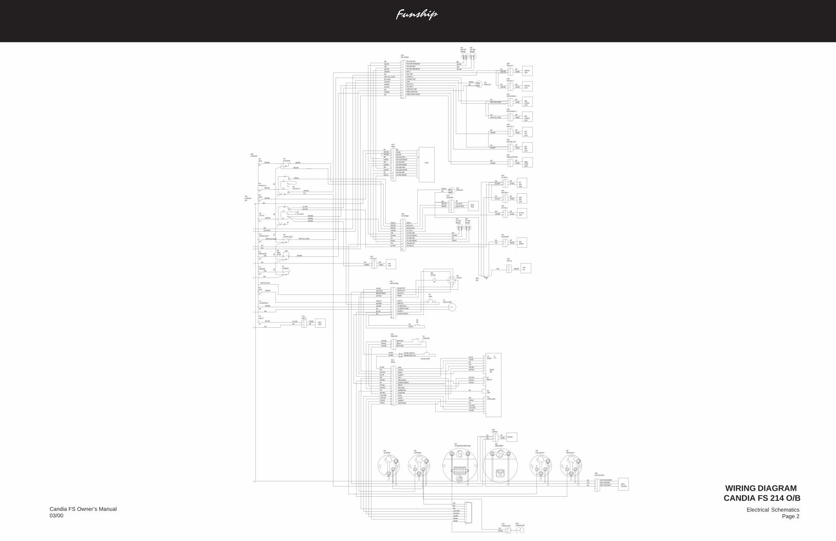
Electrical SchematicsPage 2
Candia FS Owner’s Manual03/00
WIRING DIAGRAM CANDIA FS 214 O/B
BLK
GRA/BRN
J/P11CTSY LIGHT
1
2CTSYLIGHT
RET
POWER
FWDSTEPLIGHT
BLU/WHT
J/P05FWD STBD LIGHT
BLK
POWER
RET
2
1
ORN/BRN
BLKFRESHWATERPUMP
J/P07FRESH WATER PUMP
POWER
RET
2
1
GRA/BRN
BLKFWDCTSY LIGHT
J/P06FWD CTSY LT
POWER
RET
2
1
PORTDOCKINGLIGHT
J/P02PORT DOCKING LT
GRA/LT BLU 14AWG POWER
RET
2
1BLK
GRA/LT BLU 14AWG POWERSTBDDOCKING LIGHT
J/P01STBD DOCKING LT
RET
2
1BLK
LT02STERN LIGHTBLK
GRA/BLU
GRA/GRN POWERPORT NAVLIGHT
J/P04PORT NAV LT
RET
2
1BLK
LS02FWD STBDSPEAKER
LS01FWD PORTSPEAKER
BLK/RED
BLK/GRN
GRN
RED
POWER
RETSTBD NAVLIGHT2
1
J/P03STBD NAV LT
GRA/GRN
BLK
1
2
3
4
5
6
7
8
9
RED
BLK/RED
BLK/GRN
GRN
GRA/GRN
P/J09FWD SYSTEMS
FWD PORT SPKR
FWD PORT SPKR RETURN
FWD STBD SPKR
FWD STBD SPKR RETURN
NAV LT
NAV LT RET
DOCKING LT
DOCKING LT RET
HORN
BLK
GRA/LT BLU 14AWG
BLK 14AWG
10 FWD CTSY LT
11 FWD STEP LT
12 HORN/CTSY LT RET
WHT/ORN
GRA/BRN
BLU/WHT
BLK
ORN/BRN 13 FRESH WATER PUMP
BLK 14 FRESH WATER PUMP RET
15
1
2
3
4
5
6
7
8
9
10
11
12
P/J04RADIO
RADIO
RET
POWER
MEMORY
FWD PORT SPKR
FWD PORT SPKR RET
AFT PORT SPKR
AFT PORT SPKR RET
FWD STBD SPKR
FWD STBD SPKR RET
AFT STBD SPKR
AFT STBD SPKR RET
BLK
BLK/BLU
BLU
GRN
BLK/ORN
BLK/GRN
ORN
BLK/RED
RED
ORN/GRN
ORN/GRN
GRA/BLU
BLK
BRN/RED
BLK
BRN/ORN
LT02STERN LIGHT
3
1
2
4
J/P21BILGE PUMP
BILGEPUMP
RET
AUTO BILGE
MANUAL BILGE
BLK
PNK
J/P17FUEL SENDER
1
2FUELSENDER
RET
SENDER
ORN
BLU
BLK/BLU
BLK/ORN
LS03AFT PORTSPEAKER
LS04AFT STBDSPEAKER
1
J/P06AFT SYSTEMS
GRA/BLU 2 STERN LT
BRN/ORN 3 BILGE AUTO
BRN/RED 4 BILGE MANUAL
GRA/BRN 5 AFT CTSY LT
ORN 6 AFT PORT SPKR
BLK/ORN 7 AFT PORT SPKR RET
BLU 8 AFT STBD SPKR
BLK/BLU 9 AFT STBD SPKR RET
PNK 10 FUEL QUANTITY
AFT STEP LTS11
12
BLU/WHT
POWER
RETHEADLIGHT
2
7
3
S06FRESHWATER
BLK
ORN
ORN/LT BLU 14AWG
ORN/GRN
ORN/GRA
7 3
2
5
4
6
1
ORN/BRN 2
7
3
S02BILGE PUMP
S03NAV/ANC LTS
10A
F11FRESH WATER
10A
5A
F10DOCKING LIGHTS
5A
F04RADIO
F03NAV/ANC LTS
5A
F02BILGE
FB01FUSE BLOCK
TB01DC RETURNBUS
2
7
3
S05DOCKING LIGHTS
ORN/PUR
5A
F05CTSY LTS
BLK
BLK
BLK
1
2
7 3
2
5
4
6
1
S04CTSY LIGHTS
3BLK 14AWG
F06HORN
5A
ORN/WHT
ORN/RED
10A
BLK
F14ACCESSORY
10A
ORN
BLK
S07ACCESSORY
3
7
2
GRA/LT BLU 14AWG
BRN/RED
BRN/ORN
GRA/BLU
GRA/GRN
BLU
BLU/WHT
BLU/WHT
GRA/BRN
GRA/BRN
RED/PUR 14AWG
BLK
F1212V RECEPTACLE
4
6
7
8
GRA/BRN
5BLK
BLK
BLK
BLK
9BLK
ORN/BRN
BLU/GRA
5A
BLK
F07HEAD LT
9
P/J11HEAD LT
2
1BLK
BLU/GRA
ORN
BLK
BLK/YEL
S09ESS
1 2
S07HORN
15A
CB01IGNITION
J22CHART LIGHTER
S08IGNITION
CA
M
B
SMG
8TAN/BLU7TAN/BLK6TAN/GRN5LT BLU/BLK4LT BLU/ORN3GRA2BLK1PUR
M04TACHOMETER/SYSTEM CHECK
68
432
MAGNETO
TAN/BLK
TAN/GRN
LT BLU/BLK
15
14
13
12
11
10
9
8
7
6
5
4
3
2
BLK/YEL
YEL/RED
CHECK ENGINE
OVERHEAT
LOW OIL
WHT/GRN
TAN
PUR
WHT/PUR PRIMER
IGNITION
START1
P/J35ENGINE
LT BLU/ORN
WHT/RED
WHT/BLU
BLK
PUR/WHT
GRA TACH
TRIM POSITIONMAGNETO GROUND
TRIM UP
TRIM DOWN
TEMPERATURE
POWER TRIM
NO OIL
YEL/RED
YEL/RED
21
P/J39WARNING HORN
PUR
TAN/BLU
WH01WARNING HORN
TAN R01TEMP
6
5
4
3
2
1P26SYSTEM CHECK
TAN/GRN
LT BLU/ORN
LT BLU/BLK
BLK
GRA
TAN/BLK
7
3
2
1
6
5
4
3
2
1
P19TRIM/TILT
J18ENGINE
ENGINE(OB)
PUR/WHT
WHT/BLU
WHT/PUR
WHT/RED
PUR
BLK
WHT/GRN
BLK/YEL
YEL/RED
+
-
SI
M01TRIM POSITION
+
-
SI
M02FUEL QUANTITY
+
-
SI
M05WATER TEMP
+
-
I
- +
M03SPEEDOMETER
M06VOLTMETER
NEUTRAL SAFETY OUT
NEUTRAL SAFETY IN
S13POWER TRIM
3
21
TRIM POWER
NEUTRAL SAFETY
TRIM UP
TRIM DOWN
P/J05POWER TRIM
WHT/GRN
WHT/BLU
WHT/RED C
B
A
1ENGINE STARTYEL/RED
PUR 14AWG 2IGNITION OUT
RED/PUR 14AWG 3IGNITION IN
WHT/PUR 4PRIMER
5ORN/WHT 6
HORN IN
WHT/ORN 7HORN OUT
ORN/RED 812V RECEPTACLE
BLK 912V RECEPTACLE RET
J/P01 IGNITION PANEL
BLK/YEL 10MAGNETO
BLK 11MAGNETO GROUND
12
1BLK DEPTH SOUNDER RET
2 DEPTH SOUNDER
DEPTH SOUNDER LT3
4
PUR
BLU
J/P09DEPTH SOUNDER
DEPTHSOUNDER
BLU
BLK 1
2
J/P03COMPASS
COMPASSPOWER
RET
POWER
RETAFT CTSYLIGHT2
1
J/P16AFT CTSY LT
GRA/BRN
BLK
POWER
RETPORTSTEP LIGHT
2
1
J/P41PORT STEP LT
BLU/WHT
BLK
POWER
RETAFTSTEPLIGHT
2
1
J/P40AFT STEP LT
BLU/WHT
BLK
1
2GRN
J/P41FUEL FILL
GND1GND
FUELFILLGROUND
WIRING DIAGRAM,2142FS OB
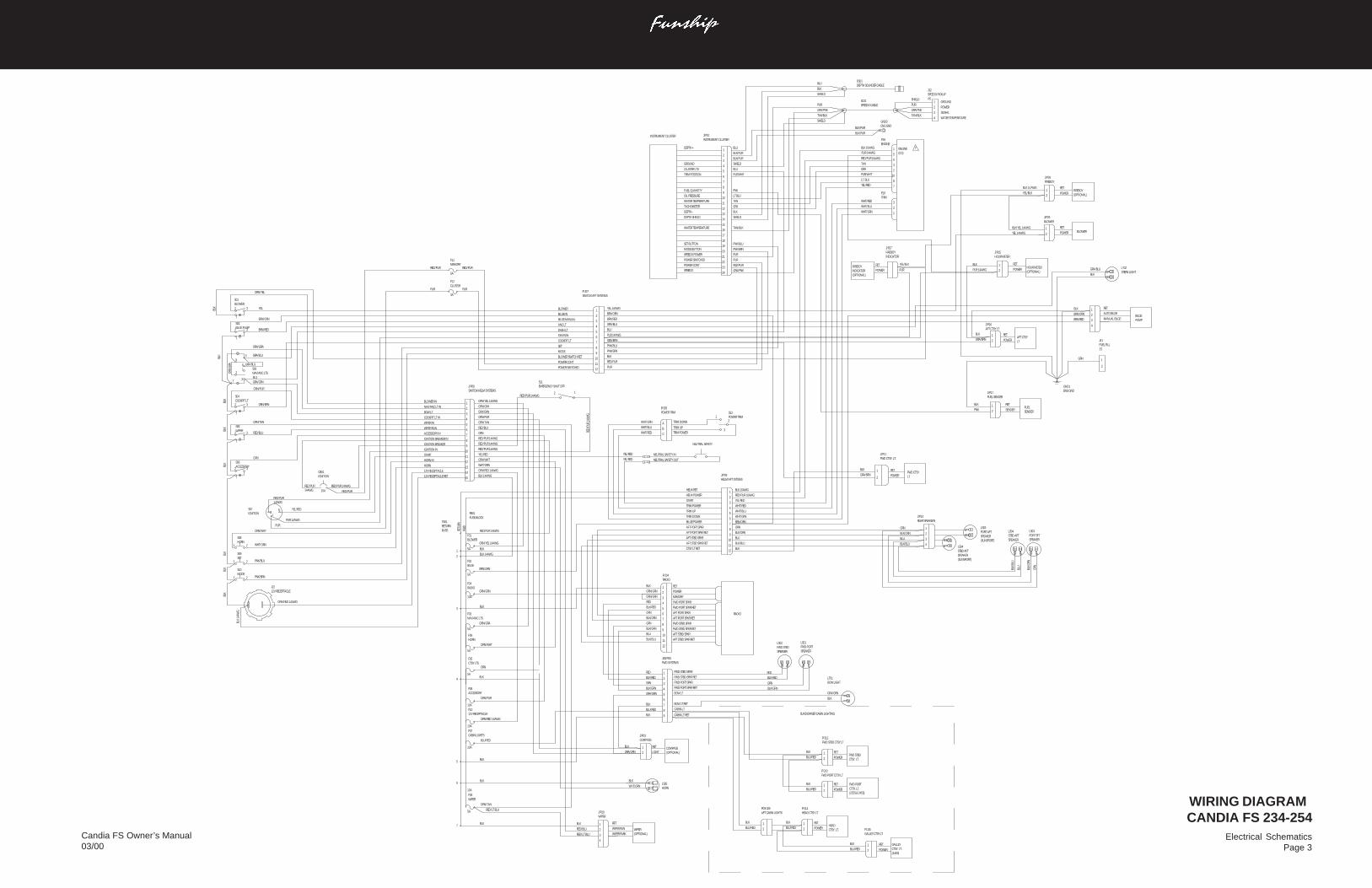
Electrical SchematicsPage 3
Candia FS Owner’s Manual03/00
BLK/PUR
BLK/PUR
BLK/PUR
BLK/PURENG GNDGND3SHIELD
TAN/BLKWATER TEMPERATURE
PURSPEEDO POWER
TAN/BLK
1
2
3
4
WIPERJ/P10
(OPTIONAL)WIPER
RET
WIPER RUN
WIPER PARK
INSTRUMENT CLUSTERJ/P01
TRIMP19
PUR
BLK
BRN/RED
BLU
ORN
BLK/ORN
BLK/BLU
GRA/BLU
BLK
BLK/
BLU
BLK/
ORN
ORN
BLU
BLK
BRN/ORN
BLK
PNK
SPEAKERSTBD AFTLS04
SPEAKERPORT SFTLS03
ENG GNDGND1
2
1GRN
2SFUEL FILLJ41
RED/PUR
HELM/AFT SYTEMSJ/P09
1
2
3
4
5
6
7
8
9
10
11
12
BLK/ORN
BLU
ORN
BRN/ORN
WHT/GRN
WHT/BLU
WHT/RED
YEL/RED
RED/PUR 10AWG
BLK 10AWG
CTSY LT RET
HELM RET
AFT STBD SPKR
AFT STBD SPKR RET
AFT PORT SPKR RET
AFT PORT SPKR
TRIM DOWN
TRIM UP
TRIM POWER
START
HELM POWER
BILGE POWER
SWITCH/AFT SYSTEMSP/J07
COCKPIT LT
BILGE IN
BILGE MANUAL
ANC LT
DASH LT
IGNITION
SET
MODE
POWER CONT
BLOWER SWITCH RET
BLOWER
POWER SWITCHED
YEL 14AWG
BRN/ORN
BRN/RED
GRA/BLU
BLU
PUR 14AWG
GRA/BRN
PNK/BLU
BLK
PNK/BRN
12
11
10
9
8
7
6
5
4
3
2
1
GRA/PNK
RED/PUR
PUR
PNK/BRN
PNK/BLU
SPEEDO24
23
22
21
20
19
18
17
16
POWER CONT
POWER SWITCHED
MODE BUTTON
SET BUTTON
SHIELD
BLU
PUR/WHT
SHIELD
BLK
LT BLU
PNK
INSTRUMENT CLUSTER
DEPTH + BLU1
2
3GROUND
4CLUSTER LTS
5TRIM POSITION
6
7
8
15
14
13
12
11
10
DEPTH SHIELD
DEPTH -
TACHOMETER GRA
WATER TEMPERATURE TAN
OIL PRESSURE
FUEL QUANTITY9
PUR
YEL/BLK
7
2
3
1
7
8
10
2
3
6
5
1
ENGINEP18
(I/O)ENGINE
WHT/GRN
WHT/BLU
WHT/RED
YEL/RED
LT. BLU
PUR/WHT
GRA
TAN
RED/PUR 10AWG
BLK 10AWG
PUR 14AWG
BLK/BLU
BLU
BLK
SHIELD
DEPTH SOUNDER CABLEDS01
PUR
GRA/PNK
TAN/BLK
SPEEDO CABLESC01
PUR
GRA/PNK
SHIELD1
2
3
4
GROUND
POWER
SIGNAL
WATER TEMPERATURE
4SSPEEDO PICKUPJ12
BLK
BLK
GRA/BRN
PUR 14AWG
BLK/YEL 14AWG
BLK 14 AWG
YEL/BLK
YEL 14AWG
5A
RED/BLU
ORN/TAN
RED/LT BLU
BLK4
RED/PUR 14AWG
RED/
PUR
14AW
G
2BLK 14AWG
9RED/PUR 14AWG
RED/PUR 14AWG
START YEL/RED
HORN IN ORN/WHT
WHT/ORN
BLK 14AWG
10
11
12
13
14
15
8RED/PUR 14AWG
7ORN
6
5
4ORN/PUR
3GRA/GRN
2ORN/GRA
1BLOWER IN ORN/YEL 14AWG
SWITCH/HELM SYSTEMSJ/P06
IGNITION BREAKER
IGNITION IN
HORN
12V RECEPTACLE
IGNITION BREAKER IN
ACCESSORY IN
WIPER RUN
WIPER IN
COCKPIT LT IN
BOW LT
NAV/ANC LT IN
12V RECEPTACLE RET
ORN/GRA
BRN/ORN
ORN/GRN
ORN/GRN
RED
BLK/RED
ORN
BLK/GRN
BLK/ORN
GRN
5A
NAV/ANC LTSF03
5A
BILGEF02
FUSE BLOCKFB01
BLOWERF01
ORN/YEL 14AWG
5A
BLU
BLK/BLU
ORN
5A
CTSY LTSF05
BLK
ORN/WHT
HORNF06
ORN/PUR
10A
ACCESSORYF08
ORN/GRN
10A
RADIOF04
BUSSRETURNTB01
BLK
BLK
BLK
1
3
5
FEED
RETU
RN
RED/PUR 14AWG
12V RECEPTACLEF10
10A
ORN/RED 14AWG
RED
BLK/RED
GRN
BLK/GRN
GRA/GRN
BLK
BLU/RED
BLK
BLU/RED
10A
CABIN LIGHTSF07
BLK
HORNLS05
BLK
WHT/ORN6
ORN/RED 14AWG
BLK
GRA/GRN
5A
ORN/TAN
10A
7BLK
WIPERF09
RED/LT BLU
RED/BLU
BLK
SENDER
RET
CABIN LT RET
CABIN LT
BOW LT RET
BOW LT
FWD PORT SPKR RET
FWD PORT SPKR
FWD STBD SPKR RET
FWD STBD SPKR
POWER
RET
MANUAL BILGE
AUTO BILGE
RET
POWER
RET
POWER
RET
POWER
RET
POWER
RET
POWER
RET
AFT STBD SPKR RET
AFT STBD SPKR
FWD STBD SPKR RET
FWD STBD SPKR
AFT PORT SPKR RET
AFT PORT SPKR
FWD PORT SPKR RET
FWD PORT SPKR
MEMORY
POWER
RET
RET
POWER
RET
POWER
RET
POWER
POWER
RET
LIGHT
RET
NEUTRAL SAFETY OUT
NEUTRAL SAFETY IN
POWER TRIMS13
3
21
SUNDOWNER CABIN LIGHTING
LTAFT CTSY
SENDERFUEL
(SUNSPORT)SPEAKERPORT AFTLS03
(SUNSPORT)SPEAKERSTBD AFTLS04
4
3
2
BLK/GRN
GRN
BLK/RED
RED
PUMPBILGE
RADIO
CTSY. LT.HEAD
(245S)CTSY. LT.GALLEY
(225S & 245S)CTSY. LT.FWD PORT
CTSY. LT.FWD STBD
LTFWD CTSY
(OPTIONAL)INDICATORFIREBOY
(OPTIONAL)FIREBOY
BLOWER
(OPTIONAL)HOUR METER
1
2
(OPTIONAL)COMPASS
TRIM POWER
NEUTRAL SAFETY
TRIM UP
TRIM DOWN
EMERGENCY SHUT OFFS11
2 1
BLU/RED
BLK
AFT CABIN LIGHTSP09/J09
2
1
BLU/RED
BLK
GALLEY CTSY LTP/J15
2
1
BLU/RED
BLK
HEAD CTSY LTP/J14
2
1
BLU/RED
BLK
FWD PORT CTSY LTP/J13
2
1
BLU/RED
BLK
FWD STBD CTSY LTP/J12
2
1
BLK
GRA/GRN
BOW LIGHTLT01
SPEAKERFWD PORTLS01
SPEAKERFWD STBDLS02
INDICATORFIREBOYJ/P27
FIREBOYJ/P26
2
1
BLOWERJ/P25
HOUR METERJ/P15
1
2
1
REAR SPEAKERSJ/P14
4
2
1
3
STERN LIGHTLT02
2
1
FUEL SENDERJ/P17
BLK
GRA/BRN1
2
AFT CTSY LTJ/P16
YEL/RED
YEL/RED
POWER TRIMP/J05
WHT/GRN
WHT/BLU
WHT/RED
2
1
COMPASSJ/P03
C
B
A
1
2
FWD CTSY. LT.J/P11
FWD SYSTEMSJ08/P08
RADIOP/J04
12
11
10
9
8
7
6
5
4
3
2
1
9
8
7
6
5
4
3
2
1
PUR PUR
3A
CLUSTERF12
RED/PUR
RED/PUR
PUR 14AWG
RED/PUR
5A
MEMORYF11
ORN/RED 14AWG
BLK
14AW
G
BLK
BLK
BLK
ORN/
GRA GRA/BLU
BLUGRA/GRN
GRA/BLU
ORN/GRA
PNK/BRN
PNK/BLU
ORN/WHT
WHT/ORN
ORN
RED/BLU
ORN/TAN
GRN/BRN
ORN/PUR
BRN/RED
BRN/ORN
YEL
ORN/YEL
12V RECEPTACLEJ22
21MODES10
21SETS09
21HORNS08
ACCESSORYS06
BLK
3
7
2
WIPERS05
BLK
3
7
2
BLK COCKPIT LT
S04
3
7
2
PUR
YEL/RED
14AWGRED/PUR
SB
I
IGNITIONCB01
IGNITIONS07
14AWGRED/PUR RED/PUR 14AWG
15A
BLK
BLOWERS01
3
7
2
BLK
NAV/ANC LTSS03
BILGE PUMPS02
3
7
2
16
45
2
37
WIRING DIAGRAM CANDIA FS 234-254