Embed Size (px)
Citation preview
UserManual
DirectCommunicationModule
(Cat. No. 1747-DCM)
Allen-Bradley
Solid state equipment has operational characteristics differing from those ofelectromechanical equipment. “Safety Guidelines for the Application,Installation and Maintenance of Solid State Controls” (Publication SGI-1.1)describes some important differences between solid state equipment andhard-wired electromechanical devices. Because of this difference, and alsobecause of the wide variety of uses for solid state equipment, all personsresponsible for applying this equipment must satisfy themselves that eachintended application of this equipment is acceptable.
In no event will the Allen-Bradley Company be responsible or liable forindirect or consequential damages resulting from the use or application ofthis equipment.
The examples and diagrams in this manual are included solely for illustrativepurposes. Because of the many variables and requirements associated withany particular installation, the Allen-Bradley Company cannot assumeresponsibility or liability for actual use based on the examples and diagrams.
No patent liability is assumed by Allen-Bradley Company with respect to useof information, circuits, equipment, or software described in this manual.
Reproduction of the contents of this manual, in whole or in part, withoutwritten permission of the Allen-Bradley Company is prohibited.
Throughout this manual we use notes to make you aware of safetyconsiderations.
!ATTENTION: Identifies information about practices orcircumstances that can lead to personal injury or death, propertydamage, or economic loss.
Attentions help you:
• identify a hazard• avoid the hazard• recognize the consequences
Important: Identifies information that is especially important for successfulapplication and understanding of the product.
PLC, PLC-2, PLC-3, and PLC-5 are registered trademarks of Allen-Bradley Company, Inc.SLC, SLC 500, Dataliner, PanelView, RediPANEL, PLC-5/11, PLC-5/15, PLC-5/20, PLC-5/12,PLC-5/25, PLC-5/30, PLC-5/40, PLC-5/60 are trademarks of Allen-Bradley Company, Inc.IBM is a registered trademark of International Business Machines, Incorporated.
Important User Information
Summary of Changes
Summary of Changes
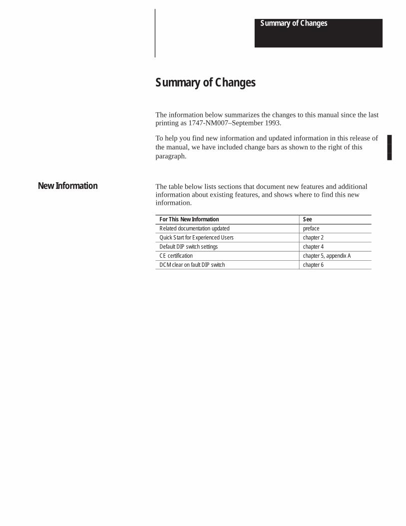
The information below summarizes the changes to this manual since the lastprinting as 1747-NM007–September 1993.
To help you find new information and updated information in this release ofthe manual, we have included change bars as shown to the right of thisparagraph.
The table below lists sections that document new features and additionalinformation about existing features, and shows where to find this newinformation.
For This New Information See
Related documentation updated preface
Quick Start for Experienced Users chapter 2
Default DIP switch settings chapter 4
CE certification chapter 5, appendix A
DCM clear on fault DIP switch chapter 6
New Information

Direct Communication ModuleUser Manual
Table of Contents
i
PrefaceWho Should Use this Manual P–1. . . . . . . . . . . . . . . . . . . . . . . . . . . . . . . . . . . Purpose of this Manual P–1. . . . . . . . . . . . . . . . . . . . . . . . . . . . . . . . . . . . . . . .
Contents of this Manual P–2. . . . . . . . . . . . . . . . . . . . . . . . . . . . . . . . . . . . Related Documentation P–2. . . . . . . . . . . . . . . . . . . . . . . . . . . . . . . . . . . .
Terms and Abbreviations P–4. . . . . . . . . . . . . . . . . . . . . . . . . . . . . . . . . . . . . . Common Techniques Used in this Manual P–5. . . . . . . . . . . . . . . . . . . . . . . . . . Allen-Bradley Support P–5. . . . . . . . . . . . . . . . . . . . . . . . . . . . . . . . . . . . . . . .
Local Product Support P–5. . . . . . . . . . . . . . . . . . . . . . . . . . . . . . . . . . . . . Technical Product Assistance P–5. . . . . . . . . . . . . . . . . . . . . . . . . . . . . . . . Your Questions or Comments on this Manual P–5. . . . . . . . . . . . . . . . . . . . .
Chapter 1Hardware Overview 1–1. . . . . . . . . . . . . . . . . . . . . . . . . . . . . . . . . . . . . . . . . . System Overview 1–2. . . . . . . . . . . . . . . . . . . . . . . . . . . . . . . . . . . . . . . . . . .
What Is a Remote I/O Adapter? 1–2. . . . . . . . . . . . . . . . . . . . . . . . . . . . . . Extended Node Capability 1–4. . . . . . . . . . . . . . . . . . . . . . . . . . . . . . . . . .
Scanner Image Division 1–4. . . . . . . . . . . . . . . . . . . . . . . . . . . . . . . . . . . . . . . Scanner Image Division Configuration Example 1–5. . . . . . . . . . . . . . . . . . .
Data Exchange Between RIO Scanners and the DCM 1–6. . . . . . . . . . . . . . . . . What Is the Status Word? 1–6. . . . . . . . . . . . . . . . . . . . . . . . . . . . . . . . . . .
Chapter 2Required Tools and Equipment 2–1. . . . . . . . . . . . . . . . . . . . . . . . . . . . . . . . . . Procedures 2–2. . . . . . . . . . . . . . . . . . . . . . . . . . . . . . . . . . . . . . . . . . . . . . . .
Chapter 3Addressing Ladder Logic Instructions 3–1. . . . . . . . . . . . . . . . . . . . . . . . . . . . .
PLC/Scanner Addresses 3–2. . . . . . . . . . . . . . . . . . . . . . . . . . . . . . . . . . . SLC Addresses 3–3. . . . . . . . . . . . . . . . . . . . . . . . . . . . . . . . . . . . . . . . . . I/O Image Tables 3–4. . . . . . . . . . . . . . . . . . . . . . . . . . . . . . . . . . . . . . . . .
PLC to DCM/SLC 3–4. . . . . . . . . . . . . . . . . . . . . . . . . . . . . . . . . . . . . . DCM/SLC to PLC 3–4. . . . . . . . . . . . . . . . . . . . . . . . . . . . . . . . . . . . . .
Image Mapping 3–5. . . . . . . . . . . . . . . . . . . . . . . . . . . . . . . . . . . . . . . . . . . . .
Chapter 4DIP Switches 4–1. . . . . . . . . . . . . . . . . . . . . . . . . . . . . . . . . . . . . . . . . . . . . . . DIP Switch 1 Settings 4–2. . . . . . . . . . . . . . . . . . . . . . . . . . . . . . . . . . . . . . . . .
Starting I/O Group Number (SW1-7 and SW1-8) 4–2. . . . . . . . . . . . . . . . . . . Rack Address (SW1-1 through SW1-6) 4–3. . . . . . . . . . . . . . . . . . . . . . . . .
DIP Switch 2 Settings 4–6. . . . . . . . . . . . . . . . . . . . . . . . . . . . . . . . . . . . . . . . . Rack Size (SW2-5 and SW2-6)) 4–6. . . . . . . . . . . . . . . . . . . . . . . . . . . . . . Last Rack (SW2-4) 4–6. . . . . . . . . . . . . . . . . . . . . . . . . . . . . . . . . . . . . . . Clear On Fault (SW2-3) 4–7. . . . . . . . . . . . . . . . . . . . . . . . . . . . . . . . . . . . Data Rate (SW2-1 and SW2-2) 4–7. . . . . . . . . . . . . . . . . . . . . . . . . . . . . . .
Overview
Quick Start for Experienced Users
Addressing
Module Configuration
Direct Communication ModuleUser Manual
Table of Contents
ii
Chapter 5Compliance to European Union Directives 5–1. . . . . . . . . . . . . . . . . . . . . . . . . .
EMC Directive 5–1. . . . . . . . . . . . . . . . . . . . . . . . . . . . . . . . . . . . . . . . . . . DCM Installation 5–1. . . . . . . . . . . . . . . . . . . . . . . . . . . . . . . . . . . . . . . . . . . .
Installation 5–2. . . . . . . . . . . . . . . . . . . . . . . . . . . . . . . . . . . . . . . . . . . . . Removal 5–2. . . . . . . . . . . . . . . . . . . . . . . . . . . . . . . . . . . . . . . . . . . . . . .
Network Wiring 5–3. . . . . . . . . . . . . . . . . . . . . . . . . . . . . . . . . . . . . . . . . . . . .
Chapter 6Overview 6–1. . . . . . . . . . . . . . . . . . . . . . . . . . . . . . . . . . . . . . . . . . . . . . . . . Programming Examples 6–2. . . . . . . . . . . . . . . . . . . . . . . . . . . . . . . . . . . . . . .
Physical Input into PLC – Physical Output from SLC 6–2. . . . . . . . . . . . . . . . Physical Input into SLC – Physical Output from PLC 6–3. . . . . . . . . . . . . . . . Physical Input into Both PLC and SLC (Logical AND) –
Physical Output from SLC 6–3. . . . . . . . . . . . . . . . . . . . . . . . . . . . . . . . Physical Input into First SLC – Physical Output from Second SLC 6–4. . . . . .
Status Words 6–5. . . . . . . . . . . . . . . . . . . . . . . . . . . . . . . . . . . . . . . . . . . . . . RIO Scanner Input Status Word Examination (Decimal) 6–5. . . . . . . . . . . . . DCM/SLC Output Status Word Examination (Octal) 6–6. . . . . . . . . . . . . . . .
Applications Using I/O Status Word Bits 6–7. . . . . . . . . . . . . . . . . . . . . . . . . . . . RIO Scanner Status Word 6–7. . . . . . . . . . . . . . . . . . . . . . . . . . . . . . . . . .
Using the Program/Test/Fault Mode Bit 6–7. . . . . . . . . . . . . . . . . . . . . . . DCM/SLC Output Status Word 6–7. . . . . . . . . . . . . . . . . . . . . . . . . . . . . . .
Using the Data Invalid Bit 6–7. . . . . . . . . . . . . . . . . . . . . . . . . . . . . . . . . Using the User Status Flag Bit 6–8. . . . . . . . . . . . . . . . . . . . . . . . . . . . .
RIO Scanner Input Status and DCM/SLC Output Status 6–10. . . . . . . . . . . . . Using the Logical OR Bit 6–10. . . . . . . . . . . . . . . . . . . . . . . . . . . . . . . . .
Chapter 7DCM Status Indicators 7–1. . . . . . . . . . . . . . . . . . . . . . . . . . . . . . . . . . . . . . . . Troubleshooting Using the FAULT LED (Red) 7–1. . . . . . . . . . . . . . . . . . . . . . . . Troubleshooting Using the COMM LED (Green) 7–2. . . . . . . . . . . . . . . . . . . . . .
Chapter 8Basic Example 8–1. . . . . . . . . . . . . . . . . . . . . . . . . . . . . . . . . . . . . . . . . . . . .
1747-SN Module Configuration 8–1. . . . . . . . . . . . . . . . . . . . . . . . . . . . . . . DIP Switch Settings 8–2. . . . . . . . . . . . . . . . . . . . . . . . . . . . . . . . . . . . . . . System Configuration for Rack 1 8–2. . . . . . . . . . . . . . . . . . . . . . . . . . . . . . System Configuration for Rack 2 8–2. . . . . . . . . . . . . . . . . . . . . . . . . . . . . . Image Table Configuration 8–3. . . . . . . . . . . . . . . . . . . . . . . . . . . . . . . . . . Program Listing 8–3. . . . . . . . . . . . . . . . . . . . . . . . . . . . . . . . . . . . . . . . . .
Supplementary Example 8–4. . . . . . . . . . . . . . . . . . . . . . . . . . . . . . . . . . . . . . Module Configuration 8–4. . . . . . . . . . . . . . . . . . . . . . . . . . . . . . . . . . . . . . DIP Switch Settings 8–5. . . . . . . . . . . . . . . . . . . . . . . . . . . . . . . . . . . . . . . System Configuration 8–5. . . . . . . . . . . . . . . . . . . . . . . . . . . . . . . . . . . . . . Image Table Configuration 8–5. . . . . . . . . . . . . . . . . . . . . . . . . . . . . . . . . .
Installation and Wiring
Programming
Troubleshooting
Application Examples
Direct Communication ModuleUser Manual
Table of Contents
iii
Program Listing for 5/01 8–6. . . . . . . . . . . . . . . . . . . . . . . . . . . . . . . . . . . . Program Listing for PLC5/15 8–9. . . . . . . . . . . . . . . . . . . . . . . . . . . . . . . . .
Appendix AElectrical Specifications A–1. . . . . . . . . . . . . . . . . . . . . . . . . . . . . . . . . . . . . . . Environmental Specifications A–1. . . . . . . . . . . . . . . . . . . . . . . . . . . . . . . . . . . Network Specifications A–1. . . . . . . . . . . . . . . . . . . . . . . . . . . . . . . . . . . . . . . . Throughput Timing A–2. . . . . . . . . . . . . . . . . . . . . . . . . . . . . . . . . . . . . . . . . . .
Appendix BDirections B–1. . . . . . . . . . . . . . . . . . . . . . . . . . . . . . . . . . . . . . . . . . . . . . . . . Addressing Review B–1. . . . . . . . . . . . . . . . . . . . . . . . . . . . . . . . . . . . . . . . . .
PLC Addresses B–1. . . . . . . . . . . . . . . . . . . . . . . . . . . . . . . . . . . . . . . . . . SLC Addresses B–1. . . . . . . . . . . . . . . . . . . . . . . . . . . . . . . . . . . . . . . . . .
Specifications
DCM AddressingWorksheet

Preface
P–1
Preface
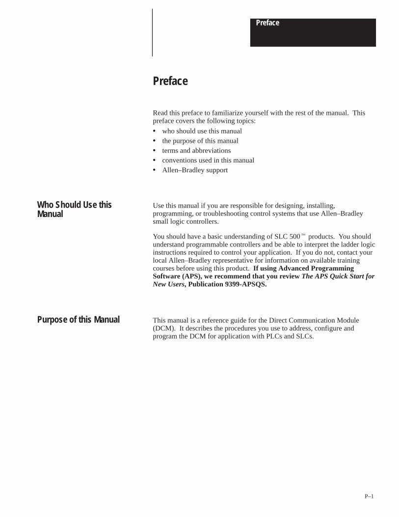
Read this preface to familiarize yourself with the rest of the manual. Thispreface covers the following topics:
• who should use this manual• the purpose of this manual• terms and abbreviations• conventions used in this manual• Allen–Bradley support
Use this manual if you are responsible for designing, installing,programming, or troubleshooting control systems that use Allen–Bradleysmall logic controllers.
You should have a basic understanding of SLC 500� products. You shouldunderstand programmable controllers and be able to interpret the ladder logicinstructions required to control your application. If you do not, contact yourlocal Allen–Bradley representative for information on available trainingcourses before using this product. If using Advanced ProgrammingSoftware (APS), we recommend that you review The APS Quick Start forNew Users, Publication 9399-APSQS.
This manual is a reference guide for the Direct Communication Module(DCM). It describes the procedures you use to address, configure andprogram the DCM for application with PLCs and SLCs.
Who Should Use thisManual
Purpose of this Manual
Preface
P–2
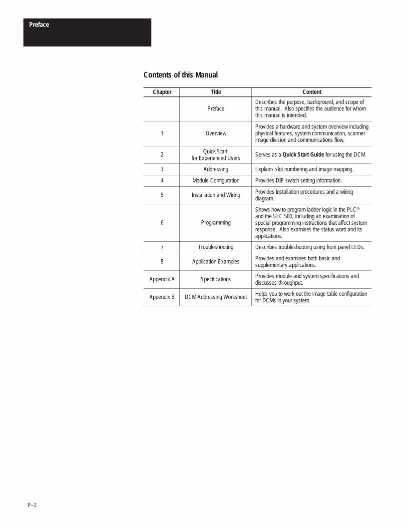
Contents of this Manual
Chapter Title Content
PrefaceDescribes the purpose, background, and scope ofthis manual. Also specifies the audience for whomthis manual is intended.
1 OverviewProvides a hardware and system overview includingphysical features, system communication, scannerimage division and communications flow.
2 Quick Start for Experienced Users
Serves as a Quick Start Guide for using the DCM.
3 Addressing Explains slot numbering and image mapping.
4 Module Configuration Provides DIP switch setting information.
5 Installation and Wiring Provides installation procedures and a wiringdiagram.
6 Programming
Shows how to program ladder logic in the PLC�and the SLC 500, including an examination ofspecial programming instructions that affect systemresponse. Also examines the status word and itsapplications.
7 Troubleshooting Describes troubleshooting using front panel LEDs.
8 Application Examples Provides and examines both basic andsupplementary applications.
Appendix A Specifications Provides module and system specifications anddiscusses throughput.
Appendix B DCM Addressing Worksheet Helps you to work out the image table configurationfor DCMs in your system.
Preface
P–3
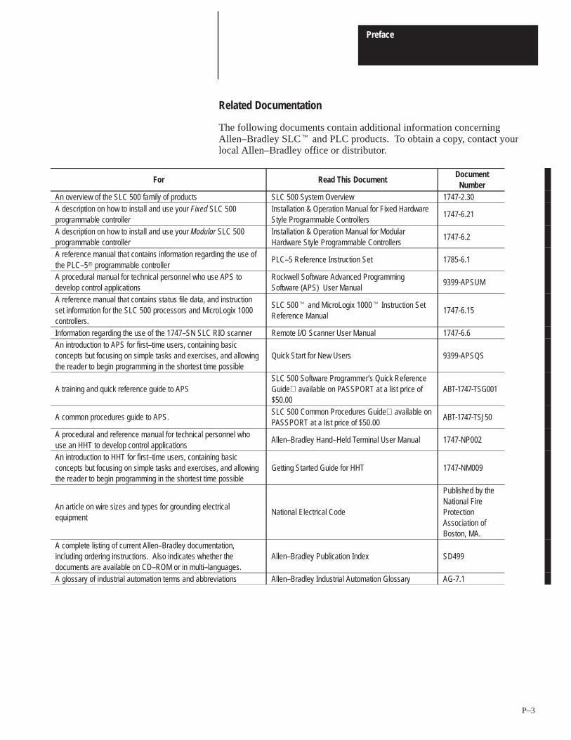
Related Documentation
The following documents contain additional information concerningAllen–Bradley SLC� and PLC products. To obtain a copy, contact yourlocal Allen–Bradley office or distributor.
For Read This DocumentDocument
NumberAn overview of the SLC 500 family of products SLC 500 System Overview 1747-2.30A description on how to install and use your Fixed SLC 500programmable controller
Installation & Operation Manual for Fixed HardwareStyle Programmable Controllers
1747-6.21
A description on how to install and use your Modular SLC 500programmable controller
Installation & Operation Manual for ModularHardware Style Programmable Controllers
1747-6.2
A reference manual that contains information regarding the use ofthe PLC–5� programmable controller
PLC–5 Reference Instruction Set 1785-6.1
A procedural manual for technical personnel who use APS todevelop control applications
Rockwell Software Advanced ProgrammingSoftware (APS) User Manual
9399-APSUM
A reference manual that contains status file data, and instructionset information for the SLC 500 processors and MicroLogix 1000controllers.
SLC 500� and MicroLogix 1000� Instruction SetReference Manual
1747-6.15
Information regarding the use of the 1747–SN SLC RIO scanner Remote I/O Scanner User Manual 1747-6.6An introduction to APS for first–time users, containing basicconcepts but focusing on simple tasks and exercises, and allowingthe reader to begin programming in the shortest time possible
Quick Start for New Users 9399-APSQS
A training and quick reference guide to APSSLC 500 Software Programmer’s Quick ReferenceGuide available on PASSPORT at a list price of$50.00
ABT-1747-TSG001
A common procedures guide to APS.SLC 500 Common Procedures Guide available onPASSPORT at a list price of $50.00
ABT-1747-TSJ50
A procedural and reference manual for technical personnel whouse an HHT to develop control applications
Allen–Bradley Hand–Held Terminal User Manual 1747-NP002
An introduction to HHT for first–time users, containing basicconcepts but focusing on simple tasks and exercises, and allowingthe reader to begin programming in the shortest time possible
Getting Started Guide for HHT 1747-NM009
An article on wire sizes and types for grounding electricalequipment
National Electrical Code
Published by theNational FireProtectionAssociation ofBoston, MA.
A complete listing of current Allen–Bradley documentation,including ordering instructions. Also indicates whether thedocuments are available on CD–ROM or in multi–languages.
Allen–Bradley Publication Index SD499
A glossary of industrial automation terms and abbreviations Allen–Bradley Industrial Automation Glossary AG-7.1
Preface
P–4
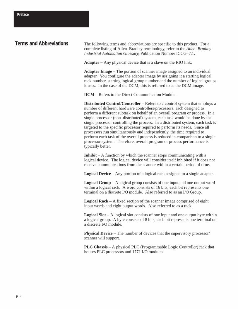
The following terms and abbreviations are specific to this product. For acomplete listing of Allen–Bradley terminology, refer to the Allen–BradleyIndustrial Automation Glossary, Publication Number ICCG–7.1.
Adapter – Any physical device that is a slave on the RIO link.
Adapter Image – The portion of scanner image assigned to an individualadapter. You configure the adapter image by assigning it a starting logicalrack number, starting logical group number and the number of logical groupsit uses. In the case of the DCM, this is referred to as the DCM image.
DCM – Refers to the Direct Communication Module.
Distributed Control/Controller – Refers to a control system that employs anumber of different hardware controllers/processors, each designed toperform a different subtask on behalf of an overall program or process. In asingle processor (non–distributed) system, each task would be done by thesingle processor controlling the process. In a distributed system, each task istargeted to the specific processor required to perform its needs. Since allprocessors run simultaneously and independently, the time required toperform each task of the overall process is reduced in comparison to a singleprocessor system. Therefore, overall program or process performance istypically better.
Inhibit – A function by which the scanner stops communicating with alogical device. The logical device will consider itself inhibited if it does notreceive communications from the scanner within a certain period of time.
Logical Device – Any portion of a logical rack assigned to a single adapter.
Logical Group – A logical group consists of one input and one output wordwithin a logical rack. A word consists of 16 bits, each bit represents oneterminal on a discrete I/O module. Also referred to as an I/O Group.
Logical Rack – A fixed section of the scanner image comprised of eightinput words and eight output words. Also referred to as a rack.
Logical Slot – A logical slot consists of one input and one output byte withina logical group. A byte consists of 8 bits, each bit represents one terminal ona discrete I/O module.
Physical Device – The number of devices that the supervisory processor/scanner will support.
PLC Chassis – A physical PLC (Programmable Logic Controller) rack thathouses PLC processors and 1771 I/O modules.
Terms and Abbreviations
Preface
P–5
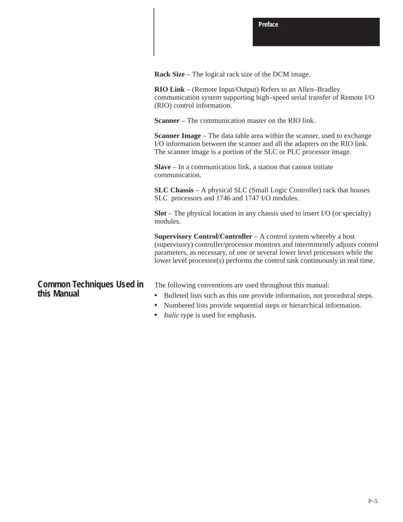
Rack Size – The logical rack size of the DCM image.
RIO Link – (Remote Input/Output) Refers to an Allen–Bradleycommunication system supporting high–speed serial transfer of Remote I/O(RIO) control information.
Scanner – The communication master on the RIO link.
Scanner Image – The data table area within the scanner, used to exchangeI/O information between the scanner and all the adapters on the RIO link.The scanner image is a portion of the SLC or PLC processor image.
Slave – In a communication link, a station that cannot initiatecommunication.
SLC Chassis – A physical SLC (Small Logic Controller) rack that housesSLC processors and 1746 and 1747 I/O modules.
Slot – The physical location in any chassis used to insert I/O (or specialty)modules.
Supervisory Control/Controller – A control system whereby a host(supervisory) controller/processor monitors and intermittently adjusts controlparameters, as necessary, of one or several lower level processors while thelower level processor(s) performs the control task continuously in real time.
The following conventions are used throughout this manual:
• Bulleted lists such as this one provide information, not procedural steps.• Numbered lists provide sequential steps or hierarchical information.• Italic type is used for emphasis.
Common Techniques Used inthis Manual
Preface
P–6
Allen–Bradley offers support services worldwide, with over 75 Sales/SupportOffices, 512 authorized Distributors and 260 authorized Systems Integratorslocated throughout the United States alone, plus Allen–Bradleyrepresentatives in every major country in the world.
Local Product Support
Contact your local Allen–Bradley representative for:
• sales and order support• product technical training• warranty support• support service agreements
Technical Product Assistance
If you need to contact Allen–Bradley for technical assistance, please reviewthe information in the Troubleshooting chapter first. Then call your localAllen–Bradley representative.
Your Questions or Comments on this Manual
If you find a problem with this manual, please notify us of it on the enclosedPublication Problem Report.
If you have any suggestions for how this manual could be made more usefulto you, please contact us at the address below:
Allen–Bradley Company, Inc.
Automation Group
Technical Communication, Dept. 602V, T122
P.O. Box 2086
Milwaukee, WI 53201–2086
Allen–Bradley Support
1Chapter
1–1
Overview
This chapter provides a hardware and system overview including physicalfeatures and connectivity illustrations. It also explains data exchangebetween processors and discusses rack size. Topics include:
• hardware overview• system overview• scanner image division• communications flow
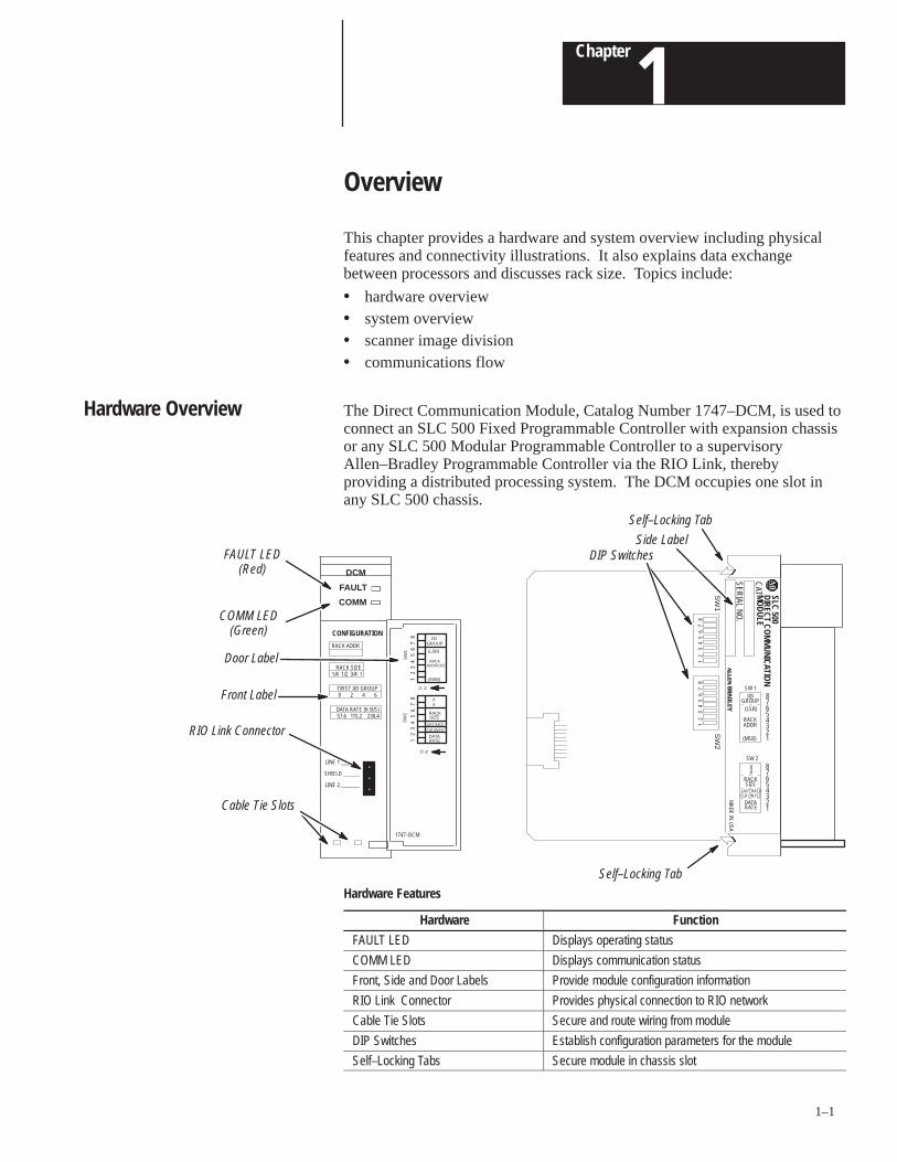
The Direct Communication Module, Catalog Number 1747–DCM, is used toconnect an SLC 500 Fixed Programmable Controller with expansion chassisor any SLC 500 Modular Programmable Controller to a supervisoryAllen–Bradley Programmable Controller via the RIO Link, therebyproviding a distributed processing system. The DCM occupies one slot inany SLC 500 chassis.
Cable Tie Slots
SLC 500
CAT
SERIAL N
O.
DCM
FAULT LED(Red)
Front Label
DIP Switches
RIO Link Connector
Self–Locking Tab
COMM LED(Green)
DIRECT COM
MUNICATIO
N
MAD
E IN U
SA
COMM
FAULT
CONFIGURATION
RACK SIZE1/4 1/2 3/4 1
RACK ADDR
FIRST I/O GROUP0 2 4 6
DATA RATE (K B/S)57.6 115.2 230.4
LINE 1 _______
SHIELD ______
LINE 2 _______
MO
DULE
87654321
87654321
I/OGROUP
(LSB)
(MSB)
XX
RACKSIZE
LAST RACKCLR ON FLT
DATARATE
SW 2
SW 1
Side Label
SW
1S
W2
12
34
56
78
12
34
56
78
RACKADDR
1747–DCM
Door Label
Self–Locking Tab
SW
2S
W1
O N
12
34
56
78
O N
12
34
56
78
I/OGROUP
(LSB)
RACKADDRESS
(MSB)
RACKSIZE
DATARATE
XX
LAST RACK
CLR ON FLT
Hardware Features
Hardware Function
FAULT LED Displays operating status
COMM LED Displays communication status
Front, Side and Door Labels Provide module configuration information
RIO Link Connector Provides physical connection to RIO network
Cable Tie Slots Secure and route wiring from module
DIP Switches Establish configuration parameters for the module
Self–Locking Tabs Secure module in chassis slot
Hardware Overview
Chapter 1Overview
1–2
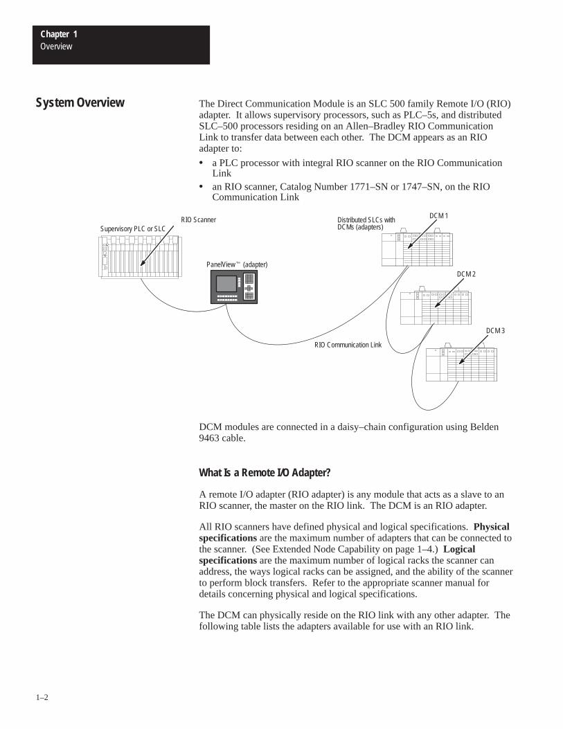
The Direct Communication Module is an SLC 500 family Remote I/O (RIO)adapter. It allows supervisory processors, such as PLC–5s, and distributedSLC–500 processors residing on an Allen–Bradley RIO CommunicationLink to transfer data between each other. The DCM appears as an RIOadapter to:
• a PLC processor with integral RIO scanner on the RIO CommunicationLink
• an RIO scanner, Catalog Number 1771–SN or 1747–SN, on the RIOCommunication Link
RIO Scanner
PanelView� (adapter)
RIO Communication Link
DCM 1
DCM 2
DCM 3
Supervisory PLC or SLCDistributed SLCs withDCMs (adapters)
DCM modules are connected in a daisy–chain configuration using Belden9463 cable.
What Is a Remote I/O Adapter?
A remote I/O adapter (RIO adapter) is any module that acts as a slave to anRIO scanner, the master on the RIO link. The DCM is an RIO adapter.
All RIO scanners have defined physical and logical specifications. Physicalspecifications are the maximum number of adapters that can be connected tothe scanner. (See Extended Node Capability on page 1–4.) Logicalspecifications are the maximum number of logical racks the scanner canaddress, the ways logical racks can be assigned, and the ability of the scannerto perform block transfers. Refer to the appropriate scanner manual fordetails concerning physical and logical specifications.
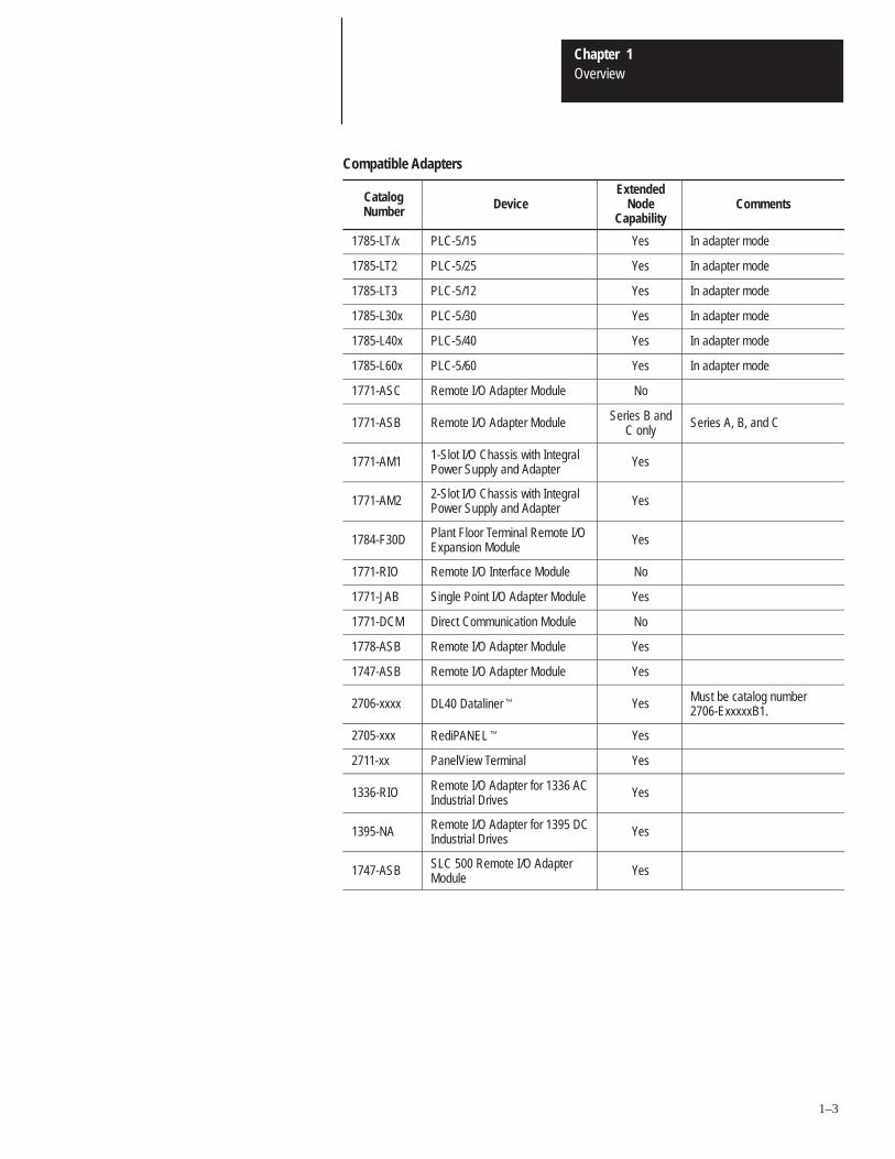
The DCM can physically reside on the RIO link with any other adapter. Thefollowing table lists the adapters available for use with an RIO link.
System Overview
Chapter 1Overview
1–3
Compatible Adapters
CatalogNumber Device
ExtendedNode
CapabilityComments
1785-LT/x PLC-5/15 Yes In adapter mode
1785-LT2 PLC-5/25 Yes In adapter mode
1785-LT3 PLC-5/12 Yes In adapter mode
1785-L30x PLC-5/30 Yes In adapter mode
1785-L40x PLC-5/40 Yes In adapter mode
1785-L60x PLC-5/60 Yes In adapter mode
1771-ASC Remote I/O Adapter Module No
1771-ASB Remote I/O Adapter Module Series B andC only
Series A, B, and C
1771-AM1 1-Slot I/O Chassis with IntegralPower Supply and Adapter
Yes
1771-AM2 2-Slot I/O Chassis with IntegralPower Supply and Adapter
Yes
1784-F30D Plant Floor Terminal Remote I/OExpansion Module
Yes
1771-RIO Remote I/O Interface Module No
1771-JAB Single Point I/O Adapter Module Yes
1771-DCM Direct Communication Module No
1778-ASB Remote I/O Adapter Module Yes
1747-ASB Remote I/O Adapter Module Yes
2706-xxxx DL40 Dataliner� Yes Must be catalog number2706-ExxxxxB1.
2705-xxx RediPANEL� Yes
2711-xx PanelView Terminal Yes
1336-RIO Remote I/O Adapter for 1336 ACIndustrial Drives
Yes
1395-NA Remote I/O Adapter for 1395 DCIndustrial Drives
Yes
1747-ASB SLC 500 Remote I/O AdapterModule
Yes
Chapter 1Overview
1–4
Extended Node Capability
Both scanners and adapters can have extended node capability. Extendednode capability allows you to have up to 32 adapters on the RIO link usingan 82 Ohm termination resistor at both ends of the RIO link for all baudrates.
Extended node capability can only be used if the scanner and all adapters onthe RIO link have extended node capability. The DCM has extended nodecapability.
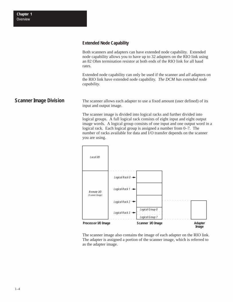
The scanner allows each adapter to use a fixed amount (user defined) of itsinput and output image.
The scanner image is divided into logical racks and further divided intological groups. A full logical rack consists of eight input and eight outputimage words. A logical group consists of one input and one output word in alogical rack. Each logical group is assigned a number from 0–7. Thenumber of racks available for data and I/O transfer depends on the scanneryou are using.
Processor I/O Image Scanner I/O Image AdapterImage
Logical Group 7
Local I/O
Remote I/O(Scanner Image)
Logical Rack 2
Logical Rack 1
Logical Rack 0
Logical Rack 3Logical Group 0
The scanner image also contains the image of each adapter on the RIO link.The adapter is assigned a portion of the scanner image, which is referred toas the adapter image.
Scanner Image Division
Chapter 1Overview
1–5
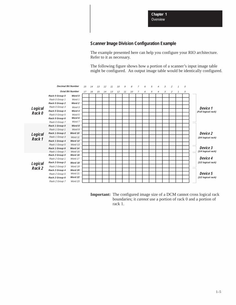
Scanner Image Division Configuration Example
The example presented here can help you configure your RIO architecture.Refer to it as necessary.
The following figure shows how a portion of a scanner’s input image tablemight be configured. An output image table would be identically configured.
Rack 1 Group 2
Rack 1 Group 3
Rack 1 Group 0
Rack 1 Group 1
Rack 1 Group 6
Rack 1 Group 4
Rack 1 Group 5
Rack 0 Group 6
Rack 0 Group 7
Rack 0 Group 4
Rack 0 Group 5
Rack 0 Group 2
Rack 0 Group 3
0123456789101112131415Decimal Bit Number
Word 0
Word 1
Word 2
Word 3
Word 4
Word 7
Word 8
Word 9
Word 10
Word 11
Word 12
Word 13
Word 14
Word 5Word 6
Rack 0 Group 0
Rack 0 Group 1
Rack 2 Group 7
Rack 2 Group 5
Rack 2 Group 6
Rack 2 Group 3
Rack 2 Group 4
Rack 2 Group 1
Rack 2 Group 2
Word 15Word 16
Word 17
Word 18
Word 19
Word 22
Word 23
Word 20Word 21
Rack 1 Group 7Rack 2 Group 0
LogicalRack 0
Device 1
Device 2
Device 3
LogicalRack 1
LogicalRack 2
(Full logical rack)
(3/4 logical rack)
(1/2 logical rack)
Device 5(1/2 logical rack)
Device 4
(1/4 logical rack)
012345671011121314151617Octal Bit Number
Important: The configured image size of a DCM cannot cross logical rackboundaries; it cannot use a portion of rack 0 and a portion ofrack 1.
Chapter 1Overview
1–6
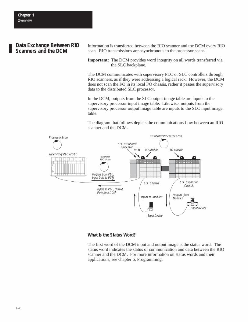
Information is transferred between the RIO scanner and the DCM every RIOscan. RIO transmissions are asynchronous to the processor scans.
Important: The DCM provides word integrity on all words transferred viathe SLC backplane.
The DCM communicates with supervisory PLC or SLC controllers throughRIO scanners, as if they were addressing a logical rack. However, the DCMdoes not scan the I/O in its local I/O chassis, rather it passes the supervisorydata to the distributed SLC processor.
In the DCM, outputs from the SLC output image table are inputs to thesupervisory processor input image table. Likewise, outputs from thesupervisory processor output image table are inputs to the SLC input imagetable.
The diagram that follows depicts the communications flow between an RIOscanner and the DCM.
Output Device
Input Device
Outputs fromModulesInputs to Modules
Outputs from PLC,Input Data to DCM
Inputs to PLC, OutputData from DCM
ScannerRIO Scan
Processor Scan
DCM I/O Module
Distributed Processor Scan
SLC Chassis SLC ExpansionChassis
I/O Module
SLC DistributedProcessor
Supervisory PLC or SLC
What Is the Status Word?
The first word of the DCM input and output image is the status word. Thestatus word indicates the status of communication and data between the RIOscanner and the DCM. For more information on status words and theirapplications, see chapter 6, Programming.
Data Exchange Between RIOScanners and the DCM
2Chapter
2–1
Quick Start for Experienced Users
This chapter helps you to get started using the Direct CommunicationModule (DCM). We base the procedures here on the assumption that youhave a basic understanding of SLC 500 products.
You must:
• understand electronic process control
• be able to interpret the ladder logic instructions for generating theelectronic signals that control your application
Because it is a start-up guide for experienced users, this chapter does notcontain detailed explanations about the procedures listed. It does, however,reference other chapters in this book where you can get more detailedinformation. It also references other documentation that may be helpful ifyou are unfamiliar with programming techniques or system installationrequirements.
If you have any questions, or are unfamiliar with the terms used or conceptspresented in the procedural steps, always read the referenced chapters andother recommended documentation before trying to apply the information.
This chapter:
• tells you what tools and equipment you need
• lists preliminary considerations
• describes when to address, configure and program the module
• explains how to install and wire the module
• discusses system power-up procedures
Have the following tools and equipment ready:
• medium blade screwdriver• (2) 1/2 watt terminating resistors (See chapter 5, Installation and Wiring,
for correct size.)• programming equipment (All programming examples shown in this
manual demonstrate the use of Allen-Bradley’s Advanced ProgrammingSoftware [APS] for personal computers.)
Required Tools andEquipment
Chapter 2Quick Start for Experienced Users
2–2
1. Check the contents of the shipping box. Reference
Unpack the module making sure that the contents include:
• Direct Communication Module (Catalog Number 1747-DCM)
• removable connector (factory-installed on module)
• cable tie
• user manual (Catalog Number 1747-NM007)
–
If the contents are incomplete, call your local Allen-Bradley representative for assistance.
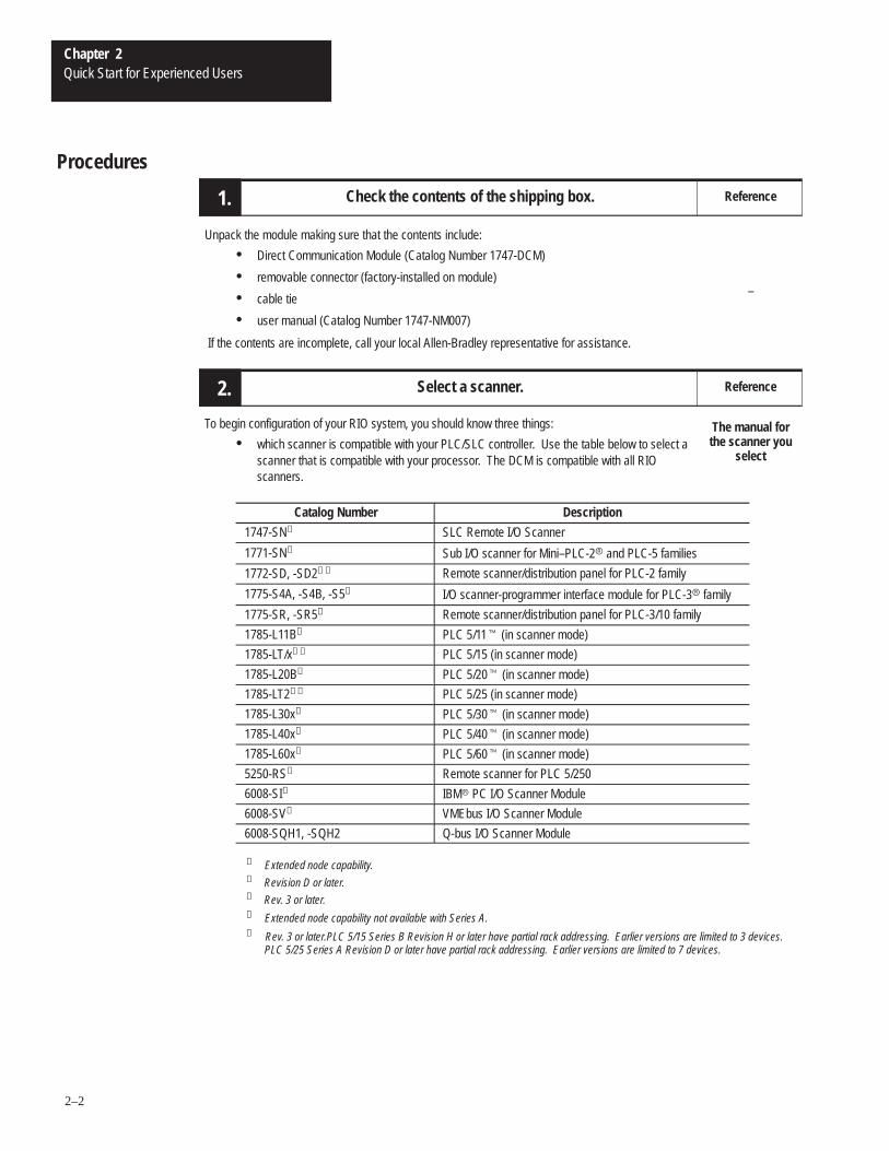
2.2. Select a scanner. Reference
To begin configuration of your RIO system, you should know three things:
• which scanner is compatible with your PLC/SLC controller. Use the table below to select ascanner that is compatible with your processor. The DCM is compatible with all RIO scanners.
The manual forthe scanner you
select
Catalog Number Description
1747-SN➀ SLC Remote I/O Scanner
1771-SN➁ Sub I/O scanner for Mini–PLC-2� and PLC-5 families
1772-SD, -SD2➂➃ Remote scanner/distribution panel for PLC-2 family
1775-S4A, -S4B, -S5➀ I/O scanner-programmer interface module for PLC-3� family
1775-SR, -SR5➀ Remote scanner/distribution panel for PLC-3/10 family
1785-L11B➀ PLC 5/11� (in scanner mode)
1785-LT/x➀➄ PLC 5/15 (in scanner mode)
1785-L20B➀ PLC 5/20� (in scanner mode)
1785-LT2➀➄ PLC 5/25 (in scanner mode)
1785-L30x➀ PLC 5/30� (in scanner mode)
1785-L40x➀ PLC 5/40� (in scanner mode)
1785-L60x➀ PLC 5/60� (in scanner mode)
5250-RS➀ Remote scanner for PLC 5/250
6008-SI➀ IBM� PC I/O Scanner Module
6008-SV➀ VMEbus I/O Scanner Module
6008-SQH1, -SQH2 Q-bus I/O Scanner Module
➀ Extended node capability.➁ Revision D or later.➂ Rev. 3 or later.➃ Extended node capability not available with Series A.➄ Rev. 3 or later.PLC 5/15 Series B Revision H or later have partial rack addressing. Earlier versions are limited to 3 devices.
PLC 5/25 Series A Revision D or later have partial rack addressing. Earlier versions are limited to 7 devices.
Procedures
Chapter 2Quick Start for Experienced Users
2–3
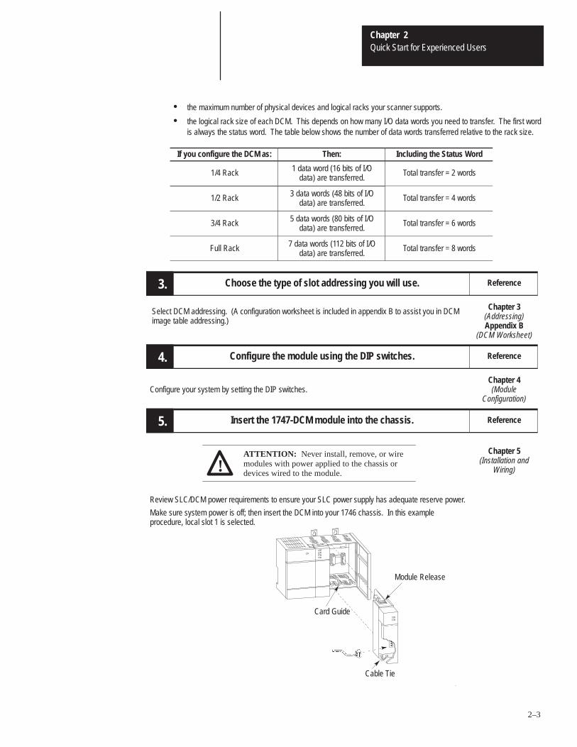
• the maximum number of physical devices and logical racks your scanner supports.
• the logical rack size of each DCM. This depends on how many I/O data words you need to transfer. The first wordis always the status word. The table below shows the number of data words transferred relative to the rack size.
If you configure the DCM as: Then: Including the Status Word
1/4 Rack 1 data word (16 bits of I/Odata) are transferred.
Total transfer = 2 words
1/2 Rack 3 data words (48 bits of I/Odata) are transferred.
Total transfer = 4 words
3/4 Rack 5 data words (80 bits of I/Odata) are transferred.
Total transfer = 6 words
Full Rack 7 data words (112 bits of I/Odata) are transferred.
Total transfer = 8 words
3. Choose the type of slot addressing you will use. Reference
Select DCM addressing. (A configuration worksheet is included in appendix B to assist you in DCMimage table addressing.)
Chapter 3(Addressing)Appendix B
(DCM Worksheet)
4. Configure the module using the DIP switches. Reference
Configure your system by setting the DIP switches.Chapter 4(Module
Configuration)
5. Insert the 1747-DCM module into the chassis. Reference
ATTENTION: Never install, remove, or wiremodules with power applied to the chassis ordevices wired to the module.!
Chapter 5(Installation and
Wiring)
Review SLC/DCM power requirements to ensure your SLC power supply has adequate reserve power.
Make sure system power is off; then insert the DCM into your 1746 chassis. In this exampleprocedure, local slot 1 is selected.
.
.
.
Card Guide
Cable Tie
Module Release
Chapter 2Quick Start for Experienced Users
2–4
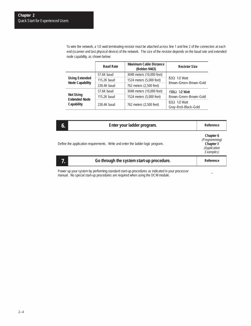
To wire the network, a 1/2 watt terminating resistor must be attached across line 1 and line 2 of the connectors at eachend (scanner and last physical device) of the network. The size of the resistor depends on the baud rate and extendednode capability, as shown below:
Baud RateMaximum Cable Distance
(Belden 9463) Resistor Size
Us n xten e57.6K baud 3048 meters (10,000 feet)
8 � 1Using Extendedo e apab l t
115.2K baud 1524 meters (5,000 feet) 82� 1/2 Wattr Gr r GNode Capability
230.4K baud 762 meters (2,500 feet)Brown–Green–Brown–Gold
ot Us n57.6K baud 3048 meters (10,000 feet) 150� 1/2 Watt
Not Usingxten e o e
115.2K baud 1524 meters (5,000 feet)150� 1/2 WattBrown–Green–Brown–Gold
Extended NodeCapability 230.4K baud 762 meters (2,500 feet)
82� 1/2 WattGray–Red–Black–Gold
6. Enter your ladder program. Reference
Define the application requirements. Write and enter the ladder logic program.
Chapter 6(Programming)
Chapter 8(ApplicationExamples)
7. Go through the system start-up procedure. Reference
Power up your system by performing standard start-up procedures as indicated in your processormanual. No special start-up procedures are required when using the DCM module.
–
3Chapter
3–1
Addressing
This chapter provides general information about how to address supervisoryPLC and distributed SLC ladder logic instructions. It also illustrates imagemapping and provides an example of how a PLC output image is mappedinto an SLC input image.
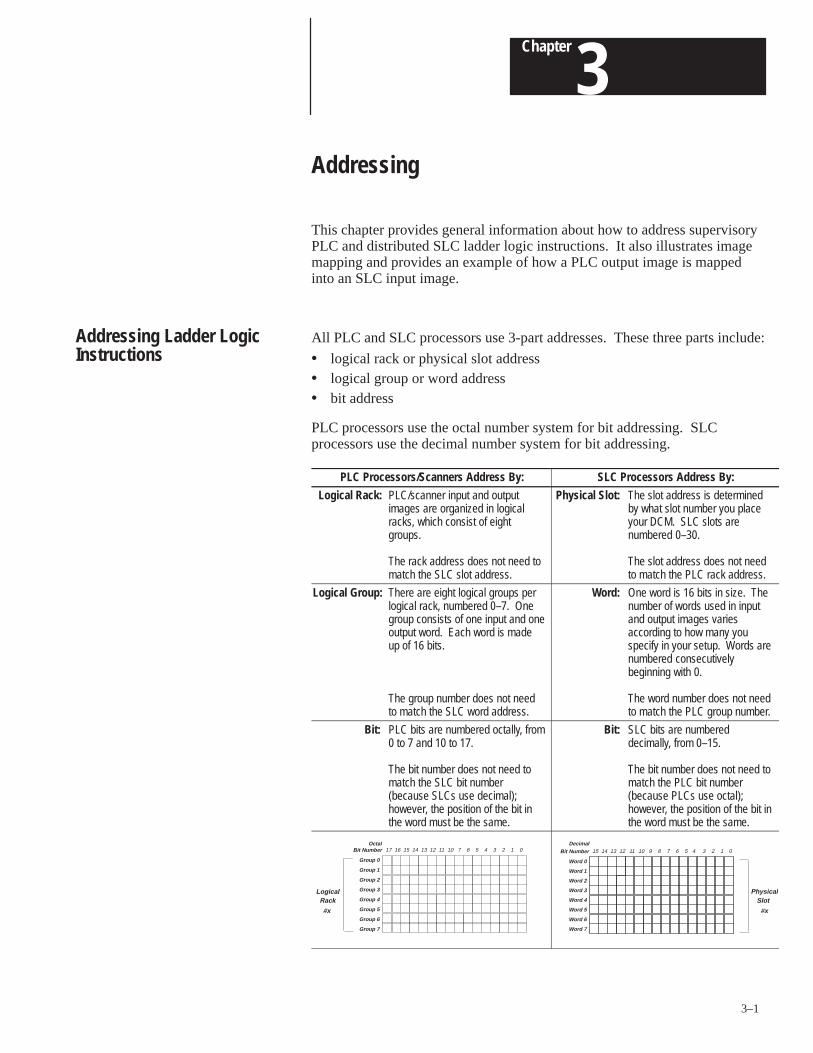
All PLC and SLC processors use 3-part addresses. These three parts include:
• logical rack or physical slot address• logical group or word address• bit address
PLC processors use the octal number system for bit addressing. SLCprocessors use the decimal number system for bit addressing.
PLC Processors/Scanners Address By: SLC Processors Address By:
Logical Rack: PLC/scanner input and outputimages are organized in logicalracks, which consist of eightgroups.
The rack address does not need tomatch the SLC slot address.
Physical Slot: The slot address is determinedby what slot number you placeyour DCM. SLC slots arenumbered 0–30.
The slot address does not needto match the PLC rack address.
Logical Group: There are eight logical groups perlogical rack, numbered 0–7. Onegroup consists of one input and oneoutput word. Each word is madeup of 16 bits.
The group number does not needto match the SLC word address.
Word: One word is 16 bits in size. Thenumber of words used in inputand output images variesaccording to how many youspecify in your setup. Words arenumbered consecutivelybeginning with 0.
The word number does not needto match the PLC group number.
Bit: PLC bits are numbered octally, from0 to 7 and 10 to 17.
The bit number does not need tomatch the SLC bit number(because SLCs use decimal);however, the position of the bit inthe word must be the same.
Bit: SLC bits are numbereddecimally, from 0–15.
The bit number does not need tomatch the PLC bit number(because PLCs use octal);however, the position of the bit inthe word must be the same.
Bit Number 17 16 15 14 13 12 11 10 7 6 5 4 3 2 1 0
Group 0
Group 1
Group 2
Group 3
Group 4
Group 5
Group 6
Group 7
LogicalRack
#x
OctalBit Number 15 14 13 12 11 10 9 8 7 6 5 4 3 2 1 0
Word 0
Word 1
Word 2
Word 3
Word 4
Word 5
Word 6
Word 7
Physica lSlot
#x
Decimal
Addressing Ladder LogicInstructions
Chapter 3Addressing
3–2
PLC/Scanner Addresses
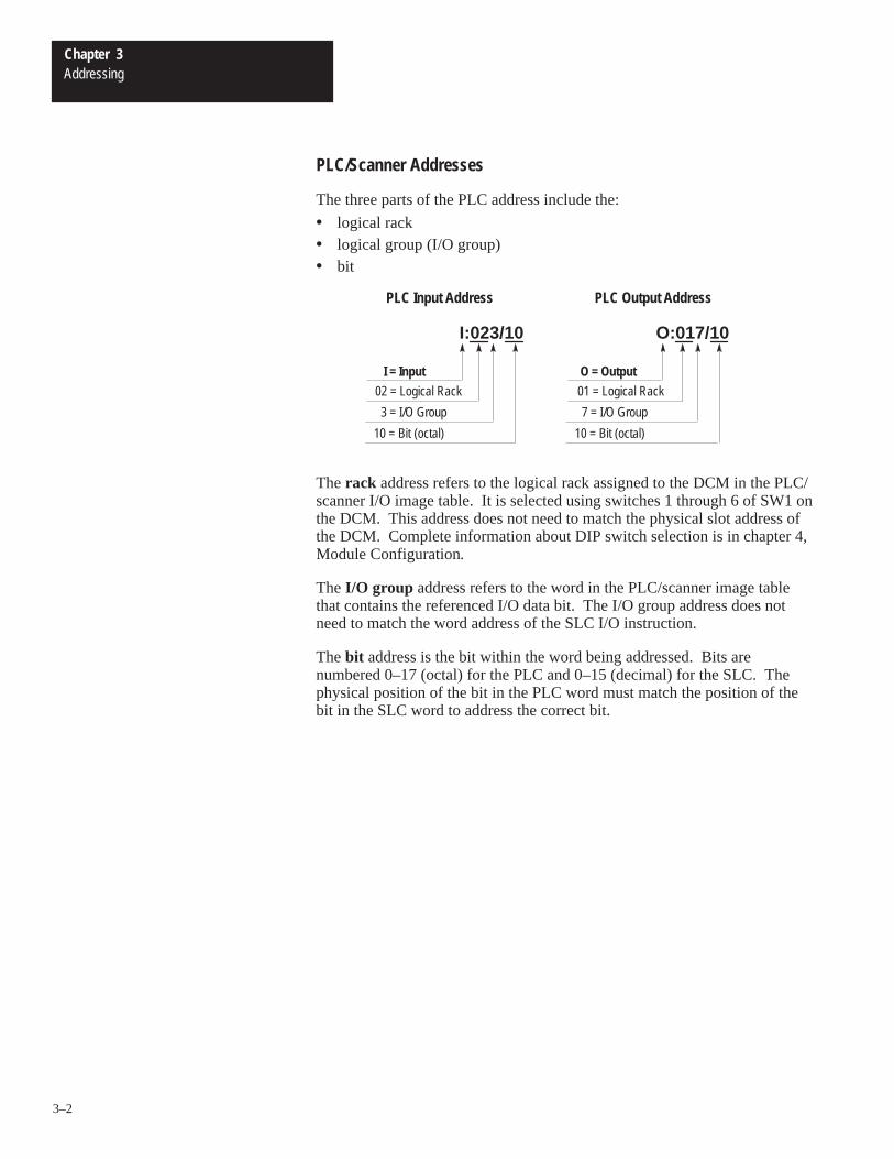
The three parts of the PLC address include the:
• logical rack• logical group (I/O group)• bit
I = Input
O:017/10I:023/10
02 = Logical Rack
3 = I/O Group
10 = Bit (octal)
O = Output
01 = Logical Rack
7 = I/O Group
10 = Bit (octal)
PLC Input Address PLC Output Address
The rack address refers to the logical rack assigned to the DCM in the PLC/scanner I/O image table. It is selected using switches 1 through 6 of SW1 onthe DCM. This address does not need to match the physical slot address ofthe DCM. Complete information about DIP switch selection is in chapter 4,Module Configuration.
The I/O group address refers to the word in the PLC/scanner image tablethat contains the referenced I/O data bit. The I/O group address does notneed to match the word address of the SLC I/O instruction.
The bit address is the bit within the word being addressed. Bits arenumbered 0–17 (octal) for the PLC and 0–15 (decimal) for the SLC. Thephysical position of the bit in the PLC word must match the position of thebit in the SLC word to address the correct bit.
Chapter 3Addressing
3–3
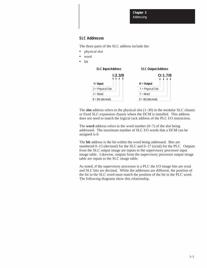
SLC Addresses
The three parts of the SLC address include the:
• physical slot• word• bit
I = Input
O:1.7/8I:2.3/8
2 = Physical Slot
3 = Word
8 = Bit (decimal)
O = Output
1 = Physical Slot
7 = Word
8 = Bit (decimal)
SLC Input Address SLC Output Address
The slot address refers to the physical slot (1–30) in the modular SLC chassisor fixed SLC expansion chassis where the DCM is installed. This addressdoes not need to match the logical rack address of the PLC I/O instruction.
The word address refers to the word number (0–7) of the slot beingaddressed. The maximum number of SLC I/O words that a DCM can beassigned is 8.
The bit address is the bit within the word being addressed. Bits arenumbered 0–15 (decimal) for the SLC and 0–17 (octal) for the PLC. Outputsfrom the SLC output image are inputs to the supervisory processor inputimage table. Likewise, outputs from the supervisory processor output imagetable are inputs to the SLC image table.
As noted, if the supervisory processor is a PLC the I/O image bits are octaland SLC bits are decimal. While the addresses are different, the position ofthe bit in the SLC word must match the position of the bit in the PLC word.The following diagrams show this relationship.
Chapter 3Addressing
3–4
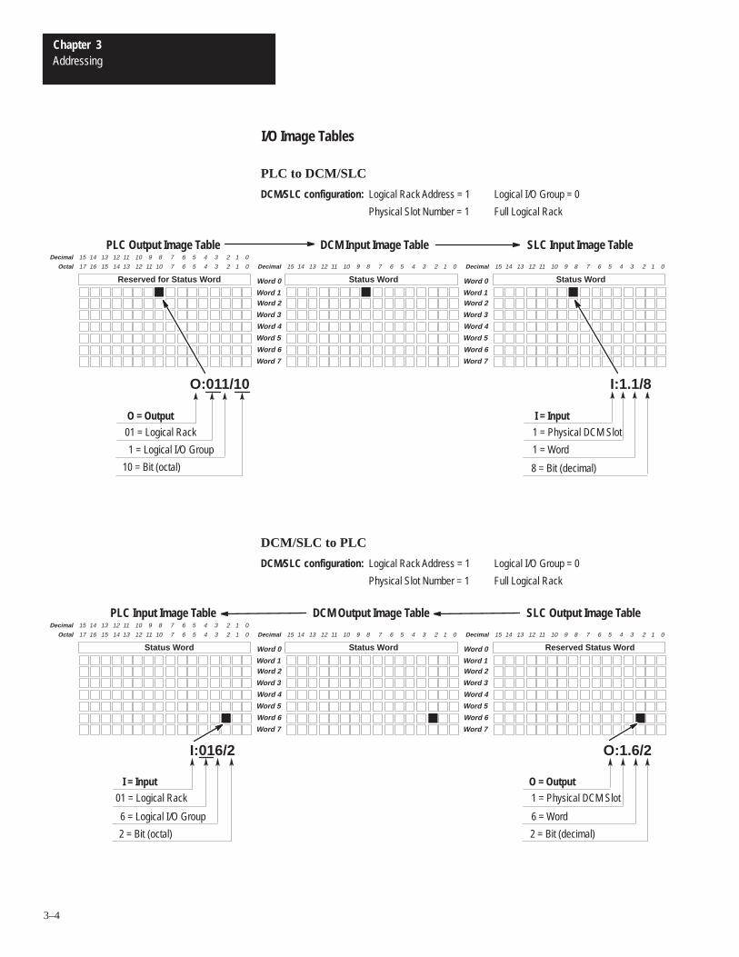
I/O Image Tables
Word 2
Word 3
Word 4
Word 5
Word 6
Word 7
Word 0
Word 1
Reserved for Status W ord
Decimal
Reserved for Status W ord
17 16 15 14 13 12 7 6 5 4 3 2 1 011 10Octal
Word 2
Word 3
Word 4
Word 5
Word 6
Word 7
Word 0
Word 1
Reserved for Status W ordStatus W ord Reserved for Status W ordStatus W ord
15 14 13 12 11 10 7 6 5 4 3 2 1 09 8
Decimal 15 14 13 12 11 10 7 6 5 4 3 2 1 09 8 Decimal 15 14 13 12 11 10 7 6 5 4 3 2 1 09 8
I = Input
I:1.1/8
1 = Physical DCM Slot
1 = Word
8 = Bit (decimal)
SLC Input Image Table
O:011/10
O = Output
01 = Logical Rack
1 = Logical I/O Group
10 = Bit (octal)
PLC Output Image Table DCM Input Image Table
Word 2
Word 3
Word 4
Word 5
Word 6
Word 7
Word 0
Word 1
Reserved for Status W ord
Decimal
Status W ord
17 16 15 14 13 12 7 6 5 4 3 2 1 011 10Octal
Word 2
Word 3
Word 4
Word 5
Word 6
Word 7
Word 0
Word 1
Reserved for Status W ordStatus W ord Reserved for Status W ordReserved Status W ord
15 14 13 12 11 10 7 6 5 4 3 2 1 09 8
Decimal 15 14 13 12 11 10 7 6 5 4 3 2 1 09 8 Decimal 15 14 13 12 11 10 7 6 5 4 3 2 1 09 8
O:1.6/2
SLC Output Image Table
I:016/2
PLC Input Image Table DCM Output Image Table
O = Output
1 = Physical DCM Slot
6 = Word
2 = Bit (decimal)
I = Input
01 = Logical Rack
6 = Logical I/O Group
2 = Bit (octal)
DCM/SLC to PLC
DCM/SLC configuration: Logical Rack Address = 1
Physical Slot Number = 1
Logical I/O Group = 0
Full Logical Rack
PLC to DCM/SLC
DCM/SLC configuration: Logical Rack Address = 1
Physical Slot Number = 1
Logical I/O Group = 0
Full Logical Rack
Chapter 3Addressing
3–5
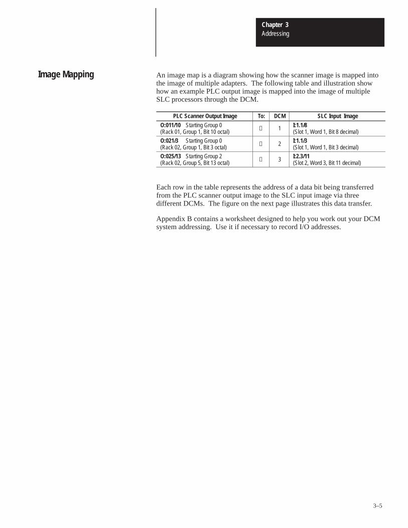
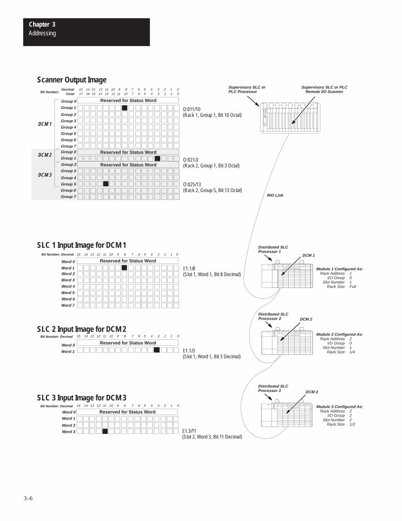
An image map is a diagram showing how the scanner image is mapped intothe image of multiple adapters. The following table and illustration showhow an example PLC output image is mapped into the image of multipleSLC processors through the DCM.
PLC Scanner Output Image To: DCM SLC Input Image
O:011/10 Starting Group 0(Rack 01, Group 1, Bit 10 octal) → 1 I:1.1/8
(Slot 1, Word 1, Bit 8 decimal)
O:021/3 Starting Group 0(Rack 02, Group 1, Bit 3 octal) → 2 I:1.1/3
(Slot 1, Word 1, Bit 3 decimal)
O:025/13 Starting Group 2(Rack 02, Group 5, Bit 13 octal) → 3 I:2.3/11
(Slot 2, Word 3, Bit 11 decimal)
Each row in the table represents the address of a data bit being transferredfrom the PLC scanner output image to the SLC input image via threedifferent DCMs. The figure on the next page illustrates this data transfer.
Appendix B contains a worksheet designed to help you work out your DCMsystem addressing. Use it if necessary to record I/O addresses.
Image Mapping
Chapter 3Addressing
3–6
10 9
Word 2
Word 3
Word 4
Word 5
Word 6
Word 7
Octal 15 14 13 12 11 10 7 6 5 4 3 2 1 0
Group 0
Group 1
Group 0
Group 1
17 16
DCM 1
DCM 2
DCM 3
Module 2 Configured As:Rack Address 2
I/O Group 0Slot Number 1
Rack Size 1/4
Module 1 Configured As:Rack Address 1
I/O Group 0Slot Number 1
Rack Size Full
Module 3 Configured As:Rack Address 2
I/O Group 2Slot Number 2
Rack Size 1/2
Supervisory SLC or PLCRemote I/O Scanner
DCM 1
Word 0
Word 1
Reserved for Status W ord
Group 2
Group 3
Group 4
Group 5
Group 6
Group 7
Group 2
Group 3
Group 4
Group 5
15 14 13 12 11 10 7 6 5 4 3 2 1 09 8
Reserved for Status W ord
Bit Number: Decimal
Word 0
Word 1
15 14 13 12 11 10 7 6 5 4 3 2 1 09 8
Word 0
Word 1
Word 2
Word 3
Bit Number: Decimal 15 14 13 12 11 10 7 6 5 4 3 2 1 09 8
I:1.1/8(Slot 1, Word 1, Bit 8 Decimal)
I:1.1/3(Slot 1, Word 1, Bit 3 Decimal)
O:021/2(Rack 2, Group 1, Bit 3 Octal)
O:011/10(Rack 1, Group 1, Bit 10 Octal)
O:025/13(Rack 2, Group 5, Bit 13 Octal)
I:1.3/11(Slot 2, Word 3, Bit 11 Decimal)
Bit Number: Decimal
Scanner Output Image
SLC 1 Input Image for DCM 1
SLC 2 Input Image for DCM 2
SLC 3 Input Image for DCM 3
Group 6
Group 7
Reserved for Status W ord
Reserved for Status W ord
Reserved for Status W ord
Reserved for Status W ord
Reserved for Status W ord
DCM 2
DCM 3
Supervisory SLC orPLC Processor
RIO Link
Distributed SLCProcessor 2
Distributed SLCProcessor 1
Distributed SLCProcessor 3
13 12 11 8 7 6 5 4 3 2 1 015 14DecimalBit Number:
4Chapter
4–1
Module Configuration
This chapter provides DIP switch setting information for the DCM. Topicsinclude:
• DIP switches• DIP switch 1 settings• DIP switch 2 settings
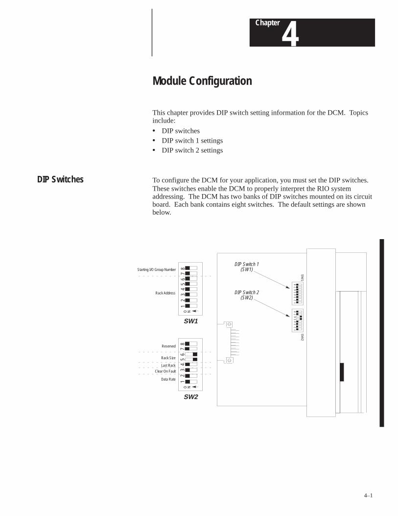
To configure the DCM for your application, you must set the DIP switches.These switches enable the DCM to properly interpret the RIO systemaddressing. The DCM has two banks of DIP switches mounted on its circuitboard. Each bank contains eight switches. The default settings are shownbelow.
SW
1
DIP Switch 1(SW1)
SW
2
DIP Switch 2(SW2)
Reserved
Rack Size
Last Rack
Clear On Fault
8O N
12
34
56
7
SW1
Starting I/O Group Number
Rack Address
O N
SW2
Data Rate
12
34
56
78
81
23
45
67
12
34
56
78
DIP Switches
Chapter 4Module Configuration
4–2
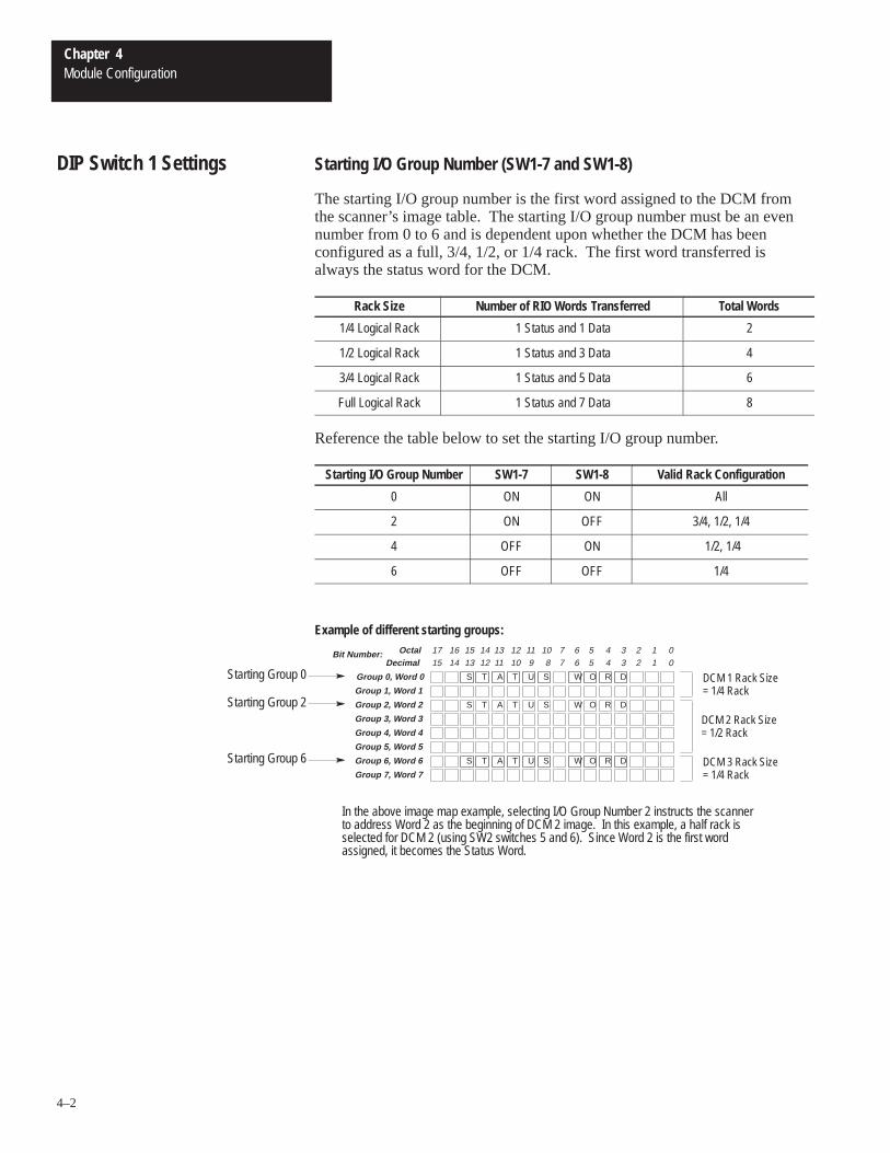
Starting I/O Group Number (SW1-7 and SW1-8)
The starting I/O group number is the first word assigned to the DCM fromthe scanner’s image table. The starting I/O group number must be an evennumber from 0 to 6 and is dependent upon whether the DCM has beenconfigured as a full, 3/4, 1/2, or 1/4 rack. The first word transferred isalways the status word for the DCM.
Rack Size Number of RIO Words Transferred Total Words
1/4 Logical Rack 1 Status and 1 Data 2
1/2 Logical Rack 1 Status and 3 Data 4
3/4 Logical Rack 1 Status and 5 Data 6
Full Logical Rack 1 Status and 7 Data 8
Reference the table below to set the starting I/O group number.
Starting I/O Group Number SW1-7 SW1-8 Valid Rack Configuration
0 ON ON All
2 ON OFF 3/4, 1/2, 1/4
4 OFF ON 1/2, 1/4
6 OFF OFF 1/4
Example of different starting groups:
A SS T T U W O R D
Group 0, Word 0
Group 1, Word 1
Group 2, Word 2
Group 3, Word 3
Group 4, Word 4
Group 5, Word 5
Group 6, Word 6
Group 7, Word 7
DCM 2 Rack Size= 1/2 Rack
R R
In the above image map example, selecting I/O Group Number 2 instructs the scannerto address Word 2 as the beginning of DCM 2 image. In this example, a half rack isselected for DCM 2 (using SW2 switches 5 and 6). Since Word 2 is the first wordassigned, it becomes the Status Word.
DCM 1 Rack Size= 1/4 Rack
DCM 3 Rack Size= 1/4 Rack
Starting Group 2
Starting Group 0
Starting Group 6
A SS T T U W O R D
A SS T T U W O R D
Decimal 15 14 13 12 11 10 9 8 7 6 5 4 3 2 1 0OctalBit Number: 17 16 15 14 13 12 11 10 7 6 5 4 3 2 1 0
DIP Switch 1 Settings
Chapter 4Module Configuration
4–3
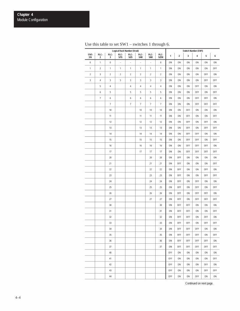
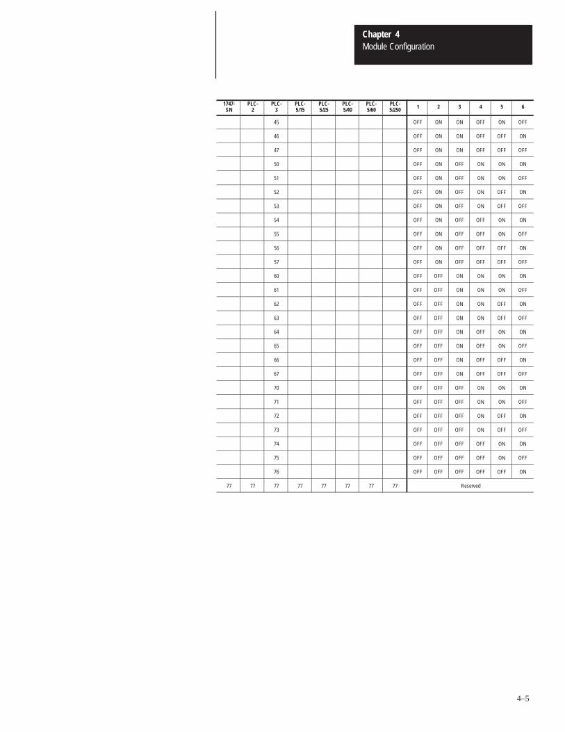
Rack Address (SW1-1 through SW1-6)
The rack address refers to the logical rack number from the scanner imagethat contains a particular DCMs image.
The table on page 4–4 gives the switch settings that define possible rackaddress choices for all scanners. To use this table, first determine which ofthe following categories applies to your scanner:
• PLC-2, mini PLCs, PLC-2/30 with 1772-SD, SD2 remote scanner• PLC-3 and PLC-5/250 processors. (This category includes those with
built-in scanners, as well as the following without built-in scanners:catalog numbers 1775-54A, -54B, -S5, -SR, -SR5 and 5250-RS.)
• PLC-5/11, PLC-5/15, PLC-5/20, PLC-5/25, PLC-5/30, PLC-5/40, orPLC-5/60 and 1771-SN. (This category includes all smaller in-rackprocessors and standalone scanners that have local and remote I/O andbegin rack addressing at rack 1.)
• SLC-5/02 (or above) with 1747-SN scanner
After determining which category applies to your DCM application:
1. Find the column for the scanner used in your application.
2. Go down the column to the rack address that you assigned to the DCM.
3. Use the switch settings in the right-most columns of the table thatcorrespond to your rack address.
Chapter 4Module Configuration
4–4
Use this table to set SW1 – switches 1 through 6.
Logical Rack Number (Octal) Switch Number (SW1)
1747-SN
PLC-2
PLC-3
PLC-5/15
PLC-5/25
PLC-5/40
PLC-5/60
PLC-5/250 1 2 3 4 5 6
0 1 0 – – – – 0 ON ON ON ON ON ON
1 2 1 1 1 1 1 1 ON ON ON ON ON OFF
2 3 2 2 2 2 2 2 ON ON ON ON OFF ON
3 4 3 3 3 3 3 3 ON ON ON ON OFF OFF
5 4 4 4 4 4 ON ON ON OFF ON ON
6 5 5 5 5 5 ON ON ON OFF ON OFF
7 6 6 6 6 6 ON ON ON OFF OFF ON
7 7 7 7 7 ON ON ON OFF OFF OFF
10 10 10 10 ON ON OFF ON ON ON
11 11 11 11 ON ON OFF ON ON OFF
12 12 12 12 ON ON OFF ON OFF ON
13 13 13 13 ON ON OFF ON OFF OFF
14 14 14 14 ON ON OFF OFF ON ON
15 15 15 15 ON ON OFF OFF ON OFF
16 16 16 16 ON ON OFF OFF OFF ON
17 17 17 17 ON ON OFF OFF OFF OFF
20 20 20 ON OFF ON ON ON ON
21 21 21 ON OFF ON ON ON OFF
22 22 22 ON OFF ON ON OFF ON
23 23 23 ON OFF ON ON OFF OFF
24 24 24 ON OFF ON OFF ON ON
25 25 25 ON OFF ON OFF ON OFF
26 26 26 ON OFF ON OFF OFF ON
27 27 27 ON OFF ON OFF OFF OFF
30 30 ON OFF OFF ON ON ON
31 31 ON OFF OFF ON ON OFF
32 32 ON OFF OFF ON OFF ON
33 33 ON OFF OFF ON OFF OFF
34 34 ON OFF OFF OFF ON ON
35 35 ON OFF OFF OFF ON OFF
36 36 ON OFF OFF OFF OFF ON
37 37 ON OFF OFF OFF OFF OFF
40 OFF ON ON ON ON ON
41 OFF ON ON ON ON OFF
42 OFF ON ON ON OFF ON
43 OFF ON ON ON OFF OFF
44 OFF ON ON OFF ON ON
Continued on next page.
Chapter 4Module Configuration
4–5
1747-SN
PLC-2
PLC-3
PLC-5/15
PLC-5/25
PLC-5/40
PLC-5/60
PLC-5/250 1 2 3 4 5 6
45 OFF ON ON OFF ON OFF
46 OFF ON ON OFF OFF ON
47 OFF ON ON OFF OFF OFF
50 OFF ON OFF ON ON ON
51 OFF ON OFF ON ON OFF
52 OFF ON OFF ON OFF ON
53 OFF ON OFF ON OFF OFF
54 OFF ON OFF OFF ON ON
55 OFF ON OFF OFF ON OFF
56 OFF ON OFF OFF OFF ON
57 OFF ON OFF OFF OFF OFF
60 OFF OFF ON ON ON ON
61 OFF OFF ON ON ON OFF
62 OFF OFF ON ON OFF ON
63 OFF OFF ON ON OFF OFF
64 OFF OFF ON OFF ON ON
65 OFF OFF ON OFF ON OFF
66 OFF OFF ON OFF OFF ON
67 OFF OFF ON OFF OFF OFF
70 OFF OFF OFF ON ON ON
71 OFF OFF OFF ON ON OFF
72 OFF OFF OFF ON OFF ON
73 OFF OFF OFF ON OFF OFF
74 OFF OFF OFF OFF ON ON
75 OFF OFF OFF OFF ON OFF
76 OFF OFF OFF OFF OFF ON
77 77 77 77 77 77 77 77 Reserved
Chapter 4Module Configuration
4–6
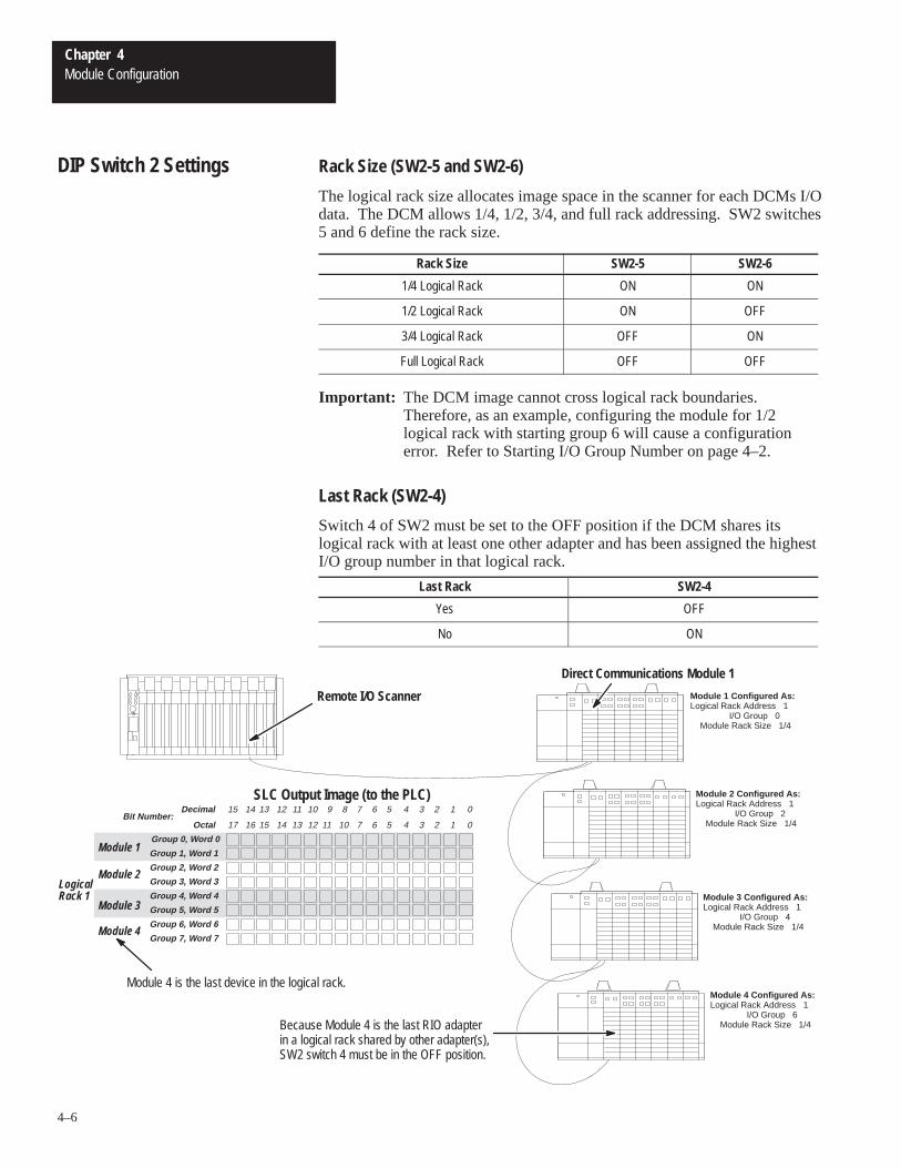
Rack Size (SW2-5 and SW2-6)
The logical rack size allocates image space in the scanner for each DCMs I/Odata. The DCM allows 1/4, 1/2, 3/4, and full rack addressing. SW2 switches5 and 6 define the rack size.
Rack Size SW2-5 SW2-6
1/4 Logical Rack ON ON
1/2 Logical Rack ON OFF
3/4 Logical Rack OFF ON
Full Logical Rack OFF OFF
Important: The DCM image cannot cross logical rack boundaries.Therefore, as an example, configuring the module for 1/2logical rack with starting group 6 will cause a configurationerror. Refer to Starting I/O Group Number on page 4–2.
Last Rack (SW2-4)
Switch 4 of SW2 must be set to the OFF position if the DCM shares itslogical rack with at least one other adapter and has been assigned the highestI/O group number in that logical rack.
Last Rack SW2-4
Yes OFF
No ON
Remote I/O Scanner
SLC Output Image (to the PLC) Module 2 Configured As:Logical Rack Address 1 I/O Group 2 Module Rack Size 1/4
Module 1 Configured As:Logical Rack Address 1 I/O Group 0 Module Rack Size 1/4
Module 3 Configured As:Logical Rack Address 1 I/O Group 4 Module Rack Size 1/4
Module 4 Configured As:Logical Rack Address 1 I/O Group 6 Module Rack Size 1/4
Direct Communications Module 1
Octal 15 14 13 12 11 10 7 6 5 4 3 2 1 0
Group 0, Word 0
Group 1, Word 1
Group 2, Word 2
Group 3, Word 3
Group 4, Word 4
Group 5, Word 5
Group 6, Word 6
Group 7, Word 7
17 16
Module 1
Module 2
Module 3
Module 4
Module 4 is the last device in the logical rack.
Because Module 4 is the last RIO adapterin a logical rack shared by other adapter(s),SW2 switch 4 must be in the OFF position.
LogicalRack 1
13 12 11 10 9 8 7 6 5 4 3 2 1 015 14DecimalBit Number:
DIP Switch 2 Settings
Chapter 4Module Configuration
4–7
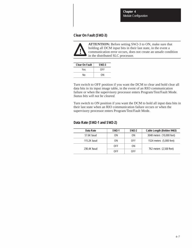
Clear On Fault (SW2-3)
!ATTENTION: Before setting SW2-3 to ON, make sure thatholding all DCM input bits in their last state, in the event acommunication error occurs, does not create an unsafe conditionin the distributed SLC processor.
Clear On Fault SW2-3
Yes OFF
No ON
Turn switch to OFF position if you want the DCM to clear and hold clear alldata bits in its input image table, in the event of an RIO communicationfailure or when the supervisory processor enters Program/Test/Fault Mode. Status bits will not be cleared.
Turn switch to ON position if you want the DCM to hold all input data bits intheir last state when an RIO communication failure occurs or when thesupervisory processor enters Program/Test/Fault Mode.
Data Rate (SW2-1 and SW2-2)
Data Rate SW2-1 SW2-2 Cable Length (Belden 9463)
57.6K baud ON ON 3048 meters (10,000 feet)
115.2K baud ON OFF 1524 meters (5,000 feet)
3 bOFF ON
7 r f230.4K baudOFF OFF
762 meters (2,500 feet)

5Chapter
5–1
Installation and Wiring
This chapter explains how to install the DCM into the SLC chassis andprovides information about terminal wiring. Topics include:
• DCM installation• network wiring
If this product has the CE mark it is approved for installation within theEuropean Union and EEA regions. It has been designed and tested to meetthe following directives.
EMC Directive
This product is tested to meet Council Directive 89/336/EECElectromagnetic Compatibility (EMC) and the following standards, in wholeor in part, documented in a technical construction file:
• EN 50081-2EMC – Generic Emission Standard, Part 2 – Industrial Environment
• EN 50082-2EMC – Generic Immunity Standard, Part 2 – Industrial Environment
This product is intended for use in an industrial environment.
Installation procedures for this module are the same as for any other discreteI/O or specialty module. Refer to the illustration on page 5–2 to identifychassis and module components listed in the procedures below.
!ATTENTION: Disconnect power before attempting to install,remove, or wire the DCM.
Important: Make sure you have set the DIP switches properly beforeinstalling the DCM.
Before installation make sure your modular SLC power supplyhas adequate reserve current capacity. The DCM requires360mA @ 5 volts. Each Fixed SLC 500 controller can supportup to one DCM in a 2-slot expansion chassis, depending onwhich I/O module is in the second slot. Refer to the DiscreteI/O Modules Product Data, Publication Number 1746-2.35.
Compliance to EuropeanUnion Directives
DCM Installation
Chapter 5Installation and Wiring
5–2
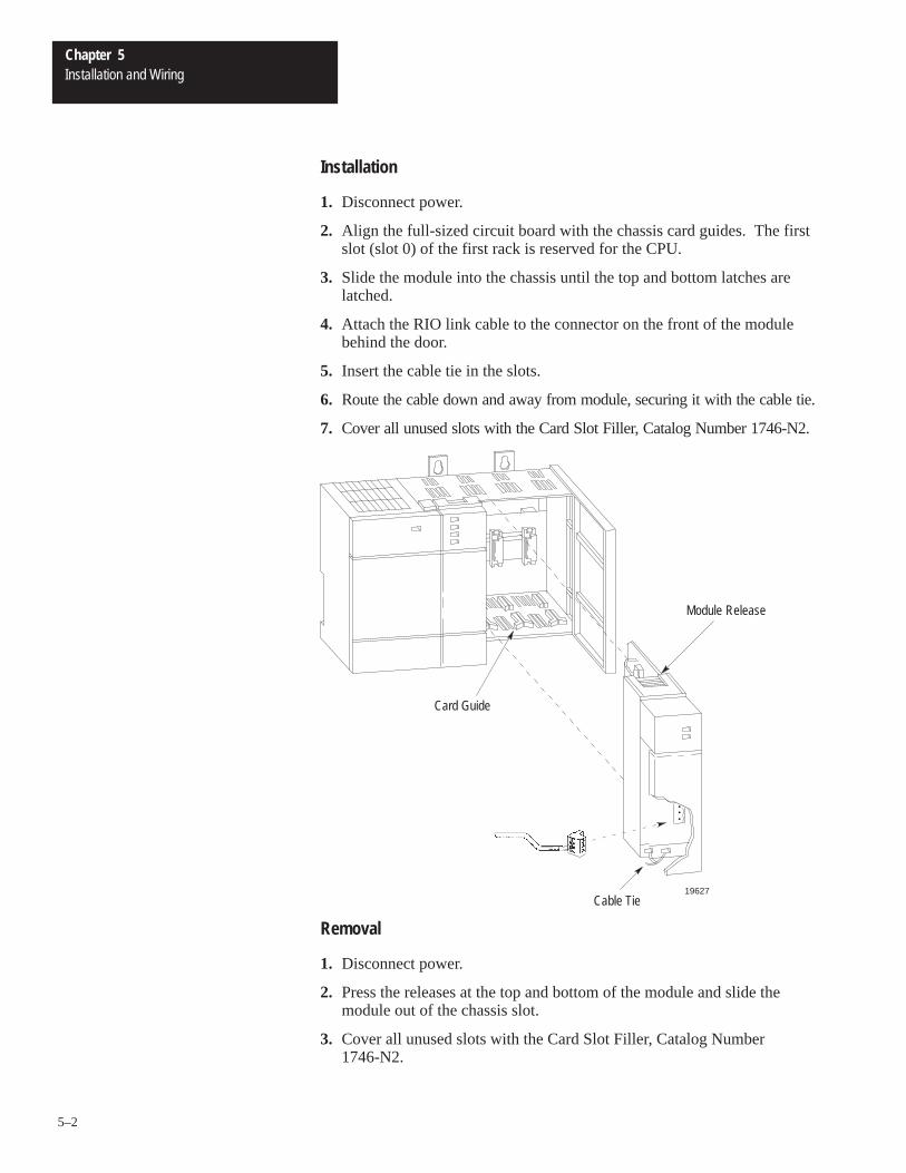
Installation
1. Disconnect power.
2. Align the full-sized circuit board with the chassis card guides. The firstslot (slot 0) of the first rack is reserved for the CPU.
3. Slide the module into the chassis until the top and bottom latches arelatched.
4. Attach the RIO link cable to the connector on the front of the modulebehind the door.
5. Insert the cable tie in the slots.
6. Route the cable down and away from module, securing it with the cable tie.
7. Cover all unused slots with the Card Slot Filler, Catalog Number 1746-N2.
.
.
.
Card Guide
Cable Tie
Module Release
19627
Removal
1. Disconnect power.
2. Press the releases at the top and bottom of the module and slide themodule out of the chassis slot.
3. Cover all unused slots with the Card Slot Filler, Catalog Number1746-N2.
Chapter 5Installation and Wiring
5–3
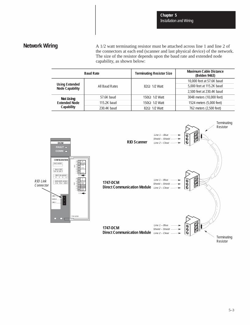
A 1/2 watt terminating resistor must be attached across line 1 and line 2 ofthe connectors at each end (scanner and last physical device) of the network.The size of the resistor depends upon the baud rate and extended nodecapability, as shown below:
Baud Rate Terminating Resistor Size Maximum Cable Distance(Belden 9463)
Using ExtendedNode Capability All Baud Rates 82� 1/2 Watt
10,000 feet at 57.6K baud5,000 feet at 115.2K baud
2,500 feet at 230.4K baud
Not Using 57.6K baud 150� 1/2 Watt 3048 meters (10,000 feet)Not UsingExtended Node
apab l t115.2K baud 150� 1/2 Watt 1524 meters (5,000 feet)xten e o e
Capability 230.4K baud 82� 1/2 Watt 762 meters (2,500 feet)
TerminatingResistor
TerminatingResistor
RIO Scanner
1747-DCMDirect Communication Module
1747-DCMDirect Communication Module
Line 1 – Blue
Shield – Shield
Line 2 – Clear
Line 1 – Blue
Shield – Shield
Line 2 – Clear
Line 1 – Blue
Shield – Shield
Line 2 – Clear
DCM
RIO LinkConnector
COMM
FAULT
CONFIGURATION
RACK SIZE1/4 1/2 3/4 1
RACK ADDR
FIRST I/O GROUP0 2 4 6
DATA RATE (K B/S)57.6 115.2 230.4
LINE 1 _______
SHIELD ______
LINE 2 _______
1747–DCM
SW
2S
W1
O N
12
34
56
78
O N
12
34
56
78
I/OGROUP
(LSB)
RACKADDRESS
(MSB)
RACKSIZE
DATARATE
XX
LAST RACK
CLR ON FLT
Network Wiring

6Chapter
6–1
Programming
This chapter shows you how to program ladder logic in the supervisoryprocessor/scanner and the distributed SLC to transfer data via the DCM.Topics include:
• overview• programming examples• status words• applications using status word bits
Both the supervisory processor/scanner and the distributed SLC transfer datato and from the DCM automatically via their I/O and the RIO scan. TheDCM, as a common memory site for both supervisory and distributedprocessors, has two addresses; one for the supervisory processor/scanner and one for the SLC. The supervisory processor/scanner address isthe DCM logical rack address as set by DCM SW-1 switches 1 through 6.The distributed SLC address is determined by the slot where the DCM isphysically installed.
The supervisory processor/scanner and distributed SLC addresses can bedifferent; however, the bit position part in each word must be the same.
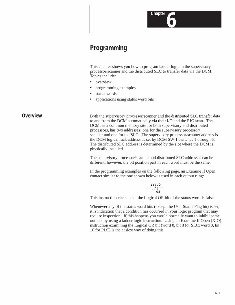
In the programming examples on the following page, an Examine If Opencontact similar to the one shown below is used in each output rung:
]/[I:4.0
08
This instruction checks that the Logical OR bit of the status word is false.
Whenever any of the status word bits (except the User Status Flag bit) is set,it is indication that a condition has occurred in your logic program that mayrequire inspection. If this happens you would normally want to inhibit someoutputs by using a ladder logic instruction. Using an Examine If Open (XIO)instruction examining the Logical OR bit (word 0, bit 8 for SLC; word 0, bit10 for PLC) is the easiest way of doing this.
Overview
Chapter 6Programming
6–2
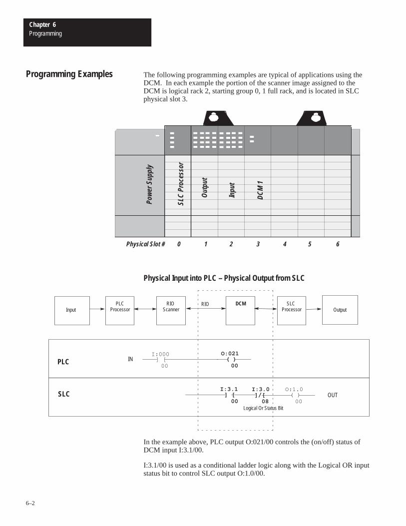
The following programming examples are typical of applications using theDCM. In each example the portion of the scanner image assigned to theDCM is logical rack 2, starting group 0, 1 full rack, and is located in SLCphysical slot 3.
DCM
1
Inpu
t
Out
put
SLC
Proc
esso
r
Pow
er S
uppl
y
Physical Slot # 0 1 2 3 4 5 6
Physical Input into PLC – Physical Output from SLC
] [I:000
00( )
O:021
00
] [I:3.1
00]/[
I:3.0
08( )
O:1.0
00
PLC
SLC
PLCProcessor
RIO Scanner
DCM SLC Processor
RIOInput Output
IN
OUT
Logical Or Status Bit
In the example above, PLC output O:021/00 controls the (on/off) status ofDCM input I:3.1/00.
I:3.1/00 is used as a conditional ladder logic along with the Logical OR inputstatus bit to control SLC output O:1.0/00.
Programming Examples
Chapter 6Programming
6–3
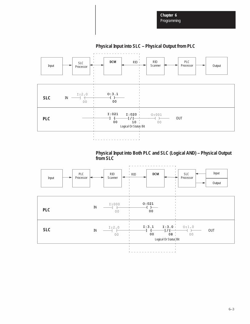
Physical Input into SLC – Physical Output from PLC
ÇÇÇÇÇÇÇÇÇÇÇÇÇÇÇÇÇÇÇÇÇÇÇÇÇÇÇÇÇÇÇÇÇÇÇÇÇÇÇÇÇÇÇÇÇÇÇÇÇÇÇÇÇÇÇÇÇÇÇÇÇÇÇÇÇÇÇÇÇÇÇÇÇÇÇÇÇÇÇÇÇÇÇÇÇÇÇÇÇÇÇÇÇÇÇÇÇÇÇÇÇÇÇÇÇÇÇÇÇÇÇÇÇÇÇÇÇÇÇÇÇÇÇÇÇÇÇÇÇÇÇÇÇÇÇÇÇÇÇÇÇÇÇÇÇÇÇÇÇÇÇÇÇÇÇÇÇÇÇÇÇÇÇÇÇ
] [ 00
( ) 00
] [ 00
]/[ 10
( )O:001
00PLC
SLC
PLCProcessor
RIO Scanner
DCMSLC Processor
RIOInput Output
IN
OUTI:021 I:020
I:2.0 O:3.1
Logical Or Status Bit
Physical Input into Both PLC and SLC (Logical AND) – Physical Outputfrom SLC
] [I:000
00( )
O:021
00
] [I:3.1
00]/[
I:3.0
08( )
O:1.0
00
PLC
SLC
PLCProcessor
RIO Scanner
DCM SLC Processor
RIOInput
Output
Input
] [ 00
IN
OUTINI:2.0
Logical Or Status Bit
Chapter 6Programming
6–4
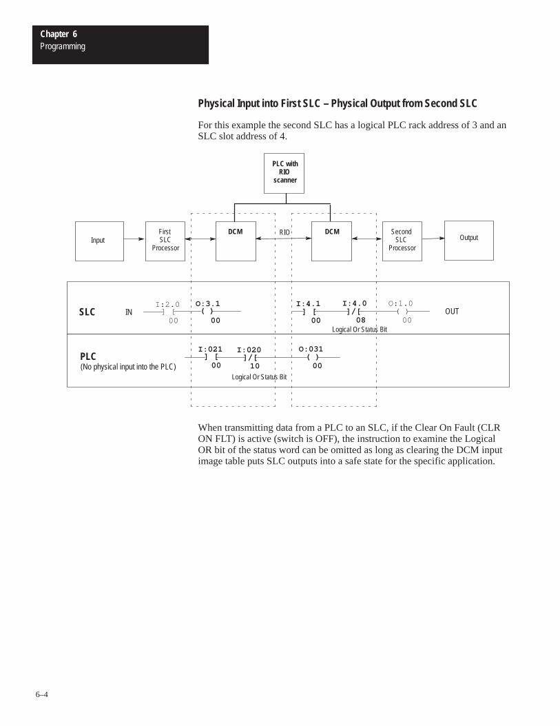
Physical Input into First SLC – Physical Output from Second SLC
For this example the second SLC has a logical PLC rack address of 3 and anSLC slot address of 4.
I:020
10( )
O:031
00
O:3.1
00]/[
I:4.0
08( )
O:1.0
00SLC
PLC
First SLC
Processor
DCM Second SLC
Processor
RIOInput Output
] [I:021
00
OUT
DCM
] [ 00
IN ] [I:4.1
00
(No physical input into the PLC)]/[
I:2.0
PLC withRIO
scanner
Logical Or Status Bit
Logical Or Status Bit
( )
When transmitting data from a PLC to an SLC, if the Clear On Fault (CLRON FLT) is active (switch is OFF), the instruction to examine the LogicalOR bit of the status word can be omitted as long as clearing the DCM inputimage table puts SLC outputs into a safe state for the specific application.
Chapter 6Programming
6–5
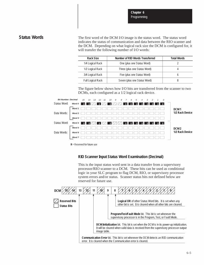
The first word of the DCM I/O image is the status word. The status wordindicates the status of communication and data between the RIO scanner andthe DCM. Depending on what logical rack size the DCM is configured for, itwill transfer the following number of I/O words:
Rack Size Number of RIO Words Transferred Total Words
1/4 Logical Rack One (plus one Status Word) 2
1/2 Logical Rack Three (plus one Status Word) 4
3/4 Logical Rack Five (plus one Status Word) 6
Full Logical Rack Seven (plus one Status Word) 8
The figure below shows how I/O bits are transferred from the scanner to twoDCMs, each configured as a 1/2 logical rack device.
RÍÍÍÍ
ÍÍÍÍ
ÍÍÍÍR
ÍÍ
15 14 13 12 11 10 9 8 7 6 5 4 3 2 1 0
R R R RR RR RWord 0
Word 1
Word 2
Word 3
Word 4
Word 5
Word 6
Word 7
DCM 11/2 Rack Device
ÍÍÍÍ
ÍÍÍÍ
R RÍÍ
R R R RR RR RÍÍÍÍ DCM 2
1/2 Rack Device
Status Word:
Status Word:
R R
R R
RR
RR
Data Words:
Data Words:
R = Reserved for future use
Bit Number: Decimal
RIO Scanner Input Status Word Examination (Decimal)
This is the input status word sent in a data transfer from a supervisoryprocessor/RIO scanner to a DCM. These bits can be used as conditionallogic in your SLC program to flag DCM, RIO, or supervisory processorsystem errors and/or status. Scanner status bits not defined below arereserved for future use.
DCM Initialization bit. This bit is set when the DCM is in its power-up initialization.It will be cleared when valid data is received from the supervisory processor outputimage table.
ÉÉÉÉÉÉÉÉ
ÉÉÉÉÉÉÉÉÉÉÉÉÉÉÉÉÉÉÉÉÉÉÉÉÉÉÉÉÉÉÉÉÉÉÉÉÉÉÉÉÉÉÉÉÉÉÉÉÉÉÉÉÉÉÉÉÉÉÉÉÉÉ
Program/Test/Fault Mode bit. This bit is set whenever thesupervisory processor is in the Program, Test, or Fault Mode.
ÉÉÉÉ
0ÉÉÉÉ
1ÉÉÉÉ
3ÉÉÉÉ
4 ÉÉ
2ÉÉ
5ÉÉÉÉ
6ÉÉ
8ÉÉÉÉ
9 ÉÉÉÉ
7ÉÉÉÉ
10ÉÉÉÉ
11ÉÉÉÉ
14 ÉÉÉÉ
12ÉÉÉÉ
15
Logical OR of other Status Word bits. It is set when anyother bit is set. It is cleared when all other bits are cleared.
Communication Error bit. This bit is set whenever the DCM detects an RIO communicationerror. It is cleared when the Communication error is cleared.
Reserved Bits
ÍÍÍÍ
13DCM
ÉÉÉÉStatus Bits
Status Words
Chapter 6Programming
6–6
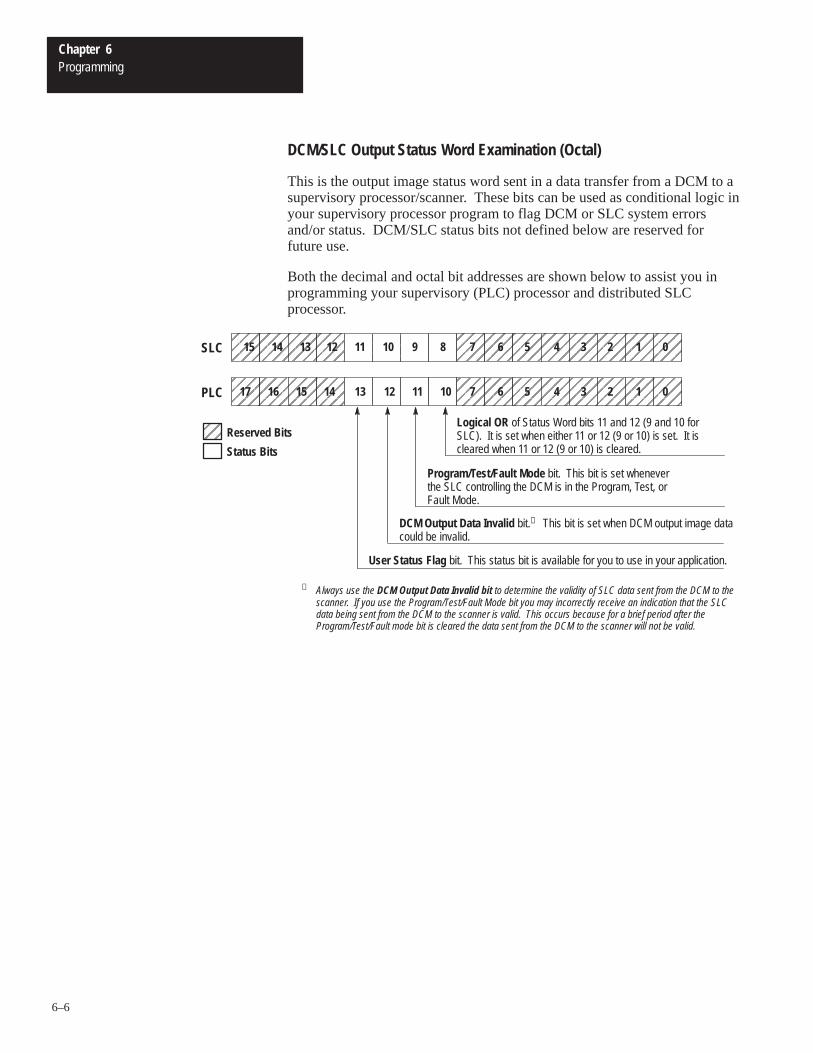
DCM/SLC Output Status Word Examination (Octal)
This is the output image status word sent in a data transfer from a DCM to asupervisory processor/scanner. These bits can be used as conditional logic inyour supervisory processor program to flag DCM or SLC system errorsand/or status. DCM/SLC status bits not defined below are reserved forfuture use.
Both the decimal and octal bit addresses are shown below to assist you inprogramming your supervisory (PLC) processor and distributed SLCprocessor.
Logical OR of Status Word bits 11 and 12 (9 and 10 forSLC). It is set when either 11 or 12 (9 or 10) is set. It iscleared when 11 or 12 (9 or 10) is cleared.
Program/Test/Fault Mode bit. This bit is set wheneverthe SLC controlling the DCM is in the Program, Test, orFault Mode.
DCM Output Data Invalid bit.➀ This bit is set when DCM output image datacould be invalid.
User Status Flag bit. This status bit is available for you to use in your application.
ÉÉÉÉÉÉÉÉÉÉ
ÉÉÉÉ
ÉÉÉÉÉÉÉÉÉÉÉÉÉÉÉÉÉÉÉÉÉÉÉÉÉÉÉÉÉÉÉÉÉÉÉÉÉÉ
ÉÉÉÉ
ÉÉ
0ÉÉÉÉ
1ÉÉ
3ÉÉÉÉ
4ÉÉÉÉ
2ÉÉÉÉ
5ÉÉ
6ÍÍÍÍ
10ÍÍÍÍ
11ÉÉÉÉ
7ÍÍÍÍ
12ÍÍÍÍ
13ÉÉÉÉ
16ÉÉÉÉ
14ÉÉÉÉ
17ÉÉÉÉ
15PLC
Reserved BitsÉÉÉÉStatus Bits
ÉÉÉÉÉÉÉÉÉÉ
ÉÉÉÉÉÉÉÉÉÉÉÉÉÉÉÉÉÉÉÉÉÉÉÉÉÉÉÉÉÉÉÉÉÉÉÉÉÉÉÉÉÉÉÉÉÉÉÉÉÉÉÉÉÉÉÉÉÉÉÉÉÉ
ÉÉÉÉ
ÉÉ
0ÉÉÉÉ
1ÉÉ
3ÉÉÉÉ
4 ÉÉÉÉ
2ÉÉÉÉ
5ÉÉ
6ÉÉ
8ÉÉÉÉ
9 ÉÉÉÉ
7ÉÉÉÉ
10ÉÉÉÉ
11ÉÉÉÉ
14 ÉÉÉÉ
12ÉÉÉÉ
15 ÉÉÉÉ
13SLC
➀ Always use the DCM Output Data Invalid bit to determine the validity of SLC data sent from the DCM to thescanner. If you use the Program/Test/Fault Mode bit you may incorrectly receive an indication that the SLCdata being sent from the DCM to the scanner is valid. This occurs because for a brief period after theProgram/Test/Fault mode bit is cleared the data sent from the DCM to the scanner will not be valid.
Chapter 6Programming
6–7
You can use the status bits in your ladder logic to monitor various conditionsof the remote processor and the RIO network. Some examples for using thestatus word bits are given here. Each of the examples shows how ladderlogic rungs could be programmed in the SLC processor to respond to thecondition of a status bit from the RIO scanner.
Important: The application examples assume the portion of the scannerimage assigned to the DCM is logical rack 2, starting group 0, 1full rack, and is located in SLC physical slot 3.
RIO Scanner Status Word
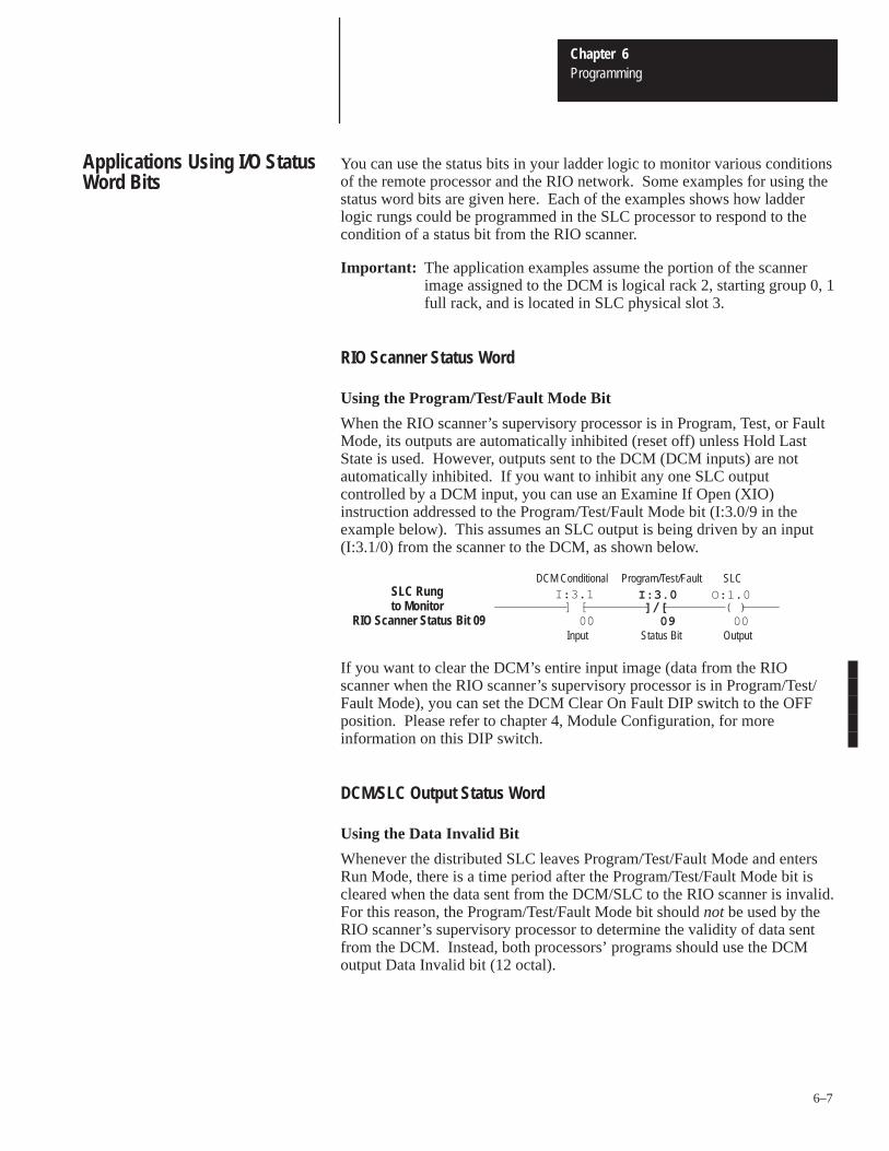
Using the Program/Test/Fault Mode Bit
When the RIO scanner’s supervisory processor is in Program, Test, or FaultMode, its outputs are automatically inhibited (reset off) unless Hold LastState is used. However, outputs sent to the DCM (DCM inputs) are notautomatically inhibited. If you want to inhibit any one SLC outputcontrolled by a DCM input, you can use an Examine If Open (XIO)instruction addressed to the Program/Test/Fault Mode bit (I:3.0/9 in theexample below). This assumes an SLC output is being driven by an input(I:3.1/0) from the scanner to the DCM, as shown below.
] [I:3.1
00]/[
I:3.0
09( )
O:1.0
00
SLC Rung to Monitor
RIO Scanner Status Bit 09
DCM Conditional Program/Test/Fault SLC
OutputStatus BitInput
If you want to clear the DCM’s entire input image (data from the RIOscanner when the RIO scanner’s supervisory processor is in Program/Test/Fault Mode), you can set the DCM Clear On Fault DIP switch to the OFFposition. Please refer to chapter 4, Module Configuration, for moreinformation on this DIP switch.
DCM/SLC Output Status Word
Using the Data Invalid Bit
Whenever the distributed SLC leaves Program/Test/Fault Mode and entersRun Mode, there is a time period after the Program/Test/Fault Mode bit iscleared when the data sent from the DCM/SLC to the RIO scanner is invalid.For this reason, the Program/Test/Fault Mode bit should not be used by theRIO scanner’s supervisory processor to determine the validity of data sentfrom the DCM. Instead, both processors’ programs should use the DCMoutput Data Invalid bit (12 octal).
Applications Using I/O StatusWord Bits
Chapter 6Programming
6–8
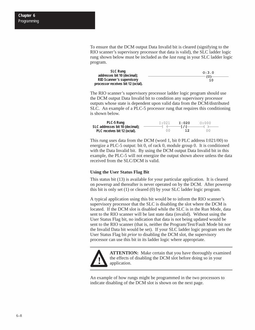
To ensure that the DCM output Data Invalid bit is cleared (signifying to theRIO scanner’s supervisory processor that data is valid), the SLC ladder logicrung shown below must be included as the last rung in your SLC ladder logicprogram.
O:3.0
10
SLC Rung addresses bit 10 (decimal); RIO Scanner ’s supervisory
processor receives bit 12 (octal).
(U)
The RIO scanner’s supervisory processor ladder logic program should usethe DCM output Data Invalid bit to condition any supervisory processoroutputs whose state is dependent upon valid data from the DCM/distributedSLC. An example of a PLC-5 processor rung that requires this conditioningis shown below.
] [I:021
00]/[
I:020
12( )
O:000
00
PLC-5 Rung SLC addresses bit 10 (decimal);
PLC receives bit 12 (octal).
This rung uses data from the DCM (word 1, bit 0 PLC address I:021/00) toenergize a PLC-5 output: bit 0, of rack 0, module group 0. It is conditionedwith the Data Invalid bit. By using the DCM output Data Invalid bit in thisexample, the PLC-5 will not energize the output shown above unless the datareceived from the SLC/DCM is valid.
Using the User Status Flag Bit
This status bit (13) is available for your particular application. It is clearedon powerup and thereafter is never operated on by the DCM. After powerupthis bit is only set (1) or cleared (0) by your SLC ladder logic program.
A typical application using this bit would be to inform the RIO scanner’ssupervisory processor that the SLC is disabling the slot where the DCM islocated. If the DCM slot is disabled while the SLC is in the Run Mode, datasent to the RIO scanner will be last state data (invalid). Without using theUser Status Flag bit, no indication that data is not being updated would besent to the RIO scanner (that is, neither the Program/Test/Fault Mode bit northe Invalid Data bit would be set). If your SLC ladder logic program sets theUser Status Flag bit prior to disabling the DCM slot, the supervisoryprocessor can use this bit in its ladder logic where appropriate.
!ATTENTION: Make certain that you have thoroughly examinedthe effects of disabling the DCM slot before doing so in yourapplication.
An example of how rungs might be programmed in the two processors toindicate disabling of the DCM slot is shown on the next page.
Chapter 6Programming
6–9
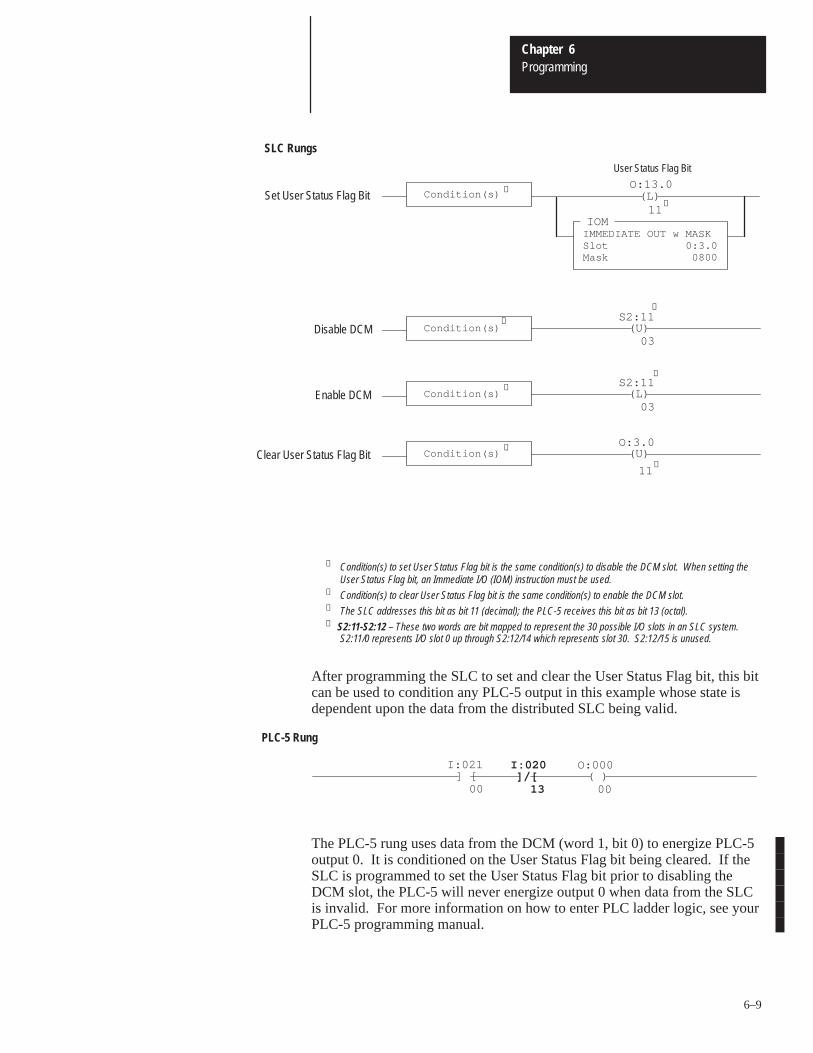
SLC Rungs
IOMIMMEDIATE OUT w MASKSlot 0:3.0Mask 0800
Condition(s) (L)O:13.0
11Set User Status Flag Bit
Condition(s) Disable DCM (U)S2:11
03
➃
Condition(s) Enable DCM (L)S2:11
03
Condition(s) Clear User Status Flag Bit (U)O:3.0
➁
➁
➀
➀
➂
➃
11➂
User Status Flag Bit
➀ Condition(s) to set User Status Flag bit is the same condition(s) to disable the DCM slot. When setting theUser Status Flag bit, an Immediate I/O (IOM) instruction must be used.
➁ Condition(s) to clear User Status Flag bit is the same condition(s) to enable the DCM slot.➂ The SLC addresses this bit as bit 11 (decimal); the PLC-5 receives this bit as bit 13 (octal).➃ S2:11-S2:12 – These two words are bit mapped to represent the 30 possible I/O slots in an SLC system.
S2:11/0 represents I/O slot 0 up through S2:12/14 which represents slot 30. S2:12/15 is unused.
After programming the SLC to set and clear the User Status Flag bit, this bitcan be used to condition any PLC-5 output in this example whose state isdependent upon the data from the distributed SLC being valid.
PLC-5 Rung
] [I:021
00]/[
I:020
13( )
O:000
00
The PLC-5 rung uses data from the DCM (word 1, bit 0) to energize PLC-5output 0. It is conditioned on the User Status Flag bit being cleared. If theSLC is programmed to set the User Status Flag bit prior to disabling theDCM slot, the PLC-5 will never energize output 0 when data from the SLCis invalid. For more information on how to enter PLC ladder logic, see yourPLC-5 programming manual.
Chapter 6Programming
6–10
RIO Scanner Input Status and DCM/SLC Output Status
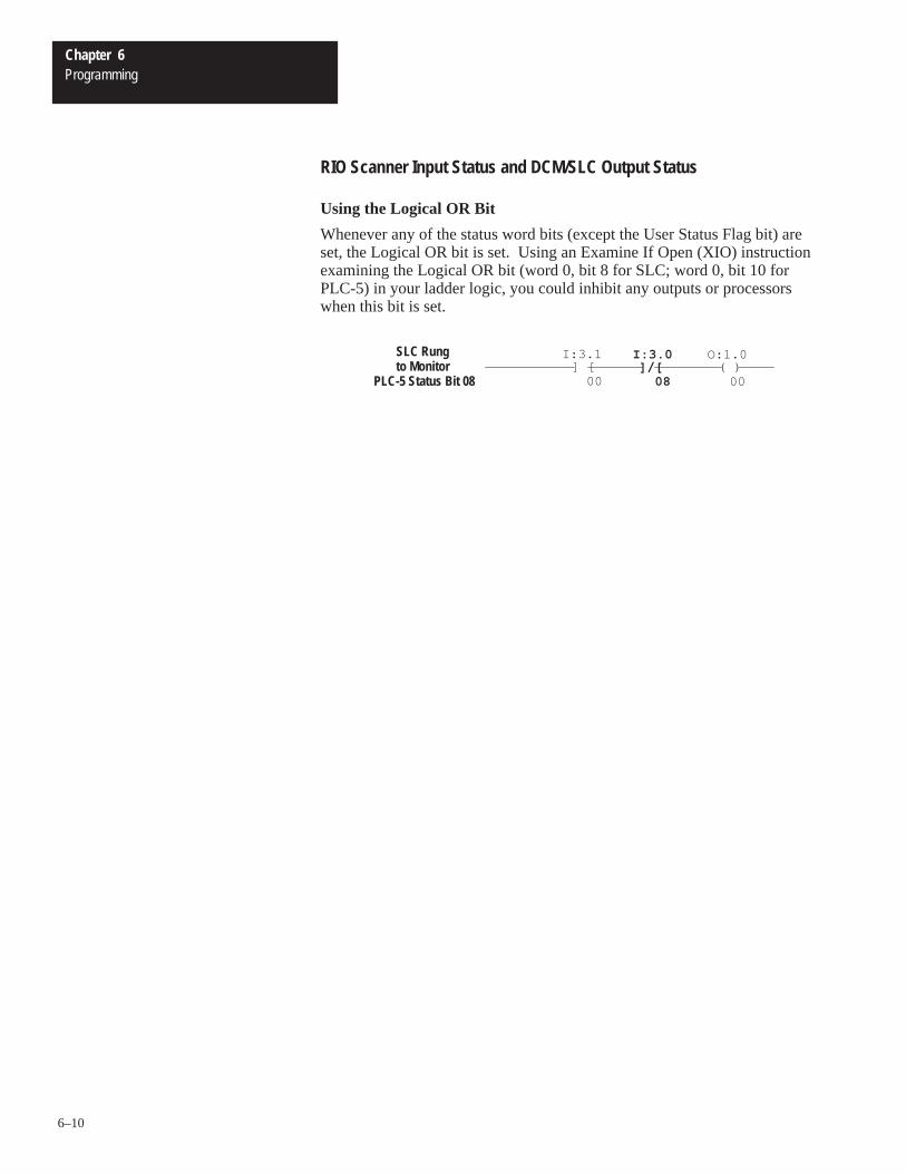
Using the Logical OR Bit
Whenever any of the status word bits (except the User Status Flag bit) areset, the Logical OR bit is set. Using an Examine If Open (XIO) instructionexamining the Logical OR bit (word 0, bit 8 for SLC; word 0, bit 10 forPLC-5) in your ladder logic, you could inhibit any outputs or processorswhen this bit is set.
] [I:3.1
00]/[
I:3.0
08( )
O:1.0
00
SLC Rung to Monitor
PLC-5 Status Bit 08
7Chapter
7–1
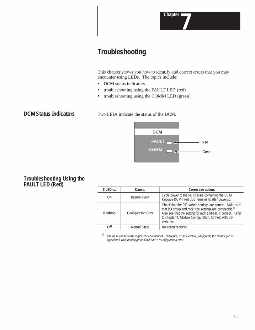
Troubleshooting
This chapter shows you how to identify and correct errors that you mayencounter using LEDs. The topics include:
• DCM status indicators• troubleshooting using the FAULT LED (red)• troubleshooting using the COMM LED (green)
Two LEDs indicate the status of the DCM.
Red
Green
DCM
COMM
FAULT
If LED is: Cause: Corrective action:
On Internal Fault Cycle power to the I/O chassis containing the DCM.Replace DCM if red LED remains lit after powerup.
Blinking Configuration Error
Check that the DIP switch settings are correct. Make surethat I/O group and rack size settings are compatible.➀
Also see that the setting for rack address is correct. Referto chapter 4, Module Configuration, for help with DIPswitches.
Off Normal State No action required.
➀ The DCM cannot cross logical rack boundaries. Therefore, as an example, configuring the module for 1/2logical rack with starting group 6 will cause a configuration error.
DCM Status Indicators
Troubleshooting Using theFAULT LED (Red)
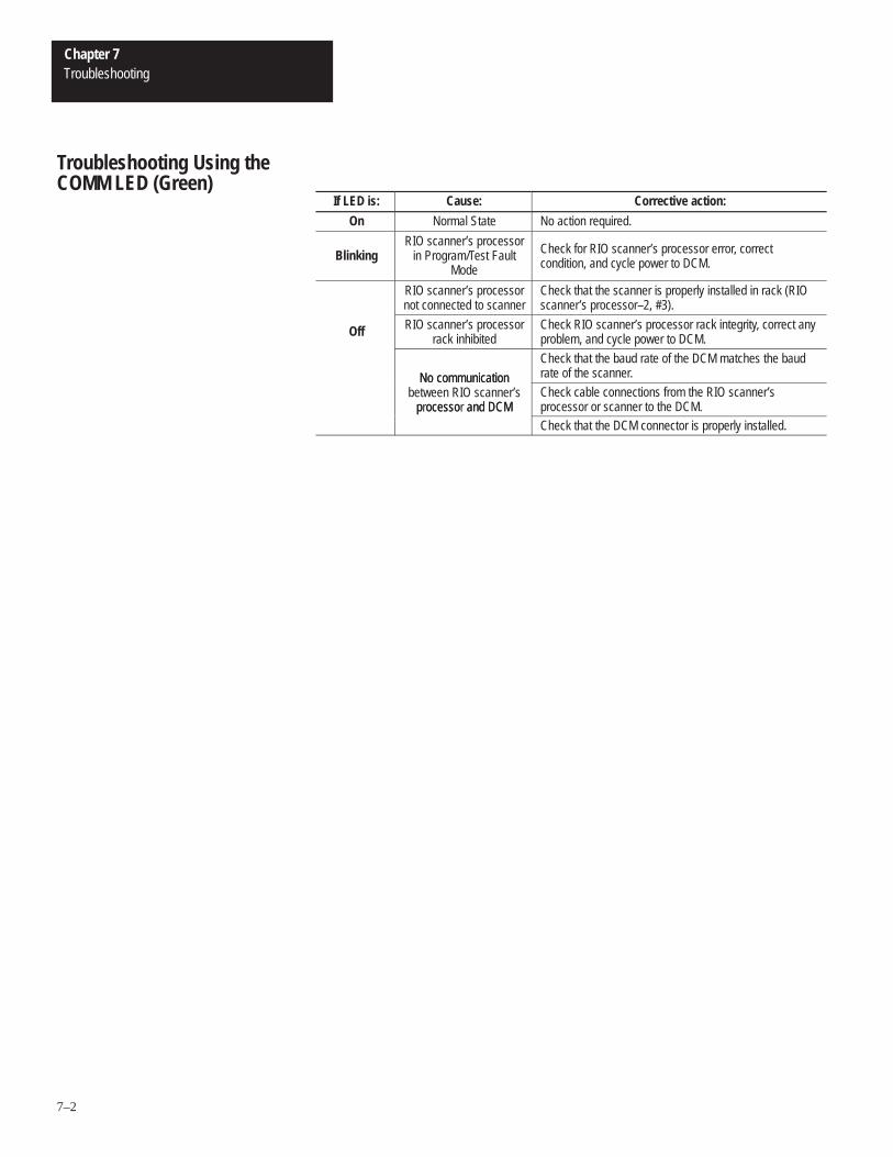
Chapter 7Troubleshooting
7–2
If LED is: Cause: Corrective action:
On Normal State No action required.
BlinkingRIO scanner’s processor
in Program/Test FaultMode
Check for RIO scanner’s processor error, correctcondition, and cycle power to DCM.
RIO scanner’s processornot connected to scanner
Check that the scanner is properly installed in rack (RIOscanner’s processor–2, #3).
Off RIO scanner’s processorrack inhibited
Check RIO scanner’s processor rack integrity, correct anyproblem, and cycle power to DCM.
No communication
Check that the baud rate of the DCM matches the baudrate of the scanner.No communication
between RIO scanner’sprocessor and DCM
Check cable connections from the RIO scanner’sprocessor or scanner to the DCM.processor and DCMCheck that the DCM connector is properly installed.
Troubleshooting Using theCOMM LED (Green)
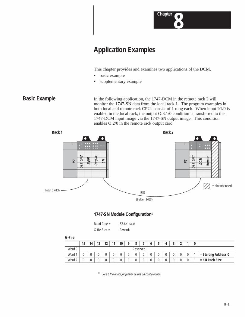
8Chapter
8–1
Application Examples
This chapter provides and examines two applications of the DCM.
• basic example• supplementary example
In the following application, the 1747-DCM in the remote rack 2 willmonitor the 1747-SN data from the local rack 1. The program examples inboth local and remote rack CPUs consist of 1 rung each. When input I:1/0 isenabled in the local rack, the output O:3.1/0 condition is transferred to the1747-DCM input image via the 1747-SN output image. This conditionenables O:2/0 in the remote rack output card.
RIO
(Belden 9463)
ÉÉÉÉÉÉ
ÉÉÉÉÉÉ
Rack 1 Rack 2
ÉÉÉÉÉÉÉÉÉÉÉÉÉÉÉÉÉÉ
= slot not used
SLC
5/02
Inpu
t
Out
put
SNP2
Out
put
DCM
SLC
5/01
P2Input Switch
1747-SN Module Configuration➀
Baud Rate = 57.6K baud
G-file Size = 3 words
G-File15 14 13 12 11 10 9 8 7 6 5 4 3 2 1 0
Word 0 Reserved
Word 1 0 0 0 0 0 0 0 0 0 0 0 0 0 0 0 1 = Starting Address 0
Word 2 0 0 0 0 0 0 0 0 0 0 0 0 0 0 0 1 = 1/4 Rack Size
➀ See SN manual for further details on configuration.
Basic Example
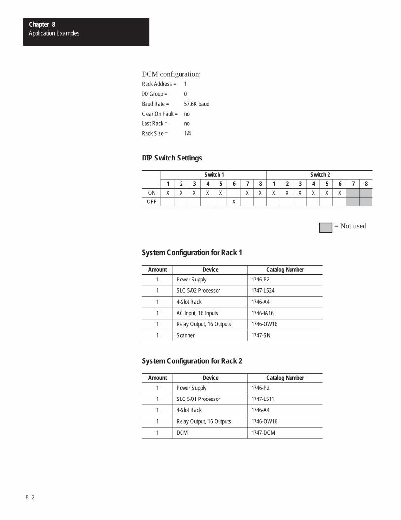
Chapter 8Application Examples
8–2
DCM configuration:Rack Address = 1
I/O Group = 0
Baud Rate = 57.6K baud
Clear On Fault = no
Last Rack = no
Rack Size = 1/4
DIP Switch Settings
Switch 1 Switch 2
1 2 3 4 5 6 7 8 1 2 3 4 5 6 7 8
ON X X X X X X X X X X X X X
OFF X
= Not used
System Configuration for Rack 1
Amount Device Catalog Number
1 Power Supply 1746-P2
1 SLC 5/02 Processor 1747-L524
1 4-Slot Rack 1746-A4
1 AC Input, 16 Inputs 1746-IA16
1 Relay Output, 16 Outputs 1746-OW16
1 Scanner 1747-SN
System Configuration for Rack 2
Amount Device Catalog Number
1 Power Supply 1746-P2
1 SLC 5/01 Processor 1747-L511
1 4-Slot Rack 1746-A4
1 Relay Output, 16 Outputs 1746-OW16
1 DCM 1747-DCM
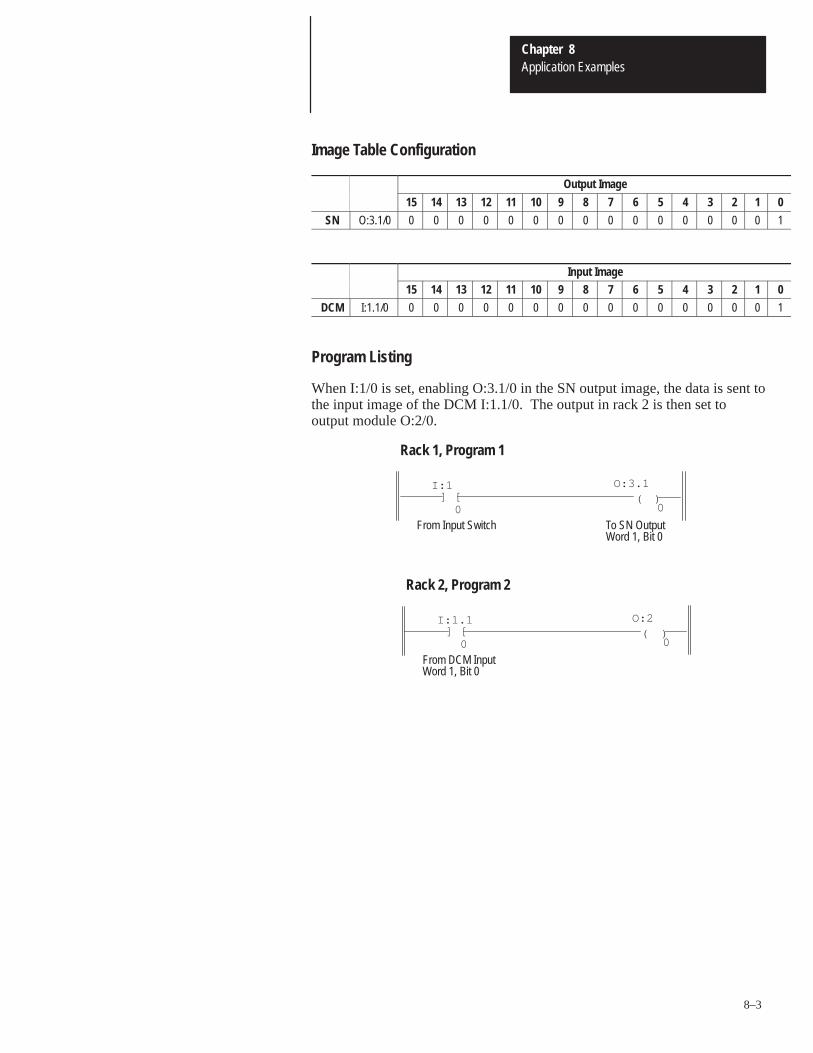
Chapter 8Application Examples
8–3
Image Table Configuration
Output Image
15 14 13 12 11 10 9 8 7 6 5 4 3 2 1 0
SN O:3.1/0 0 0 0 0 0 0 0 0 0 0 0 0 0 0 0 1
Input Image15 14 13 12 11 10 9 8 7 6 5 4 3 2 1 0
DCM I:1.1/0 0 0 0 0 0 0 0 0 0 0 0 0 0 0 0 1
Program Listing
When I:1/0 is set, enabling O:3.1/0 in the SN output image, the data is sent tothe input image of the DCM I:1.1/0. The output in rack 2 is then set tooutput module O:2/0.
] [I:1
0
O:3.1
0( )
From Input Switch To SN OutputWord 1, Bit 0
Rack 1, Program 1
] [I:1.1
0
O:2
0( )
From DCM Input
Rack 2, Program 2
Word 1, Bit 0
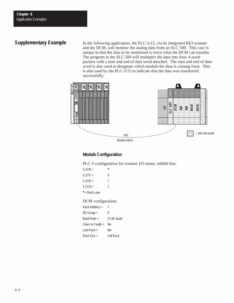
Chapter 8Application Examples
8–4
In the following application, the PLC-5/15, via its integrated RIO scannerand the DCM, will monitor the analog data from an SLC 500. This case isunique in that the data to be monitored is twice what the DCM can transfer.The program in the SLC 500 will multiplex the data into four, 4-wordpackets with a start and end of data word attached. The start and end of dataword is also used to designate which module the data is coming from. Thisis also used by the PLC-5/15 to indicate that the data was transferredsuccessfully.
RIO
(Belden 9463)
I/O I/O I/O I/O
PLC–
5CP
U
NO4I
NO4I
NI4
NI4
DCM
SLC
5/01
P2
ÉÉÉÉÉÉÉ
ÉÉÉÉ
= slot not used
Module Configuration
PLC-5 configuration for scanner I/O status, inhibit bits:S:27/0 = *
S:27/1 = 0
S:27/2 = 1
S:27/3 = 1
* = Don’t care
DCM configuration:Rack Address = 1
I/O Group = 0
Baud Rate = 57.6K baud
Clear on Faults = No
Last Rack = No
Rack Size = Full Rack
Supplementary Example
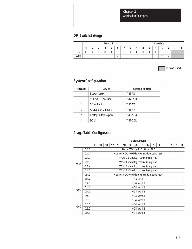
Chapter 8Application Examples
8–5
DIP Switch Settings
Switch 1 Switch 2
1 2 3 4 5 6 7 8 1 2 3 4 5 6 7 8
ON X X X X X X X X X X X
OFF X X X
= Not used
System Configuration
Amount Device Catalog Number
1 Power Supply 1746-P2
1 SLC 5/01 Processor 1747-L511
1 7-Slot Rack 1746-A7
2 Analog Input, 4 point 1746-NI4
2 Analog Output, 4 point 1746-NO4I
1 DCM 1747-DCM
Image Table Configuration
Output Image
15 14 13 12 11 10 9 8 7 6 5 4 3 2 1 0
O:1.0 Status Word to PLC-5 from SLC
O:1.1 Counter ACC word denotes module being read
O:1.2 Word 0 of analog module being read
O:1.3 Word 1 of analog module being readDCM
O:1.4 Word 2 of analog module being read
O:1.5 Word 3 of analog module being read
O:1.6 Counter ACC word denotes module being read
O:1.7 Not used
O:4.0 NO4I word 0
OO:4.1 NO4I word 1
NO4IO:4.2 NO4I word 2
O:4.3 NO4I word 3
O:5.0 NO4I word 0
OO:5.1 NO4I word 1
NO4IO:5.2 NO4I word 2
O:5.3 NO4I word 3
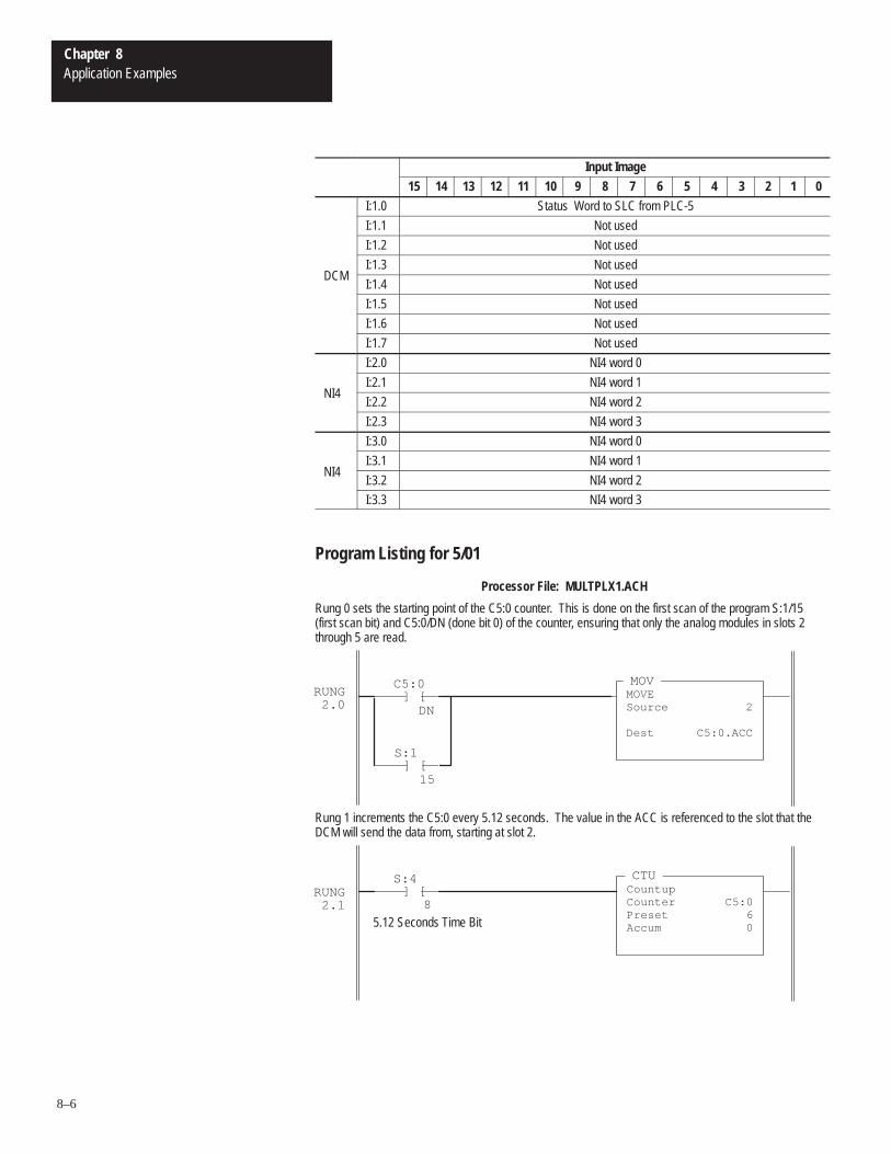
Chapter 8Application Examples
8–6
Input Image
15 14 13 12 11 10 9 8 7 6 5 4 3 2 1 0
I:1.0 Status Word to SLC from PLC-5
I:1.1 Not used
I:1.2 Not used
I:1.3 Not usedDCM
I:1.4 Not used
I:1.5 Not used
I:1.6 Not used
I:1.7 Not used
I:2.0 NI4 word 0
I:2.1 NI4 word 1NI4
I:2.2 NI4 word 2
I:2.3 NI4 word 3
I:3.0 NI4 word 0
I:3.1 NI4 word 1NI4
I:3.2 NI4 word 2
I:3.3 NI4 word 3
Program Listing for 5/01
Processor File: MULTPLX1.ACH
Rung 0 sets the starting point of the C5:0 counter. This is done on the first scan of the program S:1/15(first scan bit) and C5:0/DN (done bit 0) of the counter, ensuring that only the analog modules in slots 2through 5 are read.
] [C5:0
DN
RUNG2.0
] [S:1
15
MOVMOVESource 2
Dest C5:0.ACC
Rung 1 increments the C5:0 every 5.12 seconds. The value in the ACC is referenced to the slot that theDCM will send the data from, starting at slot 2.
] [S:4
RUNG2.1
CTUCountupCounter C5:0Preset 6Accum 0
8
5.12 Seconds Time Bit
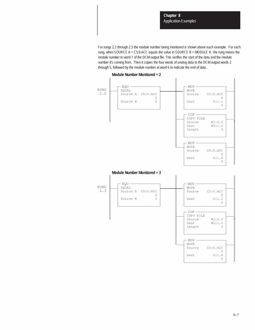
Chapter 8Application Examples
8–7
RUNG2.2
EQUEQUALSource A C5:0.ACC
0Source B 2
MOVMOVESource C5:0.ACC
0Dest 0:1.1
0
COPCOPY FILESource #I:2.0Dest #0:1.2Length 4
MOVMOVESource C5:0.ACC
0Dest 0:1.6
0
Module Number Monitored = 2
For rungs 2.2 through 2.5 the module number being monitored is shown above each example. For eachrung, when SOURCE A = C5:0.ACC equals the value in SOURCE B = MODULE #, the rung moves themodule number to word 1 of the DCM output file. This verifies the start of the data and the modulenumber it’s coming from. Then it copies the four words of analog data to the DCM output words 2through 5, followed by the module number at word 6 to indicate the end of data.
RUNG2.3
EQUEQUALSource A C5:0.ACC
0Source B 3
MOVMOVESource C5:0.ACC
0Dest 0:1.1
0
COPCOPY FILESource #I:3.0Dest #0:1.2Length 4
MOVMOVESource C5:0.ACC
0Dest 0:1.6
0
Module Number Monitored = 3
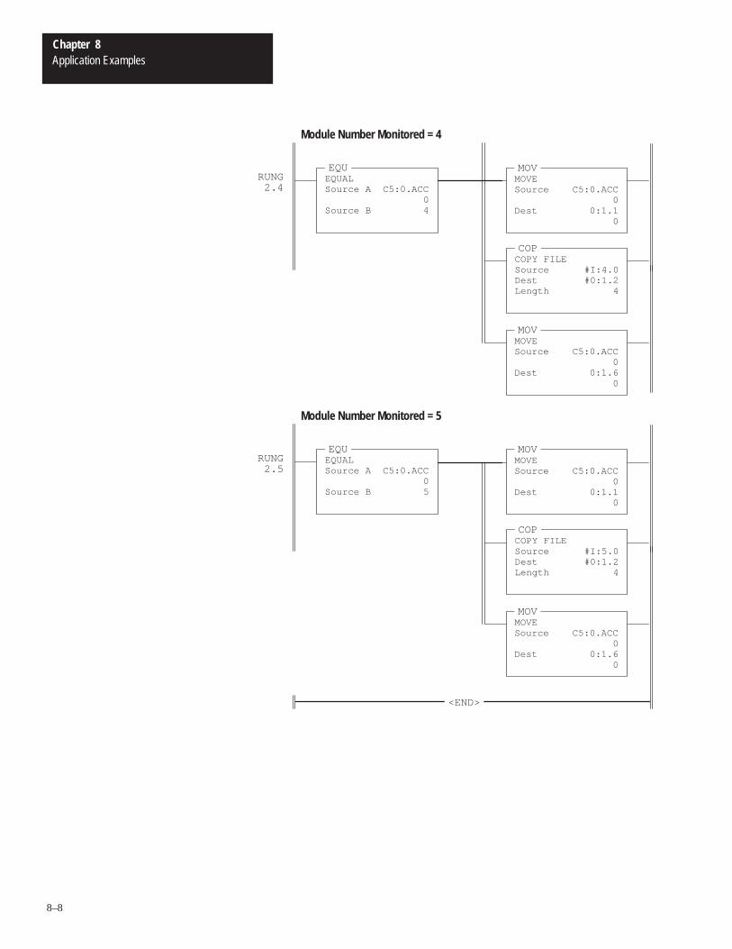
Chapter 8Application Examples
8–8
RUNG2.4
EQUEQUALSource A C5:0.ACC
0Source B 4
MOVMOVESource C5:0.ACC
0Dest 0:1.1
0
COPCOPY FILESource #I:4.0Dest #0:1.2Length 4
MOVMOVESource C5:0.ACC
0Dest 0:1.6
0
Module Number Monitored = 4
RUNG2.5
EQUEQUALSource A C5:0.ACC
0Source B 5
MOVMOVESource C5:0.ACC
0Dest 0:1.1
0
COPCOPY FILESource #I:5.0Dest #0:1.2Length 4
MOVMOVESource C5:0.ACC
0Dest 0:1.6
0
<END>
Module Number Monitored = 5
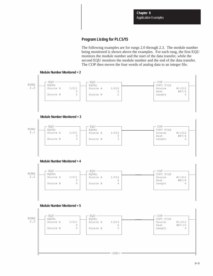
Chapter 8Application Examples
8–9
Program Listing for PLC5/15
The following examples are for rungs 2.0 through 2.3. The module numberbeing monitored is shown above the examples. For each rung, the first EQUmonitors the module number and the start of the data transfer, while thesecond EQU monitors the module number and the end of the data transfer.The COP then moves the four words of analog data to an integer file.
RUNG2.0
EQUEQUALSource A I:011
0Source B 2
COPCOPY FILESource #I:012Dest #N7:0Length 4
EQUEQUALSource A I:016
0Source B 2
Module Number Monitored = 2
RUNG2.1
EQUEQUALSource A I:011
0Source B 3
COPCOPY FILESource #I:012Dest #N7:4Length 4
EQUEQUALSource A I:016
0Source B 3
Module Number Monitored = 3
RUNG2.2
EQUEQUALSource A I:011
0Source B 4
COPCOPY FILESource #I:012Dest #N7:8Length 4
EQUEQUALSource A I:016
0Source B 4
Module Number Monitored = 4
RUNG2.3
EQUEQUALSource A I:011
0Source B 5
COPCOPY FILESource #I:012Dest #N7:12Length 4
EQUEQUALSource A I:016
0Source B 5
<END>
Module Number Monitored = 5

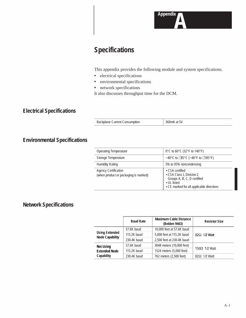
AAppendix
A–1
Specifications
This appendix provides the following module and system specifications.
• electrical specifications• environmental specifications• network specificationsIt also discusses throughput time for the DCM.
Backplane Current Consumption 360mA at 5V
Operating Temperature 0°C to 60°C (32°F to 140°F)
Storage Temperature −40°C to +85°C (−40°F to +185°F)
Humidity Rating 5% to 95% noncondensing
Agency Certification(when product or packaging is marked)
• CSA certified• CSA Class I, Division 2
Groups A, B, C, D certified• UL listed• CE marked for all applicable directives
Baud RateMaximum Cable Distance
(Belden 9463) Resistor Size
Us n xten e57.6K baud 10,000 feet at 57.6K baud
Using Extendedo e apab l t
115.2K baud 5,000 feet at 115.2K baud 82� 1/2 WattNode Capability
230.4K baud 2,500 feet at 230.4K baud82� 1/2 Watt
Not Using 57.6K baud 3048 meters (10,000 feet)1 � 1Not Using
Extended Nodeapab l t
115.2K baud 1524 meters (5,000 feet)150� 1/2 Watt
Extended NodeCapability 230.4K baud 762 meters (2,500 feet) 82� 1/2 Watt
Electrical Specifications
Environmental Specifications
Network Specifications
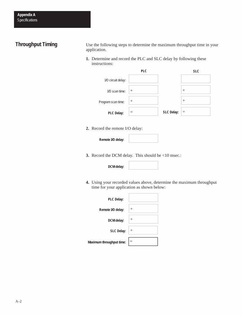
Appendix ASpecifications
A–2
Use the following steps to determine the maximum throughput time in yourapplication.
1. Determine and record the PLC and SLC delay by following theseinstructions:
I/O circuit delay:
I/O scan time:
PLC SLC
Program scan time:
PLC Delay:
+
+
SLC Delay:=
+
+
=
2. Record the remote I/O delay:
Remote I/O delay:
3. Record the DCM delay. This should be <10 msec.:
DCM delay:
4. Using your recorded values above, determine the maximum throughputtime for your application as shown below:
DCM delay:
PLC Delay:
+Remote I/O delay:
SLC Delay:
=
+
+
Maximum throughput time:
Throughput Timing
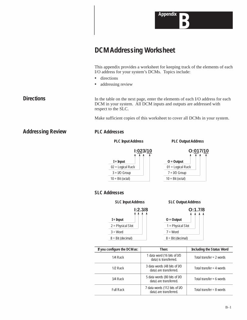
BAppendix
B–1
DCM Addressing Worksheet
This appendix provides a worksheet for keeping track of the elements of eachI/O address for your system’s DCMs. Topics include:
• directions• addressing review
In the table on the next page, enter the elements of each I/O address for eachDCM in your system. All DCM inputs and outputs are addressed withrespect to the SLC.
Make sufficient copies of this worksheet to cover all DCMs in your system.
PLC Addresses
I = Input
O:017/10I:023/10
02 = Logical Rack
3 = I/O Group
10 = Bit (octal)
O = Output
01 = Logical Rack
7 = I/O Group
10 = Bit (octal)
PLC Input Address PLC Output Address
SLC Addresses
I = Input
O:1.7/8I:2.3/8
2 = Physical Slot
3 = Word
8 = Bit (decimal)
O = Output
1 = Physical Slot
7 = Word
8 = Bit (decimal)
SLC Input Address SLC Output Address
If you configure the DCM as: Then: Including the Status Word
1/4 Rack 1 data word (16 bits of I/Odata) is transferred.
Total transfer = 2 words
1/2 Rack 3 data words (48 bits of I/Odata) are transferred.
Total transfer = 4 words
3/4 Rack 5 data words (80 bits of I/Odata) are transferred.
Total transfer = 6 words
Full Rack 7 data words (112 bits of I/Odata) are transferred.
Total transfer = 8 words
Directions
Addressing Review
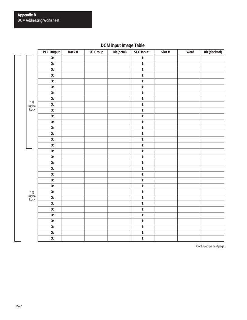
Appendix BDCM Addressing Worksheet
B–2
DCM Input Image TablePLC Output Rack # SLC Input
O:
O:
O:
1/4LogicalRack
1/2LogicalRack
O:
O:
O:
O:
O:
O:
O:
O:
O:
O:
O:
O:
O:
O:
O:
O:
O:
O:
O:
O:
O:
O:
O:
O:
O:
O:
O:
O:
O:
I:
I:
I:
I:
I:
I:
I:
I:
I:
I:
I:
I:
I:
I:
I:
I:
I:
I:
I:
I:
I:
I:
I:
I:
I:
I:
I:
I:
I:
I:
I:
I:
I/O Group Bit (octal) Slot # Word Bit (decimal)
Continued on next page.
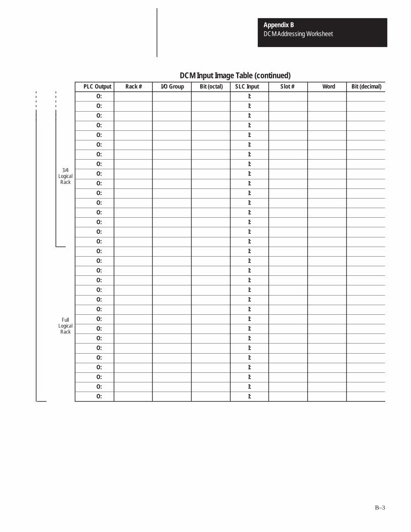
Appendix BDCM Addressing Worksheet
B–3
DCM Input Image Table (continued)PLC Output Rack # SLC Input
O:
O:
O:
3/4LogicalRack
FullLogicalRack
O:
O:
O:
O:
O:
O:
O:
O:
O:
O:
O:
O:
O:
O:
O:
O:
O:
O:
O:
O:
O:
O:
O:
O:
O:
O:
O:
O:
O:
I:
I:
I:
I:
I:
I:
I:
I:
I:
I:
I:
I:
I:
I:
I:
I:
I:
I:
I:
I:
I:
I:
I:
I:
I:
I:
I:
I:
I:
I:
I:
I:
I/O Group Bit (octal) Slot # Word Bit (decimal)
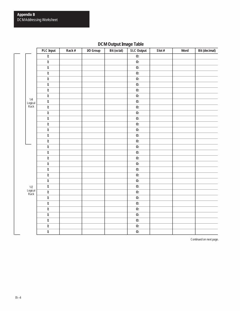
Appendix BDCM Addressing Worksheet
B–4
DCM Output Image TablePLC Input Rack # SLC Output
O:
O:
O:
1/4LogicalRack
1/2LogicalRack
O:
O:
O:
O:
O:
O:
O:
O:
O:
O:
O:
O:
O:
O:
O:
O:
O:
O:
O:
O:
O:
O:
O:
O:
O:
O:
O:
O:
O:
I:
I:
I:
I:
I:
I:
I:
I:
I:
I:
I:
I:
I:
I:
I:
I:
I:
I:
I:
I:
I:
I:
I:
I:
I:
I:
I:
I:
I:
I:
I:
I:
I/O Group Bit (octal) Slot # Word Bit (decimal)
Continued on next page.

Appendix BDCM Addressing Worksheet
B–5
DCM Output Image Table (continued)PLC Input Rack # SLC Output
O:
O:
O:
3/4LogicalRack
FullLogicalRack
O:
O:
O:
O:
O:
O:
O:
O:
O:
O:
O:
O:
O:
O:
O:
O:
O:
O:
O:
O:
O:
O:
O:
O:
O:
O:
O:
O:
O:
I:
I:
I:
I:
I:
I:
I:
I:
I:
I:
I:
I:
I:
I:
I:
I:
I:
I:
I:
I:
I:
I:
I:
I:
I:
I:
I:
I:
I:
I:
I:
I:
I/O Group Bit (octal) Slot # Word Bit (decimal)

Direct Communication ModuleIndex
User Manual
I–1
Numbers
1/2 rack, 2–3, 4–6
1/4 rack, 2–3, 4–6
3/4 rack, 2–3, 4–6
A
adapter, 1–4extended node capability, 1–4interaction with scanners, 1–2on RIO link as slave device, 1–2
adapter image, 1–4
addressing ladder logic instructions, 3–1PLC addresses, 3–2SLC addresses, 3–3
addressing worksheet directions, B–1
Allen-Bradley, P–4contacting for assistance, P–4
application examplesbasic DCM, 8–1programming, 6–2supplementary DCM, 8–4using status word bits, 6–7
applications using status word bits, 6–7Data Invalid bit in the SLC Status Word,
6–7Logical OR bit, 6–10Program/Test/Fault Mode bit in the RIO
scanner status word, 6–7User Status Flag bit in the SLC Status
Word, 6–8
available scanners, 2–2
B
backplane current consumption, A–1
basic DCM application example, 8–1
baud rateresistor, 2–4specifications, 2–4, 5–3, A–1
Belden 9463 cable, maximum distance, 2–4,5–3, A–1
bit address, 3–2, 3–3
C
cable distance, maximum, 2–4, 5–3, A–1
cable tie slots, 1–1, 5–2
CE certification, 5–1
chassis slotcard guides, 5–2Card Slot Filler, 5–2
Clear On Fault (SW2-3), 4–7
COMM LED, 1–1
Communication Error bit, 6–5
configuring the module, 4–1
contacting Allen-Bradley for assistance, P–4
contents of manual, P–2
D
Data Invalid bit, 6–7
Data Rate (SW2-1 and SW2-2), 4–7
DCM features, 1–1hardware, 1–1
cable tie slots, 1–1COMM LED, 1–1DIP switches, 1–1FAULT LED, 1–1front, side and door labels, 1–1self-locking tabs, 1–1
DCM Initialization bit, 6–5
DCM installation and wiring, 5–1
DCM Output Data Invalid bit, 6–6
DCM overview, 1–1
DCM status word bit examination (decimal)DCM output data invalid bit, 6–6User Status Flag, 6–6
definitions, P–3
determining maximum throughput time, A–2
DIP switches, 1–1, 4–1switch 1 settings, 4–2
I/O Group (SW1-7 and SW1-8), 4–2Rack Addresses (SW1-1 through
SW1-6), 4–3switch 2 settings, 4–6
Clear On Fault (SW2-3), 4–7Data Rate (SW2-1 and SW2-2), 4–7Last Rack (SW2-4), 4–6Module Rack Size (SW2-5 and SW2-6),
4–6
door label, 1–1
User ManualDirect Communication ModuleIndex
I–2
E
electrical specifications, A–1
EMC Directive, 5–1
environmental specifications, A–1
equipment needed, 2–1
errors, troubleshooting, 7–2
European Union Directives Compliance, 5–1
Examine If Open instruction (XIO), 6–7, 6–10
examplesbasic DCM application, 8–1programming, 6–2status word bit application, 6–7supplementary DCM application, 8–4
extended node capability, 1–4of scanners and adapters, 1–4of the DCM, 1–4specifications, 2–4, 5–3, A–1
F
FAULT LED, 1–1
flashing LED, 7–2
front label, 1–1
full rack, 2–3, 4–6
G
getting started, 2–1procedure, 2–2
glossary terms, P–3
green LED, troubleshooting using, 7–2
H
hardware features, 1–1cable tie slots, 1–1COMM LED, 1–1DIP switches, 1–1FAULT LED, 1–1front, side and door labels, 1–1RIO link connector, 1–1self-locking tabs, 1–1
hardware overview, 1–1hardware features, 1–1
Hold Last State, in status word applications,6–7
humidity rating, A–1
I
I/O Group (SW1-7 and SW1-8), 4–2
I/O group address, 3–2
I/O image tables, 3–4
image division configuration, scanner, 1–5
image mapping, 3–5
inserting the cable tie, 5–2
installation, getting started, 2–1
installing the module, 5–1
L
labels, front, side and door, 1–1
ladder logic instructions, addressing, 3–1
Last Rack (SW2-4), 4–6
LEDs, 7–1blinking, 7–1COMM (green), 7–2FAULT (red), 7–1steady state, 7–1troubleshooting using, 7–1
link wiring, 5–2
logical group, 1–4
Logical OR bit, 6–5, 6–6, 6–10
logical rack, 1–4
logical specifications, 1–2
M
manuals, related, P–2
Module Rack Size (SW2-5 and SW2-6), 4–6
module release, 5–2
N
network specifications, A–1
network wiring, 5–3
P
physical specifications, 1–2
PLC addresses, 3–2bit address, 3–2I/O group address, 3–2rack address, 3–2
Direct Communication ModuleIndex
User Manual
I–3
PLC scanner output image, 3–5, 3–6
power up, system, 2–4
Program/Test/Fault Mode bit, 6–5, 6–6, 6–7
programming examples, 6–2physical input into both PLC and SLC –
physical output from SLC, 6–3physical input into first SLC – physical
output from second SLC, 6–4physical input into PLC – physical output
from SLC, 6–2physical input into SLC – physical output
from PLC, 6–3
programming overview, 6–1
publications, related, P–2
R
rack address, 3–2
Rack Address (SW1-1 through SW1-6), 4–3
rack size1/2 rack, 2–3, 4–61/4 rack, 2–3, 4–63/4 rack, 2–3, 4–6full rack, 2–3, 4–6number of data words transferred
according to, 2–3
recording I/O addresses, B–1
red LED, troubleshooting using, 7–1
remote I/Oadapter, 1–2communications link, 1–2link connector, 1–1
removing the module, 5–2
required tools and equipment, 2–1
resistor baud rate, 2–4
RIO adapter, 1–2
RIO communications link, 1–2
RIO link connector, 1–1
RIO scanner status word bit examination(decimal), 6–5
Communications Error bit, 6–5DCM initialization bit, 6–5Logical OR of other status word bits, 6–5Program/Test/Fault Mode bit, 6–5
RIO scanners, 2–2
S
scanner, image division, 1–4logical groups, 1–4logical racks, 1–4
scanner image division, 1–4configuration example, 1–5
scannersnumber of physical and logical devices
supported by, 2–3selection, 2–2
self-locking tabs, 1–1
setting the DIP switches, 4–1
side label, 1–1
SLC addresses, 3–3bit address, 3–3slot address, 3–3word address, 3–3
SLC input image, 3–5, 3–6
slot address, 3–3
specifications, A–1cable distance, 2–4, 5–3, A–1electrical, A–1environmental, A–1network, A–1resistor size, 2–4, 5–3, A–1temperature and humidity, A–1
start-up instructions, 2–1
status words, 1–6, 6–5about the, 1–6DCM status word bit examination (octal),
6–6RIO scanner status word bit examination
(decimal), 6–5
supplementary DCM application example,8–4
SW1-1 through SW1-6, DIP switch, RackAddress, 4–3
SW1-7 and SW1-8, DIP switch, I/O Group,4–2
SW2-1 and SW2-2, DIP switch, Data Rate,4–7
SW2-3, DIP switch, Clear On Fault, 4–7
SW2-4, DIP switch, Last Rack, 4–6
User ManualDirect Communication ModuleIndex
I–4
SW2-5 and SW2-6, DIP switch, Module RackSize, 4–6
system overview, 1–2data exchange between a PLC and SLC,
1–2logical rack, 1–2remote I/O analysis, 1–2system configuration restriction factors,
1–2
system powerup, 2–4
T
temperature specifications, A–1operating, A–1storage, A–1
terminating resistor, size of, 5–3
terms, P–3
throughput timing, A–2
tools needed, 2–1
troubleshooting, 7–1contacting Allen-Bradley, P–4using the COMM LED (green), 7–2using the FAULT LED (red), 7–1
U
User Status Flag bit, 6–6, 6–8
W
wiring the network, 5–3
word address, 3–3
worksheets, B–1


Publication 1747-6.8 – June 1996
Allen-Bradley, a Rockwell Automation Business, has been helping its customers improveproductivity and quality for more than 90 years. We design, manufacture and support a broadrange of automation products worldwide. They include logic processors, power and motioncontrol devices, operator interfaces, sensors and a variety of software. Rockwell is one of theworld’s leading technology companies.
Worldwide representation.Argentina • Australia • Austria • Bahrain • Belgium • Brazil • Bulgaria • Canada • Chile • China, PRC • Colombia • Costa Rica • Croatia • Cyprus • Czech Republic • Denmark •Ecuador • Egypt • El Salvador • Finland • France • Germany • Greece • Guatemala • Honduras • Hong Kong • Hungary • Iceland • India • Indonesia • Ireland • Israel • Italy •Jamaica • Japan • Jordan • Korea • Kuwait • Lebanon • Malaysia • Mexico • Netherlands • New Zealand • Norway • Pakistan • Peru • Philippines • Poland • Portugal • PuertoRico • Qatar • Romania • Russia–CIS • Saudi Arabia • Singapore • Slovakia • Slovenia • South Africa, Republic • Spain • Sweden • Switzerland • Taiwan • Thailand • Turkey •United Arab Emirates • United Kingdom • United States • Uruguay • Venezuela • Yugoslavia
Allen-Bradley Headquarters, 1201 South Second Street, Milwaukee, WI 53204 USA, Tel: (1) 414 382-2000 Fax: (1) 414 382-4444
Publication 1747-6.8 – June 1996Supersedes Publication 1747-NM007 – September 1993
40072-032-01(A)Copyright 1996 Allen-Bradley Company, Inc. Printed in USA