Embed Size (px)
Citation preview
Article Designation: Refereed JTATM Volume 5, Issue 2,Summer 2006
1
Volume 5, Issue 2, Summer2006
Predicting Initial Pressure Drop of Fibrous Filter Media –
Typical Models and Recent Improvements
Peter K. Herman 1, Martin J. Lehmann 2, Yogeshwar K. Velu3
Fleetguard Inc 1200 Fleetguard Rd, Cookeville, TN 38506
[email protected] [email protected] (now at Mann+Hummel GmbH)
ABSTRACT
Initial pressure drop, along with efficiency and capacity, is one of the important performance parameters of a fibrous filter. In moving towards “Analysis-Led Design” of filtration products, a realistic prediction of initial pressure drop based on media physical parameters is a necessary first step.
We will present existing models, such as the 2D Kuwabara and the 3D cellular approach, and discuss their limitations in predicting initial pressure drop of fibrous filter media, which have pushed us towards a numerical modeling (CFD) approach. In order to optimize the inner fiber structure for a specific application, simple and rapid simulations are required. Therefore a 2D approach, which can run on a standard PC workstation, is favored over sophisticated 3D fiber models, running on parallel computers.
As the fiber structure is not truly random, a literature survey of various 2D approaches to model disarrangement or random fiber structures will be presented. However, fully random structures still over-predict the pressure drop by 120 % to 200 %, compared to measurements on some of our important filter media grades. Therefore we will present some of the results of a Technology Development for Six Sigma (TDFSS) project, and our approach of modeling fibrous filters by creating “partial-random” structures. We will illustrate our rapid and highly automated method combining MATLAB and the CFD program FLUENT/GAMBIT to predict realistic initial pressure drop values. The much-improved agreement between CFD predictions and measurements for a wide variety of different filter media will be shown and discussed.
Keywords: Filtration, CFD, 2D Kuwabara, 3D cellular approach
Introduction Usually the pressure drop ∆p of a fibrous filter media is predicted based on the flow resistance of single fibers. In the simplest case of a homogeneous media consisting of
fibers monodisperse in diameter, the initial pressure drop is calculated by
F
DD
cv
zp
42
2
παρ
=∆
(Eq. 1)
Article Designation: Refereed JTATM Volume 5, Issue 2,Summer 2006
2
The drag coefficient cD is a function of the local flow field around a single fiber, described by the hydrodynamic factor H:
( )απ
HcD Re
8= (Eq. 2)
According to Kirsch and Fuchs (1967) the analytical solution of Kuwabara (1959) agrees best for 0.005 < a < 0.2, Re < 5 and Kn < 0.001 with experimental measurements:
( )44
3ln
21 2α
ααα +−+=KuwabaraH (Eq. 3)
This approach to predict pressure drop is appropriate for a medium with a constant packing density and a regular and parallel fiber arrangement, aligned perpendicular to flow direction. Technical media, however, consists of multiple zones of different packing density. Furthermore the production process causes some variations in the local packing density. The non-realistic assumptions cause the Kuwabara model to greatly over-predict (5x has been observed) the pressure drop for many “real-world” filtration media. To account for this inhomogeneous fiber arrangement of technical filter media, usually a cellular model is applied (Schweers, 1993). Based on the assumption of the fiber distribution within the media, the local packing density of each cell is determined. Assuming a regular fiber arrangement within a cell, the pressure drop of each cell and by summation the pressure drop of a filter medium is calculated. Typically the cell size should be chosen such that not more than four fibers fall within one cell, as Mölter and Fissan (1997) numerically and Brown (1994) analytically showed for 2D models. The cellular model, however, does not allow correlating pressure drop to variations in the micro arrangement of fibers, as up to four fibers can be packed into one cell. But according to the work of Günter (1998) local fiber disarrangement influences pressure drop, and according to measurements of Kanaoka et al. (1984) and Schweers (1993),
strongly effects particle collection efficiency compared to an isolated single fiber. Therefore an approach modeling the flow around single fibers is required to account for the effect of local variations in fiber spacing on pressure drop and collection efficiency.
Modern CFD programs are the tool of choice to investigate the flow through structures built of single fibers, as they are capable of dealing with various kinds of complex fiber arrangements. Recent results (Mironescu et al., 2000, Lehmann and Herman, 2005a, Tronville and Rivers, 2005) demonstrated that generating random fiber structures improves pressure drop predictions, but might still be up to 200% higher than measured for a real filter of similar media properties. Therefore we introduced partial-random structures (Lehmann and Herman, 2005b), allowing us to account for the local inhomogeneity of the fiber structure. Before applying this new approach to various kinds of real filter media, we will briefly present our new highly automated method of generating different kinds of fiber structures.
Method to generate and model fiber structures The following approach to generate (random) fiber structures is restricted to 2D cross sections of filter media, due to computer and meshing limitations. This 2D simplification is largely justified because in the production process, the fibers are randomly laid down in layers that are predominantly perpendicular to the direction of the face velocity (Schweers, 1993; Mölter and Fissan, 1995, 1997; Vaughan and Brown, 1996). For technical media the arrangement of fibers over the cross section is irregular and might be considered random. Furthermore, the fiber size distribution and the media packing density (or alternatively void volume) must be taken into account. MATLAB 6.5 was chosen to generate the positions of the fibers distributed over the cross section, as it easily generates random numbers to place fibers and also has an implemented log-normal random number generator. The la tter feature facilitates the
Article Designation: Refereed JTATM Volume 5, Issue 2,Summer 2006
3
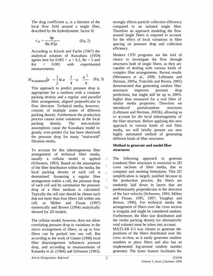
quick and simple assignment of size to the fibers, as the fiber size distribution for typical technical media (melt-blown, microglass, melt-spun, etc.) have been found to closely obey a log-normal distribution function. This relationship is shown for SEM measurements on a typical microglass media filter and the subsequent “re-creation” of the fiber size distribution by the MATLAB program illustrated in Figure 1. The re-created log-normal fiber size
distribution closely follows the measurements, but a few “oversize” and “undersize” fibers are created that are never observed in the actual SEM measurements. Therefore, truncation limits were also implemented to discard any fibers that fall outside of a measured range. This minor modification to perfectly log-normal distribution was found to cause negligible effect on predicted flow restriction for typical filter media definitions.
Matlab Fiber Generator Program: Cumulative Fiber Size Distribution vs. SEM Measurements for Microglass
0%
10%
20%
30%
40%
50%
60%
70%
80%
90%
100%
0 2 4 6 8 10
Fiber size (micron)%
Les
s th
an s
ize
SEM data
Matlab Fiber Generator
Figure 1: Two comparative probability plots for fiber diameter (of microglass, in this
case) shows the superiority of log-normal distribution function. Second graph shows the measured vs. Matlab program re-created log-normal fiber diameter cumulative distribution
Additionally, the MATLAB programming environment enables quick generation of multi-layer gradient-density media structures with their varying fiber size distribution and packing density (in each layer). Furthermore, the programming language enables the very rapid generation of an output journal file containing all the fiber structure data that can be easy imported into GAMBIT for rapid meshing and exported to FLUENT for subsequent laminar flow simulation and pressure drop prediction. It is important to note that airflow through typical filter structures is not completely in the continuum regime, and exhibits “slip” at boundary walls. The effect cannot be ignored for Knudsen numbers >0.1 (corresponding to fiber diameter ~0.6 micron), and slip-boundary modifications are desirable between 0.001<Kn<0.1 (Graham 2002, Gad-el-Hak 1999). However, for the cases reported herein with Kn ranging from 0.004-0.02, the effect was neglected to simplify and speed the modeling process. This semi-automatic
process (Figure 2) enables entire modeling procedure (including generation, meshing, and running model to converged solution) of typical media structures in less than one hour on a single-processor Pentium 4 PC.
Our MATLAB program also provides features for generating staggered fiber (regular/periodic repeating) and semi-random fiber structures. In the latter case we initially place a predefined fraction of fibers randomly over the layer’s cross section and then place the remaining fraction in close proximity to randomly selected, but already-existing fibers. In this way we obtain a realistic “clumpy” random fiber structure with varying local packing densities. As a naming convention, we use “LPDVxx” as abbreviation for “Local Packing Density Variation” and xx indicating the percent of fibers placed in close proximity to previous placed fibers. In this paper we refer to them by the general term of “partial-random” structure. The fluid flow through these partial-random structures becomes
Article Designation: Refereed JTATM Volume 5, Issue 2,Summer 2006
4
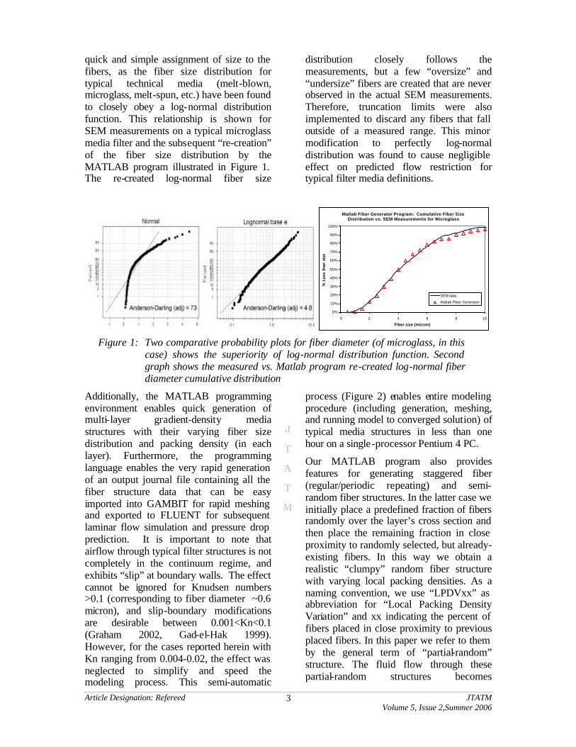
increasingly “channeled”, whereby the bulk of flow convects through large gaps between fiber “super-clusters”, although some small fraction of flow still continues to creep
through the interior gaps of fiber clusters, which may be an important phenomenon in retaining filtration efficiency for small particles.
Figure 2: Semi-automatic process of generating random fiber structures 1. MATLAB – placing fibers of size according to a log-norm size distribution, 2. GAMBIT – importing journal file of fiber geometry, meshing, 3. FLUENT – CFD simulation, here: average fiber diameter 15 µm and 3 µm, lubricant oil, face velocity 0.0025 m/s
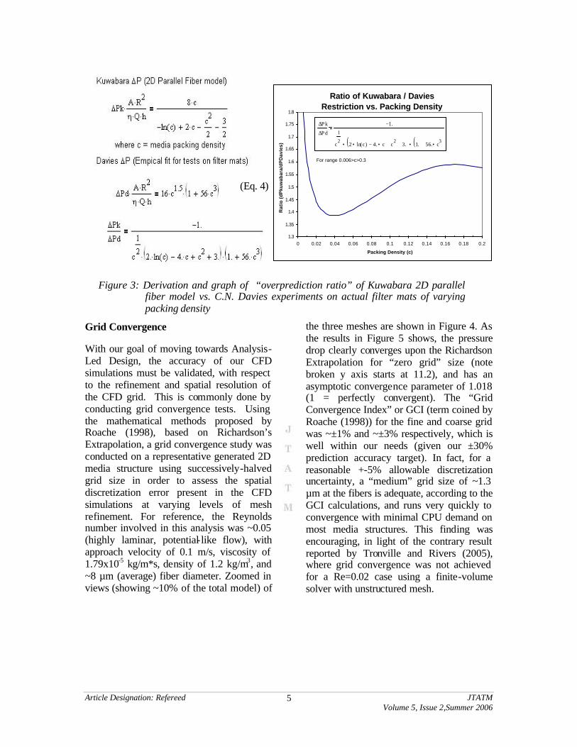
2D to 3D Empirical Correction However, even when accounting for fiber size distribution and allowing random placement, the 2D (parallel fiber) simplification inherently over-predicts pressure drop due to fiber-crossing and shadowing effects. In an effort to correct for this known effect, we apply an empirical correction to the 2D “Kuwabara-like” CFD
predictions based on the correlation between C.N. Davies (measurements on widely-varying filter-pad structures) vs. Kuwabara (2D parallel staggered fiber analytical model) as a function of packing density as shown in Figure 3 and derived in Equation 4. Note that this ratio relationship is only a function of packing density so our log-normal distribution of fiber diameter does not affect the ratio.
Article Designation: Refereed JTATM Volume 5, Issue 2,Summer 2006
5
Ratio of Kuwabara / Davies Restriction vs. Packing Density
1.3
1.35
1.4
1.45
1.5
1.55
1.6
1.65
1.7
1.75
1.8
0 0.02 0.04 0.06 0.08 0.1 0.12 0.14 0.16 0.18 0.2
Packing Density (c)
Rat
io (
dP
kuw
abar
a/d
PD
avie
s)
∆P k
∆P d
1.−
c
1
22 ln c( )• 4. c•− c
2+ 3.+( ) 1. 56. c
3•+( )••
For range 0.006>c>0.3
Figure 3: Derivation and graph of “overprediction ratio” of Kuwabara 2D parallel fiber model vs. C.N. Davies experiments on actual filter mats of varying packing density
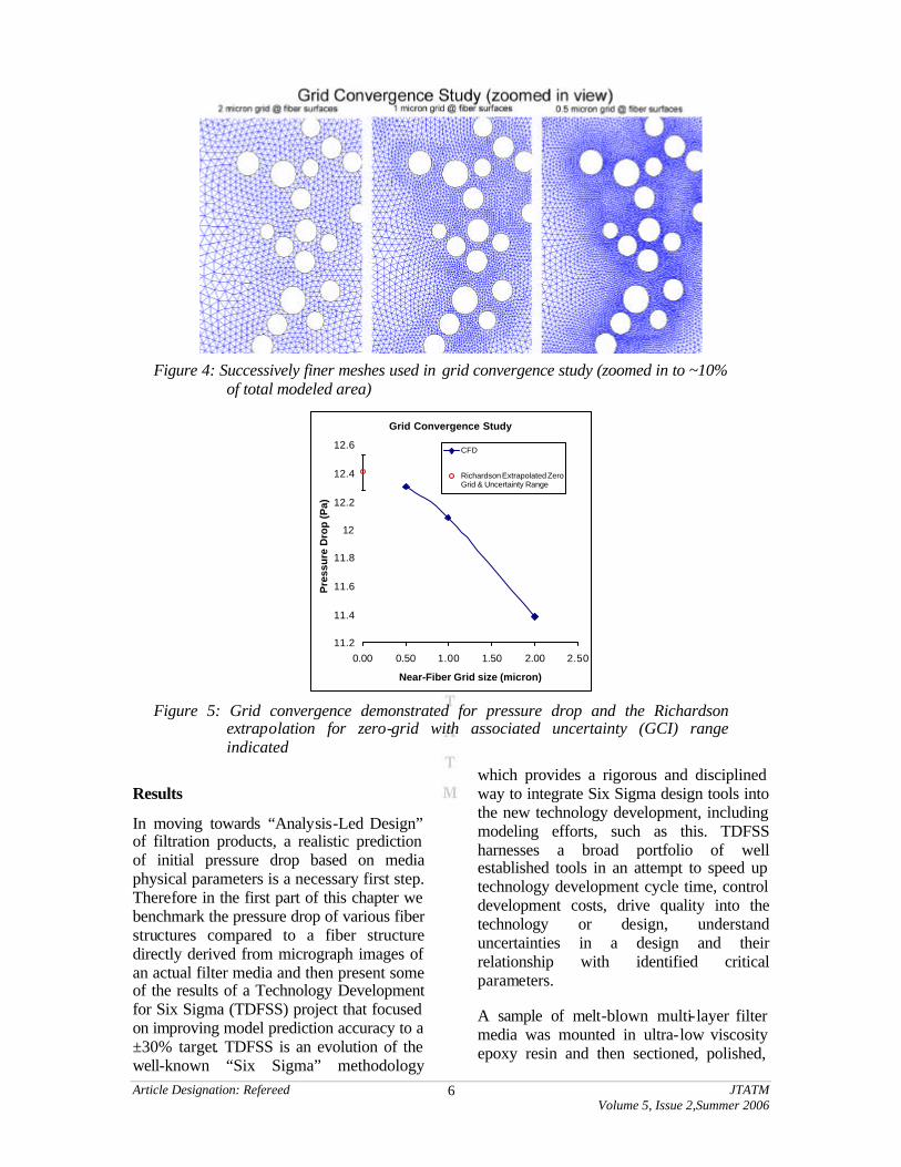
Grid Convergence With our goal of moving towards Analysis-Led Design, the accuracy of our CFD simulations must be validated, with respect to the refinement and spatial resolution of the CFD grid. This is commonly done by conducting grid convergence tests. Using the mathematical methods proposed by Roache (1998), based on Richardson’s Extrapolation, a grid convergence study was conducted on a representative generated 2D media structure using successively-halved grid size in order to assess the spatial discretization error present in the CFD simulations at varying levels of mesh refinement. For reference, the Reynolds number involved in this analysis was ~0.05 (highly laminar, potential-like flow), with approach velocity of 0.1 m/s, viscosity of 1.79x10⁻⁵ kg/m*s, density of 1.2 kg/m3, and ~8 µm (average) fiber diameter. Zoomed in views (showing ~10% of the total model) of
the three meshes are shown in Figure 4. As the results in Figure 5 shows, the pressure drop clearly converges upon the Richardson Extrapolation for “zero grid” size (note broken y axis starts at 11.2), and has an asymptotic convergence parameter of 1.018 (1 = perfectly convergent). The “Grid Convergence Index” or GCI (term coined by Roache (1998)) for the fine and coarse grid was ~±1% and ~±3% respectively, which is well within our needs (given our ±30% prediction accuracy target). In fact, for a reasonable +-5% allowable discretization uncertainty, a “medium” grid size of ~1.3 µm at the fibers is adequate, according to the GCI calculations, and runs very quickly to convergence with minimal CPU demand on most media structures. This finding was encouraging, in light of the contrary result reported by Tronville and Rivers (2005), where grid convergence was not achieved for a Re=0.02 case using a finite-volume solver with unstructured mesh.
(Eq. 4)
Article Designation: Refereed JTATM Volume 5, Issue 2,Summer 2006
6
Figure 4: Successively finer meshes used in grid convergence study (zoomed in to ~10%
of total modeled area)
Grid Convergence Study
11.2
11.4
11.6
11.8
12
12.2
12.4
12.6
0.00 0.50 1.00 1.50 2.00 2.50
Near-Fiber Grid size (micron)
Pre
ssu
re D
rop
(Pa)
CFD
Richardson Extrapolated ZeroGrid & Uncertainty Range
Figure 5: Grid convergence demonstrated for pressure drop and the Richardson
extrapolation for zero-grid with associated uncertainty (GCI) range indicated
Results
In moving towards “Analysis-Led Design” of filtration products, a realistic prediction of initial pressure drop based on media physical parameters is a necessary first step. Therefore in the first part of this chapter we benchmark the pressure drop of various fiber structures compared to a fiber structure directly derived from micrograph images of an actual filter media and then present some of the results of a Technology Development for Six Sigma (TDFSS) project that focused on improving model prediction accuracy to a ±30% target. TDFSS is an evolution of the well-known “Six Sigma” methodology
which provides a rigorous and disciplined way to integrate Six Sigma design tools into the new technology development, including modeling efforts, such as this. TDFSS harnesses a broad portfolio of well established tools in an attempt to speed up technology development cycle time, control development costs, drive quality into the technology or design, understand uncertainties in a design and their relationship with identified critical parameters.
A sample of melt-blown multi-layer filter media was mounted in ultra-low viscosity epoxy resin and then sectioned, polished,
Article Designation: Refereed JTATM Volume 5, Issue 2,Summer 2006
7
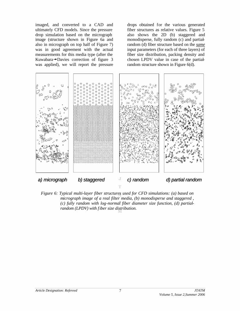
imaged, and converted to a CAD and ultimately CFD models. Since the pressure drop simulation based on the micrograph image (structure shown in Figure 6a and also in micrograph on top half of Figure 7) was in good agreement with the actual measurements for this media type (after the Kuwabara�Davies correction of figure 3 was applied), we will report the pressure
drops obtained for the various generated fiber structures as relative values. Figure 5 also shows the 2D (b) staggered and monodisperse, fully random (c) and partial-random (d) fiber structure based on the same input parameters (for each of three layers) of fiber size distribution, packing density and chosen LPDV value in case of the partial-random structure shown in Figure 6(d).
Figure 6: Typical multi-layer fiber structures used for CFD simulations: (a) based on micrograph image of a real filter media, (b) monodisperse and staggered , (c) fully random with log-normal fiber diameter size function, (d) partial-random (LPDV) with f iber size distribution.
a) micrograph b) staggered c) random d) partial randoma) micrograph b) staggered c) random d) partial random
Article Designation: Refereed JTATM Volume 5, Issue 2,Summer 2006
8
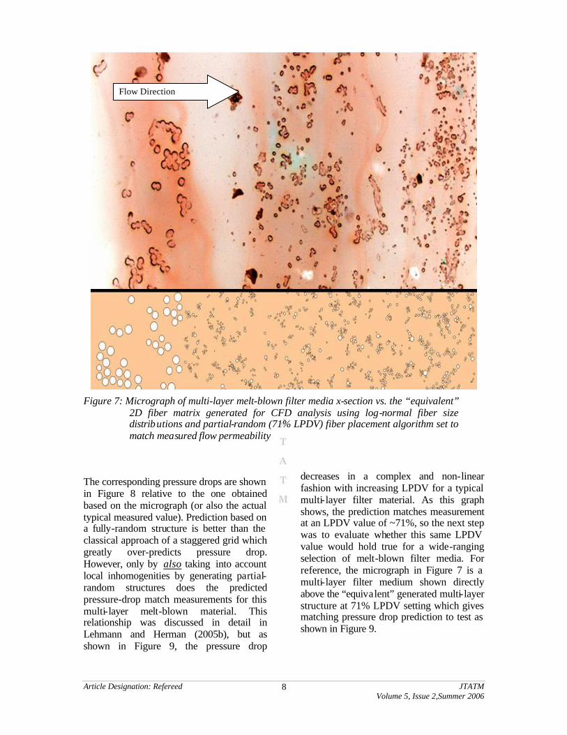
Figure 7: Micrograph of multi-layer melt-blown filter media x-section vs. the “equivalent”
2D fiber matrix generated for CFD analysis using log-normal fiber size distributions and partial-random (71% LPDV) fiber placement algorithm set to match measured flow permeability
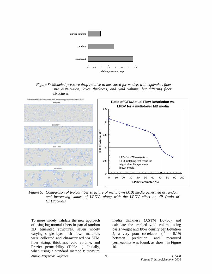
The corresponding pressure drops are shown in Figure 8 relative to the one obtained based on the micrograph (or also the actual typical measured value). Prediction based on a fully-random structure is better than the classical approach of a staggered grid which greatly over-predicts pressure drop. However, only by also taking into account local inhomogenities by generating partial-random structures does the predicted pressure-drop match measurements for this multi-layer melt-blown material. This relationship was discussed in detail in Lehmann and Herman (2005b), but as shown in Figure 9, the pressure drop
decreases in a complex and non-linear fashion with increasing LPDV for a typical multi-layer filter material. As this graph shows, the prediction matches measurement at an LPDV value of ~71%, so the next step was to evaluate whether this same LPDV value would hold true for a wide-ranging selection of melt-blown filter media. For reference, the micrograph in Figure 7 is a multi-layer filter medium shown directly above the “equivalent” generated multi-layer structure at 71% LPDV setting which gives matching pressure drop prediction to test as shown in Figure 9.
Flow Direction
Article Designation: Refereed JTATM Volume 5, Issue 2,Summer 2006
9
0 0.5 1 1.5 2 2.5 3 3.5
staggered
random
partial-random
relative pressure drop
Figure 8: Modeled pressure drop relative to measured for models with equivalent fiber size distribution, layer thickness, and void volume, but differing fiber structures
Ratio of CFD/Actual Flow Restriction vs. LPDV for a multi-layer MB media
0
0.5
1
1.5
2
2.5
0 10 20 30 40 50 60 70 80 90 100
LPDV Parameter (%)
CF
D d
P/A
ctu
al d
P
LPDV of ~71% results in CFD matching test result for a typical multi-layer melt-blown media
Figure 9: Comparison of typical fiber structure of meltblown (MB) media generated at random and increasing values of LPDV, along with the LPDV effect on dP (ratio of CFD/actual)
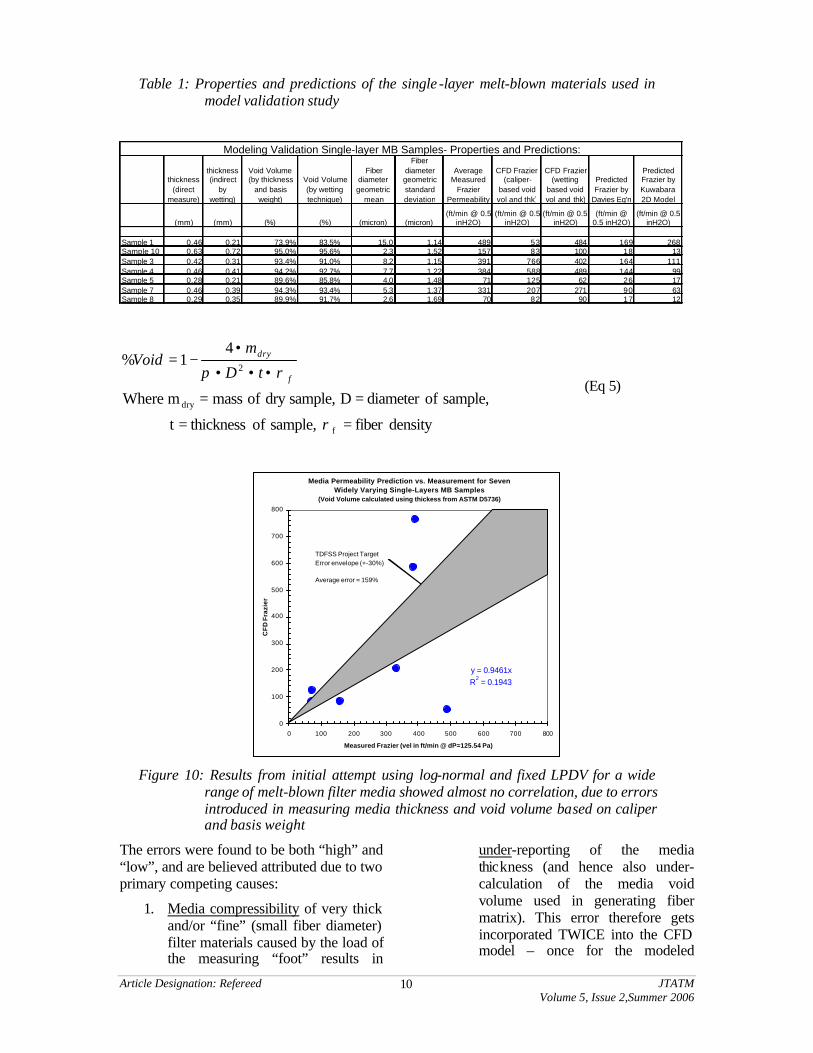
To more widely validate the new approach of using log-normal fibers in partial-random 2D generated structures, seven widely varying single-layer melt-blown materials were collected and characterized via SEM fiber sizing, thickness, void volume, and Frazier permeability (Table 1). Initially, when using a standard method to measure
media thickness (ASTM D5736) and calculate the implied void volume using basis weight and fiber density per Equation 5, a very poor correlation (r2 = 0.19) between prediction and measured permeability was found, as shown in Figure 10.
Article Designation: Refereed JTATM Volume 5, Issue 2,Summer 2006
10
Table 1: Properties and predictions of the single -layer melt-blown materials used in model validation study
thickness (direct
measure)
thickness (indirect
by wetting)
Void Volume (by thickness
and basis weight)
Void Volume (by wetting technique)
Fiber diameter geometric
mean
Fiber diameter geometric standard deviation
Average Measured
Frazier Permeability
CFD Frazier (caliper-
based void vol and thk)
CFD Frazier (wetting
based void vol and thk)
Predicted Frazier by
Davies Eq'n
Predicted Frazier by Kuwabara 2D Model
(mm) (mm) (%) (%) (micron) (micron)(ft/min @ 0.5
inH2O)(ft/min @ 0.5
inH2O)(ft/min @ 0.5
inH2O)(ft/min @
0.5 inH2O)(ft/min @ 0.5
inH2O)
Sample 1 0.46 0.21 73.9% 83.5% 15.0 1.14 489 53 484 169 268Sample 10 0.63 0.72 95.0% 95.6% 2.3 1.52 157 83 100 18 13Sample 3 0.42 0.31 93.4% 91.0% 8.2 1.15 391 766 402 164 111Sample 4 0.46 0.41 94.2% 92.7% 7.7 1.22 384 588 489 144 99Sample 5 0.28 0.21 89.6% 85.8% 4.0 1.48 71 125 62 26 17Sample 7 0.46 0.39 94.3% 93.4% 5.3 1.37 331 207 271 90 63Sample 8 0.29 0.35 89.9% 91.7% 2.6 1.69 70 82 90 17 12
Modeling Validation Single-layer MB Samples- Properties and Predictions:
densityfiber sample, of thickness t
sample, ofdiameter D sample,dry of massm Where
41%
f
dry
2
==
==
•••
•−=
ρ
ρπ f
dry
tD
mVoid
(Eq 5)
Media Permeability Prediction vs. Measurement for Seven
Widely Varying Single-Layers MB Samples(Void Volume calculated using thickess from ASTM D5736)
y = 0.9461xR
2 = 0.1943
0
100
200
300
400
500
600
700
800
0 100 200 300 400 500 600 700 800
Measured Frazier (vel in ft/min @ dP=125.54 Pa)
CF
D F
razi
er
TDFSS Project Target Error envelope (+-30%)
Average error = 159%
Figure 10: Results from initial attempt using log-normal and fixed LPDV for a wide
range of melt-blown filter media showed almost no correlation, due to errors introduced in measuring media thickness and void volume based on caliper and basis weight
The errors were found to be both “high” and “low”, and are believed attributed due to two primary competing causes:
1. Media compressibility of very thick and/or “fine” (small fiber diameter) filter materials caused by the load of the measuring “foot” results in
under-reporting of the media thickness (and hence also under-calculation of the media void volume used in generating fiber matrix). This error therefore gets incorporated TWICE into the CFD model – once for the modeled
Article Designation: Refereed JTATM Volume 5, Issue 2,Summer 2006
11
thickness of media layer and once for the void volume parameter.
2. Surface “texture” imprinted in the media surface by the woven-screen collection drum surface for some stiff, large-fiber materials causes over-reporting of the “true” thickness (from a micro-scale modeling perspective), since the measurement foot rests on the peaks of imprinted projections and includes large void gaps in the measurement. This error also results in over-calculated void volume, and again, a double inclusion of error into subsequent model.
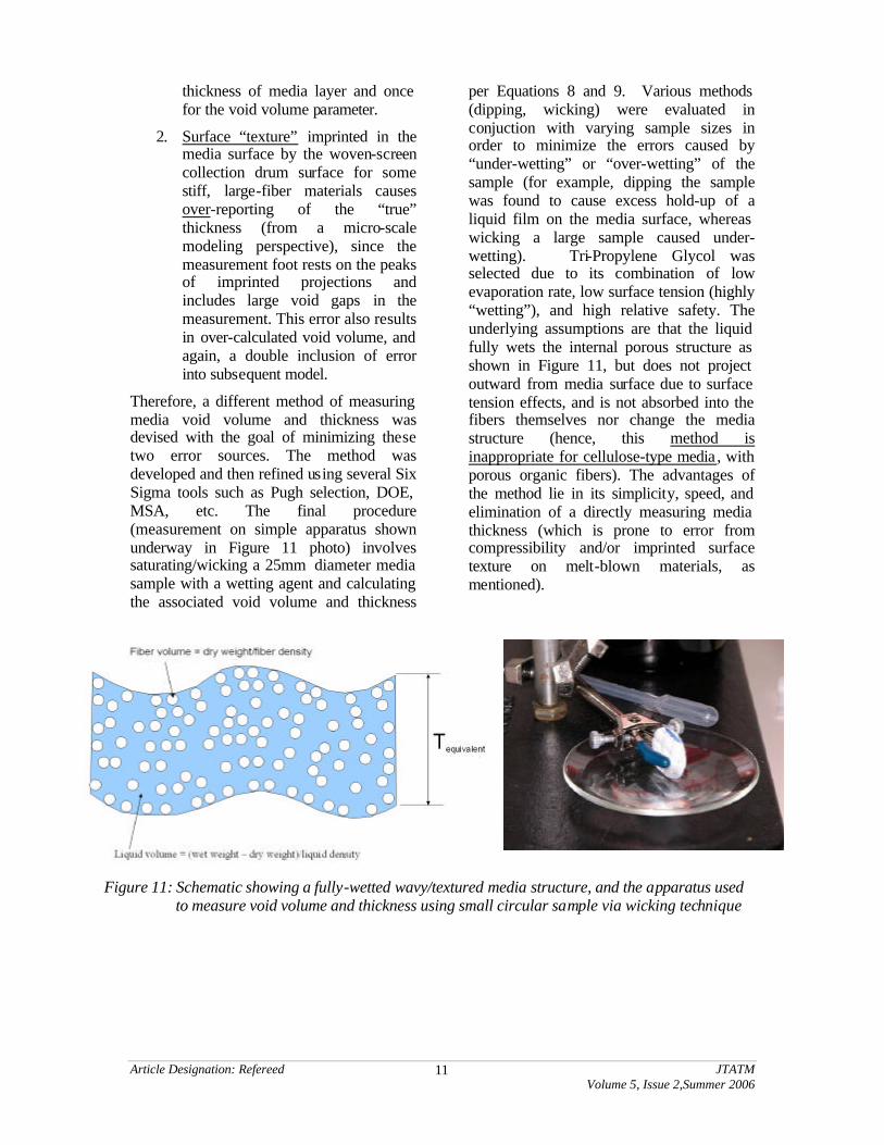
Therefore, a different method of measuring media void volume and thickness was devised with the goal of minimizing these two error sources. The method was developed and then refined using several Six Sigma tools such as Pugh selection, DOE, MSA, etc. The final procedure (measurement on simple apparatus shown underway in Figure 11 photo) involves saturating/wicking a 25mm diameter media sample with a wetting agent and calculating the associated void volume and thickness
per Equations 8 and 9. Various methods (dipping, wicking) were evaluated in conjuction with varying sample sizes in order to minimize the errors caused by “under-wetting” or “over-wetting” of the sample (for example, dipping the sample was found to cause excess hold-up of a liquid film on the media surface, whereas wicking a large sample caused under-wetting). Tri-Propylene Glycol was selected due to its combination of low evaporation rate, low surface tension (highly “wetting”), and high relative safety. The underlying assumptions are that the liquid fully wets the internal porous structure as shown in Figure 11, but does not project outward from media surface due to surface tension effects, and is not absorbed into the fibers themselves nor change the media structure (hence, this method is inappropriate for cellulose-type media , with porous organic fibers). The advantages of the method lie in its simplicity, speed, and elimination of a directly measuring media thickness (which is prone to error from compressibility and/or imprinted surface texture on melt-blown materials, as mentioned).
Figure 11: Schematic showing a fully-wetted wavy/textured media structure, and the apparatus used to measure void volume and thickness using small circular sample via wicking technique
Article Designation: Refereed JTATM Volume 5, Issue 2,Summer 2006
12
100*
+=
fiberliquid
liquid
VV
V(%) Void
(Eq 6)
sample the of Area Amedia, the in volume (liquid) VoidV
media, the in fiber of Volume Vmedia, the of thickness EquivalentT Where
T
sampleliquid
fiberequivalent
equivalent
==
==
+=
Sample
liquidfiber
A
VV )(
(Eq 7)
Or, in directly measured terms:
( )( )
patch, mediadry of mass m
patch, media wettedof mass m density, fluid wetting density, fiber where
dry
wetl
dryldrywet
drywet
=
===
+−
−=
ρρ
ρρ
ρ
f
F
F
mmm
mmVoid%
(Eq 8)
( )sampleA
mmmT
lF
drywetfldryequivalent ρρ
ρρ −+= (Eq 9)
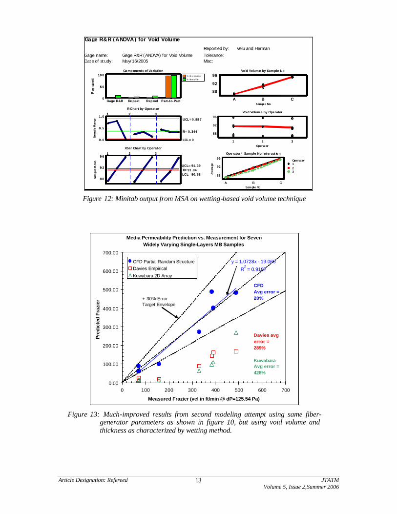
A “measurement system analysis” (MSA), one of the very important TDFSS tools, was conducted on this new method using three operators, three samples, and three replications. The MSA yielded 13 statistically distinct “categories” for media with void volume ranging between 88% - 96% (i.e. adequate of resolving to ~0.5% increments within that range) and showed minimal operator or operator-sample interaction, as shown in Minitab output of Figure 12.
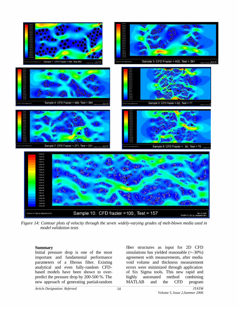
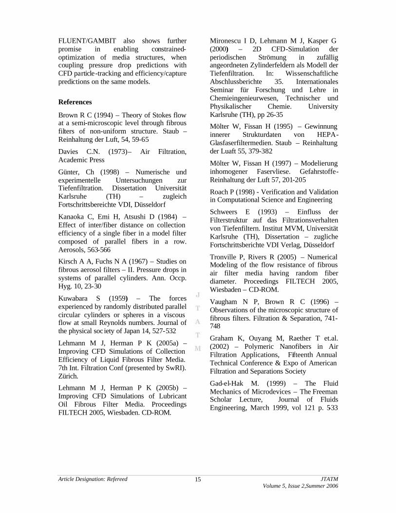
When the CFD model fiber structures were regenerated and re-run based on the new wetting-method thickness and void volume definitions, the correlation was dramatically improved (r2 = 0.92), as shown in Figure 13. Composite Figure 14, showing contour plots
of velocity through the seven different media structures illustrates the dramatic variation in fiber size, void volume, and thickness for the structures. The CFD predicted permeabilities (Figure 13) closely cluster near the x=y dashed line and largely fall within the target envelope of a 30 % uncertainty (20% average error) which is a great improvement over prior attempts (such as shown in Figure 10) which used the void volume and thickness as measured by caliper/basis weight inference. Also, note the dramatic improvement over both the Davies and Kuwabara models which greatly over-predict flow restriction (shown for reference on the same graph) for these same melt-blown media.
Article Designation: Refereed JTATM Volume 5, Issue 2,Summer 2006
13
Per
cent
Part-to-PartReprodRe peatGage R&R
100
50
0
% Co nt rib ut ion
% Stud y Var
Sam
ple
Ran
ge
1.0
0.5
0.0
_R=0.344
UCL =0.887
LCL =0
1 2 3
Sam
ple
Mea
n
96
92
88
__X=91.04
UCL=91.39
LCL=90.68
1 2 3
Sample NoCBA
96
92
88
Operator321
96
92
88
Sample No
Av
era
ge
CBA
96
92
88
Operator123
Gage name: Gage R&R (ANOVA) for Void VolumeDate of study: May/16/2005
Reported by: Velu and Herman
Tolerance:Misc:
Components of Variation
R Chart by Operator
Xbar Chart by Operator
Void Volume by Sample No
Void Volume by Operator
Ope rator * Sample No Interaction
Gage R&R (ANOVA) for Void Volume
Figure 12: Minitab output from MSA on wetting-based void volume technique
Media Permeability Prediction vs. Measurement for Seven Widely Varying Single-Layers MB Samples
y = 1.0728x - 19.066
R2 = 0.9187
0.00
100.00
200.00
300.00
400.00
500.00
600.00
700.00
0 100 200 300 400 500 600 700
Measured Frazier (vel in ft/min @ dP=125.54 Pa)
Pre
dict
ed F
razi
er
CFD Partial Random Structure Davies Empirical
Kuwabara 2D Array
CFD Avg error = 20%
Davies avg error = 289%
Kuwabara Avg error = 428%
+-30% Error Target Envelope
Figure 13: Much-improved results from second modeling attempt using same fiber-
generator parameters as shown in figure 10, but using void volume and thickness as characterized by wetting method.
Article Designation: Refereed JTATM Volume 5, Issue 2,Summer 2006
14
Figure 14: Contour plots of velocity through the seven widely-varying grades of melt-blown media used in
model validation tests
Summary Initial pressure drop is one of the most important and fundamental performance parameters of a fibrous filter. Existing analytical and even fully-random CFD-based models have been shown to over-predict the pressure drop by 200-500 %. The new approach of generating partial-random
fiber structures as input for 2D CFD simulations has yielded reasonable (+-30%) agreement with measurements, after media void volume and thickness measurement errors were minimized through application of Six Sigma tools. This new rapid and highly automated method combining MATLAB and the CFD program
Article Designation: Refereed JTATM Volume 5, Issue 2,Summer 2006
15
FLUENT/GAMBIT also shows further promise in enabling constrained-optimization of media structures, when coupling pressure drop predictions with CFD particle-tracking and efficiency/capture predictions on the same models.
References
Brown R C (1994) – Theory of Stokes flow at a semi-microscopic level through fibrous filters of non-uniform structure. Staub – Reinhaltung der Luft, 54, 59-65
Davies C.N. (1973)– Air Filtration, Academic Press
Günter, Ch (1998) – Numerische und experimentelle Untersuchungen zur Tiefenfiltration. Dissertation Universität Karlsruhe (TH) – zugleich Fortschrittsbereichte VDI, Düsseldorf
Kanaoka C, Emi H, Atsushi D (1984) – Effect of inter/fiber distance on collection efficiency of a single fiber in a model filter composed of parallel fibers in a row. Aerosols, 563-566
Kirsch A A, Fuchs N A (1967) – Studies on fibrous aerosol filters – II. Pressure drops in systems of parallel cylinders. Ann. Occp. Hyg. 10, 23-30
Kuwabara S (1959) – The forces experienced by randomly distributed parallel circular cylinders or spheres in a viscous flow at small Reynolds numbers. Journal of the physical soc iety of Japan 14, 527-532
Lehmann M J, Herman P K (2005a) – Improving CFD Simulations of Collection Efficiency of Liquid Fibrous Filter Media. 7th Int. Filtration Conf (presented by SwRI). Zürich.
Lehmann M J, Herman P K (2005b) – Improving CFD Simulations of Lubricant Oil Fibrous Filter Media. Proceedings FILTECH 2005, Wiesbaden. CD-ROM.
Mironescu I D, Lehmann M J, Kasper G (2000) – 2D CFD-Simulation der periodischen Strömung in zufällig angeordneten Zylinderfeldern als Modell der Tiefenfiltration. In: Wissenschaftliche Abschlussberichte 35. Internationales Seminar für Forschung und Lehre in Chemieingenieurwesen, Technischer und Physikalischer Chemie. University Karlsruhe (TH), pp 26-35
Mölter W, Fissan H (1995) – Gewinnung innerer Strukturdaten von HEPA-Glasfaserfiltermedien. Staub – Reinhaltung der Luaft 55, 379-382
Mölter W, Fissan H (1997) – Modelierung inhomogener Faservliese. Gefahrstoffe- Reinhaltung der Luft 57, 201-205
Roach P (1998) - Verification and Validation in Computational Science and Engineering
Schweers E (1993) – Einfluss der Filterstruktur auf das Filtrationsverhalten von Tiefenfiltern. Institut MVM, Universität Karlsruhe (TH), Dissertation – zugliche Fortschrittsberichte VDI Verlag, Düsseldorf
Tronville P, Rivers R (2005) – Numerical Modeling of the flow resistance of fibrous air filter media having random fiber diameter. Proceedings FILTECH 2005, Wiesbaden – CD-ROM.
Vaugham N P, Brown R C (1996) – Observations of the microscopic structure of fibrous filters. Filtration & Separation, 741-748
Graham K, Ouyang M, Raether T et.al. (2002) – Polymeric Nanofibers in Air Filtration Applications, Fifteenth Annual Technical Conference & Expo of American Filtration and Separations Society
Gad-el-Hak M. (1999) – The Fluid Mechanics of Microdevices – The Freeman Scholar Lecture, Journal of Fluids Engineering, March 1999, vol 121 p. 5-33